WO2014193160A1 - Apparatus for transmitting broadcast signal, apparatus for receiving broadcast signal, method for transmitting broadcast signal, and method for receiving broadcast signal - Google Patents
Apparatus for transmitting broadcast signal, apparatus for receiving broadcast signal, method for transmitting broadcast signal, and method for receiving broadcast signal Download PDFInfo
- Publication number
- WO2014193160A1 WO2014193160A1 PCT/KR2014/004762 KR2014004762W WO2014193160A1 WO 2014193160 A1 WO2014193160 A1 WO 2014193160A1 KR 2014004762 W KR2014004762 W KR 2014004762W WO 2014193160 A1 WO2014193160 A1 WO 2014193160A1
- Authority
- WO
- WIPO (PCT)
- Prior art keywords
- block
- broadcast
- data
- signal
- broadcast service
- Prior art date
Links
Images


Classifications
-
- H—ELECTRICITY
- H04—ELECTRIC COMMUNICATION TECHNIQUE
- H04H—BROADCAST COMMUNICATION
- H04H20/00—Arrangements for broadcast or for distribution combined with broadcast
- H04H20/65—Arrangements characterised by transmission systems for broadcast
- H04H20/71—Wireless systems
- H04H20/72—Wireless systems of terrestrial networks
-
- H—ELECTRICITY
- H04—ELECTRIC COMMUNICATION TECHNIQUE
- H04L—TRANSMISSION OF DIGITAL INFORMATION, e.g. TELEGRAPHIC COMMUNICATION
- H04L5/00—Arrangements affording multiple use of the transmission path
- H04L5/0001—Arrangements for dividing the transmission path
- H04L5/0003—Two-dimensional division
- H04L5/0005—Time-frequency
- H04L5/0007—Time-frequency the frequencies being orthogonal, e.g. OFDM(A), DMT
-
- H—ELECTRICITY
- H04—ELECTRIC COMMUNICATION TECHNIQUE
- H04B—TRANSMISSION
- H04B7/00—Radio transmission systems, i.e. using radiation field
- H04B7/02—Diversity systems; Multi-antenna system, i.e. transmission or reception using multiple antennas
- H04B7/04—Diversity systems; Multi-antenna system, i.e. transmission or reception using multiple antennas using two or more spaced independent antennas
- H04B7/0413—MIMO systems
-
- H—ELECTRICITY
- H04—ELECTRIC COMMUNICATION TECHNIQUE
- H04H—BROADCAST COMMUNICATION
- H04H20/00—Arrangements for broadcast or for distribution combined with broadcast
-
- H—ELECTRICITY
- H04—ELECTRIC COMMUNICATION TECHNIQUE
- H04L—TRANSMISSION OF DIGITAL INFORMATION, e.g. TELEGRAPHIC COMMUNICATION
- H04L1/00—Arrangements for detecting or preventing errors in the information received
-
- H—ELECTRICITY
- H04—ELECTRIC COMMUNICATION TECHNIQUE
- H04L—TRANSMISSION OF DIGITAL INFORMATION, e.g. TELEGRAPHIC COMMUNICATION
- H04L1/00—Arrangements for detecting or preventing errors in the information received
- H04L1/004—Arrangements for detecting or preventing errors in the information received by using forward error control
- H04L1/0041—Arrangements at the transmitter end
-
- H—ELECTRICITY
- H04—ELECTRIC COMMUNICATION TECHNIQUE
- H04L—TRANSMISSION OF DIGITAL INFORMATION, e.g. TELEGRAPHIC COMMUNICATION
- H04L1/00—Arrangements for detecting or preventing errors in the information received
- H04L1/004—Arrangements for detecting or preventing errors in the information received by using forward error control
- H04L1/0045—Arrangements at the receiver end
-
- H—ELECTRICITY
- H04—ELECTRIC COMMUNICATION TECHNIQUE
- H04L—TRANSMISSION OF DIGITAL INFORMATION, e.g. TELEGRAPHIC COMMUNICATION
- H04L1/00—Arrangements for detecting or preventing errors in the information received
- H04L1/004—Arrangements for detecting or preventing errors in the information received by using forward error control
- H04L1/0056—Systems characterized by the type of code used
- H04L1/0057—Block codes
-
- H—ELECTRICITY
- H04—ELECTRIC COMMUNICATION TECHNIQUE
- H04L—TRANSMISSION OF DIGITAL INFORMATION, e.g. TELEGRAPHIC COMMUNICATION
- H04L1/00—Arrangements for detecting or preventing errors in the information received
- H04L1/004—Arrangements for detecting or preventing errors in the information received by using forward error control
- H04L1/0056—Systems characterized by the type of code used
- H04L1/0064—Concatenated codes
- H04L1/0065—Serial concatenated codes
-
- H—ELECTRICITY
- H04—ELECTRIC COMMUNICATION TECHNIQUE
- H04L—TRANSMISSION OF DIGITAL INFORMATION, e.g. TELEGRAPHIC COMMUNICATION
- H04L1/00—Arrangements for detecting or preventing errors in the information received
- H04L1/004—Arrangements for detecting or preventing errors in the information received by using forward error control
- H04L1/0056—Systems characterized by the type of code used
- H04L1/0071—Use of interleaving
-
- H—ELECTRICITY
- H04—ELECTRIC COMMUNICATION TECHNIQUE
- H04L—TRANSMISSION OF DIGITAL INFORMATION, e.g. TELEGRAPHIC COMMUNICATION
- H04L1/00—Arrangements for detecting or preventing errors in the information received
- H04L1/02—Arrangements for detecting or preventing errors in the information received by diversity reception
- H04L1/06—Arrangements for detecting or preventing errors in the information received by diversity reception using space diversity
- H04L1/0618—Space-time coding
-
- H—ELECTRICITY
- H04—ELECTRIC COMMUNICATION TECHNIQUE
- H04L—TRANSMISSION OF DIGITAL INFORMATION, e.g. TELEGRAPHIC COMMUNICATION
- H04L5/00—Arrangements affording multiple use of the transmission path
- H04L5/003—Arrangements for allocating sub-channels of the transmission path
- H04L5/0048—Allocation of pilot signals, i.e. of signals known to the receiver
-
- H—ELECTRICITY
- H04—ELECTRIC COMMUNICATION TECHNIQUE
- H04L—TRANSMISSION OF DIGITAL INFORMATION, e.g. TELEGRAPHIC COMMUNICATION
- H04L65/00—Network arrangements, protocols or services for supporting real-time applications in data packet communication
- H04L65/60—Network streaming of media packets
- H04L65/70—Media network packetisation
-
- H—ELECTRICITY
- H04—ELECTRIC COMMUNICATION TECHNIQUE
- H04H—BROADCAST COMMUNICATION
- H04H60/00—Arrangements for broadcast applications with a direct linking to broadcast information or broadcast space-time; Broadcast-related systems
- H04H60/68—Systems specially adapted for using specific information, e.g. geographical or meteorological information
- H04H60/73—Systems specially adapted for using specific information, e.g. geographical or meteorological information using meta-information
Definitions
- the present invention relates to a broadcast signal transmission apparatus for transmitting a broadcast signal, a broadcast signal reception apparatus for receiving a broadcast signal, and a method for transmitting and receiving a broadcast signal.
- the digital broadcast signal may include a larger amount of video / audio data than the analog broadcast signal, and may include various additional data in addition to the video / audio data.
- the digital broadcasting system for digital broadcasting may provide HD (High Definition) level images, multi-channel sound, and various additional services.
- HD High Definition
- data transmission efficiency for high-capacity data transmission, robustness of the transmission / reception network, and flexibility of the network considering mobile reception equipment still need to be improved.
- an object of the present invention is to provide a broadcast signal transmitting apparatus capable of transmitting and receiving broadcast signals for future broadcast services, a broadcast signal receiving apparatus, and a method of transmitting and receiving broadcast signals for next-generation broadcast services. To provide.
- An object of the present invention is to provide a broadcast signal transmission apparatus and a broadcast signal transmission method capable of transmitting data through a same RF signal bandwidth by multiplexing data of a broadcast transmission / reception system providing two or more different broadcast services in a time domain, and There is provided a corresponding broadcast signal receiving apparatus and broadcast signal receiving method.
- Another object of the present invention is to classify data corresponding to a service by component, and to transmit, receive, and process data corresponding to each component in a separate data pipe (hereinafter referred to as DP).
- DP separate data pipe
- Another object of the present invention is to provide a broadcast signal transmission apparatus for signaling signaling information required for serving a broadcast signal, a broadcast signal reception apparatus, and a method for transmitting and receiving broadcast signals.
- a method of transmitting broadcast signals comprising encoding DP data corresponding to a DP (Data pipe) for transmitting at least one broadcast service or broadcast service component, and at least one
- the above broadcast service corresponds to any one of a broadcast service for a fixed receiver or a broadcast service for a mobile receiver, and mapping encoded DP data to constellation, time interleaving the mapped DP data, and time interleaved DP.
- Generating at least one signal frame comprising data, inserting at least one or more pilots into the generated at least one signal frame according to at least one pilot pattern, wherein the at least one pilot pattern is broadcast for a fixed receiver; Service or mobile OFDM modulation is performed for different broadcast services for the broadcast service, and the at least one signal frame generated by using orthogonal frequency division multiplexing (OFDM) parameters, wherein the OFDM parameters are determined according to the size of the fast fourier transform (FFT) And transmitting at least one broadcast signal including the determined and modulated at least one signal frame.
- OFDM orthogonal frequency division multiplexing
- the present invention processes data according to characteristics of a service in order to provide various broadcasting services, thereby controlling QoS for each service or service component.
- the present invention can secure transmission flexibility by transmitting various broadcast services through the same RF signal bandwidth.
- the present invention can increase data transmission efficiency and increase robustness of transmitting and receiving broadcast signals by using a MIMO system.
- the present invention it is possible to provide a method and apparatus for transmitting and receiving a broadcast signal capable of receiving a digital broadcast signal without error even in a mobile reception device or an indoor environment.
- FIG. 1 is a diagram illustrating a structure of a transmission apparatus for a next generation broadcast service according to an embodiment of the present invention.
- FIG. 2 illustrates an input formatting module according to an embodiment of the present invention.
- 3 illustrates an input formatting module according to another embodiment of the present invention.
- FIG 4 illustrates an input formatting module according to another embodiment of the present invention.
- FIG. 5 illustrates a coding and modulation module according to an embodiment of the present invention.
- FIG. 6 is a diagram illustrating a frame structure module according to an embodiment of the present invention.
- FIG. 7 illustrates a waveform generation module according to an embodiment of the present invention.
- FIG. 8 is a diagram illustrating a structure of a reception device for a next generation broadcast service according to an embodiment of the present invention.
- FIG 9 illustrates a synchronization and demodulation module according to an embodiment of the present invention.
- FIG. 10 illustrates a frame parsing module according to an embodiment of the present invention.
- FIG. 11 illustrates a demapping & decoding module according to an embodiment of the present invention.
- FIG 12 illustrates an output processor according to an embodiment of the present invention.
- FIG 13 illustrates an output processor according to another embodiment of the present invention.
- FIG. 14 illustrates a coding and modulation module according to another embodiment of the present invention.
- FIG. 15 illustrates a demapping & decoding module according to another embodiment of the present invention.
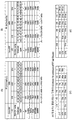
- FIG. 16 illustrates a table showing information related to a reception mode according to an embodiment of the present invention.
- FIG. 17 illustrates a bandwidth of a broadcast signal according to an embodiment of the present invention.
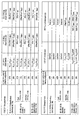
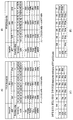
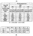
- 19 is a table showing transmission parameters for optimizing eBW according to an embodiment of the present invention.
- 20 is a table showing transmission parameters for optimizing eBW according to another embodiment of the present invention.
- 21 is a table showing transmission parameters for optimizing eBW according to another embodiment of the present invention.
- 22 is a table showing transmission parameters according to another embodiment of the present invention.
- FIG. 23 is a graph illustrating Power Spectral Density (PSD) of a transmission signal according to an embodiment of the present invention.
- PSD Power Spectral Density
- 24 is a table illustrating information related to a reception mode according to another embodiment of the present invention.
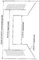
- 25 illustrates a relationship between a maximum channel estimation range and a guard interval according to an embodiment of the present invention.
- FIG. 26 is a diagram illustrating a table defining pilot parameters according to an embodiment of the present invention.
- 27 is a diagram illustrating a table defining pilot parameters according to another embodiment of the present invention.
- FIG. 30 illustrates a MIXO-2 pilot pattern according to an embodiment of the present invention.
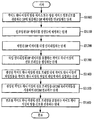
- 31 is a flowchart of a broadcast signal transmission method according to an embodiment of the present invention.
- 32 is a flowchart of a broadcast signal receiving method according to an embodiment of the present invention.
- the present invention is to provide an apparatus and method for transmitting and receiving broadcast signals for the next generation broadcast service.
- the next generation broadcast service according to an embodiment of the present invention is a concept including a terrestrial broadcast service, a mobile broadcast service, and a UHDTV service.
- the broadcast signal for the next generation broadcast service may be processed using a non-MIMO (Multi Input Multi Output) method or a MIMO method according to the characteristics of the broadcast service.
- the non-MIMO scheme according to an embodiment of the present invention may include a MISO (Multi Input Single Output), a SISO (Single Input Single Output) scheme, and the like.
- multiple antennas of MISO or MIMO may be described with two antennas as an example for convenience of description, but the description of the present invention may be applied to a system using two or more antennas.
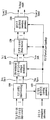
- FIG. 1 is a diagram illustrating a structure of a transmission apparatus for a next generation broadcast service according to an embodiment of the present invention.
- a transmission apparatus for a next generation broadcast service includes an input formatting module 1000, a coding & modulation module 1100, and a frame structure module 1200. It may include a waveform generation module 1300 and a signaling generation module 1400. Hereinafter, the operation of each module will be described.
- the apparatus for transmitting a next generation broadcast service may receive an MPEG-TS stream, an IP stream (v4 / v6), and a GS (generic stream) as input signals. .
- the input formatting module 1000 divides the input streams according to a criterion for performing coding and modulation or a service and service component criterion.
- a criterion for performing coding and modulation or a service and service component criterion.
- DPs or DP data may be referred to as DP data.
- the input formatting module 1000 divides each generated DP into block units necessary to perform coding and modulation, and performs a series of processes required to increase transmission efficiency or to schedule the DP. can do. Details will be described later.
- the coding and modulation module 1100 performs forward error correction (FEC) encoding on each DP received from the input formatting module 1000 to receive an error that may occur in a transport channel at a receiving end. Allow modification.
- the coding and modulation module 1100 according to an embodiment of the present invention may convert the bit data of the FEC output into symbol data and perform interleaving to correct a burst error due to a channel.
- the coding and modulation module 1100 according to an embodiment of the present invention provides a data path for outputting processed data to each antenna. (Or antenna path) can be output separately.
- the frame structure module 1200 may map data output from the coding and modulation module 1100 to a signal frame (or frame).
- the frame structure module 1200 may perform mapping by using the scheduling information output from the input formatting module 1000, and in the signal frame in order to obtain additional diversity gain. Interleaving can be performed on the data.
- the waveform generation module 1300 may convert the signal frames output from the frame structure module 1200 into a signal that can be finally transmitted.
- the waveform generation module 1300 according to an embodiment of the present invention inserts a preamble signal (or preamble) in order to obtain a signal frame of a transmission system in a receiver, estimates a transmission channel, and adjusts distortion.
- a reference signal can be inserted to compensate.
- the waveform generation module 1300 according to an embodiment of the present invention has a guard interval in order to cancel an influence caused by a channel delay spread due to multipath reception, and a specific sequence in a corresponding section. You can insert
- the waveform generation module 1300 according to an embodiment of the present invention may additionally perform a process necessary for efficient transmission in consideration of signal characteristics such as peak-to-average power ratio (PAPR) of an output signal. .
- PAPR peak-to-average power ratio
- the signaling generation module 1400 uses the input side information and information generated by the input formatting module 1000, the coding and modulation module 1100, and the frame structure module 1200.
- Signaling information (physical layer signaling information, hereinafter referred to as PLS information) is generated. Therefore, the reception apparatus according to an embodiment of the present invention can decode the received signal by decoding the signaling information.
- the transmitter for the next generation broadcast service may provide a terrestrial broadcast service, a mobile broadcast service, and a UHDTV service. Therefore, the apparatus for transmitting a next-generation broadcast service according to an embodiment of the present invention may multiplex signals for different services in a time domain and transmit the same.
- FIG. 2 to 4 illustrate an embodiment of the input formatting module 1000 according to an embodiment of the present invention described with reference to FIG. 1. Each figure is demonstrated below.
- FIG. 2 illustrates an input formatting module according to an embodiment of the present invention. 2 illustrates an input formatting module when the input signal is a single input stream.
- an input formatting module may include a mode adaptation module 2000 and a stream adaptation module 2100.
- the mode adaptation module 2000 includes an input interface block 2010, a CRC-8 encoder block 2020, and a BB header insertion block (20). 2030). Each block is briefly described below.
- the input interface block 2010 may output the input single input stream by dividing the input single input stream into units of a baseband (BB) frame length for performing FEC (BCH / LDPC).
- BB baseband
- the CRC-8 encoder block 2020 may add redundancy data by performing CRC encoding on data of each BB frame.
- the BB header insertion block 2030 may include a mode adaptation type (TS / GS / IP), a user packet length, a data field length, and a user packet sink byte ( User Packet Sync Byte, Start Address of User Packet Sync Byte in Data Field, High Efficiency Mode Indicator, Input Stream Synchronization Field, etc. Header can be inserted into the BB frame.
- a mode adaptation type TS / GS / IP
- a user packet length a data field length
- a user packet sink byte User Packet Sync Byte, Start Address of User Packet Sync Byte in Data Field, High Efficiency Mode Indicator, Input Stream Synchronization Field, etc. Header can be inserted into the BB frame.
- the stream adaptation module 2100 may include a padding insertion block 2110 and a BB scrambler block 2120. Each block is briefly described below.
- the padding insertion block 2110 may insert a padding bit and output the padding bit to have the required input data length.
- the BB scrambler block 2120 may randomize an input bit stream by performing an XOR using a pseudo random binary sequence (PRBS).
- PRBS pseudo random binary sequence
- the aforementioned blocks may be omitted or replaced by other blocks having similar or identical functions according to the designer's intention.
- the input formatting module may finally output the DP to the coding and modulation module.
- 3 illustrates an input formatting module according to another embodiment of the present invention. 3 illustrates a mode adaptation module of an input formatting module when the input signal is multiple input streams.
- the mode adaptation module of the input formatting module for processing multiple input streams may process each input stream independently.
- the mode adaptation module 3000 for processing multiple input streams respectively includes an input interface block, an input stream synchronizer block, and a compensating delay.
- a block, a null packet deletion block, a CRC-8 encoder block, and a BB header insertion block may be included. Each block is briefly described below.
- the input stream synchronizer block 3100 may transmit input stream clock reference (ISCR) information and insert timing information necessary for reconstructing a TS or GS stream at a receiving end.
- ISCR input stream clock reference
- the compensating delay block 3200 outputs the delayed input data so that the receiving device can synchronize in case of a delay between DPs according to data processing of the transmitting device together with timing information generated by the input stream synchronizer block. can do.
- the null packet deletion block 3300 may remove an input null packet to be transmitted unnecessarily and insert and transmit the number of removed null packets according to the removed position.
- the aforementioned blocks may be omitted or replaced by other blocks having similar or identical functions according to the designer's intention.
- FIG 4 illustrates an input formatting module according to another embodiment of the present invention.
- FIG. 4 illustrates a stream adaptation module of the input formatting module when the input signal is a multiple input stream.
- the stream adaptation module of the input formatting module in the case of multiple input streams may include a scheduler 4000, a 1-frame delay block 4100, in-band signaling or padding. It may include an in-band signaling or padding insertion block 4200, a physical layer signaling (PLS) block 4300, and a BB scrambler block 4400. The operation of each block will be described below.
- the scheduler 4000 may perform scheduling for a MIMO system using multiple antennas including dual polarity.
- the scheduler 4000 is a signal for each antenna path such as a bit to cell demux block, a cell interleaver block, and a time interleaver block in the coding and modulation module described with reference to FIG. 1. Parameters to be used in the processing blocks can be generated.
- the 1-frame delay block 4100 may delay the input data by one signal frame so that scheduling information for the next frame can be transmitted in the current frame for in-band signaling to be inserted into the DP.
- the in-band signaling or padding insertion block 4200 can insert non-delayed PLS-dynamic signaling information into data delayed by one signal frame.
- the in-band signaling or padding insertion block 4200 may insert padding bits when there is space for padding or insert in-band signaling information into the padding space.
- the scheduler 4000 may output PLS-dynamic signaling information for the current frame separately from in-band signaling. Accordingly, the cell mapper described later may map input cells according to scheduling information output from the scheduler 4000.
- the PLS generation block 4300 may generate PLS data (or PLS) to be transmitted to a preamble symbol or a spread symbol of a signal frame except for in-band signaling.
- PLS data according to an embodiment of the present invention may be referred to as signaling information.
- PLS data according to an embodiment of the present invention may be divided into PLS-free information and PLS-post information.
- the PLS-free information may include parameters necessary for the broadcast signal receiving apparatus to decode the PLS-post information and static PLS signaling information.
- the PLS-post information may include parameters necessary for the broadcast signal receiving apparatus to decode the DP. It may include.
- the parameters required for decoding the above-described DP may be separated into static PLS signaling information and dynamic PLS signaling information.
- the static PLS signaling information is a parameter that can be commonly applied to all frames included in the super frame and can be changed in units of super frames.
- the dynamic PLS signaling information is a parameter that can be applied differently for each frame included in the super frame and can be changed in units of frames. Therefore, the receiving device can decode the PLS-free information to obtain PLS-post information, and decode the desired DP by decoding the PLS-post information.
- the BB scrambler block 4400 may generate a PRBS so that the PAPR value of the output signal of the waveform generation block may be lowered and XOR the input bit string to output the PRBS. As shown in FIG. 4, scrambling of the BB scrambler block 4400 may be applied to both DP and PLS.
- the aforementioned blocks may be omitted or replaced by other blocks having similar or identical functions according to the designer's intention.
- the stream adaptation module may finally output each data pipe to a coding and modulation module.
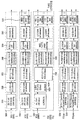
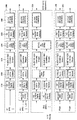
- FIG. 5 illustrates a coding and modulation module according to an embodiment of the present invention.
- the coding and modulation module of FIG. 5 corresponds to an embodiment of the coding and modulation module 1100 described with reference to FIG. 1.
- the transmitter for the next generation broadcast service may provide a terrestrial broadcast service, a mobile broadcast service, and a UHDTV service.
- the coding & modulation module can independently process and process SISO, MISO, and MIMO schemes for each of the input DPs.
- the transmission apparatus for the next generation broadcast service may adjust QoS for each service or service component transmitted through each DP.
- the coding and modulation module includes a first block 5000 for the SISO method, a second block 5100 for the MISO method, a third block 5200 for the MIMO method, and a PLS-free method. And a fourth block 5300 for processing the post information.
- the coding and modulation module illustrated in FIG. 5 is only an example, and according to a designer's intention, the coding and modulation module may include only the first block 5000 and the fourth block 5300, and the second block 5100. ) And only the fourth block 5300, or may include only the third block 5200 and the fourth block 5300. That is, according to the designer's intention, the coding and modulation module may include blocks for processing each DP identically or differently.
- the first block 5000 is a block for SISO processing the input DP.
- the FEC encoder block 5010, the bit interleaver block 5020, and a bit to cell demux are used.
- the block 5030 may include a constellation mapper block 5040, a cell interleaver block 5050, and a time interleaver block 5060.
- the FEC encoder block 5010 may add redundancy by performing BCH encoding and LDPC encoding on the input DP, and correct an error on a transport channel at the receiving end to output the FEC block.
- the bit interleaver block 5020 may interleave the bit string of the FEC-encoded data by interleaving rules so as to be robust against burst errors that may occur in the transport channel. Therefore, when K fading or deep erasure is applied to a QAM symbol, interleaved bits are mapped to each QAM symbol, thereby preventing errors in consecutive bits among all codeword bits. .
- the bit-to-cell demux block 5030 determines the order of the input bit strings so that each bit in the FEC block can be transmitted with appropriate robustness in consideration of both the order of the input bit strings and the constellation mapping rule. can do.
- bit interleaver 5020 is located between the FEC encoder 5010 and the constellation mapper block 5040, and considering the LDPC decode of the receiver, the output bits of the LDPC encoding performed by the FEC encoder block 5010 are converted to each other in the constellation mapper block. It may serve to connect with a bit position having another reliability and an optimal value. Accordingly, the bit to cell demux block 5030 may be replaced by another block having similar or identical functions.
- the constellation mapper block 5040 may map the input bit word to one constellation.
- the constellation mapper block may additionally perform rotation & Q-delay. That is, the constellation mapper block rotates the input constellations according to the rotation angle and divides the Q component into an arbitrary value after dividing it into I (In-phase) and Q (Quadrature-phase) components. Can be delayed. The paired I and Q components can then be remapped to a new constellation.
- the constellation mapper block 5040 may perform an operation of moving the constellation points on the two-dimensional plane to find the optimal constellation points. Through this process, the capacity of the coding and modulation module 1100 may be optimized. In addition, the constellation mapper block 5040 may perform the above-described operation using IQ-balanced constellation points and a rotation scheme. In addition, the constellation mapper block 5040 may be replaced by another block having similar or identical functions.
- the cell interleaver block 5050 randomly mixes and outputs cells corresponding to one FEC block, and outputs cells corresponding to each FEC block in different orders for each FEC block.
- the time interleaver block 5060 may mix and output cells belonging to several FEC blocks. Accordingly, since the cells of each FEC block are transmitted in a distributed manner as much as a time interleaving depth, diversity gain can be obtained.
- the second block 5100 is a block for MISO processing the input DP.
- the FEC encoder block, the bit interleaver block, the bit-to-cell demux block, and constellation are the same as the first block 5000. Although it may include a migration mapper block, a cell interleaver block, and a time interleaver block, there is a difference in that it further includes a MISO processing block 5110.
- the second block 5100 performs the same role process from the input to the time interleaver, and thus description of the same blocks will be omitted.
- the MISO processing block 5110 may perform encoding on an input series of cells according to an MISO encoding matrix that provides transmit diversity and output MISO processed data through two paths.
- MISO processing according to an embodiment of the present invention may include orthogonal space time block coding (OSTBC) / orthogonal space frequency block coding (OSA).
- OSTBC orthogonal space time block coding
- OSA orthogonal space frequency block coding
- the third block 5200 is a block for MIMO processing the input DP.
- the FEC encoder block, the bit interleaver block, the bit-to-cell demux block, and constellation are the same as the second block 5100. Although it may include a migration mapper block, a cell interleaver block, and a time interleaver block, there is a difference in data processing in that it includes a MIMO processing block 5220.
- the FEC encoder block and the bit interleaver block have different specific functions from those of the first and second blocks 5000 and 5100, but have the same basic role.
- the bit-to-cell demux block 5210 may generate an output bit string equal to the number of inputs of the MIMO processing and output the same through the MIMO path for the MIMO processing.
- the bit-to-cell demux block 5210 may be designed to optimize decoding performance of the receiver in consideration of characteristics of LDPC and MIMO processing.
- the constellation mapper block, the cell interleaver block, and the time interleaver block may also have different specific functions, but the basic role is the same as described in the first and second blocks 5000 and 5100.
- the constellation mapper block, the cell interleaver block, and the time interleaver blocks exist as many as the number of MIMO paths for MIMO processing to process the output bit string output from the bit-to-cell demux block. Can be.
- the constellation mapper block, the cell interleaver block, and the time interleaver block may operate identically or independently for data input through each path.
- the MIMO processing block 5220 may perform MIMO processing on the input two input cells using the MIMO encoding matrix and output the MIMO processed data through two paths.
- MIMO encoding matrix according to an embodiment of the present invention is the SM matrix (spatial multiplexing), golden code (Golden code), full-rate full diversity code (Full-rate full diversity code), linear dispersion code (Linear dispersion code) ) May be included.
- the fourth block 5300 is a block for processing the PLS-pre / post information, and may perform SISO or MISO processing.
- bit interleaver block, the bit to cell demux block, the constellation mapper block, the cell interleaver block, the time interleaver block, and the MISO processing block included in the fourth block 5300 are included in the second block 5100 described above. Blocks and specific functions may be different, but the basic role is the same.
- the shortened / punctured FEC encoder block 5310 included in the fourth block 5300 uses the FEC encoding scheme for the PLS path in case the length of the input data is shorter than the length required to perform FEC encoding. To process the PLS data. Specifically, the FEC encoder block 5310 performs BCH encoding on the input bit stream, then zero padding the length of the input bit stream necessary for normal LDPC encoding, and then pads zeros after the LDPC encoding. By removing, the parity bit can be punctured so that the effective code rate is equal to or lower than the DP.
- the blocks included in the first block 5000 to the fourth block 5300 described above may be omitted or replaced by other blocks having similar or identical functions according to a designer's intention.
- the coding and modulation module may output DP, PLS-pre information, and PLS-post information finally processed for each path to the frame structure module.
- FIG. 6 is a diagram illustrating a frame structure module according to an embodiment of the present invention.
- the frame structure module illustrated in FIG. 6 corresponds to an embodiment of the frame structure module 1200 described with reference to FIG. 1.
- the frame structure block includes at least one cell mapper 6000, at least one delay compensation module 6100, and at least one block interleaver ( 6200).
- the number of cell mapper 6000, delay compensation module 6100, and block interleaver 6200 can be changed according to a designer's intention. Hereinafter, the operation of each module will be described.
- the cell mapper 6000 may include cells corresponding to SISO or MISO or MIMO processed DPs output from the coding and modulation module, cells corresponding to common data that may be commonly applied between DPs, and PLS-pre / post information. Cells corresponding to may be allocated (or arranged) to a signal frame according to scheduling information.
- the common data refers to signaling information that can be commonly applied between all or some of the DPs and can be transmitted through a specific DP.
- a DP that transmits common data may be referred to as a common DP, which can be changed according to a designer's intention.
- the cell mapper 6000 may perform pair-wise cell mapping. That is, the cell mapper 6000 may process two consecutive cells with respect to the input cells in one unit and map them to a signal frame. Therefore, paired cells in the input path corresponding to the output path of each antenna may be allocated to positions adjacent to each other in the signal frame.
- the delay compensation block 6100 may delay the input PLS data cell for the next signal frame by one signal frame to obtain PLS data corresponding to the current signal frame.
- the PLS data of the current signal frame may be transmitted through a preamble region within the current signal frame
- the PLS data for the next signal frame may be transmitted through a preamble region within the current signal frame or through in-band signaling in each DP of the current signal frame. Can be sent. This can be changed according to the designer's intention.
- the block interleaver 6200 may obtain additional diversity gain by interleaving cells in a transport block that is a unit of a signal frame.
- the block interleaver 6200 may perform interleaving by processing two consecutive cells with respect to input cells as one unit. Therefore, the cells output from the block interleaver 6200 may be the same two consecutive cells.
- At least one cell mapper and at least one block interleaver may operate identically or independently for data input through respective paths.
- the aforementioned blocks may be omitted or replaced by other blocks having similar or identical functions according to the designer's intention.
- the frame structure module may output at least one signal frame to the waveform generation module.
- FIG. 7 illustrates a waveform generation module according to an embodiment of the present invention.
- the waveform generation module illustrated in FIG. 7 corresponds to an embodiment of the waveform generation module 1300 described with reference to FIG. 1.
- the waveform generation module may modulate and transmit signal frames as many as the number of antennas for receiving and outputting signal frames output from the frame structure module described with reference to FIG. 6.
- the waveform generation module illustrated in FIG. 7 is an embodiment of the waveform generation module of a transmission apparatus using m Tx antennas, and includes m processing blocks for modulating and outputting frames input by m paths. can do.
- the m processing blocks may all perform the same processing.
- the operation of the first processing block 7000 of the m processing blocks will be described.
- the first processing block 7000 includes a reference signal insertion & PAPR reduction block 7100, an inverse waveform transform block 7200, and a PAPR reduction in time.
- Block 7300 Guard Sequence Insertion Block 7400, Preamble Insertion Block 7500, Waveform Processing Block 7600, Other System Insulation insertion (block) 7770 and a digital analog conveter (DAC) block 7800.
- DAC digital analog conveter
- the reference signal insertion and PAPR reduction block 7100 may insert reference signals at predetermined positions for each signal block and apply a PAPR reduction scheme to lower the PAPR value in the time domain.
- the broadcast transmission / reception system according to an embodiment of the present invention is an OFDM system
- the reference signal insertion and PAPR reduction block 7100 may use a method of preserving without using some of the active subcarriers.
- the reference signal insertion and PAPR reduction block 7100 may not use the PAPR reduction scheme as an additional feature according to the broadcast transmission / reception system.
- the inverse waveform transform block 7200 may span the output signal and output the input signal in such a manner that transmission efficiency and flexibility are improved in consideration of the characteristics of the transmission channel and the system structure.
- the broadcast transmission / reception system according to an embodiment of the present invention is an OFDM system
- the inverse waveform transform block 7200 may use a method of converting a signal in a frequency domain into a time domain using an inverse FFT operation. Can be.
- the broadcast transmission / reception system according to an embodiment of the present invention is a single carrier system, the inverse waveform transform block may not be used in the waveform generation module.
- the PAPR reduction block 7300 may apply a method for lowering PAPR in the time domain with respect to the input signal.
- the PAPR reduction block 7300 may simply use a method of clipping peak amplitude.
- the PAPR reduction block 7300 is an additional feature and may not be used according to the broadcast transmission / reception system according to an embodiment of the present invention.
- the guard sequence insertion block 7400 may put a guard interval between adjacent signal blocks and insert a specific sequence if necessary in order to minimize the influence of the delay spread of the transport channel. Therefore, the receiving device can easily perform synchronization or channel estimation.
- the guard sequence insertion block 7400 may insert a cyclic prefix in the guard interval period of the OFDM symbol.
- the preamble insertion block 7500 may insert a known type signal (preamble or preamble symbol) between the transmitting and receiving devices into the transmission signal so that the receiving device can quickly and efficiently detect the system signal targeted by the receiving device. have.
- the preamble insertion block 7500 may define a signal frame composed of several OFDM symbols and insert a preamble at the beginning of every signal frame. have.
- the preamble may carry basic PSL data and may be located at the beginning of each signal frame.
- the waveform processing block 7600 may perform waveform processing on the input baseband signal to match the transmission characteristics of the channel.
- the waveform processing block 7600 may use a method of performing square-root-raised cosine filtering (SRRC) to obtain a criterion of out-of-band emission of a transmission signal in one embodiment. It may be.
- SRRC square-root-raised cosine filtering
- the waveform processing block 7600 may not be used.
- the other system insertion block 7700 may multiplex signals of a plurality of broadcast transmission / reception systems in a time domain to transmit data of a broadcast transmission / reception system providing two or more different broadcast services within the same RF signal bandwidth.
- two or more different systems refer to a system for transmitting different broadcast services.
- Different broadcast services may refer to terrestrial broadcast services or mobile broadcast services.
- data related to each broadcast service may be transmitted through different frames.
- the DAC block 7800 may convert an input digital signal into an analog signal and output the analog signal.
- the signal output from the DAC block 7800 may be transmitted through m output antennas.
- the transmit antenna according to an embodiment of the present invention may have a vertical or horizontal polarity.
- FIG. 8 is a diagram illustrating a structure of a reception device for a next generation broadcast service according to an embodiment of the present invention.
- the reception device for the next generation broadcast service may correspond to the transmission device for the next generation broadcast service described with reference to FIG. 1.
- a reception apparatus for a next generation broadcast service according to an embodiment of the present invention includes a synchronization & demodulation module 8000, a frame parsing module 8100, a demapping & decoding decoding module 8200, output processor 8300, and signaling decoding module 8400.
- a synchronization & demodulation module 8000 includes a frame parsing module 8100, a demapping & decoding decoding module 8200, output processor 8300, and signaling decoding module 8400.
- the synchronization and demodulation module 8000 receives an input signal through m reception antennas, performs detection and synchronization of a signal for a system corresponding to the reception device, and performs a transmission at the transmitter. Demodulation corresponding to the inverse process of the performed method may be performed.
- the frame parsing module 8100 may parse the input signal frame and extract data for transmitting a service selected by a user. If the frame parsing module 8100 performs interleaving in the transmitting apparatus, the frame parsing module 8100 may perform deinterleaving as a reverse process. In this case, the position of the signal and data to be extracted may be obtained by decoding the data output from the signaling decoding module 8400 by restoring scheduling information performed by the transmitting apparatus.
- the demapping & decoding module 8200 can perform the deinterleaving process if necessary after converting the input signal into data of the bit domain.
- the demapping & decoding module 8200 can demap the mapping applied for transmission efficiency, and perform error correction through decoding on an error generated during the transport channel.
- the demapping & decoding module 8200 can decode the data output from the signaling decoding module 8400 to obtain transmission parameters necessary for demapping and decoding.
- the output processor 8300 may perform a reverse process of various compression / signal processing processes applied by the transmitter to increase transmission efficiency.
- the output processor 8300 may obtain necessary control information from data output from the signaling decoding module 8400.
- the final output of the output processor 8300 corresponds to a signal input to the transmitting device, and may be MPEG-TS, IP stream (v4 or v6), and GS (generic stream).
- the signaling decoding module 8400 can obtain PLS information from the demodulated signal. As described above, the frame parsing module 8100, the demapping & decoding module 8200, and the output processor 8300 can perform functions of the corresponding module by using data output from the signaling decoding module 8400.
- FIG 9 illustrates a synchronization and demodulation module according to an embodiment of the present invention.
- the synchronization and demodulation module illustrated in FIG. 9 corresponds to an embodiment of the synchronization and demodulation module described with reference to FIG. 8.
- the synchronization and demodulation module illustrated in FIG. 9 may perform a reverse operation of the waveform generation module described with reference to FIG. 7.
- the synchronization and demodulation module is an embodiment of the synchronization and demodulation module of a receiving device using m Rx antennas, and inputs m paths. And m processing blocks for demodulating and outputting the received signal.
- the m processing blocks may all perform the same processing.
- the operation of the first processing block 9000 among the m processing blocks will be described.
- the first processing block 9000 is a tuner 9100, ADC block 9200, preamble detector 9300, guard sequence detector 9400, waveform transform ) Block 9500, time / freq sync block 9600, reference signal detector 9700, channel equalizer 9800, and inverse waveform transform waveform transform) block 9900.
- the tuner 9100 may select a desired frequency band and compensate the magnitude of the received signal to output the AD C block 9200.
- the ADC block 9200 may convert a signal output from the tuner 9100 into a digital signal.
- the preamble detector 9300 may detect a preamble (or a preamble signal or a preamble symbol) to determine whether the digital signal is a signal of a system corresponding to the receiving device. In this case, the preamble detector 9300 may decode basic transmission parameters received through the preamble.
- the guard sequence detector 9400 can detect the guard sequence in the digital signal.
- the time / frequency sync block 9600 can perform time / frequency synchronization using a detected guard sequence, and the channel equalizer 9800 can receive / restore using a detected guard sequence.
- the estimated sequence can be used to estimate the channel.
- the waveform transform block 9500 may perform an inverse transform process when an inverse waveform transform is performed at a transmitter.
- the waveform transform block 9500 may perform an FFT conversion process.
- the broadcast transmission / reception system according to an embodiment of the present invention is a single carrier system, when the received time domain signal is used to process in the frequency domain or is processed in all of the time domain, the waveform transform block 9500 ) May not be used.
- the time / frequency sync block 9600 receives output data of the preamble detector 9300, the guard sequence detector 9400, and the reference signal detector 9700, and provides guard sequence detection, block for the detected signal. Carrier frequency synchronization and time synchronization may be performed including block window positioning. In this case, the time / frequency sync block 9600 may feed back the output signal of the waveform transform block 9500 for frequency synchronization.
- the reference signal detector 9700 may detect the received reference signal. Therefore, the reception apparatus according to an embodiment of the present invention may perform synchronization or channel estimation.
- the channel equalizer 9800 may estimate a transmission channel from each transmission antenna to each reception antenna from a guard sequence or a reference signal, and perform channel compensation on each received data using the estimated channel.
- the inverse waveform transform block 9900 restores back to the original received data domain when the waveform transform block 9500 performs a waveform transform in order to efficiently perform synchronization and channel estimation / compensation. Can be performed.
- the waveform transform block 9500 may perform an FFT to perform synchronization / channel estimation / compensation in a frequency domain, and performs an inverse waveform.
- the transform block 9900 may restore the transmitted data symbols by performing IFFT on the signal on which channel compensation is completed. If the broadcast transmission / reception system according to an embodiment of the present invention is a multicarrier system, the inverse waveform transform block 9900 may not be used.
- FIG. 10 illustrates a frame parsing module according to an embodiment of the present invention.
- the frame parsing module illustrated in FIG. 10 corresponds to an embodiment of the frame parsing module described with reference to FIG. 8.
- the frame parsing module illustrated in FIG. 10 may perform a reverse operation of the frame structure module described with reference to FIG. 6.
- the frame parsing module may include at least one block interleaver 10000 and at least one cell demapper 10100.
- the block interleaver 10000 may perform deinterleaving on data in units of signal blocks with respect to data inputted through each data path of m reception antennas and processed by the synchronization and demodulation module. In this case, as described with reference to FIG. 8, when pairwise interleaving is performed at the transmitting side, the block interleaver 10000 may process two consecutive data for each input path as one pair. Accordingly, the block interleaver 10000 may output two consecutive output data even when deinterleaving is performed. In addition, the block interleaver 10000 may perform an inverse process of the interleaving process performed by the transmitter to output the original data in order.
- the cell demapper 10100 may extract cells corresponding to common data, cells corresponding to DP, and cells corresponding to PLS information from the received signal frame. If necessary, the cell demapper 10100 may output data in one stream by merging the data transmitted by being distributed into several parts. In addition, as described in FIG. 6, when the input data of two consecutive cells is processed and mapped as a pair at the transmitting end, the cell demapper 10100 performs two reverse input cells in one reverse process. Pairwise cell demapping that is processed in units may be performed.
- the cell demapper 10100 may extract and output PLS signaling information received through a current frame as PLS-free information and PLS-post information, respectively.
- the aforementioned blocks may be omitted or replaced by other blocks having similar or identical functions according to the designer's intention.
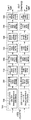
- FIG. 11 illustrates a demapping & decoding module according to an embodiment of the present invention.
- the demapping & decoding module illustrated in FIG. 11 corresponds to an embodiment of the demapping & decoding module described with reference to FIG. 8.
- the demapping & decoding module illustrated in FIG. 11 may perform a reverse operation of the coding and modulation module described with reference to FIG. 5.
- the coding and modulation module of the transmitting apparatus may independently process and process SISO, MISO, and MIMO schemes for respective paths to input data pipes. Accordingly, the demapping & decoding module illustrated in FIG. 11 may also include blocks for SISO, MISO, and MIMO processing of data output from the frame parser corresponding to the transmitting apparatus.
- the demapping & decoding module includes a first block 11000 for the SISO method, a second block 11100 for the MISO method, and a third for the MIMO method.
- a block 11200 and a fourth block 11300 for processing PLS pre / post information may be included.
- the demapping & decoding module illustrated in FIG. 11 is only an example, and according to the designer's intention, the demapping & decoding module may include only the first block 11000 and the fourth block 11300, and the second block. Only the first block 11100 and the fourth block 11300 may be included, or only the third block 11200 and the fourth block 11300 may be included. That is, according to the designer's intention, the demapping & decoding module can include blocks for processing each DP identically or differently.
- the first block 11000 is a block for SISO processing the input DP, a time de-ineterleaver block 11010, a cell de-interleaver block 11020, and a constellation demapper. (constellation demapper) block 11030, cell to bit mux block 11040, bit de-interleaver block 11050, and FEC decoder block 11060. can do.
- the time interleaver block 11010 may perform a reverse process of the time interleaver block 5060 described with reference to FIG. 5. That is, the time interleaver block 11010 may deinterleave the interleaved input symbols to their original positions in the time domain.
- the cell deinterleaver block 11020 may perform a reverse process of the cell deinterleaver block 5050 described with reference to FIG. 5. That is, the cell deinterleaver block 11020 may deinterleave the positions of the cells spread within one FEC block to the original positions.
- the constellation demapper block 11030 may perform a reverse process of the constellation demapper block 5040 described with reference to FIG. 5. That is, the constellation demapper block 11030 may demap the input signal of the symbol domain into the data of the bit domain. In addition, the constellation demapper block 11030 may perform a hard decision to output bit data according to the hard decision result, and to a soft decision value or a probabilistic value. Log-likelihood ratio (LLR) values of the corresponding bits can be output. If the rotated constellation is applied to obtain additional diversity gain at the transmitting end, the constellation demapper block 11030 may perform 2-D (Limensional) LLR demapping. In this case, when the LLR is calculated, the constellation demapper block 11030 may perform calculation to compensate for the delay value performed on the I or Q component by the transmitting apparatus.
- LLR Log-likelihood ratio
- the cell to bit mux block 11040 may perform a reverse process of the bit to cell demux block 5030 described with reference to FIG. 5. That is, the cell-to-bit mux block 11040 may restore the bit data mapped in the bit-to-cell demux block 5030 to the original bit stream form.
- the bit deinterleaver block 11050 may perform a reverse process of the bit interleaver block 5020 described with reference to FIG. 5. That is, the bit deinterleaver block 11050 may deinterleave the bit stream output from the cell-to-bit mux block 11040 in the original order.
- the FEC decoder block 11060 may perform an inverse process of the FEC encoder block 5010 described with reference to FIG. 5. That is, the FEC decoder block 11060 may correct an error generated on a transport channel by performing LDPC decoding and BCH decoding.
- the second block 11100 is a block for MISO processing the input DP, and as shown in FIG. 11, the time deinterleaver block, the cell deinterleaver block, and the constellation demapper block are the same as the first block 11000. , But may include a cell-to-bit mux block, a bit deinterleaver block, and an FEC decoder block, except that the MISO decoding block 1110 is further included. Like the first block 11000, the second block 11100 performs the same role from the time deinterleaver to the output, and thus description of the same blocks will be omitted.
- the MISO decoding block 11110 may perform a reverse process of the MISO processing block 5110 described with reference to FIG. 5.
- the MISO decoding block 11110 may perform Alamouti decoding.
- the third block 11200 is a block for MIMO processing the input DP, and as shown in FIG. 11, the time deinterleaver block, the cell deinterleaver block, and the constellation demapper block are the same as the second block 11100. It may include a cell-to-bit mux block, a bit deinterleaver block, and an FEC decoder block, but there is a difference in data processing in that it includes a MIMO decoding block 1112.
- the operations of the time deinterleaver, the cell deinterleaver, the constellation demapper, the cell-to-bit mux, and the bit deinterleaver blocks included in the third block 11200 are included in the first to second blocks 11000-11100. The operation and specific functions of the blocks may be different, but the basic role is the same.
- the MIMO decoding block 1112 may receive output data of the cell deinterleaver for m reception antenna input signals, and perform MIMO decoding as a reverse process of the MIMO processing block 5220 described with reference to FIG. 5.
- the MIMO decoding block 1210 may perform maximum likelihood decoding, or perform sphere decoding with reduced complexity in order to obtain the best decoding performance. Alternatively, the MIMO decoding block 1210 may perform MMSE detection or combine iterative decoding together to secure improved decoding performance.
- the fourth block 11300 is a block for processing PLS-pre / post information and may perform SISO or MISO decoding.
- the fourth block 11300 may perform a reverse process of the fourth block 5300 described with reference to FIG. 5.
- the operations of the time deinterleaver, the cell deinterleaver, the constellation demapper, the cell-to-bit mux, and the bit deinterleaver blocks included in the fourth block 11300 are included in the first to third blocks 11000-11200.
- the operation and specific functions of the blocks may be different, but the basic role is the same.
- the FEC decoder (11310) included in the fourth block (11300) may perform a reverse process of the shortened / punctured FEC encoder block 5310 described with reference to FIG. That is, the FEC decoder 11310 is shortened / punctured according to the length of the PLS data to perform de-shortening and de-puncturing on the received data, and then FEC decoding. Can be performed. In this case, since the FEC decoder used for the DP can be used for the PLS data in the same way, there is no need for a separate FEC decoding hardware for the PLS data, which has the advantage of easy system design and efficient coding.
- the aforementioned blocks may be omitted or replaced by other blocks having similar or identical functions according to the designer's intention.
- the demapping & decoding module can output DP and PLS information processed for each path to an output processor.
- FIG 12 illustrates an output processor according to an embodiment of the present invention.
- the output processor illustrated in FIG. 12 corresponds to an embodiment of the output processor described with reference to FIG. 8.
- the output processor illustrated in FIG. 12 receives a DP output from the demapping and decoding module and outputs a single output stream.
- the output processor may perform an inverse operation of the input formatting module described with reference to FIG. 2. .
- the output processor shown in FIG. 12 includes a BB scrambler block 12000, a padding removal block 12100, a CRC-8 decoder block 12200, and a BB frame processor ( BB frame processor) block 12300.
- the BB scrambler block 12000 may generate the same PRBS as used in the transmitter for the input bit stream, and perform descrambling by XORing the bit string.
- the padding remover block 12100 may remove the inserted padding bits as necessary at the transmitter.
- the CRC-8 decoder block 12200 may check a block error by performing CRC decoding on the bit stream received from the padding remover block 12100.
- the BB frame processor block 12300 may decode information transmitted in the BB frame header and restore MPEG-TS, IP stream (v4 or v6) or GS (Generic Stream) using the decoded information.
- the aforementioned blocks may be omitted or replaced by other blocks having similar or identical functions according to the designer's intention.
- FIG 13 illustrates an output processor according to another embodiment of the present invention.
- the output processor illustrated in FIG. 13 corresponds to an embodiment of the output processor described with reference to FIG. 8.
- the output processor illustrated in FIG. 13 corresponds to a case of receiving a plurality of DPs output from the demapping & decoding module.
- Decoding of a plurality of DPs is performed by merging and decoding common data and DPs associated therewith that can be commonly applied to a plurality of DPs, or when a receiving device uses a plurality of services or service components (SVCs). May include the case of decoding simultaneously).
- the output processor illustrated in FIG. 13 may include a BB descrambler block, a padding remover block, a CRC-8 decoder block, and a BB frame processor block as in the case of the output processor described with reference to FIG. 12.
- the operation and specific operation of the described blocks may be different, but the basic role is the same.
- the de-jitter buffer block 13000 included in the output processor illustrated in FIG. 13 stores delays arbitrarily inserted in a transmitter for sync between a plurality of DPs in a restored time to output (TTO) parameter. You can compensate accordingly.
- null packet insertion block 13100 may restore the null packet removed in the stream by referring to the recovered null packet (DNP) information and output common data.
- DNP recovered null packet
- the TS clock regeneration block 13200 may restore detailed time synchronization of an output packet based on input stream time reference (ISCR) information.
- ISCR input stream time reference
- the TS recombining block 13300 recombines the common data outputted from the null packet insertion block 13100 and the DPs associated with the original MPEG-TS, IP stream (v4 or v6) or GS (Generic). Stream to restore the output.
- TTO, DNP, and ISCR information may all be obtained through a BB frame header.
- the in-band signaling decoder block 13400 may restore and output in-band physical layer signaling information transmitted through a padding bit field in each FEC frame of the DP.
- the output processor shown in FIG. 13 performs BB descrambling of PLS-free information and PLS-post information input according to the PLS-free path and the PLS-post path, respectively, and decodes the descrambled data to perform original PLS decoding. You can restore the data.
- the recovered PLS data is transmitted to the system controller in the receiving device, and the system controller can supply the parameters required for the synchronization and demodulation module, the frame parsing module, the demapping & decoding module, and the output processor module of the receiving device.
- the aforementioned blocks may be omitted or replaced by other blocks having similar or identical functions according to the designer's intention.
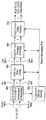
- FIG. 14 illustrates a coding and modulation module according to another embodiment of the present invention.
- the coding and modulation module illustrated in FIG. 14 corresponds to another embodiment of the coding and modulation module described with reference to FIGS. 1 and 5.
- the coding and modulation module illustrated in FIG. 14 includes a first block 14000 for the SISO scheme and a first scheme for the MISO scheme in order to adjust QoS for each service or service component transmitted through each DP.
- the coding and modulation module according to an embodiment of the present invention may include blocks for processing each DP identically or differently according to a designer's intention as described above.
- the first to fourth blocks 14000-14300 illustrated in FIG. 14 include blocks that are substantially the same as the first to fourth blocks 5000-5300 described with reference to FIG. 5.
- the functions of the constellation mapper block 14010 included in the first to third blocks 14000-14200 are included in the constellation mapper included in the first to third blocks 5000-5200 of FIG. 5. It differs from the function of the block 5040, and includes a rotation & I / Q interleaver block 1420 between the cell interleaver and the time interleaver of the first to fourth blocks 14000-14300. And the configuration of the third block 14200 for the MIMO scheme is different from that of the third block 5200 for the MIMO scheme shown in FIG. 5.
- a description of the same blocks as in FIG. 5 will be omitted and the description will be given based on the above-described differences.
- the constellation mapper block 14010 illustrated in FIG. 14 may map the input bit word into a complex symbol. However, unlike the constellation mapper block 5040 illustrated in FIG. 5, the constellation rotation may not be performed.
- the constellation mapper block 14010 illustrated in FIG. 14 may be commonly applied to the first to third blocks 14000-14200 as described above.
- the rotation and I / Q interleaver block 14020 independently interleaves the I (In-phase) component and the Q (Quadrature-phase) component of each complex symbol of the cell interleaved data output from the cell interleaver and outputs them in symbol units can do.
- the number of input data and output symbols of the rotation & I / Q interleaver block 14020 is two or more, which can be changed according to the designer's intention.
- the rotation & I / Q interleaver block 1420 may not interleave the I component.
- the rotation and I / Q interleaver block 1420 may be commonly applied to the first to fourth blocks 14000-14300 as described above. In this case, whether the rotation & I / Q interleaver block 1420 is applied to the fourth block 14300 for processing PLS-pre / post information may be signaled through the above-described preamble.
- the third block 14200 for the MIMO scheme may include a Q-block interleaver block 14210 and a complex symbol generator block 1422, as shown in FIG. have.
- the Q-block interleaver block 14210 may perform permutation on the parity part of the FEC block in which FEC encoding received from the FEC encoder is performed. In this way, the parity part of the LDPC H matrix can be made into a cyclic structure in the same way as the information part.
- the Q-block interleaver block 14210 can arrange the order of output bit blocks having the Q size of the LDPC H matrix. After permutation, row-column block interleaving may be performed to generate and output a final bit string.
- the complex symbol generator block 14220 may receive the bit strings output from the Q-block interleaver block 14210, and map the bit strings to complex symbols.
- the complex symbol generator block 1422 may output symbols through at least two paths. This can be changed according to the designer's intention.
- the aforementioned blocks may be omitted or replaced by other blocks having similar or identical functions according to the designer's intention.
- the coding and modulation module may output DP, PLS-free information, and PLS-post information processed for each path to the frame structure module.
- FIG. 15 illustrates a demapping & decoding module according to another embodiment of the present invention.
- the demapping & decoding module illustrated in FIG. 15 corresponds to another embodiment of the demapping & decoding module described with reference to FIGS. 8 and 11.
- the demapping & decoding module illustrated in FIG. 15 may perform a reverse operation of the coding and modulation module described with reference to FIG. 14.
- the demapping & decoding module includes a first block 15000 for the SISO method, a second block 15100 for the MISO method, and a third for the MIMO method.
- a block 15200 and a fourth block 15300 for processing PLS pre / post information may be included.
- the demapping & decoding module according to an embodiment of the present invention may include blocks for processing each DP identically or differently according to a designer's intention as described above.
- the first to fourth blocks 15000-15300 illustrated in FIG. 15 include blocks that are substantially the same as the first to fourth blocks 11000-11300 described with reference to FIG. 11.
- an I / Q deinterleaver & derotation block 15010 is included between the time deinterleaver and the cell deinterleaver of the first to fourth blocks 15000-15300.
- the constellation demapper block included in the first to third blocks 11000-11200 of FIG. 11 includes the functions of the constellation demapper block 15020 included in the first through third blocks 15000-15200.
- the structure of the third block 15200 for the MIMO scheme and the configuration of the third block 11200 for the MIMO scheme is different from the function of (11030).
- the description of the same blocks as in FIG. 11 will be omitted and the description will be given based on the above-described differences.
- the I / Q deinterleaver and derotation block 15010 may perform a reverse process of the rotation and I / Q interleaver block 1140 described with reference to FIG. 14. That is, the I / Q deinterleaver and derotation block 15010 may deinterleave the I and Q components transmitted by I / Q interleaving at the transmitter, respectively, and have a complex symbol having reconstructed I / Q components. You can derotate the output again.
- the I / Q deinterleaver and derotation block 15010 may be commonly applied to the first to fourth blocks 15000-15300 as described above. In this case, whether the I / Q deinterleaver and derotation block 15010 is applied to the fourth block 15300 for processing the PLS-pre / post information may be signaled through the above-described preamble.
- the constellation demapper block 15020 may perform a reverse process of the constellation mapper block 14010 described with reference to FIG. 14. That is, the constellation demapper block 15020 may perform demapping on cell deinterleaved data without performing derotation.
- the third block 15200 for the MIMO scheme may include a complex symbol parsing block 15210 and a Q-block deinterleaver block 15220, as shown in FIG. 15. Can be.
- the complex symbol parsing block 15210 may perform an inverse process of the complex symbol generator block 1422 described with reference to FIG. 14. In other words, the complex data symbol may be parsed, demapping into bit data, and output. In this case, the complex symbol parsing block 15210 may receive complex data symbols through at least two paths.
- the Q-block deinterleaver block 15220 may perform a reverse process of the Q-block interleaver block 14210 described with reference to FIG. 14. That is, the Q-block deinterleaver block 15220 restores the Q size blocks by row-column deinterleaving, and then restores the order of each permutated block in the original order. By parity deinterleaving, the parity bits may be restored to their original positions and output.
- the aforementioned blocks may be omitted or replaced by other blocks having similar or identical functions according to the designer's intention.
- the demapping & decoding module can output DP and PLS information processed for each path to the output processor.
- the broadcast signal transmission apparatus or the above-described waveform transform block 7200 inserts pilots to a signal frame output from the frame structure module 1200 and uses transmission parameters.
- Broadcast signals may be OFDM modulated.
- Transmission parameters according to an embodiment of the present invention may be referred to as OFDM parameters.
- the present invention proposes transmission parameters that can maximize transmission efficiency and apply to various reception scenarios while satisfying the in-band spectrum mask criterion for the next generation broadcast transmission / reception system.
- FIG. 16 illustrates a table showing information related to a reception mode according to an embodiment of the present invention.
- the table of FIG. 16 includes a network configuration according to a reception mode of a next generation broadcast transmission / reception system.
- the reception mode according to an embodiment of the present invention may be classified into a fixed rooftop, a handheld portable environment, and a handheld mobile environment.
- a representative channel can be determined.
- the broadcast signal transmission apparatus may determine the transmission mode according to the reception mode described above. That is, the broadcast signal transmission apparatus according to an embodiment of the present invention may process and transmit broadcast service data in a non-MIMO method (MISO and SISO method) or a MIMO method according to the characteristics of the broadcast service, that is, the reception mode. Accordingly, the broadcast signal according to each transmission mode may be transmitted and received through a transmission channel corresponding to the corresponding processing scheme.
- MISO and SISO method non-MIMO method
- MIMO method MIMO method according to the characteristics of the broadcast service
- each transmission mode may be distinguished and transmitted in units of signal frames according to an embodiment.
- each signal frame may include a plurality of OFDM symbols, and each OFDM symbol may include a plurality of data symbols for transmitting data corresponding to the above-described preamble (or preamble symbols) and a broadcast signal.
- the left column of the table of FIG. 16 shows the three reception modes described above.
- the broadcast signal reception apparatus may receive a broadcast signal through a rooftop antenna corresponding to a height of 10m or more above the ground. Therefore, since the direct path is secured, the Rician channel is typically used, the influence of the Doppler is small, and the delay spread of the channel according to the use of the directional antenna is used. The range of may be limited.
- the broadcast signal receiving apparatus may receive a broadcast signal through an omni-directional antenna corresponding to a height of 1.5 m or less above the ground.
- a Rayleigh channel is typically used as a transmission channel environment by reflected waves, and a range of delay spread of a channel longer than that of the directional antenna can be secured.
- the handheld portable environment can support a low level Doppler environment in consideration of mobility of walking level as an indoor / outdoor reception environment.
- the handheld portable environment may be classified into a fixed environment and a pedestrian environment.
- Handheld mobile environments can support high Doppler environments by considering not only the walking level of the receiver, but also the speed at which the vehicle travels, such as cars and trains.
- the right side of the table of Fig. 16 shows the network configuration according to each reception mode.
- the network configuration refers to a network structure, and the network configuration according to an embodiment of the present invention is a single frequency network (MFN) consisting of a plurality of frequencies and a single frequency (SFN) consisting of one frequency according to frequency operation in a network. ) Can be distinguished.
- MFN single frequency network
- SFN single frequency
- MFN is a network structure for transmitting broadcast signals using many frequencies in a large area.
- a plurality of transmission towers or broadcast signal transmitters located in the same area may transmit broadcast signals through different frequencies. .
- a delay spread due to natural echo generated by the terrain, features, etc. in the network may be formed.
- the broadcast signal receiver since the broadcast signal receiver receives only one radio wave, the reception quality may be determined according to the magnitude of the received radio wave.
- SFN refers to a network structure in which a plurality of broadcast signal transmitters located in the same region transmit the same broadcast signal through the same frequency.
- a maximum delay spread of a transmission channel may occur due to an additional man-made echo.
- the reception quality may be affected by the mutual ratio between the radio wave to be received and the radio wave of the disturbing frequency, the delay time, and the like.
- the value of the guard interval is determined in consideration of the maximum delay spread of the transmission channel in order to minimize the inter symbol interference. Since the guard interval is redundant data additionally inserted into the transmitted broadcast signal, the overall symbol duration should be designed to minimize the SNR loss in consideration of the overall transmission power efficiency.
- FIG. 17 illustrates a bandwidth of a broadcast signal according to an embodiment of the present invention.
- the bandwidth of a broadcast signal is the same as the waveform transform bandwidth, and the waveform transform bandwidth corresponds to a channel bandwidth and a spectrum mask.
- the channel bandwidth may include a signal bandwidth.
- the transmission parameter according to an embodiment of the present invention maximizes transmission efficiency within the bandwidth of the corresponding broadcast signal while satisfying a spectrum mask required to minimize interference of adjacent channels within the corresponding channel bandwidth allocated in the next generation broadcast transmission / reception system. It must be designed to In addition, since the above-described waveform generation module 1300 may use a plurality of carriers to transform the input signal, the transmission parameter according to an embodiment of the present invention may be used for transformation in a waveform transform bandwidth. The interval of each subcarrier may be adjusted according to the number of subcarriers used, the total symbol length may be determined in the time domain, and the transmission mode suitable for the reception scenario of the next generation broadcast transmission / reception system may be classified and designed based on this.
- FIG. 18A is a table showing values of guard intervals as transmission parameters according to the reception mode and network configuration described above
- FIG. 18B is a table illustrating vehicle speeds as transmission parameters according to the reception mode and network configuration described above. Table shows the values of vehicle speed).
- the guard interval may be designed in consideration of the maximum delay spread based on the network configuration and the environment of the reception antenna according to the reception scenario.
- the vehicle speed as a transmission parameter may be designed and determined by reflecting the environment of the network configuration and the reception antenna according to the classification of the reception scenario.
- a method of setting a guard interval (or elementary guard interval) and vehicle speed and optimizing transmission parameters using an optimization scaling factor or an optimization scaling factor for design optimization of a next generation broadcast transmission / reception system Suggest.
- a symbol (or OFDM symbol) included in a signal frame according to an embodiment of the present invention may be transmitted during a specific duration.
- Each symbol may also include a usable part corresponding to an active symbol duration length and a guard interval area corresponding to a guard interval.
- the guard interval region may be located in front of the use pool region.
- the guard intervals according to the embodiment of the present invention correspond to NG_a1, NG_a2,... , NG_b1, NG_b2,... , NG_c1, NG_c2,... , NG_d1, NG_d2,... , NG_e1, NG_e2,... , NG_f1, NG_f2,... , NG_g1, NG_g2,... , NG_h1, NG_h2,... It can be set to.
- Guard intervals (a) and (b) shown in (A) mean an embodiment of the guard interval that can be applied to the next generation broadcast transmission and reception system according to an embodiment of the present invention.
- the guard interval (a) is 25us
- the guard interval (b) is an embodiment in the case of setting the 30us as the elementary guard interval
- the optimization according to the network structure and the optimization for the transmission efficiency and SNR loss of the transmission signal The example in which the scaling factor is set to Lalpha1, Lalpha2, Lbeta1, and Lbeta2 is shown.
- the vehicle speed according to the embodiment of the present invention is quasi static, ⁇ Vp_a1 km / h, ⁇ Vp_b1 km / h, Vm_a1 km / h to Vm_a2 km / h, for each of the above-described reception modes. It may be set to Vm_b1 km / h ⁇ Vm_b2 km / h.
- the vehicle speed (a) shown in (B) is an embodiment of the vehicle speed that can be applied to the next-generation broadcast transmission and reception system according to an embodiment of the present invention quasi-static, 3km / h, 3km according to each reception scenario Optimizing scaling factor, Valpha1, Valpha2, Vbeta1, for setting the / h ⁇ 200km / h as the elementary vehicle speed and optimizing the network structure and optimizing the transmission efficiency and time-varying channel estimation of the transmission signal. Shows an example in which Vbeta1 is set.
- eBW effective signal bandwidth
- Nwaveform_scaling shown in Equation 1 means a waveform scaling factor
- Npilotdensity means a pilot density scaling factor
- NeBW means an effective signal bandwidth scaling factor
- ⁇ denotes an additional bandwidth.
- Fs also means sampling frequency.
- the above-described factors are used as optimization parameters (or optimization parameters) to determine the eBW optimized for the spectral mask according to the channel bandwidth.
- optimization parameters or optimization parameters
- the waveform scaling factor is a scaling value according to a bandwidth of a carrier used for waveform transformation.
- the waveform scaling factor according to an embodiment of the present invention is an arbitrary proportional to the length of a nonquispaced fast Fourier transform (NFFT) for OFDM. It can be set to a value.
- NFFT nonquispaced fast Fourier transform
- the pilot density scaling factor may be set according to the density of the reference signal as a value set according to a predetermined position of the reference signal inserted in the reference signal insertion and PAPR reduction block 7100.
- the effective signal bandwidth scaling factor is set to any value that can maximize the bandwidth of the transmission signal while satisfying the specification of the spectral mask within the transmission channel bandwidth. This allows you to design optimized eBWs.
- the additional bandwidth factor may be set to an arbitrary value to adjust additional information and structure required in the transmission signal bandwidth.
- the additional bandwidth factor may also insert a reference signal to insert an edge of the spectrum. (edge) can be used to improve channel estimation performance.
- NoC Number of Carrier is the total number of carriers transmitted through the signal bandwidth, it can be represented by the formula contained in the braces of the equation.
- the broadcast signal transmission apparatus may use the waveform transform bandwidth as a transmission parameter for additionally optimizing eBW according to the number of subcarriers used for modification.
- the broadcast signal transmission apparatus may use the above-described effective signal bandwidth scaling factor as a transmission parameter for optimizing eBW.
- the effective signal bandwidth scaling factor may be set to a maximum value optimized for the spectral mask by extending the pilot density unit of the preset reference signal.
- the apparatus for transmitting broadcast signals according to an embodiment of the present invention adjusts the waveform transform bandwidth, that is, the sampling frequency, of the ambiguities that can be generated according to the pilot density unit, thereby applying the effective signal bandwidth scaling factor to the spectrum mask. You can decide.
- 19 is a table showing transmission parameters for optimizing eBW according to an embodiment of the present invention.
- the transmission parameters illustrated in FIG. 19 are transmission parameters for optimizing eBW of a next generation broadcasting system applying the OFDM scheme while complying with a Federal Communications Commission (FCC) spectrum mask for a 6 MHz channel bandwidth.
- FCC Federal Communications Commission
- (A) is a table showing transmission parameters (example (A)) set for the guard interval (a) and the vehicle speed (a) according to the embodiment of the present invention described above, and (B) Table showing transmission parameters (example (B)) set for the guard interval (b) and vehicle speed (b) according to an embodiment of the invention.
- (A ') is a table showing an embodiment of the GI duration for combining the FFT and the GI mode set in accordance with the above-mentioned (A)
- (B') is the FFT (NFFT) set in accordance with the above-mentioned (B) and Table showing an embodiment of a GI duration for combining GI modes.
- the transmission parameters shown in (A) and (B) have been set for three FFT modes of 8K, 16K and 32K, but are applicable even when the FFT mode is 1K / 2K / 4K / 64K. Also, (A) and (B) illustrate embodiments of optimization scaling factors that can be applied according to each FFT mode.
- the broadcast signal transmission apparatus may insert a reference signal into a time and frequency domain in consideration of the transmission parameters described in (A) and (B), a reception scenario, and a network configuration. It can be used as additional information for synchronization and channel estimation.
- the broadcast signal transmission apparatus may set the density (Npilotdensity) of the reference signal and the optimized eBW in consideration of the ratio of the channel estimation range to the guard interval.
- the waveform scaling factor according to an embodiment of the present invention may be determined in proportion to the FFT size according to each FFT mode.
- the waveform transform bandwidth that is, the sampling frequency is adjusted. It is possible to determine the maximum signal bandwidth that does not exceed the spectral mask.
- the sampling frequency may be used to determine the optimized signal bandwidth and to determine the OFDM symbol duration and subcarrier spacing. Accordingly, the sampling frequency may be determined in consideration of not only the transmission channel and reception scenario of the guard interval and vehicle speed described above, but also the efficiency and SNR loss of the transmission signal.
- (A) of the figure shows an embodiment in which the value of Fs is 221/32 MHz
- (B) shows an embodiment in which the value of Fs is (1753/256) MHz.
- Fc shown in (A) and (B) means the central frequency (central frequency) of the RF signal
- Tu means the active symbol duration.
- 20 is a table showing transmission parameters for optimizing eBW according to another embodiment of the present invention.
- (A) is a table showing the same transmission parameters (example (A)) in FIG. 19A.
- (B) is a table showing transmission parameters (example (B-1)) set for the guard interval (b) and the vehicle speed (b) as another embodiment of the table of FIG. 19B.
- (A ') is a table showing an embodiment of the GI duration for combining the FFT and GI mode set according to (A), and (B') shows the combination of the FFT and GI mode set according to (B) described above. Table showing an embodiment of a GI duration.
- each transmission parameter shown in FIG. 20 are the same as in FIG. 19 except that the Tu value in the center column of FIG. 20B is changed to 2392.6 unlike FIG. Omit.
- 21 is a table showing transmission parameters for optimizing eBW according to another embodiment of the present invention.
- (A) is a table which shows the other Example of (B) demonstrated in FIG. Specifically, (A) is a table showing transmission parameters (example (B-2)) when the value of Fs is 219/32 MHz.
- (B) is a table showing an embodiment of the GI duration for combining the FFT and the GI mode set according to the above-mentioned (A).
- the transmission parameters shown in (A) are different in that the fc and Tu values are increased, but the eBW values are decreased, compared with the transmission parameters shown in FIG.
- the eBW value may be a value that can be set as a factor with respect to the channel bandwidth.
- 22 is a table showing transmission parameters according to another embodiment of the present invention.
- FIG. 22A shows a derivation of a scaling factor and an Fs value corresponding to channel bandwidths of 5, 7, and 8 MHz of the above-described embodiments by a product of a scaling factor calculated based on an Fs value of 6 MHz. Results are shown.
- the scaling factor corresponds to the ratio of the channel bandwidth.
- FIG. 22B illustrates a table showing transmission parameters for optimizing the eBW described with reference to FIGS. 19 to 21.
- the table located at the top of (B) shows transmission parameters corresponding to channel bandwidths of 5, 6, 7, and 8 MHz of the example (A) described with reference to FIGS. 19 and 20.
- the table located in the middle of (B) shows transmission parameters corresponding to channel bandwidths of 5, 6, 7, and 8 MHz in the example (B-1) described with reference to FIG. 20.
- the table located at the bottom of (B) shows transmission parameters corresponding to channel bandwidths of 5, 6, 7, and 8 MHz in the example (B-2) described with reference to FIG. 21.
- the second row of (A) shows the result obtained by ringing the setting of the Fs value corresponding to each channel bandwidth in the table located at the top of (B) by the product of the scaling factor calculated based on the Fs value of 6MHz.
- the third row of (A) shows the result obtained by ringing the setting of the Fs value corresponding to each channel bandwidth in the table located in the center of (B) by the product of the scaling factor calculated based on the Fs value of 6 MHz.
- the third row of (A) shows the result of annularly deriving the setting of the Fs value corresponding to each channel bandwidth from the table located at the bottom of (B) by the product of the scaling factor calculated based on the Fs value of 6MHz.
- FIG. 23 is a graph illustrating Power Spectral Density (PSD) of a transmission signal according to an embodiment of the present invention.
- PSD Power Spectral Density
- the left graph of (A) shows the PSD of the transmission signal optimized for the FCC spectral mask of the example (A) described in FIGS. 19 to 20, and the right graph of (A) shows the result of enlarging a part of the left graph. .
- the left graph of (B) shows the PSD of the transmission signal optimized for the FCC spectral mask of the example (B) described in FIG. 19, and the right graph of (B) shows an enlarged part of the left graph.
- each graph plots the PSD of the transmitted signal derived using a line indicating the specification of the FCC spectral mask and transmission parameters corresponding to 8K, 16K and 32K, respectively. Indicates lines that represent.
- the PSD of each transmission signal at a breakpoint of the target spectral mask should not exceed the threshold of the spectral mask.
- the PSD of the out of band emission transmission signal may be band-limited by the baseband filter.
- 24 is a table illustrating information related to a reception mode according to another embodiment of the present invention.
- FIG. 24 corresponds to another embodiment of a table illustrating information related to the reception mode described in FIG. 16, and illustrates a table showing network configuration, FFT value (NFFT), guard interval, and vehicle speed corresponding to each reception mode. Guard interval and vehicle speed values are the same as described with reference to FIG. 18.
- a large FFT such as 16K and 32K can be used.
- transmission can be performed to increase the efficiency of data with respect to redundancy ratios such as guard intervals and reference signals suitable for network configuration.
- an FFT such as 8K, 16K, and 32K, which supports a low level Doppler environment and can support high frequency sensitivity, can be used.
- guard interval according to an embodiment of the present invention may be set to support the same level of coverage in consideration of the network configuration of each reception.
- the broadcast signal transmission apparatus or the above-described waveform transform block 7200 inserts pilots to a signal frame output from the frame structure module 1200 and uses transmission parameters.
- Broadcast signals may be OFDM modulated.
- Various cells in an OFDM symbol may be modulated using reference information, ie pilots.
- the pilot may be used to transmit information already known by the broadcast signal receiver, and each pilot may be transmitted at a power level specified according to the pilot pattern.
- Pilots according to an embodiment of the present invention may be used for frame synchronization, frequency and time synchronization, channel estimation, and the like.
- the pilot mode according to an embodiment of the present invention is information for indicating a pilot set for transmitting an optimized broadcast signal and reducing overhead of transmission parameters according to the above-described reception environment.
- the pilot pattern according to an embodiment of the present invention may be variously set according to the reception mode and the FFT size described above.
- the pilot pattern and pilot mode described below may be equally applied to the above-described reception mode and network configuration.
- a pilot pattern and a pilot mode according to an embodiment of the present invention may be applied to data symbols in a signal frame.
- 25 illustrates a relationship between a maximum channel estimation range and a guard interval according to an embodiment of the present invention.
- Equation 1 is for determining an effective signal bandwidth of a transmission signal, and a pilot density scalable factor may be used as an optimization parameter.
- Equation 1 may be determined by optimizing values of pilot density, Dx, and Dy related to time, frequency placement, and data efficiency of the pilot signal for SISO channel estimation.
- the pilot density corresponds to the product of the distance between pilots in the time and frequency domain, and the pilot overhead occupied by the pilot in the symbol corresponds to the inverse of the pilot density.
- Dx means the distance between pilots in the frequency domain
- Dy means the distance between pilots in the time domain.
- Dy can be used to determine the maximum tolerable doppler speed. Therefore, Dy may be determined as an optimized value reflecting the vehicle speed determined according to the classification of the reception scenario.
- the values of Dx and Dy may be set in consideration of the transmission efficiency along with the state of the transmission channel.
- the transmission channel is set differently according to the reception mode described above. Can be.
- the maximum channel estimation range TChEst illustrated in FIG. 25 may be determined by a value obtained by dividing the above-described transmission parameter Tu by Dx.
- the maximum channel estimation range may include a guard interval having a predetermined length, a pre-echo region and a post-echo region.
- the ratio of the given guard interval to the maximum channel estimation range means the margin of the channel estimation range from which the guard interval can be estimated. If the margin value of the channel estimation range exceeds the length of the guard interval, the excess values may be assigned to the pre echo region and the post echo region, respectively.
- the pre-echo and post-echo areas can be used to estimate the channel impulse response beyond the length of the guard interval, and can be used as an area used for estimating or compensating for timing errors that may occur during synchronization. have. However, larger margins can increase pilot overhead and reduce transmission efficiency.
- 26 and 27 show tables defining pilot parameters according to the above-described guard intervals (A) and (B) and vehicle speed. Each drawing is demonstrated below.
- FIG. 26 is a diagram illustrating a table defining pilot parameters according to an embodiment of the present invention.
- FIG. 26 is a diagram illustrating pilot parameters according to the above-described guard interval (A) and vehicle speed, (A) is a table showing pilot patterns used for SISO and MIXO transmission channels, and (B) is a table for SISO and MIXO transmission channels. The configuration of the pilot pattern used for, (C) is a table showing the configuration of the pilot pattern used for the MIXO transmission channel.
- (A) shows pilot patterns determined for each pilot density value and Dx and Dy values defined for each of the SISO and MIXO transport channels for each pilot pattern.
- the pilot pattern according to an embodiment of the present invention may be represented as PP5-4, where the first number means the value of Dx and the second number means the Dy value.
- PP5-4 the first number means the value of Dx
- the second number means the Dy value.
- a smaller value of Dx can support longer delay spreads, and a smaller value of Dy can adapt to a faster Doppler environment.
- (B) and (C) are tables showing the pilot pattern configuration according to the guard interval duration and the FFT value. Specifically, the numbers shown in the first row of the tables shown in (B) and (C) indicate the duration of the guard interval, and the first column indicates the FFT value (NFFT) described with reference to FIGS. 19 to 22.
- (B) and (C) are the same in that they represent the configuration of the pilot pattern in the case of MIXO, but (B) represents the pilot pattern of the version (MIXO-1) with a larger pilot overhead, and (C) The difference is that it represents the pilot pattern of the less mobile version (MIXO-2).
- the duration of the guard interval shown in (B) and (C) described above is the same concept as the length of the guard interval described in FIG. 25, and has values of 25us, 50us, 100us, 200us, and 400us in consideration of the maximum delay spread.
- the FFT size may be 8K, 16K, and 32K.
- Dx may have a value of 5, 10, 20, 40, 80, 160 in consideration of the duration of the guard interval and the FFT size.
- the elementary Dx value 5, which is a basic value may be defined as a value that may vary according to each transmission mode, and is set in consideration of the margin of the channel estimation range described above by about 20%. You can do
- the margin value of the channel estimation range of the present invention may be adjusted by using values of Lalpha1 in MFN and Lalpha2 in SFN.
- a value of Dy may be set according to a reception scenario and a transmission mode according to a reception scenario. Therefore, the Dy value may be set to different values depending on whether the SISO or MIXO transmission channel is used. As shown in the figure, Dy may be set to a value of 2, 4, and 8 in the case of an SISO transport channel.
- the Dy value may be set differently according to each version.
- the larger pilot overhead (MIXO-1) is intended to increase pilot overhead to support the same maximum delay spread and maximum mobile speed in the same network configuration as the SISO transport channel, in which case the value of Dy is equal to the SISO transport channel. Similarly, it may be set to a value of 2, 4 and 8. That is, the MIXO-1 transport channel may be applied in the handheld portable environment or the handheld mobile environment.
- MIXO-2 The less mobile version (MIXO-2) is intended to guarantee the same coverage and capacity as the SISO transport channel, even though it is somewhat of a loss in mobile speed support, in which case the value of Dy is 4 It can be set to a value of 8,16.
- 27 is a diagram illustrating a table defining pilot parameters according to another embodiment of the present invention.
- FIG. 27 is a diagram illustrating pilot parameters according to the above-described guard interval (B) and vehicle speed
- (A) is a table showing pilot patterns used for SISO and MIXO transmission channels
- (B) is a table for SISO and MIXO transmission channels.
- (C) is a table showing the configuration of the pilot pattern used for the MIXO transmission channel.
- the structure and position of the pilot for MIXO (MISO, MIMO) transmission channel estimation can be set through the above-described pilot pattern.
- a null encoding and a hardware encoding scheme may be used as pilot encoding schemes for separating transport channels.
- the following equation is an equation representing a nulling encoding scheme.
- the nulling encoding method Since the nulling encoding method has no mutual channel interference in estimating each channel, errors in channel estimation can be minimized and it is easy to estimate an independent channel when using symbol timing synchronization. However, since the gain of the pilot must be amplified to obtain the channel estimation gain, the influence of Inter Channel Interference (ICI) of adjacent data by the pilot according to the time-varying channel is relatively large, and the position of the pilot allocated to each channel according to the pilot arrangement If not the same may have the disadvantage that the SNR of the effective data can be changed for each symbol.
- the MIXO-1 pilot pattern according to the embodiment of the present invention described above may be advantageously used even in the case of a nulling encoding scheme. Details will be described later.
- the following equation is an equation representing a nulling encoding scheme.
- channel estimation can be performed through simple linear calculation, and the gain of noise average effect can be obtained compared to the nulling encoding method.
- errors in cross-channel estimation may affect other channels, and ambiguity may occur in symbol timing synchronization using a pilot.
- the apparatus for transmitting broadcast signals according to an embodiment of the present invention may set the above two encoding schemes as MIXO pilot encoding schemes according to a reception scenario and a state of a transmission channel according to a preset mode.
- the broadcast signal receiving apparatus according to an embodiment of the present invention may perform channel estimation through a preset mode.
- the pilot pattern shown in FIG. 28 represents the pattern of the SISO pilot when the pilot density described in FIG. 27 is 32.
- the pilot may be inserted in the data symbol region of the signal frame.
- the horizontal axis of the pilot pattern shown in the figure represents the frequency axis, and the vertical axis represents the time axis.
- pilots consecutively arranged at both ends of the pilot pattern are reference signals inserted to compensate for distortion at the spectral edges generated during channel estimation.
- (A) shows the case where the pilot pattern is PP4-8
- (B) shows the case where the pilot pattern is PP8-4
- (C) shows the case where the pilot pattern is PP16-2. That is, as shown in (A), the pilot may be input periodically in units of four carriers on the frequency axis, and each pilot may be input in units of eight symbols on the time axis.
- (B) and (C) also show patterns of pilots input in the same manner.
- the pilot pattern for the other pilot density described with reference to FIG. 27 may be represented by adjusting the values of Dx and Dy in this figure.
- the pilot pattern shown in FIG. 29 represents the pattern of the MIXO-1 pilot when the pilot density described in FIG. 27 is 32, and indicates the pilot pattern when there are two transmit antennas.
- pilots consecutively arranged at both ends of the pilot pattern are reference signals inserted to compensate for distortion at the spectral edges generated during channel estimation.
- (A) shows the case where the pilot pattern is PP4-8
- (B) shows the case where the pilot pattern is PP8-4
- (C) shows the case where the pilot pattern is PP16-2.
- each MIXO transport channel in order to distinguish each MIXO transport channel, it may be an embodiment to arrange pilots transmitted on each transport channel to be adjacent in the frequency domain. In this case, the number of pilots allocated to two transmission channels in one OFDM symbol is the same.
- the MIXO-1 pilot pattern according to an embodiment of the present invention, even if a reference signal for synchronizing is arranged, a data signal is arranged after the pilot for channel estimation to signal the same carrier. It has the advantage that there is no effect on the synchronization estimation performance by reducing the correlation between the two.
- the broadcast signal transmitting apparatus performs pilot encoding by the above-described nulling encoding method, it is possible to transmit a broadcast signal having the same transmit power to each transmit antenna. Therefore, there is an advantage in that the broadcast signal can be transmitted without a separate device or module for compensating for the variation of the transmission signal. That is, when using the MIXO-1 pilot pattern according to an embodiment of the present invention, the channel estimation performance in the broadcast signal receiving apparatus is adjusted by adjusting the power of the pilot according to the pilot encoding scheme without being affected by the pilot encoding scheme. It can be maximized.
- the pilot pattern for the other pilot density described with reference to FIG. 27 may be represented by adjusting the values of Dx and Dy in this figure.
- FIG. 30 illustrates a MIXO-2 pilot pattern according to an embodiment of the present invention.
- the pilot pattern shown in FIG. 30 shows the pattern of the MIXO-2 pilot when the pilot density described in FIG. 27 is 32 and indicates the pilot pattern when there are two transmit antennas.
- pilots consecutively arranged at both ends of the pilot pattern are reference signals inserted to compensate for distortion at the spectral edges generated during channel estimation.
- (A) shows the case where the pilot pattern is PP4-16
- (B) shows the case where the pilot pattern is PP8-8
- (C) shows the case where the pilot pattern is PP16-4.
- the MIXO-2 pilot pattern according to an embodiment of the present invention has a structure of lowering mobility supported by half instead of supporting the same capacity, pilot overhead, and coverage as the SISO transport channel.
- the MIXO-2 pilot pattern maximizes data transmission efficiency in the reception scenario where UHDTV service should be supported. Can be used for
- the pilot pattern for the other pilot density described with reference to FIG. 27 may be represented by adjusting the values of Dx and Dy in this figure.
- 31 is a flowchart of a broadcast signal transmission method according to an embodiment of the present invention.
- the broadcast signal transmission apparatus may encode DP data corresponding to a DP for transmitting at least one broadcast service or broadcast service component (S31000).
- the at least one broadcast service may correspond to any one of a broadcast service for a fixed receiver or a broadcast service for a mobile receiver, and each broadcast service may be transmitted in a frame unit.
- the specific encoding method is as described above.
- the apparatus for transmitting broadcast signals according to an embodiment of the present invention may map encoded DP data to constellations (S31100). Thereafter, the apparatus for transmitting broadcast signals according to an embodiment of the present invention may time interleave the mapped DP data (S31200). As described above, the DP data may be processed for each DP path, and a specific interleaving method is as described above.
- the broadcast signal transmission apparatus may generate at least one signal frame including time interleaved DP data (S31300).
- the DP data processed in each path may be mapped to the data symbol region of the signal frame.
- the apparatus for transmitting broadcast signals according to an embodiment of the present invention may insert at least one or more pilots according to at least one pilot pattern in the generated at least one signal frame (S31400).
- at least one pilot pattern may be set differently for a broadcast service for a fixed receiver or a broadcast service for a mobile receiver, and may be determined according to the size of the FFT and the size of the guard interval. Details are as described above.
- the apparatus for transmitting broadcast signals may perform OFDM modulation on the generated at least one signal frame using OFDM parameters (S31500).
- OFDM parameters may be determined according to the FFT size. Details are as described above.
- the apparatus for transmitting broadcast signals may transmit at least one broadcast signal including at least one modulated signal frame (S31600).
- 32 is a flowchart of a broadcast signal receiving method according to an embodiment of the present invention.
- the broadcast signal receiving apparatus may receive at least one broadcast signal and OFDM demodulate the received at least one broadcast signal using OFDM parameters (S32000).
- OFDM parameters may be determined according to the FFT size. Details are as described above.
- the broadcast signal receiving apparatus may detect at least one or more pilots included in the demodulated at least one broadcast signal (S32100).
- at least one pilot may be inserted according to at least one pilot pattern, and may be differently set for a broadcast service for a fixed receiver or a broadcast service for a mobile receiver, and the size of an FFT And the size of the guard interval. Details are as described above.
- the apparatus for receiving broadcast signals may obtain at least one signal frame from at least one demodulated broadcast signal (S32200).
- DP data may be mapped to a data symbol region.
- the broadcast signal receiving apparatus may time deinterleave DP data included in at least one or more signal frames obtained.
- the apparatus for receiving broadcast signals may demap the deinterleaved DP data (S32400) and decode the demapped DP data to obtain a desired service or service component (S32500).
- each DP data may be processed through a corresponding DP path, and specific processing is as described above.
- the present invention may be applied in whole or in part to a digital broadcast transmission / reception apparatus or system.
Abstract
An apparatus for transmitting a broadcast signal according to one embodiment of the present invention comprises: an encoder for encoding data pipe (DP) data corresponding to a DP which transmits at least one broadcast service or broadcast service component; a mapper for mapping the encoded DP data on a constellation; a time interleaver for time-interleaving the mapped DP data; a frame builder for generating at least one signal frame including the time-interleaved DP data; a pilot inserting unit for inserting at least one pilot within the at least one generated signal frame, according to at least one pilot pattern; an OFDM modulator for OFDM-modulating the at least one generated signal frame using OFDM parameters; and a transmitter for transmitting at least one broadcast signal including the at least one modulated signal frame.
Description
본 발명은 방송 신호를 송신하는 방송 신호 송신 장치, 방송 신호를 수신하는 방송 신호 수신 장치 및 방송 신호를 송신하고 수신하는 방법에 관한 것이다.The present invention relates to a broadcast signal transmission apparatus for transmitting a broadcast signal, a broadcast signal reception apparatus for receiving a broadcast signal, and a method for transmitting and receiving a broadcast signal.
아날로그 방송 신호에 대한 송출의 중단 시점이 다가오면서, 디지털 방송 신호를 송수신하기 위한 다양한 기술들이 개발되고 있다. 디지털 방송 신호는 아날로그 방송 신호에 비해 대용량의 비디오/오디오 데이터를 포함할 수 있으며, 비디오/오디오 데이터 외에도 다양한 부가 데이터를 포함할 수 있다. As the point of stopping transmission of the analog broadcast signal is approaching, various technologies for transmitting and receiving digital broadcast signals have been developed. The digital broadcast signal may include a larger amount of video / audio data than the analog broadcast signal, and may include various additional data in addition to the video / audio data.
즉, 디지털 방송을 위한 디지털 방송 시스템은 HD(High Definition)급의 영상과 다채널의 음향 및 다양한 부가 서비스를 제공할 수 있다. 다만, 고용량의 데이터 전송을 위한 데이터 전송 효율, 송수신 네트워크의 강인성(robustness) 및 모바일 수신 장비를 고려한 네트워크의 유연성(flexibility)은 여전히 개선해야 하는 과제이다.That is, the digital broadcasting system for digital broadcasting may provide HD (High Definition) level images, multi-channel sound, and various additional services. However, data transmission efficiency for high-capacity data transmission, robustness of the transmission / reception network, and flexibility of the network considering mobile reception equipment still need to be improved.
따라서 본 발명의 목적은 차세대 방송 서비스(future broadcast service)를 위한 방송 신호를 전송하고 수신할 수 있는 방송 신호 송신 장치, 방송 신호 수신 장치, 그리고 차세대 방송 서비스를 위한 방송 신호를 송신하고 수신하는 방법을 제공하는데 있다.Accordingly, an object of the present invention is to provide a broadcast signal transmitting apparatus capable of transmitting and receiving broadcast signals for future broadcast services, a broadcast signal receiving apparatus, and a method of transmitting and receiving broadcast signals for next-generation broadcast services. To provide.
본 발명의 목적은 서로 다른 두 개 이상의 방송 서비스를 제공하는 방송 송수신 시스템의 데이터를 시간 영역에서 멀티플렉싱하여 동일한 RF 신호 대역폭(signal bandwidth)을 통하여 전송할 수 있는 방송 신호 송신 장치 및 방송 신호 송신 방법 및 이에 대응하는 방송 신호 수신 장치 및 방송 신호 수신 방법을 제공하는 데에 있다.An object of the present invention is to provide a broadcast signal transmission apparatus and a broadcast signal transmission method capable of transmitting data through a same RF signal bandwidth by multiplexing data of a broadcast transmission / reception system providing two or more different broadcast services in a time domain, and There is provided a corresponding broadcast signal receiving apparatus and broadcast signal receiving method.
본 발명의 또 다른 목적은 서비스에 해당하는 데이터를 컴포넌트 별로 분류하여 각각의 컴포넌트에 해당하는 데이터를 별개의 데이터 파이프(data pipe, 이하 DP로 호칭)로 전송하고, 수신하여 처리할 수 있도록 하는 방송 신호 송신 장치, 방송 신호 수신 장치, 그리고 방송 신호를 송신하고 수신하는 방법을 제공하는데 있다.Another object of the present invention is to classify data corresponding to a service by component, and to transmit, receive, and process data corresponding to each component in a separate data pipe (hereinafter referred to as DP). A signal transmitter, a broadcast signal receiver, and a method for transmitting and receiving broadcast signals are provided.
본 발명의 또 다른 목적은 방송 신호를 서비스하는데 필요한 시그널링 정보를 시그널링하는 방송 신호 송신 장치, 방송 신호 수신 장치, 그리고 방송 신호를 송신하고 수신하는 방법을 제공하는데 있다.Another object of the present invention is to provide a broadcast signal transmission apparatus for signaling signaling information required for serving a broadcast signal, a broadcast signal reception apparatus, and a method for transmitting and receiving broadcast signals.
상술한 목적을 달성하기 위한 본 발명의 일 실시예에 따른 방송 신호 송신 방법은 적어도 하나 이상의 방송 서비스 또는 방송 서비스 컴포넌트를 전송하는 DP (Data pipe)에 대응하는 DP 데이터를 인코딩하는 단계로서, 적어도 하나 이상의 방송 서비스는 고정 수신기를 위한 방송 서비스 또는 모바일 수신기를 위한 방송 서비스 중 어느 하나에 해당하고, 인코딩된 DP 데이터를 성상도에 매핑하는 단계, 매핑된 DP 데이터를 타임 인터리빙하는 단계, 타임 인터리빙된 DP 데이터를 포함하는 적어도 하나 이상의 신호 프레임을 생성하는 단계, 생성된 적어도 하나 이상의 신호 프레임 내에 적어도 하나 이상의 파일럿들을 적어도 하나 이상의 파일럿 패턴에 따라 삽입하는 단계로서, 적어도 하나 이상의 파일럿 패턴은 고정 수신기를 위한 방송 서비스 또는 모바일 수신기를 위한 방송 서비스에 대하여 각각 다르게 설정되고, 생성된 적어도 하나 이상의 신호 프레임을 OFDM (Orthogonal Frequency Division Multiplexing) 파라미터들을 사용하여 OFDM 변조하는 단계로서, OFDM 파라미터들은 FFT(Fast Fourier Transform)의 크기에 따라 결정되고, 및 변조된 적어도 하나 이상의 신호 프레임을 포함하는 적어도 하나 이상의 방송 신호를 전송하는 단계를 포함할 수 있다.According to an aspect of the present invention, there is provided a method of transmitting broadcast signals, the method comprising encoding DP data corresponding to a DP (Data pipe) for transmitting at least one broadcast service or broadcast service component, and at least one The above broadcast service corresponds to any one of a broadcast service for a fixed receiver or a broadcast service for a mobile receiver, and mapping encoded DP data to constellation, time interleaving the mapped DP data, and time interleaved DP. Generating at least one signal frame comprising data, inserting at least one or more pilots into the generated at least one signal frame according to at least one pilot pattern, wherein the at least one pilot pattern is broadcast for a fixed receiver; Service or mobile OFDM modulation is performed for different broadcast services for the broadcast service, and the at least one signal frame generated by using orthogonal frequency division multiplexing (OFDM) parameters, wherein the OFDM parameters are determined according to the size of the fast fourier transform (FFT) And transmitting at least one broadcast signal including the determined and modulated at least one signal frame.
본 발명은 다양한 방송 서비스를 제공하기 위하여 서비스의 특성에 따라 데이터를 처리함으로서, 서비스 나 서비스 콤포넌트 별로 QoS를 조절할 수 있다.The present invention processes data according to characteristics of a service in order to provide various broadcasting services, thereby controlling QoS for each service or service component.
본 발명은 다양한 방송 서비스를 동일한 RF 신호 대역폭을 통해 전송하므로서 전송상의 유연성(flexibility)을 확보할 수 있다.The present invention can secure transmission flexibility by transmitting various broadcast services through the same RF signal bandwidth.
본 발명은 MIMO 시스템을 사용함으로써 데이터 전송 효율을 높이고 방송 신호 송수신의 강건성(Robustness)을 증가시킬 수 있다.The present invention can increase data transmission efficiency and increase robustness of transmitting and receiving broadcast signals by using a MIMO system.
따라서 본 발명에 따르면 모바일 수신 장비 또는 인도어 환경에서도 디지털 방송 신호를 오류없이 수신할 수 있는 방송 신호의 송수신 방법 및 장치를 제공할 수 있다.Accordingly, according to the present invention, it is possible to provide a method and apparatus for transmitting and receiving a broadcast signal capable of receiving a digital broadcast signal without error even in a mobile reception device or an indoor environment.
도 1은 본 발명의 일 실시예에 따른 차세대 방송 서비스를 위한 송신 장치의 구조를 나타낸 도면이다.1 is a diagram illustrating a structure of a transmission apparatus for a next generation broadcast service according to an embodiment of the present invention.
도 2는 본 발명의 일 실시예에 따른 인풋 포맷팅 모듈을 나타낸 도면이다. 도 3은 본 발명의 다른 실시예에 따른 인풋 포맷팅 모듈을 나타낸 도면이다.2 illustrates an input formatting module according to an embodiment of the present invention. 3 illustrates an input formatting module according to another embodiment of the present invention.
도 4는 본 발명의 또 다른 실시예에 따른 인풋 포맷팅 모듈을 나타낸 도면이다.4 illustrates an input formatting module according to another embodiment of the present invention.
도 5는 본 발명의 일 실시예에 따른 코딩 앤 모듈레이션 모듈을 나타낸 도면이다.5 illustrates a coding and modulation module according to an embodiment of the present invention.
도 6은 본 발명의 일 실시예에 따른 프레임 스트럭쳐 모듈을 나타낸 도면이다.6 is a diagram illustrating a frame structure module according to an embodiment of the present invention.
도 7은 본 발명의 일 실시예에 따른 웨이브폼 제너레이션 모듈을 나타낸 도면이다.7 illustrates a waveform generation module according to an embodiment of the present invention.
도 8은 본 발명의 일 실시예에 따른 차세대 방송 서비스를 위한 수신 장치의 구조를 나타낸 도면이다.8 is a diagram illustrating a structure of a reception device for a next generation broadcast service according to an embodiment of the present invention.
도 9는 본 발명의 일 실시예에 따른 싱크로나이제이션 앤 디모듈레이션 모듈을 나타낸 도면이다.9 illustrates a synchronization and demodulation module according to an embodiment of the present invention.
도 10은 본 발명의 일 실시예에 따른 프레임 파싱 모듈을 나타낸 도면이다.10 illustrates a frame parsing module according to an embodiment of the present invention.
도 11은 본 발명의 일 실시예에 따른 디매핑 앤 디코딩 모듈을 나타낸 도면이다.11 illustrates a demapping & decoding module according to an embodiment of the present invention.
도 12는 본 발명의 일 실시예에 따른 아웃풋 프로세서를 나타낸 도면이다.12 illustrates an output processor according to an embodiment of the present invention.
도 13은 본 발명의 다른 실시예에 따른 아웃풋 프로세서를 나타낸 도면이다.13 illustrates an output processor according to another embodiment of the present invention.
도 14는 본 발명의 다른 실시예에 따른 코딩 앤 모듈레이션 모듈을 나타낸 도면이다. 14 illustrates a coding and modulation module according to another embodiment of the present invention.
도 15는 본 발명의 다른 실시예에 따른 디매핑 앤 디코딩 모듈을 나타낸 도면이다.15 illustrates a demapping & decoding module according to another embodiment of the present invention.
도 16은 본 발명의 일 실시예에 따른 리셉션 모드(reception mode)와 관련된 정보를 도시한 테이블을 나타낸다.FIG. 16 illustrates a table showing information related to a reception mode according to an embodiment of the present invention.
도 17은 본 발명의 일 실시예에 따른 방송 신호의 대역폭을 나타낸 도면이다.17 illustrates a bandwidth of a broadcast signal according to an embodiment of the present invention.
도 18은 본 발명의 일 실시예에 따른 전송 파라미터들을 나타낸 테이블이다.18 is a table showing transmission parameters according to an embodiment of the present invention.
도 19는 본 발명의 일 실시예에 따른 eBW를 최적화하기 위한 전송 파라미터들을 나타낸 테이블이다.19 is a table showing transmission parameters for optimizing eBW according to an embodiment of the present invention.
도 20은 본 발명의 다른 실시예에 따른 eBW를 최적화하기 위한 전송 파라미터들을 나타낸 테이블이다.20 is a table showing transmission parameters for optimizing eBW according to another embodiment of the present invention.
도 21은 본 발명의 또 다른 실시예에 따른 eBW를 최적화하기 위한 전송 파라미터들을 나타낸 테이블이다.21 is a table showing transmission parameters for optimizing eBW according to another embodiment of the present invention.
도 22는 본 발명의 또 다른 실시예에 따른 전송 파라미터들을 나타낸 테이블이다.22 is a table showing transmission parameters according to another embodiment of the present invention.
도 23은 본 발명의 일 실시예에 따른 전송 신호의 PSD (Power Spectral Density)를 나타내는 그래프이다.FIG. 23 is a graph illustrating Power Spectral Density (PSD) of a transmission signal according to an embodiment of the present invention. FIG.
도 24는 본 발명의 다른 실시예에 따른 리셉션 모드와 관련된 정보를 도시한 테이블을 나타낸다.24 is a table illustrating information related to a reception mode according to another embodiment of the present invention.
도 25는 본 발명의 일 실시예에 따른 맥시멈 채널 추정 범위와 가드 인터벌간의 관계를 나타낸 도면이다.25 illustrates a relationship between a maximum channel estimation range and a guard interval according to an embodiment of the present invention.
도 26은 본 발명의 일 실시예에 따른 파일럿 파라미터를 정의한 테이블을 나타낸 도면이다.FIG. 26 is a diagram illustrating a table defining pilot parameters according to an embodiment of the present invention. FIG.
도 27은 본 발명의 다른 실시예에 따른 파일럿 파라미터를 정의한 테이블을 나타낸 도면이다.27 is a diagram illustrating a table defining pilot parameters according to another embodiment of the present invention.
도 28은 본 발명의 일 실시예에 따른 SISO 파일럿 패턴을 나타낸 도면이다.28 illustrates a SISO pilot pattern according to an embodiment of the present invention.
도 29는 본 발명의 일 실시예에 따른 MIXO-1 파일럿 패턴을 나타낸 도면이다.29 illustrates a MIXO-1 pilot pattern according to an embodiment of the present invention.
도 30은 본 발명의 일 실시예에 따른 MIXO-2 파일럿 패턴을 나타낸 도면이다.30 illustrates a MIXO-2 pilot pattern according to an embodiment of the present invention.
도 31은 본 발명의 일 실시예에 따른 방송 신호 송신 방법의 플로우 차트이다.31 is a flowchart of a broadcast signal transmission method according to an embodiment of the present invention.
도 32는 본 발명의 일 실시예에 따른 방송 신호 수신 방법의 플로우 차트이다.32 is a flowchart of a broadcast signal receiving method according to an embodiment of the present invention.
이하 상기의 목적을 구체적으로 실현할 수 있는 본 발명의 바람직한 실시예를 첨부한 도면을 참조하여 설명한다. 이때 도면에 도시되고 또 이것에 의해서 설명되는 본 발명의 구성과 작용은 적어도 하나의 실시예로서 설명되는 것이며, 이것에 의해서 본 발명의 기술적 사상과 그 핵심 구성 및 작용이 제한되지는 않는다.Hereinafter, with reference to the accompanying drawings, preferred embodiments of the present invention that can specifically realize the above object will be described. At this time, the configuration and operation of the present invention shown in the drawings and described by it will be described as at least one embodiment, by which the technical spirit of the present invention and its core configuration and operation is not limited.
본 발명에서 사용되는 용어는 본 발명에서의 기능을 고려하면서 가능한 현재 널리 사용되는 일반적인 용어를 선택하였으나, 이는 당분야에 종사하는 기술자의 의도 또는 관례 또는 새로운 기술의 출현 등에 따라 달라질 수 있다. 또한 특정한 경우는 출원인이 임의로 선정한 용어도 있으며, 이 경우 해당되는 발명의 설명 부분에서 상세히 그 의미를 기재할 것이다. 따라서 본 발명에서 사용되는 용어는 단순한 용어의 명칭이 아닌 그 용어가 가지는 의미와 본 발명의 전반에 걸친 내용을 토대로 정의되어야 함을 밝혀두고자 한다.The terms used in the present invention were selected as widely used general terms as possible in consideration of the functions in the present invention, but may vary according to the intention or custom of the person skilled in the art or the emergence of new technologies. In addition, in certain cases, there is a term arbitrarily selected by the applicant, and in this case, the meaning will be described in detail in the corresponding description of the invention. Therefore, it is intended that the terms used in the present invention should be defined based on the meanings of the terms and the general contents of the present invention rather than the names of the simple terms.
본 발명은 차세대 방송 서비스를 위한 방송 신호를 송수신 할 수 있는 장치 및 방법을 제공하기 위한 것이다. 본 발명의 일 실시예에 따른 차세대 방송 서비스는 지상파 방송 서비스, 모바일 방송 서비스 및 UHDTV 서비스등을 포함하는 개념이다. 본 발명은 상술한 차세대 방송 서비스를 위한 방송 신호를 방송 서비스의 특성에 따라 비MIMO(non-MIMO, Multi Input Multi Output) 방식 또는 MIMO 방식으로 처리하는 것을 일 실시예로 할 수 있다. 본 발명의 일 실시예에 따른 비MIMO 방식은 MISO (Multi Input Single Output), SISO (Single Input Single Output) 방식 등을 포함할 수 있다.The present invention is to provide an apparatus and method for transmitting and receiving broadcast signals for the next generation broadcast service. The next generation broadcast service according to an embodiment of the present invention is a concept including a terrestrial broadcast service, a mobile broadcast service, and a UHDTV service. According to an embodiment of the present invention, the broadcast signal for the next generation broadcast service may be processed using a non-MIMO (Multi Input Multi Output) method or a MIMO method according to the characteristics of the broadcast service. The non-MIMO scheme according to an embodiment of the present invention may include a MISO (Multi Input Single Output), a SISO (Single Input Single Output) scheme, and the like.
이하에서, MISO 또는 MIMO의 다중 안테나는 설명의 편의를 위해 2개의 안테나를 예로서 설명할 수 있으나, 이러한 본 발명의 설명은 2개 이상의 안테나를 사용하는 시스템에 적용될 수 있다.In the following description, multiple antennas of MISO or MIMO may be described with two antennas as an example for convenience of description, but the description of the present invention may be applied to a system using two or more antennas.
도 1은 본 발명의 일 실시예에 따른 차세대 방송 서비스를 위한 송신 장치의 구조를 나타낸 도면이다.1 is a diagram illustrating a structure of a transmission apparatus for a next generation broadcast service according to an embodiment of the present invention.
본 발명의 일 실시예에 따른 차세대 방송 서비스를 위한 송신 장치는 인풋 포맷팅(Input formatting) 모듈(1000), 코딩 앤 모듈레이션 (coding & modulation) 모듈(1100), 프레임 스트럭쳐 (frame structure) 모듈(1200), 웨이브폼 제너레이션(waveform generation) 모듈(1300) 및 시그널링 제너레이션 (signaling generation) 모듈(1400)을 포함할 수 있다. 이하 각 모듈의 동작을 중심으로 설명한다.A transmission apparatus for a next generation broadcast service according to an embodiment of the present invention includes an input formatting module 1000, a coding & modulation module 1100, and a frame structure module 1200. It may include a waveform generation module 1300 and a signaling generation module 1400. Hereinafter, the operation of each module will be described.
도 1 에 도시된 바와 같이, 본 발명의 일 실시예에 따른 차세대 방송 서비스를 위한 송신 장치는 입력 신호로서 MPEG-TS 스트림, IP 스트림 (v4/v6) 그리고 GS (Generic stream)를 입력받을 수 있다. 또한 입력 신호를 구성하는 각 스트림의 구성에 관한 부가 정보(management information)를 입력받고, 입력받은 부가 정보를 참조하여 최종적인 피지컬 레이어 신호(physical layer signal)를 생성할 수 있다.As shown in FIG. 1, the apparatus for transmitting a next generation broadcast service according to an embodiment of the present invention may receive an MPEG-TS stream, an IP stream (v4 / v6), and a GS (generic stream) as input signals. . In addition, it is possible to receive additional management information about the configuration of each stream constituting the input signal, and generate a final physical layer signal by referring to the received additional information.
본 발명의 일 실시예에 따른 인풋 포맷팅 모듈(1000)은 입력된 스트림들을 코딩 (coding) 및 모듈레이션(modulation)을 수행하기 위한 기준 또는 서비스 및 서비스 컴포넌트 기준에 따라 나누어 복수의 로지컬 (logical) DP들 (또는 DP들 또는 DP 데이터)를 생성할 수 있다. DP는 피지컬 레이어 단의 로지컬 채널로서, 서비스 데이터 또는 관련 메타 데이터를 운반할 수 있으며, 적어도 하나 이상의 서비스 또는 적어도 하나 이상의 서비스 콤포넌트를 운반할 수 있다. 또한 DP를 통해 전송되는 데이터를 DP 데이터 라 호칭할 수 있다.The input formatting module 1000 according to an embodiment of the present invention divides the input streams according to a criterion for performing coding and modulation or a service and service component criterion. (Or DPs or DP data). The DP is a logical channel at the physical layer side, and may carry service data or related metadata, and may carry at least one or more services or at least one or more service components. In addition, data transmitted through the DP may be referred to as DP data.
또한 본 발명의 일 실시예에 따른 인풋 포맷팅 모듈(1000)은 생성된 각각의 DP를 코딩 및 모듈레이션 을 수행하기 위해 필요한 블록 단위로 나누고, 전송효율을 높이거나 스케쥴링을 하기 위해 필요한 일련의 과정들을 수행할 수 있다. 구체적인 내용은 후술한다.In addition, the input formatting module 1000 according to an embodiment of the present invention divides each generated DP into block units necessary to perform coding and modulation, and performs a series of processes required to increase transmission efficiency or to schedule the DP. can do. Details will be described later.
본 발명의 일 실시예에 따른 코딩 앤 모듈레이션 모듈(1100)은 인풋 포맷팅 모듈(1000)으로부터 입력받은 각각의 DP에 대해서 FEC(forward error correction) 인코딩 을 수행하여 전송채널에서 발생할 수 있는 에러를 수신단에서 수정할 수 있도록 한다. 또한 본 발명의 일 실시예에 따른 코딩 앤 모듈레이션 모듈(1100)은 FEC 출력의 비트 데이터를 심볼 데이터로 전환하고, 인터리빙을 수행하여 채널에 의한 버스트 에러(burst error)를 수정 할 수 있다. 또한 도 1에 도시된 바와 같이 두 개 이상의 전송 안테나(Tx antenna)를 통해 전송하기 위하여 본 발명의 일 실시예에 따른 코딩 앤 모듈레이션 모듈(1100)은 처리한 데이터를 각 안테나로 출력하기 위한 데이터 통로 (또는 안테나 통로) 나누어 출력할 수 있다.The coding and modulation module 1100 according to an embodiment of the present invention performs forward error correction (FEC) encoding on each DP received from the input formatting module 1000 to receive an error that may occur in a transport channel at a receiving end. Allow modification. In addition, the coding and modulation module 1100 according to an embodiment of the present invention may convert the bit data of the FEC output into symbol data and perform interleaving to correct a burst error due to a channel. In addition, as shown in FIG. 1, in order to transmit through two or more Tx antennas, the coding and modulation module 1100 according to an embodiment of the present invention provides a data path for outputting processed data to each antenna. (Or antenna path) can be output separately.
본 발명의 일 실시예에 따른 프레임 스트럭쳐 모듈(1200)은 코딩 앤 모듈레이션 모듈(1100)에서 출력된 데이터를 신호 프레임(또는 프레임)에 매핑할 수 있다. 본 발명의 일 실시예에 따른 프레임 스트럭쳐 모듈(1200)은 인풋 포맷팅 모듈(1000)에서 출력된 스케쥴링 정보를 이용하여 매핑을 수행할 수 있으며, 추가적인 다이버시티 게인(diversity gain)을 얻기 위하여 신호 프레임 내의 데이터에 대하여 인터리빙 을 수행할 수 있다.The frame structure module 1200 according to an embodiment of the present invention may map data output from the coding and modulation module 1100 to a signal frame (or frame). The frame structure module 1200 according to an embodiment of the present invention may perform mapping by using the scheduling information output from the input formatting module 1000, and in the signal frame in order to obtain additional diversity gain. Interleaving can be performed on the data.
본 발명의 일 실시예에 따른 웨이브폼 제너레이션 모듈(1300)은 프레임 스트럭쳐 모듈(1200)에서 출력된 신호 프레임들을 최종적으로 전송할 수 있는 형태의 신호로 변환시킬 수 있다. 이 경우, 본 발명의 일 실시예에 따른 웨이브폼 제너레이션 모듈(1300)은 수신기에서 전송 시스템의 신호 프레임을 획득할 수 있도록 하기 위하여 프리앰블 시그널(또는 프리앰블)을 삽입하고, 전송채널을 추정하여 왜곡을 보상할 수 있도록 레퍼런스 신호(reference signal)를 삽입할 수 있다. 또한 본 발명의 일 실시예에 따른 웨이브폼 제너레이션 모듈(1300)은 다중 경로 수신에 따른 채널 딜레이 스프레드(channel delay spread)에 의한 영향을 상쇄시키기 위해서 가드 인터벌(guard interval)을 두고 해당 구간에 특정 시퀀스를 삽입할 수 있다. 또한 본 발명의 일 실시예에 따른 웨이브폼 제너레이션 모듈(1300)은 부가적으로 출력 신호의 PAPR(Peak-to-Average Power Ratio)와 같은 신호특성을 고려하여 효율적인 전송에 필요한 과정을 수행할 수 있다.The waveform generation module 1300 according to an embodiment of the present invention may convert the signal frames output from the frame structure module 1200 into a signal that can be finally transmitted. In this case, the waveform generation module 1300 according to an embodiment of the present invention inserts a preamble signal (or preamble) in order to obtain a signal frame of a transmission system in a receiver, estimates a transmission channel, and adjusts distortion. A reference signal can be inserted to compensate. In addition, the waveform generation module 1300 according to an embodiment of the present invention has a guard interval in order to cancel an influence caused by a channel delay spread due to multipath reception, and a specific sequence in a corresponding section. You can insert In addition, the waveform generation module 1300 according to an embodiment of the present invention may additionally perform a process necessary for efficient transmission in consideration of signal characteristics such as peak-to-average power ratio (PAPR) of an output signal. .
본 발명의 일 실시예에 따른 시그널링 제너레이션 모듈(1400)은 입력된 부가정보및 인풋 포맷팅 모듈(1000), 코딩 앤 모듈레이션 모듈(1100) 및 프레임 스트럭쳐 모듈(1200)에서 발생된 정보를 이용하여 최종적인 시그널링 정보(physical layer signaling 정보, 이하 PLS 정보라 호칭)을 생성한다. 따라서 본 발명의 일 실시예에 따른 수신 장치는 시그널링 정보를 복호화하여 수신된 신호를 디코딩할 수 있다.The signaling generation module 1400 according to an embodiment of the present invention uses the input side information and information generated by the input formatting module 1000, the coding and modulation module 1100, and the frame structure module 1200. Signaling information (physical layer signaling information, hereinafter referred to as PLS information) is generated. Therefore, the reception apparatus according to an embodiment of the present invention can decode the received signal by decoding the signaling information.
상술한 바와 같이 본 발명의 일 실시예에 따른 차세대 방송 서비스를 위한 송신 장치는 지상파 방송 서비스, 모바일 방송 서비스 및 UHDTV 서비스등을 제공할 수 있다. 따라서 본 발명의 일 실시예에 따른 차세대 방송 서비스를 위한 송신 장치는 서로 다른 서비스를 위한 신호들을 시간 영역에서 멀티플렉싱하여 전송할 수 있다.As described above, the transmitter for the next generation broadcast service according to an embodiment of the present invention may provide a terrestrial broadcast service, a mobile broadcast service, and a UHDTV service. Therefore, the apparatus for transmitting a next-generation broadcast service according to an embodiment of the present invention may multiplex signals for different services in a time domain and transmit the same.
도 2 내지 도 4는 도 1에서 설명한 본 발명의 일 실시예에 따른 인풋 포맷팅 모듈(1000)의 실시예를 나타낸 도면이다. 이하 각 도면에 대해 설명한다.2 to 4 illustrate an embodiment of the input formatting module 1000 according to an embodiment of the present invention described with reference to FIG. 1. Each figure is demonstrated below.
도 2는 본 발명의 일 실시예에 따른 인풋 포맷팅 모듈을 나타낸 도면이다. 도 2는 인풋 신호가 싱글 인풋 스트림인 경우의 인풋 포맷팅 모듈을 나타낸다.2 illustrates an input formatting module according to an embodiment of the present invention. 2 illustrates an input formatting module when the input signal is a single input stream.
도 2에 도시된 바와 같이 본 발명의 일 실시예에 따른 인풋 포맷팅 모듈은 모드 어댑테이션 모듈(2000)과 스트림 어댑테이션 모듈(2100)을 포함할 수 있다.As illustrated in FIG. 2, an input formatting module according to an embodiment of the present invention may include a mode adaptation module 2000 and a stream adaptation module 2100.
도 2에 도시된 바와 같이 모드 어댑테이션 모듈(2000)은 인풋 인터페이스(input interface) 블록(2010), CRC-8 인코더(CRC-8 encoder) 블록(2020) 및 BB 헤더 인설션(header insertion) 블록(2030)을 포함할 수 있다. 이하 각 블록에 대해 간략히 설명한다. As shown in FIG. 2, the mode adaptation module 2000 includes an input interface block 2010, a CRC-8 encoder block 2020, and a BB header insertion block (20). 2030). Each block is briefly described below.
인풋 인터페이스 블록(2010)은 입력된 싱글 인풋 스트림을 추후 FEC(BCH/LDPC)를 수행하기 위한 BB(baseband) 프레임 길이 단위로 나눠서 출력할 수 있다.The input interface block 2010 may output the input single input stream by dividing the input single input stream into units of a baseband (BB) frame length for performing FEC (BCH / LDPC).
CRC-8 인코더 블록(2020)은 각 BB 프레임의 데이터에 대해서 CRC 인코딩을 수행하여 리던던시(redundancy) 데이터를 추가할 수 있다.The CRC-8 encoder block 2020 may add redundancy data by performing CRC encoding on data of each BB frame.
이후, BB 헤더 인설션 블록(2030)은 모드 어댑테이션 타입(Mode Adaptation Type (TS/GS/IP)), 유저 패킷 길이(User Packet Length), 데이터 필드 길이(Data Field Length), 유저 패킷 싱크 바이트(User Packet Sync Byte), 데이터 필드 내의 유저 패킷 싱크 바이트의 스타트 어드레스(Start Address), 하이 이피션시 모드 인디케이터(High Efficiency Mode Indicator), 인풋 스트림 싱크로나이제이션 필드(Input Stream Synchronization Field) 등 정보를 포함하는 헤더를 BB 프레임에 삽입할 수 있다.Thereafter, the BB header insertion block 2030 may include a mode adaptation type (TS / GS / IP), a user packet length, a data field length, and a user packet sink byte ( User Packet Sync Byte, Start Address of User Packet Sync Byte in Data Field, High Efficiency Mode Indicator, Input Stream Synchronization Field, etc. Header can be inserted into the BB frame.
도 2에 도시된 바와 같이, 스트림 어댑테이션 모듈(2100)은 패딩 인설션(Padding insertion) 블록(2110) 및 BB 스크램블러(BB scrambler) 블록(2120)을 포함할 수 있다. 이하 각 블록에 대해 간략히 설명한다.As shown in FIG. 2, the stream adaptation module 2100 may include a padding insertion block 2110 and a BB scrambler block 2120. Each block is briefly described below.
패딩 인설션 블록(2110)은 모드 어댑테이션 모듈(2000)로부터 입력받은 데이터가 FEC 인코딩에 필요한 입력 데이터 길이보다 작은 경우, 패딩 비트를 삽입하여 필요한 입력 데이터 길이를 가지도록 출력할 수 있다.When the data received from the mode adaptation module 2000 is smaller than the length of the input data required for FEC encoding, the padding insertion block 2110 may insert a padding bit and output the padding bit to have the required input data length.
BB 스크램블러 블록(2120)은 입력된 비트 스트림에 대해 PRBS(Pseudo Random Binary Sequence)을 이용하여 XOR을 수행하여 랜더마이즈 할 수 있다.The BB scrambler block 2120 may randomize an input bit stream by performing an XOR using a pseudo random binary sequence (PRBS).
상술한 블록들은 설계자의 의도에 따라 생략되거나, 비슷하거나 동일한 기능을 가진 다른 블록에 의해서 대체될 수 있다.The aforementioned blocks may be omitted or replaced by other blocks having similar or identical functions according to the designer's intention.
도 2에 도시된 바와 같이, 인풋 포맷팅 모듈은 최종적으로 DP를 코딩 앤 모듈레이션 모듈로 출력할 수 있다.As shown in FIG. 2, the input formatting module may finally output the DP to the coding and modulation module.
도 3은 본 발명의 다른 실시예에 따른 인풋 포맷팅 모듈을 나타낸 도면이다. 도 3은 인풋 신호가 멀티플 인풋 스트림들인 경우의 인풋 포맷팅 모듈의 모드 어댑테이션 모듈을 나타낸 도면이다.3 illustrates an input formatting module according to another embodiment of the present invention. 3 illustrates a mode adaptation module of an input formatting module when the input signal is multiple input streams.
멀티플 인풋 스트림들을 처리하기 위한 인풋 포맷팅 모듈의 모드 어댑테이션 모듈은 각 인풋 스트림을 독립적으로 처리할 수 있다. The mode adaptation module of the input formatting module for processing multiple input streams may process each input stream independently.
도 3에 도시된 바와 같이, 멀티플 인풋 스트림들을 각각 처리 하기 위한 모드 어댑테이션 모듈(3000)은 인풋 인터페이스(input interface) 블록, 인풋 스트림 싱크로나이저(input stream synchronizer) 블록, 컴펀세이팅 딜레이(compensating delay) 블록, 널 패킷 딜리션(null packet deletion) 블록, CRC-8 인코더(CRC-8 encoder) 블록 및 BB 해더 인설션(BB header insertion) 블록을 포함할 수 있다. 이하 각 블록에 대해 간략히 설명한다. As shown in FIG. 3, the mode adaptation module 3000 for processing multiple input streams respectively includes an input interface block, an input stream synchronizer block, and a compensating delay. A block, a null packet deletion block, a CRC-8 encoder block, and a BB header insertion block may be included. Each block is briefly described below.
인풋 인터페이스 블록, CRC-8 인코더 블록 및 BB 해더 인설션 블록의 동작들은 도 2에서 설명한 바와 같으므로 생략한다.Operations of the input interface block, the CRC-8 encoder block and the BB header insertion block are the same as described with reference to FIG.
인풋 스트림 싱크로나이저 블록(3100)은 ISCR(Input Stream Clock Reference) 정보를 전송하여, 수신단에서 TS 혹은 GS 스트림을 복원하는데 필요한 타이밍 정보를 삽입할 수 있다.The input stream synchronizer block 3100 may transmit input stream clock reference (ISCR) information and insert timing information necessary for reconstructing a TS or GS stream at a receiving end.
컴펀세이팅 딜레이 블록(3200)은 인풋 스트림 싱크로나이저 블록에 의해 발생된 타이밍 정보와 함께 송신 장치의 데이터 프로세싱에 따른 DP들간 딜레이가 발생한 경우, 수신 장치에서 동기를 맞출 수 있도록 입력 데이터를 지연시켜서 출력할 수 있다.The compensating delay block 3200 outputs the delayed input data so that the receiving device can synchronize in case of a delay between DPs according to data processing of the transmitting device together with timing information generated by the input stream synchronizer block. can do.
널 패킷 딜리션 블록(3300)은 불필요하게 전송될 입력 널 패킷을 제거하고, 제거된 위치에 따라 제거된 널 패킷의 개수를 삽입하여 전송할 수 있다.The null packet deletion block 3300 may remove an input null packet to be transmitted unnecessarily and insert and transmit the number of removed null packets according to the removed position.
상술한 블록들은 설계자의 의도에 따라 생략되거나, 비슷하거나 동일한 기능을 가진 다른 블록에 의해서 대체될 수 있다.The aforementioned blocks may be omitted or replaced by other blocks having similar or identical functions according to the designer's intention.
도 4는 본 발명의 또 다른 실시예에 따른 인풋 포맷팅 모듈을 나타낸 도면이다. 4 illustrates an input formatting module according to another embodiment of the present invention.
구체적으로 도 4는 인풋 신호가 멀티플 인풋 스트림인 경우의 인풋 포맷팅 모듈의 스트림 어댑테이션 모듈을 나타낸 도면이다.In detail, FIG. 4 illustrates a stream adaptation module of the input formatting module when the input signal is a multiple input stream.
본 발명의 일 실시예에 따른 멀티플 인풋 스트림인 경우의 인풋 포맷팅 모듈의 스트림 어댑테이션 모듈은 스케쥴러(scheduler)(4000), 1-프레임 딜레이(1-frame delay) 블록(4100), 인밴드 시그널링 또는 패딩 인설션(In-band signaling or padding insertion) 블록(4200), PLS 생성(PLS, physical layer signaling, generation) 블록(4300) 및 BB 스크램블러(BB scrambler) 블록(4400)을 포함할 수 있다. 이하 각 블록의 동작에 대해 설명한다.The stream adaptation module of the input formatting module in the case of multiple input streams according to an embodiment of the present invention may include a scheduler 4000, a 1-frame delay block 4100, in-band signaling or padding. It may include an in-band signaling or padding insertion block 4200, a physical layer signaling (PLS) block 4300, and a BB scrambler block 4400. The operation of each block will be described below.
스케쥴러 (4000)는 듀얼 극성(dual polarity)을 포함한 다중 안테나를 사용하는 MIMO 시스템을 위한 스케쥴링 을 수행할 수 있다. 또한 스케쥴러 (4000)는 도 1에서 설명한 코딩 앤 모듈레이션 모듈 내의 비트 투 셀 디먹스(bit to cell demux) 블록, 셀 인터리버(cell interleaver) 블록, 타임 인터리버(time interleaver) 블록등 각 안테나 경로를 위한 신호 처리 블록들에 사용될 파라미터들을 발생시킬 수 있다.The scheduler 4000 may perform scheduling for a MIMO system using multiple antennas including dual polarity. In addition, the scheduler 4000 is a signal for each antenna path such as a bit to cell demux block, a cell interleaver block, and a time interleaver block in the coding and modulation module described with reference to FIG. 1. Parameters to be used in the processing blocks can be generated.
1-프레임 딜레이 블록(4100)은 DP 내에 삽입될 인밴드 시그널링등을 위해서 다음 프레임 에 대한 스케쥴링 정보가 현재 프레임에 전송될 수 있도록 입력 데이터를 하나의 신호 프레임만큼 지연시킬 수 있다.The 1-frame delay block 4100 may delay the input data by one signal frame so that scheduling information for the next frame can be transmitted in the current frame for in-band signaling to be inserted into the DP.
인밴드 시그널링 또는 패딩 인설션 블록(4200)은 한 개의 신호 프레임만큼 지연된 데이터에 지연되지 않은 PLS-다이나믹 시그널링(dynamic signaling) 정보를 삽입할 수 있다. 이 경우, 인밴드 시그널링 또는 패딩 인설션 블록(4200)은 패딩을 위한 공간이 있는 경우에 패딩 비트를 삽입하거나, 인밴드 시그널링 정보를 패딩 공간에 삽입할 수 있다. 또한, 스케쥴러(4000)는 인밴드 시그널링과 별개로 현재 프레임에 대한 PLS-다이나믹 시그널링 정보를 출력할 수 있다. 따라서 후술할 셀 맵퍼는 스케쥴러 (4000)에서 출력한 스케쥴링 정보에 따라 입력 셀들을 매핑 할 수 있다.The in-band signaling or padding insertion block 4200 can insert non-delayed PLS-dynamic signaling information into data delayed by one signal frame. In this case, the in-band signaling or padding insertion block 4200 may insert padding bits when there is space for padding or insert in-band signaling information into the padding space. In addition, the scheduler 4000 may output PLS-dynamic signaling information for the current frame separately from in-band signaling. Accordingly, the cell mapper described later may map input cells according to scheduling information output from the scheduler 4000.
PLS 생성 블록(4300)은 인밴드 시그널링을 제외하고 신호 프레임의 프리앰블 심볼(preamble symbol)이나 스프레딩 되어 데이터 심볼 등에 전송될 PLS 데이터 (또는 PLS)를 생성할 수 있다. 이 경우, 본 발명의 일 실시예에 따른 PLS 데이터 는 시그널링 정보로 호칭할 수 있다. 또한 본 발명의 일 실시예에 따른 PLS 데이터는 PLS-프리 정보와 PLS-포스트 정보로 분리될 수 있다. PLS-프리 정보는 방송 신호 수신 장치가 PLS-포스트 정보를 디코딩하는데 필요한 파라미터들과 스태틱(static) PLS 시그널링 정보를 포함할 수 있으며, PLS-포스트 정보는 방송 신호 수신 장치가 DP 를 디코딩하는데 필요한 파라미터를 포함할 수 있다. 상술한 DP를 디코딩하는데 필요한 파라미터는 다시 스태틱 PLS 시그널링 정보 및 다이나믹 PLS 시그널링 정보로 분리될 수 있다. 스태틱 PLS 시그널링 정보 는 수퍼 프레임에 포함된 모든 프레임에 공통적으로 적용될 수 있는 파라미터로 수퍼 프레임 단위로 변경될 수 있다. 다이나믹 PLS 시그널링 정보는 수퍼 프레임에 포함된 프레임마다 다르게 적용될 수 있는 파라미터로, 프레임 단위로 변경될 수 있다. 따라서 수신 장치는 PLS-프리 정보를 디코딩하여 PLS-포스트 정보를 획득하고, PLS-포스트 정보를 디코딩하여 원하는 DP를 디코딩할 수 있다.The PLS generation block 4300 may generate PLS data (or PLS) to be transmitted to a preamble symbol or a spread symbol of a signal frame except for in-band signaling. In this case, PLS data according to an embodiment of the present invention may be referred to as signaling information. In addition, PLS data according to an embodiment of the present invention may be divided into PLS-free information and PLS-post information. The PLS-free information may include parameters necessary for the broadcast signal receiving apparatus to decode the PLS-post information and static PLS signaling information. The PLS-post information may include parameters necessary for the broadcast signal receiving apparatus to decode the DP. It may include. The parameters required for decoding the above-described DP may be separated into static PLS signaling information and dynamic PLS signaling information. The static PLS signaling information is a parameter that can be commonly applied to all frames included in the super frame and can be changed in units of super frames. The dynamic PLS signaling information is a parameter that can be applied differently for each frame included in the super frame and can be changed in units of frames. Therefore, the receiving device can decode the PLS-free information to obtain PLS-post information, and decode the desired DP by decoding the PLS-post information.
BB 스크램블러 블록(4400)은 최종적으로 웨이브폼 제너레이션 블록 의 출력 신호의 PAPR 값이 낮아지도록 PRBS를 발생시켜서 입력 비트열과 XOR시켜서 출력할 수 있다. 도 4에 도시된 바와 같이 BB 스크램블러 블록(4400)의 스크램블링은 DP와 PLS 모두에 대해 적용될 수 있다.The BB scrambler block 4400 may generate a PRBS so that the PAPR value of the output signal of the waveform generation block may be lowered and XOR the input bit string to output the PRBS. As shown in FIG. 4, scrambling of the BB scrambler block 4400 may be applied to both DP and PLS.
상술한 블록들은 설계자의 의도에 따라 생략되거나, 비슷하거나 동일한 기능을 가진 다른 블록에 의해서 대체될 수 있다.The aforementioned blocks may be omitted or replaced by other blocks having similar or identical functions according to the designer's intention.
도 4에 도시된 바와 같이, 스트림 어댑테이션 모듈은 최종적으로 각 data pipe를 코딩 앤 모듈레이션 모듈로 출력할 수 있다.As shown in FIG. 4, the stream adaptation module may finally output each data pipe to a coding and modulation module.
도 5는 본 발명의 일 실시예에 따른 코딩 앤 모듈레이션 모듈을 나타낸 도면이다. 5 illustrates a coding and modulation module according to an embodiment of the present invention.
도 5의 코딩 앤 모듈레이션 모듈은 도 1에서 설명한 코딩 앤 모듈레이션 모듈(1100)의 일 실시예에 해당한다.The coding and modulation module of FIG. 5 corresponds to an embodiment of the coding and modulation module 1100 described with reference to FIG. 1.
상술한 바와 같이 본 발명의 일 실시예에 따른 차세대 방송 서비스를 위한 송신 장치는 지상파 방송 서비스, 모바일 방송 서비스 및 UHDTV 서비스등을 제공할 수 있다.As described above, the transmitter for the next generation broadcast service according to an embodiment of the present invention may provide a terrestrial broadcast service, a mobile broadcast service, and a UHDTV service.
즉, 본 발명의 일 실시예에 따른 차세대 방송 서비스를 위한 송신 장치가 제공하고자 하는 서비스의 특성에 따라 QoS (quality of service)가 다르기 때문에 각 서비스에 대응하는 데이터가 처리되는 방식이 달라져야 한다. 따라서 본 발명의 일 실시예에 따른 코딩 앤 모듈레이션 모듈은 입력된 DP들에 대하여 각각의 경로별로 SISO, MISO와 MIMO 방식을 독립적으로 적용하여 처리할 수 있다. 결과적으로 본 발명의 일 실시예에 따른 차세대 방송 서비스를 위한 송신 장치는 각 DP를 통해 전송하는 서비스나 서비스 콤포넌트 별로 QoS를 조절할 수 있다.That is, since the quality of service (QoS) is different according to the characteristics of the service to be provided by the transmitting apparatus for the next generation broadcast service according to an embodiment of the present invention, a method of processing data corresponding to each service should be different. Accordingly, the coding & modulation module according to an embodiment of the present invention can independently process and process SISO, MISO, and MIMO schemes for each of the input DPs. As a result, the transmission apparatus for the next generation broadcast service according to an embodiment of the present invention may adjust QoS for each service or service component transmitted through each DP.
따라서 본 발명의 일 실시예에 따른 코딩 앤 모듈레이션 모듈은 SISO 방식을 위한 제 1 블록(5000), MISO 방식을 위한 제 2 블록(5100), MIMO 방식을 위한 제 3 블록(5200) 및 PLS-프리/포스트 정보를 처리하기 위한 제 4 블록(5300)을 포함할 수 있다. 도 5에 도시된 코딩 앤 모듈레이션 모듈은 일 실시예에 불과하며 설계자의 의도에 따라 코딩 앤 모듈레이션 모듈은 제 1 블록(5000) 및 제 4 블록(5300)만을 포함할 수도 있고, 제 2 블록(5100) 및 제 4 블록(5300)만을 포함할 수도 있고, 제 3 블록(5200) 및 제 4 블록(5300)만을 포함할 수도 있다. 즉 설계자의 의도에 따라 코딩 앤 모듈레이션 모듈은 각 DP를 동일하게 또는 다르게 처리하기 위한 블록들을 포함할 수 있다.Accordingly, the coding and modulation module according to an embodiment of the present invention includes a first block 5000 for the SISO method, a second block 5100 for the MISO method, a third block 5200 for the MIMO method, and a PLS-free method. And a fourth block 5300 for processing the post information. The coding and modulation module illustrated in FIG. 5 is only an example, and according to a designer's intention, the coding and modulation module may include only the first block 5000 and the fourth block 5300, and the second block 5100. ) And only the fourth block 5300, or may include only the third block 5200 and the fourth block 5300. That is, according to the designer's intention, the coding and modulation module may include blocks for processing each DP identically or differently.
이하 각 블록에 대해 설명한다.Each block will be described below.
제 1 블록(5000)은 입력된 DP를 SISO 처리하기 위한 블록으로 FEC 인코더(FEC encoder) 블록(5010), 비트 인터리버(bit interleaver) 블록(5020), 비트 투 셀 디먹스(bit to cell demux) 블록(5030), 컨스텔레이션 맵퍼(constellation mapper) 블록(5040), 셀 인터리버(cell interleaver) 블록(5050) 및 타임 인터리버(time interleaver) 블록(5060)을 포함할 수 있다.The first block 5000 is a block for SISO processing the input DP. The FEC encoder block 5010, the bit interleaver block 5020, and a bit to cell demux are used. The block 5030 may include a constellation mapper block 5040, a cell interleaver block 5050, and a time interleaver block 5060.
FEC 인코더 블록(5010)은 입력된 DP에 대하여 BCH 인코딩과 LDPC 인코딩을 수행하여 리던던시를 추가하고, 전송채널상의 오류를 수신단에서 정정하여 FEC 블록을 출력할 수 있다.The FEC encoder block 5010 may add redundancy by performing BCH encoding and LDPC encoding on the input DP, and correct an error on a transport channel at the receiving end to output the FEC block.
비트 인터리버 블록(5020)은 FEC 인코딩이 수행된 데이터의 비트열을 인터리빙 룰(rule)에 의해서 인터리빙하여 전송채널 중에 발생할 수 있는 버스트 에러 에 대해 강인성을 갖도록 처리할 수 있다. 따라서 QAM 심볼에 K 페이딩(deep fading) 혹은 이레이져(erasure)가 가해진 경우, 각 QAM 심볼에는 인터리빙된 비트들이 매핑되어 있으므로 전체 코드워드 비트들 중에서 연속된 비트들에 오류가 발생하는 것을 막을 수 있다.The bit interleaver block 5020 may interleave the bit string of the FEC-encoded data by interleaving rules so as to be robust against burst errors that may occur in the transport channel. Therefore, when K fading or deep erasure is applied to a QAM symbol, interleaved bits are mapped to each QAM symbol, thereby preventing errors in consecutive bits among all codeword bits. .
비트 투 셀 디먹스 블록(5030)은 입력된 비트열의 순서와 컨스텔레이션 매핑 룰을 모두 고려하여 FEC 블록내 각 비트들이 적절한 강인성(robustness)를 갖고 전송될 수 있도록 입력 비트열의 순서를 결정하여 출력할 수 있다.The bit-to-cell demux block 5030 determines the order of the input bit strings so that each bit in the FEC block can be transmitted with appropriate robustness in consideration of both the order of the input bit strings and the constellation mapping rule. can do.
또한, 비트 인터리버 블 5020은 FEC 인코더 블 5010 과 컨스텔레이션 맵퍼 블록 5040 사이에 위치하며, 수신단의 LDPC 디코을 고려하여, FEC 인코더 블록 5010 에서 수행한 LDPC인코딩의 출력 비트를 컨스텔레이션 맵퍼 블록의 서로 다른 신뢰성(reliability) 및 최적의 값을 갖는 비트 포지션(bit position)과 연결시키는 역할을 수행할 수 있다. 따라서 비트 투 셀 디먹스 블록(5030)은 비슷하거나 동일한 기능을 가진 다른 블록에 의해 대체 될 수 있다.In addition, the bit interleaver 5020 is located between the FEC encoder 5010 and the constellation mapper block 5040, and considering the LDPC decode of the receiver, the output bits of the LDPC encoding performed by the FEC encoder block 5010 are converted to each other in the constellation mapper block. It may serve to connect with a bit position having another reliability and an optimal value. Accordingly, the bit to cell demux block 5030 may be replaced by another block having similar or identical functions.
컨스텔레이션 맵퍼 블록(5040)은 입력된 비트 워드를 하나의 컨스텔레이션에 매핑할 수 있다. 이 경우 컨스텔레이션 맵퍼 블록은 추가적으로 로테이션 앤 Q-딜레이(rotation & Q-delay)를 수행할 수 있다. 즉, 컨스텔레이션 맵퍼 블록은 입력된 컨스텔레이션들을 로테이션 각도(rotation angle)에 따라 로테이션 시킨 후에 I(In-phase) 성분과 Q(Quadrature-phase) 성분으로 나눈 후에 Q 성분만을 임의의 값으로 딜레이시킬 수 있다. 이후 페어로 된 I 성분과 Q 성분을 이용해서 새로운 컨스텔레이션으로 재매핑할 수 있다. The constellation mapper block 5040 may map the input bit word to one constellation. In this case, the constellation mapper block may additionally perform rotation & Q-delay. That is, the constellation mapper block rotates the input constellations according to the rotation angle and divides the Q component into an arbitrary value after dividing it into I (In-phase) and Q (Quadrature-phase) components. Can be delayed. The paired I and Q components can then be remapped to a new constellation.
또한 컨스텔레이션 맵퍼 블록(5040)은 최적의 컨스텔레이션 포인트들을 찾기 위하여 2차원 평면상의 컨스텔레이션 포인트들을 움직이는 동작을 수행할 수 있다. 이 과정을 통해 코딩 앤 모듈레이션 모듈(1100)의 용량(capacity)은 최적화 될 수 있다. 또한, 컨스텔레이션 맵퍼 블록(5040)은 IQ 밸런스드 컨스텔레이션 포인트들(IQ-balanced constellation points)과 로테이션 방식을 이용하여 상술한 동작을 수행할 수 있다. 또한, 컨스텔레이션 맵퍼 블록(5040)은 비슷하거나 동일한 기능을 가진 다른 블록에 의해 대체될 수 있다.In addition, the constellation mapper block 5040 may perform an operation of moving the constellation points on the two-dimensional plane to find the optimal constellation points. Through this process, the capacity of the coding and modulation module 1100 may be optimized. In addition, the constellation mapper block 5040 may perform the above-described operation using IQ-balanced constellation points and a rotation scheme. In addition, the constellation mapper block 5040 may be replaced by another block having similar or identical functions.
셀 인터리버 블록(5050)은 한 개의 FEC 블록에 해당하는 셀들을 랜덤 하게 섞어서 출력하여, 각 FEC 블록에 해당하는 셀들이 각 FEC 블록마다 서로 다른 순서로 출력할 수 있다.The cell interleaver block 5050 randomly mixes and outputs cells corresponding to one FEC block, and outputs cells corresponding to each FEC block in different orders for each FEC block.
타임 인터리버 블록(5060)은 여러 개의 FEC 블록에 속하는 cell들을 서로 섞어서 출력할 수 있다. 따라서 각 FEC 블록의 셀들은 타임 인터리빙 뎁스(depth)만큼의 구간내에 분산되어 전송되므로 다이버시티 게인을 획득할 수 있다.The time interleaver block 5060 may mix and output cells belonging to several FEC blocks. Accordingly, since the cells of each FEC block are transmitted in a distributed manner as much as a time interleaving depth, diversity gain can be obtained.
제 2 블록(5100)은 입력된 DP를 MISO 처리하기 위한 블록으로 도 5에 도시된 바와 같이 제 1 블록(5000)과 동일하게 FEC 인코더 블록, 비트 인터리버 블록, 비트 투 셀 디먹스 블록, 컨스텔레이션 맵퍼 블록, 셀 인터리버 블록 및 타임 인터리버 블록을 포함할 수 있으나, MISO 프로세싱(processing) 블록(5110)을 더 포함한다는 점에서 차이가 있다. 제 2 블록(5100)은 제 1 블록(5000)과 마찬가지로 입력부터 타임 인터리버까지 동일한 역할의 과정을 수행하므로, 동일한 블록들에 대한 설명은 생략한다. As shown in FIG. 5, the second block 5100 is a block for MISO processing the input DP. The FEC encoder block, the bit interleaver block, the bit-to-cell demux block, and constellation are the same as the first block 5000. Although it may include a migration mapper block, a cell interleaver block, and a time interleaver block, there is a difference in that it further includes a MISO processing block 5110. Like the first block 5000, the second block 5100 performs the same role process from the input to the time interleaver, and thus description of the same blocks will be omitted.
MISO 프로세싱 블록(5110)은 입력된 일련의 셀들에 대해서 전송 다이버시티(transmit diversity)를 주는 MISO 인코딩 매트릭스 에 따라 인코딩을 수행하고, MISO 프로세싱된 데이터를 두 개의 경로들을 통해 출력할 수 있다. 본 발명의 일 실시예에 따른 MISO 프로세싱은 OSTBC(orthogonal space time block coding)/OSFBC (orthogonal space frequency block coding, 일명 Alamouti coding)을 포함할 수 있다.The MISO processing block 5110 may perform encoding on an input series of cells according to an MISO encoding matrix that provides transmit diversity and output MISO processed data through two paths. MISO processing according to an embodiment of the present invention may include orthogonal space time block coding (OSTBC) / orthogonal space frequency block coding (OSA).
제 3 블록(5200)은 입력된 DP를 MIMO 처리하기 위한 블록으로 도 5에 도시된 바와 같이 제 2 블록(5100)과 동일하게 FEC 인코더 블록, 비트 인터리버 블록, 비트 투 셀 디먹스 블록, 컨스텔레이션 맵퍼 블록, 셀 인터리버 블록 및 타임 인터리버 블록을 포함할 수 있으나, MIMO 프로세싱 블록(5220)을 포함한다는 점에서 데이터 처리 과정의 차이가 있다.As shown in FIG. 5, the third block 5200 is a block for MIMO processing the input DP. The FEC encoder block, the bit interleaver block, the bit-to-cell demux block, and constellation are the same as the second block 5100. Although it may include a migration mapper block, a cell interleaver block, and a time interleaver block, there is a difference in data processing in that it includes a MIMO processing block 5220.
즉, 제 3 블록(5200)의 경우, FEC 인코더 블록 및 비트 인터리버 블록은 제 1 및 2 블록(5000, 5100)과 구체적인 기능은 다르지만 기본적인 역할은 동일하다.That is, in the case of the third block 5200, the FEC encoder block and the bit interleaver block have different specific functions from those of the first and second blocks 5000 and 5100, but have the same basic role.
비트 투 셀 디먹스 블록(5210)은 MIMO 프로세싱의 입력 개수와 동일한 개수의 출력 비트열을 생성하여 MIMO 프로세싱을 위한 MIMO path를 통해 출력할 수 있다. 이 경우, 비트 투 셀 디먹스 블록(5210)은 LDPC와 MIMO 프로세싱의 특성을 고려하여 수신단의 디코딩 성능을 최적화하도록 설계될 수 있다.The bit-to-cell demux block 5210 may generate an output bit string equal to the number of inputs of the MIMO processing and output the same through the MIMO path for the MIMO processing. In this case, the bit-to-cell demux block 5210 may be designed to optimize decoding performance of the receiver in consideration of characteristics of LDPC and MIMO processing.
컨스텔레이션 맵퍼 블록, 셀 인터리버 블록, 타임 인터리버 블록 역시 구체적인 기능은 다를 수 있지만 기본적인 역할은 제 1 및 2 블록(5000, 5100)에서 설명한 바와 동일하다. 또한 도 5에 도시된 바와 같이, 컨스텔레이션 맵퍼 블록, 셀 인터리버 블록, 타임 인터리버 블록들은 비트 투 셀 디먹스블록에서 출력된 출력 비트열을 처리하기 위하여, MIMO 프로세싱을 위한 MIMO 경로들의 개수만큼 존재할 수 있다. 이 경우, 컨스텔레이션 맵퍼 블록, 셀 인터리버 블록, 타임 인터리버 블록들은 각 경로를 통해 입력되는 데이터들에 대하여 각각 동일하게 동작하거나 혹은 독립적으로 동작할 수 있다.The constellation mapper block, the cell interleaver block, and the time interleaver block may also have different specific functions, but the basic role is the same as described in the first and second blocks 5000 and 5100. In addition, as shown in FIG. 5, the constellation mapper block, the cell interleaver block, and the time interleaver blocks exist as many as the number of MIMO paths for MIMO processing to process the output bit string output from the bit-to-cell demux block. Can be. In this case, the constellation mapper block, the cell interleaver block, and the time interleaver block may operate identically or independently for data input through each path.
MIMO 프로세싱 블록(5220)은 입력된 두 개의 입력 셀들에 대해서 MIMO 인코딩 매트릭스를 사용하여 MIMO 프로세싱을 수행하고 MIMO 프로세싱된 데이터를 두 개의 경로들을 통해 출력할 수 있다. 본 발명의 일 실시예에 따른 MIMO 인코딩 매트릭스는 SM 매트릭스(spatial multiplexing), 골든 코드(Golden code), 풀-레이트 풀 다이버시티 코드(Full-rate full diversity code), 리니어 디스펄션 코드(Linear dispersion code) 등을 포함할 수 있다.The MIMO processing block 5220 may perform MIMO processing on the input two input cells using the MIMO encoding matrix and output the MIMO processed data through two paths. MIMO encoding matrix according to an embodiment of the present invention is the SM matrix (spatial multiplexing), golden code (Golden code), full-rate full diversity code (Full-rate full diversity code), linear dispersion code (Linear dispersion code) ) May be included.
제 4 블록(5300)은 PLS-프리/포스트 정보를 처리하기 위한 블록으로, SISO 또는 MISO 프로세싱을 수행할 수 있다. The fourth block 5300 is a block for processing the PLS-pre / post information, and may perform SISO or MISO processing.
제 4 블록(5300)에 포함된 비트 인터리버 블록, 비트 투 셀 디먹스 블록, 컨스텔레이션 맵퍼 블록, 셀 인터리버 블록, 타임 인터리버 블록 및 MISO 프로세싱 블록 등은 상술한 제 2 블록(5100)에 포함된 블록들과 구체적인 기능은 다를 수 있지만 기본적인 역할은 동일하다.The bit interleaver block, the bit to cell demux block, the constellation mapper block, the cell interleaver block, the time interleaver block, and the MISO processing block included in the fourth block 5300 are included in the second block 5100 described above. Blocks and specific functions may be different, but the basic role is the same.
제 4 블록(5300)에 포함된 FEC 인코더(Shortened/punctured FEC encoder) 블록(5310)은 입력 데이터의 길이가 FEC 인코딩을 수행하는데 필요한 길이보다 짧은 경우를 대비한 PLS 경로를 위한 FEC 인코딩 방식을 사용하여 PLS 데이터를 처리할 수 있다. 구체적으로, FEC 인코더 블록(5310)은 입력 비트열에 대해서 BCH 인코딩을 수행하고, 이후 노멀 LDPC 인코딩에 필요한 입력 비트열의 길이만큼 제로 패딩(zero padding)을 수행 하고, LDPC 인코딩을 한 후에 패딩된 제로들을 제거하여 이펙티브 코드 레이트(effective code rate)가 DP와 같거나 DP보다 낮도록 패리티 비트(parity bit)를 펑처링(puncturing)할 수 있다.The shortened / punctured FEC encoder block 5310 included in the fourth block 5300 uses the FEC encoding scheme for the PLS path in case the length of the input data is shorter than the length required to perform FEC encoding. To process the PLS data. Specifically, the FEC encoder block 5310 performs BCH encoding on the input bit stream, then zero padding the length of the input bit stream necessary for normal LDPC encoding, and then pads zeros after the LDPC encoding. By removing, the parity bit can be punctured so that the effective code rate is equal to or lower than the DP.
상술한 제 1 블록(5000) 내지 제 4 블록(5300)에 포함된 블록들은 설계자의 의도에 따라 생략되거나, 비슷하거나 동일한 기능을 가진 다른 블록에 의해서 대체될 수 있다.The blocks included in the first block 5000 to the fourth block 5300 described above may be omitted or replaced by other blocks having similar or identical functions according to a designer's intention.
도 5에 도시된 바와 같이, 코딩 앤 모듈레이션 모듈은 최종적으로 각 경로별로 처리된 DP, PLS-프리 정보, PLS-포스트 정보를 프레임 스트럭쳐 모듈로 출력할 수 있다.As illustrated in FIG. 5, the coding and modulation module may output DP, PLS-pre information, and PLS-post information finally processed for each path to the frame structure module.
도 6은 본 발명의 일 실시예에 따른 프레임 스트럭쳐 모듈을 나타낸 도면이다.6 is a diagram illustrating a frame structure module according to an embodiment of the present invention.
도 6에 도시된 프레임 스트럭쳐 모듈은 도 1에서 설명한 프레임 스트럭쳐 모듈(1200)의 일 실시예에 해당한다.The frame structure module illustrated in FIG. 6 corresponds to an embodiment of the frame structure module 1200 described with reference to FIG. 1.
본 발명의 일 실시예에 따른 프레임 스트럭쳐 블록은 적어도 하나 이상의 셀 맵퍼(cell-mapper)(6000), 적어도 하나 이상의 딜레이 보상 (delay compensation) 모듈(6100) 및 적어도 하나 이상의 블록 인터리버(block interleaver)(6200)을 포함할 수 있다. 셀 맵퍼 (6000), 딜레이 보상 모듈(6100) 및 블록 인터리버 (6200)의 개수는 설계자의 의도에 따라 변경 가능하다. 이하 각 모듈의 동작을 중심으로 설명한다. The frame structure block according to an embodiment of the present invention includes at least one cell mapper 6000, at least one delay compensation module 6100, and at least one block interleaver ( 6200). The number of cell mapper 6000, delay compensation module 6100, and block interleaver 6200 can be changed according to a designer's intention. Hereinafter, the operation of each module will be described.
셀 맵퍼(6000)는 코딩 앤 모듈레이션 모듈로부터 출력된 SISO 또는 MISO 또는 MIMO 처리된 DP에 대응하는 셀들, DP간 공통으로 적용될 수 있는 커먼 데이터(common data)에 대응하는 셀들, PLS-프리/포스트 정보에 대응하는 셀들을 스케쥴링 정보에 따라 신호 프레임에 할당(또는 배치) 할 수 있다. 커먼 데이터는 전부 또는 일부의 DP들간에 공통으로 적용될 수 있는 시그널링 정보를 의미하며, 특정 DP를 통해 전송될 수 있다. 커먼 데이터를 전송하는 DP를 common DP라 호칭할 수 있으며 이는 설계자의 의도에 따라 변경가능하다.The cell mapper 6000 may include cells corresponding to SISO or MISO or MIMO processed DPs output from the coding and modulation module, cells corresponding to common data that may be commonly applied between DPs, and PLS-pre / post information. Cells corresponding to may be allocated (or arranged) to a signal frame according to scheduling information. The common data refers to signaling information that can be commonly applied between all or some of the DPs and can be transmitted through a specific DP. A DP that transmits common data may be referred to as a common DP, which can be changed according to a designer's intention.
본 발명의 일 실시예에 따른 송신 장치가 2개의 출력 안테나를 사용하고, 상술한 MISO 프로세싱에서 알라모우티 코딩(Alamouti coding)을 사용하는 경우, 알라모우티 인코딩에 의한 오소고널리티(orthogonality)를 유지하기 위해서 셀 맵퍼(6000)는 페어 와이즈 셀 매핑(pair-wise cell mapping)을 수행할 수 있다. 즉, 셀 맵퍼(6000)는 입력 셀들에 대해서 연속된 두 개의 셀들을 하나의 단위로 처리하여 신호 프레임에 매핑할 수 있다. 따라서 각 안테나의 출력 경로에 해당하는 입력 경로 내의 페어로 된 셀들은 신호 프레임 내 서로 인접한 위치에 할당될 수 있다.When the transmitting apparatus according to an embodiment uses two output antennas and uses Alamouti coding in the above-described MISO processing, the orthogonality due to Alamouti encoding is maintained. In order to do this, the cell mapper 6000 may perform pair-wise cell mapping. That is, the cell mapper 6000 may process two consecutive cells with respect to the input cells in one unit and map them to a signal frame. Therefore, paired cells in the input path corresponding to the output path of each antenna may be allocated to positions adjacent to each other in the signal frame.
딜레이 보상 블록(6100)은 다음 신호 프레임에 대한 입력 PLS 데이터 셀을 한 신호 프레임 만큼 딜레이하여 현재 신호 프레임에 해당하는 PLS 데이터를 획득할 수 있다. 이 경우, 현재 신호 프레임의 PLS 데이터 는 현재 신호 프레임내의 프리앰블 영역을 통해 전송될 수 있으며, 다음 신호 프레임에 대한 PLS 데이터는 현재 신호 프레임내의 프리앰블 영역 또는 현재 신호 프레임의 각 DP내의 인밴드 시그널링을 통해서 전송될 수 있다. 이는 설계자의 의도에 따라 변경 가능하다.The delay compensation block 6100 may delay the input PLS data cell for the next signal frame by one signal frame to obtain PLS data corresponding to the current signal frame. In this case, the PLS data of the current signal frame may be transmitted through a preamble region within the current signal frame, and the PLS data for the next signal frame may be transmitted through a preamble region within the current signal frame or through in-band signaling in each DP of the current signal frame. Can be sent. This can be changed according to the designer's intention.
블록 인터리버(6200)는 신호 프레임의 단위가 되는 전송 블록내의 셀들을 인터리빙함으로써 추가적인 다이버시티 게인을 획득할 수 있다. 또한 블록 인터리버(6200)는 상술한 페어 와이즈 셀 매핑이 수행된 경우, 입력 셀들에 대해서 연속된 두 개의 셀들을 하나의 단위로 처리하여 인터리빙을 수행할 수 있다. 따라서 블록 인터리버(6200)에서 출력 되는 셀들은 동일한 두 개의 연속된 cell들이 될 수 있다.The block interleaver 6200 may obtain additional diversity gain by interleaving cells in a transport block that is a unit of a signal frame. In addition, when the pair-wise cell mapping is performed, the block interleaver 6200 may perform interleaving by processing two consecutive cells with respect to input cells as one unit. Therefore, the cells output from the block interleaver 6200 may be the same two consecutive cells.
페어 와이즈 매핑 및 페어 와이즈 인터리빙이 수행되는 경우, 적어도 하나 이상의 셀 맵퍼와 적어도 하나 이상의 블록 인터리버는 각각의 경로를 통해 입력되는 데이터에 대해서 동일하게 동작하거나 혹은 독립적으로 동작할 수 있다.When pair-wise mapping and pair-wise interleaving are performed, at least one cell mapper and at least one block interleaver may operate identically or independently for data input through respective paths.
상술한 블록들은 설계자의 의도에 따라 생략되거나, 비슷하거나 동일한 기능을 가진 다른 블록에 의해서 대체될 수 있다.The aforementioned blocks may be omitted or replaced by other blocks having similar or identical functions according to the designer's intention.
도 6에 도시된 바와 같이, 프래임 스트럭쳐 모듈은 적어도 하나 이상의 신호 프레임을 웨이브폼 제너레이션 모듈로 출력할 수 있다.As shown in FIG. 6, the frame structure module may output at least one signal frame to the waveform generation module.
도 7은 본 발명의 일 실시예에 따른 웨이브폼 제너레이션 모듈을 나타낸 도면이다.7 illustrates a waveform generation module according to an embodiment of the present invention.
도 7에 도시된 웨이브폼 제너레이션 모듈은 도 1에서 설명한 웨이브폼 제너레이션 모듈(1300)의 일 실시예에 해당한다.The waveform generation module illustrated in FIG. 7 corresponds to an embodiment of the waveform generation module 1300 described with reference to FIG. 1.
본 발명의 일 실시예에 따른 웨이브폼 제너레이션 모듈은 도 6에서 설명한 프레임 스트럭쳐 모듈에서 출력된 신호 프레임들을 입력받고 출력하기 위한 안테나의 개수만큼 신호 프레임들을 변조하여 전송할 수 있다.The waveform generation module according to an embodiment of the present invention may modulate and transmit signal frames as many as the number of antennas for receiving and outputting signal frames output from the frame structure module described with reference to FIG. 6.
구체적으로 도 7에 도시된 웨이브폼 제너레이션 모듈은 m 개의 Tx 안테나를 사용하는 송신 장치의 웨이브폼 제너레이션 모듈의 실시예로서, m개의 경로만큼 입력된 프레임을 변조하여 출력하기 위한 m개의 처리 블록들을 포함할 수 있다. m개의 처리 블록들은 모두 동일한 처리 과정을 수행할 수 있다. 이하에서는 m개의 처리 블록 중 첫번째 처리 블록(7000)의 동작을 중심으로 설명한다. Specifically, the waveform generation module illustrated in FIG. 7 is an embodiment of the waveform generation module of a transmission apparatus using m Tx antennas, and includes m processing blocks for modulating and outputting frames input by m paths. can do. The m processing blocks may all perform the same processing. Hereinafter, the operation of the first processing block 7000 of the m processing blocks will be described.
첫번째 처리 블록(7000)은 레퍼런스 시그널 인설션 앤 PAPR 리덕션(reference signal insertion & PAPR reduction) 블록(7100), 인버스 웨이브폼 트랜스폼 (Inverse waveform transform) 블록(7200), PAPR 리덕션 (PAPR reduction in time) 블록(7300), 가드 시퀀스 인설션 (Guard sequence insertion) 블록(7400), 프리앰블 인설션 (preamble insertion) 블록(7500), 웨이브폼 프로세싱 (waveform processing) 블록(7600), 타 시스템 인설션 (other system insertion) 블록(7700) 및 DAC (Digital Analog Conveter) 블록(7800)을 포함할 수 있다.The first processing block 7000 includes a reference signal insertion & PAPR reduction block 7100, an inverse waveform transform block 7200, and a PAPR reduction in time. Block 7300, Guard Sequence Insertion Block 7400, Preamble Insertion Block 7500, Waveform Processing Block 7600, Other System Insulation insertion (block) 7770 and a digital analog conveter (DAC) block 7800.
레퍼런스 시그널 인설션 앤 PAPR 리덕션 블록(7100)은 각 신호 블록마다 정해진 위치에 레퍼런스 신호들을 삽입하고, 타임 도메인에서의 PAPR 값을 낮추기 위해서 PAPR 리덕션 스킴(reduction scheme)을 적용할 수 있다다. 본 발명의 일 실시예에 따른 방송 송수신 시스템이 OFDM 시스템인 경우, 레퍼런스 시그널 인설션 앤 PAPR 리덕션 블록(7100)은 액티브 서브 케리어들의 일부를 사용하지 않고 보존(reserve)하는 방법을 사용할 수 있다. 또한 레퍼런스 시그널 인설션 앤 PAPR 리덕션 블록(7100)은 방송 송수신 시스템에 따라 PAPR 리덕션 스킴을 추가 특징으로서 사용하지 않을 수도 있다.The reference signal insertion and PAPR reduction block 7100 may insert reference signals at predetermined positions for each signal block and apply a PAPR reduction scheme to lower the PAPR value in the time domain. When the broadcast transmission / reception system according to an embodiment of the present invention is an OFDM system, the reference signal insertion and PAPR reduction block 7100 may use a method of preserving without using some of the active subcarriers. In addition, the reference signal insertion and PAPR reduction block 7100 may not use the PAPR reduction scheme as an additional feature according to the broadcast transmission / reception system.
인버스 웨이브폼 트랜스폼 블록(7200)은 전송채널의 특성과 시스템 구조를 고려하여 전송효율 및 유연성(flexibility)이 향상되는 방식으로 입력 신호를 트팬스폼하여 출력할 수 있다. 본 발명의 일 실시예에 따른 방송 송수신 시스템이 OFDM 시스템의 경우 인버스 웨이브폼 트랜스폼 블록(7200)은 인버스 FFT 오퍼레이션(Inverse FFT operation)을 사용하여 주파수 영역의 신호를 시간 영역으로 변환하는 방식을 사용할 수 있다. 또한 본 발명의 일 실시예에 따른 방송 송수신 시스템이 싱글 캐리어 시스템인 경우, 인버스 웨이브폼 트랜스폼 블록은 웨이브폼 제너레이션 모듈 내에서 사용되지 않을 수도 있다.The inverse waveform transform block 7200 may span the output signal and output the input signal in such a manner that transmission efficiency and flexibility are improved in consideration of the characteristics of the transmission channel and the system structure. When the broadcast transmission / reception system according to an embodiment of the present invention is an OFDM system, the inverse waveform transform block 7200 may use a method of converting a signal in a frequency domain into a time domain using an inverse FFT operation. Can be. In addition, when the broadcast transmission / reception system according to an embodiment of the present invention is a single carrier system, the inverse waveform transform block may not be used in the waveform generation module.
PAPR 리덕션 블록(7300)은 입력된 신호에 대해서 시간영역에서 PAPR를 낮추기 위한 방법을 적용할 수 있다. 본 발명의 일 실시예에 따른 방송 송수신 시스템이 OFDM 시스템의 경우, PAPR 리덕션 블록(7300)은 간단하게 피크 앰플리튜드(peak amplitude)를 클리핑(clipping)하는 방법을 사용할 수도 있다. 또한 PAPR 리덕션 블록(7300)은 추가 특징으로 본 발명의 일 실시예에 따른 방송 송수신 시스템에 따라 사용되지 않을 수도 있다.The PAPR reduction block 7300 may apply a method for lowering PAPR in the time domain with respect to the input signal. When the broadcast transmission / reception system according to an embodiment of the present invention is an OFDM system, the PAPR reduction block 7300 may simply use a method of clipping peak amplitude. In addition, the PAPR reduction block 7300 is an additional feature and may not be used according to the broadcast transmission / reception system according to an embodiment of the present invention.
가드 시퀀스 인설션 블록(7400)은 전송채널의 딜레이 스프레드(delay spread)에 의한 영향을 최소화하기 위해서 인접한 신호 블록간에 가드 인터벌을 두고, 필요한 경우 특정 시퀀스를 삽입할 수 있다. 따라서 수신 장치는 동기화나 채널추정을 용이하게 수행할 수 있다. 본 발명의 일 실시예에 따른 방송 송수신 시스템이 OFDM 시스템의 경우, 가드 시퀀스 인설션블록(7400)은 OFDM 심볼의 가드 인터벌 구간에 사이클릭 프레픽스(cyclic prefix)를 삽입할 수도 있다.The guard sequence insertion block 7400 may put a guard interval between adjacent signal blocks and insert a specific sequence if necessary in order to minimize the influence of the delay spread of the transport channel. Therefore, the receiving device can easily perform synchronization or channel estimation. When the broadcast transmission / reception system according to the embodiment of the present invention is an OFDM system, the guard sequence insertion block 7400 may insert a cyclic prefix in the guard interval period of the OFDM symbol.
프리앰블 인설션 블록(7500)은 수신 장치가 타겟팅하는 시스템 신호를 빠르고 효율적으로 디텍팅할 수 있도록 송수신 장치간 약속된 노운 타입(known type)의 신호(프리앰블 또는 프리앰블 심볼)을 전송 신호에 삽입할 수 있다. 본 발명의 일 실시예에 따른 방송 송수신 시스템이 OFDM 시스템의 경우, 프리앰블 인설션 블록(7500)은 여러 개의 OFDM 심볼들로 구성된 신호 프레임을 정의하고, 매 신호 프레임의 시작 부분에 프리앰블을 삽입할 수 있다. 따라서, 프리앰블은 기본 PSL 데이터를 운반할 수 있으며, 각 신호 프레임의 시작 부분에 위치할 수 있다.The preamble insertion block 7500 may insert a known type signal (preamble or preamble symbol) between the transmitting and receiving devices into the transmission signal so that the receiving device can quickly and efficiently detect the system signal targeted by the receiving device. have. When the broadcast transmission / reception system according to an embodiment of the present invention is an OFDM system, the preamble insertion block 7500 may define a signal frame composed of several OFDM symbols and insert a preamble at the beginning of every signal frame. have. Thus, the preamble may carry basic PSL data and may be located at the beginning of each signal frame.
웨이브폼 프로세싱 블록(7600)은 입력 베이스밴드 신호에 대해서 채널의 전송특성에 맞도록 웨이브폼 프로세싱 을 수행할 수 있다. 웨이브폼 프로세싱 블록(7600)은 일 실시예로서 전송신호의 아웃 오브 밴드 에미션(out-of-band emission)의 기준을 얻기 위해 SRRC 필터링(square-root-raised cosine filtering)을 수행하는 방식을 사용할 수도 있다. 또한 본 발명의 일 실시예에 따른 방송 송수신 시스템이 멀티 캐리어 시스템인 경우, 웨이브폼 프로세싱 블록(7600)은 사용되지 않을 수도 있다.The waveform processing block 7600 may perform waveform processing on the input baseband signal to match the transmission characteristics of the channel. The waveform processing block 7600 may use a method of performing square-root-raised cosine filtering (SRRC) to obtain a criterion of out-of-band emission of a transmission signal in one embodiment. It may be. In addition, when the broadcast transmission / reception system according to an embodiment of the present invention is a multi-carrier system, the waveform processing block 7600 may not be used.
타 시스템 인설션 블록(7700)은 동일한 RF 신호 대역폭 내에 서로 다른 두 개 이상의 방송 서비스를 제공하는 방송 송수신 시스템의 데이터를 함께 전송할 수 있도록 복수의 방송 송수신 시스템의 신호들을 시간 영역에서 멀티플렉싱할 수 있다. 이 경우 서로 다른 두 개 이상의 시스템이란 서로 다른 방송 서비스를 전송하는 시스템을 의미한다. 서로 다른 방송 서비스는 지상파 방송 서비스, 모바일 방송 서비스 등을 의미할 수 있다. 또한 각 방송 서비스와 관련된 데이터는 서로 다른 프레임을 통해 전송될 수 있다.The other system insertion block 7700 may multiplex signals of a plurality of broadcast transmission / reception systems in a time domain to transmit data of a broadcast transmission / reception system providing two or more different broadcast services within the same RF signal bandwidth. In this case, two or more different systems refer to a system for transmitting different broadcast services. Different broadcast services may refer to terrestrial broadcast services or mobile broadcast services. In addition, data related to each broadcast service may be transmitted through different frames.
DAC 블록(7800)은 입력 디지털 신호를 아날로그 신호로 변환하여 출력할 수 있다. DAC 블록(7800)에서 출력된 신호는 m 개의 출력 안테나를 통해 전송될 수 있다. 본 발명의 일 실시예에 따른 전송 안테나는 수직 (vertical) 또는 수평(horizontal) 극성(polarity)을 가질 수 있다.The DAC block 7800 may convert an input digital signal into an analog signal and output the analog signal. The signal output from the DAC block 7800 may be transmitted through m output antennas. The transmit antenna according to an embodiment of the present invention may have a vertical or horizontal polarity.
또한 상술한 블록들은 설계자의 의도에 따라 생략되거나, 비슷하거나 동일한 기능을 가진 다른 블록에 의해서 대체될 수 있다.In addition, the above-described blocks may be omitted or replaced by other blocks having similar or identical functions according to the designer's intention.
도 8은 본 발명의 일 실시예에 따른 차세대 방송 서비스를 위한 수신 장치의 구조를 나타낸 도면이다.8 is a diagram illustrating a structure of a reception device for a next generation broadcast service according to an embodiment of the present invention.
본 발명의 일 실시예에 따른 차세대 방송 서비스를 위한 수신 장치는 도 1에서 설명한 차세대 방송 서비스를 위한 송신 장치에 대응될 수 있다. 본 발명의 일 실시예에 따른 차세대 방송 서비스를 위한 수신 장치는 싱크로나이제이션 앤 디모듈레이션 (synchronization & demodulation) 모듈(8000), 프레임 파싱 (frame parsing) 모듈(8100), 디매핑 앤 디코딩 (demapping & decoding) 모듈(8200), 아웃풋 프로세서 (output processor) (8300) 및 시그널링 디코딩 (signaling decoding) 모듈(8400)을 포함할 수 있다. 이하 각 모듈의 동작을 중심으로 설명한다.The reception device for the next generation broadcast service according to an embodiment of the present invention may correspond to the transmission device for the next generation broadcast service described with reference to FIG. 1. A reception apparatus for a next generation broadcast service according to an embodiment of the present invention includes a synchronization & demodulation module 8000, a frame parsing module 8100, a demapping & decoding decoding module 8200, output processor 8300, and signaling decoding module 8400. Hereinafter, the operation of each module will be described.
싱크로나이제이션 앤 디모듈레이션 모듈(8000)은 블록은 m개의 수신 안테나를 통해 입력 신호를 수신하고, 수신 장치에 대응하는 시스템에 대한 신호의 디텍팅 과 싱크로나이제이션(synchronization)을 수행하고, 송신단에서 수행한 방식의 역과정에 해당하는 디모듈레이션(demodulation)을 수행할 수 있다.The synchronization and demodulation module 8000 receives an input signal through m reception antennas, performs detection and synchronization of a signal for a system corresponding to the reception device, and performs a transmission at the transmitter. Demodulation corresponding to the inverse process of the performed method may be performed.
프레임 파싱 모듈(8100)은 입력된 신호 프레임을 파싱 하고 사용자가 선택한 서비스를 전송하는 데이터를 추출 할 수 있다. 프레임 파싱 모듈(8100)은 송신 장치에서 인터리빙을 수행한 경우, 이에 대한 역과정으로서 디인터리빙을 수행할 수 있다. 이 경우, 추출해야 할 신호 및 데이터의 위치는 시그널링 디코딩 모듈(8400)에서 출력된 데이터를 디코딩하여 송신 장치에서 수행한 스케쥴링 정보 등을 복원하여 획득할수 있다.The frame parsing module 8100 may parse the input signal frame and extract data for transmitting a service selected by a user. If the frame parsing module 8100 performs interleaving in the transmitting apparatus, the frame parsing module 8100 may perform deinterleaving as a reverse process. In this case, the position of the signal and data to be extracted may be obtained by decoding the data output from the signaling decoding module 8400 by restoring scheduling information performed by the transmitting apparatus.
디매핑 앤 디코딩 모듈(8200)은 입력 신호를 비트 도메인의 데이터로 변환한 이후에 필요한 경우에 디인터리빙 과정을 수행할 수 있다. 디매핑 앤 디코딩 모듈(8200)은 전송 효율을 위해 적용된 매핑에 대해 디매핑을 수행하고, 전송채널 중에 발생된 에러에 대해서 디코딩을 통해 에러 정정을 수행할 수 있다. 이 경우, 디매핑 앤 디코딩 모듈(8200)은 시그널링 디코딩모듈(8400)에서 출력된 데이터를 디코딩하여 디매핑과 디코딩에 필요한 전송 파라미터들을 획득할 수 있다.The demapping & decoding module 8200 can perform the deinterleaving process if necessary after converting the input signal into data of the bit domain. The demapping & decoding module 8200 can demap the mapping applied for transmission efficiency, and perform error correction through decoding on an error generated during the transport channel. In this case, the demapping & decoding module 8200 can decode the data output from the signaling decoding module 8400 to obtain transmission parameters necessary for demapping and decoding.
아웃풋 프로세서 (8300)는 송신 장치에서 전송효율을 높이기 위해 적용한 다양한 압축/신호처리 과정의 역과정을 수행할 수 있다. 이 경우, 아웃풋 프로세서 (8300)는 시그널링 디코딩 모듈(8400)에서 출력된 데이터로부터 필요한 제어 정보를 획득할 수 있다. 아웃풋 프로세서 (8300)의 최종 출력은 송신 장치에 입력된 신호에 해당하며, MPEG-TS, IP 스트림 (v4 or v6) 및 GS(generic stream)가 될 수 있다.The output processor 8300 may perform a reverse process of various compression / signal processing processes applied by the transmitter to increase transmission efficiency. In this case, the output processor 8300 may obtain necessary control information from data output from the signaling decoding module 8400. The final output of the output processor 8300 corresponds to a signal input to the transmitting device, and may be MPEG-TS, IP stream (v4 or v6), and GS (generic stream).
시그널링 디코딩 모듈(8400)은 디모듈레이팅된 신호로부터 PLS 정보을 획득할 수 있다. 상술한 바와 같이, 프레임 파싱 모듈(8100), 디매핑 앤 디코딩 모듈(8200) 및 아웃풋 프로세서 (8300)는 시그널링 디코딩 모듈(8400)에서 출력된 데이터를 이용하여 해당 모듈의 기능을 수행할 수 있다. The signaling decoding module 8400 can obtain PLS information from the demodulated signal. As described above, the frame parsing module 8100, the demapping & decoding module 8200, and the output processor 8300 can perform functions of the corresponding module by using data output from the signaling decoding module 8400.
도 9는 본 발명의 일 실시예에 따른 싱크로나이제이션 앤 디모듈레이션 모듈을 나타낸 도면이다.9 illustrates a synchronization and demodulation module according to an embodiment of the present invention.
도 9에 도시된 싱크로나이제이션 앤 디모듈레이션 모듈은 도 8에서 설명한 싱크로나이제이션 앤 디모듈레이션 모듈의 일 실시예에 해당한다. 또한 도 9에 도시된 싱크로나이제이션 앤 디모듈레이션 모듈은 도 7에서 설명한 웨이브폼 제너레이션 모듈의 역동작을 수행할 수 있다.The synchronization and demodulation module illustrated in FIG. 9 corresponds to an embodiment of the synchronization and demodulation module described with reference to FIG. 8. In addition, the synchronization and demodulation module illustrated in FIG. 9 may perform a reverse operation of the waveform generation module described with reference to FIG. 7.
도 9에 도시된 바와 같이 본 발명의 일 실시예에 따른 싱크로나이제이션 앤 디모듈레이션 모듈은 m 개의 Rx 안테나를 사용하는 수신 장치의 싱크로나이제이션 앤 디모듈레이션 모듈의 실시예로서, m개의 경로만큼 입력된 신호를 복조하여 출력하기 위한 m개의 처리 블록들을 포함할 수 있다. m개의 처리 블록들은 모두 동일한 처리 과정을 수행할 수 있다. 이하에서는 m개의 처리 블록 중 첫번째 처리 블록(9000)의 동작을 중심으로 설명한다. As shown in FIG. 9, the synchronization and demodulation module according to an embodiment of the present invention is an embodiment of the synchronization and demodulation module of a receiving device using m Rx antennas, and inputs m paths. And m processing blocks for demodulating and outputting the received signal. The m processing blocks may all perform the same processing. Hereinafter, the operation of the first processing block 9000 among the m processing blocks will be described.
첫번째 처리 블록(9000)은 튜너 (tuner) (9100), ADC 블록(9200), 프리앰블 디텍터 (preamble dectector) (9300), 가드 시퀀스 디텍터 (guard sequence detector) (9400), 웨이브폼 트랜스폼 (waveform transmform) 블록(9500), 타임/프리퀀시 싱크 (Time/freq sync) 블록(9600), 레퍼런스 신호 디텍터 (Reference signal detector) (9700), 채널 이퀄라이저 (Channel equalizer) (9800) 및 인버스 웨이브폼 트랜스폼 (Inverse waveform transform) 블록(9900)을 포함할 수 있다.The first processing block 9000 is a tuner 9100, ADC block 9200, preamble detector 9300, guard sequence detector 9400, waveform transform ) Block 9500, time / freq sync block 9600, reference signal detector 9700, channel equalizer 9800, and inverse waveform transform waveform transform) block 9900.
튜너(9100)는 원하는 주파수 대역을 선택하고 수신한 신호의 크기를 보상하여 AD C 블록(9200)으로 출력할 수 있다.The tuner 9100 may select a desired frequency band and compensate the magnitude of the received signal to output the AD C block 9200.
ADC 블록(9200)은 튜너(9100)에서 출력된 신호를 디지털 신호로 변환할 수 있다.The ADC block 9200 may convert a signal output from the tuner 9100 into a digital signal.
프리앰블 디텍터 (9300)는 디지털 신호에 대해 수신 장치에 대응하는 시스템 의 신호인지 여부를 확인하기 위하여 프리앰블(또는 프리앰블 신호 또는 프리앰블 심볼)을 디텍팅 할 수 있다. 이 경우, 프리앰블 디텍터 (9300)는 프리엠블을 통해 수신되는 기본적인 전송 파라미터들을 복호할 수 있다.The preamble detector 9300 may detect a preamble (or a preamble signal or a preamble symbol) to determine whether the digital signal is a signal of a system corresponding to the receiving device. In this case, the preamble detector 9300 may decode basic transmission parameters received through the preamble.
가드 시퀀스 디텍터 (9400)는 디지털 신호 내의 가드 시퀀스를 디텍팅할 수 있다. 타임/프리퀀시 싱크 블록(9600)은 디텍팅된 가드 시쿼스를 이용하여 타임/프리퀀시 싱크로나이제이션(synchronization)을 수행할 수 있으며, 채널 이퀄라이저 (9800)는 디텍팅된 가드 시퀀스를 이용하여 수신/복원된 시퀀스를 통해서 채널을 추정할 수 있다.The guard sequence detector 9400 can detect the guard sequence in the digital signal. The time / frequency sync block 9600 can perform time / frequency synchronization using a detected guard sequence, and the channel equalizer 9800 can receive / restore using a detected guard sequence. The estimated sequence can be used to estimate the channel.
웨이브폼 트랜스폼 블록(9500)은 송신측에서 인버스 웨이브폼 트랜스폼이 수행되었을 경우 이에 대한 역변환 과정을 수행할 수 있다. 본 발명의 일 실시예에 따른 방송 송수신 시스템이 멀티 캐리어 시스템인 경우, 웨이브폼 트랜스폼 블록(9500)은 FFT 변환과정을 수행할 수 있다. 또한 본 발명의 일 실시예에 따른 방송 송수신 시스템이 싱글 캐리어 시스템인 경우, 수신된 시간영역의 신호가 주파수 영역에서 처리하기 위해서 사용되거나, 시간영역에서 모두 처리되는 경우, 웨이브폼 트랜스폼 블록(9500)은 사용되지 않을 수 있다.The waveform transform block 9500 may perform an inverse transform process when an inverse waveform transform is performed at a transmitter. When the broadcast transmission / reception system according to an embodiment of the present invention is a multicarrier system, the waveform transform block 9500 may perform an FFT conversion process. In addition, when the broadcast transmission / reception system according to an embodiment of the present invention is a single carrier system, when the received time domain signal is used to process in the frequency domain or is processed in all of the time domain, the waveform transform block 9500 ) May not be used.
타임/프리퀀시 싱크 블록(9600)은 프리앰블 디텍터 (9300), 가드 시퀀스 디텍터 (9400), 레퍼런스 신호 디텍터 (9700)의 출력 데이터를 수신하고, 검출된 신호에 대해서 가드 시퀀스 디텍션 (guard sequence detection), 블록 윈도우 포지셔닝 (block window positioning)을 포함하는 시간 동기화 및 캐리어 주파수 동기화를 수행할 수 있다. 이때, 주파수 동기화를 위해서 타임/프리퀀시 싱크 블록(9600)은 웨이브폼 트랜스폼 블록(9500)의 출력 신호를 피드백하여 사용할 수 있다.The time / frequency sync block 9600 receives output data of the preamble detector 9300, the guard sequence detector 9400, and the reference signal detector 9700, and provides guard sequence detection, block for the detected signal. Carrier frequency synchronization and time synchronization may be performed including block window positioning. In this case, the time / frequency sync block 9600 may feed back the output signal of the waveform transform block 9500 for frequency synchronization.
레퍼런스 신호 디텍터 (9700)는 수신된 레퍼런스 신호를 검출할 수 있다. 따라서 본 발명의 일 실시예에 따른 수신 장치는 싱크로나이제이션을 수행하거나 채널 추정(channel estimation)을 수행할 수 있다.The reference signal detector 9700 may detect the received reference signal. Therefore, the reception apparatus according to an embodiment of the present invention may perform synchronization or channel estimation.
채널 이퀄라이저 (9800)는 가드 시퀀스나 레퍼런스 신호로부터 각 전송 안테나로부터 각 수신 안테나까지의 전송채널을 추정하고, 추정된 채널을 이용하여 각 수신 데이터에 대한 채널 보상(equalization)을 수행할 수 있다.The channel equalizer 9800 may estimate a transmission channel from each transmission antenna to each reception antenna from a guard sequence or a reference signal, and perform channel compensation on each received data using the estimated channel.
인버스 웨이브폼 트랜스폼 블록(9900)은 동기 및 채널추정/보상을 효율적으로 수행하기 위해서 웨이브폼 트랜스폼 블록(9500)이 웨이브폼 트랜스폼을 수행한 경우, 다시 원래의 수신 데이터 도메인으로 복원해주는 역할을 수행할 수 있다. 본 발명의 일 실시예에 따른 방송 송수신 시스템이싱글 캐리어 시스템인 경우, 웨이브폼 트랜스폼 블록(9500)은 동기/채널추정/보상을 주파수 영역에서 수행하기 위해서 FFT를 수행할 수 있으며, 인버스 웨이브폼 트랜스폼 블록(9900)은 채널보상이 완료된 신호에 대해 IFFT를 수행함으로서 전송된 데이터 심볼들을 복원할 수 있다. 본 발명의 일 실시예에 따른 방송 송수신 시스템이 멀티 캐리어 시스템인 경우, 인버스 웨이브폼 트랜스폼 블록(9900)은 사용되지 않을 수도 있다.The inverse waveform transform block 9900 restores back to the original received data domain when the waveform transform block 9500 performs a waveform transform in order to efficiently perform synchronization and channel estimation / compensation. Can be performed. When the broadcast transmission / reception system according to an embodiment of the present invention is a single carrier system, the waveform transform block 9500 may perform an FFT to perform synchronization / channel estimation / compensation in a frequency domain, and performs an inverse waveform. The transform block 9900 may restore the transmitted data symbols by performing IFFT on the signal on which channel compensation is completed. If the broadcast transmission / reception system according to an embodiment of the present invention is a multicarrier system, the inverse waveform transform block 9900 may not be used.
또한 상술한 블록들은 설계자의 의도에 따라 생략되거나, 비슷하거나 동일한 기능을 가진 다른 블록에 의해서 대체될 수 있다.In addition, the above-described blocks may be omitted or replaced by other blocks having similar or identical functions according to the designer's intention.
도 10은 본 발명의 일 실시예에 따른 프레임 파싱 모듈을 나타낸 도면이다. 10 illustrates a frame parsing module according to an embodiment of the present invention.
도 10에 도시된 프레임 파싱 모듈은 도 8에서 설명한 프레임 파싱 모듈의 일 실시예에 해당한다. 또한 도 10에 도시된 프레임 파싱 모듈은 도 6에서 설명한 프레임 스트럭쳐 모듈의 역동작을 수행할 수 있다.The frame parsing module illustrated in FIG. 10 corresponds to an embodiment of the frame parsing module described with reference to FIG. 8. In addition, the frame parsing module illustrated in FIG. 10 may perform a reverse operation of the frame structure module described with reference to FIG. 6.
도 10에 도시된 바와 같이, 본 발명의 일 실시예에 따른 프레임 파싱 모듈은 적어도 하나 이상의 블록 인터리버(10000) 및 적어도 하나 이상의 셀 디맵퍼 (10100)를 포함할 수 있다. As shown in FIG. 10, the frame parsing module according to an embodiment of the present invention may include at least one block interleaver 10000 and at least one cell demapper 10100.
block interleaver(10000)는 m 개 수신안테나의 각 data 경로로 입력되어 싱크로나이제이션 앤 디모듈레이션 모듈에서 처리된 데이터에 대하여, 각 신호 블록 단위로 데이터에 대한 디인터리빙을 수행할 수 있다. 이 경우, 도 8에서 설명한 바와 같이, 송신측에서 페어 와이즈 인터리빙이 수행된 경우, 블록 인터리버 (10000)는 각 입력 경로에 대해서 연속된 두 개의 데이터를 하나의 pair로 처리할 수 있다. 따라서 블록 인터리버 (10000)는 디인터리빙을 수행한 경우에도 연속된 두개의 출력 데이터를 출력할 수 있다. 또한 블록 인터리버(10000)는 송신단에서 수행한 인터리빙 과정의 역과정을 수행하여 원래의 데이터 순서대로 출력할 수 있다.The block interleaver 10000 may perform deinterleaving on data in units of signal blocks with respect to data inputted through each data path of m reception antennas and processed by the synchronization and demodulation module. In this case, as described with reference to FIG. 8, when pairwise interleaving is performed at the transmitting side, the block interleaver 10000 may process two consecutive data for each input path as one pair. Accordingly, the block interleaver 10000 may output two consecutive output data even when deinterleaving is performed. In addition, the block interleaver 10000 may perform an inverse process of the interleaving process performed by the transmitter to output the original data in order.
셀 디맵퍼 (10100)는 수신된 신호 프레임으로부터 커먼 데이터에 대응하는 셀들과 DP에 대응하는 셀들 및 PLS 정보에 대응하는 셀들을 추출할 수 있다. 필요한 경우, 셀 디맵퍼 (10100)는 여러 개의 부분으로 분산되어 전송된 데이터들을 머징(merging)하여 하나의 스트림으로 출력할 수 있다. 또한 도 6에서 설명한 바와 같이 송신단에서 두 개의 연속된 셀들의 입력 데이터가 하나의 페어로 처리되어 매핑된 경우, 셀 디맵퍼 (10100)는 이에 해당하는 역과정으로 연속된 두개의 입력 셀들을 하나의 단위로 처리하는 페어 와이즈 셀 디매핑을 수행할 수 있다.The cell demapper 10100 may extract cells corresponding to common data, cells corresponding to DP, and cells corresponding to PLS information from the received signal frame. If necessary, the cell demapper 10100 may output data in one stream by merging the data transmitted by being distributed into several parts. In addition, as described in FIG. 6, when the input data of two consecutive cells is processed and mapped as a pair at the transmitting end, the cell demapper 10100 performs two reverse input cells in one reverse process. Pairwise cell demapping that is processed in units may be performed.
또한, 셀 디맵퍼 (10100)는 현재 프레임을 통해 수신한 PLS 시그널링 정보에 대해서, 각각 PLS-프리 정보 및 PLS-포스트 정보로서 모두 추출하여 출력할 수 있다.In addition, the cell demapper 10100 may extract and output PLS signaling information received through a current frame as PLS-free information and PLS-post information, respectively.
상술한 블록들은 설계자의 의도에 따라 생략되거나, 비슷하거나 동일한 기능을 가진 다른 블록에 의해서 대체될 수 있다.The aforementioned blocks may be omitted or replaced by other blocks having similar or identical functions according to the designer's intention.
도 11은 본 발명의 일 실시예에 따른 디매핑 앤 디코딩 모듈을 나타낸 도면이다.11 illustrates a demapping & decoding module according to an embodiment of the present invention.
도 11에 도시된 디매핑 앤 디코딩 모듈은 도 8에서 설명한 디매핑 앤 디코딩 모듈의 일 실시예에 해당한다. 또한 도 11에 도시된 디매핑 앤 디코딩 모듈은 도 5에서 설명한 코딩 앤 모듈레이션 모듈의 역동작을 수행할 수 있다.The demapping & decoding module illustrated in FIG. 11 corresponds to an embodiment of the demapping & decoding module described with reference to FIG. 8. In addition, the demapping & decoding module illustrated in FIG. 11 may perform a reverse operation of the coding and modulation module described with reference to FIG. 5.
상술한 바와 같이 본 발명의 일 실시예에 따른 송신 장치의 코딩 앤 모듈레이션 모듈은 입력된 data pipe들에 대하여 각각의 경로별로 SISO, MISO와 MIMO 방식을 독립적으로 적용하여 처리할 수 있다. 따라서 도 11에 도시된 디매핑 앤 디코딩 모듈 역시 송신 장치에 대응하여 프레임 파서에서 출력된 데이터를 각각 SISO, MISO, MIMO 처리하기 위한 블록들을 포함할 수 잇다.As described above, the coding and modulation module of the transmitting apparatus according to an embodiment of the present invention may independently process and process SISO, MISO, and MIMO schemes for respective paths to input data pipes. Accordingly, the demapping & decoding module illustrated in FIG. 11 may also include blocks for SISO, MISO, and MIMO processing of data output from the frame parser corresponding to the transmitting apparatus.
도 11에 도시된 바와 같이, 본 발명의 일 실시예에 따른 디매핑 앤 디코딩 모듈은 SISO 방식을 위한 제 1 블록(11000), MISO 방식을 위한 제 2 블록(11100), MIMO 방식을 위한 제 3 블록(11200) 및 PLS pre/post 정보를 처리하기 위한 제 4 블록(11300)을 포함할 수 있다. 도 11에 도시된 디매핑 앤 디코딩 모듈은 일 실시예에 불과하며 설계자의 의도에 따라 디매핑 앤 디코딩 모듈은 제 1 블록(11000)및 제 4 블록(11300)만을 포함할 수도 있고, 제 2 블록(11100) 및 제 4 블록(11300)만을 포함할 수도 있고, 제 3 블록(11200) 및 제 4 블록(11300)만을 포함할 수도 있다. 즉 설계자의 의도에 따라 디매핑 앤 디코딩 모듈은 각 DP를 동일하게 또는 다르게 처리하기 위한 블록들을 포함할 수 있다.As shown in FIG. 11, the demapping & decoding module according to an embodiment of the present invention includes a first block 11000 for the SISO method, a second block 11100 for the MISO method, and a third for the MIMO method. A block 11200 and a fourth block 11300 for processing PLS pre / post information may be included. The demapping & decoding module illustrated in FIG. 11 is only an example, and according to the designer's intention, the demapping & decoding module may include only the first block 11000 and the fourth block 11300, and the second block. Only the first block 11100 and the fourth block 11300 may be included, or only the third block 11200 and the fourth block 11300 may be included. That is, according to the designer's intention, the demapping & decoding module can include blocks for processing each DP identically or differently.
이하 각 블록에 대해 설명한다. Each block will be described below.
제 1 블록(11000)은 입력된 DP를 SISO 처리하기 위한 블록으로 타임 디인터리버 (time de-ineterleaver) 블록(11010), 셀 디인터리버 (cell de-interleaver) 블록(11020), 컨스텔레이션 디맵퍼 (constellation demapper) 블록(11030), 셀 투 비트 먹스 (cell to bit mux) 블록(11040), 비트 디인터리버 (bit de-interleaver) 블록(11050) 및 FEC 디코더 (FEC decoder) 블록(11060)을 포함할 수 있다. The first block 11000 is a block for SISO processing the input DP, a time de-ineterleaver block 11010, a cell de-interleaver block 11020, and a constellation demapper. (constellation demapper) block 11030, cell to bit mux block 11040, bit de-interleaver block 11050, and FEC decoder block 11060. can do.
타임 인터리버 블록(11010)은 도 5에서 설명한 타임 인터리버 블록(5060)의 역과정을 수행할 수 있다. 즉, 타임 인터리버 블록(11010)은 시간 영역에서 인터리빙된 입력 심볼을 원래의 위치로 디인터리빙 할 수 있다.The time interleaver block 11010 may perform a reverse process of the time interleaver block 5060 described with reference to FIG. 5. That is, the time interleaver block 11010 may deinterleave the interleaved input symbols to their original positions in the time domain.
셀 디인터리버 블록(11020)은 도 5에서 설명한 셀 디인터리버 블록(5050)의 역과정을 수행할 수 있다. 즉, 셀 디인터리버 블록(11020)은 하나의 FEC 블록내에서 스프레딩된 셀들의 위치를 원래의 위치로 디인터리빙 할 수 있다.The cell deinterleaver block 11020 may perform a reverse process of the cell deinterleaver block 5050 described with reference to FIG. 5. That is, the cell deinterleaver block 11020 may deinterleave the positions of the cells spread within one FEC block to the original positions.
컨스텔레이션 디맵퍼 블록(11030)은 도 5에서 설명한 컨스텔레이션 디맵퍼 블록(5040)의 역과정을 수행할 수 있다. 즉, 컨스텔레이션 디맵퍼 블록(11030)은 심볼 도메인의 입력 신호를 비트 도메인의 데이터로 디매핑할 수 있다. 또한, 컨스텔레이션 디맵퍼 블록(11030)은 하드 디시젼(hard decision)을 수행하여 하드 디시젼 결과에 따라 비트 데이터를 출력할 수도 있고, 소프트 디시젼 (soft decision) 값이나 혹은 확률적인 값에 해당하는 각 비트의 LLR (Log-likelihood ratio) 값을 출력할 수 있다. 만약 송신단에서 추가적인 다이버시티 게인 얻기 위해 로테이트된 컨스텔레이션을 적용한 경우, 컨스텔레이션 디맵퍼 블록(11030)은 이에 상응하는 2-D(2-Dimensional) LLR 디매핑을 수행할 수 있다. 이때 컨스텔레이션 디맵퍼 블록(11030)은 LLR을 계산할 때 송신 장치에서 I 또는 Q 성분에 대해서 수행된 딜레이 값을 보상할 수 있도록 계산을 수행할 수 있다.The constellation demapper block 11030 may perform a reverse process of the constellation demapper block 5040 described with reference to FIG. 5. That is, the constellation demapper block 11030 may demap the input signal of the symbol domain into the data of the bit domain. In addition, the constellation demapper block 11030 may perform a hard decision to output bit data according to the hard decision result, and to a soft decision value or a probabilistic value. Log-likelihood ratio (LLR) values of the corresponding bits can be output. If the rotated constellation is applied to obtain additional diversity gain at the transmitting end, the constellation demapper block 11030 may perform 2-D (Limensional) LLR demapping. In this case, when the LLR is calculated, the constellation demapper block 11030 may perform calculation to compensate for the delay value performed on the I or Q component by the transmitting apparatus.
셀 투 비트 먹스 블록(11040)은 도 5에서 설명한 비트 투 셀 디먹스 블록(5030)의 역과정을 수행할 수 있다. 즉, 셀 투 비트 먹스 블록(11040)은 비트 투 셀 디먹스블록(5030)에서 매핑된 비트 데이터들을 원래의 비트 스트림 형태로 복원할 수 있다.The cell to bit mux block 11040 may perform a reverse process of the bit to cell demux block 5030 described with reference to FIG. 5. That is, the cell-to-bit mux block 11040 may restore the bit data mapped in the bit-to-cell demux block 5030 to the original bit stream form.
비트 디인터리버 블록(11050)은 도 5에서 설명한 비트 인터리버 블록(5020)의 역과정을 수행할 수 있다. 즉, 비트 디인터리버 블록(11050)은 셀 투 비트 먹스 블록(11040)에서 출력된 비트 스트림을 원래의 순서대로 디인터리빙할 수 있다.The bit deinterleaver block 11050 may perform a reverse process of the bit interleaver block 5020 described with reference to FIG. 5. That is, the bit deinterleaver block 11050 may deinterleave the bit stream output from the cell-to-bit mux block 11040 in the original order.
FEC 디코더 블록(11060)은 도 5에서 설명한 FEC 인코더 블록(5010)의 역과정을 수행할 수 있다. 즉, FEC 디코더 블록(11060)은 LDPC 디코딩과 BCH 디코딩을 수행하여 전송채널상 발생된 에러를 정정할 수 있다.The FEC decoder block 11060 may perform an inverse process of the FEC encoder block 5010 described with reference to FIG. 5. That is, the FEC decoder block 11060 may correct an error generated on a transport channel by performing LDPC decoding and BCH decoding.
제 2 블록(11100)은 입력된 DP를 MISO 처리하기 위한 블록으로, 도 11에 도시된 바와 같이 제 1 블록(11000)과 동일하게 타임 디인터리버 블록, 셀 디인터리버 블록, 컨스텔레이션 디맵퍼 블록, 셀 투 비트 먹스 블록, 비트 디인터리버 블록 및 FEC 디코더 블록을 포함할 수 있으나, MISO 디코딩 블록(11110)을 더 포함한다는 점에서 차이가 있다. 제 2 블록(11100)은 제 1 블록(11000)과 마찬가지로 타임 디인터리버부터 출력까지 동일한 역할의 과정을 수행하므로, 동일한 블록들에 대한 설명은 생략한다.The second block 11100 is a block for MISO processing the input DP, and as shown in FIG. 11, the time deinterleaver block, the cell deinterleaver block, and the constellation demapper block are the same as the first block 11000. , But may include a cell-to-bit mux block, a bit deinterleaver block, and an FEC decoder block, except that the MISO decoding block 1110 is further included. Like the first block 11000, the second block 11100 performs the same role from the time deinterleaver to the output, and thus description of the same blocks will be omitted.
MISO 디코딩 블록(11110)은 도 5에서 설명한 MISO 프로세싱 블록(5110)의 역과정을 수행할 수 있다. 본 발명의 일 실시예에 따른 방송 송수신 시스템이 STBC를 사용한 시스템인 경우, MISO 디코딩 블록(11110)은 알라모우티 디코딩을 수행할 수 있다.The MISO decoding block 11110 may perform a reverse process of the MISO processing block 5110 described with reference to FIG. 5. When the broadcast transmission / reception system according to an embodiment of the present invention is a system using STBC, the MISO decoding block 11110 may perform Alamouti decoding.
제 3 블록(11200)은 입력된 DP를 MIMO 처리하기 위한 블록으로, 도 11에 도시된 바와 같이 제 2 블록(11100) 과 동일하게 타임 디인터리버 블록, 셀 디인터리버 블록, 컨스텔레이션 디맵퍼 블록, 셀 투 비트 먹스 블록, 비트 디인터리버 블록 및 FEC 디코더 블록을 포함할 수 있으나, MIMO 디코딩 블록(11210)을 포함한다는 점에서 데이터 처리 과정의 차이가 있다. 제 3 블록(11200)에 포함된 타임 디인터리버, 셀 디인터리버, 컨스텔레이션 디맵퍼, 셀 투 비트 먹스, 비트 디인터리버 블록들의 동작은 제 1 내지 제 2 블록(11000-11100)에 포함된 해당 블록들의 동작과 구체적인 기능은 다를 수 있으나 기본적인 역할은 동일하다.The third block 11200 is a block for MIMO processing the input DP, and as shown in FIG. 11, the time deinterleaver block, the cell deinterleaver block, and the constellation demapper block are the same as the second block 11100. It may include a cell-to-bit mux block, a bit deinterleaver block, and an FEC decoder block, but there is a difference in data processing in that it includes a MIMO decoding block 1112. The operations of the time deinterleaver, the cell deinterleaver, the constellation demapper, the cell-to-bit mux, and the bit deinterleaver blocks included in the third block 11200 are included in the first to second blocks 11000-11100. The operation and specific functions of the blocks may be different, but the basic role is the same.
MIMO 디코딩 블록(11210)은 m개의 수신 안테나 입력 신호에 대해서 셀 디인터리버의 출력 데이터를 입력으로 받고, 도 5에서 설명한 MIMO 프로세싱 블록(5220)의 역과정으로서 MIMO 디코딩을 수행할 수 있다. MIMO 디코딩 블록(11210)은 최고의 복호화 성능을 얻기 위해서 맥시멈 라이클리후드 (Maximum likelihood) 디코딩을 수행하거나, 복잡도를 감소시킨 스피어 디코딩(Sphere decoding)을 수행할 수 있다. 또는 MIMO 디코딩 블록(11210)은 MMSE 디텍션을 수행하거나 이터러티브 디코딩(iterative decoding)을 함께 결합 수행하여 향상된 디코딩 성능을 확보할 수 있다.The MIMO decoding block 1112 may receive output data of the cell deinterleaver for m reception antenna input signals, and perform MIMO decoding as a reverse process of the MIMO processing block 5220 described with reference to FIG. 5. The MIMO decoding block 1210 may perform maximum likelihood decoding, or perform sphere decoding with reduced complexity in order to obtain the best decoding performance. Alternatively, the MIMO decoding block 1210 may perform MMSE detection or combine iterative decoding together to secure improved decoding performance.
제 4 블록(11300)은 PLS-프리/포스트 정보를 처리하기 위한 블록으로, SISO 또는 MISO 디코딩을 수행할 수 있다. 제 4 블록(11300)은 도 5에서 설명한 제 4 블록(5300)의 역과정을 수행할 수 있다. The fourth block 11300 is a block for processing PLS-pre / post information and may perform SISO or MISO decoding. The fourth block 11300 may perform a reverse process of the fourth block 5300 described with reference to FIG. 5.
제 4 블록(11300)에 포함된 타임 디인터리버, 셀 디인터리버, 컨스텔레이션 디맵퍼, 셀 투 비트 먹스, 비트 디인터리버 블록들의 동작은 제 1 내지 제 3 블록(11000-11200)에 포함된 해당 블록들의 동작과 구체적인 기능은 다를 수 있으나 기본적인 역할은 동일하다.The operations of the time deinterleaver, the cell deinterleaver, the constellation demapper, the cell-to-bit mux, and the bit deinterleaver blocks included in the fourth block 11300 are included in the first to third blocks 11000-11200. The operation and specific functions of the blocks may be different, but the basic role is the same.
제 4 블록(11300)에 포함된 FEC 디코더 (Shortened/Punctured FEC decoder) (11310)은 도 5에서 설명한 FEC 인코더 (Shortened/punctured FEC encoder) 블록(5310)의 역과정을 수행할 수 있다. 즉, FEC 디코더 (11310)는 PLS 데이터의 길이에 따라 쇼트닝/펑쳐링 (shortening/puncturing)되어 수신된 데이터에 대해서 디쇼트닝 (de-shortening) 및 디펑쳐링 (de-puncturing)을 수행한 후에 FEC 디코딩을 수행할 수 있다. 이 경우, DP에 사용된 FEC 디코더를 동일하게 PLS 데이터에도 사용할 수 있으므로, PLS 데이터만을 위한 별도의 FEC 디코딩 하드웨어가 필요하지 않으므로 시스템 설계가 용이하고 효율적인 코딩이 가능하다는 장점이 있다.The FEC decoder (11310) included in the fourth block (11300) may perform a reverse process of the shortened / punctured FEC encoder block 5310 described with reference to FIG. That is, the FEC decoder 11310 is shortened / punctured according to the length of the PLS data to perform de-shortening and de-puncturing on the received data, and then FEC decoding. Can be performed. In this case, since the FEC decoder used for the DP can be used for the PLS data in the same way, there is no need for a separate FEC decoding hardware for the PLS data, which has the advantage of easy system design and efficient coding.
상술한 블록들은 설계자의 의도에 따라 생략되거나, 비슷하거나 동일한 기능을 가진 다른 블록에 의해서 대체될 수 있다.The aforementioned blocks may be omitted or replaced by other blocks having similar or identical functions according to the designer's intention.
결과적으로 도 11에 도시된 바와 같이, 본 발명의 일 실시예에 따른 디매핑 앤 디코딩 모듈은 각 경로 별로 처리된 DP 및 PLS 정보를 아웃풋 프로세서로 출력할 수 있다.As a result, as shown in FIG. 11, the demapping & decoding module according to an embodiment of the present invention can output DP and PLS information processed for each path to an output processor.
도 12내지 도 13은 본 발명의 일 실시예에 따른 아웃풋 프로세서를 나타낸 도면이다.12 to 13 illustrate an output processor according to an embodiment of the present invention.
도 12는 본 발명의 일 실시예에 따른 아웃풋 프로세서를 나타낸 도면이다.12 illustrates an output processor according to an embodiment of the present invention.
도 12에 도시된 아웃풋 프로세서는 도 8에서 설명한 아웃풋 프로세서의 일 실시예에 해당한다. 또한 도 12에 도시된 아웃풋 프로세서는 디매핑 앤 디코딩 모듈로부터 출력된 DP를 수신하여 싱글 아웃풋 스트림(single output stream)을 출력하기 위한 것으로, 도 2에서 설명한 인풋 포맷팅 모듈의 역동작을 수행할 수 있다.The output processor illustrated in FIG. 12 corresponds to an embodiment of the output processor described with reference to FIG. 8. In addition, the output processor illustrated in FIG. 12 receives a DP output from the demapping and decoding module and outputs a single output stream. The output processor may perform an inverse operation of the input formatting module described with reference to FIG. 2. .
도 12에 도시된 아웃풋 프로세서는 BB 스크램블러 (BB scrambler) 블록(12000), 패딩 리무벌 (Padding removal) 블록(12100), CRC-8 디코더 (CRC-8 decoder) 블록(12200) 및 BB 프레임 프로세서 (BB frame processor) 블록(12300)을 포함할 수 있다. The output processor shown in FIG. 12 includes a BB scrambler block 12000, a padding removal block 12100, a CRC-8 decoder block 12200, and a BB frame processor ( BB frame processor) block 12300.
BB 스크램블러 블록(12000)은 입력된 비트 스트림에 대해서 송신단에서 사용한 것과 동일한 PRBS를 발생시켜서 비트열과 XOR하여 디스클램블링을 수행할 수 있다.The BB scrambler block 12000 may generate the same PRBS as used in the transmitter for the input bit stream, and perform descrambling by XORing the bit string.
패딩 리무벌 블록(12100)은 송신단에서 필요에 따라 삽입된 패딩 비트들을 제거할 수 있다.The padding remover block 12100 may remove the inserted padding bits as necessary at the transmitter.
CRC-8 디코더 블록(12200)은 패딩 리무벌 블록(12100)으로부터 입력받은 비트 스트림에 대해서 CRC 디코딩을 수행하여 블록 에러를 체크할 수 있다.The CRC-8 decoder block 12200 may check a block error by performing CRC decoding on the bit stream received from the padding remover block 12100.
BB 프레임 프로세서 블록(12300)은 BB 프레임 헤더에 전송된 정보를 디코딩하고 디코딩된 정보를 이용하여 MPEG-TS, IP 스트림(v4 or v6) 또는 GS(Generic Stream)를 복원할 수 있다.The BB frame processor block 12300 may decode information transmitted in the BB frame header and restore MPEG-TS, IP stream (v4 or v6) or GS (Generic Stream) using the decoded information.
상술한 블록들은 설계자의 의도에 따라 생략되거나, 비슷하거나 동일한 기능을 가진 다른 블록에 의해서 대체될 수 있다.The aforementioned blocks may be omitted or replaced by other blocks having similar or identical functions according to the designer's intention.
도 13은 본 발명의 다른 실시예에 따른 아웃풋 프로세서를 나타낸 도면이다.13 illustrates an output processor according to another embodiment of the present invention.
도 13에 도시된 아웃풋 프로세서는 도 8에서 설명한 아웃풋 프로세서의 일 실시예에 해당한다. 또한 도 13에 도시된 아웃풋 프로세서는 디매핑 앤 디코딩 모듈로부터 출력된 복수의 DP들을 수신하는 경우에 해당한다. 복수의 DP들에 대한 디코딩은 복수의 DP들에 공통으로 적용될 수 있는 커먼 데이터및 이와 연관된 DP를 머징(merging)하여 디코딩 하는 경우 또는 수신 장치가 여러 개의 서비스 혹은 서비스 컴포넌트 (SVC, scalable video service를 포함)를 동시에 디코딩하는 경우를 포함할 수 있다.The output processor illustrated in FIG. 13 corresponds to an embodiment of the output processor described with reference to FIG. 8. In addition, the output processor illustrated in FIG. 13 corresponds to a case of receiving a plurality of DPs output from the demapping & decoding module. Decoding of a plurality of DPs is performed by merging and decoding common data and DPs associated therewith that can be commonly applied to a plurality of DPs, or when a receiving device uses a plurality of services or service components (SVCs). May include the case of decoding simultaneously).
도 13에 도시된 아웃풋 프로세서는 도 12에서 설명한 아웃풋 프로세서의 경우와 마찬가지로 BB 디스크램블러 블록, 패딩 리무벌 블록, CRC-8 디코더 블록 및 BB 프레임 프로세서 블록을 포함할 수 있다, 각 블록들은 도 12에서 설명한 블록들의 동작과 구체적인 동작은 다를 수 있으나 기본적인 역할은 동일하다. The output processor illustrated in FIG. 13 may include a BB descrambler block, a padding remover block, a CRC-8 decoder block, and a BB frame processor block as in the case of the output processor described with reference to FIG. 12. The operation and specific operation of the described blocks may be different, but the basic role is the same.
도 13에 도시된 아웃풋 프로세서에 포함된 디-지터 버퍼(De-jitter buffer) 블록(13000)은 복수의 DP들간의 싱크를 위해서 송신단에서 임의로 삽입된 딜레이를 복원된 TTO (time to output) 파라미터에 따라 보상할 수 있다.The de-jitter buffer block 13000 included in the output processor illustrated in FIG. 13 stores delays arbitrarily inserted in a transmitter for sync between a plurality of DPs in a restored time to output (TTO) parameter. You can compensate accordingly.
또한 널 패킷 인설션 (Null packet insertion) 블록(13100)은 복원된 DNP (deleted null packet) 정보를 참고하여 스트림내 제거된 널 패킷 을 복원할 수 있으며, 커먼 데이터를 출력할 수 있다.In addition, the null packet insertion block 13100 may restore the null packet removed in the stream by referring to the recovered null packet (DNP) information and output common data.
TS 클럭 리제너레이션 (TS clock regeneration) 블록(13200)은 ISCR(Input Stream Time Reference) 정보를 기준으로 출력 패킷의 상세한 시간동기를 복원할 수 있다.The TS clock regeneration block 13200 may restore detailed time synchronization of an output packet based on input stream time reference (ISCR) information.
TS 리콤바이닝 (TS recombining) 블록(13300)은 널 패킷 인설션 블록(13100)에서 출력된 커먼 데이터 및 이와 관련된 DP들을 재결합하여 원래의 MPEG-TS, IP 스트림 (v4 or v6) 혹은 GS (Generic Stream)로 복원하여 출력할 수 있다. TTO, DNP, ISCR 정보는 모두 BB 프레임 헤더를 통해 획득될 수 있다.The TS recombining block 13300 recombines the common data outputted from the null packet insertion block 13100 and the DPs associated with the original MPEG-TS, IP stream (v4 or v6) or GS (Generic). Stream to restore the output. TTO, DNP, and ISCR information may all be obtained through a BB frame header.
인밴드 시그널링 디코더 (In-band signaling decoder) 블록(13400)은 DP의 각 FEC 프레임내 패딩 비트 필드를 통해서 전송되는 인밴드 피지컬 시그널링 (in-band physical layer signaling) 정보를 복원하여 출력할 수 있다.The in-band signaling decoder block 13400 may restore and output in-band physical layer signaling information transmitted through a padding bit field in each FEC frame of the DP.
도 13에 도시된 아웃풋 프로세서는 PLS-프리 경로와 PLS-포스트 경로에 따라 입력되는 PLS-프리 정보 및 PLS-포스트 정보를 각각 BB 디스크램블링을 하고 디스크램블링된 데이터에 대해 디코딩을 수행하여 원래의 PLS 데이터를 복원할 수 있다. 복원된 PLS 데이터는 수신 장치 내의 시스템 콘트롤러에 전달되며, 시스템 콘트롤러 는 수신 장치의 싱크로나이제이션 앤 디모듈레이션 모듈, 프레임 파싱 모듈, 디매핑 앤 디코딩 모듈 및 아웃풋 프로세서 모듈에 필요한 파라미터들을 공급할 수 있다.The output processor shown in FIG. 13 performs BB descrambling of PLS-free information and PLS-post information input according to the PLS-free path and the PLS-post path, respectively, and decodes the descrambled data to perform original PLS decoding. You can restore the data. The recovered PLS data is transmitted to the system controller in the receiving device, and the system controller can supply the parameters required for the synchronization and demodulation module, the frame parsing module, the demapping & decoding module, and the output processor module of the receiving device.
상술한 블록들은 설계자의 의도에 따라 생략되거나, 비슷하거나 동일한 기능을 가진 다른 블록에 의해서 대체될 수 있다.The aforementioned blocks may be omitted or replaced by other blocks having similar or identical functions according to the designer's intention.
도 14는 본 발명의 다른 실시예에 따른 코딩 앤 모듈레이션 모듈을 나타낸 도면이다. 14 illustrates a coding and modulation module according to another embodiment of the present invention.
도 14에 도시된 코딩 앤 모듈레이션 모듈은 도 1 및 5에서 설명한 코딩 앤 모듈레이션 모듈의 다른 실시예에 해당한다.The coding and modulation module illustrated in FIG. 14 corresponds to another embodiment of the coding and modulation module described with reference to FIGS. 1 and 5.
도 14에 도시된 코딩 앤 모듈레이션 모듈은 도 5에서 설명한 바와 같이, 각 DP를 통해 전송하는 서비스나 서비스 콤포넌트별로 QoS를 조절하기 위하여, SISO 방식을 위한 제 1 블록(14000), MISO 방식을 위한 제 2 블록(14100), MIMO 방식을 위한 제 3 블록(14200) 및 PLS-프리/포스트 정보를 처리하기 위한 제 4 블록(14300)을 포함할 수 있다. 또한 본 발명의 일 실시예에 따른 코딩 앤 모듈레이션 모듈은 상술한 바와 같이 설계자의 의도에 따라 각 DP를 동일하게 또는 다르게 처리하기 위한 블록들을 포함할 수 있다. 도 14에 도시된 제 1 블록 내지 제 4 블록(14000-14300)은 도 5에서 설명한 제 1 블록 내지 제 4 블록(5000-5300)과 거의 동일한 블록들을 포함하고 있다.As described with reference to FIG. 5, the coding and modulation module illustrated in FIG. 14 includes a first block 14000 for the SISO scheme and a first scheme for the MISO scheme in order to adjust QoS for each service or service component transmitted through each DP. Two blocks 14100, a third block 14200 for the MIMO scheme, and a fourth block 14300 for processing the PLS-pre / post information. In addition, the coding and modulation module according to an embodiment of the present invention may include blocks for processing each DP identically or differently according to a designer's intention as described above. The first to fourth blocks 14000-14300 illustrated in FIG. 14 include blocks that are substantially the same as the first to fourth blocks 5000-5300 described with reference to FIG. 5.
하지만, 제 1 블록 내지 제 3 블록(14000-14200)에 포함된 컨스텔레이션 맵퍼 블록(14010)의 기능이 도 5의 제 1 블록 내지 제 3 블록(5000-5200)에 포함된 컨스텔레이션 맵퍼 블록(5040)의 기능과 다르다는 점, 제 1 블록 내지 제 4 블록(14000-14300)의 셀 인터리버 및 타임 인터리버 사이에 로테이션 앤 I/Q 인터리버 (rotation & I/Q interleaver) 블록(14020)이 포함되어 있다는 점 및 MIMO 방식을 위한 제 3 블록(14200)의 구성이 도 5에 도시된 MIMO 방식을 위한 제 3 블록(5200)의 구성이 다르다는 점에 있어서 차이가 있다. 이하에서는 도 5와 동일한 블록들에 대한 설명은 생략하고 상술한 차이점을 중심으로 설명한다.However, the functions of the constellation mapper block 14010 included in the first to third blocks 14000-14200 are included in the constellation mapper included in the first to third blocks 5000-5200 of FIG. 5. It differs from the function of the block 5040, and includes a rotation & I / Q interleaver block 1420 between the cell interleaver and the time interleaver of the first to fourth blocks 14000-14300. And the configuration of the third block 14200 for the MIMO scheme is different from that of the third block 5200 for the MIMO scheme shown in FIG. 5. Hereinafter, a description of the same blocks as in FIG. 5 will be omitted and the description will be given based on the above-described differences.
도 14에 도시된 컨스텔레이션 맵퍼 블록(14010)은 입력된 비트 워드를 콤플렉스 심볼 (complex symbol)로 매핑할 수 있다. 다만, 도 5에 도시된 컨스텔레이션 맵퍼블록(5040)과는 달리 컨스텔레이션 로테이션을 수행하지 않을 수 있다. 도 14에 도시된 컨스텔레이션 맵퍼블록(14010)은 상술한 바와 같이 제 1 블록 내지 제 3 블록(14000-14200)에 공통적으로 적용될 수 있다.The constellation mapper block 14010 illustrated in FIG. 14 may map the input bit word into a complex symbol. However, unlike the constellation mapper block 5040 illustrated in FIG. 5, the constellation rotation may not be performed. The constellation mapper block 14010 illustrated in FIG. 14 may be commonly applied to the first to third blocks 14000-14200 as described above.
로테이션 앤 I/Q 인터리버 블록(14020)은 셀 인터리버에서 출력된 셀 인터리빙이 된 데이터의 각 컴플렉스 심볼의 I (In-phase) 성분과 Q(Quadrature-phase) 성분을 독립적으로 인터리빙 하여 심볼 단위로 출력할 수 있다. 로테이션 앤 I/Q 인터리버 블록(14020)의 입력 데이 터 및 출력 심볼의 개수는 2개 이상이며 이는 설계자의 의도에 따라 변경 가능하다. 또한 로테이션 앤 I/Q 인터리버 블록(14020)은 I 성분에 대해서는 인터리빙을 수행하지 않을 수도 있다.The rotation and I / Q interleaver block 14020 independently interleaves the I (In-phase) component and the Q (Quadrature-phase) component of each complex symbol of the cell interleaved data output from the cell interleaver and outputs them in symbol units can do. The number of input data and output symbols of the rotation & I / Q interleaver block 14020 is two or more, which can be changed according to the designer's intention. In addition, the rotation & I / Q interleaver block 1420 may not interleave the I component.
로테이션 앤 I/Q 인터리버 블록(14020)은 상술한 바와 같이 제 1 블록 내지 제 4 블록(14000-14300)에 공통적으로 적용될 수 있다. 이 경우, 로테이션 앤 I/Q 인터리버 블록(14020)이 PLS-프리/포스트 정보를 처리하기 위한 제 4 블록(14300)에 적용되는지 여부는 상술한 프리앰블을 통해 시그널링 될 수 있다.The rotation and I / Q interleaver block 1420 may be commonly applied to the first to fourth blocks 14000-14300 as described above. In this case, whether the rotation & I / Q interleaver block 1420 is applied to the fourth block 14300 for processing PLS-pre / post information may be signaled through the above-described preamble.
MIMO 방식을 위한 제 3 블록(14200)은 도 14에 도시된 바와 같이, Q-블록 인터리버 (Q-block interleaver) 블록(14210) 및 콤플렉스 심볼 제너레이터 (complex symbol generator) 블록(14220)을 포함할 수 있다.The third block 14200 for the MIMO scheme may include a Q-block interleaver block 14210 and a complex symbol generator block 1422, as shown in FIG. have.
Q-블록 인터리버 블록(14210)은 FEC 인코더로부터 입력받은 FEC 인코딩이 수행된 FEC 블록의 패리티 파트 에 대해 치환(permutation)을 수행할 수 있다. 이를 통해 LDPC H 매트릭스의 패리티 파트를 인포메이션 파트(information part)와 동일하게 순환 구조(cyclic structure)로 만들수 있다 Q-블록 인터리버 블록(14210)은 LDPC H 매트릭스의 Q 크기를 갖는 출력 비트 블록들의 순서를 치환(permutation)한 뒤, 행-열 블록 인터리빙 (row-column block interleaving)을 수행하여 최종 비트열을 생성하여 출력할 수 있다.The Q-block interleaver block 14210 may perform permutation on the parity part of the FEC block in which FEC encoding received from the FEC encoder is performed. In this way, the parity part of the LDPC H matrix can be made into a cyclic structure in the same way as the information part. The Q-block interleaver block 14210 can arrange the order of output bit blocks having the Q size of the LDPC H matrix. After permutation, row-column block interleaving may be performed to generate and output a final bit string.
콤플렉스 심볼 제너레이터 블록(14220)은 Q-블록 인터리버 블록(14210)에서 출력된 비트 열들을 입력받고, 콤플렉스 심볼 로 매핑하여 출력할 수 있다. 이 경우, 콤플렉스 심볼 제너레이터 블록(14220)은 적어도 두개의 경로를 통해 심볼들을 출력할 수 있다. 이는 설계자의 의도에 따라 변경 가능하다.The complex symbol generator block 14220 may receive the bit strings output from the Q-block interleaver block 14210, and map the bit strings to complex symbols. In this case, the complex symbol generator block 1422 may output symbols through at least two paths. This can be changed according to the designer's intention.
상술한 블록들은 설계자의 의도에 따라 생략되거나, 비슷하거나 동일한 기능을 가진 다른 블록에 의해서 대체될 수 있다.The aforementioned blocks may be omitted or replaced by other blocks having similar or identical functions according to the designer's intention.
결과적으로 도 14에 도시된 바와 같이 본 발명의 다른 실시예에 따른 코딩 앤 모듈레이션 모듈은 각 경로별로 처리된 DP, PLS-프리 정보, PLS-포스트 정보를 프레임 스트럭쳐 모듈로 출력할 수 있다.As a result, as shown in FIG. 14, the coding and modulation module according to another embodiment of the present invention may output DP, PLS-free information, and PLS-post information processed for each path to the frame structure module.
도 15는 본 발명의 다른 실시예에 따른 디매핑 앤 디코딩 모듈을 나타낸 도면이다.15 illustrates a demapping & decoding module according to another embodiment of the present invention.
도 15에 도시된 디매핑 앤 디코딩모듈은 도 8 및 도 11에서 설명한 디매핑 앤 디코딩모듈의 다른 실시예에 해당한다. 또한 도 15에 도시된 디매핑 앤 디코딩모듈은 도 14에서 설명한 코딩 앤 모듈레이션 모듈의 역동작을 수행할 수 있다.The demapping & decoding module illustrated in FIG. 15 corresponds to another embodiment of the demapping & decoding module described with reference to FIGS. 8 and 11. In addition, the demapping & decoding module illustrated in FIG. 15 may perform a reverse operation of the coding and modulation module described with reference to FIG. 14.
도 15에 도시된 바와 같이, 본 발명의 다른 실시예에 따른 디매핑 앤 디코딩 모듈은 SISO 방식을 위한 제 1 블록(15000), MISO 방식을 위한 제 2 블록(15100), MIMO 방식을 위한 제 3 블록(15200) 및 PLS pre/post 정보를 처리하기 위한 제 4 블록(15300)을 포함할 수 있다. 또한 본 발명의 일 실시예에 따른 디매핑 앤 디코딩모듈은 상술한 바와 같이 설계자의 의도에 따라 각 DP를 동일하게 또는 다르게 처리하기 위한 블록들을 포함할 수 있다. 도 15에 도시된 제 1 블록 내지 제 4 블록(15000-15300)은 도 11에서 설명한 제 1 블록 내지 제 4 블록(11000-11300)과 거의 동일한 블록들을 포함하고 있다.As shown in FIG. 15, the demapping & decoding module according to another embodiment of the present invention includes a first block 15000 for the SISO method, a second block 15100 for the MISO method, and a third for the MIMO method. A block 15200 and a fourth block 15300 for processing PLS pre / post information may be included. In addition, the demapping & decoding module according to an embodiment of the present invention may include blocks for processing each DP identically or differently according to a designer's intention as described above. The first to fourth blocks 15000-15300 illustrated in FIG. 15 include blocks that are substantially the same as the first to fourth blocks 11000-11300 described with reference to FIG. 11.
하지만, 제 1 블록 내지 제 4 블록(15000-15300)의 타임 디인터리버 및 셀 디인터리버 사이에 I/Q 디인터리버 앤 디로테이션 (I/Q deinterleaver& derotation) 블록 (15010)이 포함되어 있다는 점, 제 1 블록 내지 제 3 블록(15000-15200)에 포함된 컨스텔레이션 디맵퍼 블록(15020)의 기능이 도 11의 제 1 블록 내지 제 3 블록(11000-11200)에 포함된 컨스텔레이션 디맵퍼 블록(11030)의 기능과 다르다는 점 및 MIMO 방식을 위한 제 3 블록(15200)의 구성이 도 11에 도시된 MIMO 방식을 위한 제 3 블록(11200)의 구성이 다르다는 점에 있어서 차이가 있다. 이하에서는 도 11과 동일한 블록들에 대한 설명은 생략하고 상술한 차이점을 중심으로 설명한다.However, an I / Q deinterleaver & derotation block 15010 is included between the time deinterleaver and the cell deinterleaver of the first to fourth blocks 15000-15300. The constellation demapper block included in the first to third blocks 11000-11200 of FIG. 11 includes the functions of the constellation demapper block 15020 included in the first through third blocks 15000-15200. There is a difference in that the structure of the third block 15200 for the MIMO scheme and the configuration of the third block 11200 for the MIMO scheme is different from the function of (11030). Hereinafter, the description of the same blocks as in FIG. 11 will be omitted and the description will be given based on the above-described differences.
I/Q 디인터리버 앤 디로테이션 블록(15010)은 도 14에서 설명한 로테이션 앤 I/Q 인터리버 블록(14020)의 역과정을 수행할 수 있다. 즉, I/Q 디인터리버 앤 디로테이션 블록(15010)은 송신단에서 I/Q 인터리빙되어 전송된 I 및 Q 성분들에 대해 각각 디인터리빙을 수행할 수 있으며, 복원된 I/Q 성분들을 갖는 콤플렉스 심볼을 다시 디로테이션하여 출력할 수 있다. The I / Q deinterleaver and derotation block 15010 may perform a reverse process of the rotation and I / Q interleaver block 1140 described with reference to FIG. 14. That is, the I / Q deinterleaver and derotation block 15010 may deinterleave the I and Q components transmitted by I / Q interleaving at the transmitter, respectively, and have a complex symbol having reconstructed I / Q components. You can derotate the output again.
I/Q 디인터리버 앤 디로테이션 블록(15010)은 상술한 바와 같이 제 1 블록 내지 제 4 블록(15000-15300)에 공통적으로 적용될 수 있다. 이 경우, I/Q 디인터리버 앤 디로테이션 블록(15010)이 PLS-프리/포스트 정보를 처리하기 위한 제 4 블록(15300)에 적용되는지 여부는 상술한 프리앰블을 통해 시그널링 될 수 있다.The I / Q deinterleaver and derotation block 15010 may be commonly applied to the first to fourth blocks 15000-15300 as described above. In this case, whether the I / Q deinterleaver and derotation block 15010 is applied to the fourth block 15300 for processing the PLS-pre / post information may be signaled through the above-described preamble.
컨스텔레이션 디맵퍼 블록(15020)은 도 14에서 설명한 컨스텔레이션 맵퍼 블록(14010)의 역과정을 수행할 수 있다. 즉, 컨스텔레이션 디맵퍼 블록(15020)은 디로테이션을 수행하지 않고, 셀 디인터리빙된 데이터들에 대하여 디매핑을 수행할 수 있다.The constellation demapper block 15020 may perform a reverse process of the constellation mapper block 14010 described with reference to FIG. 14. That is, the constellation demapper block 15020 may perform demapping on cell deinterleaved data without performing derotation.
MIMO 방식을 위한 제 3 블록(15200)은 도 15에 도시된 바와 같이, 콤플렉스 심볼 파싱 (complex symbol parsing) 블록(15210) 및 Q-블록 디인터리버 (Q-block deinterleaver) 블록(15220)을 포함할 수 있다.The third block 15200 for the MIMO scheme may include a complex symbol parsing block 15210 and a Q-block deinterleaver block 15220, as shown in FIG. 15. Can be.
콤플렉스 심볼 파싱 블록(15210)은 도 14에서 설명한 콤플렉스 심볼 제너레이터 블록(14220)의 역과정을 수행할 수 있다. 즉, 콤플렉스 데이터 심볼을 파싱하고, 비트 데이터로 디매핑하여 출력할 수 있다. 이 경우, 콤플렉스 심볼 파싱 블록(15210)은 적어도 두개의 경로를 통해 콤플렉스 데이터 심볼들을 입력받을 수 있다.The complex symbol parsing block 15210 may perform an inverse process of the complex symbol generator block 1422 described with reference to FIG. 14. In other words, the complex data symbol may be parsed, demapping into bit data, and output. In this case, the complex symbol parsing block 15210 may receive complex data symbols through at least two paths.
Q-블록 디인터리버 블록(15220)은 도 14에서 설명한 Q-블록 인터리버 블록(14210)의 역과정을 수행할 수 있다. 즉, Q-블록 디인터리버 블록(15220)은 행-열 디인터리빙 (row-column deinterleaving)에 의해서 Q 사이즈 블록들을 복원한 뒤, 치환(permutation)된 각 블럭들의 순서를 원래의 순서대로 복원한 후, 패리티 디인터리빙을 통해서 패리티 비트들의 위치를 원래대로 복원하여 출력할 수 있다.The Q-block deinterleaver block 15220 may perform a reverse process of the Q-block interleaver block 14210 described with reference to FIG. 14. That is, the Q-block deinterleaver block 15220 restores the Q size blocks by row-column deinterleaving, and then restores the order of each permutated block in the original order. By parity deinterleaving, the parity bits may be restored to their original positions and output.
상술한 블록들은 설계자의 의도에 따라 생략되거나, 비슷하거나 동일한 기능을 가진 다른 블록에 의해서 대체될 수 있다.The aforementioned blocks may be omitted or replaced by other blocks having similar or identical functions according to the designer's intention.
결과적으로 도 15에 도시된 바와 같이, 본 발명의 다른 실시예에 따른 디매핑 앤 디코딩 모듈은 각 경로 별로 처리된 DP 및 PLS 정보를 아웃풋 프로세서로 출력할 수 있다.As a result, as shown in FIG. 15, the demapping & decoding module according to another embodiment of the present invention can output DP and PLS information processed for each path to the output processor.
상술한 바와 같이 본 발명의 일 실시예에 따른 방송 신호 송신 장치 또는 상술한 웨이브폼 트랜스폼 블록(7200)은 프레임 스트럭쳐 모듈(1200)에서 출력된 신호 프레임에 대해 파일럿들을 삽입하고, 전송 파라미터들을 이용하여 방송 신호들을 OFDM 변조할 수 있다. 본 발명의 일 실시예에 따른 전송 파라미터들은 OFDM 파라미터로 호칭할 수도 있다.As described above, the broadcast signal transmission apparatus or the above-described waveform transform block 7200 according to an embodiment of the present invention inserts pilots to a signal frame output from the frame structure module 1200 and uses transmission parameters. Broadcast signals may be OFDM modulated. Transmission parameters according to an embodiment of the present invention may be referred to as OFDM parameters.
본 발명에서는 차세대 방송 송수신 시스템을 위한 전송 대역 내 스펙트럼 마스크 기준을 만족시키면서 전송 효율을 극대화하고 다양한 수신 시나리오에 적용할 수 있는 전송 파라미터들을 제안한다. The present invention proposes transmission parameters that can maximize transmission efficiency and apply to various reception scenarios while satisfying the in-band spectrum mask criterion for the next generation broadcast transmission / reception system.
도 16은 본 발명의 일 실시예에 따른 리셉션 모드(reception mode)와 관련된 정보를 도시한 테이블을 나타낸다.FIG. 16 illustrates a table showing information related to a reception mode according to an embodiment of the present invention.
도 16의 테이블은 차세대 방송 송수신 시스템의 리셉션 모드에 따른 네트워크 컨피규레이션(configuration)을 포함한다.The table of FIG. 16 includes a network configuration according to a reception mode of a next generation broadcast transmission / reception system.
상술한 바와 같이 본 발명의 일 실시예에 따른 리셉션 모드는 픽스드 루프탑(Fixed Rooftop), 핸드헬드 포터블 (Handheld portable) 환경 및 핸드헬드 모바일 (Handheld mobile) 환경으로 구별될 수 있으며, 각 환경에 따른 대표 채널을 결정할 수 있다. As described above, the reception mode according to an embodiment of the present invention may be classified into a fixed rooftop, a handheld portable environment, and a handheld mobile environment. A representative channel can be determined.
또한 본 발명의 일 실시예에 따른 방송 신호 송신 장치는 상술한 리셉션 모드에 따라 전송 모드를 결정할 수 있다. 즉, 본 발명의 일 실시예에 따른 방송 신호 송신 장치는 방송 서비스의 특성 즉, 리셉션 모드에 따라 방송 서비스 데이터를 비MIMO 방식 (MISO 및 SISO 방식) 또는 MIMO 방식으로 처리하여 전송 할 수 있다. 따라서 각 전송 모드에 따른 방송 신호는 해당 처리 방식에 대응하는 전송 채널을 통해 송수신 될 수 있다.In addition, the broadcast signal transmission apparatus according to an embodiment of the present invention may determine the transmission mode according to the reception mode described above. That is, the broadcast signal transmission apparatus according to an embodiment of the present invention may process and transmit broadcast service data in a non-MIMO method (MISO and SISO method) or a MIMO method according to the characteristics of the broadcast service, that is, the reception mode. Accordingly, the broadcast signal according to each transmission mode may be transmitted and received through a transmission channel corresponding to the corresponding processing scheme.
이 경우, 각 전송 모드에 따른 방송 신호는 신호 프레임 단위로 구별되어 전송 되는 것을 일 실시예로 할 수 있다. 또한 각 신호 프레임은 복수의 OFDM 심볼들을 포함할 수 있으며, 각 OFDM 심볼들은 상술한 프리앰블 (또는 프리앰블 심볼들) 및 방송 신호에 대응하는 데이터를 전송하는 복수의 데이터 심볼들로 구성될 수 있다.In this case, the broadcast signal according to each transmission mode may be distinguished and transmitted in units of signal frames according to an embodiment. In addition, each signal frame may include a plurality of OFDM symbols, and each OFDM symbol may include a plurality of data symbols for transmitting data corresponding to the above-described preamble (or preamble symbols) and a broadcast signal.
도 16의 테이블의 왼쪽 열은 상술한 세 가지 리셉션 모드들을 나타낸다.The left column of the table of FIG. 16 shows the three reception modes described above.
픽스드 루프탑 환경의 경우, 방송 신호 수신 장치는 지상 10m이상의 높이에 해당하는 루프 탑 안테나(rooftop antenna)를 통해 방송 신호를 수신할 수 있다. 따라서 직접적인 경로(direct path)가 확보되기 때문에 라이시안 채널 (Rician channel)을 대표적으로 사용하며, 도플러 (Doppler)의 영향이 적고, 지향성 안테나(directional antenna) 사용에 따라 채널의 딜레이 스프레드(delay spread)의 범위가 제한될 수 있다. In the fixed rooftop environment, the broadcast signal reception apparatus may receive a broadcast signal through a rooftop antenna corresponding to a height of 10m or more above the ground. Therefore, since the direct path is secured, the Rician channel is typically used, the influence of the Doppler is small, and the delay spread of the channel according to the use of the directional antenna is used. The range of may be limited.
핸드헬드 포터블 환경 및 핸드헬드 모바일 환경의 경우, 방송 신호 수신 장치는 지상 1.5m 이하의 높이에 해당하는 전방향성 안테나(omi-directional antenna)를 통해 방송 신호를 수신할 수 있다. 이 경우, 반사파에 의한 전송 채널 환경으로서 레일레이 채널(Rayleigh channel)을 대표적으로 사용하며, 지향성 안테나보다 긴 채널의 딜레이 스프레드의 범위를 확보할 수 있다. In the handheld portable environment and the handheld mobile environment, the broadcast signal receiving apparatus may receive a broadcast signal through an omni-directional antenna corresponding to a height of 1.5 m or less above the ground. In this case, a Rayleigh channel is typically used as a transmission channel environment by reflected waves, and a range of delay spread of a channel longer than that of the directional antenna can be secured.
또한 핸드헬드 포터블 환경의 경우, 옥내/옥외의 수신환경으로서 보행 수준의 이동성을 고려하여 낮은 수준의 도플러 환경을 지원할 수 있다. 도 16의 도시된 바와 같이 핸드헬드 포터블 환경의 경우, 픽스드 환경과 보행자 (pedestrian) 환경으로 구별될 수 있다. In addition, the handheld portable environment can support a low level Doppler environment in consideration of mobility of walking level as an indoor / outdoor reception environment. As shown in FIG. 16, the handheld portable environment may be classified into a fixed environment and a pedestrian environment.
반면 핸드헬드 모바일 환경의 경우, 수신자의 보행 수준뿐 만 아니라 자동차, 기차 등의 차량 이동 속도까지 고려해야 하므로 높은 도플러 환경을 지원할 수 있다.Handheld mobile environments, on the other hand, can support high Doppler environments by considering not only the walking level of the receiver, but also the speed at which the vehicle travels, such as cars and trains.
도 16의 테이블의 오른쪽은 각 리셉션 모드에 따른 네트워크 컨피규레이션을 나타낸다.The right side of the table of Fig. 16 shows the network configuration according to each reception mode.
네트워크 컨피규레이션은 네트워크 구조를 의미하며, 본 발명의 일 실시예에 따른 네트워크 컨피규레이션은 네트워크 내 주파수 운용에 따라 복수개의 주파수로 구성되는 MFN (Multi Frequency Network)과 하나의 주파수로 구성되는 SFN (Single Frequency Network) 으로 구별될 수 있다.The network configuration refers to a network structure, and the network configuration according to an embodiment of the present invention is a single frequency network (MFN) consisting of a plurality of frequencies and a single frequency (SFN) consisting of one frequency according to frequency operation in a network. ) Can be distinguished.
MFN은 넓은 지역에서 많은 주파수를 사용하여 방송 신호를 전송하는 네트워크 구조로서, 동일 지역에 위치한 복수 개의 전송 타워(transmission tower)들, 또는 방송 신호 송신기들은 각각 서로 다른 주파수를 통해 방송 신호를 전송할 수 있다. 이 경우, 네트워크 내의 지형, 지물 등에 의해 발생하는 자연적인 에코 (natural echo)에 의한 딜레이 스프레드가 형성 될 수 있다. 또한 방송 신호 수신기는 하나의 전파만을 수신하게 되므로, 수신 품질은 수신한 전파의 크기에 따라 결정될 수 있다.MFN is a network structure for transmitting broadcast signals using many frequencies in a large area. A plurality of transmission towers or broadcast signal transmitters located in the same area may transmit broadcast signals through different frequencies. . In this case, a delay spread due to natural echo generated by the terrain, features, etc. in the network may be formed. In addition, since the broadcast signal receiver receives only one radio wave, the reception quality may be determined according to the magnitude of the received radio wave.
SFN은 동일한 지역에 위치한 복수 개의 방송 신호 송신기들이 동일한 주파수를 통해 동일한 방송 신호를 전송하는 네트워크 구조를 의미한다. 이 경우, 추가적인 인위적 에코 (man-made echo)에 의해 전송 채널의 맥시멈 딜레이 스프레드(maximum delay spread)가 길어지는 현상이 발생할 수 있다. 또한 수신할 전파와 방해하는 주파수의 전파 간의 상호 비율, 지연 시간 등에 의해 수신 품질이 영향을 받을 수 있다.SFN refers to a network structure in which a plurality of broadcast signal transmitters located in the same region transmit the same broadcast signal through the same frequency. In this case, a maximum delay spread of a transmission channel may occur due to an additional man-made echo. In addition, the reception quality may be affected by the mutual ratio between the radio wave to be received and the radio wave of the disturbing frequency, the delay time, and the like.
전송 파라미터들을 결정함에 있어서 가드 인터벌의 값은 인접심볼간섭(Inter Symbol Interference)를 최소화 하기 위해 전송 채널의 맥시멈 딜레이 스프레드를 고려하여 결정된다. 가드 인터벌은 전송되는 방송신호에 부가적으로 삽입되는 리던던트 데이터 (redundant data)이므로, 전체 전송전력 효율을 고려하여 SNR 손실을 최소화하도록 전체 심볼 듀레이션(symbol duration)을 설계해야 한다. In determining the transmission parameters, the value of the guard interval is determined in consideration of the maximum delay spread of the transmission channel in order to minimize the inter symbol interference. Since the guard interval is redundant data additionally inserted into the transmitted broadcast signal, the overall symbol duration should be designed to minimize the SNR loss in consideration of the overall transmission power efficiency.
도 17은 본 발명의 일 실시예에 따른 방송 신호의 대역폭을 나타낸 도면이다.17 illustrates a bandwidth of a broadcast signal according to an embodiment of the present invention.
도 17에 도시된 바와 같이 본 발명의 일 실시예에 따른 방송 신호의 대역폭은 웨이브폼 트랜스폼 대역폭 (waveform transform bandwidth)과 동일하며, 웨이브폼 트랜스폼 대역폭은 채널 대역폭 (channel bandwidth)와 스펙트럼 마스크를 포함할 수 있으며, 채널 대역폭은 신호 대역폭 (signal bandwidth)을 포함할 수 있다. As shown in FIG. 17, the bandwidth of a broadcast signal according to an embodiment of the present invention is the same as the waveform transform bandwidth, and the waveform transform bandwidth corresponds to a channel bandwidth and a spectrum mask. The channel bandwidth may include a signal bandwidth.
본 발명의 일 실시예에 따른 전송 파라미터는 차세대 방송 송수신 시스템 에서 할당된 해당 채널 대역폭 내에서 인접채널의 간섭을 최소화하기 위해 요구되는 스펙트럼 마스크를 만족시키면서 해당 방송 신호의 대역폭 내에서 전송 효율을 최대화하기 위하여 설계되어야 한다. 또한, 상술한 웨이브폼 제너레이션 모듈(1300)이 입력 신호를 변환하기 위하여 다수의 반송파를 사용할 수 있으므로, 본 발명의 일 실시예에 따른 전송 파라미터는 웨이브폼 트랜스폼 대역폭(waveform transform bandwidth)내 변환에 사용된 부 반송파의 개수에 따라 각 부 반송파의 간격을 조정하고, 시간 영역에서의 전체심볼의 길이를 결정하여 차세대 방송 송수신 시스템의 수신 시나리오에 적합한 전송 모드를 분류하여 이를 기반으로 설계될 수 있다.The transmission parameter according to an embodiment of the present invention maximizes transmission efficiency within the bandwidth of the corresponding broadcast signal while satisfying a spectrum mask required to minimize interference of adjacent channels within the corresponding channel bandwidth allocated in the next generation broadcast transmission / reception system. It must be designed to In addition, since the above-described waveform generation module 1300 may use a plurality of carriers to transform the input signal, the transmission parameter according to an embodiment of the present invention may be used for transformation in a waveform transform bandwidth. The interval of each subcarrier may be adjusted according to the number of subcarriers used, the total symbol length may be determined in the time domain, and the transmission mode suitable for the reception scenario of the next generation broadcast transmission / reception system may be classified and designed based on this.
도 18은 본 발명의 일 실시예에 따른 전송 파라미터들을 나타낸 테이블이다.18 is a table showing transmission parameters according to an embodiment of the present invention.
도 18의 (A)는 상술한 리셉션 모드 및 네트워크 컨피규레이션에 따른 전송 파라미터로서 가드 인터벌의 값들을 나타낸 테이블이며, 도 18의 (B)는 상술한 리셉션 모드 및 네트워크 컨피규레이션에 따른 전송 파라미터로서 차량 속도 (Vehicle speed)의 값들을 나타낸 테이블이다.FIG. 18A is a table showing values of guard intervals as transmission parameters according to the reception mode and network configuration described above, and FIG. 18B is a table illustrating vehicle speeds as transmission parameters according to the reception mode and network configuration described above. Table shows the values of vehicle speed).
상술한 바와 같이 가드 인터벌은 수신 시나리오에 따라 네트워크 컨피규레이션 및 수신 안테나의 환경에 기반한 맥시멈 딜레이 스프레드를 고려하여 설계될 수 있다.As described above, the guard interval may be designed in consideration of the maximum delay spread based on the network configuration and the environment of the reception antenna according to the reception scenario.
전송 파라미터로서의 차량 속도는 수신 시나리오의 구분에 따라 네트워크 컨피규레이션 및 수신 안테나의 환경을 반영하여 설계, 결정될 수 있다.The vehicle speed as a transmission parameter may be designed and determined by reflecting the environment of the network configuration and the reception antenna according to the classification of the reception scenario.
본 발명에서는 차세대 방송 송수신 시스템의 설계 최적화를 위해 가드 인터벌 (또는 엘레멘터리 가드 인터벌)과 차량 속도를 설정하고 옵티마이제이션 스케일링 팩터 또는 최적화 스케일링 팩터(optimization scaling factor)를 이용하여 전송 파라미터의 최적화하는 방법을 제안한다.In the present invention, a method of setting a guard interval (or elementary guard interval) and vehicle speed and optimizing transmission parameters using an optimization scaling factor or an optimization scaling factor for design optimization of a next generation broadcast transmission / reception system. Suggest.
본 발명의 일 실시예에 따른 신호 프레임에 포함된 심볼(또는 OFDM 심볼)은 특정 듀레이션 동안 전송될 수 있다. 또한 각 심볼들은 액티브 심볼 듀레이션 길이에 해당하는 유즈풀 영역(useful part) 및 가드 인터벌에 대응하는 가드 인터벌 영역을 포함할 수 있다. 이 경우 가드 인터벌 영역은 유즈풀 영역의 앞에 위치할 수 있다A symbol (or OFDM symbol) included in a signal frame according to an embodiment of the present invention may be transmitted during a specific duration. Each symbol may also include a usable part corresponding to an active symbol duration length and a guard interval area corresponding to a guard interval. In this case, the guard interval region may be located in front of the use pool region.
(A)에 도시된 바와 같이 본 발명의 일 실시예에 따른 가드 인터벌은 상술한 리셉션 모드 별로 NG_a1,NG_a2, …, NG_b1,NG_b2, …, NG_c1,NG_c2, …, NG_d1,NG_d2, …, NG_e1,NG_e2, …, NG_f1,NG_f2, …, NG_g1,NG_g2, …, NG_h1,NG_h2, … 로 설정될 수 있다.As shown in (A), the guard intervals according to the embodiment of the present invention correspond to NG_a1, NG_a2,... , NG_b1, NG_b2,... , NG_c1, NG_c2,... , NG_d1, NG_d2,... , NG_e1, NG_e2,... , NG_f1, NG_f2,... , NG_g1, NG_g2,... , NG_h1, NG_h2,... It can be set to.
(A)에 도시된 가드 인터벌 (a) 및 (b)는 본 발명의 일 실시예에 따른 차세대 방송 송수신 시스템에 적용될 수 있는 가드 인터벌의 실시예를 의미한다. 구체적으로 가드 인터벌 (a)는 25us, 가드 인터벌 (b)는 30us을 elementary guard interval로 설정한 경우의 실시예를 나타내며, 네트워크 구조에 따른 최적화 및 전송 신호의 전송 효율 및 SNR손실을 최적화하기 위한 옵티마이제이션 스케일링 팩터를 Lalpha1, Lalpha2, Lbeta1, Lbeta2 로 설정한 실시예를 나타낸다.Guard intervals (a) and (b) shown in (A) mean an embodiment of the guard interval that can be applied to the next generation broadcast transmission and reception system according to an embodiment of the present invention. Specifically, the guard interval (a) is 25us, the guard interval (b) is an embodiment in the case of setting the 30us as the elementary guard interval, the optimization according to the network structure and the optimization for the transmission efficiency and SNR loss of the transmission signal The example in which the scaling factor is set to Lalpha1, Lalpha2, Lbeta1, and Lbeta2 is shown.
(B)에 도시된 바와 같이 본 발명의 일 실시예에 따른 차량 속도는 상술한 리셉션 모드 별로, quasi static, <Vp_a1 km/h, <Vp_b1 km/h, Vm_a1 km/h ~ Vm_a2 km/h, Vm_b1 km/h ~ Vm_b2 km/h로 설정될 수 있다.As shown in (B), the vehicle speed according to the embodiment of the present invention is quasi static, <Vp_a1 km / h, <Vp_b1 km / h, Vm_a1 km / h to Vm_a2 km / h, for each of the above-described reception modes. It may be set to Vm_b1 km / h ~ Vm_b2 km / h.
또한, (B)에 도시된 차량 속도 (a)는 본 발명의 일 실시예에 따른 차세대 방송 송수신 시스템에 적용될 수 있는 차량 속도의 실시예로서 각 수신 시나리오에 따라 quasi-static, 3km/h, 3km/h~200km/h를 엘레먼터리 차량 속도(elementary vehicle speed)로 설정하고, 네트워크 구조에 따른 최적화 및 전송 신호의 전송 효율 및 시변채널 추정에 최적화하기 위한 옵티마이제이션 스케일링 팩터, Valpha1, Valpha2, Vbeta1, Vbeta1를 설정한 실시예를 나타낸다.In addition, the vehicle speed (a) shown in (B) is an embodiment of the vehicle speed that can be applied to the next-generation broadcast transmission and reception system according to an embodiment of the present invention quasi-static, 3km / h, 3km according to each reception scenario Optimizing scaling factor, Valpha1, Valpha2, Vbeta1, for setting the / h ~ 200km / h as the elementary vehicle speed and optimizing the network structure and optimizing the transmission efficiency and time-varying channel estimation of the transmission signal. Shows an example in which Vbeta1 is set.
이하의 수학식은 본 발명에서 최적화된 전송 신호의 이펙티브 신호 대역폭 (effective signal bandwidth, 이하 eBW라고 호칭한다)을 결정하기 위한 수학식이다.The following equation is an equation for determining an effective signal bandwidth (hereinafter, referred to as eBW) of an optimized transmission signal in the present invention.
수학식 1 
Equation 1
상기 수학식 1에 도시된 Nwaveform_scaling은 웨이브폼 스케일링 팩터를 의미하며, Npilotdensity는 파일럿 덴시티 스케일링 팩터(pilot density scaling factor)를 의미하고, NeBW는 이펙티브 신호 대역폭 스케일링 팩터를 의미하며,α는 부가적인 대역폭 팩터(additional bandwidth factor)를 의미한다. 또한 Fs는 샘플링 주파수를 의미한다.Nwaveform_scaling shown in Equation 1 means a waveform scaling factor, Npilotdensity means a pilot density scaling factor, NeBW means an effective signal bandwidth scaling factor, and α denotes an additional bandwidth. Means a factor (additional bandwidth factor). Fs also means sampling frequency.
본 발명에서는 채널 대역폭에 따른 스펙트럼 마스크에 최적화된 eBW을 결정하기 위하여 상술한 팩터들을 옵티마이제이션 파라미터들 (또는 최적화 파라미터들)로 사용한다. 특히 본 발명의 수학식에 따르면, 웨이브폼 트랜스폼 대역폭 (샘플링 주파수)을 조정하여 전송 파라미터들의 전송 효율을 극대화시킬 수 있다. 이하 수학식에 도시된 각 팩터들을 구체적으로 설명한다.In the present invention, the above-described factors are used as optimization parameters (or optimization parameters) to determine the eBW optimized for the spectral mask according to the channel bandwidth. In particular, according to the equation of the present invention, it is possible to maximize the transmission efficiency of the transmission parameters by adjusting the waveform transform bandwidth (sampling frequency). Each factor shown in the following equation will be described in detail.
웨이브폼 스케일링 팩터는 웨이브폼 변환에 사용되는 반송파의 대역폭에 따른 스케일링 값으로서, 본 발명의 일 실시예에 따른 웨이브폼 스케일링 팩터는 OFDM의 경우 NFFT(nonequispaced fast Fourier transform)의 길이에 비례하는 임의의 값으로 설정될 수 있다. The waveform scaling factor is a scaling value according to a bandwidth of a carrier used for waveform transformation. The waveform scaling factor according to an embodiment of the present invention is an arbitrary proportional to the length of a nonquispaced fast Fourier transform (NFFT) for OFDM. It can be set to a value.
파일럿 덴시티 스케일링 팩터는 레퍼런스 시그널 인설션 앤 PAPR 리덕션 블록(7100)에서 삽입된 레퍼런스 신호의 정해진 위치에 따라 설정되는 값으로 레퍼런스 신호의 덴시티에 따라 설정되는 것을 일 실시예로 할 수 있다. The pilot density scaling factor may be set according to the density of the reference signal as a value set according to a predetermined position of the reference signal inserted in the reference signal insertion and PAPR reduction block 7100.
이펙티브 신호 대역폭 스케일링 팩터는 전송 채널 대역폭 내의 스펙트럼 마스크의 규정을 만족시키면서 전송 신호의 대역폭을 최대화시킬 수 있는 임의의 값으로 설정되는 것을 일 실시예로 할 수 있다. 이를 통해 최적화된 eBW를 설계할 수 있다.In one embodiment, the effective signal bandwidth scaling factor is set to any value that can maximize the bandwidth of the transmission signal while satisfying the specification of the spectral mask within the transmission channel bandwidth. This allows you to design optimized eBWs.
부가적인 대역폭 팩터는 전송 신호 대역폭에서 필요한 부가적인 정보 및 구조를 조정하기 위해 임의의 값으로 설정되는 것을 일 실시예로 할 수 있다.. 또한, 부가적인 대역폭 팩터는 레퍼런스 신호를 삽입하여 스펙트럼의 엣지(edge) 채널추정 성능을 개선하는데 사용될 수 있다.In one embodiment, the additional bandwidth factor may be set to an arbitrary value to adjust additional information and structure required in the transmission signal bandwidth. The additional bandwidth factor may also insert a reference signal to insert an edge of the spectrum. (edge) can be used to improve channel estimation performance.
NoC(Number of Carrier)는 신호 대역폭을 통해 전송되는 캐리어의 총 수로서, 수학식의 중괄호에 포함된 수식으로 표현될 수 있다.NoC (Number of Carrier) is the total number of carriers transmitted through the signal bandwidth, it can be represented by the formula contained in the braces of the equation.
본 발명의 일 실시예에 따른 방송 신호 송신 장치는 웨이브폼 트랜스폼 대역폭을 변형에 사용되는 부반송파의 개수에 따라 추가적으로 eBW를 최적화할 수 있는 전송 파라미터로 사용할 수 있다. 또한 본 발명의 일 실시예에 따른 방송 신호 송신 장치는 상술한 이펙티브 신호 대역폭 스케일링 팩터를 eBW를 최적화할 수 있는 전송 파라미터로 사용할 수 있다.The broadcast signal transmission apparatus according to an embodiment of the present invention may use the waveform transform bandwidth as a transmission parameter for additionally optimizing eBW according to the number of subcarriers used for modification. In addition, the broadcast signal transmission apparatus according to an embodiment of the present invention may use the above-described effective signal bandwidth scaling factor as a transmission parameter for optimizing eBW.
이펙티브 신호 대역폭 스케일링 팩터는 기설정된 레퍼런스 신호의 파일럿 덴시티 단위로 확장하여 스펙트럼 마스크에 대해 최적화된 최대값으로 설정될 수 있다. 이 경우, 본 발명의 일 실시예에 따른 방송 신호 송신 장치는 파일럿 덴시티 단위에 따라 발생가능한 모호한 부분들을 웨이브폼 트랜스폼 대역폭, 즉, 샘플링 주파수를 조정함으로서, 스펙트럼 마스크에 이펙티브 신호 대역폭 스케일링 팩터를 결정할 수 있다.The effective signal bandwidth scaling factor may be set to a maximum value optimized for the spectral mask by extending the pilot density unit of the preset reference signal. In this case, the apparatus for transmitting broadcast signals according to an embodiment of the present invention adjusts the waveform transform bandwidth, that is, the sampling frequency, of the ambiguities that can be generated according to the pilot density unit, thereby applying the effective signal bandwidth scaling factor to the spectrum mask. You can decide.
도 19는 본 발명의 일 실시예에 따른 eBW를 최적화하기 위한 전송 파라미터들을 나타낸 테이블이다.19 is a table showing transmission parameters for optimizing eBW according to an embodiment of the present invention.
도 19에 도시된 전송 파라미터들은 6MHz 채널 대역폭에 대해 FCC (Federal Communications Commission) 스펙트럼 마스크를 준수하는 동시에, OFDM 방식을 적용한 차세대 방송 시스템의 eBW를 최적화하기 위한 전송 파라미터들이다.The transmission parameters illustrated in FIG. 19 are transmission parameters for optimizing eBW of a next generation broadcasting system applying the OFDM scheme while complying with a Federal Communications Commission (FCC) spectrum mask for a 6 MHz channel bandwidth.
(A)는 상술한 본 발명의 일 실시예에 따른 가드 인터벌 (a) 및 차량 속도 (a)에 대해 설정되는 전송 파라미터들(예시 (A))을 나타낸 테이블이며, (B)는 상술한 본 발명의 일 실시예에 따른 가드 인터벌 (b) 및 차량 속도 (b)에 대해 설정되는 전송 파라미터들(예시 (B))을 나타낸 테이블이다.(A) is a table showing transmission parameters (example (A)) set for the guard interval (a) and the vehicle speed (a) according to the embodiment of the present invention described above, and (B) Table showing transmission parameters (example (B)) set for the guard interval (b) and vehicle speed (b) according to an embodiment of the invention.
(A’)는 상술한 (A)에 따라 설정된 FFT 및 GI 모드의 결합을 위한 GI 듀레이션의 실시예를 나타는 테이블이며, (B’)는 상술한 (B)에 따라 설정된 FFT (NFFT) 및 GI 모드의 결합을 위한 GI 듀레이션의 실시예를 나타내는 테이블이다.(A ') is a table showing an embodiment of the GI duration for combining the FFT and the GI mode set in accordance with the above-mentioned (A), (B') is the FFT (NFFT) set in accordance with the above-mentioned (B) and Table showing an embodiment of a GI duration for combining GI modes.
(A) 및 (B)에 도시된 전송 파라미터들은 8K, 16K 및 32K의 3가지 FFT 모드에 대해 설정되었으나, FFT 모드가 1K/2K/4K/64K인 경우에도 적용 가능하다. 또한, (A) 및 (B)는 각 FFT 모드에 따라 적용할 수 있는 옵티마이제이션 스케일링 팩터들의 실시예들을 도시하고 있다.The transmission parameters shown in (A) and (B) have been set for three FFT modes of 8K, 16K and 32K, but are applicable even when the FFT mode is 1K / 2K / 4K / 64K. Also, (A) and (B) illustrate embodiments of optimization scaling factors that can be applied according to each FFT mode.
본 발명의 일 실시예에 따른 방송 신호 송신 장치는 (A) 및 (B)에 기재된 전송 파라미터들, 수신 시나리오 및 네트워크 컨피규레이션을 고려하여 레퍼런스 신호를 시간 및 주파수 영역에 삽입할 수 있으며, 레퍼런스 신호는 동기 및 채널 추정을 위한 부가적인 정보로 활용될 수 있다. The broadcast signal transmission apparatus according to an embodiment of the present invention may insert a reference signal into a time and frequency domain in consideration of the transmission parameters described in (A) and (B), a reception scenario, and a network configuration. It can be used as additional information for synchronization and channel estimation.
본 발명의 일 실시예에 따른 방송 신호 송신 장치는 가드 인터벌에 대한 채널추정범위의 비율을 고려하여 레퍼런스 시그널의 덴시티(Npilotdensity)와 최적화된 eBW를 설정할 수 있다. 또한 본 발명의 일 실시예에 따른 웨이브폼 스케일링 팩터는 각 FFT 모드에 따라 FFT 사이즈에 비례하여 결정될 수 있다. The broadcast signal transmission apparatus according to an embodiment of the present invention may set the density (Npilotdensity) of the reference signal and the optimized eBW in consideration of the ratio of the channel estimation range to the guard interval. In addition, the waveform scaling factor according to an embodiment of the present invention may be determined in proportion to the FFT size according to each FFT mode.
본 발명의 일 실시예에 따른 방송 신호 송신 장치는 웨이브폼 트랜스폼으로 IFFT에서 가드 밴드로 사용되는 널 캐리어를 제외한 나머지 총 캐리어들의 개수가 결정되면, 웨이브폼 트랜스폼 대역폭 즉, 샘플링 주파수를 조정하여 스펙트럼 마스크를 초과하지 않는 최대 신호 대역폭을 결정할 수 있다. 샘플링 주파수는 최적화된 신호 대역폭을 결정하고, OFDM 심볼 듀레이션과 서브 캐리어 스페이싱 (subcarrier spacing)을 결정하기 위해 사용될 수 있다. 따라서 샘플링 주파수는 앞서 설명한 가드 인터벌 및 차량 속도의 전송 채널 및 수신 시나리오뿐 만 아니라, 전송 신호의 효율 및 SNR 손실 등을 모두 고려하여 결정될 수 있다. 본 도면의 (A)는 Fs의 값이 221/32MHz인 실시예를 나타내며, (B)는 Fs의 값이 (1753/256)MHz인 실시예를 나타낸다. In the broadcast signal transmission apparatus according to an embodiment of the present invention, when the total number of carriers other than the null carrier used as the guard band in the IFFT is determined as the waveform transform, the waveform transform bandwidth, that is, the sampling frequency is adjusted. It is possible to determine the maximum signal bandwidth that does not exceed the spectral mask. The sampling frequency may be used to determine the optimized signal bandwidth and to determine the OFDM symbol duration and subcarrier spacing. Accordingly, the sampling frequency may be determined in consideration of not only the transmission channel and reception scenario of the guard interval and vehicle speed described above, but also the efficiency and SNR loss of the transmission signal. (A) of the figure shows an embodiment in which the value of Fs is 221/32 MHz, and (B) shows an embodiment in which the value of Fs is (1753/256) MHz.
(A) 및 (B)에 도시된 fc는 RF 신호의 중심 주파수 (central frequency)를 의미하며, Tu는 액티브 심볼 듀레이션을 의미한다.Fc shown in (A) and (B) means the central frequency (central frequency) of the RF signal, Tu means the active symbol duration.
도 20은 본 발명의 다른 실시예에 따른 eBW를 최적화하기 위한 전송 파라미터들을 나타낸 테이블이다.20 is a table showing transmission parameters for optimizing eBW according to another embodiment of the present invention.
(A)는 도 19의 (A)와 동일한 전송 파라미터들(예시 (A))을 나타낸 테이블이다. (A) is a table showing the same transmission parameters (example (A)) in FIG. 19A.
(B)는 도 19의 (B)의 테이블의 다른 실시예로서, 가드 인터벌 (b) 및 차량 속도 (b)에 대해 설정되는 전송 파라미터들(예시 (B-1))을 나타낸 테이블이다. (B) is a table showing transmission parameters (example (B-1)) set for the guard interval (b) and the vehicle speed (b) as another embodiment of the table of FIG. 19B.
또한 (A’)는 (A)에 따라 설정된 FFT 및 GI 모드의 결합을 위한 GI 듀레이션의 실시예를 나타내는테이블이며 및 (B’)는 상술한 (B)에 따라 설정된 FFT 및 GI 모드의 결합을 위한 GI 듀레이션의 실시예를 나타내는 테이블이다.(A ') is a table showing an embodiment of the GI duration for combining the FFT and GI mode set according to (A), and (B') shows the combination of the FFT and GI mode set according to (B) described above. Table showing an embodiment of a GI duration.
도 20에 도시된 각 전송 파라미터들의 기능 및 값은 도 20의 (B)의 가운데 열의 Tu 값이 도 19의 (B)와 달리 2392.6으로 변경되었다는 점을 제외하고는 도 19와 동일하므로 구체적인 설명은 생략한다.The function and value of each transmission parameter shown in FIG. 20 are the same as in FIG. 19 except that the Tu value in the center column of FIG. 20B is changed to 2392.6 unlike FIG. Omit.
도 21은 본 발명의 또 다른 실시예에 따른 eBW를 최적화하기 위한 전송 파라미터들을 나타낸 테이블이다.21 is a table showing transmission parameters for optimizing eBW according to another embodiment of the present invention.
(A)는 도 20에 설명한 (B)의 다른 실시예를 나타내는 테이블이다. 구체적으로 (A)는 Fs의 값이 219/32 MHz인 경우의 전송 파라미터들(예시 (B-2))를 나타내는 테이블이다. (A) is a table which shows the other Example of (B) demonstrated in FIG. Specifically, (A) is a table showing transmission parameters (example (B-2)) when the value of Fs is 219/32 MHz.
(B)는 상술한 (A)에 따라 설정된 FFT 및 GI 모드의 결합을 위한 GI 듀레이션의 실시예를 나타내는 테이블이다.(B) is a table showing an embodiment of the GI duration for combining the FFT and the GI mode set according to the above-mentioned (A).
(A)에 나타난 전송 파라미터들은 도 20의 (B)에 도시된 전송 파라미터들과 비교할 때, fc, Tu 값은 증가했으나, eBW 값은 감소했다는 점에서 차이가 있다. 이 경우, eBW 값은 채널 대역폭에 대하여 인수로 설정이 가능한 값이 되는 것을 일 실시예로 할 수 있다.The transmission parameters shown in (A) are different in that the fc and Tu values are increased, but the eBW values are decreased, compared with the transmission parameters shown in FIG. In this case, the eBW value may be a value that can be set as a factor with respect to the channel bandwidth.
도 22는 본 발명의 또 다른 실시예에 따른 전송 파라미터들을 나타낸 테이블이다.22 is a table showing transmission parameters according to another embodiment of the present invention.
도 22의 (A)는 스케일링 팩터와 상술한 각 실시예의 5, 7, 8MHz의 채널 대역폭에 해당하는 Fs값의 설정을 6MHz의 Fs값을 기준으로 하여 계산한 스케일링 팩터의 곱으로 환상하여 도출한 결과를 나타낸다. 스케일링 팩터는 채널 대역폭의 비율에 해당한다.FIG. 22A shows a derivation of a scaling factor and an Fs value corresponding to channel bandwidths of 5, 7, and 8 MHz of the above-described embodiments by a product of a scaling factor calculated based on an Fs value of 6 MHz. Results are shown. The scaling factor corresponds to the ratio of the channel bandwidth.
도 22의 (B)는 도 19 내지 도 21에서 설명한 eBW를 최적화하기 위한 전송 파라미터들을 나타낸 테이블을 나타낸다.FIG. 22B illustrates a table showing transmission parameters for optimizing the eBW described with reference to FIGS. 19 to 21.
구체적으로 (B)의 상단에 위치한 테이블은 도 19 및 도 20에서 설명한 예시 (A)의 5, 6, 7, 8MHz의 채널 대역폭에 해당하는 전송 파라미터들을 나타낸다.Specifically, the table located at the top of (B) shows transmission parameters corresponding to channel bandwidths of 5, 6, 7, and 8 MHz of the example (A) described with reference to FIGS. 19 and 20.
(B)의 가운데에 위치한 테이블은 도 20에서 설명한 예시 (B-1)의 5, 6, 7, 8MHz의 채널 대역폭에 해당하는 전송 파라미터들을 나타낸다.The table located in the middle of (B) shows transmission parameters corresponding to channel bandwidths of 5, 6, 7, and 8 MHz in the example (B-1) described with reference to FIG. 20.
(B)의 하단에 위치한 테이블은 도 21에서 설명한 예시 (B-2)의 5, 6, 7, 8MHz의 채널 대역폭에 해당하는 전송 파라미터들을 나타낸다.The table located at the bottom of (B) shows transmission parameters corresponding to channel bandwidths of 5, 6, 7, and 8 MHz in the example (B-2) described with reference to FIG. 21.
(A)의 두번째 행은 (B)의 상단에 위치한 테이블에서 각 채널 대역폭에 해당하는 Fs값의 설정을 6MHz의 Fs값을 기준으로 하여 계산한 스케일링 팩터의 곱으로 환상하여 도출한 결과를 나타낸다.The second row of (A) shows the result obtained by ringing the setting of the Fs value corresponding to each channel bandwidth in the table located at the top of (B) by the product of the scaling factor calculated based on the Fs value of 6MHz.
(A)의 세번째 행은 (B)의 가운데에 위치한 테이블에서 각 채널 대역폭에 해당하는 Fs값의 설정을 6MHz의 Fs값을 기준으로 하여 계산한 스케일링 팩터의 곱으로 환상하여 도출한 결과를 나타내며, (A)의 세번째 행은 (B)의 하단에 위치한 테이블에서 각 채널 대역폭에 해당하는 Fs값의 설정을 6MHz의 Fs값을 기준으로 하여 계산한 스케일링 팩터의 곱으로 환상하여 도출한 결과를 나타낸다.The third row of (A) shows the result obtained by ringing the setting of the Fs value corresponding to each channel bandwidth in the table located in the center of (B) by the product of the scaling factor calculated based on the Fs value of 6 MHz. The third row of (A) shows the result of annularly deriving the setting of the Fs value corresponding to each channel bandwidth from the table located at the bottom of (B) by the product of the scaling factor calculated based on the Fs value of 6MHz.
도 23은 본 발명의 일 실시예에 따른 전송 신호의 PSD (Power Spectral Density)를 나타내는 그래프이다.FIG. 23 is a graph illustrating Power Spectral Density (PSD) of a transmission signal according to an embodiment of the present invention. FIG.
도 23은 채널 대역폭이 6MHz인 경우, 상술한 전송 파라미터를 사용하여 도출된 전송 신호의 PSD를 나타낸다.23 illustrates a PSD of a transmission signal derived using the above-described transmission parameter when the channel bandwidth is 6 MHz.
(A)의 왼쪽 그래프는 도 19 내지 도 20에서 설명한 예시 (A)의 FCC 스펙트럼 마스크에 대해 최적화된 전송 신호의 PSD를 나타내며, (A)의 오른쪽 그래프는 왼쪽 그래프의 일부를 확대한 결과를 나타낸다. The left graph of (A) shows the PSD of the transmission signal optimized for the FCC spectral mask of the example (A) described in FIGS. 19 to 20, and the right graph of (A) shows the result of enlarging a part of the left graph. .
(B)의 왼쪽 그래프는 도 19에서 설명한 예시 (B)의 FCC 스펙트럼 마스크에 대해 최적화된 전송 신호의 PSD를 나타내며, (B)의 오른쪽 그래프는 왼쪽 그래프의 일부를 확대한 결과를 나타낸다. The left graph of (B) shows the PSD of the transmission signal optimized for the FCC spectral mask of the example (B) described in FIG. 19, and the right graph of (B) shows an enlarged part of the left graph.
(A) 및 (B) 의 오른쪽 그래프에 도시된 바와 같이, 각 그래프는 FCC 스펙트럼 마스크의 규정을 지시하는 선 및 8K, 16K 및 32K 각각에 해당하는 전송 파라미터들을 사용하여 도출된 전송 신호의 PSD를 나타내는 선들을 나타내고 있다.As shown in the graphs to the right of (A) and (B), each graph plots the PSD of the transmitted signal derived using a line indicating the specification of the FCC spectral mask and transmission parameters corresponding to 8K, 16K and 32K, respectively. Indicates lines that represent.
도 23에 도시된 바와 같이 전송 신호의 효율을 최적화하기 위해서는 타겟 스펙트럼 마스크의 브레이크 포인트 (breakpoint)에서 각 전송 신호의 PSD는 스펙트럼 마스크의 한계점 (threshold)를 넘지 않아야 한다. 또한 대역 외 방출 (out of band emission) 전송 신호의 PSD는 베이스밴드 필터에 의해 대역제한이 될 수도 있다.As shown in FIG. 23, in order to optimize the efficiency of the transmission signal, the PSD of each transmission signal at a breakpoint of the target spectral mask should not exceed the threshold of the spectral mask. In addition, the PSD of the out of band emission transmission signal may be band-limited by the baseband filter.
도 24는 본 발명의 다른 실시예에 따른 리셉션 모드와 관련된 정보를 도시한 테이블을 나타낸다.24 is a table illustrating information related to a reception mode according to another embodiment of the present invention.
도 24는 도 16에서 설명한 리셉션 모드와 관련된 정보를 도시한 테이블의 다른 실시예에 해당하며, 각 리셉션 모드에 해당하는 네트워크 컨피규레이션, FFT 값(NFFT), 가드 인터벌 및 차량 속도를 모두 나타낸 테이블이다. 가드 인터벌 및 차량 속도 값은 도 18에서 설명한 바와 같다.FIG. 24 corresponds to another embodiment of a table illustrating information related to the reception mode described in FIG. 16, and illustrates a table showing network configuration, FFT value (NFFT), guard interval, and vehicle speed corresponding to each reception mode. Guard interval and vehicle speed values are the same as described with reference to FIG. 18.
픽스드 루프탑 환경의 경우 준정적의 시변 전송 채널 환경이므로 도플러 영향이 적으므로 16K, 32K 등의 큰 사이즈의 FFT를 이용할 수 있다. 또한, 네트워크 컨피규레이션에 적합한 가드 인터벌 및 레퍼런스 신호 등의 리던던시 (redundancy)비율에 대하여 데이터의 효율을 높이는 전송을 할 수 있다.In the fixed rooftop environment, since the quasi-static time-varying transmission channel environment has little Doppler effect, a large FFT such as 16K and 32K can be used. In addition, transmission can be performed to increase the efficiency of data with respect to redundancy ratios such as guard intervals and reference signals suitable for network configuration.
핸드헬드 포터블 환경의 경우, 옥내/옥외의 수신환경으로서 보행 수준의 이동성이 고려되므로 낮은 수준의 도플러 환경을 지원하며, 높은 주파수 민감도를 지원할 수 있는 8K, 16K, 32K 등의 FFT를 이용할 수 있다.In the case of a handheld portable environment, since a walking level of mobility is considered as an indoor / outdoor reception environment, an FFT such as 8K, 16K, and 32K, which supports a low level Doppler environment and can support high frequency sensitivity, can be used.
핸드헬드 모바일 환경의 경우, 수신자의 보행 수준뿐 만 아니라 자동차, 기차 등의 차량 이동 속도까지 고려해야 하므로 높은 도플러 환경을 지원하며, 상대적으로 낮은 주파수 민감도를 지원할 수 있는 4K, 8K, 16K 등의 FFT를 이용할 수 있다.In the handheld mobile environment, not only the receiver's walking level but also the vehicle's moving speed, such as cars and trains, needs to be taken into consideration, so it supports high Doppler environments and supports FFTs such as 4K, 8K, and 16K, which can support relatively low frequency sensitivity. It is available.
또한 본 발명의 일 실시예에 따른 가드 인터벌은 각 리셉션 별 네트워크 컨피규레이션을 고려하여 동일 수준의 커버리지(coverage)를 지원할 수 있도록 설정될 수 있다.In addition, the guard interval according to an embodiment of the present invention may be set to support the same level of coverage in consideration of the network configuration of each reception.
이하에서는 상술한 전송 파라미터들의 실시예들을 기반으로 하여 전송 채널 추정을 위한 레퍼런스 신호로서의 파일럿 패턴 및 파일럿 모드를 제안한다. Hereinafter, a pilot pattern and a pilot mode as a reference signal for transmission channel estimation are proposed based on the above-described embodiments of the transmission parameters.
상술한 바와 같이 본 발명의 일 실시예에 따른 방송 신호 송신 장치 또는 상술한 웨이브폼 트랜스폼 블록(7200)은 프레임 스트럭쳐 모듈(1200)에서 출력된 신호 프레임에 대해 파일럿들을 삽입하고, 전송 파라미터들을 이용하여 방송 신호들을 OFDM 변조할 수 있다. OFDM 심볼 내의 다양한 셀들은 레퍼런스 정보, 즉, 파일럿들을 이용하여 변조될 수 있다. 이 경우, 파일럿은 방송 신호 수신기에서 이미 알고 있는 정보들을 전송하기 위해 사용될 수 있으며, 각 파일럿은 파일럿 패턴에 따라 특정된 파워 레벨에서 전송될 수 있다.As described above, the broadcast signal transmission apparatus or the above-described waveform transform block 7200 according to an embodiment of the present invention inserts pilots to a signal frame output from the frame structure module 1200 and uses transmission parameters. Broadcast signals may be OFDM modulated. Various cells in an OFDM symbol may be modulated using reference information, ie pilots. In this case, the pilot may be used to transmit information already known by the broadcast signal receiver, and each pilot may be transmitted at a power level specified according to the pilot pattern.
본 발명의 일 실시예에 따른 파일럿들은 프레임 동기화, 주파수 및 시간 동기화, 채널 추정 등을 위해 사용될 수 있다.Pilots according to an embodiment of the present invention may be used for frame synchronization, frequency and time synchronization, channel estimation, and the like.
본 발명의 일 실시예에 따른 파일럿 모드는 상술한 수신 환경에 따라 전송 파라미터들의 오버헤드를 줄이고 최적화된 방송 신호를 전송하기 위해 설정되는 파일럿을 지시하기 위한 정보이다. 또한 본 발명의 일 실시예에 따른 파일럿 패턴은 상술한 리셉션 모드 및 FFT 사이즈에 따라 다양하게 설정될 수 있다. 이하에서 설명하는 파일럿 패턴 및 파일럿 모드는 상술한 리셉션 모드 및 네트워크 컨피규레이션에 대해 동일하게 적용될 수 있다. 또한 본 발명의 일 실시예에 따른 파일럿 패턴 및 파일럿 모드는 신호 프레임 내의 데이터 심볼들에 대해 적용될 수 있다.The pilot mode according to an embodiment of the present invention is information for indicating a pilot set for transmitting an optimized broadcast signal and reducing overhead of transmission parameters according to the above-described reception environment. In addition, the pilot pattern according to an embodiment of the present invention may be variously set according to the reception mode and the FFT size described above. The pilot pattern and pilot mode described below may be equally applied to the above-described reception mode and network configuration. In addition, a pilot pattern and a pilot mode according to an embodiment of the present invention may be applied to data symbols in a signal frame.
도 25는 본 발명의 일 실시예에 따른 맥시멈 채널 추정 범위와 가드 인터벌간의 관계를 나타낸 도면이다.25 illustrates a relationship between a maximum channel estimation range and a guard interval according to an embodiment of the present invention.
상술한 바와 같이 수학식 1은 전송 신호의 이펙티브 신호 대역폭을 결정하기 위한 것으로, 최적화 파라미터로서 파일럿 덴시티 스케일릭 팩터를 사용할 수 있다.As described above, Equation 1 is for determining an effective signal bandwidth of a transmission signal, and a pilot density scalable factor may be used as an optimization parameter.
이 경우, 수학식 1은 SISO 채널 추정을 위한 파일럿 신호의 시간, 주파수의 배치 및 데이터 효율과 관련된 파일럿 덴시티, Dx, Dy의 값을 최적화하여 결정할 수 있다.In this case, Equation 1 may be determined by optimizing values of pilot density, Dx, and Dy related to time, frequency placement, and data efficiency of the pilot signal for SISO channel estimation.
파일럿 덴시티는 시간 및 주파수 영역의 파일럿간 거리의 곱에 해당하며, 심볼 내 파일럿이 차지하는 파일럿 오버헤드는 파일럿 덴시티의 역수에 해당한다. The pilot density corresponds to the product of the distance between pilots in the time and frequency domain, and the pilot overhead occupied by the pilot in the symbol corresponds to the inverse of the pilot density.
Dx는 주파수 영역에서 파일럿 간의 거리를 의미하며, Dy는 시간영역에서 파일럿 간의 거리를 의미한다. Dy는 맥시멈 톨러러블 도플러 스피드(maximum tolerable doppler speed)를 결정하는데 사용될 수 있다. 따라서 Dy는 수신 시나리오의 분류에 따라 결정된 차량 속도를 반영하여 최적화된 값으로 결정 될 수 있다.Dx means the distance between pilots in the frequency domain, and Dy means the distance between pilots in the time domain. Dy can be used to determine the maximum tolerable doppler speed. Therefore, Dy may be determined as an optimized value reflecting the vehicle speed determined according to the classification of the reception scenario.
상술한 바와 같이 파일럿 덴시티는 파일럿 오버헤드를 결정하는데 사용되므로, Dx, Dy의 값은 전송 채널의 상태와 함께 전송 효율을 고려하여 설정될 수 있다.전송 채널은 상술한 리셉션 모드에 따라 다르게 설정될 수 있다.As described above, since the pilot density is used to determine the pilot overhead, the values of Dx and Dy may be set in consideration of the transmission efficiency along with the state of the transmission channel. The transmission channel is set differently according to the reception mode described above. Can be.
도 25에 도시된 맥시멈 채널 추정 범위 (maximum channel estimation range TChEst)는 상술한 전송 파라미터 Tu를 Dx로 나눈 값에 의해 결정될 수 있다. The maximum channel estimation range TChEst illustrated in FIG. 25 may be determined by a value obtained by dividing the above-described transmission parameter Tu by Dx.
맥시멈 채널 추정 범위 내에는 일정 길이를 갖는 가드 인터벌과, 프리 에코 영역 (Pre-echo region) 및 포스트 에코 영역 (Post-echo region)이 포함될 수 있다.The maximum channel estimation range may include a guard interval having a predetermined length, a pre-echo region and a post-echo region.
주어진 가드 인터벌과 맥시멈 채널 추정 범위의 비율은 가드 인터벌을 추정할 수 있는 채널 추정 범위의 여백(margin)을 의미한다. 채널 추정 범위의 여백 값이 가드 인터벌의 길이를 초과하는 경우, 초과하는 값들은 각각 프리 에코 영역 및 포스트 에코 영역에 할당될 수 있다. 프리 에코 영역 및 포스트 에코 영역은 가드 인터벌의 길이를 벗어난 채널 임펄스 응답 (channel impulse response)을 추정하기 위해 사용될 수 있으며, 동기화 과정에서 발생할 수 있는 타이밍 에러를 추정하거나 보상을 위해 사용되는 영역으로 사용될 수 있다. 하지만 여백의 크기가 커지면 파일럿 오버헤드를 증가시켜 전송 효율을 감소시킬 수 있다.The ratio of the given guard interval to the maximum channel estimation range means the margin of the channel estimation range from which the guard interval can be estimated. If the margin value of the channel estimation range exceeds the length of the guard interval, the excess values may be assigned to the pre echo region and the post echo region, respectively. The pre-echo and post-echo areas can be used to estimate the channel impulse response beyond the length of the guard interval, and can be used as an area used for estimating or compensating for timing errors that may occur during synchronization. have. However, larger margins can increase pilot overhead and reduce transmission efficiency.
도 26 및 도 27은 상술한 가드 인터벌 (A), (B) 및 차량 속도에 따른 파일럿 파라미터를 정의한 테이블을 나타낸다. 이하 각 도면을 설명한다.26 and 27 show tables defining pilot parameters according to the above-described guard intervals (A) and (B) and vehicle speed. Each drawing is demonstrated below.
도 26은 본 발명의 일 실시예에 따른 파일럿 파라미터를 정의한 테이블을 나타낸 도면이다.FIG. 26 is a diagram illustrating a table defining pilot parameters according to an embodiment of the present invention. FIG.
도 26은 상술한 가드 인터벌 (A) 및 차량 속도에 따른 파일럿 파라미터를 나타낸 도면으로, (A)는 SISO 및 MIXO 전송 채널에 사용되는 파일럿 패턴을 나타내는 테이블이며, (B)는 SISO 및 MIXO 전송 채널에 사용되는 파일럿 패턴의 컨피규레이션, (C)는 MIXO 전송 채널에 사용되는 파일럿 패턴의 컨피규레이션을 나타내는 테이블이다.FIG. 26 is a diagram illustrating pilot parameters according to the above-described guard interval (A) and vehicle speed, (A) is a table showing pilot patterns used for SISO and MIXO transmission channels, and (B) is a table for SISO and MIXO transmission channels. The configuration of the pilot pattern used for, (C) is a table showing the configuration of the pilot pattern used for the MIXO transmission channel.
구체적으로 (A)는 각각의 파일럿 덴시티 값에 대하여 결정된 파일럿 패턴 및 각 파일럿 패턴마다 SISO 및 MIXO 전송 채널 각각에 대해 정의된 Dx 및 Dy 값을 나타낸다. 본 발명의 일 실시예에 따른 파일럿 패턴은 PP5-4와 같이 표시될 수 있으며, 첫번째 숫자는 Dx의 값을 의미하며 두번째 숫자는 Dy 값을 의미한다. 동일한 파일럿 덴시티에서 Dx의 값이 작아지면 보다 긴 딜레이 스프레드에 대해 지원이 가능하며, Dy의 값이 작아지면 보다 빠른 도플러 환경에 적응적으로 대응할 수 있다.Specifically, (A) shows pilot patterns determined for each pilot density value and Dx and Dy values defined for each of the SISO and MIXO transport channels for each pilot pattern. The pilot pattern according to an embodiment of the present invention may be represented as PP5-4, where the first number means the value of Dx and the second number means the Dy value. In the same pilot density, a smaller value of Dx can support longer delay spreads, and a smaller value of Dy can adapt to a faster Doppler environment.
(B) 및 (C)은 가드 인터벌의 듀레이션과 FFT 값에 따른 파일럿 패턴 컨피규레이션을 나타내는 테이블이다. 구체적으로 (B) 및 (C)에 도시된 테이블들의 첫번째 행에 도시된 숫자들은 가드 인터벌의 듀레이션을 나타내며, 첫번째 열은 도 19 내지 도 22에서 설명한 FFT 값(NFFT)를 나타낸다. 다만 (B)와 (C)는 MIXO 경우의 파일럿 패턴의 컨피규레이션을 나타낸다는 점에서는 동일하나, (B)는 파일럿 오버헤드가 더 큰 버전(MIXO-1)의 파일럿 패턴을 나타내며, (C)는 이동성이 더 적은 버전(MIXO-2)의 파일럿 패턴을 나타낸다는 점에서 차이가 있다.(B) and (C) are tables showing the pilot pattern configuration according to the guard interval duration and the FFT value. Specifically, the numbers shown in the first row of the tables shown in (B) and (C) indicate the duration of the guard interval, and the first column indicates the FFT value (NFFT) described with reference to FIGS. 19 to 22. (B) and (C) are the same in that they represent the configuration of the pilot pattern in the case of MIXO, but (B) represents the pilot pattern of the version (MIXO-1) with a larger pilot overhead, and (C) The difference is that it represents the pilot pattern of the less mobile version (MIXO-2).
상술한 (B) 및 (C)에 도시된 가드 인터벌의 듀레이션은 도 25에서 설명한 가드 인터벌의 길이와 동일한 개념으로, 맥시멈 딜레이 스프레드를 고려하여 25us, 50us, 100us, 200us, 400us의 값을 가지는 것을 일 실시예로 할 수 있으며, FFT 사이즈는 상술한 8K, 16K 및 32K가 되는 것을 일 실시예로 할 수 있다.The duration of the guard interval shown in (B) and (C) described above is the same concept as the length of the guard interval described in FIG. 25, and has values of 25us, 50us, 100us, 200us, and 400us in consideration of the maximum delay spread. In one embodiment, the FFT size may be 8K, 16K, and 32K.
또한, (A)에 도시된 바와 같이, Dx는 가드 인터벌의 듀레이션 및 FFT 사이즈를 고려하여 5,10,20,40,80,160의 값을 가질 수 있다. 이 경우, 기본 값인 엘레먼터리 Dx 값인 5는 각 전송 모드에 따라 변동 가능한 값으로 정의가 될 수 있으며, 상술한 채널 추정 범위의 여백 값(margin)을 20% 정도 고려하여 설정되는 것을 일 실시예로 할 수 있다. 또한, 본 발명의 채널 추정 범위의 여백 값은 도 18의 (A) 및 (B)에 도시된 바와 같이 MFN에서는 Lalpha1, SFN에서는 Lalpha2 의 값을 이용하여 조절되는 것을 일 실시예로 할 수 있다. In addition, as shown in (A), Dx may have a value of 5, 10, 20, 40, 80, 160 in consideration of the duration of the guard interval and the FFT size. In this case, the elementary Dx value 5, which is a basic value, may be defined as a value that may vary according to each transmission mode, and is set in consideration of the margin of the channel estimation range described above by about 20%. You can do In addition, as shown in (A) and (B) of FIG. 18, the margin value of the channel estimation range of the present invention may be adjusted by using values of Lalpha1 in MFN and Lalpha2 in SFN.
Dy의 값은 수신 시나리오와 수신 시나이로에 따른 전송 모드에 따라 설정되는 것을 일 실시예로 할 수 있다. 따라서 Dy 값은 SISO 또는 MIXO 전송 채널 여부에 따라 서로 다른 값으로 설정될 수 있다. 도면에 도시된 바와 같이 Dy는 SISO 전송 채널의 경우 2,4,8의 값으로 설정되는 것을 일 실시예로 할 수 있다.According to an embodiment of the present invention, a value of Dy may be set according to a reception scenario and a transmission mode according to a reception scenario. Therefore, the Dy value may be set to different values depending on whether the SISO or MIXO transmission channel is used. As shown in the figure, Dy may be set to a value of 2, 4, and 8 in the case of an SISO transport channel.
MIXO 전송 채널의 경우 파일럿 오버헤드가 더 큰 버전 (MIXO-1)과 이동성이 더 적은 버전(MIXO-2)으로 구별되므로 Dy 값은 각 버전에 따라 다르게 설정되는 것을 일 실시예로 할 수 있다.In the case of the MIXO transport channel, since the pilot overhead is divided into a larger version (MIXO-1) and a less mobile version (MIXO-2), the Dy value may be set differently according to each version.
파일럿 오버헤드가 더 큰 버전 (MIXO-1)은 파일럿 오버헤드를 늘려 SISO 전송 채널과 동일한 네트워크 컨피규레이션에서 동일한 맥시멈 딜레이 스프레드 및 맥시멈 모바일 속도를 지원하기 위한 것이며, 이 경우 Dy의 값은 SISO 전송 채널과 동일하게 2,4,8의 값으로 설정될 수 있다. 즉, MIXO-1 전송 채널은 상술한 핸드헬드 포터블 환경이나, 핸드헬드 모바일 환경에서 적용될 수 있다.The larger pilot overhead (MIXO-1) is intended to increase pilot overhead to support the same maximum delay spread and maximum mobile speed in the same network configuration as the SISO transport channel, in which case the value of Dy is equal to the SISO transport channel. Similarly, it may be set to a value of 2, 4 and 8. That is, the MIXO-1 transport channel may be applied in the handheld portable environment or the handheld mobile environment.
이동성이 더 적은 버전(MIXO-2)은 모바일의 속도 지원에서 다소 손해가 있더라도, SISO 전송 채널과 동일한 커버리지(coverage)와 캐패시티(capacity)를 보장하기 위한 것으로, 이 경우, Dy의 값은 4,8,16의 값으로 설정될 수 있다.The less mobile version (MIXO-2) is intended to guarantee the same coverage and capacity as the SISO transport channel, even though it is somewhat of a loss in mobile speed support, in which case the value of Dy is 4 It can be set to a value of 8,16.
도 27은 본 발명의 다른 실시예에 따른 파일럿 파라미터를 정의한 테이블을 나타낸 도면이다.27 is a diagram illustrating a table defining pilot parameters according to another embodiment of the present invention.
도 27은 상술한 가드 인터벌 (B) 및 차량 속도에 따른 파일럿 파라미터를 나타낸 도면으로, (A)는 SISO 및 MIXO 전송 채널에 사용되는 파일럿 패턴을 나타내는 테이블이며, (B)는 SISO 및 MIXO 전송 채널에 사용되는 파일럿 패턴의 컨피규레이션, (C)는 MIXO 전송 채널에 사용되는 파일럿 패턴의 컨피규레이션을 나타내는 테이블이다.FIG. 27 is a diagram illustrating pilot parameters according to the above-described guard interval (B) and vehicle speed, (A) is a table showing pilot patterns used for SISO and MIXO transmission channels, and (B) is a table for SISO and MIXO transmission channels. The configuration of the pilot pattern used for, (C) is a table showing the configuration of the pilot pattern used for the MIXO transmission channel.
도 27에 도시된 파일럿 파라미터들의 기능 및 내용은 도 26과 동일하므로 구체적인 내용은 생략한다.Since the functions and contents of the pilot parameters illustrated in FIG. 27 are the same as those of FIG. 26, detailed descriptions thereof will be omitted.
MIXO(MISO, MIMO)전송 채널 추정을 위한 파일럿의 구조 및 위치는 상술한 파일럿 패턴을 통해 설정할 수 있다. 본 발명에서는 전송 채널을 분리하기 위한 파일럿 인코딩 방식으로 널링 인코딩(Nulling encoding) 및 하다마드 인코딩 (Hardarmard encoding) 방식을 사용하는 것을 일 실시예로 할 수 있다.The structure and position of the pilot for MIXO (MISO, MIMO) transmission channel estimation can be set through the above-described pilot pattern. According to an embodiment of the present invention, a null encoding and a hardware encoding scheme may be used as pilot encoding schemes for separating transport channels.
다음의 수학식은 널링 인코딩 방식을 표현하는 수학식이다.The following equation is an equation representing a nulling encoding scheme.
수학식 2 
Equation 2
널링 인코딩 방식은 각 채널을 추정하는데 상호 채널 간섭이 없으므로 채널 추정시 오류를 최소화할 수 있고, 심볼 타이밍 동기화 이용시 독립된 채널을 추정하는데 용이하다는 장점이 있다. 하지만 채널 추정 이득을 가져오기 위해 파일럿의 게인을 증폭시켜야 하므로 시변채널에 따른 파일럿에 의한 인접 데이터의 ICI(Inter Channel Interference) 영향이 상대적으로 크며, 파일럿 배치에 따라 각 채널에 할당되는 파일럿의 위치가 동일하지 않은 경우 이펙티브 데이터의 SNR이 각 심볼당 변화할 수 있다는 단점이 있을 수 있다. 상술한 본 발명의 일 실시예에 따른 MIXO-1 파일럿 패턴은 널링 인코딩 방식의 경우에도 유리하게 사용될 수 있다. 구체적인 내용은 후술한다.Since the nulling encoding method has no mutual channel interference in estimating each channel, errors in channel estimation can be minimized and it is easy to estimate an independent channel when using symbol timing synchronization. However, since the gain of the pilot must be amplified to obtain the channel estimation gain, the influence of Inter Channel Interference (ICI) of adjacent data by the pilot according to the time-varying channel is relatively large, and the position of the pilot allocated to each channel according to the pilot arrangement If not the same may have the disadvantage that the SNR of the effective data can be changed for each symbol. The MIXO-1 pilot pattern according to the embodiment of the present invention described above may be advantageously used even in the case of a nulling encoding scheme. Details will be described later.
다음의 수학식은 널링 인코딩 방식을 표현하는 수학식이다.The following equation is an equation representing a nulling encoding scheme.
수학식 3 
Equation 3
하다마드 인코딩의 경우 간단한 선형 계산을 통해 채널 추정이 가능하며 널링 인코딩 방식에 비해 노이즈 에버리지(noise average)효과에 따른 게인을 획득할 수 있다는 장점이 있다. 하지만, 독립 채널을 구하는 과정에서 상호 채널 추정의 오류가 다른 채널에 영향을 미칠 수 있으며, 파일럿을 이용한 심볼 타이밍 동기화 에 모호성(ambiguity)이 발생할 수 있다는 단점이 있다.In the case of Hadamard encoding, channel estimation can be performed through simple linear calculation, and the gain of noise average effect can be obtained compared to the nulling encoding method. However, in the process of obtaining an independent channel, errors in cross-channel estimation may affect other channels, and ambiguity may occur in symbol timing synchronization using a pilot.
본 발명의 일 실시예에 따른 방송 신호 송신 장치는 MIXO 파일럿 인코딩 방식으로서 상술한 두 가지의 인코딩 방식을 기설정된 모드에 따라 수신 시나리오 및 전송 채널의 상태에 따라 설정할 수 있다. 이에 대응하여 본 발명의 일 실시예에 따른 방송 신호 수신 장치는 기설정된 모드를 통해 채널 추정을 수행할 수 있다. The apparatus for transmitting broadcast signals according to an embodiment of the present invention may set the above two encoding schemes as MIXO pilot encoding schemes according to a reception scenario and a state of a transmission channel according to a preset mode. In response, the broadcast signal receiving apparatus according to an embodiment of the present invention may perform channel estimation through a preset mode.
도 28은 본 발명의 일 실시예에 따른 SISO 파일럿 패턴을 나타낸 도면이다.28 illustrates a SISO pilot pattern according to an embodiment of the present invention.
도 28에 도시된 파일럿 패턴은 도 27에서 설명한 파일럿 덴시티가 32인 경우의 SISO 파일럿의 패턴을 나타낸다.The pilot pattern shown in FIG. 28 represents the pattern of the SISO pilot when the pilot density described in FIG. 27 is 32. FIG.
상술한 바와 같이 파일럿은 신호 프레임의 데이터 심볼 영역에 삽입될 수 있다. 도면에 도시된 파일럿 패턴의 가로축은 주파수 축을 나타내며, 세로축은 시간 축을 나타낸다. 또한, 파일럿 패턴의 양 끝에 연속적으로 배치된 파일럿들은 채널 추정시 발생하는 스펙트럼 엣지에서 왜곡을 보상하기 위해 삽입된 레퍼런스 신호들이다.As described above, the pilot may be inserted in the data symbol region of the signal frame. The horizontal axis of the pilot pattern shown in the figure represents the frequency axis, and the vertical axis represents the time axis. In addition, pilots consecutively arranged at both ends of the pilot pattern are reference signals inserted to compensate for distortion at the spectral edges generated during channel estimation.
구체적으로 (A)는 파일럿 패턴이 PP4-8인 경우를 나타내며, (B)는 파일럿 패턴이 PP8-4인 경우를 나타내고, (C)는 파일럿 패턴이 PP16-2인 경우를 나타낸다. 즉, (A)에 도시된 바와 같이 파일럿은 주파수 축에서 4의 캐리어 단위로 주기적으로 입력될 수 있으며, 각 파일럿은 시간 축에서 8개의 심볼 단위로 입력될 수 있다. (B) 및 (C) 역시 동일한 방식으로 입력된 파일럿의 패턴을 나타낸다.Specifically, (A) shows the case where the pilot pattern is PP4-8, (B) shows the case where the pilot pattern is PP8-4, and (C) shows the case where the pilot pattern is PP16-2. That is, as shown in (A), the pilot may be input periodically in units of four carriers on the frequency axis, and each pilot may be input in units of eight symbols on the time axis. (B) and (C) also show patterns of pilots input in the same manner.
도 27에서 설명한 다른 파일럿 덴시티에 대한 파일럿 패턴은 본 도면의 Dx, Dy의 값들을 조절하여 나타낼 수 있다.The pilot pattern for the other pilot density described with reference to FIG. 27 may be represented by adjusting the values of Dx and Dy in this figure.
도 29는 본 발명의 일 실시예에 따른 MIXO-1 파일럿 패턴을 나타낸 도면이다.29 illustrates a MIXO-1 pilot pattern according to an embodiment of the present invention.
도 29에 도시된 파일럿 패턴은 도 27에서 설명한 파일럿 덴시티가 32인 경우의 MIXO-1 파일럿의 패턴을 나타내는 것으로서 전송 안테나가 두 개인 경우의 파일럿 패턴을 나타낸다.The pilot pattern shown in FIG. 29 represents the pattern of the MIXO-1 pilot when the pilot density described in FIG. 27 is 32, and indicates the pilot pattern when there are two transmit antennas.
상술한 바와 같이, 도면에 도시된 파일럿 패턴의 가로축은 주파수 축을 나타내며, 세로축은 시간 축을 나타낸다. 또한, 파일럿 패턴의 양 끝에 연속적으로 배치된 파일럿들은 채널 추정시 발생하는 스펙트럼 엣지에서 왜곡을 보상하기 위해 삽입된 레퍼런스 신호들이다.As described above, the horizontal axis of the pilot pattern shown in the figure represents the frequency axis, and the vertical axis represents the time axis. In addition, pilots consecutively arranged at both ends of the pilot pattern are reference signals inserted to compensate for distortion at the spectral edges generated during channel estimation.
구체적으로 (A)는 파일럿 패턴이 PP4-8인 경우를 나타내며, (B)는 파일럿 패턴이 PP8-4인 경우를 나타내고, (C)는 파일럿 패턴이 PP16-2인 경우를 나타낸다.Specifically, (A) shows the case where the pilot pattern is PP4-8, (B) shows the case where the pilot pattern is PP8-4, and (C) shows the case where the pilot pattern is PP16-2.
본 발명에서는 각 MIXO 전송 채널들을 구별하기 위하여, 각 전송 채널로 전송되는 파일럿들을 주파수 도메인에서 인접하도록 배치하는 것을 일 실시예로 할 수 있다. 이 경우 하나의 OFDM 심볼 내에서 두 전송 채널에 할당된 파일럿들의 개수는 동일하다.In the present invention, in order to distinguish each MIXO transport channel, it may be an embodiment to arrange pilots transmitted on each transport channel to be adjacent in the frequency domain. In this case, the number of pilots allocated to two transmission channels in one OFDM symbol is the same.
도면에 도시된 바와 같이, 본 발명의 일 실시예에 따른 MIXO-1 파일럿 패턴은 동기를 추정하기 위한 레퍼런스 신호가 배치되는 경우에도, 채널 추정을 위한 파일럿 다음에는 데이터 신호를 배치하여 동일한 캐리어에서 신호간 상관성을 낮춰 동기 추정 성능에 영향이 없다는 장점이 있다.As shown in the figure, the MIXO-1 pilot pattern according to an embodiment of the present invention, even if a reference signal for synchronizing is arranged, a data signal is arranged after the pilot for channel estimation to signal the same carrier. It has the advantage that there is no effect on the synchronization estimation performance by reducing the correlation between the two.
또한, 본 발명의 일 실시예에 따른 MIXO-1 파일럿 패턴의 경우, 방송 신호 송신 장치가 상술한 널링 인코딩 방식으로 파일럿 인코딩을 수행하는 경우에도 각 전송 안테나에 동일한 전송 전력을 갖는 방송 신호 송출이 가능하므로, 전송 신호의 변형 (variation)을 보상하기 위한 별도의 장치 또는 모듈 없이 방송 신호를 전송할 수 있다는 장점이 있다. 즉, 본 발명의 일 실시예에 따른 MIXO-1 파일럿 패턴을 사용하는 경우, 파일럿 인코딩 방식에 영향을 받지 않고, 파일럿 인코딩 방식에 따라 파일럿의 파워를 조정하여 방송 신호 수신 장치에서의 채널 추정 성능을 극대화 시킬 수 있다.In addition, in the case of the MIXO-1 pilot pattern according to an embodiment of the present invention, even when the broadcast signal transmitting apparatus performs pilot encoding by the above-described nulling encoding method, it is possible to transmit a broadcast signal having the same transmit power to each transmit antenna. Therefore, there is an advantage in that the broadcast signal can be transmitted without a separate device or module for compensating for the variation of the transmission signal. That is, when using the MIXO-1 pilot pattern according to an embodiment of the present invention, the channel estimation performance in the broadcast signal receiving apparatus is adjusted by adjusting the power of the pilot according to the pilot encoding scheme without being affected by the pilot encoding scheme. It can be maximized.
도 27에서 설명한 다른 파일럿 덴시티에 대한 파일럿 패턴은 본 도면의 Dx, Dy의 값들을 조절하여 나타낼 수 있다.The pilot pattern for the other pilot density described with reference to FIG. 27 may be represented by adjusting the values of Dx and Dy in this figure.
도 30은 본 발명의 일 실시예에 따른 MIXO-2 파일럿 패턴을 나타낸 도면이다.30 illustrates a MIXO-2 pilot pattern according to an embodiment of the present invention.
도 30에 도시된 파일럿 패턴은 도 27에서 설명한 파일럿 덴시티가 32인 경우의 MIXO-2 파일럿의 패턴을 나타내는 것으로서 전송 안테나가 두 개인 경우의 파일럿 패턴을 나타낸다.The pilot pattern shown in FIG. 30 shows the pattern of the MIXO-2 pilot when the pilot density described in FIG. 27 is 32 and indicates the pilot pattern when there are two transmit antennas.
상술한 바와 같이, 도면에 도시된 파일럿 패턴의 가로축은 주파수 축을 나타내며, 세로축은 시간 축을 나타낸다. 또한, 파일럿 패턴의 양 끝에 연속적으로 배치된 파일럿들은 채널 추정시 발생하는 스펙트럼 엣지에서 왜곡을 보상하기 위해 삽입된 레퍼런스 신호들이다.As described above, the horizontal axis of the pilot pattern shown in the figure represents the frequency axis, and the vertical axis represents the time axis. In addition, pilots consecutively arranged at both ends of the pilot pattern are reference signals inserted to compensate for distortion at the spectral edges generated during channel estimation.
구체적으로 (A)는 파일럿 패턴이 PP4-16인 경우를 나타내며, (B)는 파일럿 패턴이 PP8-8인 경우를 나타내고, (C)는 파일럿 패턴이 PP16-4인 경우를 나타낸다.Specifically, (A) shows the case where the pilot pattern is PP4-16, (B) shows the case where the pilot pattern is PP8-8, and (C) shows the case where the pilot pattern is PP16-4.
상술한 바와 같이, 본 발명의 일 실시예에 따른 MIXO-2 파일럿 패턴은 SISO 전송 채널과 동일한 캐패시티, 파일럿 오버헤드 및 커버리지를 지원하는 대신 지원하는 이동성을 절반으로 낮추는 구조이다.As described above, the MIXO-2 pilot pattern according to an embodiment of the present invention has a structure of lowering mobility supported by half instead of supporting the same capacity, pilot overhead, and coverage as the SISO transport channel.
UHDTV 서비스를 지원해야 하는 수신 시나리오에서는 전송 채널이 준정적이므로 이동성이 크게 문제되지 않으므로, 본 발명의 일 실시예에 따른 MIXO-2 파일럿 패턴은 UHDTV 서비스를 지원해야 하는 수신 시나리오에서 데이터 전송 효율을 최대화하기 위해 사용될 수 있다.Since the transport channel is quasi-static in the reception scenario that needs to support UHDTV service, the mobility is not a big problem, so the MIXO-2 pilot pattern according to an embodiment of the present invention maximizes data transmission efficiency in the reception scenario where UHDTV service should be supported. Can be used for
도 27에서 설명한 다른 파일럿 덴시티에 대한 파일럿 패턴은 본 도면의 Dx, Dy의 값들을 조절하여 나타낼 수 있다.The pilot pattern for the other pilot density described with reference to FIG. 27 may be represented by adjusting the values of Dx and Dy in this figure.
도 31은 본 발명의 일 실시예에 따른 방송 신호 송신 방법의 플로우 차트이다.31 is a flowchart of a broadcast signal transmission method according to an embodiment of the present invention.
본 발명의 일 실시예에 따른 방송 신호 송신 장치는 적어도 하나 이상의 방송 서비스 또는 방송 서비스 컴포넌트를 전송하는 DP 에 대응하는 DP 데이터를 인코딩할 수 있다 (S31000). 적어도 하나 이상의 방송 서비스는 고정 수신기를 위한 방송 서비스 또는 모바일 수신기를 위한 방송 서비스 중 어느 하나에 해당할 수 있으며, 각 방송 서비스는 프레임 단위로 구별되어 전송될 수 있다. 구체적인 인코딩 방법은 상술한 바와 같다.The broadcast signal transmission apparatus according to an embodiment of the present invention may encode DP data corresponding to a DP for transmitting at least one broadcast service or broadcast service component (S31000). The at least one broadcast service may correspond to any one of a broadcast service for a fixed receiver or a broadcast service for a mobile receiver, and each broadcast service may be transmitted in a frame unit. The specific encoding method is as described above.
이후, 본 발명의 일 실시예에 따른 방송 신호 송신 장치는 인코딩된 DP 데이터를 성상도에 매핑할 수 있다(S31100). 이후, 본 발명의 일 실시예에 따른 방송 신호 송신 장치는 매핑된 DP 데이터를 타임 인터리빙 할 수 있다(S31200). 상술한 바와 같이 DP 데이터는 각 DP 경로별로 처리될 수 있으며, 구체적인 인터리빙 방법은 상술한 바와 같다.Subsequently, the apparatus for transmitting broadcast signals according to an embodiment of the present invention may map encoded DP data to constellations (S31100). Thereafter, the apparatus for transmitting broadcast signals according to an embodiment of the present invention may time interleave the mapped DP data (S31200). As described above, the DP data may be processed for each DP path, and a specific interleaving method is as described above.
이후, 본 발명의 일 실시예에 따른 방송 신호 송신 장치는 타임 인터리빙된 DP 데이터를 포함하는 적어도 하나 이상의 신호 프레임을 생성할 수 있다(S31300). 상술한 바와 같이, 각 경로로 처리된 DP 데이터는 신호 프레임의 데이터 심볼 영역에 매핑될 수 있다. 이후 본 발명의 일 실시예에 따른 방송 신호 송신 장치는 생성된 적어도 하나 이상의 신호 프레임 내에 적어도 하나 이상의 파일럿들을 적어도 하나 이상의 파일럿 패턴에 따라 삽입할 수 있다(S31400). 도 24 내지 30에서 설명한 바와 같이 적어도 하나 이상의 파일럿 패턴은 고정 수신기를 위한 방송 서비스 또는 모바일 수신기를 위한 방송 서비스에 대하여 각각 다르게 설정될 수 있으며, FFT의 크기 및 가드 인터벌의 크기에 따라 결정될 수 있다. 구체적인 내용은 상술한 바와 같다.Then, the broadcast signal transmission apparatus according to an embodiment of the present invention may generate at least one signal frame including time interleaved DP data (S31300). As described above, the DP data processed in each path may be mapped to the data symbol region of the signal frame. Subsequently, the apparatus for transmitting broadcast signals according to an embodiment of the present invention may insert at least one or more pilots according to at least one pilot pattern in the generated at least one signal frame (S31400). As described above with reference to FIGS. 24 to 30, at least one pilot pattern may be set differently for a broadcast service for a fixed receiver or a broadcast service for a mobile receiver, and may be determined according to the size of the FFT and the size of the guard interval. Details are as described above.
이후 본 발명의 일 실시예에 따른 방송 신호 송신 장치는 생성된 적어도 하나 이상의 신호 프레임을 OFDM 파라미터들을 사용하여 OFDM 변조할 수 있다(S31500). 도 16 내지 도 23에서 설명한 바와 같이 OFDM 파라미터들은 FFT 크기에 따라 결정될 수 있다. 구체적인 내용은 상술한 바와 같다.Thereafter, the apparatus for transmitting broadcast signals according to an embodiment of the present invention may perform OFDM modulation on the generated at least one signal frame using OFDM parameters (S31500). As described with reference to FIGS. 16 to 23, OFDM parameters may be determined according to the FFT size. Details are as described above.
이후 본 발명의 일 실시예에 따른 방송 신호 송신 장치는 변조된 적어도 하나 이상의 신호 프레임을 포함하는 적어도 하나 이상의 방송 신호를 전송할 수 있다 (S31600).Thereafter, the apparatus for transmitting broadcast signals according to an embodiment of the present invention may transmit at least one broadcast signal including at least one modulated signal frame (S31600).
도 32는 본 발명의 일 실시예에 따른 방송 신호 수신 방법의 플로우 차트이다.32 is a flowchart of a broadcast signal receiving method according to an embodiment of the present invention.
도 32는 도 31에서 설명한 방송 신호 송신 방법의 역과정에 해당한다.32 corresponds to a reverse process of the broadcast signal transmission method described with reference to FIG. 31.
본 발명의 일 실시예에 따른 방송 신호 수신 장치는 적어도 하나 이상의 방송 신호를 수신하고, 수신한 적어도 하나 이상의 방송 신호를 OFDM 파라미터들을 사용하여 OFDM 복조할 수 있다(S32000). 도 16 내지 도 23에서 설명한 바와 같이 OFDM 파라미터들은 FFT 크기에 따라 결정될 수 있다. 구체적인 내용은 상술한 바와 같다.The broadcast signal receiving apparatus according to an embodiment of the present invention may receive at least one broadcast signal and OFDM demodulate the received at least one broadcast signal using OFDM parameters (S32000). As described with reference to FIGS. 16 to 23, OFDM parameters may be determined according to the FFT size. Details are as described above.
이후 본 발명의 일 실시예에 따른 방송 신호 수신 장치는 복조된 적어도 하나 이상의 방송 신호에 포함된 적어도 하나 이상의 파일럿들을 디텍팅할 수 있다(S32100). 도 24 내지 30에서 설명한 바와 같이 적어도 하나 이상의 파일럿들은 적어도 하나 이상의 파일럿 패턴에 따라 삽입될 수 있으며, 고정 수신기를 위한 방송 서비스 또는 모바일 수신기를 위한 방송 서비스에 대하여 각각 다르게 설정될 수 있으며, FFT의 크기 및 가드 인터벌의 크기에 따라 결정될 수 있다. 구체적인 내용은 상술한 바와 같다.Thereafter, the broadcast signal receiving apparatus according to an embodiment of the present invention may detect at least one or more pilots included in the demodulated at least one broadcast signal (S32100). As described with reference to FIGS. 24 to 30, at least one pilot may be inserted according to at least one pilot pattern, and may be differently set for a broadcast service for a fixed receiver or a broadcast service for a mobile receiver, and the size of an FFT And the size of the guard interval. Details are as described above.
이후 본 발명의 일 실시예에 따른 방송 신호 수신 장치는 복조된 적어도 하나 이상의 방송 신호로부터 적어도 하나 이상의 신호 프레임을 획득할 수 있다(S32200). 상술한 바와 같이, DP 데이터는 데이터 심볼 영역에 매핑될 수 있다. Subsequently, the apparatus for receiving broadcast signals according to an embodiment of the present invention may obtain at least one signal frame from at least one demodulated broadcast signal (S32200). As described above, DP data may be mapped to a data symbol region.
이후, 본 발명의 일 실시예에 따른 방송 신호 수신 장치는 획득한 적어도 하나 이상의 신호 프레임에 포함된 DP 데이터를 타임 디인터리빙할 수 있다(S32300). Thereafter, the broadcast signal receiving apparatus according to an embodiment of the present invention may time deinterleave DP data included in at least one or more signal frames obtained.
이후 본 발명의 일 실시예에 따른 방송 신호 수신 장치는 디인터리빙된 DP 데이터를 디맵핑하고(S32400), 디맵핑된 DP 데이터를 디코딩하여 원하는 서비스 또는 서비스 컴포넌트를 획득할 수 있다(S32500). 상술한 바와 같이 각 DP 데이터는 해당 DP 경로를 통해 각각 처리 될 수 있으며 구체적인 처리 과정은 상술한 바와 같다.Thereafter, the apparatus for receiving broadcast signals according to an embodiment of the present invention may demap the deinterleaved DP data (S32400) and decode the demapped DP data to obtain a desired service or service component (S32500). As described above, each DP data may be processed through a corresponding DP path, and specific processing is as described above.
전술한 바와 같이, 상기 발명의 실시를 위한 최선의 형태에서, 관련된 사항을 기술하였다.As described above, in the best mode for carrying out the invention, related matters have been described.
전술한 바와 같이, 본 발명은 디지털 방송 송수신 장치 또는 시스템에 전체적으로 또는 부분적으로 적용될 수 있다.As described above, the present invention may be applied in whole or in part to a digital broadcast transmission / reception apparatus or system.
Claims (20)
- 적어도 하나 이상의 방송 서비스 또는 방송 서비스 컴포넌트를 전송하는 DP (Data pipe)에 대응하는 DP 데이터를 인코딩하는 단계로서, 상기 적어도 하나 이상의 방송 서비스는 고정 수신기를 위한 방송 서비스 또는 모바일 수신기를 위한 방송 서비스 중 어느 하나에 해당하고;Encoding DP data corresponding to at least one broadcast service or a DP (Data pipe) for transmitting a broadcast service component, wherein the at least one broadcast service is any one of a broadcast service for a fixed receiver or a broadcast service for a mobile receiver; Corresponds to one;상기 인코딩된 DP 데이터를 성상도에 매핑하는 단계;Mapping the encoded DP data to constellations;상기 매핑된 DP 데이터를 타임 인터리빙하는 단계;Time interleaving the mapped DP data;상기 타임 인터리빙된 DP 데이터를 포함하는 적어도 하나 이상의 신호 프레임을 생성하는 단계;Generating at least one signal frame comprising the time interleaved DP data;상기 생성된 적어도 하나 이상의 신호 프레임 내에 적어도 하나 이상의 파일럿들을 적어도 하나 이상의 파일럿 패턴에 따라 삽입하는 단계로서, 상기 적어도 하나 이상의 파일럿 패턴은 상기 고정 수신기를 위한 방송 서비스 또는 상기 모바일 수신기를 위한 방송 서비스에 대하여 각각 다르게 설정되고;Inserting at least one or more pilots into the generated at least one signal frame according to at least one pilot pattern, wherein the at least one pilot pattern is for a broadcast service for the fixed receiver or a broadcast service for the mobile receiver; Each is set differently;상기 생성된 적어도 하나 이상의 신호 프레임을 OFDM (Orthogonal Frequency Division Multiplexing) 파라미터들을 사용하여 OFDM 변조하는 단계로서, 상기 OFDM 파라미터들은 FFT(Fast Fourier Transform)의 크기에 따라 결정되고; 및 OFDM modulating the generated at least one signal frame using Orthogonal Frequency Division Multiplexing (OFDM) parameters, the OFDM parameters being determined according to the size of a Fast Fourier Transform (FFT); And상기 변조된 적어도 하나 이상의 신호 프레임을 포함하는 적어도 하나 이상의 방송 신호를 전송하는 단계를 포함하는 방송 신호 송신 방법.Transmitting at least one broadcast signal comprising the modulated at least one signal frame.
- 제 1 항에 있어서,The method of claim 1,상기 매핑된 DP 데이터를 MIMO (Multi Input Multi Output) 인코딩하는 단계를 더 포함하는 방송 신호 송신 방법.And multi-multi-input (MIMO) encoding the mapped DP data.
- 제 1 항에 있어서, 상기 적어도 하나 이상의 파일럿 패턴은 상기 FFT의 크기 및 상기 가드 인터벌의 크기에 따라 결정되는 것을 포함하는 방송 신호 송신 방법.The method of claim 1, wherein the at least one pilot pattern is determined according to the size of the FFT and the size of the guard interval.
- 제 3 항에 있어서,The method of claim 3, wherein상기 적어도 하나 이상의 파일럿들은 주파수 축 상에서 특정 개수의 캐리어 단위 및 시간 축 상에서 특정 개수의 심볼 단위마다 입력되고, 상기 적어도 하나 이상의 파일럿 패턴은 상기 캐리어 단위의 개수 및 상기 심볼 단위의 개수로 표현되는 것을 포함하는 방송 신호 송신 방법.The at least one pilot is input per specific number of carrier units on a frequency axis and every specific number of symbol units on a time axis, and the at least one pilot pattern is represented by the number of carrier units and the number of symbol units. Broadcast signal transmission method.
- 제 4 항에 있어서,The method of claim 4, wherein상기 적어도 하나 이상의 방송 신호가 상기 고정 수신기를 위한 방송 서비스를 전송하는 경우로서, 상기 FFT 사이즈가 8K이고, 상기 가드 인터벌의 크기가 30 us, 60 us, 120 us 및 240us인 경우, 상기 캐리어 단위의 개수는 각각 32, 16, 8, 4 이고, 상기 심볼 단위의 개수는 모두 4인 것을 포함하는 방송 신호 송신 방법.When the at least one broadcast signal transmits a broadcast service for the fixed receiver, wherein the FFT size is 8K, and the guard interval size is 30 us, 60 us, 120 us and 240 us, the carrier unit The number is 32, 16, 8, 4, respectively, and the number of the symbol unit is a broadcast signal transmission method comprising all four.
- 제 4 항에 있어서,The method of claim 4, wherein상기 적어도 하나 이상의 방송 신호가 상기 고정 수신기를 위한 방송 서비스를 전송하는 경우로서, 상기 FFT 사이즈가 16K이고, 상기 가드 인터벌의 크기가 30 us, 60 us, 120 us 및 240us인 경우, 상기 캐리어 단위의 개수는 각각 64, 32, 16, 8 이고, 상기 심볼 단위의 개수는 모두 4인 것을 포함하는 방송 신호 송신 방법.When the at least one broadcast signal transmits a broadcast service for the fixed receiver, when the FFT size is 16K and the guard interval size is 30 us, 60 us, 120 us and 240 us, The number is 64, 32, 16, 8, respectively, the number of the symbol unit is a broadcast signal transmission method comprising all four.
- 제 4 항에 있어서, The method of claim 4, wherein상기 적어도 하나 이상의 방송 신호가 상기 고정 수신기를 위한 방송 서비스를 전송하는 경우로서, 상기 FFT 사이즈가 32K이고, 상기 가드 인터벌의 크기가 30 us, 60 us, 120 us 및 240us인 경우, 상기 캐리어 단위의 개수는 각각 128, 64, 32, 16 이고, 상기 심볼 단위의 개수는 모두 2인 것을 포함하는 방송 신호 송신 방법.When the at least one broadcast signal transmits a broadcast service for the fixed receiver, when the FFT size is 32K and the guard interval size is 30 us, 60 us, 120 us and 240 us, The number is 128, 64, 32, 16, respectively, and the number of the symbol unit is a broadcast signal transmission method comprising a total of two.
- 제 4 항에 있어서, The method of claim 4, wherein상기 적어도 하나 이상의 방송 신호가 상기 모바일 수신기를 위한 방송 서비스를 전송하는 경우로서, 상기 FFT 사이즈가 8K이고, 상기 가드 인터벌의 크기가 30 us, 60 us 및 120 us인 경우, 상기 캐리어 단위의 개수는 각각 32, 16,8 이고, 상기 심볼 단위의 개수는 모두 2인 것을 포함하는 방송 신호 송신 방법.When the at least one broadcast signal transmits a broadcast service for the mobile receiver, when the FFT size is 8K and the size of the guard interval is 30 us, 60 us and 120 us, the number of carrier units is And 32, 16, and 8, respectively, and the number of symbol units is two.
- 제 4 항에 있어서, The method of claim 4, wherein상기 적어도 하나 이상의 방송 신호가 상기 모바일 수신기를 위한 방송 서비스를 전송하는 경우로서, 상기 FFT 사이즈가 16K이고, 상기 가드 인터벌의 크기가 30 us, 60 us, 120 us 및 240 us인 경우, 상기 캐리어 단위의 개수는 각각 64, 32, 16, 8 이고, 상기 심볼 단위의 개수는 모두 2인 것을 포함하는 방송 신호 송신 방법.When the at least one broadcast signal transmits a broadcast service for the mobile receiver, when the FFT size is 16K, and the guard interval size is 30 us, 60 us, 120 us and 240 us, the carrier unit The number of times is 64, 32, 16, 8, respectively, and the number of the symbol unit is a broadcast signal transmission method comprising a total of two.
- 적어도 하나 이상의 방송 서비스 또는 방송 서비스 컴포넌트를 전송하는 DP (Data pipe)에 대응하는 DP 데이터를 인코딩하는 인코더로서, 상기 적어도 하나 이상의 방송 서비스는 고정 수신기를 위한 방송 서비스 또는 모바일 수신기를 위한 방송 서비스 중 어느 하나에 해당하고;An encoder for encoding DP data corresponding to a data pipe (DP) for transmitting at least one broadcast service or broadcast service component, wherein the at least one broadcast service is either a broadcast service for a fixed receiver or a broadcast service for a mobile receiver. Corresponds to one;상기 인코딩된 DP 데이터를 성상도에 매핑하는 매퍼;A mapper that maps the encoded DP data to constellations;상기 매핑된 DP 데이터를 타임 인터리빙하는 타임 인터리버;A time interleaver for time interleaving the mapped DP data;상기 타임 인터리빙된 DP 데이터를 포함하는 적어도 하나 이상의 신호 프레임을 생성하는 프레임 빌더;A frame builder for generating at least one signal frame comprising the time interleaved DP data;상기 생성된 적어도 하나 이상의 신호 프레임 내에 적어도 하나 이상의 파일럿들을 적어도 하나 이상의 파일럿 패턴에 따라 삽입하는 파일럿 삽입부로서, 상기 적어도 하나 이상의 파일럿 패턴은 상기 고정 수신기를 위한 방송 서비스 또는 상기 모바일 수신기를 위한 방송 서비스에 대하여 각각 다르게 설정되고;A pilot inserter for inserting at least one pilot into the generated at least one signal frame according to at least one pilot pattern, wherein the at least one pilot pattern is a broadcast service for the fixed receiver or a broadcast service for the mobile receiver; Are each set differently for;상기 생성된 적어도 하나 이상의 신호 프레임을 OFDM (Orthogonal Frequency Division Multiplexing) 파라미터들을 사용하여 OFDM 변조하는 OFDM 변조부로서, 상기 OFDM 파라미터들은 FFT(Fast Fourier Transform)의 크기에 따라 결정되고; 및 An OFDM modulator for OFDM modulating the generated at least one signal frame using Orthogonal Frequency Division Multiplexing (OFDM) parameters, wherein the OFDM parameters are determined according to the size of a fast fourier transform (FFT); And상기 변조된 적어도 하나 이상의 신호 프레임을 포함하는 적어도 하나 이상의 방송 신호를 전송하는 전송부를 포함하는 방송 신호 송신 장치.And a transmitter for transmitting at least one broadcast signal including the modulated at least one signal frame.
- 제 10 항에 있어서,The method of claim 10,상기 매핑된 DP 데이터를 MIMO (Multi Input Multi Output) 인코딩하는 MIMO 인코더를 더 포함하는 방송 신호 송신 장치.And a MIMO encoder for encoding the mapped DP data.
- 제 10 항에 있어서, The method of claim 10,상기 적어도 하나 이상의 파일럿 패턴은 상기 FFT의 크기 및 상기 가드 인터벌의 크기에 따라 결정되는 것을 포함하는 방송 신호 송신 장치.And the at least one pilot pattern is determined according to the size of the FFT and the size of the guard interval.
- 제 12 항에 있어서, The method of claim 12,상기 적어도 하나 이상의 파일럿들은 주파수 축 상에서 특정 개수의 캐리어 단위 및 시간 축 상에서 특정 개수의 심볼 단위마다 입력되고, 상기 적어도 하나 이상의 파일럿 패턴은 상기 캐리어 단위의 개수 및 상기 심볼 단위의 개수로 표현되는 것을 포함하는 방송 신호 송신 장치.The at least one pilot is input per specific number of carrier units on a frequency axis and every specific number of symbol units on a time axis, and the at least one pilot pattern is represented by the number of carrier units and the number of symbol units. Broadcast signal transmission device.
- 제 13 항에 있어서, 상기 적어도 하나 이상의 방송 신호가 상기 고정 수신기를 위한 방송 서비스를 전송하는 경우로서, 상기 FFT 사이즈가 8K이고, 상기 가드 인터벌의 크기가 30 us, 60 us, 120 us 및 240us인 경우, 상기 캐리어 단위의 개수는 각각 32, 16, 8, 4 이고, 상기 심볼 단위의 개수는 모두 4인 것을 포함하는 방송 신호 송신 장치.The method of claim 13, wherein the at least one broadcast signal transmits a broadcast service for the fixed receiver, wherein the FFT size is 8K, and the guard interval sizes are 30 us, 60 us, 120 us, and 240 us. In this case, the number of carrier units is 32, 16, 8, 4, respectively, and the number of the symbol unit is a broadcast signal transmitting apparatus comprising all four.
- 제 13 항에 있어서, 상기 적어도 하나 이상의 방송 신호가 상기 고정 수신기를 위한 방송 서비스를 전송하는 경우로서, 상기 FFT 사이즈가 16K이고, 상기 가드 인터벌의 크기가 30 us, 60 us, 120 us 및 240us인 경우, 상기 캐리어 단위의 개수는 각각 64, 32, 16, 8 이고, 상기 심볼 단위의 개수는 모두 4인 것을 포함하는 방송 신호 송신 장치.The method of claim 13, wherein the at least one broadcast signal transmits a broadcast service for the fixed receiver, wherein the FFT size is 16K, and the guard interval sizes are 30 us, 60 us, 120 us, and 240 us. In this case, the number of carrier units is 64, 32, 16, 8, respectively, and the number of the symbol unit is a broadcast signal transmitting apparatus comprising all four.
- 제 13 항에 있어서,The method of claim 13,상기 적어도 하나 이상의 방송 신호가 상기 고정 수신기를 위한 방송 서비스를 전송하는 경우로서, 상기 FFT 사이즈가 32K이고, 상기 가드 인터벌의 크기가 30 us, 60 us, 120 us 및 240us인 경우, 상기 캐리어 단위의 개수는 각각 128, 64, 32, 16 이고, 상기 심볼 단위의 개수는 모두 2인 것을 포함하는 방송 신호 송신 장치.When the at least one broadcast signal transmits a broadcast service for the fixed receiver, when the FFT size is 32K and the guard interval size is 30 us, 60 us, 120 us and 240 us, And a number of 128, 64, 32, and 16, respectively, and the number of symbol units is two.
- 제 13 항에 있어서,The method of claim 13,상기 적어도 하나 이상의 방송 신호가 상기 모바일 수신기를 위한 방송 서비스를 전송하는 경우로서, 상기 FFT 사이즈가 8K이고, 상기 가드 인터벌의 크기가 30 us, 60 us 및 120 us인 경우, 상기 캐리어 단위의 개수는 각각 32, 16,8 이고, 상기 심볼 단위의 개수는 모두 2인 것을 포함하는 방송 신호 송신 장치.When the at least one broadcast signal transmits a broadcast service for the mobile receiver, when the FFT size is 8K and the size of the guard interval is 30 us, 60 us and 120 us, the number of carrier units is And 32, 16, and 8, respectively, wherein the number of symbol units is two.
- 제 13 항에 있어서,The method of claim 13,상기 적어도 하나 이상의 방송 신호가 상기 모바일 수신기를 위한 방송 서비스를 전송하는 경우로서, 상기 FFT 사이즈가 16K이고, 상기 가드 인터벌의 크기가 30 us, 60 us, 120 us 및 240 us인 경우, 상기 캐리어 단위의 개수는 각각 64, 32, 16, 8 이고, 상기 심볼 단위의 개수는 모두 2인 것을 포함하는 방송 신호 송신 장치.When the at least one broadcast signal transmits a broadcast service for the mobile receiver, when the FFT size is 16K, and the guard interval size is 30 us, 60 us, 120 us and 240 us, the carrier unit And a number of 64, 32, 16, and 8, respectively, and the number of symbol units is all 2.
- 적어도 하나 이상의 방송 신호를 수신하고, 상기 수신한 적어도 하나 이상의 방송 신호를 OFDM (Orthogonal Frequency Division Multiplexing) 파라미터들을 사용하여 OFDM 복조하는 단계로서, 상기 OFDM 파라미터들은 FFT(Fast Fourier Transform)의 크기 및 가드 인터벌의 크기에 따라 결정되고;Receiving at least one broadcast signal and OFDM demodulating the received at least one broadcast signal using orthogonal frequency division multiplexing (OFDM) parameters, wherein the OFDM parameters have a magnitude and a guard interval of a fast fourier transform (FFT); Depends on the size of;상기 복조된 적어도 하나 이상의 방송 신호에 포함된 적어도 하나 이상의 파일럿들을 디텍팅하는 단계로서, 상기 적어도 하나 이상의 파일럿들은 적어도 하나 이상의 파일럿 패턴에 따라 삽입되고, 상기 적어도 하나 이상의 파일럿 패턴은 고정 수신기를 위한 방송 서비스 또는 모바일 수신기를 위한 방송 서비스에 대하여 각각 다르게 설정되고;Detecting at least one or more pilots included in the demodulated at least one broadcast signal, wherein the at least one pilot is inserted according to at least one pilot pattern, and the at least one pilot pattern is broadcast for a fixed receiver Different settings for a service or a broadcast service for a mobile receiver;상기 복조된 적어도 하나 이상의 방송 신호로부터 적어도 하나 이상의 신호 프레임을 획득하는 단계;Obtaining at least one signal frame from the demodulated at least one broadcast signal;상기 획득한 적어도 하나 이상의 신호 프레임에 포함된 DP (Data pipe) 데이터를 타임 디인터리빙하는 단계로서, 상기 DP 데이터는 적어도 하나 이상의 방송 서비스 또는 방송 서비스 컴포넌트를 전송하는 DP에 대응하고, 상기 적어도 하나 이상의 방송 서비스는 고정 수신기를 위한 방송 서비스 또는 모바일 수신기를 위한 방송 서비스 중 어느 하나에 해당하고;Time deinterleaving DP (Data pipe) data included in the obtained at least one signal frame, wherein the DP data corresponds to a DP for transmitting at least one broadcast service or broadcast service component, The broadcast service corresponds to either a broadcast service for a fixed receiver or a broadcast service for a mobile receiver;상기 디인터리빙된 DP 데이터를 디맵핑하는 단계; 및Demapping the deinterleaved DP data; And상기 디맵핑된 DP 데이터를 디코딩하는 단계를 포함하는 방송 신호 수신 방법.Decoding the demapped DP data.
- 적어도 하나 이상의 방송 신호를 수신하고, 상기 수신한 적어도 하나 이상의 방송 신호를 OFDM (Orthogonal Frequency Division Multiplexing) 파라미터들을 사용하여 OFDM 복조하는 OFDM 복조부로서, 상기 OFDM 파라미터들은 FFT(Fast Fourier Transform)의 크기 및 가드 인터벌의 크기에 따라 결정되고;An OFDM demodulator for receiving at least one broadcast signal and OFDM demodulating the received at least one broadcast signal using orthogonal frequency division multiplexing (OFDM) parameters, wherein the OFDM parameters are the size of a fast fourier transform (FFT) and the like. Determined according to the size of the guard interval;상기 복조된 적어도 하나 이상의 방송 신호에 포함된 적어도 하나 이상의 파일럿들을 디텍팅하는 디텍터로서, 상기 적어도 하나 이상의 파일럿들은 적어도 하나 이상의 파일럿 패턴에 따라 삽입되고, 상기 적어도 하나 이상의 파일럿 패턴은 고정 수신기를 위한 방송 서비스 또는 모바일 수신기를 위한 방송 서비스에 대하여 각각 다르게 설정되고;A detector for detecting at least one pilot included in the demodulated at least one broadcast signal, wherein the at least one pilot is inserted according to at least one pilot pattern, and the at least one pilot pattern is broadcast for a fixed receiver. Different settings for a service or a broadcast service for a mobile receiver;상기 복조된 적어도 하나 이상의 방송 신호로부터 적어도 하나 이상의 신호 프레임을 획득하는 프레임 파서;A frame parser for obtaining at least one signal frame from the demodulated at least one broadcast signal;상기 획득한 적어도 하나 이상의 신호 프레임에 포함된 DP (Data pipe) 데이터를 타임 디인터리빙하는 타임 디인터리버로서, 상기 DP 데이터는 적어도 하나 이상의 방송 서비스 또는 방송 서비스 컴포넌트를 전송하는 DP에 대응하고, 상기 적어도 하나 이상의 방송 서비스는 고정 수신기를 위한 방송 서비스 또는 모바일 수신기를 위한 방송 서비스 중 어느 하나에 해당하고;A time deinterleaver for time deinterleaving DP (Data pipe) data included in the obtained at least one signal frame, wherein the DP data corresponds to a DP for transmitting at least one broadcast service or broadcast service component, The one or more broadcast services correspond to either a broadcast service for a fixed receiver or a broadcast service for a mobile receiver;상기 디인터리빙된 DP 데이터를 디맵핑하는 디매퍼; 및A demapper for demapping the deinterleaved DP data; And상기 디맵핑된 DP 데이터를 디코딩하는 디코더를 포함하는 방송 신호 수신 장치.And a decoder for decoding the demapped DP data.
Priority Applications (2)
| Application Number | Priority Date | Filing Date | Title |
|---|---|---|---|
| EP14803807.8A EP3007437A4 (en) | 2013-05-28 | 2014-05-28 | Apparatus for transmitting broadcast signal, apparatus for receiving broadcast signal, method for transmitting broadcast signal, and method for receiving broadcast signal |
| US14/894,881 US9712292B2 (en) | 2013-05-28 | 2014-05-28 | Apparatus for transmitting broadcast signal, apparatus for receiving broadcast signal, method for transmitting broadcast signal, and method for receiving broadcast signal |
Applications Claiming Priority (6)
| Application Number | Priority Date | Filing Date | Title |
|---|---|---|---|
| US201361827755P | 2013-05-28 | 2013-05-28 | |
| US61/827,755 | 2013-05-28 | ||
| US201361837129P | 2013-06-19 | 2013-06-19 | |
| US61/837,129 | 2013-06-19 | ||
| US201361847535P | 2013-07-17 | 2013-07-17 | |
| US61/847,535 | 2013-07-17 |
Publications (1)
| Publication Number | Publication Date |
|---|---|
| WO2014193160A1 true WO2014193160A1 (en) | 2014-12-04 |
Family
ID=51989113
Family Applications (1)
| Application Number | Title | Priority Date | Filing Date |
|---|---|---|---|
| PCT/KR2014/004762 WO2014193160A1 (en) | 2013-05-28 | 2014-05-28 | Apparatus for transmitting broadcast signal, apparatus for receiving broadcast signal, method for transmitting broadcast signal, and method for receiving broadcast signal |
Country Status (3)
| Country | Link |
|---|---|
| US (1) | US9712292B2 (en) |
| EP (1) | EP3007437A4 (en) |
| WO (1) | WO2014193160A1 (en) |
Cited By (5)
| Publication number | Priority date | Publication date | Assignee | Title |
|---|---|---|---|---|
| CN105162564A (en) * | 2015-07-31 | 2015-12-16 | 中国科学院上海高等研究院 | Radio time resource allocation method and radio time resource allocation device |
| WO2016093468A1 (en) * | 2014-12-08 | 2016-06-16 | 엘지전자 주식회사 | Broadcast signal transmitting device, broadcast signal receiving device, broadcast signal transmitting method, and broadcast signal receiving method |
| WO2016108368A1 (en) * | 2014-12-29 | 2016-07-07 | 엘지전자 주식회사 | Broadcast signal transmission apparatus, broadcast signal reception apparatus, broadcast signal transmission method, and broadcast signal reception method |
| WO2016125970A1 (en) * | 2015-02-06 | 2016-08-11 | 엘지전자 주식회사 | Broadcast signal transmission device, broadcast signal reception device, broadcast signal transmission method, and broadcast signal reception method |
| US11431370B2 (en) * | 2017-12-19 | 2022-08-30 | Lg Electronics Inc. | Vehicle reception apparatus for receiving broadcast signal and vehicle reception method for receiving broadcast signal |
Families Citing this family (2)
| Publication number | Priority date | Publication date | Assignee | Title |
|---|---|---|---|---|
| CN105656596B (en) * | 2014-11-14 | 2019-07-19 | 电信科学技术研究院 | A kind of method and apparatus carried out data transmission |
| US10771299B2 (en) | 2016-08-10 | 2020-09-08 | Qualcomm Incorporated | Reference signal configurations for doppler support in new radio design |
Citations (5)
| Publication number | Priority date | Publication date | Assignee | Title |
|---|---|---|---|---|
| US6175550B1 (en) * | 1997-04-01 | 2001-01-16 | Lucent Technologies, Inc. | Orthogonal frequency division multiplexing system with dynamically scalable operating parameters and method thereof |
| KR20080104658A (en) * | 2007-05-28 | 2008-12-03 | 삼성전자주식회사 | Ofdm transmitting/receiving device for transmitting/receiving ofdm symbols with varing data transmission rate, and methods thereof |
| KR20100051649A (en) * | 2007-07-12 | 2010-05-17 | 엘지전자 주식회사 | Apparatus for transmitting and receiving a signal and a method of transmtiing and receiving a signal |
| WO2010071272A1 (en) * | 2008-12-15 | 2010-06-24 | Lg Electronics Inc. | Apparatus for transmitting and receiving a signal and method of transmitting and receiving a signal |
| WO2011105748A2 (en) * | 2010-02-23 | 2011-09-01 | 엘지전자 주식회사 | Broadcasting signal transmitter/receiver and broadcasting signal transmission/reception method |
Family Cites Families (3)
| Publication number | Priority date | Publication date | Assignee | Title |
|---|---|---|---|---|
| KR101221706B1 (en) * | 2006-01-25 | 2013-01-11 | 삼성전자주식회사 | Transmitting/receiving apparatus and method for supporting multiple input multiple output technology in a forward link of a high rate packet data system |
| EP2346224A1 (en) * | 2010-01-13 | 2011-07-20 | Panasonic Corporation | Pilot Patterns for OFDM Systems with Four Transmit Antennas |
| RU2012140739A (en) * | 2010-02-25 | 2014-03-27 | Сони Корпорейшн | TRANSMISSION DEVICE AND TRANSMISSION METHOD FOR TRANSMITTING DATA IN A BROADCAST TRANSMISSION SYSTEM WITH MULTIPLE CARRIERS |
-
2014
- 2014-05-28 WO PCT/KR2014/004762 patent/WO2014193160A1/en active Application Filing
- 2014-05-28 EP EP14803807.8A patent/EP3007437A4/en not_active Withdrawn
- 2014-05-28 US US14/894,881 patent/US9712292B2/en active Active
Patent Citations (5)
| Publication number | Priority date | Publication date | Assignee | Title |
|---|---|---|---|---|
| US6175550B1 (en) * | 1997-04-01 | 2001-01-16 | Lucent Technologies, Inc. | Orthogonal frequency division multiplexing system with dynamically scalable operating parameters and method thereof |
| KR20080104658A (en) * | 2007-05-28 | 2008-12-03 | 삼성전자주식회사 | Ofdm transmitting/receiving device for transmitting/receiving ofdm symbols with varing data transmission rate, and methods thereof |
| KR20100051649A (en) * | 2007-07-12 | 2010-05-17 | 엘지전자 주식회사 | Apparatus for transmitting and receiving a signal and a method of transmtiing and receiving a signal |
| WO2010071272A1 (en) * | 2008-12-15 | 2010-06-24 | Lg Electronics Inc. | Apparatus for transmitting and receiving a signal and method of transmitting and receiving a signal |
| WO2011105748A2 (en) * | 2010-02-23 | 2011-09-01 | 엘지전자 주식회사 | Broadcasting signal transmitter/receiver and broadcasting signal transmission/reception method |
Non-Patent Citations (1)
| Title |
|---|
| See also references of EP3007437A4 * |
Cited By (24)
| Publication number | Priority date | Publication date | Assignee | Title |
|---|---|---|---|---|
| US9866420B2 (en) | 2014-12-08 | 2018-01-09 | Lg Electronics Inc. | Apparatus for transmitting broadcast signals, apparatus for receiving broadcast signals, method for transmitting broadcast signals and method for receiving broadcast signals |
| US10367673B2 (en) | 2014-12-08 | 2019-07-30 | Lg Electronics Inc. | Apparatus for transmitting broadcast signals, apparatus for receiving broadcast signals, method for transmitting broadcast signals and method for receiving broadcast signals |
| US10237108B2 (en) | 2014-12-08 | 2019-03-19 | Lg Electronics Inc. | Apparatus for transmitting broadcast signals, apparatus for receiving broadcast signals, method for transmitting broadcast signals and method for receiving broadcast signals |
| WO2016093468A1 (en) * | 2014-12-08 | 2016-06-16 | 엘지전자 주식회사 | Broadcast signal transmitting device, broadcast signal receiving device, broadcast signal transmitting method, and broadcast signal receiving method |
| US9692558B2 (en) | 2014-12-08 | 2017-06-27 | Lg Electronics Inc. | Apparatus for transmitting broadcast signals, apparatus for receiving broadcast signals, method for transmitting broadcast signals and method for receiving broadcast signals |
| US9641288B2 (en) | 2014-12-08 | 2017-05-02 | Lg Electronics Inc. | Apparatus for transmitting broadcast signals, apparatus for receiving broadcast signals, method for transmitting broadcast signals and method for receiving broadcast signals |
| US9923746B2 (en) | 2014-12-29 | 2018-03-20 | Lg Electronics Inc. | Apparatus for transmitting broadcast signals, apparatus for receiving broadcast signals, method for transmitting broadcast signals and method for receiving broadcast signals |
| US9906388B2 (en) | 2014-12-29 | 2018-02-27 | Lg Electronics Inc. | Apparatus for transmitting broadcast signals, apparatus for receiving broadcast signals, method for transmitting broadcast signals and method for receiving broadcast signals |
| US9571320B2 (en) | 2014-12-29 | 2017-02-14 | Lg Electronics Inc. | Apparatus for transmitting broadcast signals, apparatus for receiving broadcast signals, method for transmitting broadcast signals and method for receiving broadcast signals |
| CN107113094A (en) * | 2014-12-29 | 2017-08-29 | Lg 电子株式会社 | Broadcast singal dispensing device, broadcast receiver, broadcast singal sending method and broadcast signal received method |
| CN107113094B (en) * | 2014-12-29 | 2020-04-21 | Lg 电子株式会社 | Broadcast signal transmitting apparatus and broadcast signal transmitting method |
| US10243770B2 (en) | 2014-12-29 | 2019-03-26 | Lg Electronics Inc. | Apparatus for transmitting broadcast signals, apparatus for receiving broadcast signals, method for transmitting broadcast signals and method for receiving broadcast signals |
| WO2016108368A1 (en) * | 2014-12-29 | 2016-07-07 | 엘지전자 주식회사 | Broadcast signal transmission apparatus, broadcast signal reception apparatus, broadcast signal transmission method, and broadcast signal reception method |
| US9571319B2 (en) | 2014-12-29 | 2017-02-14 | Lg Electronics Inc. | Apparatus for transmitting broadcast signals, apparatus for receiving broadcast signals, method for transmitting broadcast signals and method for receiving broadcast signals |
| US9917720B2 (en) | 2015-02-06 | 2018-03-13 | Lg Electronics Inc. | Apparatus for transmitting broadcast signals, apparatus for receiving broadcast signals, method for transmitting broadcast signals and method for receiving broadcast signals |
| US10044545B2 (en) | 2015-02-06 | 2018-08-07 | Lg Electronics Inc. | Apparatus for transmitting broadcast signals, apparatus for receiving broadcast signals, method for transmitting broadcast signals and method for receiving broadcast signals |
| US9787516B2 (en) | 2015-02-06 | 2017-10-10 | Lg Electronics Inc. | Apparatus for transmitting broadcast signals, apparatus for receiving broadcast signals, method for transmitting broadcast signals and method for receiving broadcast signals |
| US10158517B2 (en) | 2015-02-06 | 2018-12-18 | Lg Electronics Inc. | Apparatus for transmitting broadcast signals, apparatus for receiving broadcast signals, method for transmitting broadcast signals and method for receiving broadcast signals |
| US9667461B2 (en) | 2015-02-06 | 2017-05-30 | Lg Electronics Inc. | Apparatus for transmitting broadcast signals, apparatus for receiving broadcast signals, method for transmitting broadcast signals and method for receiving broadcast signals |
| US9794100B2 (en) | 2015-02-06 | 2017-10-17 | Lg Electronics Inc. | Apparatus for transmitting broadcast signals, apparatus for receiving broadcast signals, method for transmitting broadcast signals and method for receiving broadcast signals |
| WO2016125970A1 (en) * | 2015-02-06 | 2016-08-11 | 엘지전자 주식회사 | Broadcast signal transmission device, broadcast signal reception device, broadcast signal transmission method, and broadcast signal reception method |
| CN105162564B (en) * | 2015-07-31 | 2019-02-01 | 中国科学院上海高等研究院 | A kind of broadcast time resource allocation methods and device |
| CN105162564A (en) * | 2015-07-31 | 2015-12-16 | 中国科学院上海高等研究院 | Radio time resource allocation method and radio time resource allocation device |
| US11431370B2 (en) * | 2017-12-19 | 2022-08-30 | Lg Electronics Inc. | Vehicle reception apparatus for receiving broadcast signal and vehicle reception method for receiving broadcast signal |
Also Published As
| Publication number | Publication date |
|---|---|
| EP3007437A1 (en) | 2016-04-13 |
| US20160119092A1 (en) | 2016-04-28 |
| US9712292B2 (en) | 2017-07-18 |
| EP3007437A4 (en) | 2017-02-22 |
Similar Documents
| Publication | Publication Date | Title |
|---|---|---|
| WO2014112797A1 (en) | Apparatus for transmitting broadcast signals, apparatus for receiving broadcast signals, method for transmitting broadcast signals and method for receiving broadcast signals | |
| WO2014204181A1 (en) | Apparatus for transmitting broadcast signals, apparatus for receiving broadcast signals, method for transmitting broadcast signals and method for receiving broadcast signals | |
| WO2015008995A1 (en) | Apparatus for transmitting broadcast signals, apparatus for receiving broadcast signals, method for transmitting broadcast signals and method for receiving broadcast signals | |
| WO2015026177A1 (en) | Apparatus for transmitting broadcast signals, apparatus for receiving broadcast signals, method for transmitting broadcast signals and method for receiving broadcast signals | |
| WO2014112796A1 (en) | Apparatus for transmitting broadcast signals, apparatus for receiving broadcast signals, method for transmitting broadcast signals and method for receiving broadcast signals | |
| WO2014185729A1 (en) | Apparatus for transmitting broadcast signals, apparatus for receiving broadcast signals, method for transmitting broadcast signals and method for receiving broadcast signals | |
| WO2014193160A1 (en) | Apparatus for transmitting broadcast signal, apparatus for receiving broadcast signal, method for transmitting broadcast signal, and method for receiving broadcast signal | |
| WO2014112806A1 (en) | Apparatus for transmitting broadcast signals, apparatus for receiving broadcast signals, method for transmitting broadcast signals and method for receiving broadcast signals | |
| WO2014182038A1 (en) | Apparatus for transmitting broadcast signals, apparatus for receiving broadcast signals, method for transmitting broadcast signals and method for receiving broadcast signals | |
| WO2015005604A1 (en) | Method for transmitting broadcasting signal, method for receiving broadcasting signal, apparatus for transmitting broadcasting signal, and apparatus for receiving broadcasting signal | |
| WO2015002449A1 (en) | Apparatus for transmitting broadcast signals, apparatus for receiving broadcast signals, method for transmitting broadcast signals and method for receiving broadcast signals | |
| WO2015023150A1 (en) | Apparatus for transmitting broadcast signals, apparatus for receiving broadcast signals, method for transmitting broadcast signals and method for receiving broadcast signals | |
| WO2015020442A1 (en) | Apparatus for transmitting broadcast signals, apparatus for receiving broadcast signals, method for transmitting broadcast signals and method for receiving broadcast signals | |
| WO2011096768A2 (en) | Broadcast signal transmitting apparatus, broadcast signal receiving apparatus, and method for transceiving a broadcast signal in a broadcast signal transceiving apparatus | |
| WO2015005715A1 (en) | Method for transmitting broadcasting signal, method for receiving broadcasting signal, apparatus for transmitting broadcasting signal, and apparatus for receiving broadcasting signal | |
| WO2015016528A1 (en) | Apparatus for transmitting broadcast signals, apparatus for receiving broadcast signals, method for transmitting broadcast signals and method for receiving broadcast signals | |
| WO2014148785A1 (en) | Broadcast signal transmitting method, broadcast signal receiving method, broadcast signal transmitting apparatus, and broadcast signal receiving apparatus | |
| WO2015002415A1 (en) | Apparatus for transmitting broadcast signals, apparatus for receiving broadcast signals, method for transmitting broadcast signals and method for receiving broadcast signals | |
| WO2015034298A1 (en) | Apparatus for transmitting broadcast signals, apparatus for receiving broadcast signals, method for transmitting broadcast signals and method for receiving broadcast signals | |
| WO2014171673A9 (en) | Broadcast signal transmitting device, broadcast signal receiving device, broadcast signal transmitting method and broadcast signal receiving method | |
| WO2015023149A1 (en) | Apparatus for transmitting broadcast signals, apparatus for receiving broadcast signals, method for transmitting broadcast signals and method for receiving broadcast signals | |
| WO2011096759A2 (en) | Broadcast signal transmitting apparatus, broadcast signal receiving apparatus, and method for transceiving a broadcast signal in a broadcast signal transceiving apparatus | |
| WO2015020476A1 (en) | Apparatus for transmitting broadcast signals, apparatus for receiving broadcast signals, method for transmitting broadcast signals and method for receiving broadcast signals | |
| WO2011096762A2 (en) | Broadcast signal transmitting apparatus, broadcast signal receiving apparatus, and method for transceiving a broadcast signal in a broadcast signal transceiving apparatus | |
| WO2015023148A1 (en) | Apparatus for transmitting broadcast signals, apparatus for receiving broadcast signals, method for transmitting broadcast signals and method for receiving broadcast signals |
Legal Events
| Date | Code | Title | Description |
|---|---|---|---|
| 121 | Ep: the epo has been informed by wipo that ep was designated in this application |
Ref document number: 14803807 Country of ref document: EP Kind code of ref document: A1 |
|
| NENP | Non-entry into the national phase |
Ref country code: DE |
|
| WWE | Wipo information: entry into national phase |
Ref document number: 14894881 Country of ref document: US |
|
| WWE | Wipo information: entry into national phase |
Ref document number: 2014803807 Country of ref document: EP |