WO2014028030A1 - Systems and methods for imaging seismic data - Google Patents
Systems and methods for imaging seismic data Download PDFInfo
- Publication number
- WO2014028030A1 WO2014028030A1 PCT/US2012/051387 US2012051387W WO2014028030A1 WO 2014028030 A1 WO2014028030 A1 WO 2014028030A1 US 2012051387 W US2012051387 W US 2012051387W WO 2014028030 A1 WO2014028030 A1 WO 2014028030A1
- Authority
- WO
- WIPO (PCT)
- Prior art keywords
- propagation value
- wavefield propagation
- side wavefield
- tti
- hybrid
- Prior art date
Links
Classifications
-
- G—PHYSICS
- G01—MEASURING; TESTING
- G01V—GEOPHYSICS; GRAVITATIONAL MEASUREMENTS; DETECTING MASSES OR OBJECTS; TAGS
- G01V1/00—Seismology; Seismic or acoustic prospecting or detecting
- G01V1/28—Processing seismic data, e.g. analysis, for interpretation, for correction
- G01V1/282—Application of seismic models, synthetic seismograms
-
- G—PHYSICS
- G06—COMPUTING; CALCULATING OR COUNTING
- G06T—IMAGE DATA PROCESSING OR GENERATION, IN GENERAL
- G06T7/00—Image analysis
- G06T7/50—Depth or shape recovery
-
- G—PHYSICS
- G06—COMPUTING; CALCULATING OR COUNTING
- G06V—IMAGE OR VIDEO RECOGNITION OR UNDERSTANDING
- G06V30/00—Character recognition; Recognising digital ink; Document-oriented image-based pattern recognition
- G06V30/40—Document-oriented image-based pattern recognition
- G06V30/42—Document-oriented image-based pattern recognition based on the type of document
- G06V30/422—Technical drawings; Geographical maps
-
- G—PHYSICS
- G01—MEASURING; TESTING
- G01V—GEOPHYSICS; GRAVITATIONAL MEASUREMENTS; DETECTING MASSES OR OBJECTS; TAGS
- G01V2210/00—Details of seismic processing or analysis
- G01V2210/50—Corrections or adjustments related to wave propagation
- G01V2210/51—Migration
- G01V2210/512—Pre-stack
-
- G—PHYSICS
- G01—MEASURING; TESTING
- G01V—GEOPHYSICS; GRAVITATIONAL MEASUREMENTS; DETECTING MASSES OR OBJECTS; TAGS
- G01V2210/00—Details of seismic processing or analysis
- G01V2210/50—Corrections or adjustments related to wave propagation
- G01V2210/58—Media-related
- G01V2210/586—Anisotropic media
Definitions
- the present invention generally relates to systems and methods for imaging seismic data. More particularly, the present invention relates to imaging seismic data using hybrid one-way wave equation migration in tilted transverse isotropic media ("hybrid ⁇ - WEM”) and/or hybrid two-way reverse time migration in tilted transverse isotropic media (“hybrid ⁇ -RTM”).
- TTI tilted transverse isotropic
- RTM reverse time migration
- TTI-RTM propagates a source wave field forward in time and a receiver wave field backward in time to image the subsurface reflector by any well-known two-way wave equation such as the two-way wave equation described in the paper “Reverse Time Migration: Geophysics” by Baysal, et al. and in the paper “Migration by Extrapolation of Time-Dependent Boundary Values: Geophysical Prospecting” by G. A. McMechan.
- wave equation migration and/or reverse time migration are referred to herein as two-way, they may also be referred to as full-way.
- a one-way wave equation can provide faster processing and handle strong lateral velocity variation.
- One-way wave equations such as a Finite Difference propagator, a Phase-Shift-Plus- Interpolation propagator, and/or a Generalized Screen propagator, demonstrate good accuracy in general.
- WEM isotropic wave equation migration
- one-way WEM is able to produce an anisotropic image with high efficiency. Nevertheless, because the one-way WEM ignores up- going waves, one-way WEM fails to handle extremely complex structures, such as steeply dip events and overturned reflectors.
- hybrid propagator for prestack migration in isotropic media was developed and is described in the paper "Hybrid One-Way and Full-Way Wave Equation Propagator and Prestack Migration" by Luo and Jin ("Luo and Jin *) .
- the hybrid propagator combines one-way and two-way WEM to extrapolate a wavefield progressively. In this manner, a one-way propagator may be applied to less complex media while the two-way propagator may be applied to extremely complicated media.
- Luo and Jin hybrid propagator in isotropic media generates comparable image results with two-way WEM for RTM with less noise and computational costs, it has not been applied to TTI media. Moreover, the Luo and Jin hybrid propagator does not contemplate the use of Pade approximation, which could provide maximum accuracy for wave propagation.
- the present invention therefore, meets the above needs and overcomes one or more deficiencies in the prior art by providing systems and methods for imaging seismic data using hybrid TTI-WEM and or hybrid TTI-RTM.
- the present invention includes a method for imaging seismic data, which comprises: i) approximating TTI coefficients using a Pade approximation and a dispersion relation equation; ii) applying hybrid TTI-WEM to a velocity model and anisotropic parameters for a pre-stack shot gather using the approximated TTI coefficients and a computer system to determine a source side wavefield propagation value and a receiver side wavefield propagation value in a frequency-space domain; iii) converting the source side wavefield propagation value and the receiver side wavefield propagation value from the frequency-space domain to a time-space domain; and iv) applying a zero-lag cross-correlation image condition equation to form a partial output image using the converted source side wavefield propagation value and the converted reservoir side wavefield propagation value.
- the present invention includes a non-transitory program carrier device tangibly carrying computer executable instructions for imaging seismic data, the instructions being executable to implement: i) approximating TT1 coefficients using a Pade approximation and a dispersion relation equation; ii) applying hybrid TTI-WEM to a velocity model and anisotropic parameters for a pre-stack shot gather using the approximated ⁇ coefficients and a computer system to determine a source side wavefield propagation value and a receiver side wavefield propagation value in a frequency-space domain; iii) converting the source side wavefield propagation value and the receiver side wavefield propagation value from the frequency-space domain to a time-space domain; and iv) applying a zero-lag cross- correlation image condition equation to form a partial output image using the converted source side wavefield propagation value and the converted reservoir side wavefield propagation value.
- FIG. 1 is a flow diagram illustrating one embodiment of a method for implementing the present invention.
- FIG. 2A is an image illustrating an exemplary velocity model.
- FIG. 2B is an image illustrating an anisotropic parameter epsilon ( ⁇ ) for the velocity model in FIG.2A.
- FIG.2C is an image illustrating an anisotropic parameter delta ( ⁇ ) for the velocity model in FIG.2A.
- FIG. 2D is an image illustrating an anisotropic parameter theta ( ⁇ ) for the velocity model in FIG. 2A.
- FIG. 3 A is an image illustrating the results of conventional hybrid one-way WEM and conventional two-way RTM in isotropic media.
- FIG. 3B is an image illustrating the results of conventional hybrid one-way WEM and conventional two-way RTM in VTI media.
- FIG.3C is an image illustrating the results of the method in FIG. 1.
- FIG. 3D is an image illustrating the results of conventional two-way RTM in TO media.
- FIG. 4 A is an image illustrating the results of conventional two-way TTI-RTM.
- FIG. 4B is an image illustrating the results of the method in FIG. 1.
- FIG. 5 is a flow diagram illustrating one embodiment of a method for implementing step 106 in FIG. 1.
- FIG. 6 is a block diagram illustrating one embodiment of a system for implementing the present invention.
- the present invention significantly reduces the computational time associated with conventional two-way TTI-RTM by applying a hybrid TTI-WEM with an implicit finite difference algorithm and by applying a hybrid TTI-RTM with an explicit finite difference algorithm.
- the present invention also provides better image quality with less artifacts and can also handle geological topography naturally.
- FIG. 1 a flow diagram of one embodiment of a method 100 for implementing the present invention is illustrated.
- step 101 seismic survey data such as, for example, prestack shot gathers in time-space ("T-X") domain, a velocity model and anisotropic parameters such as, for example, epsilon ( ⁇ ), delta (5), tilted dip angle ( ⁇ ) and azimuth angle ( ⁇ ) are input using the client interface and/or the video interface described further in reference to FIG. 6.
- T-X time-space
- anisotropic parameters such as, for example, epsilon ( ⁇ ), delta (5), tilted dip angle ( ⁇ ) and azimuth angle ( ⁇ ) are input using the client interface and/or the video interface described further in reference to FIG. 6.
- a migration depth is set between the hybrid TTI-WEM and the hybrid ⁇ -RTM using the client interface and/or the video interface described further in reference to FIG. 6.
- the migration depth may be used to separate the velocity model and anisotropic parameters into an area where the hybrid TTI-WEM will be applied from a surface of the earth to the migration depth below the surface and an area where the hybrid TTI-RTM will be applied below the migration depth to an extent of the velocity model.
- a prestack shot gather is selected from the prestack shot gathers in step 101 using the client interface and/or video interface described further in reference to FIG. 6.
- the prestack shot gather may be selected automatically. In either event, it may be selected at random or in any other predetermined manner.
- step 103 the method 100 determines if the migration depth is zero. If the migration depth is zero, then the method 100 proceeds to step 111 where only the hybrid TTI- RTM will be applied in the T-X domain to the prestack shot gather selected in step 102b using the velocity model and anisotropic parameters from a surface of the earth to the extent of the velocity model.
- step 104 the hybrid TTI-WEM will be applied in the frequency-space ("F-X") domain to the prestack shot gather selected in step 102b using the velocity model and anisotropic parameters from a surface of the earth to the migration depth and the hybrid TTI-RTM will be applied in the T-X domain to the prestack shot gather selected in step 102b using the velocity model and anisotropic parameters from the migration depth to the extent of the velocity model.
- F-X frequency-space
- step 104 the prestack shot gather selected in step 102b is converted from its native T-X domain to the F-X domain using techniques well-known in the art such as, for example, a fast fourier transform (“FFT”) algorithm.
- FFT fast fourier transform
- a TTI dispersion relation equation which is also be referred to as a quartic equation, is created from the well-known phase velocity function and rotation matrix.
- the TTI dispersion relation equation (1) includes the anisotropic parameters from step 101 for the prestack shot gather selected in step 102(b).
- step 106 TTI coefficients are approximated using the TTI dispersion relation equation (1).
- a method 500 for approximating the TTI coefficients is described further in reference to FIG.5.
- step 107 a hybrid TTI-WEM and/or a well-known phase shift algorithm are applied in the F-X domain to the velocity model and anisotropic parameters for the prestack shot gather selected in step 102b. If water is present in the velocity model and the migration depth is not below a subsurface where the water meets the earth, then only the phase shift algorithm is applied. If water is present in the velocity model and the migration depth is below a subsurface where the water meets the earth, then the hybrid TTI-WEM and the phase shift algorithm are applied. If water is not present in the velocity model, then only the hybrid TTI-WEM is applied.
- the hybrid TTI-WEM is applied from a surface of the earth or a subsurface where the water meets the earth to the migration depth.
- the phase shift algorithm is only applied from a water surface to a subsurface where the water meets the earth.
- T x , T y and T z from equation (8) are replaced by the partial differential operators and , which produce the y following equation:
- Equation (2) can then be solved using a well-known implicit finite difference (“FD”) algorithm and the following equations:
- P 2 (iw, ix, iy, iz) P 2 (iw, ix, iy, iz) + gather (iw, ix, iy), which is used to solve for P 2 in equation (3.1).
- P 1 and P 2 may be used as the input in equation (3.1) to solve for P
- step 109 the source side wavefield propagation value (P 1 ) and the receiver side wavefield propagation value (P 2 ) from the hybrid TTI-WEM and/or the phase shift algorithm in step 107 are converted from the F-X domain to the T-X domain using techniques well-known in the art such as, for example, an inverse fast fourier transform (“IFFT”) algorithm.
- IFFT inverse fast fourier transform
- step 110 the following zero-lag cross-correlation image condition equation is applied to form a partial output image (I time (x, y, z)) using P 1 and P 2 from the hybrid TTI-WEM and/or the phase shift algorithm in step 107:
- a hybrid ⁇ -RTM is applied in the T-X domain to the velocity model and anisotropic parameters for the prestack shot gather selected in step 102b.
- the hybrid TTI-RTM is applied from the migration depth, which may be a surface of the earth if it is zero, to the extent of the velocity model.
- PI and P 2 from the hybrid TTI-WEM and/or the phase shift algorithm in step 107 are used as input to solve equation (S): dt
- Equation (5) may be solved using a well-known explicit FD algorithm in the manner described in International Patent Application Publication No. WO/2011/053327, which is incorporated herein by reference.
- equations (1) and (8) become hybrid VTI-RTM schemes, when ⁇ , ⁇ , ⁇ , and ⁇ are all set to zero, they will become traditional hybrid isotropic RTM schemes.
- step 112 the zero-lag cross-correlation image condition equation (4) is applied to form a partial output image (I time (x, y, z)) using P 1 and P 2 from the hybrid TTI-RTM in step 111.
- step 113 low wave number and migration artifacts are removed from the partial output images in steps 110 and 112 by filtering and smoothing to generate amplitude consistent partial output images.
- a well-known low-wave number filter is applied to the partial output images from steps 110 and 112, then each filtered partial output image is divided by the source-side wavefield propagation value P 1 from step 111 to generate the amplitude consistent partial output images.
- step 114 the method 100 determines if there are more prestack shot gathers from the seismic survey data in step 101. If there are more prestack shot gathers, then the method 100 returns to step 102b to select another prestack shot gather. If there are no more prestack shot gathers, then the method 100 proceeds to step 115.
- step 115 the amplitude consistent partial output images from each iteration of step 113 are stacked and displayed using techniques well-known in the art. As a result, noise will be significantly cancelled and the final image will be enhanced.
- FIG. 5 one embodiment of a method 500 is illustrated for performing step 106 in FIG. 1.
- step 502 a Jenkins-Traub algorithm is applied to equation (1) to solve for T z which represents polynomial zeros that relate to a down-going P-wave.
- step 504 the TO dispersion relation equation (1) is split by Pade approximation into x and y directions. Equation (1) then becomes::
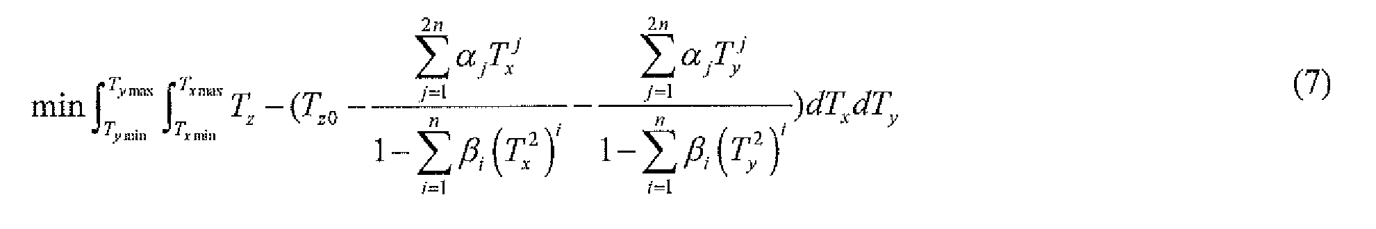
- step 506 a least square optimization method is applied to equation (6), which forms equation (7) and is solved for ⁇ 3 ⁇ 4 and ⁇ to ultimately approximate the TTI coefficients.
- a least square optimization method such as, for example, the well-known Bonded Variable Least Square optimization method may be used.
- a second order Pade approximation may be used to approximate the TTI coefficients.
- the maximum propagation angle is up to 50°.
- the upper limit of T x and T y for least square optimization is less than +0.85 and the lower limit of T x and T y is greater than - 0.85.
- the maximum propagation angle is up to 70°.
- the upper limit of T x and T y for least square optimization is less than +0.90 and the lower limit of T tribe and T y is greater than -0.90.
- the TTI coefficients (a i , b i , c i ) from equation (8) may be saved in respective tables before applying the hybrid TTI-WEM.
- hybrid TTI-RTM and conventional two-way TTI-RTM are applied to offshore data for a comparison of their resulting images.
- a phase shift algorithm was applied according to step 107 in FIG. 1 from a water surface to a subsurface where the water meets the earth.
- the hybrid ⁇ -WEM was applied according to step 107 in FIG. 1 from the subsurface to a migration depth of 2 km.
- the hybrid TTI-WEM was applied from 2 km to the extent of the velocity model at 16 km according to step 111 in FIG. 1.
- An image of the velocity model is illustrated in FIG. 2A.
- the anisotropic parameters for the velocity model in FIG. 2A are illustrated in FIGS.2 ⁇ ( ⁇ ), 2C(6) and 2D(9).
- FIG. 3C the application of the hybrid TTI-RTM as a result of the method 100 in FIG. 1 produces a much cleaner and clearer image (FIG.3C) than the images produced by conventional techniques in isotropic media (FIG. 3A) and conventional techniques in VTI media (FIG. 3B).
- the image in FIG. 3C is much cleaner and clearer than the image in FIG. 3D at the water layer, which was produced by a conventional two-way RTM in TTI media.
- the image ghost within circle 302d and circle 304d in FIG. 3D is not as evident within circle 302c and circle 304c in FIG. 3C.
- FIG. 3C the example illustrated by FIG.
- hybrid TTI-RTM saves 20% computational time than conventional two-way TTI-RTM when the migration depth is set at 2 km out of a total 16 km. If the migration depth is set deeper, more computational time may be saved.
- table 2 the relative computation time for hybrid TTI-RTM and two-way conventional TTI-RTM in isotropic, VTI and TTI media is illustrated for this example.
- the application of the hybrid TTI-RTM is tested on 2007 TTI data from BP.
- the image in FIG. 4A illustrates the results of conventional two-way TTI-RTM.
- the image in FIG. 4B illustrates the hybrid TTI-RTM as a result of the method 100 in FIG. 1.
- the conventional two-way TTI-RTM image in FIG. 4A accurately illustrates a salt boundary, noise appears on the top of the image and an image ghost appears within the circle 402a.
- hybrid TTI-RTM By applying hybrid TTI-RTM, tl e noise at the top of the image in FIG. 4B weakens and the image ghost within the circle 402b beside a salt boundary is significantly reduced.
- Hybrid TTI-RTM thus, will handle rugged topography and complex near surface layers by wave equation datuming.
- Conventional two-way TTI-RTM cannot handle topography or must apply vertical static shift to the pre-stack shot gather.
- Wave equation datuming is therefore, more accurate than applying a vertical static shift, especially for areas where the velocity contrast between the near surface and the substratum is not large.
- Hybrid TTI- WEM will also generate better results than applying a vertical static shift.
- the present invention may be implemented through a computer-executable program of instructions, such as program modules, generally referred to as software applications or application programs executed by a computer.
- the software may include, for example, routines, programs, objects, components, and data structures that perform particular tasks or implement particular abstract data types.
- the software forms an interface to allow a computer to react according to a source of input.
- SeisSpaceTM which is a commercial software application marketed by Landmark Graphics Corporation, may be used as an interface application to implement the present invention.
- the software may also cooperate with other code segments to initiate a variety of tasks in response to data received in conjunction with the source of the received data.
- the software may be stored and/or carried on any variety of memory media such as CD-ROM, magnetic disk, bubble memory and semiconductor memory (e.g., various types of RAM or ROM). Furthermore, the software and its results may be transmitted over a variety of carrier media such as optical fiber, metallic wire, free space and/or through any of a variety of networks such as the Internet.
- memory media such as CD-ROM, magnetic disk, bubble memory and semiconductor memory (e.g., various types of RAM or ROM).
- the software and its results may be transmitted over a variety of carrier media such as optical fiber, metallic wire, free space and/or through any of a variety of networks such as the Internet.
- the invention may be practiced with a variety of computer-system configurations, including hand-held devices, multiprocessor systems, microprocessor-based or programmable-consumer electronics, minicomputers, mainframe computers, and the like. Any number of computer-systems and computer networks are acceptable for use with the present invention.
- the invention may be practiced in distributed-computing environments where tasks are performed by remote- processing devices that are linked through a communications network.
- program modules may be located in both local and remote computer- storage media including memory storage devices.
- the present invention may therefore, be implemented in connection with various hardware, software or a combination thereof, in a computer system or other processing system.
- FIG. 6 a block diagram of a system for implementing the present invention on a computer is illustrated.
- the system includes a computing unit, sometimes referred to as a computing system, which contains memory, application programs, a client interface, a video interface and a processing unit that includes a graphics processor or graphics card.
- the computing unit is only one example of a suitable computing environment and is not intended to suggest any limitation as to the scope of use or functionality of the invention.
- the memory primarily stores the application programs, which may also be described as program modules containing computer-executable instructions, executed by the computing unit for implementing the present invention described herein and illustrated in FIGS. 1-5.
- the memory therefore, includes a hybrid TTI-WEM module and a hybrid TTI-RTM module, which enable the method illustrated and described in reference to FIG. 1. and integrates functionality from the remaining application programs illustrated in FIG. 6.
- the hybrid TTI- WTM module therefore, may be used to implement steps 104-110 in FIG. 1 and the hybrid TTI- RTM module may be used to implement steps 111-113 in FIG. 1.
- the TTI-WEM module and the TTI-RTM module may be combined into a single module to implement steps 104-113 in FIG. 1.
- the memory also includes SeisSpace,TM which may be used as an interface application to supply input data to the hybrid TTI-WEM module and the hybrid TTI-RTM module and/or display the data results from the hybrid TTI-WEM module and the hybrid TTI- RTM module.
- SeisSpaceTM may be used to implement steps 101-102b and 114-115 in FIG. 1.
- SeisSpaceTM may be used as an interface application, other interface applications may be used, instead, or each hybrid TTI-WEM module and hybrid TTI-RTM module may be used as a stand-alone application.
- the computing unit typically includes a variety of computer readable media.
- computer readable media may comprise computer storage media and communication media.
- the computing system memory may include computer storage media in the form of volatile and/or nonvolatile memory such as a read only memory (ROM) and random access memory (RAM).
- ROM read only memory
- RAM random access memory
- a basic input/output system (BIOS) containing the basic routines that help to transfer information between elements within the computing unit, such as during start-up, is typically stored in ROM.
- the RAM typically contains data and/or program modules that are immediately accessible to, and/or presently being operated on, the processing unit.
- the computing unit includes an operating system, application programs, other program modules, and program data.
- the components shown in the memory may also be included in other removable/nonremovable, volatile/nonvolatile computer storage media or they may be implemented in the computing unit through an application program interface ("API") or cloud computing, which may reside on a separate computing unit connected through a computer system or network.
- API application program interface
- a hard disk drive may read from or write to nonremovable, nonvolatile magnetic media
- a magnetic disk drive may read from or write to a removable, nonvolatile magnetic disk
- an optical disk drive may read from or write to a removable, nonvolatile optical disk such as a CD ROM or other optical media.
- removable/non-removable, volatile/nonvolatile computer storage media that can be used in the exemplary operating environment may include, but are not limited to, magnetic tape cassettes, flash memory cards, digital versatile disks, digital video tape, solid state RAM, solid state ROM, and the like.
- the drives and their associated computer storage media discussed above provide storage of computer readable instructions, data structures, program modules and other data for the computing unit
- a client may enter commands and information into the computing unit through the client interface, which may be input devices such as a keyboard and pointing device, commonly referred to as a mouse, trackball or touch pad. Input devices may include a microphone, joystick, satellite dish, scanner, or the like. These and other input devices are often connected to the processing unit through the client interface that is coupled to a system bus, but may be connected by other interface and bus structures, such as a parallel port or a universal serial bus (USB).
- USB universal serial bus
- a monitor or other type of display device may be connected to the system bus via an interface, such as a video interface.
- a graphical user interface may also be used with the video interface to receive instructions from the client interface and transmit instructions to the processing unit.
- computers may also include other peripheral output devices such as speakers and printer, which may be connected through an output peripheral interface.
Abstract
Description


Claims
Priority Applications (6)
| Application Number | Priority Date | Filing Date | Title |
|---|---|---|---|
| PCT/US2012/051387 WO2014028030A1 (en) | 2012-08-17 | 2012-08-17 | Systems and methods for imaging seismic data |
| RU2015104566/28A RU2596182C1 (en) | 2012-08-17 | 2012-08-17 | System and method for displaying seismic data |
| US14/422,096 US9536143B2 (en) | 2012-08-17 | 2012-08-17 | Systems and methods for imaging seismic data |
| AU2012387658A AU2012387658B2 (en) | 2012-08-17 | 2012-08-17 | Systems and methods for imaging seismic data |
| CA2881807A CA2881807C (en) | 2012-08-17 | 2012-08-17 | Systems and methods for imaging seismic data |
| EP12886507.8A EP2885656B1 (en) | 2012-08-17 | 2012-08-17 | Methods for imaging seismic data |
Applications Claiming Priority (1)
| Application Number | Priority Date | Filing Date | Title |
|---|---|---|---|
| PCT/US2012/051387 WO2014028030A1 (en) | 2012-08-17 | 2012-08-17 | Systems and methods for imaging seismic data |
Publications (1)
| Publication Number | Publication Date |
|---|---|
| WO2014028030A1 true WO2014028030A1 (en) | 2014-02-20 |
Family
ID=50685678
Family Applications (1)
| Application Number | Title | Priority Date | Filing Date |
|---|---|---|---|
| PCT/US2012/051387 WO2014028030A1 (en) | 2012-08-17 | 2012-08-17 | Systems and methods for imaging seismic data |
Country Status (6)
| Country | Link |
|---|---|
| US (1) | US9536143B2 (en) |
| EP (1) | EP2885656B1 (en) |
| AU (1) | AU2012387658B2 (en) |
| CA (1) | CA2881807C (en) |
| RU (1) | RU2596182C1 (en) |
| WO (1) | WO2014028030A1 (en) |
Cited By (6)
| Publication number | Priority date | Publication date | Assignee | Title |
|---|---|---|---|---|
| CN104635267A (en) * | 2015-02-10 | 2015-05-20 | 中国海洋大学 | Seismic wave sublevel reverse time migration weighting stack imaging method |
| WO2016008100A1 (en) * | 2014-07-15 | 2016-01-21 | 杨顺伟 | Three-dimensional seismic anisotropic medium reverse time migration imaging method and device |
| CN105652321A (en) * | 2015-12-30 | 2016-06-08 | 中国石油大学(华东) | Visco-acoustic anisotropic least square inverse time migration imaging method |
| CN107179549A (en) * | 2017-07-11 | 2017-09-19 | 中海石油(中国)有限公司 | A kind of acoustic wave equation in time domain Explicit finite difference seismic response analogy method |
| CN107193043A (en) * | 2017-05-15 | 2017-09-22 | 中国石油大学(华东) | A kind of subsurface structure imaging method of relief surface |
| CN108646294A (en) * | 2018-06-29 | 2018-10-12 | 中海石油(中国)有限公司 | Deep water turbidite sandstone reservoir high-precision inversion method under a kind of complicated fault system |
Families Citing this family (17)
| Publication number | Priority date | Publication date | Assignee | Title |
|---|---|---|---|---|
| CA2797434C (en) * | 2010-05-12 | 2017-09-19 | Shell Internationale Research Maatschappij B.V. | Seismic p-wave modelling in an inhomogeneous transversely isotropic medium with a tilted symmetry axis |
| US10302741B2 (en) * | 2015-04-02 | 2019-05-28 | Texas Instruments Incorporated | Method and apparatus for live-object detection |
| CN105425287B (en) * | 2015-11-09 | 2017-10-27 | 中国地质大学(北京) | The prestack separation method of seismic wave |
| US10535168B2 (en) * | 2016-03-02 | 2020-01-14 | Schlumberger Technology Corporation | Image enhancement using seismic partition images |
| CN106199717B (en) * | 2016-07-08 | 2018-07-13 | 中国石油天然气集团公司 | Azimuthal anisotropy Residual moveout correction method and device |
| WO2018118733A2 (en) * | 2016-12-19 | 2018-06-28 | Schlumberger Technology Corporation | Cloud framework system |
| US10295685B2 (en) | 2017-04-06 | 2019-05-21 | Saudi Arabian Oil Company | Generating common image gather using wave-field separation |
| US11016212B2 (en) | 2017-04-11 | 2021-05-25 | Saudi Arabian Oil Company | Compressing seismic wavefields in three-dimensional reverse time migration |
| US10557954B2 (en) * | 2017-06-12 | 2020-02-11 | Saudi Arabian Oil Company | Modeling angle domain common image gathers from reverse time migration |
| US10788597B2 (en) | 2017-12-11 | 2020-09-29 | Saudi Arabian Oil Company | Generating a reflectivity model of subsurface structures |
| US11275190B2 (en) | 2018-05-16 | 2022-03-15 | Saudi Arabian Oil Company | Generating diffraction images based on wave equations |
| US11681043B2 (en) * | 2019-09-03 | 2023-06-20 | Saudi Arabian Oil Company | Diffraction imaging using pseudo dip-angle gather |
| US11313988B2 (en) | 2019-12-13 | 2022-04-26 | Saudi Arabian Oil Company | Identifying geologic features in a subterranean formation using seismic diffraction imaging |
| US11402529B2 (en) | 2020-01-09 | 2022-08-02 | Saudi Arabian Oil Company | Identifying geologic features in a subterranean formation using seismic diffraction and refraction imaging |
| US11467303B2 (en) | 2020-03-09 | 2022-10-11 | Saudi Arabian Oil Company | Identifying geologic features in a subterranean formation using a post-stack seismic diffraction imaging condition |
| US11320557B2 (en) | 2020-03-30 | 2022-05-03 | Saudi Arabian Oil Company | Post-stack time domain image with broadened spectrum |
| US11656378B2 (en) | 2020-06-08 | 2023-05-23 | Saudi Arabian Oil Company | Seismic imaging by visco-acoustic reverse time migration |
Citations (9)
| Publication number | Priority date | Publication date | Assignee | Title |
|---|---|---|---|---|
| US4809235A (en) * | 1987-09-28 | 1989-02-28 | Western Atlas International, Inc. | Method for removing doppler phase dispersion from seismic data |
| US5392213A (en) * | 1992-10-23 | 1995-02-21 | Exxon Production Research Company | Filter for removal of coherent noise from seismic data |
| US5933789A (en) * | 1996-11-12 | 1999-08-03 | Atlantic Richfield Company | Method and system for applying dispersive normal moveout corrections to seismic survey signals |
| US20030195705A1 (en) * | 2002-04-10 | 2003-10-16 | Scott Leaney | Method and apparatus for anisotropic vector plane wave decomposition for 3D vertical seismic profile data |
| US20040196738A1 (en) * | 2003-04-07 | 2004-10-07 | Hillel Tal-Ezer | Wave migration by a krylov space expansion of the square root exponent operator, for use in seismic imaging |
| US20080319726A1 (en) * | 2007-06-19 | 2008-12-25 | Schlumberger Technology Corporation | System and method for performing oilfield simulation operations |
| US20090213693A1 (en) * | 2008-01-18 | 2009-08-27 | Xiang Du | Using a wave propagator for transversely isotropic media |
| WO2011053327A1 (en) * | 2009-11-02 | 2011-05-05 | Landmark Graphics Corporation | Seismic imaging systems and methods employing a 3d reverse time migration with tilted transverse isotropy |
| US8116168B1 (en) * | 2008-06-18 | 2012-02-14 | Halliburton Energy Services, Inc. | Hybrid one-way and full-way wave equation migration |
Family Cites Families (19)
| Publication number | Priority date | Publication date | Assignee | Title |
|---|---|---|---|---|
| US5999488A (en) | 1998-04-27 | 1999-12-07 | Phillips Petroleum Company | Method and apparatus for migration by finite differences |
| DE19841262C2 (en) | 1998-09-09 | 2000-12-28 | Ibs Integrierte Business Syste | Electronic circuit for recording geographic position data on the sound channel of a camcorder |
| US6021094A (en) | 1998-12-03 | 2000-02-01 | Sandia Corporation | Method of migrating seismic records |
| US6687659B1 (en) | 2000-03-24 | 2004-02-03 | Conocophillips Company | Method and apparatus for absorbing boundary conditions in numerical finite-difference acoustic applications |
| WO2001073476A1 (en) | 2000-03-27 | 2001-10-04 | Ortoleva Peter J | Method for simulation of enhanced fracture detection in sedimentary basins |
| AU2002239619A1 (en) | 2000-12-08 | 2002-06-18 | Peter J. Ortoleva | Methods for modeling multi-dimensional domains using information theory to resolve gaps in data and in theories |
| US6519532B2 (en) | 2001-01-31 | 2003-02-11 | Phillips Petroleum Company | Method and apparatus for 3D depth migration |
| US20070162249A1 (en) | 2006-01-06 | 2007-07-12 | Min Lou | Traveltime calculation in three dimensional transversely isotropic (3D TTI) media by the fast marching method |
| US7400553B1 (en) | 2006-11-30 | 2008-07-15 | Shengwen Jin | One-return wave equation migration |
| WO2008087505A2 (en) | 2007-01-20 | 2008-07-24 | Spectraseis Ag | Time reverse reservoir localization |
| EP2308025A4 (en) | 2008-07-30 | 2016-11-16 | Chevron Usa Inc | Method for propagating pseudo acoustic quasi-p waves in anisotropic media |
| EP2184620B1 (en) * | 2008-08-26 | 2011-10-26 | PGS Geophysical AS | Fourier finite-difference migration for three dimensional tilted transverse isotropic media |
| US20100054082A1 (en) | 2008-08-29 | 2010-03-04 | Acceleware Corp. | Reverse-time depth migration with reduced memory requirements |
| US8296069B2 (en) | 2008-10-06 | 2012-10-23 | Bp Corporation North America Inc. | Pseudo-analytical method for the solution of wave equations |
| US20100118651A1 (en) | 2008-11-10 | 2010-05-13 | Chevron U.S.A. Inc. | Method for generation of images related to a subsurface region of interest |
| US20100135115A1 (en) * | 2008-12-03 | 2010-06-03 | Chevron U.S.A. Inc. | Multiple anisotropic parameter inversion for a tti earth model |
| US20110286305A1 (en) | 2009-01-20 | 2011-11-24 | Spectraseis Ag | Time reverse imaging operators for source location |
| CA2750260A1 (en) | 2009-01-20 | 2010-07-29 | Spectraseis Ag | Image domain signal to noise estimate |
| CA2797434C (en) * | 2010-05-12 | 2017-09-19 | Shell Internationale Research Maatschappij B.V. | Seismic p-wave modelling in an inhomogeneous transversely isotropic medium with a tilted symmetry axis |
-
2012
- 2012-08-17 RU RU2015104566/28A patent/RU2596182C1/en not_active IP Right Cessation
- 2012-08-17 EP EP12886507.8A patent/EP2885656B1/en not_active Not-in-force
- 2012-08-17 CA CA2881807A patent/CA2881807C/en not_active Expired - Fee Related
- 2012-08-17 US US14/422,096 patent/US9536143B2/en active Active
- 2012-08-17 AU AU2012387658A patent/AU2012387658B2/en not_active Ceased
- 2012-08-17 WO PCT/US2012/051387 patent/WO2014028030A1/en active Application Filing
Patent Citations (9)
| Publication number | Priority date | Publication date | Assignee | Title |
|---|---|---|---|---|
| US4809235A (en) * | 1987-09-28 | 1989-02-28 | Western Atlas International, Inc. | Method for removing doppler phase dispersion from seismic data |
| US5392213A (en) * | 1992-10-23 | 1995-02-21 | Exxon Production Research Company | Filter for removal of coherent noise from seismic data |
| US5933789A (en) * | 1996-11-12 | 1999-08-03 | Atlantic Richfield Company | Method and system for applying dispersive normal moveout corrections to seismic survey signals |
| US20030195705A1 (en) * | 2002-04-10 | 2003-10-16 | Scott Leaney | Method and apparatus for anisotropic vector plane wave decomposition for 3D vertical seismic profile data |
| US20040196738A1 (en) * | 2003-04-07 | 2004-10-07 | Hillel Tal-Ezer | Wave migration by a krylov space expansion of the square root exponent operator, for use in seismic imaging |
| US20080319726A1 (en) * | 2007-06-19 | 2008-12-25 | Schlumberger Technology Corporation | System and method for performing oilfield simulation operations |
| US20090213693A1 (en) * | 2008-01-18 | 2009-08-27 | Xiang Du | Using a wave propagator for transversely isotropic media |
| US8116168B1 (en) * | 2008-06-18 | 2012-02-14 | Halliburton Energy Services, Inc. | Hybrid one-way and full-way wave equation migration |
| WO2011053327A1 (en) * | 2009-11-02 | 2011-05-05 | Landmark Graphics Corporation | Seismic imaging systems and methods employing a 3d reverse time migration with tilted transverse isotropy |
Non-Patent Citations (1)
| Title |
|---|
| See also references of EP2885656A4 * |
Cited By (10)
| Publication number | Priority date | Publication date | Assignee | Title |
|---|---|---|---|---|
| WO2016008100A1 (en) * | 2014-07-15 | 2016-01-21 | 杨顺伟 | Three-dimensional seismic anisotropic medium reverse time migration imaging method and device |
| CN104635267A (en) * | 2015-02-10 | 2015-05-20 | 中国海洋大学 | Seismic wave sublevel reverse time migration weighting stack imaging method |
| CN104635267B (en) * | 2015-02-10 | 2015-08-19 | 中国海洋大学 | A kind of seismic event sublevel reverse-time migration weighted stacking formation method |
| CN105652321A (en) * | 2015-12-30 | 2016-06-08 | 中国石油大学(华东) | Visco-acoustic anisotropic least square inverse time migration imaging method |
| CN105652321B (en) * | 2015-12-30 | 2016-10-12 | 中国石油大学(华东) | A kind of viscous acoustic anisotropy least square reverse-time migration formation method |
| CN107193043A (en) * | 2017-05-15 | 2017-09-22 | 中国石油大学(华东) | A kind of subsurface structure imaging method of relief surface |
| CN107193043B (en) * | 2017-05-15 | 2019-03-29 | 中国石油大学(华东) | A kind of subsurface structure imaging method of relief surface |
| CN107179549A (en) * | 2017-07-11 | 2017-09-19 | 中海石油(中国)有限公司 | A kind of acoustic wave equation in time domain Explicit finite difference seismic response analogy method |
| CN108646294A (en) * | 2018-06-29 | 2018-10-12 | 中海石油(中国)有限公司 | Deep water turbidite sandstone reservoir high-precision inversion method under a kind of complicated fault system |
| CN108646294B (en) * | 2018-06-29 | 2019-09-06 | 中海石油(中国)有限公司 | Deep water turbidite sandstone reservoir high-precision inversion method under a kind of complicated fault system |
Also Published As
| Publication number | Publication date |
|---|---|
| US9536143B2 (en) | 2017-01-03 |
| US20150235081A1 (en) | 2015-08-20 |
| EP2885656A1 (en) | 2015-06-24 |
| CA2881807A1 (en) | 2014-02-20 |
| RU2596182C1 (en) | 2016-08-27 |
| EP2885656B1 (en) | 2018-09-26 |
| EP2885656A4 (en) | 2016-04-06 |
| CA2881807C (en) | 2017-10-17 |
| AU2012387658A1 (en) | 2015-02-26 |
| AU2012387658B2 (en) | 2016-06-23 |
Similar Documents
| Publication | Publication Date | Title |
|---|---|---|
| AU2012387658B2 (en) | Systems and methods for imaging seismic data | |
| Ren et al. | Least-squares reverse time migration in elastic media | |
| Zhang et al. | Delayed-shot 3D depth migration | |
| Duan et al. | Scalar imaging condition for elastic reverse time migration | |
| Zhang et al. | Amplitude-preserving reverse time migration: From reflectivity to velocity and impedance inversion | |
| US10620331B2 (en) | Reverse time migration in anisotropic media with stable attenuation compensation | |
| US7355923B2 (en) | Seismic analysis using post-imaging seismic anisotropy corrections | |
| US9829592B2 (en) | Seismic imaging with visco-acoustic reverse-time migration using pseudo-analytical method | |
| Oh et al. | 3D elastic full-waveform inversion using P-wave excitation amplitude: Application to ocean bottom cable field data | |
| JP7145866B2 (en) | Geophysical imaging using directional wavefield imaging | |
| US9465125B2 (en) | Seismic data processing including compensating for source and receiver ghost effects in reverse time migration | |
| Wang et al. | Reverse time migration of multiples: Reducing migration artifacts using the wavefield decomposition imaging condition | |
| MX2007003373A (en) | Method for depth migrating seismic data using pre-stack time migration, demigration, and post-stack depth migration. | |
| US20170184748A1 (en) | A method and a computing system for seismic imaging a geological formation | |
| US10996361B2 (en) | Adaptive receiver deghosting for seismic streamer | |
| Gong et al. | Polarized wavefield magnitudes with optical flow for elastic angle-domain common-image gathers | |
| US20180059276A1 (en) | System and method for focusing seismic images | |
| Yan et al. | The new angle-domain imaging condition for elastic RTM | |
| Sun et al. | Compensating for source and receiver ghost effects in full waveform inversion and reverse time migration for marine streamer data | |
| Lin et al. | Improving the image quality of high-angle interfaces and subsalt sediments using high-order scattered seismic waves | |
| Jing et al. | Benefits and applications of elastic reverse time migration in salt-related imaging | |
| Gerritsen et al. | Wave-equation-based residual moveout inversion in the subsurface angle domain for sub salt velocity model building | |
| Rusmanugroho et al. | Pre-Stack Depth Migration of High Resolution Distributed Acoustic Sensing VSP | |
| Grech et al. | Integrating borehole information and surface seismic for velocity anisotropy analysis and depth imaging | |
| Du | Prestack Depth Migration Methods for Isotopic and Polar Anisotropic Media |
Legal Events
| Date | Code | Title | Description |
|---|---|---|---|
| DPE2 | Request for preliminary examination filed before expiration of 19th month from priority date (pct application filed from 20040101) | ||
| 121 | Ep: the epo has been informed by wipo that ep was designated in this application |
Ref document number: 12886507 Country of ref document: EP Kind code of ref document: A1 |
|
| WWE | Wipo information: entry into national phase |
Ref document number: 2012886507 Country of ref document: EP |
|
| ENP | Entry into the national phase |
Ref document number: 2881807 Country of ref document: CA |
|
| NENP | Non-entry into the national phase |
Ref country code: DE |
|
| WWE | Wipo information: entry into national phase |
Ref document number: 14422096 Country of ref document: US |
|
| ENP | Entry into the national phase |
Ref document number: 2012387658 Country of ref document: AU Date of ref document: 20120817 Kind code of ref document: A |
|
| ENP | Entry into the national phase |
Ref document number: 2015104566 Country of ref document: RU Kind code of ref document: A |