WO2014025026A1 - Manufacturing method for surface-enhanced raman scattering element - Google Patents
Manufacturing method for surface-enhanced raman scattering element Download PDFInfo
- Publication number
- WO2014025026A1 WO2014025026A1 PCT/JP2013/071695 JP2013071695W WO2014025026A1 WO 2014025026 A1 WO2014025026 A1 WO 2014025026A1 JP 2013071695 W JP2013071695 W JP 2013071695W WO 2014025026 A1 WO2014025026 A1 WO 2014025026A1
- Authority
- WO
- WIPO (PCT)
- Prior art keywords
- wafer
- layer
- raman scattering
- substrate
- mold
- Prior art date
Links
- 238000004416 surface enhanced Raman spectroscopy Methods 0.000 title claims abstract description 131
- 238000004519 manufacturing process Methods 0.000 title claims abstract description 92
- 239000000758 substrate Substances 0.000 claims abstract description 85
- 239000004020 conductor Substances 0.000 claims abstract description 74
- 238000000034 method Methods 0.000 claims abstract description 63
- 230000003287 optical effect Effects 0.000 claims abstract description 29
- 238000000465 moulding Methods 0.000 claims description 86
- 238000005520 cutting process Methods 0.000 claims description 72
- 238000001069 Raman spectroscopy Methods 0.000 claims description 13
- 230000001678 irradiating effect Effects 0.000 claims description 4
- 239000010410 layer Substances 0.000 description 187
- 235000012431 wafers Nutrition 0.000 description 115
- 239000000463 material Substances 0.000 description 13
- 229920005989 resin Polymers 0.000 description 13
- 239000011347 resin Substances 0.000 description 13
- 229910052751 metal Inorganic materials 0.000 description 9
- 239000002184 metal Substances 0.000 description 9
- LFQSCWFLJHTTHZ-UHFFFAOYSA-N Ethanol Chemical compound CCO LFQSCWFLJHTTHZ-UHFFFAOYSA-N 0.000 description 6
- 230000015572 biosynthetic process Effects 0.000 description 6
- 230000001681 protective effect Effects 0.000 description 6
- 238000007740 vapor deposition Methods 0.000 description 6
- 230000000694 effects Effects 0.000 description 5
- 238000012986 modification Methods 0.000 description 5
- 230000004048 modification Effects 0.000 description 5
- 239000011521 glass Substances 0.000 description 4
- 239000000843 powder Substances 0.000 description 4
- 239000000126 substance Substances 0.000 description 4
- XLYOFNOQVPJJNP-UHFFFAOYSA-N water Substances O XLYOFNOQVPJJNP-UHFFFAOYSA-N 0.000 description 4
- YCKRFDGAMUMZLT-UHFFFAOYSA-N Fluorine atom Chemical compound [F] YCKRFDGAMUMZLT-UHFFFAOYSA-N 0.000 description 3
- 239000003795 chemical substances by application Substances 0.000 description 3
- 239000006059 cover glass Substances 0.000 description 3
- 230000002950 deficient Effects 0.000 description 3
- 239000011737 fluorine Substances 0.000 description 3
- 229910052731 fluorine Inorganic materials 0.000 description 3
- 229910052737 gold Inorganic materials 0.000 description 3
- 229920000139 polyethylene terephthalate Polymers 0.000 description 3
- 239000005020 polyethylene terephthalate Substances 0.000 description 3
- 238000007493 shaping process Methods 0.000 description 3
- 229910052710 silicon Inorganic materials 0.000 description 3
- 239000010703 silicon Substances 0.000 description 3
- 229910052709 silver Inorganic materials 0.000 description 3
- PXHVJJICTQNCMI-UHFFFAOYSA-N Nickel Chemical compound [Ni] PXHVJJICTQNCMI-UHFFFAOYSA-N 0.000 description 2
- 238000011109 contamination Methods 0.000 description 2
- 230000005284 excitation Effects 0.000 description 2
- 238000010438 heat treatment Methods 0.000 description 2
- 239000011159 matrix material Substances 0.000 description 2
- 238000002844 melting Methods 0.000 description 2
- 239000004417 polycarbonate Substances 0.000 description 2
- 229920000515 polycarbonate Polymers 0.000 description 2
- 229920001296 polysiloxane Polymers 0.000 description 2
- 238000004611 spectroscopical analysis Methods 0.000 description 2
- 238000004381 surface treatment Methods 0.000 description 2
- 238000002834 transmittance Methods 0.000 description 2
- 239000004925 Acrylic resin Substances 0.000 description 1
- 229920000178 Acrylic resin Polymers 0.000 description 1
- 239000004593 Epoxy Substances 0.000 description 1
- JOYRKODLDBILNP-UHFFFAOYSA-N Ethyl urethane Chemical compound CCOC(N)=O JOYRKODLDBILNP-UHFFFAOYSA-N 0.000 description 1
- 229910001111 Fine metal Inorganic materials 0.000 description 1
- 239000004642 Polyimide Substances 0.000 description 1
- NIXOWILDQLNWCW-UHFFFAOYSA-N acrylic acid group Chemical group C(C=C)(=O)O NIXOWILDQLNWCW-UHFFFAOYSA-N 0.000 description 1
- 229910052782 aluminium Inorganic materials 0.000 description 1
- 238000003763 carbonization Methods 0.000 description 1
- 239000000919 ceramic Substances 0.000 description 1
- 229910052804 chromium Inorganic materials 0.000 description 1
- 229910052802 copper Inorganic materials 0.000 description 1
- 230000007423 decrease Effects 0.000 description 1
- 238000000151 deposition Methods 0.000 description 1
- 238000010586 diagram Methods 0.000 description 1
- 238000009826 distribution Methods 0.000 description 1
- 238000010894 electron beam technology Methods 0.000 description 1
- 239000003822 epoxy resin Substances 0.000 description 1
- 230000005496 eutectics Effects 0.000 description 1
- 230000004927 fusion Effects 0.000 description 1
- 239000007789 gas Substances 0.000 description 1
- 238000005259 measurement Methods 0.000 description 1
- 230000008018 melting Effects 0.000 description 1
- 229910052759 nickel Inorganic materials 0.000 description 1
- 239000003921 oil Substances 0.000 description 1
- 238000004806 packaging method and process Methods 0.000 description 1
- 230000000737 periodic effect Effects 0.000 description 1
- 229910052697 platinum Inorganic materials 0.000 description 1
- 229920000647 polyepoxide Polymers 0.000 description 1
- -1 polyethylene terephthalate Polymers 0.000 description 1
- 229920001721 polyimide Polymers 0.000 description 1
- 238000003825 pressing Methods 0.000 description 1
- 230000000644 propagated effect Effects 0.000 description 1
- 239000010453 quartz Substances 0.000 description 1
- VYPSYNLAJGMNEJ-UHFFFAOYSA-N silicon dioxide Inorganic materials O=[Si]=O VYPSYNLAJGMNEJ-UHFFFAOYSA-N 0.000 description 1
- 229920002050 silicone resin Polymers 0.000 description 1
- 238000009751 slip forming Methods 0.000 description 1
- 229910000679 solder Inorganic materials 0.000 description 1
- 238000004544 sputter deposition Methods 0.000 description 1
- 239000002344 surface layer Substances 0.000 description 1
- 229920002803 thermoplastic polyurethane Polymers 0.000 description 1
Images


Classifications
-
- G—PHYSICS
- G01—MEASURING; TESTING
- G01J—MEASUREMENT OF INTENSITY, VELOCITY, SPECTRAL CONTENT, POLARISATION, PHASE OR PULSE CHARACTERISTICS OF INFRARED, VISIBLE OR ULTRAVIOLET LIGHT; COLORIMETRY; RADIATION PYROMETRY
- G01J3/00—Spectrometry; Spectrophotometry; Monochromators; Measuring colours
- G01J3/02—Details
- G01J3/0205—Optical elements not provided otherwise, e.g. optical manifolds, diffusers, windows
-
- G—PHYSICS
- G01—MEASURING; TESTING
- G01J—MEASUREMENT OF INTENSITY, VELOCITY, SPECTRAL CONTENT, POLARISATION, PHASE OR PULSE CHARACTERISTICS OF INFRARED, VISIBLE OR ULTRAVIOLET LIGHT; COLORIMETRY; RADIATION PYROMETRY
- G01J3/00—Spectrometry; Spectrophotometry; Monochromators; Measuring colours
- G01J3/28—Investigating the spectrum
- G01J3/44—Raman spectrometry; Scattering spectrometry ; Fluorescence spectrometry
- G01J3/4412—Scattering spectrometry
-
- G—PHYSICS
- G01—MEASURING; TESTING
- G01N—INVESTIGATING OR ANALYSING MATERIALS BY DETERMINING THEIR CHEMICAL OR PHYSICAL PROPERTIES
- G01N21/00—Investigating or analysing materials by the use of optical means, i.e. using sub-millimetre waves, infrared, visible or ultraviolet light
- G01N21/62—Systems in which the material investigated is excited whereby it emits light or causes a change in wavelength of the incident light
- G01N21/63—Systems in which the material investigated is excited whereby it emits light or causes a change in wavelength of the incident light optically excited
- G01N21/65—Raman scattering
- G01N21/658—Raman scattering enhancement Raman, e.g. surface plasmons
-
- Y—GENERAL TAGGING OF NEW TECHNOLOGICAL DEVELOPMENTS; GENERAL TAGGING OF CROSS-SECTIONAL TECHNOLOGIES SPANNING OVER SEVERAL SECTIONS OF THE IPC; TECHNICAL SUBJECTS COVERED BY FORMER USPC CROSS-REFERENCE ART COLLECTIONS [XRACs] AND DIGESTS
- Y10—TECHNICAL SUBJECTS COVERED BY FORMER USPC
- Y10T—TECHNICAL SUBJECTS COVERED BY FORMER US CLASSIFICATION
- Y10T29/00—Metal working
- Y10T29/49—Method of mechanical manufacture
- Y10T29/49002—Electrical device making
- Y10T29/49117—Conductor or circuit manufacturing
- Y10T29/49124—On flat or curved insulated base, e.g., printed circuit, etc.
- Y10T29/49155—Manufacturing circuit on or in base
Definitions
- the present invention relates to a method for manufacturing a surface-enhanced Raman scattering element.
- a device including a minute metal structure that causes surface enhanced Raman scattering As a conventional surface-enhanced Raman scattering element, a device including a minute metal structure that causes surface enhanced Raman scattering (SERS) is known (see, for example, Patent Document 1 and Non-Patent Document 1).
- SERS surface enhanced Raman scattering
- a sample to be subjected to Raman spectroscopic analysis is brought into contact with a fine metal structure and the sample is irradiated with excitation light in this state, surface-enhanced Raman scattering occurs, For example, Raman scattered light enhanced to about 10 8 times is emitted.
- a plurality of minute pillars are formed on a substrate by vapor deposition, and a metal film is formed on the top of the pillar by vapor deposition.
- a method of forming a micro metal structure by forming is described.
- an object of the present invention is to provide a method for manufacturing a surface-enhanced Raman scattering element that can efficiently and stably manufacture a surface-enhanced Raman scattering element.
- a method of manufacturing a surface-enhanced Raman scattering element includes a substrate having a main surface, a molding layer formed on the main surface and including a fine structure portion, and formed on the fine structure portion.
- a surface-enhanced Raman scattering element manufacturing method comprising: a conductor layer that constitutes an optical functional unit that causes scattering; and a first method of forming a nanoimprint layer on a main surface of a wafer including a plurality of portions corresponding to a substrate
- a molding layer including the fine structure portion is provided for each portion corresponding to the substrate.
- the second step to be formed, the third step to form a conductor layer on the fine structure portion after the second step, and the wafer corresponding to the substrate are cut after the second step.
- a molding layer including a fine structure portion is formed for each portion corresponding to a substrate by transferring a mold pattern onto a nanoimprint layer on a wafer.
- a fine structure part can be formed efficiently and stably. Therefore, according to the method for manufacturing the surface-enhanced Raman scattering element, the surface-enhanced Raman scattering element can be manufactured efficiently and stably.
- the fourth step may be performed after the third step.
- a conductor layer can be formed in a lump for a plurality of microstructures on the wafer, a surface-enhanced Raman scattering element can be manufactured more efficiently.
- the mold may have flexibility.
- the mold can be easily released from the nanoimprint layer.
- the mold follows the distortion or the like of the wafer, so that the fine structure portion can be stably formed.
- the mold may have elasticity.
- the foreign substance or the like is likely to bite into the mold side. For this reason, the range of transfer failure can be suppressed.
- the mold pattern easily follows the nanoimprint layer, the fine structure can be stably formed.
- the mold follows the irregularities and the like of the wafer, so that the fine structure can be formed more stably.
- the mold may have a plurality of patterns, and in the second step, the plurality of patterns may be simultaneously transferred to the nanoimprint layer using the mold. .
- the plurality of patterns may be simultaneously transferred to the nanoimprint layer using the mold.
- a plurality of patterns are separated from each other in the mold, and in the second step, the plurality of microstructures are separated from each other using the mold.
- a plurality of patterns may be simultaneously transferred to the nanoimprint layer.
- the wafer can be easily cut as a guideline for cutting the wafer between adjacent fine structures.
- a plurality of patterns are continuous in the mold, and in the second step, the plurality of microstructures are continuously formed using the mold.
- a plurality of patterns may be simultaneously transferred to the nanoimprint layer.
- the molding layer and the conductor layer existing on the cutting line passing through the portion corresponding to the substrate are cut together with the wafer. Also good.
- the molding layer and the conductor layer can be integrally formed over the entire portion corresponding to the substrate, the surface-enhanced Raman scattering element can be manufactured more efficiently.
- the crack is propagated from the starting point of the cutting formed on the wafer along the planned cutting line, thereby existing on the planned cutting line.
- the forming layer and the conductor layer to be cut may be cut together with the wafer. In this case, since it is not necessary to form the starting point of cutting in the molding layer and the conductor layer, it is possible to prevent the fine structure portion and the optical function portion from being damaged.
- the molding layer includes a support portion that supports the fine structure portion on the main surface of the substrate, and an annular frame that surrounds the support portion on the main surface of the substrate.
- a frame existing on the planned cutting line is developed by causing a crack to propagate from the starting point of the cutting formed on the wafer along the planned cutting line passing through the portion corresponding to the substrate.
- the part and the conductor layer may be cut together with the wafer. In this case, an impact or the like due to the cutting can be suitably buffered in the frame portion, and thus it is possible to suppress damage to the fine structure portion and the optical function portion during the cutting.
- the laser beam is irradiated with a converging point inside the wafer. Then, a modified region may be formed inside the wafer.
- the laser beam irradiation except for the vicinity of the condensing point of the laser beam inside the wafer, it is hardly affected by the laser beam irradiation, so that it is possible to suppress damage to the fine structure portion and the optical function portion during the cutting. Further, the molded layer and the conductor layer on the planned cutting line can be accurately cut together with the wafer by utilizing the crack that has progressed from the modified region.
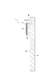
- FIG. 2 is a cross-sectional view taken along the line II-II in FIG. It is an expanded sectional view of the optical function part of FIG. It is a SEM photograph of the optical function part of FIG. It is a perspective view which shows the manufacturing process of the surface enhancement Raman scattering element of FIG. It is a perspective view which shows the manufacturing process of the surface enhancement Raman scattering element of FIG. It is sectional drawing which shows the process of cut
- FIG. 1 It is a perspective view which shows the manufacturing process of the surface enhancement Raman scattering element of other embodiment of this invention. It is an expanded sectional view which shows the modification of FIG. It is sectional drawing which shows the modification of the process of cut
- the SERS unit (surface enhanced Raman scattering unit) 1 includes a handling board 2 and a SERS element (surface enhanced Raman scattering element) 3 attached on the handling board 2.
- the handling substrate 2 is a rectangular plate-shaped slide glass, a resin substrate, a ceramic substrate, or the like.
- the SERS element 3 is arranged on the surface 2 a of the handling substrate 2 in a state of being offset from one end portion in the longitudinal direction of the handling substrate 2.
- the SERS element 3 includes a substrate 4 attached on the handling substrate 2, a molding layer 5 formed on the substrate 4, and a conductor layer 6 formed on the molding layer 5.
- the substrate 4 is formed in a rectangular plate shape with silicon or glass or the like, and has an outer shape of about several hundred ⁇ m ⁇ several hundred ⁇ m to several tens of mm ⁇ several tens of mm and a thickness of about 100 ⁇ m to 2 mm.
- the back surface 4b of the substrate 4 is formed on the surface 2a of the handling substrate 2 by direct bonding, bonding using a metal such as solder, eutectic bonding, fusion bonding by laser light irradiation, anodic bonding, or bonding using a resin. It is fixed.
- the molding layer 5 includes a fine structure portion 7, a support portion 8, and a frame portion 9.
- the fine structure portion 7 is a region having a periodic pattern, and is formed on the surface layer opposite to the substrate 4 in the central portion of the molding layer 5.
- a plurality of cylindrical pillars 71 having a diameter and height of about several nm to several ⁇ m are provided in the fine structure portion 7 along the surface (main surface) 4a of the substrate 4 about several tens nm to several hundreds nm. Are periodically arranged at a pitch of.
- the fine structure portion 7 When viewed from the thickness direction of the substrate 4, the fine structure portion 7 has a rectangular outer shape of about several hundred ⁇ m ⁇ several hundred ⁇ m to several tens mm ⁇ several tens mm.
- the support portion 8 is a rectangular region that supports the fine structure portion 7, and is formed on the surface 4 a of the substrate 4.
- the frame portion 9 is a rectangular annular region surrounding the fine structure portion 7 and the support portion 8, and is formed on the surface 4 a of the substrate 4.
- the support portion 8 and the frame portion 9 have a thickness of about several tens of nm to several tens of ⁇ m.
- the distance from the surface 8a of the support 8 to the surface of the frame 9 opposite to the substrate 4 (height of the frame 9) is higher than the height of the fine structure 7.
- the height of the frame portion 9 may be substantially the same as the height of the fine structure portion 7.
- the replica at the end of the fine structure 7 is compared to the case where the height of the frame 9 is higher than the height of the fine structure 7.
- the area of the contact surface between the mold R (described later) and the frame portion 9 is reduced (in other words, the surface energy is reduced).
- the height of the frame portion 9 may be lower than the height of the fine structure portion 7, and in this case, it is considered that the above-described effect at the time of molding can be obtained.
- the height of the frame portion 9 is preferably equal to or higher than the height of the fine structure portion 7. Therefore, as shown in FIG. 10, if the height of the frame portion 9 and the height of the fine structure portion 7 are made substantially the same, the above-described effect at the time of formation and the protection of the fine structure portion 7 can be compatible.
- the molding layer 5 is formed by molding a resin (acrylic, fluorine-based, epoxy-based, silicone-based, urethane-based, PET, polycarbonate, inorganic / organic hybrid material, etc.) or low-melting glass disposed on the substrate 4 by a nanoimprint method. By doing so, it is formed integrally.
- a resin acrylic, fluorine-based, epoxy-based, silicone-based, urethane-based, PET, polycarbonate, inorganic / organic hybrid material, etc.
- the conductor layer 6 is formed from the fine structure portion 7 to the frame portion 9.
- the conductor layer 6 is formed on the surface of the pillar 71 and the surface 8 a of the support portion 8 exposed on the side opposite to the substrate 4.
- the conductor layer 6 has a thickness of about several nm to several ⁇ m.
- Such a conductor layer 6 is formed, for example, by vapor-depositing a conductor such as metal (Au, Ag, Al, Cu, Pt or the like) on the molding layer 5 molded by the nanoimprint method.
- the optical function unit 10 that causes surface enhanced Raman scattering is configured by the conductor layer 6 formed on the surface of the pillar 71 and the surface 8 a of the support unit 8.
- FIG. 4 is a SEM photograph of the optical function unit of FIG. 4 .
- the optical function unit shown in FIG. 4 is electrically connected to a nanoimprint resin microstructure having a plurality of pillars (diameter 120 nm, height 180 nm) periodically arranged at a predetermined pitch (centerline distance 360 nm).
- a nanoimprint resin microstructure having a plurality of pillars (diameter 120 nm, height 180 nm) periodically arranged at a predetermined pitch (centerline distance 360 nm).
- Au is vapor-deposited so that the film thickness becomes 50 nm.
- the SERS unit 1 configured as described above is used as follows. First, the SERS unit 1 is prepared. Subsequently, using a pipette or the like, a solution sample (or a powder sample is dispersed in a solution such as water or ethanol) in the concave portion C defined by the support portion 8 and the frame portion 9 of the molding layer 5. (The same applies hereinafter) is dropped, and a sample is placed on the optical function unit 10. Subsequently, in order to reduce the lens effect, a cover glass is placed on the frame portion 9 and brought into close contact with the solution sample.
- a solution sample or a powder sample is dispersed in a solution such as water or ethanol
- a cover glass is placed on the frame portion 9 and brought into close contact with the solution sample.
- the SERS unit 1 is set in the Raman spectroscopic analyzer, and the sample placed on the optical function unit 10 is irradiated with excitation light through the cover glass.
- the interface with the surface-enhanced Raman scattering and optical function unit 10 and the sample occurs, are released is enhanced to a Raman scattered light, for example, 10 8 times from the sample. Therefore, the Raman spectroscopic analyzer can perform high-sensitivity and high-accuracy Raman spectroscopic analysis.
- the method for arranging the sample on the optical function unit 10 includes the following method.
- the handling substrate 2 is gripped, the SERS element 3 is immersed in a sample that is a solution (or a powder sample is dispersed in a solution such as water or ethanol), pulled up, and blown to obtain a sample. May be dried.
- a small amount of a sample which is a solution (or a powder sample dispersed in a solution of water or ethanol) may be dropped on the optical function unit 10 and the sample may be naturally dried.
- a sample that is a powder may be dispersed on the optical function unit 10 as it is.
- a master mold M1 and a film substrate F are prepared.
- the master mold M1 has a plurality of patterns MP arranged in a matrix.
- Each pattern MP includes a fine structure portion M7 corresponding to the fine structure portion 7 and a support portion M8 that supports the fine structure portion M7.
- the plurality of patterns MP are separated from each other via a frame portion M9 corresponding to the frame portion 9.
- the master mold M1 may be subjected to a surface treatment with a release agent or the like so that it can be easily released in a later process.
- the film base F is pressed against the master mold M1, and the pattern MP of the master mold M1 is transferred to the film base F by applying pressure and heating in that state (thermal nanoimprint).
- a replica mold replica film having a plurality of patterns RP opposite to the pattern MP of the master mold M1. Get R.
- the replica mold R the plurality of patterns RP are separated from each other.
- the replica mold R has elasticity and flexibility.
- the replica mold R is more elastic and flexible than a mold formed of a hard material such as quartz, silicon, or nickel. Further, the replica mold R is more elastic and flexible than the wafer 40 (described later).
- a plurality of replica molds R can be obtained by repeating the above steps.
- the replica mold R is formed by applying a resin (for example, epoxy resin, acrylic resin, fluorine resin, silicone resin, urethane resin, or organic-inorganic hybrid resin) on the film base F. It may be.
- the replica mold R can be obtained by curing the resin applied on the film substrate by irradiating UV instead of thermal nanoimprint. (UV nanoimprint).
- the replica mold R may be subjected to a surface treatment with a release agent or the like so that it can be easily released in a later process.
- a molding layer 5 is obtained by preparing a wafer 40 including a plurality of portions corresponding to the substrate 4 and applying a UV curable resin to the surface 40 a.
- a nanoimprint layer 50 is formed on the wafer 40.
- the replica mold R is pressed against the nanoimprint layer 50 on the wafer 40, and UV is irradiated in this state to cure the nanoimprint layer 50, thereby simultaneously transferring a plurality of patterns RP of the replica mold R to the nanoimprint layer 50. To do. Subsequently, the replica mold R is released from the nanoimprint layer 50. As a result, the molding layer 5 having the fine structure portion 7 is formed on the wafer 40 for each portion corresponding to the substrate 4. The plurality of fine structure portions 7 are formed so as to be separated from each other via the frame portion 9, and the adjacent frame portions 9 are formed so as to be continuous. By repeating the above steps, a plurality of wafers 40 having a plurality of fine structure portions 7 formed on the main surface 40a can be obtained.
- a metal such as Au or Ag is formed on the molding layer 5 by a vapor deposition method such as resistance heating vapor deposition or electron beam vapor deposition, or a sputtering method. 6 is formed.
- the optical function part 10 is formed on the wafer 40 for each part corresponding to the substrate 4.
- the plurality of optical function parts 10 are formed so as to be separated from each other, and the conductor layer 6 is formed so as to be continuous between adjacent frame parts 9.
- FIG. 6 (b 1) the wafer 40, the molding layer 5, and the conductor layer 6 are cut at portions corresponding to the substrate 4 to obtain a plurality of SERS elements 3.
- the cutting lines are set in a lattice shape so as to pass between the portions corresponding to the substrate 4, and the wafer 40 is cut along each cutting line, and the molding layer existing on the cutting line 5 frame portion 9 and conductor layer 6 are cut. Subsequently, as shown in FIG. 6C, the cut out SERS element 3 is fixed (mounted) to the handling board 2 to obtain the SERS unit 1, and the SERS unit 1 is packed.
- the wafer 40 and the molding layer 5 are cut into chips for each portion corresponding to the substrate 4, and each chip is cut as shown in (b2) of FIG.
- the conductor layer 6 may be formed on the fine structure portion 7 and may be mounted and packaged as shown in FIG. In this case, since the conductor layer 6 is formed after the wafer 40 and the molding layer 5 are cut, the conductor layer 6 including the optical function unit 10 can be prevented from being contaminated.
- the above-described cutting of the wafer 40 is performed as follows, for example.
- a case where the molding layer 5 and the conductor layer 6 are cut together with the wafer 40 in the case of (a1) and (b1) in FIG. 6) will be described.
- a tape E such as an expandable tape having light transmittance is attached to the back surface 40 b of the wafer 40.
- the condensing point P is aligned with the inside of the wafer 40 via the tape E and irradiated with the laser light L, so that the modified region RA is formed in the wafer 40 along the planned cutting line CL.
- the thickness of the frame portion 9 is 50 ⁇ m or less.
- the thickness of the conductor layer 6 is preferably 2 ⁇ m or less. In these cases, the frame portion 9 and the conductor layer 6 of the molding layer 5 existing on the planned cutting line CL can be accurately cut along the planned cutting line CL.
- the molding layer 5 including the microstructure portion 7 is formed for each portion corresponding to the substrate 4 by transferring the pattern RP of the replica mold R to the nanoimprint layer 50 on the wafer 40. Form. Thereby, the fine structure part 7 can be formed efficiently and stably. Therefore, according to the manufacturing method of this SERS element 3, it becomes possible to manufacture the SERS element 3 efficiently and stably.
- the step of cutting the wafer 40 for each portion corresponding to the substrate 4 is performed after the step of forming the conductor layer 6 on the fine structure portion 7. For this reason, since the conductor layer 6 can be collectively formed with respect to the several fine structure part 7 on the wafer 40, it becomes possible to manufacture the SERS element 3 more efficiently.
- the replica mold R has flexibility. For this reason, it is easy to release the mold from the nanoimprint layer.
- the manufacturing method of the present embodiment since a replica mold R having a plurality of patterns RP is used to form a plurality of molding layers 5 at the same time, the effect of facilitating mold release is more suitably exhibited.
- the wafer 40 formed of silicon, glass, or the like is also hard, so the mold and the wafer 40 must be peeled away from each other in the vertical direction. In this case, the surface energy is very high, and care is required for peeling of the molding layer 5 and damage to the mold and the substrate 4.
- the replica mold R having flexibility the replica mold R can be peeled off from the end portion with a small energy. In addition, damage to the mold and the substrate 4 is suppressed.
- the replica mold R has flexibility. Therefore, when the wafer 40 has a relatively large distortion or the like, the replica mold R is formed on the wafer 40. In order to follow distortion and the like, the fine structure portion 7 can be stably formed.
- the replica mold R has elasticity.
- the foreign matter or the like when a foreign matter or the like is interposed between the replica mold R and the nanoimprint layer 50, when a hard mold is used, the foreign matter bites into the nanoimprint layer 50 side, and the nanoimprint layer 50 is pushed away by the bite of the foreign matter.
- the part may protrude so as to surround a foreign object or the like.
- an area where the pattern RP is not transferred may occur in the nanoimprint layer 50 in the vicinity where foreign matter or the like has digged in.
- a hard mold when a hard mold is used, if the applied pressure is increased, the foreign matter or the like may be crushed, so that a defective region such as a region that can be projected as described above or a region where the pattern RP is not transferred may be enlarged.
- a mold having elasticity when a mold having elasticity is used, foreign substances are likely to bite into the mold side, so that the defective area can be suppressed to the same size as the foreign substances. For this reason, the range of transfer failure can be suppressed.
- the replica mold R since the replica mold R has elasticity, the pattern of the replica mold R easily follows the nanoimprint layer 50. For this reason, the fine structure part 7 can be formed more stably.
- the replica mold R since the replica mold R has elasticity, the replica mold R has the unevenness of the wafer 40 when the wafer 40 has relatively small unevenness. Therefore, the fine structure portion 7 can be formed more stably.
- the replica mold R has a plurality of patterns RP, and in the step of forming the molding layer 5 including the fine structure portion 7, the nanoimprint layer 50 is used by using the replica mold R. A plurality of patterns RP are transferred simultaneously. For this reason, since the several fine structure part 7 can be collectively formed with respect to the nanoimprint layer 50 on the wafer 40, it becomes possible to manufacture the SERS element 3 more efficiently.
- the distance between the adjacent patterns RP is set large in consideration of the case where the nanoimprint layer 50 protrudes outside the desired range. There is a need.
- the manufacturing method of the SERS element 3 described above since the plurality of molding layers 5 are simultaneously formed using the replica mold R having a plurality of patterns RP, this is compared with the case where the plurality of molding layers 5 are formed in order. Thus, more patterns RP can be arranged on the wafer 40, and the SERS element 3 can be manufactured more efficiently.
- the molding layer 5 when forming the molding layer 5 by the step & repeat, it takes a very long time to form the plurality of molding layers 5 on one wafer 40 in order. Further, in the multiple molding, a part of the nanoimprint layer 50 adheres to the replica mold R side at the time of mold release, and in the subsequent molding, the adhered part is transferred in the next molding. Note that the yield decreases. On the other hand, in the manufacturing method of the SERS element 3 mentioned above, since the some shaping
- the replica mold R the plurality of patterns RP are separated from each other, and in the step of forming the molding layer 5 including the fine structure portion 7, the replica mold R is used.
- the plurality of patterns RP are simultaneously transferred to the nanoimprint layer 50 so that the plurality of microstructures 7 are separated from each other. For this reason, the wafer 40 can be easily cut as a guideline for cutting the wafer 40 between the adjacent fine structure portions 7 and 7.
- the plurality of fine structure portions 7 are formed so as to be separated from each other. For this reason, in the manufacturing method of the present embodiment, for example, the pitch of the pillars 71 can be changed among the plurality of fine structure portions 7.
- the replica mold R when the replica mold R is formed by thermal nanoimprint or UV nanoimprint, when the pitch of the pillars 71 is set to be small, the replica mold R is relatively positioned at the central portion that contributes to the formation of the fine structure portion 7. And is relatively thick at the outer edge portion.
- the SERS element 3 formed by such a replica mold R is configured to be relatively thick at the central portion where the fine structure portion 7 is formed and relatively thin at the outer edge portion.
- the SERS element 3 having a relatively thick central portion when the replica mold R is released from the molding layer 5, the shape of the fine structure portion 7 in the central portion is easily maintained. Therefore, the SERS element 3 having a relatively thick central portion has a characteristic that it is possible to prevent the fine structure portion 7 from being damaged.
- the replica mold R when forming the replica mold R by thermal nanoimprinting or UV nanoimprinting, if the pitch of the pillars 71 is set large, the replica mold R is relatively thick at the central portion that contributes to the formation of the fine structure portion 7, and at the outer edge portion. Relatively thin.
- the SERS element 3 formed by such a replica mold R is configured to be relatively thin at the central portion where the fine structure portion 7 is formed and relatively thick at the outer edge portion. In the SERS element 3 having a relatively thin central portion, the deformation amount of the molding layer 5 due to curing shrinkage or thermal expansion is reduced in the central portion where the fine structure portion 7 is formed.
- the SERS element 3 having a relatively thin central portion has a characteristic that the characteristic of the surface enhanced Raman scattering can be stabilized.
- the molding layer 5 existing on the planned cutting line CL passing through the portion corresponding to the substrate 4 and The conductor layer 6 is cut together with the wafer 40.
- the molding layer 5 and the conductor layer 6 can be integrally formed over the whole part corresponding to the board
- the conductor layer 6 exists over the planned cutting line CL when the wafer 40 is cut, the fine structure portion 7 can be efficiently arranged.
- the process for forming a dicing line in the molding layer 5 and the conductor layer 6 can be omitted.
- the material forming the molding layer 5 and the conductor layer 6 may be altered (for example, structural change due to heat melting, carbonization, etc.). is there.
- the molding layer 5 and the conductor layer 6 are cut by blade dicing, the molding layer 5 and the conductor layer 6 are formed with a cutting blade and a cutting agent (for example, water, oil, gas, etc.). Material may be contaminated.
- a cutting blade and a cutting agent for example, water, oil, gas, etc.
- the molding layer 5 includes a support portion 8 that supports the fine structure portion 7 on the main surface 4a and an annular frame portion that surrounds the support portion 8 on the main surface 4a.
- a crack is generated from the modified region RA formed in the wafer 40 along the scheduled cutting line CL passing through the portion corresponding to the substrate 4.
- the frame portion 9 and the conductor layer 6 existing on the planned cutting line CL are cut together with the wafer 40. For this reason, since the impact by cutting
- the manufacturing method of the SERS element 3 described above in the step of cutting the wafer 40 for each portion corresponding to the substrate 4, by irradiating the laser beam L with the focusing point P inside the wafer 40, As a starting point of cutting, a modified region RA is formed inside the wafer 40 along the planned cutting line CL. For this reason, except for the vicinity of the condensing point P of the laser beam L inside the wafer 40, it is hardly affected by the irradiation of the laser beam L, so that the fine structure portion 7 and the optical function portion 10 are damaged during the cutting. Can be suppressed.
- the molding layer 5 and the conductor layer 6 on the planned cutting line CL can be cut together with the wafer 40 with high accuracy by utilizing the crack that has progressed from the modified region RA.
- the frame portion 9 and the conductor layer 6 are cut by a tensile load. Therefore, in the manufacturing method of the SERS element 3 described above, peeling of the molding layer 5 from the substrate 4 can be suppressed.
- FIG. 9 is a schematic diagram for explaining a manufacturing method according to another embodiment.
- the nanoimprint layer 50 is formed such that a plurality of microstructures 7 are continuous.
- the pattern MP of the master mold M2 includes a microstructure portion M7 corresponding to the microstructure portion 7 of the molding layer 5 and a support portion M8 corresponding to the support portion 8 of the molding layer 5. Note that the master mold M2 does not include a frame part M9 (see FIG. 5A) corresponding to the frame part 9 of the molding layer 5. In the master mold M2, the plurality of patterns MP are continuous.
- the pattern MP of the master mold M2 is transferred to the film base F by thermal nanoimprint or UV nanoimprint. Subsequently, the film substrate F is released from the master mold M2. Thereby, a replica mold R having a plurality of patterns RP opposite to the pattern MP of the master mold M2 is obtained. In the replica mold R, the plurality of patterns RP are continuous.
- a wafer 40 including a plurality of portions corresponding to the substrate 4 is prepared, and on the surface (main surface) 40a, nanoimprint resin is disposed over the plurality of portions corresponding to the substrate 4, and the nanoimprint layer 50 is formed. Integrally formed.
- the plurality of patterns RP of the replica mold R are simultaneously transferred to the nanoimprint layer 50 by nanoimprint.
- the plurality of fine structure portions 7 are formed to be continuous.
- the molding layer 5 including the microstructure portion 7 is formed for each portion corresponding to the substrate 4 by transferring the pattern RP of the replica mold R to the nanoimprint layer 50 on the wafer 40. Form. Thereby, the fine structure part 7 can be formed efficiently and stably. Therefore, according to the manufacturing method of this SERS element 3, it becomes possible to manufacture the SERS element 3 efficiently and stably.
- the step of cutting the wafer 40 for each portion corresponding to the substrate 4 is performed after the step of forming the conductor layer 6 on the fine structure portion 7. For this reason, since the conductor layer 6 can be collectively formed with respect to the several fine structure part 7 on the wafer 40, it becomes possible to manufacture the SERS element 3 more efficiently.
- the replica mold R has flexibility. For this reason, it is easy to release the mold from the nanoimprint layer, and peeling of the molding layer 5 and damage to the mold and the substrate 4 are suppressed.
- the replica mold R having a plurality of patterns RP is used to form the plurality of molding layers 5 at the same time, these effects are more preferably exhibited.
- the replica mold R has flexibility. Therefore, when the wafer 40 has a relatively large distortion or the like, the replica mold R is formed on the wafer 40. In order to follow distortion and the like, the fine structure portion 7 can be stably formed.
- the replica mold R has elasticity. For this reason, when a foreign material or the like is interposed between the replica mold R and the nanoimprint layer 50, the foreign material is likely to bite into the replica mold R side, so that the defective area can be suppressed to a size equivalent to the foreign material or the like. For this reason, the range of transfer failure can be suppressed.
- the replica mold R since the replica mold R has elasticity, the pattern of the replica mold R easily follows the nanoimprint layer 50. For this reason, the fine structure part 7 can be formed more stably.
- the replica mold R since the replica mold R has elasticity, the replica mold R has the unevenness of the wafer 40 when the wafer 40 has relatively small unevenness. Therefore, the fine structure portion 7 can be formed more stably.
- the replica mold R has a plurality of patterns RP, and in the step of forming the molding layer 5 including the fine structure portion 7, the nanoimprint layer 50 is used by using the replica mold R.
- a plurality of patterns RP are transferred simultaneously.
- the protrusion of the nanoimprint layer 50 can be suppressed as compared with the case where a plurality of molding layers 5 are formed in order by so-called step and repeat, more patterns RP can be arranged on the wafer 40, and further efficiency is increased. It is possible to manufacture the SERS element 3 well.
- the replica mold R in the manufacturing method of the SERS element 3 described above, the plurality of patterns RP are continuous, and in the step of forming the molding layer 5 including the fine structure portion 7, the replica mold R is used. A plurality of patterns are simultaneously transferred to the nanoimprint layer 50 so that the plurality of fine structure portions 7 are continuous. For this reason, many fine structure parts 7 can be formed in a small range compared with the case where a plurality of fine structure parts 7 are formed so as to be separated from each other.
- the step of cutting the wafer 40 for each portion corresponding to the substrate 4 In the method for manufacturing the SERS element 3 described above, in the step of cutting the wafer 40 for each portion corresponding to the substrate 4, The conductor layer 6 is cut together with the wafer 40. For this reason, since the molding layer 5 and the conductor layer 6 can be integrally formed over the whole part corresponding to the board
- the molding layer 5 and the conductor layer 6 on the planned cutting line CL can be cut together with the wafer 40 with high accuracy by utilizing the crack that has progressed from the modified region RA.
- the step of providing a protective film or the like can be omitted, and contamination of the fine structure portion 7 due to the protective film or the like can be prevented. Moreover, peeling of the molding layer 5 from the substrate 4 can be suppressed.
- the cross-sectional shape of the pillar 71 is not limited to a circle, and may be an ellipse or a polygon such as a triangle or a quadrangle.
- the materials and shapes of the components of the SERS element 3 are not limited to the materials and shapes described above, and various materials and shapes can be applied.
- the arrangement of the pillars 71 is not limited to a matrix shape, and may be a staggered arrangement, a triangular lattice arrangement, a random arrangement, or the like.
- the conductor layer 6 is not limited to the one directly formed on the fine structure portion 7, but a buffer metal (Ti, Cr, etc.) layer for improving the adhesion of the metal to the fine structure portion 7 or the like. Alternatively, it may be formed indirectly on the fine structure 7 through some layer.
- a buffer metal Ti, Cr, etc.
- the frame part 9 surrounds the support part 8 and the fine structure part 7, it may surround only the support part 8.
- a plurality of molding layers 5 are sequentially formed by repeatedly using a replica mold having a size smaller than that of the wafer 40. (Step & Repeat).
- the modified region RA may be formed before the conductor layer 6 is formed.
- 11 to 13 are cross-sectional views showing modifications of the process of cutting the wafer.
- a tape E such as an expanded tape is attached to the back surface 40 b of the wafer 40.
- the condensing point P is aligned with the inside of the wafer 40 through the molding layer 5 from the surface 40a side, and the laser beam L is irradiated to form the modified region RA inside the wafer 40 along the planned cutting line CL.
- the tape E may not have light transmittance.
- the tape E may be attached to the back surface 40b of the wafer 40 after the formation of the conductor layer 6 described later.
- the type of the tape E may be changed in accordance with each step of forming the modified region RA in FIG. 11, forming a conductor layer 6 in FIG. 12 to be described later, and cutting the wafer 40 in FIG.
- a metal such as Au or Ag is formed on the molding layer 5 to form the conductor layer 6.
- the optical function part 10 is formed on the wafer 40 for each part corresponding to the substrate 4.
- a tensile load TF is applied to the tape E, and a cutting auxiliary unit U having irregularities (for example, sawtooth irregularities) is applied to the back surface 40 b of the wafer 40 via the tape E.
- a crack develops in the thickness direction of the wafer 40 from the modified region RA formed inside the wafer 40, and the frame portion 9 and the conductor layer of the molding layer 5 existing on the planned cutting line CL. 6 is cut together with the wafer 40.
- a plurality of SERS elements 3 are obtained.
- the cut out SERS element 3 is fixed (mounted) to the handling board 2 to obtain the SERS unit 1, and the SERS unit 1 is packed.
- the tape E since the laser beam L is irradiated from the front surface 40a side of the wafer 40, the tape E may not have optical transparency. Therefore, the range of selectable tape E types can be increased.
- the step of cutting the wafer 40 for each portion corresponding to the substrate 4 is performed after the step of forming the conductor layer 6 on the fine structure portion 7, and thus a plurality of fine structure portions 7 on the wafer 40.
- the conductor layer 6 can be formed at once, and the SERS element 3 can be manufactured more efficiently.
- the modified region RA is formed before the conductor layer 6 is formed, and after the conductor layer 6 is formed, the wafer 40 is cut by the progress of cracks from the modified region RA to be mounted and packaged. Therefore, the time required from formation of the conductor layer 6 to mounting and packaging can be reduced, and contamination of the conductor layer 6 including the optical function unit 10 can be suppressed.
- SYMBOLS 3 DESCRIPTION OF SYMBOLS 3 ... SERS element (surface enhancement Raman scattering element), 4 ... Substrate, 4a ... Surface (main surface), 5 ... Molding layer, 6 ... Conductor layer, 7 ... Fine structure part, 8 ... Support part, 9 ... Frame part DESCRIPTION OF SYMBOLS 10 ... Optical function part, 40 ... Wafer, 40a ... Surface (main surface), 50 ... Nanoimprint layer, R ... Replica mold, RA ... Modified area
Abstract
This method is for manufacturing a surface-enhanced Raman scattering element provided with a substrate, a molded layer comprising a microstructure part, and a conductor layer constituting an optical functional unit that generates surface-enhanced Raman scattering. This method includes: a first step in which a nanoimprint layer is formed on the primary surface of a wafer including multiple sections corresponding to the substrate; a second step in which, after the first step, by transferring a pattern to the nanoimprint layer using a mold having a pattern corresponding to the microstructure part, for each section corresponding to the substrate, a section is formed corresponding to the molded layer comprising the microstructure part; a third step in which, after the second step, a conductor layer is formed on the microstructure part; and a fourth step in which, after the second step, the wafer is cut for each section corresponding to the substrate.
Description
本発明は、表面増強ラマン散乱素子の製造方法に関する。
The present invention relates to a method for manufacturing a surface-enhanced Raman scattering element.
従来の表面増強ラマン散乱素子として、表面増強ラマン散乱(SERS:Surface Enhanced Raman Scattering)を生じさせる微小金属構造体を備えるものが知られている(例えば、特許文献1及び非特許文献1参照)。このような表面増強ラマン散乱素子においては、ラマン分光分析の対象となる試料が微小金属構造体に接触させられ、その状態で当該試料に励起光が照射されると、表面増強ラマン散乱が生じ、例えば108倍程度にまで増強されたラマン散乱光が放出される。
As a conventional surface-enhanced Raman scattering element, a device including a minute metal structure that causes surface enhanced Raman scattering (SERS) is known (see, for example, Patent Document 1 and Non-Patent Document 1). In such a surface-enhanced Raman scattering element, when a sample to be subjected to Raman spectroscopic analysis is brought into contact with a fine metal structure and the sample is irradiated with excitation light in this state, surface-enhanced Raman scattering occurs, For example, Raman scattered light enhanced to about 10 8 times is emitted.
上述したような表面増強ラマン散乱素子を製造する方法として、例えば特許文献2には、蒸着法によって基板上に微小の柱部を複数形成し、更に、蒸着法によって柱部の頂部に金属膜を形成することで、微小金属構造体を作成する方法が記載されている。
As a method for manufacturing the surface-enhanced Raman scattering element as described above, for example, in Patent Document 2, a plurality of minute pillars are formed on a substrate by vapor deposition, and a metal film is formed on the top of the pillar by vapor deposition. A method of forming a micro metal structure by forming is described.
しかしながら、上述したような表面増強ラマン散乱素子の製造方法においては、蒸着によって基板上に微小の柱部を複数形成するため、柱部の形成時間が長くなり、また、柱部の形状が不安定となるおそれがある。
However, in the method of manufacturing the surface-enhanced Raman scattering element as described above, since a plurality of minute column portions are formed on the substrate by vapor deposition, the formation time of the column portions becomes long, and the shape of the column portions is unstable. There is a risk of becoming.
そこで、本発明は、効率良く且つ安定的に表面増強ラマン散乱素子を製造することができる表面増強ラマン散乱素子の製造方法を提供することを目的とする。
Therefore, an object of the present invention is to provide a method for manufacturing a surface-enhanced Raman scattering element that can efficiently and stably manufacture a surface-enhanced Raman scattering element.
本発明の一側面の表面増強ラマン散乱素子の製造方法は、主面を有する基板と、主面上に形成され、微細構造部を含む成形層と、微細構造部上に形成され、表面増強ラマン散乱を生じさせる光学機能部を構成する導電体層と、を備える表面増強ラマン散乱素子の製造方法であって、基板に対応する部分を複数含むウェハの主面にナノインプリント層を形成する第1の工程と、第1の工程の後に、微細構造部に対応するパターンを有するモールドを用いて、ナノインプリント層にパターンを転写することにより、基板に対応する部分ごとに、微細構造部を含む成形層を形成する第2の工程と、第2の工程の後に、微細構造部上に導電体層を形成する第3の工程と、第2の工程の後に、基板に対応する部分ごとにウェハを切断する第4の工程と、を備える。
A method of manufacturing a surface-enhanced Raman scattering element according to one aspect of the present invention includes a substrate having a main surface, a molding layer formed on the main surface and including a fine structure portion, and formed on the fine structure portion. A surface-enhanced Raman scattering element manufacturing method comprising: a conductor layer that constitutes an optical functional unit that causes scattering; and a first method of forming a nanoimprint layer on a main surface of a wafer including a plurality of portions corresponding to a substrate After the step and the first step, by using a mold having a pattern corresponding to the fine structure portion, by transferring the pattern to the nanoimprint layer, a molding layer including the fine structure portion is provided for each portion corresponding to the substrate. The second step to be formed, the third step to form a conductor layer on the fine structure portion after the second step, and the wafer corresponding to the substrate are cut after the second step. The fourth step and Equipped with a.
この表面増強ラマン散乱素子の製造方法においては、ウェハ上のナノインプリント層にモールドのパターンを転写することにより、基板に対応する部分ごとに、微細構造部を含む成形層を形成する。これにより、微細構造部を効率良く且つ安定的に形成することができる。したがって、この表面増強ラマン散乱素子の製造方法によれば、効率良く且つ安定的に表面増強ラマン散乱素子を製造することが可能となる。
In this method of manufacturing a surface-enhanced Raman scattering element, a molding layer including a fine structure portion is formed for each portion corresponding to a substrate by transferring a mold pattern onto a nanoimprint layer on a wafer. Thereby, a fine structure part can be formed efficiently and stably. Therefore, according to the method for manufacturing the surface-enhanced Raman scattering element, the surface-enhanced Raman scattering element can be manufactured efficiently and stably.
本発明の一側面の表面増強ラマン散乱素子の製造方法では、第4の工程は、第3の工程の後に行われてもよい。この場合、ウェハ上の複数の微細構造部に対して一括で導電体層を形成することができるので、より効率良く表面増強ラマン散乱素子を製造することが可能となる。
In the method for manufacturing a surface-enhanced Raman scattering element according to one aspect of the present invention, the fourth step may be performed after the third step. In this case, since a conductor layer can be formed in a lump for a plurality of microstructures on the wafer, a surface-enhanced Raman scattering element can be manufactured more efficiently.
本発明の一側面の表面増強ラマン散乱素子の製造方法では、モールドは、可撓性を有していてもよい。この場合、ナノインプリント層からのモールドの離型が容易となる。また、この場合、ウェハに比較的大きなゆがみ等が存在している際に、モールドがウェハのゆがみ等に倣うため、微細構造部を安定的に形成することができる。
In the method for manufacturing a surface-enhanced Raman scattering element according to one aspect of the present invention, the mold may have flexibility. In this case, the mold can be easily released from the nanoimprint layer. Further, in this case, when a relatively large distortion or the like is present on the wafer, the mold follows the distortion or the like of the wafer, so that the fine structure portion can be stably formed.
本発明の一側面の表面増強ラマン散乱素子の製造方法では、モールドは、弾性を有していてもよい。この場合、モールドとナノインプリント層との間に異物等が介在した際に、モールド側に異物等が食い込みやすくなる。このため、転写不良の範囲を抑制することができる。また、この場合、モールドのパターンがナノインプリント層に追従しやすくなるため、微細構造部を安定的に形成することができる。更に、この場合、ウェハに比較的小さな凹凸等が存在している際に、モールドがウェハの凹凸等に倣うため、微細構造部をより安定的に形成することができる。
In the method for manufacturing a surface-enhanced Raman scattering element according to one aspect of the present invention, the mold may have elasticity. In this case, when a foreign substance or the like is interposed between the mold and the nanoimprint layer, the foreign substance or the like is likely to bite into the mold side. For this reason, the range of transfer failure can be suppressed. In this case, since the mold pattern easily follows the nanoimprint layer, the fine structure can be stably formed. Furthermore, in this case, when the wafer has relatively small irregularities and the like, the mold follows the irregularities and the like of the wafer, so that the fine structure can be formed more stably.
本発明の一側面の表面増強ラマン散乱素子の製造方法では、モールドは、パターンを複数有し、第2の工程では、当該モールドを用いて、ナノインプリント層に複数のパターンを同時に転写してもよい。この場合、ウェハ上のナノインプリント層に対して複数の微細構造部を一括で形成することができるので、より効率良く表面増強ラマン散乱素子を製造することが可能となる。
In the method for manufacturing a surface-enhanced Raman scattering element according to one aspect of the present invention, the mold may have a plurality of patterns, and in the second step, the plurality of patterns may be simultaneously transferred to the nanoimprint layer using the mold. . In this case, since a plurality of fine structure portions can be collectively formed with respect to the nanoimprint layer on the wafer, a surface enhanced Raman scattering element can be manufactured more efficiently.
本発明の一側面の表面増強ラマン散乱素子の製造方法では、モールドにおいて、複数のパターンは互いに離間しており、第2の工程では、当該モールドを用いて、複数の微細構造部が互いに離間するように、ナノインプリント層に複数のパターンを同時に転写してもよい。この場合、隣り合う微細構造部の間をウェハの切断の際の目安として、ウェハの切断を容易に行うことができる。
In the method for manufacturing a surface-enhanced Raman scattering element according to one aspect of the present invention, a plurality of patterns are separated from each other in the mold, and in the second step, the plurality of microstructures are separated from each other using the mold. As described above, a plurality of patterns may be simultaneously transferred to the nanoimprint layer. In this case, the wafer can be easily cut as a guideline for cutting the wafer between adjacent fine structures.
本発明の一側面の表面増強ラマン散乱素子の製造方法では、モールドにおいて、複数のパターンは連続しており、第2の工程では、当該モールドを用いて、複数の微細構造部が連続するように、ナノインプリント層に複数のパターンを同時に転写してもよい。この場合、複数の微細構造部を互いに離間するように形成する場合に比して、小さい範囲で多くの微細構造部を形成することができ、ウェハからより多くの表面増強ラマン散乱素子を得ることができる。
In the method of manufacturing a surface-enhanced Raman scattering element according to one aspect of the present invention, a plurality of patterns are continuous in the mold, and in the second step, the plurality of microstructures are continuously formed using the mold. A plurality of patterns may be simultaneously transferred to the nanoimprint layer. In this case, as compared with the case where a plurality of fine structure portions are formed so as to be separated from each other, many fine structure portions can be formed in a small range, and more surface-enhanced Raman scattering elements can be obtained from the wafer. Can do.
本発明の一側面の表面増強ラマン散乱素子の製造方法では、第4の工程では、基板に対応する部分間を通る切断予定ライン上に存在する成形層及び導電体層をウェハと共に切断していてもよい。この場合、基板に対応する部分の全てに渡って、成形層及び導電体層を一体形成することができるので、より効率良く表面増強ラマン散乱素子を製造することが可能となる。
In the method for manufacturing a surface-enhanced Raman scattering element according to one aspect of the present invention, in the fourth step, the molding layer and the conductor layer existing on the cutting line passing through the portion corresponding to the substrate are cut together with the wafer. Also good. In this case, since the molding layer and the conductor layer can be integrally formed over the entire portion corresponding to the substrate, the surface-enhanced Raman scattering element can be manufactured more efficiently.
本発明の一側面の表面増強ラマン散乱素子の製造方法では、第4の工程では、切断予定ラインに沿ってウェハに形成された切断の起点から亀裂を進展させることにより、切断予定ライン上に存在する成形層及び導電体層をウェハと共に切断してもよい。この場合、成形層及び導電体層に切断の起点を形成する必要がないため、微細構造部及び光学機能部がダメージを受けるのを抑制することができる。
In the method of manufacturing a surface-enhanced Raman scattering element according to one aspect of the present invention, in the fourth step, the crack is propagated from the starting point of the cutting formed on the wafer along the planned cutting line, thereby existing on the planned cutting line. The forming layer and the conductor layer to be cut may be cut together with the wafer. In this case, since it is not necessary to form the starting point of cutting in the molding layer and the conductor layer, it is possible to prevent the fine structure portion and the optical function portion from being damaged.
本発明の一側面の表面増強ラマン散乱素子の製造方法では、成形層は、基板の主面上において微細構造部を支持する支持部と、基板の主面上において支持部を包囲する環状の枠部と、を含み、第4の工程では、基板に対応する部分間を通る切断予定ラインに沿ってウェハに形成された切断の起点から亀裂を進展させることにより、切断予定ライン上に存在する枠部及び導電体層をウェハと共に切断してもよい。この場合、切断による衝撃等を枠部において好適に緩衝することができるため、切断に際して微細構造部及び光学機能部がダメージを受けるのを抑制することができる。
In the method for manufacturing a surface-enhanced Raman scattering element according to one aspect of the present invention, the molding layer includes a support portion that supports the fine structure portion on the main surface of the substrate, and an annular frame that surrounds the support portion on the main surface of the substrate. In the fourth step, a frame existing on the planned cutting line is developed by causing a crack to propagate from the starting point of the cutting formed on the wafer along the planned cutting line passing through the portion corresponding to the substrate. The part and the conductor layer may be cut together with the wafer. In this case, an impact or the like due to the cutting can be suitably buffered in the frame portion, and thus it is possible to suppress damage to the fine structure portion and the optical function portion during the cutting.
本発明の一側面の表面増強ラマン散乱素子の製造方法では、第4の工程では、ウェハの内部に集光点を合わせてレーザ光を照射することにより、切断の起点として、切断予定ラインに沿ってウェハの内部に改質領域を形成してもよい。この場合、ウェハの内部におけるレーザ光の集光点近傍以外は、レーザ光の照射による影響を殆ど受けないので、切断に際して微細構造部及び光学機能部がダメージを受けるのを抑制することができる。また、改質領域から進展した亀裂を利用して、切断予定ライン上の成形層及び導電体層をウェハと共に精度良く切断することができる。
In the method for manufacturing a surface-enhanced Raman scattering element according to one aspect of the present invention, in the fourth step, the laser beam is irradiated with a converging point inside the wafer. Then, a modified region may be formed inside the wafer. In this case, except for the vicinity of the condensing point of the laser beam inside the wafer, it is hardly affected by the laser beam irradiation, so that it is possible to suppress damage to the fine structure portion and the optical function portion during the cutting. Further, the molded layer and the conductor layer on the planned cutting line can be accurately cut together with the wafer by utilizing the crack that has progressed from the modified region.
本発明によれば、効率良く且つ安定的に表面増強ラマン散乱素子を製造することができる表面増強ラマン散乱素子の製造方法を提供することが可能となる。
According to the present invention, it is possible to provide a method for manufacturing a surface-enhanced Raman scattering element that can efficiently and stably manufacture a surface-enhanced Raman scattering element.
以下、本発明の一実施形態について、図面を参照して詳細に説明する。なお、各図において同一又は相当部分には同一符号を付し、重複する説明を省略する。
Hereinafter, an embodiment of the present invention will be described in detail with reference to the drawings. In addition, in each figure, the same code | symbol is attached | subjected to the same or equivalent part, and the overlapping description is abbreviate | omitted.
図1及び図2に示されるように、SERSユニット(表面増強ラマン散乱ユニット)1は、ハンドリング基板2と、ハンドリング基板2上に取り付けられたSERS素子(表面増強ラマン散乱素子)3と、を備えている。ハンドリング基板2は、矩形板状のスライドガラス、樹脂基板又はセラミック基板等である。SERS素子3は、ハンドリング基板2の長手方向における一方の端部に片寄った状態で、ハンドリング基板2の表面2aに配置されている。
As shown in FIGS. 1 and 2, the SERS unit (surface enhanced Raman scattering unit) 1 includes a handling board 2 and a SERS element (surface enhanced Raman scattering element) 3 attached on the handling board 2. ing. The handling substrate 2 is a rectangular plate-shaped slide glass, a resin substrate, a ceramic substrate, or the like. The SERS element 3 is arranged on the surface 2 a of the handling substrate 2 in a state of being offset from one end portion in the longitudinal direction of the handling substrate 2.
SERS素子3は、ハンドリング基板2上に取り付けられた基板4と、基板4上に形成された成形層5と、成形層5上に形成された導電体層6と、を備えている。基板4は、シリコン又はガラス等によって矩形板状に形成されており、数百μm×数百μm~数十mm×数十mm程度の外形及び100μm~2mm程度の厚さを有している。基板4の裏面4bは、ダイレクトボンディング、半田等の金属を用いた接合、共晶接合、レーザ光の照射等による溶融接合、陽極接合、又は樹脂を用いた接合によって、ハンドリング基板2の表面2aに固定されている。
The SERS element 3 includes a substrate 4 attached on the handling substrate 2, a molding layer 5 formed on the substrate 4, and a conductor layer 6 formed on the molding layer 5. The substrate 4 is formed in a rectangular plate shape with silicon or glass or the like, and has an outer shape of about several hundred μm × several hundred μm to several tens of mm × several tens of mm and a thickness of about 100 μm to 2 mm. The back surface 4b of the substrate 4 is formed on the surface 2a of the handling substrate 2 by direct bonding, bonding using a metal such as solder, eutectic bonding, fusion bonding by laser light irradiation, anodic bonding, or bonding using a resin. It is fixed.
図3に示されるように、成形層5は、微細構造部7と、支持部8と、枠部9と、を含んでいる。微細構造部7は、周期的パターンを有する領域であり、成形層5の中央部において基板4と反対側の表層に形成されている。微細構造部7には、数nm~数μm程度の直径及び高さを有する円柱状の複数のピラー71が、基板4の表面(主面)4aに沿って、数十nm~数百nm程度のピッチで周期的に配列されている。微細構造部7は、基板4の厚さ方向から見た場合に、数百μm×数百μm~数十mm×数十mm程度の矩形状の外形を有している。支持部8は、微細構造部7を支持する矩形状の領域であり、基板4の表面4aに形成されている。枠部9は、微細構造部7及び支持部8を包囲する矩形環状の領域であり、基板4の表面4aに形成されている。支持部8及び枠部9は、数十nm~数十μm程度の厚さを有している。
As shown in FIG. 3, the molding layer 5 includes a fine structure portion 7, a support portion 8, and a frame portion 9. The fine structure portion 7 is a region having a periodic pattern, and is formed on the surface layer opposite to the substrate 4 in the central portion of the molding layer 5. A plurality of cylindrical pillars 71 having a diameter and height of about several nm to several μm are provided in the fine structure portion 7 along the surface (main surface) 4a of the substrate 4 about several tens nm to several hundreds nm. Are periodically arranged at a pitch of. When viewed from the thickness direction of the substrate 4, the fine structure portion 7 has a rectangular outer shape of about several hundred μm × several hundred μm to several tens mm × several tens mm. The support portion 8 is a rectangular region that supports the fine structure portion 7, and is formed on the surface 4 a of the substrate 4. The frame portion 9 is a rectangular annular region surrounding the fine structure portion 7 and the support portion 8, and is formed on the surface 4 a of the substrate 4. The support portion 8 and the frame portion 9 have a thickness of about several tens of nm to several tens of μm.
支持部8の表面8aから、枠部9において基板4と反対側の表面までの距離(枠部9の高さ)は、微細構造部7の高さよりも高い。なお、図10に示されるように、枠部9の高さは、微細構造部7の高さと略同一であってもよい。枠部9の高さが微細構造部7の高さと略同一の場合、枠部9の高さが微細構造部7の高さよりも高い場合と比較して、微細構造部7の端部におけるレプリカモールドR(後述)と枠部9との接触面の面積が小さくなる(換言すれば、表面エネルギーが小さくなる)。このため、レプリカモールドRを成形層5から離型する際に、微細構造部7の端部におけるレプリカモールドR及び枠部9の双方の構造物の損傷を抑制することが可能となる。さらに、成形層5においては、ナノインプリント樹脂の使用量を相対的に少なくすることができる。なお、枠部9の高さを微細構造部7の高さよりも低くしてもよく、その場合にも、成形時における上記効果が得られると考えられる。ただし、微細構造部7の保護の観点からは、枠部9の高さが微細構造部7の高さ以上であることが望ましい。したがって、図10に示されるように、枠部9の高さと微細構造部7の高さとを略同一とすれば、形成時における上記効果と微細構造部7の保護とを両立することができる。
The distance from the surface 8a of the support 8 to the surface of the frame 9 opposite to the substrate 4 (height of the frame 9) is higher than the height of the fine structure 7. As shown in FIG. 10, the height of the frame portion 9 may be substantially the same as the height of the fine structure portion 7. When the height of the frame 9 is substantially the same as the height of the fine structure 7, the replica at the end of the fine structure 7 is compared to the case where the height of the frame 9 is higher than the height of the fine structure 7. The area of the contact surface between the mold R (described later) and the frame portion 9 is reduced (in other words, the surface energy is reduced). For this reason, when the replica mold R is released from the molding layer 5, it is possible to suppress damage to the structure of both the replica mold R and the frame portion 9 at the end of the fine structure portion 7. Furthermore, in the molding layer 5, the amount of nanoimprint resin used can be relatively reduced. Note that the height of the frame portion 9 may be lower than the height of the fine structure portion 7, and in this case, it is considered that the above-described effect at the time of molding can be obtained. However, from the viewpoint of protecting the fine structure portion 7, the height of the frame portion 9 is preferably equal to or higher than the height of the fine structure portion 7. Therefore, as shown in FIG. 10, if the height of the frame portion 9 and the height of the fine structure portion 7 are made substantially the same, the above-described effect at the time of formation and the protection of the fine structure portion 7 can be compatible.
成形層5は、例えば、基板4上に配置された樹脂(アクリル系、フッ素系、エポキシ系、シリコーン系、ウレタン系、PET、ポリカーボネート、無機有機ハイブリット材料等)又は低融点ガラスをナノインプリント法によって成形することで、一体的に形成される。
For example, the molding layer 5 is formed by molding a resin (acrylic, fluorine-based, epoxy-based, silicone-based, urethane-based, PET, polycarbonate, inorganic / organic hybrid material, etc.) or low-melting glass disposed on the substrate 4 by a nanoimprint method. By doing so, it is formed integrally.
導電体層6は、微細構造部7から枠部9に渡って形成されている。微細構造部7においては、導電体層6は、ピラー71の表面、及び基板4と反対側に露出する支持部8の表面8aに形成されている。導電体層6は、数nm~数μm程度の厚さを有している。このような導電体層6は、例えば、ナノインプリント法によって成形された成形層5に金属(Au,Ag、Al、Cu又はPt等)等の導電体を蒸着することで、形成される。SERS素子3では、ピラー71の表面及び支持部8の表面8aに形成された導電体層6によって、表面増強ラマン散乱を生じさせる光学機能部10が構成されている。
The conductor layer 6 is formed from the fine structure portion 7 to the frame portion 9. In the fine structure portion 7, the conductor layer 6 is formed on the surface of the pillar 71 and the surface 8 a of the support portion 8 exposed on the side opposite to the substrate 4. The conductor layer 6 has a thickness of about several nm to several μm. Such a conductor layer 6 is formed, for example, by vapor-depositing a conductor such as metal (Au, Ag, Al, Cu, Pt or the like) on the molding layer 5 molded by the nanoimprint method. In the SERS element 3, the optical function unit 10 that causes surface enhanced Raman scattering is configured by the conductor layer 6 formed on the surface of the pillar 71 and the surface 8 a of the support unit 8.
図4は、図2の光学機能部のSEM写真である。図4に示される光学機能部は、所定のピッチ(中心線間距離360nm)で周期的に配列された複数のピラー(直径120nm、高さ180nm)を有するナノインプリント樹脂製の微細構造部に、導電体層として、膜厚が50nmとなるようにAuを蒸着したものである。
FIG. 4 is a SEM photograph of the optical function unit of FIG. The optical function unit shown in FIG. 4 is electrically connected to a nanoimprint resin microstructure having a plurality of pillars (diameter 120 nm, height 180 nm) periodically arranged at a predetermined pitch (centerline distance 360 nm). As the body layer, Au is vapor-deposited so that the film thickness becomes 50 nm.
以上のように構成されたSERSユニット1は、次のように使用される。まず、SERSユニット1を用意する。続いて、ピペット等を用いて、成形層5の支持部8と枠部9とで画成された凹部Cに溶液の試料(或いは、水又はエタノール等の溶液に紛体の試料を分散させたもの(以下同様))を滴下し、光学機能部10上に試料を配置する。続いて、レンズ効果を低減させるために、枠部9上にカバーガラスを載置し、溶液の試料と密着させる。
The SERS unit 1 configured as described above is used as follows. First, the SERS unit 1 is prepared. Subsequently, using a pipette or the like, a solution sample (or a powder sample is dispersed in a solution such as water or ethanol) in the concave portion C defined by the support portion 8 and the frame portion 9 of the molding layer 5. (The same applies hereinafter) is dropped, and a sample is placed on the optical function unit 10. Subsequently, in order to reduce the lens effect, a cover glass is placed on the frame portion 9 and brought into close contact with the solution sample.
続いて、SERSユニット1をラマン分光分析装置にセットし、光学機能部10上に配置された試料に、カバーガラスを介して励起光を照射する。これにより、光学機能部10と試料との界面で表面増強ラマン散乱が生じ、試料由来のラマン散乱光が例えば108倍程度にまで増強されて放出される。よって、ラマン分光分析装置では、高感度・高精度なラマン分光分析が可能となる。
Subsequently, the SERS unit 1 is set in the Raman spectroscopic analyzer, and the sample placed on the optical function unit 10 is irradiated with excitation light through the cover glass. Thus, the interface with the surface-enhanced Raman scattering and optical function unit 10 and the sample occurs, are released is enhanced to a Raman scattered light, for example, 10 8 times from the sample. Therefore, the Raman spectroscopic analyzer can perform high-sensitivity and high-accuracy Raman spectroscopic analysis.
なお、光学機能部10上への試料の配置の方法には、上述した方法の他に、次のような方法がある。例えば、ハンドリング基板2を把持して、溶液である試料(或いは、水又はエタノール等の溶液に粉体の試料を分散させたもの)に対してSERS素子3を浸漬させて引き上げ、ブローして試料を乾燥させてもよい。また、溶液である試料(或いは、水又はエタノール等の溶液に粉体の試料を分散させたもの)を光学機能部10上に微量滴下し、試料を自然乾燥させてもよい。また、粉体である試料をそのまま光学機能部10上に分散させてもよい。なお、これらの形態の場合には、測定時にカバーガラスを必ずしも配置する必要はない。
In addition to the method described above, the method for arranging the sample on the optical function unit 10 includes the following method. For example, the handling substrate 2 is gripped, the SERS element 3 is immersed in a sample that is a solution (or a powder sample is dispersed in a solution such as water or ethanol), pulled up, and blown to obtain a sample. May be dried. Alternatively, a small amount of a sample which is a solution (or a powder sample dispersed in a solution of water or ethanol) may be dropped on the optical function unit 10 and the sample may be naturally dried. Further, a sample that is a powder may be dispersed on the optical function unit 10 as it is. In addition, in the case of these forms, it is not always necessary to arrange a cover glass at the time of measurement.
次に、SERS素子3の製造方法について説明する。まず、図5の(a)に示されるように、マスタモールドM1及びフィルム基材Fを用意する。マスタモールドM1は、マトリックス状に配列された複数のパターンMPを有している。各パターンMPは、微細構造部7に対応する微細構造部M7と、微細構造部M7を支持する支持部M8と、を含んでいる。マスタモールドM1においては、複数のパターンMPは、枠部9に対応する枠部M9を介して互いに離間している。なお、マスタモールドM1には、後の工程において容易に離型することができるように、離型剤等による表面処理が施されていてもよい。
Next, a method for manufacturing the SERS element 3 will be described. First, as shown in FIG. 5A, a master mold M1 and a film substrate F are prepared. The master mold M1 has a plurality of patterns MP arranged in a matrix. Each pattern MP includes a fine structure portion M7 corresponding to the fine structure portion 7 and a support portion M8 that supports the fine structure portion M7. In the master mold M1, the plurality of patterns MP are separated from each other via a frame portion M9 corresponding to the frame portion 9. The master mold M1 may be subjected to a surface treatment with a release agent or the like so that it can be easily released in a later process.
続いて、マスタモールドM1にフィルム基材Fを押し当て、その状態で加圧及び加熱することにより、マスタモールドM1のパターンMPをフィルム基材Fに転写する(熱ナノインプリント)。続いて、フィルム基材FをマスタモールドM1から離型することより、図5の(b)に示されるように、マスタモールドM1のパターンMPと逆のパターンRPを複数有するレプリカモールド(レプリカフィルム)Rを得る。レプリカモールドRにおいては、複数のパターンRPは、互いに離間している。ここで、レプリカモールドRは、弾性、及び可撓性を有している。これらの弾性、及び可撓性は、例えば、フィルム基材Fの材料(例えば、PET(ポリエチレンテレフタレート)、ポリカーボネート、シリコーン、ポリイミド、又はフッ素系樹脂等)や、フィルム基材Fの厚み等に由来するものである。これにより、レプリカモールドRは、石英、シリコン、又はニッケル等の硬質な材料により形成されたモールドよりも弾性、及び可撓性を有するものとなる。さらに、レプリカモールドRは、ウェハ40(後述)よりも弾性、及び可撓性を有するものとなる。以上のような工程を繰り返すことにより、レプリカモールドRを複数得ることができる。なお、レプリカモールドRは、フィルム基材F上に樹脂(例えば、エポキシ系樹脂、アクリル系樹脂、フッ素系樹脂、シリコーン系樹脂、ウレタン系樹脂、又は有機無機ハイブリッド樹脂等)を塗布して形成されたものであってもよい。フィルム基材上に塗布する樹脂がUV硬化性を有する場合には、熱ナノインプリントではなく、UVを照射してフィルム基材上に塗布した樹脂を硬化させることにより、レプリカモールドRを得ることができる(UVナノインプリント)。なお、レプリカモールドRには、後の工程において容易に離型することができるように、離型剤等による表面処理が施されていてもよい。
Subsequently, the film base F is pressed against the master mold M1, and the pattern MP of the master mold M1 is transferred to the film base F by applying pressure and heating in that state (thermal nanoimprint). Subsequently, by releasing the film substrate F from the master mold M1, as shown in FIG. 5B, a replica mold (replica film) having a plurality of patterns RP opposite to the pattern MP of the master mold M1. Get R. In the replica mold R, the plurality of patterns RP are separated from each other. Here, the replica mold R has elasticity and flexibility. These elasticity and flexibility are derived from, for example, the material of the film substrate F (for example, PET (polyethylene terephthalate), polycarbonate, silicone, polyimide, or fluorine resin), the thickness of the film substrate F, and the like. To do. As a result, the replica mold R is more elastic and flexible than a mold formed of a hard material such as quartz, silicon, or nickel. Further, the replica mold R is more elastic and flexible than the wafer 40 (described later). A plurality of replica molds R can be obtained by repeating the above steps. The replica mold R is formed by applying a resin (for example, epoxy resin, acrylic resin, fluorine resin, silicone resin, urethane resin, or organic-inorganic hybrid resin) on the film base F. It may be. When the resin applied on the film substrate has UV curable properties, the replica mold R can be obtained by curing the resin applied on the film substrate by irradiating UV instead of thermal nanoimprint. (UV nanoimprint). The replica mold R may be subjected to a surface treatment with a release agent or the like so that it can be easily released in a later process.
続いて、図5の(c)に示されるように、基板4に対応する部分を複数含むウェハ40を用意し、その表面40aにUV硬化性の樹脂を塗布することにより、成形層5となるナノインプリント層50をウェハ40上に形成する。
Subsequently, as shown in FIG. 5C, a molding layer 5 is obtained by preparing a wafer 40 including a plurality of portions corresponding to the substrate 4 and applying a UV curable resin to the surface 40 a. A nanoimprint layer 50 is formed on the wafer 40.
続いて、ウェハ40上のナノインプリント層50にレプリカモールドRを押し当て、その状態でUVを照射してナノインプリント層50を硬化させることにより、レプリカモールドRの複数のパターンRPをナノインプリント層50に同時に転写する。続いて、レプリカモールドRをナノインプリント層50から離型する。これにより、ウェハ40上には、基板4に対応する部分ごとに、微細構造部7を有する成形層5が形成される。複数の微細構造部7は、枠部9を介して互いに離間するように形成され、隣り合う枠部9は、連続するように形成される。以上のような工程を繰り返すことにより、主面40a上に複数の微細構造部7が形成されたウェハ40を複数得ることができる。
Subsequently, the replica mold R is pressed against the nanoimprint layer 50 on the wafer 40, and UV is irradiated in this state to cure the nanoimprint layer 50, thereby simultaneously transferring a plurality of patterns RP of the replica mold R to the nanoimprint layer 50. To do. Subsequently, the replica mold R is released from the nanoimprint layer 50. As a result, the molding layer 5 having the fine structure portion 7 is formed on the wafer 40 for each portion corresponding to the substrate 4. The plurality of fine structure portions 7 are formed so as to be separated from each other via the frame portion 9, and the adjacent frame portions 9 are formed so as to be continuous. By repeating the above steps, a plurality of wafers 40 having a plurality of fine structure portions 7 formed on the main surface 40a can be obtained.
続いて、図6の(a1)に示されるように、抵抗加熱蒸着や電子ビーム蒸着等の蒸着法又はスパッタ法によって、Au、Ag等の金属を成形層5上に成膜し、導電体層6を形成する。これにより、ウェハ40上には、基板4に対応する部分ごとに、光学機能部10が形成される。ウェハ40では、複数の光学機能部10は、互いに離間するように形成され、導電体層6は、隣り合う枠部9間に渡って連続するように形成される。続いて、図6の(b1)に示されるように、基板4に対応する部分ごとに、ウェハ40、成形層5及び導電体層6を切断することにより、複数のSERS素子3を得る。より具体的には、基板4に対応する部分間を通るように切断予定ラインを格子状に設定し、各切断予定ラインに沿ってウェハ40を切断すると共に、切断予定ライン上に存在する成形層5の枠部9及び導電体層6を切断する。続いて、図6の(c)に示されるように、切り出されたSERS素子3をハンドリング基板2に固定(実装)してSERSユニット1を得て、そのSERSユニット1を梱包する。
Subsequently, as shown in FIG. 6A1, a metal such as Au or Ag is formed on the molding layer 5 by a vapor deposition method such as resistance heating vapor deposition or electron beam vapor deposition, or a sputtering method. 6 is formed. Thereby, the optical function part 10 is formed on the wafer 40 for each part corresponding to the substrate 4. In the wafer 40, the plurality of optical function parts 10 are formed so as to be separated from each other, and the conductor layer 6 is formed so as to be continuous between adjacent frame parts 9. Subsequently, as shown in FIG. 6 (b 1), the wafer 40, the molding layer 5, and the conductor layer 6 are cut at portions corresponding to the substrate 4 to obtain a plurality of SERS elements 3. More specifically, the cutting lines are set in a lattice shape so as to pass between the portions corresponding to the substrate 4, and the wafer 40 is cut along each cutting line, and the molding layer existing on the cutting line 5 frame portion 9 and conductor layer 6 are cut. Subsequently, as shown in FIG. 6C, the cut out SERS element 3 is fixed (mounted) to the handling board 2 to obtain the SERS unit 1, and the SERS unit 1 is packed.
ここで、図6の(a2)に示されるように、基板4に対応する部分ごとに、ウェハ40及び成形層5をチップに切断し、図6の(b2)に示されるように、各チップの微細構造部7上に導電体層6を形成し、図6の(c)に示されるように、実装及び梱包を行ってもよい。この場合、ウェハ40及び成形層5を切断した後に導電体層6を形成するので、光学機能部10を含む導電体層6が汚染されるのを抑制することができる。
Here, as shown in (a2) of FIG. 6, the wafer 40 and the molding layer 5 are cut into chips for each portion corresponding to the substrate 4, and each chip is cut as shown in (b2) of FIG. The conductor layer 6 may be formed on the fine structure portion 7 and may be mounted and packaged as shown in FIG. In this case, since the conductor layer 6 is formed after the wafer 40 and the molding layer 5 are cut, the conductor layer 6 including the optical function unit 10 can be prevented from being contaminated.
上述したウェハ40の切断は、例えば以下のように実施される。ここでは、ウェハ40と共に成形層5及び導電体層6を切断する場合(図6の(a1),(b1)の場合)について説明する。
The above-described cutting of the wafer 40 is performed as follows, for example. Here, a case where the molding layer 5 and the conductor layer 6 are cut together with the wafer 40 (in the case of (a1) and (b1) in FIG. 6) will be described.
まず、図7に示されるように、ウェハ40の裏面40bに、光透過性を有するエキスパンドテープ等のテープEを貼り付ける。続いて、テープEを介してウェハ40の内部に集光点Pを合わせてレーザ光Lを照射し、切断予定ラインCLに沿ってウェハ40の内部に改質領域RAを形成する。
First, as shown in FIG. 7, a tape E such as an expandable tape having light transmittance is attached to the back surface 40 b of the wafer 40. Subsequently, the condensing point P is aligned with the inside of the wafer 40 via the tape E and irradiated with the laser light L, so that the modified region RA is formed in the wafer 40 along the planned cutting line CL.
続いて、図8に示されるように、テープEに引張荷重TFを加えることにより、ウェハ40の内部に形成された改質領域RAからウェハ40の厚さ方向に亀裂を進展させて、切断予定ラインCL上に存在する成形層5の枠部9及び導電体層6をウェハ40と共に切断する。
Subsequently, as shown in FIG. 8, by applying a tensile load TF to the tape E, a crack is developed from the modified region RA formed inside the wafer 40 in the thickness direction of the wafer 40 and is scheduled to be cut. The frame portion 9 and the conductor layer 6 of the molding layer 5 existing on the line CL are cut together with the wafer 40.
ここで、切断予定ラインCL上に存在する成形層5の枠部9及び導電体層6を引張荷重による亀裂の進展を利用して切断する場合、枠部9の厚さは50μm以下であることが好ましく、導電体層6の厚さは2μm以下であることが好ましい。これらの場合、切断予定ラインCL上に存在する成形層5の枠部9及び導電体層6を切断予定ラインCLに沿って精度良く切断することができる。
Here, when cutting the frame portion 9 and the conductor layer 6 of the molding layer 5 existing on the planned cutting line CL using the progress of cracks due to the tensile load, the thickness of the frame portion 9 is 50 μm or less. The thickness of the conductor layer 6 is preferably 2 μm or less. In these cases, the frame portion 9 and the conductor layer 6 of the molding layer 5 existing on the planned cutting line CL can be accurately cut along the planned cutting line CL.
以上、SERS素子3の製造方法においては、ウェハ40上のナノインプリント層50にレプリカモールドRのパターンRPを転写することにより、基板4に対応する部分ごとに、微細構造部7を含む成形層5を形成する。これにより、微細構造部7を効率良く且つ安定的に形成することができる。したがって、このSERS素子3の製造方法によれば、効率良く且つ安定的にSERS素子3を製造することが可能となる。
As described above, in the method for manufacturing the SERS element 3, the molding layer 5 including the microstructure portion 7 is formed for each portion corresponding to the substrate 4 by transferring the pattern RP of the replica mold R to the nanoimprint layer 50 on the wafer 40. Form. Thereby, the fine structure part 7 can be formed efficiently and stably. Therefore, according to the manufacturing method of this SERS element 3, it becomes possible to manufacture the SERS element 3 efficiently and stably.
また、上述したSERS素子3の製造方法においては、基板4に対応する部分ごとにウェハ40を切断する工程は、微細構造部7上に導電体層6を形成する工程の後に行われている。このため、ウェハ40上の複数の微細構造部7に対して一括で導電体層6を形成することができるので、より効率良くSERS素子3を製造することが可能となる。
In the method for manufacturing the SERS element 3 described above, the step of cutting the wafer 40 for each portion corresponding to the substrate 4 is performed after the step of forming the conductor layer 6 on the fine structure portion 7. For this reason, since the conductor layer 6 can be collectively formed with respect to the several fine structure part 7 on the wafer 40, it becomes possible to manufacture the SERS element 3 more efficiently.
また、上述したSERS素子3の製造方法においては、レプリカモールドRは、可撓性を有している。このため、ナノインプリント層からのモールドの離型が容易となる。特に、本実施形態の製造方法では、複数の成形層5を同時に形成すべく、複数のパターンRPを有するレプリカモールドRが使用されるため、離型の容易化という効果がより好適に発揮される。硬質のモールドを使用する場合には、シリコンやガラス等により形成されたウェハ40も硬いため、モールド及びウェハ40を互いに垂直方向逆側に引き剥がさなければならない。この場合、表面エネルギーが非常に高く、成形層5の剥離、及びモールドや基板4の破損等に注意を要する。一方、可撓性を有するレプリカモールドRを使用する場合には、レプリカモールドRを端部から小さなエネルギーで引き剥がすことが可能であるため、離型が容易になり、且つ成形層5の剥離、及びモールドや基板4の破損等が抑制される。
Further, in the above-described method for manufacturing the SERS element 3, the replica mold R has flexibility. For this reason, it is easy to release the mold from the nanoimprint layer. In particular, in the manufacturing method of the present embodiment, since a replica mold R having a plurality of patterns RP is used to form a plurality of molding layers 5 at the same time, the effect of facilitating mold release is more suitably exhibited. . When a hard mold is used, the wafer 40 formed of silicon, glass, or the like is also hard, so the mold and the wafer 40 must be peeled away from each other in the vertical direction. In this case, the surface energy is very high, and care is required for peeling of the molding layer 5 and damage to the mold and the substrate 4. On the other hand, when the replica mold R having flexibility is used, the replica mold R can be peeled off from the end portion with a small energy. In addition, damage to the mold and the substrate 4 is suppressed.
また、上述したSERS素子3の製造方法においては、レプリカモールドRは可撓性を有しているため、ウェハ40に比較的大きなゆがみ等が存在している際に、レプリカモールドRがウェハ40のゆがみ等に倣うため、微細構造部7を安定的に形成することができる。
In the above-described method for manufacturing the SERS element 3, the replica mold R has flexibility. Therefore, when the wafer 40 has a relatively large distortion or the like, the replica mold R is formed on the wafer 40. In order to follow distortion and the like, the fine structure portion 7 can be stably formed.
また、上述したSERS素子3の製造方法においては、レプリカモールドRは、弾性を有している。ここで、レプリカモールドRとナノインプリント層50との間に異物等が介在すると、硬質のモールドを使用する場合、異物がナノインプリント層50側に食い込むと共に、異物の食い込みによって押し退けられたナノインプリント層50の一部が、異物等を囲うように突出する場合がある。また、硬質のモールドを使用する場合、ナノインプリント層50において、異物等が食い込んだ近傍に、パターンRPが転写されない領域が発生する場合がある。さらに、硬質のモールドを使用する場合、加圧力を増加させると、異物等が潰れることにより、上述のような突出ができる領域やパターンRPが転写されない領域といった不良領域が拡大する場合がある。一方、弾性を有するモールドを使用する場合、異物はモールド側に食い込みやすくなるため、不良領域を異物等と同等のサイズに抑制することができる。このため、転写不良の範囲を抑制することができる。
Further, in the method for manufacturing the SERS element 3 described above, the replica mold R has elasticity. Here, when a foreign matter or the like is interposed between the replica mold R and the nanoimprint layer 50, when a hard mold is used, the foreign matter bites into the nanoimprint layer 50 side, and the nanoimprint layer 50 is pushed away by the bite of the foreign matter. The part may protrude so as to surround a foreign object or the like. Further, when a hard mold is used, an area where the pattern RP is not transferred may occur in the nanoimprint layer 50 in the vicinity where foreign matter or the like has digged in. Further, when a hard mold is used, if the applied pressure is increased, the foreign matter or the like may be crushed, so that a defective region such as a region that can be projected as described above or a region where the pattern RP is not transferred may be enlarged. On the other hand, when a mold having elasticity is used, foreign substances are likely to bite into the mold side, so that the defective area can be suppressed to the same size as the foreign substances. For this reason, the range of transfer failure can be suppressed.
また、上述したSERS素子3の製造方法においては、レプリカモールドRは弾性を有しているため、レプリカモールドRのパターンがナノインプリント層50に追従しやすくなる。このため、微細構造部7をより安定的に形成することができる。
Further, in the method for manufacturing the SERS element 3 described above, since the replica mold R has elasticity, the pattern of the replica mold R easily follows the nanoimprint layer 50. For this reason, the fine structure part 7 can be formed more stably.
また、上述したSERS素子3の製造方法においては、レプリカモールドRは弾性を有しているため、ウェハ40に比較的小さな凹凸等が存在している際に、レプリカモールドRがウェハ40の凹凸等に倣うため、微細構造部7をさらに安定的に形成することができる。
Further, in the method for manufacturing the SERS element 3 described above, since the replica mold R has elasticity, the replica mold R has the unevenness of the wafer 40 when the wafer 40 has relatively small unevenness. Therefore, the fine structure portion 7 can be formed more stably.
また、上述したSERS素子3の製造方法においては、レプリカモールドRは、パターンRPを複数有し、微細構造部7を含む成形層5を形成する工程では、レプリカモールドRを用いて、ナノインプリント層50に複数のパターンRPを同時に転写する。このため、ウェハ40上のナノインプリント層50に対して複数の微細構造部7を一括で形成することができるので、より効率良くSERS素子3を製造することが可能となる。
In the method for manufacturing the SERS element 3 described above, the replica mold R has a plurality of patterns RP, and in the step of forming the molding layer 5 including the fine structure portion 7, the nanoimprint layer 50 is used by using the replica mold R. A plurality of patterns RP are transferred simultaneously. For this reason, since the several fine structure part 7 can be collectively formed with respect to the nanoimprint layer 50 on the wafer 40, it becomes possible to manufacture the SERS element 3 more efficiently.
ここで、いわゆるステップ&リピートにより複数の成形層5を順番に形成する場合、ナノインプリント層50が所望の範囲よりも外側にはみ出す場合も考慮して、隣接するパターンRPの間の距離を大きく設定する必要がある。これに対し、上述したSERS素子3の製造方法においては、パターンRPを複数有するレプリカモールドRを用いて複数の成形層5を同時に形成するため、複数の成形層5を順番に形成する場合に比して、ウェハ40上により多くのパターンRPを配置でき、更に効率よくSERS素子3を製造することが可能となる。
Here, in the case where the plurality of molding layers 5 are sequentially formed by so-called step and repeat, the distance between the adjacent patterns RP is set large in consideration of the case where the nanoimprint layer 50 protrudes outside the desired range. There is a need. On the other hand, in the manufacturing method of the SERS element 3 described above, since the plurality of molding layers 5 are simultaneously formed using the replica mold R having a plurality of patterns RP, this is compared with the case where the plurality of molding layers 5 are formed in order. Thus, more patterns RP can be arranged on the wafer 40, and the SERS element 3 can be manufactured more efficiently.
また、ステップ&リピートにより成形層5を形成する場合、1枚のウェハ40に対して複数の成形層5を順番に形成するために非常に時間が掛かる。さらに、その複数回の成形において、ナノインプリント層50の一部が離型の際にレプリカモールドR側に付着し、それ以降の成形において、その付着した部分が次の成形の際に転写させることにより、歩留まりが低下するといったことに注意を要する。これに対し、上述したSERS素子3の製造方法においては、複数の成形層5を同時に形成するため、高い生産性、及び高い歩留まりを得ることが可能となる。
Further, when forming the molding layer 5 by the step & repeat, it takes a very long time to form the plurality of molding layers 5 on one wafer 40 in order. Further, in the multiple molding, a part of the nanoimprint layer 50 adheres to the replica mold R side at the time of mold release, and in the subsequent molding, the adhered part is transferred in the next molding. Note that the yield decreases. On the other hand, in the manufacturing method of the SERS element 3 mentioned above, since the some shaping | molding layer 5 is formed simultaneously, it becomes possible to obtain high productivity and a high yield.
また、上述したSERS素子3の製造方法においては、レプリカモールドRにおいて、複数のパターンRPは互いに離間しており、微細構造部7を含む成形層5を形成する工程では、レプリカモールドRを用いて、複数の微細構造部7が互いに離間するように、ナノインプリント層50に複数のパターンRPを同時に転写する。このため、隣り合う微細構造部7,7の間をウェハ40の切断の際の目安として、ウェハ40の切断を容易に行うことができる。
In the method for manufacturing the SERS element 3 described above, in the replica mold R, the plurality of patterns RP are separated from each other, and in the step of forming the molding layer 5 including the fine structure portion 7, the replica mold R is used. The plurality of patterns RP are simultaneously transferred to the nanoimprint layer 50 so that the plurality of microstructures 7 are separated from each other. For this reason, the wafer 40 can be easily cut as a guideline for cutting the wafer 40 between the adjacent fine structure portions 7 and 7.
また、上述したSERS素子3の製造方法においては、複数の微細構造部7を互いに離間するように形成している。このため、本実施形態の製造方法では、例えば、ピラー71のピッチを複数の微細構造部7の間で変えることが可能となる。
Further, in the manufacturing method of the SERS element 3 described above, the plurality of fine structure portions 7 are formed so as to be separated from each other. For this reason, in the manufacturing method of the present embodiment, for example, the pitch of the pillars 71 can be changed among the plurality of fine structure portions 7.
ここで、上述のように、熱ナノインプリント又はUVナノインプリントによりレプリカモールドRを形成する場合、ピラー71のピッチを小さく設定すると、レプリカモールドRは、微細構造部7の形成に寄与する中央部分において相対的に薄く、外縁部分において相対的に厚く構成される。このようなレプリカモールドRにより形成されるSERS素子3は、微細構造部7が形成された中央部分において相対的に厚く、外縁部分において相対的に薄く構成される。中央部分が相対的に厚いSERS素子3では、成形層5からレプリカモールドRを離型するときに、中央部分の微細構造部7の形状が維持されやすくなる。したがって、中央部分が相対的に厚いSERS素子3は、微細構造部7に損傷が生じることを抑制できるという特性を有する。
Here, as described above, when the replica mold R is formed by thermal nanoimprint or UV nanoimprint, when the pitch of the pillars 71 is set to be small, the replica mold R is relatively positioned at the central portion that contributes to the formation of the fine structure portion 7. And is relatively thick at the outer edge portion. The SERS element 3 formed by such a replica mold R is configured to be relatively thick at the central portion where the fine structure portion 7 is formed and relatively thin at the outer edge portion. In the SERS element 3 having a relatively thick central portion, when the replica mold R is released from the molding layer 5, the shape of the fine structure portion 7 in the central portion is easily maintained. Therefore, the SERS element 3 having a relatively thick central portion has a characteristic that it is possible to prevent the fine structure portion 7 from being damaged.
一方、熱ナノインプリント又はUVナノインプリントによりレプリカモールドRを形成する場合、ピラー71のピッチを大きく設定すると、レプリカモールドRは、微細構造部7の形成に寄与する中央部分において相対的に厚く、外縁部分において相対的に薄く構成される。このようなレプリカモールドRにより形成されるSERS素子3は、微細構造部7が形成された中央部分において相対的に薄く、外縁部分において相対的に厚く構成される。中央部分が相対的に薄いSERS素子3では、微細構造部7が形成された中央部分においては硬化収縮、或いは熱膨張による成形層5の変形量が低減される。また、中央部分が相対的に薄いSERS素子3では、外縁部分が相対的に厚いことにより、基板4との熱膨張係数差による歪が緩和される。したがって、中央部分が相対的に薄いSERS素子3は、表面増強ラマン散乱の特性を安定させることができるという特性を有する。
On the other hand, when forming the replica mold R by thermal nanoimprinting or UV nanoimprinting, if the pitch of the pillars 71 is set large, the replica mold R is relatively thick at the central portion that contributes to the formation of the fine structure portion 7, and at the outer edge portion. Relatively thin. The SERS element 3 formed by such a replica mold R is configured to be relatively thin at the central portion where the fine structure portion 7 is formed and relatively thick at the outer edge portion. In the SERS element 3 having a relatively thin central portion, the deformation amount of the molding layer 5 due to curing shrinkage or thermal expansion is reduced in the central portion where the fine structure portion 7 is formed. Further, in the SERS element 3 having a relatively thin central portion, the distortion due to the difference in thermal expansion coefficient with the substrate 4 is relieved because the outer edge portion is relatively thick. Therefore, the SERS element 3 having a relatively thin central portion has a characteristic that the characteristic of the surface enhanced Raman scattering can be stabilized.
上述したSERS素子3の製造方法では、ピラー71のピッチを複数の微細構造部7の間で変えることが可能であるため、厚さの分布構成が互いに異なる複数のSERS素子3を同時に成形することができる。したがって、本実施形態の製造方法では、求められる特性が互いに異なる複数のSERS素子3を同時に形成することができる。
In the manufacturing method of the SERS element 3 described above, since the pitch of the pillars 71 can be changed between the plurality of fine structure portions 7, a plurality of SERS elements 3 having different thickness distribution configurations are simultaneously formed. Can do. Therefore, in the manufacturing method of the present embodiment, a plurality of SERS elements 3 having different required characteristics can be formed simultaneously.
また、上述したSERS素子3の製造方法においては、基板4に対応する部分ごとにウェハ40を切断する工程では、基板4に対応する部分間を通る切断予定ラインCL上に存在する成形層5及び導電体層6をウェハ40と共に切断している。このため、基板4に対応する部分の全てに渡って、成形層5及び導電体層6を一体形成することができるので、より効率良くSERS素子3を製造することが可能となる。また、ウェハ40の切断の際の切断予定ラインCLに亘って導電体層6が存在することになるので、微細構造部7を効率良く配置することができる。また、成形層5、及び導電体層6にダイシングラインを形成するための工程を省略することができる。
In the method for manufacturing the SERS element 3 described above, in the step of cutting the wafer 40 for each portion corresponding to the substrate 4, the molding layer 5 existing on the planned cutting line CL passing through the portion corresponding to the substrate 4 and The conductor layer 6 is cut together with the wafer 40. For this reason, since the molding layer 5 and the conductor layer 6 can be integrally formed over the whole part corresponding to the board | substrate 4, it becomes possible to manufacture the SERS element 3 more efficiently. In addition, since the conductor layer 6 exists over the planned cutting line CL when the wafer 40 is cut, the fine structure portion 7 can be efficiently arranged. Moreover, the process for forming a dicing line in the molding layer 5 and the conductor layer 6 can be omitted.
また、上述したSERS素子3の製造方法においては、基板4に対応する部分ごとにウェハ40を切断する工程では、切断予定ラインCLに沿ってウェハ40に形成された改質領域RAから亀裂を進展させることにより、切断予定ラインCL上に存在する成形層5及び導電体層6をウェハ40と共に切断している。このため、成形層5及び導電体層6に切断の起点を形成する必要がないため、微細構造部7及び光学機能部10がダメージを受けるのを抑制することができる。
In the method for manufacturing the SERS element 3 described above, in the step of cutting the wafer 40 for each portion corresponding to the substrate 4, a crack propagates from the modified region RA formed in the wafer 40 along the planned cutting line CL. By doing so, the molding layer 5 and the conductor layer 6 existing on the planned cutting line CL are cut together with the wafer 40. For this reason, since it is not necessary to form the starting point of a cutting | disconnection in the shaping | molding layer 5 and the conductor layer 6, it can suppress that the fine structure part 7 and the optical function part 10 receive a damage.
ここで、例えば、成形層5及び導電体層6をレーザにより切断する場合、成形層5及び導電体層6を形成する材料が変質(例えば、熱溶融による構造変化、及び炭化等)するおそれがある。また、例えば、成形層5及び導電体層6をブレードダイシングにより切断する場合、切削刃及び切削剤(例えば、水、油、及びガス等)等により、成形層5及び導電体層6を形成する材料が汚染されるおそれがある。これに対し、上述したSERS素子3の製造方法においては、成形層5及び導電体層6の材料の変質、及び汚染等を防止することができる。
Here, for example, when the molding layer 5 and the conductor layer 6 are cut by a laser, the material forming the molding layer 5 and the conductor layer 6 may be altered (for example, structural change due to heat melting, carbonization, etc.). is there. For example, when the molding layer 5 and the conductor layer 6 are cut by blade dicing, the molding layer 5 and the conductor layer 6 are formed with a cutting blade and a cutting agent (for example, water, oil, gas, etc.). Material may be contaminated. On the other hand, in the manufacturing method of the SERS element 3 described above, it is possible to prevent the material of the molding layer 5 and the conductor layer 6 from being altered and contaminated.
また、上述したSERS素子3の製造方法においては、成形層5は、主面4a上において微細構造部7を支持する支持部8と、主面4a上において支持部8を包囲する環状の枠部9と、を含み、基板4に対応する部分ごとにウェハ40を切断する工程では、基板4に対応する部分間を通る切断予定ラインCLに沿ってウェハ40に形成された改質領域RAから亀裂を進展させることにより、切断予定ラインCL上に存在する枠部9及び導電体層6をウェハ40と共に切断している。このため、切断による衝撃等を枠部9において好適に緩衝することができるため、切断に際して微細構造部7及び光学機能部10がダメージを受けるのを抑制することができる。
Moreover, in the manufacturing method of the SERS element 3 described above, the molding layer 5 includes a support portion 8 that supports the fine structure portion 7 on the main surface 4a and an annular frame portion that surrounds the support portion 8 on the main surface 4a. In the step of cutting the wafer 40 for each portion corresponding to the substrate 4, a crack is generated from the modified region RA formed in the wafer 40 along the scheduled cutting line CL passing through the portion corresponding to the substrate 4. The frame portion 9 and the conductor layer 6 existing on the planned cutting line CL are cut together with the wafer 40. For this reason, since the impact by cutting | disconnection etc. can be buffered suitably in the frame part 9, it can suppress that the fine structure part 7 and the optical function part 10 receive damage at the time of a cutting | disconnection.
また、上述したSERS素子3の製造方法においては、基板4に対応する部分ごとにウェハ40を切断する工程では、ウェハ40の内部に集光点Pを合わせてレーザ光Lを照射することにより、切断の起点として、切断予定ラインCLに沿ってウェハ40の内部に改質領域RAを形成している。このため、ウェハ40の内部におけるレーザ光Lの集光点P近傍以外は、レーザ光Lの照射による影響を殆ど受けないので、切断に際して微細構造部7及び光学機能部10がダメージを受けるのを抑制することができる。また、改質領域RAから進展した亀裂を利用して、切断予定ラインCL上の成形層5及び導電体層6をウェハ40と共に精度良く切断することができる。
Moreover, in the manufacturing method of the SERS element 3 described above, in the step of cutting the wafer 40 for each portion corresponding to the substrate 4, by irradiating the laser beam L with the focusing point P inside the wafer 40, As a starting point of cutting, a modified region RA is formed inside the wafer 40 along the planned cutting line CL. For this reason, except for the vicinity of the condensing point P of the laser beam L inside the wafer 40, it is hardly affected by the irradiation of the laser beam L, so that the fine structure portion 7 and the optical function portion 10 are damaged during the cutting. Can be suppressed. In addition, the molding layer 5 and the conductor layer 6 on the planned cutting line CL can be cut together with the wafer 40 with high accuracy by utilizing the crack that has progressed from the modified region RA.
ここで、例えば、ブレードダイシングによりウェハ40を切断する場合、微細構造部7を保護するための保護膜等を設ける必要がある。これに対し、上述したSERS素子3の製造方法においては、保護膜等を設ける工程を省略することができる。また、保護膜等を設ける場合、その保護膜により微細構造部7が汚染されないように注意を要する。これに対し、上述したSERS素子3の製造方法においては、そのような注意は不要となる。
Here, for example, when the wafer 40 is cut by blade dicing, it is necessary to provide a protective film or the like for protecting the fine structure portion 7. On the other hand, in the manufacturing method of the SERS element 3 mentioned above, the process of providing a protective film etc. can be skipped. Further, when a protective film or the like is provided, care must be taken so that the fine structure portion 7 is not contaminated by the protective film. On the other hand, in the manufacturing method of the SERS element 3 described above, such attention is not necessary.
また、例えば、ブレードダイシングによりウェハ40を切断する場合、基板4からの成形層5の剥離が発生するおそれがある。これに対し、上述したSERS素子3の製造方法においては、枠部9、及び導電体層6を引張荷重により切断している。したがって、上述したSERS素子3の製造方法においては、基板4からの成形層5の剥離を抑制することができる。
For example, when the wafer 40 is cut by blade dicing, there is a possibility that the molding layer 5 may be peeled off from the substrate 4. On the other hand, in the manufacturing method of the SERS element 3 described above, the frame portion 9 and the conductor layer 6 are cut by a tensile load. Therefore, in the manufacturing method of the SERS element 3 described above, peeling of the molding layer 5 from the substrate 4 can be suppressed.
次に、他の実施形態に係るSERSユニットの製造方法について説明する。
Next, a method for manufacturing a SERS unit according to another embodiment will be described.
図9は、他の実施形態の製造方法を説明する模式図である。本実施形態では、ナノインプリントの際に、ナノインプリント層50において複数の微細構造部7を連続するように形成する。
FIG. 9 is a schematic diagram for explaining a manufacturing method according to another embodiment. In the present embodiment, at the time of nanoimprinting, the nanoimprint layer 50 is formed such that a plurality of microstructures 7 are continuous.
本実施形態では、マスタモールドM2のパターンMPは、成形層5の微細構造部7に対応した微細構造部M7と、成形層5の支持部8に対応する支持部M8と、含んでいる。なお、マスタモールドM2は、成形層5の枠部9に対応した枠部M9(図5の(a)参照)を含んでいない。マスタモールドM2においては、複数のパターンMPは連続している。
In the present embodiment, the pattern MP of the master mold M2 includes a microstructure portion M7 corresponding to the microstructure portion 7 of the molding layer 5 and a support portion M8 corresponding to the support portion 8 of the molding layer 5. Note that the master mold M2 does not include a frame part M9 (see FIG. 5A) corresponding to the frame part 9 of the molding layer 5. In the master mold M2, the plurality of patterns MP are continuous.
このようなマスタモールドM2を用いる本実施形態の製造方法では、熱ナノインプリント又はUVナノインプリントにより、マスタモールドM2のパターンMPをフィルム基材Fに転写する。続いて、フィルム基材FをマスタモールドM2から離型する。これにより、マスタモールドM2のパターンMPと逆のパターンRPを複数有するレプリカモールドRを得る。レプリカモールドRにおいて、複数のパターンRPは連続している。
In the manufacturing method of this embodiment using such a master mold M2, the pattern MP of the master mold M2 is transferred to the film base F by thermal nanoimprint or UV nanoimprint. Subsequently, the film substrate F is released from the master mold M2. Thereby, a replica mold R having a plurality of patterns RP opposite to the pattern MP of the master mold M2 is obtained. In the replica mold R, the plurality of patterns RP are continuous.
続いて、基板4に対応する部分を複数含むウェハ40を用意し、その表面(主面)40a上において、基板4に対応する複数の部分に亘って、ナノインプリント樹脂を配置し、ナノインプリント層50を一体形成する。
Subsequently, a wafer 40 including a plurality of portions corresponding to the substrate 4 is prepared, and on the surface (main surface) 40a, nanoimprint resin is disposed over the plurality of portions corresponding to the substrate 4, and the nanoimprint layer 50 is formed. Integrally formed.
続いて、ナノインプリントにより、レプリカモールドRの複数のパターンRPをナノインプリント層50に同時に転写する。この際、複数の微細構造部7は、連続するように形成される。残りの工程を上述と同様に行うことにより、成形層5の外縁部分付近までピラー71が形成されたSERS素子3を得ることができる。
Subsequently, the plurality of patterns RP of the replica mold R are simultaneously transferred to the nanoimprint layer 50 by nanoimprint. At this time, the plurality of fine structure portions 7 are formed to be continuous. By performing the remaining steps in the same manner as described above, the SERS element 3 in which the pillars 71 are formed up to the vicinity of the outer edge portion of the molding layer 5 can be obtained.
以上、SERS素子3の製造方法においては、ウェハ40上のナノインプリント層50にレプリカモールドRのパターンRPを転写することにより、基板4に対応する部分ごとに、微細構造部7を含む成形層5を形成する。これにより、微細構造部7を効率良く且つ安定的に形成することができる。したがって、このSERS素子3の製造方法によれば、効率良く且つ安定的にSERS素子3を製造することが可能となる。
As described above, in the method for manufacturing the SERS element 3, the molding layer 5 including the microstructure portion 7 is formed for each portion corresponding to the substrate 4 by transferring the pattern RP of the replica mold R to the nanoimprint layer 50 on the wafer 40. Form. Thereby, the fine structure part 7 can be formed efficiently and stably. Therefore, according to the manufacturing method of this SERS element 3, it becomes possible to manufacture the SERS element 3 efficiently and stably.
また、上述したSERS素子3の製造方法においては、基板4に対応する部分ごとにウェハ40を切断する工程は、微細構造部7上に導電体層6を形成する工程の後に行われている。このため、ウェハ40上の複数の微細構造部7に対して一括で導電体層6を形成することができるので、より効率良くSERS素子3を製造することが可能となる。
In the method for manufacturing the SERS element 3 described above, the step of cutting the wafer 40 for each portion corresponding to the substrate 4 is performed after the step of forming the conductor layer 6 on the fine structure portion 7. For this reason, since the conductor layer 6 can be collectively formed with respect to the several fine structure part 7 on the wafer 40, it becomes possible to manufacture the SERS element 3 more efficiently.
また、上述したSERS素子3の製造方法においては、レプリカモールドRは、可撓性を有している。このため、ナノインプリント層からのモールドの離型が容易となり、且つ成形層5の剥離、及びモールドや基板4の破損等が抑制される。特に、本実施形態の製造方法では、複数の成形層5を同時に形成すべく、複数のパターンRPを有するレプリカモールドRが使用されるため、これらの効果がより好適に発揮される。
Further, in the above-described method for manufacturing the SERS element 3, the replica mold R has flexibility. For this reason, it is easy to release the mold from the nanoimprint layer, and peeling of the molding layer 5 and damage to the mold and the substrate 4 are suppressed. In particular, in the manufacturing method of the present embodiment, since the replica mold R having a plurality of patterns RP is used to form the plurality of molding layers 5 at the same time, these effects are more preferably exhibited.
また、上述したSERS素子3の製造方法においては、レプリカモールドRは可撓性を有しているため、ウェハ40に比較的大きなゆがみ等が存在している際に、レプリカモールドRがウェハ40のゆがみ等に倣うため、微細構造部7を安定的に形成することができる。
In the above-described method for manufacturing the SERS element 3, the replica mold R has flexibility. Therefore, when the wafer 40 has a relatively large distortion or the like, the replica mold R is formed on the wafer 40. In order to follow distortion and the like, the fine structure portion 7 can be stably formed.
また、上述したSERS素子3の製造方法においては、レプリカモールドRは、弾性を有している。このため、レプリカモールドRとナノインプリント層50との間に異物等が介在する際に、異物はレプリカモールドR側に食い込みやすくなるため、不良領域を異物等と同等のサイズに抑制することができる。このため、転写不良の範囲を抑制することができる。
Further, in the method for manufacturing the SERS element 3 described above, the replica mold R has elasticity. For this reason, when a foreign material or the like is interposed between the replica mold R and the nanoimprint layer 50, the foreign material is likely to bite into the replica mold R side, so that the defective area can be suppressed to a size equivalent to the foreign material or the like. For this reason, the range of transfer failure can be suppressed.
また、上述したSERS素子3の製造方法においては、レプリカモールドRは弾性を有しているため、レプリカモールドRのパターンがナノインプリント層50に追従しやすくなる。このため、微細構造部7をより安定的に形成することができる。
Further, in the method for manufacturing the SERS element 3 described above, since the replica mold R has elasticity, the pattern of the replica mold R easily follows the nanoimprint layer 50. For this reason, the fine structure part 7 can be formed more stably.
また、上述したSERS素子3の製造方法においては、レプリカモールドRは弾性を有しているため、ウェハ40に比較的小さな凹凸等が存在している際に、レプリカモールドRがウェハ40の凹凸等に倣うため、微細構造部7をさらに安定的に形成することができる。
Further, in the method for manufacturing the SERS element 3 described above, since the replica mold R has elasticity, the replica mold R has the unevenness of the wafer 40 when the wafer 40 has relatively small unevenness. Therefore, the fine structure portion 7 can be formed more stably.
また、上述したSERS素子3の製造方法においては、レプリカモールドRは、パターンRPを複数有し、微細構造部7を含む成形層5を形成する工程では、レプリカモールドRを用いて、ナノインプリント層50に複数のパターンRPを同時に転写する。このため、ウェハ40上のナノインプリント層50に対して複数の微細構造部7を一括で形成することができるので、より効率良くSERS素子3を製造することが可能となる。また、いわゆるステップ&リピートにより複数の成形層5を順番に形成する場合に比して、ナノインプリント層50のはみ出しを抑制することができるため、ウェハ40上により多くのパターンRPを配置でき、更に効率よくSERS素子3を製造することが可能となる。
In the method for manufacturing the SERS element 3 described above, the replica mold R has a plurality of patterns RP, and in the step of forming the molding layer 5 including the fine structure portion 7, the nanoimprint layer 50 is used by using the replica mold R. A plurality of patterns RP are transferred simultaneously. For this reason, since the several fine structure part 7 can be collectively formed with respect to the nanoimprint layer 50 on the wafer 40, it becomes possible to manufacture the SERS element 3 more efficiently. In addition, since the protrusion of the nanoimprint layer 50 can be suppressed as compared with the case where a plurality of molding layers 5 are formed in order by so-called step and repeat, more patterns RP can be arranged on the wafer 40, and further efficiency is increased. It is possible to manufacture the SERS element 3 well.
また、上述したSERS素子3の製造方法においては、レプリカモールドRにおいて、複数のパターンRPは連続しており、微細構造部7を含む成形層5を形成する工程では、レプリカモールドRを用いて、複数の微細構造部7が連続するように、ナノインプリント層50に複数のパターンを同時に転写している。このため、複数の微細構造部7を互いに離間するように形成する場合に比して、小さい範囲で多くの微細構造部7を形成することができる。
Moreover, in the manufacturing method of the SERS element 3 described above, in the replica mold R, the plurality of patterns RP are continuous, and in the step of forming the molding layer 5 including the fine structure portion 7, the replica mold R is used. A plurality of patterns are simultaneously transferred to the nanoimprint layer 50 so that the plurality of fine structure portions 7 are continuous. For this reason, many fine structure parts 7 can be formed in a small range compared with the case where a plurality of fine structure parts 7 are formed so as to be separated from each other.
また、上述したSERS素子3の製造方法においては、基板4に対応する部分ごとにウェハ40を切断する工程では、基板4に対応する部分間を通る切断予定ラインCL上に存在する成形層5及び導電体層6をウェハ40と共に切断している。このため、基板4に対応する部分の全てに渡って、成形層5及び導電体層6を一体形成することができるので、より効率良くSERS素子3を製造することが可能となる。また、ウェハ40の切断の際の切断予定ラインCLに亘って導電体層6が存在することになるので、微細構造部7を効率良く配置することができる。また、成形層5、及び導電体層6にダイシングラインを形成するための工程を省略することができる。
In the method for manufacturing the SERS element 3 described above, in the step of cutting the wafer 40 for each portion corresponding to the substrate 4, The conductor layer 6 is cut together with the wafer 40. For this reason, since the molding layer 5 and the conductor layer 6 can be integrally formed over the whole part corresponding to the board | substrate 4, it becomes possible to manufacture the SERS element 3 more efficiently. In addition, since the conductor layer 6 exists over the planned cutting line CL when the wafer 40 is cut, the fine structure portion 7 can be efficiently arranged. Moreover, the process for forming a dicing line in the molding layer 5 and the conductor layer 6 can be omitted.
また、上述したSERS素子3の製造方法においては、基板4に対応する部分ごとにウェハ40を切断する工程では、切断予定ラインCLに沿ってウェハ40に形成された改質領域RAから亀裂を進展させることにより、切断予定ラインCL上に存在する成形層5及び導電体層6をウェハ40と共に切断している。このため、成形層5及び導電体層6に切断の起点を形成する必要がないため、微細構造部7及び光学機能部10がダメージを受けるのを抑制することができる。また、成形層5及び導電体層6の材料の変質、及び汚染等を防止することができる。
In the method for manufacturing the SERS element 3 described above, in the step of cutting the wafer 40 for each portion corresponding to the substrate 4, a crack propagates from the modified region RA formed in the wafer 40 along the planned cutting line CL. By doing so, the molding layer 5 and the conductor layer 6 existing on the planned cutting line CL are cut together with the wafer 40. For this reason, since it is not necessary to form the starting point of a cutting | disconnection in the shaping | molding layer 5 and the conductor layer 6, it can suppress that the fine structure part 7 and the optical function part 10 receive a damage. In addition, it is possible to prevent the material of the molding layer 5 and the conductor layer 6 from being altered and contaminated.
また、上述したSERS素子3の製造方法においては、基板4に対応する部分ごとにウェハ40を切断する工程では、ウェハ40の内部に集光点Pを合わせてレーザ光Lを照射することにより、切断の起点として、切断予定ラインCLに沿ってウェハ40の内部に改質領域RAを形成している。このため、ウェハ40の内部におけるレーザ光Lの集光点P近傍以外は、レーザ光Lの照射による影響を殆ど受けないので、切断に際して微細構造部7及び光学機能部10がダメージを受けるのを抑制することができる。また、改質領域RAから進展した亀裂を利用して、切断予定ラインCL上の成形層5及び導電体層6をウェハ40と共に精度良く切断することができる。また、保護膜等を設ける工程を省略することができると共に、保護膜等による微細構造部7の汚染を防止することができる。また、基板4からの成形層5の剥離を抑制することができる。
Moreover, in the manufacturing method of the SERS element 3 described above, in the step of cutting the wafer 40 for each portion corresponding to the substrate 4, by irradiating the laser beam L with the focusing point P inside the wafer 40, As a starting point of cutting, a modified region RA is formed inside the wafer 40 along the planned cutting line CL. For this reason, except for the vicinity of the condensing point P of the laser beam L inside the wafer 40, it is hardly affected by the irradiation of the laser beam L, so that the fine structure portion 7 and the optical function portion 10 are damaged during the cutting. Can be suppressed. In addition, the molding layer 5 and the conductor layer 6 on the planned cutting line CL can be cut together with the wafer 40 with high accuracy by utilizing the crack that has progressed from the modified region RA. In addition, the step of providing a protective film or the like can be omitted, and contamination of the fine structure portion 7 due to the protective film or the like can be prevented. Moreover, peeling of the molding layer 5 from the substrate 4 can be suppressed.
以上、本発明の実施形態について説明したが、本発明は、上記実施形態に限定されるものではない。例えば、ピラー71の断面形状は、円形に限定されず、楕円、或いは三角形や四角形等の多角形であってもよい。このように、SERS素子3の各構成の材料及び形状には、上述した材料及び形状に限らず、様々な材料及び形状を適用することができる。また、ピラー71の配置は、マトリックス状に限定されず、千鳥状の配置、三角格子状の配置、又は、ランダムな配置等であってもよい。
As mentioned above, although embodiment of this invention was described, this invention is not limited to the said embodiment. For example, the cross-sectional shape of the pillar 71 is not limited to a circle, and may be an ellipse or a polygon such as a triangle or a quadrangle. Thus, the materials and shapes of the components of the SERS element 3 are not limited to the materials and shapes described above, and various materials and shapes can be applied. Further, the arrangement of the pillars 71 is not limited to a matrix shape, and may be a staggered arrangement, a triangular lattice arrangement, a random arrangement, or the like.
また、導電体層6は、微細構造部7上に直接的に形成されたものに限定されず、微細構造部7に対する金属の密着性を向上させるためのバッファ金属(Ti、Cr等)層等、何らかの層を介して、微細構造部7上に間接的に形成されたものであってもよい。
Further, the conductor layer 6 is not limited to the one directly formed on the fine structure portion 7, but a buffer metal (Ti, Cr, etc.) layer for improving the adhesion of the metal to the fine structure portion 7 or the like. Alternatively, it may be formed indirectly on the fine structure 7 through some layer.
また、枠部9は、支持部8及び微細構造部7を囲っているが、支持部8のみを囲っていてもよい。
Moreover, although the frame part 9 surrounds the support part 8 and the fine structure part 7, it may surround only the support part 8.
また、図5の(a)~(c)に示されるナノインプリント工程は、上述したように、ウェハ40よりも小さいサイズのレプリカモールドを繰り返し用いることにより、複数の成形層5を順々に形成してもよい(ステップ&リピート)。
Also, in the nanoimprint process shown in FIGS. 5A to 5C, as described above, a plurality of molding layers 5 are sequentially formed by repeatedly using a replica mold having a size smaller than that of the wafer 40. (Step & Repeat).
また、改質領域RAからの亀裂の進展を用いたウェハ40の切断においては、導電体層6を形成する前に、改質領域RAを形成してもよい。図11~13は、ウェハを切断する工程の変形例を示す断面図である。
In the cutting of the wafer 40 using the progress of cracks from the modified region RA, the modified region RA may be formed before the conductor layer 6 is formed. 11 to 13 are cross-sectional views showing modifications of the process of cutting the wafer.
まず、図11に示されるように、成形層5を形成した後、導電体層6を形成する前に、ウェハ40の裏面40bに、エキスパンドテープ等のテープEを貼り付ける。続いて、表面40a側から成形層5を介してウェハ40の内部に集光点Pを合わせてレーザ光Lを照射し、切断予定ラインCLに沿ってウェハ40の内部に改質領域RAを形成する。なお、この例では、テープEは、光透過性を有していなくてもよい。また、テープEは、後述する導電体層6の形成の後に、ウェハ40の裏面40bに貼り付けてもよい。また、図11の改質領域RAの形成、後述する図12の導電体層6の形成、図13のウェハ40の切断の各段階に応じて、テープEの種類を変更してもよい。
First, as shown in FIG. 11, after forming the molding layer 5 and before forming the conductor layer 6, a tape E such as an expanded tape is attached to the back surface 40 b of the wafer 40. Subsequently, the condensing point P is aligned with the inside of the wafer 40 through the molding layer 5 from the surface 40a side, and the laser beam L is irradiated to form the modified region RA inside the wafer 40 along the planned cutting line CL. To do. In this example, the tape E may not have light transmittance. Further, the tape E may be attached to the back surface 40b of the wafer 40 after the formation of the conductor layer 6 described later. Further, the type of the tape E may be changed in accordance with each step of forming the modified region RA in FIG. 11, forming a conductor layer 6 in FIG. 12 to be described later, and cutting the wafer 40 in FIG.
続いて、図12に示されるように、Au、Ag等の金属を成形層5上に成膜し、導電体層6を形成する。これにより、ウェハ40上には、基板4に対応する部分ごとに、光学機能部10が形成される。
Subsequently, as shown in FIG. 12, a metal such as Au or Ag is formed on the molding layer 5 to form the conductor layer 6. Thereby, the optical function part 10 is formed on the wafer 40 for each part corresponding to the substrate 4.
続いて、図13に示されるように、テープEに引張荷重TFを加えると共に、凹凸(例えば、鋸刃状の凹凸)を有する切断補助ユニットUを、テープEを介してウェハ40の裏面40bに突き当てることにより、ウェハ40の内部に形成された改質領域RAからウェハ40の厚さ方向に亀裂を進展させて、切断予定ラインCL上に存在する成形層5の枠部9及び導電体層6をウェハ40と共に切断する。これにより、複数のSERS素子3を得る。続いて、切り出されたSERS素子3をハンドリング基板2に固定(実装)してSERSユニット1を得て、そのSERSユニット1を梱包する。
Subsequently, as shown in FIG. 13, a tensile load TF is applied to the tape E, and a cutting auxiliary unit U having irregularities (for example, sawtooth irregularities) is applied to the back surface 40 b of the wafer 40 via the tape E. By abutting, a crack develops in the thickness direction of the wafer 40 from the modified region RA formed inside the wafer 40, and the frame portion 9 and the conductor layer of the molding layer 5 existing on the planned cutting line CL. 6 is cut together with the wafer 40. Thereby, a plurality of SERS elements 3 are obtained. Subsequently, the cut out SERS element 3 is fixed (mounted) to the handling board 2 to obtain the SERS unit 1, and the SERS unit 1 is packed.
この例では、レーザ光Lはウェハ40の表面40a側から照射されるので、テープEが光透過性を有していなくてもよい。したがって、選択可能なテープEの種類の幅を広げることができる。
In this example, since the laser beam L is irradiated from the front surface 40a side of the wafer 40, the tape E may not have optical transparency. Therefore, the range of selectable tape E types can be increased.
また、基板4に対応する部分ごとにウェハ40を切断する工程は、微細構造部7上に導電体層6を形成する工程の後に行われているため、ウェハ40上の複数の微細構造部7に対して一括で導電体層6を形成することができ、より効率良くSERS素子3を製造することが可能となる。
Further, the step of cutting the wafer 40 for each portion corresponding to the substrate 4 is performed after the step of forming the conductor layer 6 on the fine structure portion 7, and thus a plurality of fine structure portions 7 on the wafer 40. In contrast, the conductor layer 6 can be formed at once, and the SERS element 3 can be manufactured more efficiently.
また、改質領域RAは導電体層6を形成する前に形成されており、導電体層6を形成した後は、改質領域RAからの亀裂の進展によりウェハ40を切断し、実装及び梱包を行えばよいので、導電体層6の形成から実装及び梱包までに要する時間を低減することができ、光学機能部10を含む導電体層6が汚染されるのを抑制することができる。
Further, the modified region RA is formed before the conductor layer 6 is formed, and after the conductor layer 6 is formed, the wafer 40 is cut by the progress of cracks from the modified region RA to be mounted and packaged. Therefore, the time required from formation of the conductor layer 6 to mounting and packaging can be reduced, and contamination of the conductor layer 6 including the optical function unit 10 can be suppressed.
本発明によれば、効率良く且つ安定的に表面増強ラマン散乱素子を製造することができる表面増強ラマン散乱素子の製造方法を提供することが可能となる。
According to the present invention, it is possible to provide a method for manufacturing a surface-enhanced Raman scattering element that can efficiently and stably manufacture a surface-enhanced Raman scattering element.
3…SERS素子(表面増強ラマン散乱素子)、4…基板、4a…表面(主面)、5…成形層、6…導電体層、7…微細構造部、8…支持部、9…枠部、10…光学機能部、40…ウェハ、40a…表面(主面)、50…ナノインプリント層、R…レプリカモールド、RA…改質領域、RP…パターン。
DESCRIPTION OF SYMBOLS 3 ... SERS element (surface enhancement Raman scattering element), 4 ... Substrate, 4a ... Surface (main surface), 5 ... Molding layer, 6 ... Conductor layer, 7 ... Fine structure part, 8 ... Support part, 9 ... Frame part DESCRIPTION OF SYMBOLS 10 ... Optical function part, 40 ... Wafer, 40a ... Surface (main surface), 50 ... Nanoimprint layer, R ... Replica mold, RA ... Modified area | region, RP ... Pattern.
Claims (11)
- 主面を有する基板と、前記主面上に形成され、微細構造部を含む成形層と、前記微細構造部上に形成され、表面増強ラマン散乱を生じさせる光学機能部を構成する導電体層と、を備える表面増強ラマン散乱素子の製造方法であって、
前記基板に対応する部分を複数含むウェハの主面にナノインプリント層を形成する第1の工程と、
前記第1の工程の後に、前記微細構造部に対応するパターンを有するモールドを用いて、前記ナノインプリント層に前記パターンを転写することにより、前記基板に対応する前記部分ごとに、前記微細構造部を含む前記成形層を形成する第2の工程と、
前記第2の工程の後に、前記微細構造部上に前記導電体層を形成する第3の工程と、
前記第2の工程の後に、前記基板に対応する前記部分ごとに前記ウェハを切断する第4の工程と、を備える表面増強ラマン散乱素子の製造方法。 A substrate having a main surface; a molding layer formed on the main surface and including a fine structure portion; and a conductor layer forming an optical function portion formed on the fine structure portion and causing surface enhanced Raman scattering. A method of manufacturing a surface-enhanced Raman scattering element comprising:
A first step of forming a nanoimprint layer on a main surface of a wafer including a plurality of portions corresponding to the substrate;
After the first step, by using a mold having a pattern corresponding to the fine structure portion, transferring the pattern to the nanoimprint layer, the fine structure portion is formed for each portion corresponding to the substrate. A second step of forming the molding layer comprising:
After the second step, a third step of forming the conductor layer on the microstructure portion;
After the second step, a fourth step of cutting the wafer for each portion corresponding to the substrate, a method of manufacturing a surface-enhanced Raman scattering element. - 前記第4の工程は、前記第3の工程の後に行われる、請求項1記載の表面増強ラマン散乱素子の製造方法。 The method for manufacturing a surface-enhanced Raman scattering element according to claim 1, wherein the fourth step is performed after the third step.
- 前記モールドは、可撓性を有する、請求項1又は2記載の表面増強ラマン散乱素子の製造方法。 The method for manufacturing a surface-enhanced Raman scattering element according to claim 1 or 2, wherein the mold has flexibility.
- 前記モールドは、弾性を有する、請求項1~3のいずれか一項記載の表面増強ラマン散乱素子の製造方法。 The method of manufacturing a surface-enhanced Raman scattering element according to any one of claims 1 to 3, wherein the mold has elasticity.
- 前記モールドは、前記パターンを複数有し、
前記第2の工程では、当該モールドを用いて、前記ナノインプリント層に複数の前記パターンを同時に転写する、請求項1~4のいずれか一項記載の表面増強ラマン散乱素子の製造方法。 The mold has a plurality of the patterns,
The method of manufacturing a surface-enhanced Raman scattering element according to any one of claims 1 to 4, wherein, in the second step, a plurality of the patterns are simultaneously transferred to the nanoimprint layer using the mold. - 前記モールドにおいて、複数の前記パターンは互いに離間しており、
前記第2の工程では、当該モールドを用いて、複数の前記微細構造部が互いに離間するように、前記ナノインプリント層に複数の前記パターンを同時に転写する、請求項5記載の表面増強ラマン散乱素子の製造方法。 In the mold, the plurality of patterns are separated from each other,
6. The surface-enhanced Raman scattering element according to claim 5, wherein, in the second step, the plurality of patterns are simultaneously transferred to the nanoimprint layer using the mold so that the plurality of fine structure portions are separated from each other. Production method. - 前記モールドにおいて、複数の前記パターンは連続しており、
前記第2の工程では、当該モールドを用いて、複数の前記微細構造部が連続するように、前記ナノインプリント層に複数の前記パターンを同時に転写する、請求項5記載の表面増強ラマン散乱素子の製造方法。 In the mold, the plurality of patterns are continuous,
6. The surface-enhanced Raman scattering device according to claim 5, wherein, in the second step, a plurality of the patterns are simultaneously transferred to the nanoimprint layer using the mold so that a plurality of the fine structure portions are continuous. Method. - 前記第4の工程では、前記基板に対応する前記部分間を通る切断予定ライン上に存在する前記成形層及び前記導電体層を前記ウェハと共に切断する、請求項1~7のいずれか一項記載の表面増強ラマン散乱素子の製造方法。 8. The fourth step, wherein the forming layer and the conductor layer existing on a cutting line passing through the portion corresponding to the substrate are cut together with the wafer. A method for producing a surface-enhanced Raman scattering element.
- 前記第4の工程では、前記切断予定ラインに沿って前記ウェハに形成された切断の起点から亀裂を進展させることにより、前記切断予定ライン上に存在する前記成形層及び前記導電体層を前記ウェハと共に切断する、請求項8記載の表面増強ラマン散乱素子の製造方法。 In the fourth step, the molding layer and the conductor layer existing on the planned cutting line are transferred from the starting point of the cutting formed on the wafer along the planned cutting line to the wafer. The manufacturing method of the surface enhancement Raman scattering element of Claim 8 cut | disconnected with.
- 前記成形層は、前記基板の前記主面上において前記微細構造部を支持する支持部と、前記基板の前記主面上において前記支持部を包囲する環状の枠部と、を含み、
前記第4の工程では、前記基板に対応する前記部分間を通る切断予定ラインに沿って前記ウェハに形成された切断の起点から亀裂を進展させることにより、前記切断予定ライン上に存在する前記枠部及び前記導電体層を前記ウェハと共に切断する、請求項6記載の表面増強ラマン散乱素子の製造方法。 The molding layer includes a support portion that supports the fine structure portion on the main surface of the substrate, and an annular frame portion that surrounds the support portion on the main surface of the substrate,
In the fourth step, the frame existing on the planned cutting line is developed by causing a crack to develop from the starting point of the cutting formed on the wafer along the planned cutting line passing through the portion corresponding to the substrate. The method for manufacturing a surface-enhanced Raman scattering element according to claim 6, wherein the portion and the conductor layer are cut together with the wafer. - 前記第4の工程では、前記ウェハの内部に集光点を合わせてレーザ光を照射することにより、前記切断の起点として、前記切断予定ラインに沿って前記ウェハの内部に改質領域を形成する、請求項9又は10記載の表面増強ラマン散乱素子の製造方法。 In the fourth step, a modified region is formed in the wafer along the planned cutting line as a starting point of the cutting by irradiating a laser beam with a focusing point inside the wafer. A method for producing a surface-enhanced Raman scattering element according to claim 9 or 10.
Priority Applications (3)
| Application Number | Priority Date | Filing Date | Title |
|---|---|---|---|
| JP2014529579A JP6266520B2 (en) | 2012-08-10 | 2013-08-09 | Method for manufacturing surface-enhanced Raman scattering element |
| CN201380042530.6A CN104541157B (en) | 2012-08-10 | 2013-08-09 | The manufacture method of surface enhanced raman spectroscopy element |
| EP13828340.3A EP2884266B1 (en) | 2012-08-10 | 2013-08-09 | Manufacturing method for surface-enhanced raman scattering element |
Applications Claiming Priority (2)
| Application Number | Priority Date | Filing Date | Title |
|---|---|---|---|
| JP2012178976 | 2012-08-10 | ||
| JP2012-178976 | 2012-08-10 |
Publications (1)
| Publication Number | Publication Date |
|---|---|
| WO2014025026A1 true WO2014025026A1 (en) | 2014-02-13 |
Family
ID=50065066
Family Applications (1)
| Application Number | Title | Priority Date | Filing Date |
|---|---|---|---|
| PCT/JP2013/071695 WO2014025026A1 (en) | 2012-08-10 | 2013-08-09 | Manufacturing method for surface-enhanced raman scattering element |
Country Status (6)
| Country | Link |
|---|---|
| US (2) | US9267894B2 (en) |
| EP (1) | EP2884266B1 (en) |
| JP (2) | JP6266520B2 (en) |
| CN (1) | CN104541157B (en) |
| TW (1) | TWI625296B (en) |
| WO (1) | WO2014025026A1 (en) |
Cited By (1)
| Publication number | Priority date | Publication date | Assignee | Title |
|---|---|---|---|---|
| JP2016057179A (en) * | 2014-09-10 | 2016-04-21 | 浜松ホトニクス株式会社 | Surface enhanced raman scattering unit |
Families Citing this family (10)
| Publication number | Priority date | Publication date | Assignee | Title |
|---|---|---|---|---|
| US6442945B1 (en) | 2000-08-04 | 2002-09-03 | Alm Development, Inc. | Gas turbine engine |
| EP2884264B1 (en) | 2012-08-10 | 2019-11-20 | Hamamatsu Photonics K.K. | Surface-enhanced raman scattering element, and method for producing same |
| EP2884265A4 (en) | 2012-08-10 | 2016-09-28 | Hamamatsu Photonics Kk | Surface-enhanced raman scattering element |
| JP6230250B2 (en) * | 2013-03-29 | 2017-11-15 | 浜松ホトニクス株式会社 | Surface enhanced Raman scattering unit and Raman spectroscopic analysis method |
| US10527494B2 (en) * | 2014-09-26 | 2020-01-07 | Korea Intitute of Machinery & Materials | Substrate on which multiple nanogaps are formed, and manufacturing method therefor |
| WO2016068538A1 (en) * | 2014-10-29 | 2016-05-06 | 한국과학기술원 | Nanotransfer printing method and sers substrate, sers vial, and sers patch manufactured using same |
| US10507604B2 (en) | 2014-10-29 | 2019-12-17 | Korea Advanced Institute Of Science And Technology | Nanotransfer printing method and surface-enhanced raman scattering substrate, surface-enhanced raman scattering vial and surface-enhanced raman scattering patch manufactured using the same |
| CN107466160B (en) | 2016-06-06 | 2022-04-29 | 宁波舜宇光电信息有限公司 | Equipment and method for manufacturing molded circuit board of camera module |
| US11137356B2 (en) * | 2017-11-03 | 2021-10-05 | Sela Semiconductor Engineering Laboratories Ltd. | System and method of cleaving of buried defects |
| CN112363365A (en) * | 2019-07-24 | 2021-02-12 | 深圳光峰科技股份有限公司 | Projection screen and preparation method thereof |
Citations (9)
| Publication number | Priority date | Publication date | Assignee | Title |
|---|---|---|---|---|
| JP2005337771A (en) * | 2004-05-25 | 2005-12-08 | National Institute For Materials Science | Optical element comprising integrated pillar structure having nanostructure |
| US20060146323A1 (en) * | 2005-01-06 | 2006-07-06 | Alexandre Bratkovski | Nanowires for surface-enhanced raman scattering molecular sensors |
| WO2007149120A2 (en) * | 2005-12-19 | 2007-12-27 | Opto Trace Technologies, Inc. | Arrays of nano structures for surface-enhanced raman scattering |
| JP2009236830A (en) * | 2008-03-28 | 2009-10-15 | Sumitomo Precision Prod Co Ltd | Analyte carrier and its manufacturing method |
| WO2010090111A1 (en) * | 2009-02-09 | 2010-08-12 | 浜松ホトニクス株式会社 | Workpiece cutting method |
| JP2011033518A (en) | 2009-08-04 | 2011-02-17 | Toray Res Center:Kk | Surface intensifying raman spectroscopy |
| JP2011506916A (en) * | 2007-11-14 | 2011-03-03 | スリーエム イノベイティブ プロパティズ カンパニー | Microarray fabrication method |
| JP2011075348A (en) | 2009-09-30 | 2011-04-14 | Nidek Co Ltd | Method for manufacturing test piece |
| JP2011107032A (en) * | 2009-11-19 | 2011-06-02 | Omron Corp | Surface plasmon resonance chip |
Family Cites Families (46)
| Publication number | Priority date | Publication date | Assignee | Title |
|---|---|---|---|---|
| JP3040205B2 (en) | 1991-08-12 | 2000-05-15 | 株式会社酉島製作所 | Intake and exhaust device |
| JPH07260646A (en) | 1994-03-17 | 1995-10-13 | Nikon Corp | Sample container |
| US5772905A (en) * | 1995-11-15 | 1998-06-30 | Regents Of The University Of Minnesota | Nanoimprint lithography |
| US20040023046A1 (en) | 1998-08-04 | 2004-02-05 | Falko Schlottig | Carrier substrate for Raman spectrometric analysis |
| JP2003026232A (en) | 2001-07-18 | 2003-01-29 | Seiko Epson Corp | Packing method and cushioning member |
| CN100357738C (en) | 2004-03-26 | 2007-12-26 | 博奥生物有限公司 | Method of detecting small molecule compound and its special biochip |
| KR101168654B1 (en) | 2004-05-19 | 2012-07-25 | 브이피 호울딩 엘엘씨 | Optical sensor with layered plasmon structure for enhanced detection of chemical groups by sers |
| GB0424458D0 (en) | 2004-11-04 | 2004-12-08 | Mesophotonics Ltd | Metal nano-void photonic crystal for enhanced raman spectroscopy |
| EP2278301A1 (en) | 2004-11-04 | 2011-01-26 | Renishaw Diagnostics Limited | Metal nano-void photonic crystal for enhanced raman spectroscopy |
| US7236242B2 (en) * | 2005-01-27 | 2007-06-26 | Hewlett-Packard Development Company, L.P. | Nano-enhanced Raman spectroscopy-active nanostructures including elongated components and methods of making the same |
| JP4994682B2 (en) * | 2006-03-16 | 2012-08-08 | キヤノン株式会社 | Detection element, target substance detection apparatus using the detection element, and method for detecting target substance |
| US7528948B2 (en) | 2006-07-25 | 2009-05-05 | Hewlett-Packard Development Company, L.P. | Controllable surface enhanced Raman spectroscopy |
| JP5221549B2 (en) | 2006-10-12 | 2013-06-26 | コーニンクレッカ フィリップス エレクトロニクス エヌ ヴィ | High-speed biosensor with reagent layer |
| US7388661B2 (en) | 2006-10-20 | 2008-06-17 | Hewlett-Packard Development Company, L.P. | Nanoscale structures, systems, and methods for use in nano-enhanced raman spectroscopy (NERS) |
| JP2008196992A (en) | 2007-02-14 | 2008-08-28 | National Institute Of Information & Communication Technology | Electric field enhancing structure of surface plasmon |
| JP5397577B2 (en) | 2007-03-05 | 2014-01-22 | オムロン株式会社 | Surface plasmon resonance sensor and chip for the sensor |
| JP2008268059A (en) | 2007-04-23 | 2008-11-06 | St Japan Inc | Sample holder |
| JP4993360B2 (en) | 2007-06-08 | 2012-08-08 | 富士フイルム株式会社 | MICROSTRUCTURE, MANUFACTURING METHOD THEREOF, PHOTOELECTRIC FIELD ENHANCER DEVICE |
| JP2009047623A (en) | 2007-08-22 | 2009-03-05 | Jiyasuko Eng Kk | Transmission measuring holder |
| JP2009103643A (en) | 2007-10-25 | 2009-05-14 | Fujifilm Corp | Device for surface enhanced raman spectroscopy |
| JP5175584B2 (en) * | 2008-03-13 | 2013-04-03 | 地方独立行政法人 東京都立産業技術研究センター | Local surface plasmon resonance imaging system |
| US8900524B2 (en) * | 2008-03-25 | 2014-12-02 | Waseda University | Optical sensor |
| WO2010033267A2 (en) * | 2008-05-06 | 2010-03-25 | University Of Georgia Research Foundation, Inc. | Structures, methods of making structures, multi-well array surface enhanced raman spectroscopy (sers) chips, methods of making, and methods of use |
| CN101281133B (en) | 2008-05-12 | 2010-08-18 | 中国科学院合肥物质科学研究院 | Preparation of surface reinforced Raman active substrate of large area micro-nano dendritical structure array |
| JP4980324B2 (en) | 2008-09-30 | 2012-07-18 | テルモ株式会社 | Component measuring device |
| WO2010050203A1 (en) | 2008-10-30 | 2010-05-06 | 日本電信電話株式会社 | Measuring chip installation/removal device, spr measurement system, and measuring chip installation/removal method |
| US8547549B2 (en) | 2008-11-17 | 2013-10-01 | Hewlett-Packard Development Company, L.P. | Substrate for surface enhanced Raman scattering (SERS) |
| WO2011022093A2 (en) | 2009-04-13 | 2011-02-24 | The Board Of Trustees Of The Leland Stanford Junior University | Methods and devices for detecting the presence of an analyte in a sample |
| JP2011021085A (en) | 2009-07-15 | 2011-02-03 | Yokohama Rubber Co Ltd:The | Rubber composition for pneumatic tire |
| US8659391B2 (en) | 2009-08-18 | 2014-02-25 | Indian Institute Of Technology Madras | Multielement and multiproperty tagging |
| WO2011034533A1 (en) * | 2009-09-17 | 2011-03-24 | Hewlett-Packard Development Company, L.P. | Electrically driven devices for surface enhanced raman spectroscopy |
| TWI523950B (en) | 2009-09-30 | 2016-03-01 | 凸版印刷股份有限公司 | Nucleic acid analysis apparatus |
| US8767202B2 (en) | 2009-10-23 | 2014-07-01 | Danmarks Tekniske Universitet | SERS substrate and a method of providing a SERS substrate |
| US20110166045A1 (en) | 2009-12-01 | 2011-07-07 | Anuj Dhawan | Wafer scale plasmonics-active metallic nanostructures and methods of fabricating same |
| JP5589656B2 (en) | 2009-12-11 | 2014-09-17 | セイコーエプソン株式会社 | Sensor chip, sensor cartridge and analyzer |
| JP5574783B2 (en) | 2010-03-31 | 2014-08-20 | 富士フイルム株式会社 | Fluorescence detection apparatus and method |
| US8314932B2 (en) * | 2010-04-30 | 2012-11-20 | Hewlett-Packard Development Company, L.P. | Surface-enhanced Raman spectroscopy device and a mold for creating and a method for making the same |
| WO2012024006A2 (en) | 2010-05-21 | 2012-02-23 | Princeton University | Structures for enhancement of local electric field, light absorption, light radiation, material detection and methods for making and using of the same |
| US8416406B2 (en) * | 2010-10-28 | 2013-04-09 | Hewlett-Packard Development Company, L.P. | Sensing device and method producing a Raman signal |
| JP5614278B2 (en) * | 2010-12-24 | 2014-10-29 | セイコーエプソン株式会社 | Sensor chip, sensor chip manufacturing method, detection device |
| JP5779963B2 (en) | 2011-04-28 | 2015-09-16 | ナノフォトン株式会社 | Observation sample sealed container |
| US9080980B2 (en) | 2011-07-27 | 2015-07-14 | Hewlett-Packard Development Company, L.P. | Surface enhanced raman spectroscopy employing a nanorod in a surface indentation |
| CN103930780B (en) * | 2011-10-18 | 2016-01-20 | 惠普发展公司,有限责任合伙企业 | Molecule sensing device |
| TWI469917B (en) | 2012-08-09 | 2015-01-21 | Nat Univ Tsing Hua | A sers-active structure, a fabrication method thereof, and a detection device comprising the same |
| CN104508465B (en) | 2012-08-10 | 2018-12-21 | 浜松光子学株式会社 | Surface enhanced raman scattering unit |
| WO2014025033A1 (en) | 2012-08-10 | 2014-02-13 | 浜松ホトニクス株式会社 | Surface-enhanced raman scattering unit, and method for using same |
-
2013
- 2013-08-08 US US13/962,583 patent/US9267894B2/en active Active
- 2013-08-09 CN CN201380042530.6A patent/CN104541157B/en active Active
- 2013-08-09 JP JP2014529579A patent/JP6266520B2/en active Active
- 2013-08-09 TW TW102128767A patent/TWI625296B/en not_active IP Right Cessation
- 2013-08-09 EP EP13828340.3A patent/EP2884266B1/en active Active
- 2013-08-09 WO PCT/JP2013/071695 patent/WO2014025026A1/en active Application Filing
-
2015
- 2015-12-16 US US14/971,049 patent/US9696202B2/en active Active
-
2017
- 2017-11-07 JP JP2017214546A patent/JP6571148B2/en active Active
Patent Citations (9)
| Publication number | Priority date | Publication date | Assignee | Title |
|---|---|---|---|---|
| JP2005337771A (en) * | 2004-05-25 | 2005-12-08 | National Institute For Materials Science | Optical element comprising integrated pillar structure having nanostructure |
| US20060146323A1 (en) * | 2005-01-06 | 2006-07-06 | Alexandre Bratkovski | Nanowires for surface-enhanced raman scattering molecular sensors |
| WO2007149120A2 (en) * | 2005-12-19 | 2007-12-27 | Opto Trace Technologies, Inc. | Arrays of nano structures for surface-enhanced raman scattering |
| JP2011506916A (en) * | 2007-11-14 | 2011-03-03 | スリーエム イノベイティブ プロパティズ カンパニー | Microarray fabrication method |
| JP2009236830A (en) * | 2008-03-28 | 2009-10-15 | Sumitomo Precision Prod Co Ltd | Analyte carrier and its manufacturing method |
| WO2010090111A1 (en) * | 2009-02-09 | 2010-08-12 | 浜松ホトニクス株式会社 | Workpiece cutting method |
| JP2011033518A (en) | 2009-08-04 | 2011-02-17 | Toray Res Center:Kk | Surface intensifying raman spectroscopy |
| JP2011075348A (en) | 2009-09-30 | 2011-04-14 | Nidek Co Ltd | Method for manufacturing test piece |
| JP2011107032A (en) * | 2009-11-19 | 2011-06-02 | Omron Corp | Surface plasmon resonance chip |
Non-Patent Citations (3)
| Title |
|---|
| "Q-SERSTM Gl Substrate", 19 July 2012, OPTO SCIENCE, INC. |
| MASAHIRO YANAGISAWA: "Plasmon Antenna-gata Bunshi Sensor ni yoru Kyoku Biryo Yuki Gas no Kenshutsu", CLEAN TECHNOLOGY, vol. 22, no. 6, 10 June 2012 (2012-06-10), pages 42 - 47, XP008176751 * |
| See also references of EP2884266A4 |
Cited By (1)
| Publication number | Priority date | Publication date | Assignee | Title |
|---|---|---|---|---|
| JP2016057179A (en) * | 2014-09-10 | 2016-04-21 | 浜松ホトニクス株式会社 | Surface enhanced raman scattering unit |
Also Published As
| Publication number | Publication date |
|---|---|
| TWI625296B (en) | 2018-06-01 |
| JP6571148B2 (en) | 2019-09-04 |
| CN104541157B (en) | 2017-03-01 |
| JP2018017744A (en) | 2018-02-01 |
| US9267894B2 (en) | 2016-02-23 |
| JP6266520B2 (en) | 2018-01-24 |
| US20140041217A1 (en) | 2014-02-13 |
| JPWO2014025026A1 (en) | 2016-07-25 |
| US9696202B2 (en) | 2017-07-04 |
| US20160109291A1 (en) | 2016-04-21 |
| CN104541157A (en) | 2015-04-22 |
| EP2884266A1 (en) | 2015-06-17 |
| EP2884266B1 (en) | 2021-12-01 |
| EP2884266A4 (en) | 2016-08-10 |
| TW201410588A (en) | 2014-03-16 |
Similar Documents
| Publication | Publication Date | Title |
|---|---|---|
| JP6571148B2 (en) | Method for manufacturing surface-enhanced Raman scattering element | |
| US9857306B2 (en) | Surface-enhanced Raman scattering element | |
| JP6564203B2 (en) | Surface-enhanced Raman scattering element and manufacturing method thereof | |
| JP5908370B2 (en) | Surface-enhanced Raman scattering unit | |
| US9846123B2 (en) | Surface-enhanced Raman scattering element | |
| TWI627126B (en) | Surface enhanced Raman scattering element | |
| JP5921381B2 (en) | Surface-enhanced Raman scattering unit | |
| JP5921380B2 (en) | Surface-enhanced Raman scattering unit | |
| JP6284610B2 (en) | Surface-enhanced Raman scattering unit | |
| JP6305500B2 (en) | Surface-enhanced Raman scattering unit |
Legal Events
| Date | Code | Title | Description |
|---|---|---|---|
| 121 | Ep: the epo has been informed by wipo that ep was designated in this application |
Ref document number: 13828340 Country of ref document: EP Kind code of ref document: A1 |
|
| ENP | Entry into the national phase |
Ref document number: 2014529579 Country of ref document: JP Kind code of ref document: A |
|
| NENP | Non-entry into the national phase |
Ref country code: DE |
|
| WWE | Wipo information: entry into national phase |
Ref document number: 2013828340 Country of ref document: EP |