WO2013135251A1 - A method for multi-mode, multi-load, and multi-domain optimization of a multi-channel near-field rf transmitter - Google Patents
A method for multi-mode, multi-load, and multi-domain optimization of a multi-channel near-field rf transmitter Download PDFInfo
- Publication number
- WO2013135251A1 WO2013135251A1 PCT/EP2012/001144 EP2012001144W WO2013135251A1 WO 2013135251 A1 WO2013135251 A1 WO 2013135251A1 EP 2012001144 W EP2012001144 W EP 2012001144W WO 2013135251 A1 WO2013135251 A1 WO 2013135251A1
- Authority
- WO
- WIPO (PCT)
- Prior art keywords
- transmitter
- channel
- transmit
- optimization
- channel transmitter
- Prior art date
Links
Classifications
-
- G—PHYSICS
- G01—MEASURING; TESTING
- G01R—MEASURING ELECTRIC VARIABLES; MEASURING MAGNETIC VARIABLES
- G01R33/00—Arrangements or instruments for measuring magnetic variables
- G01R33/20—Arrangements or instruments for measuring magnetic variables involving magnetic resonance
- G01R33/44—Arrangements or instruments for measuring magnetic variables involving magnetic resonance using nuclear magnetic resonance [NMR]
- G01R33/48—NMR imaging systems
- G01R33/54—Signal processing systems, e.g. using pulse sequences ; Generation or control of pulse sequences; Operator console
- G01R33/56—Image enhancement or correction, e.g. subtraction or averaging techniques, e.g. improvement of signal-to-noise ratio and resolution
- G01R33/561—Image enhancement or correction, e.g. subtraction or averaging techniques, e.g. improvement of signal-to-noise ratio and resolution by reduction of the scanning time, i.e. fast acquiring systems, e.g. using echo-planar pulse sequences
- G01R33/5611—Parallel magnetic resonance imaging, e.g. sensitivity encoding [SENSE], simultaneous acquisition of spatial harmonics [SMASH], unaliasing by Fourier encoding of the overlaps using the temporal dimension [UNFOLD], k-t-broad-use linear acquisition speed-up technique [k-t-BLAST], k-t-SENSE
- G01R33/5612—Parallel RF transmission, i.e. RF pulse transmission using a plurality of independent transmission channels
-
- G—PHYSICS
- G01—MEASURING; TESTING
- G01R—MEASURING ELECTRIC VARIABLES; MEASURING MAGNETIC VARIABLES
- G01R33/00—Arrangements or instruments for measuring magnetic variables
- G01R33/20—Arrangements or instruments for measuring magnetic variables involving magnetic resonance
- G01R33/28—Details of apparatus provided for in groups G01R33/44 - G01R33/64
- G01R33/32—Excitation or detection systems, e.g. using radio frequency signals
- G01R33/36—Electrical details, e.g. matching or coupling of the coil to the receiver
- G01R33/3607—RF waveform generators, e.g. frequency generators, amplitude-, frequency- or phase modulators or shifters, pulse programmers, digital to analog converters for the RF signal, means for filtering or attenuating of the RF signal
Definitions
- the present invention relates to a method for improving performance of a near field transmitter consisted of multichannel (multi-input, multi-element) near-field radio frequency (RF) transmit elements, which can optimally generate electromagnetic fields in a range of loads, with application in particular to multi-channel transmit coils used in magnetic resonance imaging (MRI). Furthermore, the invention relates to the control of MRI multi-channel transmit coil performance when excitation of several modes is desired. Pre- ferred applications of the invention are in the areas of MRI and hyperthermia transmitter design, fabrication, and on-site usage. This invention also allows fast and easy on-site maintenance of transmitter hardware.
- Field of the invention is a method for improving performance of a near field transmitter consisted of multichannel (multi-input, multi-element) near-field radio frequency (RF) transmit elements, which can optimally generate electromagnetic fields in a range of loads, with application in particular to multi-channel transmit coils used in magnetic resonance imaging (MRI). Furthermore, the invention relates to the control of MRI multi-channel transmit coil performance when excitation of several
- the present invention is concerned with improvements to the procedures used today for fabrication and optimization of devices used for nuclear magnetic resonance imaging (“MRI”), nuclear magnetic resonance spectroscopy (“MRS”), and nuclear magnetic resonance spectroscopy imaging ( “MRSI " ) ; and hyperthermia and is directed to an improved transmitter apparatus which can provide a higher value of generated magnetic field in particular anatomic systems, organs and tissues existing within the body of a living subject, and reduced sensitivity of the generated magnetic field to different loads (living subjects) exposed to the transmitter.
- MRI nuclear magnetic resonance imaging
- MRS nuclear magnetic resonance spectroscopy
- MRSI nuclear magnetic resonance spectroscopy imaging
- the main MRI applications are in the field of medical imaging. It is important to provide both the highest RF field ho- mogeneity over one or several volumes of interest (VOI), and the best performance, in order to obtain fast and reliable MR images of a patient or volunteer subject, while maintaining a high level of load (subject) independence.
- the RF field performance is defined as Bj+v " ⁇ transmit , where ⁇ : + ⁇ is the trans- verse magnetic field magnetic field component (Bi+) with clockwise circular polarization, averaged over the given VOI/VOIs, and P tr ansmit is the power transmitted to the transmitter.
- P v /Pi 0 ad depends on the transmitter excitation mode or sequential combination of modes.
- the sequential combination of several circular polarization (CP) modes of an RF transmit transmitter has recently been proposed for some magnetic resonance imaging (MRI) investiga- tions [K. Kim, N. Darji, T. Herrmann, J. Mallow, Z-H. Cho, 0. Speck and J.
- RF transmitters are excited by a signal with a spectrum consisting of one or a few narrow bands.
- the central operating frequency is equal to the Larraor magnetic resonance frequency ( F MR i) .
- F MR i Larraor magnetic resonance frequency
- variable electrical components connected to the transmitter for example trim capacitors
- transmitter tuning may use simulations and/or systematic practical strategies.
- EF error or cost function
- the EF quantifies the difference between the actual condition ( Actuali ) and the criterion condition (Goali ) for all of the defined criteria (allCriteria) .
- This difference is usually called a residual.
- Each residual is raised to a power, p, and the result is then multiplied by a weighting factor, Wi.
- the EF value is determined as the sum of all these terms.
- the weighting factors i.e. Wj.
- Wj weighting factors
- the least-squares type of error-function is very popular and implemented in many optimization strategies.
- EF can be defined as
- a commonly used set of optimization criteria is defined (at the desired frequency F MRI ) as: a) the actual S xx must be less than a target S xx , Target , for each transmitter element; b) the actual S xy must be less than a target S xy , T arget / for each de- coupled element pair.
- P rej, t,ransmit approximateter a" S H Sxa (V6)/ (where S - entire scattering matrix, subscript " " represents complex conjugate transpose), r ef_transmitter is also non-zero, and consequently P v depends on the excitation mode (i.e. input excitation vector a) .
- P r ef_transmitter can amount to a substantial fraction of Ptransmit- This results in severe degradation of the transmitter's efficiency
- w r _i is the weighting factor for the reflected power of the given transmitter row.
- Pref_transmi ter is commonly referred as a time-domain quantity because the reflected power was historically measured (or nu ⁇ merically estimated) during a time sweep. Therefore the term "time-domain optimization" is used when Pref_transmitter is mini ⁇ mized, although state-of-the-art measuring devices and simu- lation software can also obtain P re f_transmitter during a fre ⁇ quency domain sweep (e.g. using equation 6). It should be noted that P re f_transmitter optimization for a given mode provides good load independence [M. Kozlov, R.
- the hardware infrastructure required for this is absent from present-day commercially available MRI scanners, resulting in their sub-optimal usage, especially for clinical applications, in which the SAR values permitted by software and hardware constraints are typically much smaller than strictly required for patient safety.
- transmitter properties e.g. RF field performance, etc.
- Stage #1 corresponds to fabrication of the transmitter ele- ments and their assembly in the final transmitter geometry.
- stage #2 corresponds to soldering-in of the variable components .
- Stage #3 corresponds to transmitter optimization procedure.
- Stage #4 mimics the measuring of transmitter fields (e.g. obtaining of B1+ mapping by an MRI experiment) .
- Stage #5 corresponds post-processing of transmitter experimental data for calculating transmitter properties.
- WO 2011/029452 Al discloses an optimization method for a mul- ti-channel transmitter, wherein an optimization criterion is calculated based on the reflected power only.
- Objective of the invention It is an objective of the present invention to provide a reliable and relatively fast method for multi-channel near- field RF transmitter (e.g. MRI transmitter) optimization, and on-site usage, which supports multi-mode (e.g. a set of static RF shims) excitation for several loads (subjects), without transmit performance degradation (in opposite with performance improvement for most of excitation modes) for these modes and loads (subjects) .
- the method is based on use of a multi-mode, multi-load, and multi-domain optimization.
- a further objective of the invention is to provide a method for load (subject) independence of transmitter transmit properties and maintenance (keeping without essential decrease) of safety excitation efficiency when in time interleave excitation is applied.
- a method for the optimization of performance of a multichannel near-field RF transmitter, which is used for excita- tion of at least one mode, in one subject.
- the method improves RF power efficiency, keeping optimal RF homogeneity (or RF focusing into given volume of interest (VOI) if it is requested) .
- All transmitter elements are simultaneously excited with a specific RF power signal of fixed amplitude and phase, as it is required for obtaining optimal RF homogeneity or RF focusing for given VOI.
- optimization of RF power efficiency is achieved by simultaneous usage of time and frequency domain optimization of the transmitter:
- Wrefi Weighting factor for reflected power of the entire multi-channel transmitter
- Equation 6 provides calculation for the third term of the EF, measurement (or calculation in numerical domain) of S parameter matrix is sufficient for EF estimation and performing entire optimiza- tion.
- this inventive method ensures that transmit performance is optimal for given excitation mode .
- a method for the optimization of performance of a multichannel near-field RF transmitter, which is used for excitation of at least two modes, in one subject.
- the method im- proves RF power efficiency, keeping optimal RF homogeneity
- All transmitter elements are simultaneously excited with a specific RF power signal of fixed amplitude and phase, during given mode excitation, as it is required for obtaining optimal RF homogeneity or RF focusing for given
- optimization of RF power efficiency is achieved by simultaneous usage of time and frequency domain optimization of the transmitter, and optimization transmitter to ensure minimum of P r efi transmitter is obtained for all given excitation modes.
- Target ⁇ Predetermined target value for each reflection coefficient Sx.y_i
- W Structure Weighting factors for reflected power of the entire multi-channel transmitter for given transmitter ⁇ reflected power of the entire multi-channel transmitter for given transmit mode "i".
- a method for the optimization of performance of a multichannel near-field RF transmitter, which is used for excitation of at least two modes, in at least two subjects.
- the method improves RF power efficiency, keeping optimal RF homogeneity (or RF focusing into given volume of interest (VOI) if it is requested) .
- All transmitter elements are simultaneously excited with a specific RF power signal of fixed amplitude and phase, during given mode excitation, as it is required for obtaining optimal RF homogeneity or RF focusing for given VOI.
- optimization of RF power effi- ciency is achieved by simultaneous usage of time and frequency domain optimization of the transmitter, simultaneous optimization for all loads (subjects), optimization transmitter to ensure minimum of P r efi_transmitter is obtained for all given excitation modes.
- Pp.efi_transmitter_i reflected power of the entire multi-channel transmitter for given transmit mode "i".
- a method for the optimization of performance of a multi- channel near-field RF transmitter, which is used for excitation of at least one mode, in at least one subject in time interleave RF excitation.
- the method improves RF power effi ⁇ ciency, keeping optimal RF homogeneity (or RF focusing into given volume of interest (VOI) if it is requested) and safety excitation efficiency.
- All transmitter elements are excited sequentially in time with a specific RF power signal of fixed amplitude and phase, during given mode excitation, as required for obtaining optimal RF homogeneity or RF focusing for given VOI.
- optimization of RF power efficiency and maintenance of safety excitation efficiency are achieved by simultaneous usage of time and frequency domain optimization of the transmitter, simultaneous optimization for simultaneous and in time interleave excitation.
- PRefi transmitter is_i ' ⁇ _Ref1ected power of the multi-channel trans ⁇ mitter during given interleave stage "i"
- Ni S Number of interleave stages.
- the present invention provides an improved transmitter performance at a specified frequency and for given excitation modes and loads (subjects) ; and provides performance which is highly independent of the transmitter loading.
- the design of the improved optimization procedure is a unique achievement and represents an unpredicted advance in this technical field.
- a new set of optimization criteria, defined at transmitter operation frequency (e.g. M RI) consisted of individually weighted criteria: a) the actual S xx must be less than a target S xx ,Targets f° r each transmitter element;
- the actual S xy must be less than a target S xy , Targ et/ for each decoupled element pair;
- the new optimization procedure results in 8 or 24 criteria for S xx (i.e. all_transinitter_eleinerit is equal to 8 or 24), and 8 or 72 criteria for S xy (i.e.
- all_decoupled_pairs_of_transmitter_elements is equal to 8 or 72).
- components to be optimized are: the matching capacitor for each element matching network, the tuning capacitor for each element tuning network, mutual inductance between decoupling inductors for each decoupling network. This resulted in 24 or 120 optimization variables for the single row transmitter, or the triple row transmitter respectively .
- the optimization ap- proach described above could be insufficient to provide global optimization, because the number of independent optimization variables is too high for the entire optimization space to be covered by 3000 random tries. Simply increasing the number of random tries did not help, because the required number of tries becomes so large that optimization time becomes unacceptably long.
- a two stage optimization approach is implemented for transmitter with cylindrical (or close to cylindrical symmetry) . Despite the asymmetry of the human head model, the cylindrical symmetry of the elements in each transmitter row ensured that the value of adjustable el ⁇ ements of the tuning and decoupling networks were relatively similar, within the same row.
- preliminary values of optimization variables are obtained by performing the first stage optimization with independent variables grouped for each row and each type of network.
- This approach reduces number of independent optimization variables from 120 to 15 for the triple row transmitter. As a result 3000 random tries be- comes reasonable for approaching preliminary values of optimization variables.
- the term "multi-channel transmitter” preferably refers to a transmitter comprising several radiative coil elements, wherein each radiative coil element preferably comprises an individual input forming an input channel of the multi-channel transmitter. Therefore, the input channels of the multi-channel transmitter can be driven with individual excitation signals.
- the radiative coil elements of the multi-channel transmitter can be arranged in a row or in a column. Alternatively, the coil elements can be arranged in a transmitter comprising several rows of coil elements and several columns of coil elements .
- Figures 1A and lb show a flowchart illustrating an optimization method according to the invention.
- Figure 2A shows the frequency dependence of the reflection coefficient S xx for a frequency domain optimization
- Figure 2B shows the frequency dependence of the reflection coefficient S xy for a frequency domain optimization
- Figure 2C shows the frequency dependence of the reflection coefficient S xx for a dual domain optimization both in the frequency domain and in the time domain.
- Figure 2D shows the frequency dependence of the reflection coefficient S xy for a dual domain optimization both in the frequency domain and in the time domain.
- Figure 3A shows a Monte Carlo histogram of the ratio n percent for the CP1 mode and a fre ⁇ quency domain optimization.
- Figure 3B shows a Monte Carlo histogram of the ratio
- Figure 3C shows a Monte Carlo histogram of the ratio
- Figure 3D shows a Monte Carlo histogram of the ratio
- Figure 4 shows the investigated single row transmitter comprised of 8 channels with identical rectangular loops of length 120 mm and the angular size 40 degrees, mounted on a cylindrical acrylic former with diameter of 280 mm.
- FIG. 5 shows the investigated triple-row transmitter, each non-overlapped row is comprised by 8 identical rectangular loops of length 70 mm and the angular size 40 degrees, mounted on a cylindrical acrylic former with diameter of 280 mm.
- excitation modes are defined for excita- tion of the multi-channel transmitter. Further, loads (subjects) of the multi-channel transmitter are defined and circuit level optimization criteria are determined.
- steps S3-S6 are explained which refer to the optimization using measurement data of a real multi- channel transmitter.
- step S3 the coil elements of the multi-channel transmit ⁇ ter are manufactured. Then, in step S4, the other components (e.g. trim capacitors, decoupling networks, etc.) of the multi-channel transmitter are soldered. In step S5, the reflection coefficients S xx of all transmit ⁇ ter elements and the reflection coefficients S xy of all decoupled pairs of transmitter elements are measured for given loads .
- step S4 the other components (e.g. trim capacitors, decoupling networks, etc.) of the multi-channel transmitter are soldered.
- step S5 the reflection coefficients S xx of all transmit ⁇ ter elements and the reflection coefficients S xy of all decoupled pairs of transmitter elements are measured for given loads .
- the reflection coefficients S xx represent a signal ratio between an incident wave applied to the x-th coil element of the multi-channel transmitter and a resulting wave reflected from the x-th coil element of the multi-channel transmitter.
- the reflection coefficients S xy represent a signal ratio between an incident wave applied to the x-th coil element of the multi-channel transmitter and a resulting wave reflected from the y-th coil element of the multi-channel transmitter.
- step S6 the power P Ref i transmitter reflected by the entire transmitter, or by each transmitter row is measured or calculated using S parameter data for given loads (subjects) and excitation modes.
- step S7 three-dimensional electro-magnetic simulations of the multi-channel transmitter are calculated with given loads ( subj ects ) .
- step S8 RF circuit simulations of the multi-channel transmitter with given loads are calculated.
- step S9 the element reflection coefficients S xx and the reflection coefficients S xy of all decoupled pairs of transmitter elements are extracted for given loads. Further, in step S10, the reflected power is calculated for given loads (subjects) and excitation modes.
- step Sll an error function EF is calculated wherein the error function EF is an optimization criterion.
- the error function is calculated on the basis of the reflected power PRefi t ransmi tt er , the reflection coefficients S xx and the reflec ⁇ tion coefficients S xy according to the following formula:
- step S 12 the value of the error function E F is compared with a predetermined target value E F Tar get -
- step S 1 6 If the actual value of the error function EF is smaller than the predetermined target value EF Ta r g e t r then it is determined in step S 1 6 that the multi-channel transmitter is ready for use .
- step S 13 estimates the adjustment direction for variable components (e.g. trim capacitors) of the multichannel transmitter.
- step S 14 the variable components (e.g. trim capacitors) are adjusted to new values.
- step S15 it is determined whether a recalculation is made in the numerical domain or not, if so, the method continuous with step S8 in Figure 1A. Otherwise, the method continuous with step S4 in Figure 1A.
- the investigated single row transmitter is comprised of 8 channels with identical rectangular loops of length 120 mm and the angular size 40 degrees, mounted on a cylindrical acrylic former with diameter of 280 mm (cf.
- each non-overlapped row is comprised by 8 identical rectangular loops of length 70 mm and the angular size 40 degrees, mounted on a cylindrical acrylic former with diameter of 280 mm (cf . Figure 5) .
- the realistic 3-D EM model of the transmitters included all construction details for the resonance elements, simulated with precise dimensions and material electrical properties.
- the RF circuit simulator was Agilent ADS 2011.10, and Ansoft HFSS 14 was chosen as the 3-D EM tool.
- components to be optimized are: the matching capacitor for each element matching network, the tuning capacitor for each element tun ⁇ ing network, the decoupling capacitor or mutual inductance between decoupling inductors for each decoupling network. This results in 24 or 120 optimization variables for the sin- gle row transmitter, or the triple row transmitter respectively.
- each optimization can be performed in two steps: 3000 random tries, followed by "Qua- si-Newton" optimization until no further improvement was possible. This ensures that the global minimum condition has been found. It takes less than 1 minute to compute the values of all variable components for a given set of individually weighted criteria. All weight factors can be equal to 1 for the first optimization trial. If P re fi_transmitter in one mode was still more than 5% of ⁇ transmit the weight factor of the criterion for i 3 refi_transmitter was step by step increased by 1.0 until the worst case value of P r efi_transmitter was less than 5% of
- the preliminary values of optimization variables are obtained by performing the first stage optimization with independent variables grouped for each row and each type of network.
- This approach reduces the number of independent optimization variables from 120 to 15 for the triple row transmitter.
- the use of 3000 random tries becomes reasonable for approaching the preliminary values of optimization variables.
- optimized values for all ungrouped independent variables are obtained when the optimizer reports that no further improvement is possible.
- a multi- start strategy should be used. This consists of re-running both stages of the optimization several (e.g. five) times with different initial conditions.
- the multi-start is considered to be sufficient for obtaining optimized values of independent variables with about 5% uncertainty. If the data spread is not small, the multi-start procedure is performed 5 times more. When the best optimization of both mul- ti-start tries reaches similar final error values, and the peak-to-peak variation in their optimization variables and results is less than 5%, the optimization procedure is stopped, and values from the best optimization try are considered as the final result.
- Each dual stage optimization takes about 2 minutes: thus, in most cases, the entire multi- row transmitter circuit optimization require about 10 minutes, much faster than the approximately one day required for 3D-EM simulation of a multi-row transmitter using an up-to- date Dell Precision T7500 Workstation with 96 GB RAM and 12 cores.
- Prefi_transmitter could approach 40% of Ptransmi t and performance was sub-optimal .
- Figures 3A-3D show Monte Carlo histograms of a ratio
- Figures 3A and 3C refer to the first circular polarization (CP1) mode, while Figures 3B and 3D refer to the second circular polarization (CP2) mode. Further, Figure 3A and 3B illustrate a frequency domain optimization, while Figures 3C and 3D illustrate a dual domain optimization.
- This novel optimization procedure has no practical effect on safety excitation efficiency, defined as or the peak location of the specific absorption rate averaged over 10 gram (SAR 10g ) . From the MRI perspective, it is the level of safe excitation efficiency that defines MRI scanner performance, not the peak SARio g , which increases when the new opti- mization procedure is used, simultaneously with an increase of Si+ V .
Abstract
The invention relates to a method for optimization of a performance of a multi-channel transmitter comprising several transmit elements, particularly in a magnetic resonance imaging device, wherein the method comprises the following steps: (a) Exciting the transmit elements of the multi-channel transmitter by electric excitation signals comprising a specific power, wherein the power of the excitation signals is partially reflected by the transmit elements of the multichannel transmitter, (b) Determining a reflected power which is reflected by the multi-channel transmitter during excitation of the transmit elements, (c) Determining reflection coefficients Sxx of the multi-channel transmitter, (d) Determining reflection coefficients Sxy of the multi-channel transmitter, (e) Calculating a performance criterion representing the performance of the multi-channel transmitter, wherein the performance criterion is based on el) the reflected power and e2) the reflection coefficients Sxx and e3) the reflection coefficients Sxy, (f) Tuning the multi-channel transmitter so that the performance criterion is optimized.
Description
Description A method for multi-mode, multi-load, and multi-domain Optimization of a multi-channel near-field RF transmitter
Technical summary
The present invention relates to a method for improving performance of a near field transmitter consisted of multichannel (multi-input, multi-element) near-field radio frequency (RF) transmit elements, which can optimally generate electromagnetic fields in a range of loads, with application in particular to multi-channel transmit coils used in magnetic resonance imaging (MRI). Furthermore, the invention relates to the control of MRI multi-channel transmit coil performance when excitation of several modes is desired. Pre- ferred applications of the invention are in the areas of MRI and hyperthermia transmitter design, fabrication, and on-site usage. This invention also allows fast and easy on-site maintenance of transmitter hardware. Field of the invention
The present invention is concerned with improvements to the procedures used today for fabrication and optimization of devices used for nuclear magnetic resonance imaging ("MRI"), nuclear magnetic resonance spectroscopy ("MRS"), and nuclear magnetic resonance spectroscopy imaging ( "MRSI " ) ; and hyperthermia and is directed to an improved transmitter apparatus which can provide a higher value of generated magnetic field in particular anatomic systems, organs and tissues existing
within the body of a living subject, and reduced sensitivity of the generated magnetic field to different loads (living subjects) exposed to the transmitter. Technical background of the invention
A large variety of MRI equipment has been developed over time and is conventionally known for imaging purposes. The range and diversity of these developments are represented by U.S. Patents Nos. 7,573,270; 7,501,823; 7,358.923; 7,358,923;
7,345,485; 7,298,145; 7,285,957; 7,173,425; 7,088,104;
7,088,100; 7,012,429; 6,940,466; 6,853,193; 6,771,070;
6,552,544; 6,538,442; 6,107,798; 6,011,395; 5,998,999;
5,791,648; 5,642,048; 5,610,521; 5,565,779; 5,483,163;
5,483,158; 5,473,252; 5,461,314; 5,365,173; 5,243,286;
5,196,797; 5,185,575; 5,172,061; 5,159,929; 5,081,418;
4,926,125; 4,918,388; 4,885,539; 4,879,516; 4,871,969;
4,820,985; q,788,5o3; 4,783,641; 4,780,677; 4,752,736;
4,751,464; 4,737,718; 4,731,584; 4,725,780; 4,721,915;
4,129,822; 4,320,342; and 4,638,253 respectively. All of these are also expressly incorporated by reference herein.
The main MRI applications are in the field of medical imaging. It is important to provide both the highest RF field ho- mogeneity over one or several volumes of interest (VOI), and the best performance, in order to obtain fast and reliable MR images of a patient or volunteer subject, while maintaining a high level of load (subject) independence. The RF field performance is defined as Bj+v "^transmit , where Β:+ν is the trans- verse magnetic field magnetic field component (Bi+) with clockwise circular polarization, averaged over the given VOI/VOIs, and Ptransmit is the power transmitted to the transmitter.
It has been reported that VOI excitation efficiency (expressed as Bj+v where Pv is the power deposited in a giv¬ en VOI), varies little over a large range of MRI transmit coil designs, if a transmitter is properly designed, that is, when the non-conservative electric field is ensured to be dominant within the load (which may be a human subject) [ . Kozlov, R. Turner: "Influence of loop array geometry on near field transmit properties at 300 MHz", Proceedings of 2011 IEEE International Symposium on Antennas and Propagation, Spokane, USA, p. 1715-1718, July 2011]. Provided that a given transmitter is properly designed, an obvious approach to improve transmitter performance is to find a way to increase Pv Taking into account the law of conservation of energy, which entails a close interrelation between Pv, the power de- posited in entire load (subject) (Pioad) the radiated power ( radiated) and the internal transmitter losses (Ptransmit- ter_internai ) , an increase of Pv requires:
a) minimization of energy wasting terms, which comprise Pradiated, Ptransmitter_internai and the power reflected by the entire transmitter ( Pref_transmitter ) ; and
b) maximization of the ratio Pv/Pioad- However, once the transmitter geometry and fabrication design have been fixed, it is only possible to influence Pref_transmitter and Pv/Pioad- For a given desired VOI, Pv/Pi0ad depends on the transmitter excitation mode or sequential combination of modes. The sequential combination of several circular polarization (CP) modes of an RF transmit transmitter has recently been proposed for some magnetic resonance imaging (MRI) investiga- tions [K. Kim, N. Darji, T. Herrmann, J. Mallow, Z-H. Cho, 0. Speck and J. Bernarding: "Improved B1+ field using a 16- channel Transmit Head Array and an 8-channel pTx System at 7T," Proceedings 19th ISMRM, Montreal, Canada, May 2011, p. 3829.]. For example, with 7T head imaging the second circular
polarization mode (CP2) excites the brain's periphery efficiently, and for interleaved body excitation a combination of the first circular polarization mode (CP1) and CP2 modes pro¬ vides good excitation homogeneity. Promising experimental and numerical results from the use of near-field MRI multi-row transmitters have been also reported. These have been operated in various excitation modes, showing better axial coverage and homogeneity over a human head at 300 MHz [G. Adriany, J. Ritter, T. Vaughan, K. Ugurbil, P.-F. Van de Moortele:
"Experimental Verification of Enhanced Bl Shim Performance with a Z-Encoding RF Coil Array at 7 Tesla", Proceedings of the 18th Annual Meeting, 2010, p. 3831, May 2010] .
It is becoming increasingly important to be able to generate several excitation modes, or more generally to use the adjustment of amplitude and phase of excitation signals (static RF shimming), in order to obtain better homogeneity in a given VOI or part of VOI, when using a multi-channel transmitter [W Gilbert, KM., AT. Curtis, JS . Gati, LM. Klassen, and RS . Menon: "A radiofrequency coil to facilitate B1+ shimming and parallel imaging acceleration in three dimensions at 7 T, " NMR Biomed,vol 24., pp 815-823, 2011.]. Such a transmitter is excited by a multi-channel power transmitter unit. Most near-field radio frequency (RF) transmitters, particularly MRI transmitters, are excited by a signal with a spectrum consisting of one or a few narrow bands. For MRI, the central operating frequency is equal to the Larraor magnetic resonance frequency ( FMRi) . To ensure that the transmitter's field generation performance is optimal over the desired frequency range, variable electrical components connected to the transmitter (for example trim capacitors) are adjusted until the RF fields are efficiently generated in a band around FMRI . This procedure is commonly referred as the transmitter opti-
mization procedure, or transmitter tuning. As with any other optimization procedure, MRI transmitter tuning may use simulations and/or systematic practical strategies. These are guided by minimization of an error or cost function (EF) , which is a measure of the difference between the actual and desired transmitter conditions. When there are multiple conditions, they are combined (in most cases) in the following expression EF = T wj x|Actual| - Goalj |p (1)
allCriteria
Here the EF quantifies the difference between the actual condition ( Actuali ) and the criterion condition (Goali ) for all of the defined criteria (allCriteria) . This difference is usually called a residual. Each residual is raised to a power, p, and the result is then multiplied by a weighting factor, Wi. The EF value is determined as the sum of all these terms. The weighting factors (i.e. Wj.) may have different values from one criterion to another, and they are used to emphasize some optimization criteria versus others by making their contribution to the error function more significant. The least-squares type of error-function is very popular and implemented in many optimization strategies. The residuals are squared, i.e. p=2, hence the name of this error function formulation.
In some cases EF can be defined as
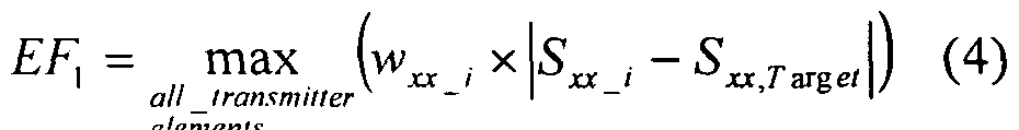
EF = max (wj χ (Actual, - GoaU) (2)
allCriteria
This relative simple definition is commonly used in manual transmitter optimization, in which no specialized hardware or software is used for calculating EF.
For multi-channel RF transmitter fabrication, and in most numerical investigations, the optimization criteria for trans¬ mitter performance at the circuit level are based on the fol- lowing so-called "scattering" parameters [WO 2010/110881 Al] : a) the element reflection coefficient Sxx, estimated as the ratio of the voltage associated with an incident wave applied to the input of the element labelled "x" to that of the wave reflected from the same input; and
b) the reflection coefficient Sxy estimated as the ratio of the voltage of the incident wave applied to the input of the element labelled "x" to that reflected from the element la¬ belled x,y". These quantities are determined at the desired frequency FMRI for a given load, which may be a phantom or a subject. Sxx and Sxy are quantities defined in the frequency domain, because they are measured (or numerically estimated) in the course of a frequency sweep. Therefore the term "frequency-domain optimization" is used when a transmitter is optimized using Sxx and Sxy.
A commonly used set of optimization criteria is defined (at the desired frequency FMRI) as: a) the actual Sxx must be less than a target Sxx,Target, for each transmitter element; b) the actual Sxy must be less than a target Sxy, Target / for each de- coupled element pair. Hence
EF= Σ W» J X |5« J - 5«.7·«β
all transmitter «Γ
elements
( 3 )
Wxy_ i
 ~ Sjtyjargei l
all decoupled
pairs of transmitter elements
with :
Wvx i. : Weighting factor for the reflection coefficient Sxx_ for the individual transmit element "i",
wxy i: Weighting factor for the reflection coefficient SXY_
for the "i" decoupled pair of transmit elements
S-:, Target : Predetermined target value for each element reflec¬ tion coefficient Sxx_i
SXy, Target : Predetermined target value for each reflection coef ficient Sxv i
For manual optimization, one commonly minimizes simultaneously two error functions
 e ements

However this strategy can be seriously hampered by a lack of reliable information regarding RF field performance, i.e. Bi+v/ VPtransmitf f°r specific excitation modes. In general the transmitter elements are not ideally decoupled, i.e. all of Sxy_i are greater than zero. Because
P rej, t,ransmit„ter =a" SH Sxa (V6)/ (where S - entire scattering matrix, subscript " " represents complex conjugate transpose), ref_transmitter is also non-zero, and consequently Pv depends on the excitation mode (i.e. input excitation vector a) . For a particular mode (or several modes) Pref_transmitter can amount to a substantial fraction of Ptransmit- This results in
severe degradation of the transmitter's efficiency

Due to complexity of equation 6, there is no simple relation- ship between EF ( EF\ and EFz) obtained by equation 3 (or 4 and 5) and Pref_transmitter · By contrast, for example in a multi- row transmitter, the Sxy between elements in the same row of a multi-row transmitter, and Sxy between elements in differ¬ ent rows, have distinct influences on Pref_transmitter (and conse- quently on Bj+v Ptransmit) . It has been reported that an transmitter with significantly coupled elements in the same row and good decoupling of elements belonging to different rows provides transmit performance similar to or even better than an transmitter with the same element geometry and fully de- coupled elements [M. Kozlov, R. Turner: -"Analysis of RF transmit performance for a 7T dual row multichannel MRI loop array, " Proceedings of 33rd Annual International Conference of the IEEE E BS , Boston, USA, p. 547-553, August 2011] . In general, the scattering parameters (as defined by the entire S parameter matrix) are load dependent. Thus to maintain a satisfactory level of Sxx and Sxy below Sxx_target and Sxy_targetf in most cases optimization has to be performed again for each load (subject) . This is relatively easy to perform for trans- mitters with a moderate number of elements, but for large number of elements, and especially for a multi-row transmitter, the full procedure is challenging and lengthy, and may not even converge. It has also been reported that single-row multi-channel transmitters often provide the best Bj+v/ V-?transmit for a given excitation mode (e.g. a given static RF shim configuration) if the transmitter is optimized by means of minimization of
Pre. transmitter when only this mode is excited [WO 2011/029452 Al] . Here EF is defined as

When the reflected power minimization approach is applied to transmitter, with a multiple rows in the Z direction, with no dedicated decoupling network within each row, it only succeeds as a transmitter optimization method if axially adja- cent transmitter rows are explicitly decoupled, for example by an inductive decoupling network [M. Kozlov, R. Turner:
"Analysis of RF transmit performance for a 7T dual row multichannel MRI loop array, " Proceedings of 33rd Annual International Conference of the IEEE EMBS, Boston, USA, p. 547- 553, August 2011] .
For a multi-row transmitter EF is defined as
 where Pref_row_i is the power reflected by row i, and
wr_i is the weighting factor for the reflected power of the given transmitter row. Pref_transmi ter is commonly referred as a time-domain quantity because the reflected power was historically measured (or nu¬ merically estimated) during a time sweep. Therefore the term "time-domain optimization" is used when Pref_transmitter is mini¬ mized, although state-of-the-art measuring devices and simu- lation software can also obtain Pref_transmitter during a fre¬ quency domain sweep (e.g. using equation 6). It should be noted that Pref_transmitter optimization for a given mode provides good load independence [M. Kozlov, R. Turner: "Analysis of
Transmit Magnetic Field Homogeneity for a 7T Multi-channel MRI Loop Array,", Progress In Electromagnetics Research Symposium Proceedings, Marrakesh, Morocco, p. 1607-16011, March 2011] but may result in sub-optimal performance for other modes.
The maximum value within a load (subject) of the local specific absorption rate (SAR) , and the global SAR, significantly depend on the subject properties, and also on the specific combination of RF amplitudes and phases of individual transmit channels. Consequently, use of any arbitrary mode (arbitrary combination of RF amplitudes and phases of indi¬ vidual transmit channels) requires a reliable real-time SAR monitoring system and SAR prediction for a given subject. The hardware infrastructure required for this is absent from present-day commercially available MRI scanners, resulting in their sub-optimal usage, especially for clinical applications, in which the SAR values permitted by software and hardware constraints are typically much smaller than strictly required for patient safety.
Provision of a limited number of excitation modes (e.g. static RF shimming combinations) is much less complicated and less expensive than enabling arbitrary mode excitation, with its requirement of specialized hardware and software. For this reason, the strategy has been proposed to use multielement transmitters (multi-row if required) to improve the RF homogeneity, performance and load independence, while using only a limited number of excitation modes [M. Kozlov, R. Turner: "Analysis of RF transmit performance for a multi-row multi-channel MRI loop array at 300 and 400 MHz", Proceedings of the Asia-Pacific Microwave Conference 2011, Melbourne, Australia, p. 1190-1193, December 2011.].
Optimization of a multi-channel near-field RF transmitter in numerical domain and by real fabrication process can be based on exactly the same procedure, because RF circuit and 3-D EM co-simulation allow one to follow the transmitter fabrication stages. In brief, the co-simulation approach entails:
1) substitution of all variable transmitter components (tune, match, decouple networks, etc.) by ports during the simulation of the 3D-EM model, which included a) all transmitter construction details for the resonance elements, b) the load (e.g. human body model), and c) transmitter environ¬ ment (e.g. MRI scanner gradient shield, magnet bore, etc), all simulated with precise dimensions and material electrical properties ;
2) reconnection the variable components during simulation of RF circuit (e.g. MRI scanner circuit);
3) obtaining network component values by circuit optimiza¬ tion;
4) a simple computation (weighted sum of already calculated quantities) of the final 3D electromagnetic field distribu- tion; and
5) finally calculation of transmitter properties (e.g. RF field performance, etc.).
Stage #1 corresponds to fabrication of the transmitter ele- ments and their assembly in the final transmitter geometry.
The stage #2 corresponds to soldering-in of the variable components . Stage #3 corresponds to transmitter optimization procedure.
Stage #4 mimics the measuring of transmitter fields (e.g. obtaining of B1+ mapping by an MRI experiment) .
Stage #5 corresponds post-processing of transmitter experimental data for calculating transmitter properties.
WO 2011/029452 Al discloses an optimization method for a mul- ti-channel transmitter, wherein an optimization criterion is calculated based on the reflected power only.
Objective of the invention It is an objective of the present invention to provide a reliable and relatively fast method for multi-channel near- field RF transmitter (e.g. MRI transmitter) optimization, and on-site usage, which supports multi-mode (e.g. a set of static RF shims) excitation for several loads (subjects), without transmit performance degradation (in opposite with performance improvement for most of excitation modes) for these modes and loads (subjects) . The method is based on use of a multi-mode, multi-load, and multi-domain optimization. A further objective of the invention is to provide a method for load (subject) independence of transmitter transmit properties and maintenance (keeping without essential decrease) of safety excitation efficiency when in time interleave excitation is applied. These objectives are achieved with methods and devices as defined in the independent claims. Advantageous embodiments and applications of the invention are defined in the dependent claims . Summary of the invention
According to the first aspect of the invention, a method is provided for the optimization of performance of a multichannel near-field RF transmitter, which is used for excita-
tion of at least one mode, in one subject. The method improves RF power efficiency, keeping optimal RF homogeneity (or RF focusing into given volume of interest (VOI) if it is requested) . All transmitter elements are simultaneously excited with a specific RF power signal of fixed amplitude and phase, as it is required for obtaining optimal RF homogeneity or RF focusing for given VOI. In this method, optimization of RF power efficiency is achieved by simultaneous usage of time and frequency domain optimization of the transmitter:
EF = w x\S .—S T
all Iransmiiier
elements
all decoupled
pairs nf transmitter elements
+ Wrefl X | ^Re./? _iran «fer |
with :
EF: Optimization criterion
wx:<_i: Weighting factor for the reflection coefficient
Sx:_i for the individual transmit element "i",
Wvy_i : Weighting factor for the reflection coefficient
SXy_i for the "i" decoupled pair of transmit elements
S , Target^ Predetermined target value for each element reflection coefficient S:<x_i
Svy, Target: Predetermined target value for each reflection co¬ efficient Sxy_i
Wrefi : Weighting factor for reflected power of the entire multi-channel transmitter
*Refl transmitter : reflected power of the entire multi-channel
transmitter .
The inventive step utilizes the fact that Equation 6 provides calculation for the third term of the EF, measurement (or calculation in numerical domain) of S parameter matrix is sufficient for EF estimation and performing entire optimiza- tion.
As its principal advantages, this inventive method ensures that transmit performance is optimal for given excitation mode .
According to the second aspect of the invention, a method is provided for the optimization of performance of a multichannel near-field RF transmitter, which is used for excitation of at least two modes, in one subject. The method im- proves RF power efficiency, keeping optimal RF homogeneity
(or RF focusing into given volume of interest (VOI) if it is requested) . All transmitter elements are simultaneously excited with a specific RF power signal of fixed amplitude and phase, during given mode excitation, as it is required for obtaining optimal RF homogeneity or RF focusing for given
VOI. In this method, optimization of RF power efficiency is achieved by simultaneous usage of time and frequency domain optimization of the transmitter, and optimization transmitter to ensure minimum of Prefi transmitter is obtained for all given excitation modes.
all transmitter
elements
+ all decoupled > »v_, *|
pairs of transmitter elements m i γ Rc β transmitter \
all modc
with :
EF: Optimization criterion
w..,- -: : Weighting factor for the reflection coefficient Sxx i for the individual transmit element w,. Weighting factor for the reflection coefficient Sxy_i for the "i" decoupled pair of transmit elements
, Target Predetermined target value for each element reflection coefficient Sxx i
'. , Target · Predetermined target value for each reflection coefficient Sx.y_i
W„ Weighting factors for reflected power of the entire multi-channel transmitter for given transmitter^: reflected power of the entire multi-channel transmitter for given transmit mode "i".
According to the third aspect of the invention, a method is provided for the optimization of performance of a multichannel near-field RF transmitter, which is used for excitation of at least two modes, in at least two subjects. The method improves RF power efficiency, keeping optimal RF homogeneity (or RF focusing into given volume of interest (VOI) if it is requested) . All transmitter elements are simultaneously excited with a specific RF power signal of fixed amplitude and phase, during given mode excitation, as it is required for obtaining optimal RF homogeneity or RF focusing for given VOI. In this method, optimization of RF power effi- ciency is achieved by simultaneous usage of time and frequency domain optimization of the transmitter, simultaneous optimization for all loads (subjects), optimization transmitter to ensure minimum of Prefi_transmitter is obtained for all given excitation modes.
e
 ements
EF = X + W X (11)
oil decoupled
pairs of transmitter elements
Wm X|^Re fl _ transmitter _
all mode.r with :
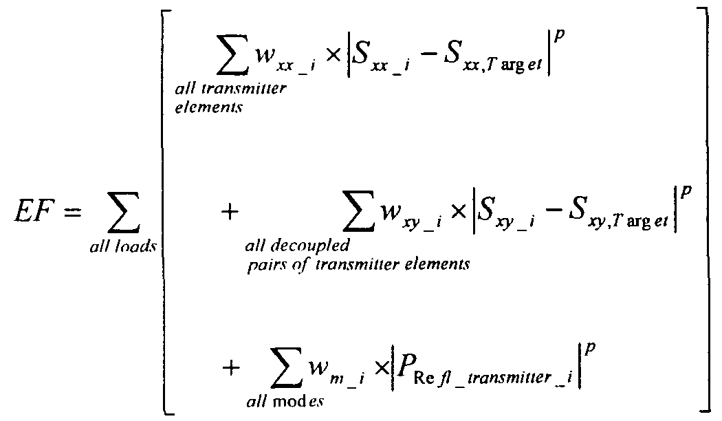
EF: Optimization criterion
w _i : Weighting factor for the reflection coefficient Sxx_i for the individual transmit element xy_i-. Weighting factor for the reflection coefficient Sxy i for the "i" decoupled pair of transmit elements
Sv , Ta ge : Predetermined target value for each element reflection coefficient Sxx_i
Sxy, Target : Predetermined target value for each reflection coefficient Sxy_i
wm_i : Weighting factors for reflected power of the entire multi-channel transmitter for given transmit mode "i"
Pp.efi_transmitter_i : reflected power of the entire multi-channel transmitter for given transmit mode "i".
The quantities Sxx i, Sxy_i, PRefi_transmitter_i are dependent on the transmitter loading. Thus EF represents the sum over all loads. The index for load is not included in equation 11 to assist readability of the equation.
According to the 4st aspect of the invention, a method is provided for the optimization of performance of a multi-
channel near-field RF transmitter, which is used for excitation of at least one mode, in at least one subject in time interleave RF excitation. The method improves RF power effi¬ ciency, keeping optimal RF homogeneity (or RF focusing into given volume of interest (VOI) if it is requested) and safety excitation efficiency. All transmitter elements are excited sequentially in time with a specific RF power signal of fixed amplitude and phase, during given mode excitation, as required for obtaining optimal RF homogeneity or RF focusing for given VOI. In this method, optimization of RF power efficiency and maintenance of safety excitation efficiency are achieved by simultaneous usage of time and frequency domain optimization of the transmitter, simultaneous optimization for simultaneous and in time interleave excitation.

(12)

EF: Optimization criterion
Weighting factor for the reflection coefficient Sxx_i for the individual transmit element "i"
w, y_-- ' Weighting factor for the reflection coefficient Sxy for the decoupled pair of transmit elements
S Target: Predetermined target value for each element reflection coefficient SXX I
SX Y, Target: Predetermined target value for each reflec¬ tion coefficient SXY i
wt i: Weighting factors for reflected power of the entire multi-channel transmitter for given interleave stage "i"
•PRefi transmitter is_i '· _Ref1ected power of the multi-channel trans¬ mitter during given interleave stage "i"
•PTransmit: Power transmitted by the multi-channel
transmitter
NiS: Number of interleave stages.
Detailed description of the invention
The present invention provides an improved transmitter performance at a specified frequency and for given excitation modes and loads (subjects) ; and provides performance which is highly independent of the transmitter loading. The design of the improved optimization procedure is a unique achievement and represents an unpredicted advance in this technical field.
For given transmitter geometry and set of operation modes, only the circuit optimization step has an influence on the transmitter performance. To overcome the limitations of opti¬ mization in each domain, time and frequency, and improve transmitter load independence we implemented multi-mode, multi-load, and multi-domain optimization of multi-channel near- field RF transmitters.
A new set of optimization criteria, defined at transmitter operation frequency (e.g. MRI) consisted of individually weighted criteria:
a) the actual Sxx must be less than a target Sxx,Targets f°r each transmitter element;
b) the actual Sxy must be less than a target Sxy,Target/ for each decoupled element pair; and
c) for minimization to zero of Pref_transmitter n each operation mode. EF is calculated on base of data for set of loads (e.g. set of subjects) that represents as close as possible expected operation loading conditions. all transmitter
elements
EF= ∑ xy I I y /
all loads all decoupled
pairs of fransmiuer elements
+ Re fl _ transmitter _ i |
all mod es
For example, the new optimization procedure results in 8 or 24 criteria for Sxx (i.e. all_transinitter_eleinerit is equal to 8 or 24), and 8 or 72 criteria for Sxy (i.e.
all_decoupled_pairs_of_transmitter_elements is equal to 8 or 72). For both transmitters, components to be optimized are: the matching capacitor for each element matching network, the tuning capacitor for each element tuning network, mutual inductance between decoupling inductors for each decoupling network. This resulted in 24 or 120 optimization variables for the single row transmitter, or the triple row transmitter respectively .
Initial guesses are made, based on numeral simulation experience or experimental knowledge, for the values of adjustable multi-channel transmitter lumped elements, as well as the range over which adjustable elements can be varied.
For the single row transmitters, each optimization can be performed in two steps: 3000 random tries, followed by "Qua- si-Newton" optimization until no further improvement was possible. This ensures that the global minimum condition had been found. It takes less than 1 minute to compute the values of all variable components for a given set of individually weighted criteria. All weight factors can be equal to 1 for the first optimization trial. If Pref_transmitter in one mode was still more than 5% of Ptransmit the weight factor of the crite- rion for Pref_transmitter was step by step increased by 1.0 until the worst Case Value Of Pref_transmitter Was leSS than 5% Of Ptransmit for all excitation modes.
For double and triple row transmitters, the optimization ap- proach described above could be insufficient to provide global optimization, because the number of independent optimization variables is too high for the entire optimization space to be covered by 3000 random tries. Simply increasing the number of random tries did not help, because the required number of tries becomes so large that optimization time becomes unacceptably long. To keep optimization time at a rea¬ sonable level (a few minutes) , a two stage optimization approach is implemented for transmitter with cylindrical (or close to cylindrical symmetry) . Despite the asymmetry of the human head model, the cylindrical symmetry of the elements in each transmitter row ensured that the value of adjustable el¬ ements of the tuning and decoupling networks were relatively similar, within the same row. Thus preliminary values of optimization variables are obtained by performing the first stage optimization with independent variables grouped for each row and each type of network. This approach reduces number of independent optimization variables from 120 to 15 for the triple row transmitter. As a result 3000 random tries be-
comes reasonable for approaching preliminary values of optimization variables.
At the second stage, using the "Quasi-Newton" method, optimi- zation values for all ungrouped independent variables are ob¬ tained, when the optimizer reports that no further improvement is possible. To ensure (to some extent) that the two stage optimization approached global minimum condition, a multi-start strategy has to be used. This consists of re- running both stages of the optimization several (e.g. five) times with different initial conditions. If the data spread was small (less than 5% peak to peak variation of both optimization variables and quantitative results) then the multi- start was considered to be sufficient for obtaining optimized value of independent variables with about 5% uncertainty. If the data spread was not small, the multi-start procedure is performed 5 times more. When the best optimization of both multi-start tries reaches similar end error values, and the peak-to-peak variation in their optimization variables and results is less than 5%, the optimization procedure is stopped, and values from the best optimization try are considered as the final result. Each dual stage optimization takes about 2 minutes: thus, in most cases, the entire multi- row transmitter circuit optimization require about 10 min- utes, a much shorter time as compared with the about one day taken for 3D-EM simulation of a multi-row transmitter using an up-to-date Dell Precision T7500 Workstation with 64 GB RAM and 12 cores. The number of individual transmitter elements (coils) that need to be excited simultaneously may exceed the number of independent transmit channels available at the MRI scanner. A solution - excitation of transmitter elements that are interleaved in time - has been successfully implemented. However,
this important experimental work has not yet provided data regarding safety (primary safety excitation efficiency
Bi+v/ sAKiog) implications. To keep the same nuclear spin rotation, and correspondingly Bi+Vf the amplitude of the excitation signal must be in¬ creased by the number of interleaves used in the excitation (Wis) r provided that there is zero time delay between steps. This results in an increase of power transmitted to each transmitter coil element by a factor of NIS, compared with simultaneous excitation of all transmitter elements. The transmitter is a linear system and its E- and magnetic (B) fields can be obtained as the linear complex superposition of the fields for each individual transmitter element obtained for unit excitation, after weighting by the corresponding elements of the voltage excitation vector. But none of the transmitter's scalar field derived quantities, for instance power loss density, SAR or power deposited in given tissue, can be superposed linearly.
Two major factors, to some extent correlated, determine the power deposited in the entire tissue (Pioad) / the corresponding global SAR, and its distribution in a multi-row transmit¬ ter. These are a) the law of conservation of energy; b) the constructive and destructive interference of ^-fields. Due to the first factor, since the transmitters are not ideally de¬ coupled, the power reflected by the entire transmitter
( -Prefi_transmitter) , and consequently Pioad, which must always be less than the transmit power ( Ptransmit) r depend on the excita- tion vector. Considering the second factor, the £-field superposition cannot only be constructive, because if this were the case ioad would approach a value equal to Nelem- Ptransmit > where Neiem is the number of elements in the transmitter, thus invalidating the law of conservation of energy. In an inter-
esting extreme case, the more destructive the E-field interference between transmitter elements, the greater the power reflected by the entire transmitter. In the worst case condition, interleaved excitation resulted in an increase of Pioad and SARi0g (decrease safety excitation efficiency) by a factor of NIS. However, a usefully different behavior is discovered for a specific configuration. With interleaved excitation, element coupling can result in signifi- cant power reflected by transmitter at each interleave stage (■Prefi transmitters) · If the excitation profiles from each inter¬ leave are well spatially separated, large Prefi_transmitter_is re¬ sults in that the power deposition, SARioq, and safety excitation efficiency of interleaved excitation remain similar to those for simultaneous excitation.
In the context of the invention, the term "multi-channel transmitter" preferably refers to a transmitter comprising several radiative coil elements, wherein each radiative coil element preferably comprises an individual input forming an input channel of the multi-channel transmitter. Therefore, the input channels of the multi-channel transmitter can be driven with individual excitation signals. The radiative coil elements of the multi-channel transmitter can be arranged in a row or in a column. Alternatively, the coil elements can be arranged in a transmitter comprising several rows of coil elements and several columns of coil elements .
Brief description of the drawings
Figures 1A and lb show a flowchart illustrating an optimization method according to the invention.
Figure 2A shows the frequency dependence of the reflection coefficient Sxx for a frequency domain optimization, Figure 2B shows the frequency dependence of the reflection coefficient Sxy for a frequency domain optimization,
Figure 2C shows the frequency dependence of the reflection coefficient Sxx for a dual domain optimization both in the frequency domain and in the time domain.
Figure 2D shows the frequency dependence of the reflection coefficient Sxy for a dual domain optimization both in the frequency domain and in the time domain.
Figure 3A shows a Monte Carlo histogram of the ratio
 n percent for the CP1 mode and a fre¬ quency domain optimization. Figure 3B shows a Monte Carlo histogram of the ratio
Prefi_transmitter/Pti:ansmit i percent for the CP2 mode and a fre¬ quency domain optimization.
Figure 3C shows a Monte Carlo histogram of the ratio
i5refi_transmitter ^transmit in percent for the CP1 mode and a dual domain optimization.
Figure 3D shows a Monte Carlo histogram of the ratio
rrefl transmitter / -Ptransmit in percent for the CP2 mode and a dual domain optimization.
Figure 4 shows the investigated single row transmitter comprised of 8 channels with identical rectangular loops of
length 120 mm and the angular size 40 degrees, mounted on a cylindrical acrylic former with diameter of 280 mm.
Figure 5 shows the investigated triple-row transmitter, each non-overlapped row is comprised by 8 identical rectangular loops of length 70 mm and the angular size 40 degrees, mounted on a cylindrical acrylic former with diameter of 280 mm.
Detailed description of the drawings
In the following, the flowcharts shown in Figures 1A and IB are described.
In a first step SI, excitation modes are defined for excita- tion of the multi-channel transmitter. Further, loads (subjects) of the multi-channel transmitter are defined and circuit level optimization criteria are determined.
In a second step S2, a decision is made whether the optimiza- tion is performed in numerical domain or using measurements of a real multi-channel transmitter.
In the following, steps S3-S6 are explained which refer to the optimization using measurement data of a real multi- channel transmitter.
In step S3, the coil elements of the multi-channel transmit¬ ter are manufactured. Then, in step S4, the other components (e.g. trim capacitors, decoupling networks, etc.) of the multi-channel transmitter are soldered.
In step S5, the reflection coefficients Sxx of all transmit¬ ter elements and the reflection coefficients Sxy of all decoupled pairs of transmitter elements are measured for given loads .
The reflection coefficients Sxx represent a signal ratio between an incident wave applied to the x-th coil element of the multi-channel transmitter and a resulting wave reflected from the x-th coil element of the multi-channel transmitter.
The reflection coefficients Sxy represent a signal ratio between an incident wave applied to the x-th coil element of the multi-channel transmitter and a resulting wave reflected from the y-th coil element of the multi-channel transmitter.
In step S6, the power PRefi transmitter reflected by the entire transmitter, or by each transmitter row is measured or calculated using S parameter data for given loads (subjects) and excitation modes.
In the following, the corresponding steps S7-S10 are explained which relate to the calculation of the aforementioned data in numerical domain. In step S7, three-dimensional electro-magnetic simulations of the multi-channel transmitter are calculated with given loads ( subj ects ) .
Then, in step S8, RF circuit simulations of the multi-channel transmitter with given loads are calculated.
In step S9, the element reflection coefficients Sxx and the reflection coefficients Sxy of all decoupled pairs of transmitter elements are extracted for given loads.
Further, in step S10, the reflected power is calculated for given loads (subjects) and excitation modes.
In step Sll, an error function EF is calculated wherein the error function EF is an optimization criterion. The error function is calculated on the basis of the reflected power PRefi transmitter , the reflection coefficients Sxx and the reflec¬ tion coefficients Sxy according to the following formula:
Then, in step S 12 , the value of the error function E F is compared with a predetermined target value E FTarget -
If the actual value of the error function EF is smaller than the predetermined target value EFTarget r then it is determined in step S 1 6 that the multi-channel transmitter is ready for use .
Otherwise, step S 13 estimates the adjustment direction for variable components (e.g. trim capacitors) of the multichannel transmitter. In step S 14 , the variable components (e.g. trim capacitors) are adjusted to new values.
In step S15, it is determined whether a recalculation is made in the numerical domain or not, if so, the method continuous with step S8 in Figure 1A. Otherwise, the method continuous with step S4 in Figure 1A.
Example data
The geometry of the single and multi-row loop-based transmitters that we investigated is described in [M. Kozlov, R.
Turner: "Analysis of RF transmit performance for a multi-row multi-channel MRI loop array at 300 and 400 MHz", Proceedings of the Asia-Pacific Microwave Conference 2011, Melbourne, Australia, p. 1190-1193, December 2011; M. Kozlov, R. Turner, "Influence of loop array geometry on near field transmit properties at 300 MHz", Proceedings of 2011 IEEE International Symposium on Antennas and Propagation, Spokane, USA, p. 1715-1718, July 2011]. For example: a) the investigated single row transmitter is comprised of 8 channels with identical rectangular loops of length 120 mm and the angular size 40 degrees, mounted on a cylindrical acrylic former with diameter of 280 mm (cf. Figure 4); b) the investigated triple- row transmitter, each non-overlapped row is comprised by 8 identical rectangular loops of length 70 mm and the angular size 40 degrees, mounted on a cylindrical acrylic former with diameter of 280 mm (cf . Figure 5) . The realistic 3-D EM model of the transmitters included all construction details for the resonance elements, simulated with precise dimensions and material electrical properties. The loads utilized were the multi-tissue Ansoft human body models, cut in the middle of the torso, with different scaling factors: a medium-size head #1 with scaling X=0.9, Y=0.9, Z=0.9, a large-size (almost fully occupying the transmitter volume when the diameter was 250 mm) head #2 with scaling X=0.95, Y=0.975, Z=0.9, and a small-size head #3 with scaling X=0.85, Y=0.85, Z=0.9. To in-
vestigate transmitter transmit performance sensitivity to load position, the latter was varied.
The RF circuit simulator was Agilent ADS 2011.10, and Ansoft HFSS 14 was chosen as the 3-D EM tool.
For the single row 8-element transmitter, or for the triple row transmitter, where each non-overlapped row is correspondingly comprised of 8 identical rectangular loops, components to be optimized are: the matching capacitor for each element matching network, the tuning capacitor for each element tun¬ ing network, the decoupling capacitor or mutual inductance between decoupling inductors for each decoupling network. This results in 24 or 120 optimization variables for the sin- gle row transmitter, or the triple row transmitter respectively.
Initial guesses are made (based on numeral simulation, experience, or experimentally derived knowledge) for the values of adjustable lumped elements, as well as the range over which adjustable elements can be varied.
For the single row transmitters, each optimization can be performed in two steps: 3000 random tries, followed by "Qua- si-Newton" optimization until no further improvement was possible. This ensures that the global minimum condition has been found. It takes less than 1 minute to compute the values of all variable components for a given set of individually weighted criteria. All weight factors can be equal to 1 for the first optimization trial. If Prefi_transmitter in one mode was still more than 5% of ^transmit the weight factor of the criterion for i3refi_transmitter was step by step increased by 1.0 until the worst case value of Prefi_transmitter was less than 5% of
■^transmit for all excitation modes.
For double and triple row transmitters, the optimization approach described above could be insufficient to provide global optimization, because the number of independent optimiza- tion variables is too high for the entire optimization space to be covered by 3000 random tries. Simply increasing the number of random tries does not help, because the required number of tries becomes so large that the optimization time becomes unacceptably long. To keep optimization time at a reasonable level (a few minutes), a two stage optimization approach is implemented for transmitters with cylindrical (or close to cylindrical symmetry) . Despite the asymmetry of the human head model, the cylindrical symmetry of the elements in each transmitter row ensures that the value of adjustable el- ements of the tuning and decoupling networks are relatively similar, within the same row. Thus the preliminary values of optimization variables are obtained by performing the first stage optimization with independent variables grouped for each row and each type of network. This approach reduces the number of independent optimization variables from 120 to 15 for the triple row transmitter. As a result, the use of 3000 random tries becomes reasonable for approaching the preliminary values of optimization variables. At the second stage, using the "Quasi-Newton" method, optimized values for all ungrouped independent variables are obtained when the optimizer reports that no further improvement is possible. To ensure (to some extent) that the two stage optimization approaches global minimum condition, a multi- start strategy should be used. This consists of re-running both stages of the optimization several (e.g. five) times with different initial conditions. If the data spread is small (less than 5% peak to peak variation of both optimization variables and quantitative results) then the multi-start
is considered to be sufficient for obtaining optimized values of independent variables with about 5% uncertainty. If the data spread is not small, the multi-start procedure is performed 5 times more. When the best optimization of both mul- ti-start tries reaches similar final error values, and the peak-to-peak variation in their optimization variables and results is less than 5%, the optimization procedure is stopped, and values from the best optimization try are considered as the final result. Each dual stage optimization takes about 2 minutes: thus, in most cases, the entire multi- row transmitter circuit optimization require about 10 minutes, much faster than the approximately one day required for 3D-EM simulation of a multi-row transmitter using an up-to- date Dell Precision T7500 Workstation with 96 GB RAM and 12 cores.
The time-domain only optimization, guided by EF defined in (5), resulted in Prefi_transmitter =0, and the best performance for optimization of the excitation mode. In other modes
Prefi_transmitter could approach 40% of Ptransmi t and performance was sub-optimal .
In the CP1 mode, optimization in the frequency domain resulted in relatively small Prefi_transmitter (less than 10% of
•Ptransmit) ? thus ensuring almost the best performance. This was guided by EF defined in (1) with only adjacent elements included in the decoupled element pair list, Sxx,Target= ~ 30 dB, Sxy,Target= ~20 dB and all weighting factors equal to 1. However, in the CP2 mode, Prefi_transmitter was significantly larger (mostly more than 25% of Ptransmit) · Consequently the transmit performance in the CP2 mode was significantly reduced. For a given mode B2 + homogeneity was similar after both optimizations .
Extension of the decoupled element pair list by including also all second-neighbour pairs did not essentially improve CP2 mode transmit performance, compared with the original frequency domain optimization.
Dual-domain optimization resulted in negligible Prefi_transmitter (less than 3% of PCransmit) for both CP1 and CP2 modes, pro¬ vided that coupling to the second-neighbour elements was less than -9 dB after frequency domain optimization. In this condition, the coupling between the second-neighbour elements decreased by 4 to 8 dB, but the single resonance element matching became relatively poorer (in the range -10 dB to -15 dB) , and adjacent element coupling increased by 3 to 5 dB . Thus, despite giving the best transmit performance in the desired excitation modes, both the frequency dependence of Sxx (i.e. element matching) and Sxy (i.e. the coupling between adjacent elements) resemble the corresponding frequency dependence of a sub-optimal, badly tuned transmitter (Fig. 2A-2D) . To mimic a sub-optimally tuned transmitter, obtained after in the frequency domain optimization, SXX(Target and Sxy,Target were changed to be -10 dB and -12 dB respectively. Starting the optimization from several different initial conditions, a set of optimization results was obtained for several transmitter geometries. Despite the very similar visual appearance of the frequency dependence of element matching and coupling between adjacent elements for all tuning parameters (plotted in dB scale) , the transmit performance showed highly significant variation, from very sub-optimal ( Prefi_transmitter about 30% of Ptransmit) to nearly the best ( Prefi_transmitter ~0) . This finding has a rational explanation: from (4) Prefi_transmittet depends on all the interactions within the transmitter (not only the subset of interactions described by element matching and coupling between adjacent elements), and also on the phases of
coupling between adjacent elements, which are rarely analysed.
It is becoming increasingly important to be able to generate not only several fundamental excitation modes, but also to have ability to adjust amplitude and phase of excitation signals for given fundamental excitation mode (to apply so- called static RF shimming) , in order to obtain better homogeneity in a given VOI or part of VOI .
Figures 3A-3D show Monte Carlo histograms of a ratio
transmitter
 in percent.
Figures 3A and 3C refer to the first circular polarization (CP1) mode, while Figures 3B and 3D refer to the second circular polarization (CP2) mode. Further, Figure 3A and 3B illustrate a frequency domain optimization, while Figures 3C and 3D illustrate a dual domain optimization. By Monte Carlo analysis, using 4000 trials with uniform +/-
30% variation of phase for each excitation signal for CP1 and CP2 modes, the influence of dual-domain optimization on transmitter performance after static RF shimming was investigated. These results allow us to conclude that dual-domain optimization improves not only performance in fundamental CP1 and CP2 modes, but also the performance after static RF shimming has been performed for these fundamental modes (Figures 3A-3D) . Similar to single row transmitter, the dual-domain optimization of dual and triple row transmitters resulted in: a) significant reduction of Prefi_transmitter for all modes, provided that coupling to the second-neighbour elements in all direction was less than -9 dB after frequency domain optimization,
b) S parameter matrix looked like a "badly" tuned transmitter, and c) improved performance after static RF shimming around given fundamental modes. However, the larger the number of transmitter elements, the larger is the worst case value of Prefi_transmitter · For example, for a triple row transmitter, Prefi_transmitter could not be reduced to below 5% of ^transmi in some excitation modes.
This novel optimization procedure has no practical effect on safety excitation efficiency, defined as
 or the peak location of the specific absorption rate averaged over 10 gram (SAR10g) . From the MRI perspective, it is the level of safe excitation efficiency that defines MRI scanner performance, not the peak SARiog, which increases when the new opti- mization procedure is used, simultaneously with an increase of Si+V.
Although the invention has been described with reference to the particular arrangement of parts, features and the like, these are not intended to exhaust all possible arrangements of features, and indeed many other modifications and variations will be ascertainable to those of skill in the art.
Claims
Claims
1. Method for optimization of a performance of a multichannel transmitter comprising several transmit elements, particularly in a magnetic resonance imaging device, wherein the method comprises the following steps:
a) Exciting the transmit elements of the multi-channel
transmitter by electric excitation signals comprising a specific power, wherein the power of the excitation signals is partially reflected by the transmit elements of the multi-channel transmitter,
b) Determining a reflected power which is reflected by the multi-channel transmitter during excitation of the transmit elements,
c) Determining reflection coefficients Sxx of the multichannel transmitter, wherein said reflection coefficients Sxx represent a signal ratio between an incident wave applied to the x-th transmit element of the multichannel transmitter and a resulting wave reflected from the x-th transmit element of the multi-channel- transmitter,
d) Determining reflection coefficients Sxy of the multichannel transmitter, wherein said reflection coefficients Sxy represent a signal ratio between an incident wave applied to the x-th transmit element of the multichannel transmitter and a resulting wave reflected from the y-th transmit element of the multi-channel- transmitter,
e) Calculating a performance criterion representing the performance of the multi-channel transmitter, wherein the performance criterion is based on
el) the reflected power and
e2) the reflection coefficients Sxx and
e3) the reflection coefficients Sxy,
f ) Tuning the multi-channel transmitter so that the performance criterion is optimized.
2. Method according to claim 1, wherein the optimization criterion is calculated according to the following formula and the multi-channel transmitter is tuned so that the opti¬ mization criterion is minimized: xx - S xx.Targel
all transmitter
elements
all
pa

Re f transmitter
with :
EF: Optimization criterion
Wv i > Weighting factor for the reflection coefficient
Sx x_i for the individual transmit element "i",
Wxy_i Weighting factor for the reflection coefficient
Sxy_i for the "i" decoupled pair of transmit el¬ ements
'xx, Target Predetermined target value for each element reflection coefficient Sxx i
'xy, Target Predetermined target value for each reflection coefficient Sxy_i
Wref1■ Weighting factor for reflected power of the entire multi-channel transmitter
•PRefi_transmitter : reflected power of the entire multi-channel
transmitter .
3. Method according to claim 2, wherein the method is performed for at least one excitation mode and only one load of the multi-channel transmitter. 4. Method according to claim 1, wherein the optimization criterion is calculated according to the following formula and the multi-channel transmitter is tuned so that the opti¬ mization criterion is minimized:
EF = w„ _,. x |S„_(. -S^ ^I
-S
 with:
with:
EF: Optimization criterion
wxx_i : Weighting factor for the reflection coefficient
Sxx_i for the individual transmit element "i" wxy_i : Weighting factor for the reflection coefficient
5xy_i for the "i" decoupled pair of transmit elements
Sxx,Target^ Predetermined target value for each element reflection coefficient Sxx_i
^xy, Target : Predetermined target value for each reflection coefficient 5xy i
wm_i: Weighting factors for reflected power of the entire multi-channel transmitter for given transmit mode "i"
^ efl transmitter i : reflected power of the entire multi-channel transmitter for given transmit mode "i".
5. Method according to claim 4, wherein the method is per¬ formed for at least two excitation modes and only one load of the multi-channel transmitter.
6. Method according to claim 1, wherein the optimization criterion is calculated according to the following formula and the multi-channel transmitter is tuned so that the opti¬ mization criterion is minimized: xS„ ,-S Targe/ 1
EF= ∑ + w ,-S.
+ w. Re
mode.v with :
EF: Optimization criterion
Wvv i ! Weighting factor for the reflection coefficient Sxx for the individual transmit element wxy_i Weighting factor for the reflection coefficient Sxy i for the "i" decoupled pair of transmit elements
'xx, Target Predetermined target value for each element reflection coefficient Sxx_
>xy, Target Predetermined target value for each reflection coefficient Sxy_i
Wn Weighting factors for reflected power of the entire multi-channel transmitter for given
P efi_transmitter_i : reflected power of the entire multi-channel transmitter for given transmit mode "i".
7. Method according to claim 6, wherein the method is performed for at least two excitation modes and at least two loads of the multi-channel transmitter.
Method according to claim 1, wherein
there is an interlaved excitation of the individual transmit elements of the multi-channel transmitter, the optimization criterion is calculated according to the following formula and
the multi-channel transmitter is tuned so that the optimization criterion is minimized:
\ p
YV I
all transmitter
elements xy x 5 xy, T arg et
all decoupled
pairs of transmitter elements
+ Wrcfl X Y Re fl transmitter ]
+ Transmit
Re fl _ transmitter _i _\
N,
E F : Optimization criterion
Weighting factor for the reflection coefficient Sxx i for the individual transmit element wxy i : Weighting factor for the reflection coeffi¬ cient Sxy i for the "i" decoupled pair of transmit elements
'χχ, Target Predetermined target value for each element reflection coefficient S
sxy, Target 1 Predetermined target value for each reflection coefficient Sxy_i
wt i : Weighting factors for reflected power of the entire multi-channel transmitter for given interleave stage "i"
^Befi transmitter is_i "· _Reflected power of the multi-channel trans¬ mitter during given interleave stage "i"
PTransmit: Power transmitted by the multi-channel trans¬ mitter
Nis: Number of interleave stages. 9. Method according to claim 8, wherein the method is performed for at least one excitation mode and at least one load of the multi-channel transmitter.
10. Method according to any of the preceding claims, wherein
a) the reflected power is measured for the entire multichannel transmitter, or
b) the reflected power is measured for each of the trans mitter element separately, or
c) the reflected power is measured for each row of multi channel multi-row transmitter separately.
11. Method according to any of the preceding claims, wherein
a) the excitation signals are radio frequency signals, and/or
b) the excitation signals all have a fixed amplitude and a fixed phase. 12. Method according to any of the preceding claims, wherein
a) the multi-channel transmitter is, after optimization, used at a certain operating frequency, and
b) the reflection coefficients Sxx and/or Sxy and/or the reflected power are determined at the operating frequency of the multi-channel transmitter.
13. Method according to any of the preceding claims, wherein
a) the reflection coefficients and the reflected power is numerically simulated so that the optimization criterion is numerically simulated without any transmitter measurements, or
b) the reflection coefficients and the reflected power is measured so that the optimization criterion is calculated based on transmitter measurements. 14. Method according to any of the preceding claims, wherein
a) the multi-channel transmitter is a single-row transmitter comprising a single row of transmit elements, or b) the multi-channel transmitter is a multi-row transmit- ter comprising a multiple rows of transmit elements.
+
Priority Applications (3)
| Application Number | Priority Date | Filing Date | Title |
|---|---|---|---|
| PCT/EP2012/001144 WO2013135251A1 (en) | 2012-03-14 | 2012-03-14 | A method for multi-mode, multi-load, and multi-domain optimization of a multi-channel near-field rf transmitter |
| US14/384,974 US9841477B2 (en) | 2012-03-14 | 2012-03-14 | Method for multi-mode, multi-load, and multi-domain optimization of a multi-channel near-field RF transmitter |
| EP12710871.0A EP2825897B1 (en) | 2012-03-14 | 2012-03-14 | A method for multi-mode, multi-load, and multi-domain optimization of a multi-channel near-field rf transmitter |
Applications Claiming Priority (1)
| Application Number | Priority Date | Filing Date | Title |
|---|---|---|---|
| PCT/EP2012/001144 WO2013135251A1 (en) | 2012-03-14 | 2012-03-14 | A method for multi-mode, multi-load, and multi-domain optimization of a multi-channel near-field rf transmitter |
Publications (1)
| Publication Number | Publication Date |
|---|---|
| WO2013135251A1 true WO2013135251A1 (en) | 2013-09-19 |
Family
ID=45894417
Family Applications (1)
| Application Number | Title | Priority Date | Filing Date |
|---|---|---|---|
| PCT/EP2012/001144 WO2013135251A1 (en) | 2012-03-14 | 2012-03-14 | A method for multi-mode, multi-load, and multi-domain optimization of a multi-channel near-field rf transmitter |
Country Status (3)
| Country | Link |
|---|---|
| US (1) | US9841477B2 (en) |
| EP (1) | EP2825897B1 (en) |
| WO (1) | WO2013135251A1 (en) |
Cited By (1)
| Publication number | Priority date | Publication date | Assignee | Title |
|---|---|---|---|---|
| USRE47026E1 (en) * | 2006-02-17 | 2018-09-04 | Regents Of The University Of Minnesota | High field magnetic resonance |
Families Citing this family (3)
| Publication number | Priority date | Publication date | Assignee | Title |
|---|---|---|---|---|
| US10997233B2 (en) * | 2016-04-12 | 2021-05-04 | Microsoft Technology Licensing, Llc | Multi-stage image querying |
| US10366859B2 (en) * | 2016-08-24 | 2019-07-30 | Varian Medical Systems, Inc. | Electromagnetic interference containment for accelerator systems |
| US11693078B2 (en) | 2021-02-08 | 2023-07-04 | Purdue Research Foundation | Hybrid spatial and circuit optimization for targeted performance of MRI coils |
Citations (48)
| Publication number | Priority date | Publication date | Assignee | Title |
|---|---|---|---|---|
| US4129822A (en) | 1975-04-24 | 1978-12-12 | Traficante D | Wide-band nuclear magnetic resonance spectrometer |
| US4320342A (en) | 1978-09-15 | 1982-03-16 | U.S. Philips Corporation | Magnet coil arrangement for generating linear magnetic gradient fields |
| US4638253A (en) | 1984-10-29 | 1987-01-20 | General Electric Company | Mutual inductance NMR RF coil matching device |
| US4721915A (en) | 1985-03-06 | 1988-01-26 | Siemens Aktiengesellschaft | High frequency antenna system for nuclear magnetic resonance tomography devices |
| US4725780A (en) | 1984-10-19 | 1988-02-16 | Mitsubishi Denki Kabushiki Kaisha | RF field generator and detector |
| US4731584A (en) | 1985-08-14 | 1988-03-15 | Picker International, Inc. | Magnetic resonance probe for operation at frequencies above self resonance |
| US4737718A (en) | 1985-08-19 | 1988-04-12 | U.S. Philips Corporation | Magnetic resonance imaging apparatus including a bird-cage r.f. coil |
| US4751464A (en) | 1987-05-04 | 1988-06-14 | Advanced Nmr Systems, Inc. | Cavity resonator with improved magnetic field uniformity for high frequency operation and reduced dielectric heating in NMR imaging devices |
| US4752736A (en) | 1986-07-22 | 1988-06-21 | The Regents Of The University Of California | Center fed QD MRI RF coil |
| US4780677A (en) | 1986-05-13 | 1988-10-25 | Elscint Ltd. | Probe for nuclear magnetic resonance systems |
| US4783641A (en) | 1987-08-13 | 1988-11-08 | General Electric Company | NMR radio frequecny field coil with distributed current |
| US4788503A (en) | 1986-12-22 | 1988-11-29 | U.S. Philips Corporation | Magnetic resonance imaging apparatus having a detuned RF coil |
| US4820985A (en) | 1988-04-06 | 1989-04-11 | General Electric Company | Apparatus for tuning an NMR field coil |
| US4871969A (en) | 1988-12-22 | 1989-10-03 | General Electric Company | RF shield for RF coil contained within gradient coils of NMR imaging device |
| US4879516A (en) | 1985-08-14 | 1989-11-07 | Picker International, Inc. | Precision electrical adjustment of quadrature coil isolation |
| US4885539A (en) | 1988-06-06 | 1989-12-05 | General Electric Company | Volume NMR coil for optimum signal-to-noise ratio |
| US4918388A (en) | 1985-08-14 | 1990-04-17 | Picker International, Inc. | Quadrature surface coils for magnetic resonance imaging |
| US4926125A (en) | 1988-08-22 | 1990-05-15 | General Electric Company | Surface gradient assembly for high speed nuclear magnetic resonance imaging |
| US5081418A (en) | 1990-04-30 | 1992-01-14 | General Electric Company | Method and apparatus for tuning an nmr field coil |
| US5159929A (en) | 1990-06-14 | 1992-11-03 | Morris G Ronald | Insulated rf shield |
| US5172061A (en) | 1990-09-18 | 1992-12-15 | The Regents Of The University Of California | Q control for capacitively coupled MRI/MRSI RF coil |
| US5185575A (en) | 1989-12-14 | 1993-02-09 | U.S. Philips Corp. | Magnetic resonance imaging apparatus with artefact reduction |
| US5196797A (en) | 1990-10-31 | 1993-03-23 | Toshiba America Mri, Inc. | Method of correcting an asymmetry in an NMR radio frequency coil and an improved radio frequency coil having N-fold symmetry and reduced eddy current |
| US5243286A (en) | 1990-06-06 | 1993-09-07 | Advanced Nmr Systems, Inc. | Split shield for magnetic resonance imaging |
| US5365173A (en) | 1992-07-24 | 1994-11-15 | Picker International, Inc. | Technique for driving quadrature dual frequency RF resonators for magnetic resonance spectroscopy/imaging by four-inductive loop over coupling |
| US5461314A (en) | 1993-10-21 | 1995-10-24 | The Regents Of The University Of California | MRI front end apparatus and method of operation |
| US5473252A (en) | 1993-07-05 | 1995-12-05 | Siemens Aktiengesellschaft | High-frequency apparatus for nuclear spin tomography |
| US5483158A (en) | 1993-10-21 | 1996-01-09 | The Regents Of The University Of California | Method and apparatus for tuning MRI RF coils |
| US5483163A (en) | 1993-08-12 | 1996-01-09 | The United States Of America As Represented By The Department Of Health And Human Services | MRI coil using inductively coupled individually tuned elements arranged as free-pivoting components |
| US5642048A (en) | 1995-02-21 | 1997-06-24 | The University Of Queensland | RF resonator for NMR |
| US5791648A (en) | 1996-02-20 | 1998-08-11 | Hohl; G. Burnell | Inductive sensory apparatus |
| US5998999A (en) | 1996-12-12 | 1999-12-07 | Picker International, Inc. | Volume RF coils with integrated high resolution focus coils for magnetic resonance imaging |
| US6011395A (en) | 1997-12-11 | 2000-01-04 | Varian, Inc. | Shielded drive for balanced quadrature bird cage coil |
| US6107798A (en) | 1997-04-10 | 2000-08-22 | National Research Council Of Canada | Tuning and matching an impedance |
| US6538442B2 (en) | 2000-12-22 | 2003-03-25 | Ge Medical Systems Global Technology Company | MRI system having RF shielding gradient coil structure |
| US6552544B2 (en) | 2001-04-05 | 2003-04-22 | Varian, Inc. | Detunable coil assembly and method of detuning RF coil for MRI |
| US6771070B2 (en) | 2001-03-30 | 2004-08-03 | Johns Hopkins University | Apparatus for magnetic resonance imaging having a planar strip array antenna including systems and methods related thereto |
| US6853193B2 (en) | 2002-05-10 | 2005-02-08 | Mayo Foundation For Medical Education And Research | Simultaneous MR data acquisition with multiple mutually desensitized RF coils |
| US6940466B2 (en) | 2003-11-25 | 2005-09-06 | Starkey Laboratories, Inc. | Enhanced magnetic field communication system |
| US6975114B1 (en) * | 2002-11-20 | 2005-12-13 | Nova Medical, Inc. | Methods for transmit excitation in magnetic resonance imaging using a transmit pulse with time varying spatial characteristics |
| US7012429B1 (en) | 1999-10-15 | 2006-03-14 | Nova Medical, Inc. | Magnetic resonance imaging system using coils having distributed transmission line elements with outer and inner conductors |
| US7088104B2 (en) | 2001-12-31 | 2006-08-08 | The John Hopkins University | MRI tunable antenna and system |
| US7088100B2 (en) | 2004-03-11 | 2006-08-08 | General Electric Company | Method and apparatus to generate a circular polarized RF field independent of subject asymmetry |
| US7298145B2 (en) | 2002-10-17 | 2007-11-20 | Ramot At Tel Aviv University Ltd. | Radiofrequency magnetic field resonator and a method of designing the same |
| US7345485B2 (en) | 2006-01-18 | 2008-03-18 | Koninklijke Philips Electronics N.V. | Optical interface for local MRI coils |
| US7501823B2 (en) | 2006-04-19 | 2009-03-10 | Siemens Aktiengesellschaft | Cylindrical magnetic resonance antenna |
| WO2010110881A1 (en) | 2009-03-27 | 2010-09-30 | Hetherington Hoby P | Improved transceiver apparatus, system, and methodology for superior in-vivo imaging of human anatomy |
| WO2011029452A1 (en) | 2009-09-08 | 2011-03-17 | Max-Planck-Gesellschaft zur Förderung der Wissenschaften e. V. | Method for optimization of a multi-channel coil |
Family Cites Families (2)
| Publication number | Priority date | Publication date | Assignee | Title |
|---|---|---|---|---|
| JP2009513217A (en) * | 2005-10-27 | 2009-04-02 | コーニンクレッカ フィリップス エレクトロニクス エヌ ヴィ | Active decoupling of transmitters in MRI |
| DE102009047565A1 (en) * | 2009-12-07 | 2011-06-09 | Bruker Biospin Ag | Method for controlling RF signals in an NMR system and probe head for carrying out the method |
-
2012
- 2012-03-14 WO PCT/EP2012/001144 patent/WO2013135251A1/en active Application Filing
- 2012-03-14 EP EP12710871.0A patent/EP2825897B1/en active Active
- 2012-03-14 US US14/384,974 patent/US9841477B2/en active Active
Patent Citations (54)
| Publication number | Priority date | Publication date | Assignee | Title |
|---|---|---|---|---|
| US4129822A (en) | 1975-04-24 | 1978-12-12 | Traficante D | Wide-band nuclear magnetic resonance spectrometer |
| US4320342A (en) | 1978-09-15 | 1982-03-16 | U.S. Philips Corporation | Magnet coil arrangement for generating linear magnetic gradient fields |
| US4725780A (en) | 1984-10-19 | 1988-02-16 | Mitsubishi Denki Kabushiki Kaisha | RF field generator and detector |
| US4638253A (en) | 1984-10-29 | 1987-01-20 | General Electric Company | Mutual inductance NMR RF coil matching device |
| US4721915A (en) | 1985-03-06 | 1988-01-26 | Siemens Aktiengesellschaft | High frequency antenna system for nuclear magnetic resonance tomography devices |
| US4879516A (en) | 1985-08-14 | 1989-11-07 | Picker International, Inc. | Precision electrical adjustment of quadrature coil isolation |
| US4731584A (en) | 1985-08-14 | 1988-03-15 | Picker International, Inc. | Magnetic resonance probe for operation at frequencies above self resonance |
| US4918388A (en) | 1985-08-14 | 1990-04-17 | Picker International, Inc. | Quadrature surface coils for magnetic resonance imaging |
| US4737718A (en) | 1985-08-19 | 1988-04-12 | U.S. Philips Corporation | Magnetic resonance imaging apparatus including a bird-cage r.f. coil |
| US4780677A (en) | 1986-05-13 | 1988-10-25 | Elscint Ltd. | Probe for nuclear magnetic resonance systems |
| US4752736A (en) | 1986-07-22 | 1988-06-21 | The Regents Of The University Of California | Center fed QD MRI RF coil |
| US4788503A (en) | 1986-12-22 | 1988-11-29 | U.S. Philips Corporation | Magnetic resonance imaging apparatus having a detuned RF coil |
| US4751464A (en) | 1987-05-04 | 1988-06-14 | Advanced Nmr Systems, Inc. | Cavity resonator with improved magnetic field uniformity for high frequency operation and reduced dielectric heating in NMR imaging devices |
| US4783641A (en) | 1987-08-13 | 1988-11-08 | General Electric Company | NMR radio frequecny field coil with distributed current |
| US4820985A (en) | 1988-04-06 | 1989-04-11 | General Electric Company | Apparatus for tuning an NMR field coil |
| US4885539A (en) | 1988-06-06 | 1989-12-05 | General Electric Company | Volume NMR coil for optimum signal-to-noise ratio |
| US4926125A (en) | 1988-08-22 | 1990-05-15 | General Electric Company | Surface gradient assembly for high speed nuclear magnetic resonance imaging |
| US4871969A (en) | 1988-12-22 | 1989-10-03 | General Electric Company | RF shield for RF coil contained within gradient coils of NMR imaging device |
| US5185575A (en) | 1989-12-14 | 1993-02-09 | U.S. Philips Corp. | Magnetic resonance imaging apparatus with artefact reduction |
| US5081418A (en) | 1990-04-30 | 1992-01-14 | General Electric Company | Method and apparatus for tuning an nmr field coil |
| US5243286A (en) | 1990-06-06 | 1993-09-07 | Advanced Nmr Systems, Inc. | Split shield for magnetic resonance imaging |
| US5159929A (en) | 1990-06-14 | 1992-11-03 | Morris G Ronald | Insulated rf shield |
| US5172061A (en) | 1990-09-18 | 1992-12-15 | The Regents Of The University Of California | Q control for capacitively coupled MRI/MRSI RF coil |
| US5196797A (en) | 1990-10-31 | 1993-03-23 | Toshiba America Mri, Inc. | Method of correcting an asymmetry in an NMR radio frequency coil and an improved radio frequency coil having N-fold symmetry and reduced eddy current |
| US5365173A (en) | 1992-07-24 | 1994-11-15 | Picker International, Inc. | Technique for driving quadrature dual frequency RF resonators for magnetic resonance spectroscopy/imaging by four-inductive loop over coupling |
| US5610521A (en) | 1992-07-24 | 1997-03-11 | Picker International, Inc. | Gradient and RF coil system without RF shield |
| US5473252A (en) | 1993-07-05 | 1995-12-05 | Siemens Aktiengesellschaft | High-frequency apparatus for nuclear spin tomography |
| US5483163A (en) | 1993-08-12 | 1996-01-09 | The United States Of America As Represented By The Department Of Health And Human Services | MRI coil using inductively coupled individually tuned elements arranged as free-pivoting components |
| US5461314A (en) | 1993-10-21 | 1995-10-24 | The Regents Of The University Of California | MRI front end apparatus and method of operation |
| US5565779A (en) | 1993-10-21 | 1996-10-15 | The Regents Of The University Of California | MRI front end apparatus and method of operation |
| US5483158A (en) | 1993-10-21 | 1996-01-09 | The Regents Of The University Of California | Method and apparatus for tuning MRI RF coils |
| US5642048A (en) | 1995-02-21 | 1997-06-24 | The University Of Queensland | RF resonator for NMR |
| US5791648A (en) | 1996-02-20 | 1998-08-11 | Hohl; G. Burnell | Inductive sensory apparatus |
| US5998999A (en) | 1996-12-12 | 1999-12-07 | Picker International, Inc. | Volume RF coils with integrated high resolution focus coils for magnetic resonance imaging |
| US6107798A (en) | 1997-04-10 | 2000-08-22 | National Research Council Of Canada | Tuning and matching an impedance |
| US6011395A (en) | 1997-12-11 | 2000-01-04 | Varian, Inc. | Shielded drive for balanced quadrature bird cage coil |
| US7012429B1 (en) | 1999-10-15 | 2006-03-14 | Nova Medical, Inc. | Magnetic resonance imaging system using coils having distributed transmission line elements with outer and inner conductors |
| US6538442B2 (en) | 2000-12-22 | 2003-03-25 | Ge Medical Systems Global Technology Company | MRI system having RF shielding gradient coil structure |
| US6771070B2 (en) | 2001-03-30 | 2004-08-03 | Johns Hopkins University | Apparatus for magnetic resonance imaging having a planar strip array antenna including systems and methods related thereto |
| US6552544B2 (en) | 2001-04-05 | 2003-04-22 | Varian, Inc. | Detunable coil assembly and method of detuning RF coil for MRI |
| US7088104B2 (en) | 2001-12-31 | 2006-08-08 | The John Hopkins University | MRI tunable antenna and system |
| US6853193B2 (en) | 2002-05-10 | 2005-02-08 | Mayo Foundation For Medical Education And Research | Simultaneous MR data acquisition with multiple mutually desensitized RF coils |
| US7298145B2 (en) | 2002-10-17 | 2007-11-20 | Ramot At Tel Aviv University Ltd. | Radiofrequency magnetic field resonator and a method of designing the same |
| US7573270B2 (en) | 2002-10-17 | 2009-08-11 | Ramot At Tel Aviv University Ltd. | Radiofrequency magnetic field resonator and a method of designing the same |
| US6975114B1 (en) * | 2002-11-20 | 2005-12-13 | Nova Medical, Inc. | Methods for transmit excitation in magnetic resonance imaging using a transmit pulse with time varying spatial characteristics |
| US6940466B2 (en) | 2003-11-25 | 2005-09-06 | Starkey Laboratories, Inc. | Enhanced magnetic field communication system |
| US7358923B2 (en) | 2003-11-25 | 2008-04-15 | Starkey Laboratories, Inc. | Enhanced magnetic field communication system |
| US7088100B2 (en) | 2004-03-11 | 2006-08-08 | General Electric Company | Method and apparatus to generate a circular polarized RF field independent of subject asymmetry |
| US7173425B2 (en) | 2004-03-11 | 2007-02-06 | General Electric Company | Method and apparatus to generate a circular polarized RF field independent of subject asymmetry |
| US7285957B2 (en) | 2004-03-11 | 2007-10-23 | General Electric Company | Method and apparatus to generate a circular polarized RF field independent of subject asymmetry |
| US7345485B2 (en) | 2006-01-18 | 2008-03-18 | Koninklijke Philips Electronics N.V. | Optical interface for local MRI coils |
| US7501823B2 (en) | 2006-04-19 | 2009-03-10 | Siemens Aktiengesellschaft | Cylindrical magnetic resonance antenna |
| WO2010110881A1 (en) | 2009-03-27 | 2010-09-30 | Hetherington Hoby P | Improved transceiver apparatus, system, and methodology for superior in-vivo imaging of human anatomy |
| WO2011029452A1 (en) | 2009-09-08 | 2011-03-17 | Max-Planck-Gesellschaft zur Förderung der Wissenschaften e. V. | Method for optimization of a multi-channel coil |
Non-Patent Citations (13)
| Title |
|---|
| COLLINS C M ET AL: "Strengths and Limitations of Pulsing Coils in an Array Sequentially to Avaoid RF Interference in High Field MRI", INTERNATIONAL SOCIETY FOR MAGNETIC RESONANCE IN MEDICINE. SCIENTIFIC MEETING AND EXHIBITION. PROCEEDINGS, INTERNATIONAL SOCIETY FOR MAGNETIC RESONANCE IN MEDICINE, US, 1 January 2005 (2005-01-01), pages 816, XP002440403, ISSN: 1524-6965 * |
| D.O. BRUNNER ET AL: "A comparison of matching strategies for RF transmission arrays based on network theory", PROC.INTL.SOC.MAG.RESON.MED., 1 January 2008 (2008-01-01), pages 143, XP055034210 * |
| G. ADRIANY; J. RITTER; T. VAUGHAN; K. UGURBIL; P.-F. VAN DE MOORTELE: "Experimental Verification of Enhanced Bl Shim Performance with a Z-Encoding RF Coil Array at 7 Tesla", PROCEEDINGS OF THE 18TH ANNUAL MEETING, May 2010 (2010-05-01), pages 3831 |
| K. KIM; N. DARJI; T. HERRMANN; J. MALLOW; Z-H. CHO; O. SPECK; J. BERNARDING: "Improved B1+ field using a 16- channel Transmit Head Array and an 8-channel pTx System at 7T", PROCEEDINGS 19TH ISMRM, MONTREAL, CANADA, May 2011 (2011-05-01), pages 3829, XP055038688 |
| KOZLOV M ET AL: "Performance optimization of a multi-channel transmit coil with significant coupling between elements", INTERNATIONAL SOCIETY FOR MAGNETIC RESONANCE IN MEDICINE. SCIENTIFIC MEETING AND EXHIBITION. PROCEEDINGS, INTERNATIONAL SOCIETY FOR MAGNETIC RESONANCE IN MEDICINE, US, vol. 17, 1 April 2009 (2009-04-01), pages 4765, XP002559884, ISSN: 1524-6965 * |
| KOZLOV, R. TURNER: "Influence of loop array geometry on near field transmit properties at 300 MHz", PROCEEDINGS OF 2011 IEEE INTERNATIONAL SYMPOSIUM ON ANTENNAS AND PROPAGATION, SPOKANE, USA, July 2011 (2011-07-01), pages 1715 - 1718 |
| M. KOZLOV ET AL: "Analysis of Transmit Performance Optimization Strategies for Multi Channel MRI Array", PIERS PROCEEDINGS, MARRAKESH, MOROCCO, MARCH 20-23 2011, 1 January 2011 (2011-01-01), pages 1622 - 1626, XP055034209 * |
| M. KOZLOV; R. TURNER: "Analysis of RF transmit performance for a 7T dual row multichannel MRI loop array", PROCEEDINGS OF 33RD ANNUAL INTERNATIONAL CONFERENCE OF THE IEEE EMBS, BOSTON, USA, August 2011 (2011-08-01), pages 547 - 553, XP032318701, DOI: doi:10.1109/IEMBS.2011.6090101 |
| M. KOZLOV; R. TURNER: "Analysis of RF transmit performance for a multi-row multi-channel MRI loop array at 300 and 400 MHz", PROCEEDINGS OF THE ASIA-PACIFIC MICROWAVE CONFERENCE 2011, MELBOURNE, AUSTRALIA, December 2011 (2011-12-01), pages 1190 - 1193, XP032152855 |
| M. KOZLOV; R. TURNER: "Analysis of Transmit Magnetic Field Homogeneity for a 7T Multi-channel MRI Loop Array", PROGRESS IN ELECTROMAGNETICS RESEARCH SYMPOSIUM PROCEEDINGS, MARRAKESH, MOROCCO, March 2011 (2011-03-01), pages 1607 - 1611 |
| M. KOZLOV; R. TURNER: "Influence of loop array geometry on near field transmit properties at 300 MHz", PROCEEDINGS OF 2011 IEEE INTERNATIONAL SYMPOSIUM ON ANTENNAS AND PROPAGATION, SPOKANE, USA, July 2011 (2011-07-01), pages 1715 - 1718 |
| MIKHAIL KOZLOV ET AL: "Analysis of RF transmit performance for a multi-row multi-channel MRI loop array at 300 and 400 MHz", MICROWAVE CONFERENCE PROCEEDINGS (APMC), 2011 ASIA-PACIFIC, IEEE, 5 December 2011 (2011-12-05), pages 1190 - 1193, XP032152855, ISBN: 978-1-4577-2034-5 * |
| W GILBERT, KM.; AT. CURTIS; JS. GATI; LM. KLASSEN; RS. MENON: "A radiofrequency coil to facilitate B1+ shimming and parallel imaging acceleration in three dimensions at 7 T", NMR BIOMED, vol. 24, 2011, pages 815 - 823, XP055018541, DOI: doi:10.1002/nbm.1627 |
Cited By (1)
| Publication number | Priority date | Publication date | Assignee | Title |
|---|---|---|---|---|
| USRE47026E1 (en) * | 2006-02-17 | 2018-09-04 | Regents Of The University Of Minnesota | High field magnetic resonance |
Also Published As
| Publication number | Publication date |
|---|---|
| EP2825897A1 (en) | 2015-01-21 |
| US9841477B2 (en) | 2017-12-12 |
| US20150028869A1 (en) | 2015-01-29 |
| EP2825897B1 (en) | 2021-08-25 |
Similar Documents
| Publication | Publication Date | Title |
|---|---|---|
| CN102736045B (en) | Parallel transmission RF pulse design with local SAR constraints | |
| EP2729824B1 (en) | Magnetic resonance imaging system with a multi-channel impedance matching network | |
| US7800368B2 (en) | High field magnetic resonance | |
| US9024636B2 (en) | Method for optimization of a multi-channel coil | |
| JP5826251B2 (en) | Method and apparatus for compensating for B1 inhomogeneities in magnetic resonance imaging by non-selective tuning RF pulses | |
| US8779769B2 (en) | Method and system for determining a magnetic resonance system activation sequence | |
| EP2825897A1 (en) | A method for multi-mode, multi-load, and multi-domain optimization of a multi-channel near-field rf transmitter | |
| Li et al. | Electromagnetic field and radio frequency circuit co-simulation for magnetic resonance imaging dual-tuned radio frequency coils | |
| EP2281208B1 (en) | Mri rf coil design | |
| Hurshkainen et al. | A parametric study of radiative dipole body array coil for 7 Tesla MRI | |
| EP2739984B1 (en) | An rf coil assembly for mri with a plurality of coil elements distributed over at least two coil rows | |
| Kozlov et al. | Analysis of RF transmit performance for a multi-row multi-channel MRI loop array at 300 and 400 MHz | |
| EP2296000A1 (en) | Parallel excitation of nuclear spins with local SAR control | |
| TWI491903B (en) | Method and apparatus for generating a specific flip angle distribution in mri | |
| US7166999B2 (en) | Method and apparatus for serial array excitation for high field magnetic resonance imaging | |
| Vaughan et al. | RF image optimization at 7T and 9.4 T | |
| Beqiri et al. | Extended RF shimming: Sequence‐level parallel transmission optimization applied to steady‐state free precession MRI of the heart | |
| Panda et al. | Metamaterial zeroth-order resonator RF coil for human head: preliminary design for 10.5 T MRI | |
| Kozlov et al. | Multi-mode optimization of a near-field array | |
| Hurshkainen et al. | On optimization of radiative dipole body array coils for 7 Tesla MRI | |
| US11874347B2 (en) | Optimally-shaped RF pulse for MRI applications |
Legal Events
| Date | Code | Title | Description |
|---|---|---|---|
| 121 | Ep: the epo has been informed by wipo that ep was designated in this application |
Ref document number: 12710871 Country of ref document: EP Kind code of ref document: A1 |
|
| WWE | Wipo information: entry into national phase |
Ref document number: 2012710871 Country of ref document: EP |
|
| WWE | Wipo information: entry into national phase |
Ref document number: 14384974 Country of ref document: US |
|
| NENP | Non-entry into the national phase |
Ref country code: DE |