WO2013095494A1 - System and method for prediction of temperature values in an electronics system - Google Patents
System and method for prediction of temperature values in an electronics system Download PDFInfo
- Publication number
- WO2013095494A1 WO2013095494A1 PCT/US2011/066776 US2011066776W WO2013095494A1 WO 2013095494 A1 WO2013095494 A1 WO 2013095494A1 US 2011066776 W US2011066776 W US 2011066776W WO 2013095494 A1 WO2013095494 A1 WO 2013095494A1
- Authority
- WO
- WIPO (PCT)
- Prior art keywords
- solid
- cell
- cells
- fluid
- temperature
- Prior art date
Links
Classifications
-
- G—PHYSICS
- G06—COMPUTING; CALCULATING OR COUNTING
- G06F—ELECTRIC DIGITAL DATA PROCESSING
- G06F30/00—Computer-aided design [CAD]
- G06F30/20—Design optimisation, verification or simulation
- G06F30/28—Design optimisation, verification or simulation using fluid dynamics, e.g. using Navier-Stokes equations or computational fluid dynamics [CFD]
-
- G—PHYSICS
- G01—MEASURING; TESTING
- G01F—MEASURING VOLUME, VOLUME FLOW, MASS FLOW OR LIQUID LEVEL; METERING BY VOLUME
- G01F1/00—Measuring the volume flow or mass flow of fluid or fluent solid material wherein the fluid passes through a meter in a continuous flow
- G01F1/704—Measuring the volume flow or mass flow of fluid or fluent solid material wherein the fluid passes through a meter in a continuous flow using marked regions or existing inhomogeneities within the fluid stream, e.g. statistically occurring variations in a fluid parameter
- G01F1/708—Measuring the time taken to traverse a fixed distance
-
- G—PHYSICS
- G01—MEASURING; TESTING
- G01K—MEASURING TEMPERATURE; MEASURING QUANTITY OF HEAT; THERMALLY-SENSITIVE ELEMENTS NOT OTHERWISE PROVIDED FOR
- G01K7/00—Measuring temperature based on the use of electric or magnetic elements directly sensitive to heat ; Power supply therefor, e.g. using thermoelectric elements
- G01K7/42—Circuits effecting compensation of thermal inertia; Circuits for predicting the stationary value of a temperature
- G01K7/427—Temperature calculation based on spatial modeling, e.g. spatial inter- or extrapolation
-
- G—PHYSICS
- G06—COMPUTING; CALCULATING OR COUNTING
- G06F—ELECTRIC DIGITAL DATA PROCESSING
- G06F1/00—Details not covered by groups G06F3/00 - G06F13/00 and G06F21/00
- G06F1/16—Constructional details or arrangements
- G06F1/20—Cooling means
-
- G—PHYSICS
- G06—COMPUTING; CALCULATING OR COUNTING
- G06F—ELECTRIC DIGITAL DATA PROCESSING
- G06F30/00—Computer-aided design [CAD]
- G06F30/10—Geometric CAD
- G06F30/13—Architectural design, e.g. computer-aided architectural design [CAAD] related to design of buildings, bridges, landscapes, production plants or roads
-
- G—PHYSICS
- G06—COMPUTING; CALCULATING OR COUNTING
- G06F—ELECTRIC DIGITAL DATA PROCESSING
- G06F30/00—Computer-aided design [CAD]
- G06F30/20—Design optimisation, verification or simulation
-
- G—PHYSICS
- G06—COMPUTING; CALCULATING OR COUNTING
- G06F—ELECTRIC DIGITAL DATA PROCESSING
- G06F30/00—Computer-aided design [CAD]
- G06F30/20—Design optimisation, verification or simulation
- G06F30/23—Design optimisation, verification or simulation using finite element methods [FEM] or finite difference methods [FDM]
-
- H—ELECTRICITY
- H05—ELECTRIC TECHNIQUES NOT OTHERWISE PROVIDED FOR
- H05K—PRINTED CIRCUITS; CASINGS OR CONSTRUCTIONAL DETAILS OF ELECTRIC APPARATUS; MANUFACTURE OF ASSEMBLAGES OF ELECTRICAL COMPONENTS
- H05K7/00—Constructional details common to different types of electric apparatus
- H05K7/20—Modifications to facilitate cooling, ventilating, or heating
- H05K7/20709—Modifications to facilitate cooling, ventilating, or heating for server racks or cabinets; for data centers, e.g. 19-inch computer racks
- H05K7/20836—Thermal management, e.g. server temperature control
-
- G—PHYSICS
- G06—COMPUTING; CALCULATING OR COUNTING
- G06F—ELECTRIC DIGITAL DATA PROCESSING
- G06F2113/00—Details relating to the application field
- G06F2113/08—Fluids
-
- G—PHYSICS
- G06—COMPUTING; CALCULATING OR COUNTING
- G06F—ELECTRIC DIGITAL DATA PROCESSING
- G06F2119/00—Details relating to the type or aim of the analysis or the optimisation
- G06F2119/08—Thermal analysis or thermal optimisation
Definitions
- At least one embodiment in accordance with the present invention relates generally to systems and methods for management and design for electronics cooling systems, and more specifically, to systems and methods for predicting cooling performance within an electronics system, for example, a computer or telecommunications device or even a full-scale data center.
- Modern electronics systems may exhibit improved performance when provided with a cooling system which may maintain the electronics system within a desired operating temperature range.
- a cooling system for an electronics system may include, for example, one or more fans or other cooling devices which may help remove heat generated from, for example, processors, power supplies, or other components of the electronics system. It may be desirable to model the efficacy of a cooling system for an electronic device or system during the design stage.
- a particular form of electronics system which may utilize a cooling system to maintain a desired temperature within the system is a network data center.
- a network data center typically consists of various information technology equipment, collocated in a structure that provides network connectivity, electrical power and cooling capacity. Often the equipment is housed in specialized enclosures termed "racks" which integrate these connectivity, power and cooling elements. In some data center configurations, these rows are organized into hot and cold aisles to decrease the cost associated with cooling the information technology equipment.
- a raised floor having an air plenum beneath the floor is typically used for providing cooling air to the racks. Cool air is distributed from the air plenum to the racks through perforated tiles having open areas.
- a first aspect of the invention is directed to a computer-implemented method for evaluating cooling performance of an electronics system, the system including a plurality of physical components and at least one cooling provider.
- the method includes receiving information related to physical structures of the electronics system, dividing the electronics system into a computational grid including a plurality of fluid cells and a plurality of solid cells, positions of the plurality of solid cells corresponding to positions of the physical components within the electronics system, determining air flow values for the plurality of fluid cells using a potential flow model analysis, for each fluid cell of the plurality of fluid cells, determining a temperature of the fluid cell by calculating heat transfer into the fluid cell from any adjacent fluid cells and from any adjacent solid cells, for each solid cell of the plurality of solid cells, determining a temperature of the solid cell by calculating heat transfer into the solid cell from any adjacent solid cells and heat transfer out of the solid cell into any adjacent fluid cells, and storing, on a storage device, the air flow values and the temperature of the fluid cell and the temperature of the solid cell.
- determining one of the temperature of the fluid cell and the temperature of the solid cell includes using a heat transfer coefficient characterizing heat transfer from the solid cell to the liquid cell, wherein the heat transfer coefficient is derived from one of experimental results and previously conducted CFD analyses.
- each of the plurality of fluid cells is a three- dimensional cell.
- each of the plurality of solid cells is either a one dimensional cell or a two dimensional cell.
- the determination of the temperature of each of the plurality of fluid cells and the determination of the temperature of each of the plurality of solid cells is performed for a plurality of contiguous time periods.
- the method further comprises modeling an effect of a thermal disruption in the electronics system during a time period subsequent to the thermal disruption on the temperature of at least a portion of the plurality of solid cells.
- the method further comprises determining modified air flow values which are maintained in the plurality of fluid cells throughout the time period subsequent to the thermal disruption
- the method further comprises modifying a configuration of the physical structures of the electronics system based on one of the air flow values, the temperature of the fluid cell and the temperature of the solid cell.
- Another aspect of the invention is directed to a system for evaluating equipment in an electronics system, the equipment including a plurality of cooling consumers, and at least one cooling provider.
- the system includes an interface and a controller coupled to the interface. .
- the controller is configured to receive information related to physical structures of the electronics system, divide the electronics system into a computational grid including a plurality of fluid cells and a plurality of solid cells, positions of the plurality of solid cells corresponding to positions of the physical components within the electronics system, determine air flow values for the plurality of fluid cells using a potential flow model analysis, for each fluid cell of the plurality of fluid cells, determine a temperature of the fluid cell by calculating heat transfer into the fluid cell from any adjacent fluid cells and from any adjacent solid cells, for each solid cell of the plurality of solid cells, determine a temperature of the solid cell by calculating heat transfer into the solid cell from any adjacent solid cells and heat transfer out of the solid cell into any adjacent fluid cells, and store, on a storage device, the air flow values and the temperature of the fluid cell and the temperature of the
- the controller is configured to determine one of the temperature of the fluid cell and the temperature of the solid cell using a heat transfer coefficient characterizing heat transfer from the solid cell to the liquid cell, wherein the heat transfer coefficient is derived from one of experimental results and previously conducted CFD analyses.
- the controller is configured to determine the temperature of each of the plurality of fluid cells and to determine the temperature of each of the plurality of solid cells for a plurality of contiguous time periods.
- the controller is further configured to model an effect of a thermal disruption in the electronics system during a time period subsequent to the thermal disruption on the temperature of at least a portion of the plurality of solid cells. In accordance with some embodiments, the controller is further configured to model the effect of the thermal disruption on the temperature of at least a portion of the plurality of fluid cells.
- the interface is configured to provide for a user to modify a configuration of the physical structures of the electronics system.
- Another aspect of the invention is directed to a computer readable medium having stored thereon sequences of instruction including instructions that will cause a processor to receive information related to physical structures of the electronics system, divide the electronics system into a computational grid including a plurality of fluid cells and a plurality of solid cells, positions of the plurality of solid cells corresponding to positions of the physical components within the electronics system, determine air flow values for the plurality of fluid cells using a potential flow model analysis, for each fluid cell of the plurality of fluid cells, determine a temperature of the fluid cell by calculating heat transfer into the fluid cell from any adjacent fluid cells and from any adjacent solid cells, for each solid cell of the plurality of solid cells, determine a temperature of the solid cell by calculating heat transfer into the solid cell from any adjacent solid cells and heat transfer out of the solid cell into any adjacent fluid cells, and store, on a storage device, the air flow values and the temperature of the fluid cell and the temperature of the solid cell.
- the instructions will cause the processor to determine one of the temperature of the fluid cell and the temperature of the solid cell using a heat transfer coefficient characterizing heat transfer from the solid cell to the liquid cell, wherein the heat transfer coefficient is derived from one of experimental results and previously conducted CFD analyses.
- the instructions will cause the processor to determine the temperature of each of the plurality of fluid cells and to determine the temperature of each of the plurality of solid cells for a plurality of contiguous time periods.
- the instructions will further cause the processor to model an effect of a thermal disruption in the electronics system during a time period subsequent to the thermal disruption on the temperature of at least a portion of the plurality of solid cells.
- the instructions will further cause the processor to model the effect of the thermal disruption on the temperature of at least a portion of the plurality of fluid cells. In accordance with some embodiments, the instructions will cause the processor to modify a model of a configuration of the physical structures of the electronics system based on one of the air flow values, the temperature of the fluid cell and the temperature of the solid cell.
- FIG. 1 is a block diagram of one example of a computer system with which various aspects in accord with the present invention may be implemented;
- FIG. 2 a schematic of one example of a distributed system including an electronics system management system
- FIG. 3 demonstrates the use of grid cells in accordance with at least one example
- FIG. 4 is a flowchart of a process in accordance with one example
- FIG. 5 is a flowchart of a process in accordance with one example
- FIG. 6 is a diagram of a heated solid block cooled by a flow of air.
- FIG. 7 is a comparison between the predicted airflow and temperature of the heated block of FIG. 6 as computed by a computational flow dynamics method and an embodiment of a method in accord with the present invention.
- a networked data center is described herein as one form of electronics system to which various aspects and embodiments of the invention may apply.
- networked data centers are only described as an illustrative example, and aspects and embodiments of the present invention may apply to other systems as well, for example, computers, audio and/or video systems, telecommunications systems, or other electronics systems which may produce heat.
- Adjacent rows of equipment racks separated by a cool aisle may be referred to as a cool aisle cluster, and adjacent rows of equipment racks separated by a hot aisle may be referred to as a hot aisle cluster.
- single rows of equipment may also be considered to form both a cold and a hot aisle cluster by themselves.
- a row of equipment racks may be part of multiple hot aisle clusters and multiple cool aisle clusters.
- tools are provided for analyzing the cooling performance of a cluster of racks in a data center. In these tools, multiple analyses may be performed on different layouts to attempt to optimize the cooling performance of the data center.
- cooling consumers electrical or electronic components which may generate heat, for example equipment in racks, or the racks themselves in network data centers, may be referred to as cooling consumers.
- Cooling consumers are not limited to these examples, and may include other electronic systems, for example, computers or audio/video equipment, or other electrical or electronic systems known in the art.
- Devices such as fans, liquid cooling systems, and in the example of network data centers, in-row cooling units and/or computer room air conditioners (CRACs), may be referred to herein as cooling providers. Cooling providers are not limited to these examples, and may include other systems, for example, evaporative coolers, peltier effect coolers, or other cooling systems known in the art.
- a method is provided for performing, in real-time, an analysis on a layout of equipment in a data center for providing predictions of air
- a computer system is configured to perform any of the functions described herein, including but not limited to, configuring, modeling and presenting information regarding specific electronics system configurations.
- computer systems in embodiments may be used to automatically measure environmental parameters in an electronics system, and control equipment, such as chillers or coolers to optimize performance.
- the systems described herein may be configured to include or exclude any of the functions discussed herein.
- the embodiments are not limited to a specific function or set of functions.
- the phraseology and terminology used herein is for the purpose of description and should not be regarded as limiting. The use herein of "including,” “comprising,” “having,”
- aspects and functions described herein in accordance with the present embodiments may be implemented as hardware or software on one or more computer systems.
- computer systems There are many examples of computer systems currently in use. These examples include, among others, network appliances, personal computers, workstations, mainframes, networked clients, servers, media servers, application servers, database servers and web servers.
- Other examples of computer systems may include mobile computing devices, such as cellular phones and personal digital assistants, and network equipment, such as load balancers, routers and switches.
- aspects in accordance with the present embodiments may be located on a single computer system or may be distributed among a plurality of computer systems connected to one or more communications networks.
- aspects and functions may be distributed among one or more computer systems configured to provide a service to one or more client computers, or to perform an overall task as part of a distributed system. Additionally, aspects may be performed on a client-server or multi-tier system that includes components distributed among one or more server systems that perform various functions. Thus, the embodiments are not limited to executing on any particular system or group of systems. Further, aspects may be implemented in software, hardware or firmware, or any combination thereof. Thus, aspects in accordance with the present embodiments may be implemented within methods, acts, systems, system elements and components using a variety of hardware and software configurations, and the embodiments are not limited to any particular distributed architecture, network, or communication protocol.
- FIG. 1 shows a block diagram of a distributed computer system 100, in which various aspects and functions in accord with the present embodiments may be practiced.
- Distributed computer system 100 may include one more computer systems.
- distributed computer system 100 includes computer systems 102, 104, and 106.
- computer systems 102, 104, and 106 are interconnected by, and may exchange data through, communication network 108.
- Network 108 may include any communication network through which computer systems may exchange data.
- computer systems 102, 104, and 106 and network 108 may use various methods, protocols and standards, including, among others, token ring, Ethernet, wireless Ethernet, Bluetooth, TCP/IP, UDP, Http, FTP, SNMP, SMS, MMS, SS7, Json, Soap, and Corba.
- computer systems 102, 104, and 106 may transmit data via network 108 using a variety of security measures including TLS, SSL or VPN among other security techniques.
- distributed computer system 100 illustrates three networked computer systems, distributed computer system 100 may include any number of computer systems and computing devices, networked using any medium and communication protocol.
- processor 1 10 may perform a series of instructions that result in manipulated data.
- Processor 1 10 may be a commercially available processor such as an Intel Pentium, Motorola PowerPC, SGI MIPS, Sun UltraSPARC, or Hewlett-Packard PA-RISC processor, but may be any type of processor, multi-processor, microprocessor or controller as many other processors and controllers are available.
- Processor 1 10 is connected to other system elements, including one or more memory devices 1 12, by bus 1 14.
- Memory 1 12 may be used for storing programs and data during operation of computer system 102.
- memory 1 12 may be a relatively high performance, volatile, random access memory such as a dynamic random access memory (DRAM) or static memory (SRAM).
- DRAM dynamic random access memory
- SRAM static memory
- memory 1 12 may include any device for storing data, such as a disk drive or other non-volatile, non-transitory, storage device.
- Various embodiments in accordance with the present invention may organize memory 1 12 into particularized and, in some cases, unique structures to perform the aspects and functions disclosed herein.
- Bus 1 14 may include one or more physical busses, for example, busses between components that are integrated within a same machine, but may include any communication coupling between system elements including specialized or standard computing bus technologies such as IDE, SCSI, PCI and InfiniBand. Thus, bus 1 14 enables communications, for example, data and instructions, to be exchanged between system components of computer system 102.
- Computer system 102 also includes one or more interface devices 116 such as input devices, output devices and combination input/output devices.
- Interface devices may receive input or provide output. More particularly, output devices may render information for external presentation.
- Input devices may accept information from external sources.
- interface devices include keyboards, mouse devices, trackballs, microphones, touch screens, printing devices, display screens, speakers, network interface cards, etc.
- Interface devices allow computer system 102 to exchange information and communicate with external entities, such as users and other systems.
- Storage system 1 18 may include a computer readable and writeable, nonvolatile, non- transitory, storage medium in which instructions are stored that define a program to be executed by the processor. Storage system 1 18 also may include information that is recorded, on or in, the medium, and this information may be processed by the program. More specifically, the information may be stored in one or more data structures specifically configured to conserve storage space or increase data exchange performance.
- the instructions may be persistently stored as encoded signals, and the instructions may cause a processor to perform any of the functions described herein.
- the medium may, for example, be optical disk, magnetic disk, or flash memory, among others.
- the processor or some other controller may cause data to be read from the nonvolatile recording medium into another memory, such as memory 1 12, that allows for faster access to the information by the processor than does the storage medium included in storage system 1 18.
- the memory may be located in storage system 1 18 or in memory 1 12, however, processor 1 10 may manipulate the data within the memory 1 12, and then may copy the data to the medium associated with storage system 1 18 after processing is completed.
- a variety of components may manage data movement between the medium and integrated circuit memory element and the presently described embodiments are not limited thereto. Further, the embodiments are not limited to a particular memory system or data storage system.
- computer system 102 is shown by way of example as one type of computer system upon which various aspects and functions in accordance with the present
- any aspects of the presently disclosed embodiments are not limited to being implemented on the computer system as shown in FIG. 1.
- Various aspects and functions in accord with the presently disclosed embodiments may be practiced on one or more computers having a different architectures or components than that shown in FIG. 1.
- computer system 102 may include specially-programmed, special-purpose hardware, such as for example, an application-specific integrated circuit (ASIC) tailored to perform a particular operation disclosed herein.
- ASIC application-specific integrated circuit
- another embodiment may perform the same function using several general-purpose computing devices running MAC OS System X with Motorola PowerPC processors and several specialized computing devices running proprietary hardware and operating systems.
- Computer system 102 may be a computer system including an operating system that manages at least a portion of the hardware elements included in computer system 102.
- a processor or controller such as processor 1 10, executes an operating system which may be, for example, a Windows-based operating system such as Windows NT, Windows 2000 (Windows ME), Windows XP, or Windows Vista operating systems, available from the Microsoft Corporation, a MAC OS System X operating system available from Apple Computer, one of many Linux-based operating system distributions, for example, the Enterprise Linux operating system available from Red Hat Inc., a Solaris operating system available from Sun Microsystems, or a UNIX operating system available from various sources. Many other operating systems may be used, and embodiments are not limited to any particular implementation.
- the processor and operating system together define a computer platform for which application programs in high-level programming languages may be written.
- component applications may be executable, intermediate, for example, C-, bytecode or interpreted code which communicates over a communication network, for example, the Internet, using a communication protocol, for example, TCP/IP.
- aspects in accord with the presently disclosed embodiments may be implemented using an object-oriented programming language, such as .Net, SmallTalk, Java, C++, Ada, or C# (C-Sharp).
- object-oriented programming languages such as .Net, SmallTalk, Java, C++, Ada, or C# (C-Sharp).
- object-oriented programming languages may also be used.
- functional, scripting, or logical programming languages may be used.
- various aspects and functions in accordance with the presently disclosed embodiments may be implemented in a non-programmed environment, for example, documents created in HTML, XML or other format that, when viewed in a window of a browser program, render aspects of a graphical-user interface or perform other functions.
- various embodiments in accord with the present invention may be implemented as programmed or non-programmed elements, or any combination thereof.
- a web page may be implemented using HTML while a data object called from within the web page may be written in C++.
- the presently disclosed embodiments are not limited to a specific programming language and any suitable programming language could also be used.
- a computer system included within an embodiment may perform additional functions outside the scope of the presently disclosed embodiments.
- aspects of the system may be implemented using an existing commercial product, such as, for example, Database Management Systems such as SQL Server available from Microsoft of Seattle WA., Oracle Database from Oracle of Redwood Shores, CA, and MySQL from MySQL AB, a subsidiary of Oracle or integration software such as Web Sphere middleware from IBM of Armonk, NY.
- SQL Server may be able to support both aspects in accord with the presently disclosed embodiments and databases for sundry applications.
- FIG. 2 presents a context diagram including physical and logical elements of distributed system 200.
- distributed system 200 is specially configured in accordance with the presently disclosed embodiments.
- the system structure and content recited with regard to FIG. 2 is for exemplary purposes only and is not intended to limit the embodiments to the specific structure shown in FIG. 2.
- FIG. 2 uses a data center as an example of an electronics system to which aspects and embodiments of the preset invention may apply, however, the present invention contemplates application to other systems, for example, computers, audio/video systems, consumer electronics, or any other electric or electronic systems known in the art.
- many variant system structures can be architected without deviating from the scope of the presently disclosed embodiments.
- the particular arrangement presented in FIG. 2 was chosen to promote clarity.
- Information may flow between the elements, components and subsystems depicted in FIG. 2 using any technique.
- Such techniques include, for example, passing the information over the network via TCP/IP, passing the information between modules in memory and passing the information by writing to a file, database, or some other non-volatile storage device.
- Other techniques and protocols may be used without departing from the scope of the presently disclosed embodiments.
- system 200 includes user 202, interface 204, data center design and management system 206, communications network 208, and data center database 210.
- System 200 may allow user 202, such as a data center architect or other data center personnel, to interact with interface 204 to create or modify a model of one or more data center configurations.
- interface 204 may include aspects of the floor editor and the rack editor as disclosed in Patent Cooperation Treaty Application No.
- interface 204 may be implemented with specialized facilities that enable user 202 to design, in a drag and drop fashion, a model that includes a representation of the physical layout of a data center or any subset thereof. This layout may include representations of data center structural components as well as data center equipment. The features of interface 204, as may be found in various embodiments in accordance with the present invention, are discussed further below.
- information regarding a data center is entered into system 200 through the interface, and assessments and recommendations for the data center are provided to the user. Further, in at least one embodiment, optimization processes may be performed to optimize cooling performance and energy usage of the data center.
- data center design and management system 206 presents data
- data center design and management system 206 may include the data center design and management system as disclosed in PCT US08/63675.
- design interface 204 may incorporate functionality of the input module, the display module and the builder module included in PCT/US08/63675 and may use the database module to store and retrieve data.
- data center design and management system 206 may exchange information with data center database 210 via network 208.
- This information may include any information needed to support the features and functions of data center design and management system 206.
- data center database 210 may include at least some portion of the data stored in the data center equipment database described in PCT US08/63675.
- this information may include any information needed to support interface 204, such as, among other data, the physical layout of one or more data center model configurations, the production and distribution characteristics of the cooling providers included in the model configurations, the consumption
- data center database 210 may store types of cooling providers, the amount of cool air provided by each type of cooling provider, and a temperature of cool air provided by the cooling provider.
- data center database 210 includes records of a particular type of CRAC unit in a data center that is rated to deliver airflow at the rate of 5,600 cubic feet per minute (cfm) at a temperature of 68 degrees Fahrenheit.
- the data center database 210 may store one or more cooling metrics, such as inlet and outlet temperatures of the CRACs and inlet and exhaust temperatures of one or more equipment racks. The temperatures may be periodically measured and input into the system, or in other embodiments, the temperatures may be continuously monitored using devices coupled to the system 200.
- Data center database 210 may take the form of any logical construction capable of storing information on a computer readable medium including, among other structures, flat files, indexed files, hierarchical databases, relational databases or object oriented databases.
- the data may be modeled using unique and foreign key relationships and indexes. The unique and foreign key relationships and indexes may be established between the various fields and tables to ensure both data integrity and data interchange performance.
- the particular configuration of system 200 depicted in FIG. 2 is used for illustration purposes only and embodiments of the invention may be practiced in other contexts. Thus, embodiments of the invention are not limited to a specific number of users or systems. Airflow and Temperature Prediction Tool
- the "conjugate” heat transfer analysis is the simultaneous prediction of the coupled fluid and solid temperatures and involves heat transfer across a solid-fluid interface.
- the prediction of solid temperatures may also be called a "conduction analysis” because conduction is the only mode of heat transfer at play inside a solid. This is routinely done in full Computational Fluid Dynamics (CFD) methods for applications such as predicting the temperatures of important components (for example, the "junction" temperature inside a CPU).
- CFD Computational Fluid Dynamics
- Computational methods in accordance with embodiments of the present invention employing PFM may provide similar predictions as a full CFD analysis but with significantly fewer calculations.
- At least some aspects and embodiments of the present invention extend the PFM approach to handle conjugate heat transfer where the primary application is electronics cooling. However, aspects and embodiments of the present invention may apply to many systems in which fluid and solid temperatures must be computed simultaneously. Other notable applications include data centers, consumer electronics, general commercial and public buildings, and industrial applications where the fluid involved may be air, water, or any other liquid or gas.
- Conjugate PFM CPFM
- Conjugate PFM Conjugate PFM
- the fluid flow may only need to be determined once; however, for transient analysis, the fluid flow pattern may be determined as many times as needed, for example, following a fan failure or a fan speed change. In some embodiments a new fluid flow pattern is only determined once following a transient event. The same new fluid flow pattern may be used in temperature calculations for a number of time periods following the transient event. Determining the fluid flow patterns using a PFM analysis will not be reviewed here as this has been well described in, for example, the '605 application.
- CPFM will be more accurate the smaller buoyancy forces are relative to momentum forces, for example, in air flows driven by fans.
- PFM is vastly simpler and more reliable than CFD (i.e., it essentially always converges to an answer) and solution times are typically a few seconds compared to minutes to hours for CFD.
- the reduction of accuracy relative to CFD may be minimal and other cases it may be modest but justifiable because, for example, only reasonable estimates are required at an early design stage or precise input data is unobtainable so that the additional theoretical solution accuracy of CFD would not be realized in practice.
- the volume to be modeled is divided up into grid cells as done with PFM, but with CPFM, a computational grid is defined within the solids as well as within the fluid.
- the grid cells may be either one-dimensional, two-dimensional, or three dimensional.
- solid objects may be represented as one dimensional thermal networks rather than with multi-dimensional cells.
- only the interface between a solid object and a fluid, such as air, is taken into account, and calculations are not performed for temperatures or heat flow within the solid object.
- FIG. 3 shows general fluid and solid grid cells on either side of a fluid-solid interface.
- the subscripts "N,” “S,” “E,” and “W” in the cell labels in this figure refer to cells to the north, south, east, and west, respectfully of a cell of interest with a subscript "i.”
- the superscripts "f ' and “s” in the cell labels in this figure indicate whether the cell is part of a fluid (for example, air) or a solid, respectfully.
- the black arrows represent the assumed direction of heat flow across cell faces and also the direction of fluid flow for the fluid cells.
- grid cells are assumed to be perfectly cuboidal with all sides of length ⁇ and equations are developed only for the 2D case.
- the method can easily be extended to include non-uniform grid cells, unstructured grids, and 3D scenarios.
- airflow velocities are assumed to be known from a PFM analysis.
- a steady-state energy balance on the fluid grid cell yields an equation for the temperature of fluid cell:
- T is the temperature of the fluid cell to the west of fluid cell i
- T? is the temperature of solid cell i
- V N , V E , and V w are the known flow velocities across cell boundaries to the North, East, and West respectively
- h is the heat transfer coefficient
- pf is the density of the fluid
- c/ is the specific heat of the fluid.
- the heat transfer coefficient depends on the flow pattern near the surface as well as the physical properties of the fluid and has been extensively correlated against experimental measurements for simple configurations like that of uniform flow past a flat plate. Correlations for a flat plate configuration are:
- Reynolds Number a dimensionless number which determines flow regime
- Prandtl Number a dimensionless number summarizing certain physical properties of the fluid
- Equation ( 1 ) a standard "upwind" model was utilized which assumes that energy is conducted into or out of the grid cell only in the direction of the flow. This equation also neglects conduction heat transfer in the fluid as convection (i.e., energy transfer to the bulk movement of fluid) is usually dominant. In other embodiments, these terms could be included in the analysis and terms for the temperatures of all neighboring cells would appear in Equation (1).
- T w s , T E S , and T s s are the solid temperatures of cells to the West, East, and South respectively and h is the thermal conductivity of the solid.
- Equations (1 ) and (4) may be written for all grid cells.
- the exact form of the equations may vary depending on the location of the cell which defines the conditions on each face of the cell. For example, for fluid or solid cells completely surrounded by other cells of their same type, there is no fluid-solid interface and the equations will not contain the heat transfer coefficient, h.
- the equations may be solved using any one of a variety of techniques, for example, Gauss-Seidel iteration, and the solution may sweep through all solid and fluid cells at each iteration or many iterations may be performed separately in the fluid and the solid before returning to the other region.
- the coupling of the fluid and solid temperatures is facilitated by the heat transfer coefficient h.
- the heat transfer coefficient is determined from either experimental correlations or empirical correlations determined from CFD analyses performed "offline" and the h may be based, in part, on the local fluid flow velocities as determined in the PFM analysis.
- FIG. 4 A flow chart of the steady-state solution process is shown in FIG. 4, indicated generally at 400.
- a computational grid is defined (act 420), and the fluid flow pattern, i.e., the velocity at each cell face, is determined from a PFM analysis (act 430).
- the temperature distributions in the fluid and solid cells are determined sequentially (acts 440 - 460).
- the process continues until residual error (imbalance of energy flows over all cells) is considered to be smaller than a threshold (act 470), for example, 0.5% of all of the power dissipated in the system being analyzed. Results may then be output to a user (act 480).
- the fluid flow may be modeled as a series of steady-state flow patterns, where the number of flow patterns predicted depends upon the scenario being analyzed.
- the scenario may include a thermal disruption; an event where heat produced from a source of heat is either increased or decreased, including events when the source of heat is enabled or disabled, or an event where a cooling provider becomes more or less capable of removing heat from a system, including events where the cooling provider becomes enabled or disabled.
- a thermal disruption an event where heat produced from a source of heat is either increased or decreased, including events when the source of heat is enabled or disabled, or an event where a cooling provider becomes more or less capable of removing heat from a system, including events where the cooling provider becomes enabled or disabled.
- An energy balance including the transient heating or cooling of solid cell i of FIG. 3 leads to: where T' + is the temperature of solid cell i after a time step of At.
- Equations (6) and (7) are "explicit" representations of the temperature in the fluid and solid cells respectively at a future time. Therefore, with this approach, the temperature over all cells can be computed sequentially for a given time step. Then, these temperatures are used on the right-hand side of Equations (6) and (7) to compute temperatures at the next time step. This process continues until the desired transient period has been covered. In some embodiments, in Equation (5), the temperatures of all neighboring cells at the current time are evaluated.
- a flowchart indicated generally at 500 in FIG. 5.
- acts 510, 520, and 530 are similar to acts 410, 420, and 430 of flowchart 400.
- Act 510 includes an additional act of determining a number of time periods over which to perform the transient analysis. A greater number of shorter time periods may provide more accurate results than a lesser number of longer time periods.
- Acts 560, 570, 580, 590, and 600 of flowchart 500 are similar to acts 440, 450, 460, 470, and 480, respectively of flowchart 400.
- Flowchart 500 includes a decision act 540 where it is determined whether an event causes the airflow Boundary
- airflow patterns, and subsequently temperatures may have to be recomputed several times depending on the number of transient events. If a transient event causes the airflow BCs to change, for example, a fan is shut off, then airflow patterns may be recalculated; however, if the transient event is limited to a power or temperature change, for example, a component starts dissipating additional heat, then only temperatures need be recalculated.
- heat transfer at the fluid-solid boundary may be empirically computed. It is generally not necessary to predict the shape of the velocity or temperature profile close to the wall to a high level of detail. Instead, a heat transfer coefficient, h (for example, in units of W/(m 2 °C)), may be utilized to determine the heat transfer as a function of fluid velocities and temperatures near the boundary.
- h for example, in units of W/(m 2 °C)
- FIG. 7 shows a comparison of the airflow and temperatures from CFD and CPFM calculation methods for the Example of FIG. 6.
- the heat transfer coefficients for CPFM were taken from the CFD model. Although this virtually guarantees similar block temperature estimates, in theory, a very good library of hs can be compiled from CFD runs • performed "offline.”
- CPFM over CFD The advantages of CPFM over CFD are similar to those of PFM over CFD as the time and effort of the problem is dominated by the airflow-solution portion not the conduction- solution portion.
- the advantages are related to speed, reliability, and simplicity of the model relative to CFD.
- the high-reliability of the method i.e., it produces a reasonable result most or all of the time unlike CFD which frequently fails to converge
- non-physical aspects of the numerical modeling like computational grid and convergence parameters may be hidden from the user. Consequently, such tools can be used by less sophisticated users with less training and support than full CFD and be made available more economically.
- CPFM tools can be used to analyze problems in seconds or minutes that take hours or days to solve in CFD.
- CFD this may be handled in one of two ways: in laminar flow, the user has to be responsible to define enough computational grid cells so that the steep temperature gradient just on the fluid side of the interface is sufficiently resolved. This often requires grid cells on the order of 1 mm or smaller in the direction perpendicular to the solid surface and predictions are slow and highly grid dependent.
- a "wall function" may be employed.
- a wall function is an empirical expression for the shapes of the velocity and temperature profiles just on the fluid side of the interface. Because of the empiricism, the simulation is much less grid dependent and larger cells can be used to yield reasonable results.
- CFD generally does not do a good job at handling regions in "transition," i.e., somewhere in the awkward state between fully laminar and fully turbulent flow and the quality of results are very CFD-code and application dependent and the user needs to decide a priori as to whether the flow is laminar or turbulent.
- CPFM utilizes prescribed heat transfer coefficients to model heat transfer at fluid-solid boundaries the user never needs to decide if the flow is laminar or turbulent; this decision is made in the CPFM analysis automatically when the proper heat transfer coefficient is selected based on local flow conditions.
- CPFM is not nearly as sensitive to grid size as CFD, the issue of grid size in CPFM is largely irrelevant to the user.
- an algorithm may generate a computational grid without any involvement with or even knowledge of the user.
- CPFM tools can quickly analyze multiple design configurations and include optimization features that would be otherwise prohibitively slow in CFD based tools.
- processes and systems are provided that can determine relevant temperatures and air flows in electronic system in steady state conditions.
- the processes and systems may also determine changes in airflows and temperatures in an electronics system which may occur following a cooling system event which includes a change in heat produced (either an increase or decrease) by one or more components of the electronics system, or an initiation or disruption in operations of part or all of a cooling system.
- the systems and methods can be used to provide optimized design of electronics systems and other applications.
- the air flow and/or temperature values determined are predictions for actual values that will occur for systems having the parameters modeled.
- the results of the model may be used as part of a system to order equipment, ship equipment and install equipment in a data center as per the designed layout.
- the performance of assessments and calculations in real-time refers to processes that are completed in a matter of a few seconds or less rather than several minutes or longer as can happen with complex calculations, such as those involving typical CFD calculations.
- the design of an electronics system and/or actual parameters in an electronics system are altered based on predicted air flow.
- a user of the design and management system may change the location of components and/or cooling apparatus that are used in the actual layout of equipment or the proposed layout of equipment in the electronics system. These alterations may be implemented to improve the cooling performance and/or may be implemented to provide cost and/or power savings when the performance is found to be within predetermined
- a data management system in accordance with one embodiment, may control one or more CRACs in a data center to adjust the airflow, and in addition, one or more equipment racks can be controlled to reduce power if the airflow is not adequate to provide sufficient cooling.
- tools and processes are provided for determining airflow in electronics systems.
- the tools and processes may be used for other types of systems, for example, in mobile applications, including mobile data centers.
Abstract
In accordance with at least one embodiment, a computer-implemented method for evaluating cooling performance of an electronics system is provided. The method includes acts of dividing the electronics system into a computational grid including a plurality of fluid cells and a plurality of solid cells, determining air flow values for the plurality of fluid cells using a potential flow model analysis, determining a temperature of a fluid cell by calculating heat transfer into the fluid cell from any adjacent fluid cells and from any adjacent solid cells, determining a temperature of a solid cell by calculating heat transfer into the solid cell from any adjacent solid cells and heat transfer out of the solid cell into any adjacent fluid cells, and storing, on a storage device, the air flow values and the temperature of the fluid cell and the temperature of the solid cell.
Description
SYSTEM AND METHOD FOR PREDICTION OF TEMPERATURE VALUES IN AN
ELECTRONICS SYSTEM
BACKGROUND
Field of the Invention
At least one embodiment in accordance with the present invention relates generally to systems and methods for management and design for electronics cooling systems, and more specifically, to systems and methods for predicting cooling performance within an electronics system, for example, a computer or telecommunications device or even a full-scale data center.
Discussion of Related Art
Modern electronics systems, for example, those associated with computer installations and other types of electronics which may dissipate heat, may exhibit improved performance when provided with a cooling system which may maintain the electronics system within a desired operating temperature range. A cooling system for an electronics system may include, for example, one or more fans or other cooling devices which may help remove heat generated from, for example, processors, power supplies, or other components of the electronics system. It may be desirable to model the efficacy of a cooling system for an electronic device or system during the design stage.
A particular form of electronics system which may utilize a cooling system to maintain a desired temperature within the system is a network data center. A network data center typically consists of various information technology equipment, collocated in a structure that provides network connectivity, electrical power and cooling capacity. Often the equipment is housed in specialized enclosures termed "racks" which integrate these connectivity, power and cooling elements. In some data center configurations, these rows are organized into hot and cold aisles to decrease the cost associated with cooling the information technology equipment. A raised floor having an air plenum beneath the floor is typically used for providing cooling air to the racks. Cool air is distributed from the air plenum to the racks through perforated tiles having open areas.
Various processes and software applications, such as the data center management systems available from American Power Conversion (APC) Corporation of West Kingston, RI, have been developed to aid data center personnel in designing and maintaining efficient and effective data center configurations. These tools often guide data center personnel
through activities such as designing the data center structure, positioning equipment within the data center prior to installation and repositioning equipment after construction and installation are complete. Thus, conventional tool sets provide data center personnel with a standardized and predictable design methodology.
SUMMARY OF THE INVENTION
A first aspect of the invention is directed to a computer-implemented method for evaluating cooling performance of an electronics system, the system including a plurality of physical components and at least one cooling provider. The method includes receiving information related to physical structures of the electronics system, dividing the electronics system into a computational grid including a plurality of fluid cells and a plurality of solid cells, positions of the plurality of solid cells corresponding to positions of the physical components within the electronics system, determining air flow values for the plurality of fluid cells using a potential flow model analysis, for each fluid cell of the plurality of fluid cells, determining a temperature of the fluid cell by calculating heat transfer into the fluid cell from any adjacent fluid cells and from any adjacent solid cells, for each solid cell of the plurality of solid cells, determining a temperature of the solid cell by calculating heat transfer into the solid cell from any adjacent solid cells and heat transfer out of the solid cell into any adjacent fluid cells, and storing, on a storage device, the air flow values and the temperature of the fluid cell and the temperature of the solid cell.
In accordance with some embodiments, determining one of the temperature of the fluid cell and the temperature of the solid cell includes using a heat transfer coefficient characterizing heat transfer from the solid cell to the liquid cell, wherein the heat transfer coefficient is derived from one of experimental results and previously conducted CFD analyses.
In accordance with some embodiments, each of the plurality of fluid cells is a three- dimensional cell.
In accordance with some embodiments, each of the plurality of solid cells is either a one dimensional cell or a two dimensional cell.
In accordance with some embodiments, the determination of the temperature of each of the plurality of fluid cells and the determination of the temperature of each of the plurality of solid cells is performed for a plurality of contiguous time periods.
In accordance with some embodiments, the method further comprises modeling an effect of a thermal disruption in the electronics system during a time period subsequent to the thermal disruption on the temperature of at least a portion of the plurality of solid cells.
In accordance with some embodiments, the method further comprises determining modified air flow values which are maintained in the plurality of fluid cells throughout the time period subsequent to the thermal disruption
In accordance with some embodiments, the method further comprises modifying a configuration of the physical structures of the electronics system based on one of the air flow values, the temperature of the fluid cell and the temperature of the solid cell.
Another aspect of the invention is directed to a system for evaluating equipment in an electronics system, the equipment including a plurality of cooling consumers, and at least one cooling provider. The system includes an interface and a controller coupled to the interface. . The controller is configured to receive information related to physical structures of the electronics system, divide the electronics system into a computational grid including a plurality of fluid cells and a plurality of solid cells, positions of the plurality of solid cells corresponding to positions of the physical components within the electronics system, determine air flow values for the plurality of fluid cells using a potential flow model analysis, for each fluid cell of the plurality of fluid cells, determine a temperature of the fluid cell by calculating heat transfer into the fluid cell from any adjacent fluid cells and from any adjacent solid cells, for each solid cell of the plurality of solid cells, determine a temperature of the solid cell by calculating heat transfer into the solid cell from any adjacent solid cells and heat transfer out of the solid cell into any adjacent fluid cells, and store, on a storage device, the air flow values and the temperature of the fluid cell and the temperature of the solid cell.
In accordance with some embodiments, the controller is configured to determine one of the temperature of the fluid cell and the temperature of the solid cell using a heat transfer coefficient characterizing heat transfer from the solid cell to the liquid cell, wherein the heat transfer coefficient is derived from one of experimental results and previously conducted CFD analyses.
In accordance with some embodiments, the controller is configured to determine the temperature of each of the plurality of fluid cells and to determine the temperature of each of the plurality of solid cells for a plurality of contiguous time periods.
In accordance with some embodiments, the controller is further configured to model an effect of a thermal disruption in the electronics system during a time period subsequent to the thermal disruption on the temperature of at least a portion of the plurality of solid cells.
In accordance with some embodiments, the controller is further configured to model the effect of the thermal disruption on the temperature of at least a portion of the plurality of fluid cells.
In accordance with some embodiments, wherein the interface is configured to provide for a user to modify a configuration of the physical structures of the electronics system.
Another aspect of the invention is directed to a computer readable medium having stored thereon sequences of instruction including instructions that will cause a processor to receive information related to physical structures of the electronics system, divide the electronics system into a computational grid including a plurality of fluid cells and a plurality of solid cells, positions of the plurality of solid cells corresponding to positions of the physical components within the electronics system, determine air flow values for the plurality of fluid cells using a potential flow model analysis, for each fluid cell of the plurality of fluid cells, determine a temperature of the fluid cell by calculating heat transfer into the fluid cell from any adjacent fluid cells and from any adjacent solid cells, for each solid cell of the plurality of solid cells, determine a temperature of the solid cell by calculating heat transfer into the solid cell from any adjacent solid cells and heat transfer out of the solid cell into any adjacent fluid cells, and store, on a storage device, the air flow values and the temperature of the fluid cell and the temperature of the solid cell.
In accordance with some embodiments, the instructions will cause the processor to determine one of the temperature of the fluid cell and the temperature of the solid cell using a heat transfer coefficient characterizing heat transfer from the solid cell to the liquid cell, wherein the heat transfer coefficient is derived from one of experimental results and previously conducted CFD analyses.
In accordance with some embodiments, the instructions will cause the processor to determine the temperature of each of the plurality of fluid cells and to determine the temperature of each of the plurality of solid cells for a plurality of contiguous time periods.
In accordance with some embodiments, the instructions will further cause the processor to model an effect of a thermal disruption in the electronics system during a time period subsequent to the thermal disruption on the temperature of at least a portion of the plurality of solid cells.
In accordance with some embodiments, the instructions will further cause the processor to model the effect of the thermal disruption on the temperature of at least a portion of the plurality of fluid cells.
In accordance with some embodiments, the instructions will cause the processor to modify a model of a configuration of the physical structures of the electronics system based on one of the air flow values, the temperature of the fluid cell and the temperature of the solid cell.
BRIEF DESCRIPTION OF DRAWINGS
The accompanying drawings are not intended to be drawn to scale. In the drawings, each identical or nearly identical component that is illustrated in various figures is represented by a like numeral. For purposes of clarity, not every component may be labeled in every drawing. In the drawings:
FIG. 1 is a block diagram of one example of a computer system with which various aspects in accord with the present invention may be implemented;
FIG. 2 a schematic of one example of a distributed system including an electronics system management system;
FIG. 3 demonstrates the use of grid cells in accordance with at least one example;
FIG. 4 is a flowchart of a process in accordance with one example;
FIG. 5 is a flowchart of a process in accordance with one example;
FIG. 6 is a diagram of a heated solid block cooled by a flow of air; and
FIG. 7 is a comparison between the predicted airflow and temperature of the heated block of FIG. 6 as computed by a computational flow dynamics method and an embodiment of a method in accord with the present invention.
DETAILED DESCRIPTION
At least some embodiments in accordance with the present invention relate to systems and processes through which a user may design and analyze electronics system
configurations. These systems and processes may facilitate this design and analysis activity by allowing the user to create models of electronics system configurations from which performance metrics may be determined. Both the systems and the user may employ these performance metrics to determine alternative system configurations that meet various design objectives.
A networked data center is described herein as one form of electronics system to which various aspects and embodiments of the invention may apply. However, it should be understood that networked data centers are only described as an illustrative example, and aspects and embodiments of the present invention may apply to other systems as well, for
example, computers, audio and/or video systems, telecommunications systems, or other electronics systems which may produce heat.
As described in U.S. Patent No. 7,991 ,592, titled "System and Method for Evaluating Equipment Rack Cooling," issued August 2, 201 1 (referred to herein as "the '592 patent"), in U.S. Patent Application No. 1 1/342,300, titled "Methods and Systems for Managing Facility Power and Cooling" filed January 27, 2006 (referred to herein as "the '300 application"), and in U.S. Patent Application No. 12/884,832, titled "System and Method for Predicting Perforated Tile Airflow in a Data Center" filed September 17, 2010 (referred to herein as "the '832 Application"), each of which are assigned to the assignee of the present application, and each of which are hereby incorporated herein by reference in their entirety for all purposes, typical equipment racks in modern data centers draw cooling air into the front of the rack and exhaust air out of the rear of the rack. The equipment racks and in-row coolers are typically arranged in rows in an alternating front/back arrangement creating alternating hot and cool aisles in a data center with the front of each row of racks facing the cool aisle and the rear of each row of racks facing the hot aisle. Adjacent rows of equipment racks separated by a cool aisle may be referred to as a cool aisle cluster, and adjacent rows of equipment racks separated by a hot aisle may be referred to as a hot aisle cluster. Further, single rows of equipment may also be considered to form both a cold and a hot aisle cluster by themselves. A row of equipment racks may be part of multiple hot aisle clusters and multiple cool aisle clusters. In the referenced applications, tools are provided for analyzing the cooling performance of a cluster of racks in a data center. In these tools, multiple analyses may be performed on different layouts to attempt to optimize the cooling performance of the data center.
In descriptions and claims herein, electrical or electronic components which may generate heat, for example equipment in racks, or the racks themselves in network data centers, may be referred to as cooling consumers. Cooling consumers are not limited to these examples, and may include other electronic systems, for example, computers or audio/video equipment, or other electrical or electronic systems known in the art. Devices such as fans, liquid cooling systems, and in the example of network data centers, in-row cooling units and/or computer room air conditioners (CRACs), may be referred to herein as cooling providers. Cooling providers are not limited to these examples, and may include other systems, for example, evaporative coolers, peltier effect coolers, or other cooling systems known in the art.
In at least one embodiment, a method is provided for performing, in real-time, an analysis on a layout of equipment in a data center for providing predictions of air
temperatures within and at inlets and exhausts of equipments racks and cooling providers and the ambient temperature of a data center.
The aspects and embodiments of the present invention disclosed herein are not limited in their application to the details of construction and the arrangement of components set forth in the following description or illustrated in the drawings. These aspects are capable of assuming other embodiments and of being practiced or of being carried out in various ways. Examples of specific implementations are provided herein for illustrative purposes only and are not intended to be limiting. In particular, acts, elements and features discussed in connection with any one or more embodiments are not intended to be excluded from a similar role in any other embodiments.
For example, according to one embodiment of the present invention, a computer system is configured to perform any of the functions described herein, including but not limited to, configuring, modeling and presenting information regarding specific electronics system configurations. Further, computer systems in embodiments may be used to automatically measure environmental parameters in an electronics system, and control equipment, such as chillers or coolers to optimize performance. Moreover, the systems described herein may be configured to include or exclude any of the functions discussed herein. Thus the embodiments are not limited to a specific function or set of functions. Also, the phraseology and terminology used herein is for the purpose of description and should not be regarded as limiting. The use herein of "including," "comprising," "having,"
"containing," "involving," and variations thereof is meant to encompass the items listed thereafter and equivalents thereof as well as additional items.
Computer System
Various aspects and functions described herein in accordance with the present embodiments may be implemented as hardware or software on one or more computer systems. There are many examples of computer systems currently in use. These examples include, among others, network appliances, personal computers, workstations, mainframes, networked clients, servers, media servers, application servers, database servers and web servers. Other examples of computer systems may include mobile computing devices, such as cellular phones and personal digital assistants, and network equipment, such as load balancers, routers and switches. Further, aspects in accordance with the present embodiments
may be located on a single computer system or may be distributed among a plurality of computer systems connected to one or more communications networks.
For example, various aspects and functions may be distributed among one or more computer systems configured to provide a service to one or more client computers, or to perform an overall task as part of a distributed system. Additionally, aspects may be performed on a client-server or multi-tier system that includes components distributed among one or more server systems that perform various functions. Thus, the embodiments are not limited to executing on any particular system or group of systems. Further, aspects may be implemented in software, hardware or firmware, or any combination thereof. Thus, aspects in accordance with the present embodiments may be implemented within methods, acts, systems, system elements and components using a variety of hardware and software configurations, and the embodiments are not limited to any particular distributed architecture, network, or communication protocol.
FIG. 1 shows a block diagram of a distributed computer system 100, in which various aspects and functions in accord with the present embodiments may be practiced. Distributed computer system 100 may include one more computer systems. For example, as illustrated, distributed computer system 100 includes computer systems 102, 104, and 106. As shown, computer systems 102, 104, and 106 are interconnected by, and may exchange data through, communication network 108. Network 108 may include any communication network through which computer systems may exchange data. To exchange data using network 108, computer systems 102, 104, and 106 and network 108 may use various methods, protocols and standards, including, among others, token ring, Ethernet, wireless Ethernet, Bluetooth, TCP/IP, UDP, Http, FTP, SNMP, SMS, MMS, SS7, Json, Soap, and Corba. To ensure data transfer is secure, computer systems 102, 104, and 106 may transmit data via network 108 using a variety of security measures including TLS, SSL or VPN among other security techniques. While distributed computer system 100 illustrates three networked computer systems, distributed computer system 100 may include any number of computer systems and computing devices, networked using any medium and communication protocol.
Various aspects and functions in accordance with the present embodiments may be implemented as specialized hardware or software executing in one or more computer systems including computer system 102 shown in FIG. 1. As depicted, computer system 102 includes processor 1 10, memory 1 12, bus 1 14, interface 116, and storage 1 18. Processor 110 may perform a series of instructions that result in manipulated data. Processor 1 10 may be a commercially available processor such as an Intel Pentium, Motorola PowerPC, SGI MIPS,
Sun UltraSPARC, or Hewlett-Packard PA-RISC processor, but may be any type of processor, multi-processor, microprocessor or controller as many other processors and controllers are available. Processor 1 10 is connected to other system elements, including one or more memory devices 1 12, by bus 1 14.
Memory 1 12 may be used for storing programs and data during operation of computer system 102. Thus, memory 1 12 may be a relatively high performance, volatile, random access memory such as a dynamic random access memory (DRAM) or static memory (SRAM). However, memory 1 12 may include any device for storing data, such as a disk drive or other non-volatile, non-transitory, storage device. Various embodiments in accordance with the present invention may organize memory 1 12 into particularized and, in some cases, unique structures to perform the aspects and functions disclosed herein.
Components of computer system 102 may be coupled by an interconnection element such as bus 1 14. Bus 1 14 may include one or more physical busses, for example, busses between components that are integrated within a same machine, but may include any communication coupling between system elements including specialized or standard computing bus technologies such as IDE, SCSI, PCI and InfiniBand. Thus, bus 1 14 enables communications, for example, data and instructions, to be exchanged between system components of computer system 102.
Computer system 102 also includes one or more interface devices 116 such as input devices, output devices and combination input/output devices. Interface devices may receive input or provide output. More particularly, output devices may render information for external presentation. Input devices may accept information from external sources.
Examples of interface devices include keyboards, mouse devices, trackballs, microphones, touch screens, printing devices, display screens, speakers, network interface cards, etc.
Interface devices allow computer system 102 to exchange information and communicate with external entities, such as users and other systems.
Storage system 1 18 may include a computer readable and writeable, nonvolatile, non- transitory, storage medium in which instructions are stored that define a program to be executed by the processor. Storage system 1 18 also may include information that is recorded, on or in, the medium, and this information may be processed by the program. More specifically, the information may be stored in one or more data structures specifically configured to conserve storage space or increase data exchange performance. The instructions may be persistently stored as encoded signals, and the instructions may cause a processor to perform any of the functions described herein. The medium may, for example,
be optical disk, magnetic disk, or flash memory, among others. In operation, the processor or some other controller may cause data to be read from the nonvolatile recording medium into another memory, such as memory 1 12, that allows for faster access to the information by the processor than does the storage medium included in storage system 1 18. The memory may be located in storage system 1 18 or in memory 1 12, however, processor 1 10 may manipulate the data within the memory 1 12, and then may copy the data to the medium associated with storage system 1 18 after processing is completed. A variety of components may manage data movement between the medium and integrated circuit memory element and the presently described embodiments are not limited thereto. Further, the embodiments are not limited to a particular memory system or data storage system.
Although computer system 102 is shown by way of example as one type of computer system upon which various aspects and functions in accordance with the present
embodiments may be practiced, any aspects of the presently disclosed embodiments are not limited to being implemented on the computer system as shown in FIG. 1. Various aspects and functions in accord with the presently disclosed embodiments may be practiced on one or more computers having a different architectures or components than that shown in FIG. 1. For instance, computer system 102 may include specially-programmed, special-purpose hardware, such as for example, an application-specific integrated circuit (ASIC) tailored to perform a particular operation disclosed herein. While another embodiment may perform the same function using several general-purpose computing devices running MAC OS System X with Motorola PowerPC processors and several specialized computing devices running proprietary hardware and operating systems.
Computer system 102 may be a computer system including an operating system that manages at least a portion of the hardware elements included in computer system 102.
Usually, a processor or controller, such as processor 1 10, executes an operating system which may be, for example, a Windows-based operating system such as Windows NT, Windows 2000 (Windows ME), Windows XP, or Windows Vista operating systems, available from the Microsoft Corporation, a MAC OS System X operating system available from Apple Computer, one of many Linux-based operating system distributions, for example, the Enterprise Linux operating system available from Red Hat Inc., a Solaris operating system available from Sun Microsystems, or a UNIX operating system available from various sources. Many other operating systems may be used, and embodiments are not limited to any particular implementation.
The processor and operating system together define a computer platform for which application programs in high-level programming languages may be written. These component applications may be executable, intermediate, for example, C-, bytecode or interpreted code which communicates over a communication network, for example, the Internet, using a communication protocol, for example, TCP/IP. Similarly, aspects in accord with the presently disclosed embodiments may be implemented using an object-oriented programming language, such as .Net, SmallTalk, Java, C++, Ada, or C# (C-Sharp). Other object-oriented programming languages may also be used. Alternatively, functional, scripting, or logical programming languages may be used.
Additionally, various aspects and functions in accordance with the presently disclosed embodiments may be implemented in a non-programmed environment, for example, documents created in HTML, XML or other format that, when viewed in a window of a browser program, render aspects of a graphical-user interface or perform other functions. Further, various embodiments in accord with the present invention may be implemented as programmed or non-programmed elements, or any combination thereof. For example, a web page may be implemented using HTML while a data object called from within the web page may be written in C++. Thus, the presently disclosed embodiments are not limited to a specific programming language and any suitable programming language could also be used.
A computer system included within an embodiment may perform additional functions outside the scope of the presently disclosed embodiments. For instance, aspects of the system may be implemented using an existing commercial product, such as, for example, Database Management Systems such as SQL Server available from Microsoft of Seattle WA., Oracle Database from Oracle of Redwood Shores, CA, and MySQL from MySQL AB, a subsidiary of Oracle or integration software such as Web Sphere middleware from IBM of Armonk, NY. However, a computer system running, for example, SQL Server may be able to support both aspects in accord with the presently disclosed embodiments and databases for sundry applications.
Example System Architecture
FIG. 2 presents a context diagram including physical and logical elements of distributed system 200. As shown, distributed system 200 is specially configured in accordance with the presently disclosed embodiments. The system structure and content recited with regard to FIG. 2 is for exemplary purposes only and is not intended to limit the embodiments to the specific structure shown in FIG. 2. FIG. 2 uses a data center as an
example of an electronics system to which aspects and embodiments of the preset invention may apply, however, the present invention contemplates application to other systems, for example, computers, audio/video systems, consumer electronics, or any other electric or electronic systems known in the art. As will be apparent to one of ordinary skill in the art, many variant system structures can be architected without deviating from the scope of the presently disclosed embodiments. The particular arrangement presented in FIG. 2 was chosen to promote clarity.
Information may flow between the elements, components and subsystems depicted in FIG. 2 using any technique. Such techniques include, for example, passing the information over the network via TCP/IP, passing the information between modules in memory and passing the information by writing to a file, database, or some other non-volatile storage device. Other techniques and protocols may be used without departing from the scope of the presently disclosed embodiments.
Referring to FIG. 2, system 200 includes user 202, interface 204, data center design and management system 206, communications network 208, and data center database 210.
System 200 may allow user 202, such as a data center architect or other data center personnel, to interact with interface 204 to create or modify a model of one or more data center configurations. According to one embodiment, interface 204 may include aspects of the floor editor and the rack editor as disclosed in Patent Cooperation Treaty Application No.
PCT US08/63675, titled "Methods and Systems for Managing Facility Power and Cooling," filed on May 15, 2008, which is incorporated herein by reference in its entirety and is hereinafter referred to as PCT/US08/63675. In other embodiments, interface 204 may be implemented with specialized facilities that enable user 202 to design, in a drag and drop fashion, a model that includes a representation of the physical layout of a data center or any subset thereof. This layout may include representations of data center structural components as well as data center equipment. The features of interface 204, as may be found in various embodiments in accordance with the present invention, are discussed further below. In at least one embodiment, information regarding a data center is entered into system 200 through the interface, and assessments and recommendations for the data center are provided to the user. Further, in at least one embodiment, optimization processes may be performed to optimize cooling performance and energy usage of the data center.
As shown in FIG. 2, data center design and management system 206 presents data
'design interface 204 to user 202. According to one embodiment, data center design and management system 206 may include the data center design and management system as
disclosed in PCT US08/63675. In this embodiment, design interface 204 may incorporate functionality of the input module, the display module and the builder module included in PCT/US08/63675 and may use the database module to store and retrieve data.
As illustrated, data center design and management system 206 may exchange information with data center database 210 via network 208. This information may include any information needed to support the features and functions of data center design and management system 206. For example, in one embodiment, data center database 210 may include at least some portion of the data stored in the data center equipment database described in PCT US08/63675. In another embodiment, this information may include any information needed to support interface 204, such as, among other data, the physical layout of one or more data center model configurations, the production and distribution characteristics of the cooling providers included in the model configurations, the consumption
characteristics of the cooling consumers in the model configurations, and a listing of equipment racks and cooling providers to be included in a cluster.
In one embodiment, data center database 210 may store types of cooling providers, the amount of cool air provided by each type of cooling provider, and a temperature of cool air provided by the cooling provider. Thus, for example, data center database 210 includes records of a particular type of CRAC unit in a data center that is rated to deliver airflow at the rate of 5,600 cubic feet per minute (cfm) at a temperature of 68 degrees Fahrenheit. In addition, the data center database 210 may store one or more cooling metrics, such as inlet and outlet temperatures of the CRACs and inlet and exhaust temperatures of one or more equipment racks. The temperatures may be periodically measured and input into the system, or in other embodiments, the temperatures may be continuously monitored using devices coupled to the system 200.
Data center database 210 may take the form of any logical construction capable of storing information on a computer readable medium including, among other structures, flat files, indexed files, hierarchical databases, relational databases or object oriented databases. The data may be modeled using unique and foreign key relationships and indexes. The unique and foreign key relationships and indexes may be established between the various fields and tables to ensure both data integrity and data interchange performance.
The computer systems shown in FIG. 2, which include data center design and management system 206, network 208 and data center equipment database 210, each may include one or more computer systems. As discussed above with regard to FIG. 1 , computer systems may have one or more processors or controllers, memory and interface devices. The
particular configuration of system 200 depicted in FIG. 2 is used for illustration purposes only and embodiments of the invention may be practiced in other contexts. Thus, embodiments of the invention are not limited to a specific number of users or systems. Airflow and Temperature Prediction Tool
Aspects and embodiments of a Potential Flow Model (PFM) to predict airflow patterns, pressures, air temperatures, and capture indices for data center applications was described in U.S. Patent Application No. 12/970,605, titled "System and Methods for Rack Cooling Analysis" filed December 16, 2010 (referred to herein as "the '605 application"), which is assigned to the assignee of the present application, and which is hereby incorporated herein by reference in its entirety for all purposes. In some electronics systems, for example, data centers incorporating equipment racks and coolers, solid surfaces such as the sides of racks and coolers, walls, etc. pose an obstruction to airflow but do not directly take part in heat transfer. Generally, no heat flows into or out of solid surfaces except at a flow boundary (for example a rack exhaust or cooler return). To provide accurate predictions of solid-object temperatures, it may be desired that the "conjugate" heat transfer problem be solved. The "conjugate" heat transfer analysis is the simultaneous prediction of the coupled fluid and solid temperatures and involves heat transfer across a solid-fluid interface. The prediction of solid temperatures may also be called a "conduction analysis" because conduction is the only mode of heat transfer at play inside a solid. This is routinely done in full Computational Fluid Dynamics (CFD) methods for applications such as predicting the temperatures of important components (for example, the "junction" temperature inside a CPU).
Computational methods in accordance with embodiments of the present invention employing PFM may provide similar predictions as a full CFD analysis but with significantly fewer calculations.
At least some aspects and embodiments of the present invention extend the PFM approach to handle conjugate heat transfer where the primary application is electronics cooling. However, aspects and embodiments of the present invention may apply to many systems in which fluid and solid temperatures must be computed simultaneously. Other notable applications include data centers, consumer electronics, general commercial and public buildings, and industrial applications where the fluid involved may be air, water, or any other liquid or gas.
Conjugate PFM (CPFM)
The combined PFM and solid conduction heat transfer will be referred to herein as "Conjugate PFM (CPFM)." For steady-state applications, the fluid flow may only need to be determined once; however, for transient analysis, the fluid flow pattern may be determined as many times as needed, for example, following a fan failure or a fan speed change. In some embodiments a new fluid flow pattern is only determined once following a transient event. The same new fluid flow pattern may be used in temperature calculations for a number of time periods following the transient event. Determining the fluid flow patterns using a PFM analysis will not be reviewed here as this has been well described in, for example, the '605 application. However, it is noted that in electronics-cooling and other applications, the flow rate through fans often depends strongly on the environment in which the fans are placed. In this case, pressures in addition to velocities may be computed so that the fan flow rate can be determined based on manufacturer-supplied data. This would be similar to determining the airflow through perforated tiles as described in the '832 application.
In PFM, the fluid flow is idealized as irrotational. This idealization places some limitations on the ability of PFM to predict complex recirculation zones, jets, and other flow features. Additionally, buoyancy forces are not typically included in PFM predictions.
Consequently, CPFM will be more accurate the smaller buoyancy forces are relative to momentum forces, for example, in air flows driven by fans. In return for the loss of some fidelity to the real physics, PFM is vastly simpler and more reliable than CFD (i.e., it essentially always converges to an answer) and solution times are typically a few seconds compared to minutes to hours for CFD. For many applications the reduction of accuracy relative to CFD may be minimal and other cases it may be modest but justifiable because, for example, only reasonable estimates are required at an early design stage or precise input data is unobtainable so that the additional theoretical solution accuracy of CFD would not be realized in practice.
Steady-State Applications
With CPFM, the volume to be modeled is divided up into grid cells as done with PFM, but with CPFM, a computational grid is defined within the solids as well as within the fluid. In various aspects, the grid cells may be either one-dimensional, two-dimensional, or three dimensional. In further aspects, solid objects may be represented as one dimensional thermal networks rather than with multi-dimensional cells. In some embodiments only the interface between a solid object and a fluid, such as air, is taken into account, and calculations
are not performed for temperatures or heat flow within the solid object. FIG. 3 shows general fluid and solid grid cells on either side of a fluid-solid interface. The subscripts "N," "S," "E," and "W" in the cell labels in this figure refer to cells to the north, south, east, and west, respectfully of a cell of interest with a subscript "i." The superscripts "f ' and "s" in the cell labels in this figure indicate whether the cell is part of a fluid (for example, air) or a solid, respectfully. The black arrows represent the assumed direction of heat flow across cell faces and also the direction of fluid flow for the fluid cells. For simplicity and clarity of the analysis which follows, grid cells are assumed to be perfectly cuboidal with all sides of length Δχ and equations are developed only for the 2D case. In some embodiments, the method can easily be extended to include non-uniform grid cells, unstructured grids, and 3D scenarios. In the examples which follow, airflow velocities are assumed to be known from a PFM analysis.
A steady-state energy balance on the fluid grid cell yields an equation for the temperature of fluid cell:
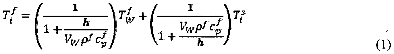
Where 7 is the temperature of fluid cell i, T is the temperature of the fluid cell to the west of fluid cell i, T? is the temperature of solid cell i, VN, VE, and Vw are the known flow velocities across cell boundaries to the North, East, and West respectively, h is the heat transfer coefficient, pf is the density of the fluid, and c/ is the specific heat of the fluid.
Equation (1) has also been simplified to reflect the fact that, for this simple example, VN + VE = Vw. The heat transfer coefficient h is defined by Newton's Law of Cooling: <?"' = TS - f (2) where q is the heat transfer per unit area (for example, in W/m2) and 7* and ^ are the solid and fluid temperatures, respectively. The heat transfer coefficient depends on the flow pattern near the surface as well as the physical properties of the fluid and has been extensively correlated against experimental measurements for simple configurations like that of uniform flow past a flat plate. Correlations for a flat plate configuration are:
1 1
Nu = 0.664 RetPr if Re < 5x10s
if Re≥ 5x10*
(3) where,
 Nusselt Number, a dimensionless form of the heat transfer coefficient
pVL
Re =
Reynolds Number, a dimensionless number which determines flow regime
 = Prandtl Number, a dimensionless number summarizing certain physical properties of the fluid
L - characteristic length scale
k = thermal conductivity of the fluid
V - characteristic flow velocity
μ = viscosity of fluid
In the derivation of Equation ( 1 ) above, a standard "upwind" model was utilized which assumes that energy is conducted into or out of the grid cell only in the direction of the flow. This equation also neglects conduction heat transfer in the fluid as convection (i.e., energy transfer to the bulk movement of fluid) is usually dominant. In other embodiments, these terms could be included in the analysis and terms for the temperatures of all neighboring cells would appear in Equation (1).
Energy transfer through the faces of the solid grid cell of FIG. 3 is due purely to conduction except for the top face where there is convection heat transfer with the fluid. A steady-state energy balance on the solid cell yields an equation for the temperature of the solid cell :
 where Tw s, TE S, and Ts s are the solid temperatures of cells to the West, East, and South respectively and h is the thermal conductivity of the solid.
For a steady-state application, equations similar to Equations (1 ) and (4) may be written for all grid cells. The exact form of the equations may vary depending on the location of the cell which defines the conditions on each face of the cell. For example, for fluid or solid cells completely surrounded by other cells of their same type, there is no fluid-solid
interface and the equations will not contain the heat transfer coefficient, h. The equations may be solved using any one of a variety of techniques, for example, Gauss-Seidel iteration, and the solution may sweep through all solid and fluid cells at each iteration or many iterations may be performed separately in the fluid and the solid before returning to the other region. Some iteration back and forth between fluid and solid may be required as the temperature of the boundary cells affects the temperature in the other region. The coupling of the fluid and solid temperatures is facilitated by the heat transfer coefficient h. The heat transfer coefficient is determined from either experimental correlations or empirical correlations determined from CFD analyses performed "offline" and the h may be based, in part, on the local fluid flow velocities as determined in the PFM analysis.
A flow chart of the steady-state solution process is shown in FIG. 4, indicated generally at 400. After reading all data related to the configuration of the data center (act 410), a computational grid is defined (act 420), and the fluid flow pattern, i.e., the velocity at each cell face, is determined from a PFM analysis (act 430). Next the temperature distributions in the fluid and solid cells are determined sequentially (acts 440 - 460). The process continues until residual error (imbalance of energy flows over all cells) is considered to be smaller than a threshold (act 470), for example, 0.5% of all of the power dissipated in the system being analyzed. Results may then be output to a user (act 480). Transient Applications
In the transient scenario, the fluid flow may be modeled as a series of steady-state flow patterns, where the number of flow patterns predicted depends upon the scenario being analyzed. The scenario may include a thermal disruption; an event where heat produced from a source of heat is either increased or decreased, including events when the source of heat is enabled or disabled, or an event where a cooling provider becomes more or less capable of removing heat from a system, including events where the cooling provider becomes enabled or disabled. Consider, for example, a scenario in which a desktop computer is operating normally, then, at some reference time t=0, one of two cooling fans fails. If it is desired to determine component temperatures at times following t=0, at least two airflow patterns should be determined: the initial airflow pattern with both fans running and the later airflow pattern when only one fan is running.
An equation for the temperature of fluid cell i of FIG. 3 including the transient heating or cooling of the fluid contained in the grid cell is derived as follows. The transient term can be represented as:
the rate of change of stored energy
An energy balance including the transient heating or cooling of solid cell i of FIG. 3 leads to:
 where T'+ is the temperature of solid cell i after a time step of At.
Equations (6) and (7) are "explicit" representations of the temperature in the fluid and solid cells respectively at a future time. Therefore, with this approach, the temperature over all cells can be computed sequentially for a given time step. Then, these temperatures are used on the right-hand side of Equations (6) and (7) to compute temperatures at the next time step. This process continues until the desired transient period has been covered. In some embodiments, in Equation (5), the temperatures of all neighboring cells at the current time are evaluated.
In some embodiments it is also possible to represent the temperatures of all neighboring cells also at the future time. This is referred to herein as an "implicit" approach because the temperature at cell /' cannot be isolated and in Equations (6) and (7), all neighboring-cell temperatures would be denoted with a "+"superscript and become unknowns. With the implicit approach, in some embodiments, all Τ(+ and Τ?+ values over all cells could be determined simultaneously using a solver, for example, Gauss-Seidel iteration, to determine temperatures at each time step. The explicit approach has the advantage of great simplicity; however, it only converges to a sensible result if sufficiently small time steps are
used. The implicit method has the advantage that it will converge regardless of time-step size and therefore, since larger time steps can be used, the total solution time may be less.
The steps in an embodiment of the CPFM for transient applications is shown in a flowchart, indicated generally at 500 in FIG. 5. In this method, acts 510, 520, and 530 are similar to acts 410, 420, and 430 of flowchart 400. Act 510 includes an additional act of determining a number of time periods over which to perform the transient analysis. A greater number of shorter time periods may provide more accurate results than a lesser number of longer time periods. Acts 560, 570, 580, 590, and 600 of flowchart 500 are similar to acts 440, 450, 460, 470, and 480, respectively of flowchart 400. Flowchart 500 includes a decision act 540 where it is determined whether an event causes the airflow Boundary
Conditions (BCs) to change. If so, the altered fluid flows are calculated in act 550 before proceeding to calculate the new fluid and solid temperatures for the associated time period. Acts 540 - 600 are repeated for each time period. In some embodiments, the results may be output (act 600) after the completion of the analysis for all time periods.
With the transient process, airflow patterns, and subsequently temperatures, may have to be recomputed several times depending on the number of transient events. If a transient event causes the airflow BCs to change, for example, a fan is shut off, then airflow patterns may be recalculated; however, if the transient event is limited to a power or temperature change, for example, a component starts dissipating additional heat, then only temperatures need be recalculated.
Example
Consider the 2D steady-state airflow over a heated solid block as shown in FIG. 6. For purposes of distributing the 30W dissipated by the block, the entire system is assumed to be 150 mm deep in the direction into the paper. This configuration could represent, for example, an electronics-thermal application where the primary goal is to determine the temperature of the heated solid block, which could represent a printed circuit board covered with heat-dissipating components. In this simple example, the block is uniformly heated and has a fairly high thermal conductivity so that, in equilibrium, all parts of the block will largely attain a single uniform temperature. In addition to predicting the block temperature, it is desired to also predict the airflow pattern surrounding the block and the temperature of the air everywhere within the enclosure.
The calculation of velocities and temperatures in the fluid follows the PFM approach described in, for example, the '605 application. To couple the solid-conduction and fluid-
convection solutions, it is desirable to accurately predict heat transfer at the fluid-solid boundary.
With the conjugate PFM (CPFM) approach, heat transfer at the fluid-solid boundary may be empirically computed. It is generally not necessary to predict the shape of the velocity or temperature profile close to the wall to a high level of detail. Instead, a heat transfer coefficient, h (for example, in units of W/(m2 °C)), may be utilized to determine the heat transfer as a function of fluid velocities and temperatures near the boundary.
FIG. 7 shows a comparison of the airflow and temperatures from CFD and CPFM calculation methods for the Example of FIG. 6. In this example, the heat transfer coefficients for CPFM were taken from the CFD model. Although this virtually guarantees similar block temperature estimates, in theory, a very good library of hs can be compiled from CFD runs • performed "offline."
Advantages of Conjugate PFM (CPFM)
The advantages of CPFM over CFD are similar to those of PFM over CFD as the time and effort of the problem is dominated by the airflow-solution portion not the conduction- solution portion. The advantages are related to speed, reliability, and simplicity of the model relative to CFD. The high-reliability of the method (i.e., it produces a reasonable result most or all of the time unlike CFD which frequently fails to converge) means that non-physical aspects of the numerical modeling like computational grid and convergence parameters may be hidden from the user. Consequently, such tools can be used by less sophisticated users with less training and support than full CFD and be made available more economically. CPFM tools can be used to analyze problems in seconds or minutes that take hours or days to solve in CFD.
The approach to handling turbulence in CFD and CPFM are markedly different. In
CFD this may be handled in one of two ways: in laminar flow, the user has to be responsible to define enough computational grid cells so that the steep temperature gradient just on the fluid side of the interface is sufficiently resolved. This often requires grid cells on the order of 1 mm or smaller in the direction perpendicular to the solid surface and predictions are slow and highly grid dependent. When turbulence is selected by a CFD software user, a "wall function" may be employed. A wall function is an empirical expression for the shapes of the velocity and temperature profiles just on the fluid side of the interface. Because of the empiricism, the simulation is much less grid dependent and larger cells can be used to yield reasonable results. Unfortunately, CFD generally does not do a good job at handling regions
in "transition," i.e., somewhere in the awkward state between fully laminar and fully turbulent flow and the quality of results are very CFD-code and application dependent and the user needs to decide a priori as to whether the flow is laminar or turbulent.
Since CPFM utilizes prescribed heat transfer coefficients to model heat transfer at fluid-solid boundaries the user never needs to decide if the flow is laminar or turbulent; this decision is made in the CPFM analysis automatically when the proper heat transfer coefficient is selected based on local flow conditions. Although CPFM is not nearly as sensitive to grid size as CFD, the issue of grid size in CPFM is largely irrelevant to the user. In some embodiments, an algorithm may generate a computational grid without any involvement with or even knowledge of the user.
As a result of the tremendous increase in simplicity and solution speed, CPFM tools can quickly analyze multiple design configurations and include optimization features that would be otherwise prohibitively slow in CFD based tools.
In embodiments above, processes and systems are provided that can determine relevant temperatures and air flows in electronic system in steady state conditions. The processes and systems may also determine changes in airflows and temperatures in an electronics system which may occur following a cooling system event which includes a change in heat produced (either an increase or decrease) by one or more components of the electronics system, or an initiation or disruption in operations of part or all of a cooling system. The systems and methods can be used to provide optimized design of electronics systems and other applications. As readily understood by one of ordinary skill in the art, in at least some embodiments, the air flow and/or temperature values determined are predictions for actual values that will occur for systems having the parameters modeled. In methods of at least one embodiment of the invention, after successful modeling of a cluster in a data center, the results of the model may be used as part of a system to order equipment, ship equipment and install equipment in a data center as per the designed layout.
In at least some embodiments of the invention discussed herein, the performance of assessments and calculations in real-time refers to processes that are completed in a matter of a few seconds or less rather than several minutes or longer as can happen with complex calculations, such as those involving typical CFD calculations.
In at least some embodiments described above, the design of an electronics system and/or actual parameters in an electronics system are altered based on predicted air flow. For example, a user of the design and management system may change the location of components and/or cooling apparatus that are used in the actual layout of equipment or the
proposed layout of equipment in the electronics system. These alterations may be implemented to improve the cooling performance and/or may be implemented to provide cost and/or power savings when the performance is found to be within predetermined
specifications. Further, based on determined airflow values, a data management system in accordance with one embodiment, may control one or more CRACs in a data center to adjust the airflow, and in addition, one or more equipment racks can be controlled to reduce power if the airflow is not adequate to provide sufficient cooling.
In at least some embodiments described above, tools and processes are provided for determining airflow in electronics systems. In other embodiments, the tools and processes may be used for other types of systems, for example, in mobile applications, including mobile data centers.
Having thus described several aspects of at least one embodiment of this invention, it is to be appreciated various alterations, modifications, and improvements will readily occur to those skilled in the art. Such alterations, modifications, and improvements are intended to be part of this disclosure, and are intended to be within the spirit and scope of the invention. Accordingly, the foregoing description and drawings are by way of example only.
What is claimed is:
Claims
1. A computer-implemented method for evaluating cooling performance of an electronics system, the system including a plurality of physical components and at least one cooling provider, the method comprising:
receiving information related to physical structures of the electronics system;
dividing the electronics system into a computational grid including a plurality of fluid cells and a plurality of solid cells, positions of the plurality of solid cells corresponding to positions of the physical components within the electronics system;
determining air flow values for the plurality of fluid cells using a potential flow model analysis;
for each fluid cell of the plurality of fluid cells, determining a temperature of the fluid cell by calculating heat transfer into the fluid cell from any adjacent fluid cells and from any adjacent solid cells;
for each solid cell of the plurality of solid cells, determining a temperature of the solid cell by calculating heat transfer into the solid cell from any adjacent solid cells and heat transfer out of the solid cell into any adjacent fluid cells; and
storing, on a storage device, the air flow values and the temperature of the fluid cell and the temperature of the solid cell.
2. The computer implemented method of claim 1, wherein determining one of the temperature of the fluid cell and the temperature of the solid cell includes using a heat transfer coefficient characterizing heat transfer from the solid cell to the liquid cell, wherein the heat transfer coefficient is derived from one of experimental results and previously conducted CFD analyses.
3. The computer implemented method of claim 2, wherein each of the plurality of fluid cells is a three-dimensional cell.
4. The computer implemented method of claim 3, wherein each of the plurality of solid cells is either a one dimensional cell or a two dimensional cell.
5. The computer implemented method of claim 2, wherein the determination of the temperature of each of the plurality of fluid cells and the determination of the temperature of each of the plurality of solid cells is performed for a plurality of contiguous time periods.
6. The computer implemented method of claim 5, further comprising modeling an effect of a thermal disruption in the electronics system during a time period subsequent to the thermal disruption on the temperature of at least a portion of the plurality of solid cells.
7. The computer implemented method of claim 6, further comprising determining modified air flow values which are maintained in the plurality of fluid cells throughout the time period subsequent to the thermal disruption.
8. The computer implemented method of claim 2, further comprising modifying a configuration of the physical structures of the electronics system based on one of the air flow values, the temperature of the fluid cell and the temperature of the solid cell.
9. A system for evaluating equipment in an electronics system, the equipment including a plurality of cooling consumers, and at least one cooling provider, the system comprising:
an interface; and
a controller coupled to the interface and configured to:
receive information related to physical structures of the electronics system; divide the electronics system into a computational grid including a plurality of fluid cells and a plurality of solid cells, positions of the plurality of solid cells corresponding to positions of the physical components within the electronics system; determine air flow values for the plurality of fluid cells using a potential flow model analysis;
for each fluid cell of the plurality of fluid cells, determine a temperature of the fluid cell by calculating heat transfer into the fluid cell from any adjacent fluid cells and from any adjacent solid cells;
for each solid cell of the plurality of solid cells, determine a temperature of the solid cell by calculating heat transfer into the solid cell from any adjacent solid cells and heat transfer out of the solid cell into any adjacent fluid cells; and store, on a storage device, the air flow values and the temperature of the fluid cell and the temperature of the solid cell.
10. The system of claim 9, wherein the controller is configured to determine one of the temperature of the fluid cell and the temperature of the solid cell using a heat transfer coefficient characterizing heat transfer from the solid cell to the liquid cell, wherein the heat transfer coefficient is derived from one of experimental results and previously conducted CFD analyses.
11. The system of claim 10, wherein the controller is configured to determine the temperature of each of the plurality of fluid cells and to determine the temperature of each of the plurality of solid cells for a plurality of contiguous time periods.
12. The system of claim 11, wherein the controller is further configured to model an effect of a thermal disruption in the electronics system during a time period subsequent to the thermal disruption on the temperature of at least a portion of the plurality of solid cells.
13. The system of claim 12, wherein the controller is further configured to model the effect of the thermal disruption on the temperature of at least a portion of the plurality of fluid cells.
14. The system of claim 10, wherein the interface is configured to provide for a user to modify a configuration of the physical structures of the electronics system.
15. A computer readable medium having stored thereon sequences of instruction including instructions that will cause a processor to:
receive information related to physical structures of the electronics system;
divide the electronics system into a computational grid including a plurality of fluid cells and a plurality of solid cells, positions of the plurality of solid cells corresponding to positions of the physical components within the electronics system;
determine air flow values for the plurality of fluid cells using a potential flow model analysis; for each fluid cell of the plurality of fluid cells, determine a temperature of the fluid cell by calculating heat transfer into the fluid cell from any adjacent fluid cells and from any adjacent solid cells;
for each solid cell of the plurality of solid cells, determine a temperature of the solid cell by calculating heat transfer into the solid cell from any adjacent solid cells and heat transfer out of the solid cell into any adjacent fluid cells; and
store, on a storage device, the air flow values and the temperature of the fluid cell and the temperature of the solid cell.
16. The computer readable medium of claim 15, wherein the instructions will cause the processor to determine one of the temperature of the fluid cell and the temperature of the solid cell using a heat transfer coefficient characterizing heat transfer from the solid cell to the liquid cell, wherein the heat transfer coefficient is derived from one of
experimental results and previously conducted CFD analyses.
17. The computer readable medium of claim 16, wherein the instructions will cause the processor to determine the temperature of each of the plurality of fluid cells and to determine the temperature of each of the plurality of solid cells for a plurality of contiguous time periods.
18. The computer readable medium of claim 17, wherein the instructions will further cause the processor to model an effect of a thermal disruption in the electronics system during a time period subsequent to the thermal disruption on the temperature of at least a portion of the plurality of solid cells.
19. The computer readable medium of claim 18, wherein the instructions will further cause the processor to model the effect of the thermal disruption on the temperature of at least a portion of the plurality of fluid cells.
20. The computer readable medium of claim 15, wherein the instructions will cause the processor to modify a model of a configuration of the physical structures of the electronics system based on one of the air flow values, the temperature of the fluid cell and the temperature of the solid cell.
Priority Applications (7)
| Application Number | Priority Date | Filing Date | Title |
|---|---|---|---|
| US14/366,500 US9830410B2 (en) | 2011-12-22 | 2011-12-22 | System and method for prediction of temperature values in an electronics system |
| CN201180076408.1A CN104137660B (en) | 2011-12-22 | 2011-12-22 | System and method for the predicting temperature values in electronic system |
| PCT/US2011/066776 WO2013095494A1 (en) | 2011-12-22 | 2011-12-22 | System and method for prediction of temperature values in an electronics system |
| AU2011383606A AU2011383606A1 (en) | 2011-12-22 | 2011-12-22 | System and method for prediction of temperature values in an electronics system |
| EP11878000.6A EP2796025A4 (en) | 2011-12-22 | 2011-12-22 | System and method for prediction of temperature values in an electronics system |
| IN5663DEN2014 IN2014DN05663A (en) | 2011-12-22 | 2014-07-08 | |
| AU2017202272A AU2017202272A1 (en) | 2011-12-22 | 2017-04-06 | System And Method For Prediction Of Temperature Values In An Electronics System |
Applications Claiming Priority (1)
| Application Number | Priority Date | Filing Date | Title |
|---|---|---|---|
| PCT/US2011/066776 WO2013095494A1 (en) | 2011-12-22 | 2011-12-22 | System and method for prediction of temperature values in an electronics system |
Publications (1)
| Publication Number | Publication Date |
|---|---|
| WO2013095494A1 true WO2013095494A1 (en) | 2013-06-27 |
Family
ID=48669136
Family Applications (1)
| Application Number | Title | Priority Date | Filing Date |
|---|---|---|---|
| PCT/US2011/066776 WO2013095494A1 (en) | 2011-12-22 | 2011-12-22 | System and method for prediction of temperature values in an electronics system |
Country Status (6)
| Country | Link |
|---|---|
| US (1) | US9830410B2 (en) |
| EP (1) | EP2796025A4 (en) |
| CN (1) | CN104137660B (en) |
| AU (2) | AU2011383606A1 (en) |
| IN (1) | IN2014DN05663A (en) |
| WO (1) | WO2013095494A1 (en) |
Cited By (10)
| Publication number | Priority date | Publication date | Assignee | Title |
|---|---|---|---|---|
| EP3091455A3 (en) * | 2015-05-07 | 2016-11-16 | Airbus Group India Private Limited | Thermal analysis of electronics racks |
| EP3079087A3 (en) * | 2015-03-31 | 2016-12-28 | NGK Insulators, Ltd. | Method for analyzing honeycomb structure, and program and analysis device for the same |
| US9830410B2 (en) | 2011-12-22 | 2017-11-28 | Schneider Electric It Corporation | System and method for prediction of temperature values in an electronics system |
| US9952103B2 (en) | 2011-12-22 | 2018-04-24 | Schneider Electric It Corporation | Analysis of effect of transient events on temperature in a data center |
| US10001761B2 (en) | 2014-12-30 | 2018-06-19 | Schneider Electric It Corporation | Power consumption model for cooling equipment |
| US10025330B2 (en) | 2012-09-21 | 2018-07-17 | Schneider Electric It Corporation | Method and apparatus for characterizing thermal transient performance |
| US10210288B2 (en) | 2012-12-27 | 2019-02-19 | Schneider Electric It Corporation | Systems and methods of visualizing airflow |
| CN113158595A (en) * | 2021-04-23 | 2021-07-23 | 重庆中国三峡博物馆 | Method for constructing three-dimensional transient temperature field model inside museum cultural relic showcase |
| US11076507B2 (en) | 2007-05-15 | 2021-07-27 | Schneider Electric It Corporation | Methods and systems for managing facility power and cooling |
| US11419247B2 (en) * | 2020-03-25 | 2022-08-16 | Kyndryl, Inc. | Controlling a working condition of electronic devices |
Families Citing this family (8)
| Publication number | Priority date | Publication date | Assignee | Title |
|---|---|---|---|---|
| US9529641B2 (en) * | 2013-08-26 | 2016-12-27 | Cisco Technology, Inc. | Data center thermal model |
| US10034417B2 (en) * | 2015-02-09 | 2018-07-24 | Schneider Electric It Corporation | System and methods for simulation-based optimization of data center cooling equipment |
| US10617038B2 (en) * | 2016-07-08 | 2020-04-07 | Schneider Electric It Corporation | Zero-equation turbulence models for large electrical and electronics enclosure applications |
| US11076509B2 (en) | 2017-01-24 | 2021-07-27 | The Research Foundation for the State University | Control systems and prediction methods for it cooling performance in containment |
| US10817033B2 (en) * | 2017-12-14 | 2020-10-27 | Schneider Electric It Corporation | Method and system for predicting effect of a transient event on a data center |
| US11582887B2 (en) | 2018-07-17 | 2023-02-14 | Schneider Electric It Corporation | Methods of balancing airflow in ceiling-ducted containment systems |
| EP3889820A1 (en) * | 2020-03-31 | 2021-10-06 | Schneider Electric IT Corporation | Systems and methods for determining liquid cooled architectures in an it room |
| CN112800687B (en) * | 2021-04-06 | 2021-06-22 | 联想长风科技(北京)有限公司 | Method and system for evaluating product heat dissipation scheme |
Citations (3)
| Publication number | Priority date | Publication date | Assignee | Title |
|---|---|---|---|---|
| US7596476B2 (en) * | 2005-05-02 | 2009-09-29 | American Power Conversion Corporation | Methods and systems for managing facility power and cooling |
| US20090326879A1 (en) * | 2008-06-26 | 2009-12-31 | International Business Machines Corporation | Techniques for Thermal Modeling of Data Centers to Improve Energy Efficiency |
| US7991592B2 (en) * | 2007-01-24 | 2011-08-02 | American Power Conversion Corporation | System and method for evaluating equipment rack cooling performance |
Family Cites Families (490)
| Publication number | Priority date | Publication date | Assignee | Title |
|---|---|---|---|---|
| US1025243A (en) | 1912-02-24 | 1912-05-07 | Lewis A Carpenter | Pipe-hanger. |
| US1941258A (en) | 1931-08-14 | 1933-12-26 | Superheater Co Ltd | Interlocking hanger |
| US2455022A (en) | 1944-08-08 | 1948-11-30 | Benjamin F Schmidt | Submersible double-acting fluid piston deep well pump |
| US3317798A (en) | 1966-04-13 | 1967-05-02 | Ibm | Cooling electrical apparatus |
| US3559728A (en) | 1968-11-29 | 1971-02-02 | Kooltronic Fan Co | Electronic equipment rack temperature control |
| US3643007A (en) | 1969-04-02 | 1972-02-15 | Superior Continental Corp | Coaxial cable |
| US3681936A (en) | 1970-10-26 | 1972-08-08 | Oklahoma Mfg Co | Heat exchanger |
| US3742725A (en) | 1971-12-06 | 1973-07-03 | Carrier Corp | Air conditioning unit |
| US3995446A (en) | 1975-07-14 | 1976-12-07 | Eubank Marcus P | Reverse air cycle air conditioner |
| US4055053A (en) | 1975-12-08 | 1977-10-25 | Elfving Thore M | Thermoelectric water cooler or ice freezer |
| US4127008A (en) | 1976-11-01 | 1978-11-28 | Lewis Tyree Jr | Method and apparatus for cooling material using liquid CO2 |
| US4197716A (en) | 1977-09-14 | 1980-04-15 | Halstead Industries, Inc. | Refrigeration system with auxiliary heat exchanger for supplying heat during defrost cycle and for subcooling the refrigerant during a refrigeration cycle |
| US4223535A (en) | 1978-12-22 | 1980-09-23 | Kumm Emerson L | Absorption solar powered air conditioning system with storage capacity |
| US4285205A (en) | 1979-12-20 | 1981-08-25 | Martin Leonard I | Refrigerant sub-cooling |
| US4275570A (en) | 1980-06-16 | 1981-06-30 | Vilter Manufacturing Corporation | Oil cooling means for refrigeration screw compressor |
| US4419865A (en) | 1981-12-31 | 1983-12-13 | Vilter Manufacturing Company | Oil cooling apparatus for refrigeration screw compressor |
| US4590538A (en) | 1982-11-18 | 1986-05-20 | Cray Research, Inc. | Immersion cooled high density electronic assembly |
| US4747041A (en) | 1983-06-27 | 1988-05-24 | Unisys Corporation | Automatic power control system which automatically activates and deactivates power to selected peripheral devices based upon system requirement |
| US4515746A (en) | 1983-09-06 | 1985-05-07 | General Electric Company | Microcomposite of metal carbide and ceramic particles |
| US4564767A (en) | 1983-11-07 | 1986-01-14 | Tii Industries, Inc. | Uninterruptible switching power supply system |
| US4599873A (en) | 1984-01-31 | 1986-07-15 | Hyde Robert E | Apparatus for maximizing refrigeration capacity |
| US4718249A (en) | 1984-04-16 | 1988-01-12 | Hanson Wallace G | Apparatus for heating and cooling |
| JPH0685471B1 (en) | 1984-11-15 | 1994-10-26 | Fujitsu Ltd | |
| US4673826A (en) | 1984-12-20 | 1987-06-16 | The United States Of America As Represented By The Secretary Of The Air Force | Autonomous uninterruptable power supply apparatus |
| US4696168A (en) | 1986-10-01 | 1987-09-29 | Roger Rasbach | Refrigerant subcooler for air conditioning systems |
| US4683529A (en) | 1986-11-12 | 1987-07-28 | Zytec Corporation | Switching power supply with automatic power factor correction |
| JPS63127042A (en) | 1986-11-17 | 1988-05-30 | Sanki Eng Co Ltd | Heat storage type air conditioning system |
| JPH0770853B2 (en) | 1987-01-21 | 1995-07-31 | 株式会社日立製作所 | Electronic device cooling system |
| US5168724A (en) | 1987-02-06 | 1992-12-08 | Reaction Thermal Systems, Inc. | Ice building, chilled water system |
| CN1012244B (en) | 1987-02-20 | 1991-03-27 | 株式会社东芝 | Uninterruptible power source equipment |
| FR2614748A1 (en) | 1987-04-29 | 1988-11-04 | Omega Electronics Sa | DEVICE FOR SUPPLYING A DISCHARGE LAMP |
| JPH0813171B2 (en) | 1987-06-26 | 1996-02-07 | 株式会社ユタカ電機製作所 | Stabilized power supply |
| US4823290A (en) | 1987-07-21 | 1989-04-18 | Honeywell Bull Inc. | Method and apparatus for monitoring the operating environment of a computer system |
| GB8724263D0 (en) | 1987-10-15 | 1987-11-18 | Bicc Plc | Electronic enclosure cooling system |
| US4827733A (en) | 1987-10-20 | 1989-05-09 | Dinh Company Inc. | Indirect evaporative cooling system |
| US4831508A (en) | 1987-10-20 | 1989-05-16 | Computer Products Inc. | Power supply system having improved input power factor |
| US4816982A (en) | 1987-11-23 | 1989-03-28 | Viteq Corporation | AC to DC power converter with integrated line current control for improving power factor |
| FR2624684B1 (en) | 1987-12-11 | 1990-05-04 | Spie Batignolles | METHOD AND DEVICE FOR COOLING ELECTRICAL PANELS |
| JPH01218918A (en) | 1988-02-26 | 1989-09-01 | Sanden Corp | Air conditioner for vehicle |
| US4964029A (en) | 1988-05-18 | 1990-10-16 | Viteq Corporation | AC to DC power converter with input current waveform control for buck-boost regulation of output |
| WO1990002379A1 (en) | 1988-08-23 | 1990-03-08 | Derek Robert Marsden | Utility metering |
| US5173819A (en) | 1988-10-05 | 1992-12-22 | Hitachi, Ltd. | Disk apparatus having an improved cooling structure |
| US5184025A (en) | 1988-11-14 | 1993-02-02 | Elegant Design Solutions, Inc. | Computer-controlled uninterruptible power supply |
| US5019717A (en) | 1988-11-14 | 1991-05-28 | Elegant Design Solutions Inc. | Computer-controlled uninterruptable power supply |
| FR2646579A1 (en) | 1989-03-20 | 1990-11-02 | Guillemot Gerard | ELECTRICALLY HIGH TEMPERATURE HEATING EQUIPMENT BY REGULATED AREAS FOR THE USE OF COMPOSITE MATERIAL PRODUCTS |
| US5195706A (en) | 1989-03-27 | 1993-03-23 | Allen William M | Device for holding a container upright |
| US5017800A (en) | 1989-09-29 | 1991-05-21 | Wisconsin Alumni Research Foundation | AC to DC to AC power conversion apparatus with few active switches and input and output control |
| US5057968A (en) | 1989-10-16 | 1991-10-15 | Lockheed Corporation | Cooling system for electronic modules |
| US4980812A (en) | 1989-11-09 | 1990-12-25 | Exide Electronics | Uninterrupted power supply system having improved power factor correction circuit |
| US4962734A (en) | 1990-03-14 | 1990-10-16 | Paccar Inc. | Electrically driven, circumferentially supported fan |
| US5396635A (en) | 1990-06-01 | 1995-03-07 | Vadem Corporation | Power conservation apparatus having multiple power reduction levels dependent upon the activity of the computer system |
| US5216623A (en) | 1990-06-06 | 1993-06-01 | M. T. Mcbrian, Inc. | System and method for monitoring and analyzing energy characteristics |
| US5126585A (en) | 1990-06-19 | 1992-06-30 | Auckland Uniservices Limited | Uninterruptible power supplies |
| US6105061A (en) | 1990-07-26 | 2000-08-15 | Nec Corporation | Hierarchically distributed network management system using open system interconnection (OSI) protocols |
| US5047913A (en) | 1990-09-17 | 1991-09-10 | General Electric Company | Method for controlling a power converter using an auxiliary resonant commutation circuit |
| US5153837A (en) | 1990-10-09 | 1992-10-06 | Sleuth Inc. | Utility consumption monitoring and control system |
| US5097328A (en) | 1990-10-16 | 1992-03-17 | Boyette Robert B | Apparatus and a method for sensing events from a remote location |
| US5237833A (en) | 1991-01-10 | 1993-08-24 | Mitsubishi Denki Kabushiki Kaisha | Air-conditioning system |
| US5150580A (en) | 1991-03-08 | 1992-09-29 | Hyde Robert E | Liquid pressure amplification with superheat suppression |
| US5095712A (en) | 1991-05-03 | 1992-03-17 | Carrier Corporation | Economizer control with variable capacity |
| US5382943A (en) | 1991-07-31 | 1995-01-17 | Tanaka; Mutuo | Remote monitoring unit |
| CA2071804A1 (en) | 1991-06-24 | 1992-12-25 | Ronald G. Ward | Computer system manager |
| US5177666A (en) | 1991-10-24 | 1993-01-05 | Bland Timothy J | Cooling rack for electronic devices |
| US5234185A (en) | 1992-02-21 | 1993-08-10 | General Motors Corporation | Unitary pipe clamp and assembly |
| US5410448A (en) | 1992-03-02 | 1995-04-25 | Digital Equipment Corporation | Adaptive cooling system |
| US5181653A (en) | 1992-03-03 | 1993-01-26 | Foster Glenn D | Residential heating and air conditioning control system |
| CA2069273A1 (en) | 1992-05-22 | 1993-11-23 | Edward L. Ratcliffe | Energy management systems |
| US5319571A (en) | 1992-11-24 | 1994-06-07 | Exide Electronics | UPS system with improved network communications |
| US5383339A (en) | 1992-12-10 | 1995-01-24 | Baltimore Aircoil Company, Inc. | Supplemental cooling system for coupling to refrigerant-cooled apparatus |
| US5269372A (en) | 1992-12-21 | 1993-12-14 | International Business Machines Corporation | Intersecting flow network for a cold plate cooling system |
| US5649428A (en) | 1993-01-08 | 1997-07-22 | Engelhard/Icc | Hybrid air-conditioning system with improved recovery evaporator and subcool condenser coils |
| US6069412A (en) | 1993-03-29 | 2000-05-30 | Powerware Corporation | Power factor corrected UPS with improved connection of battery to neutral |
| JPH0744275A (en) | 1993-07-30 | 1995-02-14 | Hitachi Ltd | Air cooling type information processor |
| US5972196A (en) | 1995-06-07 | 1999-10-26 | Lynntech, Inc. | Electrochemical production of ozone and hydrogen peroxide |
| US5528507A (en) | 1993-08-11 | 1996-06-18 | First Pacific Networks | System for utility demand monitoring and control using a distribution network |
| US5749237A (en) | 1993-09-28 | 1998-05-12 | Jdm, Ltd. | Refrigerant system flash gas suppressor with variable speed drive |
| US5860012A (en) | 1993-09-30 | 1999-01-12 | Intel Corporation | Installation of application software through a network from a source computer system on to a target computer system |
| FR2713030B1 (en) | 1993-11-24 | 1996-01-12 | Merlin Gerin | Uninterruptible feed through neutral through, comprising a double chopper-elevator. |
| FR2713305B1 (en) | 1993-11-29 | 1996-02-09 | Valeo Thermique Habitacle | Quick coupling device for heat exchanger pipes. |
| US5684686A (en) | 1994-01-12 | 1997-11-04 | Deltec Electronics Corporation | Boost-input backed-up uninterruptible power supply |
| US5462225A (en) | 1994-02-04 | 1995-10-31 | Scientific-Atlanta, Inc. | Apparatus and method for controlling distribution of electrical energy to a space conditioning load |
| JPH07269926A (en) | 1994-02-14 | 1995-10-20 | Daikin Ind Ltd | Control device for air conditioner |
| US5845090A (en) | 1994-02-14 | 1998-12-01 | Platinium Technology, Inc. | System for software distribution in a digital computer network |
| JPH07245955A (en) | 1994-03-02 | 1995-09-19 | Yutaka Denki Seisakusho:Kk | Regulated power supply with improved power factor and uninterruptible power supply |
| US5963457A (en) | 1994-03-18 | 1999-10-05 | Hitachi, Ltd. | Electrical power distribution monitoring system and method |
| US5995729A (en) | 1994-07-22 | 1999-11-30 | Hitachi, Ltd. | Method and apparatus for aiding configurating management of a computer system |
| US5978594A (en) | 1994-09-30 | 1999-11-02 | Bmc Software, Inc. | System for managing computer resources across a distributed computing environment by first reading discovery information about how to determine system resources presence |
| US5582020A (en) | 1994-11-23 | 1996-12-10 | Mainstream Engineering Corporation | Chemical/mechanical system and method using two-phase/two-component compression heat pump |
| US5533357A (en) | 1995-02-15 | 1996-07-09 | Carrier Corporation | Air conditioning apparatus |
| US5602462A (en) | 1995-02-21 | 1997-02-11 | Best Power Technology, Incorporated | Uninterruptible power system |
| US5572873A (en) | 1995-03-02 | 1996-11-12 | Emertech Incorporated | Carrier method and apparatus for maintaining pharmaceutical integrity |
| US5581478A (en) | 1995-04-13 | 1996-12-03 | Cruse; Michael | Facility environmental control system |
| JP3113793B2 (en) | 1995-05-02 | 2000-12-04 | 株式会社エヌ・ティ・ティ ファシリティーズ | Air conditioning system |
| GB2301206A (en) | 1995-05-23 | 1996-11-27 | Compaq Computer Corp | A system for facilitating creation of a computer |
| US6112235A (en) | 1995-06-07 | 2000-08-29 | Spofford; Jason J. | Method and apparatus for remotely managing a network hardware device having an embedded server with a client computer across a network |
| US5704219A (en) | 1995-08-01 | 1998-01-06 | Nippondenso Co., Ltd. | Air conditioning apparatus |
| US6038879A (en) | 1995-08-08 | 2000-03-21 | Yvon Turcotte | Combined air exchange and air conditioning unit |
| US5657641A (en) | 1995-09-13 | 1997-08-19 | Kooltronic, Inc. | Panel mounted cooling system |
| US5970734A (en) | 1995-09-29 | 1999-10-26 | Stillwell; Robert | Method and system for creating and maintaining a frozen surface |
| US6317775B1 (en) | 1995-11-03 | 2001-11-13 | Cisco Technology, Inc. | System for distributing load over multiple servers at an internet site |
| US5694780A (en) | 1995-12-01 | 1997-12-09 | Alsenz; Richard H. | Condensed liquid pump for compressor body cooling |
| US6032472A (en) | 1995-12-06 | 2000-03-07 | Carrier Corporation | Motor cooling in a refrigeration system |
| US5794897A (en) | 1996-04-22 | 1998-08-18 | Andrew Corporation | Transmission line hanger, a method of attaching the hanger and the resulting assembly |
| US6104868A (en) | 1996-04-30 | 2000-08-15 | Peters; Daniel G. | Extendible and portable network protocol based system management architecture |
| JP2776369B2 (en) | 1996-05-08 | 1998-07-16 | 日本電気株式会社 | Electronic device cooling structure |
| US5735134A (en) | 1996-05-30 | 1998-04-07 | Massachusetts Institute Of Technology | Set point optimization in vapor compression cycles |
| US6151643A (en) | 1996-06-07 | 2000-11-21 | Networks Associates, Inc. | Automatic updating of diverse software products on multiple client computer systems by downloading scanning application to client computer and generating software list on client computer |
| US5949974A (en) | 1996-07-23 | 1999-09-07 | Ewing; Carrell W. | System for reading the status and for controlling the power supplies of appliances connected to computer networks |
| WO1998005060A1 (en) | 1996-07-31 | 1998-02-05 | The Board Of Trustees Of The Leland Stanford Junior University | Multizone bake/chill thermal cycling module |
| US6111036A (en) | 1996-10-17 | 2000-08-29 | Eastman Chemical Company | Method for improving cooling of fluid bed polymer reactor |
| US5960204A (en) | 1996-10-28 | 1999-09-28 | J.D. Edwards World Source Company | System and method for installing applications on a computer on an as needed basis |
| JPH10163538A (en) | 1996-12-04 | 1998-06-19 | Ngk Insulators Ltd | Thermoelectric conversion device for heat exchanger |
| US6085243A (en) | 1996-12-13 | 2000-07-04 | 3Com Corporation | Distributed remote management (dRMON) for networks |
| US6108782A (en) | 1996-12-13 | 2000-08-22 | 3Com Corporation | Distributed remote monitoring (dRMON) for networks |
| US5974237A (en) | 1996-12-18 | 1999-10-26 | Northern Telecom Limited | Communications network monitoring |
| FR2758019B1 (en) | 1996-12-30 | 1999-01-22 | Alsthom Cge Alcatel | POWER CONVERTER WITH IMPROVED CONTROL OF MAIN SWITCHES |
| US7216043B2 (en) | 1997-02-12 | 2007-05-08 | Power Measurement Ltd. | Push communications architecture for intelligent electronic devices |
| GB2323433B (en) | 1997-03-18 | 2001-04-18 | Whitlenge Drink Equipment Ltd | Improvements relating to cooling devices |
| US5978912A (en) | 1997-03-20 | 1999-11-02 | Phoenix Technologies Limited | Network enhanced BIOS enabling remote management of a computer without a functioning operating system |
| US5923103A (en) | 1997-03-31 | 1999-07-13 | Pulizzi Engineering, Inc. | Switched-output controller apparatus with repeater function and method for constructing same |
| US6189109B1 (en) | 1997-05-13 | 2001-02-13 | Micron Electronics, Inc. | Method of remote access and control of environmental conditions |
| US6324608B1 (en) | 1997-05-13 | 2001-11-27 | Micron Electronics | Method for hot swapping of network components |
| US5968398A (en) | 1997-05-16 | 1999-10-19 | The Lepel Corporation | Apparatus and method for non-contact detection and inductive heating of heat retentive food server warming plates |
| JPH10332246A (en) | 1997-06-03 | 1998-12-15 | Ke Corp:Kk | Cooling device |
| US5987614A (en) | 1997-06-17 | 1999-11-16 | Vadem | Distributed power management system and method for computer |
| US6389464B1 (en) | 1997-06-27 | 2002-05-14 | Cornet Technology, Inc. | Device management system for managing standards-compliant and non-compliant network elements using standard management protocols and a universal site server which is configurable from remote locations via internet browser technology |
| US5860280A (en) | 1997-07-03 | 1999-01-19 | Marlow Industries, Inc. | Liquid cooling system with solid material formation control and method of manufacture |
| JP3306651B2 (en) | 1997-07-07 | 2002-07-24 | 吉田 富貴子 | Remote power switching equipment |
| US5963425A (en) | 1997-07-16 | 1999-10-05 | International Business Machines Corporation | Combined air and refrigeration cooling for computer systems |
| US5954127A (en) | 1997-07-16 | 1999-09-21 | International Business Machines Corporation | Cold plate for dual refrigeration system |
| US5970731A (en) | 1997-11-21 | 1999-10-26 | International Business Machines Corporation | Modular refrigeration system |
| US6034872A (en) | 1997-07-16 | 2000-03-07 | International Business Machines Corporation | Cooling computer systems |
| US6213194B1 (en) | 1997-07-16 | 2001-04-10 | International Business Machines Corporation | Hybrid cooling system for electronics module |
| US5924486A (en) | 1997-10-29 | 1999-07-20 | Tecom, Inc. | Environmental condition control and energy management system and method |
| US6055480A (en) | 1997-11-12 | 2000-04-25 | Albert Einstein Healthcare Network | Environmental monitoring system |
| US6438978B1 (en) | 1998-01-07 | 2002-08-27 | General Electric Company | Refrigeration system |
| GB2333864B (en) | 1998-01-28 | 2003-05-07 | Ibm | Distribution of software updates via a computer network |
| US7047300B1 (en) | 1998-02-10 | 2006-05-16 | Sprint Communications Company L.P. | Survivable and scalable data system and method for computer networks |
| ES2231937T3 (en) | 1998-02-23 | 2005-05-16 | Mitsubishi Denki Kabushiki Kaisha | AIR CONDITIONER. |
| US6922558B2 (en) | 1998-03-06 | 2005-07-26 | Don Delp | Integrated building control and information system with wireless networking |
| US6088225A (en) | 1998-03-17 | 2000-07-11 | Northern Telecom Limited | Cabinet with enhanced convection cooling |
| US5953930A (en) | 1998-03-31 | 1999-09-21 | International Business Machines Corporation | Evaporator for use in an extended air cooling system for electronic components |
| US6223810B1 (en) | 1998-03-31 | 2001-05-01 | International Business Machines | Extended air cooling with heat loop for dense or compact configurations of electronic components |
| US6134511A (en) | 1998-04-15 | 2000-10-17 | Subbarao; Krishnappa | Method and apparatus for improving building energy simulations |
| US6347627B1 (en) | 1998-04-23 | 2002-02-19 | Pioneer Inventions, Inc. | Nitrous oxide based oxygen supply system |
| CN2337456Y (en) | 1998-05-08 | 1999-09-08 | 肖小松 | Full-closed separating air conditioner |
| US6038877A (en) | 1998-05-22 | 2000-03-21 | Bergstrom, Inc. | Modular low pressure delivery vehicle air conditioning system |
| US6363421B2 (en) | 1998-05-31 | 2002-03-26 | Lucent Technologies, Inc. | Method for computer internet remote management of a telecommunication network element |
| US6115273A (en) | 1998-07-09 | 2000-09-05 | Illinois Tool Works Inc. | Power converter with low loss switching |
| US5982652A (en) | 1998-07-14 | 1999-11-09 | American Power Conversion | Method and apparatus for providing uninterruptible power using a power controller and a redundant power controller |
| US6141762A (en) | 1998-08-03 | 2000-10-31 | Nicol; Christopher J. | Power reduction in a multiprocessor digital signal processor based on processor load |
| JP4195959B2 (en) | 1998-08-07 | 2008-12-17 | パナソニック株式会社 | Uninterruptible power system |
| US6246969B1 (en) | 1998-09-08 | 2001-06-12 | International Business Machines Corporation | Method and apparatus for testing computer cooling systems |
| BR9914641A (en) | 1998-10-20 | 2002-01-29 | Atd Corp | Corrugated multilayer metal bellows insulation panels and manufacturing processes |
| JP3644579B2 (en) | 1998-10-29 | 2005-04-27 | 富士通株式会社 | Security enhancement method and apparatus |
| US6191500B1 (en) | 1998-11-06 | 2001-02-20 | Kling Lindquist Partnership, Inc. | System and method for providing an uninterruptible power supply to a critical load |
| US6631134B1 (en) | 1999-01-15 | 2003-10-07 | Cisco Technology, Inc. | Method for allocating bandwidth in an optical network |
| AU4033100A (en) | 1999-03-29 | 2000-10-16 | Caterpillar Inc. | Modular chilled fluid system and method for providing chilled fluid for cooling |
| US6404658B1 (en) | 1999-05-13 | 2002-06-11 | American Power Conversion | Method and apparatus for converting a DC voltage to an AC voltage |
| JP3589086B2 (en) | 1999-05-17 | 2004-11-17 | 松下電器産業株式会社 | Power supply |
| US6209330B1 (en) | 1999-05-17 | 2001-04-03 | Caterpillar Inc. | Modular air handling system and method for providing cooling |
| US7606760B2 (en) | 1999-06-18 | 2009-10-20 | Echarge Corporation | Method and apparatus for ordering goods, services and content over an internetwork using a virtual payment account |
| US6208510B1 (en) | 1999-07-23 | 2001-03-27 | Teradyne, Inc. | Integrated test cell cooling system |
| US6237353B1 (en) | 1999-07-29 | 2001-05-29 | Carrier Corporation | System for removing parasitic losses in a refrigeration unit |
| US6483730B2 (en) | 1999-08-13 | 2002-11-19 | Powerware Corporation | Power converters with AC and DC operating modes and methods of operation thereof |
| US6281790B1 (en) | 1999-09-01 | 2001-08-28 | Net Talon Security Systems, Inc. | Method and apparatus for remotely monitoring a site |
| GB2354062A (en) | 1999-09-13 | 2001-03-14 | British Broadcasting Corp | Cooling system for use in cooling electronic equipment |
| US7392309B2 (en) | 1999-10-27 | 2008-06-24 | American Power Conversion Corporation | Network appliance management |
| US6714977B1 (en) | 1999-10-27 | 2004-03-30 | Netbotz, Inc. | Method and system for monitoring computer networks and equipment |
| US6327143B1 (en) | 1999-11-05 | 2001-12-04 | Cray, Inc. | Radial computer system and method |
| BR9907351A (en) | 1999-12-22 | 2001-08-07 | Ericsson Telecomunicacoees S A | Control method and circuit for three-level three-level elevator rectifier |
| JP2001184145A (en) | 1999-12-27 | 2001-07-06 | Id Gate Co Ltd | Remote power supply management system for information processor or the like |
| US6814134B1 (en) | 2000-01-24 | 2004-11-09 | Mary E. Brezinski | Compact electronic cabinet cooler |
| US6574970B2 (en) | 2000-02-18 | 2003-06-10 | Toc Technology, Llc | Computer room air flow method and apparatus |
| US6494050B2 (en) | 2000-02-18 | 2002-12-17 | Toc Technology, Llc | Computer rack heat extraction device |
| TW550477B (en) | 2000-03-01 | 2003-09-01 | Passgate Corp | Method, system and computer readable medium for Web site account and e-commerce management from a central location |
| US6792321B2 (en) | 2000-03-02 | 2004-09-14 | Electro Standards Laboratories | Remote web-based control |
| CA2391036C (en) | 2000-03-17 | 2006-02-07 | Sunarc Structures Inc. | Dynamic heating and cooling of a building using liquid foam |
| JP2001260640A (en) | 2000-03-21 | 2001-09-26 | Calsonic Kansei Corp | Heating device for vehicle |
| EP1266548B2 (en) | 2000-03-21 | 2015-07-29 | Liebert Corporation | Method and apparatus for cooling electronic enclosures |
| US20010047387A1 (en) | 2000-03-27 | 2001-11-29 | Exoplex, Inc. | Systems and methods for providing distributed cross-enterprise portals |
| US20040031282A1 (en) | 2000-04-14 | 2004-02-19 | Kopko William Leslie | Desiccant air conditioner |
| US6670810B2 (en) | 2000-04-25 | 2003-12-30 | Airak, Inc. | System and method for distributed monitoring of surroundings using telemetry of data from remote sensors |
| EP1290662B1 (en) | 2000-04-26 | 2016-07-06 | Schneider Electric IT Corporation | System and method for managing uninterruptible power supply systems |
| US6827142B2 (en) | 2000-04-27 | 2004-12-07 | Innoventor Engineering, Inc. | Process and apparatus for achieving precision temperature control |
| US6761212B2 (en) | 2000-05-25 | 2004-07-13 | Liebert Corporation | Spiral copper tube and aluminum fin thermosyphon heat exchanger |
| US7010594B2 (en) | 2000-05-26 | 2006-03-07 | Isochron, Llc | System using environmental sensor and intelligent management and control transceiver for monitoring and controlling remote computing resources |
| US20020023258A1 (en) | 2000-06-27 | 2002-02-21 | Elwahab Amgad Mazen | System and method for managing telecommunications devices |
| US7693976B2 (en) | 2000-07-11 | 2010-04-06 | Ciena Corporation | Granular management of network resources |
| US6633823B2 (en) | 2000-07-13 | 2003-10-14 | Nxegen, Inc. | System and method for monitoring and controlling energy usage |
| JP3766005B2 (en) | 2000-08-09 | 2006-04-12 | 株式会社イトーキ | Moving shelf equipment |
| US6557624B1 (en) | 2000-08-09 | 2003-05-06 | Liebert Corporation | Configurable system and method for cooling a room |
| GB0021393D0 (en) | 2000-08-31 | 2000-10-18 | Imi Cornelius Uk Ltd | Thermoelectric module |
| US7292898B2 (en) | 2000-09-18 | 2007-11-06 | Balboa Instruments, Inc. | Method and apparatus for remotely monitoring and controlling a pool or spa |
| US20040003266A1 (en) | 2000-09-22 | 2004-01-01 | Patchlink Corporation | Non-invasive automatic offsite patch fingerprinting and updating system and method |
| US7032119B2 (en) | 2000-09-27 | 2006-04-18 | Amphus, Inc. | Dynamic power and workload management for multi-server system |
| US7058826B2 (en) | 2000-09-27 | 2006-06-06 | Amphus, Inc. | System, architecture, and method for logical server and other network devices in a dynamically configurable multi-server network environment |
| US7228441B2 (en) | 2000-09-27 | 2007-06-05 | Huron Ip Llc | Multi-server and multi-CPU power management system and method |
| JP4013470B2 (en) | 2000-09-29 | 2007-11-28 | 株式会社イトーキ | Manual moving shelf device |
| US6917124B2 (en) | 2000-10-27 | 2005-07-12 | Liebert Corporation | Uninterruptible power supply |
| US6330176B1 (en) | 2000-11-15 | 2001-12-11 | Powerware Corporation | Multi-input power transfer and uninterruptible power supply apparatus and methods of operation thereof |
| US6829630B1 (en) | 2000-11-24 | 2004-12-07 | Xerox Corporation | Mechanisms for web-object event/state-driven communication between networked devices |
| JP2002168551A (en) | 2000-11-30 | 2002-06-14 | Tokyo Electron Ltd | Cooling device for electrode of treating device |
| US20020071031A1 (en) | 2000-12-07 | 2002-06-13 | Philips Electronics North America Corporation | Remote monitoring via a consumer electronic appliance |
| US6459579B1 (en) | 2001-01-03 | 2002-10-01 | Juniper Networks, Inc. | Apparatus and method for directing airflow in three dimensions to cool system components |
| US6374627B1 (en) | 2001-01-09 | 2002-04-23 | Donald J. Schumacher | Data center cooling system |
| WO2002060124A2 (en) | 2001-01-26 | 2002-08-01 | Netbotz, Inc. | Method and system for a set of network appliances which can be connected to provide enhanced collaboration, scalability, and reliability |
| DK174494B1 (en) | 2001-01-26 | 2003-04-22 | American Power Conversion Denm | Combined AC-DC to DC converter |
| US6766008B2 (en) | 2001-01-31 | 2004-07-20 | Nhc Communications | System and method for switching telecommunications service in a multiple dwelling unit/multiple tenant unit environment |
| US7975156B2 (en) | 2008-10-21 | 2011-07-05 | Dell Products, Lp | System and method for adapting a power usage of a server during a data center cooling failure |
| US6539725B2 (en) | 2001-02-09 | 2003-04-01 | Bsst Llc | Efficiency thermoelectrics utilizing thermal isolation |
| US7493391B2 (en) | 2001-02-12 | 2009-02-17 | International Business Machines Corporation | System for automated session resource clean-up by determining whether server resources have been held by client longer than preset thresholds |
| US6682100B2 (en) | 2001-02-15 | 2004-01-27 | Parker-Hannifin Corporation | Connection block with clip |
| US20020129355A1 (en) | 2001-03-01 | 2002-09-12 | Mike Velten | Method and system for monitoring an apparatus for a computer |
| AU2002238775B2 (en) | 2001-03-13 | 2006-08-31 | Applied Design And Engineering Limited | Use of heat in cold storage appliances |
| US6967283B2 (en) | 2001-03-20 | 2005-11-22 | American Power Conversion Corporation | Adjustable scalable rack power system and method |
| US6992247B2 (en) | 2002-01-02 | 2006-01-31 | American Power Conversion Corporation | Toolless mounting system and method for an adjustable scalable rack power system |
| JP3870048B2 (en) | 2001-03-26 | 2007-01-17 | 三星電子株式会社 | Multi-room refrigerator and control method thereof |
| US20030196126A1 (en) | 2002-04-11 | 2003-10-16 | Fung Henry T. | System, method, and architecture for dynamic server power management and dynamic workload management for multi-server environment |
| US6535382B2 (en) | 2001-04-12 | 2003-03-18 | Johnson Controls Technology Company | Cooling system for electronic equipment cabinets |
| US6424119B1 (en) | 2001-04-19 | 2002-07-23 | American Power Conversion | Multiple energy storage device controller |
| EP1386114B1 (en) | 2001-05-09 | 2007-04-04 | Maersk Container Industri As | Cooling unit and container with this unit |
| US6701725B2 (en) | 2001-05-11 | 2004-03-09 | Field Diagnostic Services, Inc. | Estimating operating parameters of vapor compression cycle equipment |
| US6848989B2 (en) | 2001-05-30 | 2005-02-01 | Kongo Kabushiki Kaisha | Environmental improvement device for a storage body |
| WO2003005200A1 (en) | 2001-07-06 | 2003-01-16 | Computer Associates Think, Inc. | Method and system for correlating and determining root causes of system and enterprise events |
| US6718781B2 (en) | 2001-07-11 | 2004-04-13 | Thermo King Corporation | Refrigeration unit apparatus and method |
| US6415628B1 (en) | 2001-07-25 | 2002-07-09 | Praxair Technology, Inc. | System for providing direct contact refrigeration |
| US7519909B2 (en) | 2001-08-10 | 2009-04-14 | American Power Conversion Corporation | Uninterruptible power supply (UPS) devices monitoring system |
| US20030042004A1 (en) | 2001-08-29 | 2003-03-06 | Shlomo Novotny | Interchangeable cartridges for cooling electronic components |
| US6672955B2 (en) | 2001-09-07 | 2004-01-06 | International Business Machines Corporation | Air flow management system for an internet data center |
| JP3829846B2 (en) | 2001-10-03 | 2006-10-04 | 三菱電機株式会社 | Uninterruptible power system |
| US6474087B1 (en) | 2001-10-03 | 2002-11-05 | Carrier Corporation | Method and apparatus for the control of economizer circuit flow for optimum performance |
| US6574104B2 (en) | 2001-10-05 | 2003-06-03 | Hewlett-Packard Development Company L.P. | Smart cooling of data centers |
| WO2003034523A1 (en) | 2001-10-11 | 2003-04-24 | Hitachi, Ltd. | Home-use fuel cell system |
| US6957353B2 (en) | 2001-10-31 | 2005-10-18 | Hewlett-Packard Development Company, L.P. | System and method for providing minimal power-consuming redundant computing hardware for distributed services |
| US7203846B2 (en) | 2001-10-31 | 2007-04-10 | Hewlett-Packard Development Company, Lp. | System and method for intelligent control of power consumption of distributed services during periods of reduced load |
| US6600298B2 (en) | 2001-10-31 | 2003-07-29 | Dell Products L.P. | Switching DC-DC converter with the output voltage changing inversely to any change in the converter inductor current |
| US7043650B2 (en) | 2001-10-31 | 2006-05-09 | Hewlett-Packard Development Company, L.P. | System and method for intelligent control of power consumption of distributed services during periods when power consumption must be reduced |
| US6804975B2 (en) | 2001-11-30 | 2004-10-19 | Choon-Kyoung Park | Air conditioning apparatus |
| US6804616B2 (en) | 2001-12-13 | 2004-10-12 | Intel Corporation | Method to estimate power and cooling requirements of systems |
| US7020586B2 (en) | 2001-12-17 | 2006-03-28 | Sun Microsystems, Inc. | Designing a data center |
| US7310673B2 (en) | 2001-12-21 | 2007-12-18 | Hewlett-Packard Development Company, L.P. | Network resource assignment system and method |
| US6721672B2 (en) | 2002-01-02 | 2004-04-13 | American Power Conversion | Method and apparatus for preventing overloads of power distribution networks |
| US7519000B2 (en) | 2002-01-30 | 2009-04-14 | Panduit Corp. | Systems and methods for managing a network |
| US7024573B2 (en) | 2002-02-05 | 2006-04-04 | Hewlett-Packard Development Company, L.P. | Method and apparatus for cooling heat generating components |
| US20030149608A1 (en) | 2002-02-06 | 2003-08-07 | Kall Jonathan J. | Suite of configurable supply chain infrastructure modules for deploying collaborative e-manufacturing solutions |
| US6628520B2 (en) | 2002-02-06 | 2003-09-30 | Hewlett-Packard Development Company, L.P. | Method, apparatus, and system for cooling electronic components |
| US20030154285A1 (en) | 2002-02-13 | 2003-08-14 | International Business Machines Corporation | Method and system for assigning network addreses |
| US7313503B2 (en) * | 2002-02-19 | 2007-12-25 | Hewlett-Packard Development Company, L.P. | Designing layout for internet datacenter cooling |
| US6640889B1 (en) | 2002-03-04 | 2003-11-04 | Visteon Global Technologies, Inc. | Dual loop heat and air conditioning system |
| US6964539B2 (en) | 2002-03-18 | 2005-11-15 | International Business Machines Corporation | Method for managing power consumption of multiple computer servers |
| US6795928B2 (en) | 2002-03-18 | 2004-09-21 | International Business Machines Corporation | Method for managing power consumption of multiple computer servers |
| KR100387358B1 (en) | 2002-03-22 | 2003-06-12 | Ec Tech Co Ltd | System for cooling computer component using thermoelectric element |
| GB0207382D0 (en) | 2002-03-28 | 2002-05-08 | Holland Heating Uk Ltd | Computer cabinet |
| US6625019B1 (en) | 2002-04-01 | 2003-09-23 | White Rock Networks | Systems and methods for a rack-mounted communications switch component |
| US6668565B1 (en) | 2002-04-12 | 2003-12-30 | American Power Conversion | Rack-mounted equipment cooling |
| JP2004007950A (en) | 2002-04-15 | 2004-01-08 | Fuji Electric Holdings Co Ltd | Switching power unit |
| US20030193777A1 (en) | 2002-04-16 | 2003-10-16 | Friedrich Richard J. | Data center energy management system |
| US6718277B2 (en) | 2002-04-17 | 2004-04-06 | Hewlett-Packard Development Company, L.P. | Atmospheric control within a building |
| US7197553B2 (en) | 2002-04-19 | 2007-03-27 | Nortel Networks Limited | Network system having a virtual-service-module |
| US6850426B2 (en) | 2002-04-30 | 2005-02-01 | Honeywell International Inc. | Synchronous and bi-directional variable frequency power conversion systems |
| JP4018443B2 (en) | 2002-05-13 | 2007-12-05 | 株式会社前川製作所 | Thermosiphon chiller refrigerator for cold regions |
| US20040078708A1 (en) | 2002-05-17 | 2004-04-22 | Chuang Li | Methods for facilitating the installation of computer devices |
| US7072960B2 (en) | 2002-06-10 | 2006-07-04 | Hewlett-Packard Development Company, L.P. | Generating automated mappings of service demands to server capacities in a distributed computer system |
| US20030232598A1 (en) | 2002-06-13 | 2003-12-18 | Daniel Aljadeff | Method and apparatus for intrusion management in a wireless network using physical location determination |
| US7152100B2 (en) | 2002-07-09 | 2006-12-19 | Adtran, Inc. | System and method for provisioning network access devices |
| KR100482004B1 (en) | 2002-07-27 | 2005-04-13 | 삼성전자주식회사 | Refrigerator system and upgrade methode the same |
| US6786056B2 (en) | 2002-08-02 | 2004-09-07 | Hewlett-Packard Development Company, L.P. | Cooling system with evaporators distributed in parallel |
| US20040020225A1 (en) | 2002-08-02 | 2004-02-05 | Patel Chandrakant D. | Cooling system |
| US6695577B1 (en) | 2002-08-13 | 2004-02-24 | American Power Conversion | Fan grill |
| US20040031280A1 (en) | 2002-08-14 | 2004-02-19 | Delaware Capital Formation, Inc. | Refrigeration system |
| US20040075343A1 (en) | 2002-09-05 | 2004-04-22 | Paul Wareham | System and method for power load management |
| US6662576B1 (en) | 2002-09-23 | 2003-12-16 | Vai Holdings Llc | Refrigeration system with de-superheating bypass |
| US6807056B2 (en) | 2002-09-24 | 2004-10-19 | Hitachi, Ltd. | Electronic equipment |
| US7007900B2 (en) | 2002-10-01 | 2006-03-07 | Andrew Corporation | Cable hanger |
| US6775997B2 (en) | 2002-10-03 | 2004-08-17 | Hewlett-Packard Development Company, L.P. | Cooling of data centers |
| US7222058B2 (en) | 2002-10-28 | 2007-05-22 | Fisher-Rosemount Systems, Inc. | Method of modeling and sizing a heat exchanger |
| US6979987B2 (en) | 2002-11-14 | 2005-12-27 | Fyre Storm, Inc. | Method of regulating an output voltage of a power converter by sensing the output voltage during a first time interval and calculating a next current value in an inductor sufficient to bring the output voltage to a target voltage within a second time interval immediately following the first time interval and varying a duty cycle of a switch during the second time interval |
| US7500911B2 (en) | 2002-11-25 | 2009-03-10 | American Power Conversion Corporation | Exhaust air removal system |
| US6775137B2 (en) | 2002-11-25 | 2004-08-10 | International Business Machines Corporation | Method and apparatus for combined air and liquid cooling of stacked electronics components |
| US7752858B2 (en) | 2002-11-25 | 2010-07-13 | American Power Conversion Corporation | Exhaust air removal system |
| US6862179B2 (en) | 2002-11-26 | 2005-03-01 | Hewlett-Packard Development Company, L.P. | Partition for varying the supply of cooling fluid |
| US7429359B2 (en) | 2002-12-19 | 2008-09-30 | Edc Biosystems, Inc. | Source and target management system for high throughput transfer of liquids |
| US7310343B2 (en) | 2002-12-20 | 2007-12-18 | Hewlett-Packard Development Company, L.P. | Systems and methods for rapid selection of devices in a tree topology network |
| US6745590B1 (en) | 2003-01-13 | 2004-06-08 | American Power Conversion | Condensate removal system |
| US7120689B2 (en) | 2003-01-23 | 2006-10-10 | Sbc Properties, L.P. | Receiving network metrics data from disparate devices and displaying in a host format |
| US6694759B1 (en) | 2003-01-27 | 2004-02-24 | Hewlett-Packard Development Company, L.P. | Pressure control of cooling fluid within a plenum using automatically adjustable vents |
| US7786616B2 (en) | 2003-02-07 | 2010-08-31 | Cummins Power Generation Inc. | Generator with DC boost and split bus bidirectional DC-to-DC converter for uninterruptible power supply system or for enhanced load pickup |
| US7210048B2 (en) | 2003-02-14 | 2007-04-24 | Intel Corporation | Enterprise power and thermal management |
| TW591870B (en) | 2003-02-18 | 2004-06-11 | Delta Electronics Inc | Integrated converter with three-phase power factor correction |
| US6959558B2 (en) | 2003-03-06 | 2005-11-01 | American Power Conversion Corp. | Systems and methods for head pressure control |
| US7046514B2 (en) | 2003-03-19 | 2006-05-16 | American Power Conversion Corporation | Data center cooling |
| US6859366B2 (en) | 2003-03-19 | 2005-02-22 | American Power Conversion | Data center cooling system |
| US20040186905A1 (en) | 2003-03-20 | 2004-09-23 | Young Donald E. | System and method for provisioning resources |
| US6853564B2 (en) | 2003-03-25 | 2005-02-08 | Switching Power, Inc. | Switched linear inductor circuit for switched power supply |
| US20040189161A1 (en) | 2003-03-28 | 2004-09-30 | Davis Brooks I. | Zero rack unit space utilization |
| CN2612211Y (en) | 2003-04-02 | 2004-04-14 | 大唐移动通信设备有限公司 | Forced air cooler inside of electronic appliance cabinet |
| US6881142B1 (en) | 2003-09-12 | 2005-04-19 | Degree C | Intelligent networked fan assisted tiles for adaptive thermal management of thermally sensitive rooms |
| WO2004090679A2 (en) | 2003-04-14 | 2004-10-21 | Netbotz, Inc. | Environmental monitoring device |
| US7799474B2 (en) | 2003-04-29 | 2010-09-21 | Hewlett-Packard Development Company, L.P. | System and method for managing electrically isolated fuel cell powered devices within an equipment rack |
| US7378165B2 (en) | 2003-04-29 | 2008-05-27 | Hewlett-Packard Development Company, L.P. | System and method for providing electrical power to an equipment rack using a fuel cell |
| JP4349562B2 (en) | 2003-05-09 | 2009-10-21 | 独立行政法人理化学研究所 | Spatial identification method and program |
| US7546475B2 (en) | 2003-05-13 | 2009-06-09 | Hewlett-Packard Development Company, L.P. | Power-aware adaptation in a data center |
| US7033267B2 (en) | 2003-05-13 | 2006-04-25 | American Power Conversion Corporation | Rack enclosure |
| US7112131B2 (en) | 2003-05-13 | 2006-09-26 | American Power Conversion Corporation | Rack enclosure |
| US7051946B2 (en) | 2003-05-29 | 2006-05-30 | Hewlett-Packard Development Company, L.P. | Air re-circulation index |
| US20050023363A1 (en) | 2003-05-29 | 2005-02-03 | Sharma Ratnesh K. | CRAC unit control based on re-circulation index |
| US7346344B2 (en) | 2003-05-30 | 2008-03-18 | Aol Llc, A Delaware Limited Liability Company | Identity-based wireless device configuration |
| JP4311538B2 (en) | 2003-06-27 | 2009-08-12 | 株式会社日立製作所 | Disk storage device cooling structure |
| US6889908B2 (en) | 2003-06-30 | 2005-05-10 | International Business Machines Corporation | Thermal analysis in a data processing system |
| US6819563B1 (en) | 2003-07-02 | 2004-11-16 | International Business Machines Corporation | Method and system for cooling electronics racks using pre-cooled air |
| US7085133B2 (en) | 2003-07-09 | 2006-08-01 | International Business Machines Corporation | Cooling using complimentary tapered plenums |
| US7146353B2 (en) | 2003-07-22 | 2006-12-05 | Hewlett-Packard Development Company, L.P. | Resource allocation for multiple applications |
| US6996999B2 (en) | 2003-07-25 | 2006-02-14 | Honeywell International Inc. | Method and apparatus for controlling humidity with an air conditioner |
| KR20050017350A (en) | 2003-08-13 | 2005-02-22 | 삼성전자주식회사 | Method for generating encryption key without an input device and apparatus therefor |
| US7259477B2 (en) | 2003-08-15 | 2007-08-21 | American Power Conversion Corporation | Uninterruptible power supply |
| KR20050023758A (en) | 2003-09-02 | 2005-03-10 | 엘지전자 주식회사 | Condenser |
| US7127625B2 (en) | 2003-09-04 | 2006-10-24 | Hewlett-Packard Development Company, L.P. | Application management based on power consumption |
| US7508672B2 (en) | 2003-09-10 | 2009-03-24 | Qnx Cooling Systems Inc. | Cooling system |
| US20050061013A1 (en) | 2003-09-10 | 2005-03-24 | Bond Richard C. | Method and apparatus for cooling devices that in use generate unwanted heat |
| US7236363B2 (en) | 2003-09-22 | 2007-06-26 | Hewlett-Packard Development Company, L.P. | Liquid cooled system module |
| US7012807B2 (en) | 2003-09-30 | 2006-03-14 | International Business Machines Corporation | Thermal dissipation assembly and fabrication method for electronics drawer of a multiple-drawer electronics rack |
| US6838925B1 (en) | 2003-10-07 | 2005-01-04 | American Power Conversion Corporation | Three level inverter |
| JP4351517B2 (en) | 2003-11-14 | 2009-10-28 | 株式会社日立製作所 | Data center device management method, device management server, data center device management system and program |
| US6832504B1 (en) | 2003-11-19 | 2004-12-21 | Be Intellectual Property, Inc. | Liquid sensing system for an aircraft galley cooler using a two phase working fluid |
| KR100975059B1 (en) | 2003-11-25 | 2010-08-11 | 삼성전자주식회사 | Apparatus for controlling temperature in audio amplifier |
| US7106590B2 (en) | 2003-12-03 | 2006-09-12 | International Business Machines Corporation | Cooling system and method employing multiple dedicated coolant conditioning units for cooling multiple electronics subsystems |
| US7000467B2 (en) | 2003-12-16 | 2006-02-21 | International Business Machines Corporation | Method, system and program product for monitoring rate of volume change of coolant within a cooling system |
| US7270174B2 (en) | 2003-12-16 | 2007-09-18 | International Business Machines Corporation | Method, system and program product for automatically checking coolant loops of a cooling system for a computing environment |
| US7096679B2 (en) | 2003-12-23 | 2006-08-29 | Tecumseh Products Company | Transcritical vapor compression system and method of operating including refrigerant storage tank and non-variable expansion device |
| US7278273B1 (en) | 2003-12-30 | 2007-10-09 | Google Inc. | Modular data center |
| JP2005193749A (en) | 2004-01-06 | 2005-07-21 | Sanden Corp | Controller |
| US7446433B2 (en) | 2004-01-23 | 2008-11-04 | American Power Conversion Corporation | Methods and apparatus for providing uninterruptible power |
| US7432615B2 (en) | 2004-01-29 | 2008-10-07 | American Power Conversion Corporation | Uninterruptable power supply system and method |
| US6955058B2 (en) | 2004-01-30 | 2005-10-18 | Carrier Corporation | Refrigerant cycle with tandem economized and conventional compressors |
| DE102004008460B4 (en) | 2004-02-17 | 2006-02-02 | Rittal Gmbh & Co. Kg | Arrangement for cooling control cabinets |
| US7050312B2 (en) | 2004-03-09 | 2006-05-23 | Eaton Power Quality Corporation | Multi-mode uninterruptible power supplies and methods of operation thereof |
| US7062933B2 (en) | 2004-03-24 | 2006-06-20 | Intel Corporation | Separate thermal and electrical throttling limits in processors |
| US20050213306A1 (en) | 2004-03-25 | 2005-09-29 | Lockheed Martin Corporation | Environmental control method and apparatus for electronic device enclosures |
| US7104081B2 (en) | 2004-03-30 | 2006-09-12 | International Business Machines Corproation | Condensate removal system and method for facilitating cooling of an electronics system |
| US8108496B2 (en) | 2004-04-07 | 2012-01-31 | American Power Conversion Corporation | Method and apparatus for selecting forwarding modes |
| US7197433B2 (en) | 2004-04-09 | 2007-03-27 | Hewlett-Packard Development Company, L.P. | Workload placement among data centers based on thermal efficiency |
| US20050237716A1 (en) | 2004-04-21 | 2005-10-27 | International Business Machines Corporation | Air flow system and method for facilitating cooling of stacked electronics components |
| US7233492B2 (en) | 2004-04-22 | 2007-06-19 | Hewlett-Packard Development Company, L.P. | Cooling systems and methods for same |
| US7647787B2 (en) | 2004-04-22 | 2010-01-19 | Hewlett-Packard Development Company, L.P. | Upgradeable, modular data center cooling apparatus |
| US6967841B1 (en) | 2004-05-07 | 2005-11-22 | International Business Machines Corporation | Cooling assembly for electronics drawer using passive fluid loop and air-cooled cover |
| US8156490B2 (en) | 2004-05-08 | 2012-04-10 | International Business Machines Corporation | Dynamic migration of virtual machine computer programs upon satisfaction of conditions |
| US6973797B2 (en) | 2004-05-10 | 2005-12-13 | York International Corporation | Capacity control for economizer refrigeration systems |
| US7175138B2 (en) | 2004-05-10 | 2007-02-13 | Andrew Corporation | Stackable cable hanger |
| US7239043B2 (en) | 2004-05-26 | 2007-07-03 | Eaton Power Quality Corporation | Power conversion apparatus and methods using an adaptive waveform reference |
| US7142950B2 (en) | 2004-05-28 | 2006-11-28 | American Power Conversion Corporation | Methods and apparatus for providing and distributing standby power |
| US7031870B2 (en) | 2004-05-28 | 2006-04-18 | Hewlett-Packard Development Company, L.P. | Data center evaluation using an air re-circulation index |
| JP2006014723A (en) | 2004-06-01 | 2006-01-19 | Sumitomo Chemical Co Ltd | Common marmoset-derived glyceraldehyde-3-phosphate dehydrogenase gene and use thereof |
| US8341965B2 (en) | 2004-06-24 | 2013-01-01 | Raytheon Company | Method and system for cooling |
| US7536370B2 (en) | 2004-06-24 | 2009-05-19 | Sun Microsystems, Inc. | Inferential diagnosing engines for grid-based computing systems |
| US7187549B2 (en) | 2004-06-30 | 2007-03-06 | Teradyne, Inc. | Heat exchange apparatus with parallel flow |
| US7421575B2 (en) | 2004-07-16 | 2008-09-02 | Hewlett-Packard Development Company, L.P. | Configuring a physical platform in a reconfigurable data center |
| US7488202B2 (en) | 2004-07-28 | 2009-02-10 | American Power Conversion Corporation | Multiport cabling system and method |
| US7456518B2 (en) | 2004-08-31 | 2008-11-25 | American Power Conversion Corporation | Method and apparatus for providing uninterruptible power |
| US7939968B2 (en) | 2004-08-31 | 2011-05-10 | American Power Conversion Corporation | Method and apparatus for providing uninterruptible power |
| US7737580B2 (en) | 2004-08-31 | 2010-06-15 | American Power Conversion Corporation | Method and apparatus for providing uninterruptible power |
| US7274112B2 (en) | 2004-08-31 | 2007-09-25 | American Power Conversion Corporation | Method and apparatus for providing uninterruptible power |
| US7086247B2 (en) | 2004-08-31 | 2006-08-08 | International Business Machines Corporation | Cooling system and method employing auxiliary thermal capacitor unit for facilitating continuous operation of an electronics rack |
| US7514815B2 (en) | 2004-09-28 | 2009-04-07 | American Power Conversion Corporation | System and method for allocating power to loads |
| DE602005018669D1 (en) | 2004-09-30 | 2010-02-11 | Danfoss As | MODEL FORECASTING-CONTROLLED COOLING SYSTEM |
| US7251547B2 (en) | 2004-10-08 | 2007-07-31 | Hewlett-Packard Development Company, L.P. | Correlation of vent tile settings and rack temperatures |
| US20060121421A1 (en) | 2004-10-15 | 2006-06-08 | Spitaels James S | IT equipment simulation |
| US20060082263A1 (en) | 2004-10-15 | 2006-04-20 | American Power Conversion Corporation | Mobile data center |
| US7506768B2 (en) | 2004-10-15 | 2009-03-24 | American Power Conversion Corporation | Blanking panel for equipment rack or enclosure |
| US7228707B2 (en) | 2004-10-28 | 2007-06-12 | Carrier Corporation | Hybrid tandem compressor system with multiple evaporators and economizer circuit |
| JP2006132818A (en) | 2004-11-04 | 2006-05-25 | Matsushita Electric Ind Co Ltd | Control method for refrigerating cycle device, and refrigerating cycle device using the same |
| US7155318B2 (en) | 2004-11-05 | 2006-12-26 | Hewlett-Packard Development Company, Lp. | Air conditioning unit control to reduce moisture varying operations |
| US7293666B2 (en) | 2004-11-17 | 2007-11-13 | American Power Conversion Corporation | Equipment enclosure kit and assembly method |
| US7165412B1 (en) | 2004-11-19 | 2007-01-23 | American Power Conversion Corporation | IT equipment cooling |
| US20060112286A1 (en) | 2004-11-23 | 2006-05-25 | Whalley Ian N | Method for dynamically reprovisioning applications and other server resources in a computer center in response to power and heat dissipation requirements |
| US7152831B2 (en) | 2004-11-23 | 2006-12-26 | The Lamson & Sessions Co. | Conduit support |
| CA2588793C (en) | 2004-11-30 | 2015-01-13 | Agrium Inc. | Process and apparatus for coating a controlled release product in a rotating drum |
| US7184269B2 (en) | 2004-12-09 | 2007-02-27 | International Business Machines Company | Cooling apparatus and method for an electronics module employing an integrated heat exchange assembly |
| US6973801B1 (en) | 2004-12-09 | 2005-12-13 | International Business Machines Corporation | Cooling system and method employing a closed loop coolant path and micro-scaled cooling structure within an electronics subsystem of an electronics rack |
| US7274566B2 (en) | 2004-12-09 | 2007-09-25 | International Business Machines Corporation | Cooling apparatus for an electronics subsystem employing a coolant flow drive apparatus between coolant flow paths |
| US7185501B2 (en) | 2004-12-16 | 2007-03-06 | General Electric Company | Cryogenic cooling system and method with backup cold storage device |
| US7259963B2 (en) | 2004-12-29 | 2007-08-21 | American Power Conversion Corp. | Rack height cooling |
| KR20060077396A (en) | 2004-12-30 | 2006-07-05 | 엘지전자 주식회사 | Refrigerator and hybrid cooling system of refrigerator |
| US7426453B2 (en) | 2005-01-14 | 2008-09-16 | Hewlett-Packard Development Company, L.P. | Workload placement based upon CRAC unit capacity utilizations |
| US7603874B2 (en) | 2005-01-24 | 2009-10-20 | American Power Conversion Corporation | Split power input to chiller |
| US20060168975A1 (en) | 2005-01-28 | 2006-08-03 | Hewlett-Packard Development Company, L.P. | Thermal and power management apparatus |
| US7472043B1 (en) | 2005-02-18 | 2008-12-30 | Tellabs Bedford, Inc. | Mass customization configurator |
| US7522626B2 (en) | 2005-03-14 | 2009-04-21 | American Power Conversion Corporation | Communications system and method |
| US7640760B2 (en) | 2005-03-25 | 2010-01-05 | Hewlett-Packard Development Company, L.P. | Temperature control using a sensor network |
| US7385810B2 (en) | 2005-04-18 | 2008-06-10 | International Business Machines Corporation | Apparatus and method for facilitating cooling of an electronics rack employing a heat exchange assembly mounted to an outlet door cover of the electronics rack |
| US7402921B2 (en) | 2005-04-21 | 2008-07-22 | American Power Conversion Corporation | Method and apparatus for providing uninterruptible power |
| US7908126B2 (en) | 2005-04-28 | 2011-03-15 | Emerson Climate Technologies, Inc. | Cooling system design simulator |
| US7881910B2 (en) | 2005-05-02 | 2011-02-01 | American Power Conversion Corporation | Methods and systems for managing facility power and cooling |
| US7885795B2 (en) | 2005-05-02 | 2011-02-08 | American Power Conversion Corporation | Methods and systems for managing facility power and cooling |
| DK1877950T3 (en) | 2005-05-02 | 2019-02-25 | Schneider Electric It Corp | Methods and systems for control of plant power and cooling |
| US7286351B2 (en) | 2005-05-06 | 2007-10-23 | International Business Machines Corporation | Apparatus and method for facilitating cooling of an electronics rack employing a closed loop heat exchange system |
| US7841199B2 (en) | 2005-05-17 | 2010-11-30 | American Power Conversion Corporation | Cold aisle isolation |
| US7315448B1 (en) | 2005-06-01 | 2008-01-01 | Hewlett-Packard Development Company, L.P. | Air-cooled heat generating device airflow control system |
| US7254307B2 (en) | 2005-06-03 | 2007-08-07 | Telect Inc. | Fiber breakout system |
| KR100679250B1 (en) | 2005-07-22 | 2007-02-05 | 한국전자통신연구원 | Method for automatically selecting a cluster header in a wireless sensor network and for dynamically configuring a secure wireless sensor network |
| US7672590B2 (en) | 2005-07-28 | 2010-03-02 | Netapp, Inc. | Data center with mobile data cabinets and method of mobilizing and connecting data processing devices in a data center using consolidated data communications and power connections |
| US7366632B2 (en) | 2005-08-02 | 2008-04-29 | International Business Machines Corporation | Method and apparatus for three-dimensional measurements |
| US8429630B2 (en) | 2005-09-15 | 2013-04-23 | Ca, Inc. | Globally distributed utility computing cloud |
| US7352083B2 (en) | 2005-09-16 | 2008-04-01 | American Power Conversion Corporation | Apparatus for and method of UPS operation |
| US7552032B2 (en) | 2005-09-30 | 2009-06-23 | National University Of Singapore | Method and system for automated design |
| US7406839B2 (en) | 2005-10-05 | 2008-08-05 | American Power Conversion Corporation | Sub-cooling unit for cooling system and method |
| US7298618B2 (en) | 2005-10-25 | 2007-11-20 | International Business Machines Corporation | Cooling apparatuses and methods employing discrete cold plates compliantly coupled between a common manifold and electronics components of an assembly to be cooled |
| US7726144B2 (en) | 2005-10-25 | 2010-06-01 | Hewlett-Packard Development Company, L.P. | Thermal management using stored field replaceable unit thermal information |
| US7298617B2 (en) | 2005-10-25 | 2007-11-20 | International Business Machines Corporation | Cooling apparatus and method employing discrete cold plates disposed between a module enclosure and electronics components to be cooled |
| US7620480B2 (en) | 2005-11-01 | 2009-11-17 | Hewlett-Packard Development Company, L.P. | Cooling components across a continuum |
| US7568360B1 (en) | 2005-11-01 | 2009-08-04 | Hewlett-Packard Development Company, L.P. | Air re-circulation effect reduction system |
| US7310953B2 (en) | 2005-11-09 | 2007-12-25 | Emerson Climate Technologies, Inc. | Refrigeration system including thermoelectric module |
| US7272005B2 (en) | 2005-11-30 | 2007-09-18 | International Business Machines Corporation | Multi-element heat exchange assemblies and methods of fabrication for a cooling system |
| US20070121295A1 (en) | 2005-11-30 | 2007-05-31 | International Business Machines Corporation | Hybrid liquid-air cooled module |
| US20070150584A1 (en) | 2005-12-28 | 2007-06-28 | Deepa Srinivasan | Apparatus, system, and method for determining server utilization in hosted computing infrastructure |
| US8672732B2 (en) | 2006-01-19 | 2014-03-18 | Schneider Electric It Corporation | Cooling system and method |
| US20070163748A1 (en) | 2006-01-19 | 2007-07-19 | American Power Conversion Corporation | Cooling system and method |
| US7365973B2 (en) | 2006-01-19 | 2008-04-29 | American Power Conversion Corporation | Cooling system and method |
| US7862410B2 (en) | 2006-01-20 | 2011-01-04 | American Power Conversion Corporation | Air removal unit |
| WO2007095144A2 (en) | 2006-02-10 | 2007-08-23 | American Power Conversion Corporation | Storage rack management system and method |
| US8764527B2 (en) | 2006-02-10 | 2014-07-01 | Schneider Electric It Corporation | Method and apparatus for providing cooling air to equipment |
| US7456524B2 (en) | 2006-03-31 | 2008-11-25 | American Power Conversion Corporation | Apparatus for and methods of polyphase power conversion |
| US7558649B1 (en) | 2006-05-03 | 2009-07-07 | Hewlett-Packard Development Company, L.P. | Method for predicting airflow rates |
| JP4800837B2 (en) | 2006-05-22 | 2011-10-26 | 株式会社日立製作所 | Computer system, power consumption reduction method thereof, and program thereof |
| CN101502192B (en) | 2006-06-01 | 2012-06-20 | 埃克弗洛普公司 | Controlled warm air capture |
| WO2008127344A1 (en) | 2006-06-15 | 2008-10-23 | Martini Valan R | Energy saving system and method for cooling computer data center and telecom equipment |
| US7925389B2 (en) | 2006-06-15 | 2011-04-12 | International Business Machines Corporation | Method of detecting recirculation of heated air within a rack enclosure |
| US7349213B2 (en) | 2006-06-29 | 2008-03-25 | International Business Machines Corporation | Coolant control unit, and cooled electronics system and method employing the same |
| US7549070B2 (en) | 2006-06-30 | 2009-06-16 | Sun Microsystems, Inc. | Method and apparatus for generating a dynamic power-flux map for a set of computer systems |
| US7844440B2 (en) | 2006-07-07 | 2010-11-30 | Edsa Micro Corporation | Systems and methods for real-time dynamic simulation of uninterruptible power supply solutions and their control logic systems |
| US7447022B2 (en) | 2006-08-09 | 2008-11-04 | Hewlett-Packard Development Company, L.P. | Rack-mount equipment bay cooling heat exchanger |
| US8327656B2 (en) | 2006-08-15 | 2012-12-11 | American Power Conversion Corporation | Method and apparatus for cooling |
| US8322155B2 (en) | 2006-08-15 | 2012-12-04 | American Power Conversion Corporation | Method and apparatus for cooling |
| US9568206B2 (en) | 2006-08-15 | 2017-02-14 | Schneider Electric It Corporation | Method and apparatus for cooling |
| US20080041077A1 (en) | 2006-08-15 | 2008-02-21 | American Power Conversion Corporation | Method and apparatus for cooling |
| US7397661B2 (en) | 2006-08-25 | 2008-07-08 | International Business Machines Corporation | Cooled electronics system and method employing air-to-liquid heat exchange and bifurcated air flow |
| DE102006041788B4 (en) | 2006-09-06 | 2012-06-14 | Airbus Operations Gmbh | An aircraft electronics cooling device for an aircraft with a liquid cooling system |
| US7705489B2 (en) | 2006-09-08 | 2010-04-27 | American Power Conversion Corporation | Method and apparatus for providing uninterruptible power |
| US7652393B2 (en) | 2006-09-14 | 2010-01-26 | American Power Conversion Corporation | Apparatus and method for employing a DC source with an uninterruptible power supply |
| US20080105753A1 (en) | 2006-11-03 | 2008-05-08 | American Power Conversion Corporation | Modulating electrical reheat with contactors |
| US20080105412A1 (en) | 2006-11-03 | 2008-05-08 | American Power Conversion Corporation | Continuous cooling capacity regulation using supplemental heating |
| US20080104985A1 (en) | 2006-11-03 | 2008-05-08 | American Power Conversion Corporation | Constant temperature CRAC control algorithm |
| US7681404B2 (en) | 2006-12-18 | 2010-03-23 | American Power Conversion Corporation | Modular ice storage for uninterruptible chilled water |
| US20080142068A1 (en) | 2006-12-18 | 2008-06-19 | American Power Conversion Corporation | Direct Thermoelectric chiller assembly |
| US7433229B2 (en) | 2006-12-19 | 2008-10-07 | Phison Electronics Corp. | Flash memory device with shunt |
| US8425287B2 (en) | 2007-01-23 | 2013-04-23 | Schneider Electric It Corporation | In-row air containment and cooling system and method |
| US7856549B2 (en) | 2007-01-24 | 2010-12-21 | Hewlett-Packard Development Company, L.P. | Regulating power consumption |
| US7676280B1 (en) | 2007-01-29 | 2010-03-09 | Hewlett-Packard Development Company, L.P. | Dynamic environmental management |
| US7688048B2 (en) | 2007-02-21 | 2010-03-30 | American Power Conversion Corporation | 3-phase high power UPS |
| US8205205B2 (en) | 2007-03-16 | 2012-06-19 | Sap Ag | Multi-objective allocation of computational jobs in client-server or hosting environments |
| US7554473B2 (en) | 2007-05-02 | 2009-06-30 | Cirrus Logic, Inc. | Control system using a nonlinear delta-sigma modulator with nonlinear process modeling |
| CN101755495B (en) | 2007-05-15 | 2013-10-16 | 美国能量变换公司 | Methods and systems for managing facility power and cooling |
| US20090019875A1 (en) | 2007-07-19 | 2009-01-22 | American Power Conversion Corporation | A/v cooling system and method |
| US20090030554A1 (en) | 2007-07-26 | 2009-01-29 | Bean Jr John H | Cooling control device and method |
| US7781914B2 (en) | 2007-08-10 | 2010-08-24 | American Power Conversion Corporation | Input and output power modules configured to provide selective power to an uninterruptible power supply |
| US8732706B2 (en) | 2007-11-27 | 2014-05-20 | Hewlett-Packard Development Company, L.P. | Generating governing metrics for resource provisioning |
| US7979250B2 (en) | 2007-12-05 | 2011-07-12 | International Business Machines Corporation | Method of laying out a data center using a plurality of thermal simulators |
| US7832925B2 (en) | 2007-12-05 | 2010-11-16 | International Business Machines Corporation | Apparatus and method for simulating heated airflow exhaust of an electronics subsystem, electronics rack or row of electronics racks |
| US7707880B2 (en) | 2008-02-15 | 2010-05-04 | International Business Machines Corporation | Monitoring method and system for determining rack airflow rate and rack power consumption |
| US7878007B2 (en) | 2008-02-15 | 2011-02-01 | International Business Machines Corporation | Monitoring method and system for determining airflow rate through and heat removal rate of an air-conditioning unit |
| US7657347B2 (en) | 2008-02-15 | 2010-02-02 | International Business Machines Corporation | Temperature-based monitoring method and system for determining first and second fluid flow rates through a heat exchanger |
| CA2882998C (en) | 2008-02-15 | 2016-10-18 | The Pnc Financial Services Group, Inc. | Systems and methods for computer equipment management |
| US7791882B2 (en) | 2008-04-23 | 2010-09-07 | International Business Machines Corporation | Energy efficient apparatus and method for cooling an electronics rack |
| US8053926B2 (en) | 2008-06-16 | 2011-11-08 | American Power Conversion Corporation | Methods and systems for managing facility power and cooling |
| US8849630B2 (en) | 2008-06-26 | 2014-09-30 | International Business Machines Corporation | Techniques to predict three-dimensional thermal distributions in real-time |
| RU2011111421A (en) | 2008-08-27 | 2012-10-10 | Конинклейке Филипс Электроникс Н.В. (Nl) | COMMISSIONING THE NETWORK SYSTEM |
| US8473265B2 (en) | 2008-10-27 | 2013-06-25 | Schneider Electric It Corporation | Method for designing raised floor and dropped ceiling in computing facilities |
| US8209056B2 (en) | 2008-11-25 | 2012-06-26 | American Power Conversion Corporation | System and method for assessing and managing data center airflow and energy usage |
| US9519517B2 (en) | 2009-02-13 | 2016-12-13 | Schneider Electtic It Corporation | Data center control |
| US9778718B2 (en) | 2009-02-13 | 2017-10-03 | Schneider Electric It Corporation | Power supply and data center control |
| US9904331B2 (en) | 2009-04-01 | 2018-02-27 | Schneider Electric It Corporation | Method for computing cooling redundancy at the rack level |
| US8219362B2 (en) | 2009-05-08 | 2012-07-10 | American Power Conversion Corporation | System and method for arranging equipment in a data center |
| US8249825B2 (en) | 2009-05-08 | 2012-08-21 | American Power Conversion Corporation | System and method for predicting cooling performance of arrangements of equipment in a data center |
| US8155922B2 (en) | 2009-06-04 | 2012-04-10 | Eaton Corporation | Electrical device cooling efficiency monitoring |
| US8228046B2 (en) | 2009-06-16 | 2012-07-24 | American Power Conversion Corporation | Apparatus and method for operating an uninterruptible power supply |
| US8229713B2 (en) | 2009-08-12 | 2012-07-24 | International Business Machines Corporation | Methods and techniques for creating and visualizing thermal zones |
| US8244502B2 (en) | 2009-08-12 | 2012-08-14 | International Business Machines Corporation | Knowledge-based models for data centers |
| US8489745B2 (en) | 2010-02-26 | 2013-07-16 | International Business Machines Corporation | Optimizing power consumption by dynamic workload adjustment |
| US8972217B2 (en) | 2010-06-08 | 2015-03-03 | Schneider Electric It Corporation | System and method for predicting temperature values in a data center |
| US8509959B2 (en) | 2010-08-12 | 2013-08-13 | Schneider Electric It Corporation | System and method for predicting transient cooling performance for a data center |
| US8996180B2 (en) | 2010-09-17 | 2015-03-31 | Schneider Electric It Corporation | System and method for predicting perforated tile airflow in a data center |
| US8409807B2 (en) | 2010-10-22 | 2013-04-02 | T2 Biosystems, Inc. | NMR systems and methods for the rapid detection of analytes |
| US8825451B2 (en) | 2010-12-16 | 2014-09-02 | Schneider Electric It Corporation | System and methods for rack cooling analysis |
| US8688413B2 (en) | 2010-12-30 | 2014-04-01 | Christopher M. Healey | System and method for sequential placement of cooling resources within data center layouts |
| EP2482213A1 (en) | 2011-01-31 | 2012-08-01 | Fujitsu Limited | Simulation apparatus and method for simulation of energy use in a data center |
| US20120232879A1 (en) | 2011-03-10 | 2012-09-13 | International Business Machines Corporation | Data center efficiency analyses and optimization |
| US9223905B2 (en) | 2011-03-25 | 2015-12-29 | Schneider Electric It Corporation | Systems and methods for predicting fluid dynamics in a data center |
| US8725307B2 (en) | 2011-06-28 | 2014-05-13 | Schneider Electric It Corporation | System and method for measurement aided prediction of temperature and airflow values in a data center |
| JP6049746B2 (en) | 2011-10-26 | 2016-12-21 | エンジン シミュレーション パートナーズ | Method and apparatus for modeling fluid and system boundary interactions in fluid dynamic systems |
| US9830410B2 (en) | 2011-12-22 | 2017-11-28 | Schneider Electric It Corporation | System and method for prediction of temperature values in an electronics system |
-
2011
- 2011-12-22 US US14/366,500 patent/US9830410B2/en active Active - Reinstated
- 2011-12-22 WO PCT/US2011/066776 patent/WO2013095494A1/en active Application Filing
- 2011-12-22 EP EP11878000.6A patent/EP2796025A4/en not_active Withdrawn
- 2011-12-22 CN CN201180076408.1A patent/CN104137660B/en not_active Expired - Fee Related
- 2011-12-22 AU AU2011383606A patent/AU2011383606A1/en not_active Abandoned
-
2014
- 2014-07-08 IN IN5663DEN2014 patent/IN2014DN05663A/en unknown
-
2017
- 2017-04-06 AU AU2017202272A patent/AU2017202272A1/en not_active Abandoned
Patent Citations (3)
| Publication number | Priority date | Publication date | Assignee | Title |
|---|---|---|---|---|
| US7596476B2 (en) * | 2005-05-02 | 2009-09-29 | American Power Conversion Corporation | Methods and systems for managing facility power and cooling |
| US7991592B2 (en) * | 2007-01-24 | 2011-08-02 | American Power Conversion Corporation | System and method for evaluating equipment rack cooling performance |
| US20090326879A1 (en) * | 2008-06-26 | 2009-12-31 | International Business Machines Corporation | Techniques for Thermal Modeling of Data Centers to Improve Energy Efficiency |
Non-Patent Citations (4)
| Title |
|---|
| BEMIS ET AL.: "Data Center Airflow Modeling: Helps Facilities Planners Make Informed Decisions.", 2009, XP055155140, Retrieved from the Internet <URL:http://www.coolsimsoftware.com/wwwroot/LinkClick.aspx?fileticket=r1SqFUDtRTk%3D&tabid=189> [retrieved on 20120419] * |
| J.P.HOLMAN: "Heat Trasnfer", 2002, MCGRAW HILL |
| See also references of EP2796025A4 |
| V.LOPEZ ET AL.: "Heat transfer modelling in data centers", INTERNATIONAL JOURNAL OF HEAT AND MASS TRANSFER, vol. 54, no. 25, 2011, pages 5306 - 5318, XP028298268, DOI: doi:10.1016/j.ijheatmasstransfer.2011.08.012 |
Cited By (13)
| Publication number | Priority date | Publication date | Assignee | Title |
|---|---|---|---|---|
| US11076507B2 (en) | 2007-05-15 | 2021-07-27 | Schneider Electric It Corporation | Methods and systems for managing facility power and cooling |
| US11503744B2 (en) | 2007-05-15 | 2022-11-15 | Schneider Electric It Corporation | Methods and systems for managing facility power and cooling |
| US9952103B2 (en) | 2011-12-22 | 2018-04-24 | Schneider Electric It Corporation | Analysis of effect of transient events on temperature in a data center |
| US9830410B2 (en) | 2011-12-22 | 2017-11-28 | Schneider Electric It Corporation | System and method for prediction of temperature values in an electronics system |
| US10025330B2 (en) | 2012-09-21 | 2018-07-17 | Schneider Electric It Corporation | Method and apparatus for characterizing thermal transient performance |
| US10210288B2 (en) | 2012-12-27 | 2019-02-19 | Schneider Electric It Corporation | Systems and methods of visualizing airflow |
| US10001761B2 (en) | 2014-12-30 | 2018-06-19 | Schneider Electric It Corporation | Power consumption model for cooling equipment |
| US10422760B2 (en) | 2015-03-31 | 2019-09-24 | Ngk Insulators, Ltd. | Method for analyzing honeycomb structure, and program and analysis device for the same |
| EP3079087A3 (en) * | 2015-03-31 | 2016-12-28 | NGK Insulators, Ltd. | Method for analyzing honeycomb structure, and program and analysis device for the same |
| EP3091455A3 (en) * | 2015-05-07 | 2016-11-16 | Airbus Group India Private Limited | Thermal analysis of electronics racks |
| US11419247B2 (en) * | 2020-03-25 | 2022-08-16 | Kyndryl, Inc. | Controlling a working condition of electronic devices |
| CN113158595A (en) * | 2021-04-23 | 2021-07-23 | 重庆中国三峡博物馆 | Method for constructing three-dimensional transient temperature field model inside museum cultural relic showcase |
| CN113158595B (en) * | 2021-04-23 | 2024-02-02 | 重庆中国三峡博物馆 | Construction method of three-dimensional transient temperature field model in museum cultural relics showcase |
Also Published As
| Publication number | Publication date |
|---|---|
| AU2011383606A1 (en) | 2014-07-17 |
| CN104137660A (en) | 2014-11-05 |
| US20150025833A1 (en) | 2015-01-22 |
| AU2017202272A1 (en) | 2017-04-27 |
| IN2014DN05663A (en) | 2015-04-03 |
| EP2796025A4 (en) | 2016-06-29 |
| EP2796025A1 (en) | 2014-10-29 |
| CN104137660B (en) | 2017-11-24 |
| US9830410B2 (en) | 2017-11-28 |
Similar Documents
| Publication | Publication Date | Title |
|---|---|---|
| US9830410B2 (en) | System and method for prediction of temperature values in an electronics system | |
| EP2689356B1 (en) | Systems and methods for predicting fluid dynamics in a data center | |
| US10274978B2 (en) | Dropped ceiling system cooling prediction | |
| AU2011301968B2 (en) | System and method for predicting perforated tile airflow in a data center | |
| EP2915080B1 (en) | System and method for fluid dynamics prediction with an enhanced potential flow model | |
| AU2011289409B2 (en) | System and method for predicting transient cooling performance for data center | |
| US9952103B2 (en) | Analysis of effect of transient events on temperature in a data center | |
| US8825451B2 (en) | System and methods for rack cooling analysis | |
| EP2656165B1 (en) | Method for computing cooling redundancy at the rack level | |
| US11570934B2 (en) | Systems and methods for generating in a graphical user interface a display representing air temperatures, pressures, and velocities in an information technology room |
Legal Events
| Date | Code | Title | Description |
|---|---|---|---|
| 121 | Ep: the epo has been informed by wipo that ep was designated in this application |
Ref document number: 11878000 Country of ref document: EP Kind code of ref document: A1 |
|
| WWE | Wipo information: entry into national phase |
Ref document number: 14366500 Country of ref document: US |
|
| NENP | Non-entry into the national phase |
Ref country code: DE |
|
| ENP | Entry into the national phase |
Ref document number: 2011383606 Country of ref document: AU Date of ref document: 20111222 Kind code of ref document: A |