WO2012042921A1 - Device for testing piping - Google Patents
Device for testing piping Download PDFInfo
- Publication number
- WO2012042921A1 WO2012042921A1 PCT/JP2011/053721 JP2011053721W WO2012042921A1 WO 2012042921 A1 WO2012042921 A1 WO 2012042921A1 JP 2011053721 W JP2011053721 W JP 2011053721W WO 2012042921 A1 WO2012042921 A1 WO 2012042921A1
- Authority
- WO
- WIPO (PCT)
- Prior art keywords
- drive unit
- pipe
- axle
- drive
- inspection device
- Prior art date
Links
Images


Classifications
-
- F—MECHANICAL ENGINEERING; LIGHTING; HEATING; WEAPONS; BLASTING
- F16—ENGINEERING ELEMENTS AND UNITS; GENERAL MEASURES FOR PRODUCING AND MAINTAINING EFFECTIVE FUNCTIONING OF MACHINES OR INSTALLATIONS; THERMAL INSULATION IN GENERAL
- F16L—PIPES; JOINTS OR FITTINGS FOR PIPES; SUPPORTS FOR PIPES, CABLES OR PROTECTIVE TUBING; MEANS FOR THERMAL INSULATION IN GENERAL
- F16L55/00—Devices or appurtenances for use in, or in connection with, pipes or pipe systems
- F16L55/26—Pigs or moles, i.e. devices movable in a pipe or conduit with or without self-contained propulsion means
- F16L55/28—Constructional aspects
- F16L55/40—Constructional aspects of the body
-
- B—PERFORMING OPERATIONS; TRANSPORTING
- B61—RAILWAYS
- B61B—RAILWAY SYSTEMS; EQUIPMENT THEREFOR NOT OTHERWISE PROVIDED FOR
- B61B13/00—Other railway systems
- B61B13/10—Tunnel systems
Definitions
- the present invention relates to a pipe inspection apparatus for inspecting the inside of a pipe, and particularly relates to a pipe inspection apparatus configured to be inserted into the inside of a pipe.
- Gas, water and sewage supply facilities, chemical plants, etc. require technology to inspect the inside of the piping. In order to inspect the inside of the pipe, it is preferable to insert an inspection device into the pipe.
- Patent Document 1 and Non-Patent Document 1 describe examples of apparatuses for inspecting the inner surface of a pipe while moving inside the pipe.
- Patent Document 1 and Non-Patent Document 1 describe a snake-like robot that can be propelled upward or downward along a pipe not only when the pipe is horizontally disposed but also when the pipe is disposed vertically.
- a branch pipe such as a Y-shaped tube or a T-shaped tube, or a bent pipe such as an L-shaped tube.
- a snake robot has been developed as described above, but the structure becomes extremely complicated.
- An object of the present invention is to provide a pipe inspection apparatus having a simple structure and capable of being moved in a desired direction by a bent pipe, a branch pipe or the like.
- the pipe inspection apparatus of the present invention has at least one drive unit and at least one inspection unit, and can be inserted into the pipe to be inspected.
- the drive unit includes a plurality of drive units, a plurality of connection units, two drive cables passing through the drive unit and the connection units, and a tension adjusting unit that adjusts the tension of the control cable.
- the drive unit has an axle that can be rotated by a motor, and wheels that are mounted on the axle, and the drive unit and the coupling unit are pivotally connected to each other by a coupling shaft.
- the drive unit By pulling the two control cables with the same tension, the drive unit is refracted in a zigzag shape, and each of the drive units goes straight in contact with the inner wall of the pipe.
- the drive units By pulling the two control cables with different tensions, the drive units are refracted in a zigzag shape and arranged in a spiral shape, and each of the drive parts advances in a spiral manner in contact with the inner wall of the pipe. .
- 3A, 3B, and 3C are diagrams illustrating a partial structure of the drive unit of the pipe inspection apparatus according to the present invention.
- 4A, 4B, and 4C are diagrams illustrating a state where the drive unit of the pipe inspection device according to the present invention is refracted in a zigzag shape.
- 5A, 5B, and 5C are diagrams illustrating a state in which the drive units of the pipe inspection apparatus according to the present invention are refracted in a zigzag shape and arranged in a spiral shape.
- 6A, 6B, and 6C are views showing a state in which the pipe inspection apparatus according to the present invention goes straight through the T-shaped pipe.
- 7A, 7B, and 7C are views showing a state in which the pipe inspection apparatus according to the present invention is bent around a T-shaped tube. It is a figure which shows the example of a structure of the drive part of a piping inspection apparatus by this invention, and a connection part.
- the pipe inspection apparatus of this example includes at least one drive unit 1A, 1B and at least one inspection unit 3.
- FIG. 1 illustrates two drive units, that is, first and second drive units 1A and 1B.
- the pipe inspection apparatus of this example is configured to move inside the pipe 5.
- the inspection unit 3 includes an inspection device 30 and cables 31 and 32 connected to both sides thereof.
- the inspection device 30 is loaded with an inspection element for inspecting the inner surface of the pipe.
- the inspection element varies depending on the content, purpose, and object of inspection.
- a connector 4 connects between the inspection unit 3 and the drive unit, and between the drive units.
- a signal line for transmitting signals and a power cable for supplying power are connected to the drive units 1A and 1B, but are omitted in FIG.
- the first drive unit 1A will be described as an example.
- the first drive unit 1A includes a plurality of drive units 10A to 10E, a plurality of connection units 13A to 13D, and a tension adjusting unit 20.
- the illustrated drive unit 1A includes five drive units 10A to 10E and four connection units 13A to 13D, but the number of drive units and connection units may be the same or different.
- the drive unit 10A is connected to the head of the drive unit.
- the drive unit 10 ⁇ / b> A has an axle 101 and wheels 103.
- the axle 101 is connected to a motor (not shown).
- a motor may be connected to the axles of all the drive units, but in some drive units, the motors may not be connected to the axles. For example, in the last drive unit, the motor may not be connected to the axle. The detailed structure of the drive unit will be described later.
- the two steering cables 17A and 17B pass through the drive part and the connecting part.
- the two steering cables 17 ⁇ / b> A and 17 ⁇ / b> B penetrate from the leading drive unit to the rear drive unit, and the rear ends thereof are connected to the tension adjusting unit 20.
- the two steering cables 17 ⁇ / b> A and 17 ⁇ / b> B are pulled by the tension adjusting unit 20.
- the tension adjusting unit 20 can independently adjust the tension of the two steering cables 17A and 17B. An example of the structure of the tension adjusting unit 20 will be described later.
- the function of the two control cables 17A and 17B will be described.
- the plurality of drive units 10A to 10E are refracted and arranged in a zigzag manner as shown in the figure.
- the wheel of the leading drive unit 10A is in contact with the inner surface of the wall 5A on one side of the pipe
- the wheel of the second drive unit 10B is the inner surface of the wall 5B on the other side of the pipe. Touching.
- the wheels of the odd-numbered drive units 10A, 10C, 10E are in contact with the inner surface of the wall 5A on one side of the pipe
- the wheels of the even-numbered drive units 10B, 10D are the wall 5B on the other side of the pipe.
- each drive unit 10A to 10E goes straight on the inner wall of the pipe, but the two steering cables When pulling 17A and 17B with different tensions, the drive units 10A to 10E advance spirally on the inner wall of the pipe.
- the drive unit is always refracted in a zigzag shape by the tension of the two control cables 17A and 17B and arranged in a straight line or a spiral shape, and the wheel of the drive unit always contacts the inner surface of the pipe. ing.
- the contact force for bringing the wheels of the drive unit into contact with the inner surface of the pipe depends on the magnitude of the tension of the two steering cables 17A and 17B.
- the drive part needs to satisfy the following condition (1).
- the axle of the leading drive unit is arranged perpendicular to the plane including the center line of the pipe at the bent part or branch of the pipe.
- the drive unit needs to satisfy the following condition (2).
- the wheel of the leading drive unit is in contact with the inner wall on the inner peripheral side in the direction in which the pipe should travel in the branch of the pipe.
- the pipe 5 includes a bent portion 51 and a branch 52.
- the plane including the center line of the pipe is parallel to the paper surface. Therefore, in the bending part 51, the axle 101 of the leading drive part 10A must be perpendicular to the plane including the center line of the pipe. That is, the axle 101 of the leading drive unit 10A must be perpendicular to the paper surface.
- the plane including the center line of the pipe is parallel to the paper surface. Therefore, at the branch 52, the axle 101 of the leading drive unit 10A must be perpendicular to the plane including the center line of the pipe. That is, the axle 101 of the leading drive unit 10A must be perpendicular to the paper surface.
- condition (2) will be described.
- the condition (2) In the bending part 51, it shall bend to the right side of the advancing direction.
- the condition (2) In the bent part 51, the condition (2) is not necessary as described above. Therefore, it is not necessary that the wheel of the leading drive unit 10A is in contact with the inner surface of the inner peripheral wall 51B on the side where the pipe is bent.
- the wheel of the leading drive unit 10A In the first drive unit 1A, the wheel of the leading drive unit 10A is in contact with the inner surface of the outer peripheral wall 51A. Therefore, the condition (2) is not satisfied.
- the wheel of the leading drive unit 10 ⁇ / b> A travels along the curved inner wall of the bent part 51 as it is.
- the branch 52 turns to the left in the traveling direction. Therefore, it is necessary that the wheel of the leading drive unit 10A is in contact with the inner surface of the inner peripheral wall 52A on the side where the pipe is bent. In the second drive unit 1B, the wheel of the leading drive unit 10A is in contact with the inner surface of the inner peripheral wall 52A. Therefore, the condition (2) is satisfied.
- the pipe inspection apparatus of the present invention In order to operate the pipe inspection apparatus of this example, it is first necessary to obtain design data or CAD data of the pipe to be inspected. Next, the operator presets the movement route of the pipe inspection device. That is, the start point and end point on the piping network are set, and then the bending direction of the bent pipe and the branching direction of the branch pipe included in the piping network between the start point and the end point are detected in advance. Thus, when the information regarding the route is obtained, the pipe inspection device is inserted into the start point, that is, from the entrance of the pipe. By driving the drive unit of the drive unit, the pipe inspection device is self-propelled in the pipe.
- the length of the pipe inspection device that has entered the pipe may be obtained. This is obtained from the number of drive units and inspection units inserted into the pipe at the inlet of the pipe.
- the lengths of the drive unit and the inspection unit are each known.
- the length of the drive unit is a length obtained by measuring the drive unit refracted in a zigzag shape or a spiral shape in the pipe along the center line of the pipe. By multiplying the length of the drive unit by the number, the total length of the drive unit is obtained. By multiplying the length of the inspection unit by the number, the total length of the inspection unit is obtained. The sum of both is the length of the pipe inspection device inserted into the pipe.
- a special cable for measuring the length may be used.
- the position of the head drive unit of the pipe inspection apparatus can be obtained from the pipe design data.
- the head drive unit is provided with an attitude detection sensor for detecting the direction of the axle.
- the posture detection sensor may be an accelerometer, for example.
- the direction of the axle of the leading drive unit detected by the attitude detection sensor is transmitted to the operator in real time.
- the signal cable connected to the attitude detection sensor of the leading drive unit extends to the entrance of the pipe along the pipe inspection device. The operator can obtain the output of the attitude detection sensor via this signal cable.
- the posture detection sensor is provided in the drive unit at the tip of each drive unit. Therefore, the position of the drive unit at the tip of each drive unit can be obtained in real time.
- the operator determines whether or not the first condition is satisfied when the leading drive unit of the pipe inspection apparatus approaches the bent part of the pipe.
- the operator determines whether or not the first and second conditions described above are satisfied when the leading drive unit of the pipe inspection device approaches the branch of the pipe.
- the leading drive unit may be provided with an imaging device that images the inside of the pipe, for example, a CCD camera.
- the first condition is not satisfied, it is necessary to rotate the leading drive unit so that the axle of the leading drive unit is perpendicular to the plane including the center line of the pipe.
- the leading drive unit may be spirally advanced.
- the two steering cables 17A and 17B may be pulled with different tensions.
- the axle direction of the leading drive unit is rotated so that the axle of the leading drive unit contacts the inner wall on the inner peripheral side of the pipe in the direction to travel.
- the leading drive unit may be spirally advanced.
- the two steering cables 17A and 17B may be pulled with different tensions.
- the operator can confirm whether or not the first condition is satisfied from the signal output from the attitude detection sensor of the leading drive unit immediately before the bent portion of the pipe.
- the operator can confirm whether or not the first and second conditions are satisfied from the signal output from the attitude detection sensor of the leading drive unit immediately before the branching of the pipe.
- Fig. 2 shows an example of a drive unit.
- the drive unit of this example includes a plurality of drive units 10A to 10E, a plurality of connection units 13A to 13D, and a tension adjusting unit 20.
- Two steering cables 17A and 17B pass through the drive part and the connecting part.
- a connector 4 is connected to the front end and the rear end of the drive unit.
- the two steering cables 17 ⁇ / b> A and 17 ⁇ / b> B penetrate from the leading drive unit to the rear drive unit, and the rear ends thereof are connected to the tension adjusting unit 20.
- Two steering cables 17A and 17B are provided with springs 18A and 18B. These spring rods 18A and 18B are respectively stored inside the tube wires. Therefore, tension can be generated in the two steering cables 17A and 17B without changing the length of the drive unit between the connectors 4 by the pulling force of the two springs 18A and 18B.
- the tension adjusting unit 20 includes a reel 21 and a wheel 22 for winding the steering cables 17A and 17B.
- the reel 21 is rotated by a motor (not shown).
- the two control cables 17A and 17B can be wound up in opposite directions by the reel 21.
- the rotation of the reel 21 can change the balance of tension between the two control cables.
- the two steering cables 17A and 17B may be rotated in one direction so as to have different tensions.
- the rotation angle of the reel 21 may be adjusted so that the two steering cables 17A and 17B have the same tension.
- a mechanism for pulling the control cables 17A and 17B with separate reels may be used.
- the inner wall of the pipe of each wheel according to the movement state in the pipe or when pulling out from the pipe. This produces an effect that the contact force to be brought into contact with can be adjusted.
- the reel 21 and the wheel 22 for winding the steering cables 17A and 17B are arranged in the length direction of the drive unit between the connectors 4. It can also be realized by introducing a drive system that moves and changes the tension of the steering cables 17A and 17B at the same time.
- FIG. 3A is a perspective view illustrating a part of the drive unit
- FIG. 3B is a diagram illustrating a side configuration of a part of the drive unit
- FIG. 3C is a diagram illustrating a planar configuration of a part of the drive unit.
- the second drive unit 10B in FIG. 3A will be described.
- the wheel is mounted on the axle 101, the illustration is omitted.
- Arms 105 and 106 are pivotally mounted on the axle 101.
- One arm 105 is attached to the connecting portion 13B on the rear side.
- the other arm 106 is connected to the front connecting portion 13 ⁇ / b> A via the connecting shaft 15.
- the center axis of the axle 101 is orthogonal to the center axis of the rear connecting portion 13B.
- the central axis of the connecting shaft 15 is orthogonal to the central axis of the front connecting portion 13A.
- the central axis of the axle 101 is perpendicular to the central axis of the connecting shaft 15.
- the axle 101 and the connecting shaft 15 form a gimbal structure. With this gimbal structure, the two connecting portions 13A and 13B can be pivoted with respect to each other around the central axis of the axle 101, and the connecting portion 13A and the driving portion 10B can be mutually connected around the central axis of the connecting shaft 15. Can pivot with respect to others.
- the two steering cables 17A and 17B penetrate the drive units 10B and 10C and the coupling units 13A to 13C.
- the connecting portions 13A to 13C are formed with holes through which the two steering cables 17A and 17B pass.
- the two steering cables 17A and 17B are restrained by holes provided in the connecting portions 13A to 13C. Accordingly, the positions and paths of the two steering cables 17A and 17B in the connecting portions 13A to 13C are constant.
- the two control cables 17A and 17B are not pulled. Accordingly, the connecting portions 13A to 13C are arranged along one straight line. When the pipe inspection device is actually moved in the pipe, the two steering cables 17A and 17B are always pulled.
- the pipe inspection apparatus shown in FIGS. 3A, 3B, and 3C shows a state where the pipe inspection apparatus is not yet inserted into the pipe.
- FIG. 3B assuming a plane perpendicular to the axle 101 of the drive unit and projecting the two steering cables 17A and 17B on this plane, they overlap each other.
- the projection lines of the two steering cables 17A and 17B run along the diagonal line in the connecting portion, and alternately pass through one side of the driving portion in the driving portion.
- FIG. 3C assuming a plane perpendicular to the connecting shaft 15 and projecting the two steering cables 17A and 17B on this plane, they run in parallel at the connecting portion and intersect at the driving portion. ing.
- FIGS. 4A, 4B, and 4C The operation of the drive unit will be described with reference to FIGS. 4A, 4B, and 4C.
- the two steering cables 17A and 17B are pulled by the same tension. Therefore, as shown in FIG. 4B, when the two steering cables 17A and 17B are projected onto a plane perpendicular to the axle 101 of the drive unit, the projection lines of the two steering cables are compared with the case of FIG. 3B. Is linearized. That is, by pulling the two steering cables 17A and 17B with the same tension, the connecting portions 13A to 13C pivot about each other around the central axis of the axle 101. As a result, as shown in FIG.
- the driving units 10B and 10C and the coupling units 13A to 13C are refracted in a zigzag shape.
- the drive units 10B and 10C and the connecting portions 13A to 13C are not pivoted around the central axis of the connecting shaft 15.
- the drive unit moves linearly along the inner wall of the pipe with the wheel in contact with the inner wall of the pipe.
- the two steering cables 17A and 17B are pulled by different tensions.
- the two connecting parts pivot around each other around the axle 101 of the driving part.
- the driving part and the connecting part pivot around each other around the connecting shaft 15. is doing. Therefore, the pipe inspection device is refracted in a zigzag shape and arranged in a spiral shape.
- the drive unit spirally moves along the inner wall of the pipe in a state where the wheel contacts the inner wall of the pipe.
- the pipe inspection apparatus of this example moves a branch will be described. It is assumed that the branch pipe 6 is connected from the pipe 5 to the branch 52. In this example, immediately before the branch 52, the axle 101 of the leading drive unit 10A of the pipe inspection apparatus is not arranged perpendicular to a plane including the center line of the pipe. Therefore, the above condition (1) is not satisfied. Therefore, in this state, the pipe inspection device does not move from the pipe 5 to the branch pipe 6 via the branch 52. As shown in FIGS. 6B and 6C, the pipe inspection device continues to travel on the pipe 5 through the branch 52.
- the pipe inspection apparatus of this example moves a branch
- the axle 101 of the leading drive unit 10A of the pipe inspection device is disposed perpendicular to a plane including the center line of the pipe. Therefore, the above condition (1) is satisfied. Further, the wheel of the leading drive unit 10A is in contact with the inner surface of the inner peripheral wall 52A of the pipe in the direction to travel at the branch. Therefore, the above condition (2) is satisfied. Therefore, the pipe inspection device can move from the pipe 5 to the branch pipe 6 via the branch 52. As shown in FIGS. 7B and 7C, the pipe inspection apparatus can change the course to the branch pipe 6 through the branch 52.
- the drive unit 10 ⁇ / b> B includes an axle 101, hemispherical wheels 103 attached to both ends of the axle, and a first bevel gear 107 attached to the axle 101.
- a first arm 105 is attached to the axle 101 via ball bearings 110A and 110B. Accordingly, the first arm 105 can freely rotate around the axle 101 via the ball bearings 110A and 110B.
- a second arm 106 is attached to the first arm 105 via ball bearings 111A and 111B. Therefore, the second arm 106 can freely pivot with respect to the first arm 105 via the ball bearings 111A and 111B.
- the first arm 105 and the second arm 106 can pivot relative to each other around the central axis of the axle 101.
- a motor 131 is attached to the rear connecting portion 13B.
- a second bevel gear 108 is attached to the shaft of the motor 131.
- the second bevel gear 108 meshes with the first bevel gear 107.
- the first arm 105 is attached to the motor 131.
- the first arm 105 may be attached to the rear connecting portion 13B instead of the motor 131.
- the first arm 105 can pivot about the central axis of the axle 101. Therefore, the motor 131 connected to the first arm 105 and the connecting portion 13 ⁇ / b> B that supports the motor 131 can be pivoted around the central axis of the axle 101.
- the second arm 106 is pivotally connected to the front connecting portion 13A via the connecting shaft 15. As described above, the second arm 106 can pivot about the central axis of the axle 101. Accordingly, the front connecting portion 13 ⁇ / b> A connected to the second arm 106 can pivot around the central axis of the axle 101.
- the axle 101 and the connecting shaft 15 are orthogonal to each other.
- the axle 101 and the connecting shaft 15 constitute a gimbal structure.
- the axle 101 and the motor 131 are orthogonal to each other.
- the second bevel gear 108 mounted on the shaft rotates.
- the rotation of the second bevel gear 108 is transmitted to the first bevel gear 107 and the axle 101 rotates.
- the wheel 103 rotates.
- the connecting portions 13A and 13B pivot around the axle 101 by adjusting the tension of the two steering cables. Further, the connecting portion 13B pivots around the connecting shaft 15. Thereby, the drive unit of the pipe inspection device is refracted in a zigzag shape and further arranged in a spiral shape.
- the structure of the drive unit shown in FIG. 8 is merely an example. Other structures may be used as long as the drive unit having the drive part and the connecting part is refracted in a zigzag shape and can be arranged in a spiral shape.
- the motor 131 is provided in the connecting portion, but the motor may be provided in the driving portion.
- the axle 101 and the motor 131 are orthogonal to each other, but the axle 101 and the motor 131 may be arranged in the same direction. In this case, a spur gear train is used instead of the bevel gear.
- the wheel 103 is formed in a hemispherical shape, it may be a tire shape.
- the wheel may be made of metal but may be made of rubber.
Abstract
Provided is a device for testing piping, the device being capable of being moved in a desired direction in a bent pipe, a branched pipe, etc. using a simple configuration. This device for testing piping has at least one drive unit and at least one testing unit and can be inserted into piping to be tested. The drive unit has drive sections, connection sections, two maneuver cables which pass through the drive sections and the connection sections, and a tension adjustment section which adjusts the tension of the maneuver cables. Each of the drive sections is provided with an axle which can be rotated by a motor, and also with wheels which are attached to the axle. Each of the drive sections and a corresponding one of the connection sections are connected by a connection shaft so that the drive section and the connection section can pivot relative to each other.
Description
本発明は配管の内部を検査するための配管検査装置に関し、特に、配管の内部に挿入するように構成された配管検査装置に関する。
The present invention relates to a pipe inspection apparatus for inspecting the inside of a pipe, and particularly relates to a pipe inspection apparatus configured to be inserted into the inside of a pipe.
ガス、上下水道等の供給設備、化学プラント等では、配管の内部を検査する技術が必要である。配管の内部を検査するには、配管内に検査装置を挿入することが好ましい。
Gas, water and sewage supply facilities, chemical plants, etc. require technology to inspect the inside of the piping. In order to inspect the inside of the pipe, it is preferable to insert an inspection device into the pipe.
特許文献1及び非特許文献1には、配管の内部を移動しながら配管の内面を検査するための装置の例が記載されている。
Patent Document 1 and Non-Patent Document 1 describe examples of apparatuses for inspecting the inner surface of a pipe while moving inside the pipe.
特許文献1及び非特許文献1には、配管が水平に配置されている場合のみならず垂直に配置された場合にも、配管に沿って上方又は下方に推進することができる蛇状ロボットが記載されている。
配管の内部を移動しながら配管の内面を検査する装置では、Y字管、T字管等の分岐管、L字管等の曲がり管にて、所望の方向に移動させる必要がある。これを実現させるために上述のように蛇状ロボットが開発されているが、構造が極めて複雑となる。また、複数の駆動系を管路形状に応じて協調制御する必要があり、制御系の構成も複雑となる。
更に、特許文献1及び非特許文献1に記載された蛇状ロボットでは、小型化が困難である。
本発明の目的は、簡単な構造で、曲がり管、分岐管等にて、所望の方向に移動させることができる配管検査装置を提供することにある。 Patent Document 1 and Non-Patent Document 1 describe a snake-like robot that can be propelled upward or downward along a pipe not only when the pipe is horizontally disposed but also when the pipe is disposed vertically. Has been.
In an apparatus for inspecting the inner surface of a pipe while moving inside the pipe, it is necessary to move the pipe in a desired direction using a branch pipe such as a Y-shaped tube or a T-shaped tube, or a bent pipe such as an L-shaped tube. In order to realize this, a snake robot has been developed as described above, but the structure becomes extremely complicated. In addition, it is necessary to cooperatively control a plurality of drive systems in accordance with the pipe shape, and the configuration of the control system becomes complicated.
Furthermore, it is difficult to reduce the size of the snake robot described in Patent Document 1 and Non-Patent Document 1.
An object of the present invention is to provide a pipe inspection apparatus having a simple structure and capable of being moved in a desired direction by a bent pipe, a branch pipe or the like.
本発明の配管検査装置は、少なくとも1個の駆動ユニットと少なくとも1個の検査ユニットとを有し、検査対象の配管内に挿入可能である。
The pipe inspection apparatus of the present invention has at least one drive unit and at least one inspection unit, and can be inserted into the pipe to be inspected.
駆動ユニットは、複数の駆動部と、複数の連結部と、前記駆動部及び前記連結部を通る2本の操縦用ケーブルと、該操縦用ケーブルの張力を調節する張力調節部とを有する。
The drive unit includes a plurality of drive units, a plurality of connection units, two drive cables passing through the drive unit and the connection units, and a tension adjusting unit that adjusts the tension of the control cable.
駆動部はモータによって回転可能な車軸と、該車軸に装着された車輪とを有し、前記駆動部と前記連結部は連結軸によって互いに枢動可能に接続されている。
The drive unit has an axle that can be rotated by a motor, and wheels that are mounted on the axle, and the drive unit and the coupling unit are pivotally connected to each other by a coupling shaft.
2本の操縦用ケーブルを互いに同一の張力によって引っ張ることによって、駆動ユニットはジグザグ状に屈折し、前記駆動部の各々は前記配管の内壁に接触した状態で、直進する。
By pulling the two control cables with the same tension, the drive unit is refracted in a zigzag shape, and each of the drive units goes straight in contact with the inner wall of the pipe.
2本の操縦用ケーブルを互いに異なる張力によって引っ張ることによって、駆動ユニットはジグザグ状に屈折し且つ螺旋状に配列され、前記駆動部の各々は前記配管の内壁に接触した状態で、螺旋状に進む。
By pulling the two control cables with different tensions, the drive units are refracted in a zigzag shape and arranged in a spiral shape, and each of the drive parts advances in a spiral manner in contact with the inner wall of the pipe. .
本発明によると、簡単な構造で、曲がり管、分岐管等にて、所望の方向に移動させることができる配管検査装置を提供することができる。
According to the present invention, it is possible to provide a pipe inspection apparatus that can be moved in a desired direction by a bent pipe, a branch pipe or the like with a simple structure.
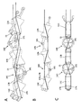
図1を参照して本発明の配管検査装置の例を説明する。本例の配管検査装置は、少なくとも1つの駆動ユニット1A、1Bと少なくとも1つの検査ユニット3を有する。図1には、2個の駆動ユニット、即ち、第1及び第2の駆動ユニット1A、1Bが例示されている。本例の配管検査装置は、配管5の内部を移動するように構成されている。検査ユニット3は検査デバイス30とその両側に接続されたケーブル31、32を有する。検査デバイス30には、配管の内面を検査するための検査素子が装填されている。検査素子は、検査の内容、目的、対象により異なる。検査ユニット3と駆動ユニットの間、駆動ユニット同士の間はコネクタ4によって接続されている。
An example of the pipe inspection apparatus of the present invention will be described with reference to FIG. The pipe inspection apparatus of this example includes at least one drive unit 1A, 1B and at least one inspection unit 3. FIG. 1 illustrates two drive units, that is, first and second drive units 1A and 1B. The pipe inspection apparatus of this example is configured to move inside the pipe 5. The inspection unit 3 includes an inspection device 30 and cables 31 and 32 connected to both sides thereof. The inspection device 30 is loaded with an inspection element for inspecting the inner surface of the pipe. The inspection element varies depending on the content, purpose, and object of inspection. A connector 4 connects between the inspection unit 3 and the drive unit, and between the drive units.
駆動ユニット1A、1Bには信号を伝送する信号線、電力を供給する電力ケーブルが接続されているが、図1では省略されている。
A signal line for transmitting signals and a power cable for supplying power are connected to the drive units 1A and 1B, but are omitted in FIG.
第1の駆動ユニット1Aを例として説明する。第1の駆動ユニット1Aは、複数の駆動部10A~10Eと複数の連結部13A~13Dと張力調節部20を有する。図示の駆動ユニット1Aは、5個の駆動部10A~10Eと4個の連結部13A~13Dを有するが、駆動部と連結部の数は同一であってもよく、異なってもよい。しかしながら、駆動ユニットの先頭には駆動部10Aが接続される。
The first drive unit 1A will be described as an example. The first drive unit 1A includes a plurality of drive units 10A to 10E, a plurality of connection units 13A to 13D, and a tension adjusting unit 20. The illustrated drive unit 1A includes five drive units 10A to 10E and four connection units 13A to 13D, but the number of drive units and connection units may be the same or different. However, the drive unit 10A is connected to the head of the drive unit.
全ての駆動部10A~10Eは同一構造であってよい。駆動部10Aは、車軸101と車輪103を有する。車軸101は、図示しないモータに接続されている。車輪103が回転することにより、駆動部10Aは前進又は後退する。全ての駆動部の車軸にモータを接続してもよいが、幾つかの駆動部では、車軸にモータを接続しなくてもよい。例えば、最後部の駆動部では、車軸にモータを接続しなくてもよい。駆動部の構造は、詳細な構造は後に説明する。
All the drive units 10A to 10E may have the same structure. The drive unit 10 </ b> A has an axle 101 and wheels 103. The axle 101 is connected to a motor (not shown). As the wheel 103 rotates, the drive unit 10A moves forward or backward. A motor may be connected to the axles of all the drive units, but in some drive units, the motors may not be connected to the axles. For example, in the last drive unit, the motor may not be connected to the axle. The detailed structure of the drive unit will be described later.
駆動部と連結部を2本の操縦用ケーブル17A、17Bが貫通している。2本の操縦用ケーブル17A、17Bは、先頭の駆動部から後尾の駆動部まで貫通しており、その後端は、張力調節部20に接続されている。2本の操縦用ケーブル17A、17Bは、張力調節部20によって引っ張られる。張力調節部20は2本の操縦用ケーブル17A、17Bの張力を独立に調節することができる。張力調節部20の構造の例は後に説明する。
The two steering cables 17A and 17B pass through the drive part and the connecting part. The two steering cables 17 </ b> A and 17 </ b> B penetrate from the leading drive unit to the rear drive unit, and the rear ends thereof are connected to the tension adjusting unit 20. The two steering cables 17 </ b> A and 17 </ b> B are pulled by the tension adjusting unit 20. The tension adjusting unit 20 can independently adjust the tension of the two steering cables 17A and 17B. An example of the structure of the tension adjusting unit 20 will be described later.
2本の操縦用ケーブル17A、17Bの機能を説明する。2本の操縦用ケーブル17A、17Bを互いに同一の張力によって引っ張ることによって、図示のように複数の駆動部10A~10Eはジグザグ状に屈折して配列される。図示の例では、先頭の駆動部10Aの車輪は、配管の一方の側の壁5Aの内面に接触しており、2番目の駆動部10Bの車輪は、配管の他方の側の壁5Bの内面に接触している。奇数番目の駆動部10A、10C、10Eの車輪は、配管の一方の側の壁5Aの内面に接触しており、偶数番目の駆動部10B、10Dの車輪は、配管の他方の側の壁5Bの内面に接触している。奇数番目の駆動部10A、10C、10Eの車輪は、図1において反時計方向に回転し、偶数番目の駆動部10B、10Dの車輪は、図1にて時計方向に回転する。それによって、奇数番目の駆動部10A、10C、10Eは、配管の壁5Aの内面上を矢印a方向に前進し、偶数番目の駆動部10B、10Dは、配管の壁5Bの内面上を矢印a方向に前進する。
The function of the two control cables 17A and 17B will be described. By pulling the two steering cables 17A and 17B with the same tension, the plurality of drive units 10A to 10E are refracted and arranged in a zigzag manner as shown in the figure. In the illustrated example, the wheel of the leading drive unit 10A is in contact with the inner surface of the wall 5A on one side of the pipe, and the wheel of the second drive unit 10B is the inner surface of the wall 5B on the other side of the pipe. Touching. The wheels of the odd-numbered drive units 10A, 10C, 10E are in contact with the inner surface of the wall 5A on one side of the pipe, and the wheels of the even-numbered drive units 10B, 10D are the wall 5B on the other side of the pipe. It is in contact with the inner surface. The wheels of the odd-numbered drive units 10A, 10C, 10E rotate counterclockwise in FIG. 1, and the wheels of the even-numbered drive units 10B, 10D rotate clockwise in FIG. Accordingly, the odd-numbered drive units 10A, 10C, and 10E advance in the direction of the arrow a on the inner surface of the pipe wall 5A, and the even-numbered drive units 10B and 10D move on the inner surface of the pipe wall 5B with the arrow a. Move forward in the direction.
2本の操縦用ケーブル17A、17Bを互いに異なる張力によって引っ張ることによって、複数の駆動部はジグザグ状に屈折し且つ螺旋状に配列されながら、配管内を螺旋状に進む。これについては、後に詳細に説明する。本例の配管検査装置では、2本の操縦用ケーブル17A、17Bを同一の張力によって引っ張る場合には、各駆動部10A~10Eは、配管の内壁上を直進するが、2本の操縦用ケーブル17A、17Bを互いに異なる張力によって引っ張る場合には、各駆動部10A~10Eは、配管の内壁上を螺旋状に進む。本例では、駆動ユニットは、2本の操縦用ケーブル17A、17Bの張力によって常にジグザグ状に屈折し且つ直線状又は螺旋状に配列されており、駆動部の車輪は常に配管の内面に接触している。駆動部の車輪を配管の内面に接触させるための接触力は、2本の操縦用ケーブル17A、17Bの張力の大きさに依存する。
By pulling the two control cables 17A and 17B with different tensions, the plurality of drive units are bent in a zigzag manner and arranged in a spiral manner, and advance in a spiral manner in the pipe. This will be described in detail later. In the pipe inspection apparatus of this example, when the two steering cables 17A and 17B are pulled with the same tension, each drive unit 10A to 10E goes straight on the inner wall of the pipe, but the two steering cables When pulling 17A and 17B with different tensions, the drive units 10A to 10E advance spirally on the inner wall of the pipe. In this example, the drive unit is always refracted in a zigzag shape by the tension of the two control cables 17A and 17B and arranged in a straight line or a spiral shape, and the wheel of the drive unit always contacts the inner surface of the pipe. ing. The contact force for bringing the wheels of the drive unit into contact with the inner surface of the pipe depends on the magnitude of the tension of the two steering cables 17A and 17B.
本例の配管検査装置を、配管の曲がり部及び分岐にて所望の方向に進行させる方法を説明する。配管の曲がり部又は分岐では、駆動部は、次の条件(1)を満たす必要がある。(1)先頭の駆動部の車軸は、配管の曲がり部又は分岐において配管の中心線を含む平面に垂直に配置される。更に、T字管、又は、Y字管のような配管の分岐では、駆動部は、次の条件(2)を満たす必要がある。(2)先頭の駆動部の車輪は、配管の分岐においては配管の進行すべき方向の内周側の内壁に接触している。
A method for advancing the pipe inspection apparatus of this example in a desired direction at a bent portion and a branch of the pipe will be described. In the bent part or branch of the piping, the drive part needs to satisfy the following condition (1). (1) The axle of the leading drive unit is arranged perpendicular to the plane including the center line of the pipe at the bent part or branch of the pipe. Furthermore, in branching of a pipe such as a T-shaped tube or a Y-shaped tube, the drive unit needs to satisfy the following condition (2). (2) The wheel of the leading drive unit is in contact with the inner wall on the inner peripheral side in the direction in which the pipe should travel in the branch of the pipe.
先ず、条件(1)について説明する。図1では、配管5は曲がり部51と分岐52を含む。曲がり部51では、配管の中心線を含む平面は、紙面に平行である。従って、曲がり部51では、先頭の駆動部10Aの車軸101は、配管の中心線を含む平面に垂直でなければならない。即ち、先頭の駆動部10Aの車軸101は、紙面に垂直でなければならない。同様に、分岐52では、配管の中心線を含む平面は、紙面に平行である。従って、分岐52では、先頭の駆動部10Aの車軸101は、配管の中心線を含む平面に垂直でなければならない。即ち、先頭の駆動部10Aの車軸101は、紙面に垂直でなければならない。図1の例では、曲がり部51を進む第1の駆動ユニット1Aと、分岐52を通過中の第2の駆動ユニット1Bでは、共に、先頭の駆動部10Aの車軸101は、紙面に垂直である。従って、条件(1)を満たしている。
First, condition (1) will be described. In FIG. 1, the pipe 5 includes a bent portion 51 and a branch 52. In the bent portion 51, the plane including the center line of the pipe is parallel to the paper surface. Therefore, in the bending part 51, the axle 101 of the leading drive part 10A must be perpendicular to the plane including the center line of the pipe. That is, the axle 101 of the leading drive unit 10A must be perpendicular to the paper surface. Similarly, in the branch 52, the plane including the center line of the pipe is parallel to the paper surface. Therefore, at the branch 52, the axle 101 of the leading drive unit 10A must be perpendicular to the plane including the center line of the pipe. That is, the axle 101 of the leading drive unit 10A must be perpendicular to the paper surface. In the example of FIG. 1, in both the first drive unit 1 </ b> A that travels through the bent portion 51 and the second drive unit 1 </ b> B that passes through the branch 52, the axle 101 of the leading drive unit 10 </ b> A is perpendicular to the paper surface. . Therefore, the condition (1) is satisfied.
次に条件(2)について説明する。曲がり部51では、進行方向右側に曲がるものとする。曲がり部51では、上述のように条件(2)は必要ない。従って、配管の曲がる側の内周側の壁51Bの内面に、先頭の駆動部10Aの車輪が接触している必要はない。第1の駆動ユニット1Aでは、先頭の駆動部10Aの車輪は、外周側の壁51Aの内面に接触している。従って、条件(2)を満たしていない。しかしながら、先頭の駆動部10Aの車輪は、そのまま、曲がり部51の湾曲した内壁に沿って進行する。
Next, condition (2) will be described. In the bending part 51, it shall bend to the right side of the advancing direction. In the bent part 51, the condition (2) is not necessary as described above. Therefore, it is not necessary that the wheel of the leading drive unit 10A is in contact with the inner surface of the inner peripheral wall 51B on the side where the pipe is bent. In the first drive unit 1A, the wheel of the leading drive unit 10A is in contact with the inner surface of the outer peripheral wall 51A. Therefore, the condition (2) is not satisfied. However, the wheel of the leading drive unit 10 </ b> A travels along the curved inner wall of the bent part 51 as it is.
分岐52では、進行方向左側に曲がるものとする。従って、配管の曲がる側の内周側の壁52Aの内面に、先頭の駆動部10Aの車輪が接触している必要がある。第2の駆動ユニット1Bでは、先頭の駆動部10Aの車輪は、内周側の壁52Aの内面に接触している。従って、条件(2)を満たしている。
Suppose that the branch 52 turns to the left in the traveling direction. Therefore, it is necessary that the wheel of the leading drive unit 10A is in contact with the inner surface of the inner peripheral wall 52A on the side where the pipe is bent. In the second drive unit 1B, the wheel of the leading drive unit 10A is in contact with the inner surface of the inner peripheral wall 52A. Therefore, the condition (2) is satisfied.
本発明の配管検査装置の動作を説明する。本例の配管検査装置を操作するには、先ず、検査対象の配管の設計データ、又は、CADデータを入手する必要である。次に、操作者は、配管検査装置の移動経路を予め設定する。即ち、配管網上の始点と終点を設定し、次に、始点と終点の間の配管網に含まれる曲がり管の曲がり方向と分岐管の分岐の進行方向を予め検出する。こうして、経路に関する情報が得られると、配管検査装置を、始点にて、即ち、配管の入り口より内部に挿入する。駆動ユニットの駆動部を駆動させることにより、配管検査装置は、配管内を自走する。
The operation of the pipe inspection apparatus of the present invention will be described. In order to operate the pipe inspection apparatus of this example, it is first necessary to obtain design data or CAD data of the pipe to be inspected. Next, the operator presets the movement route of the pipe inspection device. That is, the start point and end point on the piping network are set, and then the bending direction of the bent pipe and the branching direction of the branch pipe included in the piping network between the start point and the end point are detected in advance. Thus, when the information regarding the route is obtained, the pipe inspection device is inserted into the start point, that is, from the entrance of the pipe. By driving the drive unit of the drive unit, the pipe inspection device is self-propelled in the pipe.
配管検査装置が配管内に進入したら、最も先頭の駆動部の位置をリアルタイムにて検出する必要がある。最も先頭の駆動部の位置を検出するには、配管内に進入した配管検査装置の長さを求めればよい。これは、配管の入り口にて、配管内に挿入された駆動ユニットと検査ユニットの数より求められる。駆動ユニットと検査ユニットの長さは、それぞれ既知である。尚、ここで、駆動ユニットの長さは、配管内においてジグザグ状又は螺旋状に屈折した駆動ユニットを、配管の中心線に沿って測定した長さである。駆動ユニットの長さに個数を乗算することにより、駆動ユニットの長さの合計が得られる。検査ユニットの長さに個数を乗算することにより、検査ユニットの長さの合計が得られる。両者の合計の和が、配管内に挿入された配管検査装置の長さである。尚、配管内に進入した配管検査装置の長さを測定するために、長さ測定用の特別のケーブルを使用してもよい。
When the pipe inspection device enters the pipe, it is necessary to detect the position of the head drive unit in real time. In order to detect the position of the head drive unit, the length of the pipe inspection device that has entered the pipe may be obtained. This is obtained from the number of drive units and inspection units inserted into the pipe at the inlet of the pipe. The lengths of the drive unit and the inspection unit are each known. Here, the length of the drive unit is a length obtained by measuring the drive unit refracted in a zigzag shape or a spiral shape in the pipe along the center line of the pipe. By multiplying the length of the drive unit by the number, the total length of the drive unit is obtained. By multiplying the length of the inspection unit by the number, the total length of the inspection unit is obtained. The sum of both is the length of the pipe inspection device inserted into the pipe. In order to measure the length of the pipe inspection apparatus that has entered the pipe, a special cable for measuring the length may be used.
こうして、配管内に挿入された配管検査装置の長さが求められれば、それと配管の設計データから、配管検査装置の最も先頭の駆動部の位置が得られる。
Thus, if the length of the pipe inspection apparatus inserted into the pipe is obtained, the position of the head drive unit of the pipe inspection apparatus can be obtained from the pipe design data.
配管検査装置の先頭の駆動部が、配管の曲がり部又は分岐に近づいたら、先頭の駆動部の車軸の方向を検出する必要がある。本例の配管検査装置によると、先頭の駆動部には、車軸の方向を検出するための姿勢検出センサが設けられている。姿勢検出センサは、例えば、加速度計であってよい。姿勢検出センサによって検出された先頭の駆動部の車軸の方向は、リアルタイムにて、操作者に送信される。例えば、先頭の駆動部の姿勢検出センサに接続された信号ケーブルは、配管検査装置に沿って、配管の入り口まで延びている。操作者は、この信号ケーブルを介して、姿勢検出センサの出力を得ることができる。姿勢検出センサは、各駆動ユニットの先端の駆動部に設けられる。従って、各駆動ユニットの先端の駆動部の位置がリアルタイムにて得られる。
When the head drive part of the pipe inspection device approaches the bent part or branch of the pipe, it is necessary to detect the direction of the axle of the head drive part. According to the pipe inspection apparatus of this example, the head drive unit is provided with an attitude detection sensor for detecting the direction of the axle. The posture detection sensor may be an accelerometer, for example. The direction of the axle of the leading drive unit detected by the attitude detection sensor is transmitted to the operator in real time. For example, the signal cable connected to the attitude detection sensor of the leading drive unit extends to the entrance of the pipe along the pipe inspection device. The operator can obtain the output of the attitude detection sensor via this signal cable. The posture detection sensor is provided in the drive unit at the tip of each drive unit. Therefore, the position of the drive unit at the tip of each drive unit can be obtained in real time.
操作者は、配管検査装置の先頭の駆動部が、配管の曲がり部に近づいたとき、上述の第1の条件が満たされているか否かを判定する。操作者は、配管検査装置の先頭の駆動部が、配管の分岐に近づいたとき、上述の第1及び第2の条件が満たされているか否かを判定する。先頭の駆動部には、配管の内部を撮像する撮像装置、例えば、CCDカメラが設けられてよい。第1の条件が満たされていない場合には、先頭の駆動部の車軸が、配管の中心線を含む平面に垂直となるように、先頭の駆動部を回転させる必要がある。先頭の駆動部を回転させるには、先頭の駆動部を螺旋状に進行させればよい。先頭の駆動部を螺旋状に進行させるには、2つの操縦用ケーブル17A、17Bを互いに異なる張力によって引っ張ればよい。
The operator determines whether or not the first condition is satisfied when the leading drive unit of the pipe inspection apparatus approaches the bent part of the pipe. The operator determines whether or not the first and second conditions described above are satisfied when the leading drive unit of the pipe inspection device approaches the branch of the pipe. The leading drive unit may be provided with an imaging device that images the inside of the pipe, for example, a CCD camera. When the first condition is not satisfied, it is necessary to rotate the leading drive unit so that the axle of the leading drive unit is perpendicular to the plane including the center line of the pipe. In order to rotate the leading drive unit, the leading drive unit may be spirally advanced. In order to advance the leading drive portion in a spiral shape, the two steering cables 17A and 17B may be pulled with different tensions.
第2の条件が満たされていない場合には、先頭の駆動部の車軸が、進行すべき方向の配管の内周側の内壁に接触するように、先頭の駆動部の車軸の方向を回転させる必要がある。先頭の駆動部の車軸の方向を回転させるには、先頭の駆動部を螺旋状に進行させればよい。先頭の駆動部を螺旋状に進行させるには、2つの操縦用ケーブル17A、17Bを互いに異なる張力によって引っ張ればよい。こうして、2つの操縦用ケーブル17A、17Bを互いに異なる張力によって引っ張ることにより、上述の2つの条件を満たすことができる。操作者は、配管の曲がり部の直前にて、先頭の駆動部の姿勢検出センサからの信号出力より、第1の条件が満たされているか否かを確認することができる。操作者は、配管の分岐の直前にて、先頭の駆動部の姿勢検出センサからの信号出力より、第1及び第2の条件が満たされているか否かを確認することができる。
When the second condition is not satisfied, the axle direction of the leading drive unit is rotated so that the axle of the leading drive unit contacts the inner wall on the inner peripheral side of the pipe in the direction to travel. There is a need. In order to rotate the direction of the axle of the leading drive unit, the leading drive unit may be spirally advanced. In order to advance the leading drive portion in a spiral shape, the two steering cables 17A and 17B may be pulled with different tensions. Thus, by pulling the two steering cables 17A and 17B with different tensions, the above two conditions can be satisfied. The operator can confirm whether or not the first condition is satisfied from the signal output from the attitude detection sensor of the leading drive unit immediately before the bent portion of the pipe. The operator can confirm whether or not the first and second conditions are satisfied from the signal output from the attitude detection sensor of the leading drive unit immediately before the branching of the pipe.
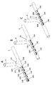
図2は駆動ユニットの例を示す。本例の駆動ユニットは、複数の駆動部10A~10Eと複数の連結部13A~13Dと張力調節部20を有する。駆動部と連結部を2本の操縦用ケーブル17A、17Bが貫通している。駆動ユニットの先端と後端には、コネクタ4が接続されている。2本の操縦用ケーブル17A、17Bは、先頭の駆動部から後尾の駆動部まで貫通しており、その後端は、張力調節部20に接続されている。2本の操縦用ケーブル17A、17Bには、バネ18A、18Bが設けられている。これらのバネ 18A、18Bは、それぞれチューブワイヤの内部に格納されている。そのため2本のバネ18A、18Bの引っ張り力によって、コネクタ4の間の駆動ユニットの長さは変えずに2本の操縦用ケーブル17A、17Bに張力を生成できるようになっている。
Fig. 2 shows an example of a drive unit. The drive unit of this example includes a plurality of drive units 10A to 10E, a plurality of connection units 13A to 13D, and a tension adjusting unit 20. Two steering cables 17A and 17B pass through the drive part and the connecting part. A connector 4 is connected to the front end and the rear end of the drive unit. The two steering cables 17 </ b> A and 17 </ b> B penetrate from the leading drive unit to the rear drive unit, and the rear ends thereof are connected to the tension adjusting unit 20. Two steering cables 17A and 17B are provided with springs 18A and 18B. These spring rods 18A and 18B are respectively stored inside the tube wires. Therefore, tension can be generated in the two steering cables 17A and 17B without changing the length of the drive unit between the connectors 4 by the pulling force of the two springs 18A and 18B.
張力調節部20は、操縦用ケーブル17A、17Bを巻き取るためのリール21と車輪22を有する。リール21は図示しないモータによって回転する。リール21によって2本の操縦用ケーブル17A、17Bをそれぞれ逆向きに巻き取ることができる。このリール21の回転で、2本の操縦用ケーブルの張力のバランスを変えることができる。上述のように、先頭の駆動部を螺旋状に進行させるには、2つの操縦用ケーブル17A、17Bを互いに異なる張力になるように一方向に回転させればよい。駆動部を直線状に進行させる場合には、2つの操縦用ケーブル17A、17Bを互いに同一の張力になるようにリール21の回転角度を調整すればよい。
The tension adjusting unit 20 includes a reel 21 and a wheel 22 for winding the steering cables 17A and 17B. The reel 21 is rotated by a motor (not shown). The two control cables 17A and 17B can be wound up in opposite directions by the reel 21. The rotation of the reel 21 can change the balance of tension between the two control cables. As described above, in order to advance the leading drive unit in a spiral shape, the two steering cables 17A and 17B may be rotated in one direction so as to have different tensions. In the case where the drive unit is moved linearly, the rotation angle of the reel 21 may be adjusted so that the two steering cables 17A and 17B have the same tension.
操縦用ケーブル17A、17Bを別々のリールで引っ張る機構によってもよい。この場合は、リール駆動機構が2倍必要であり、また配管移動中に常にケーブルを牽引し続ける必要があり、エネルギを常時必要とする。しかしながら、この場合、操縦用ケーブル17A、17Bの張力のバランスのみならず、張力自体が可変となるため、配管内の移動状況に応じて、あるいは、配管から引き出す場合などに、各車輪の配管内壁に接触させる接触力を調整できるという効果を生成する。
A mechanism for pulling the control cables 17A and 17B with separate reels may be used. In this case, it is necessary to double the reel drive mechanism, and it is necessary to always pull the cable while moving the pipe, and energy is always required. However, in this case, since not only the balance of the tension of the steering cables 17A and 17B but also the tension itself is variable, the inner wall of the pipe of each wheel according to the movement state in the pipe or when pulling out from the pipe. This produces an effect that the contact force to be brought into contact with can be adjusted.
さらに、操縦用ケーブル17A、17Bを別々のリールで引っ張る機構と同様の効果を、操縦用ケーブル17A、17Bを巻き取るためのリール21と車輪22をコネクタ4の間の駆動ユニットの長さ方向に移動して操縦用ケーブル17A、17Bの張力を同時に変える駆動系を導入することで実現することもできる。
Further, the same effect as the mechanism of pulling the steering cables 17A and 17B with separate reels is obtained, and the reel 21 and the wheel 22 for winding the steering cables 17A and 17B are arranged in the length direction of the drive unit between the connectors 4. It can also be realized by introducing a drive system that moves and changes the tension of the steering cables 17A and 17B at the same time.
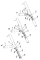
図3A、図3B及び図3Cを参照して、駆動ユニットの構造の例を説明する。図3Aは駆動ユニットの一部を示す斜視図であり、図3Bは駆動ユニットの一部の側面構成を示す図であり、図3Cは駆動ユニットの一部の平面構成を示す図である。ここでは、3つの連結部13A、13B、13Cと第2及び第3の駆動部10B、10Cのみを示す。更に、各駆動部の構造の一部のみを示す。図3Aの第2の駆動部10Bについて説明する。車軸101には車輪が装着されているが、図示は省略されている。車軸101には、アーム105、106が枢動可能に装着されている。一方のアーム105は後側の連結部13Bに装着されている。他方のアーム106は、連結軸15を介して、前側の連結部13Aに接続されている。
An example of the structure of the drive unit will be described with reference to FIGS. 3A, 3B, and 3C. 3A is a perspective view illustrating a part of the drive unit, FIG. 3B is a diagram illustrating a side configuration of a part of the drive unit, and FIG. 3C is a diagram illustrating a planar configuration of a part of the drive unit. Here, only the three connecting portions 13A, 13B, and 13C and the second and third driving portions 10B and 10C are shown. Furthermore, only a part of the structure of each drive unit is shown. The second drive unit 10B in FIG. 3A will be described. Although the wheel is mounted on the axle 101, the illustration is omitted. Arms 105 and 106 are pivotally mounted on the axle 101. One arm 105 is attached to the connecting portion 13B on the rear side. The other arm 106 is connected to the front connecting portion 13 </ b> A via the connecting shaft 15.
車軸101の中心軸線は、後側の連結部13Bの中心軸線に直交している。連結軸15の中心軸線は、前側の連結部13Aの中心軸線に直交している。車軸101の中心軸線は、連結軸15の中心軸線に垂直である。車軸101と連結軸15によってジンバル構造が形成される。このジンバル構造によって、2つの連結部13A、13Bは、車軸101の中心軸線周りに互いに他に対して枢動可能であり、連結部13Aと駆動部10Bは、連結軸15の中心軸線周りに互いに他に対して枢動可能である。
The center axis of the axle 101 is orthogonal to the center axis of the rear connecting portion 13B. The central axis of the connecting shaft 15 is orthogonal to the central axis of the front connecting portion 13A. The central axis of the axle 101 is perpendicular to the central axis of the connecting shaft 15. The axle 101 and the connecting shaft 15 form a gimbal structure. With this gimbal structure, the two connecting portions 13A and 13B can be pivoted with respect to each other around the central axis of the axle 101, and the connecting portion 13A and the driving portion 10B can be mutually connected around the central axis of the connecting shaft 15. Can pivot with respect to others.
2本の操縦用ケーブル17A、17Bが、駆動部10B、10Cと連結部13A~13Cを貫通している。連結部13A~13Cには、2本の操縦用ケーブル17A、17Bが通るための孔が形成されている。2本の操縦用ケーブル17A、17Bは連結部13A~13Cに設けられた孔によって拘束される。従って、連結部13A~13C内における2本の操縦用ケーブル17A、17Bの位置及び経路は一定である。
The two steering cables 17A and 17B penetrate the drive units 10B and 10C and the coupling units 13A to 13C. The connecting portions 13A to 13C are formed with holes through which the two steering cables 17A and 17B pass. The two steering cables 17A and 17B are restrained by holes provided in the connecting portions 13A to 13C. Accordingly, the positions and paths of the two steering cables 17A and 17B in the connecting portions 13A to 13C are constant.
本例では、2本の操縦用ケーブル17A、17Bは引っ張られていない。従って、連結部13A~13Cは1直線に沿って配置されている。配管検査装置を実際に配管内にて移動させる場合には、必ず、2本の操縦用ケーブル17A、17Bは引っ張られる。図3A、図3B及び図3Cに示す配管検査装置は、未だ、配管内に挿入されていない状態を示す。
In this example, the two control cables 17A and 17B are not pulled. Accordingly, the connecting portions 13A to 13C are arranged along one straight line. When the pipe inspection device is actually moved in the pipe, the two steering cables 17A and 17B are always pulled. The pipe inspection apparatus shown in FIGS. 3A, 3B, and 3C shows a state where the pipe inspection apparatus is not yet inserted into the pipe.
図3Bに示すように、駆動部の車軸101に垂直な面を想定し、この面に2本の操縦用ケーブル17A、17Bを投影すると、両者は重なり合っている。2本の操縦用ケーブル17A、17Bの投影線は、連結部では、その対角線に沿って走行しており、駆動部では、互い違いに、駆動部の片方側を通っている。図3Cに示すように、連結軸15に垂直な面を想定し、この面に2本の操縦用ケーブル17A、17Bを投影すると、両者は連結部では、平行に走行し、駆動部では交差している。
As shown in FIG. 3B, assuming a plane perpendicular to the axle 101 of the drive unit and projecting the two steering cables 17A and 17B on this plane, they overlap each other. The projection lines of the two steering cables 17A and 17B run along the diagonal line in the connecting portion, and alternately pass through one side of the driving portion in the driving portion. As shown in FIG. 3C, assuming a plane perpendicular to the connecting shaft 15 and projecting the two steering cables 17A and 17B on this plane, they run in parallel at the connecting portion and intersect at the driving portion. ing.
図4A、図4B及び図4Cを参照して、駆動ユニットの動作を説明する。本例では、2本の操縦用ケーブル17A、17Bは同一の張力によって引っ張られている。従って、図4Bに示すように、駆動部の車軸101に垂直な面に2本の操縦用ケーブル17A、17Bを投影すると、2本の操縦用ケーブルの投影線は、図3Bの場合と比較して、直線化している。即ち、2本の操縦用ケーブル17A、17Bを同一の張力によって引っ張ることによって、連結部13A~13Cは、車軸101の中心軸線周りに互いに枢動する。その結果、図4Bに示すように、駆動部10B、10Cと連結部13A~13Cは、ジグザグ状に屈折する。図4Cに示すように、駆動部10B、10Cと連結部13A~13Cは、連結軸15の中心軸線周り枢動していない。本例では、駆動部の車輪が回転すると、車輪が配管の内壁に接触した状態で、駆動部は、配管の内壁に沿って直線的に移動する。
The operation of the drive unit will be described with reference to FIGS. 4A, 4B, and 4C. In this example, the two steering cables 17A and 17B are pulled by the same tension. Therefore, as shown in FIG. 4B, when the two steering cables 17A and 17B are projected onto a plane perpendicular to the axle 101 of the drive unit, the projection lines of the two steering cables are compared with the case of FIG. 3B. Is linearized. That is, by pulling the two steering cables 17A and 17B with the same tension, the connecting portions 13A to 13C pivot about each other around the central axis of the axle 101. As a result, as shown in FIG. 4B, the driving units 10B and 10C and the coupling units 13A to 13C are refracted in a zigzag shape. As shown in FIG. 4C, the drive units 10B and 10C and the connecting portions 13A to 13C are not pivoted around the central axis of the connecting shaft 15. In this example, when the wheel of the drive unit rotates, the drive unit moves linearly along the inner wall of the pipe with the wheel in contact with the inner wall of the pipe.
図5A、図5B及び図5Cを参照して、駆動ユニットの動作を説明する。本例では、2本の操縦用ケーブル17A、17Bは互いに異なる張力によって引っ張られている。図5Bに示すように、駆動部の車軸101周りに、2つの連結部は互いに枢動しており、更に、図5Cに示すように、連結軸15周りに駆動部と連結部は互いに枢動している。従って、配管検査装置は、ジグザグ状に屈折し且つ螺旋状に配列されている。本例では、駆動部の車輪が回転すると、車輪が配管の内壁に接触した状態で、駆動部は、配管の内壁に沿って螺旋状に移動する。
The operation of the drive unit will be described with reference to FIGS. 5A, 5B, and 5C. In this example, the two steering cables 17A and 17B are pulled by different tensions. As shown in FIG. 5B, the two connecting parts pivot around each other around the axle 101 of the driving part. Further, as shown in FIG. 5C, the driving part and the connecting part pivot around each other around the connecting shaft 15. is doing. Therefore, the pipe inspection device is refracted in a zigzag shape and arranged in a spiral shape. In this example, when the wheel of the drive unit rotates, the drive unit spirally moves along the inner wall of the pipe in a state where the wheel contacts the inner wall of the pipe.
図6A、図6B及び図6Cを参照して、本例の配管検査装置が分岐を移動する場合を説明する。配管5から分岐52において分岐管6が接続されているものとする。本例では、分岐52の直前において、配管検査装置の先頭の駆動部10Aの車軸101は、配管の中心線を含む平面に垂直に配置されていない。従って、上述の条件(1)を満たしていない。従って、このままでは、配管検査装置は、配管5から分岐52を経由して分岐管6に移動することはない。図6B及び図6Cに示すように、配管検査装置は、分岐52を通過して配管5を走行し続ける。
Referring to FIGS. 6A, 6B, and 6C, the case where the pipe inspection apparatus of this example moves a branch will be described. It is assumed that the branch pipe 6 is connected from the pipe 5 to the branch 52. In this example, immediately before the branch 52, the axle 101 of the leading drive unit 10A of the pipe inspection apparatus is not arranged perpendicular to a plane including the center line of the pipe. Therefore, the above condition (1) is not satisfied. Therefore, in this state, the pipe inspection device does not move from the pipe 5 to the branch pipe 6 via the branch 52. As shown in FIGS. 6B and 6C, the pipe inspection device continues to travel on the pipe 5 through the branch 52.
図7A、図7B及び図7Cを参照して、本例の配管検査装置が分岐を移動する場合を説明する。本例では、分岐52の直前において、配管検査装置の先頭の駆動部10Aの車軸101は、配管の中心線を含む平面に垂直に配置されている。従って、上述の条件(1)を満たしている。更に、先頭の駆動部10Aの車輪は、分岐において、進行すべき方向の配管の内周側の壁52Aの内面に接触している。従って、上述の条件(2)を満たしている。従って、配管検査装置は、配管5から分岐52を経由して分岐管6に移動することができる。図7B及び図7Cに示すように、配管検査装置は、分岐52を通過して分岐管6に進路を変更することができる。
Referring to FIGS. 7A, 7B and 7C, the case where the pipe inspection apparatus of this example moves a branch will be described. In this example, immediately before the branch 52, the axle 101 of the leading drive unit 10A of the pipe inspection device is disposed perpendicular to a plane including the center line of the pipe. Therefore, the above condition (1) is satisfied. Further, the wheel of the leading drive unit 10A is in contact with the inner surface of the inner peripheral wall 52A of the pipe in the direction to travel at the branch. Therefore, the above condition (2) is satisfied. Therefore, the pipe inspection device can move from the pipe 5 to the branch pipe 6 via the branch 52. As shown in FIGS. 7B and 7C, the pipe inspection apparatus can change the course to the branch pipe 6 through the branch 52.
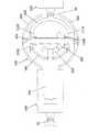
図8を参照して、駆動部と連結部の構造の例を説明する。駆動部10Bは、車軸101と、車軸の両端に装着された半球面状の車輪103と、車軸101に装着された第1の傘歯車107とを有する。車軸101には、玉軸受け110A、110Bを介して第1のアーム105が装着されている。従って、第1のアーム105は、玉軸受け110A、110Bを介して車軸101の周りを自在に回転することができる。第1のアーム105には、玉軸受け111A、111Bを介して、第2のアーム106が装着されている。従って、第2のアーム106は、玉軸受け111A、111Bを介して第1のアーム105に対して自在に枢動することができる。こうして、第1のアーム105と第2のアーム106は、車軸101の中心軸線周りに、互いに他に対して枢動可能である。
Referring to FIG. 8, an example of the structure of the drive unit and the connection unit will be described. The drive unit 10 </ b> B includes an axle 101, hemispherical wheels 103 attached to both ends of the axle, and a first bevel gear 107 attached to the axle 101. A first arm 105 is attached to the axle 101 via ball bearings 110A and 110B. Accordingly, the first arm 105 can freely rotate around the axle 101 via the ball bearings 110A and 110B. A second arm 106 is attached to the first arm 105 via ball bearings 111A and 111B. Therefore, the second arm 106 can freely pivot with respect to the first arm 105 via the ball bearings 111A and 111B. Thus, the first arm 105 and the second arm 106 can pivot relative to each other around the central axis of the axle 101.
後側の連結部13Bにはモータ131が装着されている。モータ131の軸には、第2の傘歯車108が装着されている。第2の傘歯車108は第1の傘歯車107に噛み合っている。更に、モータ131には、第1のアーム105が装着されている。尚、モータ131の代わりに後側の連結部13Bに、第1のアーム105が装着されてもよい。上述のように、第1のアーム105は車軸101の中心軸線周りに、枢動可能である。従って、第1のアーム105に接続されたモータ131、及びモータ131を支持する連結部13Bは、車軸101の中心軸線周りに、枢動可能である。
A motor 131 is attached to the rear connecting portion 13B. A second bevel gear 108 is attached to the shaft of the motor 131. The second bevel gear 108 meshes with the first bevel gear 107. Further, the first arm 105 is attached to the motor 131. The first arm 105 may be attached to the rear connecting portion 13B instead of the motor 131. As described above, the first arm 105 can pivot about the central axis of the axle 101. Therefore, the motor 131 connected to the first arm 105 and the connecting portion 13 </ b> B that supports the motor 131 can be pivoted around the central axis of the axle 101.
第2のアーム106は、連結軸15を介して前側の連結部13Aに枢動可能に接続されている。上述のように、第2のアーム106は車軸101の中心軸線周りに、枢動可能である。従って、第2のアーム106に接続された前側の連結部13Aは、車軸101の中心軸線周りに、枢動可能である。
The second arm 106 is pivotally connected to the front connecting portion 13A via the connecting shaft 15. As described above, the second arm 106 can pivot about the central axis of the axle 101. Accordingly, the front connecting portion 13 </ b> A connected to the second arm 106 can pivot around the central axis of the axle 101.
車軸101と連結軸15は直交している。車軸101と連結軸15によってジンバル構造が構成される。また、車軸101とモータ131の軸は直交している。
The axle 101 and the connecting shaft 15 are orthogonal to each other. The axle 101 and the connecting shaft 15 constitute a gimbal structure. The axle 101 and the motor 131 are orthogonal to each other.
モータ131が駆動すると、その軸に装着された第2の傘歯車108が回転する。第2の傘歯車108の回転は、第1の傘歯車107に伝達され、車軸101が回転する。車軸101が回転すると、車輪103が回転する。
When the motor 131 is driven, the second bevel gear 108 mounted on the shaft rotates. The rotation of the second bevel gear 108 is transmitted to the first bevel gear 107 and the axle 101 rotates. When the axle 101 rotates, the wheel 103 rotates.
2本の操縦用ケーブルの張力を調節することにより、連結部13A、13Bは車軸101周りに枢動する。更に、連結部13Bは連結軸15周りに枢動する。それによって、配管検査装置の駆動ユニットがジグザグ状に屈折し、更に、螺旋状に配列される。
The connecting portions 13A and 13B pivot around the axle 101 by adjusting the tension of the two steering cables. Further, the connecting portion 13B pivots around the connecting shaft 15. Thereby, the drive unit of the pipe inspection device is refracted in a zigzag shape and further arranged in a spiral shape.
図8に示した駆動部の構造は単なる1例である。駆動部と連結部を有する駆動ユニットが、ジグザグ状に屈折し、更に、螺旋状に配列することができれば、他の構造でもよい。例えば、図8の例ではモータ131を連結部に設けたが、モータを駆動部に設けてもよい。更に、本例では、車軸101とモータ131の軸は直交しているが、車軸101とモータ131の軸を同一方向に配置するように構成してもよい。この場合には、傘歯車の代わりに平歯車列が用いられる。更に、本例では、車輪103を半球状に形成しているが、タイヤ状であってもよい。車輪は、金属製であってもよいが、ゴム製であってよい。
The structure of the drive unit shown in FIG. 8 is merely an example. Other structures may be used as long as the drive unit having the drive part and the connecting part is refracted in a zigzag shape and can be arranged in a spiral shape. For example, in the example of FIG. 8, the motor 131 is provided in the connecting portion, but the motor may be provided in the driving portion. Further, in this example, the axle 101 and the motor 131 are orthogonal to each other, but the axle 101 and the motor 131 may be arranged in the same direction. In this case, a spur gear train is used instead of the bevel gear. Furthermore, in this example, although the wheel 103 is formed in a hemispherical shape, it may be a tire shape. The wheel may be made of metal but may be made of rubber.
以上本発明の例を説明したが本発明は上述の例に限定されるものではなく、特許請求の範囲に記載された発明の範囲にて様々な変更が可能であることは、当業者によって容易に理解されよう。
Although the examples of the present invention have been described above, the present invention is not limited to the above-described examples, and it is easy for those skilled in the art to make various modifications within the scope of the invention described in the claims. Will be understood.
1A,1B…駆動ユニット、3…検査ユニット、4…コネクタ、5…配管、5A,5B…配管の壁、6…分岐管、10A~10E…駆動部、13A~13D…連結部、20…張力調節部、17A,17B…操縦用ケーブル、18A,18B…バネ、21…リール、22…車輪、15…連結軸、30…検査素子、31,32…ケーブル、51…曲がり部、52…分岐、101…車軸、103…車輪、105,106…アーム、107,108…傘歯車、131…モータ
DESCRIPTION OF SYMBOLS 1A, 1B ... Drive unit, 3 ... Inspection unit, 4 ... Connector, 5 ... Pipe, 5A, 5B ... Pipe wall, 6 ... Branch pipe, 10A-10E ... Drive part, 13A-13D ... Connection part, 20 ... Tension Adjustment part, 17A, 17B ... Steering cable, 18A, 18B ... Spring, 21 ... Reel, 22 ... Wheel, 15 ... Connecting shaft, 30 ... Inspection element, 31, 32 ... Cable, 51 ... Bending part, 52 ... Branch, DESCRIPTION OF SYMBOLS 101 ... Axle, 103 ... Wheel, 105, 106 ... Arm, 107, 108 ... Bevel gear, 131 ... Motor
Claims (9)
- 少なくとも1個の駆動ユニットと少なくとも1個の検査ユニットとを有し、検査対象の配管内に挿入可能な配管検査装置において、
前記駆動ユニットは、複数の駆動部と、該駆動部を連結する複数の連結部と、前記駆動部及び前記連結部を通る2本の操縦用ケーブルと、該操縦用ケーブルの張力を調節する張力調節部とを有し、前記駆動部はモータによって回転可能な車軸と、該車軸に装着された車輪とを有し、
前記2本の操縦用ケーブルを互いに同一の張力によって引っ張ることによって、前記駆動ユニットはジグザグ状に屈折し、前記駆動部の車輪が前記配管の内壁に接触した状態で、前記駆動ユニットは直進し、
前記2本の操縦用ケーブルを互いに異なる張力によって引っ張ることによって、前記駆動ユニットはジグザグ状に屈折し且つ螺旋状に配列し、前記駆動部の車輪が前記配管の内壁に接触した状態で、前記駆動ユニットは螺旋状に進むように構成されている配管検査装置。 In a pipe inspection apparatus that has at least one drive unit and at least one inspection unit and can be inserted into a pipe to be inspected,
The drive unit includes a plurality of drive units, a plurality of connection units that connect the drive units, two control cables that pass through the drive unit and the connection units, and a tension that adjusts the tension of the control cable. An adjustment portion, and the drive portion includes an axle that can be rotated by a motor, and a wheel that is attached to the axle.
By pulling the two control cables with the same tension, the drive unit is refracted in a zigzag shape, and the drive unit goes straight with the wheels of the drive unit in contact with the inner wall of the pipe.
By pulling the two steering cables with different tensions, the drive unit is refracted in a zigzag shape and arranged in a spiral shape, and the drive unit wheel is in contact with the inner wall of the pipe. The pipe inspection device is configured so that the unit proceeds in a spiral. - 請求項1記載の配管検査装置において、
前記駆動部と前記連結部は互いに直交する2つの枢動軸を有するジンバル構造によって接続されており、前記駆動部及び前記連結部が前記2つの枢動軸周りに枢動することによって、前記駆動ユニットはジグザグ状に屈折し且つ直線状又は螺旋状に配列することができるように構成されていることを特徴とする配管検査装置。 In the piping inspection device according to claim 1,
The driving part and the connecting part are connected by a gimbal structure having two pivot axes orthogonal to each other, and the driving part and the connecting part pivot around the two pivot axes, thereby driving the driving part. The pipe inspection apparatus, wherein the unit is configured to be refracted in a zigzag shape and arranged in a straight line shape or a spiral shape. - 請求項1記載の配管検査装置において、
前記駆動ユニットは、2つの連結部と該2つの連結部の間に設けられた中間の駆動部を含み、
前記2つの連結部は前記中間の駆動部の車軸の周りに枢動可能であり、前記2つの連結部の一方の連結部は前記中間の駆動部に対して、前記車軸に対して直交するように配置された連結軸の周りに枢動可能であり、前記中間の駆動部の車軸と前記連結軸によって、前記2つの連結部は前記中間の駆動部を介して屈折することができるように構成されている配管検査装置。 In the piping inspection device according to claim 1,
The drive unit includes two connecting portions and an intermediate driving portion provided between the two connecting portions,
The two connecting parts are pivotable about an axle of the intermediate drive part, and one of the two connection parts is perpendicular to the axle with respect to the intermediate drive part. It is possible to pivot around a connecting shaft arranged at the center, and the two connecting portions can be refracted through the intermediate driving portion by the axle and the connecting shaft of the intermediate driving portion. Piping inspection equipment. - 請求項1記載の配管検査装置において、
前記駆動部と前記連結部は、2つの連結部と該2つの連結部の間に設けられた中間の駆動部を含み、
前記中間の駆動部は、車軸の周りに枢動可能な第1及び第2のアームを有し、前記第1のアームは前記2つの連結部の一方の連結部に装着され、前記第2のアームは、前記車軸に対して直交するように配置された連結軸を介して前記2つの連結部の他方の連結部に接続され、前記2つの連結部は、前記中間の駆動部の車軸の周りに互いに他に対して枢動可能であり、該駆動部と前記他方の連結部は、前記連結軸の周りに枢動可能であることを特徴とする配管検査装置。 In the piping inspection device according to claim 1,
The driving part and the connecting part include two connecting parts and an intermediate driving part provided between the two connecting parts,
The intermediate drive unit includes first and second arms pivotable around an axle, and the first arm is attached to one of the two connection units, and the second The arm is connected to the other connecting portion of the two connecting portions via a connecting shaft disposed so as to be orthogonal to the axle, and the two connecting portions are arranged around the axle of the intermediate drive portion. The pipe inspection device is capable of pivoting with respect to each other, and the driving portion and the other connecting portion can be pivoted around the connecting shaft. - 請求項1記載の配管検査装置において、
前記駆動部は、モータと、前記車軸に装着された第1の傘歯車と、前記モータの軸に装着され前記第1の傘歯車と噛み合う第2の傘歯車と、前記車軸に第1の玉軸受けを介して装着された第1のアームと、該第1のアームに第2の玉軸受けを介して装着された第2のアームと、を有し、
該第2のアームには、前記車軸に直交する連結軸を介して前側の連結部が枢動可能に接続されており、前記第1のアームには、前記モータが支持されていることを特徴とする配管検査装置。 In the piping inspection device according to claim 1,
The drive unit includes a motor, a first bevel gear mounted on the axle, a second bevel gear mounted on the motor shaft and meshing with the first bevel gear, and a first ball on the axle. A first arm mounted via a bearing; and a second arm mounted to the first arm via a second ball bearing;
A front connecting portion is pivotally connected to the second arm via a connecting shaft orthogonal to the axle, and the motor is supported on the first arm. Piping inspection equipment. - 請求項1記載の配管検査装置において、
前記張力調節部は、前記の2本の操縦用ケーブルを引っ張るバネと、それぞれのバネの他端を牽引するリールを有することを特徴とする配管検査装置。 In the piping inspection device according to claim 1,
The tension adjusting unit includes a spring that pulls the two steering cables, and a reel that pulls the other end of each spring. - 請求項1記載の配管検査装置において、
前記張力調節部は、前記の2本の操縦用ケーブルを引っ張るバネと、それぞれのバネの他端を逆向きに巻きつけて固定した一つのリールとを有することを特徴とする配管検査装置。 In the piping inspection device according to claim 1,
The tension adjusting unit includes a spring that pulls the two steering cables, and a reel that is fixed by winding the other end of each spring in the opposite direction. - 請求項1記載の配管検査装置において、
前記2本の操縦用ケーブルは、前記連結部では、その対角線に沿って平行に走行しており、前記駆動部では、互い違いに、前記駆動部の片方側を通っており、且つ、交差して走行していることを特徴とする配管検査装置。 In the piping inspection device according to claim 1,
The two steering cables run in parallel along the diagonal line in the connecting portion, and alternately pass through one side of the driving portion in the driving portion, and cross each other. A pipe inspection device characterized by running. - 請求項1記載の配管検査装置において、
前記駆動ユニットの先頭の駆動部には、車軸の方向を検出するための姿勢センサが設けられていることを特徴とする配管検査装置。 In the piping inspection device according to claim 1,
A piping inspection apparatus, wherein a head sensor of the drive unit is provided with a posture sensor for detecting the direction of the axle.
Applications Claiming Priority (2)
| Application Number | Priority Date | Filing Date | Title |
|---|---|---|---|
| JP2010220581A JP4677595B1 (en) | 2010-09-30 | 2010-09-30 | Pipe inspection device |
| JP2010-220581 | 2010-09-30 |
Publications (1)
| Publication Number | Publication Date |
|---|---|
| WO2012042921A1 true WO2012042921A1 (en) | 2012-04-05 |
Family
ID=44080087
Family Applications (1)
| Application Number | Title | Priority Date | Filing Date |
|---|---|---|---|
| PCT/JP2011/053721 WO2012042921A1 (en) | 2010-09-30 | 2011-02-21 | Device for testing piping |
Country Status (2)
| Country | Link |
|---|---|
| JP (1) | JP4677595B1 (en) |
| WO (1) | WO2012042921A1 (en) |
Cited By (10)
| Publication number | Priority date | Publication date | Assignee | Title |
|---|---|---|---|---|
| WO2015196297A1 (en) * | 2014-06-25 | 2015-12-30 | Orlande Sivacoe | Pipe pig |
| US10060569B2 (en) | 2014-06-25 | 2018-08-28 | Orlande Wayne Sivacoe | Pipe pig |
| FR3082136A1 (en) * | 2018-06-12 | 2019-12-13 | Safran Aircraft Engines | MOBILE INSPECTION ROBOT OF A TURBOMACHINE |
| US11613003B2 (en) | 2020-01-24 | 2023-03-28 | General Electric Company | Line assembly for an extension tool having a plurality of links |
| US11654547B2 (en) | 2021-03-31 | 2023-05-23 | General Electric Company | Extension tool |
| US11692650B2 (en) | 2020-01-23 | 2023-07-04 | General Electric Company | Selectively flexible extension tool |
| US11702955B2 (en) | 2019-01-14 | 2023-07-18 | General Electric Company | Component repair system and method |
| US11707819B2 (en) | 2018-10-15 | 2023-07-25 | General Electric Company | Selectively flexible extension tool |
| US11752622B2 (en) | 2020-01-23 | 2023-09-12 | General Electric Company | Extension tool having a plurality of links |
| US11834990B2 (en) | 2020-03-10 | 2023-12-05 | Oliver Crispin Robotics Limited | Insertion tool |
Families Citing this family (8)
| Publication number | Priority date | Publication date | Assignee | Title |
|---|---|---|---|---|
| JP5901380B2 (en) * | 2012-03-26 | 2016-04-06 | 大阪瓦斯株式会社 | Self-propelled aircraft |
| EP2921367A4 (en) * | 2012-11-15 | 2016-09-28 | Hibot Corp | Intratubular travel device and travel body |
| JP6172996B2 (en) * | 2013-03-28 | 2017-08-02 | 大阪瓦斯株式会社 | Carriage carriage |
| JP6455828B2 (en) * | 2013-05-20 | 2019-01-23 | 国立大学法人東京工業大学 | Traveling mechanism |
| JP6301078B2 (en) * | 2013-07-26 | 2018-03-28 | 株式会社ハイボット | Pipe moving device |
| JP6484407B2 (en) * | 2014-05-29 | 2019-03-13 | 株式会社ハイボット | Pipe moving device |
| US10151161B2 (en) * | 2014-11-13 | 2018-12-11 | Halliburton Energy Services, Inc. | Well telemetry with autonomous robotic diver |
| JP6562345B2 (en) * | 2015-06-23 | 2019-08-21 | 学校法人立命館 | In-pipe travel device |
Citations (8)
| Publication number | Priority date | Publication date | Assignee | Title |
|---|---|---|---|---|
| JPH048658A (en) * | 1990-04-25 | 1992-01-13 | Toshiba Corp | Device for moving inside piping |
| US5172639A (en) * | 1991-03-26 | 1992-12-22 | Gas Research Institute | Cornering pipe traveler |
| JPH0640364A (en) * | 1992-03-27 | 1994-02-15 | Nippon Steel Corp | Positioning device for intra-conduit working bogie |
| JPH07186937A (en) * | 1993-12-27 | 1995-07-25 | Tokimec Inc | Mechanism mobile inside piping |
| JPH1159411A (en) * | 1997-08-13 | 1999-03-02 | Toshiba Corp | In-pipe positioning device |
| US6450104B1 (en) * | 2000-04-28 | 2002-09-17 | North Carolina State University | Modular observation crawler and sensing instrument and method for operating same |
| US6917176B2 (en) * | 2001-03-07 | 2005-07-12 | Carnegie Mellon University | Gas main robotic inspection system |
| JP2007320534A (en) * | 2006-06-05 | 2007-12-13 | Olympus Corp | In-pipe travelling device |
Family Cites Families (3)
| Publication number | Priority date | Publication date | Assignee | Title |
|---|---|---|---|---|
| JPH068105B2 (en) * | 1987-08-03 | 1994-02-02 | 株式会社日立製作所 | In-pipe self-propelled inspection device and its configuration method |
| JP2000052282A (en) * | 1998-08-10 | 2000-02-22 | Agriculture Forestry & Fisheries Technical Information Society | Robot travelling in t-shaped branch pipe and its directional control method |
| JP2003294650A (en) * | 2002-03-29 | 2003-10-15 | Osaka Gas Co Ltd | Apparatus for inspecting inside of branch pipe |
-
2010
- 2010-09-30 JP JP2010220581A patent/JP4677595B1/en not_active Expired - Fee Related
-
2011
- 2011-02-21 WO PCT/JP2011/053721 patent/WO2012042921A1/en active Application Filing
Patent Citations (8)
| Publication number | Priority date | Publication date | Assignee | Title |
|---|---|---|---|---|
| JPH048658A (en) * | 1990-04-25 | 1992-01-13 | Toshiba Corp | Device for moving inside piping |
| US5172639A (en) * | 1991-03-26 | 1992-12-22 | Gas Research Institute | Cornering pipe traveler |
| JPH0640364A (en) * | 1992-03-27 | 1994-02-15 | Nippon Steel Corp | Positioning device for intra-conduit working bogie |
| JPH07186937A (en) * | 1993-12-27 | 1995-07-25 | Tokimec Inc | Mechanism mobile inside piping |
| JPH1159411A (en) * | 1997-08-13 | 1999-03-02 | Toshiba Corp | In-pipe positioning device |
| US6450104B1 (en) * | 2000-04-28 | 2002-09-17 | North Carolina State University | Modular observation crawler and sensing instrument and method for operating same |
| US6917176B2 (en) * | 2001-03-07 | 2005-07-12 | Carnegie Mellon University | Gas main robotic inspection system |
| JP2007320534A (en) * | 2006-06-05 | 2007-12-13 | Olympus Corp | In-pipe travelling device |
Cited By (15)
| Publication number | Priority date | Publication date | Assignee | Title |
|---|---|---|---|---|
| AU2015203020B2 (en) * | 2014-06-25 | 2020-08-27 | Orlande Wayne Sivacoe | Pipe pig |
| US10060569B2 (en) | 2014-06-25 | 2018-08-28 | Orlande Wayne Sivacoe | Pipe pig |
| WO2015196297A1 (en) * | 2014-06-25 | 2015-12-30 | Orlande Sivacoe | Pipe pig |
| US10895341B2 (en) | 2014-06-25 | 2021-01-19 | Orlande Wayne Sivacoe | Pipe pig |
| CN112262022A (en) * | 2018-06-12 | 2021-01-22 | 赛峰飞机发动机公司 | Mobile robot for inspecting a turbine |
| WO2019239046A1 (en) * | 2018-06-12 | 2019-12-19 | Safran Aircraft Engines | Mobile robot for inspecting a turbomachine |
| FR3082136A1 (en) * | 2018-06-12 | 2019-12-13 | Safran Aircraft Engines | MOBILE INSPECTION ROBOT OF A TURBOMACHINE |
| US11813745B2 (en) | 2018-06-12 | 2023-11-14 | Safran Aircraft Engines | Mobile robot for inspecting a turbomachine |
| US11707819B2 (en) | 2018-10-15 | 2023-07-25 | General Electric Company | Selectively flexible extension tool |
| US11702955B2 (en) | 2019-01-14 | 2023-07-18 | General Electric Company | Component repair system and method |
| US11692650B2 (en) | 2020-01-23 | 2023-07-04 | General Electric Company | Selectively flexible extension tool |
| US11752622B2 (en) | 2020-01-23 | 2023-09-12 | General Electric Company | Extension tool having a plurality of links |
| US11613003B2 (en) | 2020-01-24 | 2023-03-28 | General Electric Company | Line assembly for an extension tool having a plurality of links |
| US11834990B2 (en) | 2020-03-10 | 2023-12-05 | Oliver Crispin Robotics Limited | Insertion tool |
| US11654547B2 (en) | 2021-03-31 | 2023-05-23 | General Electric Company | Extension tool |
Also Published As
| Publication number | Publication date |
|---|---|
| JP2012076475A (en) | 2012-04-19 |
| JP4677595B1 (en) | 2011-04-27 |
Similar Documents
| Publication | Publication Date | Title |
|---|---|---|
| JP4677595B1 (en) | Pipe inspection device | |
| US10895341B2 (en) | Pipe pig | |
| EP2170565B1 (en) | Robotic arm with a plurality of articulated segments | |
| Choi et al. | Robotic system with active steering capability for internal inspection of urban gas pipelines | |
| JP6301078B2 (en) | Pipe moving device | |
| JPS6125518B2 (en) | ||
| JP2000052282A (en) | Robot travelling in t-shaped branch pipe and its directional control method | |
| KR20100002781A (en) | Dual robot for inspecting pipe line | |
| JP2005514213A (en) | Autonomous robot crawler for in-pipe inspection | |
| JPS60252260A (en) | Circular pipe scraper | |
| KR20120103869A (en) | Steerable pipeline inspection robot | |
| JP6484407B2 (en) | Pipe moving device | |
| AU2015203020B2 (en) | Pipe pig | |
| JPH0544390B2 (en) | ||
| Fujiwara et al. | An articulated multi-vehicle robot for inspection and testing of pipeline interiors | |
| JP4707595B2 (en) | In-pipe inspection device | |
| JP6329445B2 (en) | Piping internal inspection device | |
| JPS6120843A (en) | Travelling instrument for inspecting inside pipe | |
| Ishikawa et al. | Investigation of odometry method of pipe line shape by peristaltic crawling robot combined with inner sensor | |
| JPS6129759A (en) | Inspecting and running device for conduit tube | |
| JP2003302217A (en) | Self-running steel pipe inspection device, motor truck running in steel pipe, driving truck and sensor truck | |
| US20230128262A1 (en) | Modular Robotic Inspection System | |
| JP2004101268A (en) | Furnace bottom section working system and working method | |
| JP2023156950A (en) | Moving body | |
| JPH038310B2 (en) |
Legal Events
| Date | Code | Title | Description |
|---|---|---|---|
| 121 | Ep: the epo has been informed by wipo that ep was designated in this application |
Ref document number: 11828485 Country of ref document: EP Kind code of ref document: A1 |
|
| NENP | Non-entry into the national phase |
Ref country code: DE |
|
| 122 | Ep: pct application non-entry in european phase |
Ref document number: 11828485 Country of ref document: EP Kind code of ref document: A1 |