WO2012019139A1 - Combined drug delivery methods and apparatus - Google Patents
Combined drug delivery methods and apparatus Download PDFInfo
- Publication number
- WO2012019139A1 WO2012019139A1 PCT/US2011/046817 US2011046817W WO2012019139A1 WO 2012019139 A1 WO2012019139 A1 WO 2012019139A1 US 2011046817 W US2011046817 W US 2011046817W WO 2012019139 A1 WO2012019139 A1 WO 2012019139A1
- Authority
- WO
- WIPO (PCT)
- Prior art keywords
- therapeutic agent
- therapeutic
- inhibitor
- release
- reservoir
- Prior art date
Links
- 238000000034 method Methods 0.000 title claims abstract description 66
- 238000012377 drug delivery Methods 0.000 title claims description 20
- 239000003814 drug Substances 0.000 claims abstract description 730
- 229940124597 therapeutic agent Drugs 0.000 claims abstract description 666
- 230000001225 therapeutic effect Effects 0.000 claims abstract description 343
- 239000002525 vasculotropin inhibitor Substances 0.000 claims abstract description 28
- 239000002599 prostaglandin synthase inhibitor Substances 0.000 claims abstract description 14
- 229940122204 Cyclooxygenase inhibitor Drugs 0.000 claims abstract description 12
- 238000002347 injection Methods 0.000 claims description 218
- 239000007924 injection Substances 0.000 claims description 218
- 210000004127 vitreous body Anatomy 0.000 claims description 168
- 239000000203 mixture Substances 0.000 claims description 134
- 238000009472 formulation Methods 0.000 claims description 133
- 229960003876 ranibizumab Drugs 0.000 claims description 86
- 210000003786 sclera Anatomy 0.000 claims description 73
- 239000003112 inhibitor Substances 0.000 claims description 64
- -1 ketalorac Chemical compound 0.000 claims description 30
- 239000007787 solid Substances 0.000 claims description 30
- 229940124638 COX inhibitor Drugs 0.000 claims description 28
- 239000003795 chemical substances by application Substances 0.000 claims description 24
- XLYOFNOQVPJJNP-UHFFFAOYSA-N water Substances O XLYOFNOQVPJJNP-UHFFFAOYSA-N 0.000 claims description 22
- 229960000590 celecoxib Drugs 0.000 claims description 20
- RZEKVGVHFLEQIL-UHFFFAOYSA-N celecoxib Chemical compound C1=CC(C)=CC=C1C1=CC(C(F)(F)F)=NN1C1=CC=C(S(N)(=O)=O)C=C1 RZEKVGVHFLEQIL-UHFFFAOYSA-N 0.000 claims description 20
- 230000028709 inflammatory response Effects 0.000 claims description 20
- 102000003820 Lipoxygenases Human genes 0.000 claims description 16
- 108090000128 Lipoxygenases Proteins 0.000 claims description 16
- 102000004005 Prostaglandin-endoperoxide synthases Human genes 0.000 claims description 16
- 108090000459 Prostaglandin-endoperoxide synthases Proteins 0.000 claims description 16
- GUGOEEXESWIERI-UHFFFAOYSA-N Terfenadine Chemical compound C1=CC(C(C)(C)C)=CC=C1C(O)CCCN1CCC(C(O)(C=2C=CC=CC=2)C=2C=CC=CC=2)CC1 GUGOEEXESWIERI-UHFFFAOYSA-N 0.000 claims description 14
- 230000001387 anti-histamine Effects 0.000 claims description 14
- 239000000739 antihistaminic agent Substances 0.000 claims description 14
- 239000003966 growth inhibitor Substances 0.000 claims description 14
- 230000006444 vascular growth Effects 0.000 claims description 14
- 108060008682 Tumor Necrosis Factor Proteins 0.000 claims description 12
- 102000003390 tumor necrosis factor Human genes 0.000 claims description 12
- 229940111134 coxibs Drugs 0.000 claims description 10
- 239000003255 cyclooxygenase 2 inhibitor Substances 0.000 claims description 10
- CGIGDMFJXJATDK-UHFFFAOYSA-N indomethacin Chemical compound CC1=C(CC(O)=O)C2=CC(OC)=CC=C2N1C(=O)C1=CC=C(Cl)C=C1 CGIGDMFJXJATDK-UHFFFAOYSA-N 0.000 claims description 10
- RZJQGNCSTQAWON-UHFFFAOYSA-N rofecoxib Chemical compound C1=CC(S(=O)(=O)C)=CC=C1C1=C(C=2C=CC=CC=2)C(=O)OC1 RZJQGNCSTQAWON-UHFFFAOYSA-N 0.000 claims description 10
- 229920002521 macromolecule Polymers 0.000 claims description 9
- 239000002246 antineoplastic agent Substances 0.000 claims description 8
- 229960000371 rofecoxib Drugs 0.000 claims description 8
- 229940034982 antineoplastic agent Drugs 0.000 claims description 7
- 229960000397 bevacizumab Drugs 0.000 claims description 7
- 229960001259 diclofenac Drugs 0.000 claims description 7
- DCOPUUMXTXDBNB-UHFFFAOYSA-N diclofenac Chemical compound OC(=O)CC1=CC=CC=C1NC1=C(Cl)C=CC=C1Cl DCOPUUMXTXDBNB-UHFFFAOYSA-N 0.000 claims description 7
- 229960002390 flurbiprofen Drugs 0.000 claims description 7
- SYTBZMRGLBWNTM-UHFFFAOYSA-N flurbiprofen Chemical compound FC1=CC(C(C(O)=O)C)=CC=C1C1=CC=CC=C1 SYTBZMRGLBWNTM-UHFFFAOYSA-N 0.000 claims description 7
- ZRVUJXDFFKFLMG-UHFFFAOYSA-N Meloxicam Chemical compound OC=1C2=CC=CC=C2S(=O)(=O)N(C)C=1C(=O)NC1=NC=C(C)S1 ZRVUJXDFFKFLMG-UHFFFAOYSA-N 0.000 claims description 6
- BYPFEZZEUUWMEJ-UHFFFAOYSA-N Pentoxifylline Chemical compound O=C1N(CCCCC(=O)C)C(=O)N(C)C2=C1N(C)C=N2 BYPFEZZEUUWMEJ-UHFFFAOYSA-N 0.000 claims description 6
- 150000001242 acetic acid derivatives Chemical class 0.000 claims description 6
- 239000002253 acid Substances 0.000 claims description 6
- ZWJINEZUASEZBH-UHFFFAOYSA-N fenamic acid Chemical class OC(=O)C1=CC=CC=C1NC1=CC=CC=C1 ZWJINEZUASEZBH-UHFFFAOYSA-N 0.000 claims description 6
- 229960001929 meloxicam Drugs 0.000 claims description 6
- 229960001476 pentoxifylline Drugs 0.000 claims description 6
- 230000002459 sustained effect Effects 0.000 claims description 6
- HEFNNWSXXWATRW-UHFFFAOYSA-N Ibuprofen Chemical compound CC(C)CC1=CC=C(C(C)C(O)=O)C=C1 HEFNNWSXXWATRW-UHFFFAOYSA-N 0.000 claims description 5
- 230000009977 dual effect Effects 0.000 claims description 5
- 229960001680 ibuprofen Drugs 0.000 claims description 5
- 229960000905 indomethacin Drugs 0.000 claims description 5
- 229960002702 piroxicam Drugs 0.000 claims description 5
- QYSPLQLAKJAUJT-UHFFFAOYSA-N piroxicam Chemical compound OC=1C2=CC=CC=C2S(=O)(=O)N(C)C=1C(=O)NC1=CC=CC=N1 QYSPLQLAKJAUJT-UHFFFAOYSA-N 0.000 claims description 5
- 229940044551 receptor antagonist Drugs 0.000 claims description 5
- 239000002464 receptor antagonist Substances 0.000 claims description 5
- RDJGLLICXDHJDY-NSHDSACASA-N (2s)-2-(3-phenoxyphenyl)propanoic acid Chemical compound OC(=O)[C@@H](C)C1=CC=CC(OC=2C=CC=CC=2)=C1 RDJGLLICXDHJDY-NSHDSACASA-N 0.000 claims description 4
- MBUVEWMHONZEQD-UHFFFAOYSA-N Azeptin Chemical compound C1CN(C)CCCC1N1C(=O)C2=CC=CC=C2C(CC=2C=CC(Cl)=CC=2)=N1 MBUVEWMHONZEQD-UHFFFAOYSA-N 0.000 claims description 4
- SBDNJUWAMKYJOX-UHFFFAOYSA-N Meclofenamic Acid Chemical compound CC1=CC=C(Cl)C(NC=2C(=CC=CC=2)C(O)=O)=C1Cl SBDNJUWAMKYJOX-UHFFFAOYSA-N 0.000 claims description 4
- QKDDJDBFONZGBW-UHFFFAOYSA-N N-Cyclohexy-4-(imidazol-4-yl)-1-piperidinecarbothioamide Chemical compound C1CC(C=2NC=NC=2)CCN1C(=S)NC1CCCCC1 QKDDJDBFONZGBW-UHFFFAOYSA-N 0.000 claims description 4
- BLXXJMDCKKHMKV-UHFFFAOYSA-N Nabumetone Chemical compound C1=C(CCC(C)=O)C=CC2=CC(OC)=CC=C21 BLXXJMDCKKHMKV-UHFFFAOYSA-N 0.000 claims description 4
- CMWTZPSULFXXJA-UHFFFAOYSA-N Naproxen Natural products C1=C(C(C)C(O)=O)C=CC2=CC(OC)=CC=C21 CMWTZPSULFXXJA-UHFFFAOYSA-N 0.000 claims description 4
- 229960004574 azelastine Drugs 0.000 claims description 4
- ZZVUWRFHKOJYTH-UHFFFAOYSA-N diphenhydramine Chemical compound C=1C=CC=CC=1C(OCCN(C)C)C1=CC=CC=C1 ZZVUWRFHKOJYTH-UHFFFAOYSA-N 0.000 claims description 4
- OEHFRZLKGRKFAS-UHFFFAOYSA-N droxicam Chemical compound C12=CC=CC=C2S(=O)(=O)N(C)C(C2=O)=C1OC(=O)N2C1=CC=CC=N1 OEHFRZLKGRKFAS-UHFFFAOYSA-N 0.000 claims description 4
- 229960001850 droxicam Drugs 0.000 claims description 4
- 229960005293 etodolac Drugs 0.000 claims description 4
- XFBVBWWRPKNWHW-UHFFFAOYSA-N etodolac Chemical compound C1COC(CC)(CC(O)=O)C2=N[C]3C(CC)=CC=CC3=C21 XFBVBWWRPKNWHW-UHFFFAOYSA-N 0.000 claims description 4
- 229960004945 etoricoxib Drugs 0.000 claims description 4
- MNJVRJDLRVPLFE-UHFFFAOYSA-N etoricoxib Chemical compound C1=NC(C)=CC=C1C1=NC=C(Cl)C=C1C1=CC=C(S(C)(=O)=O)C=C1 MNJVRJDLRVPLFE-UHFFFAOYSA-N 0.000 claims description 4
- 229960001419 fenoprofen Drugs 0.000 claims description 4
- LPEPZBJOKDYZAD-UHFFFAOYSA-N flufenamic acid Chemical compound OC(=O)C1=CC=CC=C1NC1=CC=CC(C(F)(F)F)=C1 LPEPZBJOKDYZAD-UHFFFAOYSA-N 0.000 claims description 4
- 229960004369 flufenamic acid Drugs 0.000 claims description 4
- 239000003485 histamine H2 receptor antagonist Substances 0.000 claims description 4
- 239000003395 histamine H3 receptor antagonist Substances 0.000 claims description 4
- 239000003396 histamine H4 receptor antagonist Substances 0.000 claims description 4
- YYUAYBYLJSNDCX-UHFFFAOYSA-N isoxicam Chemical compound OC=1C2=CC=CC=C2S(=O)(=O)N(C)C=1C(=O)NC=1C=C(C)ON=1 YYUAYBYLJSNDCX-UHFFFAOYSA-N 0.000 claims description 4
- 229950002252 isoxicam Drugs 0.000 claims description 4
- DKYWVDODHFEZIM-UHFFFAOYSA-N ketoprofen Chemical compound OC(=O)C(C)C1=CC=CC(C(=O)C=2C=CC=CC=2)=C1 DKYWVDODHFEZIM-UHFFFAOYSA-N 0.000 claims description 4
- 229960000991 ketoprofen Drugs 0.000 claims description 4
- OXROWJKCGCOJDO-JLHYYAGUSA-N lornoxicam Chemical compound O=C1C=2SC(Cl)=CC=2S(=O)(=O)N(C)\C1=C(\O)NC1=CC=CC=N1 OXROWJKCGCOJDO-JLHYYAGUSA-N 0.000 claims description 4
- 229960002202 lornoxicam Drugs 0.000 claims description 4
- 229960000994 lumiracoxib Drugs 0.000 claims description 4
- KHPKQFYUPIUARC-UHFFFAOYSA-N lumiracoxib Chemical compound OC(=O)CC1=CC(C)=CC=C1NC1=C(F)C=CC=C1Cl KHPKQFYUPIUARC-UHFFFAOYSA-N 0.000 claims description 4
- 229960003803 meclofenamic acid Drugs 0.000 claims description 4
- 229960003464 mefenamic acid Drugs 0.000 claims description 4
- HYYBABOKPJLUIN-UHFFFAOYSA-N mefenamic acid Chemical compound CC1=CC=CC(NC=2C(=CC=CC=2)C(O)=O)=C1C HYYBABOKPJLUIN-UHFFFAOYSA-N 0.000 claims description 4
- 229960004270 nabumetone Drugs 0.000 claims description 4
- 229960002009 naproxen Drugs 0.000 claims description 4
- CMWTZPSULFXXJA-VIFPVBQESA-N naproxen Chemical compound C1=C([C@H](C)C(O)=O)C=CC2=CC(OC)=CC=C21 CMWTZPSULFXXJA-VIFPVBQESA-N 0.000 claims description 4
- 229960001002 nepafenac Drugs 0.000 claims description 4
- QEFAQIPZVLVERP-UHFFFAOYSA-N nepafenac Chemical compound NC(=O)CC1=CC=CC(C(=O)C=2C=CC=CC=2)=C1N QEFAQIPZVLVERP-UHFFFAOYSA-N 0.000 claims description 4
- 229960002739 oxaprozin Drugs 0.000 claims description 4
- OFPXSFXSNFPTHF-UHFFFAOYSA-N oxaprozin Chemical compound O1C(CCC(=O)O)=NC(C=2C=CC=CC=2)=C1C1=CC=CC=C1 OFPXSFXSNFPTHF-UHFFFAOYSA-N 0.000 claims description 4
- 229960004662 parecoxib Drugs 0.000 claims description 4
- TZRHLKRLEZJVIJ-UHFFFAOYSA-N parecoxib Chemical compound C1=CC(S(=O)(=O)NC(=O)CC)=CC=C1C1=C(C)ON=C1C1=CC=CC=C1 TZRHLKRLEZJVIJ-UHFFFAOYSA-N 0.000 claims description 4
- 150000005599 propionic acid derivatives Chemical class 0.000 claims description 4
- 238000001179 sorption measurement Methods 0.000 claims description 4
- 229960000894 sulindac Drugs 0.000 claims description 4
- MLKXDPUZXIRXEP-MFOYZWKCSA-N sulindac Chemical compound CC1=C(CC(O)=O)C2=CC(F)=CC=C2\C1=C/C1=CC=C(S(C)=O)C=C1 MLKXDPUZXIRXEP-MFOYZWKCSA-N 0.000 claims description 4
- 229960002871 tenoxicam Drugs 0.000 claims description 4
- WZWYJBNHTWCXIM-UHFFFAOYSA-N tenoxicam Chemical compound O=C1C=2SC=CC=2S(=O)(=O)N(C)C1=C(O)NC1=CC=CC=N1 WZWYJBNHTWCXIM-UHFFFAOYSA-N 0.000 claims description 4
- YEZNLOUZAIOMLT-UHFFFAOYSA-N tolfenamic acid Chemical compound CC1=C(Cl)C=CC=C1NC1=CC=CC=C1C(O)=O YEZNLOUZAIOMLT-UHFFFAOYSA-N 0.000 claims description 4
- 229960002905 tolfenamic acid Drugs 0.000 claims description 4
- 229940046728 tumor necrosis factor alpha inhibitor Drugs 0.000 claims description 4
- 239000002451 tumor necrosis factor inhibitor Substances 0.000 claims description 4
- LNPDTQAFDNKSHK-UHFFFAOYSA-N valdecoxib Chemical compound CC=1ON=C(C=2C=CC=CC=2)C=1C1=CC=C(S(N)(=O)=O)C=C1 LNPDTQAFDNKSHK-UHFFFAOYSA-N 0.000 claims description 4
- 229960002004 valdecoxib Drugs 0.000 claims description 4
- ZKLPARSLTMPFCP-UHFFFAOYSA-N Cetirizine Chemical compound C1CN(CCOCC(=O)O)CCN1C(C=1C=CC(Cl)=CC=1)C1=CC=CC=C1 ZKLPARSLTMPFCP-UHFFFAOYSA-N 0.000 claims description 3
- 108010008165 Etanercept Proteins 0.000 claims description 3
- IJHNSHDBIRRJRN-UHFFFAOYSA-N N,N-dimethyl-3-phenyl-3-(2-pyridinyl)-1-propanamine Chemical compound C=1C=CC=NC=1C(CCN(C)C)C1=CC=CC=C1 IJHNSHDBIRRJRN-UHFFFAOYSA-N 0.000 claims description 3
- 229960002964 adalimumab Drugs 0.000 claims description 3
- 229960003655 bromfenac Drugs 0.000 claims description 3
- ZBPLOVFIXSTCRZ-UHFFFAOYSA-N bromfenac Chemical compound NC1=C(CC(O)=O)C=CC=C1C(=O)C1=CC=C(Br)C=C1 ZBPLOVFIXSTCRZ-UHFFFAOYSA-N 0.000 claims description 3
- 229960001803 cetirizine Drugs 0.000 claims description 3
- 229960003291 chlorphenamine Drugs 0.000 claims description 3
- SOYKEARSMXGVTM-UHFFFAOYSA-N chlorphenamine Chemical compound C=1C=CC=NC=1C(CCN(C)C)C1=CC=C(Cl)C=C1 SOYKEARSMXGVTM-UHFFFAOYSA-N 0.000 claims description 3
- 229960000403 etanercept Drugs 0.000 claims description 3
- 229960000598 infliximab Drugs 0.000 claims description 3
- 229960001190 pheniramine Drugs 0.000 claims description 3
- HUQJRYMLJBBEDO-UHFFFAOYSA-N (5-chloro-1h-indol-2-yl)-(4-methylpiperazin-1-yl)methanone Chemical compound C1CN(C)CCN1C(=O)C1=CC2=CC(Cl)=CC=C2N1 HUQJRYMLJBBEDO-UHFFFAOYSA-N 0.000 claims description 2
- KOTJFAYEELTYCZ-BTJKTKAUSA-N (z)-but-2-enedioic acid;(6-chloro-1h-benzimidazol-2-yl)-(4-methylpiperazin-1-yl)methanone Chemical compound OC(=O)\C=C/C(O)=O.C1CN(C)CCN1C(=O)C1=NC2=CC(Cl)=CC=C2N1 KOTJFAYEELTYCZ-BTJKTKAUSA-N 0.000 claims description 2
- ZKLPARSLTMPFCP-OAQYLSRUSA-N 2-[2-[4-[(R)-(4-chlorophenyl)-phenylmethyl]-1-piperazinyl]ethoxy]acetic acid Chemical compound C1CN(CCOCC(=O)O)CCN1[C@@H](C=1C=CC(Cl)=CC=1)C1=CC=CC=C1 ZKLPARSLTMPFCP-OAQYLSRUSA-N 0.000 claims description 2
- BSYNRYMUTXBXSQ-UHFFFAOYSA-N Aspirin Chemical compound CC(=O)OC1=CC=CC=C1C(O)=O BSYNRYMUTXBXSQ-UHFFFAOYSA-N 0.000 claims description 2
- 101000620009 Homo sapiens Polyunsaturated fatty acid 5-lipoxygenase Proteins 0.000 claims description 2
- PWWVAXIEGOYWEE-UHFFFAOYSA-N Isophenergan Chemical compound C1=CC=C2N(CC(C)N(C)C)C3=CC=CC=C3SC2=C1 PWWVAXIEGOYWEE-UHFFFAOYSA-N 0.000 claims description 2
- KMZQAVXSMUKBPD-DJWKRKHSSA-N Lafutidine Chemical compound C=1C=COC=1C[S+]([O-])CC(=O)NC\C=C/COC(N=CC=1)=CC=1CN1CCCCC1 KMZQAVXSMUKBPD-DJWKRKHSSA-N 0.000 claims description 2
- OCJYIGYOJCODJL-UHFFFAOYSA-N Meclizine Chemical compound CC1=CC=CC(CN2CCN(CC2)C(C=2C=CC=CC=2)C=2C=CC(Cl)=CC=2)=C1 OCJYIGYOJCODJL-UHFFFAOYSA-N 0.000 claims description 2
- JAUOIFJMECXRGI-UHFFFAOYSA-N Neoclaritin Chemical compound C=1C(Cl)=CC=C2C=1CCC1=CC=CN=C1C2=C1CCNCC1 JAUOIFJMECXRGI-UHFFFAOYSA-N 0.000 claims description 2
- 102100022364 Polyunsaturated fatty acid 5-lipoxygenase Human genes 0.000 claims description 2
- XBDQKXXYIPTUBI-UHFFFAOYSA-N Propionic acid Chemical compound CCC(O)=O XBDQKXXYIPTUBI-UHFFFAOYSA-N 0.000 claims description 2
- SMTZFNFIKUPEJC-UHFFFAOYSA-N Roxane Chemical compound CC(=O)OCC(=O)NCCCOC1=CC=CC(CN2CCCCC2)=C1 SMTZFNFIKUPEJC-UHFFFAOYSA-N 0.000 claims description 2
- KFHYZKCRXNRKRC-MRXNPFEDSA-N abt-239 Chemical compound C[C@@H]1CCCN1CCC1=CC2=CC(C=3C=CC(=CC=3)C#N)=CC=C2O1 KFHYZKCRXNRKRC-MRXNPFEDSA-N 0.000 claims description 2
- 229960001138 acetylsalicylic acid Drugs 0.000 claims description 2
- SOYCMDCMZDHQFP-UHFFFAOYSA-N amfenac Chemical compound NC1=C(CC(O)=O)C=CC=C1C(=O)C1=CC=CC=C1 SOYCMDCMZDHQFP-UHFFFAOYSA-N 0.000 claims description 2
- 229950008930 amfenac Drugs 0.000 claims description 2
- 230000003510 anti-fibrotic effect Effects 0.000 claims description 2
- 229940088007 benadryl Drugs 0.000 claims description 2
- 229960001058 bupropion Drugs 0.000 claims description 2
- SNPPWIUOZRMYNY-UHFFFAOYSA-N bupropion Chemical compound CC(C)(C)NC(C)C(=O)C1=CC=CC(Cl)=C1 SNPPWIUOZRMYNY-UHFFFAOYSA-N 0.000 claims description 2
- 229960001380 cimetidine Drugs 0.000 claims description 2
- CCGSUNCLSOWKJO-UHFFFAOYSA-N cimetidine Chemical compound N#CNC(=N/C)\NCCSCC1=NC=N[C]1C CCGSUNCLSOWKJO-UHFFFAOYSA-N 0.000 claims description 2
- 229960002881 clemastine Drugs 0.000 claims description 2
- YNNUSGIPVFPVBX-NHCUHLMSSA-N clemastine Chemical compound CN1CCC[C@@H]1CCO[C@@](C)(C=1C=CC(Cl)=CC=1)C1=CC=CC=C1 YNNUSGIPVFPVBX-NHCUHLMSSA-N 0.000 claims description 2
- UCAIEVHKDLMIFL-UHFFFAOYSA-N clobenpropit Chemical compound C1=CC(Cl)=CC=C1CNC(=N)SCCCC1=CNC=N1 UCAIEVHKDLMIFL-UHFFFAOYSA-N 0.000 claims description 2
- ACQBHJXEAYTHCY-UHFFFAOYSA-N cyclopropyl-[4-[3-(1H-imidazol-5-yl)propoxy]phenyl]methanone Chemical compound C=1C=C(OCCCC=2NC=NC=2)C=CC=1C(=O)C1CC1 ACQBHJXEAYTHCY-UHFFFAOYSA-N 0.000 claims description 2
- 229960001271 desloratadine Drugs 0.000 claims description 2
- 229960001882 dexchlorpheniramine Drugs 0.000 claims description 2
- SOYKEARSMXGVTM-HNNXBMFYSA-N dexchlorpheniramine Chemical compound C1([C@H](CCN(C)C)C=2N=CC=CC=2)=CC=C(Cl)C=C1 SOYKEARSMXGVTM-HNNXBMFYSA-N 0.000 claims description 2
- 229960004993 dimenhydrinate Drugs 0.000 claims description 2
- 229960001992 dimetindene Drugs 0.000 claims description 2
- MVMQESMQSYOVGV-UHFFFAOYSA-N dimetindene Chemical compound CN(C)CCC=1CC2=CC=CC=C2C=1C(C)C1=CC=CC=N1 MVMQESMQSYOVGV-UHFFFAOYSA-N 0.000 claims description 2
- 229960000520 diphenhydramine Drugs 0.000 claims description 2
- 229960005178 doxylamine Drugs 0.000 claims description 2
- HCFDWZZGGLSKEP-UHFFFAOYSA-N doxylamine Chemical compound C=1C=CC=NC=1C(C)(OCCN(C)C)C1=CC=CC=C1 HCFDWZZGGLSKEP-UHFFFAOYSA-N 0.000 claims description 2
- 229960001971 ebastine Drugs 0.000 claims description 2
- MJJALKDDGIKVBE-UHFFFAOYSA-N ebastine Chemical compound C1=CC(C(C)(C)C)=CC=C1C(=O)CCCN1CCC(OC(C=2C=CC=CC=2)C=2C=CC=CC=2)CC1 MJJALKDDGIKVBE-UHFFFAOYSA-N 0.000 claims description 2
- 229950000472 embramine Drugs 0.000 claims description 2
- URSRSKSNFPUKGH-UHFFFAOYSA-N embramine Chemical compound C=1C=C(Br)C=CC=1C(C)(OCCN(C)C)C1=CC=CC=C1 URSRSKSNFPUKGH-UHFFFAOYSA-N 0.000 claims description 2
- 229960001596 famotidine Drugs 0.000 claims description 2
- XUFQPHANEAPEMJ-UHFFFAOYSA-N famotidine Chemical compound NC(N)=NC1=NC(CSCCC(N)=NS(N)(=O)=O)=CS1 XUFQPHANEAPEMJ-UHFFFAOYSA-N 0.000 claims description 2
- 229960003592 fexofenadine Drugs 0.000 claims description 2
- RWTNPBWLLIMQHL-UHFFFAOYSA-N fexofenadine Chemical compound C1=CC(C(C)(C(O)=O)C)=CC=C1C(O)CCCN1CCC(C(O)(C=2C=CC=CC=2)C=2C=CC=CC=2)CC1 RWTNPBWLLIMQHL-UHFFFAOYSA-N 0.000 claims description 2
- 229960003303 lafutidine Drugs 0.000 claims description 2
- 229960001508 levocetirizine Drugs 0.000 claims description 2
- UAWXGRJVZSAUSZ-UHFFFAOYSA-N licofelone Chemical compound OC(=O)CC=1N2CC(C)(C)CC2=C(C=2C=CC=CC=2)C=1C1=CC=C(Cl)C=C1 UAWXGRJVZSAUSZ-UHFFFAOYSA-N 0.000 claims description 2
- 229950003488 licofelone Drugs 0.000 claims description 2
- 229960003088 loratadine Drugs 0.000 claims description 2
- JCCNYMKQOSZNPW-UHFFFAOYSA-N loratadine Chemical compound C1CN(C(=O)OCC)CCC1=C1C2=NC=CC=C2CCC2=CC(Cl)=CC=C21 JCCNYMKQOSZNPW-UHFFFAOYSA-N 0.000 claims description 2
- 229960001474 meclozine Drugs 0.000 claims description 2
- 239000000693 micelle Substances 0.000 claims description 2
- 229960004872 nizatidine Drugs 0.000 claims description 2
- SGXXNSQHWDMGGP-IZZDOVSWSA-N nizatidine Chemical compound [O-][N+](=O)\C=C(/NC)NCCSCC1=CSC(CN(C)C)=N1 SGXXNSQHWDMGGP-IZZDOVSWSA-N 0.000 claims description 2
- 229960004114 olopatadine Drugs 0.000 claims description 2
- JBIMVDZLSHOPLA-LSCVHKIXSA-N olopatadine Chemical compound C1OC2=CC=C(CC(O)=O)C=C2C(=C/CCN(C)C)\C2=CC=CC=C21 JBIMVDZLSHOPLA-LSCVHKIXSA-N 0.000 claims description 2
- 230000037361 pathway Effects 0.000 claims description 2
- 229960003910 promethazine Drugs 0.000 claims description 2
- 229960004431 quetiapine Drugs 0.000 claims description 2
- URKOMYMAXPYINW-UHFFFAOYSA-N quetiapine Chemical compound C1CN(CCOCCO)CCN1C1=NC2=CC=CC=C2SC2=CC=CC=C12 URKOMYMAXPYINW-UHFFFAOYSA-N 0.000 claims description 2
- 229960000620 ranitidine Drugs 0.000 claims description 2
- VMXUWOKSQNHOCA-LCYFTJDESA-N ranitidine Chemical compound [O-][N+](=O)/C=C(/NC)NCCSCC1=CC=C(CN(C)C)O1 VMXUWOKSQNHOCA-LCYFTJDESA-N 0.000 claims description 2
- 229960003320 roxatidine Drugs 0.000 claims description 2
- 150000003872 salicylic acid derivatives Chemical class 0.000 claims description 2
- 239000000758 substrate Substances 0.000 claims description 2
- 229960005332 zileuton Drugs 0.000 claims description 2
- MWLSOWXNZPKENC-SSDOTTSWSA-N zileuton Chemical compound C1=CC=C2SC([C@H](N(O)C(N)=O)C)=CC2=C1 MWLSOWXNZPKENC-SSDOTTSWSA-N 0.000 claims description 2
- CFUHKRLMDNFZED-SFTDATJTSA-N [4-[4-[3-[(2s,5s)-2,5-dimethylpyrrolidin-1-yl]propoxy]phenyl]phenyl]-morpholin-4-ylmethanone Chemical compound C[C@H]1CC[C@H](C)N1CCCOC1=CC=C(C=2C=CC(=CC=2)C(=O)N2CCOCC2)C=C1 CFUHKRLMDNFZED-SFTDATJTSA-N 0.000 claims 1
- MZDOIJOUFRQXHC-UHFFFAOYSA-N dimenhydrinate Chemical compound O=C1N(C)C(=O)N(C)C2=NC(Cl)=N[C]21.C=1C=CC=CC=1C(OCCN(C)C)C1=CC=CC=C1 MZDOIJOUFRQXHC-UHFFFAOYSA-N 0.000 claims 1
- 239000000938 histamine H1 antagonist Substances 0.000 claims 1
- 238000011282 treatment Methods 0.000 abstract description 25
- 230000003110 anti-inflammatory effect Effects 0.000 abstract description 18
- 230000003637 steroidlike Effects 0.000 abstract description 5
- 108091006146 Channels Proteins 0.000 description 145
- 210000001508 eye Anatomy 0.000 description 137
- 229940079593 drug Drugs 0.000 description 64
- 239000000463 material Substances 0.000 description 62
- 238000012360 testing method Methods 0.000 description 52
- 239000000243 solution Substances 0.000 description 50
- 230000000875 corresponding effect Effects 0.000 description 43
- 230000001186 cumulative effect Effects 0.000 description 41
- 238000013268 sustained release Methods 0.000 description 40
- 239000012730 sustained-release form Substances 0.000 description 38
- 230000004888 barrier function Effects 0.000 description 35
- 230000002401 inhibitory effect Effects 0.000 description 34
- 238000004364 calculation method Methods 0.000 description 31
- 206010064930 age-related macular degeneration Diseases 0.000 description 30
- 239000002953 phosphate buffered saline Substances 0.000 description 28
- 239000000725 suspension Substances 0.000 description 25
- 230000014759 maintenance of location Effects 0.000 description 24
- 150000003384 small molecules Chemical class 0.000 description 24
- 239000011148 porous material Substances 0.000 description 23
- 238000009792 diffusion process Methods 0.000 description 22
- 238000011049 filling Methods 0.000 description 21
- 239000012528 membrane Substances 0.000 description 21
- 208000005590 Choroidal Neovascularization Diseases 0.000 description 20
- 206010060823 Choroidal neovascularisation Diseases 0.000 description 20
- YNDXUCZADRHECN-JNQJZLCISA-N triamcinolone acetonide Chemical compound C1CC2=CC(=O)C=C[C@]2(C)[C@]2(F)[C@@H]1[C@@H]1C[C@H]3OC(C)(C)O[C@@]3(C(=O)CO)[C@@]1(C)C[C@@H]2O YNDXUCZADRHECN-JNQJZLCISA-N 0.000 description 20
- 210000000795 conjunctiva Anatomy 0.000 description 19
- 238000002474 experimental method Methods 0.000 description 19
- 210000001525 retina Anatomy 0.000 description 19
- 239000010936 titanium Substances 0.000 description 19
- 229910052719 titanium Inorganic materials 0.000 description 19
- 229960002117 triamcinolone acetonide Drugs 0.000 description 19
- RTAQQCXQSZGOHL-UHFFFAOYSA-N Titanium Chemical compound [Ti] RTAQQCXQSZGOHL-UHFFFAOYSA-N 0.000 description 18
- 239000004480 active ingredient Substances 0.000 description 18
- 239000010935 stainless steel Substances 0.000 description 18
- 229910001220 stainless steel Inorganic materials 0.000 description 18
- 230000007423 decrease Effects 0.000 description 17
- 239000007788 liquid Substances 0.000 description 17
- 239000002245 particle Substances 0.000 description 17
- 238000004088 simulation Methods 0.000 description 17
- 208000037265 diseases, disorders, signs and symptoms Diseases 0.000 description 16
- 229910052751 metal Inorganic materials 0.000 description 16
- 239000002184 metal Substances 0.000 description 16
- 241000282414 Homo sapiens Species 0.000 description 15
- 238000005259 measurement Methods 0.000 description 15
- 201000010099 disease Diseases 0.000 description 14
- 108010073929 Vascular Endothelial Growth Factor A Proteins 0.000 description 13
- 102000005789 Vascular Endothelial Growth Factors Human genes 0.000 description 13
- 108010019530 Vascular Endothelial Growth Factors Proteins 0.000 description 13
- 230000008901 benefit Effects 0.000 description 13
- 238000003780 insertion Methods 0.000 description 13
- 230000037431 insertion Effects 0.000 description 13
- 229940076783 lucentis Drugs 0.000 description 13
- 230000007246 mechanism Effects 0.000 description 13
- 102000004169 proteins and genes Human genes 0.000 description 13
- 108090000623 proteins and genes Proteins 0.000 description 13
- 229910000619 316 stainless steel Inorganic materials 0.000 description 12
- 229960004752 ketorolac Drugs 0.000 description 12
- OZWKMVRBQXNZKK-UHFFFAOYSA-N ketorolac Chemical compound OC(=O)C1CCN2C1=CC=C2C(=O)C1=CC=CC=C1 OZWKMVRBQXNZKK-UHFFFAOYSA-N 0.000 description 12
- 206010028980 Neoplasm Diseases 0.000 description 11
- 239000011230 binding agent Substances 0.000 description 11
- 150000001875 compounds Chemical class 0.000 description 11
- 230000000694 effects Effects 0.000 description 11
- GNBHRKFJIUUOQI-UHFFFAOYSA-N fluorescein Chemical compound O1C(=O)C2=CC=CC=C2C21C1=CC=C(O)C=C1OC1=CC(O)=CC=C21 GNBHRKFJIUUOQI-UHFFFAOYSA-N 0.000 description 11
- 241000282693 Cercopithecidae Species 0.000 description 10
- 229960002143 fluorescein Drugs 0.000 description 10
- 239000007789 gas Substances 0.000 description 10
- 230000004438 eyesight Effects 0.000 description 9
- 239000011521 glass Substances 0.000 description 9
- 229940079322 interferon Drugs 0.000 description 9
- 210000001519 tissue Anatomy 0.000 description 9
- 229960005294 triamcinolone Drugs 0.000 description 9
- GFNANZIMVAIWHM-OBYCQNJPSA-N triamcinolone Chemical compound O=C1C=C[C@]2(C)[C@@]3(F)[C@@H](O)C[C@](C)([C@@]([C@H](O)C4)(O)C(=O)CO)[C@@H]4[C@@H]3CCC2=C1 GFNANZIMVAIWHM-OBYCQNJPSA-N 0.000 description 9
- 206010061218 Inflammation Diseases 0.000 description 8
- 239000012530 fluid Substances 0.000 description 8
- 239000000017 hydrogel Substances 0.000 description 8
- 208000015181 infectious disease Diseases 0.000 description 8
- 230000004054 inflammatory process Effects 0.000 description 8
- 239000002090 nanochannel Substances 0.000 description 8
- 239000004417 polycarbonate Substances 0.000 description 8
- 229920000515 polycarbonate Polymers 0.000 description 8
- 229920000642 polymer Polymers 0.000 description 8
- IJGRMHOSHXDMSA-UHFFFAOYSA-N Atomic nitrogen Chemical compound N#N IJGRMHOSHXDMSA-UHFFFAOYSA-N 0.000 description 7
- 108010050904 Interferons Proteins 0.000 description 7
- 102000014150 Interferons Human genes 0.000 description 7
- FAPWRFPIFSIZLT-UHFFFAOYSA-M Sodium chloride Chemical compound [Na+].[Cl-] FAPWRFPIFSIZLT-UHFFFAOYSA-M 0.000 description 7
- 229920001296 polysiloxane Polymers 0.000 description 7
- 238000002560 therapeutic procedure Methods 0.000 description 7
- WLCZTRVUXYALDD-IBGZPJMESA-N 7-[[(2s)-2,6-bis(2-methoxyethoxycarbonylamino)hexanoyl]amino]heptoxy-methylphosphinic acid Chemical compound COCCOC(=O)NCCCC[C@H](NC(=O)OCCOC)C(=O)NCCCCCCCOP(C)(O)=O WLCZTRVUXYALDD-IBGZPJMESA-N 0.000 description 6
- DLFVBJFMPXGRIB-UHFFFAOYSA-N Acetamide Chemical compound CC(N)=O DLFVBJFMPXGRIB-UHFFFAOYSA-N 0.000 description 6
- QWOJMRHUQHTCJG-UHFFFAOYSA-N CC([CH2-])=O Chemical compound CC([CH2-])=O QWOJMRHUQHTCJG-UHFFFAOYSA-N 0.000 description 6
- 241000283973 Oryctolagus cuniculus Species 0.000 description 6
- RWRDLPDLKQPQOW-UHFFFAOYSA-N Pyrrolidine Chemical compound C1CCNC1 RWRDLPDLKQPQOW-UHFFFAOYSA-N 0.000 description 6
- 239000005557 antagonist Substances 0.000 description 6
- 210000004027 cell Anatomy 0.000 description 6
- 239000003246 corticosteroid Substances 0.000 description 6
- 230000009368 gene silencing by RNA Effects 0.000 description 6
- 102000006495 integrins Human genes 0.000 description 6
- 108010044426 integrins Proteins 0.000 description 6
- 239000002609 medium Substances 0.000 description 6
- ZAHRKKWIAAJSAO-UHFFFAOYSA-N rapamycin Natural products COCC(O)C(=C/C(C)C(=O)CC(OC(=O)C1CCCCN1C(=O)C(=O)C2(O)OC(CC(OC)C(=CC=CC=CC(C)CC(C)C(=O)C)C)CCC2C)C(C)CC3CCC(O)C(C3)OC)C ZAHRKKWIAAJSAO-UHFFFAOYSA-N 0.000 description 6
- 229960002930 sirolimus Drugs 0.000 description 6
- QFJCIRLUMZQUOT-HPLJOQBZSA-N sirolimus Chemical compound C1C[C@@H](O)[C@H](OC)C[C@@H]1C[C@@H](C)[C@H]1OC(=O)[C@@H]2CCCCN2C(=O)C(=O)[C@](O)(O2)[C@H](C)CC[C@H]2C[C@H](OC)/C(C)=C/C=C/C=C/[C@@H](C)C[C@@H](C)C(=O)[C@H](OC)[C@H](O)/C(C)=C/[C@@H](C)C(=O)C1 QFJCIRLUMZQUOT-HPLJOQBZSA-N 0.000 description 6
- 206010029113 Neovascularisation Diseases 0.000 description 5
- 230000009286 beneficial effect Effects 0.000 description 5
- 239000000919 ceramic Substances 0.000 description 5
- 239000002131 composite material Substances 0.000 description 5
- 230000001419 dependent effect Effects 0.000 description 5
- 238000011161 development Methods 0.000 description 5
- 238000001000 micrograph Methods 0.000 description 5
- 239000002086 nanomaterial Substances 0.000 description 5
- 239000004033 plastic Substances 0.000 description 5
- 229920003023 plastic Polymers 0.000 description 5
- 239000000843 powder Substances 0.000 description 5
- 239000011780 sodium chloride Substances 0.000 description 5
- 210000002435 tendon Anatomy 0.000 description 5
- 102100021866 Hepatocyte growth factor Human genes 0.000 description 4
- XQFRJNBWHJMXHO-RRKCRQDMSA-N IDUR Chemical compound C1[C@H](O)[C@@H](CO)O[C@H]1N1C(=O)NC(=O)C(I)=C1 XQFRJNBWHJMXHO-RRKCRQDMSA-N 0.000 description 4
- 108010021625 Immunoglobulin Fragments Proteins 0.000 description 4
- 102000008394 Immunoglobulin Fragments Human genes 0.000 description 4
- SHGAZHPCJJPHSC-NUEINMDLSA-N Isotretinoin Chemical compound OC(=O)C=C(C)/C=C/C=C(C)C=CC1=C(C)CCCC1(C)C SHGAZHPCJJPHSC-NUEINMDLSA-N 0.000 description 4
- 206010025421 Macule Diseases 0.000 description 4
- 102100035846 Pigment epithelium-derived factor Human genes 0.000 description 4
- WCUXLLCKKVVCTQ-UHFFFAOYSA-M Potassium chloride Chemical compound [Cl-].[K+] WCUXLLCKKVVCTQ-UHFFFAOYSA-M 0.000 description 4
- 102000003923 Protein Kinase C Human genes 0.000 description 4
- 108090000315 Protein Kinase C Proteins 0.000 description 4
- 238000012228 RNA interference-mediated gene silencing Methods 0.000 description 4
- 206010038848 Retinal detachment Diseases 0.000 description 4
- YASAKCUCGLMORW-UHFFFAOYSA-N Rosiglitazone Chemical compound C=1C=CC=NC=1N(C)CCOC(C=C1)=CC=C1CC1SC(=O)NC1=O YASAKCUCGLMORW-UHFFFAOYSA-N 0.000 description 4
- PXIPVTKHYLBLMZ-UHFFFAOYSA-N Sodium azide Chemical compound [Na+].[N-]=[N+]=[N-] PXIPVTKHYLBLMZ-UHFFFAOYSA-N 0.000 description 4
- 102000013530 TOR Serine-Threonine Kinases Human genes 0.000 description 4
- 108010065917 TOR Serine-Threonine Kinases Proteins 0.000 description 4
- 208000000208 Wet Macular Degeneration Diseases 0.000 description 4
- 230000015572 biosynthetic process Effects 0.000 description 4
- GXJABQQUPOEUTA-RDJZCZTQSA-N bortezomib Chemical compound C([C@@H](C(=O)N[C@@H](CC(C)C)B(O)O)NC(=O)C=1N=CC=NC=1)C1=CC=CC=C1 GXJABQQUPOEUTA-RDJZCZTQSA-N 0.000 description 4
- 230000008859 change Effects 0.000 description 4
- 210000003161 choroid Anatomy 0.000 description 4
- 210000004087 cornea Anatomy 0.000 description 4
- 230000003247 decreasing effect Effects 0.000 description 4
- 238000005516 engineering process Methods 0.000 description 4
- 238000013265 extended release Methods 0.000 description 4
- 238000010438 heat treatment Methods 0.000 description 4
- 229960004716 idoxuridine Drugs 0.000 description 4
- 238000000338 in vitro Methods 0.000 description 4
- 238000001727 in vivo Methods 0.000 description 4
- 230000005764 inhibitory process Effects 0.000 description 4
- 229960005280 isotretinoin Drugs 0.000 description 4
- 230000003902 lesion Effects 0.000 description 4
- 239000012669 liquid formulation Substances 0.000 description 4
- 238000011068 loading method Methods 0.000 description 4
- 208000002780 macular degeneration Diseases 0.000 description 4
- 230000009826 neoplastic cell growth Effects 0.000 description 4
- 229960003407 pegaptanib Drugs 0.000 description 4
- 230000000649 photocoagulation Effects 0.000 description 4
- 108090000102 pigment epithelium-derived factor Proteins 0.000 description 4
- 239000012255 powdered metal Substances 0.000 description 4
- 230000002265 prevention Effects 0.000 description 4
- 230000004264 retinal detachment Effects 0.000 description 4
- 229940126586 small molecule drug Drugs 0.000 description 4
- 239000001488 sodium phosphate Substances 0.000 description 4
- 229910000162 sodium phosphate Inorganic materials 0.000 description 4
- 229940126585 therapeutic drug Drugs 0.000 description 4
- WYWHKKSPHMUBEB-UHFFFAOYSA-N tioguanine Chemical compound N1C(N)=NC(=S)C2=C1N=CN2 WYWHKKSPHMUBEB-UHFFFAOYSA-N 0.000 description 4
- RYFMWSXOAZQYPI-UHFFFAOYSA-K trisodium phosphate Chemical compound [Na+].[Na+].[Na+].[O-]P([O-])([O-])=O RYFMWSXOAZQYPI-UHFFFAOYSA-K 0.000 description 4
- 238000009736 wetting Methods 0.000 description 4
- DPVHGFAJLZWDOC-PVXXTIHASA-N (2r,3s,4s,5r,6r)-2-(hydroxymethyl)-6-[(2r,3r,4s,5s,6r)-3,4,5-trihydroxy-6-(hydroxymethyl)oxan-2-yl]oxyoxane-3,4,5-triol;dihydrate Chemical compound O.O.O[C@@H]1[C@@H](O)[C@H](O)[C@@H](CO)O[C@@H]1O[C@@H]1[C@H](O)[C@@H](O)[C@H](O)[C@@H](CO)O1 DPVHGFAJLZWDOC-PVXXTIHASA-N 0.000 description 3
- 108091003079 Bovine Serum Albumin Proteins 0.000 description 3
- 102000000521 Immunophilins Human genes 0.000 description 3
- 108010016648 Immunophilins Proteins 0.000 description 3
- 239000002147 L01XE04 - Sunitinib Substances 0.000 description 3
- 239000002136 L01XE07 - Lapatinib Substances 0.000 description 3
- XNRVGTHNYCNCFF-UHFFFAOYSA-N Lapatinib ditosylate monohydrate Chemical compound O.CC1=CC=C(S(O)(=O)=O)C=C1.CC1=CC=C(S(O)(=O)=O)C=C1.O1C(CNCCS(=O)(=O)C)=CC=C1C1=CC=C(N=CN=C2NC=3C=C(Cl)C(OCC=4C=C(F)C=CC=4)=CC=3)C2=C1 XNRVGTHNYCNCFF-UHFFFAOYSA-N 0.000 description 3
- 241000282567 Macaca fascicularis Species 0.000 description 3
- 229920001213 Polysorbate 20 Polymers 0.000 description 3
- ZLMJMSJWJFRBEC-UHFFFAOYSA-N Potassium Chemical compound [K] ZLMJMSJWJFRBEC-UHFFFAOYSA-N 0.000 description 3
- 108090000412 Protein-Tyrosine Kinases Proteins 0.000 description 3
- 102000004022 Protein-Tyrosine Kinases Human genes 0.000 description 3
- 229910045601 alloy Inorganic materials 0.000 description 3
- 239000000956 alloy Substances 0.000 description 3
- 230000033115 angiogenesis Effects 0.000 description 3
- 238000010171 animal model Methods 0.000 description 3
- 229940121363 anti-inflammatory agent Drugs 0.000 description 3
- 239000002260 anti-inflammatory agent Substances 0.000 description 3
- 230000006907 apoptotic process Effects 0.000 description 3
- 229940098773 bovine serum albumin Drugs 0.000 description 3
- 239000000544 cholinesterase inhibitor Substances 0.000 description 3
- 238000002648 combination therapy Methods 0.000 description 3
- 230000004154 complement system Effects 0.000 description 3
- 238000011109 contamination Methods 0.000 description 3
- 229960001334 corticosteroids Drugs 0.000 description 3
- 238000005520 cutting process Methods 0.000 description 3
- 229940043075 fluocinolone Drugs 0.000 description 3
- FEBLZLNTKCEFIT-VSXGLTOVSA-N fluocinolone acetonide Chemical compound C1([C@@H](F)C2)=CC(=O)C=C[C@]1(C)[C@]1(F)[C@@H]2[C@@H]2C[C@H]3OC(C)(C)O[C@@]3(C(=O)CO)[C@@]2(C)C[C@@H]1O FEBLZLNTKCEFIT-VSXGLTOVSA-N 0.000 description 3
- 239000003862 glucocorticoid Substances 0.000 description 3
- 239000003102 growth factor Substances 0.000 description 3
- 238000002513 implantation Methods 0.000 description 3
- 238000007913 intrathecal administration Methods 0.000 description 3
- 229940043355 kinase inhibitor Drugs 0.000 description 3
- 229960004891 lapatinib Drugs 0.000 description 3
- 150000002605 large molecules Chemical class 0.000 description 3
- 239000002105 nanoparticle Substances 0.000 description 3
- 229910052757 nitrogen Inorganic materials 0.000 description 3
- 230000003204 osmotic effect Effects 0.000 description 3
- 230000035515 penetration Effects 0.000 description 3
- 230000000737 periodic effect Effects 0.000 description 3
- 239000003757 phosphotransferase inhibitor Substances 0.000 description 3
- 239000000256 polyoxyethylene sorbitan monolaurate Substances 0.000 description 3
- 235000010486 polyoxyethylene sorbitan monolaurate Nutrition 0.000 description 3
- 229940068977 polysorbate 20 Drugs 0.000 description 3
- 239000005373 porous glass Substances 0.000 description 3
- 102000005962 receptors Human genes 0.000 description 3
- 108020003175 receptors Proteins 0.000 description 3
- 230000001105 regulatory effect Effects 0.000 description 3
- 150000003431 steroids Chemical class 0.000 description 3
- 229960001796 sunitinib Drugs 0.000 description 3
- WINHZLLDWRZWRT-ATVHPVEESA-N sunitinib Chemical compound CCN(CC)CCNC(=O)C1=C(C)NC(\C=C/2C3=CC(F)=CC=C3NC\2=O)=C1C WINHZLLDWRZWRT-ATVHPVEESA-N 0.000 description 3
- 238000010998 test method Methods 0.000 description 3
- WMBWREPUVVBILR-WIYYLYMNSA-N (-)-Epigallocatechin-3-o-gallate Chemical compound O([C@@H]1CC2=C(O)C=C(C=C2O[C@@H]1C=1C=C(O)C(O)=C(O)C=1)O)C(=O)C1=CC(O)=C(O)C(O)=C1 WMBWREPUVVBILR-WIYYLYMNSA-N 0.000 description 2
- 229930014124 (-)-epigallocatechin gallate Natural products 0.000 description 2
- NGGMYCMLYOUNGM-UHFFFAOYSA-N (-)-fumagillin Natural products O1C(CC=C(C)C)C1(C)C1C(OC)C(OC(=O)C=CC=CC=CC=CC(O)=O)CCC21CO2 NGGMYCMLYOUNGM-UHFFFAOYSA-N 0.000 description 2
- WLRMANUAADYWEA-NWASOUNVSA-N (S)-timolol maleate Chemical compound OC(=O)\C=C/C(O)=O.CC(C)(C)NC[C@H](O)COC1=NSN=C1N1CCOCC1 WLRMANUAADYWEA-NWASOUNVSA-N 0.000 description 2
- IXPNQXFRVYWDDI-UHFFFAOYSA-N 1-methyl-2,4-dioxo-1,3-diazinane-5-carboximidamide Chemical compound CN1CC(C(N)=N)C(=O)NC1=O IXPNQXFRVYWDDI-UHFFFAOYSA-N 0.000 description 2
- IIZPXYDJLKNOIY-JXPKJXOSSA-N 1-palmitoyl-2-arachidonoyl-sn-glycero-3-phosphocholine Chemical compound CCCCCCCCCCCCCCCC(=O)OC[C@H](COP([O-])(=O)OCC[N+](C)(C)C)OC(=O)CCC\C=C/C\C=C/C\C=C/C\C=C/CCCCC IIZPXYDJLKNOIY-JXPKJXOSSA-N 0.000 description 2
- CNIIGCLFLJGOGP-UHFFFAOYSA-N 2-(1-naphthalenylmethyl)-4,5-dihydro-1H-imidazole Chemical compound C=1C=CC2=CC=CC=C2C=1CC1=NCCN1 CNIIGCLFLJGOGP-UHFFFAOYSA-N 0.000 description 2
- CQOQDQWUFQDJMK-SSTWWWIQSA-N 2-methoxy-17beta-estradiol Chemical compound C([C@@H]12)C[C@]3(C)[C@@H](O)CC[C@H]3[C@@H]1CCC1=C2C=C(OC)C(O)=C1 CQOQDQWUFQDJMK-SSTWWWIQSA-N 0.000 description 2
- GIKNHHRFLCDOEU-UHFFFAOYSA-N 4-(2-aminopropyl)phenol Chemical compound CC(N)CC1=CC=C(O)C=C1 GIKNHHRFLCDOEU-UHFFFAOYSA-N 0.000 description 2
- 239000005541 ACE inhibitor Substances 0.000 description 2
- 229940100578 Acetylcholinesterase inhibitor Drugs 0.000 description 2
- XYLJNLCSTIOKRM-UHFFFAOYSA-N Alphagan Chemical compound C1=CC2=NC=CN=C2C(Br)=C1NC1=NCCN1 XYLJNLCSTIOKRM-UHFFFAOYSA-N 0.000 description 2
- YUWPMEXLKGOSBF-GACAOOTBSA-N Anecortave acetate Chemical compound O=C1CC[C@]2(C)C3=CC[C@]4(C)[C@](C(=O)COC(=O)C)(O)CC[C@H]4[C@@H]3CCC2=C1 YUWPMEXLKGOSBF-GACAOOTBSA-N 0.000 description 2
- 102400000068 Angiostatin Human genes 0.000 description 2
- 108010079709 Angiostatins Proteins 0.000 description 2
- 108010082340 Arginine deiminase Proteins 0.000 description 2
- MLDQJTXFUGDVEO-UHFFFAOYSA-N BAY-43-9006 Chemical compound C1=NC(C(=O)NC)=CC(OC=2C=CC(NC(=O)NC=3C=C(C(Cl)=CC=3)C(F)(F)F)=CC=2)=C1 MLDQJTXFUGDVEO-UHFFFAOYSA-N 0.000 description 2
- 241000894006 Bacteria Species 0.000 description 2
- 102400000113 Calcitonin Human genes 0.000 description 2
- 108060001064 Calcitonin Proteins 0.000 description 2
- 102400000730 Canstatin Human genes 0.000 description 2
- 101800000626 Canstatin Proteins 0.000 description 2
- 102000053642 Catalytic RNA Human genes 0.000 description 2
- 108090000994 Catalytic RNA Proteins 0.000 description 2
- 208000002177 Cataract Diseases 0.000 description 2
- 208000002691 Choroiditis Diseases 0.000 description 2
- 229940124073 Complement inhibitor Drugs 0.000 description 2
- 108010069514 Cyclic Peptides Proteins 0.000 description 2
- 102000001189 Cyclic Peptides Human genes 0.000 description 2
- 101100481404 Danio rerio tie1 gene Proteins 0.000 description 2
- 101100481408 Danio rerio tie2 gene Proteins 0.000 description 2
- ZBNZXTGUTAYRHI-UHFFFAOYSA-N Dasatinib Chemical compound C=1C(N2CCN(CCO)CC2)=NC(C)=NC=1NC(S1)=NC=C1C(=O)NC1=C(C)C=CC=C1Cl ZBNZXTGUTAYRHI-UHFFFAOYSA-N 0.000 description 2
- 229920004943 Delrin® Polymers 0.000 description 2
- 229920002307 Dextran Polymers 0.000 description 2
- 102400001099 Endorepellin Human genes 0.000 description 2
- 101800001739 Endorepellin Proteins 0.000 description 2
- 102400001047 Endostatin Human genes 0.000 description 2
- 108010079505 Endostatins Proteins 0.000 description 2
- ULGZDMOVFRHVEP-RWJQBGPGSA-N Erythromycin Chemical compound O([C@@H]1[C@@H](C)C(=O)O[C@@H]([C@@]([C@H](O)[C@@H](C)C(=O)[C@H](C)C[C@@](C)(O)[C@H](O[C@H]2[C@@H]([C@H](C[C@@H](C)O2)N(C)C)O)[C@H]1C)(C)O)CC)[C@H]1C[C@@](C)(OC)[C@@H](O)[C@H](C)O1 ULGZDMOVFRHVEP-RWJQBGPGSA-N 0.000 description 2
- HKVAMNSJSFKALM-GKUWKFKPSA-N Everolimus Chemical compound C1C[C@@H](OCCO)[C@H](OC)C[C@@H]1C[C@@H](C)[C@H]1OC(=O)[C@@H]2CCCCN2C(=O)C(=O)[C@](O)(O2)[C@H](C)CC[C@H]2C[C@H](OC)/C(C)=C/C=C/C=C/[C@@H](C)C[C@@H](C)C(=O)[C@H](OC)[C@H](O)/C(C)=C/[C@@H](C)C(=O)C1 HKVAMNSJSFKALM-GKUWKFKPSA-N 0.000 description 2
- 108091011114 FK506 binding proteins Proteins 0.000 description 2
- WMBWREPUVVBILR-UHFFFAOYSA-N GCG Natural products C=1C(O)=C(O)C(O)=CC=1C1OC2=CC(O)=CC(O)=C2CC1OC(=O)C1=CC(O)=C(O)C(O)=C1 WMBWREPUVVBILR-UHFFFAOYSA-N 0.000 description 2
- 108010072051 Glatiramer Acetate Proteins 0.000 description 2
- WQZGKKKJIJFFOK-GASJEMHNSA-N Glucose Natural products OC[C@H]1OC(O)[C@H](O)[C@@H](O)[C@@H]1O WQZGKKKJIJFFOK-GASJEMHNSA-N 0.000 description 2
- 108090000100 Hepatocyte Growth Factor Proteins 0.000 description 2
- 101000851007 Homo sapiens Vascular endothelial growth factor receptor 2 Proteins 0.000 description 2
- 102100022337 Integrin alpha-V Human genes 0.000 description 2
- 239000005517 L01XE01 - Imatinib Substances 0.000 description 2
- 239000005411 L01XE02 - Gefitinib Substances 0.000 description 2
- 239000005551 L01XE03 - Erlotinib Substances 0.000 description 2
- 239000005511 L01XE05 - Sorafenib Substances 0.000 description 2
- 239000002067 L01XE06 - Dasatinib Substances 0.000 description 2
- 239000005536 L01XE08 - Nilotinib Substances 0.000 description 2
- 239000002118 L01XE12 - Vandetanib Substances 0.000 description 2
- 108010006035 Metalloproteases Proteins 0.000 description 2
- 102000005741 Metalloproteases Human genes 0.000 description 2
- 101100481410 Mus musculus Tek gene Proteins 0.000 description 2
- 101100481406 Mus musculus Tie1 gene Proteins 0.000 description 2
- KTDZCOWXCWUPEO-UHFFFAOYSA-N NS-398 Chemical compound CS(=O)(=O)NC1=CC=C([N+]([O-])=O)C=C1OC1CCCCC1 KTDZCOWXCWUPEO-UHFFFAOYSA-N 0.000 description 2
- PIJVFDBKTWXHHD-UHFFFAOYSA-N Physostigmine Natural products C12=CC(OC(=O)NC)=CC=C2N(C)C2C1(C)CCN2C PIJVFDBKTWXHHD-UHFFFAOYSA-N 0.000 description 2
- 239000004696 Poly ether ether ketone Substances 0.000 description 2
- 239000004743 Polypropylene Substances 0.000 description 2
- 208000003971 Posterior uveitis Diseases 0.000 description 2
- RJKFOVLPORLFTN-LEKSSAKUSA-N Progesterone Chemical compound C1CC2=CC(=O)CC[C@]2(C)[C@@H]2[C@@H]1[C@@H]1CC[C@H](C(=O)C)[C@@]1(C)CC2 RJKFOVLPORLFTN-LEKSSAKUSA-N 0.000 description 2
- 229920002385 Sodium hyaluronate Polymers 0.000 description 2
- UIRKNQLZZXALBI-MSVGPLKSSA-N Squalamine Chemical compound C([C@@H]1C[C@H]2O)[C@@H](NCCCNCCCCN)CC[C@]1(C)[C@@H]1[C@@H]2[C@@H]2CC[C@H]([C@H](C)CC[C@H](C(C)C)OS(O)(=O)=O)[C@@]2(C)CC1 UIRKNQLZZXALBI-MSVGPLKSSA-N 0.000 description 2
- UIRKNQLZZXALBI-UHFFFAOYSA-N Squalamine Natural products OC1CC2CC(NCCCNCCCCN)CCC2(C)C2C1C1CCC(C(C)CCC(C(C)C)OS(O)(=O)=O)C1(C)CC2 UIRKNQLZZXALBI-UHFFFAOYSA-N 0.000 description 2
- 102000018679 Tacrolimus Binding Proteins Human genes 0.000 description 2
- 229920006356 Teflon™ FEP Polymers 0.000 description 2
- 229940123464 Thiazolidinedione Drugs 0.000 description 2
- 108091008605 VEGF receptors Proteins 0.000 description 2
- 102000009484 Vascular Endothelial Growth Factor Receptors Human genes 0.000 description 2
- 102100033177 Vascular endothelial growth factor receptor 2 Human genes 0.000 description 2
- GXBMIBRIOWHPDT-UHFFFAOYSA-N Vasopressin Natural products N1C(=O)C(CC=2C=C(O)C=CC=2)NC(=O)C(N)CSSCC(C(=O)N2C(CCC2)C(=O)NC(CCCN=C(N)N)C(=O)NCC(N)=O)NC(=O)C(CC(N)=O)NC(=O)C(CCC(N)=O)NC(=O)C1CC1=CC=CC=C1 GXBMIBRIOWHPDT-UHFFFAOYSA-N 0.000 description 2
- 108010004977 Vasopressins Proteins 0.000 description 2
- 102000002852 Vasopressins Human genes 0.000 description 2
- 108010031318 Vitronectin Proteins 0.000 description 2
- 102100035140 Vitronectin Human genes 0.000 description 2
- 108010048673 Vitronectin Receptors Proteins 0.000 description 2
- FHEAIOHRHQGZPC-KIWGSFCNSA-N acetic acid;(2s)-2-amino-3-(4-hydroxyphenyl)propanoic acid;(2s)-2-aminopentanedioic acid;(2s)-2-aminopropanoic acid;(2s)-2,6-diaminohexanoic acid Chemical compound CC(O)=O.C[C@H](N)C(O)=O.NCCCC[C@H](N)C(O)=O.OC(=O)[C@@H](N)CCC(O)=O.OC(=O)[C@@H](N)CC1=CC=C(O)C=C1 FHEAIOHRHQGZPC-KIWGSFCNSA-N 0.000 description 2
- DPXJVFZANSGRMM-UHFFFAOYSA-N acetic acid;2,3,4,5,6-pentahydroxyhexanal;sodium Chemical compound [Na].CC(O)=O.OCC(O)C(O)C(O)C(O)C=O DPXJVFZANSGRMM-UHFFFAOYSA-N 0.000 description 2
- 239000004964 aerogel Substances 0.000 description 2
- 238000004458 analytical method Methods 0.000 description 2
- 229960001232 anecortave Drugs 0.000 description 2
- 239000002870 angiogenesis inducing agent Substances 0.000 description 2
- 229940044094 angiotensin-converting-enzyme inhibitor Drugs 0.000 description 2
- 230000000118 anti-neoplastic effect Effects 0.000 description 2
- 229940088710 antibiotic agent Drugs 0.000 description 2
- KBZOIRJILGZLEJ-LGYYRGKSSA-N argipressin Chemical compound C([C@H]1C(=O)N[C@@H](CCC(N)=O)C(=O)N[C@@H](CC(N)=O)C(=O)N[C@@H](CSSC[C@@H](C(N[C@@H](CC=2C=CC(O)=CC=2)C(=O)N1)=O)N)C(=O)N1[C@@H](CCC1)C(=O)N[C@@H](CCCN=C(N)N)C(=O)NCC(N)=O)C1=CC=CC=C1 KBZOIRJILGZLEJ-LGYYRGKSSA-N 0.000 description 2
- FZCSTZYAHCUGEM-UHFFFAOYSA-N aspergillomarasmine B Natural products OC(=O)CNC(C(O)=O)CNC(C(O)=O)CC(O)=O FZCSTZYAHCUGEM-UHFFFAOYSA-N 0.000 description 2
- 238000003556 assay Methods 0.000 description 2
- QVGXLLKOCUKJST-UHFFFAOYSA-N atomic oxygen Chemical compound [O] QVGXLLKOCUKJST-UHFFFAOYSA-N 0.000 description 2
- 229940120638 avastin Drugs 0.000 description 2
- 229960003005 axitinib Drugs 0.000 description 2
- RITAVMQDGBJQJZ-FMIVXFBMSA-N axitinib Chemical compound CNC(=O)C1=CC=CC=C1SC1=CC=C(C(\C=C\C=2N=CC=CC=2)=NN2)C2=C1 RITAVMQDGBJQJZ-FMIVXFBMSA-N 0.000 description 2
- 239000011324 bead Substances 0.000 description 2
- WQZGKKKJIJFFOK-VFUOTHLCSA-N beta-D-glucose Chemical compound OC[C@H]1O[C@@H](O)[C@H](O)[C@@H](O)[C@@H]1O WQZGKKKJIJFFOK-VFUOTHLCSA-N 0.000 description 2
- 229960001467 bortezomib Drugs 0.000 description 2
- 229960000722 brinzolamide Drugs 0.000 description 2
- HCRKCZRJWPKOAR-JTQLQIEISA-N brinzolamide Chemical compound CCN[C@H]1CN(CCCOC)S(=O)(=O)C2=C1C=C(S(N)(=O)=O)S2 HCRKCZRJWPKOAR-JTQLQIEISA-N 0.000 description 2
- 229960004015 calcitonin Drugs 0.000 description 2
- BBBFJLBPOGFECG-VJVYQDLKSA-N calcitonin Chemical compound N([C@H](C(=O)N[C@@H](CC(C)C)C(=O)NCC(=O)N[C@@H](CCCCN)C(=O)N[C@@H](CC(C)C)C(=O)N[C@@H](CO)C(=O)N[C@@H](CCC(N)=O)C(=O)N[C@@H](CCC(O)=O)C(=O)N[C@@H](CC(C)C)C(=O)N[C@@H](CC=1NC=NC=1)C(=O)N[C@@H](CCCCN)C(=O)N[C@@H](CC(C)C)C(=O)N[C@@H](CCC(N)=O)C(=O)N[C@@H]([C@@H](C)O)C(=O)N[C@@H](CC=1C=CC(O)=CC=1)C(=O)N1[C@@H](CCC1)C(=O)N[C@@H](CCCNC(N)=N)C(=O)N[C@@H]([C@@H](C)O)C(=O)N[C@@H](CC(N)=O)C(=O)N[C@@H]([C@@H](C)O)C(=O)NCC(=O)N[C@@H](CO)C(=O)NCC(=O)N[C@@H]([C@@H](C)O)C(=O)N1[C@@H](CCC1)C(N)=O)C(C)C)C(=O)[C@@H]1CSSC[C@H](N)C(=O)N[C@@H](CO)C(=O)N[C@@H](CC(N)=O)C(=O)N[C@@H](CC(C)C)C(=O)N[C@@H](CO)C(=O)N[C@@H]([C@@H](C)O)C(=O)N1 BBBFJLBPOGFECG-VJVYQDLKSA-N 0.000 description 2
- FAKRSMQSSFJEIM-RQJHMYQMSA-N captopril Chemical compound SC[C@@H](C)C(=O)N1CCC[C@H]1C(O)=O FAKRSMQSSFJEIM-RQJHMYQMSA-N 0.000 description 2
- 229960000830 captopril Drugs 0.000 description 2
- DKVNPHBNOWQYFE-UHFFFAOYSA-N carbamodithioic acid Chemical compound NC(S)=S DKVNPHBNOWQYFE-UHFFFAOYSA-N 0.000 description 2
- 239000001768 carboxy methyl cellulose Substances 0.000 description 2
- 239000004359 castor oil Substances 0.000 description 2
- 235000019438 castor oil Nutrition 0.000 description 2
- SEERZIQQUAZTOL-ANMDKAQQSA-N cerivastatin Chemical compound COCC1=C(C(C)C)N=C(C(C)C)C(\C=C\[C@@H](O)C[C@@H](O)CC(O)=O)=C1C1=CC=C(F)C=C1 SEERZIQQUAZTOL-ANMDKAQQSA-N 0.000 description 2
- 229960005110 cerivastatin Drugs 0.000 description 2
- 229960005395 cetuximab Drugs 0.000 description 2
- MYSWGUAQZAJSOK-UHFFFAOYSA-N ciprofloxacin Chemical compound C12=CC(N3CCNCC3)=C(F)C=C2C(=O)C(C(=O)O)=CN1C1CC1 MYSWGUAQZAJSOK-UHFFFAOYSA-N 0.000 description 2
- 238000004140 cleaning Methods 0.000 description 2
- 230000000295 complement effect Effects 0.000 description 2
- 239000004074 complement inhibitor Substances 0.000 description 2
- 238000013270 controlled release Methods 0.000 description 2
- 230000008878 coupling Effects 0.000 description 2
- 238000010168 coupling process Methods 0.000 description 2
- 238000005859 coupling reaction Methods 0.000 description 2
- 230000006378 damage Effects 0.000 description 2
- 229960002448 dasatinib Drugs 0.000 description 2
- 230000007812 deficiency Effects 0.000 description 2
- 230000002950 deficient Effects 0.000 description 2
- 229960003957 dexamethasone Drugs 0.000 description 2
- UREBDLICKHMUKA-CXSFZGCWSA-N dexamethasone Chemical compound C1CC2=CC(=O)C=C[C@]2(C)[C@]2(F)[C@@H]1[C@@H]1C[C@@H](C)[C@@](C(=O)CO)(O)[C@@]1(C)C[C@@H]2O UREBDLICKHMUKA-CXSFZGCWSA-N 0.000 description 2
- 239000008121 dextrose Substances 0.000 description 2
- 235000014113 dietary fatty acids Nutrition 0.000 description 2
- LOKCTEFSRHRXRJ-UHFFFAOYSA-I dipotassium trisodium dihydrogen phosphate hydrogen phosphate dichloride Chemical compound P(=O)(O)(O)[O-].[K+].P(=O)(O)([O-])[O-].[Na+].[Na+].[Cl-].[K+].[Cl-].[Na+] LOKCTEFSRHRXRJ-UHFFFAOYSA-I 0.000 description 2
- 239000012990 dithiocarbamate Substances 0.000 description 2
- IAVUPMFITXYVAF-XPUUQOCRSA-N dorzolamide Chemical compound CCN[C@H]1C[C@H](C)S(=O)(=O)C2=C1C=C(S(N)(=O)=O)S2 IAVUPMFITXYVAF-XPUUQOCRSA-N 0.000 description 2
- 229940126534 drug product Drugs 0.000 description 2
- 238000007923 drug release testing Methods 0.000 description 2
- 208000011325 dry age related macular degeneration Diseases 0.000 description 2
- 230000008030 elimination Effects 0.000 description 2
- 238000003379 elimination reaction Methods 0.000 description 2
- 239000003995 emulsifying agent Substances 0.000 description 2
- 229960001433 erlotinib Drugs 0.000 description 2
- AAKJLRGGTJKAMG-UHFFFAOYSA-N erlotinib Chemical compound C=12C=C(OCCOC)C(OCCOC)=CC2=NC=NC=1NC1=CC=CC(C#C)=C1 AAKJLRGGTJKAMG-UHFFFAOYSA-N 0.000 description 2
- 238000005530 etching Methods 0.000 description 2
- 238000001704 evaporation Methods 0.000 description 2
- 230000008020 evaporation Effects 0.000 description 2
- 239000000194 fatty acid Substances 0.000 description 2
- 229930195729 fatty acid Natural products 0.000 description 2
- 150000004665 fatty acids Chemical class 0.000 description 2
- 239000006260 foam Substances 0.000 description 2
- 229960000936 fumagillin Drugs 0.000 description 2
- NGGMYCMLYOUNGM-CSDLUJIJSA-N fumagillin Chemical compound C([C@H]([C@H]([C@@H]1[C@]2(C)[C@H](O2)CC=C(C)C)OC)OC(=O)\C=C\C=C\C=C\C=C\C(O)=O)C[C@@]21CO2 NGGMYCMLYOUNGM-CSDLUJIJSA-N 0.000 description 2
- 230000006870 function Effects 0.000 description 2
- 229960002584 gefitinib Drugs 0.000 description 2
- XGALLCVXEZPNRQ-UHFFFAOYSA-N gefitinib Chemical compound C=12C=C(OCCCN3CCOCC3)C(OC)=CC2=NC=NC=1NC1=CC=C(F)C(Cl)=C1 XGALLCVXEZPNRQ-UHFFFAOYSA-N 0.000 description 2
- 229960003776 glatiramer acetate Drugs 0.000 description 2
- ZEMPKEQAKRGZGQ-XOQCFJPHSA-N glycerol triricinoleate Natural products CCCCCC[C@@H](O)CC=CCCCCCCCC(=O)OC[C@@H](COC(=O)CCCCCCCC=CC[C@@H](O)CCCCCC)OC(=O)CCCCCCCC=CC[C@H](O)CCCCCC ZEMPKEQAKRGZGQ-XOQCFJPHSA-N 0.000 description 2
- 230000012010 growth Effects 0.000 description 2
- JYGXADMDTFJGBT-VWUMJDOOSA-N hydrocortisone Chemical compound O=C1CC[C@]2(C)[C@H]3[C@@H](O)C[C@](C)([C@@](CC4)(O)C(=O)CO)[C@@H]4[C@@H]3CCC2=C1 JYGXADMDTFJGBT-VWUMJDOOSA-N 0.000 description 2
- 229960002411 imatinib Drugs 0.000 description 2
- KTUFNOKKBVMGRW-UHFFFAOYSA-N imatinib Chemical compound C1CN(C)CCN1CC1=CC=C(C(=O)NC=2C=C(NC=3N=C(C=CN=3)C=3C=NC=CC=3)C(C)=CC=2)C=C1 KTUFNOKKBVMGRW-UHFFFAOYSA-N 0.000 description 2
- 239000007943 implant Substances 0.000 description 2
- 238000011065 in-situ storage Methods 0.000 description 2
- 238000010348 incorporation Methods 0.000 description 2
- 230000002757 inflammatory effect Effects 0.000 description 2
- 230000008798 inflammatory stress Effects 0.000 description 2
- 208000014674 injury Diseases 0.000 description 2
- NOESYZHRGYRDHS-UHFFFAOYSA-N insulin Chemical compound N1C(=O)C(NC(=O)C(CCC(N)=O)NC(=O)C(CCC(O)=O)NC(=O)C(C(C)C)NC(=O)C(NC(=O)CN)C(C)CC)CSSCC(C(NC(CO)C(=O)NC(CC(C)C)C(=O)NC(CC=2C=CC(O)=CC=2)C(=O)NC(CCC(N)=O)C(=O)NC(CC(C)C)C(=O)NC(CCC(O)=O)C(=O)NC(CC(N)=O)C(=O)NC(CC=2C=CC(O)=CC=2)C(=O)NC(CSSCC(NC(=O)C(C(C)C)NC(=O)C(CC(C)C)NC(=O)C(CC=2C=CC(O)=CC=2)NC(=O)C(CC(C)C)NC(=O)C(C)NC(=O)C(CCC(O)=O)NC(=O)C(C(C)C)NC(=O)C(CC(C)C)NC(=O)C(CC=2NC=NC=2)NC(=O)C(CO)NC(=O)CNC2=O)C(=O)NCC(=O)NC(CCC(O)=O)C(=O)NC(CCCNC(N)=N)C(=O)NCC(=O)NC(CC=3C=CC=CC=3)C(=O)NC(CC=3C=CC=CC=3)C(=O)NC(CC=3C=CC(O)=CC=3)C(=O)NC(C(C)O)C(=O)N3C(CCC3)C(=O)NC(CCCCN)C(=O)NC(C)C(O)=O)C(=O)NC(CC(N)=O)C(O)=O)=O)NC(=O)C(C(C)CC)NC(=O)C(CO)NC(=O)C(C(C)O)NC(=O)C1CSSCC2NC(=O)C(CC(C)C)NC(=O)C(NC(=O)C(CCC(N)=O)NC(=O)C(CC(N)=O)NC(=O)C(NC(=O)C(N)CC=1C=CC=CC=1)C(C)C)CC1=CN=CN1 NOESYZHRGYRDHS-UHFFFAOYSA-N 0.000 description 2
- 239000000787 lecithin Substances 0.000 description 2
- 235000010445 lecithin Nutrition 0.000 description 2
- 229940067606 lecithin Drugs 0.000 description 2
- DNTDOBSIBZKFCP-YDALLXLXSA-N levobunolol hydrochloride Chemical compound [Cl-].O=C1CCCC2=C1C=CC=C2OC[C@@H](O)C[NH2+]C(C)(C)C DNTDOBSIBZKFCP-YDALLXLXSA-N 0.000 description 2
- 230000000670 limiting effect Effects 0.000 description 2
- 210000002540 macrophage Anatomy 0.000 description 2
- 229940092110 macugen Drugs 0.000 description 2
- 238000004519 manufacturing process Methods 0.000 description 2
- 230000001404 mediated effect Effects 0.000 description 2
- 150000004682 monohydrates Chemical class 0.000 description 2
- 210000003205 muscle Anatomy 0.000 description 2
- 208000015122 neurodegenerative disease Diseases 0.000 description 2
- PXHVJJICTQNCMI-UHFFFAOYSA-N nickel Substances [Ni] PXHVJJICTQNCMI-UHFFFAOYSA-N 0.000 description 2
- 229960001346 nilotinib Drugs 0.000 description 2
- HHZIURLSWUIHRB-UHFFFAOYSA-N nilotinib Chemical compound C1=NC(C)=CN1C1=CC(NC(=O)C=2C=C(NC=3N=C(C=CN=3)C=3C=NC=CC=3)C(C)=CC=2)=CC(C(F)(F)F)=C1 HHZIURLSWUIHRB-UHFFFAOYSA-N 0.000 description 2
- 210000000056 organ Anatomy 0.000 description 2
- 230000036542 oxidative stress Effects 0.000 description 2
- 239000001301 oxygen Substances 0.000 description 2
- 229910052760 oxygen Inorganic materials 0.000 description 2
- 229960001972 panitumumab Drugs 0.000 description 2
- 238000005325 percolation Methods 0.000 description 2
- 230000035699 permeability Effects 0.000 description 2
- 239000000825 pharmaceutical preparation Substances 0.000 description 2
- 238000002428 photodynamic therapy Methods 0.000 description 2
- 239000003504 photosensitizing agent Substances 0.000 description 2
- 229960001697 physostigmine Drugs 0.000 description 2
- PIJVFDBKTWXHHD-HIFRSBDPSA-N physostigmine Chemical compound C12=CC(OC(=O)NC)=CC=C2N(C)[C@@H]2[C@@]1(C)CCN2C PIJVFDBKTWXHHD-HIFRSBDPSA-N 0.000 description 2
- 229920002530 polyetherether ketone Polymers 0.000 description 2
- 229920005597 polymer membrane Polymers 0.000 description 2
- 229920001155 polypropylene Polymers 0.000 description 2
- 229920001343 polytetrafluoroethylene Polymers 0.000 description 2
- 229920002981 polyvinylidene fluoride Polymers 0.000 description 2
- 239000003450 potassium channel blocker Substances 0.000 description 2
- 239000001103 potassium chloride Substances 0.000 description 2
- 235000011164 potassium chloride Nutrition 0.000 description 2
- 239000000047 product Substances 0.000 description 2
- 150000003180 prostaglandins Chemical class 0.000 description 2
- 238000002731 protein assay Methods 0.000 description 2
- 150000003212 purines Chemical class 0.000 description 2
- 230000008707 rearrangement Effects 0.000 description 2
- 230000004044 response Effects 0.000 description 2
- 108091092562 ribozyme Proteins 0.000 description 2
- 229960004586 rosiglitazone Drugs 0.000 description 2
- 229960001860 salicylate Drugs 0.000 description 2
- YGSDEFSMJLZEOE-UHFFFAOYSA-M salicylate Chemical compound OC1=CC=CC=C1C([O-])=O YGSDEFSMJLZEOE-UHFFFAOYSA-M 0.000 description 2
- 230000036573 scar formation Effects 0.000 description 2
- 235000010413 sodium alginate Nutrition 0.000 description 2
- 239000000661 sodium alginate Substances 0.000 description 2
- 229940005550 sodium alginate Drugs 0.000 description 2
- 235000019812 sodium carboxymethyl cellulose Nutrition 0.000 description 2
- 229940010747 sodium hyaluronate Drugs 0.000 description 2
- YWIVKILSMZOHHF-QJZPQSOGSA-N sodium;(2s,3s,4s,5r,6r)-6-[(2s,3r,4r,5s,6r)-3-acetamido-2-[(2s,3s,4r,5r,6r)-6-[(2r,3r,4r,5s,6r)-3-acetamido-2,5-dihydroxy-6-(hydroxymethyl)oxan-4-yl]oxy-2-carboxy-4,5-dihydroxyoxan-3-yl]oxy-5-hydroxy-6-(hydroxymethyl)oxan-4-yl]oxy-3,4,5-trihydroxyoxane-2- Chemical compound [Na+].CC(=O)N[C@H]1[C@H](O)O[C@H](CO)[C@@H](O)[C@@H]1O[C@H]1[C@H](O)[C@@H](O)[C@H](O[C@H]2[C@@H]([C@@H](O[C@H]3[C@@H]([C@@H](O)[C@H](O)[C@H](O3)C(O)=O)O)[C@H](O)[C@@H](CO)O2)NC(C)=O)[C@@H](C(O)=O)O1 YWIVKILSMZOHHF-QJZPQSOGSA-N 0.000 description 2
- 229960003787 sorafenib Drugs 0.000 description 2
- 229950001248 squalamine Drugs 0.000 description 2
- 230000001954 sterilising effect Effects 0.000 description 2
- 239000000126 substance Substances 0.000 description 2
- FIAFUQMPZJWCLV-UHFFFAOYSA-N suramin Chemical class OS(=O)(=O)C1=CC(S(O)(=O)=O)=C2C(NC(=O)C3=CC=C(C(=C3)NC(=O)C=3C=C(NC(=O)NC=4C=C(C=CC=4)C(=O)NC=4C(=CC=C(C=4)C(=O)NC=4C5=C(C=C(C=C5C(=CC=4)S(O)(=O)=O)S(O)(=O)=O)S(O)(=O)=O)C)C=CC=3)C)=CC=C(S(O)(=O)=O)C2=C1 FIAFUQMPZJWCLV-UHFFFAOYSA-N 0.000 description 2
- 230000009885 systemic effect Effects 0.000 description 2
- 230000008685 targeting Effects 0.000 description 2
- CXVCSRUYMINUSF-UHFFFAOYSA-N tetrathiomolybdate(2-) Chemical compound [S-][Mo]([S-])(=S)=S CXVCSRUYMINUSF-UHFFFAOYSA-N 0.000 description 2
- BYJAVTDNIXVSPW-UHFFFAOYSA-N tetryzoline Chemical compound N1CCN=C1C1C2=CC=CC=C2CCC1 BYJAVTDNIXVSPW-UHFFFAOYSA-N 0.000 description 2
- 150000001467 thiazolidinediones Chemical class 0.000 description 2
- 229960003087 tioguanine Drugs 0.000 description 2
- 238000012546 transfer Methods 0.000 description 2
- 229960000575 trastuzumab Drugs 0.000 description 2
- MKPLKVHSHYCHOC-AHTXBMBWSA-N travoprost Chemical compound CC(C)OC(=O)CCC\C=C/C[C@H]1[C@@H](O)C[C@@H](O)[C@@H]1\C=C\[C@@H](O)COC1=CC=CC(C(F)(F)F)=C1 MKPLKVHSHYCHOC-AHTXBMBWSA-N 0.000 description 2
- GXPHKUHSUJUWKP-UHFFFAOYSA-N troglitazone Chemical compound C1CC=2C(C)=C(O)C(C)=C(C)C=2OC1(C)COC(C=C1)=CC=C1CC1SC(=O)NC1=O GXPHKUHSUJUWKP-UHFFFAOYSA-N 0.000 description 2
- 229960001641 troglitazone Drugs 0.000 description 2
- GXPHKUHSUJUWKP-NTKDMRAZSA-N troglitazone Natural products C([C@@]1(OC=2C(C)=C(C(=C(C)C=2CC1)O)C)C)OC(C=C1)=CC=C1C[C@H]1SC(=O)NC1=O GXPHKUHSUJUWKP-NTKDMRAZSA-N 0.000 description 2
- 229960000241 vandetanib Drugs 0.000 description 2
- UHTHHESEBZOYNR-UHFFFAOYSA-N vandetanib Chemical compound COC1=CC(C(/N=CN2)=N/C=3C(=CC(Br)=CC=3)F)=C2C=C1OCC1CCN(C)CC1 UHTHHESEBZOYNR-UHFFFAOYSA-N 0.000 description 2
- 229960003726 vasopressin Drugs 0.000 description 2
- 229940099039 velcade Drugs 0.000 description 2
- YTZALCGQUPRCGW-ZSFNYQMMSA-N verteporfin Chemical compound N1C(C=C2C(=C(CCC(O)=O)C(C=C3C(CCC(=O)OC)=C(C)C(N3)=C3)=N2)C)=C(C=C)C(C)=C1C=C1C2=CC=C(C(=O)OC)[C@@H](C(=O)OC)[C@@]2(C)C3=N1 YTZALCGQUPRCGW-ZSFNYQMMSA-N 0.000 description 2
- 229940087652 vioxx Drugs 0.000 description 2
- 229940061392 visudyne Drugs 0.000 description 2
- 239000008215 water for injection Substances 0.000 description 2
- QCHFTSOMWOSFHM-WPRPVWTQSA-N (+)-Pilocarpine Chemical compound C1OC(=O)[C@@H](CC)[C@H]1CC1=CN=CN1C QCHFTSOMWOSFHM-WPRPVWTQSA-N 0.000 description 1
- ZDRRIRUAESZNIH-BZGUUIOASA-N (2s)-1-[(4r,7s,10s,13s,16s,19r)-19-amino-7-(2-amino-2-oxoethyl)-13-[(2s)-butan-2-yl]-10-[(1r)-1-hydroxyethyl]-16-[(4-hydroxyphenyl)methyl]-6,9,12,15,18-pentaoxo-1,2-dithia-5,8,11,14,17-pentazacycloicosane-4-carbonyl]-n-[(2s)-1-[(2-amino-2-oxoethyl)amino]- Chemical compound C([C@H]1C(=O)N[C@H](C(N[C@H](C(=O)N[C@@H](CC(N)=O)C(=O)N[C@@H](CSSC[C@H](N)C(=O)N1)C(=O)N1[C@@H](CCC1)C(=O)N[C@@H](CC(C)C)C(=O)NCC(N)=O)[C@@H](C)O)=O)[C@@H](C)CC)C1=CC=C(O)C=C1 ZDRRIRUAESZNIH-BZGUUIOASA-N 0.000 description 1
- DEQANNDTNATYII-OULOTJBUSA-N (4r,7s,10s,13r,16s,19r)-10-(4-aminobutyl)-19-[[(2r)-2-amino-3-phenylpropanoyl]amino]-16-benzyl-n-[(2r,3r)-1,3-dihydroxybutan-2-yl]-7-[(1r)-1-hydroxyethyl]-13-(1h-indol-3-ylmethyl)-6,9,12,15,18-pentaoxo-1,2-dithia-5,8,11,14,17-pentazacycloicosane-4-carboxa Chemical compound C([C@@H](N)C(=O)N[C@H]1CSSC[C@H](NC(=O)[C@H]([C@@H](C)O)NC(=O)[C@H](CCCCN)NC(=O)[C@@H](CC=2C3=CC=CC=C3NC=2)NC(=O)[C@H](CC=2C=CC=CC=2)NC1=O)C(=O)N[C@H](CO)[C@H](O)C)C1=CC=CC=C1 DEQANNDTNATYII-OULOTJBUSA-N 0.000 description 1
- HMLGSIZOMSVISS-ONJSNURVSA-N (7r)-7-[[(2z)-2-(2-amino-1,3-thiazol-4-yl)-2-(2,2-dimethylpropanoyloxymethoxyimino)acetyl]amino]-3-ethenyl-8-oxo-5-thia-1-azabicyclo[4.2.0]oct-2-ene-2-carboxylic acid Chemical compound N([C@@H]1C(N2C(=C(C=C)CSC21)C(O)=O)=O)C(=O)\C(=N/OCOC(=O)C(C)(C)C)C1=CSC(N)=N1 HMLGSIZOMSVISS-ONJSNURVSA-N 0.000 description 1
- UCTWMZQNUQWSLP-VIFPVBQESA-N (R)-adrenaline Chemical compound CNC[C@H](O)C1=CC=C(O)C(O)=C1 UCTWMZQNUQWSLP-VIFPVBQESA-N 0.000 description 1
- 229930182837 (R)-adrenaline Natural products 0.000 description 1
- TWBNMYSKRDRHAT-RCWTXCDDSA-N (S)-timolol hemihydrate Chemical compound O.CC(C)(C)NC[C@H](O)COC1=NSN=C1N1CCOCC1.CC(C)(C)NC[C@H](O)COC1=NSN=C1N1CCOCC1 TWBNMYSKRDRHAT-RCWTXCDDSA-N 0.000 description 1
- VOXZDWNPVJITMN-ZBRFXRBCSA-N 17β-estradiol Chemical compound OC1=CC=C2[C@H]3CC[C@](C)([C@H](CC4)O)[C@@H]4[C@@H]3CCC2=C1 VOXZDWNPVJITMN-ZBRFXRBCSA-N 0.000 description 1
- VZSRBBMJRBPUNF-UHFFFAOYSA-N 2-(2,3-dihydro-1H-inden-2-ylamino)-N-[3-oxo-3-(2,4,6,7-tetrahydrotriazolo[4,5-c]pyridin-5-yl)propyl]pyrimidine-5-carboxamide Chemical compound C1C(CC2=CC=CC=C12)NC1=NC=C(C=N1)C(=O)NCCC(N1CC2=C(CC1)NN=N2)=O VZSRBBMJRBPUNF-UHFFFAOYSA-N 0.000 description 1
- QXLQZLBNPTZMRK-UHFFFAOYSA-N 2-[(dimethylamino)methyl]-1-(2,4-dimethylphenyl)prop-2-en-1-one Chemical compound CN(C)CC(=C)C(=O)C1=CC=C(C)C=C1C QXLQZLBNPTZMRK-UHFFFAOYSA-N 0.000 description 1
- QSAVEGSLJISCDF-UHFFFAOYSA-N 2-hydroxy-2-phenylacetic acid (1,2,2,6-tetramethyl-4-piperidinyl) ester Chemical compound C1C(C)(C)N(C)C(C)CC1OC(=O)C(O)C1=CC=CC=C1 QSAVEGSLJISCDF-UHFFFAOYSA-N 0.000 description 1
- AKJHMTWEGVYYSE-AIRMAKDCSA-N 4-HPR Chemical compound C=1C=C(O)C=CC=1NC(=O)/C=C(\C)/C=C/C=C(C)C=CC1=C(C)CCCC1(C)C AKJHMTWEGVYYSE-AIRMAKDCSA-N 0.000 description 1
- XXJWYDDUDKYVKI-UHFFFAOYSA-N 4-[(4-fluoro-2-methyl-1H-indol-5-yl)oxy]-6-methoxy-7-[3-(1-pyrrolidinyl)propoxy]quinazoline Chemical compound COC1=CC2=C(OC=3C(=C4C=C(C)NC4=CC=3)F)N=CN=C2C=C1OCCCN1CCCC1 XXJWYDDUDKYVKI-UHFFFAOYSA-N 0.000 description 1
- SRSGVKWWVXWSJT-ATVHPVEESA-N 5-[(z)-(5-fluoro-2-oxo-1h-indol-3-ylidene)methyl]-2,4-dimethyl-n-(2-pyrrolidin-1-ylethyl)-1h-pyrrole-3-carboxamide Chemical compound CC=1NC(\C=C/2C3=CC(F)=CC=C3NC\2=O)=C(C)C=1C(=O)NCCN1CCCC1 SRSGVKWWVXWSJT-ATVHPVEESA-N 0.000 description 1
- AQOKCDNYWBIDND-ABRBVVEGSA-N 5-trans-17-phenyl trinor Prostaglandin F2alpha ethyl amide Chemical compound CCNC(=O)CCC\C=C\C[C@H]1[C@@H](O)C[C@@H](O)[C@@H]1\C=C\[C@@H](O)CCC1=CC=CC=C1 AQOKCDNYWBIDND-ABRBVVEGSA-N 0.000 description 1
- NFLLKCVHYJRNRH-UHFFFAOYSA-N 8-chloro-1,3-dimethyl-7H-purine-2,6-dione 2-(diphenylmethyl)oxy-N,N-dimethylethanamine Chemical compound O=C1N(C)C(=O)N(C)C2=C1NC(Cl)=N2.C=1C=CC=CC=1C(OCCN(C)C)C1=CC=CC=C1 NFLLKCVHYJRNRH-UHFFFAOYSA-N 0.000 description 1
- 229930000680 A04AD01 - Scopolamine Natural products 0.000 description 1
- QTBSBXVTEAMEQO-UHFFFAOYSA-M Acetate Chemical compound CC([O-])=O QTBSBXVTEAMEQO-UHFFFAOYSA-M 0.000 description 1
- HRPVXLWXLXDGHG-UHFFFAOYSA-N Acrylamide Chemical compound NC(=O)C=C HRPVXLWXLXDGHG-UHFFFAOYSA-N 0.000 description 1
- 206010061623 Adverse drug reaction Diseases 0.000 description 1
- ULXXDDBFHOBEHA-ONEGZZNKSA-N Afatinib Chemical compound N1=CN=C2C=C(OC3COCC3)C(NC(=O)/C=C/CN(C)C)=CC2=C1NC1=CC=C(F)C(Cl)=C1 ULXXDDBFHOBEHA-ONEGZZNKSA-N 0.000 description 1
- 102100022712 Alpha-1-antitrypsin Human genes 0.000 description 1
- APKFDSVGJQXUKY-KKGHZKTASA-N Amphotericin-B Natural products O[C@H]1[C@@H](N)[C@H](O)[C@@H](C)O[C@H]1O[C@H]1C=CC=CC=CC=CC=CC=CC=C[C@H](C)[C@@H](O)[C@@H](C)[C@H](C)OC(=O)C[C@H](O)C[C@H](O)CC[C@@H](O)[C@H](O)C[C@H](O)C[C@](O)(C[C@H](O)[C@H]2C(O)=O)O[C@H]2C1 APKFDSVGJQXUKY-KKGHZKTASA-N 0.000 description 1
- 108010058207 Anistreplase Proteins 0.000 description 1
- 108010039627 Aprotinin Proteins 0.000 description 1
- 108010024976 Asparaginase Proteins 0.000 description 1
- 102000015790 Asparaginase Human genes 0.000 description 1
- 241000972773 Aulopiformes Species 0.000 description 1
- 208000023275 Autoimmune disease Diseases 0.000 description 1
- 101150078806 BCAT2 gene Proteins 0.000 description 1
- 108010001478 Bacitracin Proteins 0.000 description 1
- 108010081589 Becaplermin Proteins 0.000 description 1
- 201000004569 Blindness Diseases 0.000 description 1
- 108010039209 Blood Coagulation Factors Proteins 0.000 description 1
- 102000015081 Blood Coagulation Factors Human genes 0.000 description 1
- 208000019838 Blood disease Diseases 0.000 description 1
- 101800000407 Brain natriuretic peptide 32 Proteins 0.000 description 1
- 102100026413 Branched-chain-amino-acid aminotransferase, mitochondrial Human genes 0.000 description 1
- 102100032957 C5a anaphylatoxin chemotactic receptor 1 Human genes 0.000 description 1
- 101710098483 C5a anaphylatoxin chemotactic receptor 1 Proteins 0.000 description 1
- 208000016057 CHAND syndrome Diseases 0.000 description 1
- 229920002134 Carboxymethyl cellulose Polymers 0.000 description 1
- DLGOEMSEDOSKAD-UHFFFAOYSA-N Carmustine Chemical compound ClCCNC(=O)N(N=O)CCCl DLGOEMSEDOSKAD-UHFFFAOYSA-N 0.000 description 1
- 239000004099 Chlortetracycline Substances 0.000 description 1
- 108010005939 Ciliary Neurotrophic Factor Proteins 0.000 description 1
- 102100031614 Ciliary neurotrophic factor Human genes 0.000 description 1
- 102100022641 Coagulation factor IX Human genes 0.000 description 1
- 102100026735 Coagulation factor VIII Human genes 0.000 description 1
- 229910000684 Cobalt-chrome Inorganic materials 0.000 description 1
- 102000029816 Collagenase Human genes 0.000 description 1
- 108060005980 Collagenase Proteins 0.000 description 1
- 206010010099 Combined immunodeficiency Diseases 0.000 description 1
- 102400000739 Corticotropin Human genes 0.000 description 1
- 101800000414 Corticotropin Proteins 0.000 description 1
- 108010091893 Cosyntropin Proteins 0.000 description 1
- 208000011231 Crohn disease Diseases 0.000 description 1
- 102000001493 Cyclophilins Human genes 0.000 description 1
- 108010068682 Cyclophilins Proteins 0.000 description 1
- PMATZTZNYRCHOR-CGLBZJNRSA-N Cyclosporin A Chemical compound CC[C@@H]1NC(=O)[C@H]([C@H](O)[C@H](C)C\C=C\C)N(C)C(=O)[C@H](C(C)C)N(C)C(=O)[C@H](CC(C)C)N(C)C(=O)[C@H](CC(C)C)N(C)C(=O)[C@@H](C)NC(=O)[C@H](C)NC(=O)[C@H](CC(C)C)N(C)C(=O)[C@H](C(C)C)NC(=O)[C@H](CC(C)C)N(C)C(=O)CN(C)C1=O PMATZTZNYRCHOR-CGLBZJNRSA-N 0.000 description 1
- 108010036949 Cyclosporine Proteins 0.000 description 1
- 201000003883 Cystic fibrosis Diseases 0.000 description 1
- 108010019673 Darbepoetin alfa Proteins 0.000 description 1
- 108010000437 Deamino Arginine Vasopressin Proteins 0.000 description 1
- 206010012689 Diabetic retinopathy Diseases 0.000 description 1
- 208000030453 Drug-Related Side Effects and Adverse reaction Diseases 0.000 description 1
- 108010032976 Enfuvirtide Proteins 0.000 description 1
- 102400001368 Epidermal growth factor Human genes 0.000 description 1
- 101800003838 Epidermal growth factor Proteins 0.000 description 1
- 108010074604 Epoetin Alfa Proteins 0.000 description 1
- 108010056764 Eptifibatide Proteins 0.000 description 1
- IAYPIBMASNFSPL-UHFFFAOYSA-N Ethylene oxide Chemical compound C1CO1 IAYPIBMASNFSPL-UHFFFAOYSA-N 0.000 description 1
- 108010011459 Exenatide Proteins 0.000 description 1
- HTQBXNHDCUEHJF-XWLPCZSASA-N Exenatide Chemical compound C([C@@H](C(=O)N[C@@H]([C@@H](C)CC)C(=O)N[C@@H](CCC(O)=O)C(=O)N[C@@H](CC=1C2=CC=CC=C2NC=1)C(=O)N[C@@H](CC(C)C)C(=O)N[C@@H](CCCCN)C(=O)N[C@@H](CC(N)=O)C(=O)NCC(=O)NCC(=O)N1[C@@H](CCC1)C(=O)N[C@@H](CO)C(=O)N[C@@H](CO)C(=O)NCC(=O)N[C@@H](C)C(=O)N1[C@@H](CCC1)C(=O)N1[C@@H](CCC1)C(=O)N1[C@@H](CCC1)C(=O)N[C@@H](CO)C(N)=O)NC(=O)[C@H](CC(C)C)NC(=O)[C@H](CCCNC(N)=N)NC(=O)[C@@H](NC(=O)[C@H](C)NC(=O)[C@H](CCC(O)=O)NC(=O)[C@H](CCC(O)=O)NC(=O)[C@H](CCC(O)=O)NC(=O)[C@H](CCSC)NC(=O)[C@H](CCC(N)=O)NC(=O)[C@H](CCCCN)NC(=O)[C@H](CO)NC(=O)[C@H](CC(C)C)NC(=O)[C@H](CC(O)=O)NC(=O)[C@H](CO)NC(=O)[C@@H](NC(=O)[C@H](CC=1C=CC=CC=1)NC(=O)[C@@H](NC(=O)CNC(=O)[C@H](CCC(O)=O)NC(=O)CNC(=O)[C@@H](N)CC=1NC=NC=1)[C@@H](C)O)[C@@H](C)O)C(C)C)C1=CC=CC=C1 HTQBXNHDCUEHJF-XWLPCZSASA-N 0.000 description 1
- 108010076282 Factor IX Proteins 0.000 description 1
- 108010045937 Felypressin Proteins 0.000 description 1
- 102000018233 Fibroblast Growth Factor Human genes 0.000 description 1
- 108050007372 Fibroblast Growth Factor Proteins 0.000 description 1
- 102000003972 Fibroblast growth factor 7 Human genes 0.000 description 1
- 108090000385 Fibroblast growth factor 7 Proteins 0.000 description 1
- 102100037362 Fibronectin Human genes 0.000 description 1
- 108010067306 Fibronectins Proteins 0.000 description 1
- 206010016654 Fibrosis Diseases 0.000 description 1
- 108010029961 Filgrastim Proteins 0.000 description 1
- GHASVSINZRGABV-UHFFFAOYSA-N Fluorouracil Chemical compound FC1=CNC(=O)NC1=O GHASVSINZRGABV-UHFFFAOYSA-N 0.000 description 1
- 108010010803 Gelatin Proteins 0.000 description 1
- CEAZRRDELHUEMR-URQXQFDESA-N Gentamicin Chemical compound O1[C@H](C(C)NC)CC[C@@H](N)[C@H]1O[C@H]1[C@H](O)[C@@H](O[C@@H]2[C@@H]([C@@H](NC)[C@@](C)(O)CO2)O)[C@H](N)C[C@@H]1N CEAZRRDELHUEMR-URQXQFDESA-N 0.000 description 1
- 229930182566 Gentamicin Natural products 0.000 description 1
- 208000008069 Geographic Atrophy Diseases 0.000 description 1
- 102000006395 Globulins Human genes 0.000 description 1
- 108010044091 Globulins Proteins 0.000 description 1
- 108010069236 Goserelin Proteins 0.000 description 1
- BLCLNMBMMGCOAS-URPVMXJPSA-N Goserelin Chemical compound C([C@@H](C(=O)N[C@H](COC(C)(C)C)C(=O)N[C@@H](CC(C)C)C(=O)N[C@@H](CCCN=C(N)N)C(=O)N1[C@@H](CCC1)C(=O)NNC(N)=O)NC(=O)[C@H](CO)NC(=O)[C@H](CC=1C2=CC=CC=C2NC=1)NC(=O)[C@H](CC=1NC=NC=1)NC(=O)[C@H]1NC(=O)CC1)C1=CC=C(O)C=C1 BLCLNMBMMGCOAS-URPVMXJPSA-N 0.000 description 1
- 108010026389 Gramicidin Proteins 0.000 description 1
- 102100039619 Granulocyte colony-stimulating factor Human genes 0.000 description 1
- 102100039620 Granulocyte-macrophage colony-stimulating factor Human genes 0.000 description 1
- 208000003807 Graves Disease Diseases 0.000 description 1
- 208000015023 Graves' disease Diseases 0.000 description 1
- 108010051696 Growth Hormone Proteins 0.000 description 1
- 208000031886 HIV Infections Diseases 0.000 description 1
- 208000037357 HIV infectious disease Diseases 0.000 description 1
- 208000031220 Hemophilia Diseases 0.000 description 1
- 208000009292 Hemophilia A Diseases 0.000 description 1
- 208000032843 Hemorrhage Diseases 0.000 description 1
- ZTVIKZXZYLEVOL-MCOXGKPRSA-N Homatropine Chemical compound O([C@H]1C[C@H]2CC[C@@H](C1)N2C)C(=O)C(O)C1=CC=CC=C1 ZTVIKZXZYLEVOL-MCOXGKPRSA-N 0.000 description 1
- 241000282412 Homo Species 0.000 description 1
- 101000911390 Homo sapiens Coagulation factor VIII Proteins 0.000 description 1
- 108091006905 Human Serum Albumin Proteins 0.000 description 1
- 102000008100 Human Serum Albumin Human genes 0.000 description 1
- 108010003272 Hyaluronate lyase Proteins 0.000 description 1
- 102000001974 Hyaluronidases Human genes 0.000 description 1
- STECJAGHUSJQJN-GAUPFVANSA-N Hyoscine Natural products C1([C@H](CO)C(=O)OC2C[C@@H]3N([C@H](C2)[C@@H]2[C@H]3O2)C)=CC=CC=C1 STECJAGHUSJQJN-GAUPFVANSA-N 0.000 description 1
- 206010020772 Hypertension Diseases 0.000 description 1
- 102100029199 Iduronate 2-sulfatase Human genes 0.000 description 1
- 108060003951 Immunoglobulin Proteins 0.000 description 1
- 208000026350 Inborn Genetic disease Diseases 0.000 description 1
- 208000022559 Inflammatory bowel disease Diseases 0.000 description 1
- 108090001061 Insulin Proteins 0.000 description 1
- 102000004877 Insulin Human genes 0.000 description 1
- 108010065920 Insulin Lispro Proteins 0.000 description 1
- COCFEDIXXNGUNL-RFKWWTKHSA-N Insulin glargine Chemical compound C([C@@H](C(=O)N[C@@H](CC(C)C)C(=O)N[C@H]1CSSC[C@H]2C(=O)N[C@H](C(=O)N[C@@H](CO)C(=O)N[C@H](C(=O)N[C@H](C(N[C@@H](CO)C(=O)N[C@@H](CC(C)C)C(=O)N[C@@H](CC=3C=CC(O)=CC=3)C(=O)N[C@@H](CCC(N)=O)C(=O)N[C@@H](CC(C)C)C(=O)N[C@@H](CCC(O)=O)C(=O)N[C@@H](CC(N)=O)C(=O)N[C@@H](CC=3C=CC(O)=CC=3)C(=O)N[C@@H](CSSC[C@H](NC(=O)[C@H](C(C)C)NC(=O)[C@H](CC(C)C)NC(=O)[C@H](CC=3C=CC(O)=CC=3)NC(=O)[C@H](CC(C)C)NC(=O)[C@H](C)NC(=O)[C@H](CCC(O)=O)NC(=O)[C@H](C(C)C)NC(=O)[C@H](CC(C)C)NC(=O)[C@H](CC=3NC=NC=3)NC(=O)[C@H](CO)NC(=O)CNC1=O)C(=O)NCC(=O)N[C@@H](CCC(O)=O)C(=O)N[C@@H](CCCNC(N)=N)C(=O)NCC(=O)N[C@@H](CC=1C=CC=CC=1)C(=O)N[C@@H](CC=1C=CC=CC=1)C(=O)N[C@@H](CC=1C=CC(O)=CC=1)C(=O)N[C@@H]([C@@H](C)O)C(=O)N1[C@@H](CCC1)C(=O)N[C@@H](CCCCN)C(=O)N[C@@H]([C@@H](C)O)C(=O)N[C@@H](CCCNC(N)=N)C(=O)N[C@@H](CCCNC(N)=N)C(O)=O)C(=O)NCC(O)=O)=O)CSSC[C@@H](C(N2)=O)NC(=O)[C@H](CCC(N)=O)NC(=O)[C@H](CCC(O)=O)NC(=O)[C@H](C(C)C)NC(=O)[C@@H](NC(=O)CN)[C@@H](C)CC)[C@@H](C)CC)[C@@H](C)O)NC(=O)[C@H](CCC(N)=O)NC(=O)[C@H](CC(N)=O)NC(=O)[C@@H](NC(=O)[C@@H](N)CC=1C=CC=CC=1)C(C)C)C1=CN=CN1 COCFEDIXXNGUNL-RFKWWTKHSA-N 0.000 description 1
- 108010054698 Interferon Alfa-n3 Proteins 0.000 description 1
- 108010078049 Interferon alpha-2 Proteins 0.000 description 1
- 102000051628 Interleukin-1 receptor antagonist Human genes 0.000 description 1
- 108700021006 Interleukin-1 receptor antagonist Proteins 0.000 description 1
- 102100030694 Interleukin-11 Human genes 0.000 description 1
- 239000003798 L01XE11 - Pazopanib Substances 0.000 description 1
- 239000002145 L01XE14 - Bosutinib Substances 0.000 description 1
- UIARLYUEJFELEN-LROUJFHJSA-N LSM-1231 Chemical compound C12=C3N4C5=CC=CC=C5C3=C3C(=O)NCC3=C2C2=CC=CC=C2N1[C@]1(C)[C@](CO)(O)C[C@H]4O1 UIARLYUEJFELEN-LROUJFHJSA-N 0.000 description 1
- 201000010538 Lactose Intolerance Diseases 0.000 description 1
- 235000010643 Leucaena leucocephala Nutrition 0.000 description 1
- 240000007472 Leucaena leucocephala Species 0.000 description 1
- 108010000817 Leuprolide Proteins 0.000 description 1
- GZENKSODFLBBHQ-ILSZZQPISA-N Medrysone Chemical compound C([C@@]12C)CC(=O)C=C1[C@@H](C)C[C@@H]1[C@@H]2[C@@H](O)C[C@]2(C)[C@@H](C(C)=O)CC[C@H]21 GZENKSODFLBBHQ-ILSZZQPISA-N 0.000 description 1
- 208000024556 Mendelian disease Diseases 0.000 description 1
- 108010057021 Menotropins Proteins 0.000 description 1
- 241001465754 Metazoa Species 0.000 description 1
- BYBLEWFAAKGYCD-UHFFFAOYSA-N Miconazole Chemical compound ClC1=CC(Cl)=CC=C1COC(C=1C(=CC(Cl)=CC=1)Cl)CN1C=NC=C1 BYBLEWFAAKGYCD-UHFFFAOYSA-N 0.000 description 1
- STECJAGHUSJQJN-UHFFFAOYSA-N N-Methyl-scopolamin Natural products C1C(C2C3O2)N(C)C3CC1OC(=O)C(CO)C1=CC=CC=C1 STECJAGHUSJQJN-UHFFFAOYSA-N 0.000 description 1
- 229930193140 Neomycin Natural products 0.000 description 1
- 239000004677 Nylon Substances 0.000 description 1
- 108010016076 Octreotide Proteins 0.000 description 1
- 208000022873 Ocular disease Diseases 0.000 description 1
- 108700006640 OspA Proteins 0.000 description 1
- 239000004100 Oxytetracycline Substances 0.000 description 1
- 102400000050 Oxytocin Human genes 0.000 description 1
- 101800000989 Oxytocin Proteins 0.000 description 1
- XNOPRXBHLZRZKH-UHFFFAOYSA-N Oxytocin Natural products N1C(=O)C(N)CSSCC(C(=O)N2C(CCC2)C(=O)NC(CC(C)C)C(=O)NCC(N)=O)NC(=O)C(CC(N)=O)NC(=O)C(CCC(N)=O)NC(=O)C(C(C)CC)NC(=O)C1CC1=CC=C(O)C=C1 XNOPRXBHLZRZKH-UHFFFAOYSA-N 0.000 description 1
- 108090000445 Parathyroid hormone Proteins 0.000 description 1
- 102000003982 Parathyroid hormone Human genes 0.000 description 1
- 235000019483 Peanut oil Nutrition 0.000 description 1
- 229930182555 Penicillin Natural products 0.000 description 1
- JGSARLDLIJGVTE-MBNYWOFBSA-N Penicillin G Chemical compound N([C@H]1[C@H]2SC([C@@H](N2C1=O)C(O)=O)(C)C)C(=O)CC1=CC=CC=C1 JGSARLDLIJGVTE-MBNYWOFBSA-N 0.000 description 1
- 108010038512 Platelet-Derived Growth Factor Proteins 0.000 description 1
- 102000010780 Platelet-Derived Growth Factor Human genes 0.000 description 1
- 102100040990 Platelet-derived growth factor subunit B Human genes 0.000 description 1
- 239000004952 Polyamide Substances 0.000 description 1
- 239000004695 Polyether sulfone Substances 0.000 description 1
- 239000004698 Polyethylene Substances 0.000 description 1
- 239000004642 Polyimide Substances 0.000 description 1
- 108010040201 Polymyxins Proteins 0.000 description 1
- 239000004793 Polystyrene Substances 0.000 description 1
- 108010005991 Pork Regular Insulin Proteins 0.000 description 1
- 206010067268 Post procedural infection Diseases 0.000 description 1
- LRJOMUJRLNCICJ-JZYPGELDSA-N Prednisolone acetate Chemical compound C1CC2=CC(=O)C=C[C@]2(C)[C@@H]2[C@@H]1[C@@H]1CC[C@@](C(=O)COC(=O)C)(O)[C@@]1(C)C[C@@H]2O LRJOMUJRLNCICJ-JZYPGELDSA-N 0.000 description 1
- 208000001647 Renal Insufficiency Diseases 0.000 description 1
- 206010057430 Retinal injury Diseases 0.000 description 1
- 206010038910 Retinitis Diseases 0.000 description 1
- 201000000582 Retinoblastoma Diseases 0.000 description 1
- 206010038934 Retinopathy proliferative Diseases 0.000 description 1
- QCHFTSOMWOSFHM-UHFFFAOYSA-N SJ000285536 Natural products C1OC(=O)C(CC)C1CC1=CN=CN1C QCHFTSOMWOSFHM-UHFFFAOYSA-N 0.000 description 1
- 108010086019 Secretin Proteins 0.000 description 1
- 102100037505 Secretin Human genes 0.000 description 1
- 206010040070 Septic Shock Diseases 0.000 description 1
- 108010071390 Serum Albumin Proteins 0.000 description 1
- 102000007562 Serum Albumin Human genes 0.000 description 1
- 102100038803 Somatotropin Human genes 0.000 description 1
- 229920002472 Starch Polymers 0.000 description 1
- 108010023197 Streptokinase Proteins 0.000 description 1
- NHUHCSRWZMLRLA-UHFFFAOYSA-N Sulfisoxazole Chemical compound CC1=NOC(NS(=O)(=O)C=2C=CC(N)=CC=2)=C1C NHUHCSRWZMLRLA-UHFFFAOYSA-N 0.000 description 1
- QJJXYPPXXYFBGM-LFZNUXCKSA-N Tacrolimus Chemical compound C1C[C@@H](O)[C@H](OC)C[C@@H]1\C=C(/C)[C@@H]1[C@H](C)[C@@H](O)CC(=O)[C@H](CC=C)/C=C(C)/C[C@H](C)C[C@H](OC)[C@H]([C@H](C[C@H]2C)OC)O[C@@]2(O)C(=O)C(=O)N2CCCC[C@H]2C(=O)O1 QJJXYPPXXYFBGM-LFZNUXCKSA-N 0.000 description 1
- 239000004809 Teflon Substances 0.000 description 1
- 229920006362 Teflon® Polymers 0.000 description 1
- CBPNZQVSJQDFBE-FUXHJELOSA-N Temsirolimus Chemical compound C1C[C@@H](OC(=O)C(C)(CO)CO)[C@H](OC)C[C@@H]1C[C@@H](C)[C@H]1OC(=O)[C@@H]2CCCCN2C(=O)C(=O)[C@](O)(O2)[C@H](C)CC[C@H]2C[C@H](OC)/C(C)=C/C=C/C=C/[C@@H](C)C[C@@H](C)C(=O)[C@H](OC)[C@H](O)/C(C)=C/[C@@H](C)C(=O)C1 CBPNZQVSJQDFBE-FUXHJELOSA-N 0.000 description 1
- 108010039185 Tenecteplase Proteins 0.000 description 1
- 108010049264 Teriparatide Proteins 0.000 description 1
- 239000004098 Tetracycline Substances 0.000 description 1
- 108010066702 Thyrotropin Alfa Proteins 0.000 description 1
- 108090000373 Tissue Plasminogen Activator Proteins 0.000 description 1
- 102000003978 Tissue Plasminogen Activator Human genes 0.000 description 1
- 239000003819 Toceranib Substances 0.000 description 1
- 102000004887 Transforming Growth Factor beta Human genes 0.000 description 1
- 108090001012 Transforming Growth Factor beta Proteins 0.000 description 1
- BGDKAVGWHJFAGW-UHFFFAOYSA-N Tropicamide Chemical compound C=1C=CC=CC=1C(CO)C(=O)N(CC)CC1=CC=NC=C1 BGDKAVGWHJFAGW-UHFFFAOYSA-N 0.000 description 1
- 108010057266 Type A Botulinum Toxins Proteins 0.000 description 1
- 108010047196 Urofollitropin Proteins 0.000 description 1
- 108090000435 Urokinase-type plasminogen activator Proteins 0.000 description 1
- 102000003990 Urokinase-type plasminogen activator Human genes 0.000 description 1
- 206010046851 Uveitis Diseases 0.000 description 1
- 206010053648 Vascular occlusion Diseases 0.000 description 1
- 206010047513 Vision blurred Diseases 0.000 description 1
- JPKKQJKQTPNWTR-BRYCGAMXSA-N [(1r,5s)-8-methyl-8-azabicyclo[3.2.1]octan-3-yl] 3-hydroxy-2-phenylpropanoate;sulfuric acid;hydrate Chemical compound O.OS(O)(=O)=O.C([C@H]1CC[C@@H](C2)N1C)C2OC(=O)C(CO)C1=CC=CC=C1.C([C@H]1CC[C@@H](C2)N1C)C2OC(=O)C(CO)C1=CC=CC=C1 JPKKQJKQTPNWTR-BRYCGAMXSA-N 0.000 description 1
- DPHFJXVKASDMBW-RQRKFSSASA-N [2-[(8s,9r,10s,11s,13s,14s,16r,17r)-9-fluoro-11,17-dihydroxy-10,13,16-trimethyl-3-oxo-6,7,8,11,12,14,15,16-octahydrocyclopenta[a]phenanthren-17-yl]-2-oxoethyl] acetate;hydrate Chemical compound O.C1CC2=CC(=O)C=C[C@]2(C)[C@]2(F)[C@@H]1[C@@H]1C[C@@H](C)[C@@](C(=O)COC(C)=O)(O)[C@@]1(C)C[C@@H]2O DPHFJXVKASDMBW-RQRKFSSASA-N 0.000 description 1
- JNWFIPVDEINBAI-UHFFFAOYSA-N [5-hydroxy-4-[4-(1-methylindol-5-yl)-5-oxo-1H-1,2,4-triazol-3-yl]-2-propan-2-ylphenyl] dihydrogen phosphate Chemical compound C1=C(OP(O)(O)=O)C(C(C)C)=CC(C=2N(C(=O)NN=2)C=2C=C3C=CN(C)C3=CC=2)=C1O JNWFIPVDEINBAI-UHFFFAOYSA-N 0.000 description 1
- 229960002184 abarelix Drugs 0.000 description 1
- 108010023617 abarelix Proteins 0.000 description 1
- AIWRTTMUVOZGPW-HSPKUQOVSA-N abarelix Chemical compound C([C@@H](C(=O)N[C@H](CC(N)=O)C(=O)N[C@@H](CC(C)C)C(=O)N[C@@H](CCCCNC(C)C)C(=O)N1[C@@H](CCC1)C(=O)N[C@H](C)C(N)=O)N(C)C(=O)[C@H](CO)NC(=O)[C@@H](CC=1C=NC=CC=1)NC(=O)[C@@H](CC=1C=CC(Cl)=CC=1)NC(=O)[C@@H](CC=1C=C2C=CC=CC2=CC=1)NC(C)=O)C1=CC=C(O)C=C1 AIWRTTMUVOZGPW-HSPKUQOVSA-N 0.000 description 1
- 229960003697 abatacept Drugs 0.000 description 1
- 229960000446 abciximab Drugs 0.000 description 1
- 230000002159 abnormal effect Effects 0.000 description 1
- 238000002835 absorbance Methods 0.000 description 1
- 229940022663 acetate Drugs 0.000 description 1
- 229960000571 acetazolamide Drugs 0.000 description 1
- BZKPWHYZMXOIDC-UHFFFAOYSA-N acetazolamide Chemical compound CC(=O)NC1=NN=C(S(N)(=O)=O)S1 BZKPWHYZMXOIDC-UHFFFAOYSA-N 0.000 description 1
- JUGOREOARAHOCO-UHFFFAOYSA-M acetylcholine chloride Chemical compound [Cl-].CC(=O)OCC[N+](C)(C)C JUGOREOARAHOCO-UHFFFAOYSA-M 0.000 description 1
- 229960004266 acetylcholine chloride Drugs 0.000 description 1
- 229960004150 aciclovir Drugs 0.000 description 1
- MKUXAQIIEYXACX-UHFFFAOYSA-N aciclovir Chemical compound N1C(N)=NC(=O)C2=C1N(COCCO)C=N2 MKUXAQIIEYXACX-UHFFFAOYSA-N 0.000 description 1
- 230000006978 adaptation Effects 0.000 description 1
- 201000009628 adenosine deaminase deficiency Diseases 0.000 description 1
- 239000000853 adhesive Substances 0.000 description 1
- 230000001070 adhesive effect Effects 0.000 description 1
- 239000002671 adjuvant Substances 0.000 description 1
- 229960005310 aldesleukin Drugs 0.000 description 1
- 108700025316 aldesleukin Proteins 0.000 description 1
- 229960002459 alefacept Drugs 0.000 description 1
- 229960000548 alemtuzumab Drugs 0.000 description 1
- 108010050122 alpha 1-Antitrypsin Proteins 0.000 description 1
- 229940003677 alphagan Drugs 0.000 description 1
- 229960003318 alteplase Drugs 0.000 description 1
- APKFDSVGJQXUKY-INPOYWNPSA-N amphotericin B Chemical compound O[C@H]1[C@@H](N)[C@H](O)[C@@H](C)O[C@H]1O[C@H]1/C=C/C=C/C=C/C=C/C=C/C=C/C=C/[C@H](C)[C@@H](O)[C@@H](C)[C@H](C)OC(=O)C[C@H](O)C[C@H](O)CC[C@@H](O)[C@H](O)C[C@H](O)C[C@](O)(C[C@H](O)[C@H]2C(O)=O)O[C@H]2C1 APKFDSVGJQXUKY-INPOYWNPSA-N 0.000 description 1
- 229960003942 amphotericin b Drugs 0.000 description 1
- 229960004238 anakinra Drugs 0.000 description 1
- 238000004873 anchoring Methods 0.000 description 1
- 208000007502 anemia Diseases 0.000 description 1
- 229960000983 anistreplase Drugs 0.000 description 1
- 229960002469 antazoline Drugs 0.000 description 1
- REYFJDPCWQRWAA-UHFFFAOYSA-N antazoline Chemical compound N=1CCNC=1CN(C=1C=CC=CC=1)CC1=CC=CC=C1 REYFJDPCWQRWAA-UHFFFAOYSA-N 0.000 description 1
- 239000003242 anti bacterial agent Substances 0.000 description 1
- 230000000844 anti-bacterial effect Effects 0.000 description 1
- 230000003431 anti-prostaglandin Effects 0.000 description 1
- 230000001494 anti-thymocyte effect Effects 0.000 description 1
- 229940055075 anticholinesterase parasympathomimetics Drugs 0.000 description 1
- 229940121375 antifungal agent Drugs 0.000 description 1
- 229940006133 antiglaucoma drug and miotics carbonic anhydrase inhibitors Drugs 0.000 description 1
- 229940041181 antineoplastic drug Drugs 0.000 description 1
- 239000003963 antioxidant agent Substances 0.000 description 1
- 230000003078 antioxidant effect Effects 0.000 description 1
- 235000006708 antioxidants Nutrition 0.000 description 1
- 239000003443 antiviral agent Substances 0.000 description 1
- 229940121357 antivirals Drugs 0.000 description 1
- 238000013459 approach Methods 0.000 description 1
- 229960004405 aprotinin Drugs 0.000 description 1
- 239000012736 aqueous medium Substances 0.000 description 1
- 239000007864 aqueous solution Substances 0.000 description 1
- 229950005725 arcitumomab Drugs 0.000 description 1
- 229960003272 asparaginase Drugs 0.000 description 1
- DCXYFEDJOCDNAF-UHFFFAOYSA-M asparaginate Chemical compound [O-]C(=O)C(N)CC(N)=O DCXYFEDJOCDNAF-UHFFFAOYSA-M 0.000 description 1
- 239000012298 atmosphere Substances 0.000 description 1
- 229960002028 atropine sulfate Drugs 0.000 description 1
- 208000036556 autosomal recessive T cell-negative B cell-negative NK cell-negative due to adenosine deaminase deficiency severe combined immunodeficiency Diseases 0.000 description 1
- 229960003071 bacitracin Drugs 0.000 description 1
- 229930184125 bacitracin Natural products 0.000 description 1
- CLKOFPXJLQSYAH-ABRJDSQDSA-N bacitracin A Chemical compound C1SC([C@@H](N)[C@@H](C)CC)=N[C@@H]1C(=O)N[C@@H](CC(C)C)C(=O)N[C@H](CCC(O)=O)C(=O)N[C@@H]([C@@H](C)CC)C(=O)N[C@@H]1C(=O)N[C@H](CCCN)C(=O)N[C@@H]([C@@H](C)CC)C(=O)N[C@H](CC=2C=CC=CC=2)C(=O)N[C@@H](CC=2N=CNC=2)C(=O)N[C@H](CC(O)=O)C(=O)N[C@@H](CC(N)=O)C(=O)NCCCC1 CLKOFPXJLQSYAH-ABRJDSQDSA-N 0.000 description 1
- 230000001580 bacterial effect Effects 0.000 description 1
- 229960004669 basiliximab Drugs 0.000 description 1
- 229960004787 becaplermin Drugs 0.000 description 1
- HYNPZTKLUNHGPM-KKERQHFVSA-N becaplermin Chemical compound CC[C@H](C)[C@@H](C(=O)N[C@@H](Cc1ccccc1)C(=O)N[C@@H](CCCCN)C(=O)N[C@@H](CCCCN)C(=O)N[C@@H](C)C(=O)N[C@@H]([C@@H](C)O)C(=O)N[C@@H](C(C)C)C(=O)N[C@@H]([C@@H](C)O)C(=O)N[C@@H](CC(C)C)C(=O)N[C@@H](CCC(=O)O)C(=O)N[C@@H](CC(=O)O)C(=O)N[C@@H](Cc2cnc[nH]2)C(=O)N[C@@H](CC(C)C)C(=O)N[C@@H](C)C(=O)N[C@@H](CS)C(=O)N[C@@H](CCCCN)C(=O)N[C@@H](CS)C(=O)N[C@@H](CCC(=O)O)C(=O)N[C@@H]([C@@H](C)O)C(=O)N[C@@H](C(C)C)C(=O)N[C@@H](C)C(=O)N[C@@H](C)C(=O)N[C@@H](C)C(=O)N[C@@H](CCCNC(=N)N)C(=O)N3CCC[C@H]3C(=O)N[C@@H](C(C)C)C(=O)N[C@@H]([C@@H](C)O)C(=O)O)NC(=O)[C@@H]4CCCN4C(=O)[C@H](CCCCN)NC(=O)[C@H](CCCCN)NC(=O)[C@H](CCCNC(=N)N)NC(=O)[C@H](C(C)C)NC(=O)[C@H]([C@@H](C)CC)NC(=O)[C@H](CCC(=O)O)NC(=O)[C@H]([C@@H](C)CC)NC(=O)[C@H](CCCCN)NC(=O)[C@H](CCCNC(=N)N)NC(=O)[C@H](C(C)C)NC(=O)[C@H](CCC(=O)N)NC(=O)[C@H](C(C)C)NC(=O)[C@@H]5CCCN5C(=O)[C@H](CCCNC(=N)N)NC(=O)[C@H](CC(C)C)NC(=O)[C@H](CCC(=O)N)NC(=O)[C@H](C(C)C)NC(=O)[C@H](CCC(=O)N)NC(=O)[C@H]([C@@H](C)O)NC(=O)[C@@H]6CCCN6C(=O)[C@H](CCCNC(=N)N)NC(=O)[C@H](CS)NC(=O)[C@H](CCC(=O)N)NC(=O)[C@H](C(C)C)NC(=O)[C@H](CC(=O)N)NC(=O)[C@H](CCCNC(=N)N)NC(=O)[C@H](CC(=O)N)NC(=O)[C@H](CC(=O)N)NC(=O)[C@H](CS)NC(=O)[C@H](CS)NC(=O)CNC(=O)[C@H](CO)NC(=O)[C@H](CS)NC(=O)[C@H](CCCNC(=N)N)NC(=O)[C@H](CCC(=O)N)NC(=O)[C@H](C(C)C)NC(=O)[C@H](CCC(=O)O)NC(=O)[C@H](C(C)C)NC(=O)[C@H](CS)NC(=O)[C@H](CCCNC(=N)N)NC(=O)[C@@H]7CCCN7C(=O)[C@H](Cc8c[nH]c9c8cccc9)NC(=O)[C@H](C(C)C)NC(=O)[C@H](CC(C)C)NC(=O)[C@H](Cc1ccccc1)NC(=O)[C@H](CC(=O)N)NC(=O)[C@H](C)NC(=O)[C@H](CC(=O)N)NC(=O)[C@H]([C@@H](C)O)NC(=O)[C@H](CCCNC(=N)N)NC(=O)[C@H](CC(=O)O)NC(=O)[C@H]([C@@H](C)CC)NC(=O)[C@H](CC(C)C)NC(=O)[C@H](CCCNC(=N)N)NC(=O)[C@H](CCCNC(=N)N)NC(=O)[C@H](CO)NC(=O)[C@H]([C@@H](C)CC)NC(=O)[C@H](CCC(=O)O)NC(=O)[C@H](Cc1ccccc1)NC(=O)[C@H](C(C)C)NC(=O)[C@H](CCC(=O)O)NC(=O)[C@H]([C@@H](C)O)NC(=O)[C@H](CCCNC(=N)N)NC(=O)[C@H]([C@@H](C)O)NC(=O)[C@H](CCCCN)NC(=O)[C@H](CS)NC(=O)[C@H](CCC(=O)O)NC(=O)[C@H](C)NC(=O)[C@H]([C@@H](C)CC)NC(=O)[C@H](CCSC)NC(=O)[C@H](C)NC(=O)[C@@H]1CCCN1C(=O)[C@H](CCC(=O)O)NC(=O)[C@H](C)NC(=O)[C@H]([C@@H](C)CC)NC(=O)[C@H]([C@@H](C)O)NC(=O)[C@H](CC(C)C)NC(=O)[C@H](CO)NC(=O)CNC(=O)[C@H](CC(C)C)NC(=O)[C@H](CO)N HYNPZTKLUNHGPM-KKERQHFVSA-N 0.000 description 1
- 239000002876 beta blocker Substances 0.000 description 1
- 229940098085 betagan Drugs 0.000 description 1
- 229960002537 betamethasone Drugs 0.000 description 1
- UREBDLICKHMUKA-DVTGEIKXSA-N betamethasone Chemical compound C1CC2=CC(=O)C=C[C@]2(C)[C@]2(F)[C@@H]1[C@@H]1C[C@H](C)[C@@](C(=O)CO)(O)[C@@]1(C)C[C@@H]2O UREBDLICKHMUKA-DVTGEIKXSA-N 0.000 description 1
- 229960004324 betaxolol Drugs 0.000 description 1
- NWIUTZDMDHAVTP-UHFFFAOYSA-N betaxolol Chemical compound C1=CC(OCC(O)CNC(C)C)=CC=C1CCOCC1CC1 NWIUTZDMDHAVTP-UHFFFAOYSA-N 0.000 description 1
- 239000000560 biocompatible material Substances 0.000 description 1
- 230000033228 biological regulation Effects 0.000 description 1
- 108010055460 bivalirudin Proteins 0.000 description 1
- 229960001500 bivalirudin Drugs 0.000 description 1
- OIRCOABEOLEUMC-GEJPAHFPSA-N bivalirudin Chemical compound C([C@@H](C(=O)N[C@@H](CCC(O)=O)C(=O)N[C@@H](CCC(O)=O)C(=O)N[C@@H]([C@@H](C)CC)C(=O)N1[C@@H](CCC1)C(=O)N[C@@H](CCC(O)=O)C(=O)N[C@@H](CCC(O)=O)C(=O)N[C@@H](CC=1C=CC(O)=CC=1)C(=O)N[C@@H](CC(C)C)C(O)=O)NC(=O)[C@H](CC(O)=O)NC(=O)CNC(=O)[C@H](CC(N)=O)NC(=O)CNC(=O)CNC(=O)CNC(=O)CNC(=O)[C@H]1N(CCC1)C(=O)[C@H](CCCNC(N)=N)NC(=O)[C@H]1N(CCC1)C(=O)[C@H](N)CC=1C=CC=CC=1)C1=CC=CC=C1 OIRCOABEOLEUMC-GEJPAHFPSA-N 0.000 description 1
- 230000000903 blocking effect Effects 0.000 description 1
- 239000003114 blood coagulation factor Substances 0.000 description 1
- 238000009530 blood pressure measurement Methods 0.000 description 1
- 210000004204 blood vessel Anatomy 0.000 description 1
- 229960003736 bosutinib Drugs 0.000 description 1
- UBPYILGKFZZVDX-UHFFFAOYSA-N bosutinib Chemical compound C1=C(Cl)C(OC)=CC(NC=2C3=CC(OC)=C(OCCCN4CCN(C)CC4)C=C3N=CC=2C#N)=C1Cl UBPYILGKFZZVDX-UHFFFAOYSA-N 0.000 description 1
- 229940094657 botulinum toxin type a Drugs 0.000 description 1
- 210000004556 brain Anatomy 0.000 description 1
- 229960003679 brimonidine Drugs 0.000 description 1
- 201000011510 cancer Diseases 0.000 description 1
- 229950001178 capromab Drugs 0.000 description 1
- 229960004484 carbachol Drugs 0.000 description 1
- AIXAANGOTKPUOY-UHFFFAOYSA-N carbachol Chemical compound [Cl-].C[N+](C)(C)CCOC(N)=O AIXAANGOTKPUOY-UHFFFAOYSA-N 0.000 description 1
- 239000003489 carbonate dehydratase inhibitor Substances 0.000 description 1
- 229960005243 carmustine Drugs 0.000 description 1
- 230000015556 catabolic process Effects 0.000 description 1
- 229960002412 cediranib Drugs 0.000 description 1
- 230000004663 cell proliferation Effects 0.000 description 1
- 210000002421 cell wall Anatomy 0.000 description 1
- 230000001413 cellular effect Effects 0.000 description 1
- 229920002301 cellulose acetate Polymers 0.000 description 1
- 229940106164 cephalexin Drugs 0.000 description 1
- AVGYWQBCYZHHPN-CYJZLJNKSA-N cephalexin monohydrate Chemical compound O.C1([C@@H](N)C(=O)N[C@H]2[C@@H]3N(C2=O)C(=C(CS3)C)C(O)=O)=CC=CC=C1 AVGYWQBCYZHHPN-CYJZLJNKSA-N 0.000 description 1
- 229960003230 cetrorelix Drugs 0.000 description 1
- 108700008462 cetrorelix Proteins 0.000 description 1
- SBNPWPIBESPSIF-MHWMIDJBSA-N cetrorelix Chemical compound C([C@@H](C(=O)N[C@H](CCCNC(N)=O)C(=O)N[C@@H](CC(C)C)C(=O)N[C@@H](CCCNC(N)=N)C(=O)N1[C@@H](CCC1)C(=O)N[C@H](C)C(N)=O)NC(=O)[C@H](CO)NC(=O)[C@@H](CC=1C=NC=CC=1)NC(=O)[C@@H](CC=1C=CC(Cl)=CC=1)NC(=O)[C@@H](CC=1C=C2C=CC=CC2=CC=1)NC(C)=O)C1=CC=C(O)C=C1 SBNPWPIBESPSIF-MHWMIDJBSA-N 0.000 description 1
- WMEMLXDTLKSUOD-OGCOPIPOSA-N chembl436844 Chemical compound C([C@H]1C(=O)N[C@@H](CCCNC(N)=N)C(=O)N[C@@H](CSSC[C@@H](C(N[C@H](C(=O)N[C@@H](CC=2C3=CC=CC=C3N(C)C=2)C(=O)N[C@@H](CCC(N)=O)C(=O)N[C@@H](CC(O)=O)C(=O)N[C@@H](CC=2C3=CC=CC=C3NC=2)C(=O)NCC(=O)N[C@@H](C)C(=O)N1)C(C)C)=O)NC(=O)[C@@H](NC(C)=O)[C@@H](C)CC)C(=O)N[C@@H]([C@@H](C)O)C(N)=O)C1=CN=CN1 WMEMLXDTLKSUOD-OGCOPIPOSA-N 0.000 description 1
- 229960005091 chloramphenicol Drugs 0.000 description 1
- WIIZWVCIJKGZOK-RKDXNWHRSA-N chloramphenicol Chemical compound ClC(Cl)C(=O)N[C@H](CO)[C@H](O)C1=CC=C([N+]([O-])=O)C=C1 WIIZWVCIJKGZOK-RKDXNWHRSA-N 0.000 description 1
- CYDMQBQPVICBEU-UHFFFAOYSA-N chlorotetracycline Natural products C1=CC(Cl)=C2C(O)(C)C3CC4C(N(C)C)C(O)=C(C(N)=O)C(=O)C4(O)C(O)=C3C(=O)C2=C1O CYDMQBQPVICBEU-UHFFFAOYSA-N 0.000 description 1
- 229960004475 chlortetracycline Drugs 0.000 description 1
- CYDMQBQPVICBEU-XRNKAMNCSA-N chlortetracycline Chemical compound C1=CC(Cl)=C2[C@](O)(C)[C@H]3C[C@H]4[C@H](N(C)C)C(O)=C(C(N)=O)C(=O)[C@@]4(O)C(O)=C3C(=O)C2=C1O CYDMQBQPVICBEU-XRNKAMNCSA-N 0.000 description 1
- 235000019365 chlortetracycline Nutrition 0.000 description 1
- 229960004681 choriogonadotropin alfa Drugs 0.000 description 1
- 229960001265 ciclosporin Drugs 0.000 description 1
- 210000004240 ciliary body Anatomy 0.000 description 1
- 229960003405 ciprofloxacin Drugs 0.000 description 1
- DQLATGHUWYMOKM-UHFFFAOYSA-L cisplatin Chemical compound N[Pt](N)(Cl)Cl DQLATGHUWYMOKM-UHFFFAOYSA-L 0.000 description 1
- 229960004316 cisplatin Drugs 0.000 description 1
- 229940105774 coagulation factor ix Drugs 0.000 description 1
- 239000011248 coating agent Substances 0.000 description 1
- 238000000576 coating method Methods 0.000 description 1
- 239000010952 cobalt-chrome Substances 0.000 description 1
- 229960002424 collagenase Drugs 0.000 description 1
- 238000005056 compaction Methods 0.000 description 1
- 230000024203 complement activation Effects 0.000 description 1
- 239000007859 condensation product Substances 0.000 description 1
- 230000001276 controlling effect Effects 0.000 description 1
- 239000002285 corn oil Substances 0.000 description 1
- 235000005687 corn oil Nutrition 0.000 description 1
- 230000002596 correlated effect Effects 0.000 description 1
- 229960000258 corticotropin Drugs 0.000 description 1
- IDLFZVILOHSSID-OVLDLUHVSA-N corticotropin Chemical compound C([C@@H](C(=O)N[C@@H](CO)C(=O)N[C@@H](CCSC)C(=O)N[C@@H](CCC(O)=O)C(=O)N[C@@H](CC=1NC=NC=1)C(=O)N[C@@H](CC=1C=CC=CC=1)C(=O)N[C@@H](CCCNC(N)=N)C(=O)N[C@@H](CC=1C2=CC=CC=C2NC=1)C(=O)NCC(=O)N[C@@H](CCCCN)C(=O)N1[C@@H](CCC1)C(=O)N[C@@H](C(C)C)C(=O)NCC(=O)N[C@@H](CCCCN)C(=O)N[C@@H](CCCCN)C(=O)N[C@@H](CCCNC(N)=N)C(=O)N[C@@H](CCCNC(N)=N)C(=O)N1[C@@H](CCC1)C(=O)N[C@@H](C(C)C)C(=O)N[C@@H](CCCCN)C(=O)N[C@@H](C(C)C)C(=O)N[C@@H](CC=1C=CC(O)=CC=1)C(=O)N1[C@@H](CCC1)C(=O)N[C@@H](CC(N)=O)C(=O)NCC(=O)N[C@@H](C)C(=O)N[C@@H](CCC(O)=O)C(=O)N[C@@H](CC(O)=O)C(=O)N[C@@H](CCC(O)=O)C(=O)N[C@@H](CO)C(=O)N[C@@H](C)C(=O)N[C@@H](CCC(O)=O)C(=O)N[C@@H](C)C(=O)N[C@@H](CC=1C=CC=CC=1)C(=O)N1[C@@H](CCC1)C(=O)N[C@@H](CC(C)C)C(=O)N[C@@H](CCC(O)=O)C(=O)N[C@@H](CC=1C=CC=CC=1)C(O)=O)NC(=O)[C@@H](N)CO)C1=CC=C(O)C=C1 IDLFZVILOHSSID-OVLDLUHVSA-N 0.000 description 1
- ALEXXDVDDISNDU-JZYPGELDSA-N cortisol 21-acetate Chemical compound C1CC2=CC(=O)CC[C@]2(C)[C@@H]2[C@@H]1[C@@H]1CC[C@@](C(=O)COC(=O)C)(O)[C@@]1(C)C[C@@H]2O ALEXXDVDDISNDU-JZYPGELDSA-N 0.000 description 1
- ZOEFCCMDUURGSE-SQKVDDBVSA-N cosyntropin Chemical compound C([C@@H](C(=O)N[C@@H](CO)C(=O)N[C@@H](CCSC)C(=O)N[C@@H](CCC(O)=O)C(=O)N[C@@H](CC=1NC=NC=1)C(=O)N[C@@H](CC=1C=CC=CC=1)C(=O)N[C@@H](CCCNC(N)=N)C(=O)N[C@@H](CC=1C2=CC=CC=C2NC=1)C(=O)NCC(=O)N[C@@H](CCCCN)C(=O)N1[C@@H](CCC1)C(=O)N[C@@H](C(C)C)C(=O)NCC(=O)N[C@@H](CCCCN)C(=O)N[C@@H](CCCCN)C(=O)N[C@@H](CCCNC(N)=N)C(=O)N[C@@H](CCCNC(N)=N)C(=O)N1[C@@H](CCC1)C(=O)N[C@@H](C(C)C)C(=O)N[C@@H](CCCCN)C(=O)N[C@@H](C(C)C)C(=O)N[C@@H](CC=1C=CC(O)=CC=1)C(=O)N1[C@@H](CCC1)C(O)=O)NC(=O)[C@@H](N)CO)C1=CC=C(O)C=C1 ZOEFCCMDUURGSE-SQKVDDBVSA-N 0.000 description 1
- 229960000265 cromoglicic acid Drugs 0.000 description 1
- IMZMKUWMOSJXDT-UHFFFAOYSA-N cromoglycic acid Chemical compound O1C(C(O)=O)=CC(=O)C2=C1C=CC=C2OCC(O)COC1=CC=CC2=C1C(=O)C=C(C(O)=O)O2 IMZMKUWMOSJXDT-UHFFFAOYSA-N 0.000 description 1
- SKYSRIRYMSLOIN-UHFFFAOYSA-N cyclopentolate Chemical compound C1CCCC1(O)C(C(=O)OCCN(C)C)C1=CC=CC=C1 SKYSRIRYMSLOIN-UHFFFAOYSA-N 0.000 description 1
- 229960001815 cyclopentolate Drugs 0.000 description 1
- 229930182912 cyclosporin Natural products 0.000 description 1
- 229960002806 daclizumab Drugs 0.000 description 1
- 229960005029 darbepoetin alfa Drugs 0.000 description 1
- 239000000850 decongestant Substances 0.000 description 1
- 229940124581 decongestants Drugs 0.000 description 1
- 229960004120 defibrotide Drugs 0.000 description 1
- 238000007872 degassing Methods 0.000 description 1
- 238000006731 degradation reaction Methods 0.000 description 1
- 229960003715 demecarium bromide Drugs 0.000 description 1
- YHKBUDZECQDYBR-UHFFFAOYSA-L demecarium bromide Chemical compound [Br-].[Br-].C=1C=CC([N+](C)(C)C)=CC=1OC(=O)N(C)CCCCCCCCCCN(C)C(=O)OC1=CC=CC([N+](C)(C)C)=C1 YHKBUDZECQDYBR-UHFFFAOYSA-L 0.000 description 1
- 108010017271 denileukin diftitox Proteins 0.000 description 1
- 229960002923 denileukin diftitox Drugs 0.000 description 1
- 238000011118 depth filtration Methods 0.000 description 1
- 238000011082 depyrogenation Methods 0.000 description 1
- 229960004281 desmopressin Drugs 0.000 description 1
- NFLWUMRGJYTJIN-NXBWRCJVSA-N desmopressin Chemical compound C([C@H]1C(=O)N[C@H](C(N[C@@H](CC(N)=O)C(=O)N[C@@H](CSSCCC(=O)N[C@@H](CC=2C=CC(O)=CC=2)C(=O)N1)C(=O)N1[C@@H](CCC1)C(=O)N[C@@H](CCCNC(N)=N)C(=O)NCC(N)=O)=O)CCC(=O)N)C1=CC=CC=C1 NFLWUMRGJYTJIN-NXBWRCJVSA-N 0.000 description 1
- 229960003657 dexamethasone acetate Drugs 0.000 description 1
- VQODGRNSFPNSQE-CXSFZGCWSA-N dexamethasone phosphate Chemical compound C1CC2=CC(=O)C=C[C@]2(C)[C@]2(F)[C@@H]1[C@@H]1C[C@@H](C)[C@@](C(=O)COP(O)(O)=O)(O)[C@@]1(C)C[C@@H]2O VQODGRNSFPNSQE-CXSFZGCWSA-N 0.000 description 1
- 206010012601 diabetes mellitus Diseases 0.000 description 1
- 229940061607 dibasic sodium phosphate Drugs 0.000 description 1
- 229960005081 diclofenamide Drugs 0.000 description 1
- GJQPMPFPNINLKP-UHFFFAOYSA-N diclofenamide Chemical compound NS(=O)(=O)C1=CC(Cl)=C(Cl)C(S(N)(=O)=O)=C1 GJQPMPFPNINLKP-UHFFFAOYSA-N 0.000 description 1
- MUCZHBLJLSDCSD-UHFFFAOYSA-N diisopropyl fluorophosphate Chemical compound CC(C)OP(F)(=O)OC(C)C MUCZHBLJLSDCSD-UHFFFAOYSA-N 0.000 description 1
- 229910001873 dinitrogen Inorganic materials 0.000 description 1
- LVXHNCUCBXIIPE-UHFFFAOYSA-L disodium;hydrogen phosphate;hydrate Chemical compound O.[Na+].[Na+].OP([O-])([O-])=O LVXHNCUCBXIIPE-UHFFFAOYSA-L 0.000 description 1
- 208000035475 disorder Diseases 0.000 description 1
- 239000006185 dispersion Substances 0.000 description 1
- 238000010494 dissociation reaction Methods 0.000 description 1
- 230000005593 dissociations Effects 0.000 description 1
- 208000002173 dizziness Diseases 0.000 description 1
- 108010067396 dornase alfa Proteins 0.000 description 1
- 229960000533 dornase alfa Drugs 0.000 description 1
- 229960003933 dorzolamide Drugs 0.000 description 1
- 229940056176 drotrecogin alfa Drugs 0.000 description 1
- 239000003937 drug carrier Substances 0.000 description 1
- 210000003027 ear inner Anatomy 0.000 description 1
- OVXQHPWHMXOFRD-UHFFFAOYSA-M ecothiopate iodide Chemical compound [I-].CCOP(=O)(OCC)SCC[N+](C)(C)C OVXQHPWHMXOFRD-UHFFFAOYSA-M 0.000 description 1
- 229960002224 eculizumab Drugs 0.000 description 1
- 229960000284 efalizumab Drugs 0.000 description 1
- 230000002500 effect on skin Effects 0.000 description 1
- 229920001971 elastomer Polymers 0.000 description 1
- 230000004406 elevated intraocular pressure Effects 0.000 description 1
- 229910000701 elgiloys (Co-Cr-Ni Alloy) Inorganic materials 0.000 description 1
- 238000010828 elution Methods 0.000 description 1
- 206010014801 endophthalmitis Diseases 0.000 description 1
- 229960002062 enfuvirtide Drugs 0.000 description 1
- PEASPLKKXBYDKL-FXEVSJAOSA-N enfuvirtide Chemical compound C([C@@H](C(=O)N[C@@H](CO)C(=O)N[C@@H](CC(C)C)C(=O)N[C@@H]([C@@H](C)CC)C(=O)N[C@@H](CCC(O)=O)C(=O)N[C@@H](CCC(O)=O)C(=O)N[C@@H](CO)C(=O)N[C@@H](CCC(N)=O)C(=O)N[C@@H](CC(N)=O)C(=O)N[C@@H](CCC(N)=O)C(=O)N[C@@H](CCC(N)=O)C(=O)N[C@@H](CCC(O)=O)C(=O)N[C@@H](CCCCN)C(=O)N[C@@H](CC(N)=O)C(=O)N[C@@H](CCC(O)=O)C(=O)N[C@@H](CCC(N)=O)C(=O)N[C@@H](CCC(O)=O)C(=O)N[C@@H](CC(C)C)C(=O)N[C@@H](CC(C)C)C(=O)N[C@@H](CCC(O)=O)C(=O)N[C@@H](CC(C)C)C(=O)N[C@@H](CC(O)=O)C(=O)N[C@@H](CCCCN)C(=O)N[C@@H](CC=1C2=CC=CC=C2NC=1)C(=O)N[C@@H](C)C(=O)N[C@@H](CO)C(=O)N[C@@H](CC(C)C)C(=O)N[C@@H](CC=1C2=CC=CC=C2NC=1)C(=O)N[C@@H](CC(N)=O)C(=O)N[C@@H](CC=1C2=CC=CC=C2NC=1)C(=O)N[C@@H](CC=1C=CC=CC=1)C(N)=O)NC(=O)[C@@H](NC(=O)[C@H](CC(C)C)NC(=O)[C@H](CO)NC(=O)[C@@H](NC(=O)[C@H](CC=1C=CC(O)=CC=1)NC(C)=O)[C@@H](C)O)[C@@H](C)CC)C1=CN=CN1 PEASPLKKXBYDKL-FXEVSJAOSA-N 0.000 description 1
- 229940116977 epidermal growth factor Drugs 0.000 description 1
- 102000052116 epidermal growth factor receptor activity proteins Human genes 0.000 description 1
- 108700015053 epidermal growth factor receptor activity proteins Proteins 0.000 description 1
- 229960005139 epinephrine Drugs 0.000 description 1
- 229960003388 epoetin alfa Drugs 0.000 description 1
- 229960004468 eptifibatide Drugs 0.000 description 1
- GLGOPUHVAZCPRB-LROMGURASA-N eptifibatide Chemical compound N1C(=O)[C@H](CC(O)=O)NC(=O)CNC(=O)[C@H](CCCCNC(=N)N)NC(=O)CCSSC[C@@H](C(N)=O)NC(=O)[C@@H]2CCCN2C(=O)[C@@H]1CC1=CN=C2[C]1C=CC=C2 GLGOPUHVAZCPRB-LROMGURASA-N 0.000 description 1
- 229960003276 erythromycin Drugs 0.000 description 1
- 229960005309 estradiol Drugs 0.000 description 1
- 229930182833 estradiol Natural products 0.000 description 1
- 229940011871 estrogen Drugs 0.000 description 1
- 239000000262 estrogen Substances 0.000 description 1
- 229950002420 eucatropine Drugs 0.000 description 1
- 229960005167 everolimus Drugs 0.000 description 1
- 229960001519 exenatide Drugs 0.000 description 1
- 229960001527 felypressin Drugs 0.000 description 1
- SFKQVVDKFKYTNA-DZCXQCEKSA-N felypressin Chemical compound NCCCC[C@@H](C(=O)NCC(N)=O)NC(=O)[C@@H]1CCCN1C(=O)[C@H]1NC(=O)[C@H](CC(N)=O)NC(=O)[C@H](CCC(N)=O)NC(=O)[C@H](CC=2C=CC=CC=2)NC(=O)[C@H](CC=2C=CC=CC=2)NC(=O)[C@@H](N)CSSC1 SFKQVVDKFKYTNA-DZCXQCEKSA-N 0.000 description 1
- 229950003662 fenretinide Drugs 0.000 description 1
- 229940126864 fibroblast growth factor Drugs 0.000 description 1
- 230000004761 fibrosis Effects 0.000 description 1
- 229960004177 filgrastim Drugs 0.000 description 1
- 238000005429 filling process Methods 0.000 description 1
- 229940020947 fluorescein sodium Drugs 0.000 description 1
- FAOZLTXFLGPHNG-KNAQIMQKSA-N fluorometholone Chemical compound C([C@@]12C)=CC(=O)C=C1[C@@H](C)C[C@@H]1[C@]2(F)[C@@H](O)C[C@]2(C)[C@@](O)(C(C)=O)CC[C@H]21 FAOZLTXFLGPHNG-KNAQIMQKSA-N 0.000 description 1
- 229960002949 fluorouracil Drugs 0.000 description 1
- 229960005051 fluostigmine Drugs 0.000 description 1
- 238000011010 flushing procedure Methods 0.000 description 1
- 230000004907 flux Effects 0.000 description 1
- 108010081934 follitropin beta Proteins 0.000 description 1
- 229960002907 follitropin beta Drugs 0.000 description 1
- 239000012634 fragment Substances 0.000 description 1
- 230000002538 fungal effect Effects 0.000 description 1
- 108010089296 galsulfase Proteins 0.000 description 1
- 229960005390 galsulfase Drugs 0.000 description 1
- 229960002963 ganciclovir Drugs 0.000 description 1
- IRSCQMHQWWYFCW-UHFFFAOYSA-N ganciclovir Chemical compound O=C1NC(N)=NC2=C1N=CN2COC(CO)CO IRSCQMHQWWYFCW-UHFFFAOYSA-N 0.000 description 1
- 230000002496 gastric effect Effects 0.000 description 1
- 239000000499 gel Substances 0.000 description 1
- 239000008273 gelatin Substances 0.000 description 1
- 229920000159 gelatin Polymers 0.000 description 1
- 235000019322 gelatine Nutrition 0.000 description 1
- 235000011852 gelatine desserts Nutrition 0.000 description 1
- 229960003297 gemtuzumab ozogamicin Drugs 0.000 description 1
- 230000002068 genetic effect Effects 0.000 description 1
- 239000011491 glass wool Substances 0.000 description 1
- 229960004666 glucagon Drugs 0.000 description 1
- MASNOZXLGMXCHN-ZLPAWPGGSA-N glucagon Chemical compound C([C@@H](C(=O)N[C@H](C(=O)N[C@@H](CCC(N)=O)C(=O)N[C@@H](CC=1C2=CC=CC=C2NC=1)C(=O)N[C@@H](CC(C)C)C(=O)N[C@@H](CCSC)C(=O)N[C@@H](CC(N)=O)C(=O)N[C@@H]([C@@H](C)O)C(O)=O)C(C)C)NC(=O)[C@H](CC(O)=O)NC(=O)[C@H](CCC(N)=O)NC(=O)[C@H](C)NC(=O)[C@H](CCCNC(N)=N)NC(=O)[C@H](CCCNC(N)=N)NC(=O)[C@H](CO)NC(=O)[C@H](CC(O)=O)NC(=O)[C@H](CC(C)C)NC(=O)[C@H](CC=1C=CC(O)=CC=1)NC(=O)[C@H](CCCCN)NC(=O)[C@H](CO)NC(=O)[C@H](CC=1C=CC(O)=CC=1)NC(=O)[C@H](CC(O)=O)NC(=O)[C@H](CO)NC(=O)[C@@H](NC(=O)[C@H](CC=1C=CC=CC=1)NC(=O)[C@@H](NC(=O)CNC(=O)[C@H](CCC(N)=O)NC(=O)[C@H](CO)NC(=O)[C@@H](N)CC=1NC=NC=1)[C@@H](C)O)[C@@H](C)O)C1=CC=CC=C1 MASNOZXLGMXCHN-ZLPAWPGGSA-N 0.000 description 1
- 150000002334 glycols Chemical class 0.000 description 1
- 229960002913 goserelin Drugs 0.000 description 1
- 229960004905 gramicidin Drugs 0.000 description 1
- ZWCXYZRRTRDGQE-SORVKSEFSA-N gramicidina Chemical compound C1=CC=C2C(C[C@H](NC(=O)[C@@H](CC(C)C)NC(=O)[C@H](CC=3C4=CC=CC=C4NC=3)NC(=O)[C@@H](CC(C)C)NC(=O)[C@H](CC=3C4=CC=CC=C4NC=3)NC(=O)[C@@H](CC(C)C)NC(=O)[C@H](CC=3C4=CC=CC=C4NC=3)NC(=O)[C@H](C(C)C)NC(=O)[C@H](C(C)C)NC(=O)[C@@H](C(C)C)NC(=O)[C@H](C)NC(=O)[C@H](NC(=O)[C@H](C)NC(=O)CNC(=O)[C@@H](NC=O)C(C)C)CC(C)C)C(=O)NCCO)=CNC2=C1 ZWCXYZRRTRDGQE-SORVKSEFSA-N 0.000 description 1
- 208000037824 growth disorder Diseases 0.000 description 1
- 210000003128 head Anatomy 0.000 description 1
- 208000014951 hematologic disease Diseases 0.000 description 1
- 208000018706 hematopoietic system disease Diseases 0.000 description 1
- 208000006454 hepatitis Diseases 0.000 description 1
- 231100000283 hepatitis Toxicity 0.000 description 1
- 230000004371 high visual acuity Effects 0.000 description 1
- HNDVDQJCIGZPNO-UHFFFAOYSA-N histidine Natural products OC(=O)C(N)CC1=CN=CN1 HNDVDQJCIGZPNO-UHFFFAOYSA-N 0.000 description 1
- 229960000857 homatropine Drugs 0.000 description 1
- 229940125697 hormonal agent Drugs 0.000 description 1
- 208000033519 human immunodeficiency virus infectious disease Diseases 0.000 description 1
- 229960002773 hyaluronidase Drugs 0.000 description 1
- 229960000890 hydrocortisone Drugs 0.000 description 1
- 229960001067 hydrocortisone acetate Drugs 0.000 description 1
- 229950005360 hydroxyamfetamine Drugs 0.000 description 1
- 239000002303 hypothalamus releasing factor Substances 0.000 description 1
- 108010072166 idursulfase Proteins 0.000 description 1
- 229960002396 idursulfase Drugs 0.000 description 1
- 210000002865 immune cell Anatomy 0.000 description 1
- 230000001900 immune effect Effects 0.000 description 1
- 210000000987 immune system Anatomy 0.000 description 1
- 102000018358 immunoglobulin Human genes 0.000 description 1
- 229960001438 immunostimulant agent Drugs 0.000 description 1
- 230000001771 impaired effect Effects 0.000 description 1
- 230000006872 improvement Effects 0.000 description 1
- 238000000099 in vitro assay Methods 0.000 description 1
- 238000007373 indentation Methods 0.000 description 1
- 238000001802 infusion Methods 0.000 description 1
- ZPNFWUPYTFPOJU-LPYSRVMUSA-N iniprol Chemical compound C([C@H]1C(=O)NCC(=O)NCC(=O)N[C@H]2CSSC[C@H]3C(=O)N[C@@H](CCCCN)C(=O)N[C@@H](C)C(=O)N[C@@H](CCCNC(N)=N)C(=O)N[C@H](C(N[C@H](C(=O)N[C@@H](CCCNC(N)=N)C(=O)N[C@@H](CC=4C=CC(O)=CC=4)C(=O)N[C@@H](CC=4C=CC=CC=4)C(=O)N[C@@H](CC=4C=CC(O)=CC=4)C(=O)N[C@@H](CC(N)=O)C(=O)N[C@@H](C)C(=O)N[C@@H](CCCCN)C(=O)N[C@@H](C)C(=O)NCC(=O)N[C@@H](CC(C)C)C(=O)N[C@@H](CSSC[C@H](NC(=O)[C@H](CC(O)=O)NC(=O)[C@H](CCC(O)=O)NC(=O)[C@H](C)NC(=O)[C@H](CO)NC(=O)[C@H](CCCCN)NC(=O)[C@H](CC=4C=CC=CC=4)NC(=O)[C@H](CC(N)=O)NC(=O)[C@H](CC(N)=O)NC(=O)[C@H](CCCNC(N)=N)NC(=O)[C@H](CCCCN)NC(=O)[C@H](C)NC(=O)[C@H](CCCNC(N)=N)NC2=O)C(=O)N[C@@H](CCSC)C(=O)N[C@@H](CCCNC(N)=N)C(=O)N[C@@H]([C@@H](C)O)C(=O)N[C@@H](CSSC[C@H](NC(=O)[C@H](CC=2C=CC=CC=2)NC(=O)[C@H](CC(O)=O)NC(=O)[C@H]2N(CCC2)C(=O)[C@@H](N)CCCNC(N)=N)C(=O)N[C@@H](CC(C)C)C(=O)N[C@@H](CCC(O)=O)C(=O)N2[C@@H](CCC2)C(=O)N2[C@@H](CCC2)C(=O)N[C@@H](CC=2C=CC(O)=CC=2)C(=O)N[C@@H]([C@@H](C)O)C(=O)NCC(=O)N2[C@@H](CCC2)C(=O)N3)C(=O)NCC(=O)NCC(=O)N[C@@H](C)C(O)=O)C(=O)N[C@@H](CCC(N)=O)C(=O)N[C@H](C(=O)N[C@@H](CC=2C=CC=CC=2)C(=O)N[C@H](C(=O)N1)C(C)C)[C@@H](C)O)[C@@H](C)CC)=O)[C@@H](C)CC)C1=CC=C(O)C=C1 ZPNFWUPYTFPOJU-LPYSRVMUSA-N 0.000 description 1
- 239000007972 injectable composition Substances 0.000 description 1
- 238000012966 insertion method Methods 0.000 description 1
- 238000007689 inspection Methods 0.000 description 1
- 229940125396 insulin Drugs 0.000 description 1
- PBGKTOXHQIOBKM-FHFVDXKLSA-N insulin (human) Chemical compound C([C@@H](C(=O)N[C@@H](CC(C)C)C(=O)N[C@H]1CSSC[C@H]2C(=O)N[C@H](C(=O)N[C@@H](CO)C(=O)N[C@H](C(=O)N[C@H](C(N[C@@H](CO)C(=O)N[C@@H](CC(C)C)C(=O)N[C@@H](CC=3C=CC(O)=CC=3)C(=O)N[C@@H](CCC(N)=O)C(=O)N[C@@H](CC(C)C)C(=O)N[C@@H](CCC(O)=O)C(=O)N[C@@H](CC(N)=O)C(=O)N[C@@H](CC=3C=CC(O)=CC=3)C(=O)N[C@@H](CSSC[C@H](NC(=O)[C@H](C(C)C)NC(=O)[C@H](CC(C)C)NC(=O)[C@H](CC=3C=CC(O)=CC=3)NC(=O)[C@H](CC(C)C)NC(=O)[C@H](C)NC(=O)[C@H](CCC(O)=O)NC(=O)[C@H](C(C)C)NC(=O)[C@H](CC(C)C)NC(=O)[C@H](CC=3NC=NC=3)NC(=O)[C@H](CO)NC(=O)CNC1=O)C(=O)NCC(=O)N[C@@H](CCC(O)=O)C(=O)N[C@@H](CCCNC(N)=N)C(=O)NCC(=O)N[C@@H](CC=1C=CC=CC=1)C(=O)N[C@@H](CC=1C=CC=CC=1)C(=O)N[C@@H](CC=1C=CC(O)=CC=1)C(=O)N[C@@H]([C@@H](C)O)C(=O)N1[C@@H](CCC1)C(=O)N[C@@H](CCCCN)C(=O)N[C@@H]([C@@H](C)O)C(O)=O)C(=O)N[C@@H](CC(N)=O)C(O)=O)=O)CSSC[C@@H](C(N2)=O)NC(=O)[C@H](CCC(N)=O)NC(=O)[C@H](CCC(O)=O)NC(=O)[C@H](C(C)C)NC(=O)[C@@H](NC(=O)CN)[C@@H](C)CC)[C@@H](C)CC)[C@@H](C)O)NC(=O)[C@H](CCC(N)=O)NC(=O)[C@H](CC(N)=O)NC(=O)[C@@H](NC(=O)[C@@H](N)CC=1C=CC=CC=1)C(C)C)C1=CN=CN1 PBGKTOXHQIOBKM-FHFVDXKLSA-N 0.000 description 1
- 229960003521 interferon alfa-2a Drugs 0.000 description 1
- 229940109242 interferon alfa-n3 Drugs 0.000 description 1
- 108010010648 interferon alfacon-1 Proteins 0.000 description 1
- 229960003358 interferon alfacon-1 Drugs 0.000 description 1
- 238000007918 intramuscular administration Methods 0.000 description 1
- 238000007912 intraperitoneal administration Methods 0.000 description 1
- 238000001990 intravenous administration Methods 0.000 description 1
- 230000001788 irregular Effects 0.000 description 1
- 229960000318 kanamycin Drugs 0.000 description 1
- 229930027917 kanamycin Natural products 0.000 description 1
- SBUJHOSQTJFQJX-NOAMYHISSA-N kanamycin Chemical compound O[C@@H]1[C@@H](O)[C@H](O)[C@@H](CN)O[C@@H]1O[C@H]1[C@H](O)[C@@H](O[C@@H]2[C@@H]([C@@H](N)[C@H](O)[C@@H](CO)O2)O)[C@H](N)C[C@@H]1N SBUJHOSQTJFQJX-NOAMYHISSA-N 0.000 description 1
- 229930182823 kanamycin A Natural products 0.000 description 1
- 201000006370 kidney failure Diseases 0.000 description 1
- 229960004408 lepirudin Drugs 0.000 description 1
- OTQCKZUSUGYWBD-BRHMIFOHSA-N lepirudin Chemical compound C([C@@H](C(=O)N[C@H](C(=O)N[C@@H](CC(O)=O)C(=O)N[C@@H](CS)C(=O)N[C@H](C(=O)N[C@@H](CCC(O)=O)C(=O)N[C@@H](CO)C(=O)NCC(=O)N[C@@H](CCC(N)=O)C(=O)N[C@@H](CC(N)=O)C(=O)N[C@@H](CC(C)C)C(=O)N[C@@H](CS)C(=O)N[C@@H](CC(C)C)C(=O)N[C@@H](CS)C(=O)N[C@@H](CCC(O)=O)C(=O)NCC(=O)N[C@@H](CO)C(=O)N[C@@H](CC(N)=O)C(=O)N[C@H](C(=O)N[C@@H](CS)C(=O)NCC(=O)N[C@@H](CCC(N)=O)C(=O)NCC(=O)N[C@@H](CC(N)=O)C(=O)N[C@@H](CCCCN)C(=O)N[C@@H](CS)C(=O)N[C@@H]([C@@H](C)CC)C(=O)N[C@@H](CC(C)C)C(=O)NCC(=O)N[C@@H](CO)C(=O)N[C@@H](CC(O)=O)C(=O)NCC(=O)N[C@@H](CCC(O)=O)C(=O)N[C@@H](CCCCN)C(=O)N[C@@H](CC(N)=O)C(=O)N[C@@H](CCC(N)=O)C(=O)N[C@@H](CS)C(=O)N[C@@H](C(C)C)C(=O)N[C@@H]([C@@H](C)O)C(=O)NCC(=O)N[C@@H](CCC(O)=O)C(=O)NCC(=O)N[C@@H]([C@@H](C)O)C(=O)N1[C@@H](CCC1)C(=O)N[C@@H](CCCCN)C(=O)N1[C@@H](CCC1)C(=O)N[C@@H](CCC(N)=O)C(=O)N[C@@H](CO)C(=O)N[C@@H](CC=1NC=NC=1)C(=O)N[C@@H](CC(N)=O)C(=O)N[C@@H](CC(O)=O)C(=O)NCC(=O)N[C@@H](CC(O)=O)C(=O)N[C@@H](CC=1C=CC=CC=1)C(=O)N[C@@H](CCC(O)=O)C(=O)N[C@@H](CCC(O)=O)C(=O)N[C@@H]([C@@H](C)CC)C(=O)N1[C@@H](CCC1)C(=O)N[C@@H](CCC(O)=O)C(=O)N[C@@H](CCC(O)=O)C(=O)N[C@@H](CC=1C=CC(O)=CC=1)C(=O)N[C@@H](CC(C)C)C(=O)N[C@@H](CCC(N)=O)C(O)=O)C(C)C)[C@@H](C)O)[C@@H](C)O)NC(=O)[C@@H](NC(=O)[C@@H](N)CC(C)C)[C@@H](C)O)C1=CC=C(O)C=C1 OTQCKZUSUGYWBD-BRHMIFOHSA-N 0.000 description 1
- 229950001845 lestaurtinib Drugs 0.000 description 1
- 208000032839 leukemia Diseases 0.000 description 1
- GFIJNRVAKGFPGQ-LIJARHBVSA-N leuprolide Chemical compound CCNC(=O)[C@@H]1CCCN1C(=O)[C@H](CCCNC(N)=N)NC(=O)[C@H](CC(C)C)NC(=O)[C@@H](CC(C)C)NC(=O)[C@@H](NC(=O)[C@H](CO)NC(=O)[C@H](CC=1C2=CC=CC=C2NC=1)NC(=O)[C@H](CC=1N=CNC=1)NC(=O)[C@H]1NC(=O)CC1)CC1=CC=C(O)C=C1 GFIJNRVAKGFPGQ-LIJARHBVSA-N 0.000 description 1
- 229960004338 leuprorelin Drugs 0.000 description 1
- 229960000831 levobunolol Drugs 0.000 description 1
- 229960002332 lutropin alfa Drugs 0.000 description 1
- 238000003754 machining Methods 0.000 description 1
- 230000000873 masking effect Effects 0.000 description 1
- 239000011159 matrix material Substances 0.000 description 1
- 108010000594 mecasermin Proteins 0.000 description 1
- 229960001311 mecasermin Drugs 0.000 description 1
- 229960001011 medrysone Drugs 0.000 description 1
- 229960000582 mepyramine Drugs 0.000 description 1
- YECBIJXISLIIDS-UHFFFAOYSA-N mepyramine Chemical compound C1=CC(OC)=CC=C1CN(CCN(C)C)C1=CC=CC=N1 YECBIJXISLIIDS-UHFFFAOYSA-N 0.000 description 1
- HNJJXZKZRAWDPF-UHFFFAOYSA-N methapyrilene Chemical compound C=1C=CC=NC=1N(CCN(C)C)CC1=CC=CS1 HNJJXZKZRAWDPF-UHFFFAOYSA-N 0.000 description 1
- FLOSMHQXBMRNHR-DAXSKMNVSA-N methazolamide Chemical compound CC(=O)\N=C1/SC(S(N)(=O)=O)=NN1C FLOSMHQXBMRNHR-DAXSKMNVSA-N 0.000 description 1
- 229960004083 methazolamide Drugs 0.000 description 1
- 229960002509 miconazole Drugs 0.000 description 1
- 244000005700 microbiome Species 0.000 description 1
- 230000003547 miosis Effects 0.000 description 1
- 239000003604 miotic agent Substances 0.000 description 1
- 238000002156 mixing Methods 0.000 description 1
- 238000012986 modification Methods 0.000 description 1
- 230000004048 modification Effects 0.000 description 1
- 229940045641 monobasic sodium phosphate Drugs 0.000 description 1
- 201000006417 multiple sclerosis Diseases 0.000 description 1
- 239000002637 mydriatic agent Substances 0.000 description 1
- 230000002911 mydriatic effect Effects 0.000 description 1
- XNSAINXGIQZQOO-UHFFFAOYSA-N n-[1-(2-carbamoylpyrrolidin-1-yl)-3-(1h-imidazol-5-yl)-1-oxopropan-2-yl]-5-oxopyrrolidine-2-carboxamide Chemical compound NC(=O)C1CCCN1C(=O)C(NC(=O)C1NC(=O)CC1)CC1=CN=CN1 XNSAINXGIQZQOO-UHFFFAOYSA-N 0.000 description 1
- YOHYSYJDKVYCJI-UHFFFAOYSA-N n-[3-[[6-[3-(trifluoromethyl)anilino]pyrimidin-4-yl]amino]phenyl]cyclopropanecarboxamide Chemical compound FC(F)(F)C1=CC=CC(NC=2N=CN=C(NC=3C=C(NC(=O)C4CC4)C=CC=3)C=2)=C1 YOHYSYJDKVYCJI-UHFFFAOYSA-N 0.000 description 1
- 229960005016 naphazoline Drugs 0.000 description 1
- 229960005027 natalizumab Drugs 0.000 description 1
- 229920001206 natural gum Polymers 0.000 description 1
- 229960004927 neomycin Drugs 0.000 description 1
- 229960001267 nesiritide Drugs 0.000 description 1
- HPNRHPKXQZSDFX-OAQDCNSJSA-N nesiritide Chemical compound C([C@H]1C(=O)NCC(=O)N[C@@H](CCCNC(N)=N)C(=O)N[C@@H](CCCCN)C(=O)N[C@@H](CCSC)C(=O)N[C@@H](CC(O)=O)C(=O)N[C@@H](CCCNC(N)=N)C(=O)N[C@H](C(N[C@@H](CO)C(=O)N[C@@H](CO)C(=O)N[C@@H](CO)C(=O)N[C@@H](CO)C(=O)NCC(=O)N[C@@H](CC(C)C)C(=O)NCC(=O)N[C@@H](CSSC[C@@H](C(=O)N1)NC(=O)CNC(=O)[C@H](CO)NC(=O)CNC(=O)[C@H](CCC(N)=O)NC(=O)[C@@H](NC(=O)[C@H](CCSC)NC(=O)[C@H](CCCCN)NC(=O)[C@H]1N(CCC1)C(=O)[C@@H](N)CO)C(C)C)C(=O)N[C@@H](CCCCN)C(=O)N[C@@H](C(C)C)C(=O)N[C@@H](CC(C)C)C(=O)N[C@@H](CCCNC(N)=N)C(=O)N[C@@H](CCCNC(N)=N)C(=O)N[C@@H](CC=1N=CNC=1)C(O)=O)=O)[C@@H](C)CC)C1=CC=CC=C1 HPNRHPKXQZSDFX-OAQDCNSJSA-N 0.000 description 1
- 229910052759 nickel Inorganic materials 0.000 description 1
- 229910001000 nickel titanium Inorganic materials 0.000 description 1
- HLXZNVUGXRDIFK-UHFFFAOYSA-N nickel titanium Chemical compound [Ti].[Ti].[Ti].[Ti].[Ti].[Ti].[Ti].[Ti].[Ti].[Ti].[Ti].[Ni].[Ni].[Ni].[Ni].[Ni].[Ni].[Ni].[Ni].[Ni].[Ni].[Ni].[Ni].[Ni].[Ni] HLXZNVUGXRDIFK-UHFFFAOYSA-N 0.000 description 1
- IAIWVQXQOWNYOU-FPYGCLRLSA-N nitrofural Chemical compound NC(=O)N\N=C\C1=CC=C([N+]([O-])=O)O1 IAIWVQXQOWNYOU-FPYGCLRLSA-N 0.000 description 1
- 229960001907 nitrofurazone Drugs 0.000 description 1
- 238000009659 non-destructive testing Methods 0.000 description 1
- 239000000041 non-steroidal anti-inflammatory agent Substances 0.000 description 1
- 229920001778 nylon Polymers 0.000 description 1
- 229960002700 octreotide Drugs 0.000 description 1
- 239000003921 oil Substances 0.000 description 1
- 235000019198 oils Nutrition 0.000 description 1
- 229960000470 omalizumab Drugs 0.000 description 1
- 229960001840 oprelvekin Drugs 0.000 description 1
- 108010046821 oprelvekin Proteins 0.000 description 1
- 210000001328 optic nerve Anatomy 0.000 description 1
- 229960000625 oxytetracycline Drugs 0.000 description 1
- IWVCMVBTMGNXQD-PXOLEDIWSA-N oxytetracycline Chemical compound C1=CC=C2[C@](O)(C)[C@H]3[C@H](O)[C@H]4[C@H](N(C)C)C(O)=C(C(N)=O)C(=O)[C@@]4(O)C(O)=C3C(=O)C2=C1O IWVCMVBTMGNXQD-PXOLEDIWSA-N 0.000 description 1
- 235000019366 oxytetracycline Nutrition 0.000 description 1
- 229940094443 oxytocics prostaglandins Drugs 0.000 description 1
- 229960001723 oxytocin Drugs 0.000 description 1
- XNOPRXBHLZRZKH-DSZYJQQASA-N oxytocin Chemical compound C([C@H]1C(=O)N[C@H](C(N[C@@H](CCC(N)=O)C(=O)N[C@@H](CC(N)=O)C(=O)N[C@@H](CSSC[C@H](N)C(=O)N1)C(=O)N1[C@@H](CCC1)C(=O)N[C@@H](CC(C)C)C(=O)NCC(N)=O)=O)[C@@H](C)CC)C1=CC=C(O)C=C1 XNOPRXBHLZRZKH-DSZYJQQASA-N 0.000 description 1
- 238000012856 packing Methods 0.000 description 1
- 229960002404 palifermin Drugs 0.000 description 1
- 229960000402 palivizumab Drugs 0.000 description 1
- 229960001319 parathyroid hormone Drugs 0.000 description 1
- 239000000199 parathyroid hormone Substances 0.000 description 1
- 230000036961 partial effect Effects 0.000 description 1
- 229960000639 pazopanib Drugs 0.000 description 1
- CUIHSIWYWATEQL-UHFFFAOYSA-N pazopanib Chemical compound C1=CC2=C(C)N(C)N=C2C=C1N(C)C(N=1)=CC=NC=1NC1=CC=C(C)C(S(N)(=O)=O)=C1 CUIHSIWYWATEQL-UHFFFAOYSA-N 0.000 description 1
- 239000000312 peanut oil Substances 0.000 description 1
- HQQSBEDKMRHYME-UHFFFAOYSA-N pefloxacin mesylate Chemical compound [H+].CS([O-])(=O)=O.C1=C2N(CC)C=C(C(O)=O)C(=O)C2=CC(F)=C1N1CCN(C)CC1 HQQSBEDKMRHYME-UHFFFAOYSA-N 0.000 description 1
- 229940048111 pegademase bovine Drugs 0.000 description 1
- 108010027841 pegademase bovine Proteins 0.000 description 1
- 108010001564 pegaspargase Proteins 0.000 description 1
- 229960001744 pegaspargase Drugs 0.000 description 1
- 229960001373 pegfilgrastim Drugs 0.000 description 1
- 108010044644 pegfilgrastim Proteins 0.000 description 1
- 108010092853 peginterferon alfa-2a Proteins 0.000 description 1
- 229960003930 peginterferon alfa-2a Drugs 0.000 description 1
- 108010092851 peginterferon alfa-2b Proteins 0.000 description 1
- 229960003931 peginterferon alfa-2b Drugs 0.000 description 1
- 229960002995 pegvisomant Drugs 0.000 description 1
- 108700037519 pegvisomant Proteins 0.000 description 1
- 230000000149 penetrating effect Effects 0.000 description 1
- 229940049954 penicillin Drugs 0.000 description 1
- 239000000546 pharmaceutical excipient Substances 0.000 description 1
- 230000000144 pharmacologic effect Effects 0.000 description 1
- 229960001802 phenylephrine Drugs 0.000 description 1
- SONNWYBIRXJNDC-VIFPVBQESA-N phenylephrine Chemical compound CNC[C@H](O)C1=CC=CC(O)=C1 SONNWYBIRXJNDC-VIFPVBQESA-N 0.000 description 1
- 229940100008 phospholine iodide Drugs 0.000 description 1
- 229960001416 pilocarpine Drugs 0.000 description 1
- KASDHRXLYQOAKZ-ZPSXYTITSA-N pimecrolimus Chemical compound C/C([C@H]1OC(=O)[C@@H]2CCCCN2C(=O)C(=O)[C@]2(O)O[C@@H]([C@H](C[C@H]2C)OC)[C@@H](OC)C[C@@H](C)C/C(C)=C/[C@H](C(C[C@H](O)[C@H]1C)=O)CC)=C\[C@@H]1CC[C@@H](Cl)[C@H](OC)C1 KASDHRXLYQOAKZ-ZPSXYTITSA-N 0.000 description 1
- 229960005330 pimecrolimus Drugs 0.000 description 1
- 229920003229 poly(methyl methacrylate) Polymers 0.000 description 1
- 229920003223 poly(pyromellitimide-1,4-diphenyl ether) Polymers 0.000 description 1
- 229920000058 polyacrylate Polymers 0.000 description 1
- 229920001515 polyalkylene glycol Polymers 0.000 description 1
- 229920002647 polyamide Polymers 0.000 description 1
- 229920006393 polyether sulfone Polymers 0.000 description 1
- 229920000573 polyethylene Polymers 0.000 description 1
- 229920001721 polyimide Polymers 0.000 description 1
- 229920000193 polymethacrylate Polymers 0.000 description 1
- 239000004926 polymethyl methacrylate Substances 0.000 description 1
- 239000000244 polyoxyethylene sorbitan monooleate Substances 0.000 description 1
- 235000010482 polyoxyethylene sorbitan monooleate Nutrition 0.000 description 1
- 229920000053 polysorbate 80 Polymers 0.000 description 1
- 229940068968 polysorbate 80 Drugs 0.000 description 1
- 229920002223 polystyrene Polymers 0.000 description 1
- 230000003389 potentiating effect Effects 0.000 description 1
- 229960003611 pramlintide Drugs 0.000 description 1
- 108010029667 pramlintide Proteins 0.000 description 1
- NRKVKVQDUCJPIZ-MKAGXXMWSA-N pramlintide acetate Chemical compound C([C@@H](C(=O)NCC(=O)N1CCC[C@H]1C(=O)N[C@@H]([C@@H](C)CC)C(=O)N[C@@H](CC(C)C)C(=O)N1[C@@H](CCC1)C(=O)N1[C@@H](CCC1)C(=O)N[C@@H]([C@@H](C)O)C(=O)N[C@@H](CC(N)=O)C(=O)N[C@@H](C(C)C)C(=O)NCC(=O)N[C@@H](CO)C(=O)N[C@@H](CC(N)=O)C(=O)N[C@@H]([C@@H](C)O)C(=O)N[C@@H](CC=1C=CC(O)=CC=1)C(N)=O)NC(=O)[C@H](CC(N)=O)NC(=O)[C@H](CC(N)=O)NC(=O)[C@H](CO)NC(=O)[C@H](CO)NC(=O)[C@H](CC=1NC=NC=1)NC(=O)[C@@H](NC(=O)[C@H](CC(C)C)NC(=O)[C@H](CC=1C=CC=CC=1)NC(=O)[C@H](CC(N)=O)NC(=O)[C@H](C)NC(=O)[C@H](CC(C)C)NC(=O)[C@H](CCCNC(N)=N)NC(=O)[C@H](CCC(N)=O)NC(=O)[C@@H](NC(=O)[C@H](C)NC(=O)[C@H](CS)NC(=O)[C@@H](NC(=O)[C@H](C)NC(=O)[C@@H](NC(=O)[C@H](CC(N)=O)NC(=O)[C@H](CS)NC(=O)[C@@H](N)CCCCN)[C@@H](C)O)[C@@H](C)O)[C@@H](C)O)C(C)C)C1=CC=CC=C1 NRKVKVQDUCJPIZ-MKAGXXMWSA-N 0.000 description 1
- 239000002243 precursor Substances 0.000 description 1
- 229960005205 prednisolone Drugs 0.000 description 1
- OIGNJSKKLXVSLS-VWUMJDOOSA-N prednisolone Chemical compound O=C1C=C[C@]2(C)[C@H]3[C@@H](O)C[C@](C)([C@@](CC4)(O)C(=O)CO)[C@@H]4[C@@H]3CCC2=C1 OIGNJSKKLXVSLS-VWUMJDOOSA-N 0.000 description 1
- 229960002800 prednisolone acetate Drugs 0.000 description 1
- JDOZJEUDSLGTLU-VWUMJDOOSA-N prednisolone phosphate Chemical compound O=C1C=C[C@]2(C)[C@H]3[C@@H](O)C[C@](C)([C@@](CC4)(O)C(=O)COP(O)(O)=O)[C@@H]4[C@@H]3CCC2=C1 JDOZJEUDSLGTLU-VWUMJDOOSA-N 0.000 description 1
- 239000003755 preservative agent Substances 0.000 description 1
- 230000002335 preservative effect Effects 0.000 description 1
- 238000003825 pressing Methods 0.000 description 1
- 108090000765 processed proteins & peptides Proteins 0.000 description 1
- 238000012545 processing Methods 0.000 description 1
- 230000001072 progestational effect Effects 0.000 description 1
- 229960003387 progesterone Drugs 0.000 description 1
- 239000000186 progesterone Substances 0.000 description 1
- 201000007914 proliferative diabetic retinopathy Diseases 0.000 description 1
- 238000003908 quality control method Methods 0.000 description 1
- 230000005855 radiation Effects 0.000 description 1
- 238000011473 radical retropubic prostatectomy Methods 0.000 description 1
- 229960000424 rasburicase Drugs 0.000 description 1
- 108010084837 rasburicase Proteins 0.000 description 1
- 239000004627 regenerated cellulose Substances 0.000 description 1
- 238000012827 research and development Methods 0.000 description 1
- 108010051412 reteplase Proteins 0.000 description 1
- 229960002917 reteplase Drugs 0.000 description 1
- ORNDKVCWLUZAQL-FOWIMTFFSA-N rgrf 43 Chemical compound C([C@H](N)C(=O)N[C@@H](C)C(=O)N[C@@H](CC(O)=O)C(=O)N[C@@H](C)C(=O)N[C@@H]([C@@H](C)CC)C(=O)N[C@@H](CC=1C=CC=CC=1)C(=O)N[C@@H]([C@@H](C)O)C(=O)N[C@@H](CO)C(=O)N[C@@H](CO)C(=O)N[C@@H](CC=1C=CC(O)=CC=1)C(=O)N[C@@H](CCCNC(N)=N)C(=O)N[C@@H](CCCNC(N)=N)C(=O)N[C@@H]([C@@H](C)CC)C(=O)N[C@@H](CC(C)C)C(=O)NCC(=O)N[C@@H](CCC(N)=O)C(=O)N[C@@H](CC(C)C)C(=O)N[C@@H](CC=1C=CC(O)=CC=1)C(=O)N[C@@H](C)C(=O)N[C@@H](CCCNC(N)=N)C(=O)N[C@@H](CCCCN)C(=O)N[C@@H](CC(C)C)C(=O)N[C@@H](CC(C)C)C(=O)N[C@@H](CC=1NC=NC=1)C(=O)N[C@@H](CCC(O)=O)C(=O)N[C@@H]([C@@H](C)CC)C(=O)N[C@@H](CCSC)C(=O)N[C@@H](CC(O)=O)C(=O)N[C@@H](CCCNC(N)=N)C(=O)N[C@@H](CCC(N)=O)C(=O)N[C@@H](CCC(N)=O)C(=O)NCC(=O)N[C@@H](CCC(O)=O)C(=O)N[C@@H](CCCNC(N)=N)C(=O)N[C@@H](CC(N)=O)C(=O)N[C@@H](CCC(N)=O)C(=O)N[C@@H](CCC(O)=O)C(=O)N[C@@H](CCC(N)=O)C(=O)N[C@@H](CCCNC(N)=N)C(=O)N[C@@H](CO)C(=O)N[C@@H](CCCNC(N)=N)C(=O)N[C@@H](CC=1C=CC=CC=1)C(=O)N[C@@H](CC(N)=O)C(O)=O)C1=CN=CN1 ORNDKVCWLUZAQL-FOWIMTFFSA-N 0.000 description 1
- 206010039073 rheumatoid arthritis Diseases 0.000 description 1
- 229960001225 rifampicin Drugs 0.000 description 1
- JQXXHWHPUNPDRT-WLSIYKJHSA-N rifampicin Chemical compound O([C@](C1=O)(C)O/C=C/[C@@H]([C@H]([C@@H](OC(C)=O)[C@H](C)[C@H](O)[C@H](C)[C@@H](O)[C@@H](C)\C=C\C=C(C)/C(=O)NC=2C(O)=C3C([O-])=C4C)C)OC)C4=C1C3=C(O)C=2\C=N\N1CC[NH+](C)CC1 JQXXHWHPUNPDRT-WLSIYKJHSA-N 0.000 description 1
- 108010074523 rimabotulinumtoxinB Proteins 0.000 description 1
- 229960004641 rituximab Drugs 0.000 description 1
- 235000019515 salmon Nutrition 0.000 description 1
- 108010038379 sargramostim Proteins 0.000 description 1
- 229960002530 sargramostim Drugs 0.000 description 1
- 238000001878 scanning electron micrograph Methods 0.000 description 1
- 231100000241 scar Toxicity 0.000 description 1
- 229960002646 scopolamine Drugs 0.000 description 1
- STECJAGHUSJQJN-FWXGHANASA-N scopolamine Chemical compound C1([C@@H](CO)C(=O)O[C@H]2C[C@@H]3N([C@H](C2)[C@@H]2[C@H]3O2)C)=CC=CC=C1 STECJAGHUSJQJN-FWXGHANASA-N 0.000 description 1
- 229960002101 secretin Drugs 0.000 description 1
- OWMZNFCDEHGFEP-NFBCVYDUSA-N secretin human Chemical compound C([C@@H](C(=O)N[C@H](C(=O)N[C@@H](CO)C(=O)N[C@@H](CCC(O)=O)C(=O)N[C@@H](CC(C)C)C(=O)N[C@@H](CO)C(=O)N[C@@H](CCCNC(N)=N)C(=O)N[C@@H](CC(C)C)C(=O)N[C@@H](CCCNC(N)=N)C(=O)N[C@@H](CCC(O)=O)C(=O)NCC(=O)N[C@@H](C)C(=O)N[C@@H](CCCNC(N)=N)C(=O)N[C@@H](CC(C)C)C(=O)N[C@@H](CCC(N)=O)C(=O)N[C@@H](CCCNC(N)=N)C(=O)N[C@@H](CC(C)C)C(=O)N[C@@H](CC(C)C)C(=O)N[C@@H](CCC(N)=O)C(=O)NCC(=O)N[C@@H](CC(C)C)C(=O)N[C@@H](C(C)C)C(N)=O)[C@@H](C)O)NC(=O)[C@@H](NC(=O)CNC(=O)[C@H](CC(O)=O)NC(=O)[C@H](CO)NC(=O)[C@@H](N)CC=1NC=NC=1)[C@@H](C)O)C1=CC=CC=C1 OWMZNFCDEHGFEP-NFBCVYDUSA-N 0.000 description 1
- 229950003647 semaxanib Drugs 0.000 description 1
- WUWDLXZGHZSWQZ-WQLSENKSSA-N semaxanib Chemical compound N1C(C)=CC(C)=C1\C=C/1C2=CC=CC=C2NC\1=O WUWDLXZGHZSWQZ-WQLSENKSSA-N 0.000 description 1
- 230000036303 septic shock Effects 0.000 description 1
- WGWPRVFKDLAUQJ-MITYVQBRSA-N sermorelin Chemical compound C([C@H](N)C(=O)N[C@@H](C)C(=O)N[C@@H](CC(O)=O)C(=O)N[C@@H](C)C(=O)N[C@@H]([C@@H](C)CC)C(=O)N[C@@H](CC=1C=CC=CC=1)C(=O)N[C@@H]([C@@H](C)O)C(=O)N[C@@H](CC(N)=O)C(=O)N[C@@H](CO)C(=O)N[C@@H](CC=1C=CC(O)=CC=1)C(=O)N[C@@H](CCCNC(N)=N)C(=O)N[C@@H](CCCCN)C(=O)N[C@@H](C(C)C)C(=O)N[C@@H](CC(C)C)C(=O)NCC(=O)N[C@@H](CCC(N)=O)C(=O)N[C@@H](CC(C)C)C(=O)N[C@@H](CO)C(=O)N[C@@H](C)C(=O)N[C@@H](CCCNC(N)=N)C(=O)N[C@@H](CCCCN)C(=O)N[C@@H](CC(C)C)C(=O)N[C@@H](CC(C)C)C(=O)N[C@@H](CCC(N)=O)C(=O)N[C@@H](CC(O)=O)C(=O)N[C@@H]([C@@H](C)CC)C(=O)N[C@@H](CCSC)C(=O)N[C@@H](CO)C(=O)N[C@@H](CCCNC(N)=N)C(N)=O)C1=CC=C(O)C=C1 WGWPRVFKDLAUQJ-MITYVQBRSA-N 0.000 description 1
- 229960002758 sermorelin Drugs 0.000 description 1
- 239000008159 sesame oil Substances 0.000 description 1
- 235000011803 sesame oil Nutrition 0.000 description 1
- 230000035939 shock Effects 0.000 description 1
- 229920002379 silicone rubber Polymers 0.000 description 1
- 239000004945 silicone rubber Substances 0.000 description 1
- 238000005245 sintering Methods 0.000 description 1
- 238000004513 sizing Methods 0.000 description 1
- 229920001027 sodium carboxymethylcellulose Polymers 0.000 description 1
- AJPJDKMHJJGVTQ-UHFFFAOYSA-M sodium dihydrogen phosphate Chemical compound [Na+].OP(O)([O-])=O AJPJDKMHJJGVTQ-UHFFFAOYSA-M 0.000 description 1
- JXKPEJDQGNYQSM-UHFFFAOYSA-M sodium propionate Chemical compound [Na+].CCC([O-])=O JXKPEJDQGNYQSM-UHFFFAOYSA-M 0.000 description 1
- 229960003212 sodium propionate Drugs 0.000 description 1
- 239000004324 sodium propionate Substances 0.000 description 1
- 235000010334 sodium propionate Nutrition 0.000 description 1
- MIXCUJKCXRNYFM-UHFFFAOYSA-M sodium;diiodomethanesulfonate;n-propyl-n-[2-(2,4,6-trichlorophenoxy)ethyl]imidazole-1-carboxamide Chemical compound [Na+].[O-]S(=O)(=O)C(I)I.C1=CN=CN1C(=O)N(CCC)CCOC1=C(Cl)C=C(Cl)C=C1Cl MIXCUJKCXRNYFM-UHFFFAOYSA-M 0.000 description 1
- 239000007779 soft material Substances 0.000 description 1
- 241000894007 species Species 0.000 description 1
- 230000000087 stabilizing effect Effects 0.000 description 1
- 235000019698 starch Nutrition 0.000 description 1
- 239000008107 starch Substances 0.000 description 1
- 239000008174 sterile solution Substances 0.000 description 1
- 239000008223 sterile water Substances 0.000 description 1
- 238000004659 sterilization and disinfection Methods 0.000 description 1
- 238000012414 sterilization procedure Methods 0.000 description 1
- 229960005202 streptokinase Drugs 0.000 description 1
- 238000007920 subcutaneous administration Methods 0.000 description 1
- 235000000346 sugar Nutrition 0.000 description 1
- 150000008163 sugars Chemical class 0.000 description 1
- SKIVFJLNDNKQPD-UHFFFAOYSA-N sulfacetamide Chemical compound CC(=O)NS(=O)(=O)C1=CC=C(N)C=C1 SKIVFJLNDNKQPD-UHFFFAOYSA-N 0.000 description 1
- 229960002673 sulfacetamide Drugs 0.000 description 1
- SEEPANYCNGTZFQ-UHFFFAOYSA-N sulfadiazine Chemical compound C1=CC(N)=CC=C1S(=O)(=O)NC1=NC=CC=N1 SEEPANYCNGTZFQ-UHFFFAOYSA-N 0.000 description 1
- 229960004306 sulfadiazine Drugs 0.000 description 1
- 229960000654 sulfafurazole Drugs 0.000 description 1
- VACCAVUAMIDAGB-UHFFFAOYSA-N sulfamethizole Chemical compound S1C(C)=NN=C1NS(=O)(=O)C1=CC=C(N)C=C1 VACCAVUAMIDAGB-UHFFFAOYSA-N 0.000 description 1
- 229960005158 sulfamethizole Drugs 0.000 description 1
- 229940124530 sulfonamide Drugs 0.000 description 1
- 150000003456 sulfonamides Chemical class 0.000 description 1
- 239000000375 suspending agent Substances 0.000 description 1
- 201000000596 systemic lupus erythematosus Diseases 0.000 description 1
- 229960001967 tacrolimus Drugs 0.000 description 1
- QJJXYPPXXYFBGM-SHYZHZOCSA-N tacrolimus Natural products CO[C@H]1C[C@H](CC[C@@H]1O)C=C(C)[C@H]2OC(=O)[C@H]3CCCCN3C(=O)C(=O)[C@@]4(O)O[C@@H]([C@H](C[C@H]4C)OC)[C@@H](C[C@H](C)CC(=C[C@@H](CC=C)C(=O)C[C@H](O)[C@H]2C)C)OC QJJXYPPXXYFBGM-SHYZHZOCSA-N 0.000 description 1
- 230000002123 temporal effect Effects 0.000 description 1
- 229960000235 temsirolimus Drugs 0.000 description 1
- 229960000216 tenecteplase Drugs 0.000 description 1
- 229960005460 teriparatide Drugs 0.000 description 1
- OGBMKVWORPGQRR-UMXFMPSGSA-N teriparatide Chemical compound C([C@H](NC(=O)[C@H](CCSC)NC(=O)[C@H](CC(C)C)NC(=O)[C@H](CCC(N)=O)NC(=O)[C@@H](NC(=O)[C@H](CCC(O)=O)NC(=O)[C@H](CO)NC(=O)[C@@H](NC(=O)[C@@H](N)CO)C(C)C)[C@@H](C)CC)C(=O)N[C@@H](CC(N)=O)C(=O)N[C@@H](CC(C)C)C(=O)NCC(=O)N[C@@H](CCCCN)C(=O)N[C@@H](CC=1N=CNC=1)C(=O)N[C@@H](CC(C)C)C(=O)N[C@@H](CC(N)=O)C(=O)N[C@@H](CO)C(=O)N[C@@H](CCSC)C(=O)N[C@@H](CCC(O)=O)C(=O)N[C@@H](CCCNC(N)=N)C(=O)N[C@@H](C(C)C)C(=O)N[C@@H](CCC(O)=O)C(=O)N[C@@H](CC=1C2=CC=CC=C2NC=1)C(=O)N[C@@H](CC(C)C)C(=O)N[C@@H](CCCNC(N)=N)C(=O)N[C@@H](CCCCN)C(=O)N[C@@H](CCCCN)C(=O)N[C@@H](CC(C)C)C(=O)N[C@@H](CCC(N)=O)C(=O)N[C@@H](CC(O)=O)C(=O)N[C@@H](C(C)C)C(=O)N[C@@H](CC=1N=CNC=1)C(=O)N[C@@H](CC(N)=O)C(=O)N[C@@H](CC=1C=CC=CC=1)C(O)=O)C1=CNC=N1 OGBMKVWORPGQRR-UMXFMPSGSA-N 0.000 description 1
- IWVCMVBTMGNXQD-UHFFFAOYSA-N terramycin dehydrate Natural products C1=CC=C2C(O)(C)C3C(O)C4C(N(C)C)C(O)=C(C(N)=O)C(=O)C4(O)C(O)=C3C(=O)C2=C1O IWVCMVBTMGNXQD-UHFFFAOYSA-N 0.000 description 1
- 229960001423 tetracosactide Drugs 0.000 description 1
- 229960002180 tetracycline Drugs 0.000 description 1
- 229930101283 tetracycline Natural products 0.000 description 1
- 235000019364 tetracycline Nutrition 0.000 description 1
- 150000003522 tetracyclines Chemical class 0.000 description 1
- 229960000337 tetryzoline Drugs 0.000 description 1
- ZRKFYGHZFMAOKI-QMGMOQQFSA-N tgfbeta Chemical compound C([C@H](NC(=O)[C@H](C(C)C)NC(=O)CNC(=O)[C@H](CCC(O)=O)NC(=O)[C@H](CCCNC(N)=N)NC(=O)[C@H](CC(N)=O)NC(=O)[C@H](CC(C)C)NC(=O)[C@H]([C@@H](C)O)NC(=O)[C@H](CCC(O)=O)NC(=O)[C@H]([C@@H](C)O)NC(=O)[C@H](CC(C)C)NC(=O)CNC(=O)[C@H](C)NC(=O)[C@H](CO)NC(=O)[C@H](CCC(N)=O)NC(=O)[C@@H](NC(=O)[C@H](C)NC(=O)[C@H](C)NC(=O)[C@@H](NC(=O)[C@H](CC(C)C)NC(=O)[C@@H](N)CCSC)C(C)C)[C@@H](C)CC)C(=O)N[C@@H]([C@@H](C)O)C(=O)N[C@@H](C(C)C)C(=O)N[C@@H](CC=1C=CC=CC=1)C(=O)N[C@@H](C)C(=O)N1[C@@H](CCC1)C(=O)N[C@@H]([C@@H](C)O)C(=O)N[C@@H](CC(N)=O)C(=O)N[C@@H](CCC(O)=O)C(=O)N[C@@H](C)C(=O)N[C@@H](CC=1C=CC=CC=1)C(=O)N[C@@H](CCCNC(N)=N)C(=O)N[C@@H](C)C(=O)N[C@@H](CC(C)C)C(=O)N1[C@@H](CCC1)C(=O)N1[C@@H](CCC1)C(=O)N[C@@H](CCCNC(N)=N)C(=O)N[C@@H](CCC(O)=O)C(=O)N[C@@H](CCCNC(N)=N)C(=O)N[C@@H](CO)C(=O)N[C@@H](CCCNC(N)=N)C(=O)N[C@@H](CC(C)C)C(=O)N[C@@H](CC(C)C)C(O)=O)C1=CC=C(O)C=C1 ZRKFYGHZFMAOKI-QMGMOQQFSA-N 0.000 description 1
- 229960000902 thyrotropin alfa Drugs 0.000 description 1
- 229960004605 timolol Drugs 0.000 description 1
- 229960005221 timolol maleate Drugs 0.000 description 1
- 229940034744 timoptic Drugs 0.000 description 1
- 229960000707 tobramycin Drugs 0.000 description 1
- NLVFBUXFDBBNBW-PBSUHMDJSA-N tobramycin Chemical compound N[C@@H]1C[C@H](O)[C@@H](CN)O[C@@H]1O[C@H]1[C@H](O)[C@@H](O[C@@H]2[C@@H]([C@@H](N)[C@H](O)[C@@H](CO)O2)O)[C@H](N)C[C@@H]1N NLVFBUXFDBBNBW-PBSUHMDJSA-N 0.000 description 1
- 229960005048 toceranib Drugs 0.000 description 1
- 230000000699 topical effect Effects 0.000 description 1
- 229960005267 tositumomab Drugs 0.000 description 1
- 230000009466 transformation Effects 0.000 description 1
- 230000008733 trauma Effects 0.000 description 1
- 230000008736 traumatic injury Effects 0.000 description 1
- 229940113006 travatan Drugs 0.000 description 1
- 229960002368 travoprost Drugs 0.000 description 1
- 229940126307 triamcinolone acetate Drugs 0.000 description 1
- 229960004791 tropicamide Drugs 0.000 description 1
- 229940108420 trusopt Drugs 0.000 description 1
- 229940121358 tyrosine kinase inhibitor Drugs 0.000 description 1
- 239000005483 tyrosine kinase inhibitor Substances 0.000 description 1
- 150000004917 tyrosine kinase inhibitor derivatives Chemical class 0.000 description 1
- VBEQCZHXXJYVRD-GACYYNSASA-N uroanthelone Chemical compound C([C@@H](C(=O)N[C@H](C(=O)N[C@@H](CS)C(=O)N[C@@H](CC(N)=O)C(=O)N[C@@H](CS)C(=O)N[C@H](C(=O)N[C@@H]([C@@H](C)CC)C(=O)NCC(=O)N[C@@H](CC=1C=CC(O)=CC=1)C(=O)N[C@@H](CO)C(=O)NCC(=O)N[C@@H](CC(O)=O)C(=O)N[C@@H](CCCNC(N)=N)C(=O)N[C@@H](CS)C(=O)N[C@@H](CCC(N)=O)C(=O)N[C@@H]([C@@H](C)O)C(=O)N[C@@H](CCCNC(N)=N)C(=O)N[C@@H](CC(O)=O)C(=O)N[C@@H](CC(C)C)C(=O)N[C@@H](CCCNC(N)=N)C(=O)N[C@@H](CC=1C2=CC=CC=C2NC=1)C(=O)N[C@@H](CC=1C2=CC=CC=C2NC=1)C(=O)N[C@@H](CCC(O)=O)C(=O)N[C@@H](CC(C)C)C(=O)N[C@@H](CCCNC(N)=N)C(O)=O)C(C)C)[C@@H](C)O)NC(=O)[C@H](CO)NC(=O)[C@H](CC(O)=O)NC(=O)[C@H](CC(C)C)NC(=O)[C@H](CO)NC(=O)[C@H](CCC(O)=O)NC(=O)[C@@H](NC(=O)[C@H](CC=1NC=NC=1)NC(=O)[C@H](CCSC)NC(=O)[C@H](CS)NC(=O)[C@@H](NC(=O)CNC(=O)CNC(=O)[C@H](CC(N)=O)NC(=O)[C@H](CC(C)C)NC(=O)[C@H](CS)NC(=O)[C@H](CC=1C=CC(O)=CC=1)NC(=O)CNC(=O)[C@H](CC(O)=O)NC(=O)[C@H](CC=1C=CC(O)=CC=1)NC(=O)[C@H](CO)NC(=O)[C@H](CO)NC(=O)[C@H]1N(CCC1)C(=O)[C@H](CS)NC(=O)CNC(=O)[C@H]1N(CCC1)C(=O)[C@H](CC=1C=CC(O)=CC=1)NC(=O)[C@H](CO)NC(=O)[C@@H](N)CC(N)=O)C(C)C)[C@@H](C)CC)C1=CC=C(O)C=C1 VBEQCZHXXJYVRD-GACYYNSASA-N 0.000 description 1
- 229960004371 urofollitropin Drugs 0.000 description 1
- 229960005356 urokinase Drugs 0.000 description 1
- 229960005486 vaccine Drugs 0.000 description 1
- 230000002792 vascular Effects 0.000 description 1
- 208000019553 vascular disease Diseases 0.000 description 1
- 229950000578 vatalanib Drugs 0.000 description 1
- YCOYDOIWSSHVCK-UHFFFAOYSA-N vatalanib Chemical compound C1=CC(Cl)=CC=C1NC(C1=CC=CC=C11)=NN=C1CC1=CC=NC=C1 YCOYDOIWSSHVCK-UHFFFAOYSA-N 0.000 description 1
- 239000003981 vehicle Substances 0.000 description 1
- 230000004304 visual acuity Effects 0.000 description 1
- 239000011800 void material Substances 0.000 description 1
- 238000005303 weighing Methods 0.000 description 1
- 238000003466 welding Methods 0.000 description 1
- CGTADGCBEXYWNE-JUKNQOCSSA-N zotarolimus Chemical compound N1([C@H]2CC[C@@H](C[C@@H](C)[C@H]3OC(=O)[C@@H]4CCCCN4C(=O)C(=O)[C@@]4(O)[C@H](C)CC[C@H](O4)C[C@@H](/C(C)=C/C=C/C=C/[C@@H](C)C[C@@H](C)C(=O)[C@H](OC)[C@H](O)/C(C)=C/[C@@H](C)C(=O)C3)OC)C[C@H]2OC)C=NN=N1 CGTADGCBEXYWNE-JUKNQOCSSA-N 0.000 description 1
- 229950009819 zotarolimus Drugs 0.000 description 1
Classifications
-
- A—HUMAN NECESSITIES
- A61—MEDICAL OR VETERINARY SCIENCE; HYGIENE
- A61F—FILTERS IMPLANTABLE INTO BLOOD VESSELS; PROSTHESES; DEVICES PROVIDING PATENCY TO, OR PREVENTING COLLAPSING OF, TUBULAR STRUCTURES OF THE BODY, e.g. STENTS; ORTHOPAEDIC, NURSING OR CONTRACEPTIVE DEVICES; FOMENTATION; TREATMENT OR PROTECTION OF EYES OR EARS; BANDAGES, DRESSINGS OR ABSORBENT PADS; FIRST-AID KITS
- A61F9/00—Methods or devices for treatment of the eyes; Devices for putting-in contact lenses; Devices to correct squinting; Apparatus to guide the blind; Protective devices for the eyes, carried on the body or in the hand
- A61F9/0008—Introducing ophthalmic products into the ocular cavity or retaining products therein
- A61F9/0017—Introducing ophthalmic products into the ocular cavity or retaining products therein implantable in, or in contact with, the eye, e.g. ocular inserts
-
- A—HUMAN NECESSITIES
- A61—MEDICAL OR VETERINARY SCIENCE; HYGIENE
- A61K—PREPARATIONS FOR MEDICAL, DENTAL OR TOILETRY PURPOSES
- A61K31/00—Medicinal preparations containing organic active ingredients
- A61K31/74—Synthetic polymeric materials
-
- A—HUMAN NECESSITIES
- A61—MEDICAL OR VETERINARY SCIENCE; HYGIENE
- A61K—PREPARATIONS FOR MEDICAL, DENTAL OR TOILETRY PURPOSES
- A61K45/00—Medicinal preparations containing active ingredients not provided for in groups A61K31/00 - A61K41/00
- A61K45/06—Mixtures of active ingredients without chemical characterisation, e.g. antiphlogistics and cardiaca
-
- A—HUMAN NECESSITIES
- A61—MEDICAL OR VETERINARY SCIENCE; HYGIENE
- A61K—PREPARATIONS FOR MEDICAL, DENTAL OR TOILETRY PURPOSES
- A61K9/00—Medicinal preparations characterised by special physical form
- A61K9/0012—Galenical forms characterised by the site of application
- A61K9/0048—Eye, e.g. artificial tears
- A61K9/0051—Ocular inserts, ocular implants
-
- A—HUMAN NECESSITIES
- A61—MEDICAL OR VETERINARY SCIENCE; HYGIENE
- A61P—SPECIFIC THERAPEUTIC ACTIVITY OF CHEMICAL COMPOUNDS OR MEDICINAL PREPARATIONS
- A61P27/00—Drugs for disorders of the senses
- A61P27/02—Ophthalmic agents
-
- A—HUMAN NECESSITIES
- A61—MEDICAL OR VETERINARY SCIENCE; HYGIENE
- A61F—FILTERS IMPLANTABLE INTO BLOOD VESSELS; PROSTHESES; DEVICES PROVIDING PATENCY TO, OR PREVENTING COLLAPSING OF, TUBULAR STRUCTURES OF THE BODY, e.g. STENTS; ORTHOPAEDIC, NURSING OR CONTRACEPTIVE DEVICES; FOMENTATION; TREATMENT OR PROTECTION OF EYES OR EARS; BANDAGES, DRESSINGS OR ABSORBENT PADS; FIRST-AID KITS
- A61F2250/00—Special features of prostheses classified in groups A61F2/00 - A61F2/26 or A61F2/82 or A61F9/00 or A61F11/00 or subgroups thereof
- A61F2250/0058—Additional features; Implant or prostheses properties not otherwise provided for
- A61F2250/0067—Means for introducing or releasing pharmaceutical products into the body
- A61F2250/0068—Means for introducing or releasing pharmaceutical products into the body the pharmaceutical product being in a reservoir
Definitions
- the present invention relates to delivery of therapeutic agents to the posterior segment of the eye.
- embodiments of the present invention can be used to deliver many therapeutic agents to many tissues of the body.
- embodiments of the present invention can be used to deliver therapeutic agent to one or more of the following tissues: intravascular, intra-articular, intrathecal, pericardial, intraluminal and gut.
- the proposed implanted devices may permit an injection into the device, one potential problem is that an injection into an implanted device can cause at least some risk of infection for the patient in at least some instances. Also, in at least some instances the drug release rate of an implanted device can change over time, such that the release rate of the drug can be less than ideal after injection in at least some instance. At least some of the proposed implanted devices may not be implanted so as to minimize the risk of infection to the patient. For example, at least some of the proposed devices that rely on pores and capillaries may allow microbes such as bacteria to pass through the capillary and/or pore, such that infection may be spread in at least some instances. Also, work in relation to embodiments of the present invention suggests that at least some of the proposed implanted devices do not provide adequate protection from the patient's immune system, such as from macrophages and antibodies, thereby limiting the therapeutic effect in at least some instances.
- Embodiments of the present invention provide therapeutic devices to deliver therapeutic amounts of one or more of a first therapeutic agent or a second therapeutic agent for an extended time to the posterior segment of the eye, for example an extended time of at least about 1 month.
- the first therapeutic agent may comprise an anti-neoplastic agent, such as an agent to inhibit neovascularization, for example a VEGF inhibitor.
- the second therapeutic agent may comprise an anti-inflammatory, for example a cyclooxygenase (hereinafter "COX”) inhibitor.
- COX cyclooxygenase
- the therapeutic device may be helpful to reduce the frequency of negative side effects associated with direct intraocular injection such as pain, retinal detachment, hemorrhaging and infection because injections can be made less frequently and can be made into the reservoir chamber of the device rather than into the eye.
- the therapeutic device can be configured to replace the therapeutic agent when the device is implanted at least partially within the eye of the patient.
- the therapeutic device may be implanted in the eye so as to extend through the sclera of the eye, and the therapeutic device may comprise a container and a port or penetrable barrier configured to receive a quantity of therapeutic agent.
- the therapeutic agent can be placed in the container in many ways, for example by placing a solid insert through the port to the inside of the container or by injecting a formulation of the therapeutic agent through the penetrable barrier into the container.
- the first therapeutic device may comprise the first therapeutic agent and the second therapeutic agent, such that the first therapeutic agent and the second therapeutic agent can be delivered from the first therapeutic device and the second therapeutic device may not be used in many embodiments.
- the first therapeutic agent may comprise an anti-neoplastic agent such as a VEGF inhibitor
- the second therapeutic agent may comprise an anti-inflammatory such as non-steroidal anti -inflammatory, for example a cyclooxygenase inhibitor.
- the reservoir of the therapeutic device is fiushable and/or refillable. This provides the added benefit that the physician may remove the therapeutic agent from the patient by flushing the agent from the reservoir of the therapeutic device rather than waiting for the therapeutic agent to be eliminated from the patient. This removal can be advantageous in cases where the patient has an adverse drug reaction or benefit from a pause in therapy sometimes referred to as a drug holiday.
- the volume of the reservoir and release rate of the porous structure can be tuned to receive a volume of a commercially available formulation, such that the therapeutic agent can be released for an extended time.
- embodiments provide a method of treating an eye having a sclera and a vitreous humor.
- a first therapeutic amount of a first therapeutic agent is delivered to the vitreous humor of the eye, in which the first therapeutic agent effective for a first extended time.
- a second therapeutic amount of a second therapeutic agent is delivered, and the second therapeutic agent effective for a second extended time.
- the COX inhibitor comprises one or more of a salicylic acid derivative, a propionic acid derivative, an acetic acid derivative, and enolic acid (hereinafter “Oxicam”) derivative, a fenamic acid derivative, a selective COX -2 inhibitor (hereinafter “Coxibs").
- Oxicam enolic acid
- Coxibs selective COX -2 inhibitor
- the inflammatory response inhibitor comprises the acetic acid derivative and wherein the acetic acid derivative comprises one or more of Indomethacin, Sulindac, Etodolac, Diclofenac or Nabumetone.
- the inflammatory response inhibitor comprises the Enolic acid (hereinafter "Oxicam”) derivatives and wherein the Enolic acid derivative comprises one or more of Piroxicam, Meloxicam, Tenoxicam, Droxicam, Lornoxicam, or Isoxicam.
- the inflammatory response inhibitor comprises the Selective COX-2 inhibitor (hereinafter "Coxibs") and wherein the Selective COX-2 inhibitor comprises one or more of Celecoxib, Rofecoxib, Valdecoxib, Parecoxib, Lumiracoxib, or Etoricoxib.
- the first therapeutic agent is injected into the vitreous humor of the eye.
- the second therapeutic agent is injected into the vitreous humor of the eye.
- the first therapeutic agent is injected into a chamber of the container when the container is coupled to the vitreous humor and the sclera and wherein the container is configured with a porous structure and a volume to release the first therapeutic amounts of the first therapeutic agent from the chamber into the vitreous humor for the first extended time.
- the second therapeutic agent is injected into a chamber of the container when the container is coupled to the vitreous humor and the sclera.
- the first therapeutic agent comprises a VEGF inhibitor and the second therapeutic agent comprises a cyclooxygenase inhibitor.
- the cyclooxygenase inhibitor comprises a solid coupled to the container to release the second therapeutic agent for the extended time.
- the solid cyclooxygenase inhibitor is located within the chamber of the container and released through the porous structure.
- the solid cyclooxygenase inhibitor is located within a second chamber of the container and released through a second porous structure. [0037] In many embodiments, the second chamber is separated from the first chamber.
- the second chamber is coupled to the first chamber with the first porous structure and coupled to the vitreous with the second porous structure such that the first therapeutic agent passes through the first porous structure and second porous structure to reach the vitreous humor.
- the solid cyclooxygenase inhibitor is located away from the chamber and coupled to the vitreous humor.
- the container is configured to release the therapeutic amounts of the first therapeutic agent into the vitreous humor for the first extended time.
- the first therapeutic agent comprises a vascular growth inhibitor effective for the first extended time and wherein the second therapeutic agent comprises an antifibrotic agent effective for the second amount of time.
- the TNF inhibitor comprises pentoxifylline effective for the second extended time.
- the first therapeutic agent comprises a vascular growth inhibitor effective for the first extended time and wherein the second therapeutic agent comprises a dual COX/LOX inhibitor effective for the second extended time.
- the dual COX/LOX inhibitor comprises Licofelone.
- the first therapeutic agent comprises a vascular growth inhibitor effective for the first extended time and wherein the second therapeutic agent comprises an antihistamine.
- the antihistamine comprises azelastine.
- the antihistamine comprises an H3-receptor antagonist.
- the H4-receptor antagonist comprises one or more of
- inventions provide an apparatus to treat an eye having a sclera and a vitreous humor.
- a therapeutic device is configured to couple to the sclera.
- the therapeutic device comprises a first container to hold a first therapeutic agent, and the first container has a second therapeutic agent with in the container to release therapeutic amounts of the second therapeutic agent into the vitreous humor for a second extended time when the therapeutic device is inserted into the eye.
- an apparatus to treat an eye having a sclera and a vitreous humor comprises a first container to hold a first therapeutic agent and a second container to hold a second therapeutic agent.
- the first container is configured to release first therapeutic amounts of the first therapeutic agent into the vitreous humor for a first extended time
- the second container is configured to release second therapeutic amounts of the second therapeutic agent into the vitreous humor for a second extended time.
- an apparatus to treat an eye having a sclera and a vitreous humor comprises a first therapeutic device and a second therapeutic device.
- the first therapeutic device and the second therapeutic device each comprises a portion to couple to the sclera having an oval cross section sized to fit an incision extending along the pars plana.
- the first therapeutic agent comprises a VEGF inhibitor and the second therapeutic agent comprises a COX inhibitor.
- the therapeutic device comprises a first chamber to receive an injection of the first therapeutic agent, and the first chamber is coupled to a first porous structure to contain the first therapeutic agent and release therapeutic amounts of the first therapeutic agent with a first release rate profile for the first extended time.
- a sustained drug delivery formulation comprising a first and second therapeutic agent wherein the first and second therapeutic agent is contained/disposed in a reservoir in at least one apparatus/therapeutic device of any one of claims 42 to 51 , and at least one of the first and second therapeutic agent has a half-life within the reservoir when implanted, the half life within the reservoir substantially greater than a corresponding half-life of the at least one of the first and second therapeutic agent when injected directly into the vitreous of an eye.
- the device can be configured by selection of the reservoir volume and a porous structure with an appropriate rate release index to achieve the desired effective half-life.
- the first therapeutic agent is a VEGF-inhibitor and the second therapeutic agent is an inflammatory response inhibitor.
- the VEGF inhibitor is selected from the group consisting of Ranibizumab, Bevacizumab and AfliberceptTM.
- Mefenamic acid Meclofenamic acid, Flufenamic acid, and Tolfenamic acid.
- the inflammatory response inhibitor is selected from the group consisting of a cyclooxygenase (COX) inhibitor, a lipoxygenase (LOX) inhibitor and a tumor necrosis factor (TNF).
- COX cyclooxygenase
- LOX lipoxygenase
- TNF tumor necrosis factor
- the lox inhibitor is selected from the group consisting of azelastine and zileuton.
- the TNF is selected from the group consisting of bupropion, pentoxifylline, infliximab, adalimumab, and etanercept.
- the concentration of the first therapeutic agent is greater than about 40 mg/ml.
- the amount of the first therapeutic agent is greater than about 50 mg.
- At least one of the first and second therapeutic agent is stabilized by adsorption onto solid substrate or macromolecule that is capable of being flushed from the eye.
- the first and second therapeutic agents are contained/disposed in one apparatus/therapeutic device.
- the first therapeutic agent is contained/disposed in a first apparatus/therapeutic device and the second therapeutic agent is contained/disposed in a second apparatus/therapeutic device.
- the first and second therapeutic agents are administered simultaneously.
- the first and second therapeutic agents are administered sequentially.
- FIG. 1 shows an eye suitable for incorporation of the therapeutic device, in accordance with embodiments of the present invention
- FIG. lA-1 shows a therapeutic device implanted at least partially within the sclera of the eye as in FIG. 1;
- FIG. lA-1-1 and 1 A-l-2 show a therapeutic device implanted under the conjunctiva and extending through the sclera to release a therapeutic agent into vitreous humor of the eye so as to treat the retina of the, in accordance with embodiments of the present invention;
- FIG. 1 A-2-2 shows a therapeutic device comprising a reservoir suitable for loading in a cannula;
- FIG. IB shows a therapeutic device configured for placement in an eye as in FIG. 1A- 1 and lA-1-1 , in accordance with embodiments of the present invention;
- FIG. 1C shows a therapeutic device configured for placement in an eye as in FIG. 1 A- 1 and 1 A- 1-1 , in accordance with embodiments of the present invention
- FIG. 1 C-A shows at least one exit port, according to embodiments of the present invention
- FIG. lC-1 shows a method of removing a binding material, according to embodiments of the present invention.
- FIG. lC-2 and inserting the therapeutic agent with a second insert having the TA bound thereon;
- FIG. lC-3 shows syringe being filled with a commercially available formulation of therapeutic agent for injection into the therapeutic device, in accordance with embodiments;
- Fig. 2 shows a first therapeutic agent contained in a first injector and a second therapeutic agent contained in a second injector to treat the patient;
- Fig. 5 shows a therapeutic device having a plurality of parallel reservoirs comprising a first reservoir and a second reservoir;
- FIG. 6A shows a therapeutic device having a plurality of reservoirs configured in series comprising a first reservoir and a second reservoir;
- FIG. 6B shows a rigid porous structure configured for sustained release with a device as in FIG. 6A;
- FIG. 6B-1 shows interconnecting channels extending from a first side to a second side of the porous structure as in FIG. 6B; [0110] FIG. 6B-2 shows a plurality of paths of the therapeutic agent along the
- interconnecting channels extending from a first side to a second side of the porous structure as in FIGS. 6B and 6B1 ;
- FIG. 6B-4 shows blockage of the openings with particles and the plurality of paths of the therapeutic agent along the interconnecting channels extending from a first side to a second side of the porous structure as in FIGS. 6B and 6B-1 ;
- FIG. 6B-5 shows an effective cross-sectional size and area corresponding to the plurality of paths of the therapeutic agent along the interconnecting channels extending from a first side to a second side of the porous structure as in FIGS. 6B and 6B-1 ;
- FIG. 6C shows a rigid porous structure as in FIG. 6B incorporated into a scleral tack
- FIG. 6D shows a rigid porous structure as in FIG. 6B coupled with a reservoir for sustained release
- FIG. 6E shows a rigid porous structure as in FIG. 6B comprising a hollow body or tube for sustained release
- FIG. 6F shows a rigid porous structure as in FIG. 6B comprising a non-linear helical structure for sustained release
- FIG. 6G shows porous nanostructures, in accordance with embodiments
- FIG. 7 shows a therapeutic device coupled to an injector that removes material from the device and injects therapeutic agent into the device, according to embodiments
- Fig. 7 A shows a therapeutic device having a reservoir tuned to receive an injection of a first amout of first therapeutic agent and a second amount of second therapeutic agent;
- FIG. 7A-1 shows a therapeutic device coupled to an injector needle comprising a stop that positions the distal end of the needle near the proximal end of the device to flush the reservoir with ejection of liquid formulation through the porous frit structure, in accordance with embodiments;
- FIG. 7B-2 shows an isometric view of the therapeutic device as in FIG. 7B-1 ;
- FIG. 7B-3 shows a top view of the therapeutic device as in FIG. 7B-1 ;
- FIG. 7B-5 shows a bottom view of the therapeutic device as in FIG. 7B-1 implanted in the sclera;
- Fig. 8A2 shows the therapeutic device implanted with the reservoir between the conjunctiva and the sclera, such that elongate structure extends through the sclera to couple the reservoir chamber to the vitreous humor;
- Fig. 9 shows the porous structure of therapeutic device located in channel near the opening to the chamber of the container;
- Fig. 10 shows the porous structure located within the chamber of container and coupled to the first opening of the elongate structure so as to provide the release rate profile;
- Fig. 1 1 shows a plurality of injection ports spaced apart so as to inject and exchange the liquid of chamber of the container and inject the therapeutic agent into the reservoir chamber of the container;
- Fig. 12 shows the elongate structure coupled to the container away from the center of the container and near and located near an end of the container;
- FIG. 13 shows the cumulative release of BSA protein through a sintered porous titanium cylinder; [0136] FIG. 13-1 shows the measured cumulative release of BSA of FIG. 13 measured to 180 days;
- FIG. 17 shows cumulative release of BSA through 0.1 media grade sintered porous stainless steel cylinder
- FIG. 18A shows cumulative release of BSA through 0,2 media grade sintered porous stainless steel cylinder
- FIG. 19C shows determined concentrations of ranibizumab in the vitreous humor for a first 50 uL LucentisTM injection into a 32 uL reservoir of the device and a second 50 uL injection at 90 days, in accordance with embodiments;
- FIG. 19D shows determined concentrations of ranibizumab in the vitreous humor for a first 50 uL LucentisTM injection into a 50 uL reservoir of the device and a second 50 uL injection at 90 days, in accordance with embodiments;
- FIG. 19E shows determined concentrations of ranibizumab in the vitreous humor for a first 50 uL LucentisTM injection into a 50 uL reservoir of the device and a second 50 uL injection at 130 days, in accordance with embodiments;
- FIG. 19F shows determined concentrations of ranibizumab in the vitreous humor for a 50 uL LucentisTM injection into a 50 uL device having a release rate index of 0.05, in accordance with embodiments;
- FIG. 19G shows determined concentrations of ranibizumab in the vitreous humor for a 50 uL LucentisTM injection into a 75 uL device having a release rate index of 0.05, in accordance with embodiments;
- FIG. 19H shows determined concentrations of ranibizumab in the vitreous humor for a 50 uL LucentisTM injection into a 100 uL device having a release rate index of 0.05, in accordance with embodiments;
- FIG. 191 shows determined concentrations of ranibizumab in the vitreous humor for a 50 uL LucentisTM injection into a 125 uL device having a release rate index of 0.05, in accordance with embodiments;
- FIG. 19J shows determined concentrations of ranibizumab in the vitreous humor for a 50 uL LucentisTM injection into a 150 uL device having a release rate index of 0.05, in accordance with embodiments;
- FIG. 19K shows determined concentrations of ranibizumab in the vitreous humor for a 50 uL LucentisTM injection into a 100 uL device having a release rate index of 0.1, in accordance with embodiments;
- FIG. 19L shows determined concentration profiles of ranibizumab in the vitreous humor for a 50 uL LucentisTM injection into a 125 uL reservoir device having a release rate index of 0.105, in accordance with embodiments;
- FIG. 19M shows determined concentration profiles of ranibizumab in the vitreous humor for a 50 uL LucentisTM injection into a 125 uL reservoir device having a release rate index of 0.095, in accordance with embodiments;
- FIG. 19N shows determined concentration profiles of ranibizumab in the vitreous humor for a 50 uL LucentisTM injection into a 125 uL reservoir device having a release rate index of 0.085, in accordance with embodiments;
- FIG. 190 shows determined concentration profiles of ranibizumab in the vitreous humor for a 50 uL LucentisTM injection into a 125 uL reservoir device having a release rate index of 0.075, in accordance with embodiments;
- FIG. 19P shows determined concentration profiles of ranibizumab in the vitreous humor for a 50 uL LucentisTM injection into a 125 uL reservoir device having a release rate index of 0.065, in accordance with embodiments;
- FIG. 19R shows determined concentrations of ranibizumab in the vitreous humor for a 10 uL concentrated LucentisTM (40 mg/mL) injection into a 10 uL device having a release rate index of 0.01 and in which the ranibizumab has a half life in the vitreous humor of about five days, in accordance with embodiments;
- FIG. 19S shows determined concentrations of ranibizumab in the vitreous humor for a 10 uL standard LucentisTM (10 mg/mL) injection into a 10 uL device having a release rate index of 0.01 and in which the ranibizumab has a half life in the vitreous humor of about nine days, in accordance with embodiments;
- FIG. 19T shows determined concentrations of ranibizumab in the vitreous humor for a 10 uL standard LucentisTM (10 mg/mL) injection into a 10 uL device having a release rate index of 0.01 and in which the ranibizumab has a half life in the vitreous humor of about five days, in accordance with embodiments;
- FIG. 20 shows a calculated time release profile of a therapeutic agent suspension in a reservoir, in accordance with embodiments.
- FIG. 21 shows cumulative release for AvastinTM with therapeutic devices comprising substantially similar porous frit structures and a 16 uL reservoir and a 33 uL reservoir;
- FIG. 22A shows cumulative release for AvastinTM with porous frit structures having a thickness of 0.049"
- FIG. 22B-1 shows cumulative release for AvastinTM with porous frit structures having a thickness of 0.029"
- FIG. 22B-2 shows rate of release for AvastinTM with porous frit structures having a thickness of 0.029" as in FIG. 22B-1 ;
- FIG. 23A- 1 shows cumulative release to about 90 days for AvastinTM with a reservoir volume of 20 uL as in FIG. 23A;
- FIG. 23B shows rate of release as in FIG. 23 A;
- FIG. 23B-1 shows rate of release as in FIG. 23 A- 1 ;
- FIG. 24A-1 shows cumulative release to about 90 days release for AvastinTM with a 0.1 media grade porous frit structure as in FIG. 24A;
- FIG. 24B shows rates of release of the devices as in FIG. 24A;
- FIG. 24B-1 shows rates of release of the devices as in FIG. 24A-1 ;
- FIG. 25A shows cumulative release for fluorescein through a 0.2 media grade porous frit structure
- FIG. 25A-1 shows cumulative release to about 90 days for fluorescein through a 0.2 media grade porous frit structure as in FIG. 25A;
- FIG. 25B shows rates of release of the devices as in FIG. 25A;
- FIG. 25D shows rates of release of the devices as in FIG. 25C;
- FIG. 25E shows cumulative relase to about thirty days for LucentisTM for 30 uL devices having a RRI's from about 0.015 to about 0.090;
- FIG. 25F shows rates of release of the devices as in FIG. 25E;
- FIGS. 26A and 26B show scanning electron microscope images from fractured edges of porous frit structures so as to show the structure of the porous structure to release the therapeutic agent, in accordance with embodiments;
- FIGS. 27A and 27B show scanning electron microscope images from surfaces of porous frit structures, in accordance with embodiments;
- FIG. 28 shows a pressure decay test and test apparatus for use with a porous structure so as to identify porous frit structures suitable for use with therapeutic devices in accordance with embodiments described herein;
- embodiments of the present invention can be used to deliver many therapeutic agents to many tissues of the body.
- embodiments of the present invention can be used to deliver therapeutic agent for an extended period to one or more of the following tissues: intravascular, intra articular, intrathecal, pericardial, intraluminal and gut.
- the therapeutic agents and devices as described herein can be used to deliver combinations of therapeutic agents for an extended time.
- the combined therapeutic agents can be used to treat many disease of the eye, for example age related macular degeneration
- Embodiments of the present invention provide sustained release of a therapeutic agent to the posterior segment of the eye or the anterior segment of the eye, or combinations thereof.
- the release rate index encompasses (PA/FL) where P comprises the porosity, A comprises an effective area, F comprises a curve fit parameter corresponding to an effective length and L comprises a length or thickness of the porous structure.
- the units of the release rate index (RRI) comprise units of mm unless indicated otherwise and can be determined by a person of ordinary skill in the art in accordance with the teachings described hereon.
- a therapeutic agent referred to with a trade name encompasses one or more of the formulation of the therapeutic agent commercially available under the tradename, the active ingredient of the commercially available formulation, the generic name of the active ingredient, or the molecule comprising the active ingredient.
- first and second identify components of combinations and can be in any order, for example reversed, or simultaneous, in accordance with the teachings and embodiments described herein.
- the therapeutic agent may comprise small molecules such as of a corticosteroid and analogues thereof.
- the therapeutic corticosteroid may comprise one or more of triamcinolone, triamcinolone acetonide, dexamethasone, dexamethasone acetate, fluocinolone, fluocinolone acetate, or analogues thereof.
- the therapeutic agent may comprise a therapeutic agent suitable for treatment of dry AMD such as one or more of SirolimusTM (Rapamycin), CopaxoneTM (Glatiramer Acetate), OtheraTM, Complement C5aR blocker, Ciliary Neurotrophic Factor, Fenretinide or
- the delivery profile may be configured in many ways to obtain a therapeutic benefit from the sustained release device.
- an amount of the therapeutic agent may be inserted into the container at monthly intervals so as to ensure that the concentration of therapeutic device is above a safety protocol or an efficacy protocol for the therapeutic agent, for example with monthly or less frequent injections into the container.
- the sustained release can result in an improved delivery profile and may result in improved results.
- the concentration of therapeutic agent may remain consistently above a threshold amount, for example 0.1 ug/mL, for the extended time.
- the insertion method may comprise inserting a dose into the container of the therapeutic device.
- a dose for example, a single injection of LucentisTM may be injected into the therapeutic device.
- the duration of sustained delivery of the therapeutic agent may extend for twelve weeks or more, for example four to six months from a single insertion of therapeutic agent into the device when the device is inserted into the eye of the patient.
- the therapeutic agent may be delivered in many ways so as to provide a sustained release for the extended time.
- the therapeutic device may comprise a therapeutic agent and a binding agent.
- the binding agent may comprise small particles configured to couple releasably or reversibly to the therapeutic agent, such that the therapeutic agent is released for the extended time after injection into the vitreous humor.
- the particles can be sized such that the particles remain in the vitreous humor of the eye for the extended time.
- the therapeutic agent may be delivered with a device implanted in the eye.
- the drug delivery device can be implanted at least partially within the sclera of the eye, so as to couple the drug delivery device to the sclera of the eye for the extended period of time.
- the therapeutic device may comprise a drug and a binding agent.
- the drug and binding agent can be configured to provide the sustained release for the extended time.
- a membrane or other diffusion barrier or mechanism may be a component of the therapeutic device to release the drug for the extended time.
- the therapeutic device can be refilled in many ways.
- the therapeutic agent can be refilled into the device in the physician's office.
- the therapeutic device may comprise many configurations and physical attributes, for example the physical characteristics of the therapeutic device may comprise at least one of a drug delivery device with a suture, positioning and sizing such that vision is not impaired, and biocompatible material.
- the device may comprise a reservoir capacity from about 0.005 cc to about 0.2 cc, for example from about 0.01 cc to about 0.1 cc, and a device volume of no more than about 2 cc.
- a vitrectomy may be performed for device volumes larger than 0.1 cc.
- the length of the device may not interfere with the patient's vision and can be dependent on the shape of the device, as well as the location of the implanted device with respect to the eye.
- the length of the device may also depend on the angle in which the device is inserted.
- a length of the device may comprise from about 4 to 6 mm. Since the diameter of the eye is about 24 mm, a device extending no more than about 6 mm from the sclera into the vitreous may have a minimal effect on patient vision.
- Embodiments may comprise many combinations of implanted drug delivery devices.
- the therapeutic device may comprise a drug and binding agent.
- the device may also comprise at least one of a membrane, an opening, a diffusion barrier, a diffusion mechanism so as to release therapeutic amounts of therapeutic agent for the extended time.
- FIG. 1 shows an eye 10 suitable for incorporation of the therapeutic device.
- the eye has a cornea 12 and a lens 22 configured to form an image on the retina 26.
- the cornea can extend to a limbus 14 of the eye, and the limbus can connect to a sclera 24 of the eye.
- a conjunctiva 16 of the eye can be disposed over the sclera.
- the lens can accommodate to focus on an object seen by the patient.
- the eye has an iris 18 that may expand and contract in response to light.
- the eye also comprises a choroid 28 disposed the between the sclera 24 and the retina 26.
- the retina comprises the macula 32.
- the eye comprises a pars plana 25, which comprises an example of a region of the eye suitable for placement and retention, for example anchoring, of the therapeutic device 100 as described herein.
- the pars plana region may comprise sclera and conjuncitva disposed between the retina and cornea.
- the therapeutic device can be positioned so as to extend from the pars plana region into the vitreous humor 30 to release the therapeutic agent.
- the therapeutic agent can be released into the vitreous humor 30, such that the therapeutic agent arrives at the retina and choroids for therapeutic effect on the macula.
- the vitreous humor of the eye comprises a liquid disposed between the lens and the retina.
- the vitreous humor may comprise convection currents to deliver the therapeutic agent to the macula.
- FIG. 1 A-l shows a therapeutic device 100 implanted at least partially within the sclera 24 of the eye 10 as in FIG. 1.
- the therapeutic device may comprise a retention structure, for example a protrusion, to couple the device to the sclera.
- the therapeutic device may extend through the sclera into vitreous humor 30, such that the therapeutic device can release the therapeutic agent into the vitreous humor.
- FIGS. lA-1-1 and lA-l-2 shows a therapeutic device 100 implanted under the conjunctiva 16 and extending through the sclera 24 to release a therapeutic agent 1 10 into vitreous humor 30 of the eye 10 so as to treat the retina of the eye.
- the therapeutic device 100 may comprise a retention structure 120 such as a smooth protrusion configured for placement along the sclera and under the conjunctiva, such that the conjunctiva can cover the therapeutic device and protect the therapeutic device 100.
- the conjunctiva may be lifted away, incised, or punctured with a needle to access the therapeutic device.
- the eye may comprise an insertion of the tendon 27 of the superior rectus muscle to couple the sclera of the eye to the superior rectus muscle.
- the device 100 may be positioned in many locations of the pars plana region, for example away from tendon 27 and one or more of posterior to the tendon, posterior to the tendon, under the tendon, or with nasal or temporal placement of the therapeutic device.
- the implant can be positioned in the eye in many ways, work in relation to embodiments suggests that placement in the pars plana region can release therapeutic agent into the vitreous to treat the retina, for example therapeutic agent comprising an active ingredient composed of large molecules.
- Therapeutic agents 110 suitable for use with device 100 includes many therapeutic agents, for example as listed in Table 1A, herein below.
- the therapeutic agent 110 of device includes many therapeutic agents, for example as listed in Table 1A, herein below.
- the therapeutic agent 100 may comprise one or more of an active ingredient of the therapeutic agent, a formulation of the therapeutic agent, a commercially available formulation of the therapeutic agent, a physician prepared formulation of therapeutic agent, a pharmacist prepared formulation of the therapeutic agent, or a commercially available formulation of therapeutic agent having an excipient.
- the therapeutic agent may be referred to with generic name or a trade name, for example as shown in Table 1A.
- FIG. 1 A-2 shows structures of therapeutic device 100 configured for placement in an eye as in FIGS. lA-1 , lA-1-1 and lA-1-2.
- the device may comprise retention structure 120 to couple the device 100 to the sclera, for example a protrusion disposed on a proximal end of the device.
- the device 100 may comprise a container 130 affixed to the retention structure 120.
- An active ingredient, for example therapeutic agent 1 10 can be contained within a reservoir 140, for example a chamber 132 defined by a container 130 of the device.
- the container 130 may comprise a porous structure 150 comprising a porous material 152, for example a porous glass frit 154, and a barrier 160 to inhibit release of the therapeutic agent, for example non- permeable membrane 162.
- the non-permeable membrane 162 may comprise a substantially non-permeable material 164.
- the non-permeable membrane 162 may comprise an opening 166 sized to release therapeutic amounts of the therapeutic agent 110 for the extended time.
- the porous structure 150 may comprise a thickness 150T and pore sizes configured in conjunction with the opening 166 so as to release therapeutic amounts of the therapeutic agent for the extended time.
- the container 130 may comprise reservoir 140 having a chamber with a volume 142 sized to contain a therapeutic quantity of the therapeutic agent 110 for release over the extended time.
- the non-permeable membrane 162, the porous material 152, the reservoir 140, and the retention structure 120 may comprise many configurations to deliver the therapeutic agent 1 10.
- the non-permeable membrane 162 may comprise an annular tube joined by a disc having at least one opening formed thereon to release the therapeutic agent.
- the porous material 152 may comprise an annular porous glass frit 154 and a circular end disposed thereon.
- the reservoir 140 may be shape-changing for ease of insertion, i.e. it may assume a thin elongated shape during insertion through the sclera and then assume an extended, ballooned shape, once it is filled with therapeutic agent.
- the porous structure 150 can be configured in many ways to release the therapeutic agent in accordance with an intended release profile.
- the porous structure may comprise a porous structure having a plurality of openings on a first side facing the reservoir and a plurality of openings on a second side facing the vitreous humor, with a plurality of interconnecting channels disposed there between so as to couple the openings of the first side with the openings of the second side, for example a sintered rigid material.
- the porous structure 150 may comprise one or more of a permeable membrane, a semi-permeable membrane, a material having at least one hole disposed therein, nano-channels, nano-channels etched in a rigid material, laser etched nano-channels, a capillary channel, a plurality of capillary channels, one or more tortuous channels, tortuous microchannels, sintered nano- particles, an open cell foam or a hydrogel such as an open cell hydrogel.
- 1A-2-1 shows therapeutic device 100 loaded into an insertion cannula 210 of an insertion apparatus 200, in which the device 100 comprises an elongate narrow shape for insertion into the sclera, and in which the device is configured to expand to a second elongate wide shape for retention at least partially in the sclera;
- FIG. IB shows therapeutic device 100 configured for placement in an eye as in FIG. lA-1 and lA-1-1.
- the device comprises retention structure 120 to couple to the sclera, for example flush with the sclera, and the barrier 160 comprises a tube 168.
- An active ingredient 112 comprising the therapeutic agent 110 is contained within tube 168 comprising non- permeable material 164.
- a porous material 152 is disposed at the distal end of the tube 168 to provide a sustained release of the therapeutic agent at therapeutic concentrations for the extended period.
- the non-permeable material 164 may extend distally around the porous material 152 so as to define an opening to couple the porous material 152 to the vitreous humor when the device is inserted into the eye.
- the tube 168 and retention structure 120 may be configured to receive a glass rod, which is surface treated, and the glass rod can be injected with therapeutic agent . When the therapeutic agent has finished elution for the extended time, the rod can be replaced with a new rod.
- the device 100 may comprise therapeutic agent and a carrier, for example a binding medium comprising a binding agent to deliver the therapeutic agent.
- a carrier for example a binding medium comprising a binding agent to deliver the therapeutic agent.
- the therapeutic agent can be surrounded with a column comprising a solid support that is eroded away.
- FIG. 1C shows a therapeutic device configured for placement in an eye as in FIG. 1A- 1 and 1 A-l-1.
- a binding medium 192 comprising a binding agent 190 such as glass wool may be loaded with therapeutic agent 1 10 prior to injection into the device through an access port 180.
- the device 100 may comprise binding, leak, and barrier functions to deliver the therapeutic agent for the extended time.
- the binding medium 192 and therapeutic agent 1 10 can be aspirated to replace the binding medium and therapeutic agent.
- the binding medium can be at least one of flushed or replaced when at least majority of the therapeutic agent has been released, such that additional therapeutic agent can be delivered from a second, injected binding medium comprising therapeutic agent.
- a membrane 195 can be disposed over the periphery of the therapeutic device 100.
- the membrane 195 may comprise methyleellulose, regenerated cellulose, cellulose acetate, nylon, polycarbonate, poly(tetrafluoroethylene) (PTFE), polyethersulfone, and polyvinylidene difluoride (PVDF).
- the therapeutic device may comprise barrier 160 shaped such that opening 166 comprises an exit port.
- the therapeutic agent may be released through at least one of a diffusion mechanism or convection mechanism.
- the number, size, and configuration of exit ports may determine the release rate of the therapeutic agent.
- the exit port may comprise a convection port, for example at least one of an osmotically driven convection port or a spring driven convection port.
- the exit port may also comprise a tubular path to which the therapeutic agent may temporarily attach, and then be released under certain physical or chemical conditions.
- FIG. 1C-A shows at least one exit port 167 , the exit port can be disposed on the device 100 to allow liquid to flow from inside the device outward, for example when fluid is injected into an injection port 182 of the device or when an insert such as a glass frit is inserted into the device.
- the therapeutic device may comprise an access port 180 for injection and/or removal, for example a septum. Additionally or in the alternative, when the therapeutic device is refilled, the contents of the device may be flushed into the vitreous of the eye.
- FIG. lC-1 shows a method of removing a binding agent 194.
- a needle 189 coupled to a syringe 188 of an injector 187 can be inserted into an access port 180 of the therapeutic device 100.
- the binding agent 194 can be aspirated with a needle.
- FIG. 1 C-2 shows a method of inserting the therapeutic agent 1 10 with a second binding agent 190 having the therapeutic agent 1 10 bound thereon.
- the therapeutic agent can be injected into a container 130 of the device for sustained release over the extended time.
- FIG. lC-3 shows syringe being filled with a formulation of therapeutic agent for injection into the therapeutic device.
- the needle 189 coupled to syringe 188 of injector 187 can be used to draw therapeutic agent 110 from a container 1 IOC.
- the container 1 IOC may comprise a commercially available container, such as a bottle with a septum, a single dose container, or a container suitable for mixing formulations.
- a quantity 1 10V of therapeutic agent 1 10 can be drawn into injector 187 for injection into the therapeutic device 100 positioned within the eye.
- the quantity 110V may comprise a predetermined quantity, for example based on the volume of the container of the therapeutic device 110 and an intended injection into the vitreous humor.
- the formulation 1 1 OF may be a concentrated or diluted formulation of a commercially available therapeutic agent, for example AvastinTM.
- AvastinTM a commercially available therapeutic agent
- the osmolarity and tonicity of the vitreous humor can be within a range from about 290 to about 320.
- a commercially available formulation of AvastinTM may be diluted so as to comprise a formulation having an osmolarity and tonicity substantially similar to the osmolarity and tonicity of the vitreous humor, for example within a range from about 280 to about 340, for example about 300 mOsm.
- the therapeutic agent 1 10 may comprise an osmolarity and tonicity substantially similar to the vitreous humor, the therapeutic agent 1 10 may comprise a hyper osmotic solution relative to the vitreous humor or a hypo osmotic solution relative to the vitreous humor.
- a person or ordinary skill in the art can conduct experiments based on the teachings described herein so as to determine empirically the formulation and osmolarity of the therapeutic agent to provide release of therapeutic agent for an extended time.
- LucentisTM active ingredient ranibizumab
- aqueous solution with 10 mM histidine HC1, 10% a, a-trehalose dihydrate, 0.01% polysorbate 20, at pH 5.5.
- the LucentisTM formulation can be substantially similar to the formulation of the United States.
- the sustained release formulation of Lucentis in development by Genentech and/or Novartis may comprise the therapeutic agent injected in to the device 100.
- the sustained release formulation may comprise particles comprising active ingredient.
- AvastinTM (bevacizumab) is approved as an anticancer drug and in clinical trials are ongoing for AMD.
- the commercial solution is a pH 6.2 solution for intravenous infusion.
- AvastinTM is supplied in 100 mg and 400 mg preservative-free, single-use vials to deliver 4 mL or 16 mL of AvastinTM (25 mg/mL).
- the 100 mg product is formulated in 240 mg ⁇ , ⁇ -trehalose dihydrate, 23.2 mg sodium phosphate (monobasic, monohydrate), 4.8 mg sodium phosphate (dibasic, anhydrous), 1.6 mg polysorbate 20, and Water for Injection, USP.
- the 400 mg product is formulated in 960 mg ⁇ , ⁇ -trehalose dihydrate, 92.8 mg sodium phosphate (monobasic, monohydrate), 19.2 mg sodium phosphate (dibasic, anhydrous), 6.4 mg polysorbate 20, and Water for Injection, USP.
- the commercial formulations are diluted in lOOmL of 0.9% sodium chloride before administration and the amount of the commercial formulation used varies by patient and indication. Based on the teachings described herein, a person of ordinary skill in the art can determine formulations of AvastinTM to inject into therapeutic device 100. In Europe, the AvastinTM formulation can be substantially similar to the formulation of the United States.
- Triamcinolone used in injectable solutions, the acetonide and the hexacetonide.
- the acetamide is approved for intravitreal injections in the U.S.
- the acetamide is the active ingredient in TRIVARIS
- the formulation of therapeutic agent may injected into therapeutic device 100 may comprise many known formulations of therapeutic agents, and the formulation therapeutic agent comprises an osmolatiry suitable for release for an extended time from device 100.
- Table IB shows examples of osmolarity (Osm) of saline and some of the commercially formulations of Table 1A.
- the formulations listed in Table IB are substantially iso- osmotic and isotonic with respect to the vitreous of the eye and suitable for injection into the therapeutic device
- the formulation of the therapeutic agent injected into the therapeutic device can be hypertonic (hyper-osmotic) or hypotonic (hypo-osmotic) with respect to the tonicity and osmolarity of the vitreous.
- a hyper-osmotic formulation may release the active ingredient of the therapeutic agent into the vitreous somewhat faster initially when the solutes of the injected formulation equilibrate with the osmolatiry of the vitreous
- a hypo-osmotic formulation such as AvastinTM may release the active ingredient of the therapeutic agent into the vitreous somewhat slower initially when the solutes of the injected formulation equilibrate with the eye.
- a person of ordinary skill in the art can conduct experiments based on the teaching described herein to determine empirically the appropriate reservoir chamber volume and porous structure for a formulation of therapeutic agent disposed in the reservoir chamber, so as to release therapeutic amounts of the therapeutic agent for an extended time and to provide therapeutic concentrations of therapeutic agent in the vitreous within a range of therapeutic concentrations that is above the minimum inhibitory concentration for the extended time.
- the therapeutic device may comprise at least one structure configured to provide safety precautions.
- the device may comprise at least one structure to prevent at least one of macrophage or other immune cell within the reservoir body; bacterial penetration; or retinal detachment.
- the therapeutic device may be configured for other applications in the body.
- Other routes of administration of drugs may include at least one of intraocular, oral, subcutaneous, intramuscular, intraperitoneal, intranasal, dermal, intrathecal, intravascular, intra articular, pericardial, intraluminal in organs and gut or the like.
- Conditions that may be treated and/or prevented using the drug delivery device and method described herein may include at least one of the following: hemophilia and other blood disorders, growth disorders, diabetes, leukemia, hepatitis, renal failure, HIV infection, hereditary diseases such as cerebrosidase deficiency and adenosine deaminase deficiency, hypertension, septic shock, autoimmune diseases such as multiple sclerosis, Graves disease, systemic lupus erythematosus and rheumatoid arthritis, shock and wasting disorders, cystic fibrosis, lactose intolerance, Crohn's disease, inflammatory bowel disease, gastrointestinal or other cancers, degenerative diseases, trauma, multiple systemic conditions such as anemia, and ocular diseases such as, for example, retinal detachment, proliferative retinopathy, proliferative diabetic retinopathy, degenerative disease, vascular diseases, occlusions, infection caused by penet
- therapeutic agents 1 10 that may be delivered by the therapeutic device 100 are described in Table 1A and may include Triamcinolone acetonide, Bimatoprost (Lumigan), Ranibizumab (LucentisTM), Travoprost (Travatan, Alcon), Timolol (Timoptic, Merck), Levobunalol (Betagan, Allergan), Brimonidine (Alphagan, Allergan), Dorzolamide (Trusopt, Merck), Brinzolamide (Azopt, Alcon).
- hydroxyamphetamine hydroxyamphetamine
- sypathomimetics such as epinephrine
- antineoplastics such as carmustine, cisplatin and fluorouracil
- immunological drugs such as vaccines and immune stimulants
- hormonal agents such as estrogens, estradiol, progestational, progesterone, insulin, calcitonin, parathyroid hormone and peptide and vasopressin hypothalamus releasing factor
- beta adrenergic blockers such as timolol maleate, levobunolol Hcl and betaxolol Hcl
- growth factors such as epidermal growth factor, fibroblast growth factor, platelet derived growth factor, transforming growth factor beta, somatotropin and fibronectin
- carbonic anhydrase inhibitors such as dichlorophenamide, acetazolamide and methazolamide and other drugs such as prostaglandins, antiprostaglandins and pros
- the therapeutic agent 1 10 may comprise one or more of the following: Abarelix, Abatacept, Abciximab, Adalimumab, Aldesleukin, Alefacept, Alemtuzumab, Alpha- 1- proteinase inhibitor, Alteplase, Anakinra, Anistreplase, Antihemophilic Factor, Antithymocyte globulin, Aprotinin, Arcitumomab, Asparaginase, Basiliximab, Becaplermin, Bevacizumab, Bivalirudin, Botulinum Toxin Type A, Botulinum Toxin Type B, Capromab, Cetrorelix, Cetuximab, Choriogonadotropin alfa, Coagulation Factor IX, Coagulation factor Vila, Collagenase, Corticotropin, Cosyntropin, Cyclosporine, Daclizumab, Darbepoetin alfa, Defibrot
- the therapeutic agent 1 10 may comprise one or more of compounds that act by binding members of the immunophilin family of cellular proteins.
- Immunophilin binding compounds include but are not limited to the "limus” family of compounds.
- limus compounds that may be used include but are not limited to cyclophilins and FK506-binding proteins (FKBPs), including sirolimus (rapamycin) and its water soluble analog SDZ-RAD, tacrolimus, everolimus, pimecrolimus, CCI-779 (Wyeth), AP23841 (Ariad), and ABT-578 (Abbott Laboratories).
- FKBPs FK506-binding proteins
- the limus family of compounds may be used in the compositions, devices and methods for the treatment, prevention, inhibition, delaying the onset of, or causing the regression of angiogenesis-mediated diseases and conditions of the eye, including choroidal neovascularization.
- the limus family of compounds may be used to prevent, treat, inhibit, delay the onset of, or cause regression of AMD, including wet AMD.
- Rapamycin may be used to prevent, treat, inhibit, delay the onset of, or cause regression of angiogenesis-mediated diseases and conditions of the eye, including choroidal neovascularization. Rapamycin may be used to prevent, treat, inhibit, delay the onset of, or cause regression of AMD, including wet AMD.
- the therapeutic agent 1 10 may comprise one or more of: pyrrolidine, dithiocarbamate (NF.kappa.B inhibitor); squalamine; TPN 470 analogue and fumagillin; PKC (protein kinase C) inhibitors; Tie-1 and Tie-2 kinase inhibitors; inhibitors of VEGF receptor kinase; proteosome inhibitors such as Velcade.TM.
- integrin antagonists such as rosiglitazone or troglitazone; interferon, including .gamma.-interferon or interferon targeted to CNV by use of dextran and metal coordination; pigment epithelium derived factor (PEDF); endostatin; angiostatin; tumistatin; canstatin; anecortave acetate; acetonide; triamcinolone; tetrathiomolybdate; RNA silencing or RNA interference (RNAi) of angiogenic factors, including ribozymes that target VEGF expression; Accutane.TM.
- PEDF pigment epithelium derived factor
- endostatin angiostatin
- tumistatin canstatin
- anecortave acetate acetonide
- triamcinolone tetrathiomolybdate
- RNAi RNA silencing or RNA interference (RNAi) of angiogenic factors, including rib
- angiostatin angiostatin; tumistatin; canstatin; anecortave acetate; acetonide; triamcinolone;
- the therapeutic device may comprise a container configured to hold at least one therapeutic agent, the container comprising a chamber to hold the at least one therapeutic agent with at least one opening to release the at least one therapeutic agent to the vitreous humor and porous structure 150 placed within the at least one opening.
- the porous structure 150 may comprise a fixed tortuous, porous material such as a sintered metal, a sintered glass or a sintered polymer with a defined porosity and tortuosity that controls the rate of delivery of the at least one therapeutic agent to the vitreous humor.
- the rigid porous structures provide certain advantages over capillary tubes, erodible polymers and membranes as a mechanism for controlling the release of a therapeutic agent or agents from the therapeutic device.
- the device can also be tuned to release the therapeutic agent based on the half life of the therapeutic agent in the eye.
- the device volume and release rate index comprise parameters that can be tuned together based on the volume of formulation injected and the half life of the therapeutic agent in the eye. The following equations can be used to determine therapeutic device parameters suitable for tuning the device.
- the max value of Cv will correspond to conditions that maximize the Rate from the device.
- the maximum Cv is found at the the value of x that provides the maximum rate.
- the above equations provide approximate optimized values that, when combined with numerical simulations, can provide optimal values of Vr and PA/TL. The final optimum value can depend on additional parameters, such as the filling efficiency.
- the therapeutic device can be tuned to the volume of formulation injected into the device with a device reservoir volume and release rate index within about +/- 50% of the optimal values, for example +/- 30% of the optimal values.
- the maximum volume of the reservoir can be limited to no more than about twice the optimal volume.
- the porous structure tuned with the reservoir may comprise one or more of a porous frit, a permeable membrane, a semi-permeable membrane, a capillary tube or a tortuous channel, nano-structures, nano-channels or sintered nano-particles, and a person of ordinary skill in the art can determine the release rate characteristics, for example a release rate index, so as to tune the one or more porous structures and the volume to receive the quantity of the formulation and release therapeutic amounts for an extended time.
- the corresponding Cv is about 3.19 ug/mL at 180 days based on the Rate of drug released from the device at 180 days and the rate of the drug from the vitreous (k corresponding to a half life of about 9 days).
- a device with a container reservoir volume of 63 uL and RRI of 0.044 will also provide the optimal Cv at 180 days since the ratio of Vr to PA/TL is also optimal.
- the therapeutic device can be tuned to provide therapeutic amounts of drug at a targeted time, for example 180 days, with many values of the reservoir volume and many values of the release rate index near the optimal values, for example within about +/- 50% of the optimal values.
- the volume of the reservoir can be substantially fixed, the volume of the reservoir can vary, for example within about +/- 50% as with an expandable reservoir such as a balloon reservoir.
- the half life of the drug in the vitreous humor of the eye can be determined based on the therapeutic agent and the type of eye, for example human, rabbit or monkey, such that the half life may be determined based on the species of the eye, for example.
- the half life of the therapeutic agent in the vitreous humor can be shorter than for human eyes, for examply by a factor of about two in at least some instances.
- the half-life of the therapeutic agent LucentisTM (ranibizumab) can be about nine days in the human eye and about two to four days in the rabbit and monkey animal models.
- the half life in the vitreous humor of the human eye can be about two to three hours and can be about one hour in the monkey and rabbit animal models.
- the therapeutic device can be tuned to receive the volume of formulation based on the half life of the therapeutic agent in the human vitreous humor, or an animal vitreous humor, or combinations thereof. Based on the teachings described herein, a person of ordinary skill in the art can determine empirically the half life of the therapeutic agent in the eye based on the type of eye and the therapeutic agent, such that the revervoir and porous structure can be tuned together so as to receive the volume of formulation and provide therapeutic amounts for the extended time.
- the thereapeutic agents and devices as described herein can be used to deliver combinaitons of therapeutic agents for an extended time.
- the combined therapeutic agents can be used to treat many disease of the eye, for example age related macular degeneration
- Combination therapy to treat AMD may be can be used to treat a patient through the different disease stages.
- an inflammatory and oxidative stress takes a role in the development of the early and intermediate stage of the disease.
- the advanced stage may comprise enhanced by the VEGF activity and inflammatory components.
- CNV choroidal neovascularization
- a patient with early stage AMD who is at risk for advancing to intermediate or advanced AMD may benefit from an anti inflammatory treatment such as complement inhibitor alone or in combination with an anti oxidant. If the disease advances to CNV the same device may be injected with AntiVEGF alone or in combination with any antiinflammatory agent. Subsequently when the CNV is under sucessful control an agent to control local inflammation such as COX inhibitor can be injected to the device to reduce the chances for fibrosis and recurrence.
- an anti inflammatory treatment such as complement inhibitor alone or in combination with an anti oxidant.
- AntiVEGF alone or in combination with any antiinflammatory agent.
- COX inhibitor can be injected to the device to reduce the chances for fibrosis and recurrence.
- An AMD patient may go through few different disease stages, and one or more
- the therapeutic agent injected into device 100 can be injected based on a response of the patient to treatment.
- An inflammatory component is present while CNV is regressing and may
- An antiinflammatory can be injected into to inhibit scar formation.
- Oxidative stress may cause both early stage AMD and can be associated with the
- injection into therapeutic device 100 include one or more of:
- the combination therapy to treat AMD may comprise one or more of injecting the therapeutic agent 110 directly into the vitreous humor from a needle, injecting the therapeutic agent into therapeutic device 100 to store the therapeutic agent in device 100, injecting the therapeutic agent into the device 100 and through a porous structure to deliver a bolus of therapeutic agent 110 and store therapeutic agent 110 in device 100, injecting a first therapeutic agent 1 10 into a first device 100 and a second therapeutic agent 1 10 into a second thereapeutic device 100.
- Table 2 shows combinations treatments in accordance with embodiments.
- Fig. 2 shows a first therapeutic agent 1 10A contained in a first injector 187 and a second therapeutic agent HOB contained in a second injector 187 to treat the patient.
- the first therapeutic agent 11 OA can be combined with the second therapeutic agent 1 1 OB to treat the eye.
- the first therapeutic agent 1 10A and the second therapeutic agent HOB can be injected into the vitreous humor of the eye.
- the first therapeutic agent 110A may comprise a therapeutic agent to inhibit neoplasia, for example to inhibit neovascularization such as a VEGF inhibitor.
- the second therapeutic agent HOB may comprise an antiinflammatory, for example a steroid or a non-steroidal antiinflammatory such as a COX inhibitor. While the first therapeutic agent and the second therapeutic agent can be delivered in many ways, the first therapeutic agent and the second therapeutic agent may each be injected directly into the vitreous humor with a needle of the injector.
- Fig. 4 shows a plurality of therapeutic devices implanted into the eye to deliver therapeutic amounts of first therapeutic agent 110A and second therapeutic agent HOB.
- the plurality of therapeutic devices comprises a first therapeutic device 100 and a second therapeutic device 100.
- the first therapeutic device 100 can be configured with a volume and release rate index to provide sustained release of the first therapeutic agent when the first therapeutic agent 11 OA is injected into first device 100 implanted in the eye
- the second therapeutic device 100 can be configured with a second volume and second release rate index to provide sustained release of the second therapeutic agent HOB when the second device 100 is implanted in the eye.
- Fig. 5 shows a therapeutic device having a plurality of parallel reservoirs comprising a first reservoir 140A and a second reservoir 140B.
- First reservoir 140A comprises a first container 130A having a first chamber 132A coupled to a first porous structure 150X.
- Second reservoir 140B comprises a second container 130B having a second chamber 132B coupled to a second porous structure 150Y.
- a first injector 187A can comprise a first amount of therapeutic agent 1 10A and can be coupled to first reservoir 140A to deliver therapeutic amounts of first therapeutic agent 110A.
- a second injector 187B can comprise a second amount of second therapeutic agent 110B and can be coupled to second reservoir 140B to deliver therapeutic amounts of second therapeutic agent HOB.
- the first container and the second container can be tuned to the amount of therapeutic agent injected into the repsective container as described herein.
- the first chamber 132A can be configured with a volume and the first porous structure 150X configured release rate index so as to provide sustained release of the first therapeutic agent 11 OA when the first therapeutic agent 11 OA is injected into first device 100 implanted in the eye.
- the second chamber 132B can be configured with a second volume and the second porous structure 150Y can be configured with a second release rate index so as to provide sustained release of the second therapeutic agent 1 10B when the second therapeutic agent 1 10B is injected into device 100 implanted in the eye.
- Barrier 160 may extend between first chamber 132A and second chamber ⁇ 32 ⁇ . Based on the teahings described herein a person of ordinary skill in the art can detrmine the volume and release rate index of each chamber so as to release the therapeutic agent for the extended time.
- Fig. 6A shows a therapeutic device having a plurality of reservoirs configured in series comprising a first reservoir 140A and a second reservoir 140B.
- First reservoir 140A comprises a first container 130A having a first chamber 132A coupled to a first porous structure 150X.
- Second reservoir 140B comprises a second container 130B having a second chamber 132B coupled to a second porous structure 150Y.
- a injector 187 can comprise a first amount of therapeutic agent 110A and can be coupled to first reservoir 140A to inject therapeutic amounts of first therapeutic agent 110A.
- Second injector 132B can comprise a second amount of second therapeutic agent 1 10B comprising a solid located within second reservoir 140B so as to deliver therapeutic amounts of first therapeutic agent 1 10A.
- the first container can be tuned to the amount of therapeutic agent injected into chamber 132A.
- the first chamber 132A can be configured with a volume and the first porous structure 150X configured release rate index so as to provide sustained release of the first therapeutic agent 110A when the first therapeutic agent 1 1 OA is injected into first device 100 implanted in the eye.
- the second chamber 132B can be configured with a second volume and the second porous structure 150Y configured with a second release rate index so as to provide sustained release of the solid second therapeutic agent HOB and first therapeutic agent 1 10A.
- the first porous strucure 150X may extend between first chamber 132A and second chamber 132B, and the porosity and RRI of the first porous structure 150X can be smaller than the porosity and RRI of the second porous structure 150Y such that release rate of the first therapeutic agent 11 OA is substantial lly determined based on the porosity and RRI of the first porous structure and the release rate of the second therapeutic agent is determined substantially based on the porosity and RRI of the second porous structure.
- antiinflammatory for example a non-steroidal anti-inflammatory such as a COX inhibitor, for example such as celocoxib.
- a person of ordinary skill in the art could conduct experiments and simulations to determine the first release rate index, volume of the first chamber, and the first injected amount so as to release the first therapeutic agent 1 10A for a first extended time, and determine the second release rate index, volume of the second chamber, and the second amount of second therapeutic agent 11 OB so as to release the first therapeutic agent 1 10A for the first extended time the second therapeutic agent 1 10B for the second extended time.
- FIG. 6B shows a rigid porous structure as in FIG. 6A.
- the rigid porous structure 158 comprises a plurality of interconnecting channels 156.
- the porous structure comprises a sintered material composed of interconnected grains 155 of material.
- the interconnected grains of material define channels that extend through the porous material to release the therapeutic agent.
- the channels may extend around the sintered grains of material, such that the channels comprise interconnecting channels extending through the porous material.
- the channels of the rigid porous structure comprise a resistance to flow of an injected solution or suspension through a thirty gauge needle such that ejection of said solution or suspension through the rigid porous structure is substantially inhibited when said solution or suspension is injected into the reservoir of the therapeutic device.
- these embodiments may optionally comprise an evacuation vent or an evacuation reservoir under vacuum or both to facilitate filling or refilling of the reservoir.
- the reservoir and the porous structure can be configured to release therapeutic amounts of the therapeutic agent in many ways.
- the reservoir and the porous structure can be configured to release therapeutic amounts of the therapeutic agent corresponding to a concentration of at least about 0.1 ug per ml of vitreous humor for an extended period of at least about three months.
- the reservoir and the porous structure can be configured to release therapeutic amounts of the therapeutic agent corresponding to a concentration of at least about 0.1 ug per ml of vitreous humor and no more than about 10 ug per ml for an extended period of at least about three months.
- the therapeutic agent may comprise at least a fragment of an antibody and a molecular weight of at least about 10k Daltons.
- the hydrogel can be formed within the channels and may comprise an acrylamide gel.
- the hydrogel comprises a water content of at least about 70%.
- the hydrogel may comprise a water content of no more than about 90% to limit molecular weight of the therapeutic agent to about 30k Daltons.
- the hydrogel comprises a water content of no more than about 95% to limit molecular weight of the therapeutic agent to about 100k Daltons.
- the hydrogel may comprise a water content within a range from about 90% to about 95% such that the channels of the porous material are configured to pass LucentisTM and substantially not pass AvastinTM [0278]
- the rigid porous structure may comprise a composite porous material that can readily be formed in or into a wide range of different shapes and configurations.
- the mold can be oriented vertically with the open other end disposed upwardly, and metal powder having a particle size of less than 20 micrometers can be introduced into the cavity through the open end of the mold while vibrating the mold to achieve substantially uniform packing of the metal powder in the cavity.
- a cap can be placed on the open other end of the mold, and pressure is applied to the mold and thereby to the metal powder in the cavity to cause the metal powder to cohere and form a cup-shaped powdered metal structure having a shape corresponding to the mold.
- the shaped powdered metal structure can be removed from the mold, and sintered to obtain a porous sintered metal porous structure.
- the release rate of therapeutic agent through a porous body may be described by diffusion of the of the therapeutic agent within the porous structure with the channel parameter, and with an effective diffusion coefficient equal to the diffusion coefficient of the therapeutic agent in the liquid that fills the reservoir multiplied by the Porosity and a Channel Parameter of the porous body:
- F Channel parameter that may correspond to a tortuosity parameter of channels of porous structure
- A Area of porous structure
- the channel parameter multiplied by the thickness (length) of the porous structure can determine the effective length that the therapeutic agent travels along the interconnecting channels from the reservoir side to the vitreous side.
- the channel parameter (F) of about 1.5 corresponds to interconnecting channels that provide an effective increase in length traveled by the therapeutic agent of about 50%, and for a 1 mm thick porous structure the effective length that the therapeutic agent travels along the interconnecting channels from the reservoir side to the vitreous side corresponds to about 1.5 mm.
- the channel parameter (F) of at least about 2 corresponds to interconnecting channels that provide an effective increase in length traveled by the therapeutic agent of about 100%, and for a 1 mm thick porous structure the effective length that the therapeutic agent travels along the interconnecting channels from the reservoir side to the vitreous side corresponds to at least about 2.0 mm.
- the porous structure comprises many interconnecting channels that provide many alternative paths for release of the therapeutic agent, blockage of some of the channels provides no substantial change in the effective path length through the porous structure as the alternative interconnecting channels are available, such that the rate of diffusion through the porous structure and the release of the therapeutic agent are substantially maintained when some of the channels are blocked.
- the value for the diffusion coefficient of the therapeutic agent (TA) in water at the temperature of interest may be used.
- MW refers to the molecular weight of either BSA or the test compound and ⁇ is the viscosity of water, and Table 3 lists diffusion coefficients of proteins of interest. Table 3. Diffusion Coefficients
- the small molecule may comprise a glucocorticoid such as triamcinolone acetonide having a molecular weight of about 435.
- Porosity can be determined from the weight and macroscopic volume or can be measured via nitrogen gas adsorption [0287]
- the porous structure may comprise a plurality of porous structures, and the area used in the above equation may comprise the combined area of the plurality of porous structures.
- the channel parameter may comprise a fit parameter corresponding to the tortuosity of the channels.
- the curve fit parameter F which may correspond to tortuosity of the channels can be determined based on experimental measurements.
- the parameter PA/FL can be used to determine the desired sustained release profile, and the values of P, A, F and L determined.
- the rate of release of the therapeutic agent corresponds to a ratio of the porosity to the channel parameter, and the ratio of the porosity to the channel parameter can be less than about 0.5 such that the porous structure releases the therapeutic agent for the extended period.
- the ratio of the porosity to the channel parameter is less than about 0.1 or for example less than about 0.2 such that the porous structure releases the therapeutic agent for the extended period.
- the channel parameter may comprise a value of at least about 1, such as at least about 1.2.
- the value of the channel parameter may comprise at least about 1.5, for example at least about 2, and may comprise at least about 5.
- the channel parameter can be within a range from about 1.1 to about 10, for example within a range from about 1.2 to about 5.
- the area in the model originates from the description of mass transported in units of flux; i.e., rate of mass transfer per unit area.
- rate of mass transfer per unit area i.e., rate of mass transfer per unit area.
- the area corresponds to one face of the disc and the thickness, L, is the thickness of the disc.
- the effective area is a value in between the area where therapeutic agent enters the porous body and the area where therapeutic agent exits the porous body.
- a model can be derived to describe the release rate as a function of time by relating the change of concentration in the reservoir to the release rate described above.
- This model assumes a solution of therapeutic agent where the concentration in the reservoir is substantially uniform.
- Solving the differential equation and rearrangement yields the following equations describing the concentration in the reservoir as a function of time, t, and volume of the reservoir, V R , for release of a therapeutic agent from a solution in a reservoir though a porous structure.
- the concentration in reservoir is the dissolved concentration in equilibrium with the solid (i.e., the solubility of the therapeutic agent).
- the concentration in the reservoir is constant with time, the release rate is zero order, and the cumulative release increases linearly with time until the time when the solid is exhausted.
- Therapeutic concentrations for many ophthalmic therapeutic agents may be determined experimentally by measuring concentrations in the vitreous humor that elicit a therapeutic effect. Therefore, there is value in extending predictions of release rates to predictions of concentrations in the vitreous.
- a one-compartment model may be used to describe elimination of therapeutic agent from eye tissue.
- the model predicts an initial concentration of 333 ug/mL for a bolus injection of 0.5 mg LucentisTM into the eye of a monkey. This concentration decays to a vitreous concentration of 0.1 ug/mL after about a month.
- vitreous concentration decreases with a rate constant equal to D PA / FL V R and, hence, is dependent on the properties of the porous structure and the volume of the reservoir.
- the vitreous concentration will also be time-independent.
- the release rate will depend on the properties of the porous structure via the ratio, PA / FL , but will be independent of the volume of the reservoir until the time at which the drug is exhausted.
- the channels of the rigid porous structure can be sized in many ways to release the intended therapeutic agent.
- the channels of the rigid porous structure can be sized to pass therapeutic agent comprising molecules having a molecular weight of at least about 100 Daltons or for example, at least about 50k Daltons.
- the channels of the rigid porous structure can be sized to pass therapeutic agent comprising molecules comprising a cross-sectional size of no more than about 10 nm.
- the channels of the rigid porous structure comprise
- the rigid porous structure comprises grains of rigid material and wherein the interconnecting channels extend at least partially around the grains of rigid material to pass the therapeutic agent through the porous material.
- the grains of rigid material can be coupled together at a loci of attachment and wherein the interconnecting channels extend at least partially around the loci of attachment.
- the porous structure and reservoir may be configured to release the glucocorticoid for an extended time of at least about six months with a therapeutic amount of glucocorticoid of corresponding to an in situ concentration within a range from about 0.05 ug/mL to about 4 ug/mL, for example from 0.1 ug/mL to about 4 ug/mL, so as to suppress inflammation in the retina-choroid.
- the porous structure comprises a sintered material.
- the sintered material may comprise grains of material in which the grains comprise an average size of no more than about 20 um.
- the sintered material comprises a wettable material to inhibit bubbles within the channels of the material.
- the sintered material comprises at least one of a metal, a ceramic, a glass or a plastic.
- the sintered material may comprises a sintered composite material, and the composite material comprises two or more of the metal, the ceramic, the glass or the plastic.
- the metal comprises at least one of Ni, Ti, nitinol, stainless steel including alloys such as 304, 304L, 316 or 316L, cobalt chrome, elgiloy, hastealloy, c-276 alloy or Nickel 200 alloy.
- the sintered material may comprise a ceramic.
- the sintered material may comprise a glass.
- the plastic may comprise a wettable coating to inhibit bubble formation in the channels, and the plastic may comprise at least one of polyether ether ketone (PEEK), polyethylene, polypropylene, polyimide, polystyrene, polycarbonate, polyacrylate, polymethacrylate, or polyamide.
- PEEK polyether ether ketone
- the rigid porous structure may comprise a plurality of rigid porous structures coupled to the reservoir and configured to release the therapeutic agent for the extended period.
- additional rigid porous structure can be disposed along the container, for example the end of the container may comprise the porous structure, and an additional porous structure can be disposed along a distal portion of the container, for example along a tubular sidewall of the container.
- the therapeutic device can be tuned to release therapeutic amounts of the therapeutic agent above the minimum inhibitory concentration for an extended time based on bolus injections of the therapeutic agent.
- the volume of the chamber of the reservoir can be sized with the release rate of the porous structure based on the volume of the bolus injection.
- a formulation of a therapeutic agent can be provided, for example a known intravitreal injection formulation.
- the therapeutic agent can be capable of treating the eye with bolus injections, such that the formulation has a corresponding period between each of the bolus injections to treat the eye.
- the bolus injections may comprise monthly injections.
- Each of the bolus injections comprises a volume of the formulation, for example 50 uL.
- Each of the bolus injections of the therapeutic agent may correspond to a range of therapeutic concentrations of the therapeutic agent within the vitreous humor over the time course between injections, and the device can be tuned so as to release therapeutic amounts of the therapeutic agent such that the vitreous concentrations of the released therapeutic agent from the device are within the range of therapeutic concentrations of the corresponding bolus injections.
- the therapeutic agent may comprise a minimum inhibitory concentration to treat the eye, for example at least about 3 ug/mL, and the values of the range of therapeutic concentrations can be at least about 3 ug/mL.
- the therapeutic device can be configured to treat the eye with an injection of the monthly volume of the formulation into the device, for example through the penetrable barrier.
- the reservoir of the container has a chamber to contain a volume of the therapeutic agent, for example 35 uL, and a mechanism to release the therapeutic agent from the chamber to the vitreous humor.
- the volume of the container and the release mechanism can be tuned to treat the eye with the therapeutic agent with vitreous concentrations within the therapeutic range for an extended time with each injection of the quantity corresponding to the bolus injection, such that the concentration of the therapeutic agent within the vitreous humor remains within the range of therapeutic concentrations and comprises at least the minimum inhibitory concentration.
- the extended time may comprise at least about twice the corresponding period of the bolus injections.
- the release mechanism comprises one or more of a porous frit, a sintered porous frit, a permeable membrane, a semi-permeable membrane, a capillary tube or a tortuous channel, nano-structures, nano-channels or sintered nano-particles.
- the amount of formulation released to the eye through the porous structure upon injection can decrease along with the concentration of active ingredient of the therapeutic agent within the reservoir, and the release rate index can be increased appropriately so as to provide thereapeutic amounts of therapeutic agent for the extended time.
- the volume of the reservoir of the container can be greater than the volume corresponding to the bolus injection, so as to provide therapeutic amounts for at least about five months, for example 6 months, with an injection volume corresponding to a monthly injection of LucentisTM.
- the formulation may comprise commercially available LucentisTM, 50 uL, and the reservoir may comprise a volume of about 100 uL and provide therapeutic vitreous concentrations of at least about 3 ug/mL for six months with 50 uL of LucentisTM injected into the reservoir.
- the chamber may comprise a substantially fixed volume and the release rate mechanism comprises a substantially rigid structure to maintain release of the therapeutic agent above the minimum inhibitory concentration for the extended time with each injection of a plurality of injections.
- FIG. 6B-1 shows interconnecting channels 156 extending from first side 150S1 to second side 150S2 of the porous structure as in FIG. 6B.
- the interconnecting channels 156 extend to a first opening 158A1, a second opening 158A2 and an Nth opening 158AN on the first side 150S1.
- the interconnecting channels 156 extend to a first opening 158B1, a second opening 158B2 and an Nth opening 158BN on the second side 150S2.
- Each of the openings of the plurality of channels on the first side is connected to each of the openings of plurality of channels on the second side, such that effective length traveled along the channels is greater than thickness 150T.
- the channel parameter can be within a range from about 1.1 to about 10, such that the effective length is within a range from about 1.1 to 10 times the thickness 150T.
- the channel parameter can be about 1 and the porosity about 0.2, such that the effective length corresponds to at least about 5 times the thickness 150T.
- FIG. 6B-2 shows a plurality of paths of the therapeutic agent along the
- the plurality of paths comprises a first path 156P1 extending from the first side to the second side, a second path 156P2 extending from the first side to the second side and a third path 156P3 extending from the first side to the second side, and many additional paths.
- the effect length of each of first path PI, second path P2 and third path P3 is substantially similar, such that each opening on the first side can release the therapeutic agent to each interconnected opening on the second side.
- the substantially similar path length can be related to the sintered grains of material and the channels that extend around the sintered material.
- the porous structure may comprise randomly oriented and connected grains of material, packed beads of material, or combinations thereof.
- the channel parameter can be related to the structure of the sintered grains of material and corresponding
- interconnecting channels porosity of the material, and percolation threshold.
- Work in relation to embodiments shows that the percolation threshold of the sintered grains may be below the porosity of the porous frit structure, such that the channels are highly inter-connected.
- the sintered grains of material can provide interconnected channels, and the grains can be selected to provide desired porosity and channel parameters and RRI as described herein.
- the channel parameter and effective length from the first side to the second side can be configured in many ways.
- the channel parameter can be greater than 1 and within a range from about 1.2 to about 5.0, such that the effective length is within a range about 1.2 to 5.0 times the thickness 150T, although the channel parameter may be greater than 5, for example within a range from about 1.2 to 10.
- the channel parameter can be from about 1.3 to about 2.0, such that the effective length is about 1.3 to 2.0 times the thickness 150T.
- experimental testing has shown the channel parameter can be from about 1.4 to about 1.8, such that the effective length is about 1.4 to 1.8 times the thickness 150T, for example about 1.6 times the thickness.
- FIG. 6B-3 shows blockage of the openings with a covering 156B and the plurality of paths of the therapeutic agent along the interconnecting channels extending from a first side to a second side of the porous structure as in FIGS. 6B and 6B-1.
- a plurality of paths 156PR extend from the first side to the second side couple the first side to the second side where one of the sides is covered, such that the flow rate is maintained when one of the sides is partially covered.
- FIG. 6B-4 shows blockage of the openings with particles 156PB and the plurality of paths of the therapeutic agent along the interconnecting channels extending from a first side to a second side of the porous structure as in FIGS. 6B and 6B-1.
- FIG. 6B-5 shows an effective cross-sectional size 150DE and area 150EFF corresponding to the plurality of paths of the therapeutic agent along the interconnecting channels extending from a first side to a second side of the porous structure as in FIGS. 6B and 6B-1.
- the effective cross sectional area of the interconnecting channels corresponds to the internal cross-sectional area of the porous structure disposed between the openings of the first side and the openings of the second side, such that the rate of release can be substantially maintained when the channels are blocked on the first side and the second side.
- the rigid porous structure can be shaped and molded in many ways for example with tubular shapes, conical shapes, discs and hemispherical shapes.
- the rigid porous structure may comprise a molded rigid porous structure.
- the molded rigid porous structure may comprises at least one of a disk, a helix or a tube coupled to the reservoir and configured to release the therapeutic agent for the extended period.
- FIG. 6C shows a rigid porous structure as in FIG. 6B incorporated into a scleral tack 601 as described in U.S. Pat. No. 5,466,233.
- the scleral tack comprises a head 602, a central portion 603 and a post 604.
- the post may comprise the reservoir 605 and the rigid porous structure 606 as described above.
- the porous structure may comprise a molded conical structure having a sharp tip configured for insertion into the patient. Alternatively or in combination, the tip may be rounded.
- FIG. 6E shows a plurality of rigid porous structures as in FIG. 6B incorporated with a drug delivery device for sustained release as described in U.S. Pat. No. 5,972,369.
- the therapeutic device comprises a reservoir 613 to contain the therapeutic agent and an impermeable and non-porous outer surface 614.
- the reservoir is coupled to a rigid porous structure 615 that extends to a distal end 617.
- the rigid porous structure comprises an exposed area 616 on the distal end to release the therapeutic agent, and the impermeable and non-porous outer surface may extend to the distal end.
- FIG. 6D shows a rigid porous structure as in FIG. 6B incorporated with a delivery device for sustained release as described in U.S. Pat. Pub. 2003/0014036 Al .
- the drug delivery device comprises an inlet port 608 on the proximal end and a hollow body 609 coupled to the inlet port.
- the hollow body comprises many openings 612 that allow a solution injected into the inlet port to pass from the hollow body into a balloon 610.
- the balloon comprises a distal end 611 disposed opposite the injection port.
- the balloon comprises a plurality of the rigid porous structures 607, as described above.
- Each of the plurality of porous rigid structures comprises a first surface exposed to the interior of the balloon and a second surface configured to contact the vitreous.
- the calculated area can be the combined area of the plurality of porous rigid structures as noted above.
- FIG. 6G shows porous nanostructures, in accordance with embodiments.
- the porous structure 150 may comprise a plurality of elongate nano-channels 156NC extending from a first side 150S1 of the porous structure to a second side 150S2 of the porous structure.
- the porous structure 150 may comprise a rigid material having the holes formed thereon, and the holes may comprise a maximum dimension across such as a diameter.
- the diameter of the nano- channels may comprise a dimension across, for example from about 10 nm across, to about 1000 nm across, or larger.
- the channels may be formed with etching of the material, for example lithographic etching of the material.
- the channels may comprise substantially straight channels such that the channel parameter F comprises about 1, and the parameters area A, and thickness or length L correspond to the combined cross-sectional area of the channels and the thickness or length of the porous structure.
- the porous structure 150 may comprise interconnecting nano-channels, for example formed with a sintered nano-material.
- the injection of therapeutic agent into the device 100 as described herein can be performed before implantion into the eye or alternatively when the therapeutic device is implanted into the eye.
- FIG. 7 shows a therapeutic device 100 coupled to an injector 701 that removes material from the device and injects therapeutic agent 702 into the device.
- the injector picks up spent media 703 and refills the injector with fresh therapeutic agent.
- the therapeutic agent is injected into the therapeutic device.
- the spent media is pulled up into the injector.
- the injector may comprise a stopper mechanism 704.
- the injector 701 may comprise a first container 702C to contain a formulation of therapeutic agent 702 and a second container 703C to receive the spent media 703.
- the needle 189 may comprise a double lumen needle with a first lumen coupled to the first container and a second lumen coupled to the second container, such that spent media 703 passes from the container reservoir of device 100 to the injector.
- a valve 703V for example a vent, can be disposed between the second lumen and the second container.
- valve When the valve is open and therapeutic agent is injected, spent media 703 from the container reservoir of the therapeutic device 100 passes to the second container of the injector, such that at least a portion of the spent media within the therapeutic device is exchanged with the formulation.
- a portion of the therapeutic agent passes from the reservoir of the therapeutic device into the eye.
- a first portion of formulation of therapeutic agent can be injected into therapeutic device 100 when the valve is open such that the first portion of the formulation is exchanged with material disposed within the reservoir; the valve is then closed and a second portion of the formulation is injected into therapeutic device 100 such that at least a portion of the first portion passes through the porous structure into the eye.
- a portion of the second portion of injected formulation may pass through the porous structure when the second portion is injected into the eye.
- the second portion of formulation injected when the valve is closed may correspond to a volume of formulation that passes through the porous structure into the vitreous humor to treat the patient immediately.
- Fig. 7 A shows a therapeutic device having a reservoir 140 tuned to receive an injection of a first amout of first therapeutic agent 1 10A and a second amount of second therapeutic agent 110B.
- the first amount of first therapeutic agent 11 OA and the second amount of second therapeutic agent 1 10B can be mixed together and injected from injector 187.
- Reservoir 140 comprises container 130 having chamber 132 coupled to porous structure 150. The container can be tuned with the volume and RRI of the porous structure to receive the first amount of first therapeutic agent 1 10A and second amount of second therapeutic agent 1 10B injected into chamber 132 with the first amount.
- the stop can be sized and positioned along an axis of the needle such that the needle tip extends a stop distance 189SD into the reservoir as defined by the length of the needle from the stop to the tip and the thickness of the penetrable barrier, in which the stop distance is within a range from about 0.5 to about 2 mm.
- the reservoir may extend along an axis of the therapeutic device distance within a range from about 4 to 8 mm.
- a volume comprising a quantity of liquid formulation within a range from about 20 to about 200 uL, for example about 50 uL can be injected into the therapeutic device with the needle tip disposed on the distal end.
- FIG. 7A-2 shows a therapeutic device comprising a penetrable barrier coupled to a needle 189 of an injector 701 to inject and remove material from the device such that the liquid in the reservoir 130 is exchanged with the injected formulation.
- the needle comprises at least one lumen and may comprise a concentric double lumen needle 189DL with a distal end coupled to the inner lumen to inject formulation of the therapeutic agent into the therapeutic device and a proximal vent 189V to receive liquid into the needle when the formulation is injected.
- the vent may correspond to an opening on the distal end of the inner lumen of the needle and the outer lumen may comprise a proximal opening to inject therapeutic agent formulation into a proximal portion of the container reservoir.
- FIG. 7B-1 shows a side cross-sectional view of therapeutic device 100 comprising a retention structure having a cross-section sized to fit in an elongate incision.
- the retention strucutre shown can be combined with one or more therapeutic agents as described herein.
- the volume and RRI can be tuned to receive a quantity of the first therapeutic agent by injection
- the second therapeutic agent 1 10B may comprise a solid located in the chamber 132.
- the release rate index and volume of chamber 132 can be sized to receive a quantity of first therapeutic agent 1 10A.
- the release rate index can be sized to release therapeutic amounts of the second therapeutic agent 1 10B for a second extended time.
- the elongate cross section 120NE of the narrow portion 120N can be sized in many ways to fit the incision.
- the elongate cross section 120NE comprises a first dimension longer than a second dimension and may comprise one or more of many shpes such as dilated slot, dilated slit, lentoid, oval, ovoid, or elliptical.
- the dilated slit shape and dilated slot shape may correspond to the shape sclera tissue assumes when cut and dilated.
- the lentoid shape may correspond to a biconvex lens shape.
- the elongate cross-section of the narrow portion may comprise a first curve along an first axis and a second curve along a second axis different than the first curve.
- the container reservoir may comprise a cross-sectional profile.
- FIG. 7B-2 shows an isometric view of the therapeutic device as in FIG. 7B-1.
- FIG. 7B-3 shows a top view of the therapeutic device as in FIG. 7B-1.
- FIG. 7B-4 shows a side cross sectional view along the short side of the retention structure of the therapeutic device as in FIG. 7B-1.
- FIG. 7B-5 shows a bottom view of the therapeutic device as in FIG. 7B-1 implanted in the sclera.
- the width 712 of the blade 710 may comprise about 3 mm such that the incision comprises an opening having a perimeter of about 6 mm so as to seal the incision with the narrow portion 160P.
- perimeter 160P of barrier 160 may comprise a size slightly larger than the incision and the perimeter of the narrow portion.
- the retention structure comprises a narrow section 120N having a short distance 120NS and a long distance 120NL so as to fit in an elongate incision along the pars plana of the eye.
- the retention structure comprises an extension 122.
- the extension of the retention structure 120E comprises a short distance across 122S and a long distance across 122S, aligned with the short distance 122NS and long distance 122NL of the narrow portion 120N of the retention structure 120.
- the narrow portion 120 may comprise an indentation 1201 sized to receive the sclera.
- FIGS. 8A and 8A1 show a side cross sectional view and a top view, respectively, of therapeutic device 100 for placement substantially between the conjunctiva and the sclera.
- the therapeutic agent 110 as described herein can be injected when device 100 is implanted.
- the therapeutic device 100 comprises container 130 as described herein having penetrable barrier 184 as described herein disposed on an upper surface for placement against the conjunctiva.
- An elongate structure 172 is coupled to container 130.
- Elongate structure 172 comprises a channel 174 extending from a first opening coupled to the chamber of the container to a second opening 176 on a distal end of the elongate structure.
- the porous structure 150 as described herein is located on the elongate structure 172 and coupled to the container 130 so as to release therapeutic agent for an extended period, and a retention structure 120 comprising an extension protruding outward from the container 130 to couple to the sclera and the conjunctiva.
- the container may comprise barrier 160 as described herein that defines at least a portion of the reservoir, and the container may comprise a width, for example a diameter.
- the barrier 160 may comprise a rigid material, for example rigid silicone or rigid rubber, or other material as described herein, such that the volume of the chamber of container 130 comprises a
- the length can be sized within a range, for example within a range from about 2 to about 1 4 mm, for example within a range from about 4 to 10 mm and can be about 7 mm, for example.
- the penetrable barrier may comprise a septum disposed on a proximal end of the container, in which the septum comprises a barrier that can be penetrated with a sharp object such as a needle for injection of the therapeutic agent.
- the porous structure may comprise a cross sectional area sized to release the therapeutic agent for the extended period.
- the elongate structure 172 can be located near a center of the container 130, or may be eccentric to the center. [0340] The elongate structure 172 can be inserted into the sclera at the pars plana region as described herein.
- the barrier 160 can have a shape profile for placement between the conjunctiva and sclera.
- the lower surface can be shaped to contact the sclera and may comprise a concave shape such as a concave spherical or toric surface.
- the upper surface can be shaped to contact the conjunctivae and may comprise a convex shape such as a convex spherical or toric surface.
- the barrier 160 may comprise an oval, an elliptical, or a circular shape when implanted and viewed from above, and the elongate structure 172 can be centered or eccentric to the ellipse.
- the cross sectional diameter of the elongate structure 172 can be sized to decrease the invasiveness of device 100, and may comprise a diameter of no more than about 1 mm, for example no more than about 0.5 mm, for example no more than about 0.25 mm such that the penetrate sclera seals substantially when elongate structure 172 is removed and the eye can seal itself upon removal of elongate structure 172.
- the elongate structure 172 may comprise a needle, and channel 174 may comprise a lumen of the needle, for example a 30 Gauge needle.
- the porous structure 150 may comprise a first side a described herein coupled to the reservoir and a second side to couple to the vitreous.
- the first side may comprise a first area 150 as described herein and the second side may comprise a second area.
- the porous structure may comprise a thickness as described herein.
- the porous structure many comprise a diameter.
- the porous structure may comprise a release rate index, and the chamber of container 130 that defines the volume of reservoir 140 can be sized such that the porous structure and the volume are tuned to receive and amount of therapeutic agent injected with a volume of formulation of therapeutic agent and tuned to release therapeutic amounts for an extended time. Many release rate mechanisms as described herein can be used to tune the release rate and volume to the quantity of therapeutic agent injected as described herein.
- the volume of the reservoir 140 defined by the chamber of the container may comprise from about 5 uL to about 2000 uL of therapeutic agent, or for example from about 10 uL to about 200 uL of therapeutic agent.
- the porous structure may comprise a needle stop that limits penetration of the needle.
- the porous structure may comprise a plurality of channels configured for the extended release of the therapeutic agent.
- the porous structure may comprise a rigid sintered material having characteristics suitable for the sustained release of the material.
- Fig. 8A2 shows the therapeutic device 100 implanted with the reservoir between the conjunctiva and the scleara, such that elongate structure 172 extends through the sclera to couple the reservoir chamber to the vitreous humor.
- the porous structure 150 can be located in the viteous humor, or located between the conjunctiva and sclera, or may extend through the sclera, or combinations thereof.
- Fig. 10 shows the porous structure 150 located within the chamber of container 150 and coupled to the first opening of the elongate structure 172 so as to provide the release rate profile.
- the porous structure can cover the opening of elongate structure 172 such that therapeutic amounts are released for the extended time as described herein.
- Fig. 1 1 shows a plurality of injection ports spaced apart so as to inject and exchange the liquid of chamber of the container 130 and inject the therapeutic agent into the reservoir chamber of the container 130.
- the penetrable barrier 184 may comprise a first penetrable barrier located in a first access port formed in the barrier 160 and a second penetrable barrier located in a second access port formed in the barrier 160, and the first barrier can be separated from the second barrier by at least about 1 mm.
- the injector 701 as described above can be configured to coupled to the reservoir placed between the conjunctiva and the sclera as describe herein.
- the injector 701 can be coupled to a double lumen needle 189L such that a second lumen 189B injects therapeutic agent 1 10 from a chamber 702C into device 100, and the first lumen can be spaced apart from the second lumen with the distance extending therebetween sized to position the first lumen in the first septum as described above and the second lumen in the second septum as described above.
- the second container 703C can be coupled to a first lumen 189A that extends to the chamber of the reservoir container and receives liquid from device 100, such that liquid of device 100 is exchanged when the chamber of the reservoir container is postioned between the conjunctiva and the sclera.
- the switching valve 703V to exchange an intended amount of liquid and an intended amout of the formulation the therapeutic agent 1 10, and inject an intended amount of therapeutic agent injected into device 100, for example such that a bolus amount of therapeutic agent can be injected from device 100 as described above.
- a portion of the formulation of therapeutic agent injected into device 100 can be retaind in device 100 for release for an extended time.
- the injector 701 can be used to exchange a liquid comprising a first therapeutic agent such as an antineoplastic agent, for example a VEGF inhibitor, and a second therapeutic agent such as a COX inhibitor, for example the ketorolac, such that the first and second therapeutic agent are injected together and exchanged with a liquid in the reservoir.
- a first therapeutic agent such as an antineoplastic agent, for example a VEGF inhibitor
- a second therapeutic agent such as a COX inhibitor, for example the ketorolac
- the reservoir can be located between the sclera and the conjunctiva, or within the vitreous, or combinations thereof.
- Fig. 12 shows the elongate structure 172 coupled to the container 130 away from the center of container 130 and near and located near an end of the container.
- the first therapeutic device may comprise a device having the reservoir located in the vitreous humor and th second therapeutic device may comprise a device having the reservoir located between the conjunctiva and the sclera, in accordance with embodiments as described herein.
- a first theapeutic agent comprising an anti-neoplasia agent, such as an anti-neoplasia agent,
- antineovascular agent for example a VEGF inhibitor such as a Lucentis
- an antiinflammatory such as steroid comprising triamcinolone actendie.
- triamcinolone acetonide suspension is described supra in Examples 10 and 11 and
- the first reservoir may comprise a volume of about 125 uL and an RRI of about 0.1 such that the first reservoir is tuned to receive a 50 uL injection of Lucentis and provide a concentration of about 3 ug/mL in the vitreous humor.
- the second reservoir may comprise Triamcinolone Acetonide having an RRI of 1.2, as described in Example 1 1, supra.
- the second reservoir may be configured in parallell or in series as described herein, and provide trimcinolone acetonide for about 400 days over the course of at least 2 sequential 50 uL injections of Lucentis at day 0 and day 180, for example.
- the amount of triamcinolone acetate suspension in the second chamber can be may be increased so as to comprise about a 20 uL reservoir volume loaded with 0.8 mg using a commercial drug product (40 mg/mL triamcinolone acetonide), such that the trimcinolone acetonide can be delivered in therapeuti amounts for an extended time of at least about 800 days, corresponding to about four sequential 50 uL injections of LucentisTM at six month intervals.
- the IC50 of triamcinolone can be about 1.5nM, depending on the target assay such as such as one or more of VEGF-induced cell proliferation, or receptor binding.
- the amount of Ranibizumab in the first chamber can be agent may be increased, for example to about 2.5 mg, for example, such that the amount Ranibizumab delivered in therapeuti amounts for an extended time, and the RRI can be adjusted accordingly for example the RRI can be about 0.02 and provide about 10 ug/mL of Ranibizumab at about 6 months.
- EXAMPLE B VEGF INHIBITORS COMBINED WITH COX INHIBITORS.
- a first theapeutic agent comprising an anti-neoplasia agent, such as an anti-neoplasia agent,
- antineo vascular agent for example a VEGF inhibitor such as a Lucentis
- a non-steroidal antiinflammatory such as a COX inhibitor
- the release of the small molecule cyclcoxib through the porous frit structure 150 can be similar to triamcinolone acetonide as described supra in Examples 10 and 11 and corresponding Fig. 20.
- the first reservoir may comprise a volume of about 125 uL and an RRI of about 0.1 such that the first reservoir is tuned to receive a 50 uL injection of Lucentis and provide a concentration of about 3 ug/mL in the vitreous humor.
- the second reservoir may comprise solid celecoxib and have an RRI of 1.2, similar to that described in Example 11, supra.
- the second reservoir may be configured in parallell or in series as described herein, and provide therapeutic amounts of celecoxib.
- the amount of celecoxib solid in the second chamber can be may be increased so as to provide therapeutic amounts of celecoxib for the extended time. Based on the teahings described herein a person of ordinary skill in the art can determine the concentration of cycloscoxib in the vitreous humor to achieve therapeutic inhibition of COX for the treatment of one or more stages of AMD, and the RRI, reservoir volume and amount of solid can be determined.
- the IC50 of cyclcoxib can be approximately 40 nM, about 40 times less potent than triamcinolone acetonide.
- the celecoxib can be relased from a separate chamber, for example from a separate device, and the amount of celecoxib solid released from the separate device may comprise about 20 mg released over about 200 days, for example.
- Table 3A shows examples of COX inhibitors that can be injected into the therapeutic device.
- the COX inhibitor may comprise celecoxib, keotolac or bromefenac.
- the RRIs, volumes and conentrations are shown to release therapeutic amounts for the times indicated time, and the vitreous concentrations are shown above the IC 50 concentrations.
- Ketorolac has an initial steady state release rate profile from the suspension for 318 days with a vitreous concentration of about 0.9 ug/mL, followed by release of the reminain Ketorolac solution for about 70 days above about 0.07 ug/mL, for a total time above 0.07 of about 400 days.
- a person of ordinary skill in the art can determine many COX inhibitors suitable for release through the release mechanism with the antineoplastic agnet such as the VEGF inhibitor, for example Lucentis.
- the COX inhibitor can be combined with the VEGF inhibitor in the chamber of the therapeutic device and released together through the porous frit structure.
- the RRI of 0.02 shown for ketolac can be used with ranibizumab as described above, such that therapeutic amounts can be delivered for at least about 120 days, for example at least about 180 days.
- the formulation may comprise Ranibizumab and ketorolac intjected together into the therapeutic device.
- the values of RRI' s and concentrations of Ranibizumab and volumes as descrbied above are suitable for combination with a ketorolac suspension.
- the concentration of Ranibizumab in the formulation can be within the range from about 10 mg/ml to the upper limit of stable solubility of about 300 to 350 mg/mL.
- Additional VEGF inhibitors and COX inhibtors suitable for combination can be determined by one of ordinary skill in the art based on the teachings described herein.
- the vitreous half-life (clearance rate of the drug from the eye) is something that can be empirically determined.
- One of ordinary skill in the art could determine based upon similar MW to triamcinolone (celecoxib 381 vs.
- the IC50 can be defined as the concentration of drug which leads to a 50% inhibition in a particular assay.
- the IC50 is approximately 15 ng/ml, corresponding to the minimum inhibitory concentration desired in the target tissue (retina, choroid). As a rough approximation, one could target above this concentration in the vitreous.
- the solubility of celecoxib in water is approximately 3ug/ml, so is this relatively "water insoluble"
- the solubility of triamcinolone acetonide is about 19 ug/mL measured at 37°C in 0.2 M potassium chloride and the diffusion coefficient of 5 e-6 cm 2 /s representative of a small molecule.
- the RRI for celecoxib can be about 600x the RRI for trimacinolone acetonide based on the above solubility and IC 50 data, for example an RRI of about 60.
- Many amounts of Ranibizumab can be used, for example within a range from about 0.5 mg to about 10 mg, for example from about 1 mg to about 5 mg, for example from about 1.5 mg to about 3 mg, and the reservoir volume and release rate index can be sized based on the teaching described herein to proved the sustained release for the extended time.
- the amount of Ranibizumab in the chamber can be about 2 mg, for example, such that the amount
- Ranibizumab delivered in therapeutic amounts for an extended time and the RRI can be adjusted accordingly for example the RRI can be about 0.02 and provide about 10 ug/mL of Ranibizumab at leat about 6 months.
- Examples 1-4 are described in priority U.S. Provisional Pat. App. Ser. No. 61/371,168, filed 5 August 2010; U.S. App. Ser. No. 12/696,678, filed January 29, 2010, entitled “Posterior Segment Drug Delivery", published as U.S. Pat. App. Pub. No. 2010/0255061 (attorney docket not. 026322-003750US); and PCT/US2010/022631, published 5 August 2010 as WO2010/088548, entitled "Posterior Segment Drug Delivery”.
- Example 5 Release of protein through a cylindrical sintered porous titanium cylinder [0368] Reservoirs were fabricated from syringes and sintered porous titanium cylinders (available from Applied Porous Technologies, Inc., Mott Corporation or Chand Eisenmann Metallurgical). These were sintered porous cylinders with a diameter of 0.062 inches and a thickness of 0.039 inches prepared from titanium particles. The porosity is 0.17 with mean pore sizes on the order of 3 to 5 micrometers. The porous cylinder is characterized as 0.2 media grade according to measurements of bubble point. The porous cylinders were press-fit into sleeves machined from Delrin.
- the sleeves exposed one entire planar face to the solution in the reservoir and the other entire planar face to the receiver solution in the vials, corresponding to an area of 1.9 square millimeters.
- the tips were cut off of 1 mL polypropylene syringes and machined to accept a polymer sleeve with outer diameter slightly larger than the inner diameter of the syringe.
- the porous cylinder / sleeve was press-fit into the modified syringe.
- FIG. 13 shows the measured cumulative release of BSA through a sintered porous titanium disc and a prediction from the model describing release through a porous body.
- the Channel Parameter of 1.7 was determined via a least squares fit between the measured data and the model (MicroSoft Excel). Since the porous cylinder has equal areas exposed to the reservoir and receiving solution, the Channel Parameter suggests a tortuosity of 1.7 for porous titanium cylinders prepared from 0.2 media grade.
- FIG. 13-1 shows the measured cumulative release of BSA of FIG. 13 measured to 180 days.
- the Channel Parameter of 1.6 was determined via a least squares fit between the measured data and the model (MicroSoft Excel). This corresponds to a Release Rate Index of 0.21 mm. Since the porous cylinder has equal areas exposed to the reservoir and receiving solution, the Channel Parameter corresponds to an effective path length channel parameter of 1.6 and suggests a tortuosity of 1.6 for porous titanium cylinders prepared from 0.2 media grade.
- Example 6 Release of protein through masked sintered porous titanium cylinders
- Reservoirs were fabricated from syringes and porous sintered titanium cylinders similar to that described in Example 5.
- the porous sintered titanium cylinders (available from Applied Porous Technologies, Inc., Mott Corporation or Chand Eisenmann Metallurgical) had a diameter of 0.082 inch, a thickness of 0.039 inch, a media grade of 0.2 and were prepared from titanium particles.
- the porosity is 0.17 with mean pore sizes on the order of 3 to 5 micrometers.
- the porous cylinder is characterized as 0.2 media grade according to
- the porous cylinders were press fit into sleeves machined from Delrin.
- the sleeves exposed one entire planar face to the solution in the reservoir and the other entire planar face to the receiver solution in the vials, corresponding to an area of 3.4 square millimeters.
- the tips were cut off of 1 mL polycarbonate syringes and machined to accept a polymer sleeve with outer diameter slightly larger than the inner diameter of the syringe.
- the porous cylinder / sleeve was press fit into the modified syringe.
- a kapton film with adhesive was affixed to the surface exposed to the receiving solution to create a mask and decrease the exposed area.
- the diameter of the mask was 0.062 inches, exposing an area of 1.9 square millimeters to the receiving solution.
- the diameter of the mask was 0.027 inches, exposing an area of 0.37 square millimeters.
- Three conditions were run in this study: 1) 0.062 inch diameter mask, 100 uL donor volume, at room temperature in order to compare with reservoirs with unmasked porous cylinders in Example 5; 2) 0.062 inch diameter mask, 60 uL donor volume, at 37°C; and 3) 0.027 inch diameter mask, 60 uL donor volume, at 37°C.
- the syringes were filled with a solution containing 300 mg/mL bovine serum albumin (BSA, Sigma, A2153-00G) in phosphate buffered saline (Sigma, P3813), similar to Example 5.
- BSA bovine serum albumin
- phosphate buffered saline Sigma, P3813
- 0.02 wt% of sodium azide Sigma, 438456-5G was added as a preservative to both the BSA solution placed in the reservoirs and the PBS placed in the receiving vials and both solutions were filtered through a 0.2 micron filter. This time, the amount of BSA solution dispensed into the syringe was weighed and the amount expressed through the porous cylinder was determined by rinsing and measuring the amount of BSA in the rinse.
- the amount dispensed was 1 13 +/- 2 uL (Condition 1) and 66 +/- 3 uL (Condition 2). Subtracting off the amount in the rinse yielded a final reservoir volume of 103 +/- 5 uL (Condition 1) and 58 +/- 2 uL (Condition 2).
- the reservoirs were then placed into 5 mL vials containing 1 mL PBS at 37°C in a heating block. At periodic intervals, the reservoirs were moved to new vials containing PBS and the BSA concentrations were determined in the receiving solutions using the method described in Example 5.
- FIG. 16 shows the cumulative release of BSA protein through a masked sintered porous titanium cylinder at Condition 3 (0.027 inch diameter mask, 60 uL donor volume, at 37°C).
- This mask achieves a release rate corresponding to an effective area in between the area exposed to the reservoir and the area exposed to the receiver solution.
- a combination of the results in FIGS. 15 and 16 demonstrate that slower release is achieved using a mask that exposes a smaller area to the receiver solution.
- Example 7 Release of protein through sintered porous stainless steel cylinder (media grade 0.1) [0378]
- Prototype devices were fabricated from tubing and sintered porous stainless steel cylinders (available from Applied Porous Technologies, Inc., Mott Corporation or Chand Eisenmann Metallurgical) which are cylindrical with diameter 0.155 inch and thickness 0.188 inch prepared from 316L stainless steel particles.
- the porous cylinder is characterized as 0.1 media grade according to measurements of bubble point. This study was performed with these large, off-the-shelf porous cylinders with an area of 12 mm 2 in order to characterize the resistive properties of 0.1 media grade stainless steel.
- FIG. 17 displays the measured cumulative release of BSA through the 0.1 media grade stainless steel sintered titanium discs.
- Prototype devices were fabricated from tubing and sintered porous stainless steel cylinders (available from Applied Porous Technologies, Inc., Mott Corporation or Chand
- Eisenmann Metallurgical which are cylindrical with diameter 0.031 inch, and thickness 0.049 inch prepared from 316L stainless steel particles.
- the porous cylinder is characterized as 0.2 media grade according to measurements of bubble point. This porous cylinder was obtained as a custom order with properties determined from a previous study with a large diameter 0.2 media grade porous stainless steel cylinder (data no shown) and predictions based on the model described herein. The area of each face of this porous cylinder is 0.5 mm 2 .
- FIG. 18A displays the measured cumulative release of BSA through the 0.2 media grade sintered porous stainless steel cylinder.
- a single parameter of Porosity divided by Channel Parameter was determined to be 0.12 by least squares fit of the model to the data. Since the sintered porous structure is cylindrical, the Channel Parameter can be interpreted as effective length of the interconnecting channels that may correspond the Tortuosity, T. Using the Porosity of 0.17 determined by the vendor, the effective length of the channel that may correspond to the Tortuosity was determined to be 1.4. Furthermore, this corresponds to a PA/FL ratio (Release Rate Index) of 0.0475 mm.
- FIG. 18B displays the measured cumulative release of BSA through the 0.2 media grade sintered porous stainless steel cylinder for 180 days.
- a single parameter of Porosity divided by Channel Parameter was determined to be 0.10 by least squares fit of the model to the data. Since the sintered porous structure is cylindrical, the Channel Parameter can be interpreted an effective length of the inter-connecting channels that may correspond to the Tortuosity, T. Using the Porosity of 0.17 determined by the vendor, the effective channel length of the inter-connecting channels that may correspond to the Tortuosity was determined to be 1.7. Furthermore, this corresponds to a PA/FL ratio (Release Rate Index) of 0.038 mm.
- Example 9 Calculations of LucentisTM concentrations in the vitreous
- the vitreous concentrations of a therapeutic agent can be predicted based on the equations described herein.
- Table 4 shows the values of the parameters applied for each of Simulation 1, Simulation 2, Simulation 3, Simulation 4, and Simulation 5.
- the half-life and vitreous volume correspond to a monkey model (J. Gaudreault et al.., Preclinical
- the parameter PA/FL can be varied to determine the release rate profile.
- a person of ordinary skill in the art can determine empirically the area, porosity, length and channel fit parameter for extended release of the therapeutic agent for the extended period based on the teachings described herein. Table 4A.
- the average concentration of LucentisTM is about 46 ug/ml.
- the minimum therapeutic concentration of LucentisTM is about 0.1 ug/mL, which may correspond to about 100% VGEF inhibition (Gaudreault et al.).
- Table 4B indicates that a bolus injection of 0.5 mg LucentisTM maintains a vitreous concentration above 0.1 ug/mL for about a month whether using the measured or calculated Cmax. This is consistent with monthly dosing that has been shown to be therapeutic in clinical studies.
- Tables 4C1, 4C2, 4C3 4C4, and 4C5 show the calculated concentration of Lucentis 1M in the vitreous humor for Simulation 1, Simulation 2, Simulation 3, Simulation 4, and
- the ability of the device to release therapeutic agent for an extended time can be described by an effective device half-life.
- the effective device half-life is 29 days for delivery of LucentisTM.
- the device can be configured by selection of the reservoir volume and a porous structure with an appropriate PA/FL to achieve the desired effective half-life.
- CNV laser photocoagulation treatment-induced Grade IV choroidal neovascularization
- Table 4D shows predictions of LucentisTM vitreous concentrations for the lowest total amount of LucentisTM investigated (intravitreal injection of 5 ug on days 1, 6, 1 1, 16, 21 and 26), using the equations described herein and pharmacokinetic parameters listed in Table 4A. This data indicates that it is not necessary to achieve the high Cmax of a 0.5 mg single bolus injection in order to be therapeutic.
- FIG. 19A compares this predicted profile with that predicted for the device in Example 8. This data further supports that the release profile from a device in accordance with embodiments of the present invention may be therapeutic for at least about 6 months.
- the single injection of 500 ug corresponds to a 50 uL bolus injection of LucentisTM that can given at monthly intervals, and the range of therapeutic concentrations of LucentisTM (ranibizumab) in the vitreous extends from about 100 ug/mL to the minimum inhibitory (therapeutic) concentration of about 0.1 ug/mL at about 1 month, for example.
- LucentisTM injections 5 ug each, can be administered so as to provide a concentration in the vitreous of at least about 1 ug/mL, and the therapeutic benefit of the injections assessed as described herein.
- Table 4D
- concentration profiles of a therapeutic agent comprising Lucentis were determined as shown below based on the teachings described herein and with drug half-life of nine days for LucentisTM in the human eye.
- the examples shown below for injections of the commercially available formulation LucentisTM and the nine day half life show unexpected results, and that a volume of formulation corresponding to a montly bolus injection into the device as described herein can provide therapeutic benefit for at least about two months.
- the device volume and the porous structure can be be tuned to receive the predetermined volume of formulation and provide sustained rease for an extended time. Additonal tuning of the device can include the half-life of the therapeutic agent in the eye, for example nine days for
- LucentisTM LucentisTM
- minmimum inhibitory concentration of the therapeutic agent as deteremined based on the teachings as described herein.
- FIG. 19B shows determined concentrations of LucentisTM in the vitreous humor for a first 50 uL injection into a 25 uL device and a second 50 uL injection at 90 days.
- the calculations show that the 50 uL dosage of the monthly FDA approved bolus injection can be used to treat the eye for about 90 days, and that the injections can be repeated to treat the eye, for example at approximately 90 day intervals.
- the LucentisTM may comprise a predetermined amount of the commercially available formulation injected into the device.
- the commercially available formulation of LucentisTM has a concentration of ranibizumab of 10 mg/mL, although other concentrations can be used for example as described herein below with reference to a 40 mg/mL solution of injected ranibizumab.
- the predetermine amount corresponds to the amount of the monthly bolus injection, for example 50 uL.
- the therapeutic device may comprise a substantially fixed volume container reservoir having a volume of 25 uL, such that a first 25 uL portion of the 50 uL injection is contained in the reservoir for sustained and/or controlled release and a second 25 uL portion of the 50 uL injection is passed through the porous structure and released into the vitreous with a 25 uL bolus.
- the filling efficiency of the injection into the device may comprise less than 100%, and the reservoir volume and injection volume can be adjusted based on the filling efficiency in accordance with the teachings described herein.
- the filling efficiency may comprise approximately 90%, such that the first portion comprises approximately 22.5 uL contained in the chamber of the container reservoir and the second portion comprises approximately 27.5 uL passed through the device for the 50 uL injected into the therapeutic device.
- the initial concentration of LucentisTM in the vitreous humor corresponds to about 60 ug/mL immediately following injection into the reservoir device.
- the concentration of LucentisTM in the vitreous humor decreases to about 3.2 ug/mL at 90 days.
- a second 50 uL injection of LucentisTM approximately 90 days after the first injection increases the concentration to about 63 ug/mL.
- FIG. 19C shows determined concentrations of LucentisTM in the vitreous humor for a first 50 uL injection into a 32 uL device and a second 50 uL injection at a time greater than 90 days.
- the calculations show that the 50 uL dosage of the monthly FDA approved bolus injection can be used to treat the eye for about 90 days, and that the injections can be repeated to treat the eye, for example at approximately 90 day intervals.
- the LucentisTM may comprise a predetermined amount of the commercially available formulation injected into the device. The predetermine amount corresponds to the amount of the monthly bolus injection, for example 50 uL.
- the therapeutic device may comprise a substantially fixed volume container reservoir having a volume of 32 uL, such that a first 32 uL portion of the 50 uL injection is contained in the reservoir for sustained and/or controlled release and a second 18 uL portion of the 50 uL injection is passed through the porous structure and released into the vitreous with an 18 uL bolus.
- the filling efficiency of the injection into the device may comprise less than 100%, and the reservoir volume and injection volume can be adjusted based on the filling efficiency in accordance with the teachings described herein. For example, the filling efficiency may comprise approximately 90%, such that the first portion comprises
- the initial concentration of LucentisTM in the vitreous humor corresponds to abbut 45 ug/mL immediately following injection into the reservoir device.
- the concentration of LucentisTM in the vitreous humor decreases to about 4 ug/mL at 90 days.
- a second 50 uL injection of LucentisTM approximately 90 days after the first injection increases the concentration to about 50 ug mL.
- the concentration of LucentisTM in the vitreous humor decreases to about 4 ug/mL at 180 days after the first injection and 90 days after the second injection.
- FIG. 19D shows determined concentrations of LucentisTM in the vitreous humor for a first 50 uL injection into a 50 uL device and a second 50 uL injection at 90 days.
- the calculations show that the 50 uL dosage of the monthly FDA approved bolus injection can be used to treat the eye for about 90 days, and that the injections can be repeated to treat the eye, for example at approximately 90 day intervals.
- the LucentisTM may comprise a predetermined amount of the commercially available formulation injected into the device.
- the filling efficiency of the injection into the device may comprise less than 100%, and the reservoir volume and injection volume can be adjusted based on the filling efficiency in accordance with the teachings described herein.
- the filling efficiency may comprise
- the initial concentration of LucentisTM in the vitreous humor corresponds to about 11 ug/mL immediately following injection into the reservoir device.
- the concentration of LucentisTM in the vitreous humor decreases to about 5.8 ug/mL at 90 days.
- a second 50 uL injection of LucentisTM approximately 90 days after the first injection increases the concentration to about 17 ug/ mL.
- the concentration of LucentisTM in the vitreous humor decreases to about 5,8 ug/mL at 180 days after the first injection and 90 days after the second injection.
- FIG. 19E shows determined concentrations of Lucentis in the vitreous humor for a first 50 uL injection into a 50 uL device and a second 50 uL injection at 90 days. The calculations show that the 50 uL dosage of the monthly FDA approved bolus injection can be used to treat the eye for about 130 days, and that the injections can be repeated to treat the eye, for example at approximately 120 day intervals.
- the LucentisTM may comprise a
- the filling efficiency of the injection into the device may comprise less than 100%, and the reservoir volume and injection volume can be adjusted based on the filling efficiency in accordance with the teachings described herein.
- the filling efficiency may comprise approximately 90%, such that the first portion comprises approximately 45 uL contained in the chamber of the reservoir container and the second portion comprises approximately 5 uL passed through the device for the 50 uL of LucentisTM injected into the therapeutic device.
- the initial concentration of LucentisTM in the vitreous humor corresponds to about 1 1 ug/mL immediately following injection into the reservoir device.
- concentration of LucentisTM in the vitreous humor decreases to about 4 ug/mL at 133 days.
- a second 50 uL injection of LucentisTM approximately 130 days after the first injection increases the concentration to about 15 ug/ mL.
- the concentration of LucentisTM in the vitreous humor decreases to about 4 ug/mL at 266 days after the first injection and 90 days after the second injection.
- FIGS. 19B to 19P make reference to injections of commercially available off the shelf formulations of LucentisTM
- therapeutic device 100 can be similarly configured to release many formulations of the therapeutic agents as described herein, for example with reference to Table 1 A and the Orange Book of FDA approved formulations and similar books of approved drugs in many countries, unions and jurisdictions such as the European Union.
- FIG. 19F shows determined concentrations of ranibizumab in the vitreous humor for a 50 uL LucentisTM injection into a 50 uL device having a release rate index of 0.05.
- the concentration of ranibizumab in the vitreous humor peaks at around 9 ug/mL and is at or above 4 ug/mL for about 145 days.
- the concentration remains above about 1 ug/mL for about 300 days.
- the concentration is about 0.6 ug/mL at 360 days, and can be suitable for treatment with a single injection up to one year, based on a minimum inhibitory concentration of about 0.5.
- the minimum inhibitory concentration can be determined empirically by a person of ordinary skill in the art based on the teachings described herein.
- FIG. 19G shows determined concentrations of ranibizumab in the vitreous humor for a 50 uL LucentisTM injection into a 75 uL device having a release rate index of 0.05.
- the concentration of ranibizumab in the vitreous humor peaks at around 6.5 ug/mL and is at or above 4 ug/mL for about 140 days. The concentration remains above about 1 ug/mL for about 360 days.
- FIG. 19H shows determined concentrations of ranibizumab in the vitreous humor for a 50 uL LucentisTM injection into a 100 uL device having a release rate index of 0.05.
- the concentration of ranibizumab in the vitreous humor peaks at around 5 ug/mL and is at or above 4 ug/mL for about 1 16 days.
- the concentration remains above about 1 ug/mL for more than 360 days and is about 1.5 ug/mL at 360 days.
- FIG. 19J shows determined concentrations of ranibizumab in the vitreous humor for a 50 uL LucentisTM injection into a 150 uL device having a release rate index of 0.05.
- the concentration of ranibizumab in the vitreous humor peaks at around 3.5 ug/mL and does not equal or exceed 4 ug/mL.
- the concentration remains above about 1 ug/mL for more than 360 days and is about 1.5 ug/mL at 360 days.
- FIG. 19K shows determined concentrations of ranibizumab in the vitreous humor for a 50 uL LucentisTM injection into a 100 uL device having a release rate index of 0.1. These determined concentrations are similar to the determined concentrations of FIG. 19F, and show that the release rate index of the porous structure can be tuned with the device volume to provide therapeutic concentration profile for an extended time. For example, by doubling the volume of the reservoir so as to half the concentration of therapeutic agent in the vitreous, the release rate index can be doubled so as to provide a similar therapeutic concentration profile.
- the concentration of ranibizumab in the vitreous humor peaks at around 9 ug/mL and is at or above 4 ug/mL for about 145 days. The concentration remains above about 1 ug/mL for about 300 days. The concentration is about 0.6 ug/mL at 360 days.
- FIGS. 19L to 19P show examples of release rate profiles with 125 uL reservoir devices having the RRI vary from about 0.065 to about 0.105, such that these devices are tuned to receive the 50 uL injection of LucentisTM and provide sustained release above a minimum inhibitory concentration for at least about 180 days. These calculations used a drug half life in the vitreous of 9 days to determine the profiles and 100% efficiency of the injection.
- FIG. 19L shows determined concentration profiles of ranibizumab in the vitreous humor for a 50 uL LucentisTM injection into a 125 uL reservoir device having a release rate index of 0.105.
- the concentration of ranibizumab in the vitreous at 180 days is about 3.128 ug/mL.
- FIG. 19M shows determined concentration profiles of ranibizumab in the vitreous humor for a 50 uL LucentisTM injection into a 125 uL reservoir device having a release rate index of 0.095.
- the concentration of ranibizumab in the vitreous at 180 days is about 3.174 ug/mL.
- FIG. 19N shows determined concentration profiles of ranibizumab in the vitreous humor for a 50 uL LucentisTM injection into a 125 uL reservoir device having a release rate index of 0.085.
- the concentration of ranibizumab in the vitreous at 180 days is about 3.185 ug/mL.
- FIG. 190 shows determined concentration profiles of ranibizumab in the vitreous humor for a 50 uL LucentisTM injection into a 125 uL reservoir device having a release rate index of 0.075.
- the concentration of ranibizumab in the vitreous at 180 days is about 3.152 ug/mL.
- 19P shows determined concentration profiles of ranibizumab in the vitreous humor for a 50 uL LucentisTM injection into a 125 uL reservoir device having a release rate index of 0.065.
- the concentration of ranibizumab in the vitreous at 180 days is about 3.065 ug/mL.
- the optimal RRI for the concentration of ranibizumab at 180 days for a reservoir volume of 125 uL and a 50 uL injection of LucentisTM can be calculated based on the equations as described herein, and is about 0.085. Although the optimal value is 0.085, the above graphs show that the reservoir and release rate index can be tuned to provide therapeutic amounts of ranibizumab above a minimum inhibitory concentration of 3 ug/mL with many values of the RRI and reservoir volume, for example values within about +/-30% to +/-50% of the optimal values for the predetermined quantity of LucentisTM formulation.
- Table 4E shows values of parameters used to determine the ranibizumab
- the therapeutic concentration profiles of examples of FIGS. 19B to 19P were determined with a nine day half-life of the drug in the vitreous humor of the human eye.
- the therapeutic concentration profiles can be scaled in accordance with the half life of the therapeutic agent in the eye. For example, with an eighteen day half life, the concentration in these examples will be approximately twice the values shown in the graph at the extended times, and with a 4.5 day half-life, the concentrations will be approximately half the values shown with the extended times.
- a drug half life of eighteen days instead of nine days will correspond to a concentration of about 1.4 ug/mL at 360 days instead of about 0.6 ug/mL as shown in FIGS. 19F and 19K.
- This scaling of the concentration profile based on drug half life in the vitreous can be used to tune the volume and sustained release structures of the therapeutic device, for example in combination with the minimum inhibitory concentration.
- a person of ordinary skill in the art can determine the release rate index and volume of the therapeutic agent based on the volume of formulation injected into the device and minimum inhibitory concentration. This tuning of the device volume and release rate index based on the volume of formulation injected can produce unexpected results. For example, with a clinically beneficial minimum inhibitory concentration of about 4 ug/mL, a single bolus injection corresponding to a one month injection can provide a therapeutic benefit for an unexpected three or more months, such as four months. Also, for a clinically beneficial minimum inhibitory concentration of at least about 1.5 ug/mL, a single bolus injection corresponding to a one month injection can provide a therapeutic benefit for an unexpected twelve or more months.
- concentration can be determined empirically based on clinical studies as described herein.
- FIGS. 19F to 19K assumed a filling efficiency of one hundred percent, a person of ordinary skill in the art based on the teachings as described herein can determine the release rate profiles for filling efficiencies less than 100%, for example with 90% filling efficiency as shown above. Such filling efficiencies can be achieved with injector apparatus and needles as described herein, for example with reference to FIGS. 7, 7A, 7A1 and 7A2. [0415] FIG.
- 19Q shows determined concentrations of ranibizumab in the vitreous humor for a 10 uL concentrated LucentisTM (40 mg/mL) injection into a 10 uL device having a release rate index of 0.01 and in which the ranibizumab has a half life in the vitreous humor of about nine days.
- 19R shows determined concentrations of ranibizumab in the vitreous humor for a 10 uL concentrated LucentisTM (40 mg/mL) injection into a 10 uL device having a release rate index of 0.01 and in which the ranibizumab has a half life in the vitreous humor of about five days.
- FIG. 19S shows determined concentrations of ranibizumab in the vitreous humor for a 10 uL standard LucentisTM (10 mg/mL) injection into a 10 uL device having a release rate index of 0.01 and in which the ranibizumab has a half life in the vitreous humor of about nine days.
- FIG. 19T shows determined concentrations of ranibizumab in the vitreous humor for a 10 uL standard LucentisTM (10 mg/mL) injection into a 10 uL device having a release rate index of 0.01 and in which the ranibizumab has a half life in the vitreous humor of about five days.
- FIG. 20 shows a calculated time release profile of a therapeutic agent suspension in a reservoir as in Example 10.
- a device with a 10 uL reservoir volume and Release Rate Index of 1.2 mm can produce substantially constant drug concentration amounts in the human vitreous for approx. 400 days. Additional experimental and clinical studies based on the teachings described herein can be conducted to determine the release rate profile in situ in human patients, and the drug reservoir volume and release rate index configured appropriately for therapeutic benefit for a target time of drug release. The substantially constant drug concentration amounts can provide substantial therapy and decrease side effects. Similar studies can be conducted with many suspensions of many therapeutic agents as described herein, for example suspensions of corticosteroids and analogues thereof as described herein.
- Example 12 Measured of release rate profiles for AvastinTM through the porous frit structures coupled to reservoirs of different sizes and dependence of release rate profile on reservoir size.
- FIG. 21 shows a release rate profiles of therapeutic devices comprising substantially similar porous frit structures and a 16 uL reservoir and a 33 uL reservoir.
- the release rate index of each frit was approximately 0.02.
- the release rate for two therapeutic devices each comprising a 16 uL reservoir and two therapeutic devices each comprising a 33 uL reservoir are shown.
- the device comprising the 33 uL reservoir released the AvastinTM at approximately twice the rate of the device comprising 16 uL reservoir.
- Example 13 Measured release rate profiles for AvastinTM through the porous frit structures.
- FIG. 22A shows cumulative release for AvastinTM with porous frit structures having a thickness of 0.049".
- the experiments used 25 mg/mL AvastinTM; Frit #2 (0.031 x 0.049", media grade 0.2 um, 316L SS, Mott Corporation); Machined polycarbonate surrogate with screw; Reservoir Volume 37 uL;37C.
- the device number and corresponding RRI's for each tested device are listed in Table 5B below. The determined RRI based on measurements is 0.02, consistent with the model for release of the therapeutic agent as described herein.
- the RRI for each device can be used to determine the release of the therapeutic agent, and the porous structure can be further characterized with gas flow as described herein to determine the RRI prior to placement in the patient.
- FIG. 22B 1 shows cumulative release for Avastin with porous frit structures having a thickness of 0.029".
- the experiments used 25 mg/mL AvastinTM; Frit #3 (0.038 x 0.029", media grade 0.2 um, 316L SS, Mott Corporation); Machined polycarbonate surrogate with screw; Reservoir Volume 37 uL; 37C.
- the device number and corresponding RRPs for each tested device are listed in Table 5C below.
- the determined RRI based on measurements is 0.034, consistent with the model for release of the therapeutic agent as described herein.
- the RRI for each device can be used to determine the release of the therapeutic agent, and the porous structure can be further characterized with gas flow as described herein to determine the RRI prior to placement in the patient.
- FIG. 22B2 shows rate of release for Avastin with porous frit structures having a thickness of 0.029" as in FIG. 22B 1.
- the rate of release can be determined from the measurements and the cumulative release.
- the outliers in this data can be related to measurement error, such as contamination that provides a signal in the mBCA protein assay.
- FIG. 23A shows cumulative release for AvastinTM with a reservoir volume of 20 uL.
- the experiment used 25 mg/mL AvastinTM; Frit #6 (0.038 x 0.029", media grade 0.2 um, 316L SS, Mott Corporation); Machined polycarbonate surrogate with screw; 37C.
- the determined RRI based on measurements is 0.05 mm, consistent with the model for release of the therapeutic agent as described herein.
- FIG. 23A-1 shows cumulative release to about 90 days for AvastinTM with a reservoir volume of 20 uL as in FIG. 23A.
- the RRI of 0.053 mm corresponds substantially to the RRI of 0.05 of FIG. 23 and demonstrates stability of the release of therapeutic agent through the porous structure.
- FIG. 23B shows rate of release as in FIG. 23A.
- the release rate data show a rate of release from about 5 ug per day to about 8 ug per day. Although the initial release rate at the first day is slightly lower than subsequent rates, the rate of release is sufficiently high to provide therapeutic effect in accordance with the drug release model. Although there can be an initial period of about a few days for the release rate profile to develop, possibly related to wetting of the interconnecting channels of the porous structure, the release rate profile corresponds substantially to the release rate index (RRI) of 0.05.
- RRI release rate index
- a person of ordinary skill in the art could determine the release rate profile with additional data for an extended time of at least about one month, for example at least about three months, six months or more, so as to determine the release rate profile for an extended time.
- FIG. 23B-1 shows rate of release as in FIG. 23 A- 1.
- FIG. 24A shows cumulative release for AvastinTM with a 0.1 media grade porous frit structure. This experiment used: 25 mg/mL AvastinTM; Frit #5 (0.038 x 0.029", media grade 0.1 um, 316L SS, Mott Corporation); Machined polycarbonate surrogate with screw; Reservoir Volume 20 uL; 37C. The determined RRI based on measurements is 0.03, consistent with the model for release of the therapeutic agent as described herein.
- FIG. 24A- 1 shows cumulative to about 90 days release for AvastinTM with a 0.1 media grade porous frit structure as in FIG. 24A.
- the release rate of 0.038 mm corresponds substantially to the relase rate of 0.03 of FIG. 24A and demonstrates the stability of release of the therapeutic agent through the porous structure.
- FIG. 24B shows rate of release as in FIG. 24A.
- the release rate data show a rate of release from about 2 ug per day to about 6 ug per day. Although the initial release rate at the first day is slightly lower than subsequent rates, the rate of release is sufficiently high to provide therapeutic effect in accordance with the drug release model. Although there can be an initial period of a few days for the release rate profile to develop, possibly related to wetting of the interconnecting channels of the porous structure, the release rate profile corresponds substantially to the release rate index (RRI) of 0.03.
- RRI release rate index
- a person of ordinary skill in the art could determine the release rate profile with additional data for an extended time of at least about one month, for example at least about three months, six months or more, so as to determine the release rate profile for an extended time.
- FIG. 24B-1 shows rate of release as in FIG. 24A-1.
- Example 14 Determination of Therapeutic Device Size and Lifetime based on Minimum Inhibitory Concentration In Vivo of Therapeutic Agent
- concentration in the reservoir may correspond to the useful lifetime of the device, or time between injections of therapeutic agent into the reservoir or other replacement of the therapeutic agent.
- Table 6A shows the number days of therapeutic agent is released from the device with concentration amounts at or above the MIC. These number of days correspond to an effective lifetime of the device or effective time between injections into the device.
- the calculations show the number of days of the extended time release based the RRI and MIC for a 20 uL reservoir volume having a drug concentration disposed therein of 10 mg/ml.
- the RRI ranged from 0.01 to 0.1 and the MIC ranged from 0.1 to 10, and can be determined with experimental and clinical studies as described herein.
- the half-life of therapeutic agent in the vitreous was modeled as 9 days, based on human data.
- the Cmax indicates the maximum concentration of therapeutic agent in the vitreous humor, for example within a few days of placement or injection of the therapeutic agent in the device
- the device can maintain the concentration of therapeutic agent for about 756 days, 385 days, 224 days, and 62 day for MIC's of 0.1 , 0.5, 1, 2 and 4 ug/ml, respectively.
- the therapeutic agent may comprise LucentisTM having an MIC of about 0.5 and the device may maintain therapeutic concentrations of the agent for one year.
- These numerical data also show a concentration of therapeutic agent released from the device within a range of the current clinical bolus injections.
- the Cmax ranges from 2.1 to 1 1.9 based on the RRI from 0.01 to 0.1 respectively, such that the maximum release of therapeutic agent such as LucentisTM is within a safe range for the patient.
- a person of ordinary skill in the art can conduct experiments to determine the stability of the therapeutic agent such as LucentisTM in the reservoir, and adjust the size of the reservoir, time between injections or removal.
- the therapeutic agent can be selected and formulated so as to comprise a stability suitable for use in the therapeutic device.
- the embodiments of Table 6B include similar components to the embodiments of Table 6A and the improved time above MIC achieved with concentration of 40 mg/ml.
- the time above the MIC can be 1079, 706, 546, 385, 225, 95, for MIC's of 0.1 0.5, 1 , 2, 4, and 7 ug/ml, respectively.
- the therapeutic agent may comprise LucentisTM having an MIC of about 0.5 and the device may maintain therapeutic concentrations of the therapeutic agent for about 2 years.
- a person of ordinary skill in the art can conduct experiments to determine the stability of the therapeutic agent such as LucentisTM in the reservoir, and adjust the size of the reservoir, time between injections or removal.
- the therapeutic agent can be selected and formulated so as to comprise a stability suitable for use in the therapeutic device.
- the embodiments of Table 6B include similar components to the embodiments of Table 6A and the improved time above MIC achieved with concentration of 40 mg/ml.
- the time above the MIC can be 2706, 1737, 1347, 944, 542 and 218, for MIC's of 0.1 0.5, 1 , 2, 4, and 7 ug/ml, respectively.
- the therapeutic agent may comprise LucentisTM having an MIC of about 0.5 and the device may maintain therapeutic concentrations of the therapeutic agent for more than about 2 years.
- the Cmax ranges from 9.1 to 64.7 ug/ml based on the RRI from 0.01 to 0.1 respectively, such that the maximum release of therapeutic agent such as Lucentis is within a safe range for the patient.
- a person of ordinary skill in the art can conduct experiments to determine the stability of the therapeutic agent such as LucentisTM in the reservoir, and adjust the size of the reservoir, time between injections or removal.
- the therapeutic agent can be selected and formulated so as to comprise a stability suitable for use in the therapeutic device.
- the 50 uL reservoir may comprise an expanded configuration of the reservoir after injection of the therapeutic device.
- the reservoir and/or quantity of therapeutic agent can be adjusted so as to provide release for a desired extended time.
- the porous frit structure as described herein can be used with many therapeutic agents, and may limit release of therapeutic agent that has degraded so as to form a particulate, for example.
- Table 6D shows examples of sizes of therapeutic devices that can be constructed in accordance with the teachings described herein, so as to provide a suitable volume of the drug reservoir within the container and such devices may comprise many lengths, widths and structures as described herein.
- the frit outside diameter (hereinafter "OD") can be configured in many ways and may comprise about 1mm, for example, or about 0.5 mm.
- the length of the frit may comprise about 1 mm.
- the volume of the frit can be, for example, about 0.785 uL, or about 0.196 uL, for example.
- the volume of the reservoir can be from about 0.4 uL to about 160 uL, for example.
- the volume of the therapeutic device can be from about 0.6 uL to about 157 uL, and can be positioned in many ways, for example with a lumen and may comprise a substantially fixed volume reservoir or an expandable reservoir.
- the cross sectional width of the device may correspond to many sizes, for example many radii, and the radius can be within a range from about 0.3 mm to about 3.5 mm, for example.
- the cross-section width and corresponding diameters of the device can be within a range from about 0.6 mm to about 7 mm.
- the length of the device, including the porous structure, container and retention structure can be many sizes and can be within a range from about 2 mm to about 4 mm, for example.
- the device may comprise a substantially fixed diameter, or alternatively can be expandable, and may comprise fixed or expandable retention structures, as described herein.
- FIG. 25A shows cumulative release for fluorescein through a 0.2 media grade porous frit structure.
- the experiment used 2 mg/mL Fluorescein sodium; Frit #2 (0.031 x 0.049", media grade 0.2 um, 316L SS, Mott Corporation); Machined polycarbonate surrogate with screw; 37C.
- the fluorescein samples were assayed by UV absorbance at 492 nm with a plate reader. The determined RRI based on measurements is 0.02, consistent with the model for release of the therapeutic agents as described herein.
- FIG. 25 A- 1 shows cumulative release to about 90 days for fluorescein through a 0.2 media grade porous frit structure as in FIG. 25A.
- the mean RRI based upon the first four data points was 0.02 mm.
- the mean RRI to release for 90 days (excluding the first point) is 0.026 mm.
- FIG. 25B shows rate of release as in FIG. 25A.
- the release rate data show a rate of release from about 1.0 ug per day to about 1.8 ug per day. Although the initial release rate at the first day is slightly lower than subsequent rates, the rate of release is sufficiently high to provide therapeutic effect in accordance with the drug release model. Although there can be an initial period of about a day for the release rate profile to develop, possibly related to wetting of the interconnecting channels of the porous structure, the release rate profile corresponds substantially to the release rate index (RRI) of 0.02.
- RRI release rate index
- a person of ordinary skill in the art could determine the release rate profile with additional data for an extended time of at least about one month, for example at least about three months, six months or more, so as to determine the release rate profile for an extended time.
- FIG. 25B-1 shows rate of release as in FIG. 25A-1.
- Example 15B Measured release rate profiles for LucentisTM through the porous frit structures.
- Table 6E shows results for 39 out of 48 devices were included in the table and graphs shown below.
- the data from the in vitro studies shown in Table 6E show that LucentisTM can be delivered with the device having porous frit structure.
- the diameter ranged from 0.031" to 0.038", and the length ranged from 0.029 to 0.049.
- the media grade ranged from 0.1 to 0.3, and the RRI ranged from 0.014 to 0.090.
- the data show very low variability suitable in in vivo human treatment, with the %CV below 10% in all insances, and less than 3% for four of five device configurations measured.
- FIG. 25C shows cumulative release to about thirty days for LucentisTM through a 0.2 media grade porous frit structure having a diameter of 0.038 in and a length (thickness) of 0.029, corresponding to a release rate of 0.061 as shown in the second row of Table 6E.
- FIG. 25D shows rates of release of the devices as in FIG. 25C.
- FIG. 25E shows cumulative relase to about thirty days for LucentisTM for 30 uL devices having a RRI's from about 0.090 to about 0.015.
- FIG. 25F shows rates of release of the devices as in FIG. 25E.
- These above experimentally measured data show stable release of the LucentisTM for 30 days for a wide range of frit diameters, thickesses and media grades consistent with the release rate model of the porous structure and reservoir as described herein.
- the media grade, thickness, diameter and reservoir volume can be tuned to provide sustained release for a predetermined period of time above a predetermined targeted minimum inhibitory concentration.
- AvastinTM and Fluorescein data show that stable release can be achieved for extended times for many therapeutic agents consistent with the release model as described herein.
- FIGS. 26A and 26B show scanning electron microscope images from fractured edges of porous frit structures of 0.2 media grade and 0.5 media grade porous material, respectively.
- the commercially available samples were obtained from Mott Corporation and comprised 316L stainless steel. The samples were mechanically fractured so as to show the porous structure and interconnecting channels within the material to release the therapeutic agent.
- the micrograph images show a plurality of interconnecting channels disposed between openings of the first surface and openings of the second surface.
- FIGS. 27 A and 27B show scanning electron microscope images from surfaces of porous frit structures of media grade of 0.2 and 0.5, respectively, from the samples of Figs 26A and 26B.
- the images show a plurality of openings on the surface connected with
- Example 17 Porous Frit Structure Mechanical Flow Testing to Identify Porous Frit Structures Suitable for Use with Therapeutic Agent Delivery Devices
- the relative characteristics of sample elements can be determined by subjecting the frit to a number of mechanical tests, including but not limited to pressure decay and flow. These tests can be combined with drug release rate information, for example the RRI, so as to determine the release profile of the devices. These tests can be used with the porous structure positioned on the therapeutic device, so as to quantify flow through the porous structure of the device and determine suitable of the porous structure. Similar tests can be used to quantify the porous structure prior to mounting on the therapeutic device. At least some of the therapeutic devices can be evaluated with the gas flow of the porous structure mounted on a partially assembled therapeutic device, for example as a quality control check.
- the flow test can be performed on the partially assembled or substantially assembled therapeutic device prior to insertion of the therapeutic agent into the reservoir and prior to insertion into the patient, so as to ensure that the porous structure is suitable for release of the therapeutic agent and affixed to the device, for example a support of the therapeutic device.
- test methods above may use a mechanical connection of the test specimen to the test hardware and a number of techniques have been explored and employed.
- These fixtures include a both a means of reliably securing the specimen (such as heat recoverable tubing, elastic tubing, press fits into relatively rigid components, etc.) and a means of coupling (such as a luer, barbed fitting, quick connect coupling, etc.) that allow convenient and repeatable attachment to the test hardware.
- FIG. 28 shows a pressure decay test and test apparatus for use with a porous structure so as to identify porous frit structures suitable for use with therapeutic devices in accordance with embodiments described herein.
- One method of pressure decay testing is performed with the hardware shown schematically in FIG. 28.
- An initial pressure is applied to the system by an outside source such as a syringe, compressed air, compressed nitrogen, etc.
- the manometer may be configured to display simply the source gage pressure, or the actual differential pressure across the specimen.
- One side of the fixtured specimen is normally open to atmosphere, creating a pressure which will decay at a rate determined by the properties of the frit being tested.
- the instantaneous pressure may be measured by a pressure transducer that converts and supplies a signal to a data acquisition module (DAQ) that transfers data to a computer.
- DAQ data acquisition module
- the rate of pressure drop is then recorded and can be used for comparison to the performance of other frits or an acceptability requirement/specification.
- This comparison may be made by grossly comparing the pressure at a given time, or by directly comparing the output pressure decay curves.
- An example test procedure would pressurize the system to slightly greater than 400 mmHg as displayed by the manometer.
- the computer and DAQ are configured to begin data acquisition as the pressure drops below 400 mmHg, and a data point is taken approximately every .109 seconds. While the test can be stopped at any time, it is likely that standard discreet points along the course of pressure decay data would be selected so as to allow direct comparison of frit flow performance (e.g. time for decay from 400 mmHg to 300 mmHg, and from 400 mmHg to 200 mmHg.)
- Example 17B Pressure Decay Test to Identify Porous Structures Suitable for Use with Therapeutic Drug Delivery Devices.
- FIG. 29 shows a pressure flow test and test apparatus suitable for use with a porous structure so as to identify porous frit structures suitable for use with therapeutic devices in accordance with embodiments described herein.
- flow thru the test specimen can also be characterized.
- the source pressure is constantly regulated to a known pressure and the flow of a working fluid is allowed to flow thru a mass flow meter and then thru the fixtured test frit.
- the specific characteristics of the frit determine that rate at which the working fluid will flow through the system.
- pressure at the otherwise open end of the fixture test frit may be regulated to control the backpressure, and therefore the pressure drop across the specimen.
- a regulated compressed cylinder would supply the system with a constant source pressure of 30 psig and a constant back pressure of 1 psig.
- the test fluid would flow through the test frit at a characteristic rate (which is dependent on the pressure, but is expected to be in the 10-500 seem range) as measured by the mass flow meter.
- Example 17C Determination of Therapeutic Release Rate Based on Gas Flow
- the above partially populated table shows the amount and nature of frit data that can collected. It is contemplated to use some form of non-destructive testing (i.e. not drug release testing) so as to enable: a) QC receiving inspection testing of frits b) QC final device assembly testing
Abstract
Description


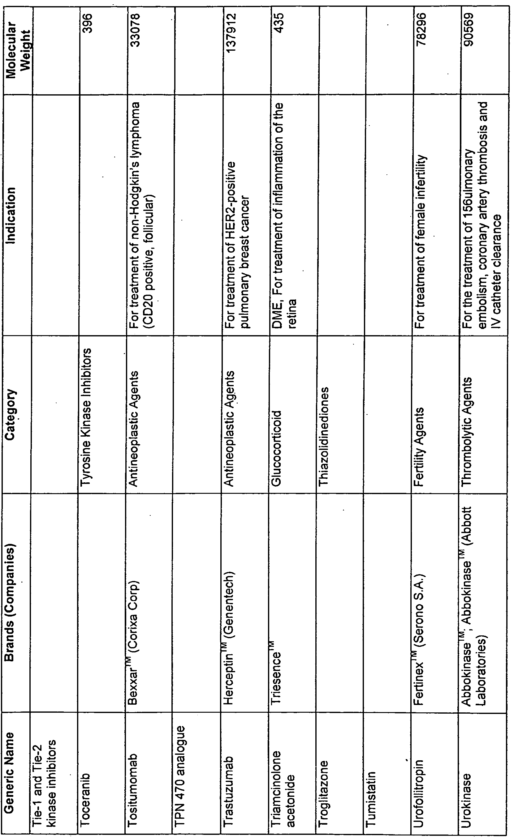

Claims


Priority Applications (7)
| Application Number | Priority Date | Filing Date | Title |
|---|---|---|---|
| JP2013523372A JP6111194B2 (en) | 2010-08-05 | 2011-08-05 | Combination drug delivery method and apparatus |
| EP20110815389 EP2600876B1 (en) | 2010-08-05 | 2011-08-05 | Combined drug delivery methods and apparatus |
| US13/814,466 US10617557B2 (en) | 2010-08-05 | 2011-08-05 | Combined drug delivery methods and apparatus |
| CN201180048624.5A CN103153316B (en) | 2010-08-05 | 2011-08-05 | Composition of medicine delivering method and equipment |
| CA2807537A CA2807537C (en) | 2010-08-05 | 2011-08-05 | Combined drug delivery methods and apparatus |
| AU2011285548A AU2011285548B2 (en) | 2010-08-05 | 2011-08-05 | Combined drug delivery methods and apparatus |
| US16/808,784 US11679027B2 (en) | 2010-08-05 | 2020-03-04 | Combined drug delivery methods and apparatus |
Applications Claiming Priority (2)
| Application Number | Priority Date | Filing Date | Title |
|---|---|---|---|
| US37116810P | 2010-08-05 | 2010-08-05 | |
| US61/371,168 | 2010-08-05 |
Related Child Applications (2)
| Application Number | Title | Priority Date | Filing Date |
|---|---|---|---|
| US13/814,466 A-371-Of-International US10617557B2 (en) | 2010-08-05 | 2011-08-05 | Combined drug delivery methods and apparatus |
| US16/808,784 Continuation US11679027B2 (en) | 2010-08-05 | 2020-03-04 | Combined drug delivery methods and apparatus |
Publications (2)
| Publication Number | Publication Date |
|---|---|
| WO2012019139A1 true WO2012019139A1 (en) | 2012-02-09 |
| WO2012019139A9 WO2012019139A9 (en) | 2013-03-28 |
Family
ID=45559845
Family Applications (1)
| Application Number | Title | Priority Date | Filing Date |
|---|---|---|---|
| PCT/US2011/046817 WO2012019139A1 (en) | 2010-08-05 | 2011-08-05 | Combined drug delivery methods and apparatus |
Country Status (7)
| Country | Link |
|---|---|
| US (2) | US10617557B2 (en) |
| EP (1) | EP2600876B1 (en) |
| JP (1) | JP6111194B2 (en) |
| CN (1) | CN103153316B (en) |
| AU (1) | AU2011285548B2 (en) |
| CA (1) | CA2807537C (en) |
| WO (1) | WO2012019139A1 (en) |
Cited By (7)
| Publication number | Priority date | Publication date | Assignee | Title |
|---|---|---|---|---|
| WO2017035408A1 (en) | 2015-08-26 | 2017-03-02 | Achillion Pharmaceuticals, Inc. | Compounds for treatment of immune and inflammatory disorders |
| WO2018005552A1 (en) | 2016-06-27 | 2018-01-04 | Achillion Pharmaceuticals, Inc. | Quinazoline and indole compounds to treat medical disorders |
| EP3157479A4 (en) * | 2014-06-19 | 2018-03-07 | California Institute of Technology | Small molecule transport device for drug delivery or waste removal |
| WO2019191112A1 (en) | 2018-03-26 | 2019-10-03 | C4 Therapeutics, Inc. | Cereblon binders for the degradation of ikaros |
| WO2020081723A1 (en) | 2018-10-16 | 2020-04-23 | Georgia State University Research Foundation, Inc. | Carbon monoxide prodrugs for the treatment of medical disorders |
| EP4053117A1 (en) | 2015-08-26 | 2022-09-07 | Achillion Pharmaceuticals, Inc. | Aryl, heteroaryl, and heterocyclic compounds for treatment of medical disorders |
| EP4005639A4 (en) * | 2019-07-26 | 2023-09-06 | Tohoku University | Continual drug release device that can be replenished with drugs |
Families Citing this family (21)
| Publication number | Priority date | Publication date | Assignee | Title |
|---|---|---|---|---|
| US8623395B2 (en) | 2010-01-29 | 2014-01-07 | Forsight Vision4, Inc. | Implantable therapeutic device |
| US10617557B2 (en) | 2010-08-05 | 2020-04-14 | Forsight Vision4, Inc. | Combined drug delivery methods and apparatus |
| RS61601B1 (en) | 2010-08-05 | 2021-04-29 | Forsight Vision4 Inc | Injector apparatus for drug delivery |
| US20140031769A1 (en) | 2010-11-19 | 2014-01-30 | Forsight Vision4, Inc. | Therapeutic agent formulations for implanted devices |
| EP2726016B1 (en) | 2011-06-28 | 2023-07-19 | ForSight Vision4, Inc. | An apparatus for collecting a sample of fluid from a reservoir chamber of a therapeutic device for the eye |
| RS61758B1 (en) | 2011-09-16 | 2021-05-31 | Forsight Vision4 Inc | Fluid exchange apparatus |
| US10010448B2 (en) | 2012-02-03 | 2018-07-03 | Forsight Vision4, Inc. | Insertion and removal methods and apparatus for therapeutic devices |
| EP2968113B8 (en) * | 2013-03-14 | 2020-10-28 | Forsight Vision4, Inc. | Systems for sustained intraocular delivery of low solubility compounds from a port delivery system implant |
| CA2907681C (en) | 2013-03-28 | 2022-11-22 | Forsight Vision4, Inc. | Ophthalmic implant for delivering therapeutic substances |
| RU2695563C2 (en) | 2014-07-15 | 2019-07-24 | Форсайт Вижн4, Инк. | Method and device for eye implant delivery |
| WO2016022750A1 (en) | 2014-08-08 | 2016-02-11 | Forsight Vision4, Inc. | Stable and soluble formulations of receptor tyrosine kinase inhibitors, and methods of preparation thereof |
| US10507101B2 (en) | 2014-10-13 | 2019-12-17 | W. L. Gore & Associates, Inc. | Valved conduit |
| JP7037360B2 (en) | 2014-11-10 | 2022-03-16 | フォーサイト・ビジョン フォー・インコーポレーテッド | Expandable drug delivery device |
| US10842916B2 (en) * | 2015-06-24 | 2020-11-24 | Healionics Corporation | Injectable porous device for treatment of dry and wet age-related macular degeneration or diabetic retinopathy |
| WO2017058774A1 (en) * | 2015-09-29 | 2017-04-06 | The Regents Of The University Of California | Methods of diagnosing diseases of mucosal surfaces |
| WO2017087902A1 (en) | 2015-11-20 | 2017-05-26 | Forsight Vision4, Inc. | Porous structures for extended release drug delivery devices |
| MX2018012021A (en) | 2016-04-05 | 2019-01-24 | Forsight Vision4 Inc | Implantable ocular drug delivery devices. |
| US11523940B2 (en) | 2017-03-17 | 2022-12-13 | W. L. Gore & Associates, Inc. | Delivery aids for glaucoma shunts |
| IL308120A (en) | 2017-06-14 | 2023-12-01 | Vertex Pharma | Devices and methods for delivering therapeutics |
| BR112020010053A2 (en) | 2017-11-21 | 2020-11-03 | Forsight Vision4, Inc. | fluid change device for expandable door release system and methods of using it |
| US11678983B2 (en) | 2018-12-12 | 2023-06-20 | W. L. Gore & Associates, Inc. | Implantable component with socket |
Citations (5)
| Publication number | Priority date | Publication date | Assignee | Title |
|---|---|---|---|---|
| US20090074786A1 (en) * | 2005-02-09 | 2009-03-19 | Macusight, Inc. | Formulations for treating ocular diseases and conditions |
| US20090306025A1 (en) * | 2008-05-30 | 2009-12-10 | Fairfield Clinical Trials, Llc | Method and composition for skin inflammation and discoloration |
| US20090318545A1 (en) * | 2008-06-09 | 2009-12-24 | Cornell Reasearch Foundation, Inc. | Mast cell inhibition in diseases of the retina and vitreous |
| US20100189765A1 (en) * | 2008-11-26 | 2010-07-29 | Erickson Signe R | Implantable ocular drug delivery device and methods |
| WO2010088548A1 (en) | 2009-01-29 | 2010-08-05 | Forsight Labs, Llc | Posterior segment drug delivery |
Family Cites Families (387)
| Publication number | Priority date | Publication date | Assignee | Title |
|---|---|---|---|---|
| US2585815A (en) | 1947-01-16 | 1952-02-12 | Mclintock Duncan Menzies | Injection syringe |
| US2564977A (en) | 1949-01-19 | 1951-08-21 | Hu Quang Hsi | Medical injecting apparatus |
| US2886497A (en) | 1957-04-12 | 1959-05-12 | United States Steel Corp | Method for determining the permeability of steel to hydrogen |
| US3232117A (en) | 1962-09-14 | 1966-02-01 | Roger Gilmont Instr Inc | Micrometer buret |
| US3416530A (en) | 1966-03-02 | 1968-12-17 | Richard A. Ness | Eyeball medication dispensing tablet |
| US3618604A (en) | 1969-06-09 | 1971-11-09 | Alza Corp | Ocular insert |
| US3641237A (en) | 1970-09-30 | 1972-02-08 | Nat Patent Dev Corp | Zero order release constant elution rate drug dosage |
| US4034756A (en) | 1971-01-13 | 1977-07-12 | Alza Corporation | Osmotically driven fluid dispenser |
| US3831583A (en) | 1971-03-05 | 1974-08-27 | Univ California | Implantable bulb for inflation of surgical implements |
| US3995635A (en) | 1971-09-09 | 1976-12-07 | Alza Corporation | Ocular insert |
| US3828777A (en) | 1971-11-08 | 1974-08-13 | Alza Corp | Microporous ocular device |
| US3845201A (en) | 1972-04-24 | 1974-10-29 | S Loucas | Solid state ophthalmic medication delivery method |
| US3916899A (en) | 1973-04-25 | 1975-11-04 | Alza Corp | Osmotic dispensing device with maximum and minimum sizes for the passageway |
| US3914402A (en) | 1973-06-14 | 1975-10-21 | Alza Corp | Ophthalmic dosage form, for releasing medication over time |
| US4179497A (en) | 1973-12-17 | 1979-12-18 | Merck & Co., Inc. | Solid state ophthalmic medication |
| US3902495A (en) | 1974-01-28 | 1975-09-02 | Cavitron Corp | Flow control system |
| US3961628A (en) | 1974-04-10 | 1976-06-08 | Alza Corporation | Ocular drug dispensing system |
| US3949748A (en) | 1974-09-26 | 1976-04-13 | Oscar Malmin | Injection syringe having aspirating and metering capabilities |
| US3949750A (en) | 1974-10-07 | 1976-04-13 | Freeman Jerre M | Punctum plug and method for treating keratoconjunctivitis sicca (dry eye) and other ophthalmic aliments using same |
| US3926188A (en) | 1974-11-14 | 1975-12-16 | Alza Corp | Laminated drug dispenser |
| US4096238A (en) | 1974-12-23 | 1978-06-20 | Alza Corporation | Method for administering drug to the gastrointestinal tract |
| US4014335A (en) | 1975-04-21 | 1977-03-29 | Alza Corporation | Ocular drug delivery device |
| NL188266C (en) | 1975-07-29 | 1992-05-18 | Merck & Co Inc | PROCESS FOR THE PREPARATION OF AN ORGANIC IMPLANT. |
| US3977404A (en) | 1975-09-08 | 1976-08-31 | Alza Corporation | Osmotic device having microporous reservoir |
| US4034758A (en) | 1975-09-08 | 1977-07-12 | Alza Corporation | Osmotic therapeutic system for administering medicament |
| US4014333A (en) | 1975-09-22 | 1977-03-29 | Mcintyre David J | Instrument for aspirating and irrigating during ophthalmic surgery |
| US4077407A (en) | 1975-11-24 | 1978-03-07 | Alza Corporation | Osmotic devices having composite walls |
| US4008719A (en) | 1976-02-02 | 1977-02-22 | Alza Corporation | Osmotic system having laminar arrangement for programming delivery of active agent |
| US4014334A (en) | 1976-02-02 | 1977-03-29 | Alza Corporation | Laminated osmotic system for dispensing beneficial agent |
| US4111201A (en) | 1976-11-22 | 1978-09-05 | Alza Corporation | Osmotic system for delivering selected beneficial agents having varying degrees of solubility |
| US4111203A (en) | 1976-11-22 | 1978-09-05 | Alza Corporation | Osmotic system with means for improving delivery kinetics of system |
| US4160452A (en) | 1977-04-07 | 1979-07-10 | Alza Corporation | Osmotic system having laminated wall comprising semipermeable lamina and microporous lamina |
| US4256108A (en) | 1977-04-07 | 1981-03-17 | Alza Corporation | Microporous-semipermeable laminated osmotic system |
| US4164559A (en) | 1977-09-21 | 1979-08-14 | Cornell Research Foundation, Inc. | Collagen drug delivery device |
| US4186184A (en) | 1977-12-27 | 1980-01-29 | Alza Corporation | Selective administration of drug with ocular therapeutic system |
| US4220152A (en) | 1978-05-08 | 1980-09-02 | Pfizer Inc. | Delivery system |
| US4220153A (en) | 1978-05-08 | 1980-09-02 | Pfizer Inc. | Controlled release delivery system |
| US4200098A (en) | 1978-10-23 | 1980-04-29 | Alza Corporation | Osmotic system with distribution zone for dispensing beneficial agent |
| US4298000A (en) | 1978-11-08 | 1981-11-03 | Minnesota Mining And Manufacturing Company | Fluid dispensing device |
| US4300557A (en) | 1980-01-07 | 1981-11-17 | The United States Of America As Represented By The Secretary Of The Department Of Health And Human Services | Method for treating intraocular malignancies |
| DE3068986D1 (en) | 1980-01-28 | 1984-09-27 | Merck & Co Inc | Ophthalmic inserts for lowering intraocular pressure comprising carbonic anhydrase inhibitors |
| US4309776A (en) | 1980-05-13 | 1982-01-12 | Ramon Berguer | Intravascular implantation device and method of using the same |
| US4326525A (en) | 1980-10-14 | 1982-04-27 | Alza Corporation | Osmotic device that improves delivery properties of agent in situ |
| US4327725A (en) | 1980-11-25 | 1982-05-04 | Alza Corporation | Osmotic device with hydrogel driving member |
| US4484922A (en) | 1981-06-25 | 1984-11-27 | Rosenwald Peter L | Occular device |
| US4439198A (en) | 1981-07-09 | 1984-03-27 | University Of Illinois Foundation | Biodegradable ocular insert for controlled delivery of ophthalmic medication |
| US4730013A (en) | 1981-10-08 | 1988-03-08 | Merck & Co., Inc. | Biosoluble ocular insert |
| US4475916A (en) | 1982-03-18 | 1984-10-09 | Merck & Co., Inc. | Osmotic drug delivery system |
| US4439196A (en) | 1982-03-18 | 1984-03-27 | Merck & Co., Inc. | Osmotic drug delivery system |
| US4519801A (en) | 1982-07-12 | 1985-05-28 | Alza Corporation | Osmotic device with wall comprising cellulose ether and permeability enhancer |
| US4673405A (en) | 1983-03-04 | 1987-06-16 | Alza Corporation | Osmotic system with instant drug availability |
| US4883459A (en) | 1983-07-29 | 1989-11-28 | Reynaldo Calderon | Retrograde perfusion |
| US4774091A (en) | 1983-10-14 | 1988-09-27 | Sumitomo Pharmaceuticals Company, Ltd. | Long-term sustained-release preparation |
| US4627850A (en) | 1983-11-02 | 1986-12-09 | Alza Corporation | Osmotic capsule |
| US4777049A (en) | 1983-12-01 | 1988-10-11 | Alza Corporation | Constant release system with pulsed release |
| US4634418A (en) | 1984-04-06 | 1987-01-06 | Binder Perry S | Hydrogel seton |
| US4851228A (en) | 1984-06-20 | 1989-07-25 | Merck & Co., Inc. | Multiparticulate controlled porosity osmotic |
| US4634427A (en) | 1984-09-04 | 1987-01-06 | American Hospital Supply Company | Implantable demand medication delivery assembly |
| US5049142A (en) | 1984-11-07 | 1991-09-17 | Herrick Robert S | Intracanalicular implant for horizontal canalicular blockade treatment of the eye |
| US5053030A (en) | 1984-11-07 | 1991-10-01 | Herrick Robert S | Intracanalicular implant for horizontal canalicular blockade treatment of the eye |
| US4712550A (en) | 1985-04-08 | 1987-12-15 | Sinnett Kevin B | Retinal tack |
| US4693886A (en) | 1985-04-22 | 1987-09-15 | Alza Corporation | Osmotic device with inert core |
| US4609374A (en) | 1985-04-22 | 1986-09-02 | Alza Corporation | Osmotic device comprising means for governing initial time of agent release therefrom |
| EP0201611A1 (en) | 1985-05-10 | 1986-11-20 | B. Braun-SSC AG | Two cannulae syringe |
| EP0228185B1 (en) | 1985-11-27 | 1990-07-25 | Thomas C. White | Tissue-implantable fluid-dissipating device |
| US4781675A (en) | 1985-11-27 | 1988-11-01 | White Thomas C | Infusion cannula |
| US4959217A (en) | 1986-05-22 | 1990-09-25 | Syntex (U.S.A.) Inc. | Delayed/sustained release of macromolecules |
| US5147647A (en) | 1986-10-02 | 1992-09-15 | Sohrab Darougar | Ocular insert for the fornix |
| US5322691A (en) | 1986-10-02 | 1994-06-21 | Sohrab Darougar | Ocular insert with anchoring protrusions |
| US4863457A (en) | 1986-11-24 | 1989-09-05 | Lee David A | Drug delivery device |
| AU609711B2 (en) | 1986-12-23 | 1991-05-09 | Liposome Company, Inc., The | Liposome preparation and antibiotic |
| US4853229A (en) | 1987-10-26 | 1989-08-01 | Alza Corporation | Method for adminstering tiny pills |
| JP2702953B2 (en) | 1988-01-30 | 1998-01-26 | オリンパス光学工業株式会社 | Chemical impregnated ceramics |
| US4865846A (en) | 1988-06-03 | 1989-09-12 | Kaufman Herbert E | Drug delivery system |
| US5174999A (en) | 1988-12-13 | 1992-12-29 | Alza Corporation | Delivery system comprising fluid ingress and drug egress |
| AU4951690A (en) | 1988-12-30 | 1990-08-01 | David M. Anderson | Stabilized microporous materials and hydrogel materials |
| US5141748A (en) | 1989-02-17 | 1992-08-25 | Hoffmann-La Roche, Inc. | Implant drug delivery device |
| US5098443A (en) | 1989-03-23 | 1992-03-24 | University Of Miami | Method of implanting intraocular and intraorbital implantable devices for the controlled release of pharmacological agents |
| US4979938A (en) | 1989-05-11 | 1990-12-25 | Iomed, Inc. | Method of iontophoretically treating acne, furuncles and like skin disorders |
| US5164188A (en) | 1989-11-22 | 1992-11-17 | Visionex, Inc. | Biodegradable ocular implants |
| US5171270A (en) | 1990-03-29 | 1992-12-15 | Herrick Robert S | Canalicular implant having a collapsible flared section and method |
| US5324280A (en) | 1990-04-02 | 1994-06-28 | Alza Corporation | Osmotic dosage system for delivering a formulation comprising liquid carrier and drug |
| US5128145A (en) | 1990-06-13 | 1992-07-07 | Alza Corporation | Dosage form for Parkinson's disease, spasticity and muscle spasms |
| US5238687A (en) | 1990-07-11 | 1993-08-24 | Alza Corporation | Delivery device with a protective sleeve |
| US5084021A (en) | 1990-11-02 | 1992-01-28 | Baldwin Brian E | Patient controlled infusion apparatus and method |
| US5378475A (en) | 1991-02-21 | 1995-01-03 | University Of Kentucky Research Foundation | Sustained release drug delivery devices |
| AU650113B2 (en) | 1991-04-05 | 1994-06-09 | Eli Lilly And Company | Sustained release capsule and formulations |
| US5334189A (en) | 1991-06-03 | 1994-08-02 | Wade Stephen E | Device for controlled diffusion of a chemical substance |
| US5282829A (en) | 1991-08-15 | 1994-02-01 | United States Surgical Corporation | Hollow body implants |
| FR2682090B1 (en) | 1991-10-03 | 1993-12-31 | Holzstoff Holding Sa | RESERVOIR SYSTEM FOR EXTENDED BROADCASTING OF AN ACTIVE INGREDIENT. |
| US5681572A (en) | 1991-10-18 | 1997-10-28 | Seare, Jr.; William J. | Porous material product and process |
| US5178635A (en) | 1992-05-04 | 1993-01-12 | Allergan, Inc. | Method for determining amount of medication in an implantable device |
| US6096756A (en) | 1992-09-21 | 2000-08-01 | Albert Einstein College Of Medicine Of Yeshiva University | Method of simultaneously enhancing analgesic potency and attenuating dependence liability caused by morphine and other bimodally-acting opioid agonists |
| US5336175A (en) | 1992-10-29 | 1994-08-09 | Mames Robert N | Method for the treatment of retinal detachments |
| US5443505A (en) | 1993-11-15 | 1995-08-22 | Oculex Pharmaceuticals, Inc. | Biocompatible ocular implants |
| CA2140053C (en) | 1994-02-09 | 2000-04-04 | Joel S. Rosenblatt | Collagen-based injectable drug delivery system and its use |
| US5985328A (en) | 1994-03-07 | 1999-11-16 | Regents Of The University Of California | Micromachined porous membranes with bulk support |
| US5770076A (en) | 1994-03-07 | 1998-06-23 | The Regents Of The University Of California | Micromachined capsules having porous membranes and bulk supports |
| US5578042A (en) | 1994-03-14 | 1996-11-26 | Cumming; J. Stuart | Ophthalmic kit and method for lens insertion |
| US5466233A (en) | 1994-04-25 | 1995-11-14 | Escalon Ophthalmics, Inc. | Tack for intraocular drug delivery and method for inserting and removing same |
| AUPM897594A0 (en) | 1994-10-25 | 1994-11-17 | Daratech Pty Ltd | Controlled release container |
| ATE232089T1 (en) | 1994-11-10 | 2003-02-15 | Univ Kentucky Res Found | CONTROLLED RELEASE IMPLANTABLE REFILLABLE DEVICE FOR ADMINISTERING DRUGS IMMEDIATELY TO AN INTERNAL PART OF THE BODY |
| US5725493A (en) | 1994-12-12 | 1998-03-10 | Avery; Robert Logan | Intravitreal medicine delivery |
| US5554132A (en) | 1995-03-30 | 1996-09-10 | Abbott Laboratories | Hand grip for use with syringe |
| IL113723A (en) | 1995-05-14 | 2002-11-10 | Optonol Ltd | Intraocular implant |
| US6685940B2 (en) | 1995-07-27 | 2004-02-03 | Genentech, Inc. | Protein formulation |
| US5773019A (en) | 1995-09-27 | 1998-06-30 | The University Of Kentucky Research Foundation | Implantable controlled release device to deliver drugs directly to an internal portion of the body |
| US6641708B1 (en) | 1996-01-31 | 2003-11-04 | Board Of Regents, The University Of Texas System | Method and apparatus for fractionation using conventional dielectrophoresis and field flow fractionation |
| GB2310149A (en) | 1996-02-15 | 1997-08-20 | Nomix Chipman Ltd | Spray gun |
| US20090005864A1 (en) | 1996-03-18 | 2009-01-01 | Eggleston Harry C | Modular intraocular implant |
| US5951512A (en) | 1996-05-28 | 1999-09-14 | Horizon Medical Products, Inc. | Infusion port with modified drug reservoir |
| US5797898A (en) | 1996-07-02 | 1998-08-25 | Massachusetts Institute Of Technology | Microchip drug delivery devices |
| US5928662A (en) | 1996-07-31 | 1999-07-27 | Phillips; Andrew F. | Ocular drug delivery device |
| AU7533696A (en) | 1996-12-13 | 1998-06-18 | Ciba-Geigy Ag | New materials |
| DE69816980T2 (en) | 1997-03-31 | 2004-07-22 | Alza Corp., Palo Alto | IMPLANTABLE DIFFUSION DELIVERY SYSTEM |
| US7160687B1 (en) | 1997-05-29 | 2007-01-09 | Cellomics, Inc. | Miniaturized cell array methods and apparatus for cell-based screening |
| US5968008A (en) | 1997-08-04 | 1999-10-19 | Grams; Guenter A. | Cannula with parallel channels and sliding sheath |
| US5902598A (en) | 1997-08-28 | 1999-05-11 | Control Delivery Systems, Inc. | Sustained release drug delivery devices |
| US6331523B1 (en) | 1998-03-12 | 2001-12-18 | Genentech, Inc. | Method of enhancing the survival of retinal neurons and treating ocular diseases using FGF-5 |
| US6196993B1 (en) | 1998-04-20 | 2001-03-06 | Eyelab Group, Llc | Ophthalmic insert and method for sustained release of medication to the eye |
| FR2784296B1 (en) | 1998-09-18 | 2001-01-05 | Imedex Biomateriaux | DEVICE FOR FORMULATING AND DELIVERING A MIXTURE, PARTICULARLY FOR THE SURGICAL APPLICATION OF THIS MIXTURE |
| US7973068B2 (en) | 1998-10-20 | 2011-07-05 | Omeros Corporation | Arthroscopic irrigation solution and method for peripheral vasoconstriction and inhibition of pain and inflammation |
| DE19948783C2 (en) | 1999-02-18 | 2001-06-13 | Alcove Surfaces Gmbh | Implant |
| US7914442B1 (en) | 1999-03-01 | 2011-03-29 | Gazdzinski Robert F | Endoscopic smart probe and method |
| US20050119601A9 (en) * | 1999-04-26 | 2005-06-02 | Lynch Mary G. | Shunt device and method for treating glaucoma |
| US6395300B1 (en) | 1999-05-27 | 2002-05-28 | Acusphere, Inc. | Porous drug matrices and methods of manufacture thereof |
| US6472162B1 (en) | 1999-06-04 | 2002-10-29 | Thermogenesis Corp. | Method for preparing thrombin for use in a biological glue |
| ATE260660T1 (en) | 1999-06-18 | 2004-03-15 | Alcon Mfg Ltd | METHOD FOR DETERMINING THE CONCENTRATION OF AN AMPHIPATHIC ANTHISTAMINIC COMPOUND BY DETERMINING ITS SURFACE ACTIVITY CLASSIFICATION |
| US6638263B1 (en) | 1999-10-12 | 2003-10-28 | Durect Corporation | Regulation of drug delivery through flow diversion |
| US6416777B1 (en) | 1999-10-21 | 2002-07-09 | Alcon Universal Ltd. | Ophthalmic drug delivery device |
| US6413245B1 (en) * | 1999-10-21 | 2002-07-02 | Alcon Universal Ltd. | Sub-tenon drug delivery |
| DE60016271T2 (en) | 1999-10-21 | 2005-12-01 | Alcon Inc. | drug delivery |
| US6331313B1 (en) | 1999-10-22 | 2001-12-18 | Oculex Pharmaceticals, Inc. | Controlled-release biocompatible ocular drug delivery implant devices and methods |
| US20030212383A1 (en) | 2001-01-05 | 2003-11-13 | Dana Cote | System and methods for reducing intraocular pressure |
| JP4290915B2 (en) | 2000-01-12 | 2009-07-08 | ベクトン・ディキンソン・アンド・カンパニー | System and method for reducing intraocular pressure |
| US20050119737A1 (en) | 2000-01-12 | 2005-06-02 | Bene Eric A. | Ocular implant and methods for making and using same |
| DE10008826C2 (en) | 2000-02-25 | 2002-03-14 | Disetronic Licensing Ag | Micro perfusion device with collection container |
| US7077848B1 (en) | 2000-03-11 | 2006-07-18 | John Hopkins University | Sutureless occular surgical methods and instruments for use in such methods |
| US7169444B2 (en) | 2000-03-13 | 2007-01-30 | Seiko Epson Corporation | Method for treating surface of ink jet recording medium having recorded image |
| US7141152B2 (en) | 2000-03-16 | 2006-11-28 | Le Febre David A | Analyte species separation system |
| US6375972B1 (en) | 2000-04-26 | 2002-04-23 | Control Delivery Systems, Inc. | Sustained release drug delivery devices, methods of use, and methods of manufacturing thereof |
| DE60135352D1 (en) * | 2000-08-30 | 2008-09-25 | Univ Johns Hopkins | DEVICE FOR INTRA-OCCULAR ACTIVE AGGREGATION |
| PT1337284E (en) | 2000-09-06 | 2007-12-26 | Alcon Inc | Switchable tackiness coating compositions for ophthalmic implants |
| US6303290B1 (en) | 2000-09-13 | 2001-10-16 | The Trustees Of The University Of Pennsylvania | Encapsulation of biomaterials in porous glass-like matrices prepared via an aqueous colloidal sol-gel process |
| WO2002056863A2 (en) | 2000-12-29 | 2002-07-25 | Bausch & Lomb Incorporated | Sustained release drug delivery devices |
| CA2432225C (en) | 2001-01-03 | 2008-01-15 | Michael J. Brubaker | Sustained release drug delivery devices with prefabricated permeable plugs |
| CA2432203C (en) | 2001-01-03 | 2008-03-25 | Michael J. Brubaker | Sustained release drug delivery devices with multiple agents |
| ES2294043T3 (en) | 2001-01-03 | 2008-04-01 | BAUSCH & LOMB INCORPORATED | PROLONGED RELEASE DEVICES OF MEDICINES THAT INCLUDE NUCLEOS COVERED MEDICINES. |
| WO2002055058A2 (en) | 2001-01-09 | 2002-07-18 | Microchips, Inc. | Flexible microchip devices for ophthalmic and other applications |
| US6872198B1 (en) | 2001-01-24 | 2005-03-29 | Arrow International, Inc. | Double-y-shaped multi-lumen catheter with selectively attachable hubs |
| WO2002058667A2 (en) | 2001-01-26 | 2002-08-01 | Bausch & Lomb Incorporated | Improved process for the production of sustained release drug delivery devices |
| US7181287B2 (en) | 2001-02-13 | 2007-02-20 | Second Sight Medical Products, Inc. | Implantable drug delivery device |
| FR2821672B1 (en) | 2001-03-02 | 2003-05-02 | Scp Dosagene R & D | MEANS FOR THE EXTRACTION OF PRODUCTS TO BE ANALYZED AND THEIR APPLICATIONS IN DIAGNOSIS AND ANALYSIS |
| US6713081B2 (en) | 2001-03-15 | 2004-03-30 | The United States Of America As Represented By The Department Of Health And Human Services | Ocular therapeutic agent delivery devices and methods for making and using such devices |
| DE60239868D1 (en) | 2001-06-12 | 2011-06-09 | Univ Johns Hopkins Med | RESERVOIR DEVICE FOR INTRAOCULAR DRUG DELIVERY |
| EP1414416A4 (en) | 2001-07-10 | 2007-06-27 | Teva Pharma | Drug delivery system for zero order, zero order-biphasic, ascending or descending drug delivery |
| IL144446A0 (en) | 2001-07-19 | 2002-05-23 | Prochon Biotech Ltd | Plasma protein matrices and methods for their preparation |
| WO2003009774A2 (en) | 2001-07-23 | 2003-02-06 | Alcon, Inc. | Ophthalmic drug delivery device |
| JP4249611B2 (en) | 2001-07-23 | 2009-04-02 | アルコン,インコーポレイティド | Ophthalmic drug delivery device |
| JP2005501602A (en) | 2001-08-29 | 2005-01-20 | カルバーリョ、リカルド エイ.ピー. デ | Sealable implantable device for unidirectional delivery of therapeutic agents to tissue |
| US7749528B2 (en) | 2001-08-29 | 2010-07-06 | Ricardo Azevedo Pontes De Carvalho | Implantable and sealable medical device for unidirectional delivery of therapeutic agents to tissues |
| WO2003028765A1 (en) | 2001-09-28 | 2003-04-10 | Santen Pharmaceutical Co., Ltd. | Injections for eye tissue containing drug bound to polyethylene glycol |
| US20030118649A1 (en) | 2001-10-04 | 2003-06-26 | Jinming Gao | Drug delivery devices and methods |
| US8663687B2 (en) | 2001-10-12 | 2014-03-04 | Monosol Rx, Llc | Film compositions for delivery of actives |
| AU2002352746A1 (en) | 2001-11-15 | 2003-06-10 | Arryx, Inc. | Sample chip |
| CA2473355C (en) | 2002-01-18 | 2012-01-03 | Michael E. Snyder | Sustained release ophthalmological device and method of making and using the same |
| US8364229B2 (en) | 2003-07-25 | 2013-01-29 | Dexcom, Inc. | Analyte sensors having a signal-to-noise ratio substantially unaffected by non-constant noise |
| CN1638743B (en) | 2002-03-11 | 2012-11-07 | 爱尔康公司 | Implantable drug delivery system |
| US7074426B2 (en) | 2002-03-27 | 2006-07-11 | Frank Kochinke | Methods and drug delivery systems for the treatment of orofacial diseases |
| US7968569B2 (en) | 2002-05-17 | 2011-06-28 | Celgene Corporation | Methods for treatment of multiple myeloma using 3-(4-amino-1-oxo-1,3-dihydro-isoindol-2-yl)-piperidine-2,6-dione |
| US7939094B2 (en) | 2002-06-19 | 2011-05-10 | Boston Scientific Scimed, Inc. | Multiphase polymeric drug release region |
| ATE424187T1 (en) | 2002-07-15 | 2009-03-15 | Alcon Inc | BIOERODIBLE FILM FOR DELIVERING AN OPHTHALMIC MEDICINAL PRODUCT |
| US8425549B2 (en) | 2002-07-23 | 2013-04-23 | Reverse Medical Corporation | Systems and methods for removing obstructive matter from body lumens and treating vascular defects |
| US20040019325A1 (en) | 2002-07-29 | 2004-01-29 | Medrip Ltd. | Syringe Pump |
| US7468065B2 (en) | 2002-09-18 | 2008-12-23 | Allergan, Inc. | Apparatus for delivery of ocular implants |
| PL223153B1 (en) | 2002-09-18 | 2016-10-31 | Allergan Inc | Methods and apparatus for delivery of ocular implants |
| US20050143363A1 (en) | 2002-09-29 | 2005-06-30 | Innorx, Inc. | Method for subretinal administration of therapeutics including steroids; method for localizing pharmacodynamic action at the choroid of the retina; and related methods for treatment and/or prevention of retinal diseases |
| WO2004066871A2 (en) | 2003-01-24 | 2004-08-12 | Doheny Retina Institute | Reservoirs with subretinal cannula for subretinal drug delivery |
| US20060167435A1 (en) | 2003-02-18 | 2006-07-27 | Adamis Anthony P | Transscleral drug delivery device and related methods |
| WO2004076647A2 (en) | 2003-02-26 | 2004-09-10 | The Regents Of The University Of California | Use of steady-state oxygen gradients to modulate animal cell functions |
| US20050074497A1 (en) | 2003-04-09 | 2005-04-07 | Schultz Clyde L. | Hydrogels used to deliver medicaments to the eye for the treatment of posterior segment diseases |
| US20050255144A1 (en) | 2003-04-09 | 2005-11-17 | Directcontact Llc | Methods and articles for the delivery of medicaments to the eye for the treatment of posterior segment diseases |
| US7094222B1 (en) | 2003-04-28 | 2006-08-22 | The United States Of America As Represented By The Secretary Of Navy | Syringe device for simultaneous infusion and withdrawal |
| EP1671624B1 (en) | 2003-05-02 | 2010-08-11 | SurModics, Inc. | Delivery device for a controlled drug release of an active agent into the posterior section of the eye |
| EP1633320A2 (en) | 2003-05-02 | 2006-03-15 | SurModics, Inc. | Implantable controlled release bioactive agent delivery device |
| EP1635876A4 (en) | 2003-06-13 | 2009-05-06 | Becton Dickinson Co | Improved intra-dermal delivery of biologically active agents |
| US20040260381A1 (en) | 2003-06-18 | 2004-12-23 | D-Crown Ltd | Devices and methods for forming stenting structures in situ |
| WO2004112653A2 (en) | 2003-06-18 | 2004-12-29 | D-Crown Ltd. | Devices and methods for delivering and forming single and multiple stenting structures in situ |
| US20040260380A1 (en) | 2003-06-18 | 2004-12-23 | D-Crown Ltd | Devices for delivering multiple stenting structures in situ |
| WO2005007233A2 (en) | 2003-06-20 | 2005-01-27 | Massachusetts Institute Of Technology | Application of electrical stimulation for functional tissue engineering in vitro and in vivo |
| JP2007526019A (en) | 2003-07-10 | 2007-09-13 | アルコン,インコーポレイティド | Ophthalmic drug delivery device |
| FI120333B (en) | 2003-08-20 | 2009-09-30 | Bioretec Oy | A porous medical device and a method of making it |
| AU2004274026A1 (en) | 2003-09-18 | 2005-03-31 | Macusight, Inc. | Transscleral delivery |
| US20050181018A1 (en) | 2003-09-19 | 2005-08-18 | Peyman Gholam A. | Ocular drug delivery |
| AU2006225241B2 (en) | 2003-09-24 | 2008-07-17 | Tianda Pharmaceuticals (Australia) Pty Limited | Medication Holder |
| WO2005028006A1 (en) | 2003-09-24 | 2005-03-31 | Medi-Stream Pty Ltd | Medication holder |
| US7615141B2 (en) | 2003-10-03 | 2009-11-10 | University Of Washington | Electrochemical micromanufacturing system and method |
| US7211272B2 (en) | 2003-12-22 | 2007-05-01 | Bausch & Lomb Incorporated | Drug delivery device |
| JP4602356B2 (en) | 2004-02-12 | 2010-12-22 | ネオビスタ、インコーポレイテッド | Method and apparatus for intraocular brachytherapy |
| US7276050B2 (en) | 2004-03-02 | 2007-10-02 | Alan Franklin | Trans-scleral drug delivery method and apparatus |
| WO2005091922A2 (en) | 2004-03-03 | 2005-10-06 | Becton, Dickinson And Company | Methods and devices for improving delivery of a substance to skin |
| US8685435B2 (en) | 2004-04-30 | 2014-04-01 | Allergan, Inc. | Extended release biodegradable ocular implants |
| US20050244472A1 (en) | 2004-04-30 | 2005-11-03 | Allergan, Inc. | Intraocular drug delivery systems containing excipients with reduced toxicity and related methods |
| US20070059336A1 (en) | 2004-04-30 | 2007-03-15 | Allergan, Inc. | Anti-angiogenic sustained release intraocular implants and related methods |
| US20060182783A1 (en) | 2004-04-30 | 2006-08-17 | Allergan, Inc. | Sustained release intraocular drug delivery systems |
| US8591885B2 (en) | 2004-04-30 | 2013-11-26 | Allergan, Inc. | Carbonic anhydrase inhibitor sustained release intraocular drug delivery systems |
| US20050244469A1 (en) | 2004-04-30 | 2005-11-03 | Allergan, Inc. | Extended therapeutic effect ocular implant treatments |
| WO2006014484A2 (en) | 2004-07-02 | 2006-02-09 | Surmodics, Inc. | Methods and devices for the treatment of ocular conditions |
| US7117870B2 (en) | 2004-07-26 | 2006-10-10 | Clarity Corporation | Lacrimal insert having reservoir with controlled release of medication and method of manufacturing the same |
| WO2006013376A2 (en) * | 2004-08-04 | 2006-02-09 | Biocompatibles Uk Limited | Drug delivery of a cox inhibitor from embolic agents |
| WO2006015385A2 (en) | 2004-08-06 | 2006-02-09 | Sopherion Therapeutics, Inc. | Anti-angiogenic peptides and methods of use thereof |
| WO2006031358A2 (en) | 2004-08-13 | 2006-03-23 | Hyperbranch Medical Technology, Inc. | Dendritic polymers, crosslinked gels, and their uses as ophthalmic sealants and lenses |
| US20060104969A1 (en) | 2004-08-16 | 2006-05-18 | Massachusetts Institute Of Technology | Compositions and methods for enhancing structural and functional nervous system reorganization and recovery |
| WO2006031388A2 (en) | 2004-08-20 | 2006-03-23 | Hyperbranch Medical Technology, Inc. | Dentritic polymers, crosslinked gels, and their uses in orthopedic applications |
| US20060052754A1 (en) | 2004-09-04 | 2006-03-09 | Fields Douglas W | Thumb trigger syringe pole |
| WO2006031532A2 (en) | 2004-09-10 | 2006-03-23 | Surmodics, Inc. | Methods, devices, and coatings for controlled active agent release |
| JP5682991B2 (en) | 2004-10-01 | 2015-03-11 | ラムズコア, インコーポレイテッド | Convenient implantable sustained release drug formulation |
| US20080038316A1 (en) | 2004-10-01 | 2008-02-14 | Wong Vernon G | Conveniently implantable sustained release drug compositions |
| EP1812030A4 (en) | 2004-10-14 | 2009-01-14 | Sopherion Therapeutics Inc | Anti-angiogenic peptides and methods of use thereof |
| JO3000B1 (en) | 2004-10-20 | 2016-09-05 | Genentech Inc | Antibody Formulations. |
| US20090208556A1 (en) | 2004-10-29 | 2009-08-20 | Regents Of The University Of California, The | Porous photonic crystals for drug delivery to the eye |
| US20060129215A1 (en) | 2004-12-09 | 2006-06-15 | Helmus Michael N | Medical devices having nanostructured regions for controlled tissue biocompatibility and drug delivery |
| US20060154981A1 (en) | 2005-01-12 | 2006-07-13 | Alcon, Inc. | Method of reducing intraocular pressure and treating glaucoma |
| US20080233053A1 (en) | 2005-02-07 | 2008-09-25 | Pharmalight Inc. | Method and Device for Ophthalmic Administration of Active Pharmaceutical Ingredients |
| US20060233858A1 (en) | 2005-03-08 | 2006-10-19 | Allergan, Inc. | Systems and methods providing targeted intraocular drug delivery |
| EP1871366A2 (en) | 2005-03-21 | 2008-01-02 | Macusight, Inc. | Drug delivery systems for treatment of diseases or conditions |
| US20070077270A1 (en) | 2005-03-28 | 2007-04-05 | Clemson University | Delivery devices and methods for long-term, targeted delivery of therapeutic agents to the eye and ear |
| US20070066138A1 (en) | 2005-04-05 | 2007-03-22 | The Ohio State University Research Foundation | Diffusion Delivery Systems and Methods of Fabrication |
| US20060228390A1 (en) * | 2005-04-07 | 2006-10-12 | Williams David F | Intravitreal implant |
| US20100168535A1 (en) | 2006-04-12 | 2010-07-01 | Mark Ries Robinson | Methods and apparatuses related to blood analyte measurement system |
| US20060258994A1 (en) | 2005-05-12 | 2006-11-16 | Avery Robert L | Implantable delivery device for administering pharmacological agents to an internal portion of a body |
| WO2006127962A2 (en) | 2005-05-25 | 2006-11-30 | Becton, Dickinson And Comapny | Particulate formulations for intradermal delivery of biologically active agents |
| KR20080043763A (en) | 2005-06-17 | 2008-05-19 | 다이나미스 테라퓨틱스, 인코포레이티드 | Treatment of inflammatory conditions |
| US7893040B2 (en) | 2005-07-22 | 2011-02-22 | Oculis Ehf | Cyclodextrin nanotechnology for ophthalmic drug delivery |
| US8663673B2 (en) | 2005-07-29 | 2014-03-04 | Surmodics, Inc. | Devices, articles, coatings, and methods for controlled active agent release or hemocompatibility |
| EP1912574A4 (en) | 2005-08-10 | 2010-08-04 | Insight Instr Inc | Tool for extracting vitreous samples from an eye |
| US20070212397A1 (en) | 2005-09-15 | 2007-09-13 | Roth Daniel B | Pharmaceutical delivery device and method for providing ocular treatment |
| EP1924309A1 (en) | 2005-09-16 | 2008-05-28 | (OSI) Eyetech Inc. | Ophthalmic syringe |
| US20070071756A1 (en) | 2005-09-26 | 2007-03-29 | Peyman Gholam A | Delivery of an agent to ameliorate inflammation |
| US20070072933A1 (en) | 2005-09-26 | 2007-03-29 | Peyman Gholam A | Delivery of an ocular agent |
| WO2007038453A2 (en) | 2005-09-26 | 2007-04-05 | Advanced Ocular Systems Limited | Use of an anti-vascular endothelial growth factor (vegf) agent to ameliorate inflammation |
| US20080167600A1 (en) * | 2005-09-26 | 2008-07-10 | Peyman Gholam A | Device for delivery of an agent to the eye and other sites |
| US20080003219A1 (en) | 2005-09-26 | 2008-01-03 | Minu, L.L.C. | Delivery of an ocular agent |
| TW200732347A (en) | 2005-10-06 | 2007-09-01 | Trophogen Inc | VEGF analogs and methods of use |
| US8168584B2 (en) * | 2005-10-08 | 2012-05-01 | Potentia Pharmaceuticals, Inc. | Methods of treating age-related macular degeneration by compstatin and analogs thereof |
| US20090043253A1 (en) | 2005-10-11 | 2009-02-12 | Blake Podaima | Smart medical compliance method and system |
| US20070197491A1 (en) | 2005-10-14 | 2007-08-23 | Alcon, Inc. | Method for treating primary and secondary forms of glaucoma |
| US20080125406A1 (en) | 2005-10-14 | 2008-05-29 | Robin Alan L | Method for Treating Primary and Secondary Forms of Glaucoma |
| JP4721425B2 (en) | 2005-12-01 | 2011-07-13 | キヤノン株式会社 | Fluid moving method and fluid moving device |
| CN101336315B (en) | 2005-12-07 | 2012-12-19 | 特拉维夫大学拉莫特有限公司 | Drug-delivering composite structures |
| US20070131610A1 (en) | 2005-12-13 | 2007-06-14 | General Electric Company | Membrane-based apparatus and associated method |
| US20070131611A1 (en) | 2005-12-13 | 2007-06-14 | General Electric Company | Membrane-based article and associated method |
| EP3005996B1 (en) | 2006-01-17 | 2019-12-04 | Novartis Ag | Glaucoma treatment device |
| CA2637602C (en) | 2006-01-17 | 2014-09-16 | Forsight Labs, Llc | Drug delivery treatment device |
| US20080216736A1 (en) | 2006-01-19 | 2008-09-11 | Takeda San Diego, Inc. | Microfluidic device with diffusion between adjacent lumens |
| US8979770B2 (en) | 2006-02-24 | 2015-03-17 | Merck Sharp & Dohme Corp. | Extraction and diagnostic fluid devices, systems and methods of use |
| US7625927B2 (en) | 2006-02-27 | 2009-12-01 | Alcon Research, Ltd. | Method of treating glaucoma |
| US20070212388A1 (en) | 2006-03-08 | 2007-09-13 | Sahajanand Medical Technologies Pvt. Ltd. | Compositions comprising porous articles and uses in implantable medical devices |
| TW200800230A (en) | 2006-03-31 | 2008-01-01 | Dynamis Therapeutics Inc | Composition and method related to fructosamine-3-kinase inhibitors |
| EP3449873A1 (en) | 2006-03-31 | 2019-03-06 | Mati Therapeutics Inc. | Drug delivery structures and compositions for nasolacrimal system |
| US7547300B2 (en) | 2006-04-12 | 2009-06-16 | Icu Medical, Inc. | Vial adaptor for regulating pressure |
| EA013662B1 (en) | 2006-04-18 | 2010-06-30 | Чжуншань Ботай Фармасьютик Инструментс Ко., Лтд. | Antiseptic syringe |
| US7918814B2 (en) | 2006-05-02 | 2011-04-05 | Georgia Tech Research Corporation | Method for drug delivery to ocular tissue using microneedle |
| US8197435B2 (en) | 2006-05-02 | 2012-06-12 | Emory University | Methods and devices for drug delivery to ocular tissue using microneedle |
| US7981096B2 (en) | 2006-05-12 | 2011-07-19 | David Castillejos | Optic nerve head implant and medication delivery system |
| US20070270750A1 (en) | 2006-05-17 | 2007-11-22 | Alcon, Inc. | Drug delivery device |
| US20080124372A1 (en) | 2006-06-06 | 2008-05-29 | Hossainy Syed F A | Morphology profiles for control of agent release rates from polymer matrices |
| WO2008003043A2 (en) | 2006-06-28 | 2008-01-03 | Surmodics, Inc. | Combination degradable and non-degradable matrices for active agent delivery |
| TW200815045A (en) | 2006-06-29 | 2008-04-01 | Jazz Pharmaceuticals Inc | Pharmaceutical compositions of ropinirole and methods of use thereof |
| CA2657064C (en) | 2006-07-19 | 2014-09-23 | Noab Biodiscoveries Inc. | Method and device to extract components contained in a fluid |
| JP2009544355A (en) | 2006-07-20 | 2009-12-17 | ニューロシステック コーポレイション | Devices, systems, and methods for ophthalmic drug delivery |
| US20080069854A1 (en) | 2006-08-02 | 2008-03-20 | Inframat Corporation | Medical devices and methods of making and using |
| US9039761B2 (en) | 2006-08-04 | 2015-05-26 | Allergan, Inc. | Ocular implant delivery assemblies with distal caps |
| JP2008054521A (en) | 2006-08-29 | 2008-03-13 | Canon Inc | Cell-culturing device and cell-culturing method |
| US20080057106A1 (en) * | 2006-08-29 | 2008-03-06 | Erickson Signe R | Low profile bioactive agent delivery device |
| WO2008033924A2 (en) | 2006-09-12 | 2008-03-20 | Board Of Regents Of The University Of Nebraska | Methods and compositions for targeted delivery of therapeutic agents |
| US20080066739A1 (en) | 2006-09-20 | 2008-03-20 | Lemahieu Edward | Methods and systems of delivering medication via inhalation |
| US20080089923A1 (en) | 2006-09-29 | 2008-04-17 | Burkstrand Michael J | Biodegradable ocular implants and methods for treating ocular conditions |
| US9149750B2 (en) | 2006-09-29 | 2015-10-06 | Mott Corporation | Sinter bonded porous metallic coatings |
| WO2008045272A2 (en) | 2006-10-06 | 2008-04-17 | Dynamis Therapeutics, Inc. | Compositions and methods for skin lightening |
| US9022970B2 (en) | 2006-10-16 | 2015-05-05 | Alcon Research, Ltd. | Ophthalmic injection device including dosage control device |
| AU2007308840C1 (en) | 2006-10-25 | 2014-09-25 | Revalesio Corporation | Methods of therapeutic treatment of eyes and other human tissues using an oxygen-enriched solution |
| US8784898B2 (en) | 2006-10-25 | 2014-07-22 | Revalesio Corporation | Methods of wound care and treatment |
| AU2007349224B2 (en) | 2006-10-25 | 2014-04-03 | Revalesio Corporation | Methods of wound care and treatment |
| US8784897B2 (en) | 2006-10-25 | 2014-07-22 | Revalesio Corporation | Methods of therapeutic treatment of eyes |
| US8609148B2 (en) | 2006-10-25 | 2013-12-17 | Revalesio Corporation | Methods of therapeutic treatment of eyes |
| US20080111282A1 (en) | 2006-11-10 | 2008-05-15 | Baojun Xie | Process for Making Three Dimensional Objects From Dispersions of Polymer Colloidal Particles |
| CA2668954C (en) | 2006-11-10 | 2020-09-08 | Glaukos Corporation | Uveoscleral shunt and methods for implanting same |
| US20100286791A1 (en) | 2006-11-21 | 2010-11-11 | Goldsmith David S | Integrated system for the ballistic and nonballistic infixion and retrieval of implants |
| AU2007328207A1 (en) | 2006-12-05 | 2008-06-12 | Landec Corporation | Drug delivery |
| US20090263346A1 (en) | 2006-12-05 | 2009-10-22 | David Taft | Systems and methods for delivery of drugs |
| WO2008073295A2 (en) | 2006-12-07 | 2008-06-19 | Surmodics, Inc. | Latent stabilization of bioactive agents releasable from implantable medical articles |
| US20080147021A1 (en) | 2006-12-15 | 2008-06-19 | Jani Dharmendra M | Drug delivery devices |
| JP5323720B2 (en) | 2006-12-18 | 2013-10-23 | アルコン リサーチ, リミテッド | Devices and methods for ophthalmic drug delivery |
| AU2007339929A1 (en) * | 2006-12-26 | 2008-07-10 | Qlt Inc. | Drug delivery implants for inhibition of optical defects |
| JP5201744B2 (en) | 2007-01-09 | 2013-06-05 | フォヴェア ファルマシューティカル | Intraocular injection device |
| BRPI0806916A2 (en) | 2007-01-19 | 2014-04-29 | Cinv Ag | NON-DEGRADABLE POROUS IMPLANT MADE BY DUST |
| UY30883A1 (en) | 2007-01-31 | 2008-05-31 | Alcon Res | PUNCTURAL PLUGS AND METHODS OF RELEASE OF THERAPEUTIC AGENTS |
| GB0702864D0 (en) | 2007-02-14 | 2007-03-28 | Benoist Girard Sas | Prosthetic implant for use without bone cement |
| WO2008116165A2 (en) | 2007-03-21 | 2008-09-25 | Next Safety, Inc. | Methods and systems of delivering medication via inhalation |
| US20080249501A1 (en) | 2007-04-09 | 2008-10-09 | Medtronic Vascular, Inc. | Methods for Simultaneous Injection and Aspiration of Fluids During a Medical Procedure |
| US20080286338A1 (en) | 2007-05-15 | 2008-11-20 | Boston Foundation For Sight | Drug delivery system with scleral lens |
| US8231892B2 (en) | 2007-05-24 | 2012-07-31 | Allergan, Inc. | Biodegradable drug delivery system |
| CN101815724B (en) | 2007-05-29 | 2015-02-25 | 安吉奥开米公司 | Aprotinin-like polypeptides for delivering agents conjugated thereto to tissues |
| US9365634B2 (en) | 2007-05-29 | 2016-06-14 | Angiochem Inc. | Aprotinin-like polypeptides for delivering agents conjugated thereto to tissues |
| US20090036827A1 (en) | 2007-07-31 | 2009-02-05 | Karl Cazzini | Juxtascleral Drug Delivery and Ocular Implant System |
| WO2009023615A1 (en) | 2007-08-10 | 2009-02-19 | Trustees Of Tufts College | Tubular silk compositions and methods of use thereof |
| MX2010002616A (en) * | 2007-09-07 | 2010-08-04 | Qlt Plug Delivery Inc | Drug cores for sustained release of therapeutic agents. |
| EP2205193A2 (en) | 2007-09-07 | 2010-07-14 | QLT Plug Delivery, Inc. | Lacrimal implant detection |
| JP2010537776A (en) | 2007-09-07 | 2010-12-09 | キューエルティー プラグ デリバリー,インク. | Insertion and extraction tools for lacrimal implants |
| US20090081272A1 (en) | 2007-09-24 | 2009-03-26 | John Clarke | Medical devices having a metal particulate composition for controlled diffusion |
| US8308755B2 (en) | 2007-09-24 | 2012-11-13 | Ethicon Endo-Surgery, Inc. | Elliptical retractor |
| US8974809B2 (en) * | 2007-09-24 | 2015-03-10 | Boston Scientific Scimed, Inc. | Medical devices having a filter insert for controlled diffusion |
| US20090214601A1 (en) | 2007-09-28 | 2009-08-27 | Chappa Ralph A | Porous Drug Delivery Devices and Related Methods |
| US20100100043A1 (en) | 2007-10-05 | 2010-04-22 | Racenet Danyel J | Flexible Access Device For Use In Surgical Procedure |
| BRPI0817421A2 (en) | 2007-10-05 | 2015-06-16 | Tyco Healthcare | Sealing fastener for use in surgical procedures |
| US9523090B2 (en) | 2007-10-25 | 2016-12-20 | Revalesio Corporation | Compositions and methods for treating inflammation |
| AU2008316708A1 (en) | 2007-10-25 | 2009-04-30 | Revalesio Corporation | Bacteriostatic or bacteriocidal compositions and methods |
| US20100303918A1 (en) | 2007-10-25 | 2010-12-02 | Revalesio Corporation | Compositions and methods for treating asthma and other lung disorders |
| US20100009008A1 (en) | 2007-10-25 | 2010-01-14 | Revalesio Corporation | Bacteriostatic or bacteriocidal compositions and methods |
| US20100008997A1 (en) | 2007-10-25 | 2010-01-14 | Revalesio Corporation | Compositions and methods for treating asthma and other lung disorders |
| US20090263495A1 (en) | 2007-10-25 | 2009-10-22 | Revalesio Corporation | Bacteriostatic or bacteriocidal compositions and methods |
| US10125359B2 (en) | 2007-10-25 | 2018-11-13 | Revalesio Corporation | Compositions and methods for treating inflammation |
| US20100004189A1 (en) | 2007-10-25 | 2010-01-07 | Revalesio Corporation | Compositions and methods for treating cystic fibrosis |
| US20100303917A1 (en) | 2007-10-25 | 2010-12-02 | Revalesio Corporation | Compositions and methods for treating cystic fibrosis |
| US20090227018A1 (en) | 2007-10-25 | 2009-09-10 | Revalesio Corporation | Compositions and methods for modulating cellular membrane-mediated intracellular signal transduction |
| WO2010062628A1 (en) | 2008-10-27 | 2010-06-03 | Revalesio Corporation | Compositions and methods for treating asthma and other lung disorders |
| US20100310665A1 (en) | 2007-10-25 | 2010-12-09 | Revalesio Corporation | Bacteriostatic or bacteriocidal compositions and methods |
| MX2010004366A (en) | 2007-11-05 | 2010-05-05 | Bausch & Lomb | Water-immiscible materials as vehicles for drug delivery. |
| US8114883B2 (en) | 2007-12-04 | 2012-02-14 | Landec Corporation | Polymer formulations for delivery of bioactive materials |
| MX364408B (en) | 2007-12-20 | 2019-04-25 | Univ Southern California | APPARATUS and METHODS FOR DELIVERING THERAPEUTIC AGENTS. |
| US8414646B2 (en) | 2007-12-27 | 2013-04-09 | Forsight Labs, Llc | Intraocular, accommodating lens and methods of use |
| DK2240220T3 (en) | 2008-01-03 | 2016-08-01 | Univ Southern California | Implantable devices for drug AND APPARATUS FOR refilling DEVICES |
| WO2009089409A2 (en) | 2008-01-10 | 2009-07-16 | Bausch & Lomb Incorporated | Intravitreal injection system having coaxial cannulae and use thereof |
| WO2009094466A2 (en) | 2008-01-22 | 2009-07-30 | University Of Florida Research Foundation, Inc. | Contact lenses for extended release of bioactive agents containing diffusion attenuators |
| US8521273B2 (en) | 2008-01-29 | 2013-08-27 | Gilbert H. KLIMAN | Drug delivery devices, kits and methods therefor |
| US8201752B2 (en) | 2008-03-10 | 2012-06-19 | Vapore, Inc. | Low energy vaporization of liquids: apparatus and methods |
| TNSN08110A1 (en) | 2008-03-11 | 2009-07-14 | Rekik Raouf Dr | Drug delivery to the anterior and posterior segment of the eye from drops |
| US20090240208A1 (en) * | 2008-03-19 | 2009-09-24 | Warsaw Orthopedic, Inc. | Microparticle delivery syringe and needle for placing particle suspensions and removing vehicle fluid |
| WO2009117112A2 (en) | 2008-03-21 | 2009-09-24 | Novartis Ag | Powder dispersion apparatus, method of making and using the apparatus, components that can be used on the apparatus and other devices, and various active agents |
| CN105126241B (en) | 2008-03-31 | 2018-12-25 | 日东电工株式会社 | Permeable membrane object delivery system and its application method |
| DK2285439T3 (en) | 2008-04-04 | 2014-03-24 | Nektar Therapeutics | Aerosoliseringsanorning |
| US8801665B2 (en) | 2008-04-10 | 2014-08-12 | Henry Ford Health System | Apparatus and method for controlled depth of injection into myocardial tissue |
| WO2009128932A1 (en) | 2008-04-15 | 2009-10-22 | Sarcode Corporation | Delivery of lfa-1 antagonists to the gastrointestinal system |
| JP5552482B2 (en) | 2008-04-30 | 2014-07-16 | キュー エル ティー インク. | Composite lacrimal insert and related methods |
| MX2010011856A (en) | 2008-05-01 | 2011-02-15 | Revalesio Corp | Compositions and methods for treating digestive disorders. |
| JP2011519695A (en) | 2008-05-08 | 2011-07-14 | リプレニッシュ パンプス, エルエルシー | Implantable drug delivery device and apparatus and method for filling the device |
| EP2313770B1 (en) | 2008-07-11 | 2019-09-04 | Essen Instruments, Inc. d/b/a Essen BioScience, Inc. | Multi-sample particle analyzer system and method for high throughput screening |
| US8821870B2 (en) | 2008-07-18 | 2014-09-02 | Allergan, Inc. | Method for treating atrophic age related macular degeneration |
| WO2010011695A1 (en) | 2008-07-21 | 2010-01-28 | Arstasis, Inc. | Devices, methods, and kits for forming tracts in tissue |
| US20100023033A1 (en) | 2008-07-25 | 2010-01-28 | Medtronic Vescular, Inc. | Hydrodynamic Thrombectomy Catheter |
| US20100022943A1 (en) | 2008-07-25 | 2010-01-28 | Medtronic Vascular, Inc. | Hydrodynamic Thrombectomy Catheter |
| WO2010021993A1 (en) | 2008-08-19 | 2010-02-25 | Cytori Therapeutics, Inc. | Methods of using adipose tissue-derived cells in the treatment of the lymphatic system and malignant disease |
| US8221353B2 (en) | 2008-10-21 | 2012-07-17 | KMG Pharma, Inc | Intravitreal injection device and system |
| US7678078B1 (en) | 2008-10-21 | 2010-03-16 | KMG Pharma LLC | Intravitreal injection device, system and method |
| DE102008054431B3 (en) | 2008-12-09 | 2010-06-17 | Pari Pharma Gmbh | Aerosol therapy device |
| US20100158980A1 (en) | 2008-12-18 | 2010-06-24 | Casey Kopczynski | Drug delivery devices for delivery of therapeutic agents |
| JP2012514493A (en) | 2009-01-02 | 2012-06-28 | アルコン リサーチ, リミテッド | In-situ refillable ocular implant |
| US8545554B2 (en) | 2009-01-16 | 2013-10-01 | Allergan, Inc. | Intraocular injector |
| US8623395B2 (en) | 2010-01-29 | 2014-01-07 | Forsight Vision4, Inc. | Implantable therapeutic device |
| US9636255B2 (en) | 2009-02-13 | 2017-05-02 | Dose Medical Corporation | Uveoscleral drug delivery implant and methods for implanting the same |
| NZ616673A (en) | 2009-02-20 | 2014-08-29 | To Bbb Holding B V | Glutathione-based drug delivery system |
| US8912236B2 (en) | 2009-03-03 | 2014-12-16 | Alcon Research, Ltd. | Pharmaceutical composition for delivery of receptor tyrosine kinase inhibiting (RTKi) compounds to the eye |
| WO2010126908A1 (en) | 2009-04-27 | 2010-11-04 | Revalesio Corporation | Compositions and methods for treating insulin resistance and diabetes mellitus |
| WO2010125416A1 (en) | 2009-04-27 | 2010-11-04 | Raouf Rekik | Drug delivery to the anterior and posterior segments of the eye |
| US8815292B2 (en) | 2009-04-27 | 2014-08-26 | Revalesio Corporation | Compositions and methods for treating insulin resistance and diabetes mellitus |
| EP2429418A1 (en) | 2009-05-15 | 2012-03-21 | Arstasis, Inc. | Devices, methods and kits for forming tracts in tissue |
| CN102655823B (en) | 2009-05-18 | 2016-04-20 | 多斯医学公司 | Medicament elution ocular implant |
| EP2437684B1 (en) | 2009-06-03 | 2022-06-15 | ForSight Vision5, Inc. | Anterior segment drug delivery |
| US20120130300A1 (en) | 2009-07-14 | 2012-05-24 | Board Of Regents, The Univerity Of Texas System | Therapeutic Methods Using Controlled Delivery Devices Having Zero Order Kinetics |
| US20110033933A1 (en) | 2009-07-15 | 2011-02-10 | Morteza Gharib | Method applying hemodynamic forcing and klf2 to initiate the growth and development of cardiac valves |
| CA2770321A1 (en) | 2009-08-14 | 2011-02-17 | Genentech, Inc. | Biological markers for monitoring patient response to vegf antagonists |
| CN102625697A (en) | 2009-09-01 | 2012-08-01 | 西北大学 | Delivery of therapeutic agents using oligonucleotide-modified nanoparticles as carriers |
| CA2811959A1 (en) | 2009-09-21 | 2011-03-24 | Harvard Bioscience, Inc. | Methods and apparatus for introducing cells at a tissue site |
| CA2785468A1 (en) | 2009-12-23 | 2011-06-30 | Psivida Us, Inc. | Sustained release delivery devices |
| US8821474B2 (en) | 2010-02-22 | 2014-09-02 | Microsert Ltd. | Slow release liquid drug delivery device |
| US20110301555A1 (en) * | 2010-06-03 | 2011-12-08 | Gonzalez-Zugasti Javier P | Porous matrix drug core for lacrimal insert device |
| CA2807508A1 (en) | 2010-08-05 | 2012-02-09 | Forsight Vision4, Inc. | Subconjunctival implant for posterior segment drug delivery |
| RS61601B1 (en) | 2010-08-05 | 2021-04-29 | Forsight Vision4 Inc | Injector apparatus for drug delivery |
| US10617557B2 (en) | 2010-08-05 | 2020-04-14 | Forsight Vision4, Inc. | Combined drug delivery methods and apparatus |
| US9492315B2 (en) | 2010-08-05 | 2016-11-15 | Forsight Vision4, Inc. | Implantable therapeutic device |
| WO2012065006A2 (en) | 2010-11-11 | 2012-05-18 | Forsight Vision4, Inc. | Methods and apparatus to determine porous structures for drug delivery |
| US20140031769A1 (en) | 2010-11-19 | 2014-01-30 | Forsight Vision4, Inc. | Therapeutic agent formulations for implanted devices |
| EP2726016B1 (en) | 2011-06-28 | 2023-07-19 | ForSight Vision4, Inc. | An apparatus for collecting a sample of fluid from a reservoir chamber of a therapeutic device for the eye |
| EP2739252A4 (en) | 2011-08-05 | 2015-08-12 | Forsight Vision4 Inc | Small molecule delivery with implantable therapeutic device |
| RS61758B1 (en) | 2011-09-16 | 2021-05-31 | Forsight Vision4 Inc | Fluid exchange apparatus |
| US10010448B2 (en) | 2012-02-03 | 2018-07-03 | Forsight Vision4, Inc. | Insertion and removal methods and apparatus for therapeutic devices |
-
2011
- 2011-08-05 US US13/814,466 patent/US10617557B2/en active Active
- 2011-08-05 JP JP2013523372A patent/JP6111194B2/en active Active
- 2011-08-05 CN CN201180048624.5A patent/CN103153316B/en active Active
- 2011-08-05 AU AU2011285548A patent/AU2011285548B2/en not_active Ceased
- 2011-08-05 WO PCT/US2011/046817 patent/WO2012019139A1/en active Application Filing
- 2011-08-05 EP EP20110815389 patent/EP2600876B1/en active Active
- 2011-08-05 CA CA2807537A patent/CA2807537C/en not_active Expired - Fee Related
-
2020
- 2020-03-04 US US16/808,784 patent/US11679027B2/en active Active
Patent Citations (6)
| Publication number | Priority date | Publication date | Assignee | Title |
|---|---|---|---|---|
| US20090074786A1 (en) * | 2005-02-09 | 2009-03-19 | Macusight, Inc. | Formulations for treating ocular diseases and conditions |
| US20090306025A1 (en) * | 2008-05-30 | 2009-12-10 | Fairfield Clinical Trials, Llc | Method and composition for skin inflammation and discoloration |
| US20090318545A1 (en) * | 2008-06-09 | 2009-12-24 | Cornell Reasearch Foundation, Inc. | Mast cell inhibition in diseases of the retina and vitreous |
| US20100189765A1 (en) * | 2008-11-26 | 2010-07-29 | Erickson Signe R | Implantable ocular drug delivery device and methods |
| WO2010088548A1 (en) | 2009-01-29 | 2010-08-05 | Forsight Labs, Llc | Posterior segment drug delivery |
| US20100255061A1 (en) | 2009-01-29 | 2010-10-07 | Forsight Labs, Llc | Posterior Segment Drug Delivery |
Non-Patent Citations (1)
| Title |
|---|
| See also references of EP2600876A4 |
Cited By (8)
| Publication number | Priority date | Publication date | Assignee | Title |
|---|---|---|---|---|
| EP3157479A4 (en) * | 2014-06-19 | 2018-03-07 | California Institute of Technology | Small molecule transport device for drug delivery or waste removal |
| WO2017035408A1 (en) | 2015-08-26 | 2017-03-02 | Achillion Pharmaceuticals, Inc. | Compounds for treatment of immune and inflammatory disorders |
| EP4053117A1 (en) | 2015-08-26 | 2022-09-07 | Achillion Pharmaceuticals, Inc. | Aryl, heteroaryl, and heterocyclic compounds for treatment of medical disorders |
| WO2018005552A1 (en) | 2016-06-27 | 2018-01-04 | Achillion Pharmaceuticals, Inc. | Quinazoline and indole compounds to treat medical disorders |
| EP3939591A1 (en) | 2016-06-27 | 2022-01-19 | Achillion Pharmaceuticals, Inc. | Quinazoline and indole compounds to treat medical disorders |
| WO2019191112A1 (en) | 2018-03-26 | 2019-10-03 | C4 Therapeutics, Inc. | Cereblon binders for the degradation of ikaros |
| WO2020081723A1 (en) | 2018-10-16 | 2020-04-23 | Georgia State University Research Foundation, Inc. | Carbon monoxide prodrugs for the treatment of medical disorders |
| EP4005639A4 (en) * | 2019-07-26 | 2023-09-06 | Tohoku University | Continual drug release device that can be replenished with drugs |
Also Published As
| Publication number | Publication date |
|---|---|
| WO2012019139A9 (en) | 2013-03-28 |
| JP6111194B2 (en) | 2017-04-05 |
| JP2013538082A (en) | 2013-10-10 |
| US20130274691A1 (en) | 2013-10-17 |
| EP2600876A1 (en) | 2013-06-12 |
| CA2807537A1 (en) | 2012-02-09 |
| AU2011285548A1 (en) | 2013-03-07 |
| US20200405537A1 (en) | 2020-12-31 |
| US10617557B2 (en) | 2020-04-14 |
| CN103153316B (en) | 2015-08-19 |
| EP2600876B1 (en) | 2015-04-29 |
| AU2011285548B2 (en) | 2014-02-06 |
| US11679027B2 (en) | 2023-06-20 |
| CA2807537C (en) | 2018-09-18 |
| EP2600876A4 (en) | 2014-01-15 |
| CN103153316A (en) | 2013-06-12 |
Similar Documents
| Publication | Publication Date | Title |
|---|---|---|
| US11679027B2 (en) | Combined drug delivery methods and apparatus | |
| US20230338282A1 (en) | Posterior segment drug delivery | |
| AU2011285637B2 (en) | Subconjunctival implant for posterior segment drug delivery | |
| AU2016202327B2 (en) | Implantable therapeutic device | |
| US20150297402A1 (en) | Implantable Therapeutic Device | |
| WO2013022801A1 (en) | Small molecule delivery with implantable therapeutic device | |
| EP2600930A2 (en) | Injector apparatus and method for drug delivery | |
| WO2012065006A2 (en) | Methods and apparatus to determine porous structures for drug delivery | |
| AU2014202463B2 (en) | Combined drug delivery methods and apparatus |
Legal Events
| Date | Code | Title | Description |
|---|---|---|---|
| WWE | Wipo information: entry into national phase |
Ref document number: 201180048624.5 Country of ref document: CN |
|
| 121 | Ep: the epo has been informed by wipo that ep was designated in this application |
Ref document number: 11815389 Country of ref document: EP Kind code of ref document: A1 |
|
| ENP | Entry into the national phase |
Ref document number: 2013523372 Country of ref document: JP Kind code of ref document: A Ref document number: 2807537 Country of ref document: CA |
|
| NENP | Non-entry into the national phase |
Ref country code: DE |
|
| WWE | Wipo information: entry into national phase |
Ref document number: 2011815389 Country of ref document: EP |
|
| ENP | Entry into the national phase |
Ref document number: 2011285548 Country of ref document: AU Date of ref document: 20110805 Kind code of ref document: A |
|
| WWE | Wipo information: entry into national phase |
Ref document number: 13814466 Country of ref document: US |