WO2011129097A1 - Diaper cover and disposable diaper - Google Patents
Diaper cover and disposable diaper Download PDFInfo
- Publication number
- WO2011129097A1 WO2011129097A1 PCT/JP2011/002146 JP2011002146W WO2011129097A1 WO 2011129097 A1 WO2011129097 A1 WO 2011129097A1 JP 2011002146 W JP2011002146 W JP 2011002146W WO 2011129097 A1 WO2011129097 A1 WO 2011129097A1
- Authority
- WO
- WIPO (PCT)
- Prior art keywords
- hook member
- waist
- region
- flap part
- diaper cover
- Prior art date
Links
Images


Classifications
-
- A—HUMAN NECESSITIES
- A61—MEDICAL OR VETERINARY SCIENCE; HYGIENE
- A61F—FILTERS IMPLANTABLE INTO BLOOD VESSELS; PROSTHESES; DEVICES PROVIDING PATENCY TO, OR PREVENTING COLLAPSING OF, TUBULAR STRUCTURES OF THE BODY, e.g. STENTS; ORTHOPAEDIC, NURSING OR CONTRACEPTIVE DEVICES; FOMENTATION; TREATMENT OR PROTECTION OF EYES OR EARS; BANDAGES, DRESSINGS OR ABSORBENT PADS; FIRST-AID KITS
- A61F13/00—Bandages or dressings; Absorbent pads
- A61F13/15—Absorbent pads, e.g. sanitary towels, swabs or tampons for external or internal application to the body; Supporting or fastening means therefor; Tampon applicators
- A61F13/56—Supporting or fastening means
- A61F13/62—Mechanical fastening means, ; Fabric strip fastener elements, e.g. hook and loop
- A61F13/622—Fabric strip fastener elements, e.g. hook and loop
- A61F13/625—Fabric strip fastener elements, e.g. hook and loop characterised by the hook
-
- A—HUMAN NECESSITIES
- A61—MEDICAL OR VETERINARY SCIENCE; HYGIENE
- A61F—FILTERS IMPLANTABLE INTO BLOOD VESSELS; PROSTHESES; DEVICES PROVIDING PATENCY TO, OR PREVENTING COLLAPSING OF, TUBULAR STRUCTURES OF THE BODY, e.g. STENTS; ORTHOPAEDIC, NURSING OR CONTRACEPTIVE DEVICES; FOMENTATION; TREATMENT OR PROTECTION OF EYES OR EARS; BANDAGES, DRESSINGS OR ABSORBENT PADS; FIRST-AID KITS
- A61F13/00—Bandages or dressings; Absorbent pads
- A61F13/15—Absorbent pads, e.g. sanitary towels, swabs or tampons for external or internal application to the body; Supporting or fastening means therefor; Tampon applicators
- A61F13/56—Supporting or fastening means
- A61F13/5622—Supporting or fastening means specially adapted for diapers or the like
- A61F13/5633—Supporting or fastening means specially adapted for diapers or the like open type diaper
- A61F13/5644—Supporting or fastening means specially adapted for diapers or the like open type diaper having more than one pair of fasteners
-
- A—HUMAN NECESSITIES
- A44—HABERDASHERY; JEWELLERY
- A44B—BUTTONS, PINS, BUCKLES, SLIDE FASTENERS, OR THE LIKE
- A44B18/00—Fasteners of the touch-and-close type; Making such fasteners
- A44B18/0046—Fasteners made integrally of plastics
- A44B18/0061—Male or hook elements
-
- A—HUMAN NECESSITIES
- A61—MEDICAL OR VETERINARY SCIENCE; HYGIENE
- A61F—FILTERS IMPLANTABLE INTO BLOOD VESSELS; PROSTHESES; DEVICES PROVIDING PATENCY TO, OR PREVENTING COLLAPSING OF, TUBULAR STRUCTURES OF THE BODY, e.g. STENTS; ORTHOPAEDIC, NURSING OR CONTRACEPTIVE DEVICES; FOMENTATION; TREATMENT OR PROTECTION OF EYES OR EARS; BANDAGES, DRESSINGS OR ABSORBENT PADS; FIRST-AID KITS
- A61F13/00—Bandages or dressings; Absorbent pads
- A61F13/15—Absorbent pads, e.g. sanitary towels, swabs or tampons for external or internal application to the body; Supporting or fastening means therefor; Tampon applicators
- A61F13/56—Supporting or fastening means
- A61F2013/5683—Disposition or arrangement
- A61F2013/5688—Disposition or arrangement inclined at an oblique angle to the longitudinal axis
-
- Y—GENERAL TAGGING OF NEW TECHNOLOGICAL DEVELOPMENTS; GENERAL TAGGING OF CROSS-SECTIONAL TECHNOLOGIES SPANNING OVER SEVERAL SECTIONS OF THE IPC; TECHNICAL SUBJECTS COVERED BY FORMER USPC CROSS-REFERENCE ART COLLECTIONS [XRACs] AND DIGESTS
- Y10—TECHNICAL SUBJECTS COVERED BY FORMER USPC
- Y10T—TECHNICAL SUBJECTS COVERED BY FORMER US CLASSIFICATION
- Y10T24/00—Buckles, buttons, clasps, etc.
- Y10T24/27—Buckles, buttons, clasps, etc. including readily dissociable fastener having numerous, protruding, unitary filaments randomly interlocking with, and simultaneously moving towards, mating structure [e.g., hook-loop type fastener]
Definitions
- the present invention relates to a diaper cover and a disposable diaper.
- a diaper cover comprising a front part, a back part and an intermediate part located therebetween in a front-back direction, a right waist part and a left waist part extending from the back part in a width direction, and a right flap part and a left flap part extending from the front part in the width direction.
- the right waist part and the left waist part are applied around the waist of a wearer, and then, the right flap part and the left flap part are joined to the right waist part or the left waist part which have been applied around the waist of the wearer, whereby the diaper cover can be worn.
- Patent Literature 1 discloses such a diaper cover, which further comprises hook members of a hook-and-loop fastener provided in at least one of the right waist part and the left waist part and both of the right flap part and the left flap part.
- the hook member provided at the flap part is often joined to a position about the pelvis (that is, the ilium, particularly the iliac crest or the like) of a wearer when the diaper cover is worn.
- a position about the pelvis that is, the ilium, particularly the iliac crest or the like
- the hook member is easily disjoined.
- the present invention has been achieved in view of the above circumstances, and an object of the present invention is to provide a diaper cover and a disposable diaper in which a hook member provided at a flap part is less likely to be disjoined.
- a diaper cover of the present invention which solves the above problems comprises a front part, a back part and an intermediate part located between the front part and the back part in a front-back direction, a right waist part and a left waist part extending from the back part in a width direction, and a right flap part and a left flap part extending from the front part in the width direction, wherein: the right flap part and/or the left flap part is provided with a hook member having a plurality of hooks; the hook member has a first region in which the hooks are oriented in one direction and a second region in which the hooks are oriented in another direction; and the first region and the second region are arranged such that a hypothetical straight line extending in the front-back direction in the right flap part or the left flap part crosses both the first region and the second region.
- the hooks of the hook member are oriented different directions between in the first region and in the second region, joining (engaging) of both the first region and the second region are less likely to be disjoined at one time even when forces acting in various directions are applied to the hook member in the flap part (the right flap part and/or the left flap part).
- the first region and the second region are arranged such that a hypothetical straight line extending in the front-back direction in the right flap part or the left flap part crosses both the first region and the second region, the first region and the second region easily fit an uneven or curved surface of a wearer in an up-down direction of the wearer even when the hook member is joined to a position about the pelvis (that is, the ilium, particularly the iliac crest or the like) of the wearer. As a result, the hook member can be stably fixed around the waist of a wearer in wearing the diaper cover.
- the right flap part and/or the left flap part is provided with the plurality of hook members including a first hook member having the first region and a second hook member having the second region, and the first hook member and the second hook member are arranged such that the hypothetical straight line crosses both the first hook member and the second hook member.
- first region and the second region are formed in different hook members like this, joining of the hook member provided at the flap part is strengthened. In addition, it becomes easy to form the first region and the second region in the flap part.
- the first hook member narrows inward in the width direction in the right or left flap part, and the second hook member narrows outward in the width direction in the right or left flap part.
- the first hook member and the second hook member are provided in this manner, the first hook member can resist against a peeling force from the end side of the right or left flap part, and the second hook member can resist a peeling force from the inner side of the right or left flap part.
- the second hook member is less likely to be disjoined to the right and left flap part even when the front part of the diaper cover is distorted or twisted due to a wearer's heavy movement.
- the first hook member and the second hook member can be arranged close to each other, the total area of the hook members is easily enlarged. As a result, a total joining force of the hook members is easily improved.
- each of the first hook member and the second hook member narrows inward from an edge of the right or left flap part.
- the first hook member and the second hook member can respectively resist a peeling force from the edge of the right or left flap part, and therefore, joining of each the first hook member and the second hook member is strengthened.
- the first hook member and the second hook member can be arranged close to each other, the total area of the hook members is easily enlarged. As a result, a total joining force of the hook members is easily improved.
- each of the first hook member and the second hook member narrows inward in the width direction in the right or left flap part.
- the first hook member and the second hook member can respectively resist a peeling force from the end side of the right or left flap part, and therefore, joining of each the first hook member and the second hook member is strengthened.
- the first hook member and the second hook member narrow inward in the width direction, flexibility and stretchability of the diaper cover are less likely to be inhibited by the hook member at the inner side, with respect to the width direction, of the right or left flap part, thereby improving handleability of the diaper cover.
- the first hook member and the second hook member are preferably separated from each other.
- the hook members are provided so as to be separated from each other, a portion of the flap part where the hook members are provided easily fits an uneven or curved surface of a wearer.
- all joining of the hook members provided at the flap part becomes less likely to be disjoined at one time.
- the right flap part, the left flap part and the intermediate part are preferably stretchable.
- fitting property of the diaper cover around the legs of a wearer is easily improved by fixing the right and left flap parts to the abdomen side of the wearer while the right and left flap parts being expanded in the right-left direction of the wearer and being pulled in the upward direction of the wearer.
- One or both of the right waist part and the left waist part is preferably provided with a waist attachment.
- the waist attachment is provided, the right and left waist parts are easily fixed around the waist of a wearer.
- the present invention also provides a disposable diaper in which an absorbent core is provided at the intermediate part of the diaper cover of the present invention. Also in the disposable diaper of the present invention, the hook member can be stably fixed around the waist of a wearer in wearing the disposable diaper.
- the hook member provided at the flap part is less likely to be disjoined in wearing the diaper cover or the disposable diaper.
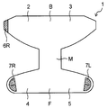
- Fig. 1 shows one embodiment of a diaper cover of the present invention.
- Fig. 2A shows an example of a wearing method of the diaper cover shown in Fig. 1, and shows the diaper cover in the state where the diaper cover is not worn and is spread in a plane.
- Fig. 2B shows an example of a wearing method of the diaper cover shown in Fig. 2A, and shows the diaper cover in the state where a right waist part and a left waist part are joined to each other.
- Fig. 2C shows an example of a wearing method of the diaper cover shown in Fig. 2B, and shows the diaper cover in the state where the diaper cover is worn.
- Fig. 3 shows an enlarged view of a flap part of the diaper cover shown in Fig. 1.
- Fig. 1 shows one embodiment of a diaper cover of the present invention.
- Fig. 2A shows an example of a wearing method of the diaper cover shown in Fig. 1, and shows the diaper cover in the state where the diaper cover is not worn and is spread in a plane.
- FIG. 4A shows one example of a cross sectional view along a line IV-IV in the flap part (a hook member) shown in Fig. 3.
- Fig. 4B shows another example of a cross sectional view along a line IV-IV in the flap part (a hook member) shown in Fig. 3.
- Fig. 5 shows one example of shape and arrangement of the hook member provided in the flap part.
- Fig. 6 shows an example of manufacturing the hook member shown in Fig. 5.
- Fig. 7 shows another example of shape and arrangement of the hook member provided in the flap part.
- Fig. 8 shows an example of manufacturing the hook member shown in Fig. 7.
- Fig. 9 shows still another example of shape and arrangement of the hook member provided in the flap part.
- Fig. 10 shows an example of manufacturing the hook member shown in Fig. 9.
- FIG. 11 shows still another example of shape and arrangement of the hook member provided in the flap part.
- Fig. 12 shows one embodiment of a disposable diaper of the present invention.
- Fig. 13 shows a cross-sectional view taken along line XIII-XIII in the disposable diaper shown in Fig. 12.
- FIG. 1 shows an example of the diaper cover of the present invention.
- the arrow x represents a width direction
- the arrow y represents a front-back direction.
- a diaper cover 1 has a front-back direction y and a width direction x.
- the front-back direction y means a direction extending in a front-back direction at a crotch of a wearer when the wearer wears the diaper cover.
- a lower side of the drawing corresponds to a front side of the diaper cover
- an upper side of the drawing corresponds to a back side of the diaper cover.
- the width direction x means a direction orthogonal to the front-back direction y on the same plane as the diaper cover.
- the width direction x corresponds to a direction extending in a right-left direction of a wearer when the wearer wears the diaper cover.
- the diaper cover 1 also has an inner side located on a wearer's side and an outer side located on opposite side of the wearer in wearing the diaper cover.
- the diaper cover 1 comprises a front part F, a back part B and an intermediate part M located therebetween in the front-back direction y.
- the front part F is formed at one end of the diaper cover 1 in the front-back direction y, and means a portion applied to an abdomen side of a wearer when the diaper cover is worn.
- the back part B is formed at the other end of the diaper cover 1 in the front-back direction y, and means a portion applied to a dorsal side of the wearer when the diaper cover is worn.
- the intermediate part M is positioned between the front part F and the back part B, and means a portion applied to a crotch of the wearer when the diaper cover is worn.
- the front part F, the back part B and the intermediate part M are parts excluding a right waist part 2, a left waist part 3, a right flap part 4 and a left flap part 5 described below.
- the front part F, the intermediate part M, the back part B, the right waist part 2, the left waist part 3, the right flap part 4 and the left flap part 5 are shown so as to be sectioned each other by dashed lines, conveniently.
- the front part F, the intermediate part M and the back part B occupy portions equivalent to 30%, 30%, and 40%, respectively, of the length of the diaper cover 1 in the front-back direction y.
- the diaper cover 1 shown in Fig. 1 is divided into the front part F, the intermediate part M and the back part B in such a ratio.
- the diaper cover 1 comprises the right waist part 2 and the left waist part 3 extending from the back part B in the width direction x.
- the right waist part 2 and the left waist part 3 are portions applied to a right side and a left side, respectively, of a waist of a wearer in wearing the diaper cover.
- a right side of the drawing corresponds to a left side of a wearer
- a left side of the drawing corresponds to a right side of the wearer in wearing the diaper cover.
- the diaper cover of Fig. 1 is shown such that the inner side of the diaper cover is seen.
- the diaper cover 1 is formed such that the intermediate part M is the narrowest in the width direction x.
- the right waist part 2 and the left waist part 3 correspond to portions located outward from outer edges of the narrowest part of the intermediate part M in the width direction x.
- the right waist part 2 and the left waist part 3 extend at least from the back part B in the width direction x, and may extend further from the intermediate part M in the width direction x.
- the diaper cover 1 covers the waist of a wearer with the right waist part 2, the left waist part 3 and the back part B when the diaper cover 1 is worn.
- the diaper cover 1 is worn such that the length of a portion where the right waist part 2 and the left waist part 3 overlap each other in the width direction x is about 10% or more and about 60% or less (more preferably about 20% or more and about 50% or less) of a waist circumference length of a wearer.
- the diaper cover 1 comprises the right flap part 4 and the left flap part 5 extending from the front part F in the width direction x.
- the right flap part 4 and the left flap part 5 correspond to portions located outward from the outer edges of the narrowest part of the intermediate part M in the width direction x.
- the right flap part 4 and the left flap part 5 extend at least from the front part F in the width direction x, and may extend further from the intermediate part M in the width direction x.
- the right flap part 4 and the left flap part 5 are portions which cover the abdomen of a wearer with the front part F when the diaper cover 1 is worn.
- the right flap part 4 and the left flap part 5 may be allowed to reach to the dorsal side of a wearer when the diaper cover 1 is worn.
- One or both of the right waist part 2 and the left waist part 3 is preferably provided with a waist attachment 6.
- the right waist part 2 and the left waist part 3 can be connected to each other by the waist attachment 6, whereby the right and left waist parts 2, 3 are easily fixed around the waist of a wearer.
- a reference sign "6R" may be used for representing the waist attachment provided at the right waist part
- a reference sign “6L” may be used for representing the waist attachment provided at the left waist part.
- the right and left waist parts 2, 3 can be fixed around the waist of a wearer by joining the right waist part 2 to the left waist part 3 or the back part B with the waist attachment 6R.
- the right flap part 4 and/or the left flap part 5 is provided with a hook member 7 having a plurality of hooks.
- each of the right flap part 4 and the left flap part 5 is provided with a hook member 7.
- a reference sign "7R" may be used for representing the hook fastener provided at the right flap part
- a reference sign "7L" may be used for representing the hook fastener provided at the left flap part.
- the hook members 7 of the right and left flap parts 4, 5 are preferably provided so as to be attachable to the outer surface (the surface located on the outer side) of the right waist part 2, the left waist part 3 or the back part B.
- the hook members 7 are preferably provided on the inner surfaces of the right and left flap parts 4, 5.
- the right and left flap parts 4, 5 are joined to the right waist part 2, left waist part 3 or the back part B, which has been applied around the waist of a wearer, by the hook members 7.
- the diaper cover 1 is applied tightly around the waist of the wearer, thereby enhancing fitting property of the diaper cover 1.
- the fitting property about inguinal region on the right side of a wearer is enhanced by edges of the right waist part 2, the right side of the intermediate part M, and the right flap part 4; and the fitting property about inguinal region on the left side of a wearer is enhanced by edges of the left waist part 3, the left side of the intermediate part M, and the left flap part 5.
- the hook member 7 is provided at the right flap part 4 and/or the left flap part 5 so as to be attachable to a position on the dorsal side or the lateral side of a wearer.
- the hook member 7 is preferably attachable to a position as far as 5% or more and 35% or less of the waist circumference length of a wearer away from the backbone (specifically, a centerline of the backbone) of the wearer, that is a region corresponding to 60% of the waist circumference length in all of right and left sides of a wearer.
- the centerline of the backbone means a centerline extending vertically in the state where the wearer stands.
- the right waist part 2 the left waist part 3 and the back part B are composed of a material to which the waist attachment 6 and the hook member 7 provided at the flap part are attachable.
- the right flap part and/or the left flap part may be simply referred to as a flap part.
- the right waist part 2 is brought into contact with the right side of the waist of the wearer, and the left waist part 3 is brought into contact with the left side of the waist of the wearer.
- the waist attachment 6R of the right waist part 2 is attached to the outer surface of the left waist part 3 while pulling the right waist part 2 (see Figs. 2A and 2B).
- the right and left waist parts 2, 3 are fixed around the waist of the wearer.
- the front part F, the right flap part 4 and the left flap part 5 are brought through the crotch of the wearer to the abdomen side of the wearer; the right flap part 4 and the left flap part 5 are pulled in the upward direction of the wearer while being pulled in the right-left direction of the wearer; and the right flap part 4 and the left flap part 5 are attached to the right waist part 2, the left waist part 3 or the back part B with the hook members 7 (see Figs. 2B and 2C).
- the diaper cover 1 can be worn.
- the hook members 7 provided at the right and left flap parts 4, 5 are joined to a position on the dorsal side of the wearer; however, the hook members 7 may be joined to a position on an abdomen side of the wearer.
- the hook member provided at the flap part is often joined to a position about the pelvis (that is, the ilium, particularly the iliac crest or the like) of a wearer.
- a great uneven or curved surface is found, and particularly, a great uneven or curved surface is formed with respect to the up-down direction of a wearer. Therefore, when the hook member is joined to such a position, the hook member is easily disjoined.
- forces acting in various directions such as inward in the left-right direction of a wearer and the lower direction of the wearer are tend to be applied to the hook member of the flap part.
- the hook member in order that joining (engaging) of the hook member provided at the flap part is less likely to be disjoined easily, the hook member has at least a first region and a second region, which are explained below in detail, and the first region and the second region are respectively oriented in particular directions.
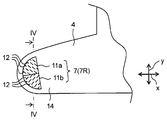
- FIG. 3 shows an enlarged view of the right flap part 4 of the diaper cover 1 shown in Fig. 1.
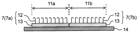
- Figs. 4A and 4B show a cross sectional view along a line IV-IV in the right flap part 4 shown in Fig. 3.
- Figs. 4A and 4B different embodiments of hook members 7R from each other are shown.
- the hook members 7 is provided on a main sheet 14 which forms the right flap part 4.
- the main sheet 14 forms, for example, the front part F, the intermediate part M, the back part B, the right waist part 2, the left waist part 3, the right flap part 4, and the left flap part 5.
- the hook member 7 includes, for example, a platform 13 and a plurality of hooks 12 projecting from the platform 13. The opposite surface of the surface with the hook 12 of the platform 13 is fixed to the main sheet 14.
- the hook 12 has a dogleg shape.
- a shape of the hook is not limited to the dogleg shape, and may be an anchor shape, a mushroom shape, or the like.
- the hook member 7 a plurality of pins serving as a part of the hooks 12 project from the platform 13, and an engagement part is provided at the top of the pin.
- the engagement part gives various shapes in accordance with the shape of the hook 12. For example, in a dogleg-shaped hook, the top of the pin bends in one direction.
- a crossbar is provided at the top of the pin as the engagement part.
- the crossbar does not necessarily have a rod shape, and any shape extending substantially point symmetrically with respect to the axis of the pin is allowed.
- a cap is provided at the top of the pin as the engagement part.
- the cap preferably has an anisotropic shape such as having a long axis direction and a short axis direction.
- the cap has an elliptical shape in a cross-section on a plane perpendicular to the axis of the pin.
- the anchor-shaped hook and the mushroom-shaped hook generally have a shape such that the engagement part is substantially point symmetrical with respect to axis of the pin.
- the hook member 7 has at least a first region 11a and a second region 11b, and the hooks 12 in the first region 11a are oriented in one direction and the hooks 12 in the second region 11b are oriented in another direction.
- the plurality of hooks 12 provided in the first region 11a and the plurality of hooks 12 provided in the second region 11b are respectively oriented uniformly in respective regions; however, the orientation direction of hooks 12 in the first region 11a and the orientation direction of hooks 12 in the second region 11b are different from each other.
- the orientation directions of hooks 12 are presented in lines.
- the hooks being oriented in one direction is explained as follows.
- the tops of the hooks are aligned in one direction.
- the tops of the hooks bend in one direction.
- the orientation directions of the crossbars provided at the tops of the pins are arranged in one direction.
- the orientation directions of the caps provided at the tops of the pins are arranged in one direction.
- the first region 11a and the second region 11b are arranged in the right flap part 4 or the left flap part 5 so that a following hypothetical line is presented. That is, in the diaper cover 1, there exist a hypothetical straight line extending in the front-back direction in the right flap part 4 or the left flap part 5 and crossing both the first region 11a and the second region 11b. In Fig. 3, the line IV-IV extends in the front-back direction y in the right flap part 4 and crosses both the first region 11a and the second region 11b, and thus, the line IV-IV corresponds to the hypothetical line.
- the hypothetical line does not need to exist so as to be visible, and is commonly invisible.
- the first region 11a and the second region 11b may be disposed so as to be aligned in the front-back direction y, for example.
- the first region 11a and the second region 11b may be also arranged in the front-back direction y while being shifted in the width direction x, as long as there exist a crossover between the projected first region and the projected second region onto a line extending in the width direction.
- the first region 11a and the second region 11b may be arranged obliquely to the width direction x and the front-back direction y.
- the hook member having the first region and the second region arranged in such a manner is provided in the flap part, joining (engaging) of the hook member is less likely to be disjoined easily when the diaper cover is worn. That is, since the hooks of the hook member are oriented in different directions between the first region and the second region, joining of both the first region and the second region are less likely to be disjoined at one time even when forces acting in various directions are applied to the hook member of the flap part.
- the first region and the second region are arranged such that the above-described hypothetical line is presented, the first region and the second region easily fit the uneven or curved surface of a wearer in the up-down direction of the wearer even when the hook member is joined to a position about the pelvis (that is, the ilium, particularly the iliac crest or the like) of the wearer.
- the first region and the second region can be suitably fixed to the right waist part, the left waist part, or the like.
- both the first region and the second region can resist against such forces when such forces are actually applied to the hook member.
- the one of the first region and the second region suppresses disjoining of the other of them, so that the joining of the hook member is not easily disjoined.
- the hook member may have a third region in addition to the first region and the second region.
- the orientation direction of the hooks in the third region may be the same as those in the first region or the second region, or may be different from those in the first region and the second region.
- the hooks in the third region are oriented in the direction which is different from the orientation directions of the hooks in the first region and the second region.
- the hypothetical straight line extending in the front-back direction in the right flap part or the left flap part and crossing both the first region and the second region may further crosses the third region or not.
- the hook member may further have a fourth region and other regions. However, description concerning the fourth region and other regions is omitted, since it is repetitive of the description of the third region.
- a position where the hook member is provided in the flap part is not limited; however, the hook member is preferably provided within 100 mm (more preferably within 80 mm, and even more preferably within 50 mm) from the end of the flap part in the width direction x.
- the hook member can be joined to the right waist part, the left waist part, or the like while holding the ends, with respect to the width direction x, of the flap parts, in wearing the diaper cover. Thereby, the diaper can be easily worn.
- a shape of a region where the hook member is disposed to the right or left flap part and shapes of the first region and the second region are not particularly limited. These shapes may be a circular sectoral shape (including semicircular shape), which is shown in Fig. 1, a linear shape having a width, a quadrangular shape (including a quadrangular shape whose corners are rounded), an elliptical shape, a triangular shape (including a triangular shape whose corners are rounded), or the like.
- the first region and the second region may be formed in one hook member or may be formed in different hook members.
- the first region 11a and the second region 11b are formed in one hook member 7.
- the first region 11a are formed in a hook member 7a and the second region 11b is formed in a hook member 7b which differs from the hook member 7a.
- the first region 11a and the second region 11b are preferably formed in different hook members 7a, 7b.
- the right flap part 4 and/or the left flap part 5 is preferably provided with the plurality of hook members 7 including a first hook member 7a having the first region 11a and a second hook member 7b having the second region 11b.
- the right flap part 4 and/or the left flap part 5 is provided with the first hook member 7a in which hooks 12 are oriented in one direction and the second hook member 7b in which hooks 12 are oriented in another direction.
- the hypothetical straight line crosses both the first hook member 7a and the second hook member 7b.
- the hook members are separated from each other. That is, the first hook member 7a and the second hook member 7b are preferably separated from each other.
- the hook members generally have a certain degree of rigidity; and, when the hook members are provided so as to be separated from each other, a portion of the flap part where the hook members are disposed easily fits the uneven or curved surface of a wearer.
- a distance (a shortest distance) between the separated hook members is preferably 0.5 mm or more, more preferably 1 mm or more, and preferably 10 mm or less, more preferably 7 mm or less.
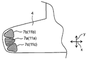
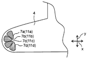
- Figs. 5, 7, 9 and 11 show hook members 7R which are provided in the right flap part 4.
- a first region 11a is formed in a first hook member 7a
- a second region 11b is formed in a second hook member 7b
- a third region 11c is formed in a third hook member 7c.
- a fourth region 11d is formed in a fourth hook member 7d.
- Fig. 5 shows one of preferred embodiment of the hook member, that is a first embodiment.
- the first hook member 7a narrows inward in the width direction x in the right flap part 4 (or the left flap part 5)
- the second hook member 7b narrows outward in the width direction x in the right flap part 4 (or the left flap part 5).
- the first hook member 7a is formed such that the end side, with respect to the right or left flap part 4, 5, is wider, the first hook member 7a can resist against a peeling force from the end side of the right or left flap part 4, 5 in wearing the diaper cover 1.
- the second hook member 7b is formed such that the inner side, with respect to the width direction x, of the right or left flap part 4, 5 is wider, the second hook member 7b can resist a peeling force from the inner side of the right or left flap part 4, 5 in wearing the diaper cover 1. Therefore, even when the front part F of the diaper cover 1 is distorted or twisted due to a wearer's heavy movement, the second hook member 7b is less likely to be disjoined to the right and left flap part 4, 5.
- the first hook member 7a and the second hook member 7b can be arranged close to each other in an end part of the right or left flap part 4, 5 in the width direction x, the total area of the hook members 7 can be easily enlarged. As a result, a total joining force of the hook members 7 is easily improved.
- the third hook member 7c is provided in addition to the first hook member 7a and the second hook member 7b.
- the third hook member 7c is preferably provided so as to narrow in the opposite direction to the adjacent hook member.
- the third hook member 7c since the third hook member 7c is adjacent to the first hook member 7a, the third hook member 7c preferably narrows outward in the width direction x. That is, in the case where three or more hook members are provided, the hook members are preferably respectively provided such that one of the adjacent hook members narrows inward in the width direction and the other of the adjacent hook members narrows outward in the width direction.
- the fourth hook member and other hook members are provided.
- examples of the shape of the first hook member and the second hook member include a triangular shape (including a triangular shape whose corners are rounded), a trapezoidal shape (including a trapezoidal shape whose corners are rounded), a circular sectoral shape (including a circular sectoral shape whose corners are rounded), and the like.
- the shape of the first and second hook members is a triangle whose corners are rounded.
- FIG. 6 shows a hook member sheet 21 in which a plurality of hooks 22 oriented in one direction, that is a right and left direction in the drawing, are provided.
- the first hook member and the second hook member are obtained by cutting out the hook member sheet 21 into, for example, triangle pieces 23 whose corners are rounded.
- the triangle pieces 23 whose corners are rounded are arranged such that the plurality of triangle pieces 23 form a substantial circle, and the triangle pieces 23 arranged in such a manner are cut out from the hook member sheet 21.
- first hook member and the second hook member are disposed on the right flap part (or the left flap part) such that the triangle pieces whose corners are rounded narrow inward or outward in the width direction x in the right flap part (or the left flap part), thereby obtaining the right flap part as shown in Fig. 5.
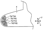
- Fig. 7 shows another preferred embodiment of the hook member, that is a second embodiment.
- each of the first hook member 7a and the second hook member 7b narrows inward from an edge of the right flap part 4 (or left flap part 5).
- the first hook member 7a and the second hook member 7b are respectively formed such that the outer sides, with respect to the width direction x, of the right or left flap part 4, 5 are wider, the first hook member 7a and the second hook member 7b can respectively resist a peeling force from the edge of the right or left flap part 4, 5 in wearing the diaper cover 1, and therefore, joining of each the first hook member 7a and the second hook member 7b is strengthened.
- first hook member 7a and the second hook member 7b can be arranged close to each other in the end part of the right or left flap part 4, 5 in the width direction x, the total area of the hook members 7 can be easily enlarged. As a result, a total joining force of the hook members 7 is easily improved.
- the third hook member 7c and the fourth hook member 7d are provided in addition to the first hook member 7a and the second hook member 7b; and it is also preferable that each of the third hook member 7c and the fourth hook member 7d narrows inward from the edge of the right flap part 4 (or left flap part 5).
- the same is applied to a case where the fifth hook member and other hook members are provided.
- the shape of the first and second hook members used in the second embodiment the shape of the hook member which can be employed in the first embodiment may be employed.
- the shape of the first and second hook members is a circular section whose corners are rounded.
- the hooks provided on the first hook member and the second hook member are preferably oriented toward the edge of the right flap part or the left flap part. That is, for example, in the dogleg-shaped hook, the tops of the hooks bend preferably toward the edge of the right or left flap part.
- the longitudinal directions of the crossbars provided at the tops of the pins are preferably oriented toward the edge of the right or left flap part.
- the long axes of the caps provided at the tops of the pins are preferably oriented toward the edge of the right or left flap part.
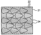
- FIG. 8 shows a hook member sheet 21 provided with a plurality of hooks 22 oriented in one direction, that is a right and left direction in the drawing.
- the first hook member and the second hook member are obtained by cutting out the hook member sheet 21 into, for example, circular sectors 24 whose corners are rounded.
- the circular sectors 24 whose corners are rounded are arranged so as to be oriented in one direction, and the circular sectors 24 whose corners are rounded arranged in such a manner are cut out from the hook member sheet 21.
- first hook member and the second hook member are disposed on the right flap part (or the left flap part) such that the circular sectors 24 whose corners are rounded narrow inward from the edge of the right flap part (or the left flap part), thereby obtaining the right flap part as shown in Fig. 7.
- the hooks provided on the first hook member and the second hook member come to be oriented toward the edge of the right flap part or the left flap part.
- Fig. 9 shows an embodiment in which the shape of the first hook member and the second hook member is different from that in Fig. 7.
- the shape of the first hook member and the second hook member is trapezoid.
- This effect is obtained particularly in the case where the shape of the engagement part is substantially point symmetrical with respect to the axis of the pin as in the anchor-shaped hook and the mushroom-shaped hook in the second embodiment.
- Similar effect is obtained in the case where the shape of the first hook member and the second hook member is not only trapezoid but also triangle. This is explained in the following with reference to Fig. 10.
- FIG. 10 shows a hook member sheet 21 provided with a plurality of hooks 22 oriented in one direction, that is a right and left direction in the drawing.
- a plurality of trapezoids 25 are arranged so as to be alternately changed in up-down direction (with respect to the upper and lower sides of the trapezoid), and the adjacent trapezoid pieces 25 are not separated from each other.
- the first hook member and the second hook member are obtained by cutting out the hook member sheet 21 into trapezoids 25.
- the hook member sheet 21 can generate less waste.
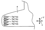
- Fig. 11 shows further another preferred embodiment of the hook member, that is a third embodiment.
- each of the first hook member 7a and the second hook member 7b narrows inward in the width direction x of the right flap part 4 (or left flap part 5).
- the first hook member 7a and the second hook member 7b are respectively formed such that the end sides, with respect to the right or left flap part 4, 5, are wider, the first hook member 7a and the second hook member 7b can respectively resist a peeling force from the end side of the right or left flap part 4, 5 in wearing the diaper cover 1, and therefore, joining of each the first hook member 7a and the second hook member 7b is strengthened.
- first hook member 7a and the second hook member 7b narrow inward in the width direction x, flexibility and stretchability of the main sheet are less likely to be inhibited by the hook member 7 at the inner side, with respect to the width direction x, of the right or left flap part 4, 5, thereby improving handleability of the diaper cover.
- the third hook member 7c and the fourth hook member 7d are provided in addition to the first hook member 7a and the second hook member 7b; and it is also preferable that each of the third hook member 7c and the fourth hook member 7d narrows inward in the width direction x of the right flap part 4 (or the left flap part 5).
- the same is applied to a case where the fifth hook member and other hook members are provided.
- the shape of the hook member which can be employed in the first embodiment may be employed.
- the shape of the first and second hook members is a circular section whose corners are rounded.
- the method shown in Fig. 6 can be employed.
- each of the right flap part 4 and the left flap part 5 is provided with the hook member 7 having the first region 11a and the second region 11b; however, it is only necessary that at least one of the right flap part 4 and the left flap part 5 is provided with the hook member 7 having the first region 11a and the second region 11b.
- either of the right flap part 4 or the left flap part 5 may be provided with a hook member having only the first region.
- either of the right flap part 4 or the left flap part 5 may be provided with an adhesive (e.g., an adhesive tape and an adhesive layer).
- each of the right flap part 4 and the left flap part 5 is preferably provided with the hook members 7 having the first region 11a and the second region 11b.
- the waist attachment 6 is explained in the following, referring to Fig. 1.
- the waist attachment 6R of the right waist part 2 is preferably provided so as to be attachable to the left waist part 3 or the back part B.
- the waist attachment 6L of the left waist part 3 is preferably provided so as to be attachable to the right waist part 2 or the back part B, although not shown in Fig. 1.
- the waist attachment 6R is preferably provided so as to be attachable to the left waist part 3
- the waist attachment 6L is preferably provided so as to be attachable to the right waist part 2.
- the waist attachment 6 may be provided on the inner surface of the right and left waist parts 2, 3.
- the waist attachment 6 comes to be attachable to the outer surface of the right waist part 2 or the left waist part 3, thereby improving handleability of the right and left waist parts 2, 3.
- the waist attachment 6R may be provided on the inner surface of the right waist part 2 and the waist attachment 6L may be provide on the outer surface of the left waist part 3.
- the waist attachment 6L is attached to the inner surface of the right waist part 2, and then the waist attachment 6R is attached to the outer surface of the left waist part 3 while overlapping the left waist part 3 with the right waist part 2, whereby the right and left waist parts can be easily fixed around the waist of a wearer stably.
- the surfaces of the right and left waist parts 2, 3 where the waist attachments 6R, 6L are provided may be reversed between the inner and outer surfaces.
- the waist attachment 6 may be provided so as to extend from the end of the right waist part 2 or the left waist part 3 in the width direction x.
- the waist attachment 6 is preferably provided at least on the inner surface of the right waist part 2 and/or the inner surface of the left waist part 3.
- the waist attachment 6 is provided on the inner surface of the right and left waist parts 2, 3, the waist attachment 6 is preferably provided within 100 mm (more preferably within 80 mm, and even more preferably within 50 mm) from the end of the right or left waist part 2, 3 in the width direction x.
- the waist attachments 6 are provided in such a manner, the waist attachments 6 can be joined to the right waist part 2, the left waist part 3 or the back part B while holding the ends, with respect to the width direction x, of the right waist part 2 and the left waist part 3, whereby the diaper cover 1 is easily worn.
- the waist attachment examples include a hook member and a loop member of a hook-and-loop fastener, an adhesive (e.g., an adhesive tape and an adhesive layer), a hook (e.g., a metallic hook and a plastic hook), and the like.
- a hook member of a hook-and-loop fastener is preferably used as the waist attachment.
- the hook member a member in which many hooks of, for example, an anchor shape, a dogleg shape, a mushroom shape, or the like are provided on the surface thereof can be employed.
- a hook member which can be used for the hook member provided in the flap part may be provided.
- a shape of the waist attachment that is a shape of a region where the waist attachment is disposed in the right or left waist part 2, 3, is not particularly limited.
- the shape of the waist attachment is long in the front-back direction y, and the waist attachment 6R having such shape is provided at the right waist part 2 in Fig. 1.
- the waist attachment having the shape long in the front-back direction y means that the length of the waist attachment in the front-back direction y is longer than that in the width direction x.
- the waist attachment does not necessarily provided so as to be parallel to the front-back direction y, and may be provided obliquely with respect to the front-back direction y.
- the waist attachment When the waist attachment has the shape long in the front-back direction y, the right and left waist parts can be widely joined, and thus are tend to be stably fixed around the waist of a wearer.
- the shape of the waist attachment include, for example, a linear shape, an elliptical shape, a quadrangular shape (including a quadrangular shape whose corners are rounded), a triangular shape (including a triangular shape whose corners are rounded), a circular sectoral shape (including a circular sectoral shape whose corners are rounded), and the like.
- the right flap part 4, the left flap part 5 and the intermediate part M are preferably stretchable.
- the edges of theses parts are applied to about an inguinal region of a wearer in wearing the diaper cover 1. Therefore, when the diaper 1 are stretchable at these parts, fitting property of the diaper cover a around legs of a wearer is easily improved by fixing the right and left flap parts 4, 5 around the waist of the wearer while the right and left flap parts 4, 5 being expanded in the right-left direction of the wearer and being pulled in the upward direction of the wearer.
- the front part F is also stretchable in addition to the right flap part 4, the left flap part 5 and the intermediate part M.
- the right waist part 2 and the left waist part 3 are preferably stretchable.
- the right waist part 2 and the left waist part 3 are preferably stretchable in the width direction x.
- fitting property of the diaper cover around the waist of a wearer is easily improved by fixing the right and left waist parts 2, 3 around the waist of the wearer while the right and left waist parts 2, 3 being expanded.
- the front part B is also stretchable in addition to the right waist part 2 and the left flap part 3.
- a material constituting the diaper cover that is, a material of the main sheet, is not particularly limited.
- the material constituting the diaper cover include a nonwoven fabric, a woven fabric, a knitted fabric, a plastic film, a laminate thereof, and the like.
- fabrics such as a nonwoven fabric, a woven fabric and a knitted fabric are used as the material constituting the diaper cover
- synthetic fibers such as polypropylene, polyethylene, polyesters, polyamides and polyurethanes; or natural fibers such as pulp and silk may be used as fibers constituting the fabric, for example.
- the material constituting the diaper cover synthetic resins such as polypropylene, polyethylene, polyesters, polyamides and polyurethanes may be used.
- the diaper cover may be either liquid-permeable or liquid-impermeable.
- a loop member of a hook-and-loop fastener is provided at the right and left waist parts and/or the back part, or the right and left waist parts and/or the back part are composed of a material which functions as the loop member, such as a nonwoven fabric, a woven fabric, a knitted fabric or the like.
- the hook member provided at the flap part can be fixed to the right and left waist parts and/or the back part in wearing of the diaper cover.
- the stretchable part is not particularly limited, as long as the stretchable part deforms with respect to a tensile load and generates force to return from its deformed shape to their original shape.
- the stretchable part preferably returns substantially to its original length even when being stretched at least 1.1-fold (more preferably 1.2-fold, even more preferably 1.5-fold), and preferably does not have yield point in the above stretching range.
- the stretchable part may be composed of a stretchable material.
- the stretchable material include natural rubbers; synthetic rubbers such as styrene-butadiene copolymer and polyisobutylene; synthetic resins such as polyurethanes, polyether-polyester, polybutylene terephthalate and polytrimethylene terephthalate; and the like.
- a nonwoven fabric, a woven fabric, a knitted fabric or the like which is composed of fibers containing the stretchable material may be used for the stretchable part.
- a film which the stretchable material is formed into may be used for the stretchable part.
- the stretchable part may be composed of a non-stretchable material.
- a woven fabric, a knitted fabric or the like which are composed of fibers formed from the non-stretchable material and is imparted stretching property by a weaving or knitting method, may be used for the stretchable part.
- the stretchable part may be composed of the stretchable material and the non-stretchable material.
- a stretchable material such as an elastic member and the like may be attached.
- the stretchable material is preferably attached to the non-stretchable part in a stretched state.
- a nonwoven fabric, a woven fabric, a knitted fabric or the like which is composed of fibers formed from the stretchable material and fibers formed from the non-stretchable material, or which are composed of composite fibers formed from the stretchable material and the non-stretchable material, may be used for the stretchable part.
- the entire diaper cover except the hook member provided at the flap part and the waist attachment may be stretchable.
- the diaper cover is preferably composed of an uniform material except the hook member provided at the flap part and the waist attachment, in view of easily manufacturing of the diaper cover.
- the diaper cover is preferably composed of a nonwoven fabric, a woven fabric, a knitted fabric or the like. More preferably, the entire diaper cover except the hook member and the waist attachment (when being provided), is composed of a nonwoven fabric, a woven fabric, a knitted fabric or the like.
- the present invention also provides a disposable diaper in which an absorbent core is provided at the intermediate part of the diaper cover of the present invention.
- the disposable diaper of the present invention comprises a front part, a back part and an intermediate part located between the front part and the back part in a front-back direction, a right waist part and a left waist part extending from the back part in a width direction, and a right flap part and a left flap part extending from the front part in the width direction, wherein: an absorbent core is provided at the intermediate part; the right flap part and/or the left flap part is provided with a hook member having a plurality of hooks; the hook member has a first region in which the hooks are oriented in one direction and a second region in which the hooks are oriented in another direction; and the first region and the second region are arranged such that a hypothetical straight line extending in the front-back direction in the right flap part or the left flap part crosses both the first region and the second region.
- the disposable diaper may comprise: an exterior sheet having a front part, a back part and an intermediate part located therebetween in a front-back direction, a right waist part and a left waist part extending from the back part in a width direction, and a right flap part and a left flap part extending from the front part in the width direction; and an absorbent main body including a liquid-permeable top sheet, a liquid-impermeable back sheet and an absorbent core interposed therebetween; wherein the absorbent main body is provided at the intermediate part of the exterior sheet.
- the exterior sheet may be composed of one sheet or may be formed by laminating two or more sheets.
- the exterior sheet include, for example, a laminate of an inner sheet and an outer sheet.
- the inner sheet is preferably hydrophilic or water-repellent
- the outer sheet is preferably water-repellent.
- the exterior sheet may have a stretchable part and a non-stretchable part.
- the disposable diaper may comprise a laminate including a liquid-permeable top sheet, a liquid-impermeable back sheet and an absorbent core interposed therebetween, wherein the laminate has a front part, a back part and an intermediate part located therebetween in a front-back direction, a right waist part and a left waist part extending from the back part in a width direction, and a right flap part and a left flap part extending from the front part in the width direction, and the absorbent core is provided at the intermediate part.
- the laminate may have a stretchable part and a non-stretchable part.
- a laminate in which an absorbent core is interposed between a liquid-permeable top sheet and a liquid-impermeable back sheet may form a non-stretchable part, and the remaining parts composed of a material which is different from materials of the top sheet and the back sheet may form a stretchable part.
- the absorbent core is not particularly restricted as long as it absorbs excrement such as urine and the like.
- a clump of an absorbent material which is formed into a predefined shape, may be used, or an absorbent material wrapped with a covering sheet such as paper (for example, tissue paper), a liquid-permeable nonwoven fabric and the like may be used, for example.
- the absorbent material contained in the absorbent core include, for example, a hydrophilic fiber such as a crushed pulp fiber and a cellulose fiber; and an absorbent polymer such as polyacrylic absorbent polymer, cellulosic absorbent polymer, and stark-acrylonitrile absorbent polymer.
- the absorbent material preferably contains at least an absorbent polymer.
- the absorbent material may be obtained by mixing an absorbent polymer with a hydrophilic fiber assembly, or dispersing an absorbent polymer on a hydrophilic fiber assembly.
- a shape of the absorbent core is not limited. Examples of the shape of the absorbent core include a rectangular shape, an hourglass shape, a center nipped-in gourd shape, a battledore shape and the like.
- the top sheet and the back sheet may be composed of a nonwoven fabric, a woven fabric, a knitted fabric, a plastic film, a laminate of a plastic film and a nonwoven fabric, or the like.
- the laminate include a laminate in which a sheet of a nonwoven fabric and a sheet of a plastic film are stacked, and a laminate in which a plastic film is interposed between nonwoven fabrics.
- the top sheet examples include, for example, a nonwoven fabric formed from hydrophilic fibers such as cellulose and rayon; and a nonwoven fabric which is formed from hydrophobic fibers such as polypropylene, polyethylene, polyester, polyamide and nylon, and in which the hydrophobic fibers are hydrophilized with a surfactant on the surface thereof.
- a woven fabric, a knitted fabric, a plastic film having pores may be also used.
- the back sheet examples include, for example, a nonwoven fabric formed from hydrophobic fibers such as polypropylene, polyethylene, polyester, polyamide and nylon; and a plastic film.
- a nonwoven fabric formed from hydrophobic fibers such as polypropylene, polyethylene, polyester, polyamide and nylon
- a plastic film As the back sheet, a laminate of a nonwoven fabric and a plastic film may be also used.
- a material which can be used for the back sheet is preferably used in the case that the exterior sheet is composed of one sheet.
- the exterior sheet comprises the inner sheet and the outer sheet
- a material which can be used for the top sheet or the back sheet may be used as the inner sheet
- a material which can be used for the back sheet may be used as the outer sheet.
- a nonwoven fabric manufactured by a spunbonding method, an air-through method, a point bonding method, a melt blowing method, an airlaid method, a combination of these methods, or the like is preferably used.
- a nonwoven fabric manufactured by an SMS method which is a combination of the spunbonding method and the melt blowing method may be used.
- the disposable diaper preferably comprises rising flaps disposed at opposite sides of the absorbent core.
- the rising flaps may be provided on an upper surface of the absorbent core at both sides in the width direction, or may be provided outside the absorbent core in the width direction.
- the rising flaps enable to prevent lateral leakage of urine and the like.
- the rising flaps may be formed by rising inner edges of side sheets joined to opposite sides of the top sheet in the width direction.
- the rising flap and the side sheet are preferably water-repellent.
- Fig. 12 shows an example of the disposable diaper of the present invention
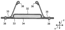
- Fig. 13 shows a cross-sectional view taken along line XIII-XIII in Fig. 12.
- the disposable diaper of the present invention is not restricted to the following embodiment. In the following, description of the part overlapping the above description of the diaper cover is omitted. Further, the terms “diaper cover” and “diaper cover 1" in the above description of the diaper cover are respectively replaced with the terms "disposable diaper” and "disposable diaper 31".
- a disposable diaper 31 comprises a laminate in which an absorbent core 34 is interposed between a liquid-permeable top sheet 32 and a liquid-impermeable back sheet 33.
- the top sheet 32 has a rectangular shape such that length in the width direction x is shorter than length in the width direction x of the intermediate part, and length in the front-back direction y is the substantially same as length in the front-back direction y of the disposable diaper 31.
- the back sheet 33 forms the front part, the back part and the intermediate part located therebetween in the front-back direction y, the right waist part 2 and the left waist part 3 extending from the back part in the width direction x, and the right flap part 4 and the left flap part 5 extending from the front part in the width direction x.
- Side sheets 35 are joined to both ends of the top sheet 32 in the width direction x, and the side sheets 35 forms the right waist part 2, the left waist part 3, the right flap part 4 and the left flap part 5.
- the top sheet 32 is placed so as to face a wearer's skin, and allows excrement such as urine and the like to permeate through.
- the excrement that permeated the top sheet 32 is accommodated in the absorbent core 34.
- the back sheet 33 prevents the excrement from permeating outside, thereby protecting clothes and the like becoming soiled.
- a rising elastic member 36 is disposed at an inner end, with respect to the width direction x, of the side sheet 35.
- the inner part of the side sheet 35 rises above the top sheet 32 due to a shrinkage force of the rising elastic member 36.
- the inner part of the side sheet 35 rises toward a wearer's skin to form a rising flap, thereby preventing excrement such as urine and the like from leaking outward in the width direction x.
- Waist elastic members 37 extending in the width direction x are disposed in the right and left waist parts 2, 3. Parts of the right and left waist parts 2, 3 where the waist elastic members 37 are disposed function as the stretchable parts.
- Leg elastic members 38 extending in the front-back direction y are disposed the intermediate part.
- the elastic member 38 is disposed in the intermediate part along the edge of the disposable diaper 31.
- Flap elastic members 39 approximately extending in the width direction x are disposed in the right and left flap parts 4, 5.
- the leg elastic member 38 and the flap elastic member 39 improve fitting property around the legs of a wearer.
- the waist elastic member 37, the leg elastic member 38 and the flap elastic member 39 are respectively disposed between the side sheet 35 and the back sheet 33, and fixed to side sheet 35 and the back sheet 33 in stretched states.
- Elastic materials such as a polyurethane thread, a polyurethane film, a natural rubber and the like, which are generally used for disposable diapers, can be used for the respective elastic members.
- the respective elastic members are preferably fixed in stretched states with a hot-melt adhesive.
- a polyurethane thread having a fineness of 100 dtex to 2,500 dtex is stretched at a ratio of 1.1 to 5.0 times to be fixed.
- a preferable fixing means is a rubber hot-melt adhesive.
- a diaper cover 2 a right waist part 3: a left waist part 4: a right flap part 5: a left flap part 6: a waist attachment 7: a hook member 11a: a first region 11b: a second region 12: a hook 31: a disposable diaper
Abstract
Description
2: a right waist part
3: a left waist part
4: a right flap part
5: a left flap part
6: a waist attachment
7: a hook member
11a: a first region
11b: a second region
12: a hook
31: a disposable diaper
Claims (9)
- A diaper cover comprising a front part, a back part and an intermediate part located between the front part and the back part in a front-back direction, a right waist part and a left waist part extending from the back part in a width direction, and a right flap part and a left flap part extending from the front part in the width direction, wherein
the right flap part and/or the left flap part is provided with a hook member having a plurality of hooks,
the hook member has a first region in which the hooks are oriented in one direction and a second region in which the hooks are oriented in another direction, and
the first region and the second region are arranged such that a hypothetical straight line extending in the front-back direction in the right flap part or the left flap part crosses both the first region and the second region. - The diaper cover according to claim 1, wherein
the right flap part and/or the left flap part is provided with the plurality of hook members including a first hook member having the first region and a second hook member having the second region, and
the first hook member and the second hook member are arranged such that the hypothetical straight line crosses both the first hook member and the second hook member. - The diaper cover according to claim 2, wherein the first hook member narrows inward in the width direction in the right or left flap part, and the second hook member narrows outward in the width direction in the right or left flap part.
- The diaper cover according to claim 2, wherein each of the first hook member and the second hook member narrows inward from an edge of the right or left flap part.
- The diaper cover according to claim 2, wherein each of the first hook member and the second hook member narrows inward in the width direction in the right or left flap part.
- The diaper cover according to any one of claims 2 to 5, wherein the first hook member and the second hook member are separated from each other.
- The diaper cover according to any one of claims 1 to 6, wherein the right flap part, the left flap part and the intermediate part are stretchable.
- The diaper cover according to any one of claims 1 to 7, wherein one or both of the right waist part and the left waist part is provided with a waist attachment.
- A disposable diaper comprising
the diaper cover according to any one of claims 1 to 8, and
an absorbent core provided at the intermediate part of the diaper cover.
Priority Applications (4)
| Application Number | Priority Date | Filing Date | Title |
|---|---|---|---|
| AU2011241721A AU2011241721B2 (en) | 2010-04-14 | 2011-04-12 | Diaper cover and disposable diaper |
| EP11720893A EP2558051A1 (en) | 2010-04-14 | 2011-04-12 | Diaper cover and disposable diaper |
| CN2011800083333A CN102740820A (en) | 2010-04-14 | 2011-04-12 | Diaper cover and disposable diaper |
| US13/577,728 US8834442B2 (en) | 2010-04-14 | 2011-04-12 | Diaper cover and disposable diaper |
Applications Claiming Priority (4)
| Application Number | Priority Date | Filing Date | Title |
|---|---|---|---|
| JP2010-093573 | 2010-04-14 | ||
| JP2010093573 | 2010-04-14 | ||
| JP2010132456A JP2011235076A (en) | 2010-04-14 | 2010-06-09 | Diaper cover and disposable diaper |
| JP2010-132456 | 2010-06-09 |
Publications (1)
| Publication Number | Publication Date |
|---|---|
| WO2011129097A1 true WO2011129097A1 (en) | 2011-10-20 |
Family
ID=44205774
Family Applications (1)
| Application Number | Title | Priority Date | Filing Date |
|---|---|---|---|
| PCT/JP2011/002146 WO2011129097A1 (en) | 2010-04-14 | 2011-04-12 | Diaper cover and disposable diaper |
Country Status (7)
| Country | Link |
|---|---|
| US (1) | US8834442B2 (en) |
| EP (1) | EP2558051A1 (en) |
| JP (1) | JP2011235076A (en) |
| CN (1) | CN102740820A (en) |
| AU (1) | AU2011241721B2 (en) |
| TW (1) | TW201143734A (en) |
| WO (1) | WO2011129097A1 (en) |
Cited By (3)
| Publication number | Priority date | Publication date | Assignee | Title |
|---|---|---|---|---|
| US20210145662A1 (en) * | 2019-11-15 | 2021-05-20 | The Procter & Gamble Company | Absorbent article having fastening system |
| US20210251825A1 (en) * | 2020-02-13 | 2021-08-19 | The Procter & Gamble Company | Absorbent article with fastening system |
| US11801168B2 (en) | 2019-11-15 | 2023-10-31 | The Procter And Gamble Company | Tape-type absorbent article with belt structure |
Families Citing this family (4)
| Publication number | Priority date | Publication date | Assignee | Title |
|---|---|---|---|---|
| USD677447S1 (en) * | 2012-02-09 | 2013-03-12 | Susanne L. Shoemaker | Panty garment |
| JP7134588B2 (en) | 2016-03-30 | 2022-09-12 | 大王製紙株式会社 | disposable diaper |
| JP2019118544A (en) * | 2017-12-28 | 2019-07-22 | ユニ・チャーム株式会社 | Disposable wear article |
| WO2020041271A1 (en) * | 2018-08-21 | 2020-02-27 | The Procter & Gamble Company | Fastening systems comprising nonwoven substrates with hooks formed integrally thereon |
Citations (5)
| Publication number | Priority date | Publication date | Assignee | Title |
|---|---|---|---|---|
| US5300058A (en) * | 1992-12-10 | 1994-04-05 | The Procter & Gamble Company | Disposable absorbent article having an improved mechanical fastening system |
| WO1997036566A1 (en) * | 1996-04-02 | 1997-10-09 | The Procter & Gamble Company | Elastomeric side panel for use with convertible absorbent articles |
| US5884374A (en) * | 1997-11-20 | 1999-03-23 | Velcro Industries B.V. | Fastener members and apparatus for their fabrication |
| WO2002014701A2 (en) * | 2000-08-11 | 2002-02-21 | Kimberly-Clark Worldwide, Inc. | Male fasteners with angled projections |
| JP2006042863A (en) | 2004-07-30 | 2006-02-16 | Kao Corp | Disposable diaper |
Family Cites Families (10)
| Publication number | Priority date | Publication date | Assignee | Title |
|---|---|---|---|---|
| CA2053106A1 (en) | 1991-08-08 | 1993-02-09 | Mary A. Bruemmer | Disposable diaper enabling standing application with childproof fastening |
| US20020188268A1 (en) * | 1999-06-30 | 2002-12-12 | Mark James Kline | Elastomeric side panel for use with convertible absorbent articles |
| US5669901A (en) * | 1996-04-18 | 1997-09-23 | Kimberly-Clark Worldwide, Inc. | Absorbent article having an improved mechanical fastening system |
| AR021477A1 (en) * | 1998-09-17 | 2002-07-24 | Kimberly Clark Co | AN ARTICLE THAT HAS A MECHANICAL CLAMPING SYSTEM WITH SECTIONS WITH COUPLING MEMBERS |
| CA2457450A1 (en) * | 2001-08-20 | 2003-02-27 | Kimberly-Clark Worldwide, Inc. | Mechanical fastening system having orthogonally oriented engagement members |
| US20030120251A1 (en) * | 2001-12-20 | 2003-06-26 | Couture Denise R. | Mechanical fastening system having orthogonally oriented engagement members |
| JP2003190213A (en) * | 2001-12-28 | 2003-07-08 | Koyo:Kk | Diaper cover |
| EP1484041A1 (en) | 2003-06-06 | 2004-12-08 | 3M Innovative Properties Company | Fastening film system and assembly comprising a fastening film system and a substrate |
| JP4130187B2 (en) * | 2004-11-17 | 2008-08-06 | 花王株式会社 | Disposable diapers |
| JP5497995B2 (en) * | 2008-05-15 | 2014-05-21 | ユニ・チャーム株式会社 | Wearing article |
-
2010
- 2010-06-09 JP JP2010132456A patent/JP2011235076A/en active Pending
-
2011
- 2011-04-12 WO PCT/JP2011/002146 patent/WO2011129097A1/en active Application Filing
- 2011-04-12 US US13/577,728 patent/US8834442B2/en not_active Expired - Fee Related
- 2011-04-12 TW TW100112584A patent/TW201143734A/en unknown
- 2011-04-12 CN CN2011800083333A patent/CN102740820A/en active Pending
- 2011-04-12 AU AU2011241721A patent/AU2011241721B2/en not_active Ceased
- 2011-04-12 EP EP11720893A patent/EP2558051A1/en not_active Withdrawn
Patent Citations (5)
| Publication number | Priority date | Publication date | Assignee | Title |
|---|---|---|---|---|
| US5300058A (en) * | 1992-12-10 | 1994-04-05 | The Procter & Gamble Company | Disposable absorbent article having an improved mechanical fastening system |
| WO1997036566A1 (en) * | 1996-04-02 | 1997-10-09 | The Procter & Gamble Company | Elastomeric side panel for use with convertible absorbent articles |
| US5884374A (en) * | 1997-11-20 | 1999-03-23 | Velcro Industries B.V. | Fastener members and apparatus for their fabrication |
| WO2002014701A2 (en) * | 2000-08-11 | 2002-02-21 | Kimberly-Clark Worldwide, Inc. | Male fasteners with angled projections |
| JP2006042863A (en) | 2004-07-30 | 2006-02-16 | Kao Corp | Disposable diaper |
Non-Patent Citations (1)
| Title |
|---|
| See also references of EP2558051A1 * |
Cited By (5)
| Publication number | Priority date | Publication date | Assignee | Title |
|---|---|---|---|---|
| US20210145662A1 (en) * | 2019-11-15 | 2021-05-20 | The Procter & Gamble Company | Absorbent article having fastening system |
| US20210145663A1 (en) * | 2019-11-15 | 2021-05-20 | The Procter & Gamble Company | Absorbent article having fastening system |
| US11793685B2 (en) | 2019-11-15 | 2023-10-24 | The Procter And Gamble Company | Absorbent article having fastening system |
| US11801168B2 (en) | 2019-11-15 | 2023-10-31 | The Procter And Gamble Company | Tape-type absorbent article with belt structure |
| US20210251825A1 (en) * | 2020-02-13 | 2021-08-19 | The Procter & Gamble Company | Absorbent article with fastening system |
Also Published As
| Publication number | Publication date |
|---|---|
| AU2011241721B2 (en) | 2014-01-30 |
| AU2011241721A1 (en) | 2012-09-06 |
| US8834442B2 (en) | 2014-09-16 |
| US20120316535A1 (en) | 2012-12-13 |
| CN102740820A (en) | 2012-10-17 |
| TW201143734A (en) | 2011-12-16 |
| JP2011235076A (en) | 2011-11-24 |
| EP2558051A1 (en) | 2013-02-20 |
Similar Documents
| Publication | Publication Date | Title |
|---|---|---|
| US8834442B2 (en) | Diaper cover and disposable diaper | |
| JP5301880B2 (en) | Disposable absorbent article | |
| JP5210447B1 (en) | Disposable diapers | |
| EP2408412A1 (en) | Disposable diaper having a fastening tape with stepwise adjustable length | |
| JP2011200336A (en) | Fixing tape, disposable diaper using the fixing tape | |
| US8216206B2 (en) | Disposable absorbent article | |
| JP2011147711A (en) | Disposable diaper | |
| JP6310295B2 (en) | Absorbent articles | |
| JP5572526B2 (en) | Diapers | |
| JP2011010822A (en) | Disposable diaper | |
| JP2011183059A (en) | Fixing tape and disposable diaper furnished with the fixing tape | |
| JP6261641B2 (en) | Disposable diapers | |
| JP5520620B2 (en) | Disposable diapers | |
| JP2014117322A (en) | Disposable diaper and diaper cover | |
| JP6754543B2 (en) | Disposable diapers | |
| JP5599502B2 (en) | Disposable diapers | |
| JP7104823B1 (en) | Disposable diapers with fastening tape and fastening tape | |
| JP6208598B2 (en) | Absorbent articles | |
| US8066684B2 (en) | Disposable pants | |
| JP2011177244A (en) | Disposable diaper | |
| JP2011156275A (en) | Diaper cover and disposable diaper | |
| JP5559558B2 (en) | Diaper covers and disposable diapers | |
| JP5783711B2 (en) | Disposable diapers | |
| JP2019024932A (en) | Disposable diaper | |
| JP2014079289A (en) | Open type disposable diaper |
Legal Events
| Date | Code | Title | Description |
|---|---|---|---|
| WWE | Wipo information: entry into national phase |
Ref document number: 201180008333.3 Country of ref document: CN |
|
| 121 | Ep: the epo has been informed by wipo that ep was designated in this application |
Ref document number: 11720893 Country of ref document: EP Kind code of ref document: A1 |
|
| WWE | Wipo information: entry into national phase |
Ref document number: 13577728 Country of ref document: US |
|
| WWE | Wipo information: entry into national phase |
Ref document number: 2011241721 Country of ref document: AU Ref document number: 2011720893 Country of ref document: EP |
|
| ENP | Entry into the national phase |
Ref document number: 2011241721 Country of ref document: AU Date of ref document: 20110412 Kind code of ref document: A |
|
| NENP | Non-entry into the national phase |
Ref country code: DE |