WO2011085146A2 - Compact light-mixing led light engine and white led lamp with narrow beam and high cri using same - Google Patents
Compact light-mixing led light engine and white led lamp with narrow beam and high cri using same Download PDFInfo
- Publication number
- WO2011085146A2 WO2011085146A2 PCT/US2011/020442 US2011020442W WO2011085146A2 WO 2011085146 A2 WO2011085146 A2 WO 2011085146A2 US 2011020442 W US2011020442 W US 2011020442W WO 2011085146 A2 WO2011085146 A2 WO 2011085146A2
- Authority
- WO
- WIPO (PCT)
- Prior art keywords
- light
- lens
- set forth
- diffuser
- light source
- Prior art date
Links
Classifications
-
- F—MECHANICAL ENGINEERING; LIGHTING; HEATING; WEAPONS; BLASTING
- F21—LIGHTING
- F21K—NON-ELECTRIC LIGHT SOURCES USING LUMINESCENCE; LIGHT SOURCES USING ELECTROCHEMILUMINESCENCE; LIGHT SOURCES USING CHARGES OF COMBUSTIBLE MATERIAL; LIGHT SOURCES USING SEMICONDUCTOR DEVICES AS LIGHT-GENERATING ELEMENTS; LIGHT SOURCES NOT OTHERWISE PROVIDED FOR
- F21K9/00—Light sources using semiconductor devices as light-generating elements, e.g. using light-emitting diodes [LED] or lasers
- F21K9/20—Light sources comprising attachment means
- F21K9/23—Retrofit light sources for lighting devices with a single fitting for each light source, e.g. for substitution of incandescent lamps with bayonet or threaded fittings
- F21K9/233—Retrofit light sources for lighting devices with a single fitting for each light source, e.g. for substitution of incandescent lamps with bayonet or threaded fittings specially adapted for generating a spot light distribution, e.g. for substitution of reflector lamps
-
- F—MECHANICAL ENGINEERING; LIGHTING; HEATING; WEAPONS; BLASTING
- F21—LIGHTING
- F21K—NON-ELECTRIC LIGHT SOURCES USING LUMINESCENCE; LIGHT SOURCES USING ELECTROCHEMILUMINESCENCE; LIGHT SOURCES USING CHARGES OF COMBUSTIBLE MATERIAL; LIGHT SOURCES USING SEMICONDUCTOR DEVICES AS LIGHT-GENERATING ELEMENTS; LIGHT SOURCES NOT OTHERWISE PROVIDED FOR
- F21K9/00—Light sources using semiconductor devices as light-generating elements, e.g. using light-emitting diodes [LED] or lasers
- F21K9/60—Optical arrangements integrated in the light source, e.g. for improving the colour rendering index or the light extraction
-
- F—MECHANICAL ENGINEERING; LIGHTING; HEATING; WEAPONS; BLASTING
- F21—LIGHTING
- F21V—FUNCTIONAL FEATURES OR DETAILS OF LIGHTING DEVICES OR SYSTEMS THEREOF; STRUCTURAL COMBINATIONS OF LIGHTING DEVICES WITH OTHER ARTICLES, NOT OTHERWISE PROVIDED FOR
- F21V13/00—Producing particular characteristics or distribution of the light emitted by means of a combination of elements specified in two or more of main groups F21V1/00 - F21V11/00
- F21V13/12—Combinations of only three kinds of elements
-
- F—MECHANICAL ENGINEERING; LIGHTING; HEATING; WEAPONS; BLASTING
- F21—LIGHTING
- F21V—FUNCTIONAL FEATURES OR DETAILS OF LIGHTING DEVICES OR SYSTEMS THEREOF; STRUCTURAL COMBINATIONS OF LIGHTING DEVICES WITH OTHER ARTICLES, NOT OTHERWISE PROVIDED FOR
- F21V3/00—Globes; Bowls; Cover glasses
-
- F—MECHANICAL ENGINEERING; LIGHTING; HEATING; WEAPONS; BLASTING
- F21—LIGHTING
- F21V—FUNCTIONAL FEATURES OR DETAILS OF LIGHTING DEVICES OR SYSTEMS THEREOF; STRUCTURAL COMBINATIONS OF LIGHTING DEVICES WITH OTHER ARTICLES, NOT OTHERWISE PROVIDED FOR
- F21V5/00—Refractors for light sources
- F21V5/04—Refractors for light sources of lens shape
-
- F—MECHANICAL ENGINEERING; LIGHTING; HEATING; WEAPONS; BLASTING
- F21—LIGHTING
- F21V—FUNCTIONAL FEATURES OR DETAILS OF LIGHTING DEVICES OR SYSTEMS THEREOF; STRUCTURAL COMBINATIONS OF LIGHTING DEVICES WITH OTHER ARTICLES, NOT OTHERWISE PROVIDED FOR
- F21V7/00—Reflectors for light sources
-
- F—MECHANICAL ENGINEERING; LIGHTING; HEATING; WEAPONS; BLASTING
- F21—LIGHTING
- F21Y—INDEXING SCHEME ASSOCIATED WITH SUBCLASSES F21K, F21L, F21S and F21V, RELATING TO THE FORM OR THE KIND OF THE LIGHT SOURCES OR OF THE COLOUR OF THE LIGHT EMITTED
- F21Y2105/00—Planar light sources
- F21Y2105/10—Planar light sources comprising a two-dimensional array of point-like light-generating elements
- F21Y2105/12—Planar light sources comprising a two-dimensional array of point-like light-generating elements characterised by the geometrical disposition of the light-generating elements, e.g. arranging light-generating elements in differing patterns or densities
-
- F—MECHANICAL ENGINEERING; LIGHTING; HEATING; WEAPONS; BLASTING
- F21—LIGHTING
- F21Y—INDEXING SCHEME ASSOCIATED WITH SUBCLASSES F21K, F21L, F21S and F21V, RELATING TO THE FORM OR THE KIND OF THE LIGHT SOURCES OR OF THE COLOUR OF THE LIGHT EMITTED
- F21Y2115/00—Light-generating elements of semiconductor light sources
- F21Y2115/10—Light-emitting diodes [LED]
Definitions
- the following relates to the illumination arts, lighting arts, solid state lighting arts, and related arts.
- Incandescent and halogen lamps are conventionally used as both omni-directional and directional light sources.
- a directional lamp is defined by the US Department of Energy in its Energy Star Eligibility Criteria for Integral LED Lamps, draft 3, as a lamp having at least 80% of its light output within a cone angle of 120 degrees (full-width at half-maximum of intensity, FWHM). They may have either broad beam patterns (flood lamps) or narrow beam patterns (e.g., spot lamps), for example having a beam intensity distribution characterized by a FWHM ⁇ 20°, with some lamp standards specified for angles as small as 6-10° FWHM.
- Incandescent and halogen lamps combine these desirable beam characteristics with high color rendering index (CRI) to provide good light sources for the display of retail merchandise, residential and hospitality lighting, art work, etc.
- CRI color rendering index
- these lamps are designed to fit into a standard MR-x, PAR-x, or R-x lamp fixture, where "x" denotes the outer diameter of the fixture, in eighths of an inch (e.g. PAR38 has 4.75" lamp diameter ⁇ 120 mm).
- PAR38 has 4.75" lamp diameter ⁇ 120 mm.
- These lamps have fast response time, output high light intensity, and have good CRI characteristics, especially for saturated red (e.g., the R9 CRI parameter), but suffer from poor efficacy and relatively short lamp life.
- high intensity discharge (HID) lamps are used, at the cost of reduced response time due to the need to heat the liquid and solid dose during the warm-up phase after turning on the lamp, and typically also reduced color quality, higher cost, and moderate lamp life ⁇ 10k - 20k hours.
- solid-state lighting technologies such as light emitting diode (LED) device technologies.
- LED light emitting diode
- the desirable characteristics of incandescent and halogen spot lamps include: color quality; color uniformity; beam control; and low acquisition cost.
- the undesirable characteristics include: poor efficacy; short life; excessive heat generation; and high life-cycle operating cost.
- LED device technologies have been less than satisfactory in replacing incandescent and halogen lamps. It has been difficult using LED device technologies to simultaneously achieve a combination of both good color and good beam control for spot lamps.
- LED-based narrow-beam spot lighting has been achieved using white LEDs as point light sources coupled with suitable lenses or other collimating optics. This type of LED device can be made with narrow FWHM in a lamp envelope comporting with MR/PAR/R fixture specifications.
- these lamps have CRI characteristics corresponding to that of the white LEDs, which is unsatisfactory in some applications. For example, such LED devices typically produce R9 values of less than 30, and CRI ⁇ 80-85 (where a value of 100 is ideal) which is unacceptable for spot light applications such as product displays, theater and museum lighting, restaurant and residential lighting, and so forth.
- LED based lighting applications other than spot lighting have successfully achieved high CRI by combining white LED devices with red LED devices that compensate for the red deficient spectrum of typical white LED devices. See, e.g., Van De Ven et al, U.S. Pat. No. 7,213,940.
- a large area diffuser is employed that encompasses the array of red and white LED devices. Lamps based on this technology have provided good CRI characteristics, but have not produced spot lighting due to large beam FWHM values, typically of order 100° or higher.
- a combination of good color quality, good beam control and uniform illuminance and color in the beam has also been achieved by using a deep (or long) color-mixing cavity that provides multiple reflections of the light, or a long distance between the LED array and the diffuser plate, albeit at the cost of increased light losses due to cavity absorption, and increased lamp size.
- Harbers et al, U.S. Publ. Appl. No. 2009/0103296 Al discloses combining a color-mixing cavity consisting of an array of LED devices mounted on an extended planar substrate that is mounted at the small aperture end of a compound parabolic concentrator.
- Such designs are calculated to theoretically provide arbitrarily small beam FWHM by using a color-mixing cavity of sufficiently small aperture.
- a color-mixing cavity of 32 mm diameter coupled with a compound parabolic concentrator could provide a beam FWHM of 30°.
- Harbers et al. the compound parabolic concentrator design tends to be tall. This could be problematic for an MR or PAR lamp which has a specified maximum length imposed by the MR/PAR/R regulatory standard to ensure compatibility with existing MR/PAR/R lamp sockets. Harbers et al. also proposed using a truncated compound parabolic concentrator having a truncated length in place of the simulated compound parabolic reflector. However, Harbers et al. indicate that truncation is expected to increase the beam angle. Another approach proposed in Harbers et al.
- a directional lamp comprises a light source, a beam forming optical system configured to form light from the light source into a light beam, and a light mixing diffuser arranged to diffuse the light beam.
- the light source, beam forming optical system, and light mixing diffuser are secured together as a unitary lamp.
- the beam forming optical system includes: a collecting reflector having an entrance aperture receiving light from the light source and an exit aperture that is larger than the entrance aperture, and a lens disposed at the exit aperture of the collecting reflector, the light source being 236548
- a directional lamp comprises: a light source; a lens arranged to form light emitted by the light source into a light beam directed along an optical axis, the light source being spaced apart from the lens along the optical axis by a distance that is within plus or minus ten percent of a focal length of the lens; and a reflector arranged to reflect light from the light source that misses the lens into the lens to contribute to the light beam; wherein the light source, lens, and reflector are secured together as a unitary lamp.
- a lighting apparatus comprises: a light mixing cavity including a planar light source comprising one or more one light emitting diode (LED) devices disposed on a planar reflective surface, a planar light transmissive and light scattering diffuser of maximum lateral dimension L arranged parallel with the planar light source and spaced apart from the planar light source by a spacing S wherein the ratio S/L is less than three, and reflective sidewalls connecting a perimeter of the planar light source and a perimeter of the diffuser.
- LED light emitting diode
- the invention may take form in various components and arrangements of components, and in various process operations and arrangements of process operations.
- the drawings are only for purposes of illustrating preferred embodiments and are not to be construed as limiting the invention.
- FIGURES 1-15 diagrammatically shows various LED arrays including one or more LEDs on a generally circular circuit board, arranged either symmetrically or asymmetrically on the board.
- FIGURES 16-18 diagrammatically shows various LED arrays including one or more LEDs on a generally polygonal circuit board, arranged either symmetrically or asymmetrically on the board.
- FIGURES 19-22 diagrammatically shows various light engine embodiments each including an array of one or more LEDs on a circuit board, an optically reflective side -wall, and an optically diffusing element.
- FIGURE 23 diagrammatically shows a lamp containing a light engine and beam- forming optics including a conical reflector and lens.
- FIGURE 24 A diagrammatically shows a lamp containing a light engine, beam forming optics including a conical reflector and lens, and an optically diffusing element located adjacent an optically reflective side wall.
- FIGURE 24B diagrammatically shows a lamp containing a light engine, beam forming optics including a conical reflector and lens, an optically diffusing element located adjacent an optically reflective side wall, and an optically diffusing element located near the output aperture of the MR/PAR/R lamp.
- FIGURE 24C diagrammatically shows a lamp containing a light engine, beam forming optics including a conical reflector and lens, and an optically diffusing element located near the output aperture of the MR/PAR/R lamp.
- FIGURES 25, 26, and 27 illustrate one approach for constructing the conical reflector of FIGURE 23.
- FIGURE 28 diagrammatically shows beam angle (FWHM) versus diameter of the disc light source, for a range of lamp exit apertures 50, 63, 95, and 120 mm corresponding to the maximum possible exit aperture for MR16, PAR20, PAR30, and PAR38 lamps having no heat
- ⁇ 0 — ⁇ 5 assuming that the intensity distribution of the LED array has a FWHM 3 ⁇ 4 120 degrees (i.e. nearly Lambertian). 236548
- FIGURE 29 diagrammatically shows beam angle (FWHM) vs. diameter of the disc light source, for a range of lamp exit apertures 38, 47, 71, and 90 mm corresponding to a typical exit aperture for MR16, PAR20, PAR30, and PAR38 lamps having typical heat fins surrounding the
- ⁇ 0 — L ⁇ ⁇ s assuming that the intensity distribution of the LED array has a FWHM 3 ⁇ 4 120 degrees (i.e. nearly Lambertian), and assuming that the exit aperture diameter is 75% of the maximum possible exit aperture diameter.
- FIGURE 30 diagrammatically shows the typical lamp beam angle as a function of the ratio of the light source aperture to the lamp exit aperture, assuming that the light source has nearly a lambertian intensity distribution, characterized by a FWHM of approximately 120 degrees.
- FIGURES 31A and 3 IB show two embodiments of lenses having a light diffuser formed into a principal surface of the lens.
- the spot lights disclosed herein employ a low profile LED-based light source optically coupled with beam forming optics.
- the low profile LED-based light source typically includes one or more LED devices disposed on a circuit board or other support, optionally disposed inside a low-profile light-mixing cavity.
- a light diffuser is disposed at the exit aperture of the light-mixing cavity.
- the light diffuser is disposed in close proximity to the LED array wherein the low profile LED-based light source is sometimes referred to herein as a pillbox, wherein the circuit board supporting the LED devices is a "bottom" of the pillbox, the light diffuser at the exit aperture is the "top” of the pillbox, and "sides" of the pillbox extend from the periphery of the circuit board to the periphery of the diffuser.
- the circuit board and sides of the pillbox are preferably light-reflective. Because the pillbox has a low profile, it is approximately disc-shaped, and hence 236548
- the LED-based light sources employed herein are sometimes also referred to as disc light sources.
- the diffuser is located elsewhere in the beam path.
- the diffuser is located outside the beam-forming optics so as to operate on the formed light beam. This arrangement, coupled with a diffuser designed to operate on a light beam of relatively narrow full-width at half-maximum (FWHM), is disclosed to provide substantial benefits.
- FWHM full-width at half-maximum
- a first aspect of this lamp design abandons the approach of modifying an existing optimal beam-forming optics configuration. Rather, the approach disclosed herein is based on first principles of optical design. For example, it is shown herein that an illuminated disc light source can be optimally controlled by beam-forming optics that satisfy a combination of etendue and skew invariants for the disc light source.
- One such design employs beam-forming optics including a lens (e.g., a Fresnel or convex lens) in which the disc light source is placed at the lens focus so that the disc light source is "imaged" at infinity, coupled with a collecting reflector to capture light rays that would otherwise miss the imaging lens.
- a lens e.g., a Fresnel or convex lens
- the disc light source is placed in a slightly defocused position, for example along the beam axis within plus or minus 10% of the focal distance.
- the defocusing actually produces less perfect beam formation insofar as some light spills outside the beam FWHM - however, for some practical designs such light spillage is aesthetically desirable.
- the defocusing also produces some light mixing which is advantageous when the light source includes discrete light emitting elements (e.g., LED devices) and/or when these discrete light emitting elements are of different colors or otherwise have different light output characteristics that are advantageously blended.
- a light-mixing diffuser may be added to achieve a designed amount of light spillage outside the FWHM and/or a designed amount of light mixing within the beam.
- the performance of the light beam can be quantified by several characteristics that are typically measured in the far field (typically considered to be at a distance at least 5-10 times the exit aperture size of the lamp, or typically about one -half meter or further away from the lamp).
- the following definitions are respective to a beam pattern that is peaked near the center of the beam, on the optical axis of the lamp, with generally reduced intensity moving outward from the optical axis to the edge of the beam and beyond.
- the first performance characteristic is the 236548
- maximum beam intensity that is referred to as maximum beam candlepower (MBCP), or since the MBCP is usually found at or near the optical axis, it may also be referred to as center-beam candlepower (CBCP). It measures the perceived brightness of the light at the maximum, or at the center, of the beam pattern.
- the second is the beam width represented by the full width at half maximum (FWHM), which is the angular width of the beam at an intensity equal to one-half of the maximum intensity in the beam (the MBCP).
- FWHM full width at half maximum
- the beam lumens defined as the integral of the lumens from the center of the beam, outward to the intensity contour having one-half of the maximum intensity, that is, the lumens integrated out to the FWHM of the beam.
- the integrated lumens may be referred to as the field lumens of the lamp.
- the result is referred to as the face lumens of the lamp, that is, all of the light emanating from the face of the beam-producing lamp.
- the face lumens are typically about the same as the total lumens, as measured in an integrating sphere, since typically little or no light is emitted from the lamp other than through the output aperture, or face, of the lamp.
- the uniformity of the intensity distribution and the color in the beam can be quantified.
- a conventional cylindrical coordinate system is used to describe the MR/PAR/R lamp, including radial, r, polar angle, ⁇ , and azimuthal angle, ⁇ , cylindrical coordinate directions (see the cylindrical coordinate system as depicted in FIGURES 24 A, 24B, and 24C, where the lamp includes a light engine LE and beam forming optics BF including a conical reflector and lens).
- the intensity of the light in the beam pattern be peaked on axis and to fall in intensity monotonically away from the axis in the polar angle ( ⁇ ) direction
- the human eye can typically detect intensity non-uniformities exceeding about 20%.
- the intensity should preferably be contained within a range ⁇ +/-20% around 236548
- the human eye can typically recognize color differences exceeding about 0.005 - 0.010 in the 1931 ccx-ccy or the 1976 u'-v' CIE color coordinates, or approximately 100 - 200 K in CCT for CCT in the range of 2700 to 6000 K. So, the color uniformity throughout the beam pattern should be contained within a range of about DuV or Dxy of +/- 0.005 to 0.010, or equivalently +/- 100 to 200 K, or less, from the average CCT of the beam.
- the optical parameter known as etendue also called the "extent” or the “acceptance” or the “Lagrange invariant” or the “optical invariant”
- the light source such as the filament in the case of an incandescent lamp, or the arc in the case of an arc lamp, or the LED device in the case of an LED-based lamp, or so forth
- the output aperture of the lamp typically the lens or cover glass attached to the open face of a reflector, or the output face of a refractive, reflective or diffractive beam forming optic.
- Etendue quantifies how "spread out" the light is in area and angle.
- a better approximation may be that the light is radiated with a Lambertian intensity distribution, or the emitted light may be represented by an actually measured spatial and angular 6-dimensional distribution function, but a uniform 236548
- the etendue is the "optical extent", or the size of the light source in both the spatial and the angular dimensions. The etendue should not be confused with the "brightness" or "luminance" of the light source - luminance is a different quantitative measure that accounts for both the optical extent of the light source and the quantity of light (lumens).
- the etendue may only increase or remain constant, hence the term "optical invariant".
- the etendue will remain constant, but in any real optical system exhibiting scattering or diffusion of the light, the etendue typical grows larger as the light propagates through the system.
- the minimum possible half-angle, ⁇ 0 from a PAR38 lamp driven by a light source having E s ⁇ 1 cm 2 -sr is ⁇ 0 ⁇ 0.053 ⁇ 3.0°, so the FWHM of the beam would be 6.0°.
- the narrowest beams available in PAR38 lamps typically have FWHM ⁇ 6-10°. If the available aperture (i.e. the lens or cover glass) at the face of the lamp is made smaller, then the beam angle will be larger in proportion to the reduction in diameter of the face aperture as per Equation (1).
- Equation (1) In the case of a lamp with a circular face aperture of diameter D 0 and a light source that is a flat disc of diameter D s , the output half-angle ⁇ 0 of the beam is given by Equation (1) according to:
- an LED device comprising a single LED chip typically having a square light-emitting area with linear dimension ⁇ 0.5-2.0 mm (A s ⁇ 0.25 - 4.0 mm 2 ), an optional encapsulation providing a roughly Lambertian intensity distribution ( ⁇ 8 ⁇ ⁇ ), and optional wavelength-converting phosphor, typically have small etendues of about 1-10 mm 2 -sr, so that a 236548
- narrow beam can be produced by providing a small, separate beam-forming optic for each LED device. If additional light is required, then additional LED devices, each with a separate optic, may be added.
- a problem with this approach is that the light from the individual LED devices is not well-mixed. In commercially available LED PAR/MR lamps, this design methodology typically results in relatively poor color quality (e.g., poor CRI) because the individual LEDs are typically limited to CRI ⁇ 85 or less.
- Another problem with this design methodology is that the beam-forming optic typically has only 80-90% efficiency, so that along with other light-coupling losses, the system optical efficiency is typically ⁇ 60-80%).
- a light-mixing LED light engine typically includes a plurality of LED devices disposed in a light-mixing cavity. By making the light-mixing cavity large and highly reflective, and spacing the LED devices apart within the light-mixing cavity, the light can be made to undergo multiple reflections so as to mix the light from the spaced apart LED devices.
- Cree LLF LR6 down-lighter LED lamp is the Cree LLF LR6 down-lighter LED lamp.
- this design methodology also suffers from optical losses of at least ⁇ 5% for each reflection or scattering of the light within the light- mixing chamber. For complete mixing of the color and luminosity of the light, several reflections are employed, so that the system optical efficiency is typically ⁇ 90%.
- the etendue of a light-mixing LED light engine is typically substantially greater than the sum of the etendues of the individual LEDs.
- the etendue is increased due to the spacing between individual LED emitters that should be sufficient to avoid blocking the light from adjacent LED emitters, and due to light scattering within the light-mixing cavity. For example, if an array of square LED chips, each 1. Ox 1.0 mm 2 is constructed with 1.0 mm spacing between neighboring LED chips, then the effective area occupied by each LED chip increases from 1 mm 2 to 4 mm 2 , and the minimum allowable beam angle of the lamp is increased by a factor of two in accordance 236548
- the light mixing provided by the light-mixing cavity also may increase the total etendue of the light engine, since the etendue can only increase or stay the same as the light propagates through an optical system. So, the mixing of the light from individual LEDs into a homogeneous, uniform single light source generally increases the minimum achievable beam angle of the lamp. Based on these observations, it is recognized herein that in order to provide a narrow spot beam from a light-mixing LED light engine including a plurality of LED devices, it is desirable to minimize the area (A s ) of the light engine.
- the etendue of the lamp aperture should also be matched with the etendue of the LED light engine.
- the invariance of skewness is an optical analog to conservation of angular momentum in a mechanical system.
- optical axis have non-zero skewness. Such rays, even though they may exit the lamp through the exit aperture at the lens or face plate, may or may not be contained within the beam lumens, depending on how well the skewness of the source (the entrance aperture) is matched to the skewness of the lamp's exit aperture.
- Optimal optical efficiency of controlled light (maximizing the efficacy of both the face lumens and beam lumens) through a disc output aperture (such as the output face of a MR/PAR/R lamp) is achievable by using a disc light source, such that both the etendue and the skew invariant of the disc source (entrance aperture) and the lamp exit aperture are matched.
- any source geometry other than a disc simply matching the etendue of the source with the output aperture of the lamp, without regard to skew invariant, as is done in the traditional design of halogen and HID lamps, may direct the maximum possible amount of light through the output aperture, but that fraction of the light that does not simultaneously satisfy the skew invariant will not be included in the controlled portion of the beam, and will be emitted at angles larger than that of the controlled beam. More generally, optimal optical efficiency of controlled light through an output aperture of a given geometry is achievable by using a light source whose light emission area has the same geometry as the output aperture.
- the light output aperture has a rectangular geometry of aspect ratio a/b then optimal optical efficiency of controlled light through the rectangular output aperture is achievable by using a light source of rectangular light emission area with aspect ratio a/b.
- the optimal optical efficiency of controlled light through the output aperture is achievable by using a light source with a light emission area of disc geometry.
- a disc light source may comprise a light-reflective disc-shaped circuit board with one or more (discrete) LED devices distributed across the disc-shaped circuit board (e.g., see FIGURES 1-15, and FIGURES 16-18 for examples of light sources with discretized light sources defining polygonal or rectangular light emission area geometries).
- a beam-forming optical system that "images" the disc light source at infinity. More generally, a good approximation to this etendue-and-skew matching condition is achievable for a slightly defocused condition.
- the "imaging" beam-forming optical system includes a lens and would provide imaging at infinity by placing the disc light source precisely at the focus of the imaging lens, then a nearly etendue-and-skew matching condition which retains most of the benefits of perfect etendue-and-skew matching is achievable by placement of the disc light source in a defocused position that is close to the focal position of the lens, for example within plus-or-minus 10% of the focal distance.
- the beam formed from a rod-shaped light source by a finite-length rotationally symmetric optical system typically has a relatively broad distribution of light outside of the FWHM of the beam.
- the smooth beam edge obtained from incandescent and HID light sources is often desirable, but in many spot-beam applications the edge of the beam cannot be controlled well enough, and too many lumens are wasted in the outer range of the edge of the beam, at the expense of beam lumens and CBCP.
- a disc-shaped light source having etendue and skewness matched to that of the discshaped lamp aperture, it is possible to create a beam having essentially all of the face lumens contained within the beam, so that little or no light falls outside of the beam FWHM.
- the beam edge can be smoothed by scattering or redirecting a precisely controlled amount of light out of the beam into the edge of the beam pattern, without wasting lumens in the far edge of the beam pattern. This may be done for example by adding a diffusing or scattering element in the optical path, or by imperfectly imaging (that is, defocusing) the disc light source with the optical system. In this way, both the face lumens and beam lumens can be independently optimized to create exactly the desired beam pattern.
- skew invariance is a useful design parameter in the case of a two-dimensional light source, for example having a circular or disc aperture.
- a 236548 is a useful design parameter in the case of a two-dimensional light source, for example having a circular or disc aperture.
- two-dimensional disc source can be ideally matched to a two-dimensional exit aperture of a reflector lamp, so as to provide maximum efficacy of both the face lumens and the beam lumens.
- a lamp geometry can be designed to have entrance and exit apertures with matching skew and etendue invariants, so as to provide an output beam that is optimized respective to both total efficacy (face lumens) and beam efficacy (beam lumens).
- light sources including LED devices on a circuit board and further including a phosphor-coated hemispherical dome covering the LED devices.
- Such light sources have emission characteristics that are similar to that of an ideal disc (or other extended light emission area) light source, e.g. having a Lambertian emission distribution or other emission distribution with a large emission FWHM angle.
- the etendue-matching criterion given in Equation (2) and the skewness-matching criterion given in Equation (3) shows that the length of the beam-forming optical train is not a parameter in the optimization. That is, no constraint is imposed on the overall length of the beam- forming optics. Indeed, the only length constraint is the focal length of the optical element that forms the beam, which for a Fresnel or convex lens is typically comparable to the output aperture size.
- the image at infinity will be a round beam pattern having uniform luminance and color.
- the beam pattern at infinity is very nearly the same as the beam pattern in the optical far field, at distances away from the lamp of at least 5f or lOf, or in the case of a PAR38 lamp, at least about 1 ⁇ 2 to 1 meter away or more. If the lens is slightly defocused 236548
- ⁇ - 0.9 - 1.1 then beam pattern at infinity, or in the far field, will be defocused or smoothed such that the luminance at the edge of the beam will be decrease smoothly and monotonically away from the center of the beam, and any discrete non-uniformities in the beam pattern, for example due to the discreteness of the individual LEDs, will be smoothed.
- the lens may be moved from its focal position to a position closer to the light source, or further from the light source, and the smoothing effect will be similar either way. Moving the lens closer to the light source advantageously enables a more compact lamp. If the lens is defocused by a large
- a substantial amount of light is cast outside of the FWHM of the beam into the beam edge so that the CBCP is undesirably reduced and FWHM is undesirably increased.
- the desired slight smoothing of the beam edges and non-uniformities may also be achieved using a weakly scattering diffuser in the optical path, or by combining the effects of a weakly scattering diffuser and a slightly defocused lens.
- the beam-forming optics can be constructed using simple optical components such as a conical reflector, Fresnel or simple lens, or so forth.
- the optical efficiency of the disc source will also be high (see FIGURES 19-22 and related text herein). That, coupled with high throughput efficiency in the beam-forming optics, results in the high overall optical efficiency of the lamp or illumination device.
- the non-uniformity of color and luminance at the plane of the LEDs can be mixed at the output aperture of the lamp by a high- efficiency, single-pass diffuser, then the overall efficiency of the lamp may be further enhanced significantly.
- the light source can be configured to satisfy MR/PAR/R design parameters while simultaneously achieving optimal beam control and optical efficiency for a 236548
- the light mixing may be accomplished in a small disc-shaped enclosure surrounding the LEDs, or in the beam-forming optics, or at a location beyond the beam forming optics (for example, by a single-pass light-mixing diffuser located outside the beam- forming optics).
- This design approach also enables use of simplified beam-forming optics that enhance manufacturability, such as an illustrative design employing a conical refiector/Fresnel lens combination in which the conical refiector is optionally constructed from a sheet of highly reflective flexible planar refiector material, a coated aluminum sheet, or other reflective sheet.
- a light-mixing LED light engine (e.g., FIGURES 19-22) provides mixing of the light from plural LED devices in order to achieve desired color characteristics.
- the disc-shaped light engine includes a diffuser in close proximity to the LEDs to provide most or all of the color mixing.
- the depth (or length) of the disc light source can be made small, resulting in a low aspect ratio that readily conforms to geometrical design constraints imposed by the MR/PAR R standard.
- most light exits the low profile color-mixing chamber with zero or, at most a few, reflections inside the disc chamber, thus making the light engine efficient by reducing light ray interaction (reflection or transmission) losses.
- the light exits the plane of the LEDs unmixed, and becomes mixed primarily by the scattering or diffusion of light by a single-pass diffuser within the optical system, but remote from the LEDs, so that most of the light that is backscattered by the diffuser is not returned to the plane of the LEDs in order to reduce the light lost by absorption at the LED plane.
- the reflectance of the beam forming optic is very high (e.g. > 90% or more preferably > 95%).
- the disclosed low profile light-mixing LED light engines such as those shown in FIGURES 19-22 are useful in directional lamps for display and merchandise and residential lighting applications and so forth, but more generally find application anywhere a low profile, uniformly-illuminated disc light source may be useful, such as in undercabinet ambient lighting, general illumination applications, lighting module applications, and so forth, or in any lamp or lighting system where a compact size and weight in combination with good beam control and good color quality are important.
- the spatial and 236548 are useful in directional lamps for display and merchandise and residential lighting applications and so forth, but more generally find application anywhere a low profile, uniformly-illuminated disc light source may be useful, such as in undercabinet ambient lighting, general illumination applications, lighting module applications, and so forth, or in any lamp or lighting system where a compact size and weight in combination with good beam control and good color quality are important.
- the spatial and 236548 are useful in directional lamps for display and merchandise and residential lighting applications and so forth, but more generally find application anywhere a low profile, uniformly-illuminated
- angular non-uniformity of the luminous intensity and color is mixed to a sufficient uniform distribution by a single passage of the light through a high efficiency light diffuser such as the Light Shaping Diffuser material produced by Luminit, LLC, having 85-92% transmission of visible light providing diffusion of the transmitted light by 1° to 80° FWHM, depending on the choice of material.
- the light diffuser may be in the form of stippling of the surface of the lens or the diffuser, as is used in the design of conventional PAR and MR lamps.
- the diffusing element is not located proximate to the LED devices, but rather is located outside of the Fresnel lens of the beam-forming optical system.
- the focal point of the Fresnel lens is at or near the LED die plane.
- a single diffuser that is located only in front of the pillbox should provide heavy diffusion. Even if the pillbox is constructed with low absorptive material, adequate light mixing may involve multiple reflections within the pillbox before the light exits the diffuser which in turn reduces efficiency. As diffusion at the pillbox is decreased, efficiency increases but color mixing decreases.
- a light shaping diffuser is suitably located distal from the LED die plane, for example near or beyond the exit aperture of the beam forming optical system.
- the diffuser can be selected to be designed to operate at high efficiency ( ⁇ 92%, or more preferably >95%, or even more preferably >98%) for a collimated beam.
- high efficiency ⁇ 92%, or more preferably >95%, or even more preferably >98%) for a collimated beam.
- the reduced number of reflections along with optimal diffuser efficiency results in significant increase in overall optical efficiency (>90%).
- Another aspect of the design of the disclosed directional lamps relates to heat sinking.
- the optical designs disclosed herein enable: (i) the output aperture of the beam- forming optics to 236548
- the length of the lamp including the disc (or other extended light emission area) light source and the beam-forming optics to be substantially reduced while providing well-mixed light.
- the latter benefit results from the reduction of the length constraint on the beam-forming optics and the low profile of the light source. Because of these benefits, it is possible to surround substantially the entire lamp assembly, including the beam-forming optics, with a heat sink that includes fins surrounding the beam-forming optics, while providing good beam control, high optical efficiency and well-mixed color in the beam.
- a synergistic benefit of the resulting large heat sink surface area is that the improved heat dissipation enables design of a smaller diameter low-profile disc light source, which in turn enables further reduction in the beam FWHM.
- the disclosed designs enable construction of lamps that meet the stringent size, aspect ratio, and beam FWHM constraints of the MR/PAR/R standards, as is demonstrated herein by the reporting of actual reduction to practice of LED-based directional lamps constructed using design techniques disclosed herein.
- the actually constructed directional lamps both conform with the MR/PAR/R standard and provides excellent CRI characteristics.
- the disclosed design techniques provide principled scaling to larger or smaller lamp sizes and beam widths while still conforming with the MR/PAR/R standard, enabling convenient development of a family of MR/PAR/R lamps of different sizes and beam widths.
- some lighting apparatus embodiments disclosed herein employ a light-mixing cavity that includes a planar light source.
- the planar light source includes one or more one light emitting diode (LED) devices 10, 12, 14 disposed on a planar reflective surface 20.
- the planar reflective surface 20 illustrated in the embodiments of FIGURES 1-15 has a circular perimeter, and may be, for example, a printed circuit board (PCB), metal-core printed circuit board (MC-PCB), or other support.
- FIGURES 1-9 illustrate various arrangements of small LED devices 10.
- FIGURE 10 illustrates an arrangement of four large LED devices 14.
- FIGURES 11 and 12 illustrate arrangements of five medium-sized LED devices 12 and four medium-sized LED devices 12, respectively.
- FIGURES 13 and 14 illustrate arrangements of medium and large LED devices 12, 14.
- the different LED devices 12, 14 may be of different types - for example, the medium LED devices 12 may be bluish-green LED devices while the large LED devices 14 may be red LED devices, or vice versa, with the bluish-green and red spectra selected to provide white light when color mixed by a strong diffuser as described herein.
- the LED devices 12, 14 of different types e.g., different colors
- the LED devices 12, 14 of different types have different sizes
- the LED devices of different types may have the same size.
- the pattern of one or more LED devices may include as few as a single LED device, such as the illustrated single large LED device shown by way of example in FIGURE 15.
- the planar reflective surface has a perimeter other than circular.
- FIGURE 16 illustrates three large LED devices 14 disposed on a planar reflective surface 22 having a polygonal (more particularly hexagonal) perimeter by way of example.
- FIGURE 17 illustrates seven small LED devices 10 disposed on the planar reflective surface 22 with hexagonal perimeter by way of example.
- FIGURE 18 illustrates five medium-sized LED devices 12 disposed on a planar reflective surface 24 having a rectangular perimeter by way of example.
- the term "LED device” is to be understood to encompass bare semiconductor chips of inorganic or organic LEDs, encapsulated semiconductor chips of inorganic or organic LEDs, LED chip “packages” in which the LED chip is mounted on one or more intermediate elements such as a sub-mount, a lead-frame, a surface mount support, or so forth, semiconductor chips of inorganic or organic LEDs that include a wavelength-converting phosphor coating with or without an encapsulant (for example, an ultra-violet or violet or blue LED chip coated with a yellow, white, amber, green, orange, red, or other phosphor designed to cooperatively produce white light), multi-chip inorganic or organic LED devices (for example, a white LED device including three LED chips emitting red, green, and blue, and possibly other colors of light, respectively, so as to collectively generate white light), or so forth.
- a wavelength-converting phosphor coating with or without an encapsulant for example, an ultra-violet or violet or blue LED chip coated with a yellow, white,
- the number of LED devices of each color is selected such that the color-mixed intensity has the desired combined spectrum.
- the large LED device 14 may be selected to emit red light and the LED devices 12 may be selected to emit bluish or bluish-greenish or white light, and the selection of nine LED devices 12 and only one LED device 14 may suitably reflect a substantially higher intensity output for the LED device 14 as compared with the LED devices 12 such that the color-mixed output is white light having the desired spectral distribution.
- an illustrative embodiment of a pillbox disc includes a low profile light-mixing cavity in close proximity to the LEDs.
- a planar light source 28 as shown in FIGURE 7 forms the "bottom" of the pillbox, and a planar light transmissive and light scattering diffuser 30 of maximum lateral dimension L is arranged parallel with the planar light source and spaced apart from the planar light source 28 by a spacing S to form the "top" of the pillbox.
- Reflective sidewalls 32 connecting a perimeter of the planar light source 28 and a perimeter of the diffuser 30.
- the diffuser 30 is omitted in favor of a diffuser located outside the Fresnel lens or elsewhere as part of the beam-forming optics - in such embodiments, the reflective sidewalls 32 may terminate at and define an entrance aperture for the beam-forming optics, or the reflective sidewall may remain to define the entrance aperture.
- the reflective sidewalls 32 are shown in phantom to reveal internal components. Moreover, it is to be understood that it is the inside sidewalls (that is, the sidewalls facing into the light-mixing cavity) that are reflective - the outside sidewalls may or may not be reflective. Thus, a reflective cavity is defined by the reflective surface 20 of the planar light source 28 and the reflective sidewalls 32.
- This reflective cavity has the diffuser 30 filling its output aperture - in other words, light exits from the reflective cavity via the diffuser 30.
- FIGURE 19 shows the assembled light-mixing cavity including the diffuser 30 disposed over and filling the output aperture of the reflective cavity, while FIGURE 20 shows the reflective cavity with the diffuser 30 removed to reveal the output aperture 34 of the reflective cavity.
- the illustrative light-mixing cavities employ the planar light source 28 shown in FIGURE 7.
- the diffuser optionally has a hexagonal perimeter to match the hexagonal perimeter of the hexagonal reflective surface 22, and the sidewalls suitably have a hexagonal configuration connecting the hexagonal perimeter of the reflective surface 22 with the hexagonal perimeter of the diffuser, or the diffuser and the sidewall may have a circular configuration to match the exit aperture of the lamp.
- the diffuser optionally has a rectangular or a square shaped perimeter to match the rectangular or square perimeter of the reflective surface 24, and the sidewalls suitably have a rectangular or square configuration connecting the rectangular or square perimeter of the reflective surface 22 with the rectangular or square perimeter of the diffuser, or the diffuser and the sidewall may have a circular configuration to match the exit aperture of the lamp.
- Existing light-mixing cavities typically rely upon multiple light reflections to achieve light mixing. Toward this end, existing light-mixing cavities employ a substantial separation between the light source and the output aperture such that a light ray makes numerous reflections, on average, before exiting the light-mixing cavity. In some existing light cavities, additional reflective pyramids or other reflective structures may be employed, and/or the output aperture may be made small, so as to increase the number of reflections a light ray undergoes, on average, before exiting via the aperture of the light-mixing cavity.
- Existing light-mixing cavities are also typically made "long", that is, have the large ratio Dspc/Ap where Dspc is the separation between the light source and the aperture and Ap is the aperture size.
- a large ratio Dspc/Ap has two effects that are conventionally viewed as beneficial: (i) the large ratio Dspc/Ap promotes multiple reflections and hence increases the light mixing; and (ii) in the case of a spot lamp or other directional lamp the large ratio Dspc/Ap promotes partial collimation of the light by the reflective sidewalls of the light-mixing cavity, and the partial collimation is expected to assist operation of the beam-forming optics.
- a large ratio Dspc/Ap implies a narrow columnar light-mixing cavity having the light source at the "bottom” of the narrow column and the output aperture at the "top” of the narrow column - the narrow reflective column provides partial collimation of light through a large number of reflections.
- the diffuser 30 is the primary light-mixing element.
- the diffuser 30 should be a relatively strong diffuser.
- the diffuser has a diffusion angle of at least 5-10 degrees, and in some embodiments, such as a flood lamp, has a diffusion angle of 20-80 degrees. A higher diffusion angle tends to provide better light
- the reflective cavity formed by the reflective surface 20 and the sidewalls 32 is not a substantial contributor to the light mixing. Indeed, there are advantages in having the average number of reflections of a light ray in the reflective cavity be small, e.g. zero, or one, or at most a few reflections on average, since each reflection entails some optical loss due to imperfect reflectivity of the surfaces. Another advantage is that the reflective cavity can be made low-profile, that is, can have a small ratio S/L. Making the ratio S/L small reduces the number of average reflections from the side wall.
- the ratio S/L is less than three. In some embodiments, the ratio S/L is less than or about 1.5 (which is estimated to provide an average number of reflections per light ray of between zero and one). In some embodiments, the ratio S/L is less than or about 1.0.
- a small number of reflections such as is achieved by a low-profile reflective cavity with small ratio S/L, reduces or eliminates the partial collimation of the light achieved by a "longer" reflective cavity. Conventionally, this is considered problematic for a spot lamp or other directional lamp.
- FIGURE 19 shows a light-mixing cavity with intermediate ratio S/L.
- FIGURE 21 shows a light-mixing cavity with a larger spacing S' between the diffuser 30 and the planar light source 28, thus leading to a larger ratio S'/L.
- FIGURE 22 shows a light-mixing cavity with a smaller spacing S" between the diffuser 30 and the planar light source 28.
- S/L In general, for high optical efficiency from a pillbox-type light-mixing cavity it is desired for S/L ⁇ 3, and more preferably S/L less than or about 1.5 (typically leading to about 0-1 reflections per light ray, on average), and still more preferably S/L less than or about 1.0. Still smaller values for the ratio S/L are also contemplated, such as is shown in FIGURE 22. The minimum value for the ratio S/L is determined by the spatial and angular uniformity of the luminance and color at the output of the light-mixing cavity, which is limited by the spacing of 236548
- HWHM half-width-at-half-maximum
- a diffuser with diffusion angle of about 5-10° or larger is sufficient for providing uniform illumination output from the multiple LED devices across the area of the diffuser 30 without reliance upon multiple light ray reflections within the reflective cavity if S/L is greater than or about 1.0.
- the minimum value of the ratio S/L is preferably selected to ensure that the single LED device 14 illuminates the whole area of the diffuser 30 so as to generate uniform illumination output across the area of the diffuser 30. If the single LED device emits light having an approximately Lambertian intensity distribution, then S/L greater than or about 1.0 is again sufficient.
- the light-mixing cavities disclosed herein with reference to FIGURES 1-22 are suitable for use in any application in which a low profile light source generating uniform illumination across an extended lateral area, substantially without collimation of the output light, is of value. These light-mixing cavities are also useful to provide such a disc light source in which LED devices of different colors or color temperatures (in the case of white LED devices) are color mixed to achieve a desired spectrum, such as white light or white light with a specified color rendering index (CRI), color temperature, or so forth.
- CRI color rendering index
- the light-mixing cavities disclosed herein with reference to FIGURES 1-22 are low profile (that is, have S/L ⁇ 3, and more preferably S/L less than or about 1.5, and still more preferably S/L less than or about 1.0) and are useful for applications such as undercabinet lighting, theater floor lighting, or so forth, or in any lamp or lighting system where a compact size and weight in combination with good beam control and good color quality are important.
- FIGURE 23 illustrates a directional lamp including a low profile light-mixing cavity formed by the planar light source 28, the diffuser 30, and connecting reflective sidewalls 32 (i.e., as shown in more detail in FIGURE 19) 236548
- the beam forming optics 40 include an entrance aperture 42 which is filled by or defined by the diffuser 30.
- the entrance aperture 42 has maximum lateral dimension D s that is approximately the same as the maximum lateral dimension L of the diffuser 30.
- the beam- forming optics 40 also have an exit aperture 44 that has maximum lateral dimension D 0 .
- the illustrative directional lamp of FIGURE 23 has rotational symmetry about an optical axis OA, and the apertures 42, 44 have circular perimeters with the circular perimeter of the entrance aperture 42 substantially matching the circular perimeter of the diffuser 30. Accordingly, the maximum lateral dimensions D s , D 0 , and L are all diameters in this illustrative embodiment.
- the illustrative beam-forming optics 40 include a conical light-collecting reflector 46 extending from the entrance aperture 42 to the exit aperture 44, and a Fresnel lens 48 (which optionally can be replaced by another type of lens such as a convex lens, holographic lens, or so forth) disposed at the exit aperture 44.
- the conical reflector 46 has the shape of a frustum of a cone, that is, the shape of a cone cut by two parallel planes namely the planes of the entrance and exit apertures 42, 44.
- the conical collecting reflector 46 may be replaced by a parabolic or compound parabolic or other conic section reflector.
- the beam can be formed with high efficiency and excellent beam control by imaging the disc light source into the optical far field using a Fresnel or other lens at the output aperture of the lamp.
- the disc light source should be located at the focus of the imaging lens 48.
- Such an arrangement forms a beam that contains all of the face lumens within the beam lumens in an ideal situation, or nearly all of the face lumens within the beam lumens in a practical lamp, providing a beam pattern with abrupt edges.
- the arrangement is slightly defocused, for example with the disc light source located at a distance from the imaging lens 48 that is within plus or minus 10% of the lens focal length but not precisely at the lens focal length, then the defocusing produces a light beam that still has a narrow FWHM but in which intensity edges are smoothed or eliminated. Due to the nearly Lambertian angular intensity distribution of the LEDs, most of the light reaches the lamp aperture without reflection from the conical reflector, so that the primary purpose of the reflector is to gather the small amount of light from the high angles (in other words, is arranged to reflect light from the light source that misses the lens 48 into the lens 48 to contribute to the light beam). In contrast, the primary 236548
- the purpose of the reflector in conventional beam-forming optics is to create the beam pattern. Since the primary purpose of the reflector 46 of FIGURE 23 is to gather high-angle light, rather than providing the primary control of the beam shape, the traditional parabola or CPC may be replaced by a less complex design such as the illustrative conical reflector 46, with a significant advantage that the cone may be constructed from a variety of flat, inexpensive, coated materials having extremely high optical reflectivity (90% or higher).
- the "beam-forming optics” or “beam-forming optical system” includes one or more optical elements configured to transform the illumination output from the entrance aperture 42 into a beam with specified characteristics, such as a specified beam width represented by the full width at half maximum (FWHM) of the beam, a specified beam lumens which is the integral of the lumens over the beam within the FWHM, a specified minimum CBCP, or so forth.
- a specified beam width represented by the full width at half maximum (FWHM) of the beam
- a specified beam lumens which is the integral of the lumens over the beam within the FWHM
- a specified minimum CBCP or so forth.
- the directional lamp of FIGURE 23 further includes heat sinking.
- the LED devices 10 should be high power LED devices, which typically include LED chips driven at high current of order 100 to 1000 mA, or higher, per LED chip.
- LEDs generally have very high luminous efficacy of about 75 to 150 LPW (i.e., lumens per watt), this is still only about one-fourth to one-half of the efficacy of an ideal light source, which would provide about 300 LPW. Any power supplied to the LED that is not radiated as light is dissipated from the LED as heat.
- LED devices are highly temperature-sensitive as compared with incandescent or halogen filaments, and the operating temperature of the LED devices 10 should be limited to around 100-150°C, or preferably lower. Still further, this low operating temperature in turn reduces the effectiveness of radiative and convective cooling. To provide sufficient radiative and convective cooling to meet these stringent operating temperature parameters, it is recognized herein that heat sinking disposed solely around the planar light source 28 is likely to be insufficient.
- the heat sinking includes a main heat sinking body 50 disposed proximate to (i.e., "underneath") the planar light source 28, and heat sinking fins 52 (which are optionally replaced by heat sinking rods or other 236548
- the illustrated directional lamp of FIGURE 23 is of an MR/PAR/R design, and toward this end includes a threaded Edison base 54 designed to mechanically and electrically connect with a mating Edison-type receptacle.
- the base can be a bayonet-type base or other standard base chosen to comport with the receptacle of choice.
- the MR/PAR/R standard imposes an upper limit on the lamp diameter D M R/PAR/R, it will be appreciated that there is a trade-off between the lateral extent Lp of the heat-sinking fins 52, on the one hand, and the diameter D 0 of the optical exit aperture 44 on the other hand.
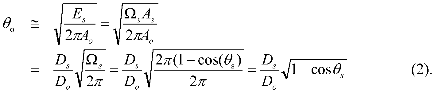
- the directional lamps disclosed herein are constructed based on Equations (2) and (3), so as to match the etendue and skew invariants for the entrance and exit apertures 42, 44. Said another way, the directional lamps disclosed herein are constructed based on Equations (2) and (3) so as to match the etendue and skew invariants for (i) the source light distribution output by the entrance aperture 42 and (ii) the light beam intended to emanate out of the exit aperture 44.
- Equation (2) includes four parameters: output half-angle ⁇ 0 of the beam (which is one-half the desired FWHM angle); half-angle 9 S of the light distribution at the entrance aperture 42; and the entrance and exit aperture diameters D s , D 0 .
- the output half-angle ⁇ 0 of the beam is a target beam half-angle that the directional lamp is to produce, and so it can be considered to be the result of the other 3 parameters.
- Exit aperture D 0 should be made as small as practicable in order to maximize the lateral extent Lp of the heat-sinking fins 52 to promote efficient cooling.
- the half-angle 9 S of the light distribution at the entrance aperture 42 is typically about 60° (corresponding to approximately a Lambertian intensity distribution), so that the most influential design parameters for the optical system are the entrance aperture diameter D s which, together with 9 S , determines the source etendue, and exit aperture diameter D 0 .
- the source etendue should be made as small 236548
- D s and 9 S should be minimized, and the exit aperture diameter D 0 should be maximized.
- these design parameters are to be optimized under constraints including: the maximum aperture diameter D 0 imposed by the MR/PAR/R diameter standard DMR/PAR/R; the heat sinking for the thermal load of LED devices 10 sufficient to generate the desired light beam intensity which imposes a minimum value on the fins lateral extent Lp; a minimum value constraint for the entrance aperture diameter D s imposed by thermal, mechanical, electrical, and optical limits on how closely the LED devices 10 can be spaced on the planar reflective surface 20; and a lower limit on the source half-angle 9 S imposed by the low-profile light-mixing source which does not provide partial collimation by multiple reflections, or by the LED intensity distribution itself.
- a disc light source that is, a light source having a disc-shaped light emission area, optionally discretized into one or more individual LED devices disposed on a reflective circuit board or other support
- a disc light source that is, a light source having a disc-shaped light emission area, optionally discretized into one or more individual LED devices disposed on a reflective circuit board or other support
- the exit aperture 44 enables exact matching of skew invariance with that of the exit aperture 44, which provides the possibility of containing all of the face lumens within the beam lumens in an ideal situation, or nearly all of the face lumens within the beam lumens in a practical lamp, providing the possibility of an extremely abrupt edge of the beam pattern.
- the Fresnel lens 48 (or convex lens, holographic lens, compound lens, or so forth) filling the exit aperture and cooperating with the conical reflector 46 (or other collecting reflector) may be used to generate an image in the optical far field of the illumination output at the entrance aperture 42 to produce a beam pattern with a sharp cut-off at the edge of the beam.
- the Fresnel lens (or convex lens, holographic lens, compound lens, or so forth) cooperating with the conical reflector 46 (or other collecting reflector) may be used to generate an image of the illumination output at the entrance aperture 42 that is de-focused in the far field to produce a beam pattern with a gradual cut-off at the edge of the beam.
- a de-focused placement of the Fresnel lens 48 may also be used to supplement the light mixing that is provided predominantly by the diffuser, since the images of the discrete LED light sources are thus out of focus in the far field such that the interstitial spaces between the LEDs appear in the far-field beam pattern to be filled in by the light from adjacent LEDs.
- the design considerations do not include any limitation on the "height" or "length” of the lamp along the optical axis OA.
- the optical axis OA is defined by the beam forming optical system, and more particularly by the optical axis of the imaging lens 48 in the embodiment of FIGURE 23).
- the only limitation imposed on the height or length is by the focal length of the lens 48, which can be small for a Fresnel lens or a short-focal length convex lens.
- the illustrated conical reflector 46 could be replaced by a parabolic concentrator, a compound parabolic concentrator, or so forth.
- a diffuser 30' is disposed outside the Fresnel lens 48, that is, such that light from the pillbox passes through the Fresnel lens 48 to reach the diffuser 30'.
- the diffuser 30 at the entrance aperture 42 that is, at the "top” of the pillbox
- heavy diffusion is typically employed to achieve adequate light mixing.
- this can lead to back-reflections off the diffuser 30 and consequent increased light losses.
- Adding the diffuser 30' located outside of the Fresnel lens 48 can provide additional light mixing, enabling the diffusion strength of the diffuser 30 at the entrance aperture 42 to be reduced, or the diffuser 30' may provide all of the required light mixing so that the diffuser 30 at the entrance aperture 42 may be eliminated.
- the diffuser 30' located outside the Fresnel lens 48 the incident light rays are nearly collimated, and so the diffuser 30' can be selected to be a diffuser designed to operate at high efficiency (-92%, and more preferably >95%, and still more preferably >98%) for collimated input light.
- the spatial and angular non-uniformity of the luminous intensity and color is mixed to a substantially uniform distribution by the diffuser 30' which is a single-pass light diffuser.
- suitable single-pass light diffusers designed to provide a selected output (diffused) light scattering distribution FWHM include Light Shaping Diffuser ® material produced by Luminit, LLC, having 85-92% transmission of visible light and providing diffusion of the transmitted light with a light scattering distribution (for collimated input light) of between 1° and 80° FWHM, depending on the choice of material.
- Another suitable diffuser material is ACEL TM light diffusing material (available from Bright View Technologies). These illustrative designed single-pass diffuser materials are not bulk diffusers in which light scattering particles are dispersed in a 236548
- the diffuser 30 located beyond the beam-forming optics and engineered to provide a designed light scattering distribution FWHM results in significant increase in overall optical efficiency (>90%).
- the diffuser 30 is included while the diffuser 30' is omitted. In some embodiments, both diffusers 30, 30' are included.
- the diffuser 30 at the entrance aperture 42 is omitted and the diffuser 30' outside the Fresnel lens 48 is included.
- the cone of the reflector 46 is optionally extended to the LED die level - that is, the planar light source 28 is optionally arranged coincident with the entrance aperture 42, and the reflective sidewalls 32 are optionally omitted along with the omitting of the diffuser 30.
- the diffuser 30' is relied upon to provide the light mixing.
- the lens may also be defocused to provide additional light mixing.
- FIGURE 24A diagrammatically shows a lamp containing a light engine LE, beam forming optics BF including a conical reflector and lens, and the optically diffusing element 30 located adjacent an optically reflective side wall.
- the optically diffusing element 30 is a heavy diffuser, and there is no diffuser at the output aperture.
- FIGURE 24B diagrammatically shows a lamp containing the light engine LE, beam forming optics BF including a conical reflector and lens, and both (i) the optically diffusing element 30 located adjacent an optically reflective side wall and (ii) and the optically diffusing element 30' located near the output aperture of the 236548
- FIGURE 24C diagrammatically shows a lamp containing the light engine LE, beam forming optics BF including a conical reflector and lens, and the light shaping optically diffusing element 30' located near the output aperture of the MR/PAR/R lamp. In the embodiment of FIGURE 24C the light diffusing element 30 is omitted.
- FIGURES 25-27 illustrate how the conical reflector 46 can be a planar reflective sheet covering an inside conical surface of a conical former.
- FIGURE 25 shows a planar reflective sheet 46p having rounded lower and upper edges 60, 62 corresponding to the entrance and exit apertures 42, 44, respectively, and side edges 64, 66.
- the planar reflective sheet 46p can be rolled to form the conical reflector 46, with the side edges 64, 66 joined at a connection 68 (which optionally may include some overlap of the side edges 64, 66), which then may be inserted into a conical former 70 as illustrated in FIGURE 27.
- the conical former 70 may, for example, be a conical heat-sinking structure 70 that also supports the heat-sinking fins 52.
- the conical reflector also enables the use of coated reflector materials having extremely high optical reflectivity in the visible, such as a coated aluminum material named Miro produced by ALANOD Aluminium- Veredlung GmbH & Co. KG having about 92-98% visible reflectance; or polymer film named Vikuiti produced by 3M having about 97-98% visible reflectance.
- FIGURES 28 and 29 illustrate computed values for the FWHM angle of the beam pattern in degrees (on the ordinate axis) versus the entrance aperture diameter D s for various MR/PAR/R lamp designs (on the abscissa axis).
- an optical element 100 includes a lensing side 102 that is the light-input side and is engineered by laser etching or another patterning technique to define a Fresnel lens suitably serving as the Fresnel lens 48, and also includes a light diffusing side 104 that is the light exit side and is engineered by laser etching or another patterning technique to define a single-pass interface diffuser suitably serving as the light-mixing diffuser 30'.
- the light mixing diffuser comprises an interface diffuser 104 formed into a principal surface of the lens 100 of the beam forming optical system.
- the diffusing side 104 advantageously passes light after it is formed into a beam by the lensing side 102.
- an optical element 110 has the same structure as the optical element 100, but the light diffusing side 104 is arranged as the light input side and the lensing side 102 is arranged as the light exit side.
Abstract
Description

Claims
Priority Applications (7)
| Application Number | Priority Date | Filing Date | Title |
|---|---|---|---|
| CA2786510A CA2786510C (en) | 2010-01-11 | 2011-01-07 | Compact light-mixing led light engine and white led lamp with narrow beam and high cri using same |
| CN201180013439.2A CN102859257B (en) | 2010-01-11 | 2011-01-07 | Compact mixed light LED light engine and narrow beam white led lamps and use its high CRI |
| BR112012016981A BR112012016981A2 (en) | 2010-01-11 | 2011-01-07 | directional lamp and lighting fixture |
| EP11701707A EP2524163A2 (en) | 2010-01-11 | 2011-01-07 | Compact light-mixing led light engine and white led lamp with narrow beam and high cri using same |
| KR1020127021131A KR101921339B1 (en) | 2010-01-11 | 2011-01-07 | Compact light-mixing led light engine and white led lamp with narrow beam and high cri using same |
| JP2012548131A JP6018920B2 (en) | 2010-01-11 | 2011-01-07 | Small light mixing LED light engine and high CRI narrow beam white LED lamp using small light mixing LED light engine |
| ZA2012/05647A ZA201205647B (en) | 2010-01-11 | 2012-07-26 | Compact light-mixing led light engine and white led lamp with narrow beam and high cri using same |
Applications Claiming Priority (2)
| Application Number | Priority Date | Filing Date | Title |
|---|---|---|---|
| US12/685,287 US8613530B2 (en) | 2010-01-11 | 2010-01-11 | Compact light-mixing LED light engine and white LED lamp with narrow beam and high CRI using same |
| US12/685,287 | 2010-01-11 |
Publications (3)
| Publication Number | Publication Date |
|---|---|
| WO2011085146A2 true WO2011085146A2 (en) | 2011-07-14 |
| WO2011085146A3 WO2011085146A3 (en) | 2011-11-10 |
| WO2011085146A8 WO2011085146A8 (en) | 2012-10-04 |
Family
ID=43795086
Family Applications (1)
| Application Number | Title | Priority Date | Filing Date |
|---|---|---|---|
| PCT/US2011/020442 WO2011085146A2 (en) | 2010-01-11 | 2011-01-07 | Compact light-mixing led light engine and white led lamp with narrow beam and high cri using same |
Country Status (11)
| Country | Link |
|---|---|
| US (2) | US8613530B2 (en) |
| EP (1) | EP2524163A2 (en) |
| JP (1) | JP6018920B2 (en) |
| KR (1) | KR101921339B1 (en) |
| CN (1) | CN102859257B (en) |
| BR (1) | BR112012016981A2 (en) |
| CA (2) | CA2786510C (en) |
| CO (1) | CO6592080A2 (en) |
| TW (1) | TWI576541B (en) |
| WO (1) | WO2011085146A2 (en) |
| ZA (1) | ZA201205647B (en) |
Cited By (4)
| Publication number | Priority date | Publication date | Assignee | Title |
|---|---|---|---|---|
| AT12552U1 (en) * | 2010-12-03 | 2012-07-15 | Tridonic Jennersdorf Gmbh | LED RADIATOR WITH REFLECTOR |
| WO2013055388A2 (en) * | 2011-10-03 | 2013-04-18 | Solais Lighting, Inc. | Led illumination source with improved visual characteristics |
| JP2013118292A (en) * | 2011-12-02 | 2013-06-13 | Citizen Electronics Co Ltd | Led light-emitting device |
| JP2016518026A (en) * | 2013-04-11 | 2016-06-20 | アポトロニクス チャイナ コーポレイション | LED unit module, light emitting device, and light source system |
Families Citing this family (120)
| Publication number | Priority date | Publication date | Assignee | Title |
|---|---|---|---|---|
| DE102009015424B4 (en) * | 2009-03-27 | 2010-12-09 | Oec Ag | lighting device |
| CA2789267A1 (en) * | 2010-02-08 | 2011-08-11 | Ole K. Nilssen | Evaporation cooled lamp |
| US8550647B2 (en) | 2010-06-15 | 2013-10-08 | Micron Technology, Inc. | Solid state lighting device with different illumination parameters at different regions of an emitter array |
| US20120176786A1 (en) * | 2010-07-15 | 2012-07-12 | American Panel Corporation | Shaped Reflectors for Enhanced Optical Diffusion in Backlight Assemblies |
| US8506105B2 (en) | 2010-08-25 | 2013-08-13 | Generla Electric Company | Thermal management systems for solid state lighting and other electronic systems |
| US10267506B2 (en) | 2010-11-22 | 2019-04-23 | Cree, Inc. | Solid state lighting apparatuses with non-uniformly spaced emitters for improved heat distribution, system having the same, and methods having the same |
| US8342715B2 (en) * | 2011-03-16 | 2013-01-01 | Wen-Sung Lee | Lens arrangement for telescopic illuminator |
| DE102011018808A1 (en) * | 2011-04-27 | 2012-10-31 | Osram Opto Semiconductors Gmbh | Lighting device and control device for controlling and / or regulating a plurality of light-emitting diodes |
| US8833980B2 (en) | 2011-05-09 | 2014-09-16 | Cree, Inc. | High efficiency LED lamp |
| US9797589B2 (en) * | 2011-05-09 | 2017-10-24 | Cree, Inc. | High efficiency LED lamp |
| US10094548B2 (en) * | 2011-05-09 | 2018-10-09 | Cree, Inc. | High efficiency LED lamp |
| ITRM20110442A1 (en) * | 2011-08-12 | 2013-02-13 | Sisti Fabio De | OPTICAL SYSTEM FOR LED LIGHT PROJECTORS WITH FRESNEL LENS OR CONVEX FLOOR, IN PARTICULAR FOR SCENOTECHNICAL LIGHTING. |
| US20130099263A1 (en) * | 2011-10-20 | 2013-04-25 | Gregory Lee Heacock | Full spectrum led light source |
| US9171455B1 (en) * | 2011-12-30 | 2015-10-27 | Gary K. MART | Multi-modal wireless controller for controlling an LED lighting system |
| WO2013112435A1 (en) | 2012-01-24 | 2013-08-01 | Cooledge Lighting Inc. | Light - emitting devices having discrete phosphor chips and fabrication methods |
| US8907362B2 (en) | 2012-01-24 | 2014-12-09 | Cooledge Lighting Inc. | Light-emitting dies incorporating wavelength-conversion materials and related methods |
| US8896010B2 (en) | 2012-01-24 | 2014-11-25 | Cooledge Lighting Inc. | Wafer-level flip chip device packages and related methods |
| US9806246B2 (en) | 2012-02-07 | 2017-10-31 | Cree, Inc. | Ceramic-based light emitting diode (LED) devices, components, and methods |
| US9052414B2 (en) | 2012-02-07 | 2015-06-09 | Microsoft Technology Licensing, Llc | Virtual image device |
| US9354748B2 (en) | 2012-02-13 | 2016-05-31 | Microsoft Technology Licensing, Llc | Optical stylus interaction |
| US8749529B2 (en) | 2012-03-01 | 2014-06-10 | Microsoft Corporation | Sensor-in-pixel display system with near infrared filter |
| US9360893B2 (en) | 2012-03-02 | 2016-06-07 | Microsoft Technology Licensing, Llc | Input device writing surface |
| US9460029B2 (en) | 2012-03-02 | 2016-10-04 | Microsoft Technology Licensing, Llc | Pressure sensitive keys |
| US9426905B2 (en) | 2012-03-02 | 2016-08-23 | Microsoft Technology Licensing, Llc | Connection device for computing devices |
| US9064654B2 (en) | 2012-03-02 | 2015-06-23 | Microsoft Technology Licensing, Llc | Method of manufacturing an input device |
| US9870066B2 (en) | 2012-03-02 | 2018-01-16 | Microsoft Technology Licensing, Llc | Method of manufacturing an input device |
| US8873227B2 (en) | 2012-03-02 | 2014-10-28 | Microsoft Corporation | Flexible hinge support layer |
| US9075566B2 (en) | 2012-03-02 | 2015-07-07 | Microsoft Technoogy Licensing, LLC | Flexible hinge spine |
| US9298236B2 (en) | 2012-03-02 | 2016-03-29 | Microsoft Technology Licensing, Llc | Multi-stage power adapter configured to provide a first power level upon initial connection of the power adapter to the host device and a second power level thereafter upon notification from the host device to the power adapter |
| USRE48963E1 (en) | 2012-03-02 | 2022-03-08 | Microsoft Technology Licensing, Llc | Connection device for computing devices |
| US9022601B2 (en) * | 2012-04-09 | 2015-05-05 | Cree, Inc. | Optical element including texturing to control beam width and color mixing |
| US9456478B2 (en) | 2012-04-23 | 2016-09-27 | Abl Ip Holding Llc | System and method for controlling LED segments to provide lighting effects |
| CN103375736A (en) * | 2012-04-28 | 2013-10-30 | Ge医疗系统环球技术有限公司 | Light-emitting diode (LED) lamp, beam-defining clipper comprising same and X-ray device |
| US20130300590A1 (en) | 2012-05-14 | 2013-11-14 | Paul Henry Dietz | Audio Feedback |
| TWM441214U (en) * | 2012-06-07 | 2012-11-11 | Lextar Electronics Corp | Light source module |
| US10031556B2 (en) | 2012-06-08 | 2018-07-24 | Microsoft Technology Licensing, Llc | User experience adaptation |
| US9019615B2 (en) | 2012-06-12 | 2015-04-28 | Microsoft Technology Licensing, Llc | Wide field-of-view virtual image projector |
| US9355345B2 (en) | 2012-07-23 | 2016-05-31 | Microsoft Technology Licensing, Llc | Transparent tags with encoded data |
| CN103574479B (en) * | 2012-07-24 | 2015-04-15 | 旭正隆股份有限公司 | LED light projector |
| US8964379B2 (en) | 2012-08-20 | 2015-02-24 | Microsoft Corporation | Switchable magnetic lock |
| US9388947B2 (en) * | 2012-08-28 | 2016-07-12 | Cree, Inc. | Lighting device including spatially segregated lumiphor and reflector arrangement |
| WO2014046736A1 (en) * | 2012-09-18 | 2014-03-27 | Wavien, Inc. | Lamp system having parabolic reflector with two reflections for recycling light |
| US9127818B2 (en) | 2012-10-03 | 2015-09-08 | Lighting Science Group Corporation | Elongated LED luminaire and associated methods |
| US9152173B2 (en) | 2012-10-09 | 2015-10-06 | Microsoft Technology Licensing, Llc | Transparent display device |
| US9513748B2 (en) | 2012-12-13 | 2016-12-06 | Microsoft Technology Licensing, Llc | Combined display panel circuit |
| WO2014099334A1 (en) * | 2012-12-18 | 2014-06-26 | Musco Corporation | Multi-led lens with light pattern optimization |
| US9690029B2 (en) | 2013-01-30 | 2017-06-27 | Cree, Inc. | Optical waveguides and luminaires incorporating same |
| US9519095B2 (en) | 2013-01-30 | 2016-12-13 | Cree, Inc. | Optical waveguides |
| US9291320B2 (en) | 2013-01-30 | 2016-03-22 | Cree, Inc. | Consolidated troffer |
| EP2951497B1 (en) * | 2013-01-30 | 2020-01-29 | Ideal Industries Lighting Llc | Light engine |
| US9442243B2 (en) | 2013-01-30 | 2016-09-13 | Cree, Inc. | Waveguide bodies including redirection features and methods of producing same |
| US9625638B2 (en) | 2013-03-15 | 2017-04-18 | Cree, Inc. | Optical waveguide body |
| US9869432B2 (en) | 2013-01-30 | 2018-01-16 | Cree, Inc. | Luminaires using waveguide bodies and optical elements |
| US9366396B2 (en) | 2013-01-30 | 2016-06-14 | Cree, Inc. | Optical waveguide and lamp including same |
| US9411086B2 (en) | 2013-01-30 | 2016-08-09 | Cree, Inc. | Optical waveguide assembly and light engine including same |
| US9638835B2 (en) | 2013-03-05 | 2017-05-02 | Microsoft Technology Licensing, Llc | Asymmetric aberration correcting lens |
| KR20140111419A (en) * | 2013-03-11 | 2014-09-19 | 삼성전자주식회사 | Lighting of light emitting diode and method for manufacturing the lighting |
| US10379278B2 (en) * | 2013-03-15 | 2019-08-13 | Ideal Industries Lighting Llc | Outdoor and/or enclosed structure LED luminaire outdoor and/or enclosed structure LED luminaire having outward illumination |
| US10502899B2 (en) * | 2013-03-15 | 2019-12-10 | Ideal Industries Lighting Llc | Outdoor and/or enclosed structure LED luminaire |
| US10400984B2 (en) | 2013-03-15 | 2019-09-03 | Cree, Inc. | LED light fixture and unitary optic member therefor |
| US9798072B2 (en) | 2013-03-15 | 2017-10-24 | Cree, Inc. | Optical element and method of forming an optical element |
| US9920901B2 (en) | 2013-03-15 | 2018-03-20 | Cree, Inc. | LED lensing arrangement |
| US9366799B2 (en) | 2013-03-15 | 2016-06-14 | Cree, Inc. | Optical waveguide bodies and luminaires utilizing same |
| US10436970B2 (en) | 2013-03-15 | 2019-10-08 | Ideal Industries Lighting Llc | Shaped optical waveguide bodies |
| US10209429B2 (en) | 2013-03-15 | 2019-02-19 | Cree, Inc. | Luminaire with selectable luminous intensity pattern |
| US9304549B2 (en) | 2013-03-28 | 2016-04-05 | Microsoft Technology Licensing, Llc | Hinge mechanism for rotatable component attachment |
| FR3006454B1 (en) * | 2013-05-31 | 2015-11-20 | Inst Optique | DEVICE FOR CREATING LIGHT EFFECTS |
| CN203478109U (en) * | 2013-07-22 | 2014-03-12 | 欧司朗有限公司 | Optical structure for multiple light sources |
| JP6107514B2 (en) * | 2013-07-30 | 2017-04-05 | 株式会社デンソー | Display device |
| EP3052981A2 (en) * | 2013-10-01 | 2016-08-10 | Robe Lighting, Inc | Multiple color homogenization system for an led luminaire |
| KR101504251B1 (en) * | 2013-11-21 | 2015-03-19 | 현대모비스 주식회사 | Laser Optic Module |
| US9255673B2 (en) * | 2013-12-27 | 2016-02-09 | Switch Bulb Company, Inc. | LED bulb having an adjustable light-distribution profile |
| CN104968991A (en) * | 2014-01-02 | 2015-10-07 | 皇家飞利浦有限公司 | Light emitting module |
| EP2935980B1 (en) * | 2014-01-02 | 2016-06-15 | Philips Lighting Holding B.V. | Light emitting module |
| US9317072B2 (en) | 2014-01-28 | 2016-04-19 | Microsoft Technology Licensing, Llc | Hinge mechanism with preset positions |
| WO2015119858A1 (en) | 2014-02-05 | 2015-08-13 | Cooledge Lighting Inc. | Light-emitting dies incorporating wavelength-conversion materials and related methods |
| WO2015136625A1 (en) * | 2014-03-11 | 2015-09-17 | 堺ディスプレイプロダクト株式会社 | Light source apparatus, display apparatus, and light source apparatus manufacturing method |
| US10120420B2 (en) | 2014-03-21 | 2018-11-06 | Microsoft Technology Licensing, Llc | Lockable display and techniques enabling use of lockable displays |
| DE102014104339B4 (en) * | 2014-03-27 | 2017-06-08 | Osram Gmbh | Central brightening element for LED lights |
| EP3149397A1 (en) * | 2014-05-30 | 2017-04-05 | Osram Sylvania Inc. | Hybrid optical systems including flexible optical systems and light control films |
| US10324733B2 (en) | 2014-07-30 | 2019-06-18 | Microsoft Technology Licensing, Llc | Shutdown notifications |
| TW201608172A (en) * | 2014-08-21 | 2016-03-01 | 晟大國際股份有限公司 | LED illumination apparatus |
| US9424048B2 (en) | 2014-09-15 | 2016-08-23 | Microsoft Technology Licensing, Llc | Inductive peripheral retention device |
| US9447620B2 (en) | 2014-09-30 | 2016-09-20 | Microsoft Technology Licensing, Llc | Hinge mechanism with multiple preset positions |
| US9826581B2 (en) | 2014-12-05 | 2017-11-21 | Cree, Inc. | Voltage configurable solid state lighting apparatuses, systems, and related methods |
| US10352532B2 (en) * | 2014-12-17 | 2019-07-16 | Ledvance Llc | Uniform light source with variable beam divergence |
| US20160230938A1 (en) * | 2015-02-10 | 2016-08-11 | Crownmate Technology Co., Ltd. | Omnidirectional light-emitting diode light bulb |
| JP2016162693A (en) * | 2015-03-04 | 2016-09-05 | パナソニックIpマネジメント株式会社 | Lighting device |
| CN107667253B (en) * | 2015-05-20 | 2020-03-06 | 飞利浦照明控股有限公司 | Illumination device, lens and method |
| US9752361B2 (en) | 2015-06-18 | 2017-09-05 | Microsoft Technology Licensing, Llc | Multistage hinge |
| US9864415B2 (en) | 2015-06-30 | 2018-01-09 | Microsoft Technology Licensing, Llc | Multistage friction hinge |
| JP6583813B2 (en) * | 2015-07-30 | 2019-10-02 | パナソニックIpマネジメント株式会社 | Light source and illumination device using the light source |
| US9512978B1 (en) | 2015-08-13 | 2016-12-06 | Randal L Wimberly | Vortex light projection system, LED lensless primary optics system, and perfectly random LED color mixing system |
| US9844114B2 (en) | 2015-12-09 | 2017-12-12 | Alb Ip Holding Llc | Color mixing for solid state lighting using direct AC drives |
| US10132992B2 (en) | 2016-03-20 | 2018-11-20 | Robe Lighting S.R.O. | Special flower effects beam and washlight luminaire |
| US10162105B2 (en) * | 2016-03-20 | 2018-12-25 | Robe Lighting S.R.O. | Wash light luminaire with special effects capabilities |
| KR20170110476A (en) * | 2016-03-23 | 2017-10-11 | 엘지이노텍 주식회사 | Optical module |
| US10344797B2 (en) | 2016-04-05 | 2019-07-09 | Microsoft Technology Licensing, Llc | Hinge with multiple preset positions |
| US11719882B2 (en) | 2016-05-06 | 2023-08-08 | Ideal Industries Lighting Llc | Waveguide-based light sources with dynamic beam shaping |
| US10416377B2 (en) | 2016-05-06 | 2019-09-17 | Cree, Inc. | Luminaire with controllable light emission |
| US9854637B2 (en) | 2016-05-18 | 2017-12-26 | Abl Ip Holding Llc | Method for controlling a tunable white fixture using a single handle |
| JP2017216061A (en) * | 2016-05-30 | 2017-12-07 | ミネベアミツミ株式会社 | Lighting device |
| US10037057B2 (en) | 2016-09-22 | 2018-07-31 | Microsoft Technology Licensing, Llc | Friction hinge |
| EP3559991B1 (en) | 2016-12-21 | 2020-09-30 | Lumileds Holding B.V. | Led array module |
| WO2018114527A1 (en) * | 2016-12-21 | 2018-06-28 | Lumileds Holding B.V. | Led array module |
| WO2018125935A1 (en) | 2016-12-27 | 2018-07-05 | DePuy Synthes Products, Inc. | Systems, methods, and devices for providing illumination in an endoscopic imaging environment |
| US10415766B2 (en) * | 2017-02-28 | 2019-09-17 | Feit Electric Company, Inc. | Backlit lamp having directional light source |
| WO2018157903A1 (en) * | 2017-02-28 | 2018-09-07 | Coelux S.R.L. | Sunlight-based large area light source and large area luminaire |
| JP6888458B2 (en) * | 2017-07-25 | 2021-06-16 | セイコーエプソン株式会社 | Lighting equipment and projectors |
| US10774994B2 (en) * | 2017-08-17 | 2020-09-15 | Leedarson America Inc. | Spotlight apparatus and manufacturing method thereof |
| CN108302493A (en) * | 2017-10-17 | 2018-07-20 | 上海小糸车灯有限公司 | A kind of car light optical texture changing light source diffusion angle |
| JP7020233B2 (en) * | 2018-03-27 | 2022-02-16 | 東芝ライテック株式会社 | Lighting equipment |
| CA3042098A1 (en) * | 2018-05-02 | 2019-11-02 | Hubbell Incorporated | Systems and methods for assembling a light engine |
| CN112639358B (en) | 2018-09-03 | 2023-07-14 | 昕诺飞控股有限公司 | Reflector and starting sheet for forming the reflector |
| US10874006B1 (en) | 2019-03-08 | 2020-12-22 | Abl Ip Holding Llc | Lighting fixture controller for controlling color temperature and intensity |
| US10728979B1 (en) | 2019-09-30 | 2020-07-28 | Abl Ip Holding Llc | Lighting fixture configured to provide multiple lighting effects |
| USD973237S1 (en) | 2021-01-11 | 2022-12-20 | Steven James SELAK | Lighting device |
| USD999409S1 (en) | 2021-01-15 | 2023-09-19 | Steven James SELAK | Light emitting diode device |
| US11448390B2 (en) | 2021-02-18 | 2022-09-20 | Steven James SELAK | Waterproof light bulb assembly |
| US11408573B1 (en) | 2021-09-23 | 2022-08-09 | Blisslights Llc | Optical projection device |
Citations (3)
| Publication number | Priority date | Publication date | Assignee | Title |
|---|---|---|---|---|
| US7213940B1 (en) | 2005-12-21 | 2007-05-08 | Led Lighting Fixtures, Inc. | Lighting device and lighting method |
| US7224000B2 (en) | 2002-08-30 | 2007-05-29 | Lumination, Llc | Light emitting diode component |
| US20090103296A1 (en) | 2007-10-17 | 2009-04-23 | Xicato, Inc. | Illumination Device with Light Emitting Diodes |
Family Cites Families (45)
| Publication number | Priority date | Publication date | Assignee | Title |
|---|---|---|---|---|
| JP2715109B2 (en) | 1988-09-09 | 1998-02-18 | 東邦チタニウム株式会社 | Catalyst for polymerization of olefins |
| US5296724A (en) | 1990-04-27 | 1994-03-22 | Omron Corporation | Light emitting semiconductor device having an optical element |
| JPH04226095A (en) * | 1990-04-27 | 1992-08-14 | Omron Corp | Semiconductor light emitting device |
| US5174649B1 (en) * | 1991-07-17 | 1998-04-14 | Precision Solar Controls Inc | Led lamp including refractive lens element |
| JP3931355B2 (en) | 1995-09-06 | 2007-06-13 | 日亜化学工業株式会社 | Planar light source |
| US6633120B2 (en) | 1998-11-19 | 2003-10-14 | Unisplay S.A. | LED lamps |
| US6273589B1 (en) | 1999-01-29 | 2001-08-14 | Agilent Technologies, Inc. | Solid state illumination source utilizing dichroic reflectors |
| US6212213B1 (en) | 1999-01-29 | 2001-04-03 | Agilent Technologies, Inc. | Projector light source utilizing a solid state green light source |
| JP2001144331A (en) | 1999-09-02 | 2001-05-25 | Toyoda Gosei Co Ltd | Light-emitting device |
| US20020176259A1 (en) | 1999-11-18 | 2002-11-28 | Ducharme Alfred D. | Systems and methods for converting illumination |
| US6513949B1 (en) | 1999-12-02 | 2003-02-04 | Koninklijke Philips Electronics N.V. | LED/phosphor-LED hybrid lighting systems |
| US6547416B2 (en) * | 2000-12-21 | 2003-04-15 | Koninklijke Philips Electronics N.V. | Faceted multi-chip package to provide a beam of uniform white light from multiple monochrome LEDs |
| US6616299B2 (en) * | 2001-02-02 | 2003-09-09 | Gelcore Llc | Single optical element LED signal |
| WO2002065427A1 (en) * | 2001-02-09 | 2002-08-22 | Nichia Corporation | Led indication lamp |
| JP2003005677A (en) * | 2001-06-20 | 2003-01-08 | Fujitsu General Ltd | Led display unit |
| US6485160B1 (en) | 2001-06-25 | 2002-11-26 | Gelcore Llc | Led flashlight with lens |
| US6641284B2 (en) | 2002-02-21 | 2003-11-04 | Whelen Engineering Company, Inc. | LED light assembly |
| JP2004022257A (en) * | 2002-06-14 | 2004-01-22 | Kyocera Corp | Led illumination apparatus |
| US20040184272A1 (en) | 2003-03-20 | 2004-09-23 | Wright Steven A. | Substrate for light-emitting diode (LED) mounting including heat dissipation structures, and lighting assembly including same |
| US20070001177A1 (en) | 2003-05-08 | 2007-01-04 | Koninklijke Philips Electronics N.V. | Integrated light-emitting diode system |
| US7145125B2 (en) | 2003-06-23 | 2006-12-05 | Advanced Optical Technologies, Llc | Integrating chamber cone light using LED sources |
| US6942360B2 (en) | 2003-10-01 | 2005-09-13 | Enertron, Inc. | Methods and apparatus for an LED light engine |
| EP1794640B1 (en) | 2004-09-24 | 2014-02-26 | Koninklijke Philips N.V. | Illumination system |
| ES2368839T3 (en) * | 2004-09-24 | 2011-11-22 | Koninklijke Philips Electronics N.V. | LIGHTING SYSTEM. |
| US7125160B2 (en) * | 2004-10-29 | 2006-10-24 | Applied Innovative Technologies, Inc. | Led light collection and uniform transmission system using a conical reflector with a roughed up inner surface |
| JP4640248B2 (en) | 2005-07-25 | 2011-03-02 | 豊田合成株式会社 | Light source device |
| US20070236121A1 (en) | 2006-04-06 | 2007-10-11 | Lei Deng | High-intensity discharge lamp for spot lighting |
| CN101454613A (en) | 2006-05-31 | 2009-06-10 | 科锐Led照明科技公司 | Lighting device with color control, and method of lighting |
| KR20090082449A (en) | 2006-10-31 | 2009-07-30 | 티아이알 테크놀로지 엘피 | Light source comprising a light-excitable medium |
| US9441793B2 (en) | 2006-12-01 | 2016-09-13 | Cree, Inc. | High efficiency lighting device including one or more solid state light emitters, and method of lighting |
| JP2008218089A (en) * | 2007-03-01 | 2008-09-18 | Mitsubishi Electric Corp | Lighting system |
| EP1995510A1 (en) | 2007-05-25 | 2008-11-26 | Hong Kuan Technology Co., Ltd. | LED lamp |
| US8403531B2 (en) | 2007-05-30 | 2013-03-26 | Cree, Inc. | Lighting device and method of lighting |
| US7942556B2 (en) | 2007-06-18 | 2011-05-17 | Xicato, Inc. | Solid state illumination device |
| JP5311779B2 (en) * | 2007-08-21 | 2013-10-09 | シチズン電子株式会社 | LED light emitting device |
| CN101373049A (en) * | 2007-08-24 | 2009-02-25 | 富士迈半导体精密工业(上海)有限公司 | LED lighting device |
| JP4569683B2 (en) | 2007-10-16 | 2010-10-27 | 東芝ライテック株式会社 | Light emitting element lamp and lighting apparatus |
| US7984999B2 (en) | 2007-10-17 | 2011-07-26 | Xicato, Inc. | Illumination device with light emitting diodes and moveable light adjustment member |
| US8376577B2 (en) | 2007-11-05 | 2013-02-19 | Xicato, Inc. | Modular solid state lighting device |
| JP5292790B2 (en) | 2007-12-06 | 2013-09-18 | 東芝ライテック株式会社 | Lighting device |
| JP4988538B2 (en) * | 2007-12-25 | 2012-08-01 | パナソニック株式会社 | Spotlight |
| TWM344443U (en) * | 2008-04-11 | 2008-11-11 | Cosmotac Co Ltd | A flexible reflecting sheet and light structures applying thereof |
| US7986102B2 (en) | 2008-09-12 | 2011-07-26 | General Electric Company | Adjustable color solid state lighting |
| JP2010251213A (en) * | 2009-04-17 | 2010-11-04 | Toshiba Lighting & Technology Corp | Light-emitting module and lighting device |
| CA2763241C (en) * | 2009-05-28 | 2018-02-27 | Koninklijke Philips Electronics N.V. | Illumination device with an envelope enclosing a light source |
-
2010
- 2010-01-11 US US12/685,287 patent/US8613530B2/en active Active
-
2011
- 2011-01-07 CA CA2786510A patent/CA2786510C/en active Active
- 2011-01-07 KR KR1020127021131A patent/KR101921339B1/en active IP Right Grant
- 2011-01-07 EP EP11701707A patent/EP2524163A2/en not_active Withdrawn
- 2011-01-07 JP JP2012548131A patent/JP6018920B2/en active Active
- 2011-01-07 CA CA3060689A patent/CA3060689C/en active Active
- 2011-01-07 WO PCT/US2011/020442 patent/WO2011085146A2/en active Application Filing
- 2011-01-07 BR BR112012016981A patent/BR112012016981A2/en not_active Application Discontinuation
- 2011-01-07 CN CN201180013439.2A patent/CN102859257B/en active Active
- 2011-01-11 TW TW100100986A patent/TWI576541B/en not_active IP Right Cessation
-
2012
- 2012-07-26 ZA ZA2012/05647A patent/ZA201205647B/en unknown
- 2012-08-10 CO CO12135132A patent/CO6592080A2/en active IP Right Grant
-
2013
- 2013-11-19 US US14/083,597 patent/US9534743B2/en active Active
Patent Citations (3)
| Publication number | Priority date | Publication date | Assignee | Title |
|---|---|---|---|---|
| US7224000B2 (en) | 2002-08-30 | 2007-05-29 | Lumination, Llc | Light emitting diode component |
| US7213940B1 (en) | 2005-12-21 | 2007-05-08 | Led Lighting Fixtures, Inc. | Lighting device and lighting method |
| US20090103296A1 (en) | 2007-10-17 | 2009-04-23 | Xicato, Inc. | Illumination Device with Light Emitting Diodes |
Non-Patent Citations (2)
| Title |
|---|
| ROLAND WINSTON: "Non-Imaging Optics", 2005, ELSEVIER ACADEMIC PRESS, pages: 11 |
| ROLAND WINSTON: "Non-Imaging Optics", 2005, ELSEVIER ACADEMIC PRESS, pages: 237 |
Cited By (8)
| Publication number | Priority date | Publication date | Assignee | Title |
|---|---|---|---|---|
| AT12552U1 (en) * | 2010-12-03 | 2012-07-15 | Tridonic Jennersdorf Gmbh | LED RADIATOR WITH REFLECTOR |
| WO2013055388A2 (en) * | 2011-10-03 | 2013-04-18 | Solais Lighting, Inc. | Led illumination source with improved visual characteristics |
| WO2013055388A3 (en) * | 2011-10-03 | 2013-08-22 | Solais Lighting, Inc. | Led illumination source with improved visual characteristics |
| US8579470B1 (en) | 2011-10-03 | 2013-11-12 | Solais Lighting, Inc. | LED illumination source with improved visual characteristics |
| JP2013118292A (en) * | 2011-12-02 | 2013-06-13 | Citizen Electronics Co Ltd | Led light-emitting device |
| US9335035B2 (en) | 2011-12-02 | 2016-05-10 | Citizen Electronics Co., Ltd. | Lighting device including light-emitting element |
| JP2016518026A (en) * | 2013-04-11 | 2016-06-20 | アポトロニクス チャイナ コーポレイション | LED unit module, light emitting device, and light source system |
| US9970628B2 (en) | 2013-04-11 | 2018-05-15 | Appotronics China Corporation | LED unit module, light-emitting device, and light source system |
Also Published As
| Publication number | Publication date |
|---|---|
| JP6018920B2 (en) | 2016-11-02 |
| CA3060689C (en) | 2021-09-28 |
| JP2013516744A (en) | 2013-05-13 |
| CA3060689A1 (en) | 2011-07-14 |
| CN102859257A (en) | 2013-01-02 |
| US20110170289A1 (en) | 2011-07-14 |
| CO6592080A2 (en) | 2013-01-02 |
| EP2524163A2 (en) | 2012-11-21 |
| CA2786510C (en) | 2020-03-10 |
| TWI576541B (en) | 2017-04-01 |
| CA2786510A1 (en) | 2011-07-14 |
| US8613530B2 (en) | 2013-12-24 |
| WO2011085146A8 (en) | 2012-10-04 |
| WO2011085146A3 (en) | 2011-11-10 |
| TW201144696A (en) | 2011-12-16 |
| KR101921339B1 (en) | 2018-11-22 |
| BR112012016981A2 (en) | 2016-04-12 |
| US20140198507A1 (en) | 2014-07-17 |
| US9534743B2 (en) | 2017-01-03 |
| KR20130020654A (en) | 2013-02-27 |
| CN102859257B (en) | 2016-01-27 |
| ZA201205647B (en) | 2014-01-29 |
Similar Documents
| Publication | Publication Date | Title |
|---|---|---|
| US9534743B2 (en) | Directional lamp with beam forming optical system including a lens and collecting reflector | |
| US10962199B2 (en) | Solid state lighting components | |
| US9470882B2 (en) | Optical arrangement for a solid-state lamp | |
| US8322896B2 (en) | Solid-state light bulb | |
| EP2649484B1 (en) | High efficiency total internal reflection optic for solid state lighting luminaires | |
| US8414151B2 (en) | Light emitting diode (LED) based lamp | |
| JP5396278B2 (en) | Method and apparatus for providing uniform projection illumination | |
| US8764224B2 (en) | Luminaire with distributed LED sources | |
| JP6217972B2 (en) | lighting equipment | |
| WO2012024011A1 (en) | Compact led light engine with reflector cups and highly directional lamps using same | |
| AU2010300448B8 (en) | Light emitting diode (LED) based lamp | |
| JP2013045530A (en) | Light emitting device and lighting fixture | |
| AU2015203255B2 (en) | Light emitting diode (LED) based lamp | |
| JP2020077551A (en) | Luminaire | |
| WO2014094349A1 (en) | Led packaging structure |
Legal Events
| Date | Code | Title | Description |
|---|---|---|---|
| WWE | Wipo information: entry into national phase |
Ref document number: 201180013439.2 Country of ref document: CN |
|
| 121 | Ep: the epo has been informed by wipo that ep was designated in this application |
Ref document number: 11701707 Country of ref document: EP Kind code of ref document: A1 |
|
| ENP | Entry into the national phase |
Ref document number: 2786510 Country of ref document: CA |
|
| WWE | Wipo information: entry into national phase |
Ref document number: 2012548131 Country of ref document: JP |
|
| NENP | Non-entry into the national phase |
Ref country code: DE |
|
| WWE | Wipo information: entry into national phase |
Ref document number: 2011701707 Country of ref document: EP |
|
| ENP | Entry into the national phase |
Ref document number: 20127021131 Country of ref document: KR Kind code of ref document: A |
|
| WWE | Wipo information: entry into national phase |
Ref document number: 12135132 Country of ref document: CO |
|
| REG | Reference to national code |
Ref country code: BR Ref legal event code: B01A Ref document number: 112012016981 Country of ref document: BR |
|
| ENP | Entry into the national phase |
Ref document number: 112012016981 Country of ref document: BR Kind code of ref document: A2 Effective date: 20120710 |