WO2011037732A2 - Activatable adhesive, labels, and related methods - Google Patents
Activatable adhesive, labels, and related methods Download PDFInfo
- Publication number
- WO2011037732A2 WO2011037732A2 PCT/US2010/047428 US2010047428W WO2011037732A2 WO 2011037732 A2 WO2011037732 A2 WO 2011037732A2 US 2010047428 W US2010047428 W US 2010047428W WO 2011037732 A2 WO2011037732 A2 WO 2011037732A2
- Authority
- WO
- WIPO (PCT)
- Prior art keywords
- adhesive
- label
- activatable
- base polymer
- layer
- Prior art date
Links
Classifications
-
- C—CHEMISTRY; METALLURGY
- C09—DYES; PAINTS; POLISHES; NATURAL RESINS; ADHESIVES; COMPOSITIONS NOT OTHERWISE PROVIDED FOR; APPLICATIONS OF MATERIALS NOT OTHERWISE PROVIDED FOR
- C09J—ADHESIVES; NON-MECHANICAL ASPECTS OF ADHESIVE PROCESSES IN GENERAL; ADHESIVE PROCESSES NOT PROVIDED FOR ELSEWHERE; USE OF MATERIALS AS ADHESIVES
- C09J133/00—Adhesives based on homopolymers or copolymers of compounds having one or more unsaturated aliphatic radicals, each having only one carbon-to-carbon double bond, and at least one being terminated by only one carboxyl radical, or of salts, anhydrides, esters, amides, imides, or nitriles thereof; Adhesives based on derivatives of such polymers
-
- C—CHEMISTRY; METALLURGY
- C09—DYES; PAINTS; POLISHES; NATURAL RESINS; ADHESIVES; COMPOSITIONS NOT OTHERWISE PROVIDED FOR; APPLICATIONS OF MATERIALS NOT OTHERWISE PROVIDED FOR
- C09J—ADHESIVES; NON-MECHANICAL ASPECTS OF ADHESIVE PROCESSES IN GENERAL; ADHESIVE PROCESSES NOT PROVIDED FOR ELSEWHERE; USE OF MATERIALS AS ADHESIVES
- C09J7/00—Adhesives in the form of films or foils
- C09J7/30—Adhesives in the form of films or foils characterised by the adhesive composition
- C09J7/35—Heat-activated
-
- B—PERFORMING OPERATIONS; TRANSPORTING
- B32—LAYERED PRODUCTS
- B32B—LAYERED PRODUCTS, i.e. PRODUCTS BUILT-UP OF STRATA OF FLAT OR NON-FLAT, e.g. CELLULAR OR HONEYCOMB, FORM
- B32B37/00—Methods or apparatus for laminating, e.g. by curing or by ultrasonic bonding
- B32B37/06—Methods or apparatus for laminating, e.g. by curing or by ultrasonic bonding characterised by the heating method
-
- C—CHEMISTRY; METALLURGY
- C09—DYES; PAINTS; POLISHES; NATURAL RESINS; ADHESIVES; COMPOSITIONS NOT OTHERWISE PROVIDED FOR; APPLICATIONS OF MATERIALS NOT OTHERWISE PROVIDED FOR
- C09J—ADHESIVES; NON-MECHANICAL ASPECTS OF ADHESIVE PROCESSES IN GENERAL; ADHESIVE PROCESSES NOT PROVIDED FOR ELSEWHERE; USE OF MATERIALS AS ADHESIVES
- C09J11/00—Features of adhesives not provided for in group C09J9/00, e.g. additives
- C09J11/02—Non-macromolecular additives
- C09J11/04—Non-macromolecular additives inorganic
-
- C—CHEMISTRY; METALLURGY
- C09—DYES; PAINTS; POLISHES; NATURAL RESINS; ADHESIVES; COMPOSITIONS NOT OTHERWISE PROVIDED FOR; APPLICATIONS OF MATERIALS NOT OTHERWISE PROVIDED FOR
- C09J—ADHESIVES; NON-MECHANICAL ASPECTS OF ADHESIVE PROCESSES IN GENERAL; ADHESIVE PROCESSES NOT PROVIDED FOR ELSEWHERE; USE OF MATERIALS AS ADHESIVES
- C09J133/00—Adhesives based on homopolymers or copolymers of compounds having one or more unsaturated aliphatic radicals, each having only one carbon-to-carbon double bond, and at least one being terminated by only one carboxyl radical, or of salts, anhydrides, esters, amides, imides, or nitriles thereof; Adhesives based on derivatives of such polymers
- C09J133/04—Homopolymers or copolymers of esters
- C09J133/06—Homopolymers or copolymers of esters of esters containing only carbon, hydrogen and oxygen, the oxygen atom being present only as part of the carboxyl radical
- C09J133/08—Homopolymers or copolymers of acrylic acid esters
-
- C—CHEMISTRY; METALLURGY
- C09—DYES; PAINTS; POLISHES; NATURAL RESINS; ADHESIVES; COMPOSITIONS NOT OTHERWISE PROVIDED FOR; APPLICATIONS OF MATERIALS NOT OTHERWISE PROVIDED FOR
- C09J—ADHESIVES; NON-MECHANICAL ASPECTS OF ADHESIVE PROCESSES IN GENERAL; ADHESIVE PROCESSES NOT PROVIDED FOR ELSEWHERE; USE OF MATERIALS AS ADHESIVES
- C09J7/00—Adhesives in the form of films or foils
- C09J7/20—Adhesives in the form of films or foils characterised by their carriers
- C09J7/21—Paper; Textile fabrics
-
- C—CHEMISTRY; METALLURGY
- C09—DYES; PAINTS; POLISHES; NATURAL RESINS; ADHESIVES; COMPOSITIONS NOT OTHERWISE PROVIDED FOR; APPLICATIONS OF MATERIALS NOT OTHERWISE PROVIDED FOR
- C09J—ADHESIVES; NON-MECHANICAL ASPECTS OF ADHESIVE PROCESSES IN GENERAL; ADHESIVE PROCESSES NOT PROVIDED FOR ELSEWHERE; USE OF MATERIALS AS ADHESIVES
- C09J7/00—Adhesives in the form of films or foils
- C09J7/20—Adhesives in the form of films or foils characterised by their carriers
- C09J7/22—Plastics; Metallised plastics
-
- C—CHEMISTRY; METALLURGY
- C09—DYES; PAINTS; POLISHES; NATURAL RESINS; ADHESIVES; COMPOSITIONS NOT OTHERWISE PROVIDED FOR; APPLICATIONS OF MATERIALS NOT OTHERWISE PROVIDED FOR
- C09J—ADHESIVES; NON-MECHANICAL ASPECTS OF ADHESIVE PROCESSES IN GENERAL; ADHESIVE PROCESSES NOT PROVIDED FOR ELSEWHERE; USE OF MATERIALS AS ADHESIVES
- C09J7/00—Adhesives in the form of films or foils
- C09J7/30—Adhesives in the form of films or foils characterised by the adhesive composition
-
- G—PHYSICS
- G09—EDUCATION; CRYPTOGRAPHY; DISPLAY; ADVERTISING; SEALS
- G09F—DISPLAYING; ADVERTISING; SIGNS; LABELS OR NAME-PLATES; SEALS
- G09F3/00—Labels, tag tickets, or similar identification or indication means; Seals; Postage or like stamps
- G09F3/08—Fastening or securing by means not forming part of the material of the label itself
- G09F3/10—Fastening or securing by means not forming part of the material of the label itself by an adhesive layer
-
- C—CHEMISTRY; METALLURGY
- C09—DYES; PAINTS; POLISHES; NATURAL RESINS; ADHESIVES; COMPOSITIONS NOT OTHERWISE PROVIDED FOR; APPLICATIONS OF MATERIALS NOT OTHERWISE PROVIDED FOR
- C09J—ADHESIVES; NON-MECHANICAL ASPECTS OF ADHESIVE PROCESSES IN GENERAL; ADHESIVE PROCESSES NOT PROVIDED FOR ELSEWHERE; USE OF MATERIALS AS ADHESIVES
- C09J2203/00—Applications of adhesives in processes or use of adhesives in the form of films or foils
- C09J2203/334—Applications of adhesives in processes or use of adhesives in the form of films or foils as a label
-
- C—CHEMISTRY; METALLURGY
- C09—DYES; PAINTS; POLISHES; NATURAL RESINS; ADHESIVES; COMPOSITIONS NOT OTHERWISE PROVIDED FOR; APPLICATIONS OF MATERIALS NOT OTHERWISE PROVIDED FOR
- C09J—ADHESIVES; NON-MECHANICAL ASPECTS OF ADHESIVE PROCESSES IN GENERAL; ADHESIVE PROCESSES NOT PROVIDED FOR ELSEWHERE; USE OF MATERIALS AS ADHESIVES
- C09J2301/00—Additional features of adhesives in the form of films or foils
- C09J2301/30—Additional features of adhesives in the form of films or foils characterized by the chemical, physicochemical or physical properties of the adhesive or the carrier
- C09J2301/304—Additional features of adhesives in the form of films or foils characterized by the chemical, physicochemical or physical properties of the adhesive or the carrier the adhesive being heat-activatable, i.e. not tacky at temperatures inferior to 30°C
-
- C—CHEMISTRY; METALLURGY
- C09—DYES; PAINTS; POLISHES; NATURAL RESINS; ADHESIVES; COMPOSITIONS NOT OTHERWISE PROVIDED FOR; APPLICATIONS OF MATERIALS NOT OTHERWISE PROVIDED FOR
- C09J—ADHESIVES; NON-MECHANICAL ASPECTS OF ADHESIVE PROCESSES IN GENERAL; ADHESIVE PROCESSES NOT PROVIDED FOR ELSEWHERE; USE OF MATERIALS AS ADHESIVES
- C09J2301/00—Additional features of adhesives in the form of films or foils
- C09J2301/40—Additional features of adhesives in the form of films or foils characterized by the presence of essential components
- C09J2301/414—Additional features of adhesives in the form of films or foils characterized by the presence of essential components presence of a copolymer
-
- C—CHEMISTRY; METALLURGY
- C09—DYES; PAINTS; POLISHES; NATURAL RESINS; ADHESIVES; COMPOSITIONS NOT OTHERWISE PROVIDED FOR; APPLICATIONS OF MATERIALS NOT OTHERWISE PROVIDED FOR
- C09J—ADHESIVES; NON-MECHANICAL ASPECTS OF ADHESIVE PROCESSES IN GENERAL; ADHESIVE PROCESSES NOT PROVIDED FOR ELSEWHERE; USE OF MATERIALS AS ADHESIVES
- C09J2301/00—Additional features of adhesives in the form of films or foils
- C09J2301/50—Additional features of adhesives in the form of films or foils characterized by process specific features
-
- C—CHEMISTRY; METALLURGY
- C09—DYES; PAINTS; POLISHES; NATURAL RESINS; ADHESIVES; COMPOSITIONS NOT OTHERWISE PROVIDED FOR; APPLICATIONS OF MATERIALS NOT OTHERWISE PROVIDED FOR
- C09J—ADHESIVES; NON-MECHANICAL ASPECTS OF ADHESIVE PROCESSES IN GENERAL; ADHESIVE PROCESSES NOT PROVIDED FOR ELSEWHERE; USE OF MATERIALS AS ADHESIVES
- C09J2425/00—Presence of styrenic polymer
-
- C—CHEMISTRY; METALLURGY
- C09—DYES; PAINTS; POLISHES; NATURAL RESINS; ADHESIVES; COMPOSITIONS NOT OTHERWISE PROVIDED FOR; APPLICATIONS OF MATERIALS NOT OTHERWISE PROVIDED FOR
- C09J—ADHESIVES; NON-MECHANICAL ASPECTS OF ADHESIVE PROCESSES IN GENERAL; ADHESIVE PROCESSES NOT PROVIDED FOR ELSEWHERE; USE OF MATERIALS AS ADHESIVES
- C09J2433/00—Presence of (meth)acrylic polymer
-
- G—PHYSICS
- G09—EDUCATION; CRYPTOGRAPHY; DISPLAY; ADVERTISING; SEALS
- G09F—DISPLAYING; ADVERTISING; SIGNS; LABELS OR NAME-PLATES; SEALS
- G09F3/00—Labels, tag tickets, or similar identification or indication means; Seals; Postage or like stamps
- G09F3/02—Forms or constructions
- G09F2003/023—Adhesive
- G09F2003/025—Activatable adhesive
-
- G—PHYSICS
- G09—EDUCATION; CRYPTOGRAPHY; DISPLAY; ADVERTISING; SEALS
- G09F—DISPLAYING; ADVERTISING; SIGNS; LABELS OR NAME-PLATES; SEALS
- G09F3/00—Labels, tag tickets, or similar identification or indication means; Seals; Postage or like stamps
- G09F3/02—Forms or constructions
- G09F2003/0257—Multilayer
-
- Y—GENERAL TAGGING OF NEW TECHNOLOGICAL DEVELOPMENTS; GENERAL TAGGING OF CROSS-SECTIONAL TECHNOLOGIES SPANNING OVER SEVERAL SECTIONS OF THE IPC; TECHNICAL SUBJECTS COVERED BY FORMER USPC CROSS-REFERENCE ART COLLECTIONS [XRACs] AND DIGESTS
- Y10—TECHNICAL SUBJECTS COVERED BY FORMER USPC
- Y10T—TECHNICAL SUBJECTS COVERED BY FORMER US CLASSIFICATION
- Y10T428/00—Stock material or miscellaneous articles
- Y10T428/28—Web or sheet containing structurally defined element or component and having an adhesive outermost layer
- Y10T428/2804—Next to metal
-
- Y—GENERAL TAGGING OF NEW TECHNOLOGICAL DEVELOPMENTS; GENERAL TAGGING OF CROSS-SECTIONAL TECHNOLOGIES SPANNING OVER SEVERAL SECTIONS OF THE IPC; TECHNICAL SUBJECTS COVERED BY FORMER USPC CROSS-REFERENCE ART COLLECTIONS [XRACs] AND DIGESTS
- Y10—TECHNICAL SUBJECTS COVERED BY FORMER USPC
- Y10T—TECHNICAL SUBJECTS COVERED BY FORMER US CLASSIFICATION
- Y10T428/00—Stock material or miscellaneous articles
- Y10T428/28—Web or sheet containing structurally defined element or component and having an adhesive outermost layer
- Y10T428/2809—Web or sheet containing structurally defined element or component and having an adhesive outermost layer including irradiated or wave energy treated component
-
- Y—GENERAL TAGGING OF NEW TECHNOLOGICAL DEVELOPMENTS; GENERAL TAGGING OF CROSS-SECTIONAL TECHNOLOGIES SPANNING OVER SEVERAL SECTIONS OF THE IPC; TECHNICAL SUBJECTS COVERED BY FORMER USPC CROSS-REFERENCE ART COLLECTIONS [XRACs] AND DIGESTS
- Y10—TECHNICAL SUBJECTS COVERED BY FORMER USPC
- Y10T—TECHNICAL SUBJECTS COVERED BY FORMER US CLASSIFICATION
- Y10T428/00—Stock material or miscellaneous articles
- Y10T428/28—Web or sheet containing structurally defined element or component and having an adhesive outermost layer
- Y10T428/2813—Heat or solvent activated or sealable
- Y10T428/2817—Heat sealable
- Y10T428/2826—Synthetic resin or polymer
-
- Y—GENERAL TAGGING OF NEW TECHNOLOGICAL DEVELOPMENTS; GENERAL TAGGING OF CROSS-SECTIONAL TECHNOLOGIES SPANNING OVER SEVERAL SECTIONS OF THE IPC; TECHNICAL SUBJECTS COVERED BY FORMER USPC CROSS-REFERENCE ART COLLECTIONS [XRACs] AND DIGESTS
- Y10—TECHNICAL SUBJECTS COVERED BY FORMER USPC
- Y10T—TECHNICAL SUBJECTS COVERED BY FORMER US CLASSIFICATION
- Y10T428/00—Stock material or miscellaneous articles
- Y10T428/28—Web or sheet containing structurally defined element or component and having an adhesive outermost layer
- Y10T428/2848—Three or more layers
-
- Y—GENERAL TAGGING OF NEW TECHNOLOGICAL DEVELOPMENTS; GENERAL TAGGING OF CROSS-SECTIONAL TECHNOLOGIES SPANNING OVER SEVERAL SECTIONS OF THE IPC; TECHNICAL SUBJECTS COVERED BY FORMER USPC CROSS-REFERENCE ART COLLECTIONS [XRACs] AND DIGESTS
- Y10—TECHNICAL SUBJECTS COVERED BY FORMER USPC
- Y10T—TECHNICAL SUBJECTS COVERED BY FORMER US CLASSIFICATION
- Y10T428/00—Stock material or miscellaneous articles
- Y10T428/28—Web or sheet containing structurally defined element or component and having an adhesive outermost layer
- Y10T428/2852—Adhesive compositions
- Y10T428/2878—Adhesive compositions including addition polymer from unsaturated monomer
- Y10T428/2891—Adhesive compositions including addition polymer from unsaturated monomer including addition polymer from alpha-beta unsaturated carboxylic acid [e.g., acrylic acid, methacrylic acid, etc.] Or derivative thereof
Definitions
- the present invention generally relates to adhesives and labels. More specifically, the invention relates to activatable adhesives and activation of label adhesives using radiation and temperature changes.
- Linerless labels have a sticky side and a release-coated side so they can be wound upon themselves into rolls.
- the use of these linerless labels requires either preprinting or special printers that are configured to print on release coating.
- the equipment used to manipulate linerless labels includes special rollers and platens that are configured to contact the sticky side of the labels. Despite many improvements in this equipment, adhesive buildup still occurs in various sections of the equipment. Because of these shortcomings, and also the high price of the final sticky "Nnerless" product, these linerless labels have not received wide customer acceptance.
- Activatable labels are supplied to the end user in a non-tacky state, and then the labels are activated, i.e., the label's adhesive is activated, to a tacky state just prior to application to the intended object. Most often, activatable labels are printed with indicia prior to activation.
- Known activation schemes include the use of ultraviolet ("UV") energy to heat the adhesive (see U.S. Patent 6,492,019 to Shipston et al.), corona treatment to activate the surface (see U.S. Patent 6,326,450 to Shipston et al.), radiant heat to warm the adhesive (see U.S.
- Patent 6,500,536 to Yamada et al. moisture to activate a rewettable adhesive (see U.S. Patent 6,803,100 to Hintz et al.), microencapsulating an activator material, which can then be crushed to allow the activator to mix with the rest of the formulation and activate the adhesive (see U.S. Patent 7,026,047 to Krolzig), overcoating the adhesive with a detackifier layer, which is later removed by heat or mechanical means (see U.S. Patent 5,569,515 to Rice et al.), and ultrasound energy to activate the adhesive (see U.S. Patent 5,702,771 to Shipston et al.).
- An exemplary embodiment of the present invention is an aqueous adhesive composition which is activatable by exposure to IR radiation and which exhibits pressure sensitive adhesive properties once activated by I R or by heating.
- the adhesive composition comprises (i) an emulsion base copolymer exhibiting a glass transition temperature Tg above 25°C and a weight average molecular weight within a range of from 15,000 Daltons to 100,000 Daltons, (ii) a solid plasticizer for such copolymer exhibiting a melting point above 40°C, and (iii) a high softening point tackifier.
- Another exemplary embodiment is an adhesive that includes a plasticizer, a tackifier, and an adhesive base polymer that includes a lower alkyl acrylate such as butyl acrylate, styrene, methyl methacrylate, methacrylic acid, and acrylic acid.
- a plasticizer such as butyl acrylate, styrene, methyl methacrylate, methacrylic acid, and acrylic acid.
- the present invention provides an adhesive system that comprises from about 20% to about 35% of an adhesive base polymer, from about 50% to about 75% of a plasticizer, and from about 5% to about 20% of a tackifier.
- the adhesives comprise from about 24% to about 30% of an adhesive base polymer, from about 56% to about 68% of a plasticizer, and from about 8% to about 16% of a tackifier.
- the adhesive comprises about 28.6% of an adhesive base polymer, about 57.1 % of a plasticizer, and about 14.3% of a tackifier. In another preferred composition, the adhesive comprises about 25% of an adhesive base polymer, about 66% of a plasticizer, and about 9% of a tackifier.
- the invention provides an adhesive base polymer that includes from about 10% to about 50% of at least one lower alkyl acrylate, from about 20% to about 85% styrene, from about 1 % to about 35% methyl methacrylate, from about 0.5% to about 5% methacrylic acid, from about 0.5% to about 5% acrylic acid, from about 0% to about 5.0% of at least one multifunctional monomer, and from about 0% to about 5.0% of at least one chain transfer agent.
- the adhesive base polymer comprises from about 12% to about 48% of at least one lower alkyl acrylate, from about 23% to about 78% styrene, from about 3% to about 30% methyl methacrylate, from about 1 % to about 2% methacrylic acid, from about 1 % to about 3% acrylic acid, from about 0.5% to about 2.5% of at least one multifunctional monomer, and from about 1.0% to about 4.0% of at least one chain transfer agent.
- the adhesive base component In another detailed embodiment, particular formulations are provided for the adhesive base component.
- the butyl acrylate is about 37.2% of the adhesive base polymer
- the styrene is about 29.3% of the adhesive base polymer
- the methyl methacrylate is about 29.3% of the adhesive base polymer
- the methacrylic acid is about 1.7% of the adhesive base polymer
- the acrylic acid is about 2.5% of the adhesive base polymer.
- the butyl acrylate is about 48.0% of the adhesive base component
- the styrene is about 23.9% of the adhesive base component
- the methyl methacrylate is about 23.9% of the adhesive base component
- the methacrylic acid is about 1.7% of the adhesive base component
- the acrylic acid is about 2.5% of the adhesive base component.
- the butyl acrylate is about 12.8% of the adhesive base component
- the styrene is about 77.6% of the adhesive base component
- the methyl methacrylate is about 3.2% of the adhesive base component
- the methacrylic acid is about 1 .2% of the adhesive base component
- the acrylic acid is about 1.7% of the adhesive base component
- a multifunctional monomer amount is 1 .5%
- a chain transfer agent amount is 1.9%.
- the adhesive is white. Also, in other features, the adhesive does not include and so, is free from carbon black, graphite, an ink, a dye, a pigment, and/or a colorant.
- the plasticizer can be UNIPLEX 250 or dicyclohexyl phthalate.
- the tackifier can be TACOLYN 3400 or ARAKAWA SE-E 650.
- the plasticizer is configured to melt upon and/or after exposure to energy.
- the adhesive can be configured to be activated by exposure to energy for less than one second.
- the adhesive can be configured to be activated by exposure to energy for less than 0.3 second.
- the energy is NIR, short IR energy, Mid Wave IR energy, IR energy, microwave energy, RF energy, inductive heat energy, visible light energy, radiant heat energy, or UV energy.
- the IR energy can have a peak wavelength from approximately 0.8 micrometer to approximately 3.0 micrometers.
- the energy can have a peak wavelength from approximately 1 .2 micrometers to approximately 2.5 micrometers.
- the adhesive is activatable, the adhesive has a tackiness, and the adhesive's tackiness is maintained for at least approximately two minutes after the adhesive is activated.
- Another exemplary embodiment is a label that includes a facestock layer and an adhesive layer that is coupled to the facestock layer.
- the adhesive layer includes a plasticizer, a tackifier, and an adhesive base polymer that includes butyl acrylate, styrene, methyl methacrylate, methacrylic acid, and acrylic acid.
- the label is configured to be exposed to radiant energy, the radiant energy has a wavelength and an intensity that results in the adhesive layer becoming tacky after exposure to the radiant energy, and the facestock layer is not discolored after the exposure of the label to the radiant energy.
- the facestock layer can be made of paper, polymer film, metallized paper, metallized film, paper backed foil, or metal foil.
- the label is configured to be applied to an item, and to be repositioned for approximately one minute after the label is applied to the item.
- the adhesive layer can be activatable, have a tackiness, and be configured to be applied to an item, so that after the label is applied to the item, the adhesive layer's tackiness prevents the label from inadvertently being removed from the item.
- the label can be configured to be applied to an item, and after the label is applied to the item, the label permanently bonds with the item after approximately two hours.
- Another exemplary embodiment is a label assembly comprising a facestock layer and a heat activatable adhesive layer, and a functional coating layer disposed between the adhesive layer and the facestock layer.
- Another exemplary embodiment is a label that includes a facestock layer, an adhesive layer, and a reflective layer that is coupled between the facestock layer and the adhesive layer.
- Another exemplary embodiment is a label that includes a facestock layer, an adhesive layer, and a barrier layer disposed between the facestock layer and the adhesive layer.
- another exemplary embodiment is a label that includes a facestock layer, an adhesive layer, and a primer layer disposed between the facestock layer and the adhesive layer.
- the adhesive layer of the various label assemblies includes a plasticizer, a tackifier, and an adhesive base polymer including butyl acrylate, styrene, methyl methacrylate, methacrylic acid, and acrylic acid.
- the label is configured to be exposed to a radiant energy, the radiant energy has a wavelength and an intensity that results in the adhesive layer becoming tacky after exposure to the radiant energy, and the facestock layer is not discolored after the exposure of the label to the radiant energy.
- the facestock layer can have a bottom surface
- the label can include a reflective layer that is made of a material that is applied as a coating to the bottom surface of the facestock layer.
- the material of the reflective layer can be gold, silver, aluminum, or copper.
- the reflective layer can have a thickness of not greater than one micron.
- the reflective layer has a reflectivity value, and the reflectivity value is greater than approximately 90 percent. Also, the reflective layer can underlie only a portion of the facestock layer.
- the adhesive layer can have a first surface, the reflective layer can have a second surface that is adjacent to the first surface, and the second surface can be textured. Furthermore, the second surface's texture can be configured to be retroreflective.
- the label is configured to be exposed to a radiant energy, the radiant energy has a wavelength and an intensity that results in the adhesive layer becoming tacky after exposure to the radiant energy, and the facestock layer is not discolored after the exposure of the label to the radiant energy.
- the facestock layer can have a bottom surface, and the label can include a barrier layer that is made of a material that is applied as a coating to the bottom surface of the facestock layer.
- the material of the barrier layer is selected so as to prevent or at least significantly reduce discoloration of the facestock layer.
- Another exemplary embodiment is a system that is configured to facilitate the application of an activatable label to an item.
- the system includes an energy source that is configured to emit energy and one or more actuators that are configured to receive the activatable label, transport the activatable label through the emitted energy, and transport the activatable label to a position where the activatable label is applied to the item.
- the activatable label includes an adhesive having a plasticizer, a tackifier, and an adhesive base polymer that includes butyl acrylate, styrene, methyl methacrylate, methacrylic acid, and acrylic acid.
- Another exemplary embodiment is a system that is configured to facilitate the application of an activatable label to an item.
- the system includes an energy source that is configured to emit energy, a printer that is configured to print indicia on the activatable label, and one or more actuators that are configured to receive the activatable label, transport the activatable label past the printer that then prints the indicia on the activatable label, transport the activatable label through the emitted energy, and transport the activatable label to a position where the activatable label is applied to the item.
- the activatable label includes an adhesive having a plasticizer, a tackifier, and an adhesive base polymer that includes butyl acrylate, styrene, methyl methacrylate, methacrylic acid, and acrylic acid.
- the one or more actuators is a blower system, a conveyor belt, a paddle, a carrier sheet, a plunger, a vacuum drum, a roller, a vacuum belt, or a vacuum head.
- the item to receive the label can be a bottle, a can, a container, a vessel, a bag, a pouch, an envelope, a parcel, or a box.
- the activatable label can be one of a stack of precut activatable labels.
- An exemplary method is a method for applying a label with an activatable adhesive to an item.
- the method includes providing a label that has a first surface that is coated with an activatable adhesive, the adhesive including a plasticizer, a tackifier, and an adhesive base polymer including butyl acrylate, styrene, methyl methacrylate, methacrylic acid, and acrylic acid.
- the method also includes providing the item that has a second surface, providing a source of energy that is configured to output radiant energy, exposing the first surface of the label to the radiant energy that is output from the source of energy so the first surface of the label becomes tacky, and placing the first surface of the label in contact with the second surface of the item.
- the label is pre-printed with indicia.
- the method can further include providing a printer that is configured to print an image on the label, and printing the image on the label before the step of exposing the label to the radiant energy.
- the method includes providing a cutter that is configured to cut the dry label to a desired length before the activation stage.
- the label can include a facestock layer and an adhesive layer.
- the adhesive layer includes the adhesive base polymer, the plasticizer, and the tackifier, and the facestock layer is not discolored after the exposure of the label to the radiant energy.
- the step of providing the label includes providing a plurality of labels
- the step of providing an item includes providing a plurality of items
- the step of exposing the label includes exposing at least one of the plurality of the label to the radiant energy
- the step of placing the label in contact with the item includes placing one of the plurality of labels in contact with one of the plurality of items at a rate greater than approximately 60 labels per minute.
- the step of placing the label in contact with the item includes placing one of the plurality of labels in contact with one of the plurality of items at a rate of less than or equal to approximately 1 ,000 labels per minute.
- Another exemplary method according to the invention is a method for activating a label.
- the method includes providing a label having a first surface that is coated with an activatable adhesive, the activatable adhesive includes a plasticizer, a tackifier, and an adhesive base polymer including butyl acrylate, styrene, methyl methacrylate, methacrylic acid, and acrylic acid.
- the method also includes providing a source of energy that is configured to output radiant energy, and exposing the label to the radiant energy that is output from the source of energy so the first surface of the label becomes tacky.
- a system for printing and applying labels to articles.
- the system comprises a printer unit, a thermal activation unit downstream of the printer unit, and an applicator unit downstream of the thermal activation unit.
- the thermal activation unit includes a label transport assembly and one or more emitters that are configured to emit radiation to labels.
- unique sensor arrangements are utilized to assess whether label degradation condition(s) are occurring.
- optional quartz glass members are preferably used to improve safety and operability of the system.
- Figure 1 is a sectional view of a preferred embodiment activatable label in accordance with the invention.
- Figure 2 is a diagram of an exemplary system in accordance with the invention for printing, cutting, activating and applying one or more labels to a container.
- Figure 3 is a diagram of an exemplary system for printing and activating a stack of labels and applying them to a container.
- Figure 3A is a diagram of an exemplary system for performing a print and apply type of label application.
- Figure 3B is a diagram of another preferred system for applying a label with an activatable adhesive to an item.
- Figure 3C is a diagram of yet another preferred system for applying a label with an activatable adhesive to an item.
- Figure 3D is a diagram of another preferred system for applying a label with an activatable adhesive to an item.
- Figure 4 is a flowchart of an exemplary method for applying a label with an activatable adhesive to an item.
- Figure 5 is a flowchart of an exemplary method for activating a label according to the invention.
- Figure 6 is a flowchart of an exemplary method for printing, cutting and applying a label with an activatable adhesive to an item.
- Figure 6A is a flowchart of an exemplary method for applying a label according to the invention.
- Figure 6B is a flowchart of another exemplary method for applying a label according to the invention.
- Figure 7 is a sectional view of a label having a reflective layer where the reflective layer is continuous according to an embodiment of the invention.
- Figure 8 is a sectional view of another label having an optional coating on the indicia bearing surface of the facestock according to an embodiment of the invention.
- Figure 9 is a sectional view of another label having a reflective layer where the reflective layer is patterned according to an embodiment of the invention.
- Figure 10 is a top plan view of another label having a reflective layer where the reflective layer is patterned according to an embodiment of the invention.
- Figure 1 1 is a sectional view of yet another label having a reflective layer where the reflective layer is retroreflective according to an embodiment of the invention.
- Figure 12 is a top plan view of an exemplary rectangular label having angular corners according to the invention.
- Figure 13 is a top plan view of an exemplary rectangular label having rounded corners according to the invention.
- Figure 14 is a schematic illustration of a preferred embodiment layered array in accordance with the invention.
- Figure 15 is a SPAT probe test of several preferred embodiment adhesive compositions illustrating changes in tack over time after activation.
- Figure 16 is a graph illustrating short term aging effects on tack of an activated preferred embodiment adhesive according to the invention.
- Figure 17 is a graph of MWI R activated preferred embodiment adhesive using a high softening point tackifier.
- Figure 18 is a graph illustrating effect of dwell time on adhesion of a preferred embodiment adhesive.
- Figure 19 is a graph illustrating effect of open time on the tack of a preferred embodiment adhesive.
- Figure 20 is a graph illustrating the results of 90 degree peel tests at 5°C using a preferred embodiment adhesive.
- Figure 21 includes plots illustrating 90 degree peel tests using the adhesive referenced in Figure 20, in which the peel tests were performed at 5°C and at room temperature.
- Figure 22 is a graph illustrating maximum temperatures of label assemblies containing carbon black compared to a label assembly free of carbon black, resulting after exposure to radiation.
- Figure 23 is a graph illustrating various temperature and dwell time plots illustrating the effect of using quartz glass members.
- the discoloration can be avoided by use of a functional layer such as a reflective layer and/or a barrier layer between the adhesive and the facestock. It is also contemplated that the functional layer could be in the form of a primer layer.
- Another important attribute of the activatable adhesive is the ability of the adhesive to stay in an activated state, i.e., the adhesive is in a tacky state, long enough to allow application of the label to an item before the adhesive loses its tackiness. This time period is commonly referred to as the "open time" of the adhesive. Depending on the speed of application of the label to the item, and the distance between the activating device and the point where the label is applied to the item, this open time could be a fraction of a second and as long as several minutes or more.
- Embodiments of the adhesive can be repositionable for approximately 60 seconds, e.g., one minute, after application of the label to the item so that minor adjustments can be made to the label's position on the item immediately after application.
- Embodiments of the adhesive form a permanent bond between the label and the item within approximately two minutes, after activation of the label, so that the label can not inadvertently be removed from, or repositioned on, the item.
- the adhesive systems utilize the particular adhesive base polymers described herein.
- the adhesive systems generally comprise (i) an adhesive base polymer, (ii) a plasticizer, and (iii) a tackifier. Typical and preferred weight percent concentrations for each of these components are set forth below in Table 1. It will be appreciated that the noted weight percent concentrations are based upon the total weight of components (i) - (iii). Thus, it is contemplated and expected that the adhesive systems may include additional components and additives in addition to components (i) - (iii) listed below in Table 1.
- the preferred adhesive systems described herein generally comprise an adhesive base polymer (described in greater detail herein), a plasticizer which preferably, is in a solid crystalline state below the application temperature, and a solid tackifier which preferably, is also in a solid state below the application temperature.
- the physical states of the adhesive material can be switched between solid and non-solid by altering the temperature.
- the open time of the adhesive can be controlled by adjusting the ratio of the components, i.e. the adhesive polymer base, the plasticizer, and the tackifier.
- the preferred activation temperature is preferably within the range of from about 50 °C to about 120°C. However, it will be understood that the invention is not limited to adhesive systems exhibiting activation temperatures within this range.
- a pressure sensitive adhesive system can be thermally switched from “off” to "on” by using these strategies described herein. If such adhesive system is then coated on a facestock at a temperature below the designed switch temperature, the material is in its non-sticky solid state. Thus, the label construction can be wound in a roll form.
- the temperature is increased to the switching temperature so that the material will change to a non-solid state and then exhibit its pressure sensitive adhesive properties, which allow the label to be adhered to a substrate as desired as a result of increased adhesion properties. If the substrate exhibits a porous surface, the preferred embodiment adhesive systems will flow into the pores and "stick" very well, as a result of the interlocking effect even when the temperature is reduced below that of the switching temperature of the adhesive.
- the formulation shown in Table 2 illustrates one exemplary adhesive formulation wherein dicyclohexyl phthalate is used both as a plasticizer and as an energy absorption agent.
- Another example of a preferred plasticizer is glyceryl tribenzoate.
- Additional examples of preferred plasticizers include diphenyl phthalate and 1 ,4-cyclohexane dimethanol dibenzoate.
- a representative preferred multifunctional monomer is ethylene glycol dimethacrylate (EGDMA).
- a preferred chain transfer agent is n-dodecyl mercaptan (n- DDM).
- the present invention also provides various preferred embodiment adhesive polymer bases comprising (i) one or more lower alkyl acrylates, (ii) styrene, (iii) methyl methacrylate (MMA), (iv) methacrylic acid (MAA), (v) acrylic acid (AA), one or more multifunctional monomers, and one or more chain transfer agents.
- a wide array of lower alkyl acrylates can be used singly or in combination for component (i) in the preferred embodiment adhesive polymer base.
- methyl acrylate, butyl acrylate, ethyl acrylate, and 2-ethylhexyl acrylate could be used.
- butylate acrylate and ethyl acrylate are generally preferred with butyl acrylate being most preferred.
- a wide array of styrene and styrene based materials can be used for component (ii).
- MMA methyl methacrylate
- MAA methacrylic acid
- acrylic acid (AA) is noted for use as component (v), it will be understood that the invention includes the use of other equivalent monomers.
- a wide array of multifunctional monomers or multifunctional monomer agents can be used in the present invention.
- the multifunctional monomers can be used to achieve cross-linking of the base polymer.
- Representative examples of such multifunctional monomers include, but are not limited to, difunctional monomers, trifunctional monomers, and multifunctional monomers having more than three active functional sites.
- Preferred examples of difunctional monomers include, but are not limited to 1 ,4 butanediol diacrylate, polyethylene glycol (200) diacrylate, and combinations thereof.
- Another preferred difunctional monomer is ethylene glycol dimethacrylate (EGDMA).
- trifunctional monomers include, but are not limited to ethoxylated (15) trimethylolpropane triacrylate, propoxylated (3) glycerol triacrylate, and combinations thereof.
- multifunctional monomers having more than three active functional sites include, but are not limited to, ethoxylated pentaerythritol tetraacrylate, dipentaerythritol, pentaacrylates, and combinations thereof.
- These and numerous other suitable multifunctional monomers are commercially available from various suppliers such as Sartomer of Exton, PA. Typical concentrations of multifunctional monomers range from about 0 to about 5.0%, with from about 0.5% to about 2.5% being preferred, and from about 1.5% to about 2.0% being most preferred.
- Chain transfer agents when used in forming the adhesives are typically used at concentrations of from about 0 to about 5.0%, and preferably from about 1 .0% to about 4.0% (percentages are based upon the total weight of monomers).
- suitable chain transfer agents include, but are not limited to n-dodecyl mercaptan (n-DDM), tert- nonyl mercaptan, isooctyl 3-mercaptopropionate, and combinations thereof. It will be understood that in no way is the invention limited to these chain transfer agents. Instead, a wide array of chain transfer agents can be used. Suitable chain transfer agents are available commercially such as from Sigma Aldrich of St. Louis, MO. Most preferably, the adhesive polymer bases include both (i) one or more multifunctional monomer agents and (ii) one or more chain transfer agents.
- a particularly preferred adhesive polymer base composition is set forth below in Table 3A. TABLE 3A - Preferred and Most Preferred Concentrations of
- the present invention provides a wide array of adhesives having unique characteristics that enable the adhesives to be used in numerous applications.
- One feature of the adhesives relates to the relatively short time period required for activating the adhesive, i.e. selectively changing the adhesive from a non-tacky state to a tacky state.
- Fast activation times enable the adhesive to be used in high speed labeling operations.
- the adhesives of the present invention can be activated within a time period of about 0.3 seconds and generally activated in a time period of less than 1 second, and more typically, less than 0.5 seconds. This time period is referred to herein as the adhesive's "activation time.”
- the adhesives once activated, remain in their activated state long enough to at least allow application of a label carrying the adhesive to an item or receiving substrate before the adhesive loses its tackiness.
- This characteristic is described herein as the "open time" of the adhesive.
- the adhesives of the invention preferably exhibit an open time of at least from about 0.1 second to 10 minutes or longer.
- the adhesives can be tailored to exhibit relatively long open times, such as up to 72 hours or longer.
- the adhesives of the invention exhibit open times of from 10 seconds to 60 seconds.
- the adhesives of the invention exhibit relatively high tackiness.
- the adhesives exhibit an initial peak tack to a substrate such as cardboard or steel of at least about 1 .0 Newton, and preferably at least about 1.25 Newtons.
- the preferred embodiment adhesives exhibit initial peak tack values in the range of from 1.0 Newton to 2.0 Newtons. These tack values are measured using SPAT, which is described in detail herein. Preferably, these tack values are with regard to the substrates as described herein.
- the present invention is not limited to adhesives that exhibit these tack values in association with the substrates described herein. That is, it is contemplated that the invention includes adhesives exhibiting these tack values in association with other substrates and substrate materials not expressly described herein. Furthermore, it is generally preferred that upon activation of the adhesive, the tackifier softens and is in a flowable state.
- the adhesives of the present invention are generally clear after activation to allow the passage of light without any detrimental absorbance.
- the adhesives once activated, remain in a clear or at least substantially clear state for relatively long time periods and preferably for at least 1 year, and more preferably longer than 1 year.
- the adhesives may contain one or more pigments, dyes, inks, colorants or the like such as for example, carbon black or graphite.
- typical concentrations range from about 0.01 % to about 0.1 % and preferably from about 0.02% to about 0.08%, based on wet weight.
- a concentration of about 0.05% of carbon block is used.
- a wide array of commercially available sources of carbon black may be used.
- carbon black from Cabot Corporation of Boston, MA is utilized.
- Another preferred carbon black is available under the designation AURASPERSE W-7012, available from BASF Corporation of Florham Park, NJ.
- the present invention adhesives can be solvent based, water based such as emulsion adhesives, hot melt, or UV curable adhesives, in which an adhesive base polymer is blended with other adhesive components such as a solid plasticizer, and/or a solid tackifier to yield a linerless adhesive that is heat activatable, and particularly, a light activatable adhesive such as NIR activatable adhesive formulation.
- a typical range of average molecular weight of the adhesive base polymer is from about 10,000 Daltons to about 150,000 Daltons.
- a preferred range is from about 15,000 Daltons to about 100,000 Daltons, with a range of from about 20,000 Daltons to about 40,000 Daltons being most preferred.
- a lower molecular weight base polymer is generally preferred because such polymer can be activated faster than a corresponding base polymer having a higher molecular weight.
- the adhesive base polymers also exhibit certain glass transition temperatures, Tg. Although the Tg of the base polymer depends upon pressure and temperature requirements of the process, and pressure and temperature conditions which the product may encounter, a typical Tg range is from about 20°C to about 100°C. A preferred Tg range is from about 55°C to about 80°C. And, a most preferred range for the glass transition temperature Tg of the base polymer is from 60°C to 75°C.
- the plasticizer when forming the adhesives, after melting, the plasticizer remains in a liquid or flowable form for an extended period of time.
- the temperatures at which the plasticizers exist in a liquid or flowable state are typically from 50°C to 120°C.
- the preferred embodiment adhesives remain tacky in a temperature range of from about -10°C to about 50°C and preferably from ambient temperature to about 45°C.
- the preferred adhesives typically remain tacky for time periods of from about 0.1 seconds to about 2 weeks.
- adhesives can be formulated which remain tacky for periods longer than 2 weeks.
- Many of the preferred adhesives exhibit remarkably long open times, i.e. the period of time during which the adhesive is in a tacky state.
- a heat switchable adhesive that has superior properties of fast activation, high tack, long open time, and long lasting clarity is obtained.
- the activatable adhesive behaves as a typical pressure sensitive adhesive, and the property of tack can be maintained for a prolonged period of time, which allows the adhesive material to flow or wet-out on the targeted substrate surface for enhancing the adhesion.
- the adhesive materials in this invention are inherently activatable with Near IR radiation, which leads to a short activation time for fast line speed.
- the base polymers of the preferred adhesives of the invention typically exhibit a polydispersity index of from about 2.0 to about 10.0, and preferably from 2.0 to 4.0. However, it will be appreciated that the base polymers of the adhesives of the invention include polymeric systems exhibiting polydispersities less than 2.0 and greater than 10.0.
- Figure 1 shows an exemplary activatable label construction 100 where a 10 mil facestock 1 10 (for example, the paper facestock used is APPLETON C1 S LITHO 60 lb, by Appleton of Appleton, Wisconsin) is coated with a 1 mil layer of adhesive 120, the formulation of which is described in Table 2.
- a 10 mil facestock 1 10 for example, the paper facestock used is APPLETON C1 S LITHO 60 lb, by Appleton of Appleton, Wisconsin
- adhesive 120 the formulation of which is described in Table 2.
- Table 2 The preparation of such label constructions is detailed, for example, in U. S. Patent No. 4,745,026 to Tsukahara et al.
- These labels 100 are typically printed with indicia 130 prior to activation.
- Indicia can include, for example, alphanumeric data/information and/or graphical images.
- Printing techniques are commonly known and include letterpress, laser, offset, gravure, flexographic, silk screen, and digital methods.
- Digital printing techniques can include, for example, ink jet, Xerographic, thermal, and electrographic techniques.
- the labels are typically placed on a delivery device or actuator. These delivery devices include blower systems (see U.S. Patent 4,784,714 to Shibata), conveyor belts (see U.S. Patent 5,895,552 to Matsuguchi), paddles (see U.S.
- Patent 5,922,169 to Chodacki plungers (see U.S. Patent 6,006,808 to Ewert et al.), carrier sheets (see U.S. Patent 7,029,549 to Von Folkenhausen et al.), vacuum drums (see U.S. Patent 6,899,155 to Francke et al.), rollers (see U.S. Patent 5,964,975 to Hinton), and vacuum heads or belts (see U.S. Patent 6,471 ,802 to Williamson).
- the items to which a label can be applied can include, for example, boxes, parcels, envelopes, pouches, bags, vessels, containers, cans, and bottles.
- the delivery device or actuator receives the label 100, then transports the label such that the adhesive 120 side of the label is exposed to an activation device, which employs an activation scheme as previously noted.
- the activation scheme can include the exposure of the label to IR energy having a peak wavelength from approximately 0.8 micrometers to approximately 3 micrometers.
- Multiple delivery devices can be used in sequence to transport the label from its unactivated state to attachment to an item.
- the delivery devices can include one or more actuators that are configured to receive the label, transport the label through the radiant energy, and transport the label to a position where the label is applied to the item.
- the one or more actuators include a blower system, a conveyor belt, a paddle, a carrier sheet, a plunger, a vacuum drum, a roller, a vacuum belt, and a vacuum head.
- labels 100 are activated using a ten-inch long NIR unit by Advance Photonics Technology AG of Bruckmuhl, Germany with emitters that each are configured to emit from approximately 200 kW/m 2 to 800 kW/m 2 irradiance delivering up to 4000 kW/m 2 mostly around the peak wavelength of 0.8 micrometer.
- the same activation rates in excess of 200 labels/minute were also obtained using a Mid Wave IR ("MWIR") unit (Model M1 10) by Heraeus Noblelight GmbH of Keinostheim, Germany that include two twin tube carbon emitters (Model # 45134293) with short response times of 1 -2 second.
- MWIR Mid Wave IR
- the unit(s) i.e., the energy source(s) that are part of the activation device(s)
- the unit(s) can be turned ON and OFF at a fast rate, for example, a rate of once every second or two seconds. Energy savings result from avoiding the need to leave the unit(s) ON continuously. Because of the high energy density provided by the unit(s), the unit(s) need only be turned ON for a limited period of time to activate the adhesive 120. Depending on the dimensions of each label, exposure times of the adhesive to the radiation can be for less than one second, and typically range from approximately 0.1 second to approximately 0.5 second.
- Figure 2 shows an exemplary embodiment of a system 140 for a Cut and Stack type of label application, where a stack of precut activatable labels 150 are activated and affixed to items, e.g., containers 160.
- a stack of precut activatable labels 150 are activated and affixed to items, e.g., containers 160.
- Each of the labels 100 are picked up by a vacuum drum 180 such that the label's adhesive layer 120 is not in contact with the vacuum drum, and the vacuum drum transports the labels past a NIR or MWIR source 200, which activates the labels, in particular, the labels' adhesive.
- the activated labels are then transported to the items where they are affixed to the items.
- the labels are preprinted with indicia on the face 210 of the label.
- One advantage of such a system 140 is that the system uses pre-coated and dried adhesive 120, which covers the edges 220 of the label 100 as evenly as other areas on the labels.
- Current Cut and Stack technology which is generally known in the art, uses wet applied glue, which is not always well applied near the edge of a label.
- the poor alignment of the glue with the edge of the label can result in curling of label's edges where the adhesive coverage is not constant. This curling of the label's edges and the resulting lifting of the edges is referred to as "flagging". This often results in a label that, after application to an item, does not adhere to the item near the label's edge, and thus, the label is subject to tearing during transport and use.
- Another advantage of such a system 140 is that the system allows for short changeover times.
- Current Cut and Stack technology requires special glue application feet that must match the size of the label 100, and must be adjusted to properly register with the label area and not cause edge bleeding of the adhesive 120.
- a typical change over time for such a process is up to eight hours. There is no need for special application feet and registration with the current invention.
- the change over time can range from, for example, approximately one hour to approximately two hours. Accordingly, change over time is greatly reduced as a result of the present invention.
- Figure 3 shows an exemplary embodiment of a system 230 where a stack of precut activatable labels 150 are activated and affixed to items, e.g., containers 160.
- a stack of precut activatable labels 150 are activated and affixed to items, e.g., containers 160.
- Each of the labels 100 are picked up by an actuator, for example, a conveyor belt 240, such that the adhesive layer 120 is in contact with the conveyor belt, and each of the labels is transported past a printer 250, which prints indicia 130 onto the face of the label.
- the printer is configured to print images digitally, for example, using a thermal or other type of printer.
- the conveyor belt then transfers the label to another actuator, for example, a vacuum drum 180, such that the adhesive layer is not in contact with the drum, and the drum transports the labels past a NIR source 200, which activates the labels, in particular, the labels' adhesive.
- a NIR source 200 which activates the labels, in particular, the labels' adhesive.
- the activated labels are then transported to the items where they are affixed to the items.
- FIG. 3A shows an exemplary embodiment of a system 141 for a Print and Apply (P&A) type of label applicators, where a continuous roll of labels 151 is provided to the Print and Apply machine.
- the web of labels is moved on a line 152 to a printer 251 where each label is printed by indicia 130 before it is cut by a cutter 252.
- the printed and cut labels are then transferred in the activation area using a conveyor, a vacuum belt 101 or similar component, past a NIR Short Wave IR (SWIR) or MWIR source 201 which activates each label in a fraction of a second.
- SWIR NIR Short Wave IR
- MWIR source 201 NIR Short Wave IR
- the activated label is then transported to the product 161 to which they are affixed.
- a belt applicator 181 can be used for transporting and/or applying labels.
- Test results show that the spectra of IR from both NIR and MWIR radiations are highly effective at coupling with the dicyclohexyl phthalate based adhesive 120; other forms of heating such as microwave, laser, inductive heating, forced air, IR, visible light energy, radiant heat energy, and UV, are also useful when used in combination with appropriately matched additives that absorb in the appropriate frequency ranges.
- the energy that is used to activate the adhesive has a peak wavelength from approximately 0.8 micrometer to approximately 3.0 micrometers. In another example embodiment, the energy has a peak wavelength from approximately 1.25 micrometer to approximately 2.5 micrometers.
- the energy that is used to activate the adhesive can be output from a lamp(s) 200.
- the lamp(s) output energy wavelengths from approximately 0.8 micrometer to approximately 5 micrometers with a peak wavelength at approximately 0.8 micrometer. In yet another embodiment, the lamp(s) are used to output activation energy having wavelengths from approximately 0.8 micrometer to approximately 5 micrometer with a peak wavelength at approximately 2.0 micrometer. In yet another embodiment, the lamp(s) are used to output activation energy having wavelengths from approximately 0.8 micrometer to approximately 5 micrometer with a peak wavelength at approximately 1 .5-1.6 micrometer.
- FIG. 3B schematically illustrates another preferred embodiment system 90 for applying a label with an activatable adhesive to an item such as a container.
- the system 90 generally comprises a printer unit designated as A in Figure 3B, a thermal activation unit designated as B, and an applicator unit designated as C.
- the system also preferably comprises a control system (not shown) described in greater detail herein.
- the printer unit A applies printed text, indicia or other markings onto one or more labels or label assemblies.
- the label or label assemblies preferably carry a layer of pre-activated adhesive.
- the printer unit includes a label roll, a print roller, and a print head as schematically depicted in Figure 3B.
- the printer unit may also comprise one or more ribbon sensors 25 for detecting movement, position, and/or characteristics of the printing ribbon.
- the ribbon sensor(s) 25 ensure that no ribbon is transported into the thermal activation unit B, with the labels.
- the preferred system 90 also comprises a thermal activation unit B which activates the adhesive layer or regions of adhesive carried on the label or label assembly transported from the printer unit A.
- a cutter 1 cuts or otherwise forms the label or label assemblies into desired sizes and/or shapes. Cut or sized labels 3 are then transported through the thermal activation unit B by a transport unit 5 having a transport chain 4, conveyor or other suitable transport means.
- the transport chain 4 may be coated or otherwise receive one or more protective coatings.
- the transport chain 4 is configured to allow air flow therethrough and accommodate a relatively small bending radius. These characteristics promote a compact design and heat resistance.
- the labels 3 are transported through the thermal activation unit B, the labels 3 are exposed to near infra red (NIR) radiation, such as emitted by one or more NIR lamps 10, 1 1 , 12, and 13.
- NIR near infra red
- the lamps 10, 1 1 , 12, and 13 are preferably part of a lamp unit 19 which includes cooling units such as a first fan 8 that draws air into the region of interest, and a second fan 9 that exhausts air therefrom.
- the thermal activation unit B preferably includes one or more covers, the position of which is detected by cover switches such as switches 23 and 24.
- cover switches 23 and 24 Preferably provided proximate the outlet for heated air exiting the thermal activation unit B, one or more lamp temperature sensor units 15 are provided.
- one or more sensors be provided in and around the area in which the labels 3 are activated.
- a first label sensor 16 is positioned proximate labels entering the activation area.
- a second label sensor 17 is positioned proximate labels exiting the activation area.
- These sensors review material of the incoming and outgoing labels, particularly the material position and completeness by analyzing the edges of the label. Upon detecting any differences, the control system will initiate an emergency stop.
- the sensors 16 and 17 are particularly suited for detecting a condition in which labels are burning or otherwise undergoing degradation. Specifically, the outputs from the sensors 16 and 17 can be compared, as performed by a comparator, and if sufficiently different from one another, can indicate the existence of a label degradation condition.
- a temperature sensor 18 may be used to analyze the temperature of the labels 3 or layers thereof. Specifically, the temperature sensor(s) 18 are used to control the activation temperature of the label.
- the transport unit is generally noted as 5 and may include infrared (IR) shielding 2 to prevent damage or exposure to infrared radiation by the fans 6 and 7.
- IR infrared
- Fans 6 and 7 generally serve to exhaust relatively hot air away from the labels 3 and transport unit 5. The fans 6 and 7 are preferably located below the transport chain 4, or on an opposite side from the labels, to thereby assist in holding the label flat on the transport chain so that the labels do not contact any hot objects within this region.
- the thermal activation unit B also preferably comprises one or more quartz glass plates, schematically depicted in Figure 3B as item 14.
- the quartz glass plates 14 are positioned between the labels 3 and the lamps or emitters.
- the quartz glass plates 14 prevent contact from occurring between the emitters and the labels.
- the area or region around the quartz glass plate(s) is enclosed and one or more large displacement or high speed fans are used to withdraw relatively hot air from the enclosed area. The hot air surrounding the emitters is thereby prevented from reaching or contacting the labels.
- the use of one or more quartz glass plates significantly increases the safety and dramatically reduces the potential for fire hazards resulting from labels igniting or burning.
- the use of the quartz glass plate(s) also serves to allow only particular wavelengths of light to pass through the plates and thereby reach the labels. Thus, the labels are only heated by a portion of the spectrum of radiation from the emitters.
- Figure 23 illustrates average maximum temperatures reached at various dwell times using emitters at 90% power and 100% power in two different arrangements.
- the emitters used were Fast Response Midwave IR Emitters from Heraeus Noblelight GmbH of Germany.
- quartz glass plates are positioned between the emitters and the labels.
- quartz glass plates are not used, and so the labels are fully exposed to the emitted radiation.
- the quartz members absorbed a portion of the emitter's energy thereby reducing the overall energy absorption by the label, as indicated by the somewhat lower temperatures.
- the quartz members are believed to block or otherwise hinder transmission of radiation from the emitters having wavelengths longer than 3.5 ⁇ .
- the labels 3 are transported to an applicator unit generally denoted as C in Figure 3B.
- the applicator unit or transport applicator 26 applies the activated labels 3 onto the items of interest.
- One or more sensors such as sensor label progress sensors 20 and 21 , and a sensor label stop position 22, are preferably used to control material transport. The number of sensors used generally depends upon the label size and shape.
- a movement sensor 28 may also be used to detect movement within the applicator unit C.
- the system 90 may include additional sensors and control provisions.
- the system 90 may include one or more signal interfaces between any of components A, B, and C.
- a Universal Signal Interface 27 is illustrated between components A and B.
- a start sensor or foot switch 29 can be used in conjunction with any of the components.
- the system 90 can include a programmable logic controller (PLC) or other control system as known in the art.
- PLC programmable logic controller
- FIG. 3C shows an exemplary embodiment of a system 790 using digital printing and laser cutting.
- System 790 is referred to herein as a Prime, Print & Apply System, where a continuous roll of labels is provided to the system.
- the system 790 generally parallels previously described system 90 of Figure 3B and includes a printer unit A, a thermal activation unit B, and an applicator unit C.
- a cutter 1 used in the system 90
- a laser cutter 1 a is used.
- the system 790 instead of a print head and ribbon assembly as used in the system 90 shown in Figure 3B, the system 790 preferably utilizes a digital printer.
- the remaining components in the system 790 are as previously described in conjunction with the system 90 of Figure 3B.
- a web of labels is moved on a line to a digital printer where each label is printed to form indicia or other markings before the label is cut by a laser to a predefined shape.
- the label matrix is then separated from one or more substrate layer(s) kept in place on a vacuum belt or alike.
- the label matrix is driven to another direction and rewinds around a roller.
- the printed and cut labels are then transferred in the thermal activation area B using a conveyor, a vacuum belt or similar component, past a SWIR or MWIR source which activates each label in a fraction of second.
- the activated label is then transported to the product to which they are affixed in the applicator unit C.
- a belt applicator can be used for transporting and/or applying labels.
- Figure 3D shows an exemplary embodiment of a system 890 using digital printing and laser cutting.
- This system is also referred to as a Prime, Print & Apply System, where a continuous roll of labels is provided.
- the system 890 generally parallels the system 790 however uses a laser cutter 1 b that is located further downstream, in the applicator unit C shown in Figure 3D.
- the laser cutter 1 a is located between the printer unit A and the thermal activation unit B, and particularly, within the thermal activation unit B.
- the web of labels is moved on a line to a digital printer where each label is printed to form indicia or other markings.
- the web of printed labels is then transferred in the thermal activation area B past a SWIR or MWIR source which activates each printed label in a fraction of second.
- the activated web of printed labels is then transferred to the applicator unit C where the web or plurality of labels is cut into a predetermined label shape by a laser while on a vacuum belt or alike.
- the label matrix is separated from the individual label which is kept in place on a vacuum belt or alike and winds up around a roller.
- the cut and activated label is then transported to a product to which they are affixed.
- the printer and laser cutting systems may also be placed after or downstream of the activation of the web.
- the prime printer prints indicia or other markings on the web of activated adhesive which is then cut in label shape using a laser while on a vacuum belt or alike.
- the label matrix is separated from the individual label which is kept in place on a vacuum belt or alike and winds up around a roller. The cut and activated label is then transported to the product to which they are affixed.
- the web of activatable linerless is pre-perforated to the shape of the labels.
- the web will follow the same path as in Figure 3D but instead of laser cutting the activated labels, the web passes over a sharp edge that separates the leading edge of the label from the matrix.
- the label is then placed in contact with a receiving substrate, adhering to the substrate, upon which the matrix is separated therefrom.
- Figure 4 shows an exemplary method of applying a label 100 with an activatable adhesive 120 to an item 160.
- the method starts at step 260, and then, at step 270, a plurality of labels with a layer of activatable adhesive are provided.
- a plurality of items with a second surface are provided, and at step 290, a source of energy 200 is provided.
- the adhesive on the labels is exposed to radiation to render a tacky surface on the adhesive.
- the label is applied to the item at a rate of approximately 500 labels per minute. The method ends at step 320.
- Figure 5 shows an exemplary method of activating a label 100.
- the method starts at step 330, and then, at step 340, the label with a layer of activatable adhesive 120, as defined in Table 1 , is provided.
- a source of energy 200 is provided, and, at step 360, the adhesive on the label is exposed to radiation so that the adhesive becomes tacky.
- the method ends at step 370.
- Figure 6 shows an exemplary method of applying a label 100 with an activatable adhesive 120 to an item 160.
- the method starts at step 380, and then, at step 390, a plurality of labels with a layer of activatable adhesive are provided.
- a plurality of items with a second surface is provided, and, at step 410, a printer 250 is provided.
- the facestock 1 10 of the label is printed.
- a source of energy 200 is provided.
- the adhesive on the labels is exposed to radiation to render a tacky surface on the adhesive.
- the label is applied to the item at a rate of approximately 500 labels per minute. The method ends at step 460.
- Figure 6A shows an exemplary method of applying a label such as label 100 depicted in Figure 1 with an activatable adhesive 120 to an item such as a container 160 depicted in Figure 2.
- the method starts at step 381 , and then, at step 391 , a roll of labels with a layer of activatable adhesive are provided.
- a printer 251 is provided.
- the printer is a digital printer.
- the facestock 1 10 of the label is printed.
- a cutter is provided.
- the cutter is a laser cutting system.
- the label is cut to a preset length.
- an optional operation may be performed in which the label matrix is separated and wound up.
- a source of energy 200 (Figure 2) is provided.
- the adhesive on the labels is exposed to radiation to render a tacky surface on the adhesive.
- the label is applied to the item, such as the container 160 in Figure 2, at a rate in excess of 60 labels per minute. The method ends at step 463.
- Figure 6B illustrates another exemplary method of applying a label to an item such as a container.
- an operation 1005 of providing a roll of activatable adhesive labels is performed.
- a plurality of items such as containers to receive the labels are provided.
- a printer and preferably a digital printer is provided.
- the facestock side of the label is then printed in operation 1020.
- a source of activating energy is provided in operation 1030.
- the adhesive is exposed to direct radiation to render the surface of the adhesive tacky.
- a cutting system is provided in operation 1035.
- the activated label is cut to a desired shape.
- labels are applied to the items such as containers, and preferably at a rate of greater than 60 labels per minute.
- the label matrix is separated and wound up. The end of the process is designated as operation 1055.
- Example rates for applying a label to an item according to the methods of the present invention include approximately 120 labels per minute, approximately 250 labels per minute, and approximately 500 labels per minute.
- NIR and Short Wave IR energies are efficient tools for activating the adhesives 120 in a rapid manner, but may cause damage to printed labels 100 due to absorption of the energy by the pigments in the indicia 130 that is printed on the facestock 1 10 of the labels.
- a reflective layer 470 is introduced into the construction of another embodiment of a label 480. The reflective layer is placed between the facestock layer 1 10 and the adhesive layer 120. When the adhesive of the adhesive layer is directly exposed to NIR energy, some of the energy is absorbed as the radiation passes through the adhesive. The remaining, non-absorbed energy is reflected by the reflective layer and redirect back through the adhesive layer causing additional NIR energy to be adsorbed by the adhesive in the adhesive layer.
- the redirection of the radiation by the reflective layer allows for greater absorption of the energy by the adhesive, thus, requiring less residence time by the adhesive in the presence of the radiation to obtain the desired level of exposure to the radiation.
- Exposures of the adhesive layer to less than 0.3 seconds of radiation are possible with these methods using a NIR radiation source 200, and thus, activation and application rates of greater than approximately 250 labels per minute can be obtained.
- electromagnetic radiation emitters it is preferred to utilize electromagnetic radiation emitters to produce the desired radiation at relatively high intensities.
- the reflective layer 470 can be made with any material that reflects NIR energy. Suitable examples include gold, silver, aluminum and copper.
- Aluminum is the one of the best choices for the reflective layer's material in that aluminum is inexpensive compared with other suitable metals such as those previously listed; can easily be applied to the facestock 1 10 using various metallization techniques, including, for example, vacuum metallization or coating; and has greater than 95% reflectivity to NIR energy.
- the thickness "T" of the reflective layer can be as small as one micron and still provide suitable reflectivity, which can be, for example, greater than approximately 90 %. It is understood that other reflective layers can be employed for other suitable radiation sources which would also help to protect the facestock from discoloration.
- the label's facestock layer 1 10 can be constructed from any material that is receptive to the ink that is used to print the indicia 130 on the facestock layer.
- Example materials for the facestock layer include paper, polymer films, metallized paper, paper backed foil, and metallic foils. Referring additionally to the example embodiment illustrated in Figure 8, these facestock materials can be treated with coatings 490. Examples include clear top coats, which can further enhance the facestock layer's ability to receive and retain the ink that is used to print/deposit the indicia on the facestock layer. Further examples include coatings that contain a high level of pigment, for example, titanium dioxide, which can be applied to the facestock layer to increase the opacity of the label 500.
- the reflective layer 470 can include a reflective pattern 510 that covers partially or in totality the non indicia bearing surface (also known as "back surface") 520 of the facestock layer 1 10.
- a reflective pattern 510 can be placed on the facestock layer so as to overly indicia 130 on the facestock layer's back surface when viewed through the label's adhesive layer. This reduces the amount of reflective material that is needed for the label's construction.
- the back surface 520 of the facestock layer 1 10 can be smooth, it is also possible that the back surface of the facestock layer can be textured. Vacuum metallization of the textured facestock layer, for example, can yield a textured reflective surface. Likewise, embossing of a smooth reflective layer 470 can yield a similar textured reflective surface. Such textured surfaces can be used to redirect radiation or improve reflection of radiation from radiation sources that are not perfectly perpendicular to the plane of the facestock. For example in Figure 1 1 , a retroreflective microtexture 530 is shown.
- a retroreflector is a device or surface that reflects light back to its source with a minimum scattering of light. Thus, an electromagnetic wave front is reflected back along a vector that is parallel to, but opposite in direction from the wave's source.
- the labels 100, 480, and 500 of the various embodiments of the invention can have a variety of sizes and shapes.
- the width "W" of an exemplary rectangular label can range from approximately 0.5 centimeters to approximately 30 centimeters
- the length "L” of the exemplary rectangular label can range from approximately 0.5 centimeters to approximately 30 centimeters.
- the overall surface area of exemplary rectangular labels can range from approximately 0.25 square centimeters to approximately 900 square centimeters.
- the exemplary labels according to the invention can have any shape, for example, the labels can be rectangular, square, circular, and other shapes including irregular shapes. Examples of various label shapes are shown in U.S. Patents 2,304,787, 2,569,140 and 2,783,172 to Avery Dennison.
- the various labels and label systems described herein may further comprise one or more barrier coats or layers.
- a barrier coat prevents discoloration of the facestock and print under a wide array of conditions to which the label may be exposed.
- the barrier coat prevents discoloration of the facestock and print upon exposure to temperatures of from about -20°C to about 80°C, for times of up to several months or longer and preferably up to 1 year, and at humidity levels of from about 10% to 99%.
- barrier coats comprise polymeric materials compatible with the adhesives described herein and which include an effective concentration of styrene moieties.
- the adhesive layer and the barrier layer can be coated with one pass using dual die technology.
- dicyclohexyl phthalate is used as a plasticizer and has a peak melting temperature at 63°C.
- the plasticizer stays in liquid form and may migrate from the adhesive layer to its contact area. The higher the temperature, the faster the migration.
- the barrier layer covers the adhesive side of a label, seals capillaries of facestock and serves as a barrier to minimize plasticizer migration from the adhesive side to the print side of the label.
- Polyvinyl alcohol is a very commonly used material for an oxygen permeability barrier and dye migration barrier. However label construction with this polyvinyl alcohol) layer produces a lower tack than that without this layer. From a compatibility point of view, a polymer material bearing styrene units should be more compatible. A mixture of one to one weight ratio of HYCAR 26288 and HYCAR 26315, both available from Lubrizol Corp. of Cleveland, Ohio, is an example of a preferred formulation for use as a barrier coating or layer. Both polymers include styrene moiety in their molecular backbone. The coat weight of the barrier layer also impacts the adhesive performance as well, since plasticizer will be absorbed by the barrier layer.
- the preferred barrier layer coat weight is below 12 g/m 2 (gsm).
- the most preferred coat weight is in between 2 to 10 g/m 2 (gsm).
- the barrier layer is preferably used to cover the adhesive side of the label and to seal capillaries of the facestock. For this reason, polymeric substances having glass transition temperatures less than 80°C are preferred. The most preferred glass transition temperature is lower than 60°C.
- the present invention adhesives can be used in a wide range of layered arrays.
- arrays include a substrate, one or more functional layers such as reflective layers and/or barrier layers, and one or more layers of the adhesive, which is preferably in the form for use as a linerless adhesive.
- Figure 14 schematically illustrates a layered assembly 600 comprising a layer 610 of a linerless adhesive, a substrate 630, and a barrier layer 620 disposed between the adhesive layer 610 and the substrate 630.
- the substrate is preferably a paper facestock or a transparent film substrate such as PET and BOPP, etc.
- the barrier material which also functions as a binder layer, is coated on the substrate 630, followed by coating the adhesive 610 on the barrier layer 620 by direct coating techniques.
- the barrier layer 620 can be coated on the film substrate 630 by either direct coat or transfer coat techniques.
- adhesives include materials that have relatively low melting points such as in the range of 50°C to 120°C, which includes organic materials such as plasticizers, tackifiers, and combinations. The inclusion of such relatively low melting point materials in the adhesives imparts a resulting activation temperature of such adhesive within this range of temperatures. Upon heating, the molecules of the solid plasticizer, and/or tackifier will be absorbed and interact with the adhesive base polymer at a molecular level to provide an either permanent or removable pressure sensitive paper or film label construction.
- the barrier layer can enhance the anchorage of the adhesive with a wider drying temperature range during adhesive coating process.
- the barrier layer also serves as a guard to minimize bleeding of plasticizer from the adhesive side to the facestock.
- the barrier layer can have a thickness of less than 12 microns and have a glass transition temperature lower than 80°C.
- the barrier layer 620 can be a polymeric material having a glass transition temperature less than 80°C and with a thickness less than 12 microns.
- the primer layer can be applied by traditional coating methods, such as knife coating, roll coating, and die coating.
- carbon black or other like agent(s) are incorporated into one or more layers of a label assembly to promote activation of the adhesive.
- the incorporation of carbon black reduces energy consumption for the activation process. Reduced energy consumption may be exhibited or result in cost savings, higher processing speeds, and/or further promote "green" aspects of the technology.
- incorporating carbon black in one or more layers or a label assembly enables isolation of lamps or other radiation emitters for adhesive activation.
- incorporating carbon black in one or more layers of a label assembly enables the distance between the lamps or radiation emitters, and the labels to be increased, thereby further promoting safety of the system.
- the carbon black or other alternate mediums when incorporated into a label or label assembly promote energy absorption of the material, thereby leading to improved efficiencies.
- the carbon black can be incorporated into any layer of a label assembly. However, it is generally preferred that the carbon black be incorporated within the adhesive layer. However, the invention is not limited to such and includes the incorporation of carbon black in other layers in addition to or instead of the adhesive layer. For example, carbon black can be incorporated in a barrier layer. It is also contemplated that carbon black or other like agent(s) can be incorporated in a primer layer. If carbon black is used in a primer or barrier layer, it can be used at the previously noted concentrations as when incorporated in an adhesive layer. However, for many applications, it is preferred to use carbon black at higher concentrations such as about 0.1 %.
- agents can be used instead of or in addition to carbon black for promoting energy absorption.
- Non-limiting examples of such other agents include various organic dyes, coloring agents, and pigments; and various inorganic dyes, coloring agents, and pigments.
- inks or other agents could be used.
- combinations of any of these can be used. It is contemplated that combinations of agents can be incorporated in multiple or different layers of a label assembly. For example, carbon black can be incorporated into an adhesive layer and one or more organic and/or inorganic dyes can be incorporated in a barrier layer.
- the concentration of the carbon black or other like agent(s) in the layer of interest can vary, so long as the concentration beneficially promotes energy absorption into that layer and an increase in temperature.
- concentration beneficially promotes energy absorption into that layer and an increase in temperature.
- concentration is at least about 0.1 %, and preferably at least about 1 %. The upper limit depends on numerous factors.
- a system for applying printed labels to an article comprises an activatable label including a layer of selectively activatable adhesive that exhibits an activation time of less than 1 second, and an apparatus configured to apply the label to an article.
- the apparatus includes an energy source that is configured to emit energy, and one or more actuators that are configured to (i) receive the activatable label, (ii) transport the activatable label through the emitted energy, and (iii) transport the activatable label to a position at which the activatable label is applied to the article.
- the activatable adhesive preferably exhibits the characteristics noted herein associated with the preferred adhesives such as an activation time of less than 1 second, more preferably less than 0.5 seconds, and most preferably of about 0.3 seconds or less.
- the adhesives also preferably exhibit an open time of from about 0.1 seconds to about 72 hours, and more preferably of from about 10 seconds to 60 seconds.
- the adhesives used in these systems also exhibit certain preferred initial tack properties as described herein.
- Another preferred embodiment system comprises an activatable label including a layer of selectively activatable adhesive that upon activation, exhibits an open time of at least 72 hours, and an apparatus configured to apply the label to an article.
- the apparatus includes an energy source that is configured to emit energy, and one or more actuators that are configured to (i) receive the activatable label, (ii) transport the activatable label through the emitted energy, and (iii) transport the activatable label to a position at which the activatable label is applied to the article.
- the adhesives used in this system preferably exhibit the previously noted activation times, and initial tack values.
- the adhesives described herein can be used in a wide array of applications. A preferred use is in layered arrays such as label assemblies.
- the various layered arrays and label assemblies can be used in numerous applications such as for example, receiving printed indicia, information, designs, and the like.
- a particularly preferred use for label assemblies as described herein is use in printers. Examples
- An emulsion adhesive polymer base is prepared by emulsion polymerization from a plurality of monomers consisting of 37.2% butyl acrylate (BA), 29.3% styrene, 29.3% methyl methacrylate (MMA), 1 .7% methacrylic acid (MAA), and 2.5% acrylic acid (AA), based on the weight of all monomers, with 0.06% by weight of n-dodecy mercaptan added as a chain transfer agent.
- BA butyl acrylate
- MMA 29.3% styrene
- MAA methacrylic acid
- AA acrylic acid
- a reactor pre-charged solution is made by dissolving 1 .0 g of HITENOL BC-10 (97% solids, manufactured by Dai-lchi Kogyo Seiyaku Co., Ltd. of Kyoto, Japan) surfactant in 100 g deionized (“Dl”) water.
- a pre-emulsion feed soap solution is formed by dissolving 2.0 g HITENOL BC-10 and 105 g Dl water.
- a monomer mix is made up with 140 g of n-butyl acrylate, 1 10 g styrene, 1 10 g of methyl methacrylate, 6.5 g of methacrylic acid, 9.1 g of acrylic acid, and 0.24 g of n-dodecyl mercaptan.
- the monomer mix is added to the pre-emulsion solution under stirring for 10 min.
- An initiator solution A is prepared by dissolving 0.75 g potassium persulfate ("KPS") in 67 g of Dl water; solution B is made by dissolving 0.5 g of KPS in 67g of Dl water.
- a kickoff initiator solution is prepared by dissolving 0.75 g of KPS in 38 g of water.
- the reactor pre-charged solution is introduced to the glass reactor, which has been flushed with nitrogen.
- the kickoff initiator solution is added when the solution temperature reached 80°C.
- 20 g of the pre-emulsion solution was introduced into the reactor.
- the pre-emulsion solution and initiator solution A feeds are started.
- Initiator solution B is fed at the end of solution A.
- the pre- emulsion solution feed is completed in a 4 hour period, and the initiator solution A and B feeds are completed in 4 hours and 15 minutes. Polymerization continues for another 30 minutes after completion of the initiator solution B feed.
- the polymerization temperature is maintained at 80°C during the polymerization.
- Polymerization of the monomer mixture yields a polymer latex, which can be formulated further for linerless adhesives, and which can be coated on the desired substrates.
- Example 1 The same polymerization procedure that is used in Example 1 is used, except that the monomers used for the polymerization are used in the following weight percentages. 48.0% BA, 23.9% styrene, 23.9% MMA, 1 .7% MAA, and 2.5% AA.
- a switchable adhesive formulation is prepared from the noted adhesive polymer base by blending with a selected plasticizer and tackifier at room temperature for enough time to ensure a homogenous composition.
- the preferred melting point of such solid plasticizer is above 40°C.
- ground plasticizer dicyclohexyl phthalate or U250M supplied by Unitex Corp. of Greensboro, NC is used.
- the melting point of U250M is in the range of 63°C to 65°C.
- the exemplary tackifier is TACOLYN 3400 (softening point 92°C) which is a resin dispersion by Eastman Chemical Company of Kingsport, Tennessee.
- TACOLYN 3400 is a resin ester dispersion. More specifically, TACOLYN 3400 is an aqueous, 55% solids, solvent- free anionic rosin ester dispersion prepared from a highly hydrogenated, high softening point resin. Not to be held to any particular theory, it is believed that when the adhesive is irradiated, the selected plasticizer is melted. The small plasticizer molecules are able to slip in between the adhesive base polymer chains to function as a "lubricant", even after the polymer cools. As a result, the free volume of the polymer is increased, or the glass transition temperature (T g ) of the adhesive polymer base is lowered, which leads to highly flexible adhesive coating.
- the adhesive does not include carbon black, graphite, ink(s), dye(s), pigment(s), and/or colorant(s). However, other exemplary embodiments of the adhesive include the use of such agents.
- An acrylic emulsion based polymer particularly adapted for linerless heat- activatable adhesives was prepared as follows. Referring to Table 4 below, a reactor charge is made by dissolving 18.2 g HITENOL BC-10 surfactant (97% solids), 18.2 g POLYSTEP B-19 surfactant available from Stepan of Northfield, IL (sodium lauryl ether sulfate, 32.5% solids), and 1 .1 g DREWPLUS L-198 foam control agent available from Ashland Aqualon of Ashland, Inc. of Lexington, KY, in 19.376 kg of deionized (“Dl”) water. This is summarized as reactor charge (A) in Table 4. As described later herein, 90.8 g of potassium persulfate (“K-persulfate”) is subsequently added to this charge prior to pre-emulsion feed. TABLE 4 - Exemplary Reactor Charge
- the reactor charge was then introduced into a reactor and heated to 78°C.
- the reactor contents are preferably agitated.
- a soap solution is formed for pre-emulsion as follows. 853.52 g of POLYSTEP B19, 227 g of AEROSOL OT-75 surfactant available from Cytec Industries, Inc. of West Paterson, NJ (sodium dioctyl sulfosuccinate), 472.2 g of HITENOL BC-10, and 1.1 g DREWPLUS L-198 were added to 14.455 kg of deionized water. This is summarized as soap solution (B) in Table 4.
- a monomer mix is formed by combining 5248 g BA, 31 .919 kg styrene, 1333 g MMA, 508.48 g MAA, 708.24 g AA, 621.98 g EGDMA, and 771.8 g n-DDM.
- This is summarized as monomer mix (C) in Table 4. Expressed as a weight percentage based upon the adhesive polymer base, the concentrations of these monomers are 12.8% BA, 77.6% styrene, 3.2% MMA, 1.2% MAA, and 1.7% AA, 1.5% EGDMA, and 1.9% n-DDM.
- the monomer mix (C) is added to the soap solution (B) while agitating to form a stable monomer mix (B+C) pre-emulsion.
- the mix (B+C) is subjected to slow agitation while feeding as described below in Table 5.
- a catalyst solution for delay addition is formed by adding 108.96 g potassium persulfate to 4213 g deionized water.
- the 90.8 g of potassium persulfate are added.
- the reactor contents are purged with nitrogen for 2 minutes. After the noted 2 minutes, the nitrogen purge is discontinued and a first portion of the pre-emulsion (B+C) is fed to the reactor and introduced to the reactor charge (A).
- the pre-emulsion (B+C) is fed to the reactor for 30 minutes. After 30 minutes, a catalyst solution (D) is then administered to the reactor.
- the catalyst solution includes 108.96 g of potassium persulfate in 4213 g deionized water.
- the reactor batch temperature is increased and maintained at 86 ⁇ 3°C.
- the batch is agitated as needed.
- the batch is maintained at a temperature of from about 82°C to about 85°C for 20 minutes.
- concentration of residual monomers in the batch is measured. Once the concentration of residual monomers is less than 0.05%, cooling of the batch to 35°C is initiated. If the concentration of residual monomers is not less than 0.05%, the batch temperature of 82°C to 85°C is held for an additional 30 minutes and then allowed to cool to 35°C.
- deionized water can be added to adjust for desired solids content and viscosity. For example, as noted in Table 4 as (I), 227 g of deionized water is added to the resulting product.
- Additional processing operations can be performed such as filtering.
- An example of a representative filtering operation is filtering the product through a 25 micron or 50 micron filter.
- Table 6 summarizes representative specifications for the resulting emulsion based polymer product.
- the resulting dry base polymer has a weight average molecular weight of 23,000 Daltons and a glass transition temperature of 76°C. TABLE 6 - Emulsion Based Polymer Product
- Viscosity 1 ,000 - 3,500 Cps., #3 Spindle/30 rpm/25°C/LVT
- Residual monomers ⁇ 0.05%
- An emulsion-based adhesive system was prepared by using the acrylic emulsion based polymer formed in Example 3. Specifically, the adhesive system was formed as set forth in Table 7.
- the adhesive system is prepared by combining 25 parts by weight of the polymer produced in Example 3 with 66 parts by weight of UNIPLEX 250 dispersion and 9 parts by weight of ARAKAWA SE-E 650 dispersion available from Arakawa Chemical of Osaka, Japan.
- the UNIPLEX 250 dispersion was prepared by milling UNIPLEX 250, water, dispersant and defoamer, and serves as a plasticizer.
- the ARAKAWA component serves as a tackifier.
- This emulsion based adhesive is stable, can be directly coated onto papers or films and dried in an air-circulated oven up to 56°C for 15 minutes without any sign of activation.
- the dried adhesive shows very good anchorage to primed or unprimed papers and film and passes blocking test at 45°C under 30 psi pressure (about 206,842 Newton/m 2 ).
- switchable adhesives were prepared from the polymers previously described in Example 2 using base emulsion polymers by blending with a selected plasticizer, however, without the selected tackifiers as illustrated in Table 8, below.
- the preferred plasticizers are solid plasticizers, i.e., the materials are in a solid state below the application temperature. Typically, the preferred melting point of such solid plasticizer is above 40°C.
- a ground plasticizer U250M from UNIPLEX 250 which is supplied by Unitex Corp. is used. The melting point of U250M is in the range of 63°C to 65°C.
- the selected plasticizer When NIR to MWIR radiation is used to irradiate the adhesive, the selected plasticizer is melted. As noted, it is believed that the relatively small plasticizer molecules are able to slip in between the base polymer chains to function as a "lubricant", even after the polymer cools. As a result, the free volume of the polymer is increased, or the glass transition temperature of the base polymer is lowered, which leads to a highly flexible adhesive coating, and the G' or G" can be lowered to satisfy the Dalquist's criteria (the G' at room temperature is approximately 5x10 5 to 2x10 6 dyne/cm 2 ) for a linerless label application, such as for the preferred embodiments of the present invention.
- Example 5 Details as to Dalquist's criteria are provided after the description of the examples herein.
- noted amounts of water and a surfactant available under the designation IGEPAL CO-887 were included.
- the water/IGEPAL CO-887 mixture was prepared by combining 9 parts of water and 1 part of IGEPAL CO-887.
- IGEPAL CO-887 is a nonylphenoxy poly(ethyleneoxy) ethanol from Rhodia of New Brunswick, NJ.
- Adhesive compositions of Examples 5e and 5f are shown in Table 10, and the effect of the selected TACOLYN 3400 tackifier (having a softening point of 92°C), a resin dispersion by Eastman Chemical, on the switchable adhesive adhesion performance is illustrated in Table 1 1.
- Example 5f shows a dramatic increase in adhesion on all substrates, and paper failure mode is achieved within a short dwell time.
- a preferred application and use of the preferred embodiment switchable adhesives is in label applications, which generally require that the activated adhesive has PSA properties for lamination.
- Figure 15 demonstrates that a preferred embodiment adhesive has good adhesive open time after MWIR activation to meet such needs for the label lamination.
- the preferred embodiment switchable adhesives are inherently NIR to MWIR radiation activatable, and they have good adhesion on a broad range of substrates including high as well as low surface energy surfaces.
- Example 5g a set of samples designated as Example 5g were formed using a different type of solid plasticizers. Specifically, a different solid plasticizer, glyceryl tribenzoate supplied as UNIPLEX 260M by Unitex Corp., is used to replace the dicyclohexyl phthalate. Table 13 shows the composition of the adhesive for sample 5g.
- glyceryl tribenzoate supplied as UNIPLEX 260M by Unitex Corp.
- Example 5h a set of samples designated as Example 5h were prepared using a tackifier having a high softening point. Rosin ester emulsion, available under the designation "Super Ester” E-650 (softening point 160°C), is used to replace the TACOLYN 3400 in example 5f. Super Ester E-650 is a polymerized rosin ester emulsion available from Arakawa Chemical Ind. of Osaka, JP. The formulated adhesive was coated on a 60# paper facestock, then dried at 50°C for 10 minutes. MidWave IR or other heating activation is used for adhesive activation. Figure 17 outlines the 90° peel test of Example 5h with two different adhesive coat weights.
- Super Ester E-650 softening point 160°C
- Example 5i A set of samples designated as Example 5i were prepared as follows. Specifically, NI R to MidWave IR activatable adhesives were formulated in accordance with Example 5 in which a combination of anionic and nonanionic surfactants is used for the base polymer synthesis. The NIR to MidWave IR activated adhesive was made, and the adhesion test results of Example 5i adhesive with different adhesive coat weights on the selected substrates are listed in Table 16. Table 16 - 90° Peel Adhesion Test of Example 5i
- Example 6a A set of adhesive samples of the previously described adhesive system of Example 4 were prepared and the effect of dwell time on peel characteristics was reviewed. This set of samples is designated as Example 6a. Specifically, adhesive was coated on a paper facestock (Vellum Challenger HW by Crown Van Gelder N.V. of Velson-Noord, the Netherlands), and tested on different substrates. The activated samples were laminated on to the substrate 5 minutes after the activation (open time five minutes). Table 17 shows the results.
- a set of adhesive samples designated as sample 6b were prepared to investigate the effect of the open time of the adhesive. It is desirable for certain label applications that a pressure sensitive (PS) property will remain during the label lamination process, particularly, for high speed automatic label lamination processes.
- PS pressure sensitive
- the various preferred embodiment adhesives exhibit a unique feature in which their pressure sensitive properties can be maintained for relatively long time periods once the adhesive is activated.
- a spherical probe adhesive tester is used for testing the tack of adhesive of Example 6. This data demonstrates that once the adhesive is activated, the tack of the adhesive or the PS property of the adhesive generally remains constant with time. This provides a benefit of allowing labels to be laminated on to a targeted substrate without the limit of open time.
- Example 4 In another set of investigations, the adhesive system described in Example 4 was used in various peel tests at 5°C as follows. Referring to Figure 20, the adhesive of Example 4 designated as "LA" was applied to cardboard substrate samples and dwelled for varying time periods at 5°C. Four different time periods were used - 20 minutes, 1 hour, 24 hours, and 72 hours. The adhesive was then activated, and the samples at 5°C were then laminated with vellum or paper layers. The laminated samples were then subjected to 90° peel tests at 5°C using a chambered Instron system.
- LA the adhesive of Example 4 designated as "LA” was applied to cardboard substrate samples and dwelled for varying time periods at 5°C. Four different time periods were used - 20 minutes, 1 hour, 24 hours, and 72 hours. The adhesive was then activated, and the samples at 5°C were then laminated with vellum or paper layers. The laminated samples were then subjected to 90° peel tests at 5°C using a chambered Instron system.
- the laminated samples were compared to similarly treated and laminated samples formed using a conventional adhesive commercially available from Avery Dennison Corporation and designated as "CA.”
- CA a conventional adhesive commercially available from Avery Dennison Corporation and designated as "CA.”
- the samples using the preferred embodiment adhesive noted from Example 4 exhibited generally consistently stronger adhesive characteristics as compared to the samples using the conventional adhesive.
- the preferred adhesive exhibited predictable increased adhesive performance with increased dwell times.
- Figure 21 illustrates results from similar 90° peel tests of the two sets of samples, however, also illustrates 90° peel tests performed at room temperature (right hand side).
- the laminated samples using the preferred adhesive described in Example 4 exhibited consistent and increasing adhesive characteristics as dwell time increased, at both 5°C and at room temperature. These results demonstrate the applicability and capabilities of the preferred adhesives for a wide array of different end use applications.
- Further investigations were conducted to review blocking of coated adhesives.
- the various preferred embodiment adhesives exhibit good anti-blocking properties which will meet the requirements associated with most application processes.
- the previously described coated adhesive on paper facestock was tested under different pressures. Table 18 indicates that no blocking was observed under the noted conditions.
- Clarity of the preferred embodiment adhesives was also investigated as follows. Surprisingly, a preferred embodiment adhesive remains clear or in a generally transparent state after activation, even after heat is removed for months or longer. This unique feature of the adhesive permits using the adhesive in applications where a clear or transparent adhesive is needed, such as in a clear film label or graphic application.
- a preferred embodiment adhesive was coated on a PET film at 13 gsm under standard coating conditions. The dried adhesive appears white or translucent in color. Upon activating the adhesive with heat, the adhesive turns clear and exhibits pressure sensitive properties. Laminating this film label on a transparent substrate such as glass shows that the adhesive will remain clear. The clarity of the film substrate is measured with an optical measuring device available under the designation Haze-Gard Plus by Gardner.
- Suitable Haze-Gard Plus instruments are also available from Qualitest USA of Plantation, FL. This instrument measures light transmittance, haze, and other properties according to ASTMD1003 D 1044. Table 19 demonstrates that the haze of the label changes dramatically before and after the activation. Meanwhile, it is noticed that the haze of the laminated film label generally continually decreases over time. It is believed that the melted plasticizer diffuses inside the base polymer matrix, and upon uniform distribution, yields a clear adhesive coating. Such clarity of the activated adhesive will remain for a prolonged period of time.
- the haze for a PET film by itself is about 1 %.
- the preferred embodiment adhesives exhibit an optical clarity after activation characterized by relatively low levels of haze.
- the adhesives exhibit haze levels of less than 10%, more preferably less than 8%, more preferably less than 6%, more preferably less than 4%, more preferably less than 2%, and most preferably less than 1 %.
- adhesives that are generally free from pigments, colorants, dyes, inks, or the like.
- the present invention includes in certain embodiments, adhesives that are free of such components.
- label assemblies having primer layers and adhesive layers received carbon black as set forth below in Table 20.
- the adhesive was coated at an approximate coat weight in the specified range of 20 gsm to 40 gsm onto the selected paper facestock.
- a barrier coating is coated on the paper if needed.
- the coated materials are dried at 50°C for 10 minutes.
- the resulting construction was die-cut into 25 x 204 mm (1 x 8 inch) sized strips.
- the strips were then subjected to an activation thermally via MidWave IR, and applied centered along the lengthwise direction to 50 x 152 mm (2 x 6 inch) brightly annealed, highly polished stainless steel test panels, or a paper cardboard, and rolled down using a 2 kg (4.5 lb), 5.45 pli 65 shore “A" rubber-faced roller, rolling back and forth once, at a rate of 30 cm/min (12 in/min).
- the samples were conditioned for either 20 minutes or 24 hours in a controlled environment testing room maintained at 23°C (73°F) and 50% relative humidity.
- test strips were peeled away from the test panel in an Instron Universal Tester according to a modified version of the standard tape method Pressure-Sensitive Tape Council, PSTC-1 (rev. 1992), Peel Adhesion for Single Coated Tapes 180° Angle, where the peel angle was either 180° or 90°, i.e., perpendicular to the surface of the panel, at a rate of 30 cm/min (12 in/min).
- PSTC-1 Pressure-Sensitive Tape Council
- Loop tack measurements were made for samples cut to 25 x 204 mm (1 x 8 inch) sized strips which is subsequently heat activated with MWIR radiation. Stainless steel or glass is used as the substrate at a withdraw rate of about 305 mm/min (12 in/min), according to standard test 1994 TLMI Test L-IB2, TLMI Loop Tack Test, by the Tag and Label Manufacturers Institute Inc. (TLMI), using an Instron Universal Tester Tester Model 4501 from Instron (Canton, MA). Loop tack values were taken to be the highest measured adhesion value observed during the test. All tests were conducted in triplicate.
- Samples are prepared by applying a double side coated tape FT530 available from Avery Dennison onto a 1/36 inch aluminum panel. The tape is rolled down twice with a 14.5 pound roller. The liner of the double sided tape is then removed. A sample is then positioned face down onto the exposed double coated tape. The sample and tape pieces were rolled down twice using the 14.5 pound roller. The rolled samples were then subjected to a 20 minute dwell period before testing. The remaining release liners were then removed prior to testing.
- Machine set up was performed as follows. Texture Analyzer TA.XT2i from Texture Technologies of New York, NY was used. A SPAT tester with 1 inch diameter stainless steel probe was used to perform analysis with a test speed at 0.04 mm/sec, compressive force at 4.5 Newtons, and contact time of 0.01 sec.
- G' and T g for label and tape PSAs are described in the Handbook.
- G' at room temperature is approximately 5x10 5 to 2x10 6 dyne/cm 2
- T g is approximately -15°C to 10°C
- labels have a lower value of G' at room temperature, i.e., about 2x10 5 to 8x10 5 dyne/cm 2
- T g requirements for cold temperature, permanent, and removable applications are different, as is known in the art.
- cold temperature label PSAs generally require a T g of from about -30°C to -10°C.
Abstract
Description


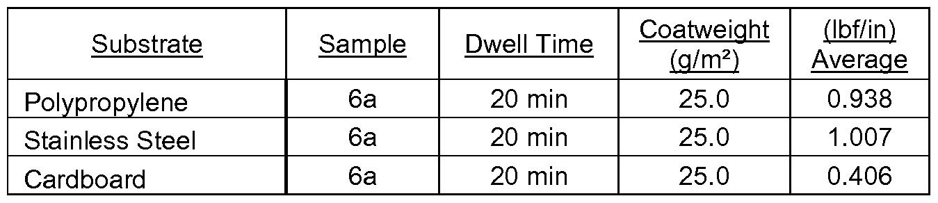


Claims
Priority Applications (15)
| Application Number | Priority Date | Filing Date | Title |
|---|---|---|---|
| BRPI1004349A BRPI1004349A2 (en) | 2009-09-17 | 2010-09-01 | label set and usage |
| RU2011110166/12A RU2552497C2 (en) | 2009-09-17 | 2010-09-01 | Activated adhesives, labels and related methods |
| PL10752960T PL2393897T5 (en) | 2009-09-17 | 2010-09-01 | Activatable adhesive, labels, and related methods |
| US13/119,006 US9200186B2 (en) | 2008-09-17 | 2010-09-01 | Activatable adhesive, labels, and related methods |
| EP10752960.4A EP2393897B8 (en) | 2009-09-17 | 2010-09-01 | Activatable adhesive, labels, and related methods |
| KR1020117006249A KR101879190B1 (en) | 2009-09-17 | 2010-09-01 | Activatable adhesive, labels, and related methods |
| AU2010286191A AU2010286191B2 (en) | 2008-09-17 | 2010-09-01 | Activatable adhesive, labels, and related methods |
| CN201080003211.0A CN102449086B (en) | 2009-09-17 | 2010-09-01 | Activatable adhesive, labels, and related methods |
| ES10752960.4T ES2558439T5 (en) | 2009-09-17 | 2010-09-01 | Activable adhesive, labels and related methods |
| ZA2011/02036A ZA201102036B (en) | 2009-09-17 | 2011-03-17 | Activatable adhesive,labels,and related methods |
| US13/892,498 US9181462B2 (en) | 2008-09-17 | 2013-05-13 | Activatable adhesive, labels, and related methods |
| US13/892,443 US9653006B2 (en) | 2008-09-17 | 2013-05-13 | Activatable adhesive, labels, and related methods |
| US13/892,466 US8927100B2 (en) | 2008-09-17 | 2013-05-13 | Activatable adhesive, labels, and related methods |
| US15/591,364 US10140891B2 (en) | 2008-09-17 | 2017-05-10 | Activatable adhesive, labels, and related methods |
| US16/162,591 US20190051219A1 (en) | 2008-09-17 | 2018-10-17 | Activatable Adhesive, Labels, and Related Methods |
Applications Claiming Priority (2)
| Application Number | Priority Date | Filing Date | Title |
|---|---|---|---|
| US56134909A | 2009-09-17 | 2009-09-17 | |
| US12/561,349 | 2009-09-17 |
Related Parent Applications (1)
| Application Number | Title | Priority Date | Filing Date |
|---|---|---|---|
| US56134909A Continuation-In-Part | 2008-09-17 | 2009-09-17 |
Related Child Applications (5)
| Application Number | Title | Priority Date | Filing Date |
|---|---|---|---|
| US13/119,006 A-371-Of-International US9200186B2 (en) | 2008-09-17 | 2010-09-01 | Activatable adhesive, labels, and related methods |
| US13119066 A-371-Of-International | 2010-09-01 | ||
| US13/892,443 Division US9653006B2 (en) | 2008-09-17 | 2013-05-13 | Activatable adhesive, labels, and related methods |
| US13/892,498 Division US9181462B2 (en) | 2008-09-17 | 2013-05-13 | Activatable adhesive, labels, and related methods |
| US13/892,466 Division US8927100B2 (en) | 2008-09-17 | 2013-05-13 | Activatable adhesive, labels, and related methods |
Publications (2)
| Publication Number | Publication Date |
|---|---|
| WO2011037732A2 true WO2011037732A2 (en) | 2011-03-31 |
| WO2011037732A3 WO2011037732A3 (en) | 2011-09-29 |
Family
ID=43796430
Family Applications (1)
| Application Number | Title | Priority Date | Filing Date |
|---|---|---|---|
| PCT/US2010/047428 WO2011037732A2 (en) | 2008-09-17 | 2010-09-01 | Activatable adhesive, labels, and related methods |
Country Status (11)
| Country | Link |
|---|---|
| US (3) | US9200186B2 (en) |
| EP (1) | EP2393897B8 (en) |
| KR (1) | KR101879190B1 (en) |
| CN (1) | CN102449086B (en) |
| AU (1) | AU2010286191B2 (en) |
| BR (1) | BRPI1004349A2 (en) |
| ES (1) | ES2558439T5 (en) |
| PL (1) | PL2393897T5 (en) |
| RU (1) | RU2552497C2 (en) |
| WO (1) | WO2011037732A2 (en) |
| ZA (1) | ZA201102036B (en) |
Cited By (12)
| Publication number | Priority date | Publication date | Assignee | Title |
|---|---|---|---|---|
| CN102585579A (en) * | 2011-09-29 | 2012-07-18 | 长兴化学工业股份有限公司 | Metal powder oriented resin composition |
| WO2013082101A2 (en) | 2011-11-30 | 2013-06-06 | Avery Dennison Corporation | Activatable linerless labels and activatable adhesives, systems, machines and methods therefor |
| WO2013082095A2 (en) | 2011-11-30 | 2013-06-06 | Avery Dennison Corporation | Linerless labels and activatable adhesives, systems, machines and methods therefor |
| US20140163149A1 (en) * | 2012-12-10 | 2014-06-12 | Avery Dennison Corporation | RF Activatable Adhesives and Applications Thereof |
| WO2014099996A1 (en) * | 2012-12-18 | 2014-06-26 | Imageworks Interactive | Full graphics in-mold label and applications thereof |
| US20150060320A1 (en) * | 2012-03-27 | 2015-03-05 | Upm Raflatac Oy | Labeling of items with wash-off labels |
| WO2016025965A1 (en) * | 2014-08-11 | 2016-02-18 | Henkel IP & Holding GmbH | Optically clear hot melt adhesives and uses thereof |
| US9752022B2 (en) | 2008-07-10 | 2017-09-05 | Avery Dennison Corporation | Composition, film and related methods |
| CN110730980A (en) * | 2017-04-27 | 2020-01-24 | 豪玛股份有限公司 | Activatable adhesive label |
| US10703131B2 (en) | 2010-03-04 | 2020-07-07 | Avery Dennison Corporation | Non-PVC film and non-PVC film laminate |
| US11485162B2 (en) | 2013-12-30 | 2022-11-01 | Avery Dennison Corporation | Polyurethane protective film |
| US11773300B2 (en) | 2017-09-27 | 2023-10-03 | Dow Global Technologies Llc | Acrylic adhesive compositions and methods of making same |
Families Citing this family (17)
| Publication number | Priority date | Publication date | Assignee | Title |
|---|---|---|---|---|
| US20200070074A1 (en) * | 2011-05-25 | 2020-03-05 | Cidra Corporate Services Llc | Polymer coating for selective separation of hydrophobic particles in aqueous slurry |
| JP2013154944A (en) * | 2012-01-31 | 2013-08-15 | Seiko Instruments Inc | Adhesive force development unit, adhesive-label issue device, and printer |
| WO2014116279A1 (en) * | 2013-01-24 | 2014-07-31 | Avery Dennison Corporation | Printer |
| CN104099044A (en) * | 2013-04-02 | 2014-10-15 | 联冠(开平)胶粘制品有限公司 | Label adhesive for sticking on oil stain surface and preparation method thereof |
| AU2014293245B2 (en) * | 2013-07-22 | 2017-02-02 | Pepsico, Inc. | Methods for improving securement of labels to containers |
| US10377117B2 (en) | 2013-09-25 | 2019-08-13 | Avery Dennison Corporation | Tamper evident security labels |
| US9534156B2 (en) | 2014-09-17 | 2017-01-03 | Appvion, Inc. | Linerless record material |
| EP2998235B1 (en) * | 2014-09-18 | 2019-07-24 | Henkel AG & Co. KGaA | Method and device for monitoring a labeling process |
| US20160243653A1 (en) | 2015-02-24 | 2016-08-25 | Electronics For Imaging, Inc. | Compensated laser cutting of labels |
| US9809730B2 (en) * | 2015-06-10 | 2017-11-07 | Upm Raflatac Oy | Printable label comprising a clear face layer and a clear adhesive layer |
| CN105950082A (en) * | 2016-04-01 | 2016-09-21 | 合肥第六元素光电科技有限公司 | Colored pressure-sensitive adhesive, manufacturing method thereof, and manufactured pressure-sensitive adhesive tape |
| CN106742472A (en) * | 2016-11-30 | 2017-05-31 | 芜湖立创包装有限公司 | The labelling machine of drying function |
| US10780715B1 (en) * | 2017-07-20 | 2020-09-22 | Garment Management Systems, LLC | Semi-automatic garment identifier and hanger labeling system |
| CN109013228B (en) * | 2018-08-20 | 2021-04-06 | 湖北万事兴装饰材料有限公司 | Production process of aluminum-plastic panel |
| CN110696436B (en) * | 2019-11-18 | 2021-11-09 | 界首市佳宝包装材料有限公司 | Processing method of durable adhesive label |
| WO2022271595A1 (en) | 2021-06-23 | 2022-12-29 | International Imaging Materials, Inc. | Thermographic imaging element |
| WO2023062544A1 (en) | 2021-10-15 | 2023-04-20 | Avery Dennison Corporation | Heat-activatable linerless label constructions |
Citations (30)
| Publication number | Priority date | Publication date | Assignee | Title |
|---|---|---|---|---|
| US2304787A (en) | 1939-04-12 | 1942-12-15 | Avery Ray Stanton | Nondrying adhesive label and method and apparatus for making same |
| US2569140A (en) | 1946-04-04 | 1951-09-25 | Adhesive Dev Co | Adhesive label and tape dispenser and applicator |
| US2783172A (en) | 1954-09-02 | 1957-02-26 | Avery Adhesive Label Corp | Laminated label structure |
| US3247041A (en) | 1963-05-28 | 1966-04-19 | Union Carbide Corp | Method and apparatus for heat sealing thermoplastic material by radiant energy |
| US3461014A (en) | 1964-06-11 | 1969-08-12 | Albert L James | Magnetic induction method for heat-sealing and bonding predetermined sealing areas |
| US4156626A (en) | 1977-07-18 | 1979-05-29 | Souder James J | Method and apparatus for selectively heating discrete areas of surfaces with radiant energy |
| US4468274A (en) | 1981-07-31 | 1984-08-28 | E.D.M. Corporation | Method and apparatus for bonding thermosensitive adhesive label |
| US4745026A (en) | 1986-03-03 | 1988-05-17 | Mitsubishi Paper Mills, Ltd. | Thermal delayed tack sheets |
| US4784714A (en) | 1986-02-10 | 1988-11-15 | Ricoh Electronics, Inc. | Linerless thermal label printer and applicator |
| US5480502A (en) | 1994-11-21 | 1996-01-02 | Cms Gilbreth Packaging Systems, Inc. | Method and apparatus for applying labels to articles using cooling air on label receiving positions |
| US5569515A (en) | 1994-09-12 | 1996-10-29 | Moore Business Forms, Inc. | Printable linerless label and method for making same |
| US5702771A (en) | 1994-02-22 | 1997-12-30 | Shipston; Adele C. | Activated adhesive system |
| US5749990A (en) | 1994-11-21 | 1998-05-12 | Cms Gillbreth Packaging Systems, Inc. | Method and apparatus for applying labels to articles using bottom feed conveying unit |
| US5895552A (en) | 1994-09-14 | 1999-04-20 | Osaka Sealing Printing Co., Ltd. | Bonding apparatus for cutting label continuum having labels formed successively and bonding label to object |
| US5922169A (en) | 1996-07-27 | 1999-07-13 | Bell & Howell Postal Systems Inc. | Linerless label applying system |
| US5964975A (en) | 1997-08-18 | 1999-10-12 | Trine Labeling Systems, Inc. | Method and apparatus of labeling cylindrical articles with label having formed curl |
| US6006808A (en) | 1998-05-07 | 1999-12-28 | J.I.T. Technologies, Inc. | Label tamp |
| US6031553A (en) | 1996-10-18 | 2000-02-29 | Ricoh Company, Ltd. | Heat activation method for thermosensitive adhesive label, and heat activation apparatus and label printer for the same |
| US6043190A (en) | 1997-07-23 | 2000-03-28 | Ricoh Company, Ltd. | Thermosensitive recording label |
| US6388692B1 (en) | 1996-10-18 | 2002-05-14 | Ricoh Company, Ltd. | Heat activation method for thermosensitive adhesive label, and heat activation apparatus and label printer for the same |
| US6471802B1 (en) | 1998-12-07 | 2002-10-29 | Gerro Plast Gmbh | Labeling apparatus and method |
| US6500536B1 (en) | 1999-09-14 | 2002-12-31 | Ricoh Company, Ltd. | Heat activatable adhesive composition and adhesive sheet having adhesive layer thereof |
| US6501495B1 (en) | 1929-04-22 | 2002-12-31 | Ricoh Company, Ltd. | Heat activating and thermosensitive recording for thermosensitive adhesive label |
| US20030041963A1 (en) | 2001-08-20 | 2003-03-06 | Lie-Zhong Gong | Reactivatable adhesives |
| US6767102B1 (en) | 1996-05-30 | 2004-07-27 | Avery Dennison Corporation | Retroreflective articles having microcubes, and tools and methods for forming microcubes |
| US20040166309A1 (en) | 2003-02-22 | 2004-08-26 | Lie-Zhong Gong | Reactivatable adhesive |
| US6803100B1 (en) | 1999-01-19 | 2004-10-12 | Celanese Emulsions Gmbh | Rewettable adhesive systems |
| US6899155B2 (en) | 2000-04-10 | 2005-05-31 | Siemens Aktiengesellschaft | Device for applying self-adhesive, substrate-free labels to flat articles |
| US7026047B2 (en) | 2001-04-05 | 2006-04-11 | Ovd Kinegram Ag | Security film system with reactive adhesives |
| US7029549B1 (en) | 1999-09-28 | 2006-04-18 | Lts Lohmann Therapie-Systeme Ag | Method and device for dispensing adhesive laminate segments |
Family Cites Families (174)
| Publication number | Priority date | Publication date | Assignee | Title |
|---|---|---|---|---|
| US2524945A (en) | 1945-04-25 | 1950-10-10 | New Jersey Machine Corp | Machine and method for applying labels to articles on a conveyer |
| US2525471A (en) | 1947-06-25 | 1950-10-10 | Abram P Balzer | Coupler |
| US2676726A (en) | 1950-12-21 | 1954-04-27 | New Jersey Machine Corp | Method of applying labels to articles |
| GB1102244A (en) | 1964-04-06 | 1968-02-07 | Paper Manuf Co | Adhesive product |
| US3803100A (en) | 1966-12-29 | 1974-04-09 | Sumitomo Electric Industries | Method for preparing soluble polyamideimides |
| US4135033A (en) | 1977-02-16 | 1979-01-16 | Lawton William R | Heat-activated adhesive coating |
| JPS56106984U (en) | 1980-01-18 | 1981-08-20 | ||
| US4248748A (en) | 1980-02-04 | 1981-02-03 | Minnesota Mining And Manufacturing Company | Heat-activated adhesive |
| US4280942A (en) | 1980-07-09 | 1981-07-28 | Formica Corporation | Aqueous acrylic contact adhesive |
| DE3270513D1 (en) | 1981-12-28 | 1986-05-15 | Minnesota Mining & Mfg | Hot-tackifying adhesive tape |
| US4880683A (en) | 1981-12-28 | 1989-11-14 | Minnesota Mining And Manufacturing Company | Hot-tackifying adhesive tape |
| US4427744A (en) * | 1982-08-19 | 1984-01-24 | H. B. Fuller Company | Heat-activated pressure sensitive adhesive for bonding label stock to plastic film, metal foil and the like |
| US4522870A (en) | 1982-11-04 | 1985-06-11 | Minnesota Mining And Manufacturing Company | Linerless double-coated pressure-sensitive adhesive tape |
| US4590497A (en) | 1984-11-05 | 1986-05-20 | Ricoh Electronics, Inc. | Heat insulated thermosensitive paper |
| JPS62152821A (en) | 1985-12-27 | 1987-07-07 | Sekisui Chem Co Ltd | Manufacture of fiber reinforced resin molded product |
| US4707211A (en) | 1986-02-10 | 1987-11-17 | Ricoh Electronics, Inc. | Linerless thermal label printer and applicator |
| JPH0431481Y2 (en) | 1986-03-07 | 1992-07-29 | ||
| US4923919A (en) | 1986-08-22 | 1990-05-08 | S. C. Johnson & Son, Inc. | Pressure sensitive adhesive compositions |
| US5252393A (en) | 1987-06-25 | 1993-10-12 | Mitsubishi Paper Mills Ltd. | Thermal delayed-tack adhesive compositions and thermal delayed-tack adhesive sheets |
| JPH0792912B2 (en) | 1987-10-19 | 1995-10-09 | コニカ株式会社 | Magnetic recording medium |
| JPH0617018Y2 (en) | 1988-12-19 | 1994-05-02 | オーバル機器工業株式会社 | Elastic tube feeder in elastic tube pump |
| JPH0617018B2 (en) | 1989-07-20 | 1994-03-09 | 住友ゴム工業株式会社 | Tire forming vulcanization mold |
| US5240755A (en) | 1991-04-23 | 1993-08-31 | Zimmer Industries, Inc. | Perforated label web and method of producing such web |
| US5478807A (en) | 1991-08-19 | 1995-12-26 | Genentech, Inc. | Use of relaxin in the treatment of bradycardia |
| TW221061B (en) * | 1991-12-31 | 1994-02-11 | Minnesota Mining & Mfg | |
| US5674345A (en) | 1992-07-01 | 1997-10-07 | Moore Business Forms, Inc. | Linerless label printer applicator |
| ES2148238T3 (en) | 1992-08-06 | 2000-10-16 | Dow Chemical Co | PRESSURE SENSITIVE ADHESIVE LATEX COMPOSITIONS. |
| US5421933A (en) * | 1992-12-23 | 1995-06-06 | Graydon Wesley Nedblake | System for producing labels from a web |
| US5326644A (en) | 1993-02-05 | 1994-07-05 | Avery Dennison Corporation | Repulpable pressure-sensitive adhesive compositions |
| JP2875715B2 (en) | 1993-03-05 | 1999-03-31 | 凸版印刷株式会社 | Heat-sensitive adhesive label and method of peeling heat-sensitive adhesive label |
| CA2124021A1 (en) | 1993-05-21 | 1994-11-22 | John Samonides Sr. | Adhesive for labels and the like |
| US5464692A (en) | 1993-06-17 | 1995-11-07 | Quality Manufacturing Incorporated | Flexible masking tape |
| JPH07145352A (en) | 1993-11-24 | 1995-06-06 | Nippon Synthetic Chem Ind Co Ltd:The | Pressure-sensitive adhesive tape its production |
| ATE167427T1 (en) | 1994-09-16 | 1998-07-15 | Avery Dennison Corp | MULTI-LAYER ADHESIVE STRUCTURE WITH BARRIER LAYER |
| SI9400362A (en) | 1994-09-19 | 1996-04-30 | Aero | Procedure for the preparation of the carriers that are impregnated or coated with microcapsulated aromatic substances |
| US5588239A (en) | 1995-02-13 | 1996-12-31 | Ccl Label, Inc. | Expanded content label adapted for application to curved surfaces |
| US6053231A (en) | 1995-03-23 | 2000-04-25 | Osaka Sealing Printing Co., Ltd. | Bonding apparatus for cutting label continuum having labels formed thereon and bonding label to object |
| US5725719A (en) | 1995-06-26 | 1998-03-10 | Wallace Computer Services, Inc. | Linerless label product, method of making, apparatus and method for dispensing the product |
| JP3103832B2 (en) | 1995-09-25 | 2000-10-30 | 東洋インキ製造株式会社 | Delayed tack adhesive composition |
| JPH10147753A (en) | 1996-01-30 | 1998-06-02 | Ricoh Co Ltd | Method and apparatus for thermally activating heat-sensitive tacky adhesive label |
| US5768991A (en) | 1996-04-10 | 1998-06-23 | Zebra Technologies Corporation | Label printer for printing moistened adhesive bar code labels |
| US5897722A (en) | 1996-07-12 | 1999-04-27 | B & H Manufacturing Company, Inc. | Process for applying labels with delayed adhesive activation |
| JPH10258477A (en) | 1996-09-13 | 1998-09-29 | Ricoh Co Ltd | Heat sensitive tacky adhesive label |
| EP0929399B1 (en) | 1996-09-27 | 2005-07-20 | Avery Dennison Corporation | Prelaminate pressure-sensitive adhesive constructions |
| US20020025430A1 (en) | 1996-12-23 | 2002-02-28 | Rudolf Weissgerber | Compsite paper material with a pressure-sensitive adhesive coating finished to be resistant to repulping |
| CA2278656C (en) | 1997-01-28 | 2009-09-08 | Stepan Company | Improved emulsion polymerization process utilizing ethylenically unsaturated amine salts of sulfonic, phosphoric and carboxylic acids |
| US5827913A (en) | 1997-02-05 | 1998-10-27 | H.B. Fuller Licensing & Financing, Inc. | Hot melt adhesive comprising an encapsulated ingredient |
| US5895801A (en) | 1997-03-31 | 1999-04-20 | Avery Dennison Corporation | Pressure-sensitive adhesives for marking films |
| US6124032A (en) | 1998-01-15 | 2000-09-26 | Bloch; Gilbert | Pressure sensitive heat activated filmic adhesive tape |
| US6024822A (en) | 1998-02-09 | 2000-02-15 | Ato Findley, Inc. | Method of making disposable nonwoven articles with microwave activatable hot melt adhesive |
| US6348679B1 (en) * | 1998-03-17 | 2002-02-19 | Ameritherm, Inc. | RF active compositions for use in adhesion, bonding and coating |
| US6191382B1 (en) | 1998-04-02 | 2001-02-20 | Avery Dennison Corporation | Dynamic laser cutting apparatus |
| US6461706B1 (en) * | 1998-04-17 | 2002-10-08 | Avery Dennison Corporation | Multilayer films and labels |
| US6103316A (en) * | 1998-07-17 | 2000-08-15 | 3M Innovative Properties Company | Method of making electron beam polymerized emulsion-based acrylate pressure sensitive adhesives |
| US6206071B1 (en) | 1998-08-05 | 2001-03-27 | Advanced Label Systems, Inc. | Apparatus and method for applying linerless labels |
| US6294038B1 (en) | 1998-08-05 | 2001-09-25 | Advanced Label Systems, Inc. | Apparatus and method for applying linerless labels |
| US20030129431A1 (en) | 1998-10-23 | 2003-07-10 | Michael R. Nowak | Composite wrap material |
| US6586510B1 (en) | 1998-12-15 | 2003-07-01 | Avery Dennison Corporation | Removable emulsion pressure-sensitive adhesives |
| EP1170313B1 (en) | 1998-12-22 | 2010-06-02 | Denki Kagaku Kogyo Kabushiki Kaisha | Cross-copolymerized olefin/styrene/diene copolymer, process for the production of the same and uses thereof |
| US6734256B1 (en) | 1998-12-29 | 2004-05-11 | 3M Innovative Properties Company | Block copolymer hot-melt processable adhesives, methods of their preparation, and articles therefrom |
| DE69833800T3 (en) | 1998-12-29 | 2013-08-22 | Minnesota Mining And Mfg. Co. | MELT ADHESIVES FROM BLOCK COPOLYMERS, METHOD FOR THEIR PRODUCTION AND OBJECTS THEREFOR |
| EP1163308B1 (en) | 1999-03-19 | 2004-10-06 | Minnesota Mining And Manufacturing Company | Plasticized pressure sensitive adhesive |
| US6624273B1 (en) * | 1999-03-19 | 2003-09-23 | 3M Innovative Properties Company | Plasticized acrylics for pressure sensitive adhesive applications |
| US6139932A (en) | 1999-04-09 | 2000-10-31 | Monarch Marking Systems, Inc. | Linerless label web roll |
| CA2304944A1 (en) | 1999-04-12 | 2000-10-12 | Grand Rapids Label Company | Label printer/applicator with improved label cutting, control and application and method for doing the same |
| US6401787B1 (en) | 1999-04-22 | 2002-06-11 | Sansei Seiki Co., Ltd. | Single drum type thermo sensitive glue labeler |
| US6893717B1 (en) | 1999-07-08 | 2005-05-17 | Kuolih Tsai | Heat-transfer label including non-wax release coating |
| US6368449B1 (en) | 1999-11-01 | 2002-04-09 | Linear Products Inc. | Heated wheel for application of heat-activated precoated adhesive tape or string |
| US6525129B1 (en) | 1999-12-20 | 2003-02-25 | Avery Dennison Corporation | Water-soluble pressure-sensitive adhesives |
| DE10007692A1 (en) | 2000-02-19 | 2001-08-23 | Basf Ag | Pressure sensitive adhesives |
| US7239592B2 (en) | 2000-04-03 | 2007-07-03 | Stmicroelectronics S.A. | Method for indicating a sector on a data medium and data medium suited to this method |
| WO2001085866A2 (en) | 2000-05-05 | 2001-11-15 | National Starch And Chemical Investment Holding Corporation | Aqueous adhesive formulations |
| US6551439B1 (en) * | 2000-06-06 | 2003-04-22 | Applied Extrusion Technologies, Inc. | Ultraviolet labeling apparatus and method |
| US6592990B2 (en) | 2000-09-06 | 2003-07-15 | Appleton Papers Inc. | In situ microencapsulated adhesive |
| US6828017B2 (en) | 2000-09-29 | 2004-12-07 | Ricoh Company, Ltd. | Heat-sensitive adhesive material, method of preparing same and method of using same |
| ATE312147T1 (en) | 2000-10-25 | 2005-12-15 | 3M Innovative Properties Co | METHOD OF USING LATENT, OVER-TACKIFIED ADHESIVES |
| US6686033B1 (en) | 2000-12-27 | 2004-02-03 | H.B. Fuller Licensing & Financing Inc. | Waterborne composition exhibiting sound damping property at low and high frequencies |
| US6830645B2 (en) | 2001-03-26 | 2004-12-14 | Appleton Papers Inc. | System and method for rupturing encapsulated adhesive in sheet media |
| US20020168212A1 (en) * | 2001-05-09 | 2002-11-14 | Nedblake Greydon W. | On-demand label applicator system |
| WO2003031488A1 (en) | 2001-10-05 | 2003-04-17 | Avery Dennison Corporation | High solids content, low-viscosity emulsion polymers |
| US6773653B2 (en) * | 2001-10-05 | 2004-08-10 | Avery Dennison Corporation | In-mold labeling method |
| US20030089452A1 (en) | 2001-11-15 | 2003-05-15 | Advanced Label Systems, Inc. | Apparatus and method for applying linerless labels |
| US7815761B2 (en) | 2001-11-15 | 2010-10-19 | Advanced Label Systems, Inc. | Apparatus and method for applying labels |
| FI113807B (en) | 2001-12-07 | 2004-06-15 | Stora Enso Oyj | Digital printing method and paper or paperboard suitable for this |
| US6936131B2 (en) | 2002-01-31 | 2005-08-30 | 3M Innovative Properties Company | Encapsulation of organic electronic devices using adsorbent loaded adhesives |
| JP4219132B2 (en) | 2002-04-19 | 2009-02-04 | セイコーインスツル株式会社 | Thermal activation apparatus for heat-sensitive adhesive sheet and printer apparatus using the thermal activation apparatus |
| JP2003316266A (en) | 2002-04-22 | 2003-11-07 | Sii P & S Inc | Thermal activation apparatus of heat-sensitive adhesive sheet and printer apparatus |
| US6824868B2 (en) * | 2002-04-30 | 2004-11-30 | Solutia, Inc. | Digital color-design composite for use in laminated glass |
| BR0304878A (en) | 2002-05-22 | 2004-08-03 | Honda Giken Kogyo Kabashiki Ka | Label, a method of use thereof and a method and apparatus for affixing the label |
| JP4177601B2 (en) | 2002-06-05 | 2008-11-05 | セイコーインスツル株式会社 | Thermal activation apparatus and printer apparatus for heat-sensitive adhesive sheet |
| JP3955240B2 (en) | 2002-06-21 | 2007-08-08 | 王子製紙株式会社 | Acrylic emulsion type adhesive and adhesive sheet |
| GB0215374D0 (en) | 2002-07-03 | 2002-08-14 | Wade Richard | Applying adhesive labels to products and product containers |
| US6905269B2 (en) | 2002-07-03 | 2005-06-14 | Oki Data Americas, Inc. | System and method for continuous label printing |
| US20060100299A1 (en) | 2002-07-24 | 2006-05-11 | Ranjit Malik | Transformable pressure sensitive adhesive tape and use thereof in display screens |
| DE10243704A1 (en) * | 2002-09-20 | 2004-03-25 | Khs Maschinen- Und Anlagenbau Ag | Labeling machine for processing single-sheet labels coated with thermally activated glue |
| JP4137569B2 (en) * | 2002-09-25 | 2008-08-20 | セイコーインスツル株式会社 | Printer for heat-sensitive adhesive sheet |
| US8653169B2 (en) * | 2002-10-15 | 2014-02-18 | Exxonmobil Chemical Patents Inc. | Propylene copolymers for adhesive applications |
| US6916130B1 (en) | 2002-11-06 | 2005-07-12 | Brady Worldwide, Inc. | Method of printing, activating and issuing an activated time dependent label |
| US6806320B2 (en) | 2002-11-15 | 2004-10-19 | 3M Innovative Properties Company | Block copolymer melt-processable compositions, methods of their preparation, and articles therefrom |
| US7021214B2 (en) | 2003-01-27 | 2006-04-04 | Ricoh Company, Ltd. | Method for issuing label with thermosensitive adhesive |
| ATE356032T1 (en) | 2003-02-06 | 2007-03-15 | Irplast Spa | LABELING MACHINE |
| US20040163754A1 (en) | 2003-02-22 | 2004-08-26 | Nowicki James W. | Reactivation of pre-applied adhesives by ultrasonic waves |
| US20050139323A1 (en) | 2003-04-11 | 2005-06-30 | Syde Gary V. | Linerless label application assembly |
| US7121311B2 (en) | 2003-04-11 | 2006-10-17 | Bowe Bell + Howell Postal Systems Company | Linerless label application assembly |
| US20040219379A1 (en) | 2003-04-30 | 2004-11-04 | Oji Paper Co., Ltd. | Electrophotographic recording sheet |
| JP4434665B2 (en) | 2003-05-19 | 2010-03-17 | 株式会社リコー | Thermally active adhesive and thermally active adhesive sheet |
| EP1479743B1 (en) | 2003-05-23 | 2007-07-18 | Ricoh Company, Ltd. | Heat-sensitive adhesive material, adhered article, process and apparatus for thermally activating the heat-sensitive adhesive material |
| US20040265504A1 (en) | 2003-06-27 | 2004-12-30 | Christophe Magnin | Non-metalic substrate having an electostatically applied activatable powder adhesive |
| US7141285B2 (en) | 2003-10-15 | 2006-11-28 | Avery Dennison Corporation | Composite construction containing barrier layer |
| US7691437B2 (en) * | 2003-10-31 | 2010-04-06 | 3M Innovative Properties Company | Method for preparing a pressure-sensitive adhesive |
| WO2005070663A1 (en) | 2004-01-08 | 2005-08-04 | Avery Dennison Corporation | Multi-layer composites and sheet labels |
| EA011898B1 (en) | 2004-03-09 | 2009-06-30 | Спир Груп Холдингз Лимитед | Label for glass containers and method for removing thereof |
| US7051944B2 (en) | 2004-04-20 | 2006-05-30 | Premark Feg L.L.C. | Scale and related printing apparatus and method for producing promotion offer labels using label stock with heat activated adhesive |
| US7470736B2 (en) | 2004-05-03 | 2008-12-30 | Michelman, Inc. | Primer coating for enhancing adhesion of liquid toner to polymeric substrates |
| US20050276938A1 (en) | 2004-05-25 | 2005-12-15 | Mccormick Demetrius T | Adhesive for bag sealing application |
| US20050266194A1 (en) | 2004-05-29 | 2005-12-01 | Peters Daniel F | Peelable laminate and process of making the same |
| US7232273B2 (en) | 2004-07-30 | 2007-06-19 | The Boeing Company | Method and apparatus for applying sealant to fasteners |
| JP2006052279A (en) | 2004-08-11 | 2006-02-23 | Tokai Carbon Co Ltd | Carbon black colorant for semiconductor sealing material and method for producing the same |
| US7102658B2 (en) * | 2004-10-14 | 2006-09-05 | Seiko Instruments Inc. | Printing and thermal activation method and device for a heat-sensitive adhesive sheet |
| US7478956B2 (en) | 2004-10-14 | 2009-01-20 | Seiko Instruments Inc. | Printer for printing on both a heat-sensitive adhesive label and an ordinary label |
| US7101100B2 (en) | 2004-10-14 | 2006-09-05 | Seiko Instruments Inc. | Printer apparatus |
| JP4708007B2 (en) | 2004-12-02 | 2011-06-22 | 株式会社フジシールインターナショナル | Shrink labels and labeled containers |
| JP4518323B2 (en) | 2005-01-05 | 2010-08-04 | セイコーインスツル株式会社 | Thermal activation device, printer, thermal activation method, and adhesive label manufacturing method |
| MX2007008258A (en) | 2005-01-10 | 2007-08-22 | Avery Dennison Corp | Removable curl labels. |
| GB0501369D0 (en) | 2005-01-22 | 2005-03-02 | Stepping Stones Invest Ltd | Improvements to labels and application apparatus therefor |
| JP4679165B2 (en) * | 2005-01-25 | 2011-04-27 | コクヨS&T株式会社 | Adhesive products and transfer tools |
| JP4750442B2 (en) | 2005-03-23 | 2011-08-17 | リンテック株式会社 | Label laminate |
| US7902282B2 (en) | 2005-04-28 | 2011-03-08 | Api Corporation | Pressure-sensitive adhesive containing near infrared absorbing coloring matter |
| JP5021183B2 (en) | 2005-05-20 | 2012-09-05 | アークレイ株式会社 | Protein immobilization membrane, immobilization method, and biosensor |
| CN101180376B (en) * | 2005-05-20 | 2012-11-28 | 艾利丹尼森公司 | Water whitening-resistant pressure sensitive adhesives |
| DE102005051471A1 (en) | 2005-10-21 | 2007-05-16 | Bizerba Gmbh & Co Kg | Device for the provision of activated indicators for product labeling, product labeling and methods for providing indicators for the labeling of goods |
| US7833369B2 (en) | 2005-12-14 | 2010-11-16 | Kimberly-Clark Worldwide, Inc. | Strand, substrate, and/or composite comprising re-activatable adhesive composition, and processes for making and/or utilizing same |
| WO2007136767A2 (en) | 2006-05-18 | 2007-11-29 | Max International Converters, Inc. | Thermally printable adhesive label |
| US20100273017A1 (en) | 2006-06-29 | 2010-10-28 | Files John C | Hybrid Packaging Material |
| RU2461597C2 (en) | 2006-11-02 | 2012-09-20 | Эйвери Деннисон Корпорейшн | Emulsion adhesive for washable film |
| WO2008075652A1 (en) | 2006-12-20 | 2008-06-26 | Kabushiki Kaisha Sato | Thermally active label, and printer for the thermally active label |
| KR20100017670A (en) | 2007-05-18 | 2010-02-16 | 쓰리엠 이노베이티브 프로퍼티즈 컴파니 | Tamper indicating article |
| GB2449647B (en) | 2007-05-29 | 2010-01-13 | Fortium Technologies Ltd | Optical discs |
| WO2008157611A2 (en) | 2007-06-18 | 2008-12-24 | 3M Innovative Properties Company | Colored acrylic adhesive and marking film |
| US20090047514A1 (en) | 2007-08-15 | 2009-02-19 | Allen David P | Thermal Activated Pressure Sensitive Adhesive and Method for Producing the Same and Product therewith |
| US9175192B2 (en) | 2007-09-06 | 2015-11-03 | Upm Raflatac Oy | Method for manufacturing a label laminate |
| CN101396883B (en) | 2007-09-24 | 2012-10-17 | 3M创新有限公司 | Label capable of being labeled using laser without contact, production method and labeling method |
| WO2009041920A1 (en) | 2007-09-27 | 2009-04-02 | Aero, Kemicna, Graficna In Papirna Industrija, D.D. Celje | Microsphere acrylic copolymer adhesives and process of manufacturing thereof |
| US10399313B2 (en) | 2007-11-13 | 2019-09-03 | Invista North America S.A R.L. | Bonding of heat-activated films including a plasticizer |
| WO2009071499A1 (en) | 2007-12-05 | 2009-06-11 | Basf Se | Microcapsules having radiation-induced release |
| EP2222810A1 (en) | 2007-12-18 | 2010-09-01 | UPM Raflatac Oy | Label, a method in labelling and use of an adhesive |
| US20090165942A1 (en) | 2007-12-26 | 2009-07-02 | National Starch And Chemical Investment Holding Corporation | Insulation and Method of Installing |
| US8764323B2 (en) | 2007-12-31 | 2014-07-01 | Ncr Corporation | Heat-activated linerless label |
| WO2009095534A1 (en) | 2008-01-28 | 2009-08-06 | Upm Raflatac Oy | A label and a method for attaching the label to an item |
| WO2009114588A1 (en) | 2008-03-12 | 2009-09-17 | Nanopaper, Llc | Grease-resistant films and coatings |
| CN201258438Y (en) | 2008-08-11 | 2009-06-17 | 杭州广联复合材料有限公司 | Sticker body paper |
| CN201263232Y (en) | 2008-08-26 | 2009-06-24 | 鲁永忠 | External connection centralized control constant-current driving unit and monitoring system for LED lighting lamp |
| CN201270114Y (en) | 2008-10-21 | 2009-07-08 | 侯海坡 | Signboard |
| US8777271B2 (en) | 2008-12-18 | 2014-07-15 | Premier Print & Services Group, Inc. | Linerless packing and shipping label system |
| CN201336109Y (en) | 2008-12-26 | 2009-10-28 | 上海寺冈电子有限公司 | Bottomless label paper |
| JP5382851B2 (en) | 2009-01-21 | 2014-01-08 | セイコーインスツル株式会社 | Adhesive label manufacturing apparatus and adhesive label manufacturing method |
| CN201406398Y (en) | 2009-03-27 | 2010-02-17 | 深圳市摩码科技有限公司 | Silicone oil-free and dust-free self-adhesive structure |
| JP5604687B2 (en) | 2009-03-30 | 2014-10-15 | 株式会社フジシール | Shrink label |
| CN201662968U (en) | 2009-05-19 | 2010-12-01 | 黄欣 | Luminous tag |
| JP5578835B2 (en) | 2009-11-16 | 2014-08-27 | 日東電工株式会社 | Adhesive tape |
| CN201788649U (en) | 2009-11-23 | 2011-04-06 | 赵越 | Clothing trademark body |
| US8537184B2 (en) | 2010-02-25 | 2013-09-17 | Ncr Corporation | Linerless labels |
| CN201751926U (en) | 2010-04-29 | 2011-02-23 | 东莞市冠宏包装实业有限公司 | Color advertising adhesive tape |
| CN201804499U (en) | 2010-04-30 | 2011-04-20 | 淄博泰宝防伪技术产品有限公司 | Color filtration type anti-counterfeit label |
| CN201725497U (en) | 2010-04-30 | 2011-01-26 | 淄博泰宝防伪技术产品有限公司 | Fringe shielding anti-counterfeit mark |
| CN201689603U (en) | 2010-06-03 | 2010-12-29 | 黎世东 | Traveling case label |
| CN201927278U (en) | 2010-10-13 | 2011-08-10 | 鲍卫昌 | Novel English label |
| CN201998495U (en) | 2010-12-01 | 2011-10-05 | 中山国安火炬科技发展有限公司 | Anti-jumping label |
| CN102097034A (en) | 2010-12-01 | 2011-06-15 | 中山国安火炬科技发展有限公司 | Label jumping resistance label |
| CN202084247U (en) | 2011-05-18 | 2011-12-21 | 江阴宝柏包装有限公司 | Annular label |
| CN202071775U (en) | 2011-05-23 | 2011-12-14 | 岳黎明 | Burglarproof label sticker for automobile |
| CN202163232U (en) | 2011-06-07 | 2012-03-14 | 陈�胜 | Paper-cut based on static membrane |
| US20130133532A1 (en) | 2011-11-30 | 2013-05-30 | Avery Dennison Corporation | Linerless labels and activatable adhesives, systems, machines and methods therefor |
| US20130133824A1 (en) | 2011-11-30 | 2013-05-30 | Avery Dennison Corporation | Activatable Linerless Labels and Activatable Adhesives, Systems, Machines and Methods Therefor |
-
2010
- 2010-09-01 RU RU2011110166/12A patent/RU2552497C2/en not_active IP Right Cessation
- 2010-09-01 EP EP10752960.4A patent/EP2393897B8/en not_active Not-in-force
- 2010-09-01 CN CN201080003211.0A patent/CN102449086B/en not_active Expired - Fee Related
- 2010-09-01 AU AU2010286191A patent/AU2010286191B2/en not_active Ceased
- 2010-09-01 WO PCT/US2010/047428 patent/WO2011037732A2/en active Application Filing
- 2010-09-01 ES ES10752960.4T patent/ES2558439T5/en active Active
- 2010-09-01 BR BRPI1004349A patent/BRPI1004349A2/en not_active Application Discontinuation
- 2010-09-01 PL PL10752960T patent/PL2393897T5/en unknown
- 2010-09-01 KR KR1020117006249A patent/KR101879190B1/en active IP Right Grant
- 2010-09-01 US US13/119,006 patent/US9200186B2/en not_active Expired - Fee Related
-
2011
- 2011-03-17 ZA ZA2011/02036A patent/ZA201102036B/en unknown
-
2013
- 2013-05-13 US US13/892,498 patent/US9181462B2/en not_active Expired - Fee Related
- 2013-05-13 US US13/892,466 patent/US8927100B2/en not_active Expired - Fee Related
Patent Citations (32)
| Publication number | Priority date | Publication date | Assignee | Title |
|---|---|---|---|---|
| US6501495B1 (en) | 1929-04-22 | 2002-12-31 | Ricoh Company, Ltd. | Heat activating and thermosensitive recording for thermosensitive adhesive label |
| US2304787A (en) | 1939-04-12 | 1942-12-15 | Avery Ray Stanton | Nondrying adhesive label and method and apparatus for making same |
| US2569140A (en) | 1946-04-04 | 1951-09-25 | Adhesive Dev Co | Adhesive label and tape dispenser and applicator |
| US2783172A (en) | 1954-09-02 | 1957-02-26 | Avery Adhesive Label Corp | Laminated label structure |
| US3247041A (en) | 1963-05-28 | 1966-04-19 | Union Carbide Corp | Method and apparatus for heat sealing thermoplastic material by radiant energy |
| US3461014A (en) | 1964-06-11 | 1969-08-12 | Albert L James | Magnetic induction method for heat-sealing and bonding predetermined sealing areas |
| US4156626A (en) | 1977-07-18 | 1979-05-29 | Souder James J | Method and apparatus for selectively heating discrete areas of surfaces with radiant energy |
| US4468274A (en) | 1981-07-31 | 1984-08-28 | E.D.M. Corporation | Method and apparatus for bonding thermosensitive adhesive label |
| US4784714A (en) | 1986-02-10 | 1988-11-15 | Ricoh Electronics, Inc. | Linerless thermal label printer and applicator |
| US4745026A (en) | 1986-03-03 | 1988-05-17 | Mitsubishi Paper Mills, Ltd. | Thermal delayed tack sheets |
| US6326450B1 (en) | 1994-02-22 | 2001-12-04 | Moore Business Forms | Activated adhesive system |
| US6492019B1 (en) | 1994-02-22 | 2002-12-10 | Moore Business Forms | Activated adhesive system |
| US5702771A (en) | 1994-02-22 | 1997-12-30 | Shipston; Adele C. | Activated adhesive system |
| US5569515A (en) | 1994-09-12 | 1996-10-29 | Moore Business Forms, Inc. | Printable linerless label and method for making same |
| US5895552A (en) | 1994-09-14 | 1999-04-20 | Osaka Sealing Printing Co., Ltd. | Bonding apparatus for cutting label continuum having labels formed successively and bonding label to object |
| US5749990A (en) | 1994-11-21 | 1998-05-12 | Cms Gillbreth Packaging Systems, Inc. | Method and apparatus for applying labels to articles using bottom feed conveying unit |
| US5480502A (en) | 1994-11-21 | 1996-01-02 | Cms Gilbreth Packaging Systems, Inc. | Method and apparatus for applying labels to articles using cooling air on label receiving positions |
| US6767102B1 (en) | 1996-05-30 | 2004-07-27 | Avery Dennison Corporation | Retroreflective articles having microcubes, and tools and methods for forming microcubes |
| US5922169A (en) | 1996-07-27 | 1999-07-13 | Bell & Howell Postal Systems Inc. | Linerless label applying system |
| US6388692B1 (en) | 1996-10-18 | 2002-05-14 | Ricoh Company, Ltd. | Heat activation method for thermosensitive adhesive label, and heat activation apparatus and label printer for the same |
| US6031553A (en) | 1996-10-18 | 2000-02-29 | Ricoh Company, Ltd. | Heat activation method for thermosensitive adhesive label, and heat activation apparatus and label printer for the same |
| US6043190A (en) | 1997-07-23 | 2000-03-28 | Ricoh Company, Ltd. | Thermosensitive recording label |
| US5964975A (en) | 1997-08-18 | 1999-10-12 | Trine Labeling Systems, Inc. | Method and apparatus of labeling cylindrical articles with label having formed curl |
| US6006808A (en) | 1998-05-07 | 1999-12-28 | J.I.T. Technologies, Inc. | Label tamp |
| US6471802B1 (en) | 1998-12-07 | 2002-10-29 | Gerro Plast Gmbh | Labeling apparatus and method |
| US6803100B1 (en) | 1999-01-19 | 2004-10-12 | Celanese Emulsions Gmbh | Rewettable adhesive systems |
| US6500536B1 (en) | 1999-09-14 | 2002-12-31 | Ricoh Company, Ltd. | Heat activatable adhesive composition and adhesive sheet having adhesive layer thereof |
| US7029549B1 (en) | 1999-09-28 | 2006-04-18 | Lts Lohmann Therapie-Systeme Ag | Method and device for dispensing adhesive laminate segments |
| US6899155B2 (en) | 2000-04-10 | 2005-05-31 | Siemens Aktiengesellschaft | Device for applying self-adhesive, substrate-free labels to flat articles |
| US7026047B2 (en) | 2001-04-05 | 2006-04-11 | Ovd Kinegram Ag | Security film system with reactive adhesives |
| US20030041963A1 (en) | 2001-08-20 | 2003-03-06 | Lie-Zhong Gong | Reactivatable adhesives |
| US20040166309A1 (en) | 2003-02-22 | 2004-08-26 | Lie-Zhong Gong | Reactivatable adhesive |
Non-Patent Citations (2)
| Title |
|---|
| CHUANG HK; CHIU C.; PANIAGUA R.: "Avery Adhesive Test yields more performance data than traditional probe", ADHESIVES AGE, 1997, pages 18 - 23, XP002903167 |
| D. SATAS,: "Handbook of Pressure Sensitive Adhesive Technology(2d Edition),", 1989, pages: 172 - 176 |
Cited By (28)
| Publication number | Priority date | Publication date | Assignee | Title |
|---|---|---|---|---|
| US9752022B2 (en) | 2008-07-10 | 2017-09-05 | Avery Dennison Corporation | Composition, film and related methods |
| US10703131B2 (en) | 2010-03-04 | 2020-07-07 | Avery Dennison Corporation | Non-PVC film and non-PVC film laminate |
| CN102585579A (en) * | 2011-09-29 | 2012-07-18 | 长兴化学工业股份有限公司 | Metal powder oriented resin composition |
| CN102585579B (en) * | 2011-09-29 | 2015-02-11 | 长兴化学工业股份有限公司 | metal powder oriented resin composition |
| WO2013082101A3 (en) * | 2011-11-30 | 2013-11-07 | Avery Dennison Corporation | Activatable linerless labels and activatable adhesives, systems, machines and methods therefor |
| CN104093636B (en) * | 2011-11-30 | 2017-07-28 | 艾利丹尼森公司 | Linerless label and its adhesive, system, machine and method can be activated |
| RU2666483C2 (en) * | 2011-11-30 | 2018-09-07 | Эйвери Деннисон Корпорейшн | Activatable linerless labels and activatable adhesive, system, device and methods for application thereof |
| EP3404644A1 (en) | 2011-11-30 | 2018-11-21 | Avery Dennison Corporation | Linerless labels and activatable adhesives, systems, machines and methods therefor |
| CN104080705A (en) * | 2011-11-30 | 2014-10-01 | 艾利丹尼森公司 | Activatable linerless labels and activatable adhesives, systems, machines and methods therefor |
| CN104093636A (en) * | 2011-11-30 | 2014-10-08 | 艾利丹尼森公司 | Linerless labels and activatable adhesives, systems, machines and methods therefor |
| WO2013082095A3 (en) * | 2011-11-30 | 2013-07-25 | Avery Dennison Corporation | Linerless labels and activatable adhesives, systems, machines and methods therefor |
| WO2013082101A2 (en) | 2011-11-30 | 2013-06-06 | Avery Dennison Corporation | Activatable linerless labels and activatable adhesives, systems, machines and methods therefor |
| WO2013082095A2 (en) | 2011-11-30 | 2013-06-06 | Avery Dennison Corporation | Linerless labels and activatable adhesives, systems, machines and methods therefor |
| AU2012346126B2 (en) * | 2011-11-30 | 2016-08-04 | Avery Dennison Corporation | Linerless labels and activatable adhesives, systems, machines and methods therefor |
| RU2629170C2 (en) * | 2011-11-30 | 2017-08-24 | Эйвери Деннисон Корпорейшн | Non-basic label and activated adhesive, system, device and method for their application |
| US20150060320A1 (en) * | 2012-03-27 | 2015-03-05 | Upm Raflatac Oy | Labeling of items with wash-off labels |
| US20140163149A1 (en) * | 2012-12-10 | 2014-06-12 | Avery Dennison Corporation | RF Activatable Adhesives and Applications Thereof |
| WO2014093273A1 (en) * | 2012-12-10 | 2014-06-19 | Avery Dennison Corporation | Rf activatable adhesives and applications thereof |
| WO2014099996A1 (en) * | 2012-12-18 | 2014-06-26 | Imageworks Interactive | Full graphics in-mold label and applications thereof |
| US10071593B2 (en) | 2012-12-18 | 2018-09-11 | Imageworks Interactive | Full graphics electronic in-mold label and applications thereof |
| US11130363B2 (en) | 2012-12-18 | 2021-09-28 | Imageworks Interactive | Full graphics in-mold label and applications thereof |
| US11485162B2 (en) | 2013-12-30 | 2022-11-01 | Avery Dennison Corporation | Polyurethane protective film |
| US11872829B2 (en) | 2013-12-30 | 2024-01-16 | Avery Dennison Corporation | Polyurethane protective film |
| US10266733B2 (en) | 2014-08-11 | 2019-04-23 | Henkel IP & Holding GmbH | Optically clear hot melt adhesives and uses thereof |
| WO2016025965A1 (en) * | 2014-08-11 | 2016-02-18 | Henkel IP & Holding GmbH | Optically clear hot melt adhesives and uses thereof |
| CN110730980A (en) * | 2017-04-27 | 2020-01-24 | 豪玛股份有限公司 | Activatable adhesive label |
| US11557229B2 (en) | 2017-04-27 | 2023-01-17 | Herma Gmbh | Activatable adhesive label |
| US11773300B2 (en) | 2017-09-27 | 2023-10-03 | Dow Global Technologies Llc | Acrylic adhesive compositions and methods of making same |
Also Published As
| Publication number | Publication date |
|---|---|
| US9200186B2 (en) | 2015-12-01 |
| EP2393897A2 (en) | 2011-12-14 |
| EP2393897B2 (en) | 2018-08-01 |
| ZA201102036B (en) | 2012-08-29 |
| US20130245174A1 (en) | 2013-09-19 |
| WO2011037732A3 (en) | 2011-09-29 |
| PL2393897T3 (en) | 2016-03-31 |
| AU2010286191B2 (en) | 2014-11-13 |
| BRPI1004349A2 (en) | 2018-02-06 |
| US20130248103A1 (en) | 2013-09-26 |
| EP2393897B1 (en) | 2015-10-21 |
| KR20120081017A (en) | 2012-07-18 |
| CN102449086A (en) | 2012-05-09 |
| US8927100B2 (en) | 2015-01-06 |
| CN102449086B (en) | 2014-08-13 |
| US9181462B2 (en) | 2015-11-10 |
| AU2010286191A1 (en) | 2011-03-31 |
| EP2393897B8 (en) | 2018-09-19 |
| RU2011110166A (en) | 2013-10-27 |
| PL2393897T5 (en) | 2018-11-30 |
| RU2552497C2 (en) | 2015-06-10 |
| US20120216951A1 (en) | 2012-08-30 |
| ES2558439T3 (en) | 2016-02-04 |
| ES2558439T5 (en) | 2018-12-10 |
| KR101879190B1 (en) | 2018-07-17 |
Similar Documents
| Publication | Publication Date | Title |
|---|---|---|
| US9181462B2 (en) | Activatable adhesive, labels, and related methods | |
| US10140891B2 (en) | Activatable adhesive, labels, and related methods | |
| AU2012346126B2 (en) | Linerless labels and activatable adhesives, systems, machines and methods therefor | |
| US20180257807A1 (en) | Activatable Linerless Labels and Activatable Adhesives, Systems, Machines and Methods Therefor | |
| EP2928976B1 (en) | Rf activatable adhesives and applications thereof | |
| JPH09176590A (en) | Fluorescent tacky agent for tacky tape | |
| JP6292429B1 (en) | Adhesive and adhesive sheet | |
| JP2004077586A (en) | Thermosensitive sticky label and vessel having the label stuck thereto |
Legal Events
| Date | Code | Title | Description |
|---|---|---|---|
| WWE | Wipo information: entry into national phase |
Ref document number: 201080003211.0 Country of ref document: CN |
|
| WWE | Wipo information: entry into national phase |
Ref document number: 13119006 Country of ref document: US |
|
| WWE | Wipo information: entry into national phase |
Ref document number: 2010286191 Country of ref document: AU |
|
| ENP | Entry into the national phase |
Ref document number: 20117006249 Country of ref document: KR Kind code of ref document: A |
|
| WWE | Wipo information: entry into national phase |
Ref document number: 1160/KOLNP/2011 Country of ref document: IN Ref document number: 2010752960 Country of ref document: EP |
|
| ENP | Entry into the national phase |
Ref document number: 2010286191 Country of ref document: AU Date of ref document: 20100901 Kind code of ref document: A |
|
| 121 | Ep: the epo has been informed by wipo that ep was designated in this application |
Ref document number: 10752960 Country of ref document: EP Kind code of ref document: A1 |
|
| NENP | Non-entry into the national phase |
Ref country code: DE |
|
| WWE | Wipo information: entry into national phase |
Ref document number: 2011110166 Country of ref document: RU |
|
| ENP | Entry into the national phase |
Ref document number: PI1004349 Country of ref document: BR Kind code of ref document: A2 Effective date: 20110317 |