WO2010134139A1 - フェリチンの配置方法 - Google Patents
フェリチンの配置方法 Download PDFInfo
- Publication number
- WO2010134139A1 WO2010134139A1 PCT/JP2009/005204 JP2009005204W WO2010134139A1 WO 2010134139 A1 WO2010134139 A1 WO 2010134139A1 JP 2009005204 W JP2009005204 W JP 2009005204W WO 2010134139 A1 WO2010134139 A1 WO 2010134139A1
- Authority
- WO
- WIPO (PCT)
- Prior art keywords
- ferritin
- silicon oxide
- solution
- substrate
- oxide substrate
- Prior art date
Links
Images


Classifications
-
- C—CHEMISTRY; METALLURGY
- C07—ORGANIC CHEMISTRY
- C07K—PEPTIDES
- C07K14/00—Peptides having more than 20 amino acids; Gastrins; Somatostatins; Melanotropins; Derivatives thereof
- C07K14/435—Peptides having more than 20 amino acids; Gastrins; Somatostatins; Melanotropins; Derivatives thereof from animals; from humans
- C07K14/79—Transferrins, e.g. lactoferrins, ovotransferrins
-
- B—PERFORMING OPERATIONS; TRANSPORTING
- B82—NANOTECHNOLOGY
- B82Y—SPECIFIC USES OR APPLICATIONS OF NANOSTRUCTURES; MEASUREMENT OR ANALYSIS OF NANOSTRUCTURES; MANUFACTURE OR TREATMENT OF NANOSTRUCTURES
- B82Y40/00—Manufacture or treatment of nanostructures
-
- C—CHEMISTRY; METALLURGY
- C07—ORGANIC CHEMISTRY
- C07K—PEPTIDES
- C07K14/00—Peptides having more than 20 amino acids; Gastrins; Somatostatins; Melanotropins; Derivatives thereof
- C07K14/435—Peptides having more than 20 amino acids; Gastrins; Somatostatins; Melanotropins; Derivatives thereof from animals; from humans
- C07K14/46—Peptides having more than 20 amino acids; Gastrins; Somatostatins; Melanotropins; Derivatives thereof from animals; from humans from vertebrates
- C07K14/47—Peptides having more than 20 amino acids; Gastrins; Somatostatins; Melanotropins; Derivatives thereof from animals; from humans from vertebrates from mammals
Definitions
- the present invention relates to a method for selectively arranging ferritin on a vanadium, niobium or tantalum portion formed on a silicon oxide substrate.
- the present invention also relates to a method of selectively arranging inorganic particles encapsulated in ferritin on a vanadium, niobium or tantalum portion on a silicon oxide substrate.
- Non-Patent Document 5 a method of arranging the conventional ferritin or the inorganic particles encapsulated in ferritin on the solid.
- Non-Patent Document 5 a resist is applied on a silicon oxide substrate, and the resist in the region exposed by electron beam lithography is removed by development, and the region where the silicon oxide substrate is exposed has an amino group at the end.
- a silane coupling agent specifically the aminopropyltrimethoxysilane
- an amino terminal silane coupling agent is made to adsorb
- a pattern is formed by amino-terminal silane coupling on a part of the silicon oxide substrate, and by controlling electrostatic interaction by adjusting pH and ionic strength, ferritin is converted to amino-terminal. It is disclosed that it can be arranged only in a silane coupling modification pattern.
- Patent Document 1 Non-Patent Document 1).
- Patent Document 3 is also known.
- Non-Patent Document 4 shows that the difference in the adsorption amount of the nonionic surfactant enhances the selection ratio in the selective arrangement on titanium by the peptide RKLPDA.
- Non-Patent Document 4 shows that more nonionic surfactant is adsorbed on the hydrophobic substrate and the silicon substrate than on the titanium substrate, and more nonionic surfactant is present on the hydrophobic substrate. Although it has been suggested that it will adsorb, the mechanism of the adsorption difference on the hydrophilic substrates titanium and silicon has not been clarified.
- Patent Document 2 discloses a method for performing selective arrangement of ferritin on titanium or silicon nitride on platinum or silicon oxide by using only the difference in the amount of adsorption of the nonionic surfactant.
- the material with which the peptide RKLPDA has an affinity is disclosed in Non-Patent Document 2, and has an affinity for titanium, silicon, and silver, while it has an affinity for gold, chromium, platinum, tin, zinc, copper, and iron. Has been shown to have no affinity.
- nonionic surfactants have the effect of weakening the interaction between the protein and the substrate, and due to the difference in the amount of adsorption on the solid surface, the protein can be selectively placed on a hydrophobic surface such as gold or platinum or on the silicon oxide surface. It has been known so far that affinity can be imparted to titanium, silicon, and silver by modifying the peptide RKLPDA on the protein surface.
- inorganic nanoparticles As a semiconductor device or a catalyst, it is necessary to selectively arrange inorganic nanoparticles on a silicon substrate or a metal element portion such as vanadium, niobium or tantalum in a silica matrix with high density.
- a metal element portion such as vanadium, niobium or tantalum in a silica matrix with high density.
- patterning by lithography is required, and a coupling agent that can be adsorbed at a high density on a surface other than silicon is required.
- peptide RKLPDA is known only to have an affinity for titanium, silicon, and silver, but it is known to have no affinity for many elements such as gold, chromium, platinum, tin, zinc, copper, and iron. Yes. Furthermore, in order for the peptide RKLPDA to selectively place the desired element on the silicon having affinity, it is necessary to simultaneously realize the suppression of the affinity to the silicon surface and the adsorption to the desired element.
- a method of arranging ferritin contains ferritin obtained by modifying the peptide of SEQ ID NO: 1 at the N-terminal part of the subunit, and a nonionic surfactant of 0.01 v / v% or more and 10 v / v% or less, and has a pH of 7.4 or more and 8.2.
- a preparation step for preparing a solution in the following range A bond that selectively binds the ferritin to the metal part by dropping the solution onto a silicon oxide substrate on which a part of the surface of the metal part selected from vanadium, niobium, and tantalum is formed.
- Process Is an arrangement method including
- modification of the N-terminal part of the subunit of ferritin with a peptide means that the amino acid residue (methionine residue) at the N-terminus of ferritin is replaced with the peptide of SEQ ID NO: 1, and the peptide of SEQ ID NO: 1 at the N-terminus of ferritin And the insertion of the peptide of SEQ ID NO: 1 into the amino acid sequence at the N-terminal part of ferritin.
- the method further includes a removal step of removing the solution and leaving the ferritin selectively bonded to the metal portion on the silicon oxide substrate after the bonding step.
- a cleaning step of cleaning the surface of the silicon oxide substrate with a solution not containing the ferritin and leaving the ferritin selectively bonded to the metal portion on the metal portion on the silicon oxide substrate is also preferred.
- ferritin may include inorganic particles.
- the silicon oxide substrate is heated to decompose the ferritin, and further includes a decomposition step of disposing the inorganic particles contained in the ferritin on the metal portion on the silicon oxide substrate. May be.
- Ferritin is oxidized and decomposed by heat treatment at 500 ° C. in a nitrogen atmosphere, 400 ° C. in an oxygen atmosphere, and 110 ° C. or more in an ozone atmosphere, but inorganic particles remain. For this reason, if inorganic particles are encapsulated in peptide-modified ferritin, ferritin is selectively placed on the vanadium, niobium or tantalum portion on the silicon oxide, and then ferritin is decomposed and removed by heat treatment, so that only the inorganic particles are vanadium. It is possible to selectively place the niobium or tantalum portion.
- ferritin and thus inorganic particles encapsulated in ferritin can be selectively arranged on the vanadium, niobium or tantalum portion formed in part on the silicon oxide.
- FIG. 1 is a schematic diagram illustrating the relationship between cage ferritin, subunits, and the N-terminus.
- FIG. 2 is a schematic diagram of the main structure of the L-type ferritin subunit plasmid and the incorporation of the plasmid into E. coli.
- FIG. 3 is a micrograph of an SEM image of iron core inclusion minT1-LF disposed in the vanadium portion on the silicon oxide substrate.
- FIG. 4 is a micrograph of an SEM image of iron core inclusion minT1-LF disposed in the niobium portion on the silicon oxide substrate.
- FIG. 5 is a micrograph of an SEM image of the iron core inclusion minT1-LF disposed in the tantalum portion on the silicon oxide substrate.
- FIG. 6 is a photomicrograph of SEM images of iron core-encapsulated minT1-LF placed in a tantalum portion on a silicon oxide substrate at different pHs.
- FIG. 7 is a graph showing the pH dependence of the number of minT1-LF adsorbed.
- FIG. 8 is a graph showing the pH dependence of the number of minT1-LF adsorbed on a silicon oxide substrate.
- FIG. 9 is a graph showing the dependence of the number of adsorbed minT1-LF on the concentration of nonionic surfactant.
- the ferritin used in the present invention has the amino acid sequence represented by SEQ ID NO: 1 at the subunit N-terminus.
- ferritin used in the present invention is ferritin in which methionine corresponding to the N-terminal start codon of the protein shown in SEQ ID NO: 3 is substituted with the amino acid sequence shown in SEQ ID NO: 1. Since the methionine corresponding to the start codon is deleted in the expression system used in the present embodiment, this protein has 180 residues, and the amino acid sequence of horse-derived ferritin of 174 residues excluding methionine from SEQ ID NO: 3 The 6 amino acid sequence of SEQ ID NO: 1 was modified at the amino terminus.
- ferritin modified with SEQ ID NO: 1 is described as “minT1-LF”.
- ferritin consisting of 174 residues lacking methionine from SEQ ID NO: 3 is used, and this is described as “ ⁇ 1-LF”.
- a substrate on which a pattern of a metal element desired to be selectively placed on a thermally oxidized silicon substrate was partially formed was washed immediately before use. For washing, washing with water, washing with an organic solvent, and treatment with UV ozone were sequentially performed.
- the ferritin selective arrangement method of the present invention has three main steps, namely, a preparation step, a binding step and a removal step.
- the preparation process includes ferritin obtained by modifying the peptide of SEQ ID NO: 1 at the subunit N-terminal and a nonionic surfactant of 0.01 v / v% or more and 10 v / v% or less.
- a solution having a pH in the range of 7.4 to 8.2 is prepared.
- ferritin can be arranged on the substrate. If ferritin containing inorganic particles is used as ferritin, it is possible to dispose the inorganic particles on the substrate by decomposing ferritin.
- Example 1 First, a method for producing ferritin used in the following examples will be described.
- recombinant ferritin “minT1-LF” in which the N-terminal portion was modified with the polypeptide shown in SEQ ID NO: 1 and recombinant ferritin “ ⁇ 1-LF” not having SEQ ID NO: 1 were used.
- Natural ferritin does not have a certain structure because there are L-type and H-type slightly different subunits of natural equine spleen-derived ferritin. Therefore, in the examples of the present application, recombinant ferritin composed only of the L-type subunit was used.
- L-type ferritin SEQ ID NO: 2,528 base pairs
- DNA encoding L-type ferritin SEQ ID NO: 2,528 base pairs
- this L-type ferritin DNA was cleaved at a site (restriction enzyme site) where the restriction enzymes EcoRI and HindIII are specifically cleaved.
- a solution of L-type ferritin DNA fragment having EcoRI and HindIII restriction enzyme sites was prepared. This solution was subjected to DNA electrophoresis, and only the DNA fragment encoding L-type ferritin was recovered and purified.
- this L-type ferritin-DNA fragment was incubated with a vector plasmid (pMK-2) treated with EcoRI--Hind-III restriction enzyme for ligation.
- a vector plasmid -2-pMK-2-fer-0 containing L-type ferritin DNA at the multicloning site (MSC) of the pMK-2 plasmid was prepared.
- the vector plasmid used, pMK-2 was selected because it has a Tac promoter as a promoter, has a high copy number as a multi-copy plasmid, and is advantageous for obtaining a large amount of ferritin.
- the prepared plasmid (pMK-2-fer-0) is introduced (transformed) into the host E. coli strain E. coli Nova Blue (Novagen) to produce a recombinant L-type ferritin strain ( ⁇ 1-LF). did.
- the main structure of the L-type ferritin subunit plasmid and the schematic representation of plasmid incorporation into E. coli are shown in FIG.
- the amino terminus (N terminus) of the subunit constituting ferritin is modified with a peptide, as shown in FIG. 1, the peptide protrudes to the outside of the ferritin particle. Therefore, the surface of the ferritin particle can be modified with the peptide by modifying the N-terminal portion with an arbitrary peptide.
- SEQ ID NO: 2 The full length gene of L type subunit of natural ferritin (derived from horse liver) is shown in SEQ ID NO: 2. Since the methionine corresponding to the start codon is deleted in the expression system used in this example, the DNA of SEQ ID NO: 2 consists of 174 amino acids obtained by removing methionine from the ferritin of the amino acid sequence shown in SEQ ID NO: 3. Ferritin is synthesized.
- DNA encoding SEQ ID NO: 1 (SEQ ID NO: 4 (30 base pairs) and SEQ ID NO: 5 (22 base pairs)) was amplified using the PCR method to prepare a large amount of DNA.
- ligation was performed by incubating the above-described DNA and a vector plasmid (pMK-2) encoding recombinant L-type ferritin treated with the restriction enzymes Bam I and Sac I.
- a vector plasmid (pKIS1) was prepared in which the DNA of the above base sequence and the L-type ferritin DNA were contained in the multicloning site (MSC) of the pMK-2 plasmid.
- the vector plasmid pMK-2 used for the construction of pKIS1 was selected because it has a Tac promoter as a promoter and has a high copy number as a multi-copy plasmid, which is advantageous for obtaining a large amount of ferritin.
- the prepared plasmid was introduced (transformed) into the host E. coli strain E.coli XLI Blue (Novagen), and the L-type ferritin strain (minT1-LF) modified at the N-terminus with the polypeptide shown in SEQ ID NO: 1. ) was produced.
- the type of inorganic particles encapsulated in ferritin is not particularly limited, but in the examples, ferric oxide (Fe 2 O 3 ) was used as the inorganic particles.
- Introduction of the Fe 2 O 3 core into minT1-LF was performed as follows.
- minT1-LF As a reaction solution, 0.5 mg / mL minT1-LF / 100 mM HEPES-NaOH (pH 7.0) was prepared, and 5 mM ammonium acetate was added thereto. The reaction was allowed to proceed overnight at 25 ° C., and minT1-LF in which an Fe 2 O 3 core was formed was recovered from the solution after the reaction by molecular purification by centrifugation and gel filtration. Centrifugation is performed under conditions of 1,600 G, 10 minutes, and 10,000 G, 30 minutes, and unnecessary portions other than minT1-LF are removed stepwise as a precipitate. Fe 2 O 3 is removed from the last remaining supernatant. The core-formed minT1-LF was recovered as a pellet by ultracentrifugation at 230,000 G for 1 hour.
- the obtained minT1-LF was subjected to gel filtration using HPLC [column: TSK-GEL G4000WXL PEEK / flow rate: 1 ml / min / buffer: 50 mM Tris-HCl (pH 8.0) +150 mM NaCl] to obtain a 24-mer ( A peak of about 480 kDa) was collected.
- the collected minT1-LF solution was concentrated using an ultrafiltration membrane to obtain minT1-LF containing Fe 2 O 3 .
- ⁇ 1-LF enclosing Fe 2 O 3 was obtained by performing the same operation as above on ⁇ 1-LF.
- a resist (Nippon Zeon: ZEP520) was applied to half of a 10 mm square thermally oxidized silicon substrate, baked at 140 ° C. for 3 minutes, and then a metal thin film was formed by RF magnetron sputtering using a metal element as a target.
- a metal element As the target, vanadium, niobium or tantalum having a purity of 99.5% or more (high purity chemistry) was used.
- the thickness was set to 1 nm.
- the metal thin film on the resist was removed by ultrasonic cleaning in a remover (Nihon Zeon: dimethylacetamide) heated to 40 ° C., and a substrate in which the half surface was a silicon oxide substrate and the half surface was vanadium, niobium or tantalum was produced. .
- a substrate in which fine lines were patterned by electron beam lithography was also produced.
- a 300 mm resist (Nippon Zeon: ZEP520) was applied on a 10 mm square thermally oxidized silicon substrate by spin coating, and then baked at 140 ° C. for 3 minutes.
- Fine lines were exposed by electron beam lithography (Elionix: ELS-7500) and developed with a developer (Nippon ZEON: n-amyl acetate) to produce a substrate having a surface of a fine line region having a width of 20 nm and a length of 200 nm exposed. Thereafter, fine tantalum wires were produced by the same method as that for the half-surface substrate.
- the prepared substrate was ultrasonically cleaned in order (1) ultrapure water, (2) electronics grade ethanol, (3) electronics grade acetone, and then heated to 110 ° C. While using a UV ozonizer, the surface was cleaned.
- the surface of the substrate after the above cleaning is measured with an atomic force microscope, and it is confirmed that the vanadium, niobium or tantalum portion produced on the substrate is a flat thin film and the thickness of the thin film is 2 nm or less. did.
- a buffer solution of 50 mM and pH 7.8 was prepared using ultrapure water (Millipore), MES (Sigma-Aldrich), and Tris (Sigma-Aldrich: Trizma base) as a buffer solution. Thereafter, ferritin and a nonionic surfactant were added so as to be 0.5 mg / mL and 1.0 v / v%, respectively.
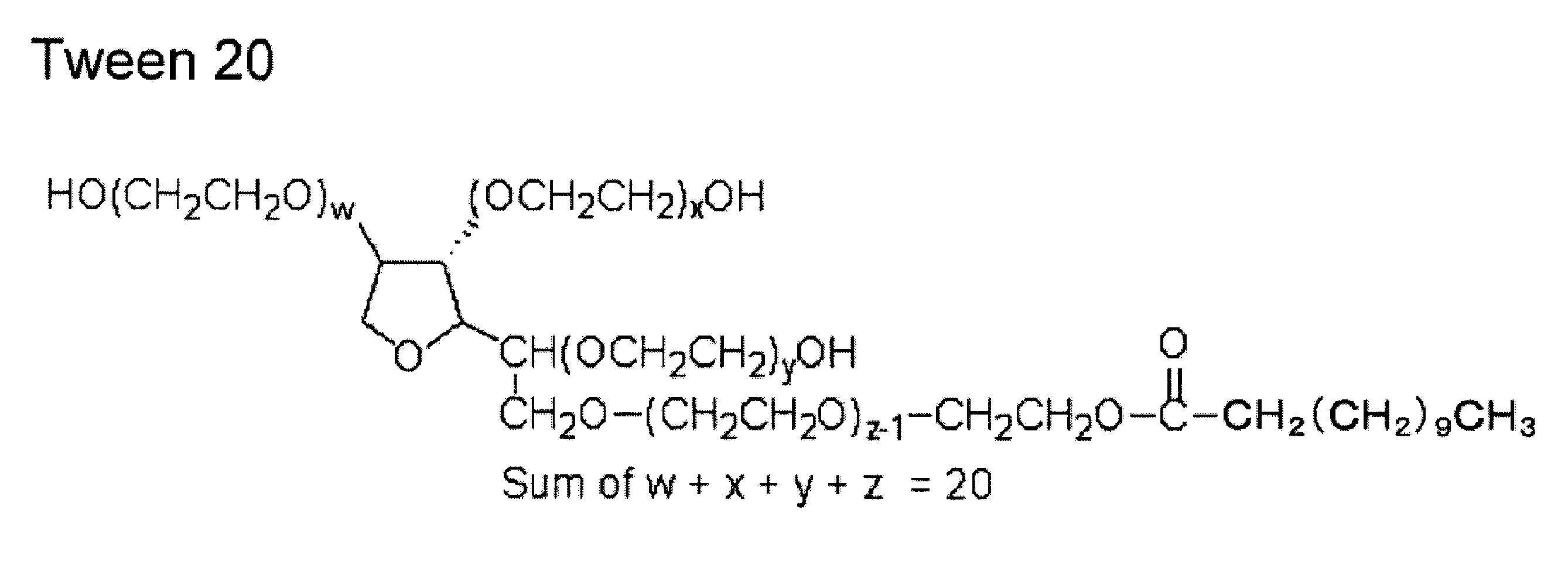
- a nonionic surfactant Tween 20 (ICI) represented by Chemical Formula 1 was used.
- ⁇ Bonding process> The substrate subjected to the above-described cleaning was placed in a 1-inch wafer tray, and after 100 ⁇ L of the prepared solution was dropped, the lid was covered to prevent drying, and the plate was allowed to stand for 10 minutes. Thereafter, 500 ⁇ L of the buffer solution alone is dropped and 500 ⁇ L of the diluted solution is sucked and removed three times. Similarly, 1 mL of ultrapure water alone is dropped and 1 mL of the diluted solution is removed by suction. After repeating 3 times, it wash
- FIG. 3 shows an SEM image of minT1-LF arranged on the vanadium portion on silicon oxide and an enlarged view of the vanadium portion.
- FIG. 4 shows an SEM image of minT1-LF arranged in the niobium portion on the silicon oxide and an enlarged view of the niobium portion.
- FIG. 5 shows an SEM image of minT1-LF placed on tantalum on silicon oxide and an enlarged view of the tantalum portion on silicon oxide.
- minT1-LF is selectively placed in the vanadium, niobium or tantalum portion.
- the number of vanadium and niobium portions arranged was 50% of minT1-LF
- the number of tantalum portions arranged was 40% or less of minT1-LF.
- Example 2 Using 50 mM MES-Tris as the buffer, using buffers adjusted to pH 6.7, 7.4, 7.8, 8.0, 8.2, ferritin concentration 2.0 mg / mL, non-ion A solution having an active surfactant concentration Tween 20 1 v / v% was prepared.
- FIG. 6 shows an SEM image of the substrate surface after the bonding step
- FIG. 7 shows the result of counting the number of minT1-LF.
- pH 7.4 or 6.7
- minT1-LF tended to aggregate in the solution, immediately after mixing at pH 6.7, and turbid after several minutes at pH 7.4. Therefore, aggregates were also found in minT1-LF disposed on the solid surface.
- FIG. 7 shows the results of measurement avoiding the aggregates, but it was difficult to obtain stable results at a pH lower than 7.4. Even at pH 7.4, there is a need to finish the operation in a short time, and a pH higher than 7.4 is preferred to obtain a stable result easily.
- the number of minT1-LF arranged in the tantalum portion was particularly high at pH 8.2 to 7.8. Although the number decreased at pH 7.4 as a boundary, in combination with the above-described influence of aggregation in the solution, good results were obtained when the pH was 7.4 or higher, preferably 7.8 or higher.
- FIG. 8 shows the result of the number of arranged minT1-LF on the silicon oxide substrate. Since the number on the silicon oxide is small, an experiment of placing the silicon oxide directly on the silicon oxide substrate was conducted including pH 8.4. The pH 6.7 to 8.2 almost overlaps with the result of the substrate whose half is vanadium, niobium or tantalum. And the adsorption number increased on the alkali side with pH 8.2 as the boundary. From this, a result was obtained that the pH was 8.2 or less, preferably 8.0 or less, and ferritin was selectively disposed in the vanadium, niobium or tantalum part.
- the result of the arrangement number of ⁇ 1-LF did not exceed 100 in 200 nm square within the range of pH 6.7 to 8.2.
- Example 3 In a solution of 50 mM MES-Tris (pH 7.8) as a buffer solution and 0.5 mg / mL as a ferritin concentration, the concentration of the nonionic surfactant Tween 20 is 0.005, 0.01, 0.1, 1, Solutions with varying amounts of 5, 10, 15, 20 v / v% were prepared. This solution was dropped on a silicon oxide / tantalum substrate to perform a bonding step.
- the nonionic surfactant Since the nonionic surfactant has a high viscosity and easily forms bubbles, reproducible results were not obtained at 15 v / v% and 20 v / v%.
- the number of arranged minT1-LF was almost constant in the tantalum portion.
- the number of arrangements rapidly increased at a concentration lower than 0.01 v / v%, with the boundary being 0.01 v / v%, and at 0.005 v / v%, it was almost the same as that on tantalum.
- the concentration of the nonionic surfactant was 0.01 v / v% or more, preferably 0.1 v / v% or more, and minT1-LF was able to obtain the arrangement selectivity to the tantalum portion.
- Example 4 A 50 mM MES-Tris (pH 7.8) as a buffer solution, a ferritin concentration of 0.5 mg / mL, and a Tween 20 1 v / v% solution as a nonionic surfactant were prepared. This solution was dropped on a 5 mm ⁇ 10 mm silicon oxide substrate on which a tantalum fine wire having a width of 20 nm and a length of 200 nm was formed, and a bonding process was performed. As a solution removal step, the solution was removed by sealing in a 1.5 mL Eppendorf tube and centrifuging at 2,000 G. minT1-LF was arranged in rows of 2 to 3 widths on the thin line. Further, on the silicon oxide substrate, minT1-LF was not observed except in the vicinity of the substrate edge and silicon fragments.
- the substrate after the bonding step was washed sequentially with a buffer solution and pure water, and the substrate surface was observed.
- minT1-LF was arranged in a single row on the thin line. Also, minT1-LF was not observed on the silicon oxide substrate.
- minT1-LF can be selectively disposed on the nano-sized tantalum portion.
- the method for arranging ferritin according to the present invention can selectively arrange ferritin and inorganic particles on the vanadium, niobium or tantalum portion on the silicon oxide substrate.
- tantalum is often used as an underlayer for metal thin films and as a diffusion prevention layer, it is useful for use in applications where a small amount of inorganic elements are selectively disposed at the interface in order to improve the metal wiring interface.
- vanadium and niobium are often used as catalysts
- a catalyst in which vanadium, niobium or tantalum is dispersed using silicon oxide as a base material ferritin containing inorganic particles used as a promoter is selectively disposed.
- the present invention can also be applied to applications for efficiently forming a catalyst-promoter junction interface on a silicon oxide substrate.
Abstract
本発明は、酸化シリコン基板上のバナジウム、ニオブまたはタンタル部分に、選択的にフェリチン及び無機粒子を配置することを目的とする。 本発明のフェリチン配置方法は、サブユニットN末端分に配列番号1に示すペプチドで修飾したフェリチンと、非イオン性界面活性剤を0.01v/v%以上、10v/v%以下含む、pH7.4以上8.2以下の溶液を調製する調製工程と、表面の一部にバナジウム、ニオブまたはタンタル部分が形成された酸化シリコン基板上に前記溶液を滴下し、ペプチド修飾フェリチンをバナジウム、ニオブまたはタンタル部分に選択的に配置させる結合工程と、を含む。結合工程後に溶液を除去することにより、配列番号1に示すペプチドで修飾したフェリチン、および該フェリチンに内包させた無機粒子を、バナジウム、ニオブまたはタンタル部分に選択的に配置することが可能である。
Description
本発明はフェリチンを酸化シリコン基板上に形成したバナジウム、ニオブまたはタンタル部分に選択的に配置させる方法に関する。また、本発明はフェリチンに内包させた無機粒子を酸化シリコン基板上のバナジウム、ニオブまたはタンタル部分に選択的に配置させる方法に関する。
従来のフェリチンあるいはフェリチンに内包させた無機粒子を固体上に配置する方法としては、リソグラフィ法により作製した静電的に極性を反転したパターン上に静電相互作用を用いて配置する方法(例えば、非特許文献5参照)が知られている。
非特許文献5では、酸化シリコン基板上にレジストを塗布し、電子ビームリソグラフィで露光した領域のレジストを現像することで除去し、酸化シリコン基板を露出させた領域を、アミノ基が末端に付いたシランカップリング剤、具体的にはアミノプロピルトリメトキシシランの蒸気に暴露することで、露出させた領域のみにアミノ末端シランカップリング剤を吸着させる。そして、レジストを溶剤で除去することで、酸化シリコン基板の一部にアミノ末端シランカップリングによりパターンを形成し、pHとイオン強度の調整により静電相互作用を制御することで、フェリチンをアミノ末端シランカップリング修飾パターンのみに配置できることが開示されている。
また、チタニウムに親和性を持つよう選ばれた6つのアミノ酸(アルギニン-リジン-ロイシン-プロリン-アスパラギン酸-アラニン:以下一文字表記でRKLPDA)からなるペプチド(非特許文献1参照)をフェリチン表面に修飾することでフェリチンにチタニウムへの親和性を付与し、さらに、非イオン性界面活性剤を用いて固体表面との相互作用を弱めることにより、チタニウムパターン上に選択配置する方法(特許文献1、非特許文献3参照)も知られている。
また、前記ペプチドRKLPDAによるチタニウム上への選択配置において、非イオン界面活性剤の吸着量の差が、選択比を増強していることが非特許文献4に開示されている。非特許文献4では疎水性基板及びシリコン基板上にはチタニウム基板上より多くの非イオン性界面活性剤が吸着することが示され、また、疎水性基板ならば多くの非イオン性界面活性剤が吸着するだろうことが示唆されているが、親水性基板であるチタニウムとシリコン上への吸着差の機構に関しては明らかにされていない。
一方、非イオン性界面活性剤の吸着量差のみを利用することで白金または酸化シリコン上の、チタンまたは窒化シリコン上へ、フェリチンの選択配置を行う方法が特許文献2に開示されている。前記ペプチドRKLPDAが親和性を持つ材料に関しては、非特許文献2において開示されており、チタニウム、シリコン、銀に親和性を持つ一方、金、クロム、白金、錫、亜鉛、銅、鉄に対しては親和性を持たないことが示されている。
すなわち、非イオン界面活性剤にはタンパク質と基板との相互作用を弱める効果があり、固体表面の吸着量差により、選択的に金や白金などの疎水性表面や酸化シリコン表面へのタンパク質の配置を抑制することができることや、ペプチドRKLPDAをタンパク質表面に修飾することにより、チタニウム、シリコン、銀に対する親和性を付与することができることがこれまでに知られている。
Ken-Ichi Sano, Kiyotake Shiba, J.A.C.S., 125, 14234(2003)
Ken-Ichi Sano, Hiroyuki Sasaki, Kiyotake Shiba, Langmuir, 21, 3090(2005)
Ichiro Yamashita, Hiroya Kirimura, Mitsuhiro Okuda, Kazuaki Nishio, Ken-Ichi Sano, Kiyotake Shiba, Tomohiro Hayashi, Masahiko Hara, Yumiko Mishima, Small, 2, 1148(2006)
Tomohiro Hayashi, Ken-Ichi Sano, Kiyotake Shiba, Yoshikazu Kumashiro, Kenji Iwahori, Ichiro Yamashita, Masahiko Hara, Nano Letters, 6, 515(2006)
Shinya Kumagai, Shigeo Yoshii, Kiyohito Yamada, Nozomu Matsukawa, Isamu Fujiwara, Kenji Iwahori, Ichiro Yamashita, Applied Physics Letters, 88, 153103(2006)
無機ナノ粒子を半導体デバイスや触媒として用いるためには、無機ナノ粒子を、シリコン基板上やシリカマトリックス中のバナジウム、ニオブまたはタンタルといった金属元素部分に高密度に選択配置する必要がある。しかしながら、静電相互作用を用いた前記従来の方法では、リソグラフィによるパターンニングが必要、かつシリコン以外の表面に高密度に吸着できるカップリング剤が必要になる。
ここで、ペプチドRKLPDAはチタニウム、シリコン、銀に対する親和性しか明らかでない一方、金、クロム、白金、錫、亜鉛、銅、鉄といった多くの元素に対しては親和性を持たないことが知られている。さらに、ペプチドRKLPDAが親和性を有するシリコン上の所望の元素に選択配置させるためには、シリコン表面への親和性の抑制と、所望の元素への吸着を同時に実現する必要がある。
上述した従来の課題を解決するための本発明方法は、
フェリチンの配置方法であって、
前記配置方法は、
サブユニットN末端部に配列番号1に記載のペプチドを修飾したフェリチンと、0.01v/v%以上10v/v%以下の非イオン界面活性剤とを含み、pHが7.4以上8.2以下の範囲にある溶液を調製する調製工程と、
表面の一部にバナジウム、ニオブ、およびタンタルから選択された1種の金属部分が形成された酸化シリコン基板上に前記溶液を滴下することによって、前記フェリチンを選択的に前記金属部分に結合させる結合工程と、
を包含する、配置方法である。
フェリチンの配置方法であって、
前記配置方法は、
サブユニットN末端部に配列番号1に記載のペプチドを修飾したフェリチンと、0.01v/v%以上10v/v%以下の非イオン界面活性剤とを含み、pHが7.4以上8.2以下の範囲にある溶液を調製する調製工程と、
表面の一部にバナジウム、ニオブ、およびタンタルから選択された1種の金属部分が形成された酸化シリコン基板上に前記溶液を滴下することによって、前記フェリチンを選択的に前記金属部分に結合させる結合工程と、
を包含する、配置方法である。
ここで、フェリチンのサブユニットN末端部をペプチドで修飾するとは、フェリチンN末端のアミノ酸残基(メチオニン残基)を配列番号1のペプチドで置換すること、フェリチンのN末端に配列番号1のペプチドを付加すること、及びフェリチンのN末端部のアミノ酸配列に配列番号1のペプチドを挿入することのいずれをも含む。
前記結合工程の後に、前記溶液を除去し、前記金属部分に選択的に結合した前記フェリチンを前記酸化シリコン基板上に残す除去工程をさらに包含することが好ましい。
前記結合工程の後に、前記フェリチンを含まない溶液により前記酸化シリコン基板の表面を洗浄し、前記金属部分に選択的に結合した前記フェリチンを、前記酸化シリコン基板上の前記金属部分に残す洗浄工程をさらに包含することも好ましい。
本発明のフェリチン配置方法では、フェリチンが無機粒子を内包していてもよい。また、前記結合工程の後に、前記酸化シリコン基板を加熱して前記フェリチンを分解し、前記フェリチンが内包していた無機粒子を、前記酸化シリコン基板上の前記金属部分に配置する分解工程をさらに包含してもよい。
フェリチンは窒素雰囲気中500℃、酸素雰囲気中400℃、オゾン雰囲気中110℃以上で熱処理することにより、酸化・分解するが、無機粒子は残る。このため、ペプチド修飾フェリチンに無機粒子を内包させれば、酸化シリコン上のバナジウム、ニオブまたはタンタル部分に選択的にフェリチンを配置した後、熱処理によりフェリチンを分解除去することにより、無機粒子のみをバナジウム、ニオブまたはタンタル部分に選択配置することが可能となる。
なお、本発明のフェリチン配置方法においては、溶液中の吸着プロセスを用いているため、基板上に構造が形成されていても、溶液が接触できる領域においては平坦な基板と本質的に違いはない。
本発明の上記目的、他の目的、特徴および利点は、添付図面参照の下、以下の好適な実施態様の詳細な説明から明らかにされる。
本発明のフェリチン配置方法によれば、酸化シリコン上の一部に形成されたバナジウム、ニオブまたはタンタル部分に、フェリチンひいてはフェリチンに内包された無機粒子を選択的に配置することができる。
以下、本発明の実施の形態について、詳細に説明する。
本発明で用いられるフェリチンは、サブユニットN末端に配列番号1で示されるアミノ酸配列を有している。一例として本発明において用いられるフェリチンは、配列番号3に示されるタンパク質のN末端の開始コドンに対応するメチオニンが配列番号1で示されるアミノ酸配列に置換されたフェリチンである。本実施の形態で用いた発現系では開始コドンに対応するメチオニンが欠失するため、このタンパク質は180残基を有し、配列番号3からメチオニンを除いた174残基のウマ由来フェリチンのアミノ酸配列のアミノ末端に配列番号1の6残基のアミノ酸配列が修飾されたものになった。
後述する実験例では、配列番号1が修飾されたフェリチンは「minT1-LF」と記述される。比較例で用いる一般のフェリチンとして、配列番号3からメチオニンが欠失した174残基からなるフェリチンを用い、これを「△1-LF」と記述する。
基板としては、熱酸化シリコン基板上に選択配置させたい金属元素のパターンが部分的に形成された基板を使用直前に洗浄して用いた。洗浄には水洗、有機溶剤洗浄、UVオゾンによる処理を順次行った。
本発明のフェリチンの選択配置方法には大きく3つの工程、すなわち調製工程、結合工程と除去工程を有する。
(1)調製工程について
調製工程では、サブユニットN末端部に配列番号1に記載のペプチドを修飾したフェリチンと、0.01v/v%以上10v/v%以下の非イオン界面活性剤とを含み、pHが7.4以上8.2以下の範囲にある溶液を調製する。
調製工程では、サブユニットN末端部に配列番号1に記載のペプチドを修飾したフェリチンと、0.01v/v%以上10v/v%以下の非イオン界面活性剤とを含み、pHが7.4以上8.2以下の範囲にある溶液を調製する。
(2)結合工程について
結合工程では、調製工程で調製した、フェリチンと非イオン界面活性剤を含む溶液を、酸化シリコン基板上に滴下する。
結合工程では、調製工程で調製した、フェリチンと非イオン界面活性剤を含む溶液を、酸化シリコン基板上に滴下する。
(3)除去工程について
除去工程では、酸化シリコン基板上に滴下した溶液中に残存しているフェリチンを除去することが目的となる。除去する方法としては、乾燥を抑制した状態で遠心により溶液を除去するか、フェリチンを含まない溶液で洗い流すことにより除去するという主に二つの方法がある。遠心による除去では、基板表面の凹凸により、除去しきれないフェリチンが残ることがあるため、フェリチンを含まない溶液で洗い流す方法が好ましい。
除去工程では、酸化シリコン基板上に滴下した溶液中に残存しているフェリチンを除去することが目的となる。除去する方法としては、乾燥を抑制した状態で遠心により溶液を除去するか、フェリチンを含まない溶液で洗い流すことにより除去するという主に二つの方法がある。遠心による除去では、基板表面の凹凸により、除去しきれないフェリチンが残ることがあるため、フェリチンを含まない溶液で洗い流す方法が好ましい。
このようにして、フェリチンを基板上に配置することができる。なお、フェリチンとして、無機粒子を内包したフェリチンを用いれば、フェリチンを分解することによって無機粒子を基板上に配置することが可能となる。
以下、本発明の実施例をさらに詳細に説明する。
(実施例1)
まず、以下の実施例に用いたフェリチンの製造方法について説明する。本願の実施例では、配列番号1に示すポリペプチドでN末端部を修飾したリコンビナントフェリチン「minT1-LF」と配列番号1を有しないリコンビナントフェリチン「△1-LF」を使用した。
まず、以下の実施例に用いたフェリチンの製造方法について説明する。本願の実施例では、配列番号1に示すポリペプチドでN末端部を修飾したリコンビナントフェリチン「minT1-LF」と配列番号1を有しないリコンビナントフェリチン「△1-LF」を使用した。
<△1-LFの製造方法>
まず、△1-LFの製造方法について説明する。天然のウマ脾臓由来フェリチンのサブユニットにはわずかに構造の異なるL型とH型があるため、天然フェリチンは、一定の構造を有さない。そこで、本願の実施例ではL型サブユニットのみから構成されるリコンビナントフェリチンを使用した。
まず、△1-LFの製造方法について説明する。天然のウマ脾臓由来フェリチンのサブユニットにはわずかに構造の異なるL型とH型があるため、天然フェリチンは、一定の構造を有さない。そこで、本願の実施例ではL型サブユニットのみから構成されるリコンビナントフェリチンを使用した。
はじめに、L型のフェリチンをコードするDNA(配列番号:2,528塩基対)を、PCR法を用いて増幅し、多量のL型フェリチンDNAを用意した。次に、このL型フェリチンDNAを、制限酵素EcoRI及びHind IIIが特異的に切断する部位(制限酵素サイト)で切断した。この切断処理により、EcoRI及びHind IIIの制限酵素サイトを有するL型フェリチンDNA断片の溶液を調製した。この溶液にDNA電気泳動を行い、L型フェリチンをコードするDNA断片だけを回収、精製した。
その後、このL型フェリチン DNA断片と、EcoRI - Hind IIIの制限酵素で処理したベクタープラスミド(pMK-2)とをインキュベートしてライゲーションを行った。これによりpMK-2プラスミドのマルチクローニングサイト(MSC)にL型フェリチンDNAが入ったベクタープラスミド pMK-2-fer-0 を作製した。使用したベクタープラスミドのpMK-2は、プロモーターに Tac プロモーターを有し、多コピープラスミドとしてコピー数が多いという特徴を持ち、大量のフェリチンを得るのに有利であることから選択した。
作製したプラスミド (pMK-2-fer-0) を宿主(ホスト)である大腸菌株E. coli Nova Blue (Novagen ) に導入(形質転換)し、リコンビナントL型フェリチン株(△1-LF)を作製した。なお、L型フェリチンサブユニットのプラスミドの主要構成と、大腸菌へのプラスミドの取り込みを模式化した図を、図2に示した。
これらのリコンビナントフェリチンの内部に、後述する方法によって無機粒子を内包させた。
<minT1-LFの製造方法>
次に、配列番号1でN末端部を修飾したフェリチン(minT1-LF)の製造方法について説明する。
次に、配列番号1でN末端部を修飾したフェリチン(minT1-LF)の製造方法について説明する。
フェリチンを構成するサブユニットのアミノ末端(N末端)をペプチドで修飾すると、図1に示したように、フェリチン粒子の外側に該ペプチドが突き出した構造となる。そのため、このN末端部分を任意のペプチドで修飾することにより、フェリチン粒子の表面を該ペプチドで修飾することが可能である。
ここで、minT1-LFの具体的な製造方法を説明する。天然フェリチン(ウマ肝臓由来)のLタイプのサブユニットの全長遺伝子を、配列番号2に示した。本実施例で用いた発現系では開始コドンに対応するメチオニンが欠失するため、配列番号2のDNAからは、配列番号3に示すアミノ酸配列のフェリチンからメチオニンを除いた174残基のアミノ酸からなるフェリチンが合成される。
まず、配列番号1をコードするDNA(配列番号4(30塩基対)及び配列番号5(22塩基対))を、PCR法を用いて増幅し、多量のDNAを用意した。
次に、上記DNAと、制限酵素Bam I及びSac Iの制限酵素で処理した、リコンビナントL型フェリチンをコードするベクタープラスミド(pMK-2)をインキュベートしてライゲーションを行った。これによりpMK-2プラスミドのマルチクローニングサイト(MSC)に、上記塩基配列のDNA及びL型フェリチンDNAが入ったベクタープラスミド(pKIS1) を作製した。pKIS1作製に使用したベクタープラスミドのpMK-2は、プロモーターに Tac プロモーターを有し、多コピープラスミドとしてコピー数が多いという特徴を持ち、大量のフェリチンを得るのに有利であることから選択した。
作製したプラスミドを宿主(ホスト)である大腸菌株 E. coli XLI Blue (Novagen) に導入(形質転換)し、配列番号1に示すポリペプチドでN末端が修飾されたL型フェリチン株(minT1-LF)を作製した。
<minT1-LFへの無機粒子の導入>
本発明において、フェリチンに内包させる無機粒子の種類は、特に限定されるものではないが、実施例においては、無機粒子として酸化第二鉄(Fe2O3)を用いた。minT1-LFへのFe2O3コアの導入は、以下のようにして行った。
本発明において、フェリチンに内包させる無機粒子の種類は、特に限定されるものではないが、実施例においては、無機粒子として酸化第二鉄(Fe2O3)を用いた。minT1-LFへのFe2O3コアの導入は、以下のようにして行った。
反応溶液として、0.5mg/mL minT1-LF/100mM HEPES-NaOH(pH7.0)を調製し、ここに5mM酢酸アンモニウム鉄を添加した。25℃で一晩反応させ、反応後の溶液からFe2O3のコアが形成されたminT1-LFを、遠心分離とゲルろ過により分子精製して回収した。遠心分離は、1,600G、10分及び10,000G、30分の条件で行って、段階的にminT1-LF以外の不要部分を沈殿として除去し、最後に残った上清よりFe2O3コアを形成したminT1-LFを、230,000G、1時間の超遠心分離によってペレットとして回収した。
得られたminT1-LFを、HPLCを用いたゲルろ過[カラム:TSK-GEL G4000WXL PEEK/流速:1ml/min/バッファ:50mM Tris-HCl(pH8.0)+150mM NaCl]を行い、24量体(約480kDa)のピークを分取した。分取したminT1-LF溶液は、限外ろ過膜を用いて濃縮し、Fe2O3を内包したminT1-LFを得た。
なお、△1-LFに上記と同様の操作を行うことにより、Fe2O3を内包した△1-LFを得た。
<基板作製方法>
次に、本願の実施例に用いた基板の作製方法について説明する。
次に、本願の実施例に用いた基板の作製方法について説明する。
10mm角の熱酸化シリコン基板の半分にレジスト(日本ゼオン:ZEP520)を塗布し、140℃3分間ベークした後に、金属元素をターゲットとしたRFマグネトロンスパッタにより金属薄膜を製膜した。ターゲットとしては純度99.5%以上(高純度化学)のバナジウム、ニオブまたはタンタルを用いた。段差による影響を排除するため、厚さは1nmとした。
40℃に加熱したリムーバー(日本ゼオン:ジメチルアセトアミド)中で超音波洗浄することにより、レジスト上の金属薄膜を除去し、半面が酸化シリコン基板、半面がバナジウム、ニオブまたはタンタルである基板を作製した。
また、ナノサイズへの選択配置が可能なことを確認するために、電子ビームリソグラフィにより細線をパターニングした基板も作製した。10mm角の熱酸化シリコン基板上に300Åのレジスト(日本ゼオン:ZEP520)をスピンコート法により塗布した後、140℃3分間ベークした。電子ビームリソグラフィ(エリオニクス:ELS-7500)により細線を露光し、現像液(日本ゼオン:n-アミルアセテート)で現像し、幅20nm長さ200nmの細線領域の表面が露出した基板を作製した。以降は半面基板と同様の方法により、タンタルの細線を作製した。
作製した基板は使用する直前に(1) 超純水中、(2) 電子工業用グレードのエタノール中、(3) 電子工業用グレードのアセトン中、で順に超音波洗浄した後、110℃に加熱しながらUVオゾナイザーで表面をクリーニングして使用した。
また、上記洗浄後の基板を原子間力顕微鏡により表面計測し、基板上に作製されたバナジウム、ニオブまたはタンタル部分が平坦な薄膜であること、及び薄膜の厚さが2nm以下であることを確認した。
<溶液調製>
次に、本願の実施例に用いた溶液の調製方法について説明する。
次に、本願の実施例に用いた溶液の調製方法について説明する。
まず、緩衝液として超純水(Millipore)、MES(Sigma-Aldrich)、Tris(Sigma-Aldrich:Trizma base)を用い、50mM、pH7.8の緩衝液を調製した。その後、フェリチンと非イオン界面活性剤とをそれぞれ0.5mg/mL、1.0v/v%となるように加えた。非イオン界面活性剤としては化1で示すTween20(ICI)を用いた。
<結合工程>
上述した洗浄を行った基板を1インチウェハートレイ中に置き、調製した溶液100μLを滴下した後、乾燥を防ぐために蓋をし、10分間静置した。その後、緩衝溶液のみを500μL滴下し、希釈された溶液を500μL吸引し除去するという工程を3回繰り返した後、同様に超純水のみを1mL滴下し、希釈された溶液を1mL吸引除去する工程を3回繰り返した後に、ビーカー中で超純水を流しながら5分間洗浄した。最後に、窒素ブローにより超純水を吹き飛ばし乾燥させた。
上述した洗浄を行った基板を1インチウェハートレイ中に置き、調製した溶液100μLを滴下した後、乾燥を防ぐために蓋をし、10分間静置した。その後、緩衝溶液のみを500μL滴下し、希釈された溶液を500μL吸引し除去するという工程を3回繰り返した後、同様に超純水のみを1mL滴下し、希釈された溶液を1mL吸引除去する工程を3回繰り返した後に、ビーカー中で超純水を流しながら5分間洗浄した。最後に、窒素ブローにより超純水を吹き飛ばし乾燥させた。
<電子顕微鏡(SEM)観察>
結合工程を行った基板に対し、高解像度電子顕微鏡(JEOL:JSM-7400F)を用いてフェリチンが内包する無機粒子コアを観察することにより、基板上のフェリチンの個数を計測した。SEM画像から200nm×200nm角の領域を切り出し、個数をカウントした。個数が100に満たない場合は3カ所の計測値を平均した。
結合工程を行った基板に対し、高解像度電子顕微鏡(JEOL:JSM-7400F)を用いてフェリチンが内包する無機粒子コアを観察することにより、基板上のフェリチンの個数を計測した。SEM画像から200nm×200nm角の領域を切り出し、個数をカウントした。個数が100に満たない場合は3カ所の計測値を平均した。
酸化シリコン上のバナジウム部分に配置されたminT1-LFのSEM画像と、バナジウム部分の拡大図を、図3に示す。また、酸化シリコン上のニオブ部分に配置されたminT1-LFのSEM画像と、ニオブ部分の拡大図を、図4に示す。また、酸化シリコン上のタンタルに配置されたminT1-LFのSEM画像と、酸化シリコン上のタンタル部分の拡大図を、図5に示す。minT1-LFは、バナジウム、ニオブまたはタンタル部分に選択的に配置されている。△1-LFの場合、バナジウム、ニオブ部分の配置個数はminT1-LFの50%、タンタル部分の配置個数は、minT1-LFの40%以下であった。
(実施例2)
緩衝液として50mMのMES-Trisを用い、pHを6.7、7.4、7.8、8.0、8.2に調製した緩衝液を用い、フェリチン濃度2.0mg/mL、非イオン性界面活性剤濃度Tween20 1v/v%とした溶液を調製した。
緩衝液として50mMのMES-Trisを用い、pHを6.7、7.4、7.8、8.0、8.2に調製した緩衝液を用い、フェリチン濃度2.0mg/mL、非イオン性界面活性剤濃度Tween20 1v/v%とした溶液を調製した。
そして、この溶液を用いて実施例1と同様の結合工程を行った。結合工程後の基板表面のSEM画像を図6に、minT1-LFの個数計測結果を図7に示す。pHが7.4もしくは6.7の場合、minT1-LFは溶液中で凝集する傾向にあり、pH6.7では混合してすぐに、pH7.4では数分後には溶液は混濁した。そのため、固体表面に配置されたminT1-LFにも凝集体が散見された。凝集体を避けて計測した結果を図7に示したが、7.4より低いpHでは安定した結果を得ることは困難だった。pH7.4においても、操作を短時間で終わらせる必要性があり、簡易に安定した結果を得るには7.4より高いpHが好ましい。
図7に見られるように、タンタル部分に配置されたminT1-LFの個数はpH8.2~7.8で特に多くなる結果が得られた。pH7.4を境界に個数は減少したが、上述した溶液中での凝集の影響と合わせて、pHは7.4以上、好ましくは7.8以上で良い結果が得られている。
一方、酸化シリコン基板上のminT1-LFの配置個数の結果を、図8に示す。酸化シリコン上の個数は少ないため、酸化シリコン基板上に直接配置する実験をpH8.4も含めて実施した。pH6.7~8.2は半面がバナジウム、ニオブまたはタンタルである基板の結果とほぼ重なる。そして、pH8.2を境界にアルカリ側で吸着個数が増加した。このことからpHは8.2以下、好ましくは8.0以下でフェリチンがバナジウム、ニオブまたはタンタル部分に選択的に配置されるという結果が得られた。
なお、△1-LFの配置個数結果は、pH6.7~8.2の範囲内では、200nm四方で100を越えることは無かった。
また、実施例1の結果と合わせて、タンパク質濃度の影響を表1にまとめたが、タンパク質濃度の影響は見られなかった。

(実施例3)
緩衝液として50mMのMES-Tris(pH7.8)、フェリチン濃度として0.5mg/mLの溶液に、非イオン性界面活性剤Tween20の濃度を0.005、0.01、0.1、1、5、10、15、20v/v%と変えた溶液を調製した。この溶液を酸化シリコン/タンタル基板上に滴下し、結合工程を行った。
緩衝液として50mMのMES-Tris(pH7.8)、フェリチン濃度として0.5mg/mLの溶液に、非イオン性界面活性剤Tween20の濃度を0.005、0.01、0.1、1、5、10、15、20v/v%と変えた溶液を調製した。この溶液を酸化シリコン/タンタル基板上に滴下し、結合工程を行った。
非イオン性界面活性剤は粘度が高く、また、気泡ができやすいため、15v/v%および20v/v%では再現性のある結果が得られなかった。minT1-LFの配置個数は、タンタル部分ではほぼ一定だった。酸化シリコン基板上では、0.01v/v%を境界に、0.01v/v%より低い濃度では配置個数は急激に増加し、0.005v/v%ではタンタル上とほぼ同数だった。以上の結果から、非イオン性界面活性剤の濃度としては0.01v/v%以上、好ましくは0.1v/v%以上で、minT1-LFはタンタル部分への配置選択性が得られた。
なお、界面活性剤として、化2で示すTween80を用いても同様の結果が得られた。

(実施例4)
緩衝液として50mMのMES-Tris(pH7.8)、フェリチン濃度として0.5mg/mL、非イオン性界面活性剤としてTween20 1v/v%の溶液を調製した。この溶液を、幅20nm、長さ200nmのタンタル細線を形成した5mm×10mmの酸化シリコン基板上に滴下し、結合工程を行った。溶液の除去工程として、容量1.5mLのエッペンドルフチューブの中に封入し、2,000Gで遠心することで溶液を除去した。minT1-LFは、細線上に幅2~3個の列で配置された。また、酸化シリコン基板上には、基板端とシリコンかけらゴミ近傍以外にはminT1-LFは見られなかった。
緩衝液として50mMのMES-Tris(pH7.8)、フェリチン濃度として0.5mg/mL、非イオン性界面活性剤としてTween20 1v/v%の溶液を調製した。この溶液を、幅20nm、長さ200nmのタンタル細線を形成した5mm×10mmの酸化シリコン基板上に滴下し、結合工程を行った。溶液の除去工程として、容量1.5mLのエッペンドルフチューブの中に封入し、2,000Gで遠心することで溶液を除去した。minT1-LFは、細線上に幅2~3個の列で配置された。また、酸化シリコン基板上には、基板端とシリコンかけらゴミ近傍以外にはminT1-LFは見られなかった。
溶液の洗浄工程として、緩衝液と純水により結合工程後の基板を順次洗浄し、基板表面を観察したところ、minT1-LFは細線上に幅1個の列で配置された。また、酸化シリコン基板上にはminT1-LFは見られなかった。
以上のように、本発明によって、minT1-LFはナノサイズのタンタル部分への選択的な配置が可能であった。
なお、フェリチン内に内包させる無機粒子として、酸化第二鉄に替えてコバルト酸化物を用いても、同様の結果が得られた。また、インジウム酸化物を内包したminT1-LFでは、インジウム酸化物粒子が、SEMの電子ビーム照射により二次電子輝度が失われる(おそらく蒸発したためと推察される)ために、正確な個数の比較は困難であったが、低倍率の簡易な個数計測で、ほぼ同様の結果が得られた。
上記説明から、当業者にとっては、本発明の多くの改良や他の実施の形態が明らかである。したがって、上記説明は例示としてのみ解釈されるべきであり、本発明を実行する最良の態様を当業者に教示する目的で提供されたものである。本発明の精神を逸脱することなく、その構造および/または機能の詳細を実質的に変更できる。
本発明にかかるフェリチンの配置方法は、酸化シリコン基板上のバナジウム、ニオブまたはタンタル部分に、フェリチン及び無機粒子を選択配置することが可能である。
タンタルは金属薄膜の下地層や、拡散防止層としてよく用いられることから、金属配線界面改善の為に微量の無機元素を界面に選択的に配置する用途に用いることに有用である。
また、バナジウムやニオブは触媒としてよく用いられることから、酸化シリコンを基材とし、バナジウムやニオブやタンタルを分散した触媒において、助触媒として用いる無機粒子を内包したフェリチンを選択的に配置することにより、効率的に触媒-助触媒接合界面を酸化シリコン基材上に形成する用途にも応用できる。
Claims (5)
- フェリチンの配置方法であって、
前記配置方法は、
サブユニットN末端部に配列番号1に記載のペプチドを修飾したフェリチンと、0.01v/v%以上10v/v%以下の非イオン界面活性剤とを含み、pHが7.4以上8.2以下の範囲にある溶液を調製する調製工程と、
表面の一部にバナジウム、ニオブ、およびタンタルから選択された1種の金属部分が形成された酸化シリコン基板上に前記溶液を滴下することによって、前記フェリチンを選択的に前記金属部分に結合させる結合工程と、
を包含する、配置方法。 - 前記結合工程の後に、前記溶液を除去し、前記金属部分に選択的に結合した前記フェリチンを前記酸化シリコン基板上に残す除去工程をさらに包含する、請求項1に記載のフェリチンの配置方法。
- 前記結合工程の後に、前記フェリチンを含まない溶液により前記酸化シリコン基板の表面を洗浄し、前記金属部分に選択的に結合した前記フェリチンを、前記酸化シリコン基板上の前記金属部分に残す洗浄工程をさらに包含する、請求項1に記載のフェリチンの配置方法。
- 前記フェリチンが無機粒子を内包している、請求項1に記載の方法。
- 前記結合工程の後に、前記酸化シリコン基板を加熱して前記フェリチンを分解し、前記フェリチンが内包していた無機粒子を、前記酸化シリコン基板上の前記金属部分に配置する分解工程をさらに包含する、請求項4に記載の方法。
Priority Applications (2)
| Application Number | Priority Date | Filing Date | Title |
|---|---|---|---|
| JP2010548972A JP4834788B2 (ja) | 2009-05-21 | 2009-10-07 | フェリチンの配置方法 |
| US13/299,737 US9090710B2 (en) | 2009-05-21 | 2011-11-18 | Method of arraying ferritin |
Applications Claiming Priority (2)
| Application Number | Priority Date | Filing Date | Title |
|---|---|---|---|
| JP2009-122867 | 2009-05-21 | ||
| JP2009122867 | 2009-05-21 |
Related Child Applications (1)
| Application Number | Title | Priority Date | Filing Date |
|---|---|---|---|
| US13/299,737 Continuation US9090710B2 (en) | 2009-05-21 | 2011-11-18 | Method of arraying ferritin |
Publications (1)
| Publication Number | Publication Date |
|---|---|
| WO2010134139A1 true WO2010134139A1 (ja) | 2010-11-25 |
Family
ID=43125839
Family Applications (1)
| Application Number | Title | Priority Date | Filing Date |
|---|---|---|---|
| PCT/JP2009/005204 WO2010134139A1 (ja) | 2009-05-21 | 2009-10-07 | フェリチンの配置方法 |
Country Status (3)
| Country | Link |
|---|---|
| US (1) | US9090710B2 (ja) |
| JP (1) | JP4834788B2 (ja) |
| WO (1) | WO2010134139A1 (ja) |
Cited By (3)
| Publication number | Priority date | Publication date | Assignee | Title |
|---|---|---|---|---|
| WO2021064909A1 (ja) * | 2019-10-02 | 2021-04-08 | シャープ株式会社 | 表示装置、および表示装置の製造方法 |
| WO2021064910A1 (ja) * | 2019-10-02 | 2021-04-08 | シャープ株式会社 | 表示装置、および表示装置の製造方法 |
| WO2021156935A1 (ja) * | 2020-02-04 | 2021-08-12 | シャープ株式会社 | 発光素子、及び発光素子の製造方法 |
Families Citing this family (3)
| Publication number | Priority date | Publication date | Assignee | Title |
|---|---|---|---|---|
| JP4834789B2 (ja) * | 2009-05-22 | 2011-12-14 | パナソニック株式会社 | フェリチンの配置方法 |
| KR101552323B1 (ko) | 2013-08-09 | 2015-09-14 | 한국과학기술원 | 페리틴을 이용한 나노 촉매를 포함하는 다공성 금속산화물 반도체 나노 구조체를 이용한 가스 센서용 부재, 가스 센서 및 그 제조 방법 |
| KR20220057542A (ko) * | 2019-09-05 | 2022-05-09 | 아지노모토 가부시키가이샤 | 펩타이드 내포 페리틴 |
Citations (4)
| Publication number | Priority date | Publication date | Assignee | Title |
|---|---|---|---|---|
| JP2005524000A (ja) * | 2002-04-23 | 2005-08-11 | ナンテロ,インク. | カーボンナノチューブ膜、層、ファブリック、リボン、素子及び製品を製造するために予備成形ナノチューブを使用する方法 |
| WO2006064639A1 (ja) * | 2004-12-14 | 2006-06-22 | Matsushita Electric Industrial Co., Ltd. | チタン結合性フェリチン及び無機粒子の配置方法 |
| JP2008054599A (ja) * | 2006-08-31 | 2008-03-13 | Okayama Univ | Ss25ペプチド、ss25’ペプチド、および/またはクッションタンパク質を含む、クッション性吸着剤 |
| JP2009007339A (ja) * | 2007-05-30 | 2009-01-15 | Sanyo Chem Ind Ltd | 歯科用インプラント用接着剤 |
Family Cites Families (2)
| Publication number | Priority date | Publication date | Assignee | Title |
|---|---|---|---|---|
| WO2006064640A1 (ja) | 2004-12-14 | 2006-06-22 | Matsushita Electric Industrial Co., Ltd. | フェリチンの選択的配置方法 |
| JP4834789B2 (ja) * | 2009-05-22 | 2011-12-14 | パナソニック株式会社 | フェリチンの配置方法 |
-
2009
- 2009-10-07 JP JP2010548972A patent/JP4834788B2/ja not_active Expired - Fee Related
- 2009-10-07 WO PCT/JP2009/005204 patent/WO2010134139A1/ja active Application Filing
-
2011
- 2011-11-18 US US13/299,737 patent/US9090710B2/en active Active
Patent Citations (4)
| Publication number | Priority date | Publication date | Assignee | Title |
|---|---|---|---|---|
| JP2005524000A (ja) * | 2002-04-23 | 2005-08-11 | ナンテロ,インク. | カーボンナノチューブ膜、層、ファブリック、リボン、素子及び製品を製造するために予備成形ナノチューブを使用する方法 |
| WO2006064639A1 (ja) * | 2004-12-14 | 2006-06-22 | Matsushita Electric Industrial Co., Ltd. | チタン結合性フェリチン及び無機粒子の配置方法 |
| JP2008054599A (ja) * | 2006-08-31 | 2008-03-13 | Okayama Univ | Ss25ペプチド、ss25’ペプチド、および/またはクッションタンパク質を含む、クッション性吸着剤 |
| JP2009007339A (ja) * | 2007-05-30 | 2009-01-15 | Sanyo Chem Ind Ltd | 歯科用インプラント用接着剤 |
Non-Patent Citations (3)
| Title |
|---|
| KEN-ICHI SANO ET AL.: "In Aqua Manufacturing of a Three-Dimensional Nanostructure Using a Peptide Aptamer", MRS BULLETIN, vol. 33, May 2008 (2008-05-01), pages 524 - 529 * |
| KEN-ICHI SANO ET AL.: "Specificity and Biomineralization Activities of Ti-Binding Peptide-1 (TBP-1)", LANGMUIR, vol. 21, 23 February 2005 (2005-02-23), pages 3090 - 3095, XP003002763, DOI: doi:10.1021/la047428m * |
| KENNETH DOUGLAS ET AL.: "Biomolecular/Solid-satate nanoheterostructures", APPLIED PHYSICS LETTERS, vol. 56, no. 7, 12 February 1990 (1990-02-12), pages 692 - 694, XP000126704, DOI: doi:10.1063/1.102685 * |
Cited By (3)
| Publication number | Priority date | Publication date | Assignee | Title |
|---|---|---|---|---|
| WO2021064909A1 (ja) * | 2019-10-02 | 2021-04-08 | シャープ株式会社 | 表示装置、および表示装置の製造方法 |
| WO2021064910A1 (ja) * | 2019-10-02 | 2021-04-08 | シャープ株式会社 | 表示装置、および表示装置の製造方法 |
| WO2021156935A1 (ja) * | 2020-02-04 | 2021-08-12 | シャープ株式会社 | 発光素子、及び発光素子の製造方法 |
Also Published As
| Publication number | Publication date |
|---|---|
| JP4834788B2 (ja) | 2011-12-14 |
| US9090710B2 (en) | 2015-07-28 |
| US20120116061A1 (en) | 2012-05-10 |
| JPWO2010134139A1 (ja) | 2012-11-08 |
Similar Documents
| Publication | Publication Date | Title |
|---|---|---|
| JP4834788B2 (ja) | フェリチンの配置方法 | |
| JP4843505B2 (ja) | ナノ黒鉛構造体−金属ナノ粒子複合体 | |
| US7419849B2 (en) | Method for producing single electron semiconductor element | |
| JP3916653B2 (ja) | チタン結合性フェリチン及び無機粒子の配置方法 | |
| JP4015177B2 (ja) | フェリチンの選択的配置方法 | |
| US7514063B1 (en) | Method for the purification of semiconducting single walled carbon nanotubes | |
| US20070112548A1 (en) | Methods for fabricating micro-to-nanoscale devices via biologically-induced solid formation on biologically-derived templates, and micro-to-nanoscale structures and micro-to-nanoscale devices made thereby | |
| JP4834789B2 (ja) | フェリチンの配置方法 | |
| WO2001068513A1 (fr) | Procede destine a usiner une microstructure avec precision | |
| JP2010270059A (ja) | フェリチンの配置方法 | |
| JP5311806B2 (ja) | バイオシリカ製造法、およびバイオシリカ固定基板の製造法 | |
| JP2005335054A (ja) | 金属ナノワイヤー及びその製造方法 | |
| JP2006187845A (ja) | 微粒子固定方法 | |
| JP4291407B2 (ja) | フェリチン配置方法および無機粒子配置方法 | |
| Tomizaki et al. | Synthesis of silica nanofibers templated by self-assembled peptide nanostructures | |
| JP2010240794A (ja) | カーボンナノチューブ配置方法 | |
| JP2008290962A (ja) | アポフェリチン | |
| JP2006190883A (ja) | 微粒子形成方法 | |
| Lee et al. | Preparation of a self-assembled cytochrome c monolayer on a gold substrate for biomolecular device architecture | |
| JP6348324B2 (ja) | ナノ粒子−GroEL蛋白質複合体及びその製造方法 | |
| JP5208403B2 (ja) | 基材表面修飾方法 | |
| Adigun et al. | Bioinspired Systems | |
| JP2016149969A (ja) | ニオブ材料結合ペプチド | |
| JP2008188753A (ja) | フェリチンを基板上に二次元配列させる方法 |
Legal Events
| Date | Code | Title | Description |
|---|---|---|---|
| ENP | Entry into the national phase |
Ref document number: 2010548972 Country of ref document: JP Kind code of ref document: A |
|
| 121 | Ep: the epo has been informed by wipo that ep was designated in this application |
Ref document number: 09844873 Country of ref document: EP Kind code of ref document: A1 |
|
| NENP | Non-entry into the national phase |
Ref country code: DE |
|
| 122 | Ep: pct application non-entry in european phase |
Ref document number: 09844873 Country of ref document: EP Kind code of ref document: A1 |