WO2010055737A1 - 操作デバイス - Google Patents
操作デバイス Download PDFInfo
- Publication number
- WO2010055737A1 WO2010055737A1 PCT/JP2009/067174 JP2009067174W WO2010055737A1 WO 2010055737 A1 WO2010055737 A1 WO 2010055737A1 JP 2009067174 W JP2009067174 W JP 2009067174W WO 2010055737 A1 WO2010055737 A1 WO 2010055737A1
- Authority
- WO
- WIPO (PCT)
- Prior art keywords
- operation device
- light
- light emitting
- information processing
- emitting unit
- Prior art date
Links
Images


Classifications
-
- G—PHYSICS
- G06—COMPUTING; CALCULATING OR COUNTING
- G06F—ELECTRIC DIGITAL DATA PROCESSING
- G06F3/00—Input arrangements for transferring data to be processed into a form capable of being handled by the computer; Output arrangements for transferring data from processing unit to output unit, e.g. interface arrangements
- G06F3/01—Input arrangements or combined input and output arrangements for interaction between user and computer
- G06F3/03—Arrangements for converting the position or the displacement of a member into a coded form
- G06F3/033—Pointing devices displaced or positioned by the user, e.g. mice, trackballs, pens or joysticks; Accessories therefor
- G06F3/0346—Pointing devices displaced or positioned by the user, e.g. mice, trackballs, pens or joysticks; Accessories therefor with detection of the device orientation or free movement in a 3D space, e.g. 3D mice, 6-DOF [six degrees of freedom] pointers using gyroscopes, accelerometers or tilt-sensors
-
- A—HUMAN NECESSITIES
- A63—SPORTS; GAMES; AMUSEMENTS
- A63F—CARD, BOARD, OR ROULETTE GAMES; INDOOR GAMES USING SMALL MOVING PLAYING BODIES; VIDEO GAMES; GAMES NOT OTHERWISE PROVIDED FOR
- A63F13/00—Video games, i.e. games using an electronically generated display having two or more dimensions
- A63F13/20—Input arrangements for video game devices
- A63F13/21—Input arrangements for video game devices characterised by their sensors, purposes or types
- A63F13/211—Input arrangements for video game devices characterised by their sensors, purposes or types using inertial sensors, e.g. accelerometers or gyroscopes
-
- A—HUMAN NECESSITIES
- A63—SPORTS; GAMES; AMUSEMENTS
- A63F—CARD, BOARD, OR ROULETTE GAMES; INDOOR GAMES USING SMALL MOVING PLAYING BODIES; VIDEO GAMES; GAMES NOT OTHERWISE PROVIDED FOR
- A63F13/00—Video games, i.e. games using an electronically generated display having two or more dimensions
- A63F13/20—Input arrangements for video game devices
- A63F13/21—Input arrangements for video game devices characterised by their sensors, purposes or types
- A63F13/213—Input arrangements for video game devices characterised by their sensors, purposes or types comprising photodetecting means, e.g. cameras, photodiodes or infrared cells
-
- A—HUMAN NECESSITIES
- A63—SPORTS; GAMES; AMUSEMENTS
- A63F—CARD, BOARD, OR ROULETTE GAMES; INDOOR GAMES USING SMALL MOVING PLAYING BODIES; VIDEO GAMES; GAMES NOT OTHERWISE PROVIDED FOR
- A63F13/00—Video games, i.e. games using an electronically generated display having two or more dimensions
- A63F13/20—Input arrangements for video game devices
- A63F13/24—Constructional details thereof, e.g. game controllers with detachable joystick handles
-
- A—HUMAN NECESSITIES
- A63—SPORTS; GAMES; AMUSEMENTS
- A63F—CARD, BOARD, OR ROULETTE GAMES; INDOOR GAMES USING SMALL MOVING PLAYING BODIES; VIDEO GAMES; GAMES NOT OTHERWISE PROVIDED FOR
- A63F13/00—Video games, i.e. games using an electronically generated display having two or more dimensions
- A63F13/25—Output arrangements for video game devices
- A63F13/28—Output arrangements for video game devices responding to control signals received from the game device for affecting ambient conditions, e.g. for vibrating players' seats, activating scent dispensers or affecting temperature or light
-
- A—HUMAN NECESSITIES
- A63—SPORTS; GAMES; AMUSEMENTS
- A63F—CARD, BOARD, OR ROULETTE GAMES; INDOOR GAMES USING SMALL MOVING PLAYING BODIES; VIDEO GAMES; GAMES NOT OTHERWISE PROVIDED FOR
- A63F13/00—Video games, i.e. games using an electronically generated display having two or more dimensions
- A63F13/20—Input arrangements for video game devices
- A63F13/21—Input arrangements for video game devices characterised by their sensors, purposes or types
- A63F13/215—Input arrangements for video game devices characterised by their sensors, purposes or types comprising means for detecting acoustic signals, e.g. using a microphone
-
- A—HUMAN NECESSITIES
- A63—SPORTS; GAMES; AMUSEMENTS
- A63F—CARD, BOARD, OR ROULETTE GAMES; INDOOR GAMES USING SMALL MOVING PLAYING BODIES; VIDEO GAMES; GAMES NOT OTHERWISE PROVIDED FOR
- A63F13/00—Video games, i.e. games using an electronically generated display having two or more dimensions
- A63F13/20—Input arrangements for video game devices
- A63F13/23—Input arrangements for video game devices for interfacing with the game device, e.g. specific interfaces between game controller and console
- A63F13/235—Input arrangements for video game devices for interfacing with the game device, e.g. specific interfaces between game controller and console using a wireless connection, e.g. infrared or piconet
-
- A—HUMAN NECESSITIES
- A63—SPORTS; GAMES; AMUSEMENTS
- A63F—CARD, BOARD, OR ROULETTE GAMES; INDOOR GAMES USING SMALL MOVING PLAYING BODIES; VIDEO GAMES; GAMES NOT OTHERWISE PROVIDED FOR
- A63F2300/00—Features of games using an electronically generated display having two or more dimensions, e.g. on a television screen, showing representations related to the game
- A63F2300/10—Features of games using an electronically generated display having two or more dimensions, e.g. on a television screen, showing representations related to the game characterized by input arrangements for converting player-generated signals into game device control signals
- A63F2300/1025—Features of games using an electronically generated display having two or more dimensions, e.g. on a television screen, showing representations related to the game characterized by input arrangements for converting player-generated signals into game device control signals details of the interface with the game device, e.g. USB version detection
- A63F2300/1031—Features of games using an electronically generated display having two or more dimensions, e.g. on a television screen, showing representations related to the game characterized by input arrangements for converting player-generated signals into game device control signals details of the interface with the game device, e.g. USB version detection using a wireless connection, e.g. Bluetooth, infrared connections
-
- A—HUMAN NECESSITIES
- A63—SPORTS; GAMES; AMUSEMENTS
- A63F—CARD, BOARD, OR ROULETTE GAMES; INDOOR GAMES USING SMALL MOVING PLAYING BODIES; VIDEO GAMES; GAMES NOT OTHERWISE PROVIDED FOR
- A63F2300/00—Features of games using an electronically generated display having two or more dimensions, e.g. on a television screen, showing representations related to the game
- A63F2300/10—Features of games using an electronically generated display having two or more dimensions, e.g. on a television screen, showing representations related to the game characterized by input arrangements for converting player-generated signals into game device control signals
- A63F2300/1043—Features of games using an electronically generated display having two or more dimensions, e.g. on a television screen, showing representations related to the game characterized by input arrangements for converting player-generated signals into game device control signals being characterized by constructional details
-
- A—HUMAN NECESSITIES
- A63—SPORTS; GAMES; AMUSEMENTS
- A63F—CARD, BOARD, OR ROULETTE GAMES; INDOOR GAMES USING SMALL MOVING PLAYING BODIES; VIDEO GAMES; GAMES NOT OTHERWISE PROVIDED FOR
- A63F2300/00—Features of games using an electronically generated display having two or more dimensions, e.g. on a television screen, showing representations related to the game
- A63F2300/10—Features of games using an electronically generated display having two or more dimensions, e.g. on a television screen, showing representations related to the game characterized by input arrangements for converting player-generated signals into game device control signals
- A63F2300/105—Features of games using an electronically generated display having two or more dimensions, e.g. on a television screen, showing representations related to the game characterized by input arrangements for converting player-generated signals into game device control signals using inertial sensors, e.g. accelerometers, gyroscopes
-
- A—HUMAN NECESSITIES
- A63—SPORTS; GAMES; AMUSEMENTS
- A63F—CARD, BOARD, OR ROULETTE GAMES; INDOOR GAMES USING SMALL MOVING PLAYING BODIES; VIDEO GAMES; GAMES NOT OTHERWISE PROVIDED FOR
- A63F2300/00—Features of games using an electronically generated display having two or more dimensions, e.g. on a television screen, showing representations related to the game
- A63F2300/10—Features of games using an electronically generated display having two or more dimensions, e.g. on a television screen, showing representations related to the game characterized by input arrangements for converting player-generated signals into game device control signals
- A63F2300/1081—Input via voice recognition
-
- A—HUMAN NECESSITIES
- A63—SPORTS; GAMES; AMUSEMENTS
- A63F—CARD, BOARD, OR ROULETTE GAMES; INDOOR GAMES USING SMALL MOVING PLAYING BODIES; VIDEO GAMES; GAMES NOT OTHERWISE PROVIDED FOR
- A63F2300/00—Features of games using an electronically generated display having two or more dimensions, e.g. on a television screen, showing representations related to the game
- A63F2300/10—Features of games using an electronically generated display having two or more dimensions, e.g. on a television screen, showing representations related to the game characterized by input arrangements for converting player-generated signals into game device control signals
- A63F2300/1087—Features of games using an electronically generated display having two or more dimensions, e.g. on a television screen, showing representations related to the game characterized by input arrangements for converting player-generated signals into game device control signals comprising photodetecting means, e.g. a camera
- A63F2300/1093—Features of games using an electronically generated display having two or more dimensions, e.g. on a television screen, showing representations related to the game characterized by input arrangements for converting player-generated signals into game device control signals comprising photodetecting means, e.g. a camera using visible light
-
- A—HUMAN NECESSITIES
- A63—SPORTS; GAMES; AMUSEMENTS
- A63F—CARD, BOARD, OR ROULETTE GAMES; INDOOR GAMES USING SMALL MOVING PLAYING BODIES; VIDEO GAMES; GAMES NOT OTHERWISE PROVIDED FOR
- A63F2300/00—Features of games using an electronically generated display having two or more dimensions, e.g. on a television screen, showing representations related to the game
- A63F2300/30—Features of games using an electronically generated display having two or more dimensions, e.g. on a television screen, showing representations related to the game characterized by output arrangements for receiving control signals generated by the game device
- A63F2300/302—Features of games using an electronically generated display having two or more dimensions, e.g. on a television screen, showing representations related to the game characterized by output arrangements for receiving control signals generated by the game device specially adapted for receiving control signals not targeted to a display device or game input means, e.g. vibrating driver's seat, scent dispenser
Definitions
- the present invention relates to an operation device, and more particularly to an operation device including a light emitting body photographed by a camera.
- the distance between the camera and the light emitter is recognized based on the size of the area where the light emitter is projected in the captured image.
- the size of the area where the light emitter is displayed in the captured image changes depending on the brightness of the background of the light emitter in the captured image. That is, when the background is bright, the light emitter is projected to be small due to the influence of ambient light. Conversely, when the background is dark, the light emitter is projected large. For this reason, when recognizing the distance of a camera and a light-emitting body by the magnitude
- each operation device may be connected to the information processing apparatus. Thereby, it becomes possible for a plurality of users to perform operation input to the information processing apparatus.
- each user may be unable to know which operation device he / she is using once he / she releases the operation device he / she is using.
- each operation device may be provided with an indicator or the like for displaying information for distinguishing from other operation devices.
- a specific example of this information is a logical number (port number) assigned by the information processing apparatus.
- such display of an indicator or the like may cause erroneous detection when detecting the position of the operation device with light from the light emitter.
- the user of the operation device wants to check various device states as necessary, for example, a charging state of a rechargeable battery built in the operation device.
- the operation device is provided with an indicator or the like for displaying such a device state, the display of the indicator or the like may cause a false detection when the position of the operation device is detected by light from the light emitter. is there.
- the present invention has been made in view of the above problems, and one of its purposes is to provide an operation device that can input various operation information to the main body as necessary without unnecessarily increasing the weight of the operation device. It is to provide.
- Another object of the present invention is to provide an operation device in which the size of the light emitter is correctly projected by the camera regardless of the brightness of the background.
- Still another object of the present invention is to provide an information processing system, an operation device, an information processing apparatus, a control method thereof, and an information storage medium that allow a user to easily distinguish a plurality of operation devices.
- Still another object of the present invention is to provide an information processing system, an operation device, an information processing apparatus, a control method thereof, and an information storage medium that allow the user to easily grasp the device state of the operation device.
- An operation device includes a main body having a shape extending from one end toward the other end, a light emitter provided at the one end of the main body, a plurality of light emitting bodies provided at the other end of the main body, A connection unit to which any one of the other operation devices is connected.
- the operation device may include a plurality of additional operation modules each including an input member that inputs information.
- One of the plurality of additional operation modules is provided on the opposite side of the connected portion connected to the connection portion and the other connected portion, and the other one of the plurality of additional operation modules is You may provide the additional connection part which has the same shape as the said connection part of the said main body so that it may connect in series.
- each of the additional operation modules may include identification information storage means for storing identification information for identifying the type of the additional operation module.
- the main body may include identification information acquisition means for acquiring the identification information from the identification information storage means included in the additional operation module connected directly or indirectly to the main body.
- the main body may include order determining means for determining the order of the additional operation modules connected in series to the main body.
- Each of the additional operation modules includes a signal line connected in series when the additional operation module is connected in series to the main body, and a voltmeter that measures a voltage at a predetermined position on the signal line. It's okay.
- the main body may include a power supply that applies a predetermined voltage from one end side to the signal lines connected in series.
- the order determining means may determine the order of the additional operation modules connected in series to the main body based on the voltage measured in each voltmeter.
- one of the plurality of additional operation modules may include a rotation mechanism between the connected portion and the input member so as to change the orientation of the input member with respect to the main body.
- one of the plurality of additional operation modules may be configured to connect to the main body or another additional operation module in a plurality of directions.
- a determination means for determining the direction of the input member provided in the one additional operation module may be included.
- the one additional operation module may include a sensor that detects the posture of the additional operation module
- the main body may include a sensor that detects the posture of the main body.
- the determination unit is provided in the one additional operation module based on a detection result by the sensor included in the main body and a detection result by the sensor included in the one additional operation module. The orientation of the input member that is provided with respect to the main body may be determined.
- the operation device is formed in a hollow shape by a light emitting element and a light diffusing material that diffuses light emitted from the light emitting element and receives light emitted from the light emitting element.
- An inner shell is provided, and a colored and translucent outer shell covering the outside of the inner shell.
- a low reflection film may be formed on the surface of the outer shell.
- the outer shell may be integrally formed with a mechanism for attaching to the main body.
- An information processing system is an information processing system including a plurality of operation devices each having a light emitting unit, and an information processing apparatus that is connected to the plurality of operation devices.
- the information processing apparatus includes: a detecting unit that detects light emitted from the light emitting unit; and a position specifying unit that specifies a position of each operation device according to the position of the detected light.
- Each of the operation devices is characterized in that the light emitting unit emits light with different emission colors.
- the information processing apparatus assigns a logical number for identifying the operation device to each of the operation devices connected to the communication, and each of the plurality of operation devices
- the light emitting unit may emit light with a light emission color determined according to the logical number to which the operation device is assigned.
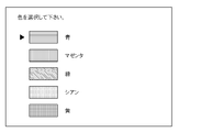
- the information processing apparatus presents a light emission color candidate to the user of the operation device, and the operation device held by the user in a color selected by the user from the light emission color candidates
- the light emitting control unit may further include a light emission control unit that transmits an instruction to cause the light emitting unit to emit light to the operation device, and the operation device may cause the light emitting unit to emit light in a color corresponding to the transmitted instruction.
- the light emission control means may exclude light emission colors of other operation devices from the light emission color candidates to be presented.
- An operation device is an operation device that includes a light-emitting unit and is connected to an information processing apparatus in communication, and the light emitted from the light-emitting unit is positioned by the information processing apparatus.
- the light emitting unit emits light with a light emission color different from that of other operation devices connected to the information processing apparatus.
- an information processing apparatus is an information processing apparatus that is communicatively connected to a plurality of operation devices each including a light emitting unit, and a detection unit that detects light emitted from the light emitting unit; According to the detected light position, the position specifying means for specifying the position of each operation device, and the light emitting unit of the operation device emits light with different emission colors for each of the plurality of operation devices.
- Light emission control means for specifying the position of each operation device, and the light emitting unit of the operation device emits light with different emission colors for each of the plurality of operation devices.
- a control method for an information processing apparatus which is a control method for an information processing apparatus that is connected to a plurality of operation devices each including a light emitting unit, and that emits light emitted from the light emitting unit.
- an information storage medium includes: an information processing device that is connected to a plurality of operation devices each including a light emitting unit and includes a detection unit that detects light emitted from the light emitting unit.
- a position specifying means for specifying the position of each operation device according to the position of the emitted light, and light emission for causing each of the plurality of operation devices to emit the light emitting portions of the operation devices in different emission colors
- a computer-readable information storage medium that stores a program for functioning as control means.
- An information processing system is an information processing system including an operation device including a light emitting unit and an information processing device, and the information processing device emits light emitted from the light emitting unit.
- Detecting means for detecting the position of the operating device according to the position of the detected light, and the operating device according to the device state of the operating device. The light emission mode of the light emitting unit is changed.
- the operation device may change a light emission mode of the light emitting unit according to a charge state of a rechargeable battery built in the operation device.
- the operation device may change the emission color of the light emitting unit when the remaining charge of the rechargeable battery falls below a predetermined threshold.
- the operation device may cause the light emitting unit to emit light in a manner corresponding to a charged state of the rechargeable battery in accordance with a user instruction.
- An operating device is an operating device including a light emitting unit, and light emitted from the light emitting unit is used for specifying a position of the operating device by an information processing device.
- the light emission mode of the light emitting unit is changed according to the device state.
- An information processing apparatus is an information processing apparatus that is connected to an operation device including a light-emitting unit.
- the detection unit detects light emitted from the light-emitting unit.
- Position specifying means for specifying the position of the operation device according to the position of the light, means for acquiring the device state of the operation device, and light emission of the light emitting unit according to the acquired device state of the operation device.
- a light emission control means for changing the mode.
- a control method for an information processing device is a control method for an information processing device that is communicatively connected to an operation device including a light emitting unit, and the step of detecting light emitted from the light emitting unit Determining the position of the operation device according to the detected position of the light; acquiring the device state of the operation device; and emitting the light according to the acquired device state of the operation device. And changing the light emission mode of the part.
- an information storage medium includes an information processing device that includes a detection unit that is connected to an operation device including a light-emitting unit and detects light emitted from the light-emitting unit.
- the position specifying means for specifying the position of the operation device, the means for acquiring the device state of the operation device, and the light emission mode of the light emitting unit according to the acquired device state of the operation device.
- a computer-readable information storage medium that stores a program for causing it to function as a light emission control means.
- FIG. 1 It is a figure which shows a mode that the operation information of a game is input using the operation device which concerns on the 1st Embodiment of this invention.
- It is a block diagram of a game system. It is a figure which shows the picked-up image by a camera. It is a figure explaining a position recognition process. It is a front view of an operation device. It is a side view of an operation device. It is a bottom view of an operation device. It is a fragmentary sectional view which shows the light-emitting body part of an operation device. It is a perspective view which shows a 1st additional operation module from a front direction. It is a perspective view which shows a 1st additional operation module from a back direction.
- FIG. 1 is a diagram showing a usage scene of the game system according to the first embodiment of the present invention.
- the game system 10 includes a game machine main body 16 connected to a home television receiver 12, a camera 14 connected to the game machine main body 16, and an operation device 18 held by the player P. Yes.
- the game machine body 16 is a known computer game system.
- the camera 14 is installed, for example, on the upper surface of the television receiver 12 and projects the front of the television receiver 12. An image captured by the camera 14 is input to the game machine body 16 where it is used for various information processing.
- a light emitting body 20 that emits light of a specific color is attached to the tip of the operation device 18.
- the game machine main body 16 moves to the camera 14.
- the position of the light emitter 20 in the captured image is recognized, and the distance between the camera 14 and the light emitter 20 is recognized according to the size of the area where the light emitter 20 is projected. And according to these information, processing of applications, such as a game, is controlled.
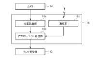
- the game machine main body 16 includes a position recognition unit 16a, an application processing unit 16b, and a communication unit 16c.
- the position recognition unit 16a and the application processing unit 16b are realized by executing a predetermined program in the game machine body 16 which is a computer game system.
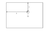
- an image taken by the camera 14 as shown in FIG. 3, for example, is supplied to the position recognition unit 16a.
- the position recognizing unit 16a extracts a region where the light emitter 20 is projected in the supplied image as shown in FIG. 4, and acquires the coordinates (X, Y) of the center position of the light emitter 20 in the image.
- the area of the region where the light emitter 20 is projected is calculated, and the distance between the camera 14 and the light emitter 20 is determined from the area.
- a relational expression between the area of the region and the distance to the light emitter 20 may be stored, and the distance may be determined according to this relational expression.
- the center position coordinates (X, Y) of the light emitter 20 and the distance between the camera 14 and the light emitter 20 in the captured image thus obtained are supplied to the application processing unit 16b.
- the application processing unit 16b uses these pieces of information, for example, to move the position of the cursor displayed on the screen of the television receiver 12, or to move the position of an object arranged in the virtual game space.
- the operation device 18 is also provided with conventional operation members such as buttons, and the operation content of these members is transmitted to the game machine main body 16 by wireless communication means.
- the game machine main body 16 includes a communication unit 16c for performing wireless communication with the operation device 18, and the application processing unit 16b also uses various operation contents received by the communication unit 16c to execute various applications such as games. Take control.
- the application processing unit 16b generates a display image according to application processing, and this display image is displayed by the television receiver 12.
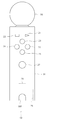
- the operation device 18 has a substantially cylindrical main body 31 extending from one end to the other end, and a light emitter 20 is provided on one end side.
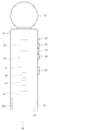
- the illuminant 20 is composed mainly of a light-diffusing resin having a substantially spherical shell shape and a light-emitting element that emits light to the resin.
- a connection (linkage) structure including a connection connector 28 for performing data communication with another additional operation module is provided on the other end side of the main body 31.
- this connection structure includes an accommodation recess 29 provided on the other end surface of the main body 31 and a female connection connector 28 provided at the center of the bottom surface of the accommodation recess 29.
- the accommodating recess 29 is formed in substantially the same shape as that of the other additional operation module so as to accommodate a part of the other additional operation module, and two engaging pieces ( Engagement portions 30f and 30b that are notches that engage with the engaged portion) are provided.
- the engaging portions 30 f and 30 b are provided on the front side and the back side of the main body 31.
- Buttons 21 to 27 are provided on the surface of the main body 31, and as described above, information on whether or not these buttons 21 to 27 are pressed is transmitted to the game machine main body 16 by wireless communication means.
- a control unit 32 As shown in FIG. 6, a control unit 32, a vibration motor 33, an acceleration sensor 34, a gyro sensor 35, a geomagnetic sensor 36, and a connection connector 28 are provided inside the main body 31.
- the control unit 32 is configured around a known CPU and wireless data communication means, and the detection contents of the acceleration sensor 34, the gyro sensor 35, and the geomagnetic sensor 36 are input to the control unit 32.
- the acceleration sensor 34 detects, for example, each acceleration (including gravitational acceleration) in the extending direction (axial direction (first axis)), front direction (second axis), and left-right direction (third axis) of the main body 31.
- the gyro sensor 35 is a three-axis gyro sensor that detects the rotation speed of the main body 31 around the first to third axes.
- the geomagnetic sensor 36 is means for detecting the direction of geomagnetism.
- the control unit 32 transmits the detection contents of these sensors to the game machine body 16, and the game machine body 16 determines the movement, posture, and position of the operation device 18 based on the detection contents of these sensors.
- the control unit 32 supplies driving power to the vibration motor 33, and starts or stops the operation of the vibration motor 33 according to a control signal transmitted from the game machine body 16 by radio or autonomously.
- the control unit 32 also supplies driving power for the light emitter 20.
- the controller 32 starts light emission by the light emitter 20 in accordance with a control signal transmitted wirelessly from the game machine body 16 or autonomously. Or stop it. Further, when the light emitter 20 is configured to emit light of any color as described later, the control unit 32 also controls the light emission color by the light emitter 20. A connection connector 28 is also connected to the control unit 32, and the operation content of the additional operation module is input through the connection connector 28. This operation content is also wirelessly transmitted to the game machine body 16. At this time, identification information for identifying the type of the additional operation module is stored in the additional operation module, and the identification information is read by the control unit 32. This identification information is also wirelessly transmitted to the game machine body 16. With the above configuration, the game machine body 16 can determine which type of additional operation module is connected to the operation device 18 and what operation has been performed on the additional operation module.
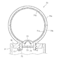
- FIG. 8 is an enlarged longitudinal sectional view of the light emitter 20.
- the light emitter 20 is composed of a spherical shell-shaped portion having a two-layer structure of an inner shell and an outer shell, and a light emitting element 73 provided adjacent to the spherical shell portion.
- the outer shell of the spherical shell portion is located on the distal end side of the operation device 18, and is located on the distal end side outer shell portion 70 a formed in a hemispherical shell shape that opens to the proximal end side, and on the proximal end side of the operation device 18.
- a base end side outer shell portion 70b formed in a hemispherical shell shape opened to the tip end side.
- a circular hole is formed in the bottom of the base-end-side outer shell portion 70b, and an attachment mechanism 75 that is a cylindrical wall that rises toward the main body 31 is provided around the hole.
- a screw groove is formed on the outer peripheral surface of the attachment mechanism 75.
- An opening is formed in the upper surface of the main body 31, and this opening is closed by a support base 76.
- An opening is formed in the center of the support base 76, and a mounted mechanism 77 that is a cylindrical wall that rises toward the inside of the main body 31 is provided around the opening.
- a screw groove is formed on the inner peripheral surface of the attachment mechanism 77, and the screw groove formed on the outer peripheral surface of the attachment mechanism 75 is screwed into this screw groove.
- the light emitter 20 is attached to the upper surface of the main body 31.
- a circuit board 74 on which the light emitting element 73 is mounted is attached inside the attachment mechanism 75.
- the light emitting element 73 is configured by an LED, for example.
- the light emitting element 73 emits light from a circular hole formed at the bottom of the base end side outer shell portion 70b toward the center of the spherical shell.
- the light emitting element 73 may include a plurality of LEDs that emit different colors. In this case, the light emission color is controlled by the control unit 32 together with the light emission timing.
- the inner shell is located on the distal end side of the operation device 18, and is located on the distal end side inner shell portion 71a formed in a hemispherical shell shape that opens to the proximal end side, and on the proximal end side of the operation device 18, and the distal end A proximal end inner shell portion 71b formed in a hemispherical shell shape that opens to the side.
- the outer diameter of the inner shell and the inner diameter of the outer shell are substantially the same, and both are in close contact.
- the proximal inner shell 71b is formed with a light receiving portion 72 that is a recess formed in the bottom of the outer surface.
- the light emitting element 73 faces the light receiving portion 72, so that the light emitted from the light emitting element 73 efficiently enters the inner shell.
- the distal inner shell 71a and the proximal inner shell 71b constituting the inner shell are both formed of a resin material having a light diffusion function.
- a resin material a material in which innumerable minute resin pieces, which are formed of a resin such as polycarbonate, which reflects light in a transparent resin such as polycarbonate, is encapsulated is used.
- the distal end side outer shell portion 70a and the proximal end side outer shell portion 70b constituting the outer shell are both made of a resin material having an achromatic color or a chromatic color and having translucency.
- this resin material for example, polycarbonate or the like is used.
- a dark gray material having translucency is used as the resin material of the outer shell.
- the outer surface of the outer shell is mirror-finished and coated with a low reflection film.
- the light emitted from the light emitting element 73 enters the inner shell at the light receiving portion 72, the incident light diffuses inside the inner shell, and light is emitted radially from the outer surface of the inner shell. This light is attenuated slightly in the outer shell and then emitted radially outward.
- the entire surface of the spherical light emitter 20 can be caused to emit light by the light emitting element 73 disposed on the upper surface side of the main body 31.
- the light emitter 20 since it has a two-layer structure consisting of an inner shell and an outer shell, and each shell has the above-described material structure, when the light emitter 20 is photographed by the camera 14, the light emitter 20 in the photographed image is displayed. A colored and translucent outer shell is clearly shown at the edge of the region, so that the size of the region where the light emitter 20 is projected can be recognized correctly.
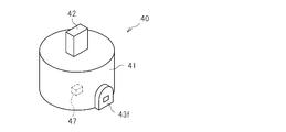
- FIG. 9 is a perspective view showing the first additional operation module from the front direction.
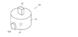
- FIG. 10 is a perspective view showing the device from the back side.
- FIG. 11 is a view showing a state in which the device is attached to the main body 31 in the forward direction
- FIG. 12 is a view showing a state in which the device is attached in the reverse direction.
- the first additional operation module 40 has a built-in microphone, and the player P inputs sound.
- the first additional operation module 40 includes a substantially cylindrical portion 41 to be accommodated, and an engagement portion 43f that rises in the front direction is provided at the lower end on the front side of the portion 41 to be received, and the rear side on the rear side.
- An engaged portion 43b is provided that rises to the top.
- the engaged portion 43f is formed with a small hole for taking the sound of the player P inside.
- the outer diameter of the accommodated portion 41 substantially matches the inner diameter of the accommodating recess 29 of the main body 31, and the accommodated portion 71 is accommodated in the accommodating recess 29.
- the engaged portions 43f and 43b engage with the engaging portions 30f and 30b, respectively.
- a connection connector 42 is attached to the upper surface of the accommodated portion 41, and this connection connector 42 is inserted into the connection connector 28 on the main body 31 side.
- the engaged parts 43f and 43b have the same outer shape, the engaging parts 30f and 30b also have the same outer shape, and the engaged parts and the engaging parts have corresponding shapes. Yes.
- connection connectors 28 and 42 can be electrically connected to each other even in the reverse direction. Therefore, as shown in FIG. 11, the engaged portion 43f engages with the engaging portion 30f provided on the front side of the main body 31, and the engaged portion 43b is connected to the main body as shown in FIG.
- the first additional operation module 40 can be attached to the main body 31 in both the reverse attachment state in which the engagement portion 30f provided on the front side of 31 is engaged.
- the first additional operation module 40 includes an acceleration sensor 47, and the detection content of the acceleration sensor 47 is transmitted to the control unit 32 and further transmitted to the game machine body 16.
- the game machine main body 16 also receives the detection contents of the acceleration sensor 34 of the main body 31, and by comparing these detection contents, it can be determined whether the first additional operation module is in the forward attachment state or the reverse attachment state. Judgment can be made. With the configuration described above, various usage methods of the operation device 18 can be realized.
- FIG. 13 shows a second additional operation module which is another type of additional operation module.
- FIG. 14 shows a state in which the second additional operation module is attached to the main body 31 in the forward direction.
- the second additional operation module 50 includes a cylindrical portion 51 to be received in the receiving recess 29, a connection connector 52 attached to the upper surface thereof, and a receiving portion 51 that is coaxially continuous with the lower surface of the receiving portion 51.
- the extension portion 54 has a cylindrical shape with a larger diameter than that of the extension portion 54.
- the accommodated portion 51 is provided with an engaged portion 53 that engages with the engaging portions 30f and 30b.
- An operation member 55 for inputting a direction is attached to the front surface of the extension portion 54.
- the second additional operation module 50 can also be attached to the base end portion of the main body 31 instead of the first additional operation module 40 as shown in FIG. Further, similar to the first additional operation module 40, forward mounting and reverse mounting are possible with respect to the main body 31. Also in this case, the game machine main body 16 compares the detection content of the acceleration sensor 34 of the main body 31 with the detection content of the acceleration sensor 57 built in the second additional operation module 50, so that the second addition It can be determined whether the operation module 50 is in the forward mounting state or the reverse mounting state. In this way, it is possible to attach an arbitrary one of a plurality of types of additional operation modules to the main body 31, which is compared with a case where an operation member of a type not normally used is integrated with the main body 31 in advance. Thus, the weight of the operation device 18 can be reduced. Thereby, the player P can operate the operation device 18 lightly.
- operation members in the additional operation module are provided.
- a rotating mechanism may be provided so that the part rotates. That is, as in the third additional operation module 60 shown in FIGS. 15 and 16, the accommodated portion 61 and the extension portion 64 having a larger diameter than that are integrally formed, and the connection connector 62 is connected to the accommodated portion 61. And an engaged portion 63, and a separate extension portion 66 is disposed on the lower surface side of the extension portion 64, and both the extension portions 64 and 66 are relatively moved by a rotating shaft extending in the extending direction of the main body 31. You may comprise so that rotation is possible. Even in this case, the operation member 65 provided in the extension portion 66 can be rotated with respect to the main body 31.
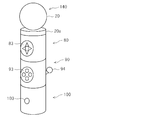
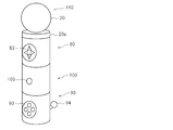
- FIG. 17 is an external perspective view of the operation device according to the second embodiment
- FIG. 18 is a perspective view showing the light emitting module from the front direction
- FIG. 19 is a perspective view showing the main body module from the front direction
- FIG. FIG. 21 is a perspective view showing the first additional operation module from the front direction
- FIG. 21 is a perspective view showing the second additional operation module from the front direction.
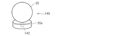
- the light emitting module 140, the main body module 80, the first additional operation module 90, and the second additional operation module 100 are connected in series in this order with the front surfaces of the modules aligned. . As shown in FIG.
- the light emitter 20 is attached to the upper surface of a short cylindrical main body 20a, and a connection connector (female connector) 142 is provided in the center of the lower surface.
- the main body of the main body module 80 has a columnar shape with the same diameter as the main body 20a of the light emitting module 140, and an operation member 83 for inputting direction information is arranged on the front surface.
- a connection connector (male connector) 81 is provided at the center of the upper surface of the main body, and a connection connector (female connector) 82 is provided at the center of the lower surface. As shown in FIG.
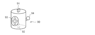
- the main body of the first additional operation module 90 has a cylindrical shape with the same diameter as the main body of the main body module 80, and an operation member 93 made up of a plurality of buttons is arranged on the front surface. . Further, a stick-like operation member 94 for transmitting a signal corresponding to the tilt direction to the game machine main body 16 by tilting on the back is arranged.
- a connection connector (male connector) 91 is provided at the center of the upper surface of the main body, and a connection connector (female connector) 92 is provided at the center of the lower surface. Furthermore, as shown in FIG.
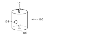
- the main body of the second additional operation module 100 has a columnar shape with the same diameter as the main body of the main body module 80, and an operation member 103 made up of a single button is arranged on the front.
- a connection connector (male connector) 101 is provided at the center of the upper surface of the main body, and a connection connector (female connector) 102 is provided at the center of the lower surface.
- connection connector 81 of the main body module 80 is inserted into the connection connector 142 of the light emitting module 140 so that the front surfaces of both modules are aligned, and the connection connector 91 of the first additional operation module 90 is connected to the main body module 80.
- the connector 82 By inserting the connector 82 into the connector 82 so that the front surfaces of both modules are aligned, and further inserting the connection connector 101 of the second additional operation module 100 into the connection connector 92 of the first additional operation module 90 so that the front surfaces of both modules are aligned.
- connection connectors 81, 91, 101 have the same shape, and the connection connectors 82, 92, 102, 142 also have the same shape. For this reason, the connection order of each module can be changed arbitrarily. For example, in the example illustrated in FIG. 22, the connection order of the first additional operation module 90 and the second additional operation module 100 is switched.
- connection connectors 81, 82, 91, 92, 101, 102, 142 may be configured such that the front surfaces of the two modules to be connected are aligned or the front surface of one module is aligned with the back surface of the other module.
- the electrical connection is possible. For this reason, the direction which connects each module with respect to another module is free.
- the first additional operation module 90 is connected to the main body module 80 so that the back surface thereof is located on the same side as the front surface of the main body module 80.
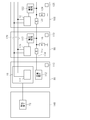
- FIG. 24 is a diagram showing a circuit configuration of each module of the operation device.
- a serial bus 120 is formed by a method such as I2C (Inter-Integrated Circuit) by connecting each connection connector.
- the main body module 80 is provided with a control unit 110 mainly composed of a CPU and a wireless communication module.
- the control unit 110 includes a master communication unit 111 that controls data communication via the serial bus 120.
- the main body module 80 includes an acceleration sensor 113, and the detection content of the acceleration sensor 113 is input to the control unit 110.
- a reference voltage generation unit 112 which is a generation source of the reference voltage is provided, and the reference voltage is applied to other modules connected by the connection connector 82.
- the control unit 110 controls the light emission timing and the light emission color in the light emitting element 73 independently or in accordance with a control signal transmitted from the game machine body 16 via the wireless communication module.
- a signal line extending from the connection connector 91 to the connection connector 92 is provided as a partial section of the serial bus 120.
- the slave communication unit 118 is connected to this section, and data indicating the operation content in the operation members 93 and 94 is transmitted to the master communication unit 111 by the slave communication unit 118.
- identification information indicating the type of the first additional operation module 90 stored in a memory (not shown) is also transmitted to the master communication unit 111.
- the first additional operation module 90 also includes an acceleration sensor 119, and the detected content is transmitted to the master communication unit 111 by the slave communication unit 118.
- the first additional transmission module 90 is further provided with a voltage signal line 114 extending from the connection connector 91 to the connection connector 92, and a resistor 115 is inserted in the middle of the voltage signal line 114.
- One end of the resistor 116 whose other end is grounded is connected to the connection connector 92 side with respect to the resistor 115.
- the voltage at the one end of the resistor 116 is detected by the voltmeter 117, and the content is also transmitted to the master communication unit 111 by the slave communication unit 118.
- the second additional operation module 100 has the same configuration as the first additional operation module 90, and a signal line extending between the connection connector 101 and the connection connector 102 is provided as a partial section of the serial bus 120.
- the slave communication unit 121 is connected to this section, and data indicating the operation content on the operation member 103 is transmitted to the master communication unit 111 by the slave communication unit 121.
- identification information indicating the type of the second additional operation module 100 stored in a memory (not shown) is also transmitted to the master communication unit 111.
- the second additional operation module 100 also includes an acceleration sensor 125, and the detected content is transmitted to the master communication unit 111 by the slave communication unit 121.
- the second additional operation module 100 is further provided with a voltage signal line extending from the connection connector 101 to the connection connector 102, a resistor 123 is inserted in the middle of the voltage signal line, and One end of the resistor 124 whose other end is grounded is connected to the connection connector 102 side with respect to the resistor 123.
- the voltage at the one end of the resistor 124 is detected by the voltmeter 122, and the content is also transmitted to the master communication unit 111 by the slave communication unit 121.
- the information collected in the control unit 110 is transmitted to the game machine body 16 by the wireless communication module.
- the game machine body 16 compares the voltage values transmitted from the modules and determines the connection order of the modules. That is, considering the voltage value detected by the order from the main module 80 gradually decreasing, the connection order of the modules is determined. Further, by comparing the detection contents of the acceleration sensors 113, 119, and 125 transmitted from the modules, the direction in which the modules are connected is determined. Then, the processing content of the application is changed according to the determination content.
- connection order In addition, the table which recorded the connection order and voltage range in the 1st and 2nd additional operation modules 90 and 100 is hold
- the operation device is constituted by a plurality of modules, the operation member is provided on the side surface of each module, and the connection mode of each module is flexible, the type of application executed on the game machine main body 16 is determined.
- the operation device can be freely deformed according to the preference of the player P.
- the processing content of an application can be changed according to a connection aspect.
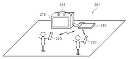
- FIG. 25 is a schematic diagram of an information processing system 201 according to the third embodiment.
- the information processing system 201 includes an information processing apparatus 210 and a plurality of operation devices 220 each having a light emitting unit.
- the information processing device 210 includes an imaging unit 214 and is connected to the display device 215.
- each operation device 220 can be connected to the information processing apparatus 210 via a wireless communication interface.
- a user of the information processing system 201 holds the operation device 220 and manually operates buttons and the like provided on the operation device 220. In response to this, the user's operation content is transmitted to the information processing apparatus 210 via the wireless communication interface.
- the information processing apparatus 210 captures light emitted from the light emitting unit of each operation device 220 by the image capturing unit 214 and specifies the position of each operation device 220 in the real space using the captured image. Accordingly, each user can perform an operation input to the information processing apparatus 210 not only by operating a button or the like provided on the operation device 220 but also by moving the operation device 220 itself.
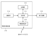
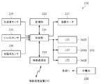
- the information processing apparatus 210 is, for example, a home game machine or a personal computer, and includes a control unit 211, a storage unit 212, a wireless communication unit 213, and an imaging unit 214, as shown in FIG. Consists of.
- the information processing apparatus 210 is connected to the display device 215.
- the control unit 211 is, for example, a microprocessor or the like, and executes various types of information processing according to programs stored in the storage unit 212. A specific example of processing executed by the control unit 211 in the present embodiment will be described later.
- the storage unit 212 includes a memory element such as a RAM or a ROM, and stores programs executed by the control unit 211 and various data. It also operates as a work memory for the control unit 211.
- the wireless communication unit 213 is a wireless communication interface, and transmits and receives information to and from the operation device 220 through wireless communication without using a transmission line.
- the wireless communication unit 213 may be a wireless communication interface based on, for example, the Bluetooth (registered trademark) standard.
- the wireless communication unit 213 can execute data transmission / reception with a plurality of operation devices 220. That is, the wireless communication unit 213 establishes a communication connection with each operation device 220, performs a time division multiplex communication, or performs communication in different frequency bands. Communicate between the two.
- the information processing apparatus 210 assigns a logical number for identifying the operation device 220 to each operation device 220.
- the information processing apparatus 210 identifies each operation device 220 by this logical number and exchanges data.
- the imaging unit 214 is a camera device and captures a peripheral image. Specifically, for example, the imaging unit 214 is installed at a position where the user who views the screen of the display device 215 such as the upper part of the display device 215 can capture an image, and captures a color image.
- the imaging unit 214 functions as a detection unit that detects light emitted from the light emitting unit of the operation device 220. That is, when the imaging unit 214 images the operation device 220 held by the user, the information processing apparatus 210 detects light emitted from the light emitting unit of the operation device 220.
- the display device 215 is a home television receiver or the like, for example, and displays various types of information to be presented to the user on the screen according to the video signal output from the information processing device 210.
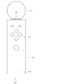
- FIG. 27A and 27B are diagrams showing an example of the appearance of the operation device 220.
- FIG. 27A is a front view of the operation device 220
- FIG. 27B is a bottom view.
- the operation device 220 has a shape in which a spherical light emitting unit 222 is attached to one end of a cylindrical main body 221, and a plurality of buttons 223 are provided on the surface of the main body 221. Is provided. The user holds the main body 221 and performs an operation input for pressing each button 223 with a finger.
- a USB connector 224 corresponding to the USB (Universal Serial Bus) standard is provided on the bottom surface of the main body 221.
- the operation device 220 may be provided with an expansion connector that can connect various devices.
- FIG. 28 is a configuration block diagram showing an example of the internal configuration of the operation device 220.
- the main unit 221 includes a control unit 231, a storage unit 232, a wireless communication unit 233, an acceleration sensor 234, a gyro sensor 235, a geomagnetic sensor 236, a vibration motor 237, and a rechargeable battery 238. It is configured to include.
- the light emitting unit 222 includes a plurality of LEDs 240.
- the control unit 231 is a microprocessor or the like, acquires a signal indicating the content of a user's operation input to the button 223, a signal indicating a detection result of each sensor described later, and the like, and transmits the acquired signal to the wireless communication unit 233. Output.
- light emission control of each LED 240 and drive control of the vibration motor 237 are performed according to a control signal periodically received from the information processing apparatus 210 via the wireless communication unit 233.
- the storage unit 232 includes a memory element such as a RAM or a ROM, and stores programs and data necessary for the control process of the control unit 231.
- the wireless communication unit 233 is a wireless communication interface of the same type as the wireless communication unit 213 of the information processing apparatus 210, and transmits and receives information to and from the wireless communication unit 213 by wireless communication. Specifically, the wireless communication unit 233 transmits and receives data to and from the information processing device 210 periodically (for example, every 11.25 ms) in response to an inquiry from the information processing device 210.
- the acceleration sensor 234, the gyro sensor 235, and the geomagnetic sensor 236 function as detection means for detecting the orientation (posture) and movement of the operation device 220. Specifically, in the present embodiment, it is assumed that three reference axes that are orthogonal to the operation device 220 are set.
- the acceleration sensor 234 detects acceleration generated in the directions of the three reference axes. By detecting the direction of the gravitational acceleration generated in the operation device 220 by the acceleration sensor 234, the inclination of the operation device 220 with respect to the vertical direction can be specified. Further, the moving direction and moving speed when the operating device 220 moves can be specified by the acceleration generated by the movement of the operating device 220.
- the gyro sensor 235 detects the angular velocity of rotation about each of the three reference axes similar to the acceleration sensor 234. By integrating the respective speeds detected by the gyro sensor 235 per unit time, the rotation amount of the operation device 220 with each reference axis as the rotation center can be calculated.
- the geomagnetic sensor 236 detects the magnitude of the magnetic field along the direction of each of the three reference axes. When this geomagnetic sensor 236 detects geomagnetism, it is possible to specify which direction the operation device 220 is facing.
- the vibration motor 237 vibrates the operation device 220 by being driven according to a control signal from the control unit 231. As a result, vibration can be transmitted to the user's hand holding the operation device 220 to enhance the presence in a game or the like. Note that a plurality of vibration motors 237 may be disposed inside the operation device 220.
- the rechargeable battery 238 is a secondary battery such as a lithium ion battery, for example, accumulates electric power supplied from the outside, and supplies the accumulated electric power to each unit in the operation device 220. In other words, each unit of the operation device 220 operates with electric power supplied from the rechargeable battery 238.
- the remaining amount of power charged in the rechargeable battery 238 decreases, for example, sufficient power for operating the wireless communication unit 233 cannot be secured, and communication with the information processing device 210 via the wireless communication unit 233 is not possible. It may not be possible to continue.
- the rechargeable battery 238 is charged with electric power supplied from the USB host device via the USB bus.
- the USB host device may be the information processing apparatus 210 having a USB interface.
- the operation device 220 is charged via the USB bus here, the present invention is not limited to this, and the rechargeable battery 238 may be charged by supplying power from, for example, a household AC power source.
- the plurality of LEDs 240 each emit light under the control of the control unit 231.
- three LEDs 240, an LED 240 ⁇ / b> R that emits red light, an LED 240 ⁇ / b> G that emits green light, and an LED 240 ⁇ / b> B that emits blue light are arranged side by side inside the light emitting unit 222.
- the light is emitted with the intensity of light corresponding to the control signal.
- each LED 240 can change its brightness with a 16-bit gradation
- each of the LED 240R, LED 240G, and LED 240B emits light with a brightness according to the brightness value specified by the control unit 231.
- the light emitting unit 222 can emit light in various colors.
- the information processing apparatus 210 functionally includes an application execution unit 251, a device state management unit 252, a light emission control unit 253, and a device position specifying unit 254 as illustrated in FIG. Consists of. These functions can be realized by the control unit 211 executing a program stored in the storage unit 212. This program may be provided by being stored in various computer-readable information storage media such as an optical disk, or may be provided via a communication network such as the Internet.
- the application execution unit 251 executes various processes defined by an application program such as a game application. Specifically, the application execution unit 251 executes various processes according to user instruction operations input from the operation device 220, and outputs the execution results on a screen of the display device 215. .
- the application execution unit 251 may execute not only a user operation on the button 223 provided on the operation device 220 but also a process according to the position and orientation of the operation device 220 in the real space. Therefore, the application execution unit 251 acquires information indicating the position and orientation of the operation device 220 from the device position specifying unit 254 described later. Thereby, the application execution unit 251 can execute processing according to various movements that the user moves, shakes, or rotates the position of the operation device 220, for example.
- the application execution unit 251 may output a vibration instruction for vibrating the vibration motor 237 built in the operation device 220 according to the content of the process. The vibration instruction is transmitted to the operation device 220 via the wireless communication unit 213 and causes the vibration motor 237 inside the operation device 220 to vibrate.
- the device state management unit 252 manages the state of the operation device 220 connected to the information processing apparatus 210. Specifically, when there is a connection request for the operation device 220 via the wireless communication unit 213, the device state management unit 252 assigns a logical number (port number) to the operation device 220 that has made the connection request.
- the information processing apparatus 210 assigns different logical numbers to the respective operation devices 220 in the order in which connection requests are made. That is, the information (for example, network address) for specifying the operation device 220 that has requested connection on the wireless communication network is associated with an unassigned port number. By executing this port number assignment (port assignment), thereafter, the information processing apparatus 210 can identify each of the plurality of operation devices 220 connected at the same time by the port number. For example, the application execution unit 251 specifies from which operation device 220 of the plurality of operation devices 220 an operation input is performed and to which operation device 220 various control signals are transmitted by this port number. To do.
- the device state management unit 252 acquires information regarding the state of each connected operation device 220, and performs processing such as presenting the state of the operation device 220 to the user according to the acquired information. A specific example of such processing will be described later.
- the light emission control unit 253 controls light emission of the light emitting unit 222 in each connected operation device 220 using an instruction from the application execution unit 251 and information on the device state of the operation device 220 acquired by the device state management unit 252. To do. Specifically, when the plurality of operation devices 220 are connected for communication via the wireless communication unit 213, the light emission control unit 253 emits the light emission units 222 of the plurality of operation devices 220 in different emission colors. Thus, the emission color is controlled. In addition, the light emission mode of the light emitting unit 222 is changed according to the device state of the operation device 220 connected for communication.
- the light emission control unit 253 may change the light emission color of the light emitting unit 222 according to various conditions such as the execution status of the processing by the application execution unit 251. A specific example of the light emission control of the light emitting unit 222 by the light emission control unit 253 will be described later.
- the device position specifying unit 254 specifies the position of each operation device 220 using the image picked up by the image pickup unit 214. Specifically, the device position specifying unit 254 acquires captured image data captured by the imaging unit 214 every predetermined time. Then, image processing such as pattern matching processing is performed on the acquired captured image, and an image of light emitted from the light emitting unit 222 is extracted from the captured image. Further, the device position specifying unit 254 specifies the position of the operation device 220 within the visual field range of the imaging unit 214 based on the position of the extracted light image in the captured image. Further, the distance from the imaging unit 214 to the operation device 220 is specified based on the size of the extracted light image in the captured image. Thereby, the position of the operation device 220 with respect to the imaging unit 214 in the real space is specified.
- the operation device 220 moves outside the field of view of the imaging unit 214, the light emitting unit 222 is directed to the opposite side of the imaging unit 214, or by an obstacle or a user's hand The light from the light emitting unit 222 may be blocked, and the light emitting unit 222 may be temporarily undetectable. Therefore, in the present embodiment, the device position specifying unit 254 specifies the position of the operation device 220 using not only the captured image of the imaging unit 214 but also a signal indicating the detection result of the sensor transmitted from each operation device 220. .
- the position of the operation device 220 is specified with higher accuracy, the inclination of the operation device 220 is also specified, and the position of the operation device 220 is tracked even while the light image of the light emitting unit 222 cannot be detected from the captured image. can do.
- the device position specifying unit 254 starts from a predetermined reference position, periodically repeats the position specifying process of the operation device 220 using the light of the light emitting unit 222, and tracks the position of the operation device 220. Go. In parallel with this, the position of the operation device 220 is also tracked by calculating the movement direction and movement distance of the operation device 220 with respect to the reference position using output values of various sensors built in the operation device 220. At this time, in order to calculate the moving direction and moving distance of the operation device 220 from the output value of the sensor, the device position specifying unit 254 performs an operation using a predetermined coefficient on the output value of the sensor.
- the device position specifying unit 254 sets the predetermined coefficient so that the difference between the position of the operation device 220 specified by the light of the light emitting unit 222 and the position specified by the output value of the sensor is minimized. Make corrections.
- the sensor output value is calculated using the corrected coefficient, and the position of the operation device 220 is specified. In this way, by performing correction using the position information of the operation device 220 obtained while the light from the light emitting unit 222 can be detected, the sensor output value can be used relatively while the light cannot be detected.
- the position specification of the operation device 220 can be continued with high accuracy.
- the light emission control unit 253 controls the light emission colors of the operation devices 220 to be different from each other. Therefore, when there are a plurality of light images of the light emitting unit 222 in the image captured by the image capturing unit 214, which operation device 220 corresponds to the light image detected from the captured image by the color of each light. Can be identified.
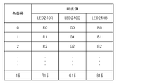
- the storage unit 232 of the operation device 220 stores a color management table.
- This color management table is a table in which a color number and brightness information of each LED 240 for causing the light emitting unit 222 to emit light with a color corresponding to the color number are associated with each other.
- FIG. 30 shows an example of the color management table.
- each lightness value Rn, Gn representing the lightness of the LEDs 240R, 240G and 240B for causing the light emitting unit 222 to emit light with a predetermined color
- each lightness value Rn, Gn, and Bn is, for example, a 16-bit numeric value.
- an instruction to change the light emission color is given to the operation device 220 together with information specifying the color number.
- Send to since the information processing apparatus 210 transmits / receives data to / from the operation device 220 by wireless communication every predetermined time, the light emission control unit 253 emits light from the operation device 220 at a timing for each predetermined time. Send instructions to change color.
- the control unit 231 of the operation device 220 reads the brightness value of each LED 240 associated with the designated color number from the color management table.
- the control unit 231 controls the brightness of each LED 240 according to the read brightness value, thereby causing the light emitting unit 222 to emit light with a color corresponding to the designated color number.
- the light emission control unit 253 emits light from the operation device 220 with any one of 16 colors such as blue, red, magenta, green,... Previously associated with 0 to 15 color numbers.
- the part 222 can emit light.
- the operation device 220 may store a plurality of color management tables. For example, a fixed color management table T1 written at the time of shipment of the operation device 220 from the factory is stored in the ROM, and a variable that can be rewritten by the user's selection or an instruction from the application execution unit 251 while the operation device 220 is operating in the RAM.
- the color management table T2 may be stored. In this case, the variable color management table T2 is read into the RAM with the same contents as the fixed color management table T1 in the initial state of the operation device 220.
- the light emission control unit 253 selects, for example, a new color that is not included in the fixed color management table T1 according to a user's instruction operation, and the lightness value of each LED for causing the light emitting unit 222 to emit light with the color. Is transmitted to the operation device 220 together with the designation of the color number.
- the control unit 231 of the operation device 220 updates the brightness value associated with the designated color number in the variable color management table T2 in accordance with the information transmitted from the information processing apparatus 210.
- the light emission control unit 253 can be designated as the light emission color of each operation device 220.
- the light emission control unit 253 may transmit an instruction to update the variable color management table T2 in the RAM to the operation device 220 in response to a request from the application execution unit 251.
- the information processing apparatus 210 causes the operation device 220 to store in advance the information on the color that the application execution unit 251 wants to emit light when the process is executed regardless of the color stored in the fixed color management table T1. It is possible to implement light emission control according to the processing content of the application execution unit 251 such as changing the emission color in conjunction with the progress of the processing of the application execution unit 251.
- the light emission control unit 253 changes information for specifying the color management table (here, fixed color) when changing the light emission color of the operation device 220.
- a light emission color change instruction is transmitted to the operation device 220 together with information specifying the management table T1 and the variable color management table T2) and information specifying the color number in the specified color management table.
- the light emission control unit 253 may instruct to change the light emission color by directly specifying the brightness value of each LED 240 instead of specifying the color number.
- the light emission control unit 253 transmits a light emission color change instruction to the operation device 220 together with information on lightness values indicating the lightness of the LEDs 240R, 240G, and 240B in response to an instruction from the application execution unit 251.
- the information processing apparatus 210 can cause the light emitting unit 222 of the operation device 220 to emit light in a color that is not included in the color management table in the operation device 220 in accordance with the processing content executed by the application execution unit 251. it can.
- a predetermined button 223 (such as a power button) is operated.
- the operation device 220 starts control for causing the light emitting unit 222 to emit light in a predetermined pattern. Specifically, a lightness value of a predetermined color number is read from the fixed color management table T1 in the ROM, and each LED is caused to emit light according to the read lightness value.
- the light emitting unit 222 emits light with a specific color, and the user establishes the wireless communication connection with the light emission color of the light emitting unit 222. You can know that it has not been completed.
- the operation device 220 may cause the light emitting unit 222 to blink with a predetermined color, or cause the light emitting unit 222 to emit light while sequentially changing a plurality of colors (for example, seven colors). In this way, it is possible to show the user that the connection is being established more clearly.
- the operation device 220 transmits a connection request to the information processing apparatus 210 in response to an instruction to start using the user.
- the device state management unit 252 assigns a port number to the operation device 220 as described above.
- the light emission control unit 253 that has received notification from the device state management unit 252 that the port number has been assigned to the new operation device 220 determines the light emission color of the newly connected operation device 220. To do.
- the light emission control unit 253 uses the color of the same color number as the assigned port number (that is, the color number 1 for the operation device 220 assigned to the first port) as the emission color of the operation device 220. decide. Then, the operation device 220 is instructed to change the emission color specifying the determined color number.
- the user can know that the establishment of the wireless communication connection is completed. Note that this color change may be executed seamlessly. That is, the light emission color of the light emitting unit 222 may be changed by gradually changing the brightness value of each LED 240 from the light emission color at the timing when establishment of the wireless communication connection is completed to the color instructed to be changed.
- the light emission control unit 253 determines a different color as the light emission color for each port number assigned to each operation device 220.
- the light emission control unit 253 is blue (color number 1) for the operation device 220 assigned to the first port, red (color number 2) for the second port, and magenta (color number 3) for the third port. Different colors are assigned in advance for each port number, such as green (color number 4) for the fourth port.
- the light emitting units 222 of the plurality of operation devices 220 emit light in different colors, and the user emits light in the emission color.
- Each operation device 220 can be identified. Thereby, the operation device 220 does not need to be separately provided with an indicator or the like for displaying the connected port number.
- the light emission control unit 253 may change the color determined according to the port number according to the user's instruction.
- the user operates the operation device 220 and gives an instruction to change the emission color from the menu screen.
- the light emission control unit 253 presents light emission color candidates on the screen of the display device 215.
- the presented light emission color candidates may be, for example, colors stored in the variable color management table T2 stored in the operation device 220 possessed by the instructing user.
- the light emission control unit 253 may exclude a color that has already been selected as the light emission color of the other operation device 220 from the colors to be presented.
- the information processing apparatus 210 stores a color instructed to emit light to each operation device 220 that is in communication connection.
- FIG. 31 shows an example of a device emission color correspondence table for managing the correspondence between the port number of each operation device 220 and the emission color of the operation device 220.
- a light emission instruction is given to the operation device 220 in a predetermined color for each port number.
- the light emission control unit 253 stores the instructed color in the device light emission color correspondence table in association with the port number. In the example of FIG. 31, it is assumed that the operation device 220 connected to the first port is instructed to emit light in blue for the operation device 220 connected to the second port.
- the light emission control unit 253 displays each color stored in the variable color management table T2 in the operation device 220. Get information about. Then, it is confirmed whether there is any color designated as the emission color of the other operation device 220 among the acquired colors, and the remaining colors excluding such colors are presented to the user as emission color selection candidates.
- the red color that has already been instructed to the operation device 220 of the second port is excluded.
- FIG. 32 shows an example of a display screen for such a selection candidate of the luminescent color.
- the light emission control unit 253 designates the color number of the selected color and instructs the operation device 220 to change the light emission color. According to such a configuration, the user can change the light emission color of the light emitting unit 222 to his / her favorite color regardless of the port number to which the operation device 220 possessed by the user is assigned.
- the light emission colors of the other operation devices 220 are not presented as selection candidates, even if each user freely changes the light emission color of his operation device 220, the light emission of each operation device 220 connected by wireless communication is possible. The colors can be controlled to be different from each other.
- the device position specifying unit 254 distinguishes each of the plurality of operation devices 220 from each other and executes the position specifying process. it can.
- presentation of the selection candidate of the luminescent color may be realized by a method other than displaying on the screen of the display device 215.
- the light emission control unit 253 may cause the light emission unit 222 to emit light by sequentially switching a plurality of light emission color selection candidates each time the user operates the button 223 for instructing color switching. In this way, the user can change the emission color by repeating the operation of the button 223 until the light emitting unit 222 emits light in the color desired by the user.
- the light emission control unit 253 skips the light emission color of the other operation device 220 and switches the light emission color, so that the light emission color selection candidates presented to the user are already used by the other operation device 220. Spent colors can be excluded.
- the light emission control unit 253 not only uses the same color as the color used in the other operation device 220 but also a color close to the used color (for example, a color whose difference in hue value is less than a predetermined threshold). You may exclude from the selection candidate shown to a user.
- the user may be required to change the port number assigned to the operation device 220.
- the light emission control unit 253 causes the light emitting unit 222 of the operation device 220 to emit light in a color associated with the port number before the change, the color associated with the port number after the change.
- the emission color of the light emitting unit 222 may be changed.
- the emission control unit 253 does not change the emission color of the operation device 220 and the user selects the emission color. It is good also as maintaining.
- the device emission color correspondence table illustrated in FIG. 31 only the port number to which the operation device 220 has been assigned and the emission color corresponding to the newly assigned port number are changed. It becomes.
- the control unit 231 of the operation device 220 establishes the communication connection with the emission color of the light emitting unit 222.
- Control for changing to a predetermined color indicating a state of not being performed may be executed. If the predetermined color in this case is a color different from the light emission color determined according to the port number, the user can know the disconnection of the communication connection by the light emission of the light emitting unit 222.
- the information processing apparatus 210 sets the port number corresponding to the emission color requested by the operation device 220 side. It may be assigned to the operation device 220.
- the device state management unit 252 associates the operation device 220 that has made the connection request with the specified light emission color in advance. Assigned port number.
- the operation device 220 includes, for example, a selection switch for selecting a color on the surface, and performs a connection request to the information processing apparatus 210 by specifying the color selected by the user operating the selection switch.
- the operation device 220 may make a connection request by designating the emission color at the previous operation.
- the operation device 220 is configured to be able to connect an expansion device (such as a memory card) in which information (color number or the like) specifying the emission color is stored via the USB connector 224 or other expansion connector.
- the connection request may be made by designating a color specified by information stored in the extension device. In this way, the user does not change the color determined according to the port number assigned at the time of connection, but instead owns the user's favorite color or the color he / she always uses from the beginning of the connection.
- the light emitting unit 222 of the operation device 220 can emit light.
- the designated color is notified to the light emission control unit 253, and the light emission control unit 253 manages the light emission color of each operation device 220 to be connected.
- the information processing apparatus 210 rejects the connection request for the operation device 220.
- an error message is displayed, and control such as allowing the user to select another color by the same method as in the example of FIG. 32 described above is performed, and the light emission colors of the plurality of operation devices 220 are different from each other. Can be.
- the light emission control unit 253 performs light emission control of the light emitting unit 222 using information on the device state of the operation device 220 acquired by the device state management unit 252. Specifically, for example, the light emission control unit 253 may change the light emission mode of the light emitting unit 222 according to the charge state of the rechargeable battery 238 built in the operation device 220. In this case, the device state management unit 252 periodically acquires numerical information indicating the remaining charge amount of the rechargeable battery 238 from the operation device 220. When it is determined that the numerical information falls below a predetermined threshold and the remaining charge of the rechargeable battery 238 has decreased, the device state management unit 252 notifies the light emission control unit 253 of the determination result.
- the light emission control unit 253 instructs the operation device 220 to cause the light emitting unit 222 to emit light with a predetermined color indicating that the remaining charge amount is low. Thereby, even if the operation device 220 does not have an indicator or the like indicating the charge state of the rechargeable battery 238, the user can know the charge state of the operation device 220.
- the light emission control unit 253 emits a light color that is instructed according to the assigned port number or user selection as described above, and a light emission color that warns the remaining charge amount. And may be executed by alternately switching between and.
- the light emission control unit 253 does not always perform light emission control that warns the state when the remaining charge level is low, but causes the light emission unit 222 to emit light with a light emission color indicating the remaining charge level at a predetermined timing. Also good. For example, when the user performs an operation on a predetermined button 23 for displaying the remaining charge amount, the light emission control unit 253 displays a color corresponding to the remaining charge amount at that time (green if the state is close to full charge, less than half The light emitting unit 222 is caused to emit light in yellow when it becomes, or red if it is close to the sky.
- the light emission control unit 253 when a user instruction to display the remaining charge amount, does not change the light emission color, lights up when fully charged, flashes when less than half, and is nearly empty If so, the light emission mode may be changed such as turning off. In this way, the user normally checks the state of charge by changing the light emission mode of the light emitting unit 222 as necessary while causing the light emitting unit 222 to emit light with the connected port number or the color selected by the user. be able to. Further, the light emission control unit 253 may present the state of charge to the user by changing the brightness of the light emission color according to the remaining charge without changing the hue of the light emission color.
- the operation device 220 may change the light emission mode of the light emitting unit 222 according to the state of charge by the method described above independently without depending on the control of the light emission control unit 253 in some cases.
- the operation device 220 can change the light emission mode of the light emitting unit 222 according to the remaining charge amount, whereby the user can know the remaining charge amount.
- it is possible to control the light emission mode according to the remaining charge amount.
- the light emission control unit 253 may execute the light emission control of the operation device 220 according to the device state of various operation devices 220 other than the charged state.
- the operation device 220 detects the vibration mode generated by the driving of the vibration motor 237 by the output of each sensor such as the acceleration sensor 234, and the light emission control unit 253 determines whether the light emission unit 222 is in accordance with the vibration mode.
- the emission color may be changed.
- the operation device 220 is placed on a tabletop or the like, the user is lightly grasping the main body 221 with a hand, or is strongly grasped.
- the mode of vibration changes depending on the state.
- the light emission control unit 253 can execute control such as changing the light emission color to a predetermined color when the user grips the main body 221 with his / her hand while driving the vibration motor 237, for example. .
- the light emission control part 253 may change the light emission color according to the operation condition with respect to the button 223 by the user.
- the operation device 220 includes, for example, a pressure-sensitive sensor that detects whether or not the user is holding the main body unit 221, and the light emission control unit 253 includes such a sensor. The emission color may be changed according to the detection result.
- the light emission control unit 253 changes the light emission mode of the light emitting unit 222 according to various conditions such as whether the user is holding the operation device 220 or what button operation is being performed. Can be made.
- the operation timing and the like can be indicated to the user. It can be presented in an easy-to-understand manner. For example, when various operation inputs are performed by swinging or tilting the operation device 220 while pressing a specific button 223, the light emission color of the light emitting unit 222 is changed in response to the specific button 223 being pressed. By this, it is easily communicated to other users other than the user who operates the button 223 while holding the operation device 220 what button operation the user who owns the operation device 220 is performing. be able to.
- the light emission control unit 253 may change the light emission color according to an expansion device connected to the operation device 220.
- the operation device 220 may be connectable to an expansion device (such as a memory card) in which identification information for identifying the user is stored via the USB connector 224 or another expansion connector.
- the user identification information stored in the extension device is transmitted from the operation device 220 to the information processing apparatus 210, and the light emission control unit 253 emits light in a color stored in advance in association with the transmitted user identification information.
- the unit 222 is instructed to emit light.
- the operation device 220 can be made to emit light with a color set in advance.
- control for changing the light emission color of the light emission unit 222 to the color instructed by the application execution unit 251 may be executed.
- a plurality of users each carry the operation device 220 and perform an operation input, but here, an example in which a plurality of users share one operation device 220 will be described.
- the application execution unit 251 executes a multi-user participation type game application in which a game progresses by a plurality of users performing an instruction operation in order. In this case, each user carries out an instruction operation with the operation device 220 in turn.
- the light emission control unit 253 performs control to cause the light emission unit 222 to emit light in a color associated with the next user each time the application execution unit 251 advances the game process after the instruction operation of each user is finished.
- each user selects a color corresponding to himself / herself from a plurality of selection candidates before starting the game.
- the light emission control unit 253 presents each user with a light emission color selection screen illustrated in FIG. 32 in order, and causes each user to select a light emission color in advance. For example, if two players, player 1 and player 2, have participated in the game and red and blue have been selected in advance, respectively, when it is time for player 1 to perform an instruction operation, light emission control unit 253 executes application execution.
- an instruction to cause the light emitting unit 222 to emit red light is given to the operation device 220.
- the light emitting unit 222 emits red light
- the player 1 knows that he should operate the operation device 220.
- the light emission control unit 253 causes the light emitting unit 222 to emit light in blue. As a result, it is understood that the player 2 should perform an operation next time.
- control for changing the light emission color of the light emission unit 222 may be executed according to the surrounding environment of the information processing apparatus 210.
- the light emission control unit 253 changes the light emission luminance of the light emitting unit 222 according to the surrounding environment of the information processing apparatus 210 specified by the captured image of the imaging unit 214. That is, when the brightness of the entire captured image is low (the room is dark), the light emission luminance of the light emitting unit 222 is lowered.
- the power consumption by light emission of the light emission part 222 can be suppressed, without reducing the detection accuracy of the light emission part 222 in a captured image.
- the detection accuracy of the light emitting unit 222 can be increased by increasing the light emission luminance of the light emitting unit 222.
- the light emission control unit 253 may change the light emission color of the light emission unit 222 according to the hue of the captured image obtained by the imaging unit 214.
- the light emission control unit 253 analyzes the color distribution of the background color included in the captured image, such as the color of clothes worn by the user, and uses the analysis result to detect the background color of the captured image.
- the emission color of the light emitting unit 222 is changed to an easy color (complementary color or the like). Thereby, the detection accuracy of the light emitting unit 222 can be improved.
- the emission color of the light emitting unit 222 is changed using the captured image obtained by the imaging unit 214.
- the present invention is not limited to this, and external light provided in the information processing apparatus 210 and the operation device 220 is used.
- the emission color of the light emitting unit 222 may be adjusted by a sensor or the like.
- the light emission control unit 253 indicates that the instruction to change the light emission mode is transmitted to the operation device 220 based on the device position.
- the specific unit 254 is notified.
- the device position specifying unit 254 changes the light emission color of the light emitting unit 222 in the captured image by changing the detection condition of the light image of the light emitting unit 222 in accordance with the change in the light emission color of the light emitting unit 222. Even then, the position of the same operation device 220 can be specified.
- the light emission control unit 253 receives the light from the light emitting unit 222 by the device position specifying unit 254 while the device position specifying unit 254 is executing the position specifying process of the operation device 220 by a request from the application execution unit 251 or the like. It is good also as performing control which interrupts light emission (For example, blinking of the light for notifying a user of a charging state) of the light emission part 22 which may prevent detection of light.
- the embodiments of the present invention are not limited to those described above.
- the shapes of the main body 221 and the light emitting unit 222 of the operation device 220 and the arrangement of the buttons 223 may be different from those described above.
- a part of the processing that the light emission control unit 253 is supposed to execute may be executed on the operation device 220 side.
- the control unit 231 of the operation device 220 emits light according to a predetermined condition according to its own device state specified by the remaining charge of the rechargeable battery 238, information on the operation of the button 223, the output of each sensor, and the like.
- the emission color of the unit 222 is changed.
- the operation device 220 notifies the information processing device 210 of the change in the emission color of the light emitting unit 222
- the device position specifying unit 254 of the information processing device 210 follows the change in the emission color of the light emitting unit 222.
- the position specifying process of the operation device 220 can be continued.
Abstract
Description
図1は、本発明の第1の実施形態に係るゲームシステムの利用シーンを示す図である。同図に示すようにゲームシステム10は、家庭用のテレビ受像機12に接続されたゲーム機本体16、ゲーム機本体16に接続されたカメラ14、プレイヤPが手に持つ操作デバイス18を含んでいる。ゲーム機本体16は、公知のコンピュータゲームシステムである。カメラ14は例えばテレビ受像機12の上面に設置され、テレビ受像機12の前方を映し出すようになっている。カメラ14による撮影画像はゲーム機本体16に入力され、そこで各種の情報処理に供される。操作デバイス18の先端には特定の色で発光する発光体20が取り付けられており、プレイヤPが操作デバイス18を手にして、カメラ14の前方でそれを動かすと、ゲーム機本体16がカメラ14による撮影画像における発光体20の位置を認識するとともに、発光体20が映し出された領域の広さに従って、カメラ14と発光体20との距離を認識する。そして、これらの情報に従って、ゲームなどのアプリケーションの処理を制御するようになっている。
次に、本発明の第2の実施形態に係る操作デバイスについて説明する。図17は当該第2の実施形態に係る操作デバイスの外観斜視図であり、図18は、発光モジュールを正面方向から示す斜視図、図19は、本体モジュールを正面方向から示す斜視図、図20は、第1の追加操作モジュールを正面方向から示す斜視図、図21は、第2の追加操作モジュールを正面方向から示す斜視図である。図17に示される操作デバイスは、発光モジュール140、本体モジュール80、第1の追加操作モジュール90、第2の追加操作モジュール100をこの順に、各モジュールの正面をそろえて直列に接続したものである。図18に示すように、発光モジュール140は背の低い円柱状の本体20aの上面に発光体20が取り付けられており、下面中央には接続コネクタ(雌コネクタ)142が設けられている。図19に示すように、本体モジュール80の本体は、発光モジュール140の本体20aと同径の円柱状をなしており、正面には方向情報を入力するための操作部材83が配置されている。また、本体上面中央には接続コネクタ(雄コネクタ)81が設けられ、下面中央には接続コネクタ(雌コネクタ)82が設けられている。図20に示すように、第1の追加操作モジュール90の本体は、本体モジュール80の本体と同径の円柱状をなしており、正面には複数のボタンからなる操作部材93が配置されている。さらに、背面には傾倒させることにより該傾倒方向に対応した信号をゲーム機本体16に送信するためのスティック状の操作部材94が配置されている。また、本体上面中央には接続コネクタ(雄コネクタ)91が設けられ、下面中央には接続コネクタ(雌コネクタ)92が設けられている。さらに、図21に示すように、第2の追加操作モジュール100の本体は、本体モジュール80の本体と同径の円柱状をなしており、正面には単一のボタンからなる操作部材103が配置されている。また、本体上面中央には接続コネクタ(雄コネクタ)101が設けられ、下面中央には接続コネクタ(雌コネクタ)102が設けられている。
次に、本発明の第3の実施形態について、説明する。
図25は、第3の実施形態に係る情報処理システム201の概要図である。同図に示されるように、情報処理システム201は、情報処理装置210と、それぞれ発光部を備える複数の操作デバイス220と、を含んで構成される。情報処理装置210は、撮像部214を備え、表示装置215と接続される。また、各操作デバイス220は、無線通信インタフェースを介して情報処理装置210と通信接続可能になっている。情報処理システム201のユーザは、操作デバイス220を保持して、操作デバイス220に設けられたボタン等を手で操作する。これに応じて、ユーザの操作内容が無線通信インタフェースを介して情報処理装置210に対して送信される。また、情報処理装置210は、各操作デバイス220の発光部から発せられる光を撮像部214によって撮像し、当該撮像された画像を用いて各操作デバイス220の実空間上の位置を特定する。これにより、各ユーザは操作デバイス220に設けられたボタン等を操作するだけでなく、操作デバイス220自体を動かすことによって、情報処理装置210に対する操作入力を行うことができる。
Claims (29)
- 一端から他端に向けて延伸する形状を有する本体と、
前記本体の前記一端に設けられる発光体と、
前記本体の前記他端に設けられるとともに、複数の他の操作デバイスのうち任意の1つが接続される接続部と、
を含むことを特徴とする操作デバイス。 - それぞれ情報を入力する入力部材を備える複数の追加操作モジュールと、
一端から他端に向けて延伸する形状を有する本体と、
前記本体の前記一端側に設けられる発光体と、
前記本体の前記他端側に設けられるとともに、前記複数の追加操作モジュールのうち任意の1つが接続される接続部と、
を含むことを特徴とする操作デバイス。 - 請求項2に記載の操作デバイスにおいて、
前記複数の追加操作モジュールのうち1つは、前記接続部に接続される被接続部と、該被接続部の反対側に設けられるとともに、前記複数の追加操作モジュールのうち他の1つが直列に接続されるよう前記本体の前記接続部と同一形状を有する追加接続部と、を備える、
ことを特徴とする操作デバイス。 - 請求項3に記載の操作デバイスにおいて、
前記各追加操作モジュールは、該追加操作モジュールの種類を識別するための識別情報を記憶する識別情報記憶手段を含み、
前記本体は、該本体に直接的又は間接的に接続される前記追加操作モジュールに含まれる前記識別情報記憶手段から前記識別情報を取得する識別情報取得手段を含む、
ことを特徴とする操作デバイス。 - 請求項2に記載の操作デバイスにおいて、
前記本体は、該本体に直列に接続される前記追加操作モジュールの順序を判別する順序判別手段を含む、
ことを特徴とする操作デバイス。 - 請求項5に記載の操作デバイスにおいて、
前記各追加操作モジュールは、該追加操作モジュールが前記本体に対して直列に接続される場合に互いに直列接続される信号線と、該信号線における所定位置の電圧を計測する電圧計と、を備え、
前記本体は、前記直列に接続される信号線に対して一端側から所定電圧を印加する電源を備え、
前記順序判別手段は、前記各電圧計において計測される電圧に基づいて、前記本体に直列に接続される前記追加操作モジュールの順序を判別する、
ことを特徴とする操作デバイス。 - 請求項2に記載の操作デバイスにおいて、
前記複数の追加操作モジュールのうち1つは、前記入力部材の前記本体に対する向きを変更させるよう、前記被接続部と前記入力部材との間に回転機構を備える、
ことを特徴とする操作デバイス。 - 請求項2に記載の操作デバイスにおいて、
前記複数の追加操作モジュールのうち1つは、複数の向きで前記本体又は他の前記追加操作モジュールに接続するよう構成される、
ことを特徴とする操作デバイス。 - 請求項7又は8に記載の操作デバイスにおいて、
前記1つの前記追加操作モジュールに備えられた前記入力部材の向きを判断する判断手段を含む、
ことを特徴とする操作デバイス。 - 請求項9に記載の操作デバイスにおいて、
前記1つの前記追加操作モジュールは、当該追加操作モジュールの姿勢を検知するセンサを含み、
前記本体は、当該本体の姿勢を検知するセンサを含み、
前記判断手段は、当該本体に含まれる前記センサによる検知結果と、前記1つの前記追加操作モジュールに含まれる前記センサによる検知結果と、に基づいて、前記1つの前記追加操作モジュールに備えられた前記入力部材の、前記本体に対する向きを判断する、
ことを特徴とする操作デバイス。 - 発光素子と、
前記発光素子から発せられる光を拡散する光拡散材料により中空状に形成されるとともに、前記発光素子から発せられる光を受ける位置に設けられる内殻と、
前記内殻の外側を覆う有色且つ透光性の外殻と、
を備えることを特徴とする操作デバイス。 - 請求項11に記載の操作デバイスにおいて、
前記外殻の表面には低反射膜が形成される、
ことを特徴とする操作デバイス。 - 請求項11に記載の操作デバイスにおいて、
前記外殻には、本体への取付機構が一体的に形成される、
ことを特徴とする操作デバイス。 - それぞれ発光部を備えた複数の操作デバイスと、当該複数の操作デバイスと通信接続される情報処理装置と、を含む情報処理システムであって、
前記情報処理装置は、
前記発光部から発せられる光を検出する検出手段と、
前記検出された光の位置に応じて、前記各操作デバイスの位置を特定する位置特定手段と、
を備え、
前記複数の操作デバイスのそれぞれは、互いに異なる発光色で前記発光部を発光させる
ことを特徴とする情報処理システム。 - 請求項14記載の情報処理システムにおいて、
前記情報処理装置は、前記通信接続される操作デバイスのそれぞれに対して、当該操作デバイスを識別するための論理番号の割り当てを行い、
前記複数の操作デバイスのそれぞれは、当該操作デバイスが割り当てられた論理番号に応じて決まる発光色で前記発光部を発光させる
ことを特徴とする情報処理システム。 - 請求項14記載の情報処理システムにおいて、
前記情報処理装置は、
前記操作デバイスのユーザに発光色の候補を提示し、当該発光色の候補の中からユーザが選択する色で、当該ユーザが保持する操作デバイスの前記発光部を発光させる指示を前記操作デバイスに送信する発光制御手段をさらに備え、
前記操作デバイスは、
前記送信される指示に応じた色で前記発光部を発光させる
ことを特徴とする情報処理システム。 - 請求項16記載の情報処理システムにおいて、
前記発光制御手段は、前記提示する発光色の候補の中から、他の操作デバイスの発光色を除外する
ことを特徴とする情報処理システム。 - 発光部を備え、情報処理装置と通信接続される操作デバイスであって、
前記発光部から発せられる光が前記情報処理装置による当該操作デバイスの位置の特定に用いられ、
前記発光部が、前記情報処理装置に接続される他の操作デバイスとは異なる発光色で発光する
ことを特徴とする操作デバイス。 - それぞれ発光部を備えた複数の操作デバイスと通信接続される情報処理装置であって、
前記発光部から発せられる光を検出する検出手段と、
前記検出された光の位置に応じて、前記各操作デバイスの位置を特定する位置特定手段と、
前記複数の操作デバイスのそれぞれに対して、当該操作デバイスの前記発光部を互いに異なる発光色で発光させる発光制御手段と、
を含むことを特徴とする情報処理装置。 - それぞれ発光部を備えた複数の操作デバイスと通信接続される情報処理装置の制御方法であって、
前記発光部から発せられる光を検出するステップと、
前記検出された光の位置に応じて、前記各操作デバイスの位置を特定するステップと、
前記複数の操作デバイスのそれぞれに対して、当該操作デバイスの前記発光部を互いに異なる発光色で発光させるステップと、
を含むことを特徴とする情報処理装置の制御方法。 - それぞれ発光部を備えた複数の操作デバイスと通信接続され、前記発光部から発せられる光を検出する検出手段を備える情報処理装置を、
前記検出された光の位置に応じて、前記各操作デバイスの位置を特定する位置特定手段、及び
前記複数の操作デバイスのそれぞれに対して、当該操作デバイスの前記発光部を互いに異なる発光色で発光させる発光制御手段、
として機能させるためのプログラムを記憶した、コンピュータ読み取り可能な情報記憶媒体。 - 発光部を備えた操作デバイスと、情報処理装置と、を含む情報処理システムであって、
前記情報処理装置は、
前記発光部から発せられる光を検出する検出手段と、
前記検出された光の位置に応じて、前記操作デバイスの位置を特定する位置特定手段と、
を備え、
前記操作デバイスは、当該操作デバイスの機器状態に応じて、前記発光部の発光態様を変化させる
ことを特徴とする情報処理システム。 - 請求項22記載の情報処理システムにおいて、
前記操作デバイスは、当該操作デバイスに内蔵された充電池の充電状態に応じて、前記発光部の発光態様を変化させる
ことを特徴とする情報処理システム。 - 請求項23記載の情報処理システムにおいて、
前記操作デバイスは、前記充電池の充電残量が所定の閾値を下回った場合に、前記発光部の発光色を変化させる
ことを特徴とする情報処理システム。 - 請求項23記載の情報処理システムにおいて、
前記操作デバイスは、ユーザの指示に応じて、前記充電池の充電状態に応じた態様で前記発光部を発光させる
ことを特徴とする情報処理システム。 - 発光部を備える操作デバイスであって、
前記発光部から発せられる光が情報処理装置による当該操作デバイスの位置の特定に用いられ、
当該操作デバイスの機器状態に応じて、前記発光部の発光態様を変化させる
ことを特徴とする操作デバイス。 - 発光部を備えた操作デバイスと通信接続される情報処理装置であって、
前記発光部から発せられる光を検出する検出手段と、
前記検出された光の位置に応じて、前記操作デバイスの位置を特定する位置特定手段と、
前記操作デバイスの機器状態を取得する手段と、
前記取得した操作デバイスの機器状態に応じて、前記発光部の発光態様を変化させる発光制御手段と、
を含むことを特徴とする情報処理装置。 - 発光部を備えた操作デバイスと通信接続される情報処理装置の制御方法であって、
前記発光部から発せられる光を検出するステップと、
前記検出された光の位置に応じて、前記操作デバイスの位置を特定するステップと、
前記操作デバイスの機器状態を取得するステップと、
前記取得した操作デバイスの機器状態に応じて、前記発光部の発光態様を変化させるステップと、
を含むことを特徴とする情報処理装置の制御方法。 - 発光部を備えた操作デバイスと通信接続され、前記発光部から発せられる光を検出する検出手段を備える情報処理装置を、
前記検出された光の位置に応じて、前記操作デバイスの位置を特定する位置特定手段、
前記操作デバイスの機器状態を取得する手段、及び
前記取得した操作デバイスの機器状態に応じて、前記発光部の発光態様を変化させる発光制御手段、
として機能させるためのプログラムを記憶した、コンピュータ読み取り可能な情報記憶媒体。
Priority Applications (4)
| Application Number | Priority Date | Filing Date | Title |
|---|---|---|---|
| CN2009801544397A CN102282528A (zh) | 2008-11-14 | 2009-10-01 | 操作装置 |
| US13/128,926 US8747224B2 (en) | 2008-11-14 | 2009-10-01 | Operating device |
| EP09825990.6A EP2354896B1 (en) | 2008-11-14 | 2009-10-01 | Operating device and information processing apparatus |
| US14/263,303 US9028326B2 (en) | 2008-11-14 | 2014-04-28 | Operating device |
Applications Claiming Priority (8)
| Application Number | Priority Date | Filing Date | Title |
|---|---|---|---|
| JP2008-292839 | 2008-11-14 | ||
| JP2008292852A JP5538706B2 (ja) | 2008-11-14 | 2008-11-14 | 操作デバイス |
| JP2008-292852 | 2008-11-14 | ||
| JP2008292839A JP5580980B2 (ja) | 2008-11-14 | 2008-11-14 | 情報処理システム |
| JP2008298810A JP5356786B2 (ja) | 2008-11-21 | 2008-11-21 | 情報処理システム |
| JP2008-298811 | 2008-11-21 | ||
| JP2008-298810 | 2008-11-21 | ||
| JP2008298811A JP2010123088A (ja) | 2008-11-21 | 2008-11-21 | 操作デバイス |
Related Child Applications (2)
| Application Number | Title | Priority Date | Filing Date |
|---|---|---|---|
| US13/128,926 A-371-Of-International US8747224B2 (en) | 2008-11-14 | 2009-10-01 | Operating device |
| US14/263,303 Continuation US9028326B2 (en) | 2008-11-14 | 2014-04-28 | Operating device |
Publications (1)
| Publication Number | Publication Date |
|---|---|
| WO2010055737A1 true WO2010055737A1 (ja) | 2010-05-20 |
Family
ID=42169875
Family Applications (1)
| Application Number | Title | Priority Date | Filing Date |
|---|---|---|---|
| PCT/JP2009/067174 WO2010055737A1 (ja) | 2008-11-14 | 2009-10-01 | 操作デバイス |
Country Status (4)
| Country | Link |
|---|---|
| US (2) | US8747224B2 (ja) |
| EP (1) | EP2354896B1 (ja) |
| CN (1) | CN102282528A (ja) |
| WO (1) | WO2010055737A1 (ja) |
Cited By (3)
| Publication number | Priority date | Publication date | Assignee | Title |
|---|---|---|---|---|
| CN102331837A (zh) * | 2010-06-14 | 2012-01-25 | 索尼计算机娱乐公司 | 信息处理装置、输入装置以及信息处理系统 |
| WO2020209088A1 (ja) * | 2019-04-11 | 2020-10-15 | 株式会社ソニー・インタラクティブエンタテインメント | 複数のマーカを備えたデバイス |
| US11794095B2 (en) | 2019-04-24 | 2023-10-24 | Sony Interactive Entertainment Inc. | Information processing apparatus and device information derivation method |
Families Citing this family (28)
| Publication number | Priority date | Publication date | Assignee | Title |
|---|---|---|---|---|
| US6990639B2 (en) | 2002-02-07 | 2006-01-24 | Microsoft Corporation | System and process for controlling electronic components in a ubiquitous computing environment using multimodal integration |
| US8745541B2 (en) * | 2003-03-25 | 2014-06-03 | Microsoft Corporation | Architecture for controlling a computer using hand gestures |
| US7665041B2 (en) | 2003-03-25 | 2010-02-16 | Microsoft Corporation | Architecture for controlling a computer using hand gestures |
| JP5379036B2 (ja) * | 2010-02-09 | 2013-12-25 | 株式会社ソニー・コンピュータエンタテインメント | 情報処理装置、その制御方法、プログラム、及び情報記憶媒体 |
| JP5550433B2 (ja) * | 2010-04-22 | 2014-07-16 | 任天堂株式会社 | 操作装置および情報処理システム |
| US8811938B2 (en) | 2011-12-16 | 2014-08-19 | Microsoft Corporation | Providing a user interface experience based on inferred vehicle state |
| WO2014045765A1 (ja) * | 2012-09-19 | 2014-03-27 | Necカシオモバイルコミュニケーションズ株式会社 | 携帯端末、その制御方法及びプログラム |
| JP6178066B2 (ja) * | 2012-11-06 | 2017-08-09 | 株式会社ソニー・インタラクティブエンタテインメント | 情報処理装置、情報処理方法、プログラム及び情報記憶媒体 |
| FR3006465B1 (fr) * | 2013-05-30 | 2017-05-26 | Light And Shadows | Bloc electronique pour peripherique d'interactions de systeme de realite virtuelle |
| US9341357B2 (en) * | 2013-12-09 | 2016-05-17 | Steven J. Hollinger | Throwable light source and network for operating the same |
| US9894738B2 (en) * | 2013-12-27 | 2018-02-13 | Lapin Create, Inc. | Light-emitting apparatus with near field communication unit, a control method therefor, and a non-transitory recording medium |
| EP3265866B1 (en) | 2015-03-05 | 2022-12-28 | Magic Leap, Inc. | Systems and methods for augmented reality |
| US10838207B2 (en) * | 2015-03-05 | 2020-11-17 | Magic Leap, Inc. | Systems and methods for augmented reality |
| US20160284245A1 (en) * | 2015-03-26 | 2016-09-29 | Martin Suarez | Apparatus and method to motivate performance |
| CN105117017A (zh) * | 2015-09-07 | 2015-12-02 | 众景视界(北京)科技有限公司 | 用于虚拟现实和增强现实交互控制中的手套 |
| CN105117016A (zh) * | 2015-09-07 | 2015-12-02 | 众景视界(北京)科技有限公司 | 用于虚拟现实和增强现实交互控制中的交互手柄 |
| JP2018536244A (ja) | 2015-12-04 | 2018-12-06 | マジック リープ, インコーポレイテッドMagic Leap,Inc. | 再位置特定システムおよび方法 |
| JP2017208688A (ja) | 2016-05-18 | 2017-11-24 | 株式会社スクウェア・エニックス | プログラム、コンピュータ装置、プログラム実行方法、及び、コンピュータシステム |
| EP3494549A4 (en) | 2016-08-02 | 2019-08-14 | Magic Leap, Inc. | SYSTEMS AND METHODS FOR FIXED AND INCREASED DISTANCE VIRTUAL REALITY |
| US10812936B2 (en) | 2017-01-23 | 2020-10-20 | Magic Leap, Inc. | Localization determination for mixed reality systems |
| CN110431599B (zh) | 2017-03-17 | 2022-04-12 | 奇跃公司 | 具有虚拟内容扭曲的混合现实系统及使用该系统生成虚拟内容的方法 |
| CN110402425B (zh) | 2017-03-17 | 2024-01-09 | 奇跃公司 | 具有彩色虚拟内容扭曲的混合现实系统及使用该系统生成虚拟内容的方法 |
| US10861237B2 (en) | 2017-03-17 | 2020-12-08 | Magic Leap, Inc. | Mixed reality system with multi-source virtual content compositing and method of generating virtual content using same |
| CN107233729A (zh) * | 2017-07-14 | 2017-10-10 | 歌尔科技有限公司 | 虚拟现实设备控制手柄及虚拟现实设备 |
| JP7304934B2 (ja) | 2018-07-23 | 2023-07-07 | マジック リープ, インコーポレイテッド | 仮想コンテンツワーピングを伴う複合現実システムおよびそれを使用して仮想コンテンツを生成する方法 |
| WO2020116345A1 (ja) * | 2018-12-07 | 2020-06-11 | 株式会社ソニー・インタラクティブエンタテインメント | エンタテインメント装置、発光制御装置、操作デバイス、発光制御方法及びプログラム |
| US11224798B2 (en) | 2018-12-27 | 2022-01-18 | Mattel, Inc. | Skills game |
| JP2020177283A (ja) * | 2019-04-15 | 2020-10-29 | 株式会社ソニー・インタラクティブエンタテインメント | 複数のマーカを備えたデバイス |
Citations (5)
| Publication number | Priority date | Publication date | Assignee | Title |
|---|---|---|---|---|
| JPH066875A (ja) * | 1992-06-17 | 1994-01-14 | Canon Inc | リモコン送信装置およびリモコン受信装置 |
| JPH113170A (ja) * | 1997-06-13 | 1999-01-06 | Wacom Co Ltd | 光デジタイザ |
| JP2003143436A (ja) * | 2001-08-17 | 2003-05-16 | Samsung Electronics Co Ltd | モジュール化したリモートコントローラ |
| JP3112765U (ja) * | 2005-05-23 | 2005-08-25 | 昆盈企業股▲ふん▼有限公司 | 図案を投射し浮き上がらせる機能を具有する入力装置 |
| US20070117625A1 (en) | 2004-01-16 | 2007-05-24 | Sony Computer Entertainment Inc. | System and method for interfacing with a computer program |
Family Cites Families (26)
| Publication number | Priority date | Publication date | Assignee | Title |
|---|---|---|---|---|
| JPH03112765A (ja) | 1989-09-25 | 1991-05-14 | Mitsubishi Heavy Ind Ltd | タンデム固定翼をそなえた地面効果翼機 |
| JP2722165B2 (ja) | 1993-10-22 | 1998-03-04 | 株式会社スギヤマエレクトロン | ゲーム機用コントローラ |
| JPH07244557A (ja) | 1994-03-04 | 1995-09-19 | Matsushita Electric Ind Co Ltd | 入力装置 |
| US5796387A (en) * | 1994-08-16 | 1998-08-18 | Smith Engineering | Positioning system using infrared radiation |
| US5653637A (en) * | 1995-05-12 | 1997-08-05 | United Microelectronics Corp. | Expandable controllers capable of connecting in series to a control deck of a video game machine |
| JPH09230304A (ja) | 1996-02-23 | 1997-09-05 | Nec Corp | 液晶バックライト駆動回路 |
| US5700194A (en) * | 1996-05-06 | 1997-12-23 | Hsien; Ming-Kun | Joypad circuit for playing PC games |
| JP3082740B2 (ja) | 1998-03-30 | 2000-08-28 | 日本電気株式会社 | 赤外線通信機能を有する携帯情報端末 |
| JP2000089335A (ja) | 1998-09-09 | 2000-03-31 | Asahi Optical Co Ltd | 多点測距機能を有するカメラのファインダ内表示装置 |
| US6809721B2 (en) * | 1999-04-22 | 2004-10-26 | Gateway, Inc. | “Mini-stick” module—new mobiles joystick input device |
| US7153212B1 (en) * | 2002-02-01 | 2006-12-26 | Mad Catz, Inc. | Light attachment for portable electronic device |
| US7623115B2 (en) * | 2002-07-27 | 2009-11-24 | Sony Computer Entertainment Inc. | Method and apparatus for light input device |
| US20060264260A1 (en) * | 2002-07-27 | 2006-11-23 | Sony Computer Entertainment Inc. | Detectable and trackable hand-held controller |
| US6773349B2 (en) * | 2002-07-31 | 2004-08-10 | Intec, Inc. | Video game controller with integrated video display |
| JP2005021562A (ja) * | 2003-07-01 | 2005-01-27 | Namco Ltd | 位置検出システム、ゲーム装置、プログラム及び情報記憶媒体 |
| US8323106B2 (en) * | 2008-05-30 | 2012-12-04 | Sony Computer Entertainment America Llc | Determination of controller three-dimensional location using image analysis and ultrasonic communication |
| US7753788B2 (en) * | 2004-01-30 | 2010-07-13 | Microsoft Corporation | Game controller that converts between wireless operation and wired operation |
| JP3927216B2 (ja) * | 2005-05-16 | 2007-06-06 | 任天堂株式会社 | ゲーム機用操作装置および携帯ゲーム機 |
| JP4703509B2 (ja) | 2005-08-22 | 2011-06-15 | 任天堂株式会社 | ゲーム用操作装置およびゲームシステム |
| JP4262726B2 (ja) | 2005-08-24 | 2009-05-13 | 任天堂株式会社 | ゲームコントローラおよびゲームシステム |
| EP1936511B1 (en) | 2005-09-15 | 2013-10-23 | Sony Computer Entertainment Inc. | Information communication system, information processing apparatus, and operating terminal |
| JP2007125251A (ja) * | 2005-11-04 | 2007-05-24 | Konami Sports & Life Co Ltd | 動き情報処理システム、該システムに使用される端末装置、及び該端末装置の充電装置 |
| JP4989105B2 (ja) | 2006-05-09 | 2012-08-01 | 任天堂株式会社 | ゲームコントローラ |
| US9327192B2 (en) * | 2006-11-17 | 2016-05-03 | Nintendo Co., Ltd. | Game system and storage medium storing game program |
| US20080234023A1 (en) * | 2007-03-23 | 2008-09-25 | Ajmal Mullahkhel | Light game |
| EP2126675B1 (en) | 2007-03-29 | 2010-10-13 | Cam-Trax Technologies Ltd | System and method for tracking an electronic device |
-
2009
- 2009-10-01 US US13/128,926 patent/US8747224B2/en active Active
- 2009-10-01 EP EP09825990.6A patent/EP2354896B1/en active Active
- 2009-10-01 WO PCT/JP2009/067174 patent/WO2010055737A1/ja active Application Filing
- 2009-10-01 CN CN2009801544397A patent/CN102282528A/zh active Pending
-
2014
- 2014-04-28 US US14/263,303 patent/US9028326B2/en active Active
Patent Citations (5)
| Publication number | Priority date | Publication date | Assignee | Title |
|---|---|---|---|---|
| JPH066875A (ja) * | 1992-06-17 | 1994-01-14 | Canon Inc | リモコン送信装置およびリモコン受信装置 |
| JPH113170A (ja) * | 1997-06-13 | 1999-01-06 | Wacom Co Ltd | 光デジタイザ |
| JP2003143436A (ja) * | 2001-08-17 | 2003-05-16 | Samsung Electronics Co Ltd | モジュール化したリモートコントローラ |
| US20070117625A1 (en) | 2004-01-16 | 2007-05-24 | Sony Computer Entertainment Inc. | System and method for interfacing with a computer program |
| JP3112765U (ja) * | 2005-05-23 | 2005-08-25 | 昆盈企業股▲ふん▼有限公司 | 図案を投射し浮き上がらせる機能を具有する入力装置 |
Non-Patent Citations (1)
| Title |
|---|
| See also references of EP2354896A4 |
Cited By (6)
| Publication number | Priority date | Publication date | Assignee | Title |
|---|---|---|---|---|
| CN102331837A (zh) * | 2010-06-14 | 2012-01-25 | 索尼计算机娱乐公司 | 信息处理装置、输入装置以及信息处理系统 |
| US8897567B2 (en) | 2010-06-14 | 2014-11-25 | Sony Corporation | Information processor, device, and information processing system |
| CN102331837B (zh) * | 2010-06-14 | 2014-12-17 | 索尼计算机娱乐公司 | 信息处理装置、输入装置以及信息处理系统 |
| WO2020209088A1 (ja) * | 2019-04-11 | 2020-10-15 | 株式会社ソニー・インタラクティブエンタテインメント | 複数のマーカを備えたデバイス |
| JP7283958B2 (ja) | 2019-04-11 | 2023-05-30 | 株式会社ソニー・インタラクティブエンタテインメント | 複数のマーカを備えたデバイス |
| US11794095B2 (en) | 2019-04-24 | 2023-10-24 | Sony Interactive Entertainment Inc. | Information processing apparatus and device information derivation method |
Also Published As
| Publication number | Publication date |
|---|---|
| EP2354896B1 (en) | 2016-12-21 |
| CN102282528A (zh) | 2011-12-14 |
| US20110263329A1 (en) | 2011-10-27 |
| US9028326B2 (en) | 2015-05-12 |
| US8747224B2 (en) | 2014-06-10 |
| EP2354896A4 (en) | 2012-08-29 |
| US20140235349A1 (en) | 2014-08-21 |
| EP2354896A1 (en) | 2011-08-10 |
Similar Documents
| Publication | Publication Date | Title |
|---|---|---|
| WO2010055737A1 (ja) | 操作デバイス | |
| JP5271121B2 (ja) | 情報処理プログラム、情報処理装置、情報処理システム、および情報処理方法 | |
| JP4989105B2 (ja) | ゲームコントローラ | |
| EP2394713B1 (en) | Image processing system, program, apparatus and method for video games | |
| JP2019197585A (ja) | 情報処理システム、情報処理装置、操作装置、および、付属機器 | |
| CN103272385B (zh) | 带有可配置的操作模式的游戏输入装置 | |
| US8897567B2 (en) | Information processor, device, and information processing system | |
| JP5296599B2 (ja) | ネットワークシステム,情報処理装置および情報処理プログラム | |
| JP5356786B2 (ja) | 情報処理システム | |
| JP5580980B2 (ja) | 情報処理システム | |
| JP2009092452A (ja) | 荷重検出プログラムおよび荷重検出装置 | |
| JP2007313354A (ja) | ゲーム用操作装置およびゲームシステム | |
| JP5670387B2 (ja) | 発光色決定装置および発光色決定方法 | |
| JP5031070B2 (ja) | 情報処理装置および情報処理システム | |
| JP5545024B2 (ja) | 発光システムおよびその制御方法 | |
| CN216536900U (zh) | 玩具控制装置 | |
| JP5538706B2 (ja) | 操作デバイス | |
| JP2010123088A (ja) | 操作デバイス | |
| JP5923792B2 (ja) | 操作デバイス | |
| CN215136868U (zh) | 玩具控制装置 | |
| CN215351980U (zh) | 玩具控制装置 | |
| CN214019208U (zh) | 玩具控制装置 | |
| CN215351981U (zh) | 玩具控制装置 | |
| JP5237990B2 (ja) | 情報処理装置、デバイスおよび情報処理システム |
Legal Events
| Date | Code | Title | Description |
|---|---|---|---|
| WWE | Wipo information: entry into national phase |
Ref document number: 200980154439.7 Country of ref document: CN |
|
| 121 | Ep: the epo has been informed by wipo that ep was designated in this application |
Ref document number: 09825990 Country of ref document: EP Kind code of ref document: A1 |
|
| REEP | Request for entry into the european phase |
Ref document number: 2009825990 Country of ref document: EP |
|
| WWE | Wipo information: entry into national phase |
Ref document number: 2009825990 Country of ref document: EP |
|
| NENP | Non-entry into the national phase |
Ref country code: DE |
|
| WWE | Wipo information: entry into national phase |
Ref document number: 13128926 Country of ref document: US |