WO2010018889A1 - Structure of touch input for acquiring location and intensity of force, apparatus therewith and acquiring method thereof - Google Patents
Structure of touch input for acquiring location and intensity of force, apparatus therewith and acquiring method thereof Download PDFInfo
- Publication number
- WO2010018889A1 WO2010018889A1 PCT/KR2008/005888 KR2008005888W WO2010018889A1 WO 2010018889 A1 WO2010018889 A1 WO 2010018889A1 KR 2008005888 W KR2008005888 W KR 2008005888W WO 2010018889 A1 WO2010018889 A1 WO 2010018889A1
- Authority
- WO
- WIPO (PCT)
- Prior art keywords
- pressing force
- action position
- intensity
- strain
- upper layer
- Prior art date
Links
- 238000000034 method Methods 0.000 title claims description 43
- 238000003825 pressing Methods 0.000 claims abstract description 154
- 230000009471 action Effects 0.000 claims abstract description 130
- 230000008859 change Effects 0.000 claims abstract description 85
- 238000001514 detection method Methods 0.000 claims abstract description 70
- 230000014509 gene expression Effects 0.000 claims description 73
- 238000006073 displacement reaction Methods 0.000 claims description 13
- 239000012780 transparent material Substances 0.000 claims description 7
- OKTJSMMVPCPJKN-UHFFFAOYSA-N Carbon Chemical compound [C] OKTJSMMVPCPJKN-UHFFFAOYSA-N 0.000 claims description 6
- 239000002041 carbon nanotube Substances 0.000 claims description 6
- 229910021393 carbon nanotube Inorganic materials 0.000 claims description 6
- -1 ITO Substances 0.000 claims description 4
- 239000002184 metal Substances 0.000 claims description 3
- 239000010410 layer Substances 0.000 description 154
- 238000010586 diagram Methods 0.000 description 8
- 230000035939 shock Effects 0.000 description 6
- 230000001413 cellular effect Effects 0.000 description 5
- 239000004973 liquid crystal related substance Substances 0.000 description 5
- 230000008569 process Effects 0.000 description 4
- 238000004891 communication Methods 0.000 description 3
- 230000004044 response Effects 0.000 description 3
- 239000000853 adhesive Substances 0.000 description 2
- 230000001070 adhesive effect Effects 0.000 description 2
- 239000012790 adhesive layer Substances 0.000 description 2
- 238000005452 bending Methods 0.000 description 2
- 230000000694 effects Effects 0.000 description 2
- 239000000463 material Substances 0.000 description 2
- 241000282414 Homo sapiens Species 0.000 description 1
- 230000008878 coupling Effects 0.000 description 1
- 238000010168 coupling process Methods 0.000 description 1
- 238000005859 coupling reaction Methods 0.000 description 1
- 239000011521 glass Substances 0.000 description 1
- 238000004519 manufacturing process Methods 0.000 description 1
- 238000012986 modification Methods 0.000 description 1
- 230000004048 modification Effects 0.000 description 1
Classifications
-
- G—PHYSICS
- G06—COMPUTING; CALCULATING OR COUNTING
- G06F—ELECTRIC DIGITAL DATA PROCESSING
- G06F3/00—Input arrangements for transferring data to be processed into a form capable of being handled by the computer; Output arrangements for transferring data from processing unit to output unit, e.g. interface arrangements
- G06F3/01—Input arrangements or combined input and output arrangements for interaction between user and computer
- G06F3/03—Arrangements for converting the position or the displacement of a member into a coded form
- G06F3/041—Digitisers, e.g. for touch screens or touch pads, characterised by the transducing means
- G06F3/0414—Digitisers, e.g. for touch screens or touch pads, characterised by the transducing means using force sensing means to determine a position
- G06F3/04142—Digitisers, e.g. for touch screens or touch pads, characterised by the transducing means using force sensing means to determine a position the force sensing means being located peripherally, e.g. disposed at the corners or at the side of a touch sensing plate
-
- B—PERFORMING OPERATIONS; TRANSPORTING
- B82—NANOTECHNOLOGY
- B82Y—SPECIFIC USES OR APPLICATIONS OF NANOSTRUCTURES; MEASUREMENT OR ANALYSIS OF NANOSTRUCTURES; MANUFACTURE OR TREATMENT OF NANOSTRUCTURES
- B82Y30/00—Nanotechnology for materials or surface science, e.g. nanocomposites
-
- G—PHYSICS
- G06—COMPUTING; CALCULATING OR COUNTING
- G06F—ELECTRIC DIGITAL DATA PROCESSING
- G06F3/00—Input arrangements for transferring data to be processed into a form capable of being handled by the computer; Output arrangements for transferring data from processing unit to output unit, e.g. interface arrangements
- G06F3/01—Input arrangements or combined input and output arrangements for interaction between user and computer
- G06F3/03—Arrangements for converting the position or the displacement of a member into a coded form
- G06F3/041—Digitisers, e.g. for touch screens or touch pads, characterised by the transducing means
- G06F3/0416—Control or interface arrangements specially adapted for digitisers
-
- G—PHYSICS
- G06—COMPUTING; CALCULATING OR COUNTING
- G06F—ELECTRIC DIGITAL DATA PROCESSING
- G06F3/00—Input arrangements for transferring data to be processed into a form capable of being handled by the computer; Output arrangements for transferring data from processing unit to output unit, e.g. interface arrangements
- G06F3/01—Input arrangements or combined input and output arrangements for interaction between user and computer
- G06F3/03—Arrangements for converting the position or the displacement of a member into a coded form
- G06F3/041—Digitisers, e.g. for touch screens or touch pads, characterised by the transducing means
- G06F3/045—Digitisers, e.g. for touch screens or touch pads, characterised by the transducing means using resistive elements, e.g. a single continuous surface or two parallel surfaces put in contact
-
- G—PHYSICS
- G06—COMPUTING; CALCULATING OR COUNTING
- G06F—ELECTRIC DIGITAL DATA PROCESSING
- G06F2203/00—Indexing scheme relating to G06F3/00 - G06F3/048
- G06F2203/041—Indexing scheme relating to G06F3/041 - G06F3/045
- G06F2203/04103—Manufacturing, i.e. details related to manufacturing processes specially suited for touch sensitive devices
-
- G—PHYSICS
- G06—COMPUTING; CALCULATING OR COUNTING
- G06F—ELECTRIC DIGITAL DATA PROCESSING
- G06F2203/00—Indexing scheme relating to G06F3/00 - G06F3/048
- G06F2203/041—Indexing scheme relating to G06F3/041 - G06F3/045
- G06F2203/04104—Multi-touch detection in digitiser, i.e. details about the simultaneous detection of a plurality of touching locations, e.g. multiple fingers or pen and finger
Definitions
- the present invention relates to a touch input structure for detecting intensity and an action position of a pressing force, and more specifically, to a touch input structure, a touch input apparatus, and a touch detection method, which can detect intensity and an action position of a pressing force based on change of a space between an upper layer and a lower layer of the touch input structure or strain of the upper layer.
- a touch input apparatus in the prior art detects only a point contacted with a pointing object (e.g., a stylus tip, finger, or the like), and an electronic and communication device detects changes of a cursor position or executes a program or the like.
- a pointing object e.g., a stylus tip, finger, or the like
- Such a touch input apparatus in the prior art is limited to detect only a position although there is a desire for acquiring contact information that is gradually increased in diverse industries of electronic and communication devices. Therefore, it is required to develop apparatuses capable of acquiring information on the intensity of a pressing force applied by a pointing object, as well as a position of the pointing object.
- Touch input apparatuses developed thereupon include touch screens, touch pads, and the like attached with a variety of sensors or including a force sensor in order to sense intensity of a pressing force when a certain pressing force is applied to a touch input apparatus by a pointing object.
- a process of attaching a sensor to a screen display apparatus using a double sided tape is required.
- Such a touch input apparatus is disadvantageous in that when the touch input apparatuses are mass produced, distortion of signal is generated in sensing the intensity and position of a pressing force since the degree of attachment of the sensor varies depending on the degree of adhesiveness and process of the double sided tape.
- the present invention has been made in order to solve the above problems, and it is an object of the invention to provide a touch input structure, a touch input apparatus using the touch input structure, and a method of detecting an action position and intensity of a pressing force, which can accurately detect the action position and intensity of a pressing force without harming durability although an external shock is applied.
- the strain sensing unit may be a resistive layer or a strain gauge.
- the resistive layer may be a desensitizing ink, ITO, resistive paste, or carbon nano tube.
- the upper and lower layers can be made of a transparent material.
- a touch input apparatus comprising a touch input structure including an upper layer on which an external pressing force is applied by a pointing object; a lower layer provided to be spaced apart from the upper layer by a certain distance; a supporting unit provided between the upper and lower layers, for connecting the upper and lower layers; and electrodes formed on one side of the upper and lower layers to face with each other; and a detection unit for detecting an action position and intensity of the pressing force based on change of electrostatic capacity between the electrodes occurred by applying the pressing force.
- At least two pairs of the electrodes may be provided.
- the electrodes may use metal, ITO, or carbon nano tube.
- the upper and lower layers may be made of a transparent material.
- the detection unit may comprise a space change detection unit for detecting change of space between the upper and lower layers at a position where the electrodes are provided; a position detection unit for detecting a position where the pressing force is applied, based on the change of space; and an intensity detection unit for detecting intensity of the pressing force from a relational expression of the detected position and the change of space.
- position detection unit may detect the action position by performing an operation related to the change of space and the action position of the pressing force or searching for previously stored data.
- a touch input apparatus comprising a touch input structure including an upper layer on which an external pressing force is applied by a pointing object; a lower layer provided to be spaced apart from the upper layer by a certain distance; and a supporting unit provided between the upper and lower layers, for connecting the upper and lower layers, wherein a strain sensing unit is locally formed on one side of the upper layer, and a detection unit for detecting an action position and intensity of the pressing force based on the strain occurred by applying the pressing force on an area provided with the strain sensing unit.
- the strain sensing unit may be a resistive layer or a strain gauge.
- At least two strain sensing units may be provided.
- the detection unit may comprise a strain detection unit for detecting strain of the upper layer using the strain sensing unit; a position detection unit for detecting an action position of the pressing force based on the strain; and an intensity detection unit for detecting intensity of the pressing force from a relational expression of the detected action position and strain.
- the position detection unit can detect the action position by performing an operation related to the strain and the action position of the pressing force or searching for previously stored data.
- a side surface of the touch input structure may be fixed by the supporting unit, displacement and slope of the side surface are unchangeable, or since the side surface may be simply supported, displacement of the side surface is unchangeable.
- the above object of the present invention can be achieved by a method of detecting intensity and an action position of a pressing force, the method comprising the steps of: developing deformation of an upper layer as a pressing force is applied to a touch input structure; detecting, by a detection unit, change of space between the upper layer and a lower layer at least at two positions; and detecting, by the detection unit, the action position and intensity of the pressing force based on the change of space.
- the step of detecting the action position and intensity of the pressing force may be based on an Euler beam theory.
- the change of space may be detected based on change of electrostatic capacity between the upper and lower layers.
- the step of detecting the action position and intensity of the pressing force may comprise the steps of: setting a relational expression related to the change of space, a coordinate of the action position, and the strength based on a virtual coordinate system previously formed on the touch input structure; acquiring the coordinate of the action position based on the change of space; and acquiring the strength based on the relational expression and the acquired coordinate.
- the method comprising the steps of developing deformation of an upper layer as a pressing force is applied to a touch input structure; detecting, by a detection unit, strain of the upper layer at least at two positions; and detecting, by the detection unit, the action position and intensity of the pressing force based on the strain.
- the step of detecting the action position and intensity of the pressing force is based on an Euler beam theory.
- the strain is detected based on change of a resistance value of a strain sensing unit formed on the upper layer.
- the step of detecting the action position and intensity of the pressing force may comprise the steps of setting a relational expression related to the strain, a coordinate of the action position, and the strength based on a virtual coordinate system previously formed on the touch input structure; acquiring the coordinate of the action position based on the relational expression; and acqiiring the strength based on the relational expression and the acqiired coordinate.
- an action position and intensity of a pressing force can be accurately detected without separately providing a force sensor that sensitively responses to the degree of coupling. Furthermore, although an upper layer and a lower layer are completely coupled by a supporting unit to endure external shocks, the action position and intensity of a pressing force can be accurately detected. Accordingly, it is advantageous in that durability of the touch input structure is improved and errors of the action position and intensity of a pressing force can be minimized.
- the touch input structure according to the present invention can be mass produced as one module, and since a space sensing unit (e.g., electrodes) or a strain sensing unit (e.g., a resistive layer) cheaper than a force sensor is used, it is effective in that manufacturing cost is reduced.
- a space sensing unit e.g., electrodes
- a strain sensing unit e.g., a resistive layer
- FIG. 1 is a side cross-sectional view showing the configuration of a touch input structure for detecting intensity and an action position of a pressing force according to a first embodiment of the present invention.
- FIG. 2 is a side cross-sectional view showing the touch input structure of FIG. 1 when a pressing force is applied.
- FIG. 3 is a side cross-sectional view showing the configuration of a touch input structure for detecting intensity and an action position of a pressing force according to a second embodiment of the present invention.
- FIG. 4 is a side cross-sectional view showing the touch input structure of FIG. 2 when a pressing force is applied.
- FIG. 5 is a view showing a cellular phone attached with a touch input apparatus using a touch input structure according to the present invention.
- FIG. 6 is a schematic block diagram showing a signal processing flow of a touch input apparatus according to a first embodiment of the present invention.
- FIG. 7 is a schematic block diagram showing a signal processing flow of a touch input apparatus according to a second embodiment of the present invention.
- FIG. 8 is a flowchart illustrating a method of detecting intensity and an action position of a pressing force according to a first embodiment of the present invention.
- FIG. 9 is a state diagram showing an action position of a pressing force and a position of a space sensing unit in a virtual coordinate system formed on the upper layer of the touch input structure according to a first embodiment.
- FIG. 10 is a conceptual view schematically showing change of space when the upper and lower layers of a touch input structure are simply supported according to a first embodiment.
- FIG. 11 is a conceptual view schematically showing change of space when the upper and lower layers of a touch input structure are completely supported according to a first embodiment.
- FIG. 12 is a flowchart illustrating a method of detecting intensity and an action position of a pressing force according to a second embodiment of the present invention
- FIG. 13 is a state diagram showing an action position of a pressing force and a position of a strain sensing unit in a virtual coordinate system formed on the upper layer of the touch input structure according to the second embodiment.
- FIG. 14 is a conceptual view schematically showing change of space when the upper and lower layers of the touch input structure are simply supported according to a second embodiment.
- FIG. 15 is a conceptual view schematically showing change of space when the upper and lower layers of the touch input structure are completely supported according to a second embodiment.
- Mode for the Invention
- FIG. 1 is a side cross-sectional view showing a touch input structure according to the present invention.
- the touch input structure 100 comprises an upper layer 110, a supporting unit 120, a lower layer 130, and a space sensing unit 140.
- the upper layer 110 is a member on which a pressing force F is applied by a pointing object, which is deformed by the pressing force F.
- the touch input structure 100 according to the present invention can be used in a touch screen and is preferably configured of a transparent material to provide a user with a display screen. Glass, an acryl panel, or a transparent film can be used as the transparent material. In addition, it is preferable to use a material that can be restored to an original form after the pressing force F is applied by the pointing object as a material of the upper layer 110.
- the lower layer 130 is a member provided to be spaced apart from the upper layer
- the space between the upper layer 110 and the lower layer 130 is preferably about 0.01 to 100/M. Ibr example, it can be configured to be 20/M. If the space is less than 0.01/M, it is difficult to sufficiently accommodate change of the space according to deformation of the upper layer 110, and if the space is more than 100/M, it can be an obstacle to miniaturize the structure. Due to the space between the upper layer 110 and the lower layer 130, the touch input structure is improved in durability and stable to an external shock, and a user can be provided with a clear screen even when a liquid crystal panel (not shown) described below is added.
- the supporting unit 120 is a member provided between the upper layer 110 and the lower layer 130, which is preferably provided along the brims of the upper layer 110 and the lower layer 130.
- the supporting unit 120 can be configured as an adhesive layer, and an ultraviolet curing adhesive (UV adhesive), for example, can be used as the adhesive layer.
- UV adhesive ultraviolet curing adhesive
- Thickness of the supporting unit 120 is preferably about 0.01 to 100/M, and detailed descriptions are the same as described above.
- the space sensing unit 140 is a member for detecting change of the space between the upper layer 110 and the lower layer 130. Anything that can detect change of the space between the upper layer 110 and the lower layer 130 may be used as the space sensing unit 140, and it is preferable to configure the space detection unit with at least two pairs of electrodes formed on one side of the upper layer 110 and the lower layer 130 to face with each other as shown in FIG. 1. Further preferably, two space sensing units 140, i.e. four pairs of electrodes, are configured to acquire coordinates in the x- and y-axis directions. If a pressing force F is applied on the upper layer 110, the upper layer 110 is deformed as shown in FIG. 2, and the space between the upper layer 110 and the lower layer 130 is changed.
- the electrodes can be configured of metal, ITO, carbon nano tube, or the like. Wiring for detecting the change of electrostatic capacity of the electrodes is apparent within the scope of those skilled in the art, and detailed descriptions will be omitted hereinafter.
- FIG. 3 is a side cross-sectional view of the touch input structure according to a second embodiment of the present invention.
- the touch input structure 100' according to the embodiment comprises an upper layer 110' a supporting unit 120' a lower layer 130' and a strain sensing unit 140' Since specific configuration and characteristics of the upper layer 110' the supporting unit 120' and the lower layer 130'according to the present embodiment are the same as those of the first embodiment described above, descriptions of those are omitted, and it will be described centering on the strain sensing unit 140'.
- the strain sensing unit 140' is a member for measuring strain in the direction of a contact side of the upper layer 1 lO'that is deformed as the pressing force F is applied, and a resistive layer or a strain gauge, for example, can be used. At least two resistive layers or strain gauges are preferably formed on one side of the upper layer as shown in FIG. 3. Further preferably, when a coordinate is acquired in the x- and y-axis directions for the upper layer 110' four or more resistive layers or strain gauges are provided. Desensitizing ink, ITO, resistive paste, carbon nano tube, or the like can be used as the resistive layer.
- FIG. 4 is a view showing a state of the touch input structure 100' when a pressing force F is applied on the upper layer. If a pressing force F is applied, the upper layer 110'is deformed in the same manner as is shown in the first embodiment. As the upper layer 110'is deformed, a resistance value of the resistive layers or strain gauges formed on one side of the upper layer 110'is changed, and the intensity and action position of the pressing force F can be detected from the change of the resistance value. A method of detecting the intensity and action position of the pressing force F will be described in detail in a corresponding part.
- FIG. 5 is a view showing a cellular phone 1 attached with a touch input apparatus according to the present invention.
- the touch input apparatus according to the present invention comprises a touch input structure 100 or 100' a detection unit 200 or 200' and a liquid crystal panel (not shown). Since the touch input structure 100 or lOO'is the same as describe above, descriptions of the touch input structure are omitted, and it will be described centering on the detection unit 200 or 200'and the liquid crystal panel.
- the touch input structure 100 or lOO' can be configured such that the upper layer 110 or 110'and the lower layer 130 or 130'of the touch input structure 100 or 100' are in a state simply supported by the supporting unit 120 or 120' as shown in FIGS. 10 and 14 or completely supported by the supporting unit 120 or 120' as shown in FIGS. 11 and 15.
- the displacement is unchangeable in each coordinate direction of a virtual coordinate system formed on the upper layer 110 or 110' and when the upper and lower layers are completely supported, from the aspect of the touch input structure 100 or 100' the displacement, as well as the slope, is unchangeable in each coordinate direction.
- the liquid crystal panel is a member provided at a lower portion of the upper layer
- An LCD, CLED, electronic ink panel, or the like can be used as the liquid crystal panel.
- the detection unit 200 or 200' detects an action position and intensity of a pressing force F based on change of electrostatic capacity or strain of the touch input structure 100 or 100'. That is, the action position and intensity of the pressing force F are detected from the change of the space between the upper layer 110 and the lower layer 130 based on the change of electrostatic capacity, and the action position and intensity of the pressing force F are detected from the strain of the upper layer 100' on which the pressing force F is applied, based on a value of the strain.
- the configuration of the detection unit 200 in a first embodiment where the action position and intensity of the pressing force F are detected from the change of the space and a second embodiment where the action position and intensity of the pressing force F are detected from the strain will be described.
- FIG. 6 is a block diagram schematically showing signal processing of a touch input apparatus according to a first embodiment.
- the detection unit 200 comprises a space change detection unit 210, a position detection unit 220, and an intensity detection unit 230.
- the space change detection unit 210 detects change of the space between the upper layer 110 and the lower layer 130 at a position where the space sensing unit (electrode) 140 is provided.
- the change of the space is preferably based on the change of electrostatic capacity between electrodes.
- the position detection unit 220 detects an action position where a pressing force F is applied based on the change of space detected by the space change detection unit 210.
- the action position of the pressing force F can be expressed in a virtual coordinate system previously formed on the upper layer 110 of the touch input structure 100, and such a virtual coordinate system is preferably an orthogonal coordinate system. At this point, an arbitrarily point can be previously set as the origin point of the virtual coordinate system.
- the position detection unit 220 can detect an action position by performing an operation that will be described below in a detection method.
- the position detection unit 220 can be configured to promptly detect an action position when a pressing force F is applied, by previously performing such an operation and storing a result of the operation in the form of data such as a lookup table or the like.
- the intensity detection unit 230 detects intensity of a pressing force F based on change of the space acquired by the space change detection unit 210 and a value of an action position of the pressing force F acquired by the position detection unit 220. A method of detecting the intensity of the pressing force F of the intensity detection unit 230 will be described in detail in a corresponding part.
- FIG. 7 is a block diagram schematically showing signal processing of a touch input apparatus according to a second embodiment.
- an action position and intensity of a pressing force F are detected from strain of the upper layer 110' and the detection unit 200'comprises a strain detection unit 210' a position detection unit 220' and an intensity detection unit 230'.
- the strain detection unit 210' detects strain of the upper layer 110'generated by the pressing force F at a position where the strain sensing unit (a resistive layer or a strain gauge) 140'is provided.
- the strain is detected by the change of a resistance value of the strain sensing unit 140', and the strain and the resistance value have a relation of mathematical expression 1 shown below.
- the position detection unit 220' detects an action position where the pressing force F is applied based on the strain detected by the strain detection unit 210'
- the action position of the pressing force F can also be expressed in a virtual coordinate system previously formed on the upper layer 110'of the touch input structure 100' and the virtual coordinate system is preferably an orthogonal coordinate system.
- the position detection unit 220' can detect an action position by performing an operation that will be described below in a detection method.
- FIG. 8 is a flowchart illustrating a method of detecting intensity and an action position of a pressing force F according to a first embodiment of the present invention.
- the present embodiment relates to a method of detecting intensity and an action position of a pressing force F based on change of the space between the upper layer 110 and the lower layer 130, in which the touch input apparatus of the first embodiment described above is used.
- the space between the upper layer 110 and the lower layer 130 is changed as the upper layer 110 is deformed, and an electrostatic capacity value of the space sensing units 140, i.e., electrodes, formed on one side of the upper layer 110 and the lower layer 130 to face with each other, is changed by the change of the space.
- the detection unit 200 detects change of the space between the upper layer 110 and the lower layer 130 based on the change of the electrostatic capacity value S200.
- FIG. 9 is a state diagram showing a case of applying a pressing force F at a certain point of the upper layer 110 in a virtual coordinate system previously formed on the upper layer 110. If a pressing force F is applied, the detection unit 200 sets a relational expression related to change of space and the action position and intensity of the pressing force F S310.
- f is a relational expression of an action position (a , a ) of the pressing force F, the n x y pressing force F, coordinates (x , y ) of points where the space sensing units 140 are n n positioned.
- n is a natural number equal to or larger than 1, and n denotes the number of the space sensing units 140.
- a proportional expression as shown in mathematical expression 3 can be used, and the coordinate of the action position detected through such an operation can be acquired by the position detection unit 220 of the detection unit 200.
- a relation between the change of space and the action position of the pressing force F is previously rendered in the form of data such as a lookup table or the like through such an operation, and a coordinate of an action position can be acquired by searching for the data based on the change of space acquired in the step of detecting a space S200. If a coordinate of an action position is acquired from data in a lookup table or the like, the operation process for detecting an action position is omitted, and thus response speed is enhanced.
- intensity of the pressing force F is detected S330 based on the relational expression of the step of setting a relational expression S310 and the coordinate of the action position acquired in the step of detecting an action position S320. Since the coordinate (a , a ) of the action position of the pressing force F is acqiired and the x y positional coordinate (x , y ) of the space sensing unit 140 is a value that is already n n known, the intensity of the pressing force F can be obtained.
- a method of detecting an action position and intensity of a pressing force F according to the present invention can be based on the Euler Beam theory assuming deformation that is occurred by pure bending of a deflection curve having a very gentle slope.
- a method of acquiring an action position of a pressing force F applied on the upper layer of the touch input structure 100 for each of coordinates on x- and y-axes is described as an example.
- a relational expression for detecting an action position and intensity of a pressing force F is changed depending on whether the upper layer 110 or 110'and the lower layer 130 or 130'of the touch input structure 100 are completely or simply supported by the supporting unit 120 or 120' and each of the cases will be described.
- FIG. 10 shows a case where two space sensing units 140 are provided, which is a conceptual view schematically showing change of space occurred by deformation of the upper layer 110 of the touch input structure 100 in the x-axis direction.
- the lower layer 130 is omitted from the figure for the convenience of explanation. It is assumed that space change of the space sensing unit 140 positioned at the left side is ⁇ and space change of the space sensing unit 140 positioned at the right side is ⁇ .
- the length of the upper layer is L in the x-axis direction, and respective positions of the space sensing units (electrodes) 140 are x and x whose values are already known.
- Change of the space is detected from the change of electrostatic capacity S200. If a relational expression of the action position and the intensity of the pressing force F according to the change of the space is set based on mathematical expression 2 described above S310, it is as shown in mathematical expression 4.
- 'E' denotes an elastic coefficient of the upper layer
- T denotes a moment of inertial.
- intensity of the pressing force F as shown in mathematical expression 6 can be obtained by putting a into either of mathematical expression 4 (e.g., ⁇ ) S330. [103] [Mathematical expression 6]
- FIG. 11 shows a case where two space sensing units 140 are provided, which is a conceptual view schematically showing change of space occurred by deformation of the upper layer 110 of the touch input structure 100 in the x-axis direction. It is assumed that space change of the space sensing unit 140 positioned at the left side is ⁇ and space change of the space sensing unit 140 positioned at the right side is ⁇ .
- the length of the uppermost space sensing unit 140 positioned at the left side is ⁇ and space change of the space sensing unit 140 positioned at the right side is ⁇ .
- FIG. 12 is a flowchart illustrating a method of detecting intensity and an action position of a pressing force F according to a second embodiment of the present invention.
- the present embodiment relates to a method of detecting intensity and an action position of a pressing force F from strain of the upper layer 110' using the touch input apparatus of the second embodiment described above.
- the detection unit 200 detects strain of the upper layer based on the change of the resistance value S200'.
- FIG. 13 is a state diagram showing a case of applying a pressing force F at a certain point of the upper layer 1 lO'as a virtual coordinate previously formed on the upper layer 110'. If a pressing force F is applied, the detection unit 200'sets a relational expression related to the strain and the action position and intensity of the pressing force F S310'. The relational expression of the action position (a , a ) of the pressing force F and the strain x y
- [118] g is a relational expression of an action position (a , a ) of the pressing force F, the n x y pressing force F, coordinates (x , y ) of points where the space sensing units 140' are n n positioned.
- n is a natural number equal to or larger than 1, and n denotes the number of the space sensing units 140'.
- the coordinate of the action position is acquired from the relational expression S320'.
- a proportional expression as shown in mathematical expression 9 can be used.
- a relation between the strain and the action position of the pressing force F is previously rendered in the form of data such as a lookup table or the like through such an operation, and a coordinate of an action position can be acquired by searching for the data based on the strain acquired in the step of detecting strain S200'. If a coordinate of an action position is acquired from data in a lookup table or the like, the operation process for detecting an action position is omitted, and thus response speed is enhanced.
- intensity of the pressing force F is detected S330'based on the relational expression of the step of setting a relational expression S310'and the coordinate of the action position acquired in the step of detecting an action position S320'. Since the coordinate of the action position of the pressing force F is acquired and the positional coordinate (x , y ) of the strain sensing unit 140'is a value that is already known, the n n intensity of the pressing force F can be obtained.
- a method of detecting an action position and intensity of a pressing force F according to the present invention can be based on the Euler Beam theory assuming deformation that is occurred by pure bending of a deflection curve having a very gentle slope.
- a method of acquiring an action position of a pressing force F applied on the upper layer of the touch input structure 100'for each of coordinates on x- and y-axes is described.
- a relational expression for detecting an action position and intensity of a pressing force F is changed depending on whether the upper layer 110' and the lower layer 130'of the touch input structure lOO'are completely or simply supported by the supporting unit 120'and each of the cases will be described.
- FIG. 14 shows a case where two strain sensing units 140'are provided, which is a conceptual view schematically showing change of strain occurred by deformation of the upper layer 1 lO'of the touch input structure lOO'in the x-axis direction. It is assumed that strain of the strain sensing unit 140'positioned at the left side is ⁇ and strain of the strain sensing unit 140'positioned at the right side is ⁇ .
- the length of the upper layer is L in the x-axis direction, and respective positions of the strain sensing units 140'are x and x whose values are already known. Change of the strain is detected from the change of a resistance value of the strain sensing units 140'820C)'. If a relational expression of the action position (a , a ) and the intensity F of the pressing force F according to the strain is set S310', it is x y as shown in mathematical expression 10. [125] [Mathematical expression 10]
- intensity of the pressing force F as shown in mathematical expression 12 can be obtained by putting a into either of mathematical expression 10 (e.g., ⁇ ) S330'. [133] [Mathematical expression 12]
- FIG. 15 shows a case where two strain sensing units 140'are provided, which is a conceptual view schematically showing deformation of the upper layer 1 lO'of the touch input structure lOO'in the x-axis direction. It is assumed that strain of the strain sensing unit 140'positioned at the left side is ⁇ and strain of the strain sensing unit 140'positioned at the right side is ⁇ .
- the length of the upper layer is L in the x-axis direction, and respective positions of the strain sensing units 140'are x and x whose values are
- the method of detecting an action position and intensity of a pressing force F can be based on the Timochenko beam theory or Finite Element Method, in addition to the Euler beam theory. If the method is based on the Finite Element Method, which is a numeric analysis, an action position and intensity of a pressing force F can be accura tely detected for various forms of touch screens having a boundary condition similar to that of a device such as a cellular phone using a touch input apparatus.
- touch input structure and the touch input apparatus according to the present invention can be used in any apparatus that inputs an operation or position command in a touch input method, as well as in a cellular phone 1 shown in FIG. 5.
Abstract
The present invention relates to a touch input structure for detecting intensity and an action position of a pressing force, and more specifically, to a touch input structure, a touch input apparatus, and a touch detection method, which can detect intensity and an action position of a pressing force based on change of a space between an upper layer and a lower layer of the touch input structure or strain of the upper layer.
Description
Description
STRUCTURE OF TOUCH INPUT FOR ACQUIRING LOCATION AND INTENSITY OF FORCE, APPARATUS THEREWITH AND ACQUIRING METHOD THEREOF
Technical Field
[1] The present invention relates to a touch input structure for detecting intensity and an action position of a pressing force, and more specifically, to a touch input structure, a touch input apparatus, and a touch detection method, which can detect intensity and an action position of a pressing force based on change of a space between an upper layer and a lower layer of the touch input structure or strain of the upper layer. Background Art
[2] Human beings interface with electronic and mechanical apparatuses in a variety of applications. Accordingly, they show unremitting interests in interfaces that are further natural, easy to use, and capable of providing information. Among apparatuses interfacing with a user, a touch screen used in a variety of electronic and communication devices, such as an automated teller machine of a bank, a personal handheld information terminal, a cellular phone, and the like, and a touch pad used in a notebook computer or the like are examples of touch input apparatuses that apply an operation or position command in a touch method.
[3] A touch input apparatus in the prior art detects only a point contacted with a pointing object (e.g., a stylus tip, finger, or the like), and an electronic and communication device detects changes of a cursor position or executes a program or the like.
[4] Such a touch input apparatus in the prior art is limited to detect only a position although there is a desire for acquiring contact information that is gradually increased in diverse industries of electronic and communication devices. Therefore, it is required to develop apparatuses capable of acquiring information on the intensity of a pressing force applied by a pointing object, as well as a position of the pointing object.
[5] Touch input apparatuses developed thereupon include touch screens, touch pads, and the like attached with a variety of sensors or including a force sensor in order to sense intensity of a pressing force when a certain pressing force is applied to a touch input apparatus by a pointing object. In this case, a process of attaching a sensor to a screen display apparatus using a double sided tape is required. Such a touch input apparatus is disadvantageous in that when the touch input apparatuses are mass produced,
distortion of signal is generated in sensing the intensity and position of a pressing force since the degree of attachment of the sensor varies depending on the degree of adhesiveness and process of the double sided tape.
[6] When an external shock such as dropping a touch input apparatus or the like is applied, it has the same effect of applying a tensile force to the touch input apparatus
(e.g., a touch screen). If such an external shock is applied, durability of the touch input apparatus containing a sensor is damaged, and thus sensing ability is degraded in detecting the position and intensity of a pressing force after the external shock is applied.
Disclosure of Invention
Technical Problem
[7] Accordingly, the present invention has been made in order to solve the above problems, and it is an object of the invention to provide a touch input structure, a touch input apparatus using the touch input structure, and a method of detecting an action position and intensity of a pressing force, which can accurately detect the action position and intensity of a pressing force without harming durability although an external shock is applied. Technical Solution
[8] A touch input structure for detecting an action position and intensity of a pressing force according to the present invention for accomplishing the above object comprises: an upper layer on which an external pressing force is applied by a pointing object; a lower layer provided to be spaced apart from the upper layer by a certain distance; a supporting unit provided between the upper layer and the lower layer, for connecting the upper layer and the lower layer; and a strain sensing unit provided on one side of the upper layer, for detecting strain of the upper layer.
[9] In this case, the strain sensing unit may be a resistive layer or a strain gauge.
[10] In this instance, the resistive layer may be a desensitizing ink, ITO, resistive paste, or carbon nano tube.
[11] In addition, the upper and lower layers can be made of a transparent material.
[12] Thus, the above object of the present invention can be achieved by a touch input apparatus comprising a touch input structure including an upper layer on which an external pressing force is applied by a pointing object; a lower layer provided to be spaced apart from the upper layer by a certain distance; a supporting unit provided between the upper and lower layers, for connecting the upper and lower layers; and
electrodes formed on one side of the upper and lower layers to face with each other; and a detection unit for detecting an action position and intensity of the pressing force based on change of electrostatic capacity between the electrodes occurred by applying the pressing force.
[13] In this case, at least two pairs of the electrodes may be provided.
[14] In addition, the electrodes may use metal, ITO, or carbon nano tube.
[15] Moreover, the upper and lower layers may be made of a transparent material.
[16] Also, the detection unit may comprise a space change detection unit for detecting change of space between the upper and lower layers at a position where the electrodes are provided; a position detection unit for detecting a position where the pressing force is applied, based on the change of space; and an intensity detection unit for detecting intensity of the pressing force from a relational expression of the detected position and the change of space.
[17] In this instance, position detection unit may detect the action position by performing an operation related to the change of space and the action position of the pressing force or searching for previously stored data.
[18] In addition, since a side surface of the touch input structure may be fixed by the supporting unit, displacement and slope of the side surface are unchangeable, or since the side surface may be simply supported, and displacement of the side surface is unchangeable.
[19] Also, the above object of the present invention may be achieved by a touch input apparatus comprising a touch input structure including an upper layer on which an external pressing force is applied by a pointing object; a lower layer provided to be spaced apart from the upper layer by a certain distance; and a supporting unit provided between the upper and lower layers, for connecting the upper and lower layers, wherein a strain sensing unit is locally formed on one side of the upper layer, and a detection unit for detecting an action position and intensity of the pressing force based on the strain occurred by applying the pressing force on an area provided with the strain sensing unit.
[20] In this case, the strain sensing unit may be a resistive layer or a strain gauge.
[21] In addition, at least two strain sensing units may be provided.
[22] Moreover, the detection unit may comprise a strain detection unit for detecting strain of the upper layer using the strain sensing unit; a position detection unit for detecting an action position of the pressing force based on the strain; and an intensity detection unit for detecting intensity of the pressing force from a relational expression of the
detected action position and strain.
[23] In addition, the position detection unit can detect the action position by performing an operation related to the strain and the action position of the pressing force or searching for previously stored data.
[24] Also, since a side surface of the touch input structure may be fixed by the supporting unit, displacement and slope of the side surface are unchangeable, or since the side surface may be simply supported, displacement of the side surface is unchangeable.
[25] The above object of the present invention can be achieved by a method of detecting intensity and an action position of a pressing force, the method comprising the steps of: developing deformation of an upper layer as a pressing force is applied to a touch input structure; detecting, by a detection unit, change of space between the upper layer and a lower layer at least at two positions; and detecting, by the detection unit, the action position and intensity of the pressing force based on the change of space.
[26] In addition, the step of detecting the action position and intensity of the pressing force may be based on an Euler beam theory.
[27] Moreover, the change of space may be detected based on change of electrostatic capacity between the upper and lower layers.
[28] Also, the step of detecting the action position and intensity of the pressing force may comprise the steps of: setting a relational expression related to the change of space, a coordinate of the action position, and the strength based on a virtual coordinate system previously formed on the touch input structure; acquiring the coordinate of the action position based on the change of space; and acquiring the strength based on the relational expression and the acquired coordinate.
[29] In addition, the method comprising the steps of developing deformation of an upper layer as a pressing force is applied to a touch input structure; detecting, by a detection unit, strain of the upper layer at least at two positions; and detecting, by the detection unit, the action position and intensity of the pressing force based on the strain.
[30] Moreover, the step of detecting the action position and intensity of the pressing force is based on an Euler beam theory.
[31] Also, the strain is detected based on change of a resistance value of a strain sensing unit formed on the upper layer. In addition, the step of detecting the action position and intensity of the pressing force may comprise the steps of setting a relational expression related to the strain, a coordinate of the action position, and the strength based on a virtual coordinate system previously formed on the touch input structure; acquiring the coordinate of the action position based on the relational expression; and
acqiiring the strength based on the relational expression and the acqiired coordinate.
Advantageous Effects
[32] Accordingly, according to an embodiment of the present invention described above, it is advantageous in that an action position and intensity of a pressing force can be accurately detected without separately providing a force sensor that sensitively responses to the degree of coupling. Furthermore, although an upper layer and a lower layer are completely coupled by a supporting unit to endure external shocks, the action position and intensity of a pressing force can be accurately detected. Accordingly, it is advantageous in that durability of the touch input structure is improved and errors of the action position and intensity of a pressing force can be minimized.
[33] Furthermore, the touch input structure according to the present invention can be mass produced as one module, and since a space sensing unit (e.g., electrodes) or a strain sensing unit (e.g., a resistive layer) cheaper than a force sensor is used, it is effective in that manufacturing cost is reduced. Brief Description of Drawings
[34] FIG. 1 is a side cross-sectional view showing the configuration of a touch input structure for detecting intensity and an action position of a pressing force according to a first embodiment of the present invention.
[35] FIG. 2 is a side cross-sectional view showing the touch input structure of FIG. 1 when a pressing force is applied.
[36] FIG. 3 is a side cross-sectional view showing the configuration of a touch input structure for detecting intensity and an action position of a pressing force according to a second embodiment of the present invention.
[37] FIG. 4 is a side cross-sectional view showing the touch input structure of FIG. 2 when a pressing force is applied.
[38] FIG. 5 is a view showing a cellular phone attached with a touch input apparatus using a touch input structure according to the present invention.
[39] FIG. 6 is a schematic block diagram showing a signal processing flow of a touch input apparatus according to a first embodiment of the present invention.
[40] FIG. 7 is a schematic block diagram showing a signal processing flow of a touch input apparatus according to a second embodiment of the present invention.
[41] FIG. 8 is a flowchart illustrating a method of detecting intensity and an action position of a pressing force according to a first embodiment of the present invention.
[42] FIG. 9 is a state diagram showing an action position of a pressing force and a
position of a space sensing unit in a virtual coordinate system formed on the upper layer of the touch input structure according to a first embodiment. [43] FIG. 10 is a conceptual view schematically showing change of space when the upper and lower layers of a touch input structure are simply supported according to a first embodiment. [44] FIG. 11 is a conceptual view schematically showing change of space when the upper and lower layers of a touch input structure are completely supported according to a first embodiment. [45] FIG. 12 is a flowchart illustrating a method of detecting intensity and an action position of a pressing force according to a second embodiment of the present invention
[46] FIG. 13 is a state diagram showing an action position of a pressing force and a position of a strain sensing unit in a virtual coordinate system formed on the upper layer of the touch input structure according to the second embodiment.
[47] FIG. 14 is a conceptual view schematically showing change of space when the upper and lower layers of the touch input structure are simply supported according to a second embodiment.
[48] FIG. 15 is a conceptual view schematically showing change of space when the upper and lower layers of the touch input structure are completely supported according to a second embodiment. Mode for the Invention
[49] Hereinafter, the preferred embodiments of the present invention will be described in detail with reference to the accompanying drawings. Furthermore, in the drawings illustrating the embodiments of the invention, elements having like functions will be denoted by like reference numerals and details thereon will not be repeated.
[50] Configuration of touch input structure>
[51] (Hrst embodiment)
[52] FIG. 1 is a side cross-sectional view showing a touch input structure according to the present invention. The touch input structure 100 comprises an upper layer 110, a supporting unit 120, a lower layer 130, and a space sensing unit 140.
[53] The upper layer 110 is a member on which a pressing force F is applied by a pointing object, which is deformed by the pressing force F. The touch input structure 100 according to the present invention can be used in a touch screen and is preferably configured of a transparent material to provide a user with a display screen. Glass, an acryl panel, or a transparent film can be used as the transparent material. In addition, it
is preferable to use a material that can be restored to an original form after the pressing force F is applied by the pointing object as a material of the upper layer 110.
[54] The lower layer 130 is a member provided to be spaced apart from the upper layer
110 by a certain distance, which is preferably configured of a transparent material like the upper layer 110. At this point, the space between the upper layer 110 and the lower layer 130 is preferably about 0.01 to 100/M. Ibr example, it can be configured to be 20/M. If the space is less than 0.01/M, it is difficult to sufficiently accommodate change of the space according to deformation of the upper layer 110, and if the space is more than 100/M, it can be an obstacle to miniaturize the structure. Due to the space between the upper layer 110 and the lower layer 130, the touch input structure is improved in durability and stable to an external shock, and a user can be provided with a clear screen even when a liquid crystal panel (not shown) described below is added.
[55] The supporting unit 120 is a member provided between the upper layer 110 and the lower layer 130, which is preferably provided along the brims of the upper layer 110 and the lower layer 130. The supporting unit 120 can be configured as an adhesive layer, and an ultraviolet curing adhesive (UV adhesive), for example, can be used as the adhesive layer. Thickness of the supporting unit 120 is preferably about 0.01 to 100/M, and detailed descriptions are the same as described above.
[56] The space sensing unit 140 is a member for detecting change of the space between the upper layer 110 and the lower layer 130. Anything that can detect change of the space between the upper layer 110 and the lower layer 130 may be used as the space sensing unit 140, and it is preferable to configure the space detection unit with at least two pairs of electrodes formed on one side of the upper layer 110 and the lower layer 130 to face with each other as shown in FIG. 1. Further preferably, two space sensing units 140, i.e. four pairs of electrodes, are configured to acquire coordinates in the x- and y-axis directions. If a pressing force F is applied on the upper layer 110, the upper layer 110 is deformed as shown in FIG. 2, and the space between the upper layer 110 and the lower layer 130 is changed. When the pressing force F is applied, change of the space between the upper layer 110 and the lower layer 130 can be detected from the change of electrostatic capacity of the electrodes. The electrodes can be configured of metal, ITO, carbon nano tube, or the like. Wiring for detecting the change of electrostatic capacity of the electrodes is apparent within the scope of those skilled in the art, and detailed descriptions will be omitted hereinafter.
[57] (Second embodiment)
[58] FIG. 3 is a side cross-sectional view of the touch input structure according to a
second embodiment of the present invention. The touch input structure 100' according to the embodiment comprises an upper layer 110' a supporting unit 120' a lower layer 130' and a strain sensing unit 140' Since specific configuration and characteristics of the upper layer 110' the supporting unit 120' and the lower layer 130'according to the present embodiment are the same as those of the first embodiment described above, descriptions of those are omitted, and it will be described centering on the strain sensing unit 140'.
[59] The strain sensing unit 140'is a member for measuring strain in the direction of a contact side of the upper layer 1 lO'that is deformed as the pressing force F is applied, and a resistive layer or a strain gauge, for example, can be used. At least two resistive layers or strain gauges are preferably formed on one side of the upper layer as shown in FIG. 3. Further preferably, when a coordinate is acquired in the x- and y-axis directions for the upper layer 110' four or more resistive layers or strain gauges are provided. Desensitizing ink, ITO, resistive paste, carbon nano tube, or the like can be used as the resistive layer. It is further preferable to select a side facing the lower layer 130' as one side of the upper layer 110'provided with the resistive layers or strain gauges. It is to protect the strain sensing unit 140'from external environments of the touch input structure 100'. In addition, since wiring for detecting signals of the resistive layers or strain gauges is apparent within the scope of those skilled in the art, detailed descriptions will be omitted hereinafter.
[60] FIG. 4 is a view showing a state of the touch input structure 100' when a pressing force F is applied on the upper layer. If a pressing force F is applied, the upper layer 110'is deformed in the same manner as is shown in the first embodiment. As the upper layer 110'is deformed, a resistance value of the resistive layers or strain gauges formed on one side of the upper layer 110'is changed, and the intensity and action position of the pressing force F can be detected from the change of the resistance value. A method of detecting the intensity and action position of the pressing force F will be described in detail in a corresponding part.
[61] Configuration of touch input apparatus>
[62] FIG. 5 is a view showing a cellular phone 1 attached with a touch input apparatus according to the present invention. The touch input apparatus according to the present invention comprises a touch input structure 100 or 100' a detection unit 200 or 200' and a liquid crystal panel (not shown). Since the touch input structure 100 or lOO'is the same as describe above, descriptions of the touch input structure are omitted, and it will be described centering on the detection unit 200 or 200'and the liquid crystal
panel.
[63] The touch input structure 100 or lOO'can be configured such that the upper layer 110 or 110'and the lower layer 130 or 130'of the touch input structure 100 or 100' are in a state simply supported by the supporting unit 120 or 120' as shown in FIGS. 10 and 14 or completely supported by the supporting unit 120 or 120' as shown in FIGS. 11 and 15. When the upper and lower layers are simply supported, from the aspect of the touch input structure 100 or 100' the displacement is unchangeable in each coordinate direction of a virtual coordinate system formed on the upper layer 110 or 110' and when the upper and lower layers are completely supported, from the aspect of the touch input structure 100 or 100' the displacement, as well as the slope, is unchangeable in each coordinate direction.
[64] The liquid crystal panel is a member provided at a lower portion of the upper layer
110 or 110'and visually expresses a result of an operation command or a position command inputted by a user. An LCD, CLED, electronic ink panel, or the like can be used as the liquid crystal panel.
[65] The detection unit 200 or 200'detects an action position and intensity of a pressing force F based on change of electrostatic capacity or strain of the touch input structure 100 or 100'. That is, the action position and intensity of the pressing force F are detected from the change of the space between the upper layer 110 and the lower layer 130 based on the change of electrostatic capacity, and the action position and intensity of the pressing force F are detected from the strain of the upper layer 100' on which the pressing force F is applied, based on a value of the strain. Hereinafter, the configuration of the detection unit 200 in a first embodiment where the action position and intensity of the pressing force F are detected from the change of the space and a second embodiment where the action position and intensity of the pressing force F are detected from the strain will be described.
[66] (Hrst embodiment)
[67] FIG. 6 is a block diagram schematically showing signal processing of a touch input apparatus according to a first embodiment. In the present embodiment where the action position and intensity of the pressing force F are detected from the change of the space between the upper layer 110 and the lower layer 130, the detection unit 200 comprises a space change detection unit 210, a position detection unit 220, and an intensity detection unit 230. The space change detection unit 210 detects change of the space between the upper layer 110 and the lower layer 130 at a position where the space sensing unit (electrode) 140 is provided. The change of the space is preferably based
on the change of electrostatic capacity between electrodes.
[68] The position detection unit 220 detects an action position where a pressing force F is applied based on the change of space detected by the space change detection unit 210. The action position of the pressing force F can be expressed in a virtual coordinate system previously formed on the upper layer 110 of the touch input structure 100, and such a virtual coordinate system is preferably an orthogonal coordinate system. At this point, an arbitrarily point can be previously set as the origin point of the virtual coordinate system.
[69] The position detection unit 220 can detect an action position by performing an operation that will be described below in a detection method. In addition, the position detection unit 220 can be configured to promptly detect an action position when a pressing force F is applied, by previously performing such an operation and storing a result of the operation in the form of data such as a lookup table or the like.
[70] The intensity detection unit 230 detects intensity of a pressing force F based on change of the space acquired by the space change detection unit 210 and a value of an action position of the pressing force F acquired by the position detection unit 220. A method of detecting the intensity of the pressing force F of the intensity detection unit 230 will be described in detail in a corresponding part.
[71 ] (Second embodiment)
[72] FIG. 7 is a block diagram schematically showing signal processing of a touch input apparatus according to a second embodiment. In the present embodiment, an action position and intensity of a pressing force F are detected from strain of the upper layer 110' and the detection unit 200'comprises a strain detection unit 210' a position detection unit 220' and an intensity detection unit 230'.
[73] The strain detection unit 210'detects strain of the upper layer 110'generated by the pressing force F at a position where the strain sensing unit (a resistive layer or a strain gauge) 140'is provided. The strain is detected by the change of a resistance value of the strain sensing unit 140', and the strain and the resistance value have a relation of mathematical expression 1 shown below.
[74] [Mathematical expression 1]
1751 _ AR/R ε G~
[76] (ε: strain, ΔR/R: rate of change of resistance value, G gauge constant of strain sensing unit)
[77] The position detection unit 220'detects an action position where the pressing force F is applied based on the strain detected by the strain detection unit 210' In the present embodiment, the action position of the pressing force F can also be expressed in a virtual coordinate system previously formed on the upper layer 110'of the touch input structure 100' and the virtual coordinate system is preferably an orthogonal coordinate system.
[78] The position detection unit 220'can detect an action position by performing an operation that will be described below in a detection method. In addition, the position detection unit 220'can be configured to promptly detect an action position when a pressing force F is applied, by previously performing such an operation and storing a result of the operation in the form of data such as a lookup table or the like.
[79] Since the intensity detection unit 230'is the same as that of the first embodiment described above, descriptions thereof will be omitted.
[80] <Method of detecting intensity and action position of pressing force>
[81] Hereinafter, a method of detecting intensity and an action position of a pressing force
F according to the present invention is described.
[82] (Hrst embodiment)
[83] FIG. 8 is a flowchart illustrating a method of detecting intensity and an action position of a pressing force F according to a first embodiment of the present invention. The present embodiment relates to a method of detecting intensity and an action position of a pressing force F based on change of the space between the upper layer 110 and the lower layer 130, in which the touch input apparatus of the first embodiment described above is used.
[84] First, if a pressing force F is applied on the upper layer 110 of the touch input structure 100 by a pointing object, the upper layer 110 is deformed by the pressing force F SlOO. Deformation of the upper layer 110 is as shown in FIG. 2.
[85] The space between the upper layer 110 and the lower layer 130 is changed as the upper layer 110 is deformed, and an electrostatic capacity value of the space sensing units 140, i.e., electrodes, formed on one side of the upper layer 110 and the lower layer 130 to face with each other, is changed by the change of the space. At this point, the detection unit 200 detects change of the space between the upper layer 110 and the lower layer 130 based on the change of the electrostatic capacity value S200.
[86] Next, an action position and intensity of the pressing force F is detected based on the change of the space S300. The step of detecting the action position and intensity of the pressing force F is described hereinafter with reference to FIG. 9. FIG. 9 is a state
diagram showing a case of applying a pressing force F at a certain point of the upper layer 110 in a virtual coordinate system previously formed on the upper layer 110. If a pressing force F is applied, the detection unit 200 sets a relational expression related to change of space and the action position and intensity of the pressing force F S310. The relational expression related to the action position (a , a ) and change of space (δ ,δ x y 1 2
,...,δ ,...,δ ) is as shown in mathematical expression 2 below. At this point, the action position of the pressing force F is expressed in a virtual coordinate system (e.g., orthogonal coordinate system) previously formed on the touch input structure 100. At this point, an arbitrarily point can be set as the origin point of the virtual coordinate system. [87] [Mathematical expression 2]
[88] δw =fn(xnynμx ayF)
[89] f is a relational expression of an action position (a , a ) of the pressing force F, the n x y pressing force F, coordinates (x , y ) of points where the space sensing units 140 are n n positioned. At this point, n is a natural number equal to or larger than 1, and n denotes the number of the space sensing units 140.
[90] Next, the coordinate of the action position is acquired from the relational expression
S320. As an example of a method for acquiring a coordinate of an action position, a proportional expression as shown in mathematical expression 3 can be used, and the coordinate of the action position detected through such an operation can be acquired by the position detection unit 220 of the detection unit 200. In addition, a relation between the change of space and the action position of the pressing force F is previously rendered in the form of data such as a lookup table or the like through such an operation, and a coordinate of an action position can be acquired by searching for the data based on the change of space acquired in the step of detecting a space S200. If a coordinate of an action position is acquired from data in a lookup table or the like, the operation process for detecting an action position is omitted, and thus response speed is enhanced.
[91] [Mathematical expression 3]
[92]  ' " mfn(.χ nyn,<*x,<*yF)
[93] Next, intensity of the pressing force F is detected S330 based on the relational expression of the step of setting a relational expression S310 and the coordinate of the action position acquired in the step of detecting an action position S320. Since the
coordinate (a , a ) of the action position of the pressing force F is acqiired and the x y positional coordinate (x , y ) of the space sensing unit 140 is a value that is already n n known, the intensity of the pressing force F can be obtained.
[94] A method of detecting an action position and intensity of a pressing force F according to the present invention can be based on the Euler Beam theory assuming deformation that is occurred by pure bending of a deflection curve having a very gentle slope. Hereinafter, a method of acquiring an action position of a pressing force F applied on the upper layer of the touch input structure 100 for each of coordinates on x- and y-axes is described as an example. A relational expression for detecting an action position and intensity of a pressing force F is changed depending on whether the upper layer 110 or 110'and the lower layer 130 or 130'of the touch input structure 100 are completely or simply supported by the supporting unit 120 or 120' and each of the cases will be described.
[95] First, the simply supported touch input structure 100 is described. In the case of the simple support, a boundary condition means that change of displacement becomes '0' in each virtual coordinate system. FIG. 10 shows a case where two space sensing units 140 are provided, which is a conceptual view schematically showing change of space occurred by deformation of the upper layer 110 of the touch input structure 100 in the x-axis direction. The lower layer 130 is omitted from the figure for the convenience of explanation. It is assumed that space change of the space sensing unit 140 positioned at the left side is δ and space change of the space sensing unit 140 positioned at the right side is δ . The length of the upper layer is L in the x-axis direction, and respective positions of the space sensing units (electrodes) 140 are x and x whose values are already known. Change of the space is detected from the change of electrostatic capacity S200. If a relational expression of the action position and the intensity of the pressing force F according to the change of the space is set based on mathematical expression 2 described above S310, it is as shown in mathematical expression 4. In mathematical expression 4, 'E' denotes an elastic coefficient of the upper layer, and T denotes a moment of inertial.
[96] [Mathematical expression 4]


[99] In mathematical expression 4, if δ is divided by δ , a relation as shown in mathematical expression 5 is generated, and a , which is the x-axis component of the action position coordinate of the pressing force F, can be obtained S320. As shown in mathematical expression 5, since the unknown number "F" corresponding to the intensity of the pressing force F is eliminated if δ is divided by δ , a can be obtained.
1 2 x
[100] [Mathematical expression 5]

[102] If a , which is a coordinate of an action position, is obtained, intensity of the pressing force F as shown in mathematical expression 6 can be obtained by putting a into either of mathematical expression 4 (e.g., δ ) S330. [103] [Mathematical expression 6]

[105] In the same manner as described above, a coordinate of the action position and the intensity of the pressing force F can be obtained in the y-axis direction.
[106] Next, the completely supported touch input structure 100 is described. In the case of the complete support, a boundary condition means that change of displacement is '0' and change of slope is '0'. in each virtual coordinate system. FIG. 11 shows a case where two space sensing units 140 are provided, which is a conceptual view schematically showing change of space occurred by deformation of the upper layer 110 of the touch input structure 100 in the x-axis direction. It is assumed that space change of the space sensing unit 140 positioned at the left side is δ and space change of the space sensing unit 140 positioned at the right side is δ . The length of the upper
4 layer is L in the x-axis direction, and respective positions of the space sensing units (electrodes) 140 are x and x whose values are already known. Change of space is detected from the change of electrostatic capacity S200. If a relational expression of the action position and the intensity of the pressing force F is set based on mathematical expression 2 S310, it is as shown in mathematical expression 7. [107] [Mathematical expression 7]
[ 108] 2 2 δ3 (2L -3,L(L-X1)ML-X1) )


[110] Since a method of detecting an action position and intensity of a pressing force F based on mathematical expression 7 S320 and S330 is the same as the case of mathematical expressions 5 and 6 described above, detailed descriptions thereof will be omitted.
[I l l] (Second embodiment)
[112] FIG. 12 is a flowchart illustrating a method of detecting intensity and an action position of a pressing force F according to a second embodiment of the present invention. The present embodiment relates to a method of detecting intensity and an action position of a pressing force F from strain of the upper layer 110' using the touch input apparatus of the second embodiment described above.
[113] First, if a pressing force F is applied on the upper layer 1 lO'of the touch input structure lOO'by a pointing object, the upper layer 110'is deformed by the pressing force F SlOO' Deformation of the upper layer 110'is as shown in FIG. 4.
[114] As the upper layer 110'is deformed, a resistance value of the strain sensing unit
140'formed on one side of the upper layer 110'is changed. At this point, the detection unit 200'detects strain of the upper layer based on the change of the resistance value S200'.
[115] Next, an action position and intensity of the pressing force F are detected based on the strain S300'. The step of detecting an action position and intensity of the pressing force F S300'is described hereinafter with reference to FIG. 13. FIG. 13 is a state diagram showing a case of applying a pressing force F at a certain point of the upper layer 1 lO'as a virtual coordinate previously formed on the upper layer 110'. If a pressing force F is applied, the detection unit 200'sets a relational expression related to the strain and the action position and intensity of the pressing force F S310'. The relational expression of the action position (a , a ) of the pressing force F and the strain x y
(ε ,ε ,...,ε ) is as shown in mathematical expression 8 described below. At this point,
1 2 n the action position of the pressing force F is expressed in a virtual coordinate system (e.g., orthogonal coordinate system) previously formed on the touch input structure 100'. At this point, an arbitrarily point can be set as the origin point of the virtual coordinate system. [116] [Mathematical expression 8]

[118] g is a relational expression of an action position (a , a ) of the pressing force F, the n x y pressing force F, coordinates (x , y ) of points where the space sensing units 140' are n n positioned. At this point, n is a natural number equal to or larger than 1, and n denotes the number of the space sensing units 140'.
[119] Next, the coordinate of the action position is acquired from the relational expression S320'. As an example of a method for acquiring a coordinate of the action position, a proportional expression as shown in mathematical expression 9 can be used. As another example, a relation between the strain and the action position of the pressing force F is previously rendered in the form of data such as a lookup table or the like through such an operation, and a coordinate of an action position can be acquired by searching for the data based on the strain acquired in the step of detecting strain S200'. If a coordinate of an action position is acquired from data in a lookup table or the like, the operation process for detecting an action position is omitted, and thus response speed is enhanced.
[120] [Mathematical expression 9]
[121] S1 )S2: • • • :επ=gι (xιy1 axayFy.g2(x2y2 axayFy • • • :gn(xnynaxayF)
[122] Next, intensity of the pressing force F is detected S330'based on the relational expression of the step of setting a relational expression S310'and the coordinate of the action position acquired in the step of detecting an action position S320'. Since the coordinate of the action position of the pressing force F is acquired and the positional coordinate (x , y ) of the strain sensing unit 140'is a value that is already known, the n n intensity of the pressing force F can be obtained.
[123] A method of detecting an action position and intensity of a pressing force F according to the present invention can be based on the Euler Beam theory assuming deformation that is occurred by pure bending of a deflection curve having a very gentle slope. Hereinafter, a method of acquiring an action position of a pressing force F applied on the upper layer of the touch input structure 100'for each of coordinates on x- and y-axes is described. A relational expression for detecting an action position and intensity of a pressing force F is changed depending on whether the upper layer 110' and the lower layer 130'of the touch input structure lOO'are completely or simply supported by the supporting unit 120'and each of the cases will be described.
[124] First, the simply supported touch input structure 100'is described. In the case of the
simple support, a boundary condition means that change of displacement on each axis of a virtual coordinate system becomes '0'. FIG. 14 shows a case where two strain sensing units 140'are provided, which is a conceptual view schematically showing change of strain occurred by deformation of the upper layer 1 lO'of the touch input structure lOO'in the x-axis direction. It is assumed that strain of the strain sensing unit 140'positioned at the left side is ε and strain of the strain sensing unit 140'positioned at the right side is ε . The length of the upper layer is L in the x-axis direction, and respective positions of the strain sensing units 140'are x and x whose values are already known. Change of the strain is detected from the change of a resistance value of the strain sensing units 140'820C)'. If a relational expression of the action position (a , a ) and the intensity F of the pressing force F according to the strain is set S310', it is x y as shown in mathematical expression 10. [125] [Mathematical expression 10]
[126] F(L- Ux)X^
Z 1 =S1 (^ax) = 2EIL
[127] _ _ FaxX2I
[128]
[129] In mathematical expression 10, if ε is divided by ε , a relation as shown in
1 2 mathematical expression 11 is generated, and a , which is the x-axis component of the action position coordinate of the pressing force F, can be obtained S320'. As shown in mathematical expression 11, since the unknown number "F" corresponding to the intensity of the pressing force F is eliminated if ε is divided by ε , a can be obtained.
1 2 x
[130] [Mathematical expression 11]

[132] If a is obtained, intensity of the pressing force F as shown in mathematical expression 12 can be obtained by putting a into either of mathematical expression 10 (e.g., ε ) S330'. [133] [Mathematical expression 12]
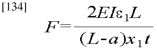
[135] In the same manner as described above, a coordinate of the action position and the intensity of the pressing force F can be obtained in the y-axis direction.
[136] Next, the completely supported touch input structure 100'is described. FIG. 15 shows a case where two strain sensing units 140'are provided, which is a conceptual view schematically showing deformation of the upper layer 1 lO'of the touch input structure lOO'in the x-axis direction. It is assumed that strain of the strain sensing unit 140'positioned at the left side is ε and strain of the strain sensing unit 140'positioned at the right side is ε . The length of the upper layer is L in the x-axis direction, and respective positions of the strain sensing units 140'are x and x whose values are
3 4 already known. Change of strain is detected from the change of the resistance value of the strain sensing unit 140'820O' If a relational expression of the action position and the intensity of the pressing force F is set based on the strain S310' it is as shown in mathematical expression 13. In mathematical expression 13, 'E' denotes an elastic coefficient of the upper layer, T denotes a moment of inertial, and 't' denotes thickness of the upper layer. [137] [Mathematical expression 13]
Fax(L-Cix) t F(L-ax) (L+2ax)x1f 2EIL 2EIL
Fax(L-Ctx)I Fa (3L-2ax)x2t
Z2 =g2(F, ax) = " 3
2EIL 2EIL
[140]
[141] Since the step of acquiring an action position and intensity of a pressing force F S320'and S330'is the same as the case of mathematical expressions 11 and 12 described above, detailed description thereof will be omitted.
[ 142] <Modified embodiment
[143] The method of detecting an action position and intensity of a pressing force F can be based on the Timochenko beam theory or Finite Element Method, in addition to the Euler beam theory. If the method is based on the Finite Element Method, which is a numeric analysis, an action position and intensity of a pressing force F can be accura
tely detected for various forms of touch screens having a boundary condition similar to that of a device such as a cellular phone using a touch input apparatus.
[144] Furthermore, it is apparent that the touch input structure and the touch input apparatus according to the present invention can be used in any apparatus that inputs an operation or position command in a touch input method, as well as in a cellular phone 1 shown in FIG. 5.
[145]
Industrial Applicability
[146] Although the present invention has been described with reference to several preferred embodiments, the description is illustrative of the invention and is not to be construed as limiting the invention. Various modifications and variations may occur to those skilled in the art, without departing from the scope of the invention as defined by the appended claims.
[147]
Claims
[1] A touch input structure for detecting intensity and an action position of a pressing force, the structure comprising: an upper layer on which an external pressing force is applied by a pointing object; a lower layer provided to be spaced apart from the upper layer by a certain distance; a supporting unit provided between the upper layer and the lower layer, for connecting the upper layer and the lower layer; and a strain sensing unit provided on one side of the upper layer, for detecting strain of the upper layer.
[2] The structure according to claim 1, wherein the strain sensing unit is a resistive layer or a strain gauge.
[3] The structure according to claim 2, wherein the resistive layer is a desensitizing ink, ITO, resistive paste, or carbon nano tube.
[4] The structure according to claim 1, wherein the upper and lower layers are a transparent material.
[5] A touch input apparatus comprising: a touch input structure including: an upper layer on which an external pressing force is applied by a pointing object; a lower layer provided to be spaced apart from the upper layer by a certain distance; a supporting unit provided between the upper and lower layers, for connecting the upper and lower layers; and electrodes formed on one side of the upper and lower layers to face with each other; and a detection unit for detecting an action position and intensity of the pressing force based on change of electrostatic capacity between the electrodes occurred by applying the pressing force.
[6] The apparatus according to claim 5, wherein at least two pairs of the electrodes are provided.
[7] The apparatus according to claim 5, wherein the electrodes are metal, ITO, or carbon nano tube.
[8] The apparatus according to claim 5, wherein the upper and lower layers are a transparent material.
[9] The apparatus according to claim 5, wherein the detection unit comprises:
a space change detection unit for detecting change of space between the upper and lower layers at a position where the electrodes are provided; a position detection unit for detecting a position where the pressing force is applied, based on the change of space; and an intensity detection unit for detecting intensity of the pressing force from a relational expression of the detected position and the change of space.
[10] The apparatus according to claim 9, wherein the position detection unit detects the action position by performing an operation related to the change of space and the action position of the pressing force or searching for previously stored data.
[11] The apparatus according to claim 5, wherein since a side surface of the touch input structure is fixed by the supporting unit, displacement and slope of the side surface are unchangeable, or since the side surface is simply supported, and displacement of the side surface is unchangeable.
[12] A touch input apparatus comprising: a touch input structure including: an upper layer on which an external pressing force is applied by a pointing object; a lower layer provided to be spaced apart from the upper layer by a certain distance; and a supporting unit provided between the upper and lower layers, for connecting the upper and lower layers, wherein a strain sensing unit is locally formed on one side of the upper layer, and a detection unit for detecting an action position and intensity of the pressing force based on the strain occurred by applying the pressing force on an area provided with the strain sensing unit.
[13] The apparatus according to claim 12, wherein the strain sensing unit is a resistive layer or a strain gauge.
[14] The apparatus according to claim 12, wherein at least two strain sensing units are provided.
[15] The apparatus according to claim 12, wherein the detection unit comprises: a strain detection unit for detecting strain of the upper layer using the strain sensing unit; a position detection unit for detecting an action position of the pressing force based on the strain; and an intensity detection unit for detecting intensity of the pressing force from a relational expression of the detected action position and strain.
[16] The apparatus according to claim 15, wherein the position detection unit detects the action position by performing an operation related to the strain and the action
position of the pressing force or searching for previously stored data.
[17] The apparatus according to claim 12, wherein since a side surface of the touch input structure is fixed by the supporting unit, displacement and slope of the side surface are unchangeable, or since the side surface is simply supported, displacement of the side surface is unchangeable.
[18] A method of detecting intensity and an action position of a pressing force, the method comprising the steps of: developing deformation of an upper layer as a pressing force is applied to a touch input structure; detecting, by a detection unit, change of space between the upper layer and a lower layer at least at two positions; and detecting, by the detection unit, the action position and intensity of the pressing force based on the change of space.
[19] The method according to claim 18, wherein the step of detecting the action position and intensity of the pressing force is based on an Euler beam theory.
[20] The method according to claim 18, wherein the change of space is detected based on change of electrostatic capacity between the upper and lower layers.
[21] The method according to claim 18, wherein the step of detecting the action position and intensity of the pressing force comprises the steps of: setting a relational expression related to the change of space, a coordinate of the action position, and the strength based on a virtual coordinate system previously formed on the touch input structure; acquiring the coordinate of the action position based on the change of space; and acquiring the strength based on the relational expression and the acquired coordinate.
[22] A method of detecting intensity and an action position of a pressing force, the method comprising the steps of: developing deformation of an upper layer as a pressing force is applied to a touch input structure; detecting, by a detection unit, strain of the upper layer at least at two positions; and detecting, by the detection unit, the action position and intensity of the pressing force based on the strain.
[23] The method according to claim 22, wherein the step of detecting the action position and intensity of the pressing force is based on an Euler beam theory.
[24] The method according to claim 22, wherein the strain is detected based on change of a resistance value of a strain sensing unit formed on the upper layer.
[25] The method according to claim 22, wherein the step of detecting the action position and intensity of the pressing force comprises the steps of: setting a relational expression related to the strain, a coordinate of the action position, and the strength based on a virtual coordinate system previously formed on the touch input structure; acquiring the coordinate of the action position based on the relational expression; and acquiring the strength based on the relational expression and the acquired coordinate.
Applications Claiming Priority (2)
| Application Number | Priority Date | Filing Date | Title |
|---|---|---|---|
| KR10-2008-0078532 | 2008-08-11 | ||
| KR1020080078532A KR100997107B1 (en) | 2008-08-11 | 2008-08-11 | Structure of touch input for acquiring location and intensity of force, apparatus therewith and acquiring method thereof |
Publications (1)
| Publication Number | Publication Date |
|---|---|
| WO2010018889A1 true WO2010018889A1 (en) | 2010-02-18 |
Family
ID=41669023
Family Applications (1)
| Application Number | Title | Priority Date | Filing Date |
|---|---|---|---|
| PCT/KR2008/005888 WO2010018889A1 (en) | 2008-08-11 | 2008-10-08 | Structure of touch input for acquiring location and intensity of force, apparatus therewith and acquiring method thereof |
Country Status (2)
| Country | Link |
|---|---|
| KR (1) | KR100997107B1 (en) |
| WO (1) | WO2010018889A1 (en) |
Cited By (11)
| Publication number | Priority date | Publication date | Assignee | Title |
|---|---|---|---|---|
| WO2013043335A1 (en) * | 2011-09-21 | 2013-03-28 | Synaptics Incorporated | Input device with integrated deformable electrode structure for force sensing |
| EP2821767A1 (en) * | 2012-03-02 | 2015-01-07 | Shiseido Company, Ltd. | Application operation evaluating apparatus and application operation evaluating method |
| US9024907B2 (en) | 2009-04-03 | 2015-05-05 | Synaptics Incorporated | Input device with capacitive force sensor and method for constructing the same |
| US9041418B2 (en) | 2011-10-25 | 2015-05-26 | Synaptics Incorporated | Input device with force sensing |
| US9057653B2 (en) | 2010-05-11 | 2015-06-16 | Synaptics Incorporated | Input device with force sensing |
| US9557857B2 (en) | 2011-04-26 | 2017-01-31 | Synaptics Incorporated | Input device with force sensing and haptic response |
| JP2017134810A (en) * | 2016-01-29 | 2017-08-03 | 三星ディスプレイ株式會社Samsung Display Co.,Ltd. | Sensor, touch sensor, and display |
| EP2732361B1 (en) * | 2011-07-12 | 2018-05-23 | BlackBerry Limited | Electronic device and method of controlling a touch-sensitive display |
| US20180224995A1 (en) * | 2016-11-23 | 2018-08-09 | Shenzhen Goodix Technology Co, Ltd | Force detection method, apparatus and device |
| US10126861B2 (en) | 2015-05-08 | 2018-11-13 | Synaptics Incorporated | Force sensor substrate |
| US10452211B2 (en) | 2016-05-27 | 2019-10-22 | Synaptics Incorporated | Force sensor with uniform response in an axis |
Families Citing this family (6)
| Publication number | Priority date | Publication date | Assignee | Title |
|---|---|---|---|---|
| WO2012087065A2 (en) * | 2010-12-24 | 2012-06-28 | 성균관대학교산학협력단 | Touch sensor using graphin for simultaneously detecting pressure and position |
| KR102008736B1 (en) * | 2012-12-17 | 2019-08-09 | 엘지이노텍 주식회사 | Touch panel and method for driving the same |
| JP6243828B2 (en) | 2013-11-29 | 2017-12-06 | 株式会社 ハイディープHiDeep Inc. | Feedback method according to touch level and touch input device performing the same |
| KR101518786B1 (en) * | 2013-11-29 | 2015-05-15 | 주식회사 하이딥 | Feedback method of touch pressure level and device including touch screen performing the same |
| KR101664771B1 (en) * | 2016-04-29 | 2016-10-10 | 엘지이노텍 주식회사 | Touch panel and method for driving the same |
| WO2018038367A1 (en) | 2016-08-26 | 2018-03-01 | 주식회사 하이딥 | Touch input device including display panel having strain gauge, and method for manufacturing display panel having strain gauge |
Citations (3)
| Publication number | Priority date | Publication date | Assignee | Title |
|---|---|---|---|---|
| US7148882B2 (en) * | 2003-05-16 | 2006-12-12 | 3M Innovatie Properties Company | Capacitor based force sensor |
| US7183948B2 (en) * | 2001-04-13 | 2007-02-27 | 3M Innovative Properties Company | Tangential force control in a touch location device |
| US7190350B2 (en) * | 2001-04-13 | 2007-03-13 | 3M Innovative Properties Company | Touch screen with rotationally isolated force sensor |
-
2008
- 2008-08-11 KR KR1020080078532A patent/KR100997107B1/en not_active IP Right Cessation
- 2008-10-08 WO PCT/KR2008/005888 patent/WO2010018889A1/en active Application Filing
Patent Citations (3)
| Publication number | Priority date | Publication date | Assignee | Title |
|---|---|---|---|---|
| US7183948B2 (en) * | 2001-04-13 | 2007-02-27 | 3M Innovative Properties Company | Tangential force control in a touch location device |
| US7190350B2 (en) * | 2001-04-13 | 2007-03-13 | 3M Innovative Properties Company | Touch screen with rotationally isolated force sensor |
| US7148882B2 (en) * | 2003-05-16 | 2006-12-12 | 3M Innovatie Properties Company | Capacitor based force sensor |
Cited By (19)
| Publication number | Priority date | Publication date | Assignee | Title |
|---|---|---|---|---|
| US9024907B2 (en) | 2009-04-03 | 2015-05-05 | Synaptics Incorporated | Input device with capacitive force sensor and method for constructing the same |
| US9057653B2 (en) | 2010-05-11 | 2015-06-16 | Synaptics Incorporated | Input device with force sensing |
| US9557857B2 (en) | 2011-04-26 | 2017-01-31 | Synaptics Incorporated | Input device with force sensing and haptic response |
| EP2732361B1 (en) * | 2011-07-12 | 2018-05-23 | BlackBerry Limited | Electronic device and method of controlling a touch-sensitive display |
| US9748952B2 (en) | 2011-09-21 | 2017-08-29 | Synaptics Incorporated | Input device with integrated deformable electrode structure for force sensing |
| WO2013043335A1 (en) * | 2011-09-21 | 2013-03-28 | Synaptics Incorporated | Input device with integrated deformable electrode structure for force sensing |
| US9671898B2 (en) | 2011-10-25 | 2017-06-06 | Synaptics Incorporated | Input device with force sensing |
| US9041418B2 (en) | 2011-10-25 | 2015-05-26 | Synaptics Incorporated | Input device with force sensing |
| US9405394B2 (en) | 2012-03-02 | 2016-08-02 | Shiseido Company, Ltd. | Application operation evaluating apparatus and application operation evaluating method |
| EP2821767A4 (en) * | 2012-03-02 | 2015-03-25 | Shiseido Co Ltd | Application operation evaluating apparatus and application operation evaluating method |
| EP2821767A1 (en) * | 2012-03-02 | 2015-01-07 | Shiseido Company, Ltd. | Application operation evaluating apparatus and application operation evaluating method |
| US10126861B2 (en) | 2015-05-08 | 2018-11-13 | Synaptics Incorporated | Force sensor substrate |
| JP2017134810A (en) * | 2016-01-29 | 2017-08-03 | 三星ディスプレイ株式會社Samsung Display Co.,Ltd. | Sensor, touch sensor, and display |
| US10452211B2 (en) | 2016-05-27 | 2019-10-22 | Synaptics Incorporated | Force sensor with uniform response in an axis |
| US20180224995A1 (en) * | 2016-11-23 | 2018-08-09 | Shenzhen Goodix Technology Co, Ltd | Force detection method, apparatus and device |
| EP3351915A4 (en) * | 2016-11-23 | 2018-11-14 | Shenzhen Goodix Technology Co., Ltd. | Method, device and equipment for detecting pressure |
| CN108885144A (en) * | 2016-11-23 | 2018-11-23 | 深圳市汇顶科技股份有限公司 | A kind of pressure detection method, device and equipment |
| US10534469B2 (en) * | 2016-11-23 | 2020-01-14 | Shenzhen GOODIX Technology Co., Ltd. | Force detection method, apparatus and device |
| CN108885144B (en) * | 2016-11-23 | 2021-03-16 | 深圳市汇顶科技股份有限公司 | Pressure detection method, device and equipment |
Also Published As
| Publication number | Publication date |
|---|---|
| KR100997107B1 (en) | 2010-11-29 |
| KR20100019808A (en) | 2010-02-19 |
Similar Documents
| Publication | Publication Date | Title |
|---|---|---|
| WO2010018889A1 (en) | Structure of touch input for acquiring location and intensity of force, apparatus therewith and acquiring method thereof | |
| KR100969504B1 (en) | Touch inputting apparatus integral sensors | |
| CN105975137B (en) | Touch display panel and touch display device | |
| JP4545168B2 (en) | Force imaging input devices and systems | |
| US8125454B2 (en) | Resistive type touch panel | |
| US8711122B2 (en) | Sensor apparatus and information processing apparatus | |
| US7190350B2 (en) | Touch screen with rotationally isolated force sensor | |
| US9383848B2 (en) | Interleaved piezoelectric tactile interface | |
| WO2018000874A1 (en) | Touch pressure detection apparatus, display screen and touch control electronic device | |
| US20100117989A1 (en) | Touch panel module and touch panel system with same | |
| WO2009094200A1 (en) | Integrated force sensitive lens and software | |
| WO2013154850A2 (en) | Apparatus and method for a pressure sensitive device interface | |
| KR20040060849A (en) | Touch screen with rotationally isolated force sensor | |
| KR20110128781A (en) | Sensor device and information processing device | |
| KR20110123093A (en) | Touch screen device | |
| JP2006507600A (en) | Touch display | |
| KR101124225B1 (en) | Touch inputting apparatus with integral sensors and method for fabricating thereof | |
| KR20100033076A (en) | Touch screen with touch pressure sensing function | |
| WO2017190399A1 (en) | Pressure sensing module, terminal, and image display method and apparatus | |
| KR20190004679A (en) | Touch device, touch display device and driving method for touch device | |
| US11928292B2 (en) | Touchscreen device | |
| KR101924546B1 (en) | Apparatus for measuring pressure | |
| WO2016117786A1 (en) | Multi-scale digitizer system | |
| CN102063219A (en) | Touch display module and operation method |
Legal Events
| Date | Code | Title | Description |
|---|---|---|---|
| 121 | Ep: the epo has been informed by wipo that ep was designated in this application |
Ref document number: 08812371 Country of ref document: EP Kind code of ref document: A1 |
|
| NENP | Non-entry into the national phase |
Ref country code: DE |
|
| 122 | Ep: pct application non-entry in european phase |
Ref document number: 08812371 Country of ref document: EP Kind code of ref document: A1 |