WO2009088647A1 - Fluid filtration articles and methods of making and using the same - Google Patents
Fluid filtration articles and methods of making and using the same Download PDFInfo
- Publication number
- WO2009088647A1 WO2009088647A1 PCT/US2008/086766 US2008086766W WO2009088647A1 WO 2009088647 A1 WO2009088647 A1 WO 2009088647A1 US 2008086766 W US2008086766 W US 2008086766W WO 2009088647 A1 WO2009088647 A1 WO 2009088647A1
- Authority
- WO
- WIPO (PCT)
- Prior art keywords
- layer
- population
- fibers
- fluid
- fluid filtration
- Prior art date
Links
Classifications
-
- B—PERFORMING OPERATIONS; TRANSPORTING
- B01—PHYSICAL OR CHEMICAL PROCESSES OR APPARATUS IN GENERAL
- B01D—SEPARATION
- B01D39/00—Filtering material for liquid or gaseous fluids
- B01D39/02—Loose filtering material, e.g. loose fibres
- B01D39/04—Organic material, e.g. cellulose, cotton
-
- B—PERFORMING OPERATIONS; TRANSPORTING
- B01—PHYSICAL OR CHEMICAL PROCESSES OR APPARATUS IN GENERAL
- B01D—SEPARATION
- B01D39/00—Filtering material for liquid or gaseous fluids
- B01D39/14—Other self-supporting filtering material ; Other filtering material
- B01D39/16—Other self-supporting filtering material ; Other filtering material of organic material, e.g. synthetic fibres
- B01D39/1607—Other self-supporting filtering material ; Other filtering material of organic material, e.g. synthetic fibres the material being fibrous
- B01D39/1623—Other self-supporting filtering material ; Other filtering material of organic material, e.g. synthetic fibres the material being fibrous of synthetic origin
-
- C—CHEMISTRY; METALLURGY
- C02—TREATMENT OF WATER, WASTE WATER, SEWAGE, OR SLUDGE
- C02F—TREATMENT OF WATER, WASTE WATER, SEWAGE, OR SLUDGE
- C02F1/00—Treatment of water, waste water, or sewage
- C02F1/001—Processes for the treatment of water whereby the filtration technique is of importance
- C02F1/003—Processes for the treatment of water whereby the filtration technique is of importance using household-type filters for producing potable water, e.g. pitchers, bottles, faucet mounted devices
-
- B—PERFORMING OPERATIONS; TRANSPORTING
- B01—PHYSICAL OR CHEMICAL PROCESSES OR APPARATUS IN GENERAL
- B01D—SEPARATION
- B01D2239/00—Aspects relating to filtering material for liquid or gaseous fluids
- B01D2239/04—Additives and treatments of the filtering material
- B01D2239/0407—Additives and treatments of the filtering material comprising particulate additives, e.g. adsorbents
-
- B—PERFORMING OPERATIONS; TRANSPORTING
- B01—PHYSICAL OR CHEMICAL PROCESSES OR APPARATUS IN GENERAL
- B01D—SEPARATION
- B01D2239/00—Aspects relating to filtering material for liquid or gaseous fluids
- B01D2239/06—Filter cloth, e.g. knitted, woven non-woven; self-supported material
- B01D2239/0604—Arrangement of the fibres in the filtering material
- B01D2239/0618—Non-woven
-
- B—PERFORMING OPERATIONS; TRANSPORTING
- B01—PHYSICAL OR CHEMICAL PROCESSES OR APPARATUS IN GENERAL
- B01D—SEPARATION
- B01D2239/00—Aspects relating to filtering material for liquid or gaseous fluids
- B01D2239/06—Filter cloth, e.g. knitted, woven non-woven; self-supported material
- B01D2239/0604—Arrangement of the fibres in the filtering material
- B01D2239/0636—Two or more types of fibres present in the filter material
-
- B—PERFORMING OPERATIONS; TRANSPORTING
- B01—PHYSICAL OR CHEMICAL PROCESSES OR APPARATUS IN GENERAL
- B01D—SEPARATION
- B01D2239/00—Aspects relating to filtering material for liquid or gaseous fluids
- B01D2239/06—Filter cloth, e.g. knitted, woven non-woven; self-supported material
- B01D2239/065—More than one layer present in the filtering material
- B01D2239/0654—Support layers
-
- B—PERFORMING OPERATIONS; TRANSPORTING
- B01—PHYSICAL OR CHEMICAL PROCESSES OR APPARATUS IN GENERAL
- B01D—SEPARATION
- B01D2239/00—Aspects relating to filtering material for liquid or gaseous fluids
- B01D2239/12—Special parameters characterising the filtering material
- B01D2239/1233—Fibre diameter
-
- C—CHEMISTRY; METALLURGY
- C02—TREATMENT OF WATER, WASTE WATER, SEWAGE, OR SLUDGE
- C02F—TREATMENT OF WATER, WASTE WATER, SEWAGE, OR SLUDGE
- C02F1/00—Treatment of water, waste water, or sewage
- C02F1/28—Treatment of water, waste water, or sewage by sorption
- C02F1/283—Treatment of water, waste water, or sewage by sorption using coal, charred products, or inorganic mixtures containing them
-
- C—CHEMISTRY; METALLURGY
- C02—TREATMENT OF WATER, WASTE WATER, SEWAGE, OR SLUDGE
- C02F—TREATMENT OF WATER, WASTE WATER, SEWAGE, OR SLUDGE
- C02F1/00—Treatment of water, waste water, or sewage
- C02F1/42—Treatment of water, waste water, or sewage by ion-exchange
- C02F2001/425—Treatment of water, waste water, or sewage by ion-exchange using cation exchangers
-
- Y—GENERAL TAGGING OF NEW TECHNOLOGICAL DEVELOPMENTS; GENERAL TAGGING OF CROSS-SECTIONAL TECHNOLOGIES SPANNING OVER SEVERAL SECTIONS OF THE IPC; TECHNICAL SUBJECTS COVERED BY FORMER USPC CROSS-REFERENCE ART COLLECTIONS [XRACs] AND DIGESTS
- Y10—TECHNICAL SUBJECTS COVERED BY FORMER USPC
- Y10T—TECHNICAL SUBJECTS COVERED BY FORMER US CLASSIFICATION
- Y10T442/00—Fabric [woven, knitted, or nonwoven textile or cloth, etc.]
- Y10T442/60—Nonwoven fabric [i.e., nonwoven strand or fiber material]
- Y10T442/608—Including strand or fiber material which is of specific structural definition
- Y10T442/614—Strand or fiber material specified as having microdimensions [i.e., microfiber]
- Y10T442/626—Microfiber is synthetic polymer
-
- Y—GENERAL TAGGING OF NEW TECHNOLOGICAL DEVELOPMENTS; GENERAL TAGGING OF CROSS-SECTIONAL TECHNOLOGIES SPANNING OVER SEVERAL SECTIONS OF THE IPC; TECHNICAL SUBJECTS COVERED BY FORMER USPC CROSS-REFERENCE ART COLLECTIONS [XRACs] AND DIGESTS
- Y10—TECHNICAL SUBJECTS COVERED BY FORMER USPC
- Y10T—TECHNICAL SUBJECTS COVERED BY FORMER US CLASSIFICATION
- Y10T442/00—Fabric [woven, knitted, or nonwoven textile or cloth, etc.]
- Y10T442/60—Nonwoven fabric [i.e., nonwoven strand or fiber material]
- Y10T442/68—Melt-blown nonwoven fabric
-
- Y—GENERAL TAGGING OF NEW TECHNOLOGICAL DEVELOPMENTS; GENERAL TAGGING OF CROSS-SECTIONAL TECHNOLOGIES SPANNING OVER SEVERAL SECTIONS OF THE IPC; TECHNICAL SUBJECTS COVERED BY FORMER USPC CROSS-REFERENCE ART COLLECTIONS [XRACs] AND DIGESTS
- Y10—TECHNICAL SUBJECTS COVERED BY FORMER USPC
- Y10T—TECHNICAL SUBJECTS COVERED BY FORMER US CLASSIFICATION
- Y10T442/00—Fabric [woven, knitted, or nonwoven textile or cloth, etc.]
- Y10T442/60—Nonwoven fabric [i.e., nonwoven strand or fiber material]
- Y10T442/699—Including particulate material other than strand or fiber material
Definitions
- the present disclosure relates to fluid filtration articles and methods of making and using such articles.
- the disclosure further relates to composite nonwoven fibrous webs including fine fibers, such as sub-micrometer fibers and microfibers, useful in fluid filtration articles.
- Nonwoven fibrous webs are frequently used as a filtration medium in such fluid filtration systems.
- Such nonwoven fibrous webs may include two or more kinds of fibers, for example, two different populations of microfibers, each having a different average diameter, so that the nonwoven fibrous web can filter particles of a broad range of sizes.
- the different populations of fibers are intermixed within a single-layer web.
- SMS Short Stream
- spunbond-Meltblown-Spunbond webs comprising a layer of spunbond fibers, a layer of meltblown microfibers, and another layer of spunbond fibers.
- sorbent particulates such as activated carbon
- the disclosure relates to an article in the form of a composite nonwoven fibrous web comprising a population of coarse micro fibers having a population median diameter of at least 1 micrometer ( ⁇ m) formed as a first layer, and a population of fine fibers having a population median diameter less than 10 ⁇ m formed as a second layer adjoining the first layer.
- At least one of the fiber populations may be oriented.
- the coarse microfibers and fine fibers are polymeric, the coarse micro fiber population has a population median diameter of at least 1 ⁇ m, and the fine fiber population has a population median diameter less than 10 ⁇ m.
- the population of fine fibers has a population median diameter less than 1 ⁇ m.
- At least one of the fiber populations may be oriented.
- one or both of the first and second layers comprises a plurality of particulates.
- the disclosure relates to a fluid filtration medium comprising a composite nonwoven fibrous web further comprising a population of microfibers having a median diameter of at least 1 ⁇ m formed as a first layer, and a population of sub-micrometer fibers having a median diameter less than one micrometer ( ⁇ m) formed as a second layer adjoining the first layer. At least one of the fiber populations may be oriented. In certain exemplary embodiments, at least the first layer comprises a plurality of particulates, which may be sorbent particulates.
- the disclosure relates to a method of using the fluid filtration media as described above, comprising passing a permeating fluid through the first and second layers, wherein the permeating fluid passes through the first layer before passing through the second layer.
- the second layer is pleated, and the permeating fluid passes through the second layer before passing through the first layer.
- the disclosure relates to a method of making a fluid filtration medium comprising a composite nonwoven fibrous web, comprising forming a first layer comprising a population of coarse polymeric micro fibers having a population median fiber diameter of at least 1 ⁇ m, forming a second layer comprising a population of fine polymeric micro fibers having a population median fiber diameter of less than 10 ⁇ m, orienting one or both of the first and second layer, and bonding the first layer to the second layer.
- one or both of the first and second layers comprises a plurality of particulates.
- the disclosure relates to a method of making a fluid filtration medium comprising a composite nonwoven fibrous web further comprising forming a first layer comprising a population of micro fibers having a median fiber diameter of at least 1 ⁇ m, and forming a second layer impinging on the first layer, the second layer including a population of sub-micrometer fibers having a median fiber diameter of less than 1 ⁇ m, wherein at least one of the fiber populations may be oriented.
- at least the first layer comprises a plurality of particulates, which may be sorbent particulates.
- the disclosure relates to a fluid filtration article comprising a population of micro fibers having a population median diameter of at least 1 ⁇ m formed as a first layer; a population of sub-micrometer fibers having a population median diameter less than one micrometer ( ⁇ m) formed as a second layer adjoining the first layer; and a fluid-impermeable housing surrounding the first and second layers, wherein the housing comprises at least one fluid inlet in fluid communication with the first layer, and at least one fluid outlet in fluid communication with the second layer.
- the fluid may be a liquid, for example, water.
- the fluid may be a gas, for example, air.
- Figure IA is a schematic illustration of an exemplary porous composite nonwoven fibrous web for producing a fluid filtration medium
- Figure IB is a schematic illustration of an exemplary porous, particle-loaded composite nonwoven fibrous web for producing a fluid filtration medium
- Figure 2 is a schematic illustration of an exemplary porous composite nonwoven fibrous web stack for producing a fluid filtration medium
- Figure 3 is a schematic illustration of the exemplary porous composite nonwoven fibrous web stack of Figure 2 used in an exemplary fluid filtration article
- Figure 4 is a cross-section of an exemplary cylindrically wound porous web stack useful in an exemplary fluid filtration article
- Figure 5 is a cross-section end view of the exemplary cylindrically wound porous web stack according to Figure 4, configured for use as an illustrative embodiment of a fluid filtration article;
- Figure 6 is a cross-section end view of the exemplary cylindrically wound porous web stack according to Figure 4, configured for use as another illustrative embodiment of a fluid filtration article;
- Figure 7 is a graph showing turbidity as a function of permeate volume for exemplary fluid filtration article according to the present disclosure;
- Figure 8 is another graph showing turbidity as a function of permeate volume for exemplary fluid filtration article according to the present disclosure.
- Figure 9 is an additional graph showing turbidity as a function of permeate volume for exemplary fluid filtration article according to the present disclosure.
- Figure 10 is a scanning electron micrograph of a layer within an exemplary fluid filtration article according to the present disclosure.
- Micro fibers means fibers having a median diameter of at least one micrometer ( ⁇ m).
- Coarse microfibers means microfibers having a median diameter of at least 10 ⁇ m.
- Fine microfibers means microfibers having a median diameter of less than 10 ⁇ m.
- Ultratrafine microfibers means microfibers having a median diameter of 2 ⁇ m or less.
- Sub-micrometer fibers means fibers having a median diameter of less than 1 ⁇ m.
- an array of sub-micrometer fibers it means the complete population of microfibers in that array, or the complete population of a single batch of microfibers, and not only that portion of the array or batch that is of sub-micrometer dimensions.
- Continuous oriented microfibers means essentially continuous fibers issuing from a die and traveling through a processing station in which the fibers are permanently drawn and at least portions of the polymer molecules within the fibers are permanently oriented into alignment with the longitudinal axis of the fibers ("oriented" as used with respect to fibers means that at least portions of the polymer molecules of the fibers are aligned along the longitudinal axis of the fibers).
- Meltblown fibers means fibers prepared by extruding molten fiber-forming material through orifices in a die into a high-velocity gaseous stream, where the extruded material is first attenuated and then solidifies as a mass of fibers.
- “Separately prepared microfibers” means a stream of microfibers produced from a microfiber-forming apparatus (e.g., a die) positioned such that the microfiber stream is initially spatially separate (e.g., over a distance of about 1 inch (25 mm) or more from, but will merge in flight and disperse into, a stream of larger size microfibers.
- a microfiber-forming apparatus e.g., a die
- “Nonwoven web” means a fibrous web characterized by entanglement or point bonding of the fibers.
- Self-supporting means a web having sufficient coherency and strength so as to be drapable and handleable without substantial tearing or rupture.
- Web basis weight is calculated from the weight of a 10 cm x 10 cm web sample.
- Web thickness is measured on a 10 cm x 10 cm web sample using a thickness testing gauge having a tester foot with dimensions of 5 cm x 12.5 cm at an applied pressure of 150 Pa.
- Bink density is the mass per unit volume of the bulk polymer or polymer blend that makes up the web, taken from the literature.
- Effective Fiber Diameter is the apparent diameter of the fibers in a fiber web based on an air permeation test in which air at 1 atmosphere and room temperature is passed through a web sample at a specified thickness and face velocity (typically 5.3 cm/sec), and the corresponding pressure drop is measured. Based on the measured pressure drop, the Effective Fiber Diameter is calculated as set forth in Davies, CN. , The Separation of Airborne Dust and Particles, Institution of Mechanical Engineers, London Proceedings, IB (1952).
- Molecularly same polymer means polymers that have essentially the same repeating molecular unit, but which may differ in molecular weight, method of manufacture, commercial form, and the like.
- Meltblowing and “meltblown process” means a method for forming a nonwoven web by extruding a fiber- forming material through a plurality of orifices to form filaments while contacting the filaments with air or other attenuating fluid to attenuate the filaments into fibers and thereafter collecting a layer of the attenuated fibers.
- “Attenuating the filaments into fibers” means the conversion of a segment of a filament into a segment of greater length and smaller diameter.
- “Spunbonding” and “spun bond process” means a method for forming a nonwoven web by extruding a low viscosity melt through a plurality of orifices to form filaments, quenching the filaments with air or other fluid to solidify at least the surfaces of the filaments, contacting the at least partially solidified filaments with air or other fluid to attenuate the filaments into fibers and collecting and optionally calendering a layer of the attenuated fibers.
- "Spun bond fibers” means fibers made using a spun bond process. Such fibers are generally continuous and are entangled or point bonded sufficiently that it is usually not possible to remove one complete spun bond fiber from a mass of such fibers.
- Die means a processing assembly for use in polymer melt processing and fiber extrusion processes, including but not limited to meltblowing and the spunbonding processes.
- particle and particulate are used substantially interchangeably.
- a particle or particulate means a small distinct piece or individual part of a material in finely divided form.
- a particulate may also include a collection of individual particles associated or clustered together in finely divided form.
- individual particles used in certain exemplary embodiments of the present disclosure may clump, physically intermesh, electro-statically associate, or otherwise associate to form particulates.
- particulates in the form of agglomerates of individual particles may be intentionally formed such as those described in U.S. Patent No. 5,332,426 (Tang et al.).
- Particle-loaded meltblown media or “composite nonwoven fibrous web” means a nonwoven web having an open-structured entangled mass of fibers, for example, sub-micrometer fibers and optionally microfibers, containing particles enmeshed among the fibers, the particles optionally being absorbent and/or adsorbent.
- Enmeshed means that particles are dispersed and physically held in the fibers of the web. Generally, there is point and line contact along the fibers and the particles so that nearly the full surface area of the particles is available for interaction with a fluid.
- “Autogenous bonding” means bonding between fibers at an elevated temperature as obtained in an oven or with a through-air bonder without application of solid contact pressure such as in point-bonding or calendering.
- “Calendering” means a process of passing a product, such as a polymeric absorbent loaded web through rollers to obtain a compressed material. The rollers may optionally be heated.
- Densification means a process whereby fibers which have been deposited either directly or indirectly onto a filter winding arbor or mandrel are compressed, either before or after the deposition, and made to form an area, generally or locally, of lower porosity, whether by design or as an artifact of some process of handling the forming or formed filter. Densification also includes the process of calendering webs.
- Fluid treatment unit means an article containing a fluid filtration medium, such as a porous composite nonwoven fibrous web. These articles typically include a filter housing for a fluid filtration medium and an outlet to pass treated fluid away from the filter housing in an appropriate manner.
- the term “fluid filtration system” also includes any related method of separating raw fluid, such as untreated gas or liquid, from treated fluid.
- Vehicle volume means a percentage or fractional value for the unfilled space within a porous body such as a filter, calculated by measuring the weight and volume of a filter, then comparing the filter weight to the theoretical weight a solid mass of the same constituent material of that same volume.
- Porcity means a measure of void spaces in a material. Size, frequency, number, and/or interconnectivity of pores and voids contribute the porosity of a material.
- Layer means a single stratum formed between two major surfaces.
- a layer may exist internally within a single web, e.g., a single stratum formed with multiple strata in a single web have first and second major surfaces defining the thickness of the web.
- a layer may also exist in a composite article comprising multiple webs, e.g., a single stratum in a first web having first and second major surfaces defining the thickness of the web, when that web is overlaid or underlaid by a second web having first and second major surfaces defining the thickness of the second web, in which case each of the first and second webs forms at least one layer.
- layers may simultaneously exist within a single web and between that web and one or more other webs, each web forming a layer.
- “Adjoining" with reference to a particular first layer means joined with or attached to another, second layer, in a position wherein the first and second layers are either next to
- Porate density gradient means that the amount of particulate, sorbent or fibrous material within a particular fiber population (e.g., the number, weight or volume of a given material per unit volume over a defined area of the web) need not be uniform throughout the composite nonwoven fibrous web, and that it can vary to provide more material in certain areas of the web and less in other areas.
- the disclosure provides an article in the form of a composite nonwoven fibrous web comprising a population of micro fibers or coarse micro fibers having a population median diameter of at least 1 micrometer ( ⁇ m) formed as a first layer, and a population of fine fibers having a population median diameter less than 10 ⁇ m formed as a second layer adjoining the first layer. At least one of the fiber populations may be oriented.
- the coarse microf ⁇ bers and fine fibers are polymeric, the micro fiber or coarse micro fiber population has a population median diameter of at least 1 ⁇ m, and the fine fiber population has a population median diameter less than 10 ⁇ m. In another exemplary embodiment, the population of fine fibers has a population median diameter less than 1 ⁇ m. At least one of the fiber populations may be oriented. In certain embodiments, one or both of the first and second layers comprises a plurality of particulates.
- the disclosure provides a fluid filtration medium in the form of a composite nonwoven fibrous web further comprising a population of micro fibers having a median diameter of at least 1 ⁇ m formed as a first layer, and a population of sub-micrometer fibers having a median diameter less than one micrometer ( ⁇ m) formed as a second layer adjoining the first layer. At least one of the fiber populations may be oriented. In certain exemplary embodiments, at least the first layer comprises a plurality of particulates, which may be sorbent particulates.
- Oriented fibers are fibers where there is molecular orientation within the fiber. Fully oriented and partially oriented polymeric fibers are known and commercially available. Orientation of fibers can be measured in a number of ways, including birefringence, heat shrinkage, X-ray scattering, and elastic modulus (see e.g., Principles of Polymer Processing, Zehev Tadmor and Costas Gogos, John Wiley and Sons, New York, 1979, pp. 77-84). It is important to note that molecular orientation is distinct from crystallinity, as both crystalline and amorphous materials can exhibit molecular orientation independent from crystallization.
- the composite nonwoven fibrous web 10 comprises a first layer comprising a population of micro fibers 12, overlaid by a second layer 14 which may comprise a population of fine microfibers, ultrafme microfibers, and/or sub-micrometer fibers.
- the population of microfibers 12 may be coarse microfibers.
- a gradient of fiber population median diameter from coarse to fine is shown across the thickness T of the web 10.
- other gradients may be used; for example, a gradient of fiber population median diameter from fine to coarse across the thickness of the web.
- a gradient of particulate concentration and/or particulate size may be created across or through the thickness of one or both layers.
- additional layers (not shown), including an optional support layer (not shown), may also be included in other exemplary embodiments.
- the first (e.g., micro fiber) layer may overlay the second (e.g., fine fiber) layer.
- FIG. IB is a schematic of another exemplary composite nonwoven fibrous article for producing a fluid filtration medium according to an exemplary embodiment of the present disclosure is illustrated.
- the composite nonwoven fibrous web 10 comprises a first layer comprising a population of microfibers 12, overlaid by a second layer which may comprise a population of fine microfibers, ultrafme microfibers, and/or sub-micrometer fibers.
- the population of microfibers 12 may be coarse microfibers.
- a plurality of particulates 16 is distributed among the microfibers 12 in the first layer.
- a gradient of fiber population median diameter from coarse to fine is shown across the thickness T of the web 10.
- the first (e.g., micro fiber) layer may overlay the second (e.g., fine fiber) layer. Additional layers (not shown), including an optional support layer (not shown), may also be included in other exemplary embodiments.
- FIG. 2 is a schematic of another exemplary composite nonwoven fibrous article for producing a fluid filtration medium or element according to an exemplary embodiment of the present disclosure is illustrated.
- the composite nonwoven fibrous element 24 comprises two webs overlaid to form two distinct layers.
- a first layer 20, comprising a population of micro fibers 12 is overlaid by a second layer 10', which may comprise a population of fine microfibers, ultrafine microfibers, and/or sub-micrometer fibers 14.
- the population of microfibers 12 may be coarse microfibers.
- a plurality of particulates 16 is distributed among the population of microfibers 12 in the first layer 20.
- the first (e.g., microfiber) layer 20 may overlay the second (e.g., fine fiber) layer 10'.
- additional layers may be formed by additional overlaid or underlaid webs, or by forming a gradient of fiber population median diameter (e.g., from coarse to fine, fine to coarse, and the like), particulate population mean diameter (e.g., from coarse to fine, fine to coarse, and the like), and/or particulate concentration expressed, for example, as a mass of particulates per mass of fibers (e.g., from high to low concentration, low to high concentration, and the like) across the thickness T of the composite nonwoven fibrous article 10'.
- the disclosure relates to a fluid filtration article comprising a population of microfibers having a population median diameter of at least 1 ⁇ m formed as a first layer; a population of sub-micrometer fibers having a population median diameter less than one micrometer ( ⁇ m) formed as a second layer adjoining the first layer; and a fluid-impermeable housing surrounding the first and second layers, wherein the housing comprises at least one fluid inlet in fluid communication with the first layer, and at least one fluid outlet in fluid communication with the second layer.
- the fluid may be a liquid, for example, water.
- the fluid may be a gas, for example, air.
- Figure 3 is a schematic illustration of the exemplary multi-layer composite nonwoven fibrous web of Figure 2 used in an exemplary stacked fluid filtration article 28, wherein the fluid is a gas such as, for example, air. While Figure 3 is described in terms of gas filtration, it is to be understood that other fluids, for example liquids (e.g., water), may be used.
- a gas such as, for example, air.
- Figure 3 shows a cross-sectional view of the exemplary fluid (e.g., gas) filtration article 28, which may be useful as, for example, a respirator.
- exemplary fluid (e.g., gas) filtration article 28 uses the composite nonwoven fibrous element 24 shown in Figure 2 in a stacked configuration.
- Composite nonwoven fibrous element 24 comprises two webs overlaid to form two distinct layers.
- a first layer 20, comprising a population of micro fibers (12 in Figure 2) is overlaid and adjoined by a second layer 10', which may comprise a population of fine micro fibers, ultrafme micro fibers, and/or sub-micrometer fibers (14 in Figure 2).
- the population of micro fibers (12 in Figure 2) may be coarse microf ⁇ bers.
- a plurality of particulates 16 is distributed in the first layer 20.
- the first (e.g., micro fiber) layer 20 may overlay and adjoin the second (e.g., fine fiber) layer 10'.
- additional layers may be formed by additional adjoining overlaid or underlaid webs, or by forming a gradient of fiber population median diameter (e.g., from coarse to fine, fine to coarse, and the like), particulate population mean diameter (e.g., from coarse to fine, fine to coarse, and the like), and/or particulate concentration expressed, for example, as a mass of particulates per mass of fibers (e.g., from high to low concentration, low to high concentration, and the like) across the thickness T of the composite nonwoven fibrous element 24.
- a gradient of fiber population median diameter e.g., from coarse to fine, fine to coarse, and the like
- particulate population mean diameter e.g., from coarse to fine, fine to coarse, and the like
- particulate concentration expressed, for example, as a mass of particulates per mass of fibers (e.g., from high to low concentration, low to high concentration, and the like) across the thickness T of the composite nonwoven fibrous element 24.
- exemplary fluid (e.g., gas) filtration article 28 can be at least partially filled with the composite nonwoven fibrous element 24.
- the housing 29 includes at least one fluid inlet 23 in fluid communication with the first layer 20, and at least one fluid outlet 25 in fluid communication with the second layer 10'. For example, as shown in FIG.
- fluid e.g., ambient air
- fluid e.g., gas
- inlet openings 23 in perforated cover 22 of housing 29 passes through composite nonwoven fibrous element 24 (whereupon potentially hazardous substances in such fluid may be absorbed and/or adsorbed by particulates 16 distributed in first layer 20) and exits fluid (e.g., gas) filtration article 28 through fluid outlet opening 25 (e.g., air valve 25 mounted on support 26 of housing 29.
- Flange 27 enables fluid (e.g., gas) filtration article 28 to be replaceably attached to a fluid (e.g., gas) filtration device such as a respirator (not shown). Suitable respirators are known to those skilled in the art.
- the exemplary fluid (e.g., gas) filtration article 28 uses the composite nonwoven fibrous element 24 shown in Figure 2.
- other composite nonwoven fibrous articles for example, those illustrated or described in the description of Figures IA and IB, may be used.
- the first (e.g., microfiber) layer 20 may overlay the second (e.g., fine fiber) layer 10'.
- additional layers may be formed by additional overlaid or underlaid webs, or by forming a gradient of fiber population median diameter (e.g., from coarse to fine, fine to coarse, and the like), particulate population mean diameter (e.g., from coarse to fine, fine to coarse, and the like), and/or particulate concentration expressed, for example, as a mass of particulates per mass of fibers (e.g., from high to low concentration, low to high concentration) across the thickness T of the composite nonwoven fibrous element 10', as illustrated in Figures IA and IB.
- the additional layers may include an optional support layer (not shown) as described herein.
- Figure 4 is a cross-section of an exemplary cylindrically wound porous web useful in a cylindrical fluid filtration medium 30.
- the composite nonwoven fibrous web 10 of Figure IA has been wound to form a cylinder having a hollow core 35, the cylinder wound such that first microfiber layer 12, comprising a population of micro fibers, forms an outer radial layer overlaid by second fine fiber layer 14, which may comprise a population of fine microfibers, ultrafine microfibers, and/or sub-micrometer fibers.
- the population of micro fibers may be coarse microfibers.
- a gradient of fiber population median diameter from coarse to fine is shown across the thickness T of the web 10 in moving in the radial direction from the outer edge of the first microfiber layer 12 to the outer edge of the hollow core 35.
- a gradient of fiber population median diameter from fine to coarse in moving in the radial direction from the outer edge of the first microfiber layer to the outer edge of the hollow core may be used.
- the first (e.g., microfiber) layer may overlay the second (e.g., fine fiber) layer.
- one or both of the first layer and second layer may comprise a plurality of particulates (not shown in Figure 4).
- the plurality of particulates may be distributed in one or both of the first micro fiber layer and the second fine fiber layer so as to exhibit a gradient (not shown in Figure 4) of particulate population mean diameter (e.g., from coarse to fine, fine to coarse, and the like), and/or particulate concentration expressed, for example, as a mass of particulates per mass of fibers (e.g., from high to low concentration, low to high concentration, and the like) across the thickness T of the web 10 in the radial direction.
- Additional layers (not shown), including an optional support layer (not shown), may also be included in additional exemplary embodiments.
- Figure 5 is a cross-section end view of an exemplary embodiment of a cylindrically wound porous web according to the concepts illustrated by Figure 4, configured for use as an illustrative embodiment of a cylindrical fluid filtration medium 30.
- the composite nonwoven fibrous web 24 illustrated by Figure 2, shown in Figure 5 without the optional particulates (16 in Figure 2), is shown wound into a cylinder around a porous cylindrical mesh layer 36 positioned within hollow core 35 adjoining second layer 14, comprising a population of fine microfibers, ultrafme microfibers, and/or sub-micrometer fibers.
- First layer 12, comprising a population of microfibers forms an outer radial layer overlaid by second layer 14.
- the population of microfibers may be coarse microfibers.
- a gradient of fiber population median diameter from coarse to fine is shown across the web 10 in the radial direction.
- the first (e.g., microfiber) layer may overlay the second (e.g., fine fiber) layer.
- a gradient of fiber population median diameter from fine to coarse in moving in the radial direction from the outer edge of the first microfiber layer to the outer edge of the porous cylindrical mesh layer may be used.
- the first (e.g., microfiber) layer may overlay the second (e.g., fine fiber) layer.
- one or both of the first layer and second layer may comprise a plurality of particulates (not shown in Figure 5).
- the plurality of particulates may be distributed in one or both of the first microfiber layer and the second fine fiber layer so as to exhibit a gradient (not shown in Figure 5) of particulate population mean diameter (e.g., from coarse to fine, fine to coarse, and the like), and/or particulate concentration expressed, for example, as a mass of particulates per mass of fibers (e.g., from high to low concentration, low to high concentration, and the like) across the web 10 in the radial direction.
- Additional layers (not shown), including an optional support layer (not shown), may also be included in additional exemplary embodiments.
- Figure 6 is a cross-section end view of the exemplary cylindrically wound porous web according to Figure 4, configured for use as another illustrative embodiment of a cylindrical fluid filtration medium 30.
- Figure IA is shown wound into a cylinder around a porous cylindrical core 36' positioned to fill the hollow core (not shown in Figure 6) adjoining second layer 14, comprising a population of fine microfibers, ultrafme microfibers, and/or sub-micrometer fibers.
- First layer 12 comprising a population of microfibers, forms an outer radial layer overlaid by second layer 14.
- the population of microfibers may be coarse microfibers.
- a gradient of fiber population median diameter from coarse to fine is shown across the web 10 in the radial direction.
- the first (e.g., microfiber) layer may overlay the second (e.g., fine fiber) layer.
- a gradient of fiber population median diameter from fine to coarse in moving in the radial direction from the outer edge of the first microfiber layer to the outer edge of the porous cylindrical core may be used.
- the first (e.g., microfiber) layer may overlay the second (e.g., fine fiber) layer.
- one or both of the first layer and second layer may comprise a plurality of particulates (not shown in Figure 6).
- the plurality of particulates may be distributed in one or both of the first microfiber layer and the second fine fiber layer so as to exhibit a gradient (not shown in Figure 6) of particulate population mean diameter (e.g., from coarse to fine, fine to coarse, and the like), and/or particulate concentration expressed, for example, as a mass of particulates per mass of fibers (e.g., from high to low concentration, low to high concentration, and the like) across the web 10 in the radial direction.
- Additional layers (not shown), including an optional support layer
- Each of the exemplary cylindrical fluid filtration media 30 illustrated by Figures 4-6 may be used in a fluid filtration article comprising a fluid-impermeable housing (not shown in Figures 4-6) surrounding the first and second layers, wherein the housing comprises at least one fluid inlet (not shown in the figures) in fluid communication with the first microfiber layer (12 in Figures 4-6), and at least one fluid outlet (not shown in the figures, but generally connected to hollow core 35 in Figures 4-5 or porous cylindrical mesh layer 36 in Figure 6) in fluid communication with the second fine fiber layer (14 in Figures 4-6).
- the fluid may be selected to be a liquid, for example water.
- a multi-layer composite nonwoven fibrous web may be formed by overlaying on a support layer (e.g., a web) a composite nonwoven fibrous web comprising an overlayer of coarse micro fibers on an underlayer comprising a population of fine microfibers, ultrafme micro fibers, or sub-micrometer fibers, such that at least a portion of the fibers contacts the support layer at a major surface of the single-layer composite nonwoven fibrous web.
- a support layer e.g., a web
- a composite nonwoven fibrous web comprising an overlayer of coarse micro fibers on an underlayer comprising a population of fine microfibers, ultrafme micro fibers, or sub-micrometer fibers, such that at least a portion of the fibers contacts the support layer at a major surface of the single-layer composite nonwoven fibrous web.
- a composite nonwoven fibrous web may be formed by overlaying on a support layer (e.g., a web) a composite web comprising a population of sub-micrometer fibers intermixed with a population of microfibers to form an inhomogenous mixture of fibers on the support layer.
- a multi-layer composite nonwoven fibrous web may be formed by overlaying on a support layer a single-layer composite web such that a major surface of the single-layer composite web contacts the support layer.
- a support layer may have additional layers and/or components (not shown) adjacent to or adjoining the support layer opposite the major surface of the single-layer composite web contacting the support layer.
- the single-layer composite nonwoven fibrous web will exhibit a basis weight, which may be varied depending upon the particular end use of the web.
- the single-layer composite nonwoven fibrous web has a basis weight of less than about 1000 grams per square meter (gsm).
- the single-layer composite nonwoven fibrous web has a basis weight of from about 1.0 gsm to about 500 gsm.
- the single-layer composite nonwoven fibrous web has a basis weight of from about 10 gsm to about 300 gsm.
- the composite nonwoven fibrous web comprises a multi-layer construction including at least a first micro fiber layer and a second layer comprising a population of fine microf ⁇ bers, ultrafme microfibers, and/or sub-micrometer fibers.
- the first microf ⁇ ber layer has a basis weight of from about 1.0 gsm to about 500 gsm, more preferably from about 10 to about 300 gsm.
- the second layer has a basis weight of from about 0.1 to about 200 gsm, more preferably from about 0.5 to about 100 gsm.
- the composite nonwoven fibrous web will exhibit a thickness, which may be varied depending upon the particular end use of the web.
- the single-layer composite nonwoven fibrous web has a thickness of less than about 300 mm, more preferably 100 mm or less.
- the single-layer composite nonwoven fibrous web has a thickness of from about 0.1 mm to about 150 mm.
- the single-layer composite nonwoven fibrous web has a thickness of from about 0.2 mm to about 100 mm.
- the single-layer composite nonwoven fibrous web has a thickness of from about 0.5 mm to about 75 mm.
- the single-layer composite nonwoven fibrous web has a thickness of from about 1.0 mm to about 50 mm.
- Composite nonwoven fibrous webs of the present disclosure may comprise one or more of the following components. 1. Fiber Component
- exemplary composite nonwoven fibrous webs comprise a population of micro fibers or coarse micro fibers having a population median diameter of at least 1 ⁇ m formed as a first layer, and a population of fine fibers having a population median diameter less than 10 ⁇ m formed as a second layer adjoining the first layer. At least one of the fiber populations may be oriented.
- the microfibers or coarse microfibers and fine fibers are polymeric.
- the microfiber or coarse microfiber population has a population median diameter of at least 3 ⁇ m, at least 5 ⁇ m, or at least 10 ⁇ m; and the fine fiber population has a population median diameter less than 10 ⁇ m, less than 5 ⁇ m; less than 3 ⁇ m; or less than 1 ⁇ m.
- At least one of the fiber populations comprises polymeric fibers that are oriented.
- Oriented fibers are fibers where there is molecular orientation within the fiber.
- Fully oriented and partially oriented polymeric fibers are known and commercially available. Orientation of fibers can be measured in a number of ways, including birefringence, heat shrinkage, X-ray scattering, and elastic modulus (see e.g. Principles of Polymer Processing, Zehev Tadmor and Costas Gogos, John Wiley and Sons, New York, 1979, pp. 77-84).
- the composite nonwoven fibrous webs of the present disclosure comprise at least one layer of microfiber or coarse fiber components, such as a microfiber component.
- a preferred microfiber or coarse fiber component comprises a population of microfibers having a population median fiber diameter of at least 1 ⁇ m.
- a preferred coarse fiber component comprises a population of microfibers (more preferably polymeric microfibers) having a population median fiber diameter of at least 10 ⁇ m.
- the micro fiber component comprises a fiber population having a population median fiber diameter ranging from about 2 ⁇ m to about 100 ⁇ m.
- the micro fiber component comprises a fiber population having a median fiber diameter ranging from about 5 ⁇ m to about 50 ⁇ m.
- the "median fiber diameter" of fibers in a given micro fiber component is determined by producing one or more images of the fiber structure, such as by using a scanning electron microscope; measuring the fiber diameter of clearly visible fibers in the one or more images resulting in a total number of fiber diameters, x; and calculating the median fiber diameter of the x fiber diameters.
- x is greater than about 50, and desirably ranges from about 50 to about 200.
- x may be selected to be as low as 30 or even 20. These lower values of x may be particularly useful for large diameter fibers, or for highly entangled fibers.
- the microfiber component may comprise one or more polymeric materials.
- any fiber-forming polymeric material may be used in preparing the microfiber, though usually and preferably the fiber- forming material is semi-crystalline.
- the polymers commonly used in fiber formation such as polyethylene, polypropylene, polyethylene terephthalate, nylon, and urethanes, are especially useful. Webs have also been prepared from amorphous polymers such as polystyrene. The specific polymers listed here are examples only, and a wide variety of other polymeric or fiber-forming materials are useful.
- Suitable polymeric materials include, but are not limited to, polyolefins such as polybutylene, polypropylene and polyethylene; polyesters such as polyethylene terephthalate and polybutylene terephthalate; polyamide (Nylon-6 and Nylon-6,6); polyurethanes; polybutene; polylactic acids; polyvinyl alcohol; polyphenylene sulfide; polysulfone; fluid crystalline polymers; polyethylene-co-vinylacetate; polyacrylonitrile; cyclic polyolefins; polyoxymethylene; polyolefinic thermoplastic elastomers; or a combination thereof.
- polyolefins such as polybutylene, polypropylene and polyethylene
- polyesters such as polyethylene terephthalate and polybutylene terephthalate
- polyamide Nylon-6 and Nylon-6,6)
- polyurethanes polybutene
- polylactic acids polyvinyl alcohol
- polyphenylene sulfide polys
- thermoplastics and especially extensible thermoplastics such as linear low density polyethylenes (e.g., those available under the trade designation DOWLEXTM from Dow Chemical Company, Midland, Michigan), thermoplastic polyolefinic elastomers (TPE's, e.g., those available under the trade designations ENGAGETM from Dow Chemical Company, Midland, Michigan; and VISTAMAXXTM from Exxon-Mobil Chemical Company, Houston, Texas), ethylene alpha-olefm copolymers (e.g., the ethylene butene, ethylene hexene or ethylene octene copolymers available under the trade designations EXACTTM from Exxon-Mobil Chemical Company, Houston, Texas; and
- ENGAGETM from Dow Chemical Company, Midland, Michigan
- ethylene vinyl acetate polymers e.g., those available under the trade designations EL V AXTM from E. I. DuPont de Nemours & Co., Wilmington, Delaware
- polybutylene elastomers e.g., those available under the trade designations CRASTINTM from E. I.
- Thermoplastic Polyolefmic Elastomers (TPE's) are especially preferred.
- a variety of natural fiber- forming materials may also be made into nonwoven micro fibers according to exemplary embodiments of the present disclosure.
- Preferred natural materials may include bitumen or pitch (e.g., for making carbon fibers).
- the fiber-forming material can be in molten form or carried in a suitable solvent.
- Reactive monomers can also be employed, and reacted with one another as they pass to or through the die.
- the nonwoven webs may contain a mixture of fibers in a single layer (made for example, using two closely spaced die cavities sharing a common die tip), a plurality of layers (made for example, using a plurality of die cavities arranged in a stack), or one or more layers of multi-component fibers (such as those described in U.S. Patent No. 6,057,256 (Krueger et al).
- Fibers also may be formed from blends of materials, including materials into which certain additives have been blended, such as pigments or dyes.
- Bi-component microfibers such as core-sheath or side-by-side bi-component fibers, may be prepared ("bi-component” herein includes fibers with two or more components, each component occupying a part of the cross-sectional area of the fiber and extending over a substantial length of the fiber), as may be bicomponent sub-micrometer fibers.
- exemplary embodiments of the disclosure may be particularly useful and advantageous with monocomponent fibers (in which the fibers have essentially the same composition across their cross-section, but "monocomponent” includes blends or additive-containing materials, in which a continuous phase of substantially uniform composition extends across the cross-section and over the length of the fiber).
- monocomponent fibers in which the fibers have essentially the same composition across their cross-section, but "monocomponent” includes blends or additive-containing materials, in which a continuous phase of substantially uniform composition extends across the cross-section and over the length of the fiber.
- additives may be added to the fiber melt and extruded to incorporate the additive into the fiber.
- the amount of additives is less than about 25 weight percent, desirably, up to about 5.0 weight percent, based on a total weight of the fiber.
- Suitable additives include, but are not limited to, particulates, fillers, stabilizers, plasticizers, tackifiers, flow control agents, cure rate retarders, adhesion promoters (for example, silanes and titanates), adjuvants, impact modifiers, expandable microspheres, thermally conductive particles, electrically conductive particles, silica, glass, clay, talc, pigments, colorants, glass beads or bubbles, antioxidants, optical brighteners, antimicrobial agents, surfactants, fire retardants, and fluorochemicals.
- particulates fillers, stabilizers, plasticizers, tackifiers, flow control agents, cure rate retarders, adhesion promoters (for example, silanes and titanates), adjuvants, impact modifiers, expandable microspheres, thermally conductive particles, electrically conductive particles, silica, glass, clay, talc, pigments, colorants, glass beads or bubbles, antioxidants, optical brighteners, antimicrobial agents, surfactants,
- the composite nonwoven fibrous webs of the present disclosure comprise at least one layer of fine fiber components.
- the fine fiber component comprises a population of fine micro fibers having a population median diameter less than 10 ⁇ m.
- the fine fiber component comprises a population of ultrafme micro fibers having a population median diameter less than about 2 ⁇ m.
- the fine fiber component comprises a population of sub-micrometer fibers having a population median diameter less than 1 ⁇ m.
- the sub-micrometer fiber component comprises a fiber population having a population median fiber diameter ranging from about 0.2 ⁇ m to about 0.9 ⁇ m.
- the sub-micrometer fiber component comprises a fiber population having a population median fiber diameter ranging from about 0.5 ⁇ m to about 0.7 ⁇ m.
- the "median fiber diameter" of fibers in a given sub -micrometer fiber component is determined by producing one or more images of the fiber structure, such as by using a scanning electron microscope; measuring the fiber diameter of clearly visible fibers in the one or more images resulting in a total number of fiber diameters, x; and calculating the median fiber diameter of the x fiber diameters.
- x is greater than about 50, and desirably ranges from about 50 to about 200. However, in some cases, x may be selected to be as low as 30 or even 20. These lower values of x may be particularly useful for highly entangled fibers.
- the sub-micrometer fiber component may comprise one or more polymeric materials.
- suitable polymeric materials include, but are not limited to, polyolefins such as polypropylene and polyethylene; polyesters such as polyethylene terephthalate and polybutylene terephthalate; polyamide (Nylon-6 and Nylon-6,6); polyurethanes; polybutene; polylactic acids; polyvinyl alcohol; polyphenylene sulfide; polysulfone; fluid crystalline polymers; polyethylene-co-vinylacetate; polyacrylonitrile; cyclic polyolefins; polyoxymethylene; polyolefinic thermoplastic elastomers; or a combination thereof.
- the sub-micrometer fiber component may comprise monocomponent fibers comprising any one of the above-mentioned polymers or copolymers.
- the monocomponent fibers may contain additives as described below, but comprise a single fiber- forming material selected from the above-described polymeric materials. Further, in this exemplary embodiment, the monocomponent fibers typically comprise at least 75 weight percent of any one of the above-described polymeric materials with up to 25 weight percent of one or more additives.
- the monocomponent fibers comprise at least 80 weight percent, more desirably at least 85 weight percent, at least 90 weight percent, at least 95 weight percent, and as much as 100 weight percent of any one of the above-described polymeric materials, wherein all weights are based on a total weight of the fiber.
- the sub-micrometer fiber component may also comprise multi-component fibers formed from (1) two or more of the above-described polymeric materials and (2) one or more additives as described below.
- the term "multi-component fiber” is used to refer to a fiber formed from two or more polymeric materials.
- Suitable multi- component fiber configurations include, but are not limited to, a sheath-core configuration, a side-by-side, a layered or a segmented pie/wedge configuration (for example, US Pat. No. 4,729,371 describes layered bi-component meltblown fibers, also referred to as striped fibers; and PCT Pat. Pub. WO 2008/085545 describes segmented pie/wedge fibers and layered fibers in Figures Ia-Ie), and an "islands-in-the-sea" configuration (for example, fibers produced by Kuraray Company, Ltd., Okayama, Japan).
- the multi-component fiber comprises (1) from about 75 to about 99 weight percent of two or more of the above-described polymers and (2) from about 25 to about 1 weight percent of one or more additional fiber- forming materials based on the total weight of the fiber.
- exemplary composite nonwoven fibrous webs optionally include a plurality of particulates in one or both of the first and second layers.
- Any suitable particulate material may be selected.
- Suitable particulates may have a variety of physical forms (e.g., solid particles, porous particles, hollow bubbles, agglomerates, discontinuous fibers, staple fibers, flakes, and the like); shapes (e.g., spherical, elliptical, polygonal, needle-like, and the like); shape uniformities (e.g., monodisperse, substantially uniform, non-uniform or irregular, and the like); composition (e.g. inorganic particulates, organic particulates, or combination thereof); and size (e.g., sub-micrometer-sized, micro-sized, and the like).
- particulates are physically entrained or trapped in the fiber matrix.
- the population of particulates is preferably selected to have a median diameter of at least 50 ⁇ m, more preferably at least 75 ⁇ m, still more preferably at least 100 ⁇ m.
- finer particulates that are adhesively bonded to the fibers using an adhesive, for example a hot melt adhesive, and/or the application of heat to one or both of thermoplastic particulates or thermoplastic fibers (i.e., thermal bonding).
- the particulates have a median diameter of at least 25 ⁇ m, more preferably at least 30 ⁇ m, most preferably at least 40 ⁇ m.
- the particulates may comprise a population of sub-micrometer-sized particulates having a population median diameter of less than one micrometer ( ⁇ m), more preferably less than about 0.9 ⁇ m, even more preferably less than about 0.5 ⁇ m, most preferably less than about 0.25 ⁇ m.
- ⁇ m micrometer
- Such sub- micrometer-sized particulates may be particularly useful in applications where high surface area and/or high absorbency and/or adsorbent capacity is desired.
- the population of sub-micrometer-sized particulates has a population median diameter of at least 0.001 ⁇ m, more preferably at least about 0.01 ⁇ m, most preferably at least about 0.1 ⁇ m, most preferably at least about 0.2 ⁇ m.
- the particulates comprise a population of micro-sized particulates having a population median diameter of at most about 2,000 ⁇ m, more preferably at most about 1,000 ⁇ m, most preferably at most about 500 ⁇ m. In other exemplary embodiments, the particulates comprise a population of micro-sized particulates having a population median diameter of at most about 10 ⁇ m, more preferably at most about 5 ⁇ m, even more preferably at most about 2 ⁇ m (e.g., ultrafme microfibers).
- particulates may also be used within a single finished web. Using multiple types of particulates, it may be possible to generate continuous particulate webs even if one of the particulate types does not bond with other particles of the same type.
- An example of this type of system would be one where two types are particles are used, one that bonds the particulates together (e.g., a discontinuous polymeric fiber particulate) and another that acts as an active particle for the desired purpose of the web (e.g., a sorbent particulate such as activated carbon).
- a sorbent particulate such as activated carbon
- useful particulates may comprise a polymer, for example, a thermoplastic polymer, which may be in the form of discontinuous fibers. Suitable polymers include polyolefms, particularly TPE's (e.g., VISTMAXXTM, available from Exxon-Mobil Chemical Company, Houston, Texas).
- particulates comprising a
- TPE particularly as a surface layer or surface coating
- TPE's are generally somewhat tacky, which may assist bonding together of the particulates to form a three-dimensional network before addition of the fibers to form the composite nonwoven fibrous web.
- particulates comprising a VISTMAXXTM TPE may offer improved resistance to harsh chemical environments, particularly at low pH (e.g., pH no greater than about 3) and high pH (e.g., pH of at least about 9) and in organic solvents.
- At least one sorbent particulate for example, an absorbent, an adsorbent, activated carbon, an anion exchange resin, a cation exchange resin, a molecular sieve, or a combination thereof.
- sorbent particles can be employed. Desirably the sorbent particles will be capable of absorbing or adsorbing gases, aerosols or fluids expected to be present under the intended use conditions.
- the sorbent particles can be in any usable form including beads, flakes, granules or agglomerates.
- Preferred sorbent particles include activated carbon; alumina and other metal oxides; sodium bicarbonate; metal particles (e.g., silver particles) that can remove a component from a fluid by adsorption, chemical reaction, or amalgamation; particulate catalytic agents such as hopcalite (which can catalyze the oxidation of carbon monoxide); clay and other minerals treated with acidic solutions such as acetic acid or alkaline solutions such as aqueous sodium hydroxide; ion exchange resins; molecular sieves and other zeolites; silica; biocides; fungicides and virucides.
- Activated carbon and alumina are particularly preferred sorbent particles.
- Mixtures of sorbent particles can also be employed, e.g., to absorb mixtures of gases, although in practice to deal with mixtures of gases it may be better to fabricate a multilayer sheet article employing separate sorbent particles in the individual layers.
- the fluid filtration medium comprises an absorbent, an adsorbent, activated carbon, an anion exchange resin, a cation exchange resin, a molecular sieve, or a combination thereof.
- the sorbent particles comprise an activated carbon, diatomaceous earth, an ion exchange resin, a metal ion exchange sorbent, an activated alumina, an antimicrobial compound, an acid gas adsorbent, an arsenic reduction material, an iodinated resin, or combinations thereof.
- Certain presently preferred embodiments provide that the web has a sorbent particle density in the range of about 0.20 to about 0.5 g/cc.
- the desired sorbent particle size can vary a great deal and usually will be chosen based in part on the intended service conditions.
- the sorbent particles may vary in size from about 0.001 to about 3000 ⁇ m median diameter.
- the sorbent particles are from about 0.01 to about 1500 ⁇ m median diameter, more preferably from about 0.02 to about 750 ⁇ m median diameter, and most preferably from about 0.05 to about 300 ⁇ m median diameter.
- the sorbent particles may comprise nanoparticulates having a population median diameter less than 1 ⁇ m. Porous nanoparticulates may have the advantage of providing high surface area for sorption of contaminants from a fluid medium (e.g., absorption and/or adsorption).
- the particulates are adhesively bonded to the fibers using an adhesive, for example a hot melt adhesive, and/or the application of heat to one or both of thermoplastic particulates or thermoplastic fibers (i.e., thermal bonding).
- an adhesive for example a hot melt adhesive
- thermoplastic particulates or thermoplastic fibers i.e., thermal bonding
- Mixtures e.g., bimodal mixtures
- sorbent particles having different size ranges can also be employed, although in practice it may be better to fabricate a multilayer sheet article employing larger sorbent particles in an upstream layer and smaller sorbent particles in a downstream layer.
- At least 80 weight percent sorbent particles, more preferably at least 84 weight percent and most preferably at least 90 weight percent sorbent particles are enmeshed in the web.
- the sorbent particle loading level may for example be at least about 500 gsm for relatively fine (e.g. sub-micrometer-sized) sorbent particles, and at least about 2,000 gsm for relatively coarse (e.g., micro-sized) sorbent particles.
- the composite nonwoven fibrous webs of the present disclosure may further comprise an optional support layer (not shown in the figures).
- the optional support layer is porous.
- the optional support layer may provide most of the strength of the composite nonwoven fibrous article.
- the above-described sub-micrometer fiber component tends to have very low strength, and can be damaged during normal handling.
- a multi-layer composite nonwoven fibrous web structure may also provide sufficient strength for further processing, which may include, but is not limited to, winding the web into roll form, removing the web from a roll, molding, pleating, folding, stapling, weaving, and the like.
- a variety of support layers may be used in the present disclosure.
- Suitable support layers include, but are not limited to, a nonwoven fabric, a woven fabric, a knitted fabric, a foam layer, a film, a paper layer, an adhesive-backed layer, a foil, a mesh, an elastic fabric (i.e., any of the above-described woven, knitted or nonwoven fabrics having elastic properties), an apertured web, an adhesive-backed layer, or any combination thereof.
- the porous support layer comprises a polymeric nonwoven fabric.
- Suitable nonwoven polymeric fabrics include, but are not limited to, a spunbonded fabric, a meltblown fabric, a carded web of staple length fibers (i.e., fibers having a fiber length of less than about 100 mm), a needle-punched fabric, a split film web, a hydroentangled web, an airlaid staple fiber web, or a combination thereof.
- the support layer comprises a web of bonded staple fibers.
- bonding may be effected using, for example, thermal bonding, adhesive bonding, powdered binder bonding, hydroentangling, needlepunching, calendering, or a combination thereof.
- the support layer may have a basis weight and thickness depending upon the particular end use of the composite nonwoven fibrous article. In some embodiments of the present disclosure, it is desirable for the overall basis weight and/or thickness of the composite nonwoven fibrous article to be kept at a minimum level. In other embodiments, an overall minimum basis weight and/or thickness may be required for a given application.
- the support layer has a basis weight of less than about 150 gsm. In some embodiments, the support layer has a basis weight of from about 5.0 gsm to about 100 gsm. In other embodiments, the support layer has a basis weight of from about 10 gsm to about 75 gsm.
- the support layer may have a thickness, which varies depending upon the particular end use of the composite nonwoven fibrous article.
- the support layer has a thickness of less than about 150 millimeters (mm), more preferably less than 100 mm, most preferably less than 50 mm.
- the support layer has a thickness of at least about 0.1 mm, more preferably at least 0.5 mm, most preferably at least 1.0 mm.
- the support layer has a thickness of from about 1.0 mm to about 35 mm. In other embodiments, the support layer has a thickness of from about 2.0 mm to about 25 mm.
- the support layer may comprise a microfiber component, for example, a population of micro fibers.
- a microfiber component for example, a population of micro fibers.
- the above-described microfiber population may be deposited with or over the sub-micrometer fiber population on the microfiber support layer.
- the population of micro fibers comprising the support layer is compositionally the same as the population of micro fibers forming the overlay er.
- the sub-micrometer fiber component may be permanently or temporarily bonded to a given support layer.
- the sub-micrometer fiber component is permanently bonded to the support layer (i.e., the sub-micrometer fiber component is attached to the porous support layer with the intention of being permanently bonded thereto).
- the above-described sub-micrometer fiber component may be temporarily bonded to (i.e., removable from) a support layer, such as a release liner.
- the sub-micrometer fiber component may be supported for a desired length of time on a temporary support layer, and optionally further processed on a temporary support layer, and subsequently permanently bonded to a second support layer.
- the support layer comprises a spunbonded fabric comprising polypropylene fibers.
- the support layer comprises a carded web of staple length fibers, wherein the staple length fibers comprise: (i) low-melting point or binder fibers; and (ii) high-melting point or structural fibers.
- the binder fibers have a melting point of at least 10 0 C less than a melting point of the structural fibers, although the difference between the melting point of the binder fibers and structural fibers may be greater than 10 0 C.
- Suitable binder fibers include, but are not limited to, any of the above-mentioned polymeric fibers.
- Suitable structural fibers include, but are not limited to, any of the above-mentioned polymeric fibers, as well as inorganic fibers such as ceramic fibers, glass fibers, and metal fibers; and organic fibers such as cellulosic fibers.
- the support layer comprises a carded web of staple length fibers, wherein the staple length fibers comprise a blend of PET monocomponent, and PET/coPET bicomponent staple fibers.
- the support layer comprises a carded web of staple length fibers, wherein the staple length fibers comprise: (i) about 20 weight percent bicomponent binder fibers (e.g.
- the support layer may comprise one or more layers in combination with one another.
- the support layer comprises a first layer, such as a nonwoven fabric or a film, and an adhesive layer on the first layer opposite the sub-micrometer fiber component.
- the adhesive layer may cover a portion of or the entire outer surface of the first layer.
- the adhesive may comprise any known adhesive including pressure-sensitive adhesives, heat activatable adhesives, etc.
- the composite nonwoven fibrous article may further comprise a release liner to provide temporary protection of the pressure-sensitive adhesive.
- the composite nonwoven fibrous webs of the present disclosure may comprise additional layers in combination with the sub-micrometer fiber layer, the microfiber layer, the optional support layer, or all of the above (not shown in the Figures).
- Suitable additional layers include, but are not limited to, a color-containing layer (e.g., a print layer); any of the above-described support layers; one or more additional sub-micrometer fiber components having a distinct average fiber diameter and/or physical composition; one or more secondary fine sub-micrometer fiber layers for additional insulation performance (such as a melt-blown web or a fiberglass fabric); foams; layers of particles; foil layers; films; decorative fabric layers; membranes (i.e., films with controlled permeability, such as dialysis membranes, reverse osmosis membranes, etc.); netting; mesh; wiring and tubing networks (i.e., layers of wires for conveying electricity or groups of tubes/pipes for conveying various fluids, such as wiring networks for heating blankets, and tubing networks for coolant flow through cooling blankets); or a combination thereof.
- a color-containing layer e.g., a print layer
- any of the above-described support layers e.g., any of the above-described support layers
- the composite nonwoven fibrous webs of the present disclosure may further comprise one or more adhesives to enable the composite nonwoven fibrous article to be attached to a substrate.
- an adhesive may be used to attach the layers of the composite nonwoven fibrous article.
- Presently preferred adhesives include hot melt adhesives and curable adhesives, for example, thermally and radiation curable adhesives such as epoxy, urethane, and acrylate adhesives.
- other attachment devices may be used, for example, hook and loop fasteners, tape, clamps, and the like.
- the present disclosure is also directed to methods of making the composite nonwoven fibrous webs.
- the disclosure provides a method of making a composite nonwoven fibrous web comprising forming a first layer comprising a population of coarse polymeric micro fibers having a population median fiber diameter of at least 10 ⁇ m, forming a second layer comprising a population of fine polymeric micro fibers having a population median fiber diameter of less than 10 ⁇ m, orienting one or both of the first and second layer, and bonding the first layer to the second layer.
- one or both of the first and second layers comprises a plurality of particulates.
- the disclosure provides a method of making a composite nonwoven fibrous web comprising forming a first layer comprising a population of micro fibers having a median fiber diameter of at least 1.0 ⁇ m, and forming a second layer impinging on the first layer, the second layer including a population of sub-micrometer fibers having a median fiber diameter of less than 1 ⁇ m, wherein at least one of the fiber populations may be oriented.
- at least the first layer comprises a plurality of particulates, which may be sorbent particulates.
- Suitable fiber streams from which to make a composite nonwoven fibrous web include known methods of generating nonwoven fibers, as well as other methods that provide an opportunity to combine the particulates with a fiber stream formed during the web forming process.
- the fiber streams may comprise sub-micrometer fibers, ultrafine micro fibers, fine micro fibers, micro fibers, or a blend of one or more thereof.
- a number of processes may be used to produce a sub-micrometer fiber stream, including, but not limited to melt blowing, melt spinning, electrospinning, gas jet fibrillation, or combination thereof. Particularly suitable processes include, but are not limited to, processes disclosed in U.S. Patent Nos.
- Suitable processes for forming sub-micrometer fibers also include electrospinning processes, for example, those processes described in U.S. Patent No. 1,975,504 (Formhals).
- Other suitable processes for forming sub-micrometer fibers are described in U.S. Patent Nos. 6,114,017 (Fabbricante et al.), 6,382,526 Bl (Reneker et al.); and 6,861,025 B2 (Erickson et al.).
- a number of processes may also be used to produce a micro fiber stream, including, but not limited to, melt blowing, melt spinning, filament extrusion, plexifilament formation, spunbonding, wet spinning, dry spinning, or a combination thereof.
- Suitable processes for forming microfibers are described in U.S. Patent Nos. 6,315,806 (Torobin), 6,114,017 (Fabbricante et al.), 6,382,526 Bl (Reneker et al.), and 6,861,025 B2 (Erickson et al.).
- a population of microfibers may be formed or converted to staple fibers and combined with a population of sub-micrometer fibers using, for example, using a process as described in U.S. Patent No. 4,118,531 (Hauser).
- the method of making a composite nonwoven fibrous web comprises combining the micro fiber or coarse micro fiber population with the fine microfiber population, the ultrafine microfiber population, or the sub-micrometer fiber population by mixing fiber streams, hydroentangling, wet forming, plexifilament formation, or a combination thereof.
- combining the microfiber or coarse microfiber population with the fine, ultrafme or sub-micrometer fiber populations multiple streams of one or both types of fibers may be used, and the streams may be combined in any order. In this manner, nonwoven composite fibrous webs may be formed exhibiting various desired concentration gradients and/or layered structures.
- the population of fine, ultrafme or sub-micrometer fibers may be combined with the population of micro fibers or coarse micro fibers to form an inhomogenous mixture of fibers.
- at least a portion of the population of fine, ultrafme or sub-micrometer fibers is intermixed with at least a portion of the population of micro fibers.
- the population of fine, ultrafme or sub-micrometer fibers may be formed as an overlay er on an underlay er comprising the population of micro fibers.
- the population of micro fibers may be formed as an overlayer on an underlayer comprising the population of fine, ultrafme or sub-micrometer fibers.
- the composite nonwoven fibrous web may be formed by depositing the population of fine, ultrafme or sub-micrometer fibers onto a porous support layer, the support layer optionally comprising microfibers, so as to form a population of fine, ultrafme or sub-micrometer fibers on the porous support layer.
- the method may comprise a step wherein the support layer, which optionally may comprise polymeric microfibers, is passed through a fiber stream of fine, ultrafme or sub- micrometer fibers. While passing through the fiber stream, fine, ultrafme or sub- micrometer fibers may be deposited onto the support layer so as to be temporarily or permanently bonded to the support layer. When the fibers are deposited onto the support layer, the fibers may optionally bond to one another, and may further harden while on the support layer.
- the fine, ultrafme or sub-micrometer fiber population is combined with an optional porous support layer that comprises at least a portion of the coarse microfiber population.
- the microfibers forming the porous support layer are compositionally the same as the population of microfibers that forms the first layer.
- the fine, ultrafme or sub-micrometer fiber population is combined with an optional porous support layer and subsequently combined with at least a portion of the coarse microf ⁇ ber population.
- the porous support layer adjoins the second layer opposite the first layer.
- the porous support layer comprises a nonwoven fabric, a woven fabric, a knitted fabric, a foam layer, a screen, a porous film, a perforated film, an array of filaments, or a combination thereof.
- the porous support layer comprises a thermoplastic mesh.
- substantially uniform distribution of particles throughout the web is desired.
- non-uniform distributions may be advantageous.
- a particulate density gradient may advantageously be created within the composite nonwoven fibrous web. For example, gradients through the depth of the web may create changes to the pore size distribution that could be used for depth filtration. Webs with a surface loading of particles could be formed into a filter where the fluid is exposed to the particles early in the flow path and the balance of the web provides a support structure and means to prevent sloughing of the particles. The flow path could also be reversed so the web can act as a pre-filter to remove some contaminants prior to the fluid reaching the active surface of the particles.
- the optional particulates could be added to a nonwoven fiber stream by air laying a fiber web, adding particulates to the fiber web (e.g., by passing the web through a fluidized bed of particulates), optionally with post heating of the particulate-loaded web to bond the particulates to the fibers.
- a preformed web could be sprayed with a pre-formed dispersion of particulates in a volatile fluid (e.g. an organic solvent, or even water), optionally with post heating of the particulate-loaded web to remove the volatile fluid and bond the particulates to the fibers.
- a volatile fluid e.g. an organic solvent, or even water
- bonding may occur between the fibers and the particulates, and between the fibers themselves, during collection.
- further bonding between the fibers and the particulates or the fibers themselves in the collected web may be desirable to provide a matrix of desired coherency, making the web more handleable and better able to hold any sub-micrometer fibers within the matrix ("bonding" fibers themselves means adhering the fibers together firmly, so they generally do not separate when the web is subjected to normal handling).
- a blend of micro fibers and sub-micrometer fibers may be bonded together. Bonding may be achieved, for example, using thermal bonding, adhesive bonding, powdered binder, hydroentangling, needlepunching, calendering, or a combination thereof. Conventional bonding techniques using heat and pressure applied in a point-bonding process or by smooth calender rolls can be used, though such processes may cause undesired deformation of fibers or excessive compaction of the web.
- a more preferred technique for bonding fibers, particularly micro fibers is the autogenous bonding method disclosed in U.S. Patent Application Publication No. U.S. 2008/0038976 Al.
- one or more of the following process steps may optionally be carried out on the web once formed: (1) advancing the composite nonwoven fibrous web along a process pathway toward further processing operations;
- a surface treatment or other composition e.g., a fire retardant composition, an adhesive composition, or a print layer
- the disclosure provides a method of making a fluid filtration medium comprising a composite nonwoven fibrous web.
- the method comprises forming a first layer comprising a population of polymeric micro fibers or coarse micro fibers having a population median fiber diameter of at least 1.0 ⁇ m (more preferably at least 3 ⁇ m, 5 ⁇ m or 10 ⁇ m), forming a second layer comprising a population of fine polymeric micro fibers having a population median fiber diameter of less than 10 ⁇ m (more preferably less than 3 ⁇ m, 2 ⁇ m, or 1 ⁇ m) and bonding the first layer to the second layer.
- the disclosure provides a method of making a fluid filtration medium comprising a composite nonwoven fibrous web.
- the method comprises forming a first layer comprising a population of micro fibers having a median fiber diameter of at least 1 ⁇ m, and forming a second layer impinging on the first layer, the second layer including a population of sub-micrometer fibers having a median fiber diameter of less than 1 ⁇ m, wherein at least one of the fiber populations may be oriented.
- at least the first layer comprises a plurality of particulates, which may be sorbent particulates.
- the method further comprises forming a first plurality of layers comprises polymeric fibers having a first Effective Fiber Diameter (EFD) and a second plurality of layers comprises polymeric fibers having a second EFD.
- EFD Effective Fiber Diameter
- the method further comprises providing the particulates in a first plurality of layers at a first density and in a second plurality of layers at a second density.
- the method further comprises providing a first plurality of layers having a first sorbent and a second plurality of layers having a second sorbent.
- Exemplary composite nonwoven fibrous webs may include gradient densities achieved by adjustments to the meltblown filaments, the loaded particulates or both.
- the meltblown filaments airstream are modified to create various effects.
- Blends of filament population median size distributions can be formed by mixing the resulting fiber airstreams from two or more separate dies that are operating at different target Effective Fiber Diameters.
- a similar effect can be obtained by use of the mixed blown or alternating fiber die tips as described in U.S. Patent Application Publication No. 2008/0026659 Al .
- the mixed blown approach could also be used to create zones across the die face having different size fibers or gradients of fiber sizes. In so doing, structure of filter layers can be tailored for use in, for example, a depth filter.
- Particles, particulates, agglomerates, other regular, irregular or hollow shapes or mixtures thereof can be added into one or more of these filament streams and collected on a rotating mandrel or an advancing collecting mandrel to form a fluid filtration article.
- two or more fiber-forming dies may operate to form separate layers instead of forming a mixed filament airstreams.
- the dies could also be operating side -by-side to create a distinct layered effect as the element traverses on the rotating mandrel. Additional changes to performance could be possible by using different polymers or multi-component fibers in one or more of the dies.
- a gradient or even layered fluid filtration article may also be formed using an advancing collector mandrel by having the particle loader adding particulate to only targeted zones of the web. This can be accomplished by using a narrow particle loader in conjunction with a wider die or by using a patterned feed roll in the particle loader.
- the feed roll uses machined cavities to control the volumetric feed rate as the roll turns against the doctor blade. By changing the volume of the cavities across (or around) the face of the feed roller, the local-feeding of the particulates can be controlled and hence the local- added weight of particulates in the resultant web.
- the web collector can comprise a cartridge winding mechanism operative to either make individual filters formed on a winding mandrel or on a rotating cantilevered shaft equipped with some sort of filter cartridge extraction device designed to substantially continuously pull/push the forming filter cartridge from the rotating shaft.
- a composite nonwoven fibrous web may be formed that is tailored for a specific application.
- an inner layer of fine polypropylene fibers can be formed directly adjacent to the mandrel core that will help reduce sloughing and shedding.
- a middle layer of particle-loaded web for the primary separation can be provided.
- an outer layer of desired functionality can be formed, for example, the outer layer can have greater pore size to remove larger contaminants before reaching the primary separation layer and/or have larger diameter fibers to act as an additional pre-filter layer.
- Many other possible arrangements could also be produced by one skilled in the art and are expected to fall within the scope of the present disclosure.
- the disclosure provides methods of using a fluid filtration medium or element to make a fluid filtration article.
- the fluid filtration element is a composite nonwoven fibrous web (or web stack) comprising a population of micro fibers having a median diameter of at least 1 ⁇ m formed as a first layer, and a population of sub-micrometer fibers having a median diameter less than one micrometer ( ⁇ m) formed as a second layer adjoining the first layer, optionally wherein at least one of the fiber populations is oriented.
- at least one of the first layer and the second layer further comprises a plurality of particulates.
- the fluid filtration article element a sorbent density gradient in an axial configuration.
- An alternative exemplary embodiment provides that the fluid filtration element has a sorbent density gradient in a radial configuration.
- the fluid filtration element further comprises a plurality of layers of a second web of self-supporting nonwoven polymer fibers that are substantially free of sorbent particles.
- the disclosure provides a fluid filtration element comprising two or more porous layers wound to form a porous fluid filtration article, wherein the porous layers comprise a web of self-supporting nonwoven polymeric fibers and a plurality of particulates enmeshed in the web.
- the fluid filtration article may also include a fluid- impermeable housing surrounding the porous article, an inlet in fluid communication with a first (coarse fiber) layer, which may be an overlayer or an underlayer; and an outlet in fluid communication with a second (fine fiber) layer, which may correspondingly be an underlayer or an overlayer.
- the housing may include at least one fluid inlet in fluid communication with a first layer comprising a population of micro fibers having a population median diameter of at least 1 ⁇ m, and at least one fluid outlet in fluid communication with a second layer comprising a population of sub-micrometer fibers having a population median diameter less than 1 ⁇ m, adjoining the first layer.
- the first and second layers may be fused together.
- the porous layers are separate composite layers.
- the fluid filtration medium comprises a first layer comprising a population of micro fibers having a population median diameter of at least 1 ⁇ m, and a second layer overlaying the first layer comprising a population of sub-micrometer fibers having a population median diameter less than 1 ⁇ m.
- the first layer adjoins the porous support.
- Such a fluid filtration medium may be particularly useful for depth filtration applications in which the first layer comprising the population of micro fibers is contacted by a permeating fluid before the second layer comprising the population of sub-micrometer fibers.
- the second layer adjoins the porous support.
- a fluid filtration medium may be particularly useful for absolute filtration applications in which the first layer comprising the population of micro fibers is contacted by a permeating fluid after the second layer comprising the population of sub-micrometer fibers.
- the fluid filtration article may take a variety of shapes and forms.
- the fluid filtration article takes the form of a three-dimensional geometric shape, which in certain exemplary embodiments, may be selected from a cylinder, a circular disc, an elliptical disk, or a polygonal disk.
- Other suitable shapes and forms are known to those skilled in the art.
- a further aspect provides a method of filtering a fluid, the method comprising contacting a fluid filtration article with a permeating fluid.
- the fluid filtration article comprises a composite nonwoven fibrous web (or web stack) comprising a plurality of porous layers wound to form a porous article, wherein the porous layers comprise a web of self-supporting nonwoven polymeric fiber layers as previously described, and optionally, a plurality of sorbent particles enmeshed in the web; a fluid-impermeable housing surrounding the porous article; an inlet in fluid communication with the first surface; and an outlet in fluid communication with the second surface.
- the composite nonwoven fibrous web (or web stack) comprises a first layer comprising a population of micro fibers having a population median diameter of at least 1 ⁇ m, and a second layer overlaying the first layer comprising a population of sub-micrometer fibers having a population median diameter less than 1 ⁇ m.
- the first layer adjoins the porous support.
- a permeating fluid passes through the first layer before passing through the second layer.
- a permeating fluid passes through the second layer before passing through the first layer.
- the second layer is pleated, and the permeating fluid passes through the second layer before passing through the first layer.
- a permeating liquid may be passed through the fluid filtration article under the force of gravity.
- a permeating fluid which may be a liquid or a gas, may be passed through the fluid filtration article under conditions of pressurized fluid flow, for example, using a liquid pump, gas blower or gas compressor.
- fluid filtration articles according to exemplary presently disclosed embodiments may exhibit reduced pressure drop under conditions of pressurized fluid flow.
- microf ⁇ bers or coarse microfibers and fine fibers are used to form composite nonwoven fibrous webs that are stacked to form multilayer fluid filtration media. At least one of the fiber populations may be oriented.
- the layer comprising microfibers or coarse microfibers includes a plurality of particulates.
- Microfiber or Coarse Microfiber Webs (Layers) - Preparatory Examples The following Preparatory Examples of microfiber or coarse microfiber webs used to form a first microfiber layer were prepared using a meltblowing apparatus equipped with a particle loading apparatus previously described in U.S. Patent Application Publication No.
- Short yardage rolls of approximately 10 inch (about 25.4 cm) wide loaded web were collected at the conditions shown below: The melt temperature is recorded below for the various Examples.
- the polymer was extruded through a 10 inch (about 25.4 cm) wide drilled orifice die (DOD) at 8 lb/hr (about 3.6 kg/hr) for the FINA 3960 based webs and 6.5 lb/hr (about 3.0 kg/hr) for the VISTAMAXXTM based webs.
- the die to collector distance (DCD) was about 12 inches (about 30.48 cm).
- Samples of the base web were collected at the targeted basis weight and evaluated for Effective Fiber Diameter (EFD) according to the method set forth in Davies, C. N., The Separation of Airborne Dust and Particles, Institution of Mechanical Engineers, London Proceedings
- Example 18-26 additional webs comprising fine microfibers (Examples 18-20) and sub-micrometer fibers (Examples 21-26) were used to form one or more additional layers underlaying the first layer as described above.
- a web designated Preparatory Example 10 formed by meltblowing Exxon 3746 polypropylene (available from Exxon-Mobil Chemical Company, Houston, Texas) at 10 lb/hr (4.54 kg/hr), 50 gsm basis weight, 7 inch (17.78 cm) "Distance to Collector” (DCD), and comprising fine microfibers having a population median fiber diameter of 3.7 ⁇ m (EFD); was used as a second layer to form a single approximately 34 mil (850 ⁇ m) thick underlay er having a 6 inch (15.2 cm) total wrap length (Example 18), 2 layers having an 11 inch (27.9 cm) total wrap length (Example 19), and 3 layers having a 17 inch (43.2 cm) total wrap length (Example 20).
- Examples 21-23 a web containing polypropylene sub-micrometer blown micro fiber (BMF) fibers (TOTAL 3960 polypropylene available from Total Petrochemical, Houston, Texas) intermixed with polypropylene spunbond fibers (TOTAL).
- BMF polypropylene sub-micrometer blown micro fiber
- Preparatory Example 11 3860 polypropylene, also available from Total Petrochemicals, Houston, Texas), designated Preparatory Example 11 , was formed by meltb lowing the blown micro fibers into the oriented spunbond fibers prior to the mixed fibers being collected into a web, and used to form a single approximately 45.2 mil (1150 ⁇ m) thick underlayer having a 6 inch (15.24 cm) total wrap length (Example 21), 2 layers having an 11 inch (26.4 cm) total wrap length (Example 22), and 3 layers having a 17 inch (43.2 cm) total wrap length (Example 23).
- Kuraray WJ 05118-0 IP 100 gsm islands-in-the-sea - polypropylene fibers in ethylene-vinyl alcohol [EVOH] sea), having a population median diameter of 0.6-0.8 ⁇ m, was used to form a single underlayer having a 6 inch (15.24 cm) total wrap length.
- Example 25 Kuraray NP060120-14H (100 gsm islands-in-the-sea - polypropylene fibers in EVOH sea) having a population median diameter of 0.6-0.8 ⁇ m, was used to form a single approximately 17 mil (430 ⁇ m) thick underlayer having a 6 inch ( 15.24 cm) total wrap length.
- Example 26 a polypropylene spunbond (35 gsm basis weight) support web was coated with polypropylene sub-micrometer fibers (27 gsm basis weight) having a population median diameter of 0.5-0.6 ⁇ m, [obtained as a layered web from Nanofiber Technology Inc (NTI), Charlotte, North Carolina] and used to form an underlayer having a 6 inch (15.24 cm) total wrap length.
- polypropylene spunbond (35 gsm basis weight) support web was coated with polypropylene sub-micrometer fibers (27 gsm basis weight) having a population median diameter of 0.5-0.6 ⁇ m, [obtained as a layered web from Nanofiber Technology Inc (NTI), Charlotte, North Carolina] and used to form an underlayer having a 6 inch (15.24 cm) total wrap length.
- NTI Nanofiber Technology Inc
- the carbon loaded microfiber or coarse microfiber webs and fine microfiber webs as described above were generally assembled into fluid filtration articles using the following exemplary method: 1.
- a rigid tube obtained from InterNet (RN-2540) was obtained with approximate dimensions of 1.45" "Outside Diameter” (OD) and 13.875" length (about 3.68 cm OD x 35.24 cm).
- the tube contained openings of approximately 0.15" (about
- micro fiber or coarse fiber web wrap (Comparative Examples) or composite multi-layer web wrap (Examples) was glued to the outer diameter of the tube using 3M 3164 hot melt glue (available from 3M Company, St. Paul, Minnesota). 6. The web was wrapped around the tube for the appropriate length.
- the tube was taken to a saw and was cut on one end at the point where good loading was visible. The other end was cut to yield a filter that was approximately 8 inches (about 20.32 cm) in length.
- the exemplary multi-layer composite nonwoven fibrous fluid filtration media are summarized in Table 2.
- a fluid filtration system is connected to a water supply and the first water through the filter was collected.
- the method is based on a comparison of the intensity of light scattered by the sample under defined conditions with the intensity of light scattered by a standard reference under the same conditions. A higher amount of scattered light indicates a higher level of turbidity in the water.
- the data are typically reported in Nephelometric Turbidity Units or NTU. Levels ⁇ 0.5 NTU meet NSF/ ANSI drinking water standards.
- the fluid filtration articles according to Examples 1-26 were inserted into a housing that was modified with a John Guest connection that attached to the straw end of the end cap, such that the fluid (e.g., water) inlet was in fluid communication with the first (microfiber or coarse microfiber) overlayer, and the fluid outlet (e.g., water) was in fluid communication with the second (fine fiber) underlayer.
- the housing/filter structure was connected to a test stand flushed with water from the Eagan, Minnesota city water system. The first liter was collected from the effluent stream. The turbidity was measured and recorded.
- Preparatory Example 8 (no sediment wrap) contained the finest (80 x 325) carbon size and has the highest probability to slough particles when used in a fluid filtration article. This fluid filtration article was analyzed using Scanning Electron Microscopy (SEM) to observe the size of the smallest carbon particles that were retained after the turbidity testing was completed.
- Figure 10 illustrates one exemplary micrograph obtained from this analysis. Analysis of a series of micrographs showed that the smallest carbon particles (excluding debris) that were retained in the particle loaded fiber matrix were 62 x 45 ⁇ m. (A US 230 Tyler mesh sieve is reported to retain particles that are 63 ⁇ m and larger). Table 3
Abstract
Description


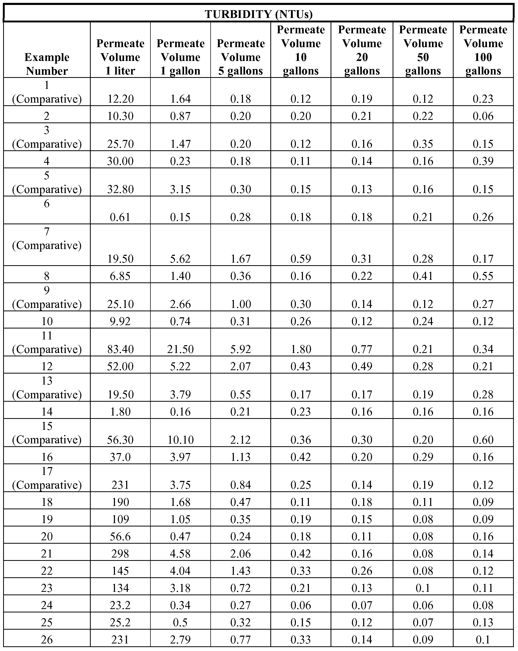

Claims
Priority Applications (5)
| Application Number | Priority Date | Filing Date | Title |
|---|---|---|---|
| US12/810,451 US8512569B2 (en) | 2007-12-31 | 2008-12-15 | Fluid filtration articles and methods of making and using the same |
| BRPI0821499-9A BRPI0821499A2 (en) | 2007-12-31 | 2008-12-15 | Fluid filtration articles and methods of preparation and use thereof |
| JP2010540770A JP5221676B2 (en) | 2007-12-31 | 2008-12-15 | Fluid filtration article and method for making and using the same |
| EP08869800.6A EP2242726B1 (en) | 2007-12-31 | 2008-12-15 | Fluid filtration articles and methods of making and using the same |
| CN2008801274228A CN101952210B (en) | 2007-12-31 | 2008-12-15 | Fluid filtration articles and methods of making and using the same |
Applications Claiming Priority (2)
| Application Number | Priority Date | Filing Date | Title |
|---|---|---|---|
| US1799407P | 2007-12-31 | 2007-12-31 | |
| US61/017,994 | 2007-12-31 |
Publications (1)
| Publication Number | Publication Date |
|---|---|
| WO2009088647A1 true WO2009088647A1 (en) | 2009-07-16 |
Family
ID=40853363
Family Applications (1)
| Application Number | Title | Priority Date | Filing Date |
|---|---|---|---|
| PCT/US2008/086766 WO2009088647A1 (en) | 2007-12-31 | 2008-12-15 | Fluid filtration articles and methods of making and using the same |
Country Status (6)
| Country | Link |
|---|---|
| US (1) | US8512569B2 (en) |
| EP (1) | EP2242726B1 (en) |
| JP (1) | JP5221676B2 (en) |
| CN (1) | CN101952210B (en) |
| BR (1) | BRPI0821499A2 (en) |
| WO (1) | WO2009088647A1 (en) |
Cited By (23)
| Publication number | Priority date | Publication date | Assignee | Title |
|---|---|---|---|---|
| WO2011029568A1 (en) | 2009-09-12 | 2011-03-17 | Hydac Filtertechnik Gmbh | Method for producing a filter element having a filter medium |
| US7985344B2 (en) | 2004-11-05 | 2011-07-26 | Donaldson Company, Inc. | High strength, high capacity filter media and structure |
| US8021455B2 (en) | 2007-02-22 | 2011-09-20 | Donaldson Company, Inc. | Filter element and method |
| US8057567B2 (en) | 2004-11-05 | 2011-11-15 | Donaldson Company, Inc. | Filter medium and breather filter structure |
| US8177875B2 (en) | 2005-02-04 | 2012-05-15 | Donaldson Company, Inc. | Aerosol separator; and method |
| US8267681B2 (en) | 2009-01-28 | 2012-09-18 | Donaldson Company, Inc. | Method and apparatus for forming a fibrous media |
| CN102859060A (en) * | 2010-04-22 | 2013-01-02 | 3M创新有限公司 | Nonwoven nanofiber webs containing chemically active particulates and methods of making and using same |
| US8404014B2 (en) | 2005-02-22 | 2013-03-26 | Donaldson Company, Inc. | Aerosol separator |
| JP2013513474A (en) * | 2009-12-14 | 2013-04-22 | マン ウント フンメル ゲゼルシャフト ミット ベシュレンクテル ハフツング | Compact filter, method for manufacturing a compact filter, and filter medium |
| JP2013528712A (en) * | 2010-04-22 | 2013-07-11 | スリーエム イノベイティブ プロパティズ カンパニー | Nonwoven fiber web containing chemically active particulates and methods of making and using the same |
| CN103214105A (en) * | 2013-04-28 | 2013-07-24 | 沁园集团股份有限公司 | Biomembrane process platy supporter and production method thereof |
| US8584868B2 (en) | 2009-03-17 | 2013-11-19 | Mann+Hummel Gmbh | Filter medium and filter element |
| JP2014500780A (en) * | 2010-09-10 | 2014-01-16 | ゼネラル・エレクトリック・カンパニイ | Cartridge filter including combination of depth filter and submicron filter and RO pretreatment method |
| US9114339B2 (en) | 2007-02-23 | 2015-08-25 | Donaldson Company, Inc. | Formed filter element |
| US9121118B2 (en) | 2011-01-28 | 2015-09-01 | Donaldson Company, Inc. | Method and apparatus for forming a fibrous media |
| US9303339B2 (en) | 2011-01-28 | 2016-04-05 | Donaldson Company, Inc. | Method and apparatus for forming a fibrous media |
| US10179426B2 (en) | 2013-11-06 | 2019-01-15 | Bl Technologies, Inc. | Large format melt-blown depth filter cartridge |
| WO2019202421A1 (en) * | 2018-04-19 | 2019-10-24 | 3M Innovative Properties Company | Biodegradable layered composite |
| USRE47737E1 (en) | 2004-11-05 | 2019-11-26 | Donaldson Company, Inc. | Filter medium and structure |
| WO2021243160A1 (en) * | 2020-05-29 | 2021-12-02 | Hollingsworth & Vose Company | Filter media comprising adsorptive particles |
| US11266936B2 (en) | 2015-04-28 | 2022-03-08 | Bl Technologies, Inc. | Melt-blown depth filter element, method and machine of making it |
| US20230094680A1 (en) * | 2021-09-24 | 2023-03-30 | Linda D. Wilson | Pool strainer basket insect and organic matter trap |
| US11845019B2 (en) | 2013-11-06 | 2023-12-19 | Bl Technologies, Inc. | Large format melt-blown depth filter cartridge |
Families Citing this family (115)
| Publication number | Priority date | Publication date | Assignee | Title |
|---|---|---|---|---|
| US7892993B2 (en) | 2003-06-19 | 2011-02-22 | Eastman Chemical Company | Water-dispersible and multicomponent fibers from sulfopolyesters |
| US8513147B2 (en) | 2003-06-19 | 2013-08-20 | Eastman Chemical Company | Nonwovens produced from multicomponent fibers |
| US20040260034A1 (en) | 2003-06-19 | 2004-12-23 | Haile William Alston | Water-dispersible fibers and fibrous articles |
| US8986432B2 (en) | 2007-11-09 | 2015-03-24 | Hollingsworth & Vose Company | Meltblown filter medium, related applications and uses |
| US8608817B2 (en) | 2007-11-09 | 2013-12-17 | Hollingsworth & Vose Company | Meltblown filter medium |
| CA2702758C (en) * | 2007-11-12 | 2016-08-30 | Exxonmobil Upstream Research Company | Methods of generating and utilizing utility gas |
| CN101952210B (en) * | 2007-12-31 | 2013-05-29 | 3M创新有限公司 | Fluid filtration articles and methods of making and using the same |
| EP2276550A4 (en) | 2008-04-30 | 2012-02-29 | Exxonmobil Upstream Res Co | Method and apparatus for removal of oil from utility gas stream |
| US8357220B2 (en) * | 2008-11-07 | 2013-01-22 | Hollingsworth & Vose Company | Multi-phase filter medium |
| US20100144228A1 (en) * | 2008-12-09 | 2010-06-10 | Branham Kelly D | Nanofibers Having Embedded Particles |
| US8206481B2 (en) * | 2009-02-27 | 2012-06-26 | Bha Group, Inc. | HEPA (H-10) performance synthetic nonwoven and nanofiber composite filter media |
| US8950587B2 (en) | 2009-04-03 | 2015-02-10 | Hollingsworth & Vose Company | Filter media suitable for hydraulic applications |
| EP2419203B1 (en) | 2009-04-13 | 2020-08-12 | Entegris, Inc. | Porous composite membrane |
| US8512519B2 (en) | 2009-04-24 | 2013-08-20 | Eastman Chemical Company | Sulfopolyesters for paper strength and process |
| US8679218B2 (en) | 2010-04-27 | 2014-03-25 | Hollingsworth & Vose Company | Filter media with a multi-layer structure |
| MY162263A (en) | 2010-05-28 | 2017-05-31 | Exxonmobil Upstream Res Co | Integrated adsorber head and valve design and swing adsorption methods related thereto |
| BR112013004279B1 (en) | 2010-08-23 | 2021-01-05 | Fiberweb Holdings Limited | non-woven weave and fibers with electret properties, their manufacturing processes and their use |
| US9273417B2 (en) | 2010-10-21 | 2016-03-01 | Eastman Chemical Company | Wet-Laid process to produce a bound nonwoven article |
| TWI495501B (en) | 2010-11-15 | 2015-08-11 | Exxonmobil Upstream Res Co | Kinetic fractionators, and cycling processes for fractionation of gas mixtures |
| US20120152821A1 (en) | 2010-12-17 | 2012-06-21 | Hollingsworth & Vose Company | Fine fiber filter media and processes |
| US10155186B2 (en) | 2010-12-17 | 2018-12-18 | Hollingsworth & Vose Company | Fine fiber filter media and processes |
| WO2012118757A1 (en) | 2011-03-01 | 2012-09-07 | Exxonmobil Upstream Research Company | Apparatus and systems having a reciprocating valve head assembly and swing adsorption processes related thereto |
| CA2824986C (en) | 2011-03-01 | 2017-05-09 | Exxonmobil Upstream Research Company | Apparatus and systems having an encased adsorbent contactor and swing adsorption processes related thereto |
| WO2012161828A1 (en) | 2011-03-01 | 2012-11-29 | Exxonmobil Upstream Research Company | Apparatus and systems having a rotary valve assembly and swing adsorption processes related thereto |
| JP5882597B2 (en) * | 2011-04-15 | 2016-03-09 | 国立大学法人信州大学 | Filter and filter manufacturing method |
| JP5964412B2 (en) * | 2011-05-03 | 2016-08-03 | ユニリーバー・ナームローゼ・ベンノートシヤープ | Production process of molded thermoplastic resin |
| KR101936451B1 (en) * | 2011-05-09 | 2019-01-08 | 엔테그리스, 아이엔씨. | Porous composite membrane including microporous membrane layers and nanofiber layer |
| ES2592530T3 (en) | 2011-06-17 | 2016-11-30 | Fiberweb, Llc | Multi-layer vapor permeable article, substantially waterproof |
| US10369769B2 (en) | 2011-06-23 | 2019-08-06 | Fiberweb, Inc. | Vapor-permeable, substantially water-impermeable multilayer article |
| WO2012177996A2 (en) | 2011-06-23 | 2012-12-27 | Fiberweb, Inc. | Vapor permeable, substantially water impermeable multilayer article |
| WO2012178011A2 (en) | 2011-06-24 | 2012-12-27 | Fiberweb, Inc. | Vapor-permeable, substantially water-impermeable multilayer article |
| CN102500159B (en) * | 2011-11-29 | 2014-01-01 | 无锡格瑞普尔膜科技有限公司 | Preparation method for deep filter medium with adsorption and ion exchange filter characteristics |
| US8906200B2 (en) | 2012-01-31 | 2014-12-09 | Eastman Chemical Company | Processes to produce short cut microfibers |
| CN102641625B (en) * | 2012-04-25 | 2014-12-24 | 广州华创化工材料科技开发有限公司 | Self-cleaning type air filtering material and preparation method thereof |
| CN104582810B (en) * | 2012-06-20 | 2017-04-19 | 霍林斯沃思和沃斯有限公司 | Fine fiber filter media and processes |
| US8900338B2 (en) | 2012-08-07 | 2014-12-02 | Honeywell International Inc. | Accessory cap for a respiratory filter cartridge |
| KR101485002B1 (en) * | 2012-11-01 | 2015-01-21 | 한국산업은행 | Apparatus for filtering exhaust gas of dust collector with ability of mercury removal |
| DE102012025023A1 (en) * | 2012-12-20 | 2014-06-26 | Johns Manville Europe Gmbh | filter media |
| US9303357B2 (en) | 2013-04-19 | 2016-04-05 | Eastman Chemical Company | Paper and nonwoven articles comprising synthetic microfiber binders |
| DE102013008389A1 (en) * | 2013-05-17 | 2014-11-20 | Mann + Hummel Gmbh | Filter element, in particular air filter element, and filter system with a filter element |
| DE102013008392A1 (en) * | 2013-05-17 | 2014-11-20 | Mann + Hummel Gmbh | Air filters for the interior air of cabins of vehicles, agricultural, construction and working machines |
| US9694306B2 (en) | 2013-05-24 | 2017-07-04 | Hollingsworth & Vose Company | Filter media including polymer compositions and blends |
| US20140360146A1 (en) * | 2013-06-10 | 2014-12-11 | Lydall, Inc. | Wet-laid dual-layer air filtration media including a large diameter synthetic polymeric fiber in a top layer thereof |
| CA2920381C (en) * | 2013-07-12 | 2019-01-15 | Kx Technologies Llc | Filter media for gravity filtration applications |
| US9987578B2 (en) | 2013-08-02 | 2018-06-05 | Cummins Filtration Ip, Inc. | Gradient nanofiber filter media |
| KR101619471B1 (en) * | 2013-08-06 | 2016-05-11 | 주식회사 아모그린텍 | Filter Media for Liquid Filter and Method of Manufacturing the Same |
| SG10202006161UA (en) | 2013-08-30 | 2020-07-29 | Emd Millipore Corp | High capacity composite depth filter media with low extractables |
| CN103801153B (en) * | 2013-11-07 | 2015-07-15 | 嘉兴学院 | Completely biodegradable polylactic acid fiber non-woven fabric filtering material |
| US9605126B2 (en) | 2013-12-17 | 2017-03-28 | Eastman Chemical Company | Ultrafiltration process for the recovery of concentrated sulfopolyester dispersion |
| US9598802B2 (en) | 2013-12-17 | 2017-03-21 | Eastman Chemical Company | Ultrafiltration process for producing a sulfopolyester concentrate |
| US10351442B2 (en) | 2013-12-18 | 2019-07-16 | Brita Lp | Flow control device for filter as you pour system |
| US10654725B2 (en) * | 2013-12-18 | 2020-05-19 | Brita Lp | Filter assembly for filter as you pour filtration |
| US10604420B2 (en) | 2013-12-18 | 2020-03-31 | Brita Lp | Method and apparatus for reservoir free and ventless water filtering |
| CA2933185C (en) | 2013-12-18 | 2021-08-17 | Brita Lp | Lid for filter-as-you-pour container system |
| US11066311B2 (en) * | 2013-12-18 | 2021-07-20 | Brita I.P | Method of using a filter media for filtration |
| CN104215751B (en) * | 2014-06-19 | 2016-01-06 | 黄然 | A kind of ion exchange resin Indication of Losing Efficacy coating prepared by PLA |
| AU2015294518B2 (en) | 2014-07-25 | 2019-06-27 | Exxonmobil Upstream Research Company | Apparatus and system having a valve assembly and swing adsorption processes related thereto |
| US20170217125A1 (en) * | 2014-09-11 | 2017-08-03 | Agency For Science, Technology And Research | Electrospun conductive carbon fibers |
| US20160074789A1 (en) * | 2014-09-11 | 2016-03-17 | Donaldson Company, Inc. | Filtration media, media pack assemblies, and methods |
| CN105582745A (en) * | 2014-10-24 | 2016-05-18 | 张家港骏马无纺布有限公司 | Superfine-fiber filtering material and preparation method therefor |
| WO2016076994A1 (en) | 2014-11-11 | 2016-05-19 | Exxonmobil Upstream Research Company | High capacity structures and monoliths via paste imprinting |
| CA2970286C (en) | 2014-12-10 | 2019-08-13 | Exxonmobil Research And Engineering Company | Adsorbent-incorporated polymer fibers in packed bed and fabric contactors, and methods and devices using same |
| EP3237091B1 (en) | 2014-12-23 | 2021-08-04 | ExxonMobil Upstream Research Company | Structured adsorbent beds and methods of producing the same |
| WO2016186725A1 (en) | 2015-05-15 | 2016-11-24 | Exxonmobil Upstream Research Company | Apparatus and system for swing adsorption processes related thereto comprising mid-bed purge systems |
| CA2979870C (en) | 2015-05-15 | 2019-12-03 | Exxonmobil Upstream Research Company | Apparatus and system for swing adsorption processes related thereto |
| US10427951B2 (en) | 2015-08-20 | 2019-10-01 | Brita Lp | Water purification filter and system |
| US10220345B2 (en) | 2015-09-02 | 2019-03-05 | Exxonmobil Upstream Research Company | Apparatus and system for swing adsorption processes related thereto |
| US10080991B2 (en) | 2015-09-02 | 2018-09-25 | Exxonmobil Upstream Research Company | Apparatus and system for swing adsorption processes related thereto |
| WO2017055918A1 (en) | 2015-09-30 | 2017-04-06 | Brita Lp | Filter core configuration |
| AU2016332961A1 (en) | 2015-09-30 | 2018-04-05 | Brita Lp | Filter cartridge placement in filter as you pour system |
| CA3000310C (en) | 2015-09-30 | 2023-02-28 | Brita Lp | Filter design with interchangeable core cover |
| CA3001336A1 (en) | 2015-10-27 | 2017-05-04 | Exxonmobil Upstream Research Company | Apparatus and system for swing adsorption processes related thereto having a plurality of valves |
| CA3003169A1 (en) | 2015-10-27 | 2017-05-04 | Exxonmobil Upstream Research Company | Apparatus and system for swing adsorption processes related thereto having actively-controlled feed poppet valves and passively controlled product valves |
| US10040022B2 (en) | 2015-10-27 | 2018-08-07 | Exxonmobil Upstream Research Company | Apparatus and system for swing adsorption processes related thereto |
| CA3005448A1 (en) | 2015-11-16 | 2017-05-26 | Exxonmobil Upstream Research Company | Adsorbent materials and methods of adsorbing carbon dioxide |
| US10252200B2 (en) | 2016-02-17 | 2019-04-09 | Hollingsworth & Vose Company | Filter media including a filtration layer comprising synthetic fibers |
| US11014030B2 (en) | 2016-02-17 | 2021-05-25 | Hollingsworth & Vose Company | Filter media including flame retardant fibers |
| CN108883358B (en) | 2016-03-18 | 2021-06-08 | 埃克森美孚上游研究公司 | Apparatus and system for swing adsorption process associated therewith |
| JP2017185422A (en) * | 2016-04-01 | 2017-10-12 | Jnc株式会社 | Depth filter |
| DE112017002064T5 (en) * | 2016-04-18 | 2018-12-27 | Cummins Filtration Ip, Inc. | NANOFIBER FILTER MEDIA FOR HIGH-PERFORMANCE APPLICATIONS |
| EP3463620A1 (en) | 2016-05-31 | 2019-04-10 | ExxonMobil Upstream Research Company | Apparatus and system for swing adsorption processes |
| EP3463619A1 (en) | 2016-05-31 | 2019-04-10 | ExxonMobil Upstream Research Company | Apparatus and system for swing adsorption processes |
| US10668411B2 (en) * | 2016-07-20 | 2020-06-02 | Entegris, Inc. | Depth filtration media with multiple organic and/or inorganic materials |
| CN106367893A (en) * | 2016-08-30 | 2017-02-01 | 山东胜伟园林科技有限公司 | Bio-degradable non-woven fabric material and preparation method thereof |
| US10434458B2 (en) | 2016-08-31 | 2019-10-08 | Exxonmobil Upstream Research Company | Apparatus and system for swing adsorption processes related thereto |
| AU2017320837B2 (en) | 2016-09-01 | 2020-07-23 | Exxonmobil Upstream Research Company | Swing adsorption processes for removing water using 3A zeolite structures |
| US10328382B2 (en) | 2016-09-29 | 2019-06-25 | Exxonmobil Upstream Research Company | Apparatus and system for testing swing adsorption processes |
| US10898838B2 (en) | 2016-12-15 | 2021-01-26 | Hollingsworth & Vose Company | Filter media including adhesives |
| US10543441B2 (en) | 2016-12-15 | 2020-01-28 | Hollingsworth & Vose Company | Filter media including adhesives and/or oleophobic properties |
| US10549230B2 (en) | 2016-12-21 | 2020-02-04 | Exxonmobil Upstream Research Company | Self-supporting structures having active materials |
| RU2720940C1 (en) | 2016-12-21 | 2020-05-14 | Эксонмобил Апстрим Рисерч Компани | Self-supported structures having active materials |
| US11547963B2 (en) | 2017-03-29 | 2023-01-10 | Knowlton Technologies, Llc | High efficiency synthetic filter media |
| DE102018100935A1 (en) * | 2017-11-28 | 2019-05-29 | BLüCHER GMBH | Air-permeable surface filter material and its use |
| US11583797B2 (en) * | 2018-01-04 | 2023-02-21 | Nxtnano, Llc | Dual density nanofiber media |
| US11331620B2 (en) | 2018-01-24 | 2022-05-17 | Exxonmobil Upstream Research Company | Apparatus and system for swing adsorption processes |
| WO2019168628A1 (en) | 2018-02-28 | 2019-09-06 | Exxonmobil Upstream Research Company | Apparatus and system for swing adsorption processes |
| US11207863B2 (en) | 2018-12-12 | 2021-12-28 | Owens Corning Intellectual Capital, Llc | Acoustic insulator |
| US11666199B2 (en) | 2018-12-12 | 2023-06-06 | Owens Corning Intellectual Capital, Llc | Appliance with cellulose-based insulator |
| US11318410B2 (en) | 2018-12-21 | 2022-05-03 | Exxonmobil Upstream Research Company | Flow modulation systems, apparatus, and methods for cyclical swing adsorption |
| WO2020174951A1 (en) * | 2019-02-28 | 2020-09-03 | 富士フイルム株式会社 | Filter for liquids, and method for manufacturing filter for liquids |
| CN109957846B (en) * | 2019-04-08 | 2021-05-14 | 嘉兴学院 | Wide-diameter distribution nanofiber based on coaxial electrostatic spinning and preparation method thereof |
| EP3962641A1 (en) | 2019-04-30 | 2022-03-09 | Exxonmobil Upstream Research Company (EMHC-N1-4A-607) | Rapid cycle adsorbent bed |
| WO2021071755A1 (en) | 2019-10-07 | 2021-04-15 | Exxonmobil Upstream Research Company | Adsorption processes and systems utilizing step lift control of hydraulically actuated poppet valves |
| US20220387915A1 (en) * | 2019-10-08 | 2022-12-08 | Donaldson Company, Inc. | Filter media layers including mixed diameter fine fibers |
| EP4045173A1 (en) | 2019-10-16 | 2022-08-24 | Exxonmobil Upstream Research Company (EMHC-N1-4A-607) | Dehydration processes utilizing cationic zeolite rho |
| CN110563213B (en) * | 2019-10-22 | 2021-02-05 | 河北和悦环保科技有限公司 | Industrial wastewater zero discharge process |
| WO2021124037A1 (en) * | 2019-12-17 | 2021-06-24 | 3M Innovative Properties Company | Filter having multiple denier fibers |
| CN111472097B (en) * | 2020-04-09 | 2021-05-14 | 嘉兴市凯邦锦纶科技股份有限公司 | Melt-blown strand preparation device and preparation method thereof |
| CN112121760B (en) * | 2020-08-21 | 2023-02-10 | 浙江农林大学 | Preparation method of indoor landscape model building material |
| CN114433244A (en) * | 2020-11-06 | 2022-05-06 | 佛山市顺德区美的电热电器制造有限公司 | Filtering membrane for catalyzing and degrading formaldehyde, preparation method and air purification device |
| CN114602245A (en) * | 2020-12-09 | 2022-06-10 | 3M创新有限公司 | Laminated sheet for water filtration, cylindrical filter element, and filter kit |
| WO2023044010A2 (en) * | 2021-09-17 | 2023-03-23 | Ecs Environmental Solutions | Fluid filtration media and applications thereof |
| CN114452717A (en) * | 2022-01-29 | 2022-05-10 | 杭州科百特过滤器材有限公司 | Deep layer filtering medium and preparation method thereof |
| WO2024038421A1 (en) * | 2022-08-19 | 2024-02-22 | Ahlstrom Oyj | Filter media comprising adsorbent |
| CN115262094A (en) * | 2022-09-06 | 2022-11-01 | 桐乡市健民过滤材料有限公司 | High-capacity carbon water filter element composite material and preparation method thereof |
Citations (33)
| Publication number | Priority date | Publication date | Assignee | Title |
|---|---|---|---|---|
| US1723007A (en) | 1927-06-16 | 1929-08-06 | Nat Mfg Co | Door-bolt fixture |
| US1975504A (en) | 1929-12-07 | 1934-10-02 | Richard Schreiber Gastell | Process and apparatus for preparing artificial threads |
| US3874886A (en) | 1973-03-30 | 1975-04-01 | Saint Gobain | Fiber toration; method, equipment and product |
| US4118531A (en) | 1976-08-02 | 1978-10-03 | Minnesota Mining And Manufacturing Company | Web of blended microfibers and crimped bulking fibers |
| US4363646A (en) | 1979-07-20 | 1982-12-14 | Torobin Leonard B | Method and apparatus for producing microfilaments |
| US4536361A (en) | 1978-08-28 | 1985-08-20 | Torobin Leonard B | Method for producing plastic microfilaments |
| US4729371A (en) | 1983-10-11 | 1988-03-08 | Minnesota Mining And Manufacturing Company | Respirator comprised of blown bicomponent fibers |
| US5227107A (en) | 1990-08-07 | 1993-07-13 | Kimberly-Clark Corporation | Process and apparatus for forming nonwovens within a forming chamber |
| US5332426A (en) | 1992-07-29 | 1994-07-26 | Minnesota Mining And Manufacturing Company | Agglomerated activated carbon air filter |
| US5415779A (en) * | 1991-10-11 | 1995-05-16 | Minnesota Mining And Manufacturing Company | Particle-loaded nonwoven fibrous article for separations and purifications |
| US5605746A (en) | 1992-11-18 | 1997-02-25 | Hoechst Celanese Corporation | Fibrous structures containing particulate and including microfiber web |
| US5855788A (en) * | 1996-02-07 | 1999-01-05 | Kimberly-Clark Worldwide, Inc. | Chemically charged-modified filter for removing particles from a liquid and method thereof |
| US6114017A (en) | 1997-07-23 | 2000-09-05 | Fabbricante; Anthony S. | Micro-denier nonwoven materials made using modular die units |
| US6183670B1 (en) | 1997-09-23 | 2001-02-06 | Leonard Torobin | Method and apparatus for producing high efficiency fibrous media incorporating discontinuous sub-micron diameter fibers, and web media formed thereby |
| DE19929709C2 (en) | 1999-06-24 | 2001-07-12 | Lueder Gerking | Process for the production of essentially endless fine threads and use of the device for carrying out the process |
| US6269513B1 (en) | 1998-08-28 | 2001-08-07 | Leonard B. Torobin | Wipe pads with superior solids removal ability using sub-micron filaments |
| US6315806B1 (en) | 1997-09-23 | 2001-11-13 | Leonard Torobin | Method and apparatus for producing high efficiency fibrous media incorporating discontinuous sub-micron diameter fibers, and web media formed thereby |
| US6382526B1 (en) | 1998-10-01 | 2002-05-07 | The University Of Akron | Process and apparatus for the production of nanofibers |
| US6494974B2 (en) | 1999-10-15 | 2002-12-17 | Kimberly-Clark Worldwide, Inc. | Method of forming meltblown webs containing particles |
| US6550622B2 (en) * | 1998-08-27 | 2003-04-22 | Koslow Technologies Corporation | Composite filter medium and fluid filters containing same |
| US20040035095A1 (en) | 1999-10-29 | 2004-02-26 | Hollingsworth & Vose Company | Filter media |
| US6743273B2 (en) | 2000-09-05 | 2004-06-01 | Donaldson Company, Inc. | Polymer, polymer microfiber, polymer nanofiber and applications including filter structures |
| US6861025B2 (en) | 2002-06-20 | 2005-03-01 | 3M Innovative Properties Company | Attenuating fluid manifold for meltblowing die |
| US6872311B2 (en) | 2002-01-31 | 2005-03-29 | Koslow Technologies Corporation | Nanofiber filter media |
| US20050266760A1 (en) | 2003-06-30 | 2005-12-01 | The Procter & Gamble Company | Particulates in nanofiber webs |
| US20050287891A1 (en) | 2004-06-09 | 2005-12-29 | Park David B | Composite material of continuous fiber and ultra high molecular weight polyethylene |
| DE102004046669A1 (en) | 2004-09-24 | 2006-03-30 | Vorwerk & Co. Interholding Gmbh | Method for producing a filter layer and filter layer, in particular for a dust filter bag of a vacuum cleaner |
| US20060096911A1 (en) | 2004-11-08 | 2006-05-11 | Brey Larry A | Particle-containing fibrous web |
| WO2007001990A2 (en) | 2005-06-20 | 2007-01-04 | Polymer Group, Inc. | Apparatus and die cartridge assembly adapted for use therewith, and process for producing fibrous materials |
| US20070062887A1 (en) | 2005-09-20 | 2007-03-22 | Schwandt Brian W | Space optimized coalescer |
| US20080026659A1 (en) | 2006-07-31 | 2008-01-31 | 3M Innovative Properties Company | Monocomponent Monolayer Meltblown Web And Meltblowing Apparatus |
| US20080038976A1 (en) | 2006-07-31 | 2008-02-14 | Berrigan Michael R | Bonded nonwoven fibrous webs comprising softenable oriented semicrystalline polymeric fibers and apparatus and methods for preparing such webs |
| WO2008085545A2 (en) | 2006-07-31 | 2008-07-17 | 3M Innovative Properties Company | Method for making shaped filtration articles |
Family Cites Families (40)
| Publication number | Priority date | Publication date | Assignee | Title |
|---|---|---|---|---|
| US3323963A (en) * | 1964-01-08 | 1967-06-06 | Mine Safety Appliances Co | Method of making filter coil |
| GB1522605A (en) * | 1974-09-26 | 1978-08-23 | Ici Ltd | Preparation of fibrous sheet product |
| US4666763A (en) * | 1984-12-07 | 1987-05-19 | Akzona Incorporated | Fiber batts and the method of making |
| US4818585A (en) * | 1987-08-24 | 1989-04-04 | Kimberly-Clark Corporation | Agricultural protective fabric |
| DE3731575A1 (en) * | 1987-09-19 | 1989-03-30 | Freudenberg Carl Fa | FILTER PACK |
| US4988560A (en) * | 1987-12-21 | 1991-01-29 | Minnesota Mining And Manufacturing Company | Oriented melt-blown fibers, processes for making such fibers, and webs made from such fibers |
| US4910064A (en) * | 1988-05-25 | 1990-03-20 | Sabee Reinhardt N | Stabilized continuous filament web |
| US5306534A (en) * | 1991-03-22 | 1994-04-26 | Home Care Industries, Inc. | Vacuum cleaner bag with electrostatically charged meltblown layer |
| JPH0624712U (en) * | 1991-04-24 | 1994-04-05 | 大和紡績株式会社 | Cartridge filter |
| US5753343A (en) * | 1992-08-04 | 1998-05-19 | Minnesota Mining And Manufacturing Company | Corrugated nonwoven webs of polymeric microfiber |
| ES2128590T3 (en) * | 1993-08-17 | 1999-05-16 | Minnesota Mining & Mfg | METHOD FOR LOADING FILTERS WITH ELECTRETES. |
| US6171684B1 (en) * | 1995-11-17 | 2001-01-09 | Donaldson Company, Inc. | Filter material construction and method |
| US5871836A (en) * | 1997-08-27 | 1999-02-16 | Airflo Europe N.V. | Composite pleated fibrous structures containing split film fibers |
| US6139308A (en) * | 1998-10-28 | 2000-10-31 | 3M Innovative Properties Company | Uniform meltblown fibrous web and methods and apparatus for manufacturing |
| TW479087B (en) | 1998-11-13 | 2002-03-11 | Kimberly Clark Co | Pulp-modified bicomponent continuous filament nonwoven webs and articles |
| US6846548B2 (en) * | 1999-02-19 | 2005-01-25 | Honeywell International Inc. | Flexible fabric from fibrous web and discontinuous domain matrix |
| US6607624B2 (en) * | 2000-11-20 | 2003-08-19 | 3M Innovative Properties Company | Fiber-forming process |
| BR0115488A (en) * | 2000-11-20 | 2004-02-17 | 3M Innovative Properties Co | Fiber making method, fiber forming apparatus, and non-woven fabric |
| US20030203696A1 (en) * | 2002-04-30 | 2003-10-30 | Healey David Thomas | High efficiency ashrae filter media |
| US20040038014A1 (en) * | 2002-08-20 | 2004-02-26 | Donaldson Company, Inc. | Fiber containing filter media |
| WO2004027135A2 (en) * | 2002-09-19 | 2004-04-01 | Polymer Group, Inc. | Nonwoven industrial fabrics with improved barrier properties |
| US20040092185A1 (en) * | 2002-11-13 | 2004-05-13 | Grafe Timothy H. | Wipe material with nanofiber layer |
| US7476632B2 (en) * | 2002-11-15 | 2009-01-13 | 3M Innovative Properties Company | Fibrous nonwoven web |
| WO2005034659A2 (en) * | 2003-08-11 | 2005-04-21 | University Of Tennessee Research Foundation | Fluorochemical electret treatment for barrier fabrics |
| US6997327B2 (en) * | 2003-09-24 | 2006-02-14 | Velcon Filters, Inc. | Salt-tolerant, water absorbing filter |
| US20050090173A1 (en) * | 2003-10-24 | 2005-04-28 | The Procter & Gamble Company | Nonwoven materials comprising low density fibers and absorbent articles comprising such fibers |
| US6858297B1 (en) * | 2004-04-05 | 2005-02-22 | 3M Innovative Properties Company | Aligned fiber web |
| JP2006069141A (en) * | 2004-09-06 | 2006-03-16 | Teijin Techno Products Ltd | Composite fiber structure and its manufacturing method |
| US20060096910A1 (en) * | 2004-11-10 | 2006-05-11 | Brownstein Jerry M | Hybrid fabric filtration device |
| US8092566B2 (en) * | 2004-12-28 | 2012-01-10 | E.I. Du Pont De Nemours And Company | Filtration media for filtering particulate material from gas streams |
| US7717975B2 (en) * | 2005-02-16 | 2010-05-18 | Donaldson Company, Inc. | Reduced solidity web comprising fiber and fiber spacer or separation means |
| JP4657782B2 (en) | 2005-04-07 | 2011-03-23 | 帝人テクノプロダクツ株式会社 | A filter that combines high collection efficiency and low pressure loss |
| JP4745815B2 (en) * | 2005-12-20 | 2011-08-10 | 帝人テクノプロダクツ株式会社 | Air filter material for internal combustion engines |
| US7938276B2 (en) * | 2006-02-01 | 2011-05-10 | Mechanical Manufacturing Corporation | Filtration architecture for optimized performance |
| EP2377594A1 (en) * | 2006-02-13 | 2011-10-19 | Donaldson Company, Inc. | Filter web comprising nanofibers and bioactive particulates |
| US7696109B2 (en) * | 2006-02-24 | 2010-04-13 | The Clorox Company | Low-density cleaning substrate |
| US7947142B2 (en) * | 2006-07-31 | 2011-05-24 | 3M Innovative Properties Company | Pleated filter with monolayer monocomponent meltspun media |
| WO2009088648A1 (en) * | 2007-12-31 | 2009-07-16 | 3M Innovative Properties Company | Composite non-woven fibrous webs having continuous particulate phase and methods of making and using the same |
| CN101952210B (en) * | 2007-12-31 | 2013-05-29 | 3M创新有限公司 | Fluid filtration articles and methods of making and using the same |
| WO2011028661A2 (en) * | 2009-09-01 | 2011-03-10 | 3M Innovative Properties Company | Apparatus, system, and method for forming nanofibers and nanofiber webs |
-
2008
- 2008-12-15 CN CN2008801274228A patent/CN101952210B/en not_active Expired - Fee Related
- 2008-12-15 WO PCT/US2008/086766 patent/WO2009088647A1/en active Application Filing
- 2008-12-15 JP JP2010540770A patent/JP5221676B2/en not_active Expired - Fee Related
- 2008-12-15 BR BRPI0821499-9A patent/BRPI0821499A2/en not_active IP Right Cessation
- 2008-12-15 EP EP08869800.6A patent/EP2242726B1/en not_active Not-in-force
- 2008-12-15 US US12/810,451 patent/US8512569B2/en active Active
Patent Citations (35)
| Publication number | Priority date | Publication date | Assignee | Title |
|---|---|---|---|---|
| US1723007A (en) | 1927-06-16 | 1929-08-06 | Nat Mfg Co | Door-bolt fixture |
| US1975504A (en) | 1929-12-07 | 1934-10-02 | Richard Schreiber Gastell | Process and apparatus for preparing artificial threads |
| US3874886A (en) | 1973-03-30 | 1975-04-01 | Saint Gobain | Fiber toration; method, equipment and product |
| US4118531A (en) | 1976-08-02 | 1978-10-03 | Minnesota Mining And Manufacturing Company | Web of blended microfibers and crimped bulking fibers |
| US4536361A (en) | 1978-08-28 | 1985-08-20 | Torobin Leonard B | Method for producing plastic microfilaments |
| US4363646A (en) | 1979-07-20 | 1982-12-14 | Torobin Leonard B | Method and apparatus for producing microfilaments |
| US6057256A (en) | 1983-10-11 | 2000-05-02 | 3M Innovative Properties Company | Web of biocomponent blown fibers |
| US4729371A (en) | 1983-10-11 | 1988-03-08 | Minnesota Mining And Manufacturing Company | Respirator comprised of blown bicomponent fibers |
| US5227107A (en) | 1990-08-07 | 1993-07-13 | Kimberly-Clark Corporation | Process and apparatus for forming nonwovens within a forming chamber |
| US5415779A (en) * | 1991-10-11 | 1995-05-16 | Minnesota Mining And Manufacturing Company | Particle-loaded nonwoven fibrous article for separations and purifications |
| US5332426A (en) | 1992-07-29 | 1994-07-26 | Minnesota Mining And Manufacturing Company | Agglomerated activated carbon air filter |
| US5605746A (en) | 1992-11-18 | 1997-02-25 | Hoechst Celanese Corporation | Fibrous structures containing particulate and including microfiber web |
| US5855788A (en) * | 1996-02-07 | 1999-01-05 | Kimberly-Clark Worldwide, Inc. | Chemically charged-modified filter for removing particles from a liquid and method thereof |
| US6114017A (en) | 1997-07-23 | 2000-09-05 | Fabbricante; Anthony S. | Micro-denier nonwoven materials made using modular die units |
| US6315806B1 (en) | 1997-09-23 | 2001-11-13 | Leonard Torobin | Method and apparatus for producing high efficiency fibrous media incorporating discontinuous sub-micron diameter fibers, and web media formed thereby |
| US6183670B1 (en) | 1997-09-23 | 2001-02-06 | Leonard Torobin | Method and apparatus for producing high efficiency fibrous media incorporating discontinuous sub-micron diameter fibers, and web media formed thereby |
| US6550622B2 (en) * | 1998-08-27 | 2003-04-22 | Koslow Technologies Corporation | Composite filter medium and fluid filters containing same |
| US6269513B1 (en) | 1998-08-28 | 2001-08-07 | Leonard B. Torobin | Wipe pads with superior solids removal ability using sub-micron filaments |
| US6382526B1 (en) | 1998-10-01 | 2002-05-07 | The University Of Akron | Process and apparatus for the production of nanofibers |
| DE19929709C2 (en) | 1999-06-24 | 2001-07-12 | Lueder Gerking | Process for the production of essentially endless fine threads and use of the device for carrying out the process |
| US6800226B1 (en) | 1999-06-24 | 2004-10-05 | Gerking Lueder | Method and device for the production of an essentially continous fine thread |
| US6494974B2 (en) | 1999-10-15 | 2002-12-17 | Kimberly-Clark Worldwide, Inc. | Method of forming meltblown webs containing particles |
| US20040035095A1 (en) | 1999-10-29 | 2004-02-26 | Hollingsworth & Vose Company | Filter media |
| US6743273B2 (en) | 2000-09-05 | 2004-06-01 | Donaldson Company, Inc. | Polymer, polymer microfiber, polymer nanofiber and applications including filter structures |
| US6872311B2 (en) | 2002-01-31 | 2005-03-29 | Koslow Technologies Corporation | Nanofiber filter media |
| US6861025B2 (en) | 2002-06-20 | 2005-03-01 | 3M Innovative Properties Company | Attenuating fluid manifold for meltblowing die |
| US20050266760A1 (en) | 2003-06-30 | 2005-12-01 | The Procter & Gamble Company | Particulates in nanofiber webs |
| US20050287891A1 (en) | 2004-06-09 | 2005-12-29 | Park David B | Composite material of continuous fiber and ultra high molecular weight polyethylene |
| DE102004046669A1 (en) | 2004-09-24 | 2006-03-30 | Vorwerk & Co. Interholding Gmbh | Method for producing a filter layer and filter layer, in particular for a dust filter bag of a vacuum cleaner |
| US20060096911A1 (en) | 2004-11-08 | 2006-05-11 | Brey Larry A | Particle-containing fibrous web |
| WO2007001990A2 (en) | 2005-06-20 | 2007-01-04 | Polymer Group, Inc. | Apparatus and die cartridge assembly adapted for use therewith, and process for producing fibrous materials |
| US20070062887A1 (en) | 2005-09-20 | 2007-03-22 | Schwandt Brian W | Space optimized coalescer |
| US20080026659A1 (en) | 2006-07-31 | 2008-01-31 | 3M Innovative Properties Company | Monocomponent Monolayer Meltblown Web And Meltblowing Apparatus |
| US20080038976A1 (en) | 2006-07-31 | 2008-02-14 | Berrigan Michael R | Bonded nonwoven fibrous webs comprising softenable oriented semicrystalline polymeric fibers and apparatus and methods for preparing such webs |
| WO2008085545A2 (en) | 2006-07-31 | 2008-07-17 | 3M Innovative Properties Company | Method for making shaped filtration articles |
Non-Patent Citations (3)
| Title |
|---|
| DAVIES, C. N.: "The Separation of Airborne Dust and Particles", INSTITUTION OF MECHANICAL ENGINEERS, LONDON PROCEEDINGS, vol. 1B, pages 1952 |
| See also references of EP2242726A4 * |
| ZEHEV TADMOR; COSTAS GOGOS: "Principles of Polymer Processing", 1979, JOHN WILEY AND SONS, pages: 77 - 84 |
Cited By (41)
| Publication number | Priority date | Publication date | Assignee | Title |
|---|---|---|---|---|
| US8268033B2 (en) | 2004-11-05 | 2012-09-18 | Donaldson Company, Inc. | Filter medium and structure |
| US8021457B2 (en) | 2004-11-05 | 2011-09-20 | Donaldson Company, Inc. | Filter media and structure |
| US8641796B2 (en) | 2004-11-05 | 2014-02-04 | Donaldson Company, Inc. | Filter medium and breather filter structure |
| US8512435B2 (en) | 2004-11-05 | 2013-08-20 | Donaldson Company, Inc. | Filter medium and breather filter structure |
| US8277529B2 (en) | 2004-11-05 | 2012-10-02 | Donaldson Company, Inc. | Filter medium and breather filter structure |
| US8057567B2 (en) | 2004-11-05 | 2011-11-15 | Donaldson Company, Inc. | Filter medium and breather filter structure |
| US9795906B2 (en) | 2004-11-05 | 2017-10-24 | Donaldson Company, Inc. | Filter medium and breather filter structure |
| US10610813B2 (en) | 2004-11-05 | 2020-04-07 | Donaldson Company, Inc. | Filter medium and breather filter structure |
| US7985344B2 (en) | 2004-11-05 | 2011-07-26 | Donaldson Company, Inc. | High strength, high capacity filter media and structure |
| US11504663B2 (en) | 2004-11-05 | 2022-11-22 | Donaldson Company, Inc. | Filter medium and breather filter structure |
| USRE49097E1 (en) | 2004-11-05 | 2022-06-07 | Donaldson Company, Inc. | Filter medium and structure |
| USRE47737E1 (en) | 2004-11-05 | 2019-11-26 | Donaldson Company, Inc. | Filter medium and structure |
| US8460424B2 (en) | 2005-02-04 | 2013-06-11 | Donaldson Company, Inc. | Aerosol separator; and method |
| US8177875B2 (en) | 2005-02-04 | 2012-05-15 | Donaldson Company, Inc. | Aerosol separator; and method |
| US8404014B2 (en) | 2005-02-22 | 2013-03-26 | Donaldson Company, Inc. | Aerosol separator |
| US8021455B2 (en) | 2007-02-22 | 2011-09-20 | Donaldson Company, Inc. | Filter element and method |
| US9114339B2 (en) | 2007-02-23 | 2015-08-25 | Donaldson Company, Inc. | Formed filter element |
| US10316468B2 (en) | 2009-01-28 | 2019-06-11 | Donaldson Company, Inc. | Fibrous media |
| US9885154B2 (en) | 2009-01-28 | 2018-02-06 | Donaldson Company, Inc. | Fibrous media |
| US8524041B2 (en) | 2009-01-28 | 2013-09-03 | Donaldson Company, Inc. | Method for forming a fibrous media |
| US8267681B2 (en) | 2009-01-28 | 2012-09-18 | Donaldson Company, Inc. | Method and apparatus for forming a fibrous media |
| US9353481B2 (en) | 2009-01-28 | 2016-05-31 | Donldson Company, Inc. | Method and apparatus for forming a fibrous media |
| US8584868B2 (en) | 2009-03-17 | 2013-11-19 | Mann+Hummel Gmbh | Filter medium and filter element |
| DE102009041401A1 (en) * | 2009-09-12 | 2011-03-24 | Hydac Filtertechnik Gmbh | Filter element with a filter medium and method for producing the same |
| WO2011029568A1 (en) | 2009-09-12 | 2011-03-17 | Hydac Filtertechnik Gmbh | Method for producing a filter element having a filter medium |
| JP2013513474A (en) * | 2009-12-14 | 2013-04-22 | マン ウント フンメル ゲゼルシャフト ミット ベシュレンクテル ハフツング | Compact filter, method for manufacturing a compact filter, and filter medium |
| CN102859060A (en) * | 2010-04-22 | 2013-01-02 | 3M创新有限公司 | Nonwoven nanofiber webs containing chemically active particulates and methods of making and using same |
| US9475034B2 (en) | 2010-04-22 | 2016-10-25 | 3M Innovative Properties Company | Nonwoven fibrous webs containing chemically active particulates and methods of making and using same |
| JP2013528712A (en) * | 2010-04-22 | 2013-07-11 | スリーエム イノベイティブ プロパティズ カンパニー | Nonwoven fiber web containing chemically active particulates and methods of making and using the same |
| JP2014500780A (en) * | 2010-09-10 | 2014-01-16 | ゼネラル・エレクトリック・カンパニイ | Cartridge filter including combination of depth filter and submicron filter and RO pretreatment method |
| US9121118B2 (en) | 2011-01-28 | 2015-09-01 | Donaldson Company, Inc. | Method and apparatus for forming a fibrous media |
| US9303339B2 (en) | 2011-01-28 | 2016-04-05 | Donaldson Company, Inc. | Method and apparatus for forming a fibrous media |
| CN103214105A (en) * | 2013-04-28 | 2013-07-24 | 沁园集团股份有限公司 | Biomembrane process platy supporter and production method thereof |
| CN103214105B (en) * | 2013-04-28 | 2014-09-24 | 沁园集团股份有限公司 | Biomembrane process platy supporter and production method thereof |
| US10179426B2 (en) | 2013-11-06 | 2019-01-15 | Bl Technologies, Inc. | Large format melt-blown depth filter cartridge |
| US11845019B2 (en) | 2013-11-06 | 2023-12-19 | Bl Technologies, Inc. | Large format melt-blown depth filter cartridge |
| US11266936B2 (en) | 2015-04-28 | 2022-03-08 | Bl Technologies, Inc. | Melt-blown depth filter element, method and machine of making it |
| WO2019202421A1 (en) * | 2018-04-19 | 2019-10-24 | 3M Innovative Properties Company | Biodegradable layered composite |
| WO2021243160A1 (en) * | 2020-05-29 | 2021-12-02 | Hollingsworth & Vose Company | Filter media comprising adsorptive particles |
| US20230094680A1 (en) * | 2021-09-24 | 2023-03-30 | Linda D. Wilson | Pool strainer basket insect and organic matter trap |
| US11713584B2 (en) * | 2021-09-24 | 2023-08-01 | Linda D. Wilson | Pool strainer basket insect and organic matter trap |
Also Published As
| Publication number | Publication date |
|---|---|
| CN101952210B (en) | 2013-05-29 |
| EP2242726A1 (en) | 2010-10-27 |
| BRPI0821499A2 (en) | 2015-06-16 |
| JP5221676B2 (en) | 2013-06-26 |
| EP2242726A4 (en) | 2012-09-05 |
| JP2011508665A (en) | 2011-03-17 |
| US20100282682A1 (en) | 2010-11-11 |
| US8512569B2 (en) | 2013-08-20 |
| EP2242726B1 (en) | 2018-08-15 |
| CN101952210A (en) | 2011-01-19 |
Similar Documents
| Publication | Publication Date | Title |
|---|---|---|
| US8512569B2 (en) | Fluid filtration articles and methods of making and using the same | |
| EP2235245B1 (en) | Composite non-woven fibrous webs having continuous particulate phase and methods of making and using the same | |
| EP2561127B1 (en) | Nonwoven nanofiber webs containing chemically active particulates and methods of making and using same | |
| EP2561128B1 (en) | Nonwoven fibrous webs containing chemically active particulates and methods of making and using same | |
| EP2726659B1 (en) | Non-woven electret fibrous webs and methods of making same | |
| EP2259860B1 (en) | Air filtration medium with improved dust loading capacity and improved resistance to high humidity environment | |
| US20130108831A1 (en) | Patterned air-laid nonwoven electret fibrous webs and methods of making and using same | |
| CN110998003A (en) | Semi-continuous filaments comprising crystalline polyolefin and hydrocarbon tackifying resin and process for making same |
Legal Events
| Date | Code | Title | Description |
|---|---|---|---|
| WWE | Wipo information: entry into national phase |
Ref document number: 200880127422.8 Country of ref document: CN |
|
| 121 | Ep: the epo has been informed by wipo that ep was designated in this application |
Ref document number: 08869800 Country of ref document: EP Kind code of ref document: A1 |
|
| WWE | Wipo information: entry into national phase |
Ref document number: 12810451 Country of ref document: US |
|
| WWE | Wipo information: entry into national phase |
Ref document number: 2010540770 Country of ref document: JP |
|
| NENP | Non-entry into the national phase |
Ref country code: DE |
|
| WWE | Wipo information: entry into national phase |
Ref document number: 2008869800 Country of ref document: EP |
|
| ENP | Entry into the national phase |
Ref document number: PI0821499 Country of ref document: BR Kind code of ref document: A2 Effective date: 20100629 |