WO2009021107A1 - Single triphenylene chromophores in phosphorescent light emitting diodes - Google Patents
Single triphenylene chromophores in phosphorescent light emitting diodes Download PDFInfo
- Publication number
- WO2009021107A1 WO2009021107A1 PCT/US2008/072452 US2008072452W WO2009021107A1 WO 2009021107 A1 WO2009021107 A1 WO 2009021107A1 US 2008072452 W US2008072452 W US 2008072452W WO 2009021107 A1 WO2009021107 A1 WO 2009021107A1
- Authority
- WO
- WIPO (PCT)
- Prior art keywords
- compound
- fused aryl
- group
- fused
- triphenylene
- Prior art date
Links
- 0 *c1cc(C2C=C(c(c(-c3cc(-c4cc(*)cc(*)c4)ccc33)c4)ccc4-c4cc(*)cc(*)c4)C3=CC2)cc(*)c1 Chemical compound *c1cc(C2C=C(c(c(-c3cc(-c4cc(*)cc(*)c4)ccc33)c4)ccc4-c4cc(*)cc(*)c4)C3=CC2)cc(*)c1 0.000 description 4
- GTTMOCHHQBVXSI-UHFFFAOYSA-N CC1(C)OS(c2cc(-c3ccccc3)cc(-c3ccccc3)c2)OC1(C)C Chemical compound CC1(C)OS(c2cc(-c3ccccc3)cc(-c3ccccc3)c2)OC1(C)C GTTMOCHHQBVXSI-UHFFFAOYSA-N 0.000 description 2
- GEDOYYDMCZUHNW-UHFFFAOYSA-N Brc1ccc(c2ccccc2c2c3cccc2)c3c1 Chemical compound Brc1ccc(c2ccccc2c2c3cccc2)c3c1 GEDOYYDMCZUHNW-UHFFFAOYSA-N 0.000 description 1
- WNCOMBFTYJGKSL-UHFFFAOYSA-N CC1(C)OB(c2cc(-c3ccc(C)cc3)cc(-c3ccc(C)cc3)c2)OC1(C)C Chemical compound CC1(C)OB(c2cc(-c3ccc(C)cc3)cc(-c3ccc(C)cc3)c2)OC1(C)C WNCOMBFTYJGKSL-UHFFFAOYSA-N 0.000 description 1
- KXIFXZJZTKQHDW-UHFFFAOYSA-N COc1cccc(-c(cc2)cc3c2c2ccccc2c2ccccc32)c1 Chemical compound COc1cccc(-c(cc2)cc3c2c2ccccc2c2ccccc32)c1 KXIFXZJZTKQHDW-UHFFFAOYSA-N 0.000 description 1
- MKABPINANIMDHA-UHFFFAOYSA-N c(cc1)ccc1-c1cc(-c2ccccc2)cc(-c2cccc(-c(cc3)cc4c3c3ccccc3c3ccccc43)c2)c1 Chemical compound c(cc1)ccc1-c1cc(-c2ccccc2)cc(-c2cccc(-c(cc3)cc4c3c3ccccc3c3ccccc43)c2)c1 MKABPINANIMDHA-UHFFFAOYSA-N 0.000 description 1
- SLGBZMMZGDRARJ-UHFFFAOYSA-N c1ccc2c3ccccc3c3ccccc3c2c1 Chemical compound c1ccc2c3ccccc3c3ccccc3c2c1 SLGBZMMZGDRARJ-UHFFFAOYSA-N 0.000 description 1
Classifications
-
- H—ELECTRICITY
- H10—SEMICONDUCTOR DEVICES; ELECTRIC SOLID-STATE DEVICES NOT OTHERWISE PROVIDED FOR
- H10K—ORGANIC ELECTRIC SOLID-STATE DEVICES
- H10K85/00—Organic materials used in the body or electrodes of devices covered by this subclass
- H10K85/60—Organic compounds having low molecular weight
- H10K85/615—Polycyclic condensed aromatic hydrocarbons, e.g. anthracene
- H10K85/622—Polycyclic condensed aromatic hydrocarbons, e.g. anthracene containing four rings, e.g. pyrene
-
- C—CHEMISTRY; METALLURGY
- C07—ORGANIC CHEMISTRY
- C07C—ACYCLIC OR CARBOCYCLIC COMPOUNDS
- C07C15/00—Cyclic hydrocarbons containing only six-membered aromatic rings as cyclic parts
- C07C15/20—Polycyclic condensed hydrocarbons
- C07C15/38—Polycyclic condensed hydrocarbons containing four rings
-
- C—CHEMISTRY; METALLURGY
- C07—ORGANIC CHEMISTRY
- C07D—HETEROCYCLIC COMPOUNDS
- C07D307/00—Heterocyclic compounds containing five-membered rings having one oxygen atom as the only ring hetero atom
- C07D307/77—Heterocyclic compounds containing five-membered rings having one oxygen atom as the only ring hetero atom ortho- or peri-condensed with carbocyclic rings or ring systems
- C07D307/91—Dibenzofurans; Hydrogenated dibenzofurans
-
- C—CHEMISTRY; METALLURGY
- C07—ORGANIC CHEMISTRY
- C07D—HETEROCYCLIC COMPOUNDS
- C07D333/00—Heterocyclic compounds containing five-membered rings having one sulfur atom as the only ring hetero atom
- C07D333/50—Heterocyclic compounds containing five-membered rings having one sulfur atom as the only ring hetero atom condensed with carbocyclic rings or ring systems
- C07D333/76—Dibenzothiophenes
-
- C—CHEMISTRY; METALLURGY
- C07—ORGANIC CHEMISTRY
- C07D—HETEROCYCLIC COMPOUNDS
- C07D409/00—Heterocyclic compounds containing two or more hetero rings, at least one ring having sulfur atoms as the only ring hetero atoms
- C07D409/02—Heterocyclic compounds containing two or more hetero rings, at least one ring having sulfur atoms as the only ring hetero atoms containing two hetero rings
- C07D409/04—Heterocyclic compounds containing two or more hetero rings, at least one ring having sulfur atoms as the only ring hetero atoms containing two hetero rings directly linked by a ring-member-to-ring-member bond
-
- C—CHEMISTRY; METALLURGY
- C09—DYES; PAINTS; POLISHES; NATURAL RESINS; ADHESIVES; COMPOSITIONS NOT OTHERWISE PROVIDED FOR; APPLICATIONS OF MATERIALS NOT OTHERWISE PROVIDED FOR
- C09B—ORGANIC DYES OR CLOSELY-RELATED COMPOUNDS FOR PRODUCING DYES, e.g. PIGMENTS; MORDANTS; LAKES
- C09B57/00—Other synthetic dyes of known constitution
-
- C—CHEMISTRY; METALLURGY
- C09—DYES; PAINTS; POLISHES; NATURAL RESINS; ADHESIVES; COMPOSITIONS NOT OTHERWISE PROVIDED FOR; APPLICATIONS OF MATERIALS NOT OTHERWISE PROVIDED FOR
- C09K—MATERIALS FOR MISCELLANEOUS APPLICATIONS, NOT PROVIDED FOR ELSEWHERE
- C09K11/00—Luminescent, e.g. electroluminescent, chemiluminescent materials
- C09K11/02—Use of particular materials as binders, particle coatings or suspension media therefor
- C09K11/025—Use of particular materials as binders, particle coatings or suspension media therefor non-luminescent particle coatings or suspension media
-
- C—CHEMISTRY; METALLURGY
- C09—DYES; PAINTS; POLISHES; NATURAL RESINS; ADHESIVES; COMPOSITIONS NOT OTHERWISE PROVIDED FOR; APPLICATIONS OF MATERIALS NOT OTHERWISE PROVIDED FOR
- C09K—MATERIALS FOR MISCELLANEOUS APPLICATIONS, NOT PROVIDED FOR ELSEWHERE
- C09K11/00—Luminescent, e.g. electroluminescent, chemiluminescent materials
- C09K11/06—Luminescent, e.g. electroluminescent, chemiluminescent materials containing organic luminescent materials
-
- H—ELECTRICITY
- H05—ELECTRIC TECHNIQUES NOT OTHERWISE PROVIDED FOR
- H05B—ELECTRIC HEATING; ELECTRIC LIGHT SOURCES NOT OTHERWISE PROVIDED FOR; CIRCUIT ARRANGEMENTS FOR ELECTRIC LIGHT SOURCES, IN GENERAL
- H05B33/00—Electroluminescent light sources
- H05B33/12—Light sources with substantially two-dimensional radiating surfaces
- H05B33/14—Light sources with substantially two-dimensional radiating surfaces characterised by the chemical or physical composition or the arrangement of the electroluminescent material, or by the simultaneous addition of the electroluminescent material in or onto the light source
-
- H—ELECTRICITY
- H10—SEMICONDUCTOR DEVICES; ELECTRIC SOLID-STATE DEVICES NOT OTHERWISE PROVIDED FOR
- H10K—ORGANIC ELECTRIC SOLID-STATE DEVICES
- H10K85/00—Organic materials used in the body or electrodes of devices covered by this subclass
- H10K85/10—Organic polymers or oligomers
- H10K85/141—Organic polymers or oligomers comprising aliphatic or olefinic chains, e.g. poly N-vinylcarbazol, PVC or PTFE
-
- H—ELECTRICITY
- H10—SEMICONDUCTOR DEVICES; ELECTRIC SOLID-STATE DEVICES NOT OTHERWISE PROVIDED FOR
- H10K—ORGANIC ELECTRIC SOLID-STATE DEVICES
- H10K85/00—Organic materials used in the body or electrodes of devices covered by this subclass
- H10K85/30—Coordination compounds
- H10K85/341—Transition metal complexes, e.g. Ru(II)polypyridine complexes
- H10K85/342—Transition metal complexes, e.g. Ru(II)polypyridine complexes comprising iridium
-
- H—ELECTRICITY
- H10—SEMICONDUCTOR DEVICES; ELECTRIC SOLID-STATE DEVICES NOT OTHERWISE PROVIDED FOR
- H10K—ORGANIC ELECTRIC SOLID-STATE DEVICES
- H10K85/00—Organic materials used in the body or electrodes of devices covered by this subclass
- H10K85/60—Organic compounds having low molecular weight
- H10K85/631—Amine compounds having at least two aryl rest on at least one amine-nitrogen atom, e.g. triphenylamine
- H10K85/636—Amine compounds having at least two aryl rest on at least one amine-nitrogen atom, e.g. triphenylamine comprising heteroaromatic hydrocarbons as substituents on the nitrogen atom
-
- C—CHEMISTRY; METALLURGY
- C07—ORGANIC CHEMISTRY
- C07C—ACYCLIC OR CARBOCYCLIC COMPOUNDS
- C07C2603/00—Systems containing at least three condensed rings
- C07C2603/02—Ortho- or ortho- and peri-condensed systems
- C07C2603/40—Ortho- or ortho- and peri-condensed systems containing four condensed rings
- C07C2603/42—Ortho- or ortho- and peri-condensed systems containing four condensed rings containing only six-membered rings
-
- C—CHEMISTRY; METALLURGY
- C09—DYES; PAINTS; POLISHES; NATURAL RESINS; ADHESIVES; COMPOSITIONS NOT OTHERWISE PROVIDED FOR; APPLICATIONS OF MATERIALS NOT OTHERWISE PROVIDED FOR
- C09K—MATERIALS FOR MISCELLANEOUS APPLICATIONS, NOT PROVIDED FOR ELSEWHERE
- C09K2211/00—Chemical nature of organic luminescent or tenebrescent compounds
- C09K2211/10—Non-macromolecular compounds
- C09K2211/1003—Carbocyclic compounds
- C09K2211/1007—Non-condensed systems
-
- C—CHEMISTRY; METALLURGY
- C09—DYES; PAINTS; POLISHES; NATURAL RESINS; ADHESIVES; COMPOSITIONS NOT OTHERWISE PROVIDED FOR; APPLICATIONS OF MATERIALS NOT OTHERWISE PROVIDED FOR
- C09K—MATERIALS FOR MISCELLANEOUS APPLICATIONS, NOT PROVIDED FOR ELSEWHERE
- C09K2211/00—Chemical nature of organic luminescent or tenebrescent compounds
- C09K2211/10—Non-macromolecular compounds
- C09K2211/1003—Carbocyclic compounds
- C09K2211/1011—Condensed systems
-
- H—ELECTRICITY
- H10—SEMICONDUCTOR DEVICES; ELECTRIC SOLID-STATE DEVICES NOT OTHERWISE PROVIDED FOR
- H10K—ORGANIC ELECTRIC SOLID-STATE DEVICES
- H10K2101/00—Properties of the organic materials covered by group H10K85/00
- H10K2101/10—Triplet emission
-
- H—ELECTRICITY
- H10—SEMICONDUCTOR DEVICES; ELECTRIC SOLID-STATE DEVICES NOT OTHERWISE PROVIDED FOR
- H10K—ORGANIC ELECTRIC SOLID-STATE DEVICES
- H10K2101/00—Properties of the organic materials covered by group H10K85/00
- H10K2101/30—Highest occupied molecular orbital [HOMO], lowest unoccupied molecular orbital [LUMO] or Fermi energy values
-
- H—ELECTRICITY
- H10—SEMICONDUCTOR DEVICES; ELECTRIC SOLID-STATE DEVICES NOT OTHERWISE PROVIDED FOR
- H10K—ORGANIC ELECTRIC SOLID-STATE DEVICES
- H10K2101/00—Properties of the organic materials covered by group H10K85/00
- H10K2101/40—Interrelation of parameters between multiple constituent active layers or sublayers, e.g. HOMO values in adjacent layers
-
- H—ELECTRICITY
- H10—SEMICONDUCTOR DEVICES; ELECTRIC SOLID-STATE DEVICES NOT OTHERWISE PROVIDED FOR
- H10K—ORGANIC ELECTRIC SOLID-STATE DEVICES
- H10K50/00—Organic light-emitting devices
- H10K50/10—OLEDs or polymer light-emitting diodes [PLED]
- H10K50/11—OLEDs or polymer light-emitting diodes [PLED] characterised by the electroluminescent [EL] layers
- H10K50/12—OLEDs or polymer light-emitting diodes [PLED] characterised by the electroluminescent [EL] layers comprising dopants
-
- H—ELECTRICITY
- H10—SEMICONDUCTOR DEVICES; ELECTRIC SOLID-STATE DEVICES NOT OTHERWISE PROVIDED FOR
- H10K—ORGANIC ELECTRIC SOLID-STATE DEVICES
- H10K85/00—Organic materials used in the body or electrodes of devices covered by this subclass
- H10K85/30—Coordination compounds
- H10K85/321—Metal complexes comprising a group IIIA element, e.g. Tris (8-hydroxyquinoline) gallium [Gaq3]
- H10K85/324—Metal complexes comprising a group IIIA element, e.g. Tris (8-hydroxyquinoline) gallium [Gaq3] comprising aluminium, e.g. Alq3
-
- H—ELECTRICITY
- H10—SEMICONDUCTOR DEVICES; ELECTRIC SOLID-STATE DEVICES NOT OTHERWISE PROVIDED FOR
- H10K—ORGANIC ELECTRIC SOLID-STATE DEVICES
- H10K85/00—Organic materials used in the body or electrodes of devices covered by this subclass
- H10K85/60—Organic compounds having low molecular weight
- H10K85/631—Amine compounds having at least two aryl rest on at least one amine-nitrogen atom, e.g. triphenylamine
-
- Y—GENERAL TAGGING OF NEW TECHNOLOGICAL DEVELOPMENTS; GENERAL TAGGING OF CROSS-SECTIONAL TECHNOLOGIES SPANNING OVER SEVERAL SECTIONS OF THE IPC; TECHNICAL SUBJECTS COVERED BY FORMER USPC CROSS-REFERENCE ART COLLECTIONS [XRACs] AND DIGESTS
- Y02—TECHNOLOGIES OR APPLICATIONS FOR MITIGATION OR ADAPTATION AGAINST CLIMATE CHANGE
- Y02E—REDUCTION OF GREENHOUSE GAS [GHG] EMISSIONS, RELATED TO ENERGY GENERATION, TRANSMISSION OR DISTRIBUTION
- Y02E10/00—Energy generation through renewable energy sources
- Y02E10/50—Photovoltaic [PV] energy
- Y02E10/549—Organic PV cells
Definitions
- the claimed invention was made by, on behalf of, and/or in connection with one or more of the following parties to a joint university corporation research agreement: Regents of the University of Michigan, Princeton University, The University of Southern California, and the Universal Display Corporation. The agreement was in effect on and before the date the claimed invention was made, and the claimed invention was made as a result of activities undertaken within the scope of the agreement.
- the present invention relates to organic light emitting devices (OLEDs), and specifically to phosphorescent organic materials used in such devices. More specifically, the present invention relates to triphenylene compounds incorporated into OLEDs.
- Opto-electronic devices that make use of organic materials are becoming increasingly desirable for a number of reasons. Many of the materials used to make such devices are relatively inexpensive, so organic opto-electronic devices have the potential for cost advantages over inorganic devices. In addition, the inherent properties of organic materials, such as their flexibility, may make them well suited for particular applications such as fabrication on a flexible substrate. Examples of organic opto-electronic devices include organic light emitting devices (OLEDs), organic phototransistors, organic photovoltaic cells, and organic photodetectors. For OLEDs, the organic materials may have performance advantages over conventional materials. For example, the wavelength at which an organic emissive layer emits light may generally be readily tuned with appropriate dopants.
- OLEDs organic light emitting devices
- the wavelength at which an organic emissive layer emits light may generally be readily tuned with appropriate dopants.
- organic includes polymeric materials as well as small molecule organic materials that may be used to fabricate organic opto-electronic devices.
- Small molecule refers to any organic material that is not a polymer, and "small molecules” may actually be quite large. Small molecules may include repeat units in some circumstances. For example, using a long chain alkyl group as a substituent does not remove a molecule from the "small molecule” class. Small molecules may also be incorporated into polymers, for example as a pendent group on a polymer backbone or as a part of the backbone. Small molecules may also serve as the core moiety of a dendrimer, which consists of a series of chemical shells built on the core moiety.
- the core moiety of a dendrimer may be a fluorescent or phosphorescent small molecule emitter.
- a dendrimer may be a "small molecule," and it is believed that all dendrimers currently used in the field of OLEDs are small molecules.
- a small molecule has a well-defined chemical formula with a single molecular weight, whereas a polymer has a chemical formula and a molecular weight that may vary from molecule to molecule.
- OLEDs make use of thin organic films that emit light when voltage is applied across the device. OLEDs are becoming an increasingly interesting technology for use in applications such as flat panel displays, illumination, and backlighting. Several OLED materials and configurations are described in U.S. Patent Nos. 5,844,363, 6,303,238, and 5,707,745, which are incorporated herein by reference in their entirety.
- OLED devices are generally (but not always) intended to emit light through at least one of the electrodes, and one or more transparent electrodes may be useful in organic optoelectronic devices.
- a transparent electrode material such as indium tin oxide (ITO)
- ITO indium tin oxide
- a transparent top electrode such as disclosed in U.S. Patent Nos. 5,703,436 and 5,707,745, which are incorporated by reference in their entireties, may also be used.
- the top electrode does not need to be transparent, and may be comprised of a thick and reflective metal layer having a high electrical conductivity.
- the bottom electrode may be opaque and / or reflective.
- an electrode does not need to be transparent, using a thicker layer may provide better conductivity, and using a reflective electrode may increase the amount of light emitted through the other electrode, by reflecting light back towards the transparent electrode.
- Fully transparent devices may also be fabricated, where both electrodes are transparent. Side emitting OLEDs may also be fabricated, and one or both electrodes may be opaque or reflective in such devices.
- top means furthest away from the substrate
- bottom means closest to the substrate.
- the bottom electrode is the electrode closest to the substrate, and is generally the first electrode fabricated.
- the bottom electrode has two surfaces, a bottom surface closest to the substrate, and a top surface further away from the substrate.
- a first layer is described as "disposed over” a second layer
- the first layer is disposed further away from substrate.
- a cathode may be described as “disposed over” an anode, even though there are various organic layers in between.
- solution processible means capable of being dissolved, dispersed, or transported in and/or deposited from a liquid medium, either in solution or suspension form.
- a first "Highest Occupied Molecular Orbital” (HOMO) or “Lowest Unoccupied Molecular Orbital” (LUMO) energy level is "greater than” or "higher than” a second HOMO or LUMO energy level if the first energy level is closer to the vacuum energy level.
- IP ionization potentials
- a higher HOMO energy level corresponds to an IP having a smaller absolute value (an IP that is less negative).
- a higher LUMO energy level corresponds to an electron affinity (EA) having a smaller absolute value (an EA that is less negative).
- the LUMO energy level of a material is higher than the HOMO energy level of the same material.
- a "higher” HOMO or LUMO energy level appears closer to the top of such a diagram than a "lower” HOMO or LUMO energy level.
- the present invention is directed to triphenylene compounds useful in phosphorescent organic light emitting diodes.
- Specific examples include multi-aryl-substituted triphenylenes.
- a preferred group of compounds are triphenylenes that are substituted with a non-fused aryl group having one or more meta-substituents, where each meta-substituent is a non-fused aryl group optionally substituted with further substituents selected from the group consisting of non- fused aryl groups and alkyl groups.
- Additional preferred compounds are triphenylenes that are substituted with a non- fused heteroaryl group having one or more meta-substituents, where each meta-substituent is a non- fused aryl or heteroaryl group optionally substituted with further substituents selected from the group consisting of non- fused aryl groups, non- fused heteroaryl groups, and alkyl groups.
- opto-electronic materials containing a single triphenylene chromophore are demonstrated as a useful class of host materials and enhancement layer materials. These compounds have shown long device lifetime as hosts and blockers for devices doped with red and green phosphorescent emissive materials. When used as phosphorescent host materials, single triphenylene containing compounds have demonstrated less redshifting of the dopant emission when compared to a comparative example host that contains two triphenylene chromophores. This optical effect may allow for devices to be fabricated with more saturated color.
- An emissive layer in an organic light emitting device includes a phosphorescent material and a triphenylene compound.
- the triphenylene compound has an energy gap between the HOMO and the LUMO energy levels that is larger than the energy gap between the HOMO and the LUMO energy levels of the phosphorescent material.
- the triphenylene compound in the emissive layer has an energy gap between its HOMO energy level and its LUMO energy level of at least about 1.8 eV.
- the triphenylene compound has a highest occupied molecular orbital that is lower than the highest occupied molecular orbital of the phosphorescent material.
- the triphenylene compound has a lowest unoccupied molecular orbital that is higher than the lowest unoccupied molecular orbital of the phosphorescent material.
- the emissive layer comprises a phosphorescent material and a triphenylene compound wherein the triphenylene compound has the formula:
- each R 1 , R 2 , R 3 , R 4 , Rs, Re, R?, Rs, R9, Rio, Rn and Ri 2 is independently H or a substituent selected from the group consisting of aryl, substituted aryl, heteroaryl, substituted heteroaryl, alkyl, arylkyl heteroalkyl, alkenyl, and alkynyl and wherein the triphenylene compound has at least two substituents.
- the triphenylene compound has a molecular weight of less than 1400.
- At least one of Ri, R 2 , R3, R 4 , R5, R 6 , R 7 , R8, R9, Rio, Rn and Ri 2 is selected from aryl and substituted aryl.
- each ofR 2 , R3, R 6 , R7, Rio, and Rn is selected from aryl and substituted aryl and in yet another embodiment, each of R 2 , R 3 , R 6 , R7, Rio, and Rn is selected from aryl and substituted aryl and R 2 , R 3 , R 6 , R7, Rio, and Rn are all the same.
- R 1 , R 2 , R3 are independently H or aryl groups with the exception of Triphenylene and at least one of Ri, R 2 , R3 is not H.
- R 1 , R 2 , R 3 may also independently be H, aryl groups, or heteroaryl groups with the exception of Triphenylene and at least one of Ri, R 2 , R3 is not H.
- An organic electroluminescent device comprises an anode, a cathode, and an emissive layer comprising a triphenylene material and a phosphorescent material between the anode and the cathode.
- the triphenylene material may have the formula:
- R 1 , R 2 , R 3 are independently H or aryl groups with the exception of Triphenylene and at least one of Ri, R 2 , R 3 is not H.
- R 1 , R 2 , R 3 may also independently be H, aryl groups, or heteroaryl groups with the exception of Triphenylene and at least one of Ri, R 2 , R3 is not H.
- an organic electroluminescent device comprising an anode, a cathode, and an emissive layer between the anode and the cathode, the emissive layer comprising a phosphorescent material and a compound having a repeat unit, the repeat unit containing a triphenylene moiety.
- Fig. 1 shows an organic light emitting device having separate electron transport, hole transport, and emissive layers, as well as other layers.
- Fig. 2 shows an inverted organic light emitting device that does not have a separate electron transport layer.
- FIG. 3 shows the EL spectra for devices 1-6.
- Fig. 4 shows quantum efficiency versus luminance for devices 1-6.
- Fig. 5 shows lifetest data (40 mA/cm ) for devices 2-6.
- Fig. 6 shows the EL spectra for device 7-9.
- Fig. 7 shows quantum efficiency versus luminance for devices 8-9.
- Fig. 8 shows lifetest data (40 mA/cm 2 ) for devices 8-9.
- Fig. 9 shows the 1 H NMR spectra of compound 1.
- Fig. 10 shows the H NMR spectra of compound 2.
- Fig. 11 shows the 1 H NMR spectra of compound 4.
- Fig. 12 shows a single triphenylene chromophore.
- an OLED comprises at least one organic layer disposed between and electrically connected to an anode and a cathode.
- the anode injects holes and the cathode injects electrons into the organic layer(s).
- the injected holes and electrons each migrate toward the oppositely charged electrode.
- an "exciton” which is a localized electron-hole pair having an excited energy state, is formed.
- Light is emitted when the exciton relaxes via a photoemissive mechanism.
- the exciton may be localized on an excimer or an exciplex. Non-radiative mechanisms, such as thermal relaxation, may also occur, but are generally considered undesirable.
- the initial OLEDs used emissive molecules that emitted light from their singlet states ("fluorescence") as disclosed, for example, in U.S. Patent No. 4,769,292, which is incorporated by reference in its entirety. Fluorescent emission generally occurs in a time frame of less than 10 nanoseconds.
- Phosphorescence may be referred to as a "forbidden" transition because the transition requires a change in spin states, and quantum mechanics indicates that such a transition is not favored.
- phosphorescence generally occurs in a time frame exceeding at least 10 nanoseconds, and typically greater than 100 nanoseconds. If the natural radiative lifetime of phosphorescence is too long, triplets may decay by a non-radiative mechanism, such that no light is emitted.
- Organic phosphorescence is also often observed in molecules containing heteroatoms with unshared pairs of electrons at very low temperatures. 2,2'-bipyridine is such a molecule.
- Non-radiative decay mechanisms are typically temperature dependent, such that an organic material that exhibits phosphorescence at liquid nitrogen temperatures typically does not exhibit phosphorescence at room temperature. But, as demonstrated by Baldo, this problem may be addressed by selecting phosphorescent compounds that do phosphoresce at room temperature.
- Representative emissive layers include doped or un- doped phosphorescent organo-metallic materials such as disclosed in U.S. Patent Nos. 6,303,238 and 6,310,360; U.S. Patent Application Publication Nos. 2002-0034656; 2002-0182441; 2003- 0072964; and WO-02/074015.
- the excitons in an OLED are believed to be created in a ratio of about 3:1, i.e., approximately 75% triplets and 25% singlets. See, Adachi et al., "Nearly 100% Internal Phosphorescent Efficiency In An Organic Light Emitting Device," J. Appl. Phys., 90, 5048 (2001), which is incorporated by reference in its entirety.
- singlet excitons may readily transfer their energy to triplet excited states via "intersystem crossing," whereas triplet excitons may not readily transfer their energy to singlet excited states.
- 100% internal quantum efficiency is theoretically possible with phosphorescent OLEDs.
- Phosphorescence may be preceded by a transition from a triplet excited state to an intermediate non-triplet state from which the emissive decay occurs.
- organic molecules coordinated to lanthanide elements often phosphoresce from excited states localized on the lanthanide metal.
- such materials do not phosphoresce directly from a triplet excited state but instead emit from an atomic excited state centered on the lanthanide metal ion.
- the europium diketonate complexes illustrate one group of these types of species.
- Phosphorescence from triplets can be enhanced over fluorescence by confining, preferably through bonding, the organic molecule in close proximity to an atom of high atomic number. This phenomenon, called the heavy atom effect, is created by a mechanism known as spin-orbit coupling. Such a phosphorescent transition may be observed from an excited metal-to-ligand charge transfer (MLCT) state of an organometallic molecule such as tris(2-phenylpyridine)iridium(III).
- MLCT excited metal-to-ligand charge transfer
- triplet energy refers to an energy corresponding to the highest energy feature discernable in the phosphorescence spectrum of a given material.
- the highest energy feature is not necessarily the peak having the greatest intensity in the phosphorescence spectrum, and could, for example, be a local maximum of a clear shoulder on the high energy side of such a peak.
- organometallic as used herein is as generally understood by one of ordinary skill in the art and as given, for example, in “Inorganic Chemistry” (2nd Edition) by Gary L.
- organometallic refers to compounds which have an organic group bonded to a metal through a carbon-metal bond. This class does not include per se coordination compounds, which are substances having only donor bonds from heteroatoms, such as metal complexes of amines, halides, pseudohalides (CN, etc.), and the like. In practice, organometallic compounds generally comprise, in addition to one or more carbon-metal bonds to an organic species, one or more donor bonds from a heteroatom.
- the carbon-metal bond to an organic species refers to a direct bond between a metal and a carbon atom of an organic group, such as phenyl, alkyl, alkenyl, etc., but does not refer to a metal bond to an "inorganic carbon," such as the carbon of CN or CO.
- Figure 1 shows an organic light emitting device 100.
- Device 100 may include a substrate 110, an anode 115, a hole injection layer 120, a hole transport layer 125, an electron blocking layer 130, an emissive layer 135, a hole blocking layer 140, an electron transport layer 145, an electron injection layer 150, a protective layer 155, and a cathode 160.
- Cathode 160 is a compound cathode having a first conductive layer 162 and a second conductive layer 164.
- Device 100 may be fabricated by depositing the layers described, in order.
- Substrate 110 may be any suitable substrate that provides desired structural properties.
- Substrate 110 may be flexible or rigid.
- Substrate 110 may be transparent, translucent or opaque.
- Plastic and glass are examples of preferred rigid substrate materials.
- Plastic and metal foils are examples of preferred flexible substrate materials.
- Substrate 110 may be a semiconductor material in order to facilitate the fabrication of circuitry.
- substrate 110 may be a silicon wafer upon which circuits are fabricated, capable of controlling OLEDs subsequently deposited on the substrate. Other substrates may be used.
- the material and thickness of substrate 110 may be chosen to obtain desired structural and optical properties.
- Anode 115 may be any suitable anode that is sufficiently conductive to transport holes to the organic layers.
- the material of anode 115 preferably has a work function higher than about 4 eV (a "high work function material").
- Preferred anode materials include conductive metal oxides, such as indium tin oxide (ITO) and indium zinc oxide (IZO), aluminum zinc oxide (AlZnO), and metals.
- Anode 115 (and substrate 110) may be sufficiently transparent to create a bottom-emitting device.
- a preferred transparent substrate and anode combination is commercially available ITO (anode) deposited on glass or plastic (substrate).
- a flexible and transparent substrate-anode combination is disclosed in United States Patent Nos.
- Anode 115 may be opaque and / or reflective. A reflective anode 115 may be preferred for some top-emitting devices, to increase the amount of light emitted from the top of the device.
- the material and thickness of anode 115 may be chosen to obtain desired conductive and optical properties. Where anode 115 is transparent, there may be a range of thickness for a particular material that is thick enough to provide the desired conductivity, yet thin enough to provide the desired degree of transparency. Other anode materials and structures may be used.
- Hole transport layer 125 may include a material capable of transporting holes.
- Hole transport layer 130 may be intrinsic (undoped), or doped. Doping may be used to enhance conductivity.
- ⁇ -NPD and TPD are examples of intrinsic hole transport layers.
- An example of a p-doped hole transport layer is m-MTDATA doped with F4-TCNQ at a molar ratio of 50: 1 , as disclosed in United States Patent Application Publication No. 2003-0230980 to Forrest et al, which is incorporated by reference in its entirety. Other hole transport layers may be used.
- Emissive layer 135 may include an organic material capable of emitting light when a current is passed between anode 115 and cathode 160.
- emissive layer 135 contains a phosphorescent emissive material, although fluorescent emissive materials may also be used. Phosphorescent materials are preferred because of the higher luminescent efficiencies associated with such materials.
- Emissive layer 135 may also comprise a host material capable of transporting electrons and / or holes, doped with an emissive material that may trap electrons, holes, and / or excitons, such that excitons relax from the emissive material via a photoemissive mechanism.
- Emissive layer 135 may comprise a single material that combines transport and emissive properties.
- emissive layer 135 may comprise other materials, such as dopants that tune the emission of the emissive material.
- Emissive layer 135 may include a plurality of emissive materials capable of, in combination, emitting a desired spectrum of light. Examples of phosphorescent emissive materials include Ir(ppy) 3 . Examples of fluorescent emissive materials include DCM and DMQA. Examples of host materials in OLEDs include AIq 3 , CBP and mCP. Examples of emissive and host materials in OLEDs are disclosed in U.S. Patent No. 6,303,238 to Thompson et al., which is incorporated by reference in its entirety.
- preferred host materials include triphenylene complexes.
- Triphenylene compounds are useful materials in other applications in OLEDs such as electron transporting materials as described in US US20050025993.
- Emissive material may be included in emissive layer 135 in a number of ways.
- an emissive small molecule may be incorporated into a polymer. This may be accomplished by several ways: by doping the small molecule into the polymer either as a separate and distinct molecular species; or by incorporating the small molecule into the backbone of the polymer, so as to form a co-polymer; or by bonding the small molecule as a pendant group on the polymer.
- Other emissive layer materials and structures may be used.
- a small molecule emissive material may be present as the core of a dendrimer.
- Many useful emissive materials include one or more ligands bound to a metal center.
- a ligand may be referred to as "photoactive” if it contributes directly to the luminescent properties of an organometallic emissive material.
- a "photoactive" ligand may provide, in conjunction with a metal, the energy levels from which and to which an electron moves when a photon is emitted.
- Other ligands may be referred to as "ancillary.”
- Ancillary ligands may modify the photoactive properties of the molecule, for example by shifting the energy levels of a photoactive ligand, but ancillary ligands do not directly provide the energy levels directly involved in light emission.
- a ligand that is photoactive in one molecule may be ancillary in another.
- Electron transport layer 145 may include a material capable of transporting electrons. Electron transport layer 145 may be intrinsic (undoped), or doped. Doping may be used to enhance conductivity. AIq 3 is an example of an intrinsic electron transport layer. An example of an n-doped electron transport layer is BPhen doped with Li at a molar ratio of 1 : 1 , as disclosed in United States Patent Application Publication No. 2003-0230980 to Forrest et al., which is incorporated by reference in its entirety. Other electron transport layers may be used.
- the charge carrying component of the electron transport layer may be selected such that electrons can be efficiently injected from the cathode into the LUMO (Lowest Unoccupied Molecular Orbital) energy level of the electron transport layer.
- the "charge carrying component” is the material responsible for the LUMO energy level that actually transports electrons. This component may be the base material, or it may be a dopant.
- the LUMO energy level of an organic material may be generally characterized by the electron affinity of that material and the relative electron injection efficiency of a cathode may be generally characterized in terms of the work function of the cathode material.
- the preferred properties of an electron transport layer and the adjacent cathode may be specified in terms of the electron affinity of the charge carrying component of the ETL and the work function of the cathode material.
- the work function of the cathode material is preferably not greater than the electron affinity of the charge carrying component of the electron transport layer by more than about 0.75 eV, more preferably, by not more than about 0.5 eV. Similar considerations apply to any layer into which electrons are being injected.
- Cathode 160 may be any suitable material or combination of materials known to the art, such that cathode 160 is capable of conducting electrons and injecting them into the organic layers of device 100.
- Cathode 160 may be transparent or opaque, and may be reflective.
- Metals and metal oxides are examples of suitable cathode materials.
- Cathode 160 may be a single layer, or may have a compound structure.
- Figure 1 shows a compound cathode 160 having a thin metal layer 162 and a thicker conductive metal oxide layer 164.
- preferred materials for the thicker layer 164 include ITO, IZO, and other materials known to the art.
- cathodes including compound cathodes having a thin layer of metal such as Mg: Ag with an overlying transparent, electrically-conductive, sputter-deposited ITO layer.
- the part of cathode 160 that is in contact with the underlying organic layer, whether it is a single layer cathode 160, the thin metal layer 162 of a compound cathode, or some other part, is preferably made of a material having a work function lower than about 4 eV (a "low work function material").
- Other cathode materials and structures may be used.
- Blocking layers may be used to reduce the number of charge carriers (electrons or holes) and / or excitons that leave the emissive layer.
- An electron blocking layer 130 may be disposed between emissive layer 135 and the hole transport layer 125, to block electrons from leaving emissive layer 135 in the direction of hole transport layer 125.
- a hole blocking layer 140 may be disposed between emissive layer 135 and electron transport layer 145, to block holes from leaving emissive layer 135 in the direction of electron transport layer 145.
- Blocking layers may also be used to block excitons from diffusing out of the emissive layer. The theory and use of blocking layers is described in more detail in United States Patent No. 6,097,147 and United States Patent Application Publication No. 2003-0230980 to Forrest et al., which are incorporated by reference in their entireties.
- blocking layer means that the layer provides a barrier that significantly inhibits transport of charge carriers and/or excitons through the device, without suggesting that the layer necessarily completely blocks the charge carriers and/or excitons.
- the presence of such a blocking layer in a device may result in substantially higher efficiencies as compared to a similar device lacking a blocking layer.
- a blocking layer may be used to confine emission to a desired region of an OLED.
- injection layers are comprised of a material that may improve the injection of charge carriers from one layer, such as an electrode or an organic layer, into an adjacent organic layer. Injection layers may also perform a charge transport function.
- hole injection layer 120 may be any layer that improves the injection of holes from anode 115 into hole transport layer 125.
- CuPc is an example of a material that may be used as a hole injection layer from an ITO anode 115, and other anodes.
- electron injection layer 150 may be any layer that improves the injection of electrons into electron transport layer 145.
- LiF / Al is an example of a material that may be used as an electron injection layer into an electron transport layer from an adjacent layer.
- a hole injection layer may comprise a solution deposited material, such as a spin-coated polymer, e.g., PEDOT:PSS, or it may be a vapor deposited small molecule material, e.g., CuPc or MTDATA.
- a hole injection layer may planarize or wet the anode surface so as to provide efficient hole injection from the anode into the hole injecting material.
- a hole injection layer may also have a charge carrying component having HOMO (Highest Occupied Molecular Orbital) energy levels that favorably match up, as defined by their herein-described relative ionization potential (IP) energies, with the adjacent anode layer on one side of the HIL and the hole transporting layer on the opposite side of the HIL.
- the "charge carrying component” is the material responsible for the HOMO energy level that actually transports holes. This component may be the base material of the HIL, or it may be a dopant. Using a doped HIL allows the dopant to be selected for its electrical properties, and the host to be selected for morphological properties such as wetting, flexibility, toughness, etc.
- the charge carrying component of the HIL preferably has an IP not more than about 0.7 eV greater that the IP of the anode material. More preferably, the charge carrying component has an IP not more than about 0.5 eV greater than the anode material. Similar considerations apply to any layer into which holes are being injected.
- HIL materials are further distinguished from conventional hole transporting materials that are typically used in the hole transporting layer of an OLED in that such HIL materials may have a hole conductivity that is substantially less than the hole conductivity of conventional hole transporting materials.
- the thickness of the HIL of the present invention may be thick enough to help planarize or wet the surface of the anode layer.
- an HIL thickness of as little as 10 nm may be acceptable for a very smooth anode surface.
- a thickness for the HIL of up to 50 nm may be desired in some cases.
- a protective layer may be used to protect underlying layers during subsequent fabrication processes.
- the processes used to fabricate metal or metal oxide top electrodes may damage organic layers, and a protective layer may be used to reduce or eliminate such damage.
- protective layer 155 may reduce damage to underlying organic layers during the fabrication of cathode 160.
- a protective layer has a high carrier mobility for the type of carrier that it transports (electrons in device 100), such that it does not significantly increase the operating voltage of device 100.
- CuPc, BCP, and various metal phthalocyanines are examples of materials that may be used in protective layers. Other materials or combinations of materials may be used.
- protective layer 155 is preferably thick enough that there is little or no damage to underlying layers due to fabrication processes that occur after organic protective layer 160 is deposited, yet not so thick as to significantly increase the operating voltage of device 100.
- Protective layer 155 may be doped to increase its conductivity.
- a CuPc or BCP protective layer 160 may be doped with Li.
- Figure 2 shows an inverted OLED 200.
- the device includes a substrate 210, an cathode 215, an emissive layer 220, a hole transport layer 225, and an anode 230.
- Device 200 may be fabricated by depositing the layers described, in order. Because the most common OLED configuration has a cathode disposed over the anode, and device 200 has cathode 215 disposed under anode 230, device 200 may be referred to as an "inverted" OLED. Materials similar to those described with respect to device 100 may be used in the corresponding layers of device 200.
- Figure 2 provides one example of how some layers may be omitted from the structure of device 100.
- hole transport layer 225 transports holes and injects holes into emissive layer 220, and may be described as a hole transport layer or a hole injection layer.
- an OLED may be described as having an "organic layer" disposed between a cathode and an anode. This organic layer may comprise a single layer, or may further comprise multiple layers of different organic materials as described, for example, with respect to Figures 1 and 2.
- OLEDs comprised of polymeric materials (PLEDs) such as disclosed in U.S. Pat. No. 5,247,190, Friend et al., which is incorporated by reference in its entirety.
- PLEDs polymeric materials
- OLEDs having a single organic layer may be used.
- OLEDs may be stacked, for example as described in U.S. Patent No. 5,707,745 to Forrest et al, which is incorporated by reference in its entirety.
- the OLED structure may deviate from the simple layered structure illustrated in Figures 1 and 2.
- the substrate may include an angled reflective surface to improve out-coupling, such as a mesa structure as described in U.S. Patent No. 6,091,195 to Forrest et al., and / or a pit structure as described in U.S. Patent No. 5,834,893 to Bulovic et al., which are incorporated by reference in their entireties.
- any of the layers of the various embodiments may be deposited by any suitable method.
- preferred methods include thermal evaporation, ink-jet, such as described in U.S. Patent Nos. 6,013,982 and 6,087,196, which are incorporated by reference in their entireties, organic vapor phase deposition (OVPD), such as described in U.S. Patent No. 6,337,102 to Forrest et al., which is incorporated by reference in its entirety, and deposition by organic vapor jet printing (OVJP), such as described in U.S. Patent Application No. 10/233,470, which is incorporated by reference in its entirety.
- OVPD organic vapor phase deposition
- OJP organic vapor jet printing
- Other suitable deposition methods include spin coating and other solution based processes.
- Solution based processes are preferably carried out in nitrogen or an inert atmosphere.
- preferred methods include thermal evaporation.
- Preferred patterning methods include deposition through a mask, cold welding such as described in U.S. Patent Nos. 6,294,398 and 6,468,819, which are incorporated by reference in their entireties, and patterning associated with some of the deposition methods such as ink-jet and OVJD. Other methods may also be used.
- the materials to be deposited may be modified to make them compatible with a particular deposition method. For example, substituents such as alkyl and aryl groups, branched or unbranched, and preferably containing at least 3 carbons, may be used in small molecules to enhance their ability to undergo solution processing.
- Substituents having 20 carbons or more may be used, and 3-20 carbons is a preferred range. Materials with asymmetric structures may have better solution processibility than those having symmetric structures, because asymmetric materials may have a lower tendency to recrystallize. Dendrimer substituents may be used to enhance the ability of small molecules to undergo solution processing.
- Devices fabricated in accordance with embodiments of the invention may be incorporated into a wide variety of consumer products, including flat panel displays, computer monitors, televisions, billboards, lights for interior or exterior illumination and / or signaling, heads up displays, fully transparent displays, flexible displays, laser printers, telephones, cell phones, personal digital assistants (PDAs), laptop computers, digital cameras, camcorders, viewfinders, micro-displays, vehicles, a large area wall, theater or stadium screen, or a sign.
- PDAs personal digital assistants
- Various control mechanisms may be used to control devices fabricated in accordance with the present invention, including passive matrix and active matrix. Many of the devices are intended for use in a temperature range comfortable to humans, such as 18 degrees C to 30 degrees C, and more preferably at room temperature (20 - 25 degrees C).
- the materials and structures described herein may have applications in devices other than OLEDs.
- other optoelectronic devices such as organic solar cells and organic photodetectors may employ the materials and structures.
- organic devices such as organic transistors, may employ the materials and structures.
- halo or halogen as used herein includes fluorine, chlorine, bromine and iodine.
- alkyl as used herein contemplates both straight and branched chain alkyl radicals.
- Preferred alkyl groups are those containing from one to fifteen carbon atoms and includes methyl, ethyl, propyl, isopropyl, butyl, isobutyl, tert-butyl, and the like. Additionally, the alkyl group may be optionally substituted with one or more substituents selected from halo, CN, CO 2 R, C(O)R, NR 2 , cyclic-amino, NO 2 , and OR.
- cycloalkyl as used herein contemplates cyclic alkyl radicals.
- Preferred cycloalkyl groups are those containing 3 to 7 carbon atoms and includes cyclopropyl, cyclopentyl, cyclohexyl, and the like. Additionally, the cycloalkyl group may be optionally substituted with one or more substituents selected from halo, CN, CO 2 R, C(O)R, NR 2 , cyclic- amino, NO 2 , and OR.
- alkenyl as used herein contemplates both straight and branched chain alkene radicals.
- Preferred alkenyl groups are those containing two to fifteen carbon atoms. Additionally, the alkenyl group may be optionally substituted with one or more substituents selected from halo, CN, CO 2 R, C(O)R, NR 2 , cyclic-amino, NO 2 , and OR.
- alkynyl as used herein contemplates both straight and branched chain alkyne radicals. Preferred alkyl groups are those containing two to fifteen carbon atoms. Additionally, the alkynyl group may be optionally substituted with one or more substituents selected from halo, CN, CO 2 R, C(O)R, NR 2 , cyclic-amino, NO 2 , and OR.
- heterocyclic group contemplates non-aromatic cyclic radicals.
- Preferred heterocyclic groups are those containing 3 or 7 ring atoms which includes at least one hetero atom, and includes cyclic amines such as morpholino, piperdino, pyrrolidino, and the like, and cyclic ethers, such as tetrahydrofuran, tetrahydropyran, and the like.
- aryl or "aromatic group” as used herein contemplates single-ring groups and polycyclic ring systems.
- the polycyclic rings may have two or more rings in which two atoms are common by two adjoining rings (the rings are "fused") wherein at least one of the rings is aromatic, e.g., the other rings can be cycloalkyls, cycloalkenyls, aryl, heterocycles and/or heteroaryls.
- heteroaryl as used herein contemplates single-ring hetero-aromatic groups that may include from one to four heteroatoms, for example, pyrrole, furan, thiophene, imidazole, oxazole, thiazole, triazole, tetrazole, pyrazole, pyridine, pyrazine and pyrimidine, and the like.
- heteroaryl also includes polycyclic hetero-aromatic systems having two or more rings in which two atoms are common to two adjoining rings (the rings are "fused") wherein at least one of the rings is a heteroaryl, e.g., the other rings can be cycloalkyls, cycloalkenyls, aryl, heterocycles and/or heteroaryls.
- the present invention is directed to an organic emissive layer comprising a phosphorescent material and a triphenylene compound, as well as a device including such an emissive layer.
- Specific triphenylene compounds are also provided.
- the organic emissive layer includes a phosphorescent material and a triphenylene compound, optionally substituted.
- the substituents may be the same or different and each is selected from the group consisting of alkyl, aryl, substituted aryl, heteroaryl, alkenyl, alkynyl, and heteroalkyl.
- Particularly preferred are triphenylene compounds having a molecular weight of less than 1400 that can be evaporated at vacuum without decomposition. High efficiency and lifetime are demonstrated by devices fabricated according to the present invention.
- the high triplet energy of triphenylene renders triphenylene compounds particularly suitable as hosts or co-hosts for use with deep blue phosphorescent dopants.
- Triphenylene is a polyaromatic hydrocarbon with a high triplet energy and a relatively small energy difference between the first singlet and first triplet levels. This would indicate that triphenylene has relatively easily accessible HOMO and LUMO levels compared to other aromatic compounds with similar triplet energy (e.g., biphenyl).
- the advantage of using triphenylene and its derivatives as hosts is that it can accommodate red, green and even blue phosphorescent dopants to give high efficiency without energy quenching.
- the triphenylene compound in the present invention has an energy gap between the HOMO and the LUMO energy levels that is larger than the energy gap between the HOMO and the LUMO energy levels of the phosphorescent material.
- the triphenylene compound in the present invention has an energy gap between its HOMO energy level and its LUMO energy level of at least about 1.8 eV.
- the triphenylene compound has a highest occupied molecular orbital that is lower than the highest occupied molecular orbital of the phosphorescent material. [0081] In another embodiment, the triphenylene compound has a lowest unoccupied molecular orbital that is higher than the lowest unoccupied molecular orbital of the phosphorescent material.
- the present invention describes a new class of hosts and enhancement layers based on single triphenylene containing materials that allow for highly efficient phosphorescent devices with long device lifetime and saturated dopant emission.
- previous host and enhancement materials based on a triphenylene chromophore containing two triphenylenes have been found to be less soluble than materials that contain a single triphenylene chromophore.
- materials that contain two triphenylenes are used as hosts, they have been observed to red-shift the emission spectra of the dopant.
- single triphenylene compounds described herein when used as phosphorescent hosts do not red shift the emission spectra of the dopant.
- the Triphenylene may be substituted with aryl groups.
- the aryl groups are substituted in the meta positions to limit direct conjugation and maintain a high triplet energy. It is believed that more than 4 linear para -substituted phenyl rings, including the rings of the triphenylene, will be enough to lower the triplet energy to quench the phosphorescent emission of the dopant. Meta substituted phenylene chains or meta branched phenyl rings may help lower symmetry, decrease crystalinity and improve solubility.
- the single triphenylene-containing host and enhancement materials described herein may also be contain a triphenylene that is substituted with heteroaryl groups.
- the heteroaryl groups are substituted in the meta positions to limit direct conjugation and maintain a high triplet energy. For the reasons discussed above, it is believed that meta-substituented heteroaryl chains maintain a high triplet energy and may help lower symmetry, decrease crystalinity and improve solubility.
- R 1 , R 2 , R3 are independently H or no n- fused aryl groups with the exception of Triphenylene and at least one of Ri, R 2 , R3 is not H.
- each of Ri, R 2 , and R3 is independently a hydrogen or a non- fused aryl group having one or more meta-substituents, where at least one of R 1 , R 2 , and R 3 is not hydrogen, and where each meta-substituent is a non- fused aryl group optionally substituted with further substituents selected from the group consisting of non- fused aryl groups and alkyl groups.
- R 1 , R 2 , R 3 are independently H, non-fused aryl groups, or non- fused heteroaryl groups with the exception of Triphenylene and at least one of Ri, R 2 , R3 is not H.
- each of Ri, R 2 , and R 3 is independently a hydrogen or a non-fused aryl or heteroaryl group having one or more meta-substituents, where at least one of R 1 , R 2 , and R3 is not hydrogen, and where each meta-substituent is a non-fused aryl or heteroaryl group optionally substituted with further substituents selected from the group consisting of non- fused aryl groups, non-fused heteroaryl groups, and alkyl groups.
- Substructure H Substructure I
- Substructure K L R' ⁇ Substructure M
- Substructure N Substructure O [0088]
- R'i, R' 2 , R' 3 , R ! 4, R's, R'e of Substructures A-O are aryl or heteroaryl groups with the exception of Triphenylene.
- VTE devices were fabricated with compounds 1, 2, 3, 4, 7 ,8, 11 and 12. These materials were found to be stable as hosts and as enhancement layers.
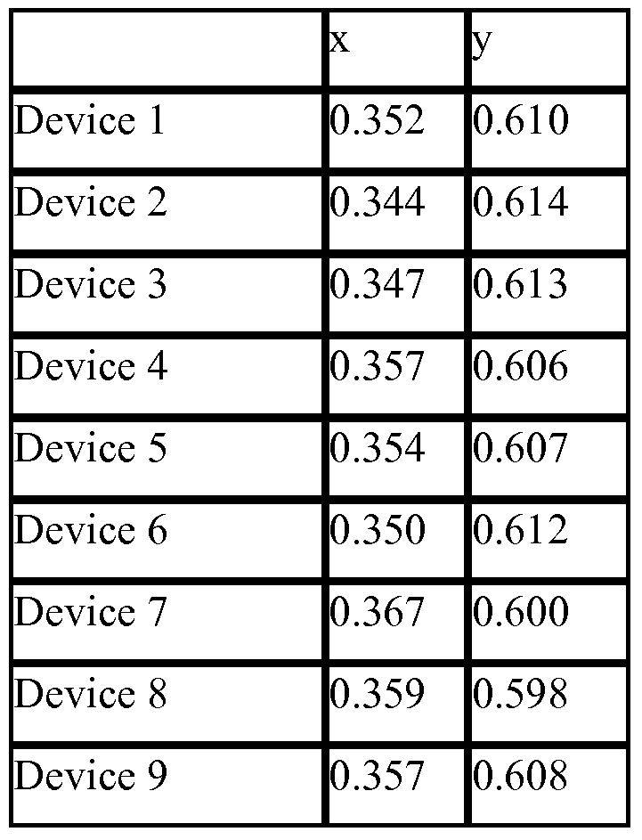
- compounds 1, 2, 3, 4, and 11, based on substructures G and F were found to have significantly less red shifting of the emission of the green dopant compared to comparative example 1 and 2 as demonstrated by the CIE coordinates given in Table 1 and the EL spectra shown in Figures 3 and 6.
- compounds 7 and 8, based on substructures H and I were also found to have less red shifting compared to comparative example 1 as shown by the CIE coordinates in Table 1 , but less so than the previously described examples.
- the color shifting effect of the host is important tool for designing device structures that provide more saturated green emission.
- the device data demonstrates that single triphenylene containing hosts materials offer advantages with respect to the CIE coordinates compared to two triphenylene containing comparative examples.
- compounds 1, 2, 4, 5, and 8 are very soluble in organic solvent and were used as phosphorescent hosts in solution processed devices. It is believed in these examples that meta substituted aryl rings can help reduce symmetry and improve solubility.
- Data for solution processed devices using single triphenylene containing materials as hosts is shown in Table 2. In comparison, the two triphenylene containing comparative examples 1 and 2 are not soluble enough for solution processing. Therefore, single triphenylene containing materials can have considerable advantages in terms of solubility and processibility.
- substructures F-M are preferred.
- triphenylene is substituted with a phenyl ring that contains additional meta-aryl substitution which is an important difference when compared to an example that can be found in WO 2007/108362. It is important that the phenyl ring substituted on the triphenylene be further substituted in the meta position in order to limit direct phenyl-phenyl conjugation. It is believed that four para substituted phenyl rings may result in a low enough triplet energy to quench green phosphorescent emission. Therefore substructures F, G, H and I are the most preferred substructures where there are no more than three para substituted phenyl rings.
- the material will sublime at a very low temperature making the deposition process difficult to control.
- a very low molecular weight may result in a material that has a low glass transition temperature (T g ). If a material has a low T g and if it is very planar with high symmetry, the material may not form a stable amorphous film and may tend to crystallize. Low T g may result in poor thermal stability and can also result in poor device performance. Comparative examples 3 and 4 do not have additional phenyl substitutions and it is believed that their low molecular weight results in poor thermal stability and therefore poor device performance. This is shown by the device lifetime in Figure 8.
- Devices 2-6 use host materials with higher molecular weight and therefore result in much better device stability, as shown in Figure 5 where T50 » 100 hrs.
- the single triphenylene chromophore aspect of the invention describes single triphenylene containing materials for use as hosts and enhancement layers in phosphorescent organic light emitting diodes. These materials may offer advantages over hosts and enhancement layers containing two triphenylene chromophores. Single triphenylene containing derivatives may be easier to synthesize as only a single coupling reaction of triphenylene is required. In addition, these materials may be more soluble allowing for purification techniques, such as, column chromatography and recrystallization. The improved solubility can also allow for these materials to be used as materials in devices that are fabricated by a solvent process, such as spin casting or ink jet printing. Finally, it has been experimentally realized that single triphenylene hosts, did not red shift the emission of the phosphorescent dopant as compared to devices fabricated with the comparative examples 1 and 2. This effect may allow for devices to be fabricated that have improved color saturation.
- Bphen 4,7-diphenyl- 1 , 10-phenanthroline
- n-BPhen n-doped BPhen (doped with lithium)
- F 4 -TCNQ tetrafluoro-tetracyano-quinodimethane
- p-MTDATA p-doped m-MTDATA (doped with F 4 -TCNQ)
- TAZ 3-phenyl-4-(r-naphthyl)-5-phenyl-l,2,4-triazole
- CuPc copper phthalocyanine
- ITO indium tin oxide
- NPD N,N'-diphenyl-N-N'-di(l-naphthyl)-benzidine
- BAIq aluminum(III)bis(2-methyl-8-hydroxyquinolinato)4-phenylphenolate mCP: 1 ,3-N,N-dicarbazole-benzene
- PEDOT:PSS an aqueous dispersion of poly(3,4-ethylenedioxythiophene) with polystyrenesulfonate (PSS)
- tr is [5 -phenyl(2 -pheny lpyridine) ] iridium(III) Ir(pq) 2 (acac) bis[2-phenylquinoline)]iridium(III) acetylacetonate
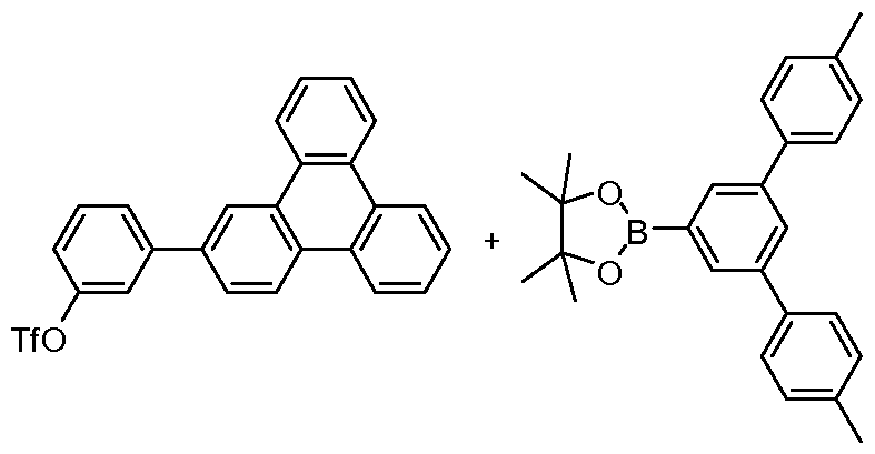
- Triphenylene (19.0 g, 83 mmol) was added to and 600 mL of nitrobenzene. After all the triphenylene had dissolved, iron powder (0.07 g, 1.25 mmol) was added. The reaction flask was put in an ice bath. Bromine (20.0 g 125 mmol) in 50 mL of nitrobenzene was slowly added via addition funnel. After that, the reaction was stirred in an ice bath for 5 hours. HPLC was performed to monitor the reaction (TLC did not show separation of triphenylene and bromotriphenylenes).
- the crude product was purified by column using a mixture of hexanes and dichloromethane (from 6:1 to 3:1) as eluent. 10 g of the pure product, 4,4,5,5- tetramethyl-2-(triphenylen-2-yl)-l ,3,2-dioxaborolane, was isolated.
- reaction mixture was cooled and diluted with dichloromethane and washed with water twice.
- the organic layer was dried over magnesium sulfate, filtered and evaporated.
- the mixture was purified by column chromatography eluting with up to 5% ethyl acetate/hexanes.
- the solid was further purified by the recrystallization from hot hexanes to get 3.9 gram white solid (76%).
- reaction mixture was cooled and diluted with dichloromethane and washed with water twice.
- the organic layer was dried over magnesium sulfate, filtered and evaporated.
- the mixture was purified by column chromatography eluting with up to 5% ethyl acetate/hexanes.
- the solid was further purified by recrystallization from hot hexanes to get 2.5 gram white solid (63%).
- a mixture was prepared consisting of 1 ,2-dibromobenzene (50 g, 212 mmol), 4- methoxyphenylboronic acid (78 g, 513 mmol), triphenylphosphine (11.12 g, 42.2 mmol), potassium carbonate (73.25 g, 530 mmol), dimethoxyethane (290 mL), and water (290 mL). Nitrogen was bubbled directly into the mixture for 20 minutes. Palladium acetate was added (4.76 g, 21.2 mmol) and the mixture was heated to reflux overnight under nitrogen. The reaction mixture was cooled and water and dichloromethane was added.
- the layers were separated and the aqueous layer was extracted with dichloromethane.
- the combined organic layers were filtered through Celite and washed with brine, dried over magnesium sulfate, filtered, evaporated to a yield a black oil.
- the crude material was purified by column chromatography eluting with 0 to 100% dichloromethane/hexanes.
- the cleanest fractions were purified by distillation using a Kugelrohr at 200 to 220 0 C. The product remained in the boiling flask and the impurity distilled into the bulb along with some product. Obtained 49g (80%) of clean product.
- Triphenylene-2,11-diol (7.45g, 28.62 mmol) was added to 100 mL dichloromethane and 13 mL pyridine and the solution was cooled in an ice salt bath.
- Trifluoromethanesulfonic anhydride (19 mL, 114.49 mmol) in 70 mL of dichloromethane was added dropwise to the solution under nitrogen. The reaction was allowed to proceed for 2 hours and quenched by adding by adding methanol and water followed by dilution with dichloromethane. A tan solid was filtered off and washed with dichloromethane and water. The layers in the filtrate were separated and the aqueous layer was extracted with dichloromethane.
- the organic extracts were dried over magnesium sulfate, filtered, and evaporated to yield a brown solid.
- the brown solid was purified by column chromatography eluting with 0 to 100% dichloromethane/hexanes. Obtained 1.8g of desired product.
- the tan solid that was filtered in the work-up was purified by sublimation at 170 0 C followed by recrystallization twice from 300 mL boiling toluene. Obtained 9.6g of desired material, 11.4g total (76%).
- a mixture was prepared of l-Bromo-3,4-dichlorobenzene (20.0 g, 88.5 mmol), phenylboronic acid (13.5 g, 110.6 mmol), triphenylphosphine (2.32 g, 8.85 mmol), potassium carbonate (30.58 g, 221.25 mmol), 150 mL xylenes, and 150 mL water.
- the mixture was stirred and nitrogen bubbled into it for 20 minutes.
- Palladium acetate was added (0.99 g, 4.425 mmol) and the mixture was heated at 120 0 C under nitrogen overnight. Cooled to room temperature and diluted with water and dichloromethane.
- the mixture was filtered through Celite and the Celite was washed with water and dichloromethane. The layers were separated and the aqueous layer extracted with dichloromethane. The organic layers were dried over magnesium sulfate, filtered, and evaporated to yield a brown oil.
- the crude material was purified by column chromatography eluting with hexanes. The cleanest fractions containing product were collected. Obtained 6 g (30%) of clean product.
- the reaction was quenched with methanol and aqueous sodium sulfite solution and diluted with dichloromethane. The layers were separated and the aqueous layer was extracted with dichloromethane. The organic layers were dried over magnesium sulfate, filtered, and evaporated to a residue which was taken up in dichloromethane. An insoluble gray solid was filtered off. The filtrate was evaporated and purified by column chromatography eluting with dichloromethane/hexanes. The product was recrystallized from xylenes, and then sublimed at 250 0 C.
- the material was sublimed at 190 0 C for 4 days to remove impurity, then purified by column chromatography eluting with 3:1 hexanes: dichloromethane to remove color. Lastly material was sublimed at 230 0 C to obtain 0.98 g (20%) of a white solid.
- the reaction was quenched with methanol and aqueous sodium sulfite solution and diluted with dichloromethane. An emulsion resulted; the mixture was then filtered through Celite. The layers were separated and the aqueous layer was extracted with dichloro methane. The organic layers were washed with brine, dried over magnesium sulfate, filtered, evaporated to a residue. The residue was purified by column chromatography twice eluting with dichloromethane/hexanes followed by sublimation at 210 0 C. Obtained 0.51g (12%) of a white solid.
- VTE device data
- ITO/HIL(100 A)/HTL(300 A )/EML(300 A)/ETL2(50 A)/ETL1(45O A)/LiF/Al ITO/HIL(100 A)/HTL(300 A )/EML(300 A)/ETL2(50 A)/ETL1(45O A)/LiF/Al.
- HIL is the hole injection layer
- HTL is the hole transport layer
- EML is the doped emissive layer
- ETL2 is the enhancement layer
- ETL is the electron transport layer.
- All devices were fabricated with an HIL comprised of dopant 1, an HTL of NPD and an ETL OfAIq 3 .
- the EML were comprised of various single triphenylene hosts doped at 10 wt% with the green emissive dopant 1.
- the BL used were either HPT or the triphenylene containing host.
- a 10 A thick layer of LiF followed by a 1000 A thick layer of Al was used as the cathode. All devices were lifetested at a constant current density of 40 mA/cm 2 .
- the characteristics of the VTE devices are shown in Table 1 and Figures 3-8.
- Device 1 ITO/dopant 1/NPD/Compound l :dopant 1 (10%)/Compound 1/ Alq 3 /LiF/Al
- Device 2 ITO/dopant 1/NPD/Compound 2:dopant 1 (10%)/Compound 2/ Alq 3 LiF/Al
- Device 3 ITO/dopant 1/NPD/Compound 4:dopant 1 (10%)/Compound 4/ Alq 3 /LiF/Al
- Device 4 ITO/dopant 1/NPD/Compound 7:dopant 1 (10%)/HPT/ Alq 3 /LiF/Al
- Device 5 ITO/dopant 1/NPD/Compound 8:dopant 1 (10%)/HPT/ Alq 3 /LiF/Al
- Device 6 ITO/dopant 1/NPD/Compound 11 :dopant 1 (10%)/HPT/ Alq 3 /LiF/Al
- Device 7 ITO/dopant 1/NPD/Comparative example l:dopant 1 (10%)/HPT/ Alq 3 /LiF/Al
- Device 8 ITO/dopant 1/NPD/Comparative example 3:dopant 1 (10%)/comparative example 3/ Alq 3 /LiF/Al
- Device 9 ITO/dopant 1/NPD/Comparative example 4:dopant 1 (10%)/comparative example 4/ Alq 3 /LiF/Al
- Dopant 1 and HPT have the following structures:
- Solution processed device data [0134] Devices 10-15 were fabricated using a solution process as follows: The hole injection layer was spin-coated from a 0.25 wt% solution of the HIL and the dopant trityl- tetrakis(pentafluorophenyl)borate (CDl) in cyclohexanone at 4000 rpm for 30 seconds. The film was baked at 250 0 C for 30 min.
- a 1.0 wt% solution of N4,N4'- di(naphthalen-l-yl)-N4,N4'-bis(4-vinylphenyl)biphenyl-4,4'-diamine in toluene was spin-coated onto the hole injection layer at 4000 rpm for 30 seconds.
- the film was then baked at 200 0 C for 30 minutes on a hot plate in a glovebox. The film became insoluble after baking.
- the emissive layer was deposited by spin-coating a solution of 0.75 wt% host and dopant 2 (host to dopant ratio: 88:12) onto the hole transport layer at 1000 rpm for 30 seconds.
- the emissive layer was then baked at 100 0 C for one hour.
- a 5 nm thick layer of 2,3,6,7,10,11 -hexaphenyltriphenylene (HPT) and a 50 nm thick layer OfAIq 3 were subsequently deposited by vacuum thermal evaporation followed by a LiF/ Al cathode.
- Dopant 2 A mixture of compounds Gl, G2, G3, and G4 in a ratio of 2:37:53:7.
- Phosphorescent devices with very high device efficiency are highly desirable in applications such as display, lighting, etc. For full color and lighting application, high operational stability in red, green and blue colors is essential. Due to the high triplet energy nature of blue phosphorescent dopant emitters, high triplet energy host materials are required so that high device efficiency can be obtained.
- polyaromatic compounds with extended ⁇ -conjugation usually show respectable lifetimes. However, polyaromatic compounds with extended ⁇ -conjugation usually have low triplet energy also. For example, anthracene has a triplet energy of 1.8 eV which is lower than those of red phosphorescent dopants such as Ir(I- piq)2(acac).
- a device with an anthracene compound as the host with Ir( 1 -piq)2(acac) as the dopant emitter is very inefficient, because of quenching. Reducing one fused phenyl ring from anthracene gives naphthalene which is the smallest fused polyaromatic compound. Yet it still has a triplet energy of 2.6 eV which is lower than those of deep blue phosphorescent dopants such as Ir(4,6-F2-5CNppy)3.
- triphenylene despite its four fused ring configuration, has a triplet energy of 2.9 eV which is believed to be suitable for deep blue phosphorescent dopants such as Ir(4,6-F2-5CNppy)3.
- Triphenylene can be derivatized in various ways such as adding alkyl or aryl groups, linking multiple or fusing triphenylenes through different positions to modulate the electronic properties (e.g. conjugation, triplet energy, H0M0/LUM0 levels, etc), structure properties (e.g., planar, non-planar, chirality), and physical properties (e.g., sublimation temperature, solubility).
- the unique property that triphenylene compounds provides relatively large degree of ⁇ -conjugation but relatively high triplet energy renders them very suitable for stable and high-efficiency PHOLEDs.
Abstract
Description


Claims


Priority Applications (19)
| Application Number | Priority Date | Filing Date | Title |
|---|---|---|---|
| US12/865,628 US8652652B2 (en) | 2007-08-08 | 2008-08-07 | Single triphenylene chromophores in phosphorescent light emitting diodes |
| JP2010520304A JP5722036B2 (en) | 2007-08-08 | 2008-08-07 | Single triphenylene chromophore in phosphorescent light-emitting diodes |
| KR1020107005026A KR101665726B1 (en) | 2007-08-08 | 2008-08-07 | Single triphenylene chromophores in phosphorescent light emitting diodes |
| EP18186360.6A EP3424918A1 (en) | 2007-08-08 | 2008-08-07 | Single triphenylene chromophores in phosphorescent light emitting diodes |
| EP08826903.0A EP2200956B1 (en) | 2007-08-08 | 2008-08-07 | Single triphenylene chromophores in phosphorescent light emitting diodes |
| EP16168868.4A EP3112336B1 (en) | 2007-08-08 | 2008-08-07 | Single triphenylene chromophores in phosphorescent light emitting diodes |
| KR1020207034238A KR102342708B1 (en) | 2007-08-08 | 2008-08-07 | Single triphenylene chromophores in phosphorescent light emitting diodes |
| CN200880105628.0A CN101808964B (en) | 2007-08-08 | 2008-08-07 | Single triphenylene [9,10] chromophores in phosphorescent light emitting diodes |
| KR1020217041333A KR102513201B1 (en) | 2007-08-08 | 2008-08-07 | Single triphenylene chromophores in phosphorescent light emitting diodes |
| KR1020207002793A KR102189768B1 (en) | 2007-08-08 | 2008-08-07 | Single triphenylene chromophores in phosphorescent light emitting diodes |
| KR1020157008556A KR20150041196A (en) | 2007-08-08 | 2008-08-07 | Single triphenylene chromophores in phosphorescent light emitting diodes |
| KR1020177021334A KR102073400B1 (en) | 2007-08-08 | 2008-08-07 | Single triphenylene chromophores in phosphorescent light emitting diodes |
| KR1020167023633A KR20160104752A (en) | 2007-08-08 | 2008-08-07 | Single triphenylene chromophores in phosphorescent light emitting diodes |
| US14/135,191 US9608206B2 (en) | 2007-08-08 | 2013-12-19 | Organic electroluminescent materials and devices |
| US14/491,280 US9590180B2 (en) | 2007-06-23 | 2014-09-19 | Organic electroluminescent materials and devices |
| US15/449,497 US10312450B2 (en) | 2007-08-08 | 2017-03-03 | Organic electroluminescent materials and devices |
| US16/385,083 US10957858B2 (en) | 2007-08-08 | 2019-04-16 | Organic electroluminescent materials and devices |
| US17/176,692 US11690286B2 (en) | 2007-08-08 | 2021-02-16 | Organic electroluminescent materials and devices |
| US18/328,519 US20230320196A1 (en) | 2007-08-08 | 2023-06-02 | Organic electroluminescent materials and devices |
Applications Claiming Priority (4)
| Application Number | Priority Date | Filing Date | Title |
|---|---|---|---|
| US96394407P | 2007-08-08 | 2007-08-08 | |
| US60/963,944 | 2007-08-08 | ||
| US1750607P | 2007-12-28 | 2007-12-28 | |
| US61/017,506 | 2007-12-28 |
Related Child Applications (2)
| Application Number | Title | Priority Date | Filing Date |
|---|---|---|---|
| US12/865,628 A-371-Of-International US8652652B2 (en) | 2007-08-08 | 2008-08-07 | Single triphenylene chromophores in phosphorescent light emitting diodes |
| US14/135,191 Continuation US9608206B2 (en) | 2007-06-23 | 2013-12-19 | Organic electroluminescent materials and devices |
Publications (1)
| Publication Number | Publication Date |
|---|---|
| WO2009021107A1 true WO2009021107A1 (en) | 2009-02-12 |
Family
ID=40029129
Family Applications (1)
| Application Number | Title | Priority Date | Filing Date |
|---|---|---|---|
| PCT/US2008/072452 WO2009021107A1 (en) | 2007-06-23 | 2008-08-07 | Single triphenylene chromophores in phosphorescent light emitting diodes |
Country Status (7)
| Country | Link |
|---|---|
| US (7) | US8652652B2 (en) |
| EP (4) | EP3112336B1 (en) |
| JP (6) | JP5722036B2 (en) |
| KR (7) | KR20150041196A (en) |
| CN (2) | CN103601609B (en) |
| TW (4) | TWI501943B (en) |
| WO (1) | WO2009021107A1 (en) |
Cited By (38)
| Publication number | Priority date | Publication date | Assignee | Title |
|---|---|---|---|---|
| WO2011032686A1 (en) | 2009-09-16 | 2011-03-24 | Merck Patent Gmbh | Formulas for producing electronic devices |
| WO2011086867A1 (en) * | 2010-01-15 | 2011-07-21 | 富士フイルム株式会社 | Organic electroluminescent element |
| JP4751955B1 (en) * | 2010-07-09 | 2011-08-17 | 富士フイルム株式会社 | Organic electroluminescence device |
| WO2011137157A1 (en) * | 2010-04-28 | 2011-11-03 | Universal Display Corporation | Triphenylene-benzofuran/benzothiophene/benzoselenophene compounds with substituents joining to form fused rings |
| WO2011137922A1 (en) | 2010-05-03 | 2011-11-10 | Merck Patent Gmbh | Formulations and electronic devices |
| JP2012001449A (en) * | 2010-06-14 | 2012-01-05 | Mitsubishi Chemicals Corp | Compound, charge transport material, composition for organic electroluminescent element, organic electroluminescent element, organic el display and organic el illumination |
| CN102687299A (en) * | 2009-12-23 | 2012-09-19 | 默克专利有限公司 | Composition for the preparation of organic electronic (oe) devices |
| CN102986050A (en) * | 2010-06-10 | 2013-03-20 | 诺瓦莱德公开股份有限公司 | Electronic device comprising an organic semiconducting material |
| WO2013072740A2 (en) | 2011-11-15 | 2013-05-23 | ユーディーシー アイルランド リミテッド | Charge-transporting material, organic electroluminescent element, and light-emitting device, display device and illumination device characterised by using said element |
| JP2013530515A (en) * | 2010-04-28 | 2013-07-25 | ユニバーサル ディスプレイ コーポレイション | Premixed material deposition |
| DE102013200942A1 (en) | 2012-01-23 | 2013-07-25 | Udc Ireland Ltd. | Organic electroluminescent element useful e.g. for display device, comprises substrate, pair of electrodes, and organic layer comprising light-emitting layer, which comprises substituted 4,5-dihydro-pyrrolo(3,2,1-jk)carbazole derivatives |
| US20130200359A1 (en) * | 2010-10-15 | 2013-08-08 | Merck Patent Gmbh | Triphenylene-based materials for organic electroluminescent devices |
| KR20140020935A (en) * | 2011-03-31 | 2014-02-19 | 유디씨 아일랜드 리미티드 | Charge transport material, organic electroluminescent element, and illumination device, display device, or light-emitting device characterized by using said element |
| US20140225085A1 (en) * | 2011-04-12 | 2014-08-14 | Udc Ireland Limited | Organoelectroluminescent Element, and Light Emission Device, Display Device, and Illumination Device in which Said Organoelectroluminescent Element is Used |
| US8841653B2 (en) | 2009-05-29 | 2014-09-23 | Semiconductor Energy Laboratory Co., Ltd. | Light-emitting element, light-emitting device, lighting device, and electronic appliance |
| US9065058B2 (en) | 2010-09-10 | 2015-06-23 | Semiconductor Energy Laboratory Co., Ltd. | Light-emitting element and electronic device |
| WO2015139808A1 (en) | 2014-03-18 | 2015-09-24 | Merck Patent Gmbh | Organic electroluminescent device |
| WO2016034262A1 (en) | 2014-09-05 | 2016-03-10 | Merck Patent Gmbh | Formulations and electronic devices |
| EP2998300A1 (en) * | 2013-05-16 | 2016-03-23 | Cheil Industries Inc. | Organic compound, organic optoelectronic element, and display device |
| KR20160036634A (en) | 2010-09-08 | 2016-04-04 | 유디씨 아일랜드 리미티드 | Organic electroluminescent element and charge transport material |
| US9309223B2 (en) | 2011-07-08 | 2016-04-12 | Semiconductor Energy Laboratory Co., Ltd. | Heterocyclic compound, light-emitting element, light-emitting device, electronic device, and lighting device |
| EP2511254B1 (en) | 2007-08-08 | 2016-05-11 | Universal Display Corporation | Single triphenylene chromophores in phosphorescent light emitting diodes |
| US9406893B2 (en) | 2010-09-09 | 2016-08-02 | Semiconductor Energy Laboratory Co., Ltd. | Heterocyclic compound, light-emitting element, light-emitting device, electronic device, and lighting device |
| US9406889B2 (en) | 2010-10-29 | 2016-08-02 | Semiconductor Energy Laboratory Co., Ltd. | Phenanthrene compound, light-emitting element, light-emitting device, electronic device, and lighting device |
| US9496505B2 (en) | 2010-10-04 | 2016-11-15 | Semiconductor Energy Laboratory Co., Ltd. | Composite material, light-emitting element, light-emitting device, electronic device, and lighting device |
| WO2016188609A1 (en) | 2015-05-22 | 2016-12-01 | Merck Patent Gmbh | Formulation containing an organic semiconductor and a metal complex |
| US9520567B2 (en) | 2013-05-16 | 2016-12-13 | Cheil Industries, Inc. | Luminescent material for organic optoelectric device and organic optoelectric device and display device |
| US9741955B2 (en) | 2009-05-29 | 2017-08-22 | Semiconductor Energy Laboratory Co., Ltd. | Light-emitting element, light-emitting device, and method for manufacturing the same |
| US9799834B2 (en) | 2011-08-18 | 2017-10-24 | Semiconductor Energy Laboratory Co., Ltd. | Carbazole compound light-emitting element, light-emitting device, electronic device, and lighting device |
| US9831435B2 (en) | 2011-03-23 | 2017-11-28 | Semiconductor Energy Laboratory Co., Ltd. | Composite material, light-emitting element, light-emitting device, electronic device, and lighting device |
| US9882135B2 (en) | 2010-05-03 | 2018-01-30 | Merck Patent Gmbh | Formulations and electronic devices |
| US9905782B2 (en) | 2013-03-26 | 2018-02-27 | Semiconductor Energy Laboratory Co., Ltd. | Light-emitting element, compound, organic compound, display module, lighting module, light-emitting device, display device, lighting device, and electronic device |
| US9960368B2 (en) | 2011-02-01 | 2018-05-01 | Semiconductor Energy Laboratory Co., Ltd. | Heterocyclic compound |
| KR20180057726A (en) | 2010-07-29 | 2018-05-30 | 유디씨 아일랜드 리미티드 | Organic electroluminescent element and charge transport material |
| US10071993B2 (en) | 2010-09-21 | 2018-09-11 | Semiconductor Energy Laboratory Co., Ltd. | Carbazole derivative, light-emitting element material and organic semiconductor material |
| US10424745B2 (en) | 2009-11-02 | 2019-09-24 | Semiconductor Energy Laboratory Co., Ltd. | Organometallic complex, light-emitting element, display device, electronic device, and lighting device |
| US10804469B2 (en) | 2011-03-31 | 2020-10-13 | Udc Ireland Limited | Charge transport material, organic electroluminescent element, and illumination device, display device, or light-emitting device characterized by using said element |
| US11107995B2 (en) | 2016-06-24 | 2021-08-31 | Semiconductor Energy Laboratory Co., Ltd. | Organic compound, light-emitting element, light-emitting device, electronic device, and lighting device |
Families Citing this family (36)
| Publication number | Priority date | Publication date | Assignee | Title |
|---|---|---|---|---|
| JPH1144632A (en) * | 1997-07-28 | 1999-02-16 | Toa Medical Electronics Co Ltd | Method for determining abnormality in data of particle-measuring device |
| US8007927B2 (en) | 2007-12-28 | 2011-08-30 | Universal Display Corporation | Dibenzothiophene-containing materials in phosphorescent light emitting diodes |
| JP2011225501A (en) * | 2010-04-22 | 2011-11-10 | Canon Inc | Novel m-terphenyl compound and organic light-emitting element including the same |
| JP5815280B2 (en) | 2010-05-21 | 2015-11-17 | 株式会社半導体エネルギー研究所 | Triazole derivative |
| KR101338345B1 (en) * | 2010-10-14 | 2013-12-06 | 엘지디스플레이 주식회사 | organic electroluminescent display device |
| US9252377B2 (en) * | 2011-07-14 | 2016-02-02 | Universal Display Corporation | Inorganic hosts in OLEDs |
| JP2013093541A (en) | 2011-10-06 | 2013-05-16 | Udc Ireland Ltd | Organic electroluminescent element and compound and material for organic electroluminescent element usable therefor, and luminescent device, display device and lighting device using the element |
| JP2013084732A (en) | 2011-10-07 | 2013-05-09 | Udc Ireland Ltd | Organic field light-emitting element and light-emitting material for the same, and light-emitting device, display device and illuminating device |
| JP2013118349A (en) | 2011-11-02 | 2013-06-13 | Udc Ireland Ltd | Organic electroluminescent element, material for organic electroluminescent element, and light emitting device, display device and illumination device which employ said organic electroluminescent element |
| JP6118034B2 (en) | 2012-02-06 | 2017-04-19 | ユー・ディー・シー アイルランド リミテッド | ORGANIC ELECTROLUMINESCENT ELEMENT, COMPOUND USABLE FOR THE SAME, ORGANIC ELECTROLUMINESCENT ELEMENT MATERIAL, AND LIGHT EMITTING DEVICE, DISPLAY DEVICE AND LIGHTING DEVICE USING THE ELEMENT |
| JP6126577B2 (en) * | 2012-02-28 | 2017-05-10 | 保土谷化学工業株式会社 | Compound having pyridyl group having substituent and triphenylene ring structure, and organic electroluminescence device |
| JP5911418B2 (en) | 2012-12-27 | 2016-04-27 | キヤノン株式会社 | Organic light emitting device |
| KR101506869B1 (en) * | 2013-03-26 | 2015-04-08 | 한국교통대학교산학협력단 | pyrazole derivative and organoelectroluminescent device employing the same |
| KR101618683B1 (en) | 2013-05-16 | 2016-05-09 | 제일모직 주식회사 | Organic compound and organic optoelectric device and display device |
| KR101433822B1 (en) | 2013-06-17 | 2014-08-27 | 삼성디스플레이 주식회사 | Organic light emitting diode device |
| KR102188028B1 (en) | 2013-06-18 | 2020-12-08 | 삼성디스플레이 주식회사 | Organic light emitting device |
| KR101627761B1 (en) | 2013-07-10 | 2016-06-07 | 제일모직 주식회사 | Organic compound and organic optoelectric device and display device |
| CN105874626B (en) * | 2013-12-26 | 2017-09-22 | 新日铁住金化学株式会社 | Organic electric-field light-emitting element material and use its organic electric-field light-emitting element |
| KR102182943B1 (en) * | 2013-12-26 | 2020-11-25 | 닛테츠 케미컬 앤드 머티리얼 가부시키가이샤 | Material for organic electroluminescent elements, and organic electroluminescent element using same |
| CN104795503B (en) | 2014-01-16 | 2018-07-20 | 三星显示有限公司 | Organic light emitting apparatus |
| WO2015134017A1 (en) | 2014-03-05 | 2015-09-11 | Universal Display Corporation | Phosphorescent oled devices |
| US10115930B2 (en) * | 2014-07-08 | 2018-10-30 | Universal Display Corporation | Combined internal and external extraction layers for enhanced light outcoupling for organic light emitting device |
| US10297762B2 (en) | 2014-07-09 | 2019-05-21 | Universal Display Corporation | Organic electroluminescent materials and devices |
| US9944846B2 (en) * | 2014-08-28 | 2018-04-17 | E I Du Pont De Nemours And Company | Compositions for electronic applications |
| US10749113B2 (en) | 2014-09-29 | 2020-08-18 | Universal Display Corporation | Organic electroluminescent materials and devices |
| US10361375B2 (en) | 2014-10-06 | 2019-07-23 | Universal Display Corporation | Organic electroluminescent materials and devices |
| US9929361B2 (en) * | 2015-02-16 | 2018-03-27 | Universal Display Corporation | Organic electroluminescent materials and devices |
| WO2016193845A1 (en) | 2015-05-29 | 2016-12-08 | Semiconductor Energy Laboratory Co., Ltd. | Light-emitting element, light-emitting device, display device, electronic device, and lighting device |
| US11522140B2 (en) | 2015-08-17 | 2022-12-06 | Universal Display Corporation | Organic electroluminescent materials and devices |
| CN108431010B (en) | 2015-12-25 | 2021-10-15 | 株式会社半导体能源研究所 | Compound, light-emitting element, display device, electronic device, and lighting device |
| CN109641840B (en) | 2016-07-27 | 2022-11-18 | 株式会社Lg化学 | Polycyclic compound and organic light emitting device comprising the same |
| CN106981574B (en) * | 2017-04-18 | 2019-07-05 | 浙江蓝绿新材料科技有限公司 | A kind of long-life perovskite photovoltaic cell and preparation method thereof |
| US11871653B2 (en) * | 2019-02-22 | 2024-01-09 | Universal Display Corporation | Organic electroluminescent materials and devices |
| US11827651B2 (en) * | 2019-05-13 | 2023-11-28 | Universal Display Corporation | Organic electroluminescent materials and devices |
| KR20220007767A (en) * | 2020-07-09 | 2022-01-19 | 덕산네오룩스 주식회사 | Compound for organic electronic element, organic electronic element using the same, and an electronic device thereof |
| KR20220052748A (en) | 2020-10-21 | 2022-04-28 | 엘지디스플레이 주식회사 | Vibration apparatus and apparatus comprising the same |
Citations (30)
| Publication number | Priority date | Publication date | Assignee | Title |
|---|---|---|---|---|
| US4769292A (en) | 1987-03-02 | 1988-09-06 | Eastman Kodak Company | Electroluminescent device with modified thin film luminescent zone |
| US5247190A (en) | 1989-04-20 | 1993-09-21 | Cambridge Research And Innovation Limited | Electroluminescent devices |
| US5703436A (en) | 1994-12-13 | 1997-12-30 | The Trustees Of Princeton University | Transparent contacts for organic devices |
| US5707745A (en) | 1994-12-13 | 1998-01-13 | The Trustees Of Princeton University | Multicolor organic light emitting devices |
| US5834893A (en) | 1996-12-23 | 1998-11-10 | The Trustees Of Princeton University | High efficiency organic light emitting devices with light directing structures |
| US5844363A (en) | 1997-01-23 | 1998-12-01 | The Trustees Of Princeton Univ. | Vacuum deposited, non-polymeric flexible organic light emitting devices |
| US6013982A (en) | 1996-12-23 | 2000-01-11 | The Trustees Of Princeton University | Multicolor display devices |
| US6087196A (en) | 1998-01-30 | 2000-07-11 | The Trustees Of Princeton University | Fabrication of organic semiconductor devices using ink jet printing |
| US6091195A (en) | 1997-02-03 | 2000-07-18 | The Trustees Of Princeton University | Displays having mesa pixel configuration |
| US6097147A (en) | 1998-09-14 | 2000-08-01 | The Trustees Of Princeton University | Structure for high efficiency electroluminescent device |
| US6294398B1 (en) | 1999-11-23 | 2001-09-25 | The Trustees Of Princeton University | Method for patterning devices |
| US6303238B1 (en) | 1997-12-01 | 2001-10-16 | The Trustees Of Princeton University | OLEDs doped with phosphorescent compounds |
| US6310360B1 (en) | 1999-07-21 | 2001-10-30 | The Trustees Of Princeton University | Intersystem crossing agents for efficient utilization of excitons in organic light emitting devices |
| US6337102B1 (en) | 1997-11-17 | 2002-01-08 | The Trustees Of Princeton University | Low pressure vapor phase deposition of organic thin films |
| US20020034656A1 (en) | 1998-09-14 | 2002-03-21 | Thompson Mark E. | Organometallic complexes as phosphorescent emitters in organic LEDs |
| WO2002074015A2 (en) | 2001-03-14 | 2002-09-19 | The Trustees Of Princeton University | Materials and devices for blue phosphorescence based organic light emitting diodes |
| US20020182441A1 (en) | 2000-08-11 | 2002-12-05 | Trustee Of Princeton University | Organometallic compounds and emission-shifting organic electrophosphorescence |
| US6548956B2 (en) | 1994-12-13 | 2003-04-15 | The Trustees Of Princeton University | Transparent contacts for organic devices |
| US20030072964A1 (en) | 2001-10-17 | 2003-04-17 | Kwong Raymond C. | Phosphorescent compounds and devices comprising the same |
| US6576134B1 (en) | 1998-10-20 | 2003-06-10 | Erik Agner | Method for displacement chromatography |
| US6602540B2 (en) | 1996-08-12 | 2003-08-05 | The Trustees Of Princeton University | Fabrication of non-polymeric flexible organic light emitting devices |
| JP2003282270A (en) * | 2002-03-25 | 2003-10-03 | Konica Corp | Organic electroluminescent device and display using the same |
| US20030230980A1 (en) | 2002-06-18 | 2003-12-18 | Forrest Stephen R | Very low voltage, high efficiency phosphorescent oled in a p-i-n structure |
| US20050025993A1 (en) | 2003-07-25 | 2005-02-03 | Thompson Mark E. | Materials and structures for enhancing the performance of organic light emitting devices |
| EP1621597A1 (en) * | 2003-05-01 | 2006-02-01 | Fujitsu Limited | 1,3,6,8-tetrasubstituted pyrene compounds, organic el device and organic el display |
| WO2006047119A1 (en) * | 2004-10-22 | 2006-05-04 | Universal Display Corporation | Arylcarbaz as hosts in phosphorescent organic light emitting devices |
| WO2006130598A2 (en) | 2005-05-31 | 2006-12-07 | Universal Display Corporation | Triphenylene hosts in phosphorescent light emitting diodes |
| WO2007108362A1 (en) | 2006-03-17 | 2007-09-27 | Konica Minolta Holdings, Inc. | Organic electroluminescent device, display and illuminating device |
| JP2008150365A (en) * | 2006-11-20 | 2008-07-03 | Chisso Corp | Electron transport material and organic electroluminescent device using the same |
| WO2008122943A1 (en) * | 2007-04-04 | 2008-10-16 | Philips Intellectual Property & Standards Gmbh | Oled with metal complexes having a high quantum efficiency |
Family Cites Families (129)
| Publication number | Priority date | Publication date | Assignee | Title |
|---|---|---|---|---|
| US1750607A (en) | 1926-04-09 | 1930-03-11 | Gen Motors Res Corp | Spring shackle |
| US5061569A (en) | 1990-07-26 | 1991-10-29 | Eastman Kodak Company | Electroluminescent device with organic electroluminescent medium |
| EP0650955B1 (en) | 1993-11-01 | 1998-08-19 | Hodogaya Chemical Co., Ltd. | Amine compound and electro-luminescence device comprising same |
| US6939625B2 (en) | 1996-06-25 | 2005-09-06 | Nôrthwestern University | Organic light-emitting diodes and methods for assembly and enhanced charge injection |
| US6294396B1 (en) * | 1998-08-11 | 2001-09-25 | Advanced Micro Devices, Inc. | Monitoring barrier metal deposition for metal interconnect |
| US6528187B1 (en) | 1998-09-08 | 2003-03-04 | Fuji Photo Film Co., Ltd. | Material for luminescence element and luminescence element using the same |
| US6458475B1 (en) | 1999-11-24 | 2002-10-01 | The Trustee Of Princeton University | Organic light emitting diode having a blue phosphorescent molecule as an emitter |
| US6578134B1 (en) | 1999-11-29 | 2003-06-10 | Ati International Srl | Multi-branch resolution |
| KR100377321B1 (en) | 1999-12-31 | 2003-03-26 | 주식회사 엘지화학 | Electronic device comprising organic compound having p-type semiconducting characteristics |
| US20020121638A1 (en) | 2000-06-30 | 2002-09-05 | Vladimir Grushin | Electroluminescent iridium compounds with fluorinated phenylpyridines, phenylpyrimidines, and phenylquinolines and devices made with such compounds |
| JP2002050860A (en) | 2000-08-04 | 2002-02-15 | Toray Eng Co Ltd | Method and device for mounting |
| KR100884039B1 (en) | 2000-08-11 | 2009-02-19 | 더 트러스티즈 오브 프린스턴 유니버시티 | Organometallic compounds and emission-shifting organic electrophosphorescence |
| US6579630B2 (en) | 2000-12-07 | 2003-06-17 | Canon Kabushiki Kaisha | Deuterated semiconducting organic compounds used for opto-electronic devices |
| JP3812730B2 (en) | 2001-02-01 | 2006-08-23 | 富士写真フイルム株式会社 | Transition metal complex and light emitting device |
| JP4307000B2 (en) | 2001-03-08 | 2009-08-05 | キヤノン株式会社 | Metal coordination compound, electroluminescent element and display device |
| JP4310077B2 (en) | 2001-06-19 | 2009-08-05 | キヤノン株式会社 | Metal coordination compound and organic light emitting device |
| WO2003001616A2 (en) | 2001-06-20 | 2003-01-03 | Showa Denko K.K. | Light emitting material and organic light-emitting device |
| US7071615B2 (en) * | 2001-08-20 | 2006-07-04 | Universal Display Corporation | Transparent electrodes |
| US7250226B2 (en) | 2001-08-31 | 2007-07-31 | Nippon Hoso Kyokai | Phosphorescent compound, a phosphorescent composition and an organic light-emitting device |
| US7431968B1 (en) * | 2001-09-04 | 2008-10-07 | The Trustees Of Princeton University | Process and apparatus for organic vapor jet deposition |
| US8053249B2 (en) | 2001-10-19 | 2011-11-08 | Wisconsin Alumni Research Foundation | Method of pumping fluid through a microfluidic device |
| US7166368B2 (en) | 2001-11-07 | 2007-01-23 | E. I. Du Pont De Nemours And Company | Electroluminescent platinum compounds and devices made with such compounds |
| US6863997B2 (en) | 2001-12-28 | 2005-03-08 | The Trustees Of Princeton University | White light emitting OLEDs from combined monomer and aggregate emission |
| KR100691543B1 (en) | 2002-01-18 | 2007-03-09 | 주식회사 엘지화학 | New material for transporting electron and organic electroluminescent display using the same |
| US6878975B2 (en) | 2002-02-08 | 2005-04-12 | Agilent Technologies, Inc. | Polarization field enhanced tunnel structures |
| US7189989B2 (en) | 2002-08-22 | 2007-03-13 | Fuji Photo Film Co., Ltd. | Light emitting element |
| AU2003261758A1 (en) | 2002-08-27 | 2004-03-19 | Fujitsu Limited | Organometallic complexes, organic el devices, and organic el displays |
| TW593624B (en) * | 2002-10-16 | 2004-06-21 | Univ Tsinghua | Aromatic compounds and organic LED |
| US6687266B1 (en) | 2002-11-08 | 2004-02-03 | Universal Display Corporation | Organic light emitting materials and devices |
| JP4365199B2 (en) | 2002-12-27 | 2009-11-18 | 富士フイルム株式会社 | Organic electroluminescence device |
| JP4365196B2 (en) | 2002-12-27 | 2009-11-18 | 富士フイルム株式会社 | Organic electroluminescence device |
| EP3109238B1 (en) | 2003-03-24 | 2019-09-18 | University of Southern California | Phenyl-pyrazole complexes of iridium |
| US7090928B2 (en) | 2003-04-01 | 2006-08-15 | The University Of Southern California | Binuclear compounds |
| EP1618170A2 (en) | 2003-04-15 | 2006-01-25 | Covion Organic Semiconductors GmbH | Mixtures of matrix materials and organic semiconductors capable of emission, use of the same and electronic components containing said mixtures |
| US7029765B2 (en) | 2003-04-22 | 2006-04-18 | Universal Display Corporation | Organic light emitting devices having reduced pixel shrinkage |
| KR101032355B1 (en) | 2003-05-29 | 2011-05-03 | 신닛테츠가가쿠 가부시키가이샤 | Organic electroluminescent element |
| JP2005011610A (en) | 2003-06-18 | 2005-01-13 | Nippon Steel Chem Co Ltd | Organic electroluminescent element |
| TWI390006B (en) | 2003-08-07 | 2013-03-21 | Nippon Steel Chemical Co | Organic EL materials with aluminum clamps |
| DE10338550A1 (en) | 2003-08-19 | 2005-03-31 | Basf Ag | Transition metal complexes with carbene ligands as emitters for organic light-emitting diodes (OLEDs) |
| US20060269780A1 (en) | 2003-09-25 | 2006-11-30 | Takayuki Fukumatsu | Organic electroluminescent device |
| JP4622433B2 (en) * | 2003-10-06 | 2011-02-02 | 三菱化学株式会社 | Compound, electron transport material and organic electroluminescence device |
| JP4822687B2 (en) | 2003-11-21 | 2011-11-24 | 富士フイルム株式会社 | Organic electroluminescence device |
| US7332232B2 (en) | 2004-02-03 | 2008-02-19 | Universal Display Corporation | OLEDs utilizing multidentate ligand systems |
| US7879461B2 (en) | 2004-03-11 | 2011-02-01 | Mitsubishi Chemical Corporation | Composition for charge-transporting film and ion compound, charge-transporting film and organic electroluminescent device using same, and method for manufacturing organic electroluminescent device and method for producing charge-transporting film |
| TW200531592A (en) | 2004-03-15 | 2005-09-16 | Nippon Steel Chemical Co | Organic electroluminescent device |
| JP4869565B2 (en) | 2004-04-23 | 2012-02-08 | 富士フイルム株式会社 | Organic electroluminescence device |
| US7154114B2 (en) | 2004-05-18 | 2006-12-26 | Universal Display Corporation | Cyclometallated iridium carbene complexes for use as hosts |
| US7279704B2 (en) | 2004-05-18 | 2007-10-09 | The University Of Southern California | Complexes with tridentate ligands |
| US7534505B2 (en) | 2004-05-18 | 2009-05-19 | The University Of Southern California | Organometallic compounds for use in electroluminescent devices |
| US7393599B2 (en) | 2004-05-18 | 2008-07-01 | The University Of Southern California | Luminescent compounds with carbene ligands |
| US7491823B2 (en) | 2004-05-18 | 2009-02-17 | The University Of Southern California | Luminescent compounds with carbene ligands |
| US7445855B2 (en) | 2004-05-18 | 2008-11-04 | The University Of Southern California | Cationic metal-carbene complexes |
| JP4894513B2 (en) | 2004-06-17 | 2012-03-14 | コニカミノルタホールディングス株式会社 | ORGANIC ELECTROLUMINESCENT ELEMENT MATERIAL, ORGANIC ELECTROLUMINESCENT ELEMENT, DISPLAY DEVICE AND LIGHTING DEVICE |
| WO2006000544A2 (en) | 2004-06-28 | 2006-01-05 | Ciba Specialty Chemicals Holding Inc. | Electroluminescent metal complexes with triazoles and benzotriazoles |
| US20060008670A1 (en) | 2004-07-06 | 2006-01-12 | Chun Lin | Organic light emitting materials and devices |
| JP4858169B2 (en) | 2004-07-23 | 2012-01-18 | コニカミノルタホールディングス株式会社 | Organic electroluminescence device |
| JP4683886B2 (en) | 2004-09-13 | 2011-05-18 | 大日本印刷株式会社 | Thiophene derivative and organic electroluminescence device |
| JP2006085806A (en) | 2004-09-15 | 2006-03-30 | Hitachi Global Storage Technologies Netherlands Bv | Magnetic recording medium |
| KR100629334B1 (en) | 2004-10-26 | 2006-09-29 | 엘지전자 주식회사 | Induction heating cooker to limit the power level when input voltage is low and its operating method therefor |
| DE102004057072A1 (en) | 2004-11-25 | 2006-06-01 | Basf Ag | Use of Transition Metal Carbene Complexes in Organic Light Emitting Diodes (OLEDs) |
| KR101272435B1 (en) | 2004-12-30 | 2013-06-07 | 이 아이 듀폰 디 네모아 앤드 캄파니 | Organometallic complexes |
| WO2006082742A1 (en) | 2005-02-04 | 2006-08-10 | Konica Minolta Holdings, Inc. | Organic electroluminescent device material, organic electroluminescent device, display and illuminating device |
| KR100803125B1 (en) | 2005-03-08 | 2008-02-14 | 엘지전자 주식회사 | Red phosphorescent compounds and organic electroluminescence devices using the same |
| WO2006098120A1 (en) | 2005-03-16 | 2006-09-21 | Konica Minolta Holdings, Inc. | Organic electroluminescent device material and organic electroluminescent device |
| DE102005014284A1 (en) | 2005-03-24 | 2006-09-28 | Basf Ag | Use of compounds containing aromatic or heteroaromatic rings containing groups via carbonyl groups as matrix materials in organic light-emitting diodes |
| JPWO2006103874A1 (en) | 2005-03-29 | 2008-09-04 | コニカミノルタホールディングス株式会社 | ORGANIC ELECTROLUMINESCENT ELEMENT MATERIAL, ORGANIC ELECTROLUMINESCENT ELEMENT, DISPLAY DEVICE AND LIGHTING DEVICE |
| WO2006114966A1 (en) | 2005-04-18 | 2006-11-02 | Konica Minolta Holdings, Inc. | Organic electroluminescent device, display and illuminating device |
| US7807275B2 (en) | 2005-04-21 | 2010-10-05 | Universal Display Corporation | Non-blocked phosphorescent OLEDs |
| JP4533796B2 (en) | 2005-05-06 | 2010-09-01 | 富士フイルム株式会社 | Organic electroluminescence device |
| US8007927B2 (en) | 2007-12-28 | 2011-08-30 | Universal Display Corporation | Dibenzothiophene-containing materials in phosphorescent light emitting diodes |
| US9051344B2 (en) | 2005-05-06 | 2015-06-09 | Universal Display Corporation | Stability OLED materials and devices |
| JP5107237B2 (en) | 2005-05-30 | 2012-12-26 | チバ ホールディング インコーポレーテッド | Electroluminescent device |
| KR101010846B1 (en) | 2005-06-07 | 2011-01-25 | 신닛테츠가가쿠 가부시키가이샤 | Organic metal complex and organic electroluminescent device using same |
| WO2007002683A2 (en) | 2005-06-27 | 2007-01-04 | E. I. Du Pont De Nemours And Company | Electrically conductive polymer compositions |
| US20090039771A1 (en) | 2005-07-01 | 2009-02-12 | Konica Minolta Holdings, Inc. | Organic electroluminescent element material, organic electroluminescent element, display device and lighting device |
| KR101418840B1 (en) | 2005-09-05 | 2014-07-11 | 제이엔씨 주식회사 | Electron transporting material and organic electroluminescent device using the same |
| WO2007028417A1 (en) | 2005-09-07 | 2007-03-15 | Technische Universität Braunschweig | Triplett emitter having condensed five-membered rings |
| US20070082859A1 (en) | 2005-10-07 | 2007-04-12 | Stover Richard R | Formulations of AICA riboside |
| CN101268029B (en) | 2005-10-07 | 2012-09-05 | 三菱化学株式会社 | Hydrocarbon compound, charge transfer material, charge transfer material composition and organic electroluminescent element |
| JP4887731B2 (en) | 2005-10-26 | 2012-02-29 | コニカミノルタホールディングス株式会社 | Organic electroluminescence element, display device and lighting device |
| JP5403311B2 (en) | 2005-11-29 | 2014-01-29 | 独立行政法人産業技術総合研究所 | Cell array, manufacturing method and inspection method thereof |
| KR20080085000A (en) | 2005-12-01 | 2008-09-22 | 신닛테츠가가쿠 가부시키가이샤 | Organic electroluminescent device |
| EP1956022B1 (en) | 2005-12-01 | 2012-07-25 | Nippon Steel Chemical Co., Ltd. | Compound for organic electroluminescent element and organic electroluminescent element |
| KR20210130847A (en) | 2006-02-10 | 2021-11-01 | 유니버셜 디스플레이 코포레이션 | METAL COMPLEXES OF CYCLOMETALLATED IMIDAZO[1,2-f]PHENANTHRIDINE AND DIIMIDAZO[1,2-A:1',2'-C]QUINAZOLINE LIGANDS AND ISOELECTRONIC AND BENZANNULATED ANALOGS THEREOF |
| JP4823730B2 (en) | 2006-03-20 | 2011-11-24 | 新日鐵化学株式会社 | Luminescent layer compound and organic electroluminescent device |
| WO2007125714A1 (en) | 2006-04-26 | 2007-11-08 | Idemitsu Kosan Co., Ltd. | Aromatic amine derivative, and organic electroluminescence element using the same |
| US8076839B2 (en) | 2006-05-11 | 2011-12-13 | Idemitsu Kosan Co., Ltd. | Organic electroluminescence device |
| KR20090016684A (en) | 2006-06-02 | 2009-02-17 | 이데미쓰 고산 가부시키가이샤 | Material for organic electroluminescence element, and organic electroluminescence element using the material |
| TWI369594B (en) | 2006-08-08 | 2012-08-01 | Siemens Industry Inc | Devices, systems, and methods regarding a plc |
| WO2008023549A1 (en) | 2006-08-23 | 2008-02-28 | Idemitsu Kosan Co., Ltd. | Aromatic amine derivatives and organic electroluminescent devices made by using the same |
| JP5589251B2 (en) | 2006-09-21 | 2014-09-17 | コニカミノルタ株式会社 | Organic electroluminescence element material |
| JP4388590B2 (en) | 2006-11-09 | 2009-12-24 | 新日鐵化学株式会社 | Compound for organic electroluminescence device and organic electroluminescence device |
| KR101347519B1 (en) | 2006-11-24 | 2014-01-03 | 이데미쓰 고산 가부시키가이샤 | Aromatic amine derivative and organic electroluminescent element using the same |
| US8778508B2 (en) | 2006-12-08 | 2014-07-15 | Universal Display Corporation | Light-emitting organometallic complexes |
| US8119255B2 (en) | 2006-12-08 | 2012-02-21 | Universal Display Corporation | Cross-linkable iridium complexes and organic light-emitting devices using the same |
| EP2097938B1 (en) * | 2006-12-28 | 2019-07-17 | Universal Display Corporation | Long lifetime phosphorescent organic light emitting device (oled) structures |
| JP2010515256A (en) * | 2006-12-29 | 2010-05-06 | ユニバーシティ オブ ソウル ファウンデーション オブ インダストリー−アカデミック コーオペレーション | Field effect transistor, ferroelectric memory device and manufacturing method thereof |
| EP2112994B1 (en) | 2007-02-23 | 2011-01-26 | Basf Se | Electroluminescent metal complexes with benzotriazoles |
| JP5176343B2 (en) | 2007-03-07 | 2013-04-03 | Jnc株式会社 | Electron transport material and organic electroluminescent device using the same |
| JP5262192B2 (en) | 2007-03-07 | 2013-08-14 | Jnc株式会社 | Electron transport material and organic electroluminescent device using the same |
| JP2008214306A (en) | 2007-03-07 | 2008-09-18 | Chisso Corp | Electron transport material and organic electroluminescent element using the same |
| EP2150556B1 (en) | 2007-04-26 | 2011-01-12 | Basf Se | Silanes containing phenothiazine-s-oxide or phenothiazine-s,s-dioxide groups and the use thereof in oleds |
| WO2008156879A1 (en) | 2007-06-20 | 2008-12-24 | Universal Display Corporation | Blue phosphorescent imidazophenanthridine materials |
| EP2170911B1 (en) | 2007-06-22 | 2018-11-28 | UDC Ireland Limited | Light emitting cu(i) complexes |
| JP5675349B2 (en) | 2007-07-05 | 2015-02-25 | ビーエーエスエフ ソシエタス・ヨーロピアBasf Se | Carbene transition metal complex luminophore and at least one selected from disilylcarbazole, disilyldibenzofuran, disilyldibenzothiophene, disilyldibenzophosphole, disilyldibenzothiophene S-oxide and disilyldibenzothiophene S, S-dioxide Light-emitting diodes containing two compounds |
| US8221907B2 (en) | 2007-07-07 | 2012-07-17 | Idemitsu Kosan Co., Ltd. | Chrysene derivative and organic electroluminescent device using the same |
| JPWO2009008198A1 (en) | 2007-07-07 | 2010-09-02 | 出光興産株式会社 | Naphthalene derivative, material for organic EL element, and organic EL element using the same |
| US8779655B2 (en) | 2007-07-07 | 2014-07-15 | Idemitsu Kosan Co., Ltd. | Organic electroluminescence device and material for organic electroluminescence device |
| US20090045731A1 (en) | 2007-07-07 | 2009-02-19 | Idemitsu Kosan Co., Ltd. | Organic electroluminescence device and material for organic electroluminescence device |
| WO2009008205A1 (en) | 2007-07-07 | 2009-01-15 | Idemitsu Kosan Co., Ltd. | Organic electroluminescent device and material for organic electroluminescent device |
| US8080658B2 (en) | 2007-07-10 | 2011-12-20 | Idemitsu Kosan Co., Ltd. | Material for organic electroluminescent element and organic electroluminescent element employing the same |
| WO2009008100A1 (en) | 2007-07-10 | 2009-01-15 | Idemitsu Kosan Co., Ltd. | Material for organic electroluminescence element, and organic electroluminescence element prepared by using the material |
| EP2173811A1 (en) | 2007-07-27 | 2010-04-14 | E. I. du Pont de Nemours and Company | Aqueous dispersions of electrically conducting polymers containing inorganic nanoparticles |
| EP3112336B1 (en) * | 2007-08-08 | 2018-08-01 | Universal Display Corporation | Single triphenylene chromophores in phosphorescent light emitting diodes |
| CN104311533B (en) | 2007-08-08 | 2017-08-18 | 通用显示公司 | Containing the benzo-fused thiophene or benzo-fused furan compound that benzo [9,10] is luxuriant and rich with fragrance |
| JP2009040728A (en) | 2007-08-09 | 2009-02-26 | Canon Inc | Organometallic complex and organic light-emitting element using the same |
| JP2011500648A (en) | 2007-10-17 | 2011-01-06 | ビーエーエスエフ ソシエタス・ヨーロピア | Transition metal complexes with bridged carbene ligands and their use in OLEDs |
| US20090101870A1 (en) | 2007-10-22 | 2009-04-23 | E. I. Du Pont De Nemours And Company | Electron transport bi-layers and devices made with such bi-layers |
| US7914908B2 (en) | 2007-11-02 | 2011-03-29 | Global Oled Technology Llc | Organic electroluminescent device having an azatriphenylene derivative |
| DE102007053771A1 (en) | 2007-11-12 | 2009-05-14 | Merck Patent Gmbh | Organic electroluminescent devices |
| KR101353635B1 (en) | 2007-11-15 | 2014-01-20 | 이데미쓰 고산 가부시키가이샤 | Benzochrysene derivative and organic electroluminescent device using the same |
| KR101583097B1 (en) | 2007-11-22 | 2016-01-07 | 이데미쓰 고산 가부시키가이샤 | Organic el element and solution containing organic el material |
| EP2221896A4 (en) | 2007-11-22 | 2012-04-18 | Idemitsu Kosan Co | Organic el element |
| US8221905B2 (en) | 2007-12-28 | 2012-07-17 | Universal Display Corporation | Carbazole-containing materials in phosphorescent light emitting diodes |
| CN101939722A (en) | 2008-01-09 | 2011-01-05 | 智能技术Ulc公司 | Multi-page organizing and manipulating electronic documents |
| WO2009100991A1 (en) | 2008-02-12 | 2009-08-20 | Basf Se | Electroluminescent metal complexes with dibenzo[f,h]quinoxalines |
| KR101618683B1 (en) * | 2013-05-16 | 2016-05-09 | 제일모직 주식회사 | Organic compound and organic optoelectric device and display device |
| KR20140135525A (en) * | 2013-05-16 | 2014-11-26 | 제일모직주식회사 | Luminescent material and organic optoelectric device and display device |
| US10236456B2 (en) * | 2016-04-11 | 2019-03-19 | Universal Display Corporation | Organic electroluminescent materials and devices |
-
2008
- 2008-08-07 EP EP16168868.4A patent/EP3112336B1/en active Active
- 2008-08-07 EP EP12175323.0A patent/EP2511254B1/en not_active Revoked
- 2008-08-07 WO PCT/US2008/072452 patent/WO2009021107A1/en active Application Filing
- 2008-08-07 JP JP2010520304A patent/JP5722036B2/en active Active
- 2008-08-07 US US12/865,628 patent/US8652652B2/en active Active
- 2008-08-07 KR KR1020157008556A patent/KR20150041196A/en not_active Application Discontinuation
- 2008-08-07 KR KR1020207034238A patent/KR102342708B1/en active IP Right Grant
- 2008-08-07 TW TW097130184A patent/TWI501943B/en active
- 2008-08-07 TW TW103112019A patent/TWI562975B/en active
- 2008-08-07 KR KR1020217041333A patent/KR102513201B1/en active IP Right Grant
- 2008-08-07 EP EP08826903.0A patent/EP2200956B1/en active Active
- 2008-08-07 TW TW107140451A patent/TW201930237A/en unknown
- 2008-08-07 KR KR1020177021334A patent/KR102073400B1/en active IP Right Grant
- 2008-08-07 KR KR1020167023633A patent/KR20160104752A/en not_active Application Discontinuation
- 2008-08-07 CN CN201310642138.7A patent/CN103601609B/en active Active
- 2008-08-07 CN CN200880105628.0A patent/CN101808964B/en active Active
- 2008-08-07 EP EP18186360.6A patent/EP3424918A1/en not_active Withdrawn
- 2008-08-07 KR KR1020207002793A patent/KR102189768B1/en active IP Right Grant
- 2008-08-07 TW TW105102247A patent/TWI647209B/en active
- 2008-08-07 KR KR1020107005026A patent/KR101665726B1/en active IP Right Grant
-
2013
- 2013-12-19 US US14/135,191 patent/US9608206B2/en active Active
-
2014
- 2014-09-19 US US14/491,280 patent/US9590180B2/en active Active
-
2015
- 2015-03-25 JP JP2015062235A patent/JP2015164919A/en not_active Withdrawn
-
2016
- 2016-11-02 JP JP2016215036A patent/JP6538637B2/en active Active
-
2017
- 2017-03-03 US US15/449,497 patent/US10312450B2/en active Active
-
2019
- 2019-04-16 US US16/385,083 patent/US10957858B2/en active Active
- 2019-06-05 JP JP2019105428A patent/JP6786664B2/en active Active
-
2020
- 2020-10-27 JP JP2020179552A patent/JP7106616B2/en active Active
-
2021
- 2021-02-16 US US17/176,692 patent/US11690286B2/en active Active
-
2022
- 2022-07-12 JP JP2022111772A patent/JP7379601B2/en active Active
-
2023
- 2023-06-02 US US18/328,519 patent/US20230320196A1/en active Pending
Patent Citations (31)
| Publication number | Priority date | Publication date | Assignee | Title |
|---|---|---|---|---|
| US4769292A (en) | 1987-03-02 | 1988-09-06 | Eastman Kodak Company | Electroluminescent device with modified thin film luminescent zone |
| US5247190A (en) | 1989-04-20 | 1993-09-21 | Cambridge Research And Innovation Limited | Electroluminescent devices |
| US5703436A (en) | 1994-12-13 | 1997-12-30 | The Trustees Of Princeton University | Transparent contacts for organic devices |
| US5707745A (en) | 1994-12-13 | 1998-01-13 | The Trustees Of Princeton University | Multicolor organic light emitting devices |
| US6548956B2 (en) | 1994-12-13 | 2003-04-15 | The Trustees Of Princeton University | Transparent contacts for organic devices |
| US6602540B2 (en) | 1996-08-12 | 2003-08-05 | The Trustees Of Princeton University | Fabrication of non-polymeric flexible organic light emitting devices |
| US5834893A (en) | 1996-12-23 | 1998-11-10 | The Trustees Of Princeton University | High efficiency organic light emitting devices with light directing structures |
| US6013982A (en) | 1996-12-23 | 2000-01-11 | The Trustees Of Princeton University | Multicolor display devices |
| US5844363A (en) | 1997-01-23 | 1998-12-01 | The Trustees Of Princeton Univ. | Vacuum deposited, non-polymeric flexible organic light emitting devices |
| US6091195A (en) | 1997-02-03 | 2000-07-18 | The Trustees Of Princeton University | Displays having mesa pixel configuration |
| US6337102B1 (en) | 1997-11-17 | 2002-01-08 | The Trustees Of Princeton University | Low pressure vapor phase deposition of organic thin films |
| US6303238B1 (en) | 1997-12-01 | 2001-10-16 | The Trustees Of Princeton University | OLEDs doped with phosphorescent compounds |
| US6087196A (en) | 1998-01-30 | 2000-07-11 | The Trustees Of Princeton University | Fabrication of organic semiconductor devices using ink jet printing |
| US20020034656A1 (en) | 1998-09-14 | 2002-03-21 | Thompson Mark E. | Organometallic complexes as phosphorescent emitters in organic LEDs |
| US6097147A (en) | 1998-09-14 | 2000-08-01 | The Trustees Of Princeton University | Structure for high efficiency electroluminescent device |
| US6576134B1 (en) | 1998-10-20 | 2003-06-10 | Erik Agner | Method for displacement chromatography |
| US6310360B1 (en) | 1999-07-21 | 2001-10-30 | The Trustees Of Princeton University | Intersystem crossing agents for efficient utilization of excitons in organic light emitting devices |
| US6468819B1 (en) | 1999-11-23 | 2002-10-22 | The Trustees Of Princeton University | Method for patterning organic thin film devices using a die |
| US6294398B1 (en) | 1999-11-23 | 2001-09-25 | The Trustees Of Princeton University | Method for patterning devices |
| US20020182441A1 (en) | 2000-08-11 | 2002-12-05 | Trustee Of Princeton University | Organometallic compounds and emission-shifting organic electrophosphorescence |
| WO2002074015A2 (en) | 2001-03-14 | 2002-09-19 | The Trustees Of Princeton University | Materials and devices for blue phosphorescence based organic light emitting diodes |
| US20030072964A1 (en) | 2001-10-17 | 2003-04-17 | Kwong Raymond C. | Phosphorescent compounds and devices comprising the same |
| JP2003282270A (en) * | 2002-03-25 | 2003-10-03 | Konica Corp | Organic electroluminescent device and display using the same |
| US20030230980A1 (en) | 2002-06-18 | 2003-12-18 | Forrest Stephen R | Very low voltage, high efficiency phosphorescent oled in a p-i-n structure |
| EP1621597A1 (en) * | 2003-05-01 | 2006-02-01 | Fujitsu Limited | 1,3,6,8-tetrasubstituted pyrene compounds, organic el device and organic el display |
| US20050025993A1 (en) | 2003-07-25 | 2005-02-03 | Thompson Mark E. | Materials and structures for enhancing the performance of organic light emitting devices |
| WO2006047119A1 (en) * | 2004-10-22 | 2006-05-04 | Universal Display Corporation | Arylcarbaz as hosts in phosphorescent organic light emitting devices |
| WO2006130598A2 (en) | 2005-05-31 | 2006-12-07 | Universal Display Corporation | Triphenylene hosts in phosphorescent light emitting diodes |
| WO2007108362A1 (en) | 2006-03-17 | 2007-09-27 | Konica Minolta Holdings, Inc. | Organic electroluminescent device, display and illuminating device |
| JP2008150365A (en) * | 2006-11-20 | 2008-07-03 | Chisso Corp | Electron transport material and organic electroluminescent device using the same |
| WO2008122943A1 (en) * | 2007-04-04 | 2008-10-16 | Philips Intellectual Property & Standards Gmbh | Oled with metal complexes having a high quantum efficiency |
Non-Patent Citations (5)
| Title |
|---|
| ADACHI ET AL.: "Nearly 100% Internal Phosphorescent Efficiency In An Organic Light Emitting Device", J. APPL. PHYS., vol. 90, pages 5048 |
| BALDO ET AL.: "Highly Efficient Phosphorescent Emission from Organic Electroluminescent Devices", NATURE, vol. 395, 1998, pages 151 - 154 |
| BALDO ET AL.: "Very high-efficiency green organic light-emitting devices based on electrophosphorescence", APPL. PHYS. LETT., vol. 75, no. 3, 1999, pages 4 - 6 |
| BRINEN ET AL: "ESR and luminescence studies of substituted triphenylenes; excited state resonance interactions", JOURNAL OF LUMINESCENCE, AMSTERDAM, NL, vol. 5, no. 1, 1 March 1972 (1972-03-01), pages 73 - 83, XP024440612, ISSN: 0022-2313, [retrieved on 19720301] * |
| GARY L. MIESSLER; DONALD A. TARR: "Inorganic Chemistry(2nd Edition)", 1998, PRENTICE HALL |
Cited By (74)
| Publication number | Priority date | Publication date | Assignee | Title |
|---|---|---|---|---|
| US9590180B2 (en) | 2007-06-23 | 2017-03-07 | Universal Display Corporation | Organic electroluminescent materials and devices |
| US11690286B2 (en) | 2007-08-08 | 2023-06-27 | Universal Display Corporation | Organic electroluminescent materials and devices |
| US10312450B2 (en) | 2007-08-08 | 2019-06-04 | Universal Display Corporation | Organic electroluminescent materials and devices |
| US10957858B2 (en) | 2007-08-08 | 2021-03-23 | Universal Display Corporation | Organic electroluminescent materials and devices |
| EP2511254B1 (en) | 2007-08-08 | 2016-05-11 | Universal Display Corporation | Single triphenylene chromophores in phosphorescent light emitting diodes |
| US9608206B2 (en) | 2007-08-08 | 2017-03-28 | Universal Display Corporation | Organic electroluminescent materials and devices |
| US9741955B2 (en) | 2009-05-29 | 2017-08-22 | Semiconductor Energy Laboratory Co., Ltd. | Light-emitting element, light-emitting device, and method for manufacturing the same |
| US8841653B2 (en) | 2009-05-29 | 2014-09-23 | Semiconductor Energy Laboratory Co., Ltd. | Light-emitting element, light-emitting device, lighting device, and electronic appliance |
| US9666806B2 (en) | 2009-09-16 | 2017-05-30 | Merck Patent Gmbh | Formulations for the production of electronic devices |
| WO2011032686A1 (en) | 2009-09-16 | 2011-03-24 | Merck Patent Gmbh | Formulas for producing electronic devices |
| CN102498120A (en) * | 2009-09-16 | 2012-06-13 | 默克专利有限公司 | Formulas for producing electronic devices |
| CN102498120B (en) * | 2009-09-16 | 2016-06-08 | 默克专利有限公司 | For manufacturing the preparation of electronic device |
| US10714691B2 (en) | 2009-09-16 | 2020-07-14 | Merck Patent Gmbh | Formulations for the production of electronic devices |
| CN106058048A (en) * | 2009-09-16 | 2016-10-26 | 默克专利有限公司 | Composition for manufacturing electronic device, and electronic device and method of manufacturing same |
| US10424745B2 (en) | 2009-11-02 | 2019-09-24 | Semiconductor Energy Laboratory Co., Ltd. | Organometallic complex, light-emitting element, display device, electronic device, and lighting device |
| CN102687299B (en) * | 2009-12-23 | 2016-05-04 | 默克专利有限公司 | For the preparation of the composition of organic electronic (OE) device |
| EP2517277B1 (en) * | 2009-12-23 | 2015-07-08 | Merck Patent GmbH | Composition for the preparation of organic electronic (oe) devices |
| CN102687299A (en) * | 2009-12-23 | 2012-09-19 | 默克专利有限公司 | Composition for the preparation of organic electronic (oe) devices |
| US8974702B2 (en) | 2009-12-23 | 2015-03-10 | Merck Patent Gmbh | Composition for the preparation of organic electronic (OE) devices |
| US9676717B2 (en) | 2010-01-15 | 2017-06-13 | Udc Ireland Limited | Organic electroluminescence device |
| WO2011086867A1 (en) * | 2010-01-15 | 2011-07-21 | 富士フイルム株式会社 | Organic electroluminescent element |
| TWI553091B (en) * | 2010-01-15 | 2016-10-11 | Udc愛爾蘭有限公司 | Organic electroluminescence device |
| JP2013530515A (en) * | 2010-04-28 | 2013-07-25 | ユニバーサル ディスプレイ コーポレイション | Premixed material deposition |
| WO2011137157A1 (en) * | 2010-04-28 | 2011-11-03 | Universal Display Corporation | Triphenylene-benzofuran/benzothiophene/benzoselenophene compounds with substituents joining to form fused rings |
| JP2013525446A (en) * | 2010-04-28 | 2013-06-20 | ユニバーサル ディスプレイ コーポレイション | Triphenylene-benzofuran / benzothiophene / benzoselenophene compounds with substituents involved to form fused rings |
| US8968887B2 (en) | 2010-04-28 | 2015-03-03 | Universal Display Corporation | Triphenylene-benzofuran/benzothiophene/benzoselenophene compounds with substituents joining to form fused rings |
| CN105968088A (en) * | 2010-04-28 | 2016-09-28 | 通用显示公司 | Triphenylene-benzofuran/benzothiophene/benzoselenophene compounds with substituents joining to form fused rings |
| US10490747B2 (en) | 2010-05-03 | 2019-11-26 | Merck Patent Gmbh | Formulations and electronic devices |
| US9882135B2 (en) | 2010-05-03 | 2018-01-30 | Merck Patent Gmbh | Formulations and electronic devices |
| WO2011137922A1 (en) | 2010-05-03 | 2011-11-10 | Merck Patent Gmbh | Formulations and electronic devices |
| CN102986050A (en) * | 2010-06-10 | 2013-03-20 | 诺瓦莱德公开股份有限公司 | Electronic device comprising an organic semiconducting material |
| USRE48156E1 (en) | 2010-06-10 | 2020-08-11 | Novaled Gmbh | Electronic device comprising an organic semiconducting material |
| US9040175B2 (en) | 2010-06-10 | 2015-05-26 | Novaled Ag | Electronic device comprising an organic semiconducting material |
| JP2012001449A (en) * | 2010-06-14 | 2012-01-05 | Mitsubishi Chemicals Corp | Compound, charge transport material, composition for organic electroluminescent element, organic electroluminescent element, organic el display and organic el illumination |
| JP4751955B1 (en) * | 2010-07-09 | 2011-08-17 | 富士フイルム株式会社 | Organic electroluminescence device |
| KR20180057726A (en) | 2010-07-29 | 2018-05-30 | 유디씨 아일랜드 리미티드 | Organic electroluminescent element and charge transport material |
| KR20160036634A (en) | 2010-09-08 | 2016-04-04 | 유디씨 아일랜드 리미티드 | Organic electroluminescent element and charge transport material |
| US9406893B2 (en) | 2010-09-09 | 2016-08-02 | Semiconductor Energy Laboratory Co., Ltd. | Heterocyclic compound, light-emitting element, light-emitting device, electronic device, and lighting device |
| US9735372B2 (en) | 2010-09-10 | 2017-08-15 | Semiconductor Energy Laboratory Co., Ltd. | Light-emitting element and electronic device |
| US9065058B2 (en) | 2010-09-10 | 2015-06-23 | Semiconductor Energy Laboratory Co., Ltd. | Light-emitting element and electronic device |
| US10833282B2 (en) | 2010-09-10 | 2020-11-10 | Semiconductor Energy Laboratory Co., Ltd. | Light-emitting element and electronic device |
| US10071993B2 (en) | 2010-09-21 | 2018-09-11 | Semiconductor Energy Laboratory Co., Ltd. | Carbazole derivative, light-emitting element material and organic semiconductor material |
| US9496505B2 (en) | 2010-10-04 | 2016-11-15 | Semiconductor Energy Laboratory Co., Ltd. | Composite material, light-emitting element, light-emitting device, electronic device, and lighting device |
| US20130200359A1 (en) * | 2010-10-15 | 2013-08-08 | Merck Patent Gmbh | Triphenylene-based materials for organic electroluminescent devices |
| US9985226B2 (en) * | 2010-10-15 | 2018-05-29 | Merck Patent Gmbh | Triphenylene-based materials for organic electroluminescent devices |
| US10971689B2 (en) | 2010-10-15 | 2021-04-06 | Merck Patent Gmbh | Triphenylene-based materials for organic electroluminescent devices |
| US9406889B2 (en) | 2010-10-29 | 2016-08-02 | Semiconductor Energy Laboratory Co., Ltd. | Phenanthrene compound, light-emitting element, light-emitting device, electronic device, and lighting device |
| US9960368B2 (en) | 2011-02-01 | 2018-05-01 | Semiconductor Energy Laboratory Co., Ltd. | Heterocyclic compound |
| US9831435B2 (en) | 2011-03-23 | 2017-11-28 | Semiconductor Energy Laboratory Co., Ltd. | Composite material, light-emitting element, light-emitting device, electronic device, and lighting device |
| US10121972B2 (en) | 2011-03-23 | 2018-11-06 | Semiconductor Energy Laboratory Co., Ltd. | Composite material, light-emitting element, light-emitting device, electronic device, and lighting device |
| US10535823B2 (en) | 2011-03-23 | 2020-01-14 | Semiconductor Energy Laboratory Co., Ltd. | Composite material, light-emitting element, light-emitting device, electronic device, and lighting device |
| KR20140020935A (en) * | 2011-03-31 | 2014-02-19 | 유디씨 아일랜드 리미티드 | Charge transport material, organic electroluminescent element, and illumination device, display device, or light-emitting device characterized by using said element |
| US10804469B2 (en) | 2011-03-31 | 2020-10-13 | Udc Ireland Limited | Charge transport material, organic electroluminescent element, and illumination device, display device, or light-emitting device characterized by using said element |
| KR101964477B1 (en) * | 2011-03-31 | 2019-04-01 | 유디씨 아일랜드 리미티드 | Charge transport material, organic electroluminescent element, and illumination device, display device, or light-emitting device characterized by using said element |
| US11177450B2 (en) * | 2011-04-12 | 2021-11-16 | Udc Ireland Limited | Organoelectroluminescent element, and light emission device, display device, and illumination device in which said organoelectroluminescent element is used |
| US20140225085A1 (en) * | 2011-04-12 | 2014-08-14 | Udc Ireland Limited | Organoelectroluminescent Element, and Light Emission Device, Display Device, and Illumination Device in which Said Organoelectroluminescent Element is Used |
| US9309223B2 (en) | 2011-07-08 | 2016-04-12 | Semiconductor Energy Laboratory Co., Ltd. | Heterocyclic compound, light-emitting element, light-emitting device, electronic device, and lighting device |
| US9843000B2 (en) | 2011-07-08 | 2017-12-12 | Semiconductor Energy Laboratory Co., Ltd. | Heterocyclic compound, light-emitting element, light-emitting device, electronic device, and lighting device |
| US9799834B2 (en) | 2011-08-18 | 2017-10-24 | Semiconductor Energy Laboratory Co., Ltd. | Carbazole compound light-emitting element, light-emitting device, electronic device, and lighting device |
| WO2013072740A2 (en) | 2011-11-15 | 2013-05-23 | ユーディーシー アイルランド リミテッド | Charge-transporting material, organic electroluminescent element, and light-emitting device, display device and illumination device characterised by using said element |
| DE102013200942A1 (en) | 2012-01-23 | 2013-07-25 | Udc Ireland Ltd. | Organic electroluminescent element useful e.g. for display device, comprises substrate, pair of electrodes, and organic layer comprising light-emitting layer, which comprises substituted 4,5-dihydro-pyrrolo(3,2,1-jk)carbazole derivatives |
| DE102013200942B4 (en) | 2012-01-23 | 2023-07-27 | Udc Ireland Ltd. | Organic electroluminescence element, charge transport material for organic electroluminescence element, and light-emitting device, display device and lighting device each comprising the element |
| US9905782B2 (en) | 2013-03-26 | 2018-02-27 | Semiconductor Energy Laboratory Co., Ltd. | Light-emitting element, compound, organic compound, display module, lighting module, light-emitting device, display device, lighting device, and electronic device |
| US10700291B2 (en) | 2013-03-26 | 2020-06-30 | Semiconductor Energy Laboratory Co., Ltd. | Light-emitting element, compound, organic compound, display module, lighting module, light-emitting device, display device, lighting device, and electronic device |
| US10193086B2 (en) | 2013-03-26 | 2019-01-29 | Semiconductor Energy Laboratory Co., Ltd. | Light-emitting element, compound, Organic compound, display module, lighting module, light-emitting device, display device, lighting device, and electronic device |
| US11600789B2 (en) | 2013-03-26 | 2023-03-07 | Semiconductor Energy Laboratory Co., Ltd. | Light-emitting element, compound, organic compound, display module, lighting module, light-emitting device, display device, lighting device, and electronic device |
| EP2998300A1 (en) * | 2013-05-16 | 2016-03-23 | Cheil Industries Inc. | Organic compound, organic optoelectronic element, and display device |
| TWI583774B (en) * | 2013-05-16 | 2017-05-21 | 第一毛織股份有限公司 | Luminescent material and organic optoelectric device and display device |
| US9520567B2 (en) | 2013-05-16 | 2016-12-13 | Cheil Industries, Inc. | Luminescent material for organic optoelectric device and organic optoelectric device and display device |
| EP2998300A4 (en) * | 2013-05-16 | 2017-05-17 | Cheil Industries Inc. | Organic compound, organic optoelectronic element, and display device |
| WO2015139808A1 (en) | 2014-03-18 | 2015-09-24 | Merck Patent Gmbh | Organic electroluminescent device |
| WO2016034262A1 (en) | 2014-09-05 | 2016-03-10 | Merck Patent Gmbh | Formulations and electronic devices |
| WO2016188609A1 (en) | 2015-05-22 | 2016-12-01 | Merck Patent Gmbh | Formulation containing an organic semiconductor and a metal complex |
| US11107995B2 (en) | 2016-06-24 | 2021-08-31 | Semiconductor Energy Laboratory Co., Ltd. | Organic compound, light-emitting element, light-emitting device, electronic device, and lighting device |
Also Published As
Similar Documents
| Publication | Publication Date | Title |
|---|---|---|
| US11690286B2 (en) | Organic electroluminescent materials and devices | |
| US20060280965A1 (en) | Triphenylene hosts in phosphorescent light emitting diodes |
Legal Events
| Date | Code | Title | Description |
|---|---|---|---|
| WWE | Wipo information: entry into national phase |
Ref document number: 200880105628.0 Country of ref document: CN |
|
| 121 | Ep: the epo has been informed by wipo that ep was designated in this application |
Ref document number: 08826903 Country of ref document: EP Kind code of ref document: A1 |
|
| WWE | Wipo information: entry into national phase |
Ref document number: 2010520304 Country of ref document: JP |
|
| NENP | Non-entry into the national phase |
Ref country code: DE |
|
| WWE | Wipo information: entry into national phase |
Ref document number: 2008826903 Country of ref document: EP |
|
| ENP | Entry into the national phase |
Ref document number: 20107005026 Country of ref document: KR Kind code of ref document: A |
|
| WWE | Wipo information: entry into national phase |
Ref document number: 12865628 Country of ref document: US |