WO2006127555A2 - Multiprimary color subpixel rendering with metameric filtering - Google Patents

Multiprimary color subpixel rendering with metameric filtering Download PDF

Info

Publication number
WO2006127555A2
WO2006127555A2 PCT/US2006/019657 US2006019657W WO2006127555A2 WO 2006127555 A2 WO2006127555 A2 WO 2006127555A2 US 2006019657 W US2006019657 W US 2006019657W WO 2006127555 A2 WO2006127555 A2 WO 2006127555A2
Authority
WO
WIPO (PCT)
Prior art keywords
subpixels
display
metamer
subpixel
values
Prior art date
Application number
PCT/US2006/019657
Other languages
French (fr)
Other versions
WO2006127555A3 (en
Inventor
Candice Hellen Brown Elliott
Michael Francis Higgins
Original Assignee
Clairvoyante, Inc.
Priority date (The priority date is an assumption and is not a legal conclusion. Google has not performed a legal analysis and makes no representation as to the accuracy of the date listed.)
Filing date
Publication date
Application filed by Clairvoyante, Inc. filed Critical Clairvoyante, Inc.
Priority to US11/914,587 priority Critical patent/US7787702B2/en
Priority to JP2008512585A priority patent/JP5070204B2/en
Priority to EP06770785.1A priority patent/EP1882234B1/en
Priority to KR1020077025760A priority patent/KR101254032B1/en
Priority to CN2006800171598A priority patent/CN101176108B/en
Publication of WO2006127555A2 publication Critical patent/WO2006127555A2/en
Publication of WO2006127555A3 publication Critical patent/WO2006127555A3/en
Priority to US12/835,644 priority patent/US8081835B2/en

Links

Classifications

    • GPHYSICS
    • G09EDUCATION; CRYPTOGRAPHY; DISPLAY; ADVERTISING; SEALS
    • G09GARRANGEMENTS OR CIRCUITS FOR CONTROL OF INDICATING DEVICES USING STATIC MEANS TO PRESENT VARIABLE INFORMATION
    • G09G5/00Control arrangements or circuits for visual indicators common to cathode-ray tube indicators and other visual indicators
    • G09G5/02Control arrangements or circuits for visual indicators common to cathode-ray tube indicators and other visual indicators characterised by the way in which colour is displayed
    • GPHYSICS
    • G06COMPUTING; CALCULATING OR COUNTING
    • G06TIMAGE DATA PROCESSING OR GENERATION, IN GENERAL
    • G06T5/00Image enhancement or restoration
    • G06T5/50Image enhancement or restoration by the use of more than one image, e.g. averaging, subtraction
    • G06T5/92
    • GPHYSICS
    • G09EDUCATION; CRYPTOGRAPHY; DISPLAY; ADVERTISING; SEALS
    • G09GARRANGEMENTS OR CIRCUITS FOR CONTROL OF INDICATING DEVICES USING STATIC MEANS TO PRESENT VARIABLE INFORMATION
    • G09G3/00Control arrangements or circuits, of interest only in connection with visual indicators other than cathode-ray tubes
    • G09G3/20Control arrangements or circuits, of interest only in connection with visual indicators other than cathode-ray tubes for presentation of an assembly of a number of characters, e.g. a page, by composing the assembly by combination of individual elements arranged in a matrix no fixed position being assigned to or needed to be assigned to the individual characters or partial characters
    • G09G3/2003Display of colours
    • GPHYSICS
    • G06COMPUTING; CALCULATING OR COUNTING
    • G06TIMAGE DATA PROCESSING OR GENERATION, IN GENERAL
    • G06T2207/00Indexing scheme for image analysis or image enhancement
    • G06T2207/10Image acquisition modality
    • G06T2207/10016Video; Image sequence
    • GPHYSICS
    • G06COMPUTING; CALCULATING OR COUNTING
    • G06TIMAGE DATA PROCESSING OR GENERATION, IN GENERAL
    • G06T2207/00Indexing scheme for image analysis or image enhancement
    • G06T2207/20Special algorithmic details
    • G06T2207/20004Adaptive image processing
    • G06T2207/20012Locally adaptive
    • GPHYSICS
    • G06COMPUTING; CALCULATING OR COUNTING
    • G06TIMAGE DATA PROCESSING OR GENERATION, IN GENERAL
    • G06T2207/00Indexing scheme for image analysis or image enhancement
    • G06T2207/20Special algorithmic details
    • G06T2207/20048Transform domain processing
    • G06T2207/20064Wavelet transform [DWT]
    • GPHYSICS
    • G09EDUCATION; CRYPTOGRAPHY; DISPLAY; ADVERTISING; SEALS
    • G09GARRANGEMENTS OR CIRCUITS FOR CONTROL OF INDICATING DEVICES USING STATIC MEANS TO PRESENT VARIABLE INFORMATION
    • G09G2300/00Aspects of the constitution of display devices
    • G09G2300/04Structural and physical details of display devices
    • G09G2300/0439Pixel structures
    • G09G2300/0452Details of colour pixel setup, e.g. pixel composed of a red, a blue and two green components
    • GPHYSICS
    • G09EDUCATION; CRYPTOGRAPHY; DISPLAY; ADVERTISING; SEALS
    • G09GARRANGEMENTS OR CIRCUITS FOR CONTROL OF INDICATING DEVICES USING STATIC MEANS TO PRESENT VARIABLE INFORMATION
    • G09G2340/00Aspects of display data processing
    • G09G2340/04Changes in size, position or resolution of an image
    • G09G2340/0457Improvement of perceived resolution by subpixel rendering
    • GPHYSICS
    • G09EDUCATION; CRYPTOGRAPHY; DISPLAY; ADVERTISING; SEALS
    • G09GARRANGEMENTS OR CIRCUITS FOR CONTROL OF INDICATING DEVICES USING STATIC MEANS TO PRESENT VARIABLE INFORMATION
    • G09G2340/00Aspects of display data processing
    • G09G2340/06Colour space transformation

Definitions

  • the present application relates to various embodiments of display systems and methods for rendering image data to multiprimary displays that may utilize input image content to adjust image data across metamers, and to optimize subpixel values to improve image rendering accuracy or perception.
  • PCT Patent Cooperation Treaty
  • PCT/US 06/12768 entitled "EFFICIENT MEMORY STRUCTURE FOR DISPLAY SYSTEM WITH NOVEL SUBPIXEL STRUCTURES” filed April 4, 2006, and published in the United States as United States Patent Application Publication 200Y/AAAAAAA;
  • PCT/US 06/12766 entitled “SYSTEMS AND METHODS FOR IMPLEMENTING LOW-COST GAMUT MAPPING ALGORITHMS” filed April 4, 2006, and published in the United States as United States Patent Application Publication 200Y/BBBBBBB; (3) United States Patent Application No. 11/278,675, entitled “SYSTEMS AND METHODS FOR IMPLEMENTING IMPROVED GAMUT MAPPING ALGORITHMS” filed April 4, 2006, and published as United States Patent Application Publication 200Y/CCCCCCC; and (4) Patent Cooperation Treaty (PCT) Application No.
  • PCT/US 06/12521 entitled “PRE-SUBPIXEL RENDERED IMAGE PROCESSING IN DISPLAY SYSTEMS” filed April 4, 2006, and published in the United States as United States Patent Application Publication 200Y/DDDDDDD.
  • One embodiment of a display system includes a spatial frequency detection unit that extracts a spatial frequency characteristic from input image data, and an adjustment unit that adjusts image data of first and second sets of subpixels according to the spatial frequency characteristic.
  • a display system comprises a display having a subpixel repeating group.
  • the subpixel repeating group comprises at least one metamer further comprising at least first and second sets of colored subpixels.
  • the display system also comprises an optional luminance calculation unit for calculating luminance values from input image data, and a plurality of metamer filters for producing an adjustment value based upon a relationship of the luminance values.
  • the display system also comprises a metamer adjustment unit for adjusting the intensity of the first and second sets of subpixels according to the adjustment value.
  • One embodiment of an image processing method extracts luminance data from said image data, adjusts intensity values between first second sets of subpixels according to a relationship based upon luminance data, and outputs the adjusted image data.
  • Another embodiment of an image processing method adjusts intensity values between first and second sets of subpixels to minimize image artifacts.
  • the method operates in a display system comprising a display having a subpixel repeating group comprising at least one metamer, the metamer further comprising at least first and second sets of colored subpixels.
  • the method includes modeling the behavior of changing intensity values between the first and second sets of colored subpixels; storing intensity adjustment values comprising the model in the display system, and employing the intensity adjustment values to adjust the first and second sets of colored subpixels.
  • Figure IA shows one embodiment of a high level system diagram made in accordance with the principles of the present invention.
  • Figure IB shows another embodiment of a high level system diagram made in accordance with the principles of the present invention.
  • Figure 2 shows section of a display with an arrangement of subpixels comprising five primaries, four of which lie in a lower resolution hexagonal grid.
  • Figure 3 shows an eight subpixel repeat cell group comprising four primaries which are substantially twice as tall as wide.
  • Figure 4 shows a section of a display comprised of the repeat cell group of Figure 3 with 'one-pixel-to-two-subpixel' mapping.
  • Figures 5A through 5F shows a section of a display comprised of the repeat cell group of Figure 3 with 'one-pixel-to-white-subpixel' and c one-pixel-to-red-green-blue- subpixel' mapping.
  • Figure 6 shows a section of a display comprised of six subpixel repeat cell groups comprising four primaries.
  • Figure 7 shows a section of a display comprised of six subpixel repeat cell groups comprising six primaries.
  • Figure 8 shows a section of a display comprised of eight subpixel repeat cell groups comprising four primaries in which the subpixel are substantially square.
  • Figures 9 A shows a section of a display with an arrangement of subpixels comprising five primaries, four of which lie in a lower resolution hexagonal grid.
  • Figure 9B depicts one of the saturated color primary reconstruction points overlain and mapped on an array of pixels and their implied sample areas.
  • Figure 10 shows section of a display with an arrangement of subpixels comprising five primaries, four of which lie in a lower resolution hexagonal grid.
  • Figure 11 shows the operation of one embodiment of metamer filtering on a first set of pixels.
  • Figure 12 shows the operation of one embodiment of metamer filtering on a second set of pixels.
  • Figure 13 shows a high level flowchart of metamer filtering.
  • Figure 14 shows a flowchart of one embodiment illustrating a technique discussed in the present application.
  • Figure 15 shows the embodiment of Figure 14 with the addition of Difference of Gaussian (DOG) sharpness filtering.
  • DOG Difference of Gaussian
  • Figure 16 shows a flowchart of a second embodiment illustrating a technique discussed in the present application.
  • Figure 17 shows the embodiment of Figure 16 with the addition of DOG sharpness filtering.
  • a metamer on a subpixelated displays is a combination (or a set) of at least two groups of colored subpixels such that there exists signals that, when applied to each such group, yields a desired color that is perceived by the Human Vision System.
  • a signal may vary from group of subpixels to group, in order to produce the same or substantially similar perceived color. Because of this, a degree of freedom exists to adjust relative values of the primaries for some effect.
  • metamer selection for a color subpixelated multi-primary display system offers several novel opportunities to transform and present data at a subpixel level.
  • the intensity value of the primary of a subpixel may be adjusted by the value of the relative luminance signal of the image being rendered at that subpixel point compared with its neighbors.
  • the metamers may be adjusted to facilitate and improve the quality of the image rendering at the color subpixel level, thus improving the art of "subpixel rendering”.
  • any given color and brightness may be also realized by another set of intensity values of colored subpixels in the local area.
  • a W subpixel is a metamer for grey with a nearby group of R, G, and B subpixels.
  • the subpixels that are used for creating a given color may be any nearby subpixels that are close enough that the Human Vision System will blend the colors together.
  • RGBW systems are one example of display systems that may take advantage of these degrees of freedom.
  • the metamers for RGBW systems may be found on a White vs. RGB axis. So, for merely one example, it may be possible to construct a filter that measures the high spatial frequency luminance signal at a given pixel mapped to a given subpixel and use it to concentrate the energy of the luminance signal onto the color that will be at that subpixel position after subpixel rendering.
  • luminance (i.e.”L) values - e.g. from the RGB to RGBWL gamut mapping operation disclosed in the above listed disclosures, it is possible to evaluate the amount of intensity that should be in the White vs. the RGB values based on the pixel location.
  • FIG. 1A shows a system level diagram 100a of one embodiment of the display system that employs techniques discussed further herein.
  • Display system 100a comprises a "pipeline" that accepts input pixel values and produces output for a multi-primary display. Most calculations in the pipeline may be done on linear color values, so an input gamma conversion and an output gamma conversion, although optional, may be desired.
  • the input pixels may consist of 3 primary colors such as RGB or YCbCr that may be converted to multi-primary in GMA module 102.
  • Gamut mapping algorithms are known in the art and indeed such techniques are described in many of the herein above referenced patent applications. In such systems, it is possible that the GMA module may also calculate the luminance channel, L, of the input image data signal ⁇ in addition to the other multi-primary signals.
  • N is less than M
  • N is greater than M, particularly in a system that downsamples the color space.
  • these techniques are applicable in any color space mapping in which metamers exist within the output color space, hi some systems, it may be desirable to map from a first multiprimary space into itself, hi such a case, the techniques described herein are applicable as long as there are metamers in the color space. It should be appreciated that, in such cases, the need for a GMA is optional.
  • the metameric calculations may be implemented as a filtering operation — referencing a plurality of surrounding image data (e.g. pixel or subpixel) values. These surrounding values are typically organized by a line buffer module 104, although other embodiments are possible, such as multiple frame buffers.
  • This embodiment further comprises a metamer filtering module 106 which performs operations that will be described below.
  • the metamer filtering it is possible for the metamer filtering to share the line buffers with sub-pixel rendering (SPR) module 108.
  • SPR sub-pixel rendering
  • display system 100b comprises several of the same modules as display system 100a.
  • GMA module 102 may be included to map incoming image data from one color space to another.
  • the metamer filtering (at block 106) may be accomplished in a separate pass over the pixel data. For purposes of the present discussion, this processing is called "preconditioning metamer filtering".
  • SPR module 108 may require a separate frame buffer or line buffer 107 apart from any memory or buffer 104 used by metamer filtering module 106.
  • metamer select module 101 it may be possible to pre-select metamers of the input colors in metamer select module 101, as is described in an above incorporated by reference patent application. This metamer selection may be done on each pixel individually without filtering and thus may not require a line buffer or frame buffer.
  • metamer filtering module 106 is shown downstream on the display pipeline from the GMA module 102. This is one embodiment but other locations of the two modules may be advantageous.
  • the GMA module 102 may include a gamut clamping function as described in one of the above incorporated by reference patent applications. It may be advantageous to move the gamut clamping function after metamer filtering module 106. If colors are allowed to stay out-of-gamut until after module 106, the metamer filtering may bring some colors back into gamut and remove the necessity of clamping them, resulting in better color reproduction.
  • Figure 13 provides a high level flowchart of the processes and techniques disclosed herein.
  • a display system inputs image data (1302) and from the input data, the system extracts luminance information (1304).
  • luminance information may already available to the system, if it is supplied by the external source or, if it is calculated via the GMA or other subsystem in the hardware.
  • Such techniques for calculating luminance from image data is well known and several are disclosed in many applications incorporated above.
  • the system calculates luminance data from the input image data
  • other data e.g. green and/or red intensity/brightness values
  • Approximating luminance data from such high brightness subpixels e.g. red and/or green or other colored subpixels (perhaps with a broad band pass) may be suitable.
  • the luminance data is input into a metamer filter (1306) and the output is an adjustment value which is then used as input to adjust or map image data (for example, adjusting intensity values or other suitable values) from one metamer to another metamer according to the adjustment value.
  • One embodiment of the adjustment value might be a sharpness value as given in step 1308 of Figure 13 - of course, other adjustment values are possible.
  • the resulting image data may then be output (1310).
  • the adjustment value, as described herein, may preferably be a value that allows adjustment of subpixel intensities (across metamers) without substantially changing the perceived color or intensity of the image.
  • one embodiment of the adjustment value embodies a linear relationship between metamer values; however, it will be appreciated that the adjustment value, as such, may embody other relationships (e.g. non-linear, functional or non-functional, etc.) that allow for the adjustment of subpixel intensity values across metamers as desired.
  • the adjustment value may embody other relationships (e.g. non-linear, functional or non-functional, etc.) that allow for the adjustment of subpixel intensity values across metamers as desired.
  • the manner of metamer filtering has, as one embodiment described herein, several 3x3 filter masks that employ Difference of Gaussian (DOG) and/or area resampling filters. It will be appreciated that many other filter masks are possible (e.g. dimensions other than 3x3; or diagonal mask entries as opposed to row and column, or orthogonal entries). In fact, it suffices, for the purpose of implementing display systems and methods that employ the techniques discussed herein, to have some unit that detects or calculates or infers spatial frequency data or variations therein and produces some characteristic ⁇ e.g. a value or a function that reflects upon what is being detected.
  • DOG Difference of Gaussian
  • e.g. a value or a function that reflects upon what is being detected.
  • That characteristic may then be used by a unit or module that would then calculate or select image data from a metamer set based upon the characteristic.
  • RGBW with repeating subpixel group 320 comprising red 306, green 308, blue 310 and white 304 subpixels
  • RGBC with repeating subpixel group 802 comprising red 806, green 808, blue 810, and cyan 804 subpixels
  • Equation 100 states a linear assumption: If one starts with some arbitrary RGBC color [r g b c], add a small number 'a' times the set of metamer slope values [mr mg mb me] and then convert to CIE XYZ with the M2X matrix, one will get the same CIE XYZ color after converting the original arbitrary color directly to CIE XYZ. The following process will calculate these metamer slope values. Equation 100 can be simplified by distribution, subtracting common terms from both sides, and dividing both sides by 'a' with the result in Equation 101. In the case of a four primary system, the M2X matrix may be a 4x3 matrix as shown in Equation 102 with the constant values Mrx, Mgx, etc.
  • Equation 101 in order to find the m slope values, one might start by arbitrarily setting one of the m slope values to 1 (or some other convenient value) as shown in Equation 101. This is shown in Equation 103 with the M2X matrix expanded from Equation 102.
  • Equation 104 The remaining matrix on the left is square and the m slope values can be calculated by inverting the matrix and multiplying both sides by the result, as shown in Equation 105. It should be noted that other values besides one (1) will have a similar effect of producing a constant column.
  • Matrix 106 above is an example calculated from primary colorimetry and luminosity readings of a theoretical RGBC display.
  • Matrix 107 is a table of metamer slope values to use when one knows how much one wishes to change red and needs to calculate how much to change the others.
  • Matrix 108 shows how much to change the others when green is changed, Matrix 109 is when blue is changed and Matrix 110 is for when cyan is changed.
  • the RGB primaries substantially match the Rec. 709 primaries.
  • the display produces a white point that substantially matches the D65 standard white point.
  • the W sub-pixels account for one half of the total luminosity of each sub-pixel layout.
  • the white 604 subpixel has approximately one third of the total brightness of subpixel group 620.
  • the white subpixel is equal to approximately one half of the remaining 2/3 's of the luminosity. This relationship allows another convenient implementation in either hardware or software. For example, if one replaces assumption Number 4 above with:
  • the W sub-pixel accounts for one third of the total luminosity of each sub-pixel layout.
  • only half of the red 606 and the green 608 subpixels may be adjusted within a given repeating group 620 to affect the desired change.
  • One possible advantage for performing the change on one half of the available subpixels within a group might be for hardware optimization. For example, fewer gates or less memory may be needed if the changes could occur on a same line of output data - as opposed to multiple lines of output data.
  • the blue 610 sub-pixel may contribute less to the luminosity than the Rec. 709 and D65 assumptions above would suggest. If this dimming of blue was taken into account then a different set of m slope values would result that may be more accurate but may not be as easy to implement in hardware.
  • Equation 101 In multi-primary systems larger than four, there will be an equation like Equation 101 that has more than four m slope values.
  • One approach to solving these would be to set more than one of the m slopes to arbitrary values. When only three m slope values remain, then the subsequent steps may contain a square matrix that may then be inverted.
  • the choice of values to use need not be completely arbitrary. For example, in a five primary high brightness wide gamut RGBCW (red, green, blue, cyan, and white) system it might be reasonable to assume that red and cyan are complimentary colors and should change in opposite directions so one (1) for the mw slope value and negative one (-1) for the me slope values may be a good place to start.
  • RGBCW red, green, blue, cyan, and white
  • the size and/or brightness of the sub-pixels may be desirable to adjust the size and/or brightness of the sub-pixels to produce convenient metamer slope values.
  • the size of the cyan 707 magenta 709 and yellow 711 sub-pixels may be resized in relation to red, green and blue (due to their larger wavelength bandpass) until the metamer slope solutions are convenient numbers, such as: one half, one, two or other suitable numbers easy to implement in hardware.
  • these sub-pixels could remain substantially the same size as the other sub-pixels - e.g. if the ratio of the brightness of the CYM primaries to the RGB primaries have a convenient value.
  • the example of the layout of Figure 6 shows that a ratio of 2: 1 can produce metamer slopes that are all 1 or 1 A. Other ratios may produce other convenient metamer slope values.
  • adjusting the brightness of the different primaries may produce these simplifying results.
  • One possible way of decreasing the brightness of a primary would be to increase the saturation. As the color of a primary becomes more pure - e.g. as the band pass filter becomes more narrow ⁇ the luminosity of the primary becomes lower. This adjustment can be done in the design of a display to produce "convenient" metamer slopes while at the same time increasing the total gamut of the display.
  • the layout could be seen as a checker board of white alternating with color (or more precisely, two checkerboards - one of blue and white subpixels and another of red and green subpixels).
  • subpixel rendering on this layout, one could perform a version of area resample subpixel rendering - such as 'One-Pixel-to-Two-Subpixel' mapping.
  • one input pixel may be mapped to a white 304 and blue 310 subpixel pair, such as pair 401 as shown in Figure 4, and the surrounding alternating input pixels may be mapped to a green 308 and red 306 subpixel pair (e.g. 406).
  • a display can be designed to select metamers in such a way that the W subpixel values are increased when they lie on the bright side of a high-frequency edge or decreased when they lie on the dark side of high-frequency edges.
  • red 306 and green 308 subpixel pairs 406 fall on the bright side of a high-frequency edge, it maybe desirable to select a metamer such that the R and G subpixel values are increased.
  • the subpixel pair 406 lies on the dark side of an edge the R and G subpixel values should be decreased.
  • the B subpixel does not contribute significantly to brightness and does not need to be considered.
  • the value of "x" may be adjusted as a scale factor of this operation.
  • the sign of the filter is reversed for the RG color vs. white subpixel locations. This may lead to several hardware or software optimizations. For example, using one filter but inverting the sign of the result on every other output subpixel pair. These filters resemble orthogonal sharpening filters from the art, however they are convolved with the L or luminance channel of the multi-primary data and not the color channels.
  • the calculation of L is often done as a step in the GMA and it may be advantageous to save this value for later processing steps. This saved L value is shown between GMA module 102 and Line Buffers 104 in Figures IA and IB.
  • the mr, mg and mb constants are the metamer slope values. As described above with the layout of Figure 3, these slope values may all have the value one (1) -- making the calculations easy to perform. It may be advantageous to set the default value of the metamer such that the W value equals the highest valued colored primary, or as close as possible to it. This will allow for the greatest "head-room" for the metamer filtering operation.
  • metamer select module 101 One possible method of performing this metamer adjustment is disclosed in co- pending patent application, entitled SYSTEMS AND METHODS FOR IMPLEMENTING IMPROVED GAMUT MAPPING ALGORITHMS (US Serial Number 11/278,675, US Published Patent Application Number 200X/XXXXXX - herein incorporated by reference in its entirety) and is shown in Figure IB as metamer select module 101.
  • FIG 11 is a high level diagram of one embodiment of metamer filtering.
  • the system may operate on two sets of data, luminance data 1102 and image (or color) data 1104. These data sets may be coincident spatially - e.g. 1102 is the luminance data of image data 1104.
  • Luminance channel 1102 is sampled for high frequency information with a filter kernel 1110.
  • This filter kernel is described above for use on the BW sub-pixel pairs of Figure 3.
  • the value of x may be chosen to be 0.5 and the resulting coefficients may be calculated as 1 A and minus 1/8.
  • This filter may be applied to a 3x3 area centered on a BW pixel 1106.
  • the result is a sharpening value 'a' — which is used to change the metamer of a color in step 1112.
  • a sharpening value 'a' which is used to change the metamer of a color in step 1112.
  • the RGBW values have their metamer changed in step 1112.
  • the resulting metamer 1116 is stored in output buffer 1114 or passed on to the next step of processing.
  • the RG sub-pixel pairs are processed in a similar fashion but with the opposite filter kernel, as described above. Values centered on an RG sub pixel pair 1206 are sampled from the luminance channel 1202 and convolved with filter kernel 1210. The resulting sharpness value 'a' is used in step 1212 to calculate a new metamer for an RGBW value 1208 from the color channels 1204. The resulting new metamer 1216 is stored in output buffer 1214 or passed on to the next step of processing.
  • Figures 11 and 12 are offered for explanation purposes and that other embodiments are possible.
  • different high spatial frequency data may be obtained ⁇ other than luminance data (e.g. red and/or green color data or the like).
  • Other filter masks could be employed to obtain different values that reflect other relationships between the metamers (e.g. non-linear relationship, or other dimensions e.g. 5x5, or the like).
  • techniques and methods disclosed herein are not limited to operating with metamers in an RGBW space as depicted in Figures 11 and 12; but encompasses a multitude of mappings from one color space to another as discussed above. It would also be appreciated that for different subpixel layouts, there may be more than two subgroups of subpixels upon which different metamer filters would operate.
  • Figures 14 and 15 are other embodiments of display systems that may incorporate the techniques shown in Figures 11 and 12.
  • Figure 14 is a flowchart of the preconditioning metamer filtering. If not already available, luminance may be calculated in step 1404 from the input data values 1402. Both the input values and luminance values may be stored in line buffers 1406. Line buffers or some other storage device such as a frame buffer may be desirable because filtering operations may look at the surrounding values. In software implementations where memory is readily available, it may be possible to store entire images in frame buffers. In hardware implementations, it is possible to build line buffers that hold 2 or more lines of values that may suffice for the filter. Such a line buffer may use fewer gates and may thus be desirable for lowering the cost of manufacture.
  • Line buffer 1406 supplies the surrounding luminance values to the metamer filters.
  • one filter kernel may be used for source pixels that will eventually be converted to BW sub-pixel pairs, as shown in #1 metamer filter 1408.
  • a different filter kernel shown as #2 metamer filer 1410, may be used for input pixels that will eventually be converted to RG sub-pixel pairs.
  • the sharpening values that result from the metamer filters is used in step 1412 to modify the metamer of input colors.
  • Line buffer 1406 is constructed to present the RGBW value of the input data pixel that corresponds to the luminance value that is in the center of the metamer filters 1408 and 1410.
  • BW and RG metamers for an RGBW space are all exemplary descriptions.
  • Systems may employ different metamer filters sets -- e.g. #1 Metamer Filter 1408 and #2 Metamer Filter 1410 and as many other filter sets as desired according to the input and output color spaces being mapped - as well as the topology of the target subpixel layout.
  • the adjusted pixel values may be stored in a second frame buffer or 2 nd set of line buffers 1414.
  • This is a normal part of sub-pixel rendering (SPR) which is also a filtering operation and may utilize a buffer to supply the surrounding values to a filter kernel.
  • the output from line buffer 1414 is supplied to SPR filtering step 1416 which calculates values for output display 1418.
  • Figure 15 is a flowchart of pre-conditioning metamer filtering when Difference of Gaussian (DOG) sharpening is also desirable. This flowchart is similar to Figure 14 with the following differences.
  • the luminance values from line buffer 1506 may be also retained and stored in the second line buffer 1514.
  • This second line buffer presents the luminance information to DOG filter 1518 at the same time that the adjusted input values are presented to SPR filter 1516.
  • the results are summed at step 1520 before output to display at step 1522
  • the red 306, green 308, and blue 310 subpixels are grouped 506 together, as shown in Figure 5A, in such a manner as to be considered a single reconstruction point 506B as shown in Figure 5B.
  • the white 304 subpixel is in another group, as its sole occupant per group, considered as another reconstruction point 501 A.
  • these two sets of reconstruction points 501 A & 506B form a checkerboard of white vs. color reconstruction points.
  • These reconstruction points 501 A and 506B may be mapped to incoming pixels 509 with their associated implied sample areas 511 on a one-pixel-to-one-reconstruction-point basis as shown in Figure 5C.
  • a resample area 520 associated with each reconstruction point 5011.
  • Such a resample area 520 may be defined, in one embodiment, by the area closest to its associated reconstruction point 5011, and where the boundaries may be defined by the set of lines equidistant from other neighboring reconstruction points.
  • a given white reconstruction point 501 IA has an associated resample area 521. It also may have an associated polygonal (or other suitable shape) sharpening area 531, as defined by lines drawn between vertices at the nearest neighboring reconstruction points 501 IB of the same color.
  • the input pixels 509 may be mapped to the reconstruction points 5011 and resampled by the resample areas 520.
  • the sharpening area filter kernel may be subtracted (e.g. by taking the difference) from the area resample filter kernel: 0 .125 0 .0625 .125 .0625 -.0625 0 -.0625
  • the RGBW metamer filtering may tend to pre-sharpen, or peak, the high spatial frequency luminance signal, with respect to the subpixel layout upon which it is to be rendered, especially the diagonally oriented frequencies, before the area resample filter blurs the image as a consequence of filtering out chromatic image signal components which may alias with the color subpixel pattern.
  • the area resample filter tends to attenuate diagonals more than horizontal and vertical signals.
  • the Difference of Gaussians (DOG) Wavelet ⁇ which may operate from the same color plane as the area resample, from another color plane, or from the luminance data plane —sharpens and maintains the horizontal and vertical spatial frequencies more than the diagonals.
  • This exemplary DOG wavelet operation may be viewed as moving intensity values along same color subpixels in the diagonal directions while the metamer filtering operation moves intensity values across different color subpixels.
  • the RGBW metamer filtering tends to sharpen the diagonals more than the horizontal and vertical signals, while area resampling tends to attenuate diagonals more than the horizontal and vertical signals.
  • x 0.5.
  • DOG wavelet it may be advantageous to use a DOG wavelet to further sharpen the image - e.g. as shown in Figures 15 and 17.
  • One embodiment uses a DOG wavelet to increase the modulation transfer function of the less luminous primaries such that they better contribute, in proportion, to the rendering of the luminance signal. Restated with a variable in an exemplary DOG wavelet: - z/4 0 -z/4 0 .125 0
  • the less luminous primaries may be sharpened with a higher amplitude DOG filter. That is to say, that the z value is higher for darker primaries.
  • the white subpixel is the brightest and thus could be used as the normalizing brightness.
  • the z values might be determined by:
  • z g s(Y w /Y g - l)
  • z r s(Y w /Y r - l)
  • z b s(Y w /Y b - l)
  • Y w , Y g , Y r , and Y b are the luminance values (either approximated, modeled, measured or the like) of each fully "on" white, green, red, and blue primary respectively
  • z w , z g , Z n , Z b are the "z" values for sharpening the white, green, red, and blue subpixels respectively, in descending order of brightness for convenience and "s" is a scaling factor for the level of sharpening desired.
  • the white color plane could be sharpened along with the dimmer primaries using the DOG wavelet by replacing the constant with a number less than one.
  • a suitable interpolation filter such as a sine, windowed sine, or Catmul-Rom cubic filter or other filter known now or to be later developed in the art.
  • a suitable interpolation filter such as a sine, windowed sine, or Catmul-Rom cubic filter or other filter known now or to be later developed in the art.
  • the luminance, red, and the blue color planes may be interpolated between the original samples before being used by the above DOG wavelet and area resampling filters. The white and the green color planes would remain as before.
  • the white 5011 and color 5066 luminance reconstruction points are shown overlain on the incoming pixels 509 and their associated implied sample areas 511.
  • the luminance resample areas 525 substantially coincide with the implied sample areas 511 of the incoming pixels 509.
  • a given reconstruction point in this example, a white reconstruction point 501 IA, has an associated luminance sample area 526, substantially coincident with an implied sample area 511 of an incoming pixel 509.
  • the luminance sample area overlaps substantially one implied sample area and results in an approximate unity filter with a value of one (1).
  • luminance reconstruction point 501 IA may also have an associated polygonal metameric sharpening sample area 536 defined by lines with vertices at the nearest neighbors of the opposite metamer exchange reconstruction points 5066A. This metameric sharpening sample area overlaps five implied pixel sample areas 511, generating the filter kernel below.
  • the metameric sharpening area filter kernel may be subtracted from the luminance sample area filter kernel:
  • the metameric filter may have the reverse sign as shown below. This may have the effect of blurring the blue image component. This may be reversed with a high amplitude sharpening DOG wavelet added to the self-color area resampling filter also shown below. The red, green, and white color planes continue to be filtered as above. Sampling the Self Color Plane: Sampling the Luminance Plane
  • Figures 16 and 17 are two embodiments of systems that combine the features of metamer filtering with subpixel rendering - called direct metamer filtering for the purposes of this application.
  • Figures 14 and 15 it can be seen that two frame buffers or line buffers are described. Both of these line buffers are intended for holding and organizing information to supply the values needed for a filtering operation.
  • direct metamer filtering the two filtering operations are combined together and only one line buffer or frame buffer may suffice. This results in a significant savings of memory requirements in software implementations or a significant savings of gates in hardware implementations, hi addition, only one metamer filter kernel is necessary instead of a separate one for BW vs. RW pairs of output sub-pixels.
  • Figure 16 shows this embodiment.
  • luminance values are calculated in step 1604 from input pixel values 1602.
  • the input values and luminance values are stored in line buffers 1606.
  • Line buffers 1606 present the color input values to the SPR filter 1608 and the luminance information to metamer filter 1610. The results from the two filters is summed at step 1612 and sent to the output display 1614 or sent to the next step in processing.
  • Figure 17 shows the direct metamer filtering algorithm of Figure 16 with the addition of DOG filtering when additional sharpening of the image is desirable.
  • the luminance values from line buffer 1706 are used in an additional DOG filter step 1712.
  • the output from this DOG filter 1712 is summed with the output from SPR filter 1708 and metamer filter 1710 in the summing step 1714.
  • the result of summer 1714 is sent to output display 1716 or to the next processing step, hi another embodiment, it may be possible to combine metamer filter 1710 and DOG filter 1712 into one pre-calculated filter kernel.
  • the layout in Figure 6 has one white 604 subpixel per repeat cell 620 of six subpixels (i.e, comprising red 606, green 608, blue 610 and white 604 subpixels as shown).
  • the white 604 subpixel is in half of the rows, the RWG rows 625, while a single blue subpixel is found on the other rows, the GBR rows 635.
  • a direct metameric filter may be constructed:
  • the white plane may be sampled with an area resample filter that has been modified to have Catmul-Rom cubic type interpolation in the horizontal axis. For band- limited images, this interpolation may increase the image quality, taking advantage of the white 604 subpixel's interstitial position between the red/green columns on either side.
  • the luminance plane may be sampled with a direct metameric filter, concentrating intensity in the white subpixel when the pixels mapped to the RWG row 625 have more luminance than the two GBR rows 635 above and below said RWG row 625, etc.
  • the red 606 and green 608 subpixels in the RWG row 625 do not use a metameric filter:
  • the above filter is an area resample filter with a DOG sharpening filter. While the red 606 and green 608 subpixels in the RWG rows 625 do not have metameric filters, the red 606 and green 608 in the GBR rows 635 do.
  • the red 606 subpixel filter may be as follows: Area Resampling the Red Color Plane: Sampling the Luminance Plane:
  • the green 608 subpixel filter may be as follows:
  • the blue 610 subpixel presents two choices, hi one embodiment, it may have the counterpart filter to the white 604 subpixel, using substantially the same metameric filter. For band-limited images, this may be an advantageous choice to ensure color accuracy. However, for non-band-limited images, especially black text on white, the blue 610 subpixel may represent the blue component of the rows 625 above and below as well as in line 635. In one embodiment, it need not use the metameric filter, leaving the blue image "fuzzy", which would tend to match the lower resolution of the human vision system, and that for non-band- limited images, the image has less color error without the metameric filter.
  • W W -
  • one possible metameric degree of freedom is W vs. RGB. hi other four color systems such as RGBC, where the primaries are red, green, blue, and cyan respectively there is also one possible degree of metameric freedom that is roughly RC vs. GB.
  • Another four color system may be RGCM, where the primaries are red, green, cyan, and magenta respectively; there is one possible degree of freedom that is RC vs. GM.
  • Another four color system would be RGBY, where the primaries are red, green, blue and yellow respectively, where one possible degree of metameric freedom is roughly RG vs. Y.
  • Other metameric pairs and degrees of freedom are also possible as well.
  • transmissive and non-transmissive display panels such as Liquid Crystal Displays (LCD), reflective Liquid Crystal Displays, emissive ElectroLuminecent Displays (EL), Plasma Display Panels (PDP), Field Emitter Displays (FED), Electrophoretic displays, Iridescent Displays (ID), Incandescent Display, solid state Light Emitting Diode (LED) display, and Organic Light Emitting Diode (OLED) displays.
  • LCD Liquid Crystal Displays
  • EL emissive ElectroLuminecent Displays
  • PDP Plasma Display Panels
  • FED Field Emitter Displays
  • Electrophoretic displays Iridescent Displays (ID), Incandescent Display, solid state Light Emitting Diode (LED) display, and Organic Light Emitting Diode (OLED) displays.
  • ID Iridescent Displays
  • LED solid state Light Emitting Diode
  • OLED Organic Light Emitting Diode
  • a five color system such as RGBCW, where the primaries are red, green, blue, cyan, and white respectively, there are two possible degrees of metameric freedom that is roughly RC vs. GB and W vs. RGBC.
  • a six color system such as RGBCYM, where the primaries are red, green, blue, cyan, yellow, and magenta have even more degrees of freedom such as RC vs. YB vs. GM and RGB vs. CYM.
  • N degrees of freedom
  • a square group of four subpixels 802 is shown, comprised of four primaries.
  • each primary is on a hexagonal grid with the same relationship of neighboring primaries. If the primaries are chosen such that each column has a pair of primaries that are exactly or roughly metameric pairs with the alternating columns, then the construction of a metameric filter, either sequential metameric filter preconditioning or direct metameric filtering type, may proceed as follows.
  • the DOG filter above may be generated from simple examination.
  • the DOG filter may sample either the self color plane, another color plane, or the luminance plane, as the DOG filter transfers signal intensities between same color subpixels.
  • the value of "z" may be adjusted per color as explained earlier, with the brightest primary serving as a reference.
  • the result of this filter may be used to adjust the values directly as a metameric filter, perhaps combined with the DOG filter above, if the metamers have the same coefficients such as for RGCM primaries, or used to push the metamer values in a metameric filter preconditioning operation before subpixel rendering by the Area Resample + DOG filter above if the metamer coefficients are not the same, such as for RGBC primaries.
  • the indirect, preconditioning method would change the signs for the filters for each alternating column 825 and 835.
  • Each of these layouts in Figures 2, 9 A, and 10 may use similar subpixel rendering and metameric filters for the lower resolution primaries as just described for the layout shown in Figure 8, with allowance made for rotation of the filters for Figure 9 A.
  • an additional, higher resolution primary is present (e.g. 204, 904, 1004).
  • This additional primary may be a bright color primary such as yellow, white, or grey.
  • a five primary display may have additional degrees of freedom in which to select a metamer to best render a given image at the subpixel level.
  • these layouts are RGBCW systems
  • W vs. RGBC and RC vs. GB degrees of freedom available
  • Both degrees of freedoms may be used in the same image to improve rendering accuracy.
  • a vertically oriented line of a pastel color that is to say, not white but still substantially de-saturated is to be rendered onto a dark grey background onto the display of either Figure 2 or Figure 10.
  • the desired metamer may maximize the intensity of the white plane on the line and reduce it on either side, in response to a W vs.
  • the desired metamer may maximize the intensity of the metameric pair in a column, either RC or GB, upon which the bright vertical line is to be drawn and reduce the intensity of the columns on either side, in response to an RC vs. GB metameric filter.
  • a W vs. RGBC metameric filter preconditioning operation may proceed similarly to that described earlier for the W vs. RGB system:
  • R R + a*mr
  • G G- a*mg
  • C C + a*mc
  • mr, mg, mb, and me are metameric 'm' slope coefficients that scale the effect of the value of "a" for each color, red, green, blue, and cyan respectively to maintain the desired color through the metameric adjustment.
  • the data may be subpixel rendered.
  • the white subpixel planes may be sampled to the fully one-pixel-to-one-white-subpixel mapped layout using a unity filter, a 1 X 1 array with the single filter coefficient value of one (1).
  • the lower resolution colored primaries on a hexagonal grid may be area resampled and sharpened with a DOG using the filters disclosed earlier. Further, since the colored subpixels are displaced at interstitial points, it may be advantageous for rendering band-limited images using a suitable interpolating reconstruction filter, such as those discussed above.
  • the layouts of Figure 2 and 9 may use a single horizontally oriented Catmul-Rom cubic filter, while the layout in Figure 10 may use a Catmul-Rom bicubic filter, either as an axis separable operation or as a convolved operation, as is understood in the art, on the color data planes to shift the phase of the reconstructed image before the subpixel rendering.
  • the layout 700 shown is comprised of a six subpixel repeat cell 701 of six primaries, RGBCMY; substantially red 706, green 708, blue 710, cyan
  • the sizes of the subpixels may be adjusted such that the two trichromatic pairs for white are substantially the same luminance, hi this example, the red 706, green 708, and blue 710 are twice as tall as the cyan 707, magenta 709, and yellow 711 as these colors generally are half the luminance when constructed as filters over a broad spectrum emitter or reflector as is found in backlit Liquid Crystal Displays, reflective Liquid Crystal Displays, and filtered white emitting Organic Light Emitting Diode displays (OLED). Other display technologies may exhibit other ratios and may be adjusted accordingly as desired. This feature allows each row 725 and 735 to render a white horizontal line with equal luminance.
  • dichromatic metameric pair in the columns 726, 728, and 730 may also exhibit equal luminance, allowing each said column to render a vertical line with equal luminance.
  • One-Pixel-to-One-Subpixel rendering filters for the layout 700 may be constructed as: Area Resampling the Self Color Plane:
  • RGB vs. CMY metameric preconditioning filters, sampling the luminance (L) plane may be constructed: RGB Rows 725 CMY Rows 735
  • the RC vs. GM vs. BY metameric preconditioning filters, sampling the luminance (L) plane may be constructed: o V 4 -V 4 -V 4 V 4 o
  • the values of 'x' may be adjusted as desired. It should be noted that there may be no need of slope value in order to create metamers. This is the result of the additional feature that the sizes of the subpixels 707, 709 and 711 were adjusted such that the two trichromatic pairs for white are substantially the same luminance. Of course, if the subpixels were of equal size and/or dimension, appropriate slope values could be created in accordance with the principles and techniques described herein.
  • the Gamut Mapping function may have already been performed by an another component or system; or the multiprimary image may have been captured directly from a multispectral camera, that is, one that captures images in four or more spectral bands that lie in or even outside the normal human vision system range of spectral wavelengths.
  • a multispectral camera that is, one that captures images in four or more spectral bands that lie in or even outside the normal human vision system range of spectral wavelengths.
  • an RGBC multiprimary display may reconstruct images captured on an RGBC camera.
  • the formula for calculating the luminosity can be derived from the specifications of the display, from measurements, or from the M2X matrix for that display.
  • the formula could be derived from the specification or from measurements from pictures taken of test patterns of known spectral ramps. If the camera has substantially the same multiple primaries as a multi-primary display in the same system, then it would be advantageous to make the simplifying assumption that the primaries and relative luminosities of the display and camera are identical. This will simplify the math, the resulting software or hardware designs and thus decrease the total complexity and cost of the total system.

Abstract

Systems and methods of rendering image data to multiprimary displays that adjust image data across metamers are herein disclosed. The metamer filtering may be based upon input image content and may optimize subpixel values to improve image rendering accuracy or perception. The optimizations may be made according to many possible desired effects. One embodiment comprises a display system comprising: a display, said display comprising at least a first set of subpixels and a second set of subpixels further comprising at least one metamer; an input image data unit; a spatial frequency detection unit, said spatial frequency detection unit extracting a spatial frequency characteristic from said input image data; and an adjustment unit, said adjustment unit adjusting image data of said first set and said second set of subpixels according to said spatial frequency characteristic.

Description

MULTIPRIMARY COLOR SUBPIXEL RENDERING WITH METAMERIC FILTERING
[001] This application claims the benefit of US Provisional Application 60/683,180 entitled MULTIPRIMARY COLOR SUBPIXEL RENDERING WITH METAMERIC FILTERING, filed on May 20, 2005, and US Provisional Application 60/747,177 entitled MULTIPRIMARY COLOR SUBPIXEL RENDERING WITH METAMERIC FILTERING, filed on May 12, 2006, each of which is hereby incorporated by reference herein in its entirety.
TECHNICAL FIELD
[002] The present application relates to various embodiments of display systems and methods for rendering image data to multiprimary displays that may utilize input image content to adjust image data across metamers, and to optimize subpixel values to improve image rendering accuracy or perception.
BACKGROUND
[003] In commonly owned United States Patent Applications: (1) United States Patent 6,903,754 ("the '754 patent") (Serial No. 09/916,232), entitled "ARRANGEMENT OF COLOR PIXELS FOR FULL COLOR IMAGING DEVICES WITH SIMPLIFIED ADDRESSING," filed July 25, 2001; (2) United States Patent 6,905,115 ("the '115 patent") (Serial No. 10/024,326), entitled "IMPROVEMENTS TO COLOR FLAT PANEL DISPLAY SUB-PDCEL ARRANGEMENTS AND LAYOUTS," filed December 14, 2001; (3) United States Patent Application Publication Number 2003/0128225 ("the '225 application") (Serial No. 10/278,353), entitled "IMPROVEMENTS TO COLOR FLAT PANEL DISPLAY SUB- PIXEL ARRANGEMENTS AND LAYOUTS FOR SUB-PIXEL RENDERING WITH INCREASED MODULATION TRANSFER FUNCTION RESPONSE," filed October 22, 2002; (4) United States Patent Application Publication Number 2003/0128179 ("the '179 application") (Serial No. 10/278,352), entitled "IMPROVEMENTS TO COLOR FLAT PANEL DISPLAY SUB-PIXEL ARRANGEMENTS AND LAYOUTS FOR SUB-PIXEL RENDERING WITH SPLIT BLUE SUB-PIXELS," filed October 22, 2002; (5) United States Patent Application Publication Number 2004/0051724 ("the '724 application) (Serial No. 10/243,094), entitled "IMPROVED FOUR COLOR ARRANGEMENTS AND EMITTERS FOR SUB-PIXEL RENDERING," filed September 13, 2002; (6) United States Patent Application Publication Number 2003/0117423 ("the '423 application") (Serial No. 10/278,328), entitled "IMPROVEMENTS TO COLOR FLAT PANEL DISPLAY SUB- PDCEL ARRANGEMENTS AND LAYOUTS WITH REDUCED BLUE LUMINANCE WELL VISIBILITY," filed October 22, 2002; (7) United States Patent Application Publication Number 2003/0090581 ("the '581 application") (Serial No. 10/278,393), entitled "COLOR DISPLAY HAVING HORIZONTAL SUB-PIXEL ARRANGEMENTS AND LAYOUTS," filed October 22, 2002; (8) United States Patent Application Publication Number 2004/0080479 ("the '479 application") (Serial No. 10/347,001), entitled "IMPROVED SUB-PLXEL ARRANGEMENTS FOR STRIPED DISPLAYS AND METHODS AND SYSTEMS FOR SUB-PIXEL RENDERING SAME," filed January 16, 2003; (9) United States Patent Number 7,046,256 ("the '256 patent") (Serial No. 10/349,768), entitled "SYSTEMS AND METHODS OF SUBPIXEL RENDERING IMPLEMENTED ON DISPLAY PANELS," filed January 22, 2003, each of which is herein incorporated by reference in its entirety, novel sub-pixel arrangements are disclosed for improving the cost/performance curves for image display devices.
[004] For certain subpixel repeating groups having an even number of subpixels in a horizontal direction, the following published patent applications systems and techniques to affect improvements, e.g. proper dot inversion schemes and other improvements, are disclosed and are herein incorporated by reference in their entirety: (1) United States Patent Application Publication Number 2004/0246280 ("the '280 application") (Serial Number 10/456,839), entitled "MAGE DEGRADATION CORRECTION IN NOVEL LIQUID CRYSTAL DISPLAYS," filed June 6, 2003; (2) United States Patent Application Publication Number 2004/0246213 ("the '213 application") (Serial No. 10/455,925), entitled "DISPLAY PANEL HAVING CROSSOVER CONNECTIONS EFFECTING DOT INVERSION," filed June 6, 2003; (3) United States Patent Application Publication Number 2004/0246381 ("the '381 application") (Serial No. 10/455,931), entitled "SYSTEM AND METHOD OF PERFORMING DOT INVERSION WITH STANDARD DRIVERS AND BACKPLANE ON NOVEL DISPLAY PANEL LAYOUTS," filed June 6, 2003; (4) United States Patent Application Publication Number 2004/0246278 ("the '278 application") (Serial No. 10/455,927), entitled "SYSTEM AND METHOD FOR COMPENSATING FOR VISUAL EFFECTS UPON PANELS HAVING FIXED PATTERN NOISE WITH REDUCED QUANTIZATION ERROR," filed June 6, 2003; (5) United States Patent Application Publication Number 2004/0246279 ("the '279 application) (Serial No. 10/456,806), entitled "DOT INVERSION ON NOVEL DISPLAY PANEL LAYOUTS WITH EXTRA DRIVERS," filed June 6, 2003; (6) United States Patent Application Publication Number 2004/0246404 ("the '404 application") (Serial No. 10/456,838), entitled "LIQUID CRYSTAL DISPLAY BACKPLANE LAYOUTS AND ADDRESSING FOR NON-STANDARD SUBPIXEL ARRANGEMENTS," filed June 6, 2003; (7) United States Patent Application Publication Number 2004/0246393 ("the '393 application") (Serial No. 10/456,794), entitled "ALTERNATIVE THIN FILM TRANSISTORS FOR LIQUID CRYSTAL DISPLAYS," filed June 6, 2003; (8) United States Patent Application Publication Number 2005/0083277 ("the '277 application") (Serial No. 10/696,236), entitled "IMAGE DEGRADATION CORRECTION IN NOVEL LIQUID CRYSTAL DISPLAYS WITH SPLIT BLUE SUBPIXELS", filed October 28, 2003; and (9) United States Patent Application Publication Number 2005/0212741 ("the '741 application") (Serial No. 10/807,604), entitled "IMPROVED TRANSISTOR BACKPLANES FOR LIQUID CRYSTAL DISPLAYS COMPRISING DIFFERENT SIZED SUBPIXELS", filed March 23, 2004. Each of these above referenced published applications and patents are hereby incorporated by reference herein in its entirety.
[005] These improvements are particularly pronounced when coupled with sub-pixel rendering (SPR) systems and methods further disclosed in those applications and in commonly owned United States Patent Applications: (1) United States Patent Application Publication Number 2003/0034992 ("the '992 application") (Serial No. 10/051,612), entitled "CONVERSION OF A SUB-PIXEL FORMAT DATA TO ANOTHER SUB-PIXEL DATA FORMAT," filed January 16, 2002; (2) United States Patent Application Publication Number 2003/0103058 ("the '058 application") (Serial No. 10/150,355), entitled "METHODS AND SYSTEMS FOR SUB-PIXEL RENDERING WITH GAMMA ADJUSTMENT," filed May 17, 2002; (3) United States Patent Application Publication Number 2003/0085906 ("the '906 application") (Serial No. 10/215,843), entitled "METHODS AND SYSTEMS FOR SUB- PIXEL RENDERING WITH ADAPTIVE FILTERING," filed August 8, 2002; (4) United States Patent Application Publication Number 2004/0196302 ("the '302 application) (Serial No. 10/379,767) entitled "SYSTEMS AND METHODS FOR TEMPORAL SUB-PIXEL RENDERING OF MAGE DATA" filed March 4, 2003; (5) United States Patent Application Publication Number 2004/0174380 ("the '380 application") (Serial No. 10/379,765), entitled "SYSTEMS AND METHODS FOR MOTION ADAPTIVE FILTERING," filed March 4, 2003; (6) United States Patent Number 6,917,368 ("the '368 patent") (Serial No. 10/379,766), entitled "SUB-PrXEL RENDERING SYSTEM AND METHOD FOR IMPROVED DISPLAY VIEWING ANGLES" filed March 4, 2003; (7) United States Patent Application Publication Number 2004/0196297 ("the '297 application") (Serial No. 10/409,413), entitled "IMAGE DATA SET WITH EMBEDDED PRE-SUBPIXEL RENDERED IMAGE" filed April 7, 2003. Each of these above referenced published applications and patents are hereby incorporated by reference herein in its entirety.
[006] Improvements in gamut conversion and mapping are disclosed in commonly owned and co-pending United States Patent Applications: (1) United States Patent Application Publication Number 2005/0083345 ("the '345 application") (Serial No. 10/691,200), entitled "HUE ANGLE CALCULATION SYSTEM AND METHODS", filed October 21, 2003; (2) United States Patent Application Publication Number 2005/0083341 ("the '341 application") (Serial No. 10/691,377), entitled "METHOD AND APPARATUS FOR CONVERTING FROM SOURCE COLOR SPACE TO RGBW TARGET COLOR SPACE", filed October 21, 2003; (3) United States Patent Application Publication Number 2005/0083352 ("the '352 application") (Serial No. 10/691,396), entitled "METHOD AND APPARATUS FOR CONVERTING FROM A SOURCE COLOR SPACE TO A TARGET COLOR SPACE", filed October 21, 2003; and (4) United States Patent Application Publication Number 2005/0083344 ("the '344 application") (Serial No. 10/690,716), entitled "GAMUT CONVERSION SYSTEM AND METHODS" filed October 21, 2003. Each of these above referenced published applications and patents are hereby incorporated by reference herein in its entirety.
[007] Additional advantages have been described in (1) United States Patent Application Publication Number 2002/0186229 ("the '229 application") (Serial No. 10/150,394), entitled "ROTATABLE DISPLAY WITH SUBPIXEL RENDERING", filed May 17, 2002; (2) United States Patent Application Publication Number 2004/0232844 ("the '844 application") (Serial No. 10/442,320), entitled "SUB-PDCEL RENDERING FOR CATHODE RAY TUBE DEVICES", filed May 20, 2003; (3) United States Patent Application Publication Number 2005/0082990 ("the '990 application") (Serial No. 10/442,356), entitled "IMPROVED PROJECTOR SYSTEMS", filed May 20, 2003; (4) United States Patent Application Publication Number 2004/0233308 ("the '308 application") (Serial No. 10/442,555), entitled "IMPROVED MAGE CAPTURE DEVICE AND CAMERA", filed May 20, 2003; (5) United States Patent Application Publication Number 2004/0233339 ("the '339 application") (Serial No. 10/442,552), entitled "IMPROVED PROJECTOR SYSTEMS WITH REDUCED FLICKER", filed May 20, 2003; (6) United States Patent Application Publication Number 2005/0099540 ("the '540 application") (Serial No. 10/696,235), entitled "DISPLAY SYSTEM HAVING IMPROVED MULTIPLE MODES FOR DISPLAYING IMAGE DATA FROM MULTIPLE INPUT SOURCE FORMATS", filed October 28, 2003; (7) United States Patent Application Publication Number 2005/0088385 ("the '385 application") (Serial No. 10/696,026), entitled "SYSTEM AND METHOD FOR PERFORMING MAGE RECONSTRUCTION AND SUBPIXEL RENDERING TO EFFECT SCALING FOR MULTI-MODE DISPLAY" filed October 28, 2003. Each of these above referenced published applications and patents are hereby incorporated by reference herein in its entirety.
[008] Additionally, these co-owned and co-pending applications are herein incorporated by reference in their entirety: (1) United States Patent Application Publication Number 2005/0225548 ("the '548 application") (Serial No. 10/821,387), entitled "SYSTEM AND METHOD FOR MPROVING SUB-PIXEL RENDERING OF MAGE DATA IN NON-STRIPED DISPLAY SYSTEMS" filed April 9, 2004; (2) United States Patent Application Publication Number 2005/0225561 ("the '561 application") Serial No. 10/821,386), entitled "SYSTEMS AND METHODS FOR SELECTING A WHITE POINT FOR MAGE DISPLAYS" filed April 9, 2004; (3) United States Patent Application Publication Number 2005/0225574 ("the '574 application") and United States Patent Application Publication Number 2005/0225475 ("the '575 application") (Serial Nos. 10/821,353 and 10/961,506) respectively, - both entitled "NOVEL SUBPIXEL LAYOUTS AND ARRANGEMENTS FOR HIGH BRIGHTNESS DISPLAYS" filed April 9, 2004 and October 7, 2004 respectively; (4) United States Patent Application Publication Number . 2005/0225562 ("the '562 application") (Serial No. 10/821,306), entitled "SYSTEMS AND METHODS FOR MPROVED GAMUT MAPPING FROM ONE MAGE DATA SET TO ANOTHER" filed April 9, 2004; (5) United States Patent Application Publication Number 2005/0225563 ("the '563 application") (Serial No. 10/821,388), entitled "IMPROVED SUBPIXEL RENDERING FILTERS FOR HIGH BRIGHTNESS SUBPIXEL LAYOUTS" filed April 9, 2004; (6) United States Patent Application Publication Number 2005/0276502 ("the '502 application") (Serial No. 10/866,447), entitled "INCREASING GAMMA ACCURACY IN QUANTIZED DISPLAY SYSTEMS" filed June 10, 2004. Each of these above referenced published applications and patents are hereby incorporated by reference herein in its entirety.
[009] The following co-owned applications are also herein incorporated by reference in their entirety: (1) Patent Cooperation Treaty (PCT) Application No. PCT/US 06/12768, entitled "EFFICIENT MEMORY STRUCTURE FOR DISPLAY SYSTEM WITH NOVEL SUBPIXEL STRUCTURES" filed April 4, 2006, and published in the United States as United States Patent Application Publication 200Y/AAAAAAA; (2) Patent Cooperation Treaty (PCT) Application No. PCT/US 06/12766, entitled "SYSTEMS AND METHODS FOR IMPLEMENTING LOW-COST GAMUT MAPPING ALGORITHMS" filed April 4, 2006, and published in the United States as United States Patent Application Publication 200Y/BBBBBBB; (3) United States Patent Application No. 11/278,675, entitled "SYSTEMS AND METHODS FOR IMPLEMENTING IMPROVED GAMUT MAPPING ALGORITHMS" filed April 4, 2006, and published as United States Patent Application Publication 200Y/CCCCCCC; and (4) Patent Cooperation Treaty (PCT) Application No. PCT/US 06/12521, entitled "PRE-SUBPIXEL RENDERED IMAGE PROCESSING IN DISPLAY SYSTEMS" filed April 4, 2006, and published in the United States as United States Patent Application Publication 200Y/DDDDDDD.
DISCLOSURE OF THE INVENTION
[0010] Technical Effect: The various embodiments of the display systems and image processing methods illustrated and described below have the technical effect of utilizing metamer selection in a color subpixelated multi-primary display system to transform and present data at a subpixel level.
[0011] One embodiment of a display system includes a spatial frequency detection unit that extracts a spatial frequency characteristic from input image data, and an adjustment unit that adjusts image data of first and second sets of subpixels according to the spatial frequency characteristic.
[0012] Another embodiment of a display system comprises a display having a subpixel repeating group. The subpixel repeating group comprises at least one metamer further comprising at least first and second sets of colored subpixels. The display system also comprises an optional luminance calculation unit for calculating luminance values from input image data, and a plurality of metamer filters for producing an adjustment value based upon a relationship of the luminance values. The display system also comprises a metamer adjustment unit for adjusting the intensity of the first and second sets of subpixels according to the adjustment value.
[0013] One embodiment of an image processing method extracts luminance data from said image data, adjusts intensity values between first second sets of subpixels according to a relationship based upon luminance data, and outputs the adjusted image data.
[0014] Another embodiment of an image processing method adjusts intensity values between first and second sets of subpixels to minimize image artifacts. The method operates in a display system comprising a display having a subpixel repeating group comprising at least one metamer, the metamer further comprising at least first and second sets of colored subpixels. The method includes modeling the behavior of changing intensity values between the first and second sets of colored subpixels; storing intensity adjustment values comprising the model in the display system, and employing the intensity adjustment values to adjust the first and second sets of colored subpixels.
BRIEF DESCRIPTION OF THE DRAWINGS
[0015] The accompanying drawings, which are incorporated in, and constitute a part of this specification illustrate exemplary implementations and embodiments, and, together with the description, serve to explain principles of the invention.
[0016] Figure IA shows one embodiment of a high level system diagram made in accordance with the principles of the present invention.
[0017] Figure IB shows another embodiment of a high level system diagram made in accordance with the principles of the present invention.
[0018] Figure 2 shows section of a display with an arrangement of subpixels comprising five primaries, four of which lie in a lower resolution hexagonal grid. [0019] Figure 3 shows an eight subpixel repeat cell group comprising four primaries which are substantially twice as tall as wide.
[0020] Figure 4 shows a section of a display comprised of the repeat cell group of Figure 3 with 'one-pixel-to-two-subpixel' mapping.
[0021] Figures 5A through 5F shows a section of a display comprised of the repeat cell group of Figure 3 with 'one-pixel-to-white-subpixel' and cone-pixel-to-red-green-blue- subpixel' mapping.
[0022] Figure 6 shows a section of a display comprised of six subpixel repeat cell groups comprising four primaries.
[0023] Figure 7 shows a section of a display comprised of six subpixel repeat cell groups comprising six primaries.
[0024] Figure 8 shows a section of a display comprised of eight subpixel repeat cell groups comprising four primaries in which the subpixel are substantially square.
[0025] Figures 9 A shows a section of a display with an arrangement of subpixels comprising five primaries, four of which lie in a lower resolution hexagonal grid. Figure 9B depicts one of the saturated color primary reconstruction points overlain and mapped on an array of pixels and their implied sample areas.
[0026] Figure 10 shows section of a display with an arrangement of subpixels comprising five primaries, four of which lie in a lower resolution hexagonal grid.
[0027] Figure 11 shows the operation of one embodiment of metamer filtering on a first set of pixels.
[0028] Figure 12 shows the operation of one embodiment of metamer filtering on a second set of pixels.
[0029] Figure 13 shows a high level flowchart of metamer filtering.
[0030] Figure 14 shows a flowchart of one embodiment illustrating a technique discussed in the present application.
[0031] Figure 15 shows the embodiment of Figure 14 with the addition of Difference of Gaussian (DOG) sharpness filtering.
[0032] Figure 16 shows a flowchart of a second embodiment illustrating a technique discussed in the present application. [0033] Figure 17 shows the embodiment of Figure 16 with the addition of DOG sharpness filtering.
MODES FOR CARRYING OUT THE INVENTION
[0034] In multiprimary & RGBW displays and their associated systems, it is sometimes needed to convert traditional RGB image data into multiprimary image data. Many techniques of Gamut Mapping Algorithms (GMA) are well known in the art and are also discussed in several of the above listed applications that are herein incorporated by reference. In many of the applications incorporated by reference, there are numerous novel subpixel repeating groups that comprise multiprimary displays. Figures 2 through 10 show a representative sampling of these novel subpixel repeating patterns that are further discussed in the aforementioned patent applications and issued patents. The techniques of the present application apply to these exemplary subpixel repeating patterns and others - either known or unknown ~ that would allow for different metamers to be selected within a region that may be substantially undistinguishable by the human eye as viewed at normal operating distances
[0035] When four or more non-coincident color primaries are used in a display, commonly called a "multiprimary" display in the art, there are often multiple combinations of values for the primaries that may give the same color value. That is to say, for a given hue, saturation, and brightness, there may be more than one set of intensity values of the four or more primaries that may give the same color impression to a human viewer. Each such possible intensity value set is called a "metamer" for said color. Thus, a metamer on a subpixelated displays is a combination (or a set) of at least two groups of colored subpixels such that there exists signals that, when applied to each such group, yields a desired color that is perceived by the Human Vision System. Of course, such a signal may vary from group of subpixels to group, in order to produce the same or substantially similar perceived color. Because of this, a degree of freedom exists to adjust relative values of the primaries for some effect.
[0036] For example, in US Patent 6,536,904 to Kunzman teaches a method of reducing the visibility of field sequential color break-up by maximizing the intensity of the achromatic (i.e. white) primary of a four primary, RGBW projector. Also, US Patent 6,885,380 to Primerano et al. teaches a similar choice of maximizing the white primary of RGBW displays using different methods for the goal of reducing power in Organic Light Emitting Diode. US Patents 6,536,904 and 6,885,380 are herein incorporated by reference.
[0037] Thus, metamer selection for a color subpixelated multi-primary display system, as a degree of freedom, offers several novel opportunities to transform and present data at a subpixel level. For merely one example, as will be discussed in greater detail below, the intensity value of the primary of a subpixel may be adjusted by the value of the relative luminance signal of the image being rendered at that subpixel point compared with its neighbors. In this fashion, the metamers may be adjusted to facilitate and improve the quality of the image rendering at the color subpixel level, thus improving the art of "subpixel rendering".
[0038] In general for metamers, any given color and brightness may be also realized by another set of intensity values of colored subpixels in the local area. For example, in an RGBW system, a W subpixel is a metamer for grey with a nearby group of R, G, and B subpixels. Of course, the subpixels that are used for creating a given color may be any nearby subpixels that are close enough that the Human Vision System will blend the colors together. These degrees of freedom ~ choosing signal values from among similar color subpixels coupled with the degree of freedom afforded by choosing among metamers, and thus signal values among different sets of color subpixels — allow the luminance component of a given image to be represented possibly with greater fidelity at the subpixel level while maintaining the correct brightness and color at a global (or perceptual) level.
[0039] For subpixel rendered images, metamer choices represent a potential opportunity to select a possibly desired metamer (maybe from a set of suitable metamers) that reduces possible errors between the desired and actual image displayed. RGBW systems are one example of display systems that may take advantage of these degrees of freedom. The metamers for RGBW systems may be found on a White vs. RGB axis. So, for merely one example, it may be possible to construct a filter that measures the high spatial frequency luminance signal at a given pixel mapped to a given subpixel and use it to concentrate the energy of the luminance signal onto the color that will be at that subpixel position after subpixel rendering. Using the luminance (i.e."L") values - e.g. from the RGB to RGBWL gamut mapping operation disclosed in the above listed disclosures, it is possible to evaluate the amount of intensity that should be in the White vs. the RGB values based on the pixel location.
[0040] Figure IA shows a system level diagram 100a of one embodiment of the display system that employs techniques discussed further herein. Display system 100a comprises a "pipeline" that accepts input pixel values and produces output for a multi-primary display. Most calculations in the pipeline may be done on linear color values, so an input gamma conversion and an output gamma conversion, although optional, may be desired. The input pixels may consist of 3 primary colors such as RGB or YCbCr that may be converted to multi-primary in GMA module 102. Gamut mapping algorithms are known in the art and indeed such techniques are described in many of the herein above referenced patent applications. In such systems, it is possible that the GMA module may also calculate the luminance channel, L, of the input image data signal ~ in addition to the other multi-primary signals.
[0041] It will be appreciated that the techniques discussed in the present application are also applicable in situations where the number of input primary colors is N and the number of output primary colors is M and (1) N is less than M; (2) N equals M, particularly where N=M > 3; or (3) N is greater than M, particularly in a system that downsamples the color space. In addition, these techniques are applicable in any color space mapping in which metamers exist within the output color space, hi some systems, it may be desirable to map from a first multiprimary space into itself, hi such a case, the techniques described herein are applicable as long as there are metamers in the color space. It should be appreciated that, in such cases, the need for a GMA is optional.
[0042] As will be discussed in further detail below, in one embodiment, the metameric calculations may be implemented as a filtering operation — referencing a plurality of surrounding image data (e.g. pixel or subpixel) values. These surrounding values are typically organized by a line buffer module 104, although other embodiments are possible, such as multiple frame buffers. This embodiment further comprises a metamer filtering module 106 which performs operations that will be described below. In one embodiment, it is possible for the metamer filtering to share the line buffers with sub-pixel rendering (SPR) module 108. For purposes of the present discussion, whenever the metamer filtering is combined with SPR in a manner similar to this, it is called "direct metamer filtering". [0043] In another embodiment of a display system that operates according to the techniques disclosed herein, shown in Figure IB, display system 100b comprises several of the same modules as display system 100a. GMA module 102 may be included to map incoming image data from one color space to another. In this embodiment, the metamer filtering (at block 106) may be accomplished in a separate pass over the pixel data. For purposes of the present discussion, this processing is called "preconditioning metamer filtering". In this case, SPR module 108 may require a separate frame buffer or line buffer 107 apart from any memory or buffer 104 used by metamer filtering module 106.
[0044] Also, it may be possible to pre-select metamers of the input colors in metamer select module 101, as is described in an above incorporated by reference patent application. This metamer selection may be done on each pixel individually without filtering and thus may not require a line buffer or frame buffer.
[0045] Additionally, in Figure IB, metamer filtering module 106 is shown downstream on the display pipeline from the GMA module 102. This is one embodiment but other locations of the two modules may be advantageous. For example, the GMA module 102 may include a gamut clamping function as described in one of the above incorporated by reference patent applications. It may be advantageous to move the gamut clamping function after metamer filtering module 106. If colors are allowed to stay out-of-gamut until after module 106, the metamer filtering may bring some colors back into gamut and remove the necessity of clamping them, resulting in better color reproduction.
[0046] Without regard to the particular modules or subsystems involved in the hardware, Figure 13 provides a high level flowchart of the processes and techniques disclosed herein. A display system inputs image data (1302) and from the input data, the system extracts luminance information (1304). Of course, such information may already available to the system, if it is supplied by the external source or, if it is calculated via the GMA or other subsystem in the hardware. Such techniques for calculating luminance from image data is well known and several are disclosed in many applications incorporated above.
[0047] It will be appreciated that, while it is possible that the system calculates luminance data from the input image data, it is also possible to employ other data (e.g. green and/or red intensity/brightness values) that gives the system some indication of how the input image data is varying in the mid-to-high spatial frequency domain. Approximating luminance data from such high brightness subpixels - e.g. red and/or green or other colored subpixels (perhaps with a broad band pass) may be suitable.
[0048] The luminance data is input into a metamer filter (1306) and the output is an adjustment value which is then used as input to adjust or map image data (for example, adjusting intensity values or other suitable values) from one metamer to another metamer according to the adjustment value. One embodiment of the adjustment value might be a sharpness value as given in step 1308 of Figure 13 - of course, other adjustment values are possible. The resulting image data may then be output (1310). The adjustment value, as described herein, may preferably be a value that allows adjustment of subpixel intensities (across metamers) without substantially changing the perceived color or intensity of the image. As described herein, one embodiment of the adjustment value embodies a linear relationship between metamer values; however, it will be appreciated that the adjustment value, as such, may embody other relationships (e.g. non-linear, functional or non-functional, etc.) that allow for the adjustment of subpixel intensity values across metamers as desired. The scope of the claims attached below properly encompasses these other obvious relationships.
[0049] It will also be appreciated that the manner of metamer filtering has, as one embodiment described herein, several 3x3 filter masks that employ Difference of Gaussian (DOG) and/or area resampling filters. It will be appreciated that many other filter masks are possible (e.g. dimensions other than 3x3; or diagonal mask entries as opposed to row and column, or orthogonal entries). In fact, it suffices, for the purpose of implementing display systems and methods that employ the techniques discussed herein, to have some unit that detects or calculates or infers spatial frequency data or variations therein and produces some characteristic ~ e.g. a value or a function that reflects upon what is being detected. That characteristic may then be used by a unit or module that would then calculate or select image data from a metamer set based upon the characteristic. Many systems and methods of detecting, calculating or inferring spatial frequency variation exist and are known ~ e.g. filters, adaptive filters, edge detector, flat field detector, blurring filter, and transform detector (e.g. Fourier, wavelet, DCT and the like).
[0050] For purposes of successfully carrying out the techniques discussed herein, it is sufficient that, for whatever filter mask selected, some alteration is accomplished that alters or selects the subpixel intensity values in the image data to the desired effect. The effect of the adjustment value may be to sharpen regions of high spatial frequency (e.g. text or the like). Alternatively, there may be other reasons to alter subpixel intensity values across metamers for other reasons - perhaps to smooth out certain image features (e.g. possibly under a dynamic adaptive filtering condition). The scope of the attached claims similarly encompasses these variants.
[0051] hi addition, it is possible to apply luminance data to the image data in manners other than filtering. Other functional relationships for producing an adjustment — either calculated or approximated - is within the scope of the attached claims. It may also be sufficient that intensity values of subpixels comprising approximate metamers be adjusted according to some relationship based upon the luminance data. The adjusted image data may then output to a display.
[0052] As an additional embodiment, it is possible to introduce random noise to select among equivalent metamers to create a dither system to improve grey scale performance or to reduce quantization error. For example, the 'a' value described herein may represent or include such a noise signal. Such techniques to introduce noise are known in the art and several are detailed in many of the applications incorporated above.
Calculating Metamers
[0053] It is possible to model the dynamic relationships between metamer subpixel groups and associated signals. For example, it is possible to find linear relationships between the metamers and signals of any particular color ~ to allow calculating "nearby" metamers and signals. Such a model could be used to adjust intensity values of subpixels comprising a metamer in a manner so as to minimize image artifacts and errors - such as color error or the like. From such a model, intensity adjustment values may be stored in a display system and employed whenever there is a need to adjust image data in according with certain data, such as luminance data as mentioned above.
[0054] For example, when one of the primaries in a metamer is changed by an amount "a", one might change each of the other primaries by an amount "a*m" - where the 'metamer slope' term "m" may be different for each of the primaries. As will be discussed further, these slope terms may be calculated from the matrix M2X that converts colors from the multi-primary system into CIE XYZ co-ordinates. It is known in the art to calculate this conversion matrix from measurements of the chromaticity and luminosity of the primaries of a multi-primary system - indeed, there are several such conversion matrices discussed in co- pending and co-owned United States Patent Applications 2005/0083341 and 2005/0083352 which are incorporated by reference.
[0055] hi the case of a multi-primary system with only four primaries, it is possible to directly determine the slope terms for calculating metamers. There are several useful display layouts mentioned in the patent applications that have been incorporated by reference above. They are also included here for convenience. Two examples are a high brightness RGBW (with repeating subpixel group 320 comprising red 306, green 308, blue 310 and white 304 subpixels) shown in Figures 3, 4, and 5A and a wide gamut RGBC (with repeating subpixel group 802 comprising red 806, green 808, blue 810, and cyan 804 subpixels) display shown in Figure 8. The method described below will use RGBC as an example, but the process works with RGBW or any other four primary display system.
Figure imgf000016_0001
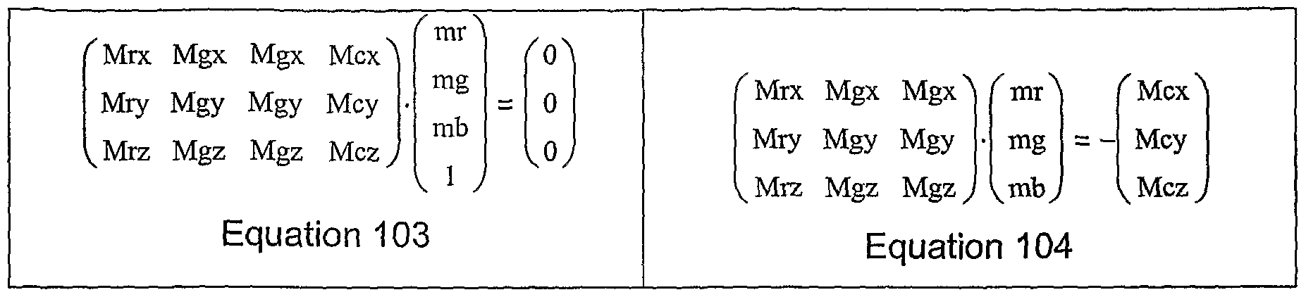
[0056] Equation 100 states a linear assumption: If one starts with some arbitrary RGBC color [r g b c], add a small number 'a' times the set of metamer slope values [mr mg mb me] and then convert to CIE XYZ with the M2X matrix, one will get the same CIE XYZ color after converting the original arbitrary color directly to CIE XYZ. The following process will calculate these metamer slope values. Equation 100 can be simplified by distribution, subtracting common terms from both sides, and dividing both sides by 'a' with the result in Equation 101. In the case of a four primary system, the M2X matrix may be a 4x3 matrix as shown in Equation 102 with the constant values Mrx, Mgx, etc.
[0057] In merely one embodiment, in order to find the m slope values, one might start by arbitrarily setting one of the m slope values to 1 (or some other convenient value) as shown in Equation 101. This is shown in Equation 103 with the M2X matrix expanded from Equation 102.
Figure imgf000017_0001
[0058] Because one of the slopes (the me slope for cyan) has been set to one (1), this may result in a column of constants in the result which can be subtracted from both sides. This is done in Equation 104. The remaining matrix on the left is square and the m slope values can be calculated by inverting the matrix and multiplying both sides by the result, as shown in Equation 105. It should be noted that other values besides one (1) will have a similar effect of producing a constant column.
Figure imgf000017_0002
Equation 105
[0059] This calculates the values of mr, mg, and mb when me is one (1). When the cyan primary of a color is changed by an amount ' a' , the other primaries should be changed by a*mr, a*mg and a*mb to create a metamer of the original color. It is possible to repeat the above procedure while arbitrarily setting a different slope constant to one (1), subtracting a different constant column from both sides, and solving for the remaining variables. Alternately, one may calculate the m slope values once as above, and then divide the set of slopes by each of the calculated slopes in turn to generate the set of slopes for each starting primary. An example of the M2X matrix for a test RGBC display is shown below with the m slope values for each primary as calculated by the above procedure.
Figure imgf000017_0003
[0060] Matrix 106 above is an example calculated from primary colorimetry and luminosity readings of a theoretical RGBC display. Matrix 107 is a table of metamer slope values to use when one knows how much one wishes to change red and needs to calculate how much to change the others. Matrix 108 shows how much to change the others when green is changed, Matrix 109 is when blue is changed and Matrix 110 is for when cyan is changed.
[0061] Two special cases are worth pointing out. As shown in some of the patent applications incorporated by reference, it is possible to make simplifying assumptions about the primaries and white point of a display - thus greatly simplify the design of the display system. When calculating the metamer slopes as above, there is one more variable that can be used to simplify designs of systems using metamers. The variable that can result in simplifications here is the relative luminosity of the primaries, hi one embodiment, such as the RGBW subpixel layout of Figures 3, 4, and 5 A, the luminosity of the W subpixel 304 is approximately equal to the combined brightness of the other three primaries 306, 308, and 310, or accounts for approximately half of the total luminosity of the display. If the following assumptions are made, the metamer m slope values have particularly easy values to implement:
1 The RGB primaries substantially match the Rec. 709 primaries.
2 The display produces a white point that substantially matches the D65 standard white point.
3 The relative luminosity of the RGB primaries is substantially the same as in a 3 primary RGB system with the same Rec. 709 and D65 assumptions.
4 The W sub-pixels account for one half of the total luminosity of each sub-pixel layout.
[0062] The assumptions yield a particular M2X matrix (shown below). If this M2X matrix is used in the procedure above to calculate the metamer slope values when changing the W primary, this results in a particularly convenient set of values as shown below:
Figure imgf000019_0001
[0063] Thus, if W is changed by any amount, it may only suffice to change the other primaries by the opposite amount to generate a metamer for the starting color. From this set, it is easy to see that changing one of the RGB primaries requires changing the other color primaries by the same amount and the W primary by the opposite amount.
[0064] In another embodiment, such as the case of the RGBW layout Figure 6 (with repeating subpixel grouping 620 comprising red 606, green 608, blue 610 and white 604 subpixels), the white 604 subpixel has approximately one third of the total brightness of subpixel group 620. As a result, the white subpixel is equal to approximately one half of the remaining 2/3 's of the luminosity. This relationship allows another convenient implementation in either hardware or software. For example, if one replaces assumption Number 4 above with:
4 The W sub-pixel accounts for one third of the total luminosity of each sub-pixel layout.
[0065] From this, one may calculate the M2X matrix and metamer slope values and the result is:
Figure imgf000019_0002
[0066] Thus, if one changes W by any amount, one may change the other primaries by half that amount in the opposite direction to generate a metamer for the starting color. Conversely, if one changes one of the color primaries by any amount, then this requires changing the other color primaries by the same amount and the W primary by twice the amount in the opposite direction. It should be noted that calculating half or double any amount can easily be done in hardware with a minimum of gates and therefore a minimum of expense. There is, of course, some degree of freedom in implementing such change. For example, one could change the values of all of the subpixels within a repeating group to affect the desired result. Alternatively, only half of the red 606 and the green 608 subpixels may be adjusted within a given repeating group 620 to affect the desired change. One possible advantage for performing the change on one half of the available subpixels within a group might be for hardware optimization. For example, fewer gates or less memory may be needed if the changes could occur on a same line of output data - as opposed to multiple lines of output data.
[0067] It should also be noted that, in an RGBW layout such as that shown in Figure 6, the blue 610 sub-pixel may contribute less to the luminosity than the Rec. 709 and D65 assumptions above would suggest. If this dimming of blue was taken into account then a different set of m slope values would result that may be more accurate but may not be as easy to implement in hardware.
[0068] All the above metamer slope calculations assumed a display with only four (4) primaries. As mentioned above, similar procedures can be made to work with any number of primaries. However, once the number of primaries is five (5) or more, the step in Equation 105 may need to be changed because the remaining matrix is no longer square and may not be inverted. There are several procedures that still allow the generation of useful metamer slope numbers. A non-invertible matrix does not mean that there is no solution to the problem; it means that there are many solutions. Only one solution may be suitable to generate usable sets ofmetamers.
[0069] In multi-primary systems larger than four, there will be an equation like Equation 101 that has more than four m slope values. One approach to solving these would be to set more than one of the m slopes to arbitrary values. When only three m slope values remain, then the subsequent steps may contain a square matrix that may then be inverted. The choice of values to use need not be completely arbitrary. For example, in a five primary high brightness wide gamut RGBCW (red, green, blue, cyan, and white) system it might be reasonable to assume that red and cyan are complimentary colors and should change in opposite directions so one (1) for the mw slope value and negative one (-1) for the me slope values may be a good place to start.
[0070] In a six primary system like that of Figure 7 (with a subpixel repeating group 701 comprising red 706, green 708, blue 710, cyan 707, magenta 709, and yellow 711 subpixels), since blue and green can combine to make cyan, one could set the mg and mb slope values to negative one (-1) while setting the me slope to 1. Choosing different values besides negative one (-1) for the complimentary primaries may result in other solutions. It may be advantageous to change the arbitrary values until a "convenient" set of metamer slopes is found that is easier to implement in hardware.
[0071] Another solution to solving for m slope values in multi-primary systems greater than four would be to use a numerical solver. This is actually similar to the previous discussion but with a computer algorithm choosing arbitrary values until a set that works is found. Many numerical solver packages are available, one that has been shown to work is the solver built into the Matlicad program by Mathsoft Engineering & Education, Inc. A numerical solver like this has a drawback that it may choose an undesirable solution. However, these packages allow one to set multiple constraint equations to avoid this. For example, constraining the solver from setting any of the slopes to zero, from choosing slopes greater than two (2), making sure that complimentary colors have opposite sign slopes, etc.
[0072] To simplify controller hardware designs, it may be desirable to adjust the size and/or brightness of the sub-pixels to produce convenient metamer slope values. The layouts of Figures 3 and 6, for example, resulted in metamer slopes that were 1 or powers of two. In the layout of Figure 7, the size of the cyan 707 magenta 709 and yellow 711 sub-pixels may be resized in relation to red, green and blue (due to their larger wavelength bandpass) until the metamer slope solutions are convenient numbers, such as: one half, one, two or other suitable numbers easy to implement in hardware.
[0073] In an alternate embodiment, these sub-pixels could remain substantially the same size as the other sub-pixels - e.g. if the ratio of the brightness of the CYM primaries to the RGB primaries have a convenient value. The example of the layout of Figure 6 shows that a ratio of 2: 1 can produce metamer slopes that are all 1 or 1A. Other ratios may produce other convenient metamer slope values. [0074] In other embodiments, adjusting the brightness of the different primaries may produce these simplifying results. One possible way of decreasing the brightness of a primary would be to increase the saturation. As the color of a primary becomes more pure - e.g. as the band pass filter becomes more narrow ~ the luminosity of the primary becomes lower. This adjustment can be done in the design of a display to produce "convenient" metamer slopes while at the same time increasing the total gamut of the display.
Metamer Filtering:
[0075] On the RGBW system having the subpixel repeating grouping 320, as shown in Figure 3, the layout could be seen as a checker board of white alternating with color (or more precisely, two checkerboards - one of blue and white subpixels and another of red and green subpixels). In subpixel rendering on this layout, one could perform a version of area resample subpixel rendering - such as 'One-Pixel-to-Two-Subpixel' mapping. In such a rendering, one input pixel may be mapped to a white 304 and blue 310 subpixel pair, such as pair 401 as shown in Figure 4, and the surrounding alternating input pixels may be mapped to a green 308 and red 306 subpixel pair (e.g. 406).
[0076] The freedom to select a color from among various metamers creates a new possibility to improve images. A display can be designed to select metamers in such a way that the W subpixel values are increased when they lie on the bright side of a high-frequency edge or decreased when they lie on the dark side of high-frequency edges. When red 306 and green 308 subpixel pairs 406 fall on the bright side of a high-frequency edge, it maybe desirable to select a metamer such that the R and G subpixel values are increased. Conversely, when the subpixel pair 406 lies on the dark side of an edge the R and G subpixel values should be decreased. The B subpixel does not contribute significantly to brightness and does not need to be considered.
[0077] The discussion above implies that different, perhaps opposite, filtering operations should be done on subpixel pairs 401 and subpixel pairs 406. The two filters below are one embodiment of these filters: WB mapped pixel RG mapped pixel
0 -x/4 0 O x/4 0
a = -x/4 x -χ/4 a = x/4 -x x/4
0 -x/4 0 O x/4 0
[0078] The value of "x" may be adjusted as a scale factor of this operation. The value x = 0.5 is an example of a suitable value but other values may also be chosen. It should be noted that the sign of the filter is reversed for the RG color vs. white subpixel locations. This may lead to several hardware or software optimizations. For example, using one filter but inverting the sign of the result on every other output subpixel pair. These filters resemble orthogonal sharpening filters from the art, however they are convolved with the L or luminance channel of the multi-primary data and not the color channels. The calculation of L is often done as a step in the GMA and it may be advantageous to save this value for later processing steps. This saved L value is shown between GMA module 102 and Line Buffers 104 in Figures IA and IB.
[0079] hi a prior art sharpening filters, the resulting 'a' value of the filter operation is eventually stored back in the pixel centered under the filter. However, in metamer filtering the center 'a' value is used instead to modify the metamer of the center pixel with the following equations:
W = W + a; R = R- mr*a; G = G- mg*a; B = B - mb*a;
[0080] The mr, mg and mb constants are the metamer slope values. As described above with the layout of Figure 3, these slope values may all have the value one (1) -- making the calculations easy to perform. It may be advantageous to set the default value of the metamer such that the W value equals the highest valued colored primary, or as close as possible to it. This will allow for the greatest "head-room" for the metamer filtering operation. One possible method of performing this metamer adjustment is disclosed in co- pending patent application, entitled SYSTEMS AND METHODS FOR IMPLEMENTING IMPROVED GAMUT MAPPING ALGORITHMS (US Serial Number 11/278,675, US Published Patent Application Number 200X/XXXXXXX - herein incorporated by reference in its entirety) and is shown in Figure IB as metamer select module 101.
[0081] Figure 11 is a high level diagram of one embodiment of metamer filtering. The system may operate on two sets of data, luminance data 1102 and image (or color) data 1104. These data sets may be coincident spatially - e.g. 1102 is the luminance data of image data 1104. Luminance channel 1102 is sampled for high frequency information with a filter kernel 1110. This filter kernel is described above for use on the BW sub-pixel pairs of Figure 3. In Figure 11, the value of x may be chosen to be 0.5 and the resulting coefficients may be calculated as 1A and minus 1/8. This filter may be applied to a 3x3 area centered on a BW pixel 1106. The result is a sharpening value 'a' — which is used to change the metamer of a color in step 1112. For each value 1106 in the luminance channel 1102, there is a corresponding R G B and W value 1108 shown diagrammatically in the color channels 1104. The RGBW values have their metamer changed in step 1112. The resulting metamer 1116 is stored in output buffer 1114 or passed on to the next step of processing.
[0082] In Figure 12, the RG sub-pixel pairs are processed in a similar fashion but with the opposite filter kernel, as described above. Values centered on an RG sub pixel pair 1206 are sampled from the luminance channel 1202 and convolved with filter kernel 1210. The resulting sharpness value 'a' is used in step 1212 to calculate a new metamer for an RGBW value 1208 from the color channels 1204. The resulting new metamer 1216 is stored in output buffer 1214 or passed on to the next step of processing.
[0083] It will be appreciated that Figures 11 and 12 are offered for explanation purposes and that other embodiments are possible. As mentioned above, different high spatial frequency data may be obtained ~ other than luminance data (e.g. red and/or green color data or the like). Other filter masks could be employed to obtain different values that reflect other relationships between the metamers (e.g. non-linear relationship, or other dimensions e.g. 5x5, or the like). It will also be appreciated that techniques and methods disclosed herein are not limited to operating with metamers in an RGBW space as depicted in Figures 11 and 12; but encompasses a multitude of mappings from one color space to another as discussed above. It would also be appreciated that for different subpixel layouts, there may be more than two subgroups of subpixels upon which different metamer filters would operate.
[0084] Figures 14 and 15 are other embodiments of display systems that may incorporate the techniques shown in Figures 11 and 12. Figure 14 is a flowchart of the preconditioning metamer filtering. If not already available, luminance may be calculated in step 1404 from the input data values 1402. Both the input values and luminance values may be stored in line buffers 1406. Line buffers or some other storage device such as a frame buffer may be desirable because filtering operations may look at the surrounding values. In software implementations where memory is readily available, it may be possible to store entire images in frame buffers. In hardware implementations, it is possible to build line buffers that hold 2 or more lines of values that may suffice for the filter. Such a line buffer may use fewer gates and may thus be desirable for lowering the cost of manufacture. Line buffer 1406 supplies the surrounding luminance values to the metamer filters. As described above, one filter kernel may be used for source pixels that will eventually be converted to BW sub-pixel pairs, as shown in #1 metamer filter 1408. Also as described above, a different filter kernel, shown as #2 metamer filer 1410, may be used for input pixels that will eventually be converted to RG sub-pixel pairs. The sharpening values that result from the metamer filters is used in step 1412 to modify the metamer of input colors. Line buffer 1406 is constructed to present the RGBW value of the input data pixel that corresponds to the luminance value that is in the center of the metamer filters 1408 and 1410. Of course, BW and RG metamers for an RGBW space are all exemplary descriptions. Systems may employ different metamer filters sets -- e.g. #1 Metamer Filter 1408 and #2 Metamer Filter 1410 and as many other filter sets as desired according to the input and output color spaces being mapped - as well as the topology of the target subpixel layout.
[0085] In the case of pre-conditioning metamer filtering, the adjusted pixel values may be stored in a second frame buffer or 2nd set of line buffers 1414. This is a normal part of sub-pixel rendering (SPR) which is also a filtering operation and may utilize a buffer to supply the surrounding values to a filter kernel. The output from line buffer 1414 is supplied to SPR filtering step 1416 which calculates values for output display 1418. [0086] Figure 15 is a flowchart of pre-conditioning metamer filtering when Difference of Gaussian (DOG) sharpening is also desirable. This flowchart is similar to Figure 14 with the following differences. In Figure 15, the luminance values from line buffer 1506 may be also retained and stored in the second line buffer 1514. This second line buffer presents the luminance information to DOG filter 1518 at the same time that the adjusted input values are presented to SPR filter 1516. The results are summed at step 1520 before output to display at step 1522
Metamer Filtering and Other Subpixel Rendering Techniques Combined:
[0087] For another exposition and to better understand the value of this technique, but without limiting the scope of the attached claims, imagine that there are spatial frequency components of the luminance signal in the diagonal direction of an achromatic (i.e. black & white) image. This signal would be attenuated by the area resample SPR if the same midpoint metamer selection occurred. But in this new case, with metameric pre-filtering, the energy would be pre-sharpened and partially or completely cancel the filtering of the SPR, all without excessive chromatic error.
[0088] To see this advantage, it is helpful to review the techniques of area resampling and conventional sharpening filters. Area resampling and conventional sharpening filters for this layout and others are previously disclosed in "IMPROVED SUBPIXEL RENDERING FILTERS FOR HIGH BRIGHTNESS SUBPIXEL LAYOUTS" (US Published Patent Application 2005/0225563 herein incorporated by reference) and also in CONVERSION OF A SUB-PIXEL FORMAT DATA TO ANOTHER SUB-PIXEL DATA FORMAT (US 2003/003.4992 herein incorporated by reference) and in FOUR COLOR ARRANGEMENT OF EMITTERS FOR SUBPIXEL RENDERING (US 2004/0051724 herein incorporated by reference). Consider the arrangement of RGBW subpixels in Figure 3, the red 306, green 308, and blue 310 subpixels are grouped 506 together, as shown in Figure 5A, in such a manner as to be considered a single reconstruction point 506B as shown in Figure 5B. The white 304 subpixel is in another group, as its sole occupant per group, considered as another reconstruction point 501 A. Together, these two sets of reconstruction points 501 A & 506B form a checkerboard of white vs. color reconstruction points. These reconstruction points 501 A and 506B may be mapped to incoming pixels 509 with their associated implied sample areas 511 on a one-pixel-to-one-reconstruction-point basis as shown in Figure 5C. Isolating just the white reconstruction points 5011 in Figure 5D, one can construct area resample areas 520 associated with each reconstruction point 5011. Such a resample area 520 may be defined, in one embodiment, by the area closest to its associated reconstruction point 5011, and where the boundaries may be defined by the set of lines equidistant from other neighboring reconstruction points. Thus, a given white reconstruction point 501 IA has an associated resample area 521. It also may have an associated polygonal (or other suitable shape) sharpening area 531, as defined by lines drawn between vertices at the nearest neighboring reconstruction points 501 IB of the same color.
[0089] In Figure 5E, the input pixels 509 may be mapped to the reconstruction points 5011 and resampled by the resample areas 520. A given resample area 521 associated with a given reconstruction point 501 IA overlaps five input pixels 509. As disclosed in the applications mentioned above, these areas give rise to fractions of the total area to generate the area resample based filter kernel given below:
0 .125 0 .125 .5 .125
0 .125 0
[0090] Although it is possible to generate an approximate DOG sharpening filter by inspection on such a simple example here, it is instructive to proceed using the area resample filter construction method. A given sharpening area 531 overlaps nine incoming pixels, generating the sharpening area resample filter below
.0625 .125 .0625
.125 .25 .125
.0625 .125 .0625
[0091] To calculate an approximate Difference Of Gaussians sharpening filter wavelet, the sharpening area filter kernel may be subtracted (e.g. by taking the difference) from the area resample filter kernel: 0 .125 0 .0625 .125 .0625 -.0625 0 -.0625
.125 .5 .125 - .125 .25 .125 0 .25 0
0 .125 0 .0625 .125 .0625 -.0625 0 -.0625
Area Resample - Sharpening Area = DOG Wavelet
[0092] In one embodiment, the RGBW metamer filtering may tend to pre-sharpen, or peak, the high spatial frequency luminance signal, with respect to the subpixel layout upon which it is to be rendered, especially the diagonally oriented frequencies, before the area resample filter blurs the image as a consequence of filtering out chromatic image signal components which may alias with the color subpixel pattern. The area resample filter tends to attenuate diagonals more than horizontal and vertical signals. The Difference of Gaussians (DOG) Wavelet ~ which may operate from the same color plane as the area resample, from another color plane, or from the luminance data plane —sharpens and maintains the horizontal and vertical spatial frequencies more than the diagonals. This exemplary DOG wavelet operation may be viewed as moving intensity values along same color subpixels in the diagonal directions while the metamer filtering operation moves intensity values across different color subpixels.
[0093] In comparison, the RGBW metamer filtering tends to sharpen the diagonals more than the horizontal and vertical signals, while area resampling tends to attenuate diagonals more than the horizontal and vertical signals. In fact, they may be proportionally complementary to each other when the RGBW metameric filter operator is set approximately to x = 0.5. Thus, in combination they serve to render the image with the full signal energy of the original image -- without the need for a DOG wavelet.
[0094] However, it may be advantageous to use a DOG wavelet to further sharpen the image - e.g. as shown in Figures 15 and 17. One embodiment uses a DOG wavelet to increase the modulation transfer function of the less luminous primaries such that they better contribute, in proportion, to the rendering of the luminance signal. Restated with a variable in an exemplary DOG wavelet: - z/4 0 -z/4 0 .125 0
0 Z 0 + .125 .5 .125
- z/4 0 - z/4 0 .125 0
DOG Wavelet + Area Resample
[0095] The less luminous primaries may be sharpened with a higher amplitude DOG filter. That is to say, that the z value is higher for darker primaries. For example, the white subpixel is the brightest and thus could be used as the normalizing brightness. Thus the z values might be determined by:
zw = s(Yw/Yw - l) = 0 zg = s(Yw/Yg - l) zr = s(Yw/Yr - l) zb = s(Yw/Yb - l) ; where Yw, Yg, Yr, and Yb are the luminance values (either approximated, modeled, measured or the like) of each fully "on" white, green, red, and blue primary respectively, zw, zg, Zn, Zb are the "z" values for sharpening the white, green, red, and blue subpixels respectively, in descending order of brightness for convenience and "s" is a scaling factor for the level of sharpening desired.
[0096] The white color plane could be sharpened along with the dimmer primaries using the DOG wavelet by replacing the constant with a number less than one.
[0097] In rendering band-limited images, it may be advantageous to interpolate values for half of the subpixels, taking advantage of the "extra" subpixel per pixel in the horizontal (higher subpixel density) direction using a suitable interpolation filter such as a sine, windowed sine, or Catmul-Rom cubic filter or other filter known now or to be later developed in the art. For example, the luminance, red, and the blue color planes may be interpolated between the original samples before being used by the above DOG wavelet and area resampling filters. The white and the green color planes would remain as before. Such filtering operations have been previously described in "IMPROVED SUBPIXEL RENDERING FILTERS FOR HIGH BRIGHTNESS SUBPIXEL LAYOUTS" (US Patent Application Publication 2005/0276502) and incorporated herein by reference. An example of a useful interpolation filter is the Catmul-Rom cubic filter:
1/ 9/ 9/ 1 /
" / 16 / 16 ' 16 " / 16
[0098] Rather than performing the metameric filtering as a preconditioning step, it is possible to construct SPR so that it directly performs the metameric filtering in a single pass. For example, if one incoming pixel were mapped to a single white subpixel 304 as shown in Figure 5A, and the surrounding input pixels were mapped to the red, green, and blue subpixels as a group (e.g. group 506), centered on the green subpixels, then a single filter set maybe used for all four color planes. As merely for example, shown below is a set of such direct filters where the metameric filter coefficient x = 0.5 :
Area Resampling the Self Color Plane: Sampling the Luminance Plane:
0 .125 0 0 -.125 0
.125 .5 .125 + -.125 .5 -.125
0 .125 0 0 -.125 0
[0099] Although it is possible to generate an approximate metameric sharpening filter by inspection on such a simple example here, it is instructive to proceed using the area resample filter construction method. In Figure 5F, the white 5011 and color 5066 luminance reconstruction points are shown overlain on the incoming pixels 509 and their associated implied sample areas 511. The luminance resample areas 525 substantially coincide with the implied sample areas 511 of the incoming pixels 509. A given reconstruction point, in this example, a white reconstruction point 501 IA, has an associated luminance sample area 526, substantially coincident with an implied sample area 511 of an incoming pixel 509. Thus, the luminance sample area overlaps substantially one implied sample area and results in an approximate unity filter with a value of one (1). As shown, luminance reconstruction point 501 IA may also have an associated polygonal metameric sharpening sample area 536 defined by lines with vertices at the nearest neighbors of the opposite metamer exchange reconstruction points 5066A. This metameric sharpening sample area overlaps five implied pixel sample areas 511, generating the filter kernel below. To calculate the direct metameric filter kernel, the metameric sharpening area filter kernel may be subtracted from the luminance sample area filter kernel:
O O O O .125 O O -.125 O
O 1 O .125 .5 .125 -.125 .5 -.125
O O O O .125 O O -.125 O
Area Resample Sharpening Area = Metamer Sharpening Wa
[00100] It should be noted that a similar behavior occurs in the direct method and the metameric filter preconditioning, when an incoming pixel value (as 501) is mapped to white subpixel 304 and the incoming pixel value has more brightness than its surrounding pixels 506, the white subpixel 304 gets brighter, etc. The two methods may not produce identical results however. The result of the preconditioning operation followed by subpixel rendering is a convolution of the two operations. The output intensity value of a given subpixel is affected by the input luminance value of pixels that surround the four nearest neighbors, while the direct metameric filtering operation does not exhibit this behavior. This suggests that the metameric preconditioning filter method may be suited to band-limited images while the direct method isisuitable for both band-limited and non-band-limited images, performing particularly well on black on white text when the metameric filter operator is set approximately to x = 0.5 as shown above. As before, other values for the operator are possible.
[00101] It is also possible to construct a direct metameric filter that maps the white and blue subpixel to the same incoming pixel as a group. However, when this is done, the metameric filter may have the reverse sign as shown below. This may have the effect of blurring the blue image component. This may be reversed with a high amplitude sharpening DOG wavelet added to the self-color area resampling filter also shown below. The red, green, and white color planes continue to be filtered as above. Sampling the Self Color Plane: Sampling the Luminance Plane
-.125 .125 -.125 0 .125 0
.125 1 .125 + .125 -.5 .125
-.125 .125 -.125 0 .125 0
[00102] Figures 16 and 17 are two embodiments of systems that combine the features of metamer filtering with subpixel rendering - called direct metamer filtering for the purposes of this application. In Figures 14 and 15, it can be seen that two frame buffers or line buffers are described. Both of these line buffers are intended for holding and organizing information to supply the values needed for a filtering operation. However, in direct metamer filtering, the two filtering operations are combined together and only one line buffer or frame buffer may suffice. This results in a significant savings of memory requirements in software implementations or a significant savings of gates in hardware implementations, hi addition, only one metamer filter kernel is necessary instead of a separate one for BW vs. RW pairs of output sub-pixels. Figure 16 shows this embodiment. If they are not already available from previous steps, luminance values are calculated in step 1604 from input pixel values 1602. The input values and luminance values are stored in line buffers 1606. Line buffers 1606 present the color input values to the SPR filter 1608 and the luminance information to metamer filter 1610. The results from the two filters is summed at step 1612 and sent to the output display 1614 or sent to the next step in processing.
[00103] Figure 17 shows the direct metamer filtering algorithm of Figure 16 with the addition of DOG filtering when additional sharpening of the image is desirable. The luminance values from line buffer 1706 are used in an additional DOG filter step 1712. The output from this DOG filter 1712 is summed with the output from SPR filter 1708 and metamer filter 1710 in the summing step 1714. The result of summer 1714 is sent to output display 1716 or to the next processing step, hi another embodiment, it may be possible to combine metamer filter 1710 and DOG filter 1712 into one pre-calculated filter kernel.
[00104] For another embodiment, the layout in Figure 6 has one white 604 subpixel per repeat cell 620 of six subpixels (i.e, comprising red 606, green 608, blue 610 and white 604 subpixels as shown). The white 604 subpixel is in half of the rows, the RWG rows 625, while a single blue subpixel is found on the other rows, the GBR rows 635. To offset or reverse the blurring effect of the area resample filter on the white 604 subpixel, a direct metameric filter may be constructed:
Sampling the White Color Plane: Sampling the Luminance Plane
-.015625 .140625 .140625 -.015625 -.125 -.125
-.03125 .28125 .28125 -.03125 + .25 .25
-.015625 .140625 .140625 -.015625 -.125 -.125
[00105] The white plane may be sampled with an area resample filter that has been modified to have Catmul-Rom cubic type interpolation in the horizontal axis. For band- limited images, this interpolation may increase the image quality, taking advantage of the white 604 subpixel's interstitial position between the red/green columns on either side. The luminance plane may be sampled with a direct metameric filter, concentrating intensity in the white subpixel when the pixels mapped to the RWG row 625 have more luminance than the two GBR rows 635 above and below said RWG row 625, etc. The red 606 and green 608 subpixels in the RWG row 625 do not use a metameric filter:
Area Resampling the Self Color Plane: Sampling the Luminance Plane:
0 .125 0 -.0625 0 -.0625
.125 .5 .125 + 0 .25 0
0 .125 0 -.0625 0 -.0625
[00106] The above filter is an area resample filter with a DOG sharpening filter. While the red 606 and green 608 subpixels in the RWG rows 625 do not have metameric filters, the red 606 and green 608 in the GBR rows 635 do. The red 606 subpixel filter may be as follows: Area Resampling the Red Color Plane: Sampling the Luminance Plane:
0 .125 0 -.125 -.0625 -.0625
.125 .5 .125 + .125 .375 0
0 .125 0 -.125 -.0625 -.0625
[00107] The green 608 subpixel filter may be as follows:
Area Resampling the Green Color Plane: Sampling the Luminance Plane:
0 .125 0 -.0625 -.0625 -.125
.125 .5 .125 + 0 .375 .125
0 .125 0 -.0625 -.0625 -.125
[00108] Examination and comparison of the two filters sampling the luminance plane will reveal that the second filter is a DOG sharpening filter with a metameric filter added. This metameric filter is the counter part to the white subpixel metameric filter.
[00109] The blue 610 subpixel presents two choices, hi one embodiment, it may have the counterpart filter to the white 604 subpixel, using substantially the same metameric filter. For band-limited images, this may be an advantageous choice to ensure color accuracy. However, for non-band-limited images, especially black text on white, the blue 610 subpixel may represent the blue component of the rows 625 above and below as well as in line 635. In one embodiment, it need not use the metameric filter, leaving the blue image "fuzzy", which would tend to match the lower resolution of the human vision system, and that for non-band- limited images, the image has less color error without the metameric filter.
[00110] With metameric filtering on this layout in Figure 6, horizontally oriented lines and spaces may appear sharper, but vertically aligned lines and spaces may still appear to be "fuzzy" and "dotty". A simple technique, while not being a metameric operation, may improve the appearance of vertically orientated lines and spaces. Just as metameric filters are directed by the local entropy and sign of the luminance signal at a point in the image to select a better metamer at that point, the following contrast improvement procedure given below measures the entropy, regardless of the sign, to push down the intensity of the white subpixel. This may have the tendency to increase the contrast of black on white text and of natural images, in a manner similar to that explained in detail in the application entitled "METHODS AND SYSTEMS FOR SUB-PIXEL RENDERING WITH GAMMA ADJUSTMENT". The equation is:
W = W - | (Lr - Lg)/2 | where Lr and Lg are the luminance values of the pixel mapped to the red 606 subpixel and the green 608 subpixel on either side of the white 604 subpixel respectively.
[00111] In the RGBW system, one possible metameric degree of freedom is W vs. RGB. hi other four color systems such as RGBC, where the primaries are red, green, blue, and cyan respectively there is also one possible degree of metameric freedom that is roughly RC vs. GB. Another four color system may be RGCM, where the primaries are red, green, cyan, and magenta respectively; there is one possible degree of freedom that is RC vs. GM. Another four color system would be RGBY, where the primaries are red, green, blue and yellow respectively, where one possible degree of metameric freedom is roughly RG vs. Y. Other metameric pairs and degrees of freedom are also possible as well.
[00112] In all of the figures presented herein, such additional subpixel layouts may be obtained by replacing all or some of the white subpixels with either cyan, yellow, grey or other colors, as the case may be. In particular, the techniques discussed herein may be employed with the layout of Figures 2, 3, 4, 5, 6, 9 A and 10 with all or some of the white subpixels with either cyan, yellow, grey or other colors. In addition, the techniques discussed herein encompass the scope of all manners of display technologies, including transmissive and non-transmissive display panels, such as Liquid Crystal Displays (LCD), reflective Liquid Crystal Displays, emissive ElectroLuminecent Displays (EL), Plasma Display Panels (PDP), Field Emitter Displays (FED), Electrophoretic displays, Iridescent Displays (ID), Incandescent Display, solid state Light Emitting Diode (LED) display, and Organic Light Emitting Diode (OLED) displays.
[00113] A five color system such as RGBCW, where the primaries are red, green, blue, cyan, and white respectively, there are two possible degrees of metameric freedom that is roughly RC vs. GB and W vs. RGBC. A six color system such as RGBCYM, where the primaries are red, green, blue, cyan, yellow, and magenta have even more degrees of freedom such as RC vs. YB vs. GM and RGB vs. CYM. One can imagine any arbitrarily high number N of primaries in a display which may give N-3 degrees of freedom to select a metamer. Each degree of freedom in a multiprimary system is an opportunity for a metameric filter, either for metameric preconditioning or direct metameric filtering to be constructed and used to improve the subpixel rendering system.
[00114] In Figure 8, a square group of four subpixels 802 is shown, comprised of four primaries. In this arrangement, each primary is on a hexagonal grid with the same relationship of neighboring primaries. If the primaries are chosen such that each column has a pair of primaries that are exactly or roughly metameric pairs with the alternating columns, then the construction of a metameric filter, either sequential metameric filter preconditioning or direct metameric filtering type, may proceed as follows.
[00115] First, determine the Area Resample and DOG filters for the layout, using the methods that have been disclosed in the above listed prior applications to create an approximate filter set. For one embodiment, it may be:
Area Resampling the Self Color Plane: Difference of Gaussians:
0 0 Z/
- /6 0 0
Figure imgf000036_0001
.125 .25 .125 +
0 0 Z 0 0 .0625 .125 .0625 Z/ Z/
0 0 0 - /6
0 0 Z/ - P. 0 0
[00116] The DOG filter above may be generated from simple examination. As before, the DOG filter may sample either the self color plane, another color plane, or the luminance plane, as the DOG filter transfers signal intensities between same color subpixels. The value of "z" may be adjusted per color as explained earlier, with the brightest primary serving as a reference.
[00117] Examining the layout 800 in Figure 8 for a metamer filter, it should be noted that the colors in each column 825 and 835 may move together as the metamers are adjusted. Thus, moving energy along a column 825 and 835 does not provide as much value as moving energies from the neighboring columns. Thus, the metamer filter may be as shown here:
-x/6 o -V6 -V3 x -V3 -V6 o -V6
[00118] The result of this filter may be used to adjust the values directly as a metameric filter, perhaps combined with the DOG filter above, if the metamers have the same coefficients such as for RGCM primaries, or used to push the metamer values in a metameric filter preconditioning operation before subpixel rendering by the Area Resample + DOG filter above if the metamer coefficients are not the same, such as for RGBC primaries. Of course the indirect, preconditioning method would change the signs for the filters for each alternating column 825 and 835.
[00119] Examining Figure 2 (with repeating group 202 comprising white 204, red 206, green 208, blue 210 and fifth color 212) and Figure 10 (with repeating group 1002 comprising white 1004, red 1006, green 1008, blue 1010 and fifth color 1012) we note that there are five primaries, with four of them at a lower resolution on the same hexagonal grid as the four primaries in Figure 8. Figure 9 A (with repeating group 902 comprising white 904, red 906, green 908, blue 910 and fifth color 912) has an arrangement similar to Figure 2 save that the four lower resolution primaries are arranged in rows instead of columns. Each of these layouts in Figures 2, 9 A, and 10, may use similar subpixel rendering and metameric filters for the lower resolution primaries as just described for the layout shown in Figure 8, with allowance made for rotation of the filters for Figure 9 A. However, in these layouts, an additional, higher resolution primary is present (e.g. 204, 904, 1004). This additional primary may be a bright color primary such as yellow, white, or grey.
[00120] Although it is possible to generate an approximate DOG sharpening filter for a hex arrangement of saturated color subpixels by inspection or examination as was done above, it is instructive to proceed using the strict area resample filter construction method. Examining Figure 9B, which shows the one of the satuarated color primary reconstruction points 9122 overlain and mapped on an array of pixels 909 and their implied sample areas 925. A given saturated primary reconstruction point 9122 A has associated resample area 926 and sharpening area 936, generating the following filter kernels: 0 0 0 0 0 0 7 11 7 0 0 -7 -11 -7 0
0 12 40 12 0 1 20 21 20 1 -1 -8 19 -8 -1
0 32 64 32 0 8 21 22 21 8 = -8 11 42 11 -8
0 12 40 12 0 1 20 21 20 1 -1 -8 19 -8 -1
0 0 0 0 0 0 7 11 7 0 0 -7 -11 -7 0
AreaResample Sharpening Area = DOG Wavelet
Note that the coefficients are divided by 256.
[00121] As noted earlier, a five primary display may have additional degrees of freedom in which to select a metamer to best render a given image at the subpixel level. Assuming that these layouts are RGBCW systems, there are at least two degrees of freedom available, W vs. RGBC and RC vs. GB. Both degrees of freedoms may be used in the same image to improve rendering accuracy. For merely one example, assume that a vertically oriented line of a pastel color, that is to say, not white but still substantially de-saturated is to be rendered onto a dark grey background onto the display of either Figure 2 or Figure 10. In that case, the desired metamer may maximize the intensity of the white plane on the line and reduce it on either side, in response to a W vs. RGBC metameric filter. Further, the desired metamer may maximize the intensity of the metameric pair in a column, either RC or GB, upon which the bright vertical line is to be drawn and reduce the intensity of the columns on either side, in response to an RC vs. GB metameric filter.
[00122] A W vs. RGBC metameric filter preconditioning operation may proceed similarly to that described earlier for the W vs. RGB system:
Samples the Luminance Plane:
Figure imgf000038_0001
X/ X/
- /8 X - /8 = a
Figure imgf000038_0002
Then modifies the RGBCW values of each pixel:
W = W + a;
R = R - a;
G = G - a;
B - B - a;
C = C - a
And samples the luminance plane for the RC vs. GB metamers: R and C mapped pixels G and B mapped pixels
-V6 o -V6 V6 o V6
-V3 x -V3 V3 -x V3 = a
-V6 o -V6 V6 o V6
Then modifies the RGBCW values of each pixel:
W = W;
R = R + a*mr;
G = G- a*mg;
B = B - a*mb;
C = C + a*mc where mr, mg, mb, and me are metameric 'm' slope coefficients that scale the effect of the value of "a" for each color, red, green, blue, and cyan respectively to maintain the desired color through the metameric adjustment.
[00123] It should be noted that in one set of formula above where the W primary is changed, there may be no metamer slope terms. When modifying the W vs the color primaries, this may be treated as another special case where the metamer slope terms all simplify to plus or minus one if the correct assumptions can be made, as described in the section above about calculating metamers.
[00124] These operations may be substantially commutative, meaning they might be done in either order. After the metamer precondition, the data may be subpixel rendered. The white subpixel planes may be sampled to the fully one-pixel-to-one-white-subpixel mapped layout using a unity filter, a 1 X 1 array with the single filter coefficient value of one (1). The lower resolution colored primaries on a hexagonal grid may be area resampled and sharpened with a DOG using the filters disclosed earlier. Further, since the colored subpixels are displaced at interstitial points, it may be advantageous for rendering band-limited images using a suitable interpolating reconstruction filter, such as those discussed above. The layouts of Figure 2 and 9 may use a single horizontally oriented Catmul-Rom cubic filter, while the layout in Figure 10 may use a Catmul-Rom bicubic filter, either as an axis separable operation or as a convolved operation, as is understood in the art, on the color data planes to shift the phase of the reconstructed image before the subpixel rendering.
[00125] Examining Figure 7, the layout 700 shown is comprised of a six subpixel repeat cell 701 of six primaries, RGBCMY; substantially red 706, green 708, blue 710, cyan
707, magenta 709, and yellow 711 respectively. This collection of primaries exhibits a number of degrees of freedom as discussed above; RC vs. GM vs. BY and RGB vs. CMY. In this example, the three sets of pairings of two colors that form dichromatic metamers for white are arranged in columns; red 706 and cyan 707 are in a first column 726, green 708 and magenta 709 are in a second column 728, and blue 710 and yellow 711 is in a third column 730. The two sets of trichromatic metamers for white are arranged in columns; red 706, green
708, and blue 710 are in a first row 725, and cyan 707, magenta 709, and yellow 711 are in a second row 735. These columns and rows are repeated across a display as many times as are desired to complete a given desired resolution panel, as known in the art. An additional feature is that the sizes of the subpixels may be adjusted such that the two trichromatic pairs for white are substantially the same luminance, hi this example, the red 706, green 708, and blue 710 are twice as tall as the cyan 707, magenta 709, and yellow 711 as these colors generally are half the luminance when constructed as filters over a broad spectrum emitter or reflector as is found in backlit Liquid Crystal Displays, reflective Liquid Crystal Displays, and filtered white emitting Organic Light Emitting Diode displays (OLED). Other display technologies may exhibit other ratios and may be adjusted accordingly as desired. This feature allows each row 725 and 735 to render a white horizontal line with equal luminance.
It should also be noted that the dichromatic metameric pair in the columns 726, 728, and 730 may also exhibit equal luminance, allowing each said column to render a vertical line with equal luminance.
[00126] One-Pixel-to-One-Subpixel rendering filters for the layout 700 may be constructed as: Area Resampling the Self Color Plane:
1/ 1/ 1/ /12 /12 /12
1/ 1/ 1/ /6 /6 /6
1/ 1/ 1/
/12 /12 /12
[00127] The RGB vs. CMY metameric preconditioning filters, sampling the luminance (L) plane may be constructed: RGB Rows 725 CMY Rows 735
X/ X/ X/ x/
- /6 " /6 " /6 V6 V6 /6
Figure imgf000041_0001
X/ X/ X/ x/6 V6 x/
- '6 " /6 " /6 /6
Then modifies the RGBCMY values of each pixel: R = R + a G = G + a B = B + a C = C-a M = M-a
Y = Y-a
[00128] The RC vs. GM vs. BY metameric preconditioning filters, sampling the luminance (L) plane may be constructed: o V4 -V4 -V4 V4 o
0 x/2 -V2 = d -V2 V2 0 = e
0 V4 -V4 -V4 V4 0
Then modifies the RGBCMY values of each pixel mapped to the RC columns 726:
R=R+d+e
G = G-d
B = B-e
C=C+d+e
M = M-d
Y = Y-e Then modifies the RGBCMY values of each pixel mapped to the GM columns 728:
R = R- e
G = G + d + e
B = B - d
C = C - e
M = M + d + e
Y = Y - d Then modifies the RGBCMY values of each pixel mapped to the BY columns 728:
R = R- d
G = G - e
B = B + d + e
C = C - d
M = M - e
Y = Y + d + e
[00129] As before, the values of 'x' may be adjusted as desired. It should be noted that there may be no need of slope value in order to create metamers. This is the result of the additional feature that the sizes of the subpixels 707, 709 and 711 were adjusted such that the two trichromatic pairs for white are substantially the same luminance. Of course, if the subpixels were of equal size and/or dimension, appropriate slope values could be created in accordance with the principles and techniques described herein.
[00130] In some applications where the illustrated display systems and techniques may find use, the Gamut Mapping function may have already been performed by an another component or system; or the multiprimary image may have been captured directly from a multispectral camera, that is, one that captures images in four or more spectral bands that lie in or even outside the normal human vision system range of spectral wavelengths. For example, an RGBC multiprimary display may reconstruct images captured on an RGBC camera. In such cases, it may advantageous to calculate the luminance "L" value for use by the subpixel rendering and metameric filters, as this value may not be supplied directly by the input image, hi the case of a display, the formula for calculating the luminosity can be derived from the specifications of the display, from measurements, or from the M2X matrix for that display. In the case of a multi-spectral camera, the formula could be derived from the specification or from measurements from pictures taken of test patterns of known spectral ramps. If the camera has substantially the same multiple primaries as a multi-primary display in the same system, then it would be advantageous to make the simplifying assumption that the primaries and relative luminosities of the display and camera are identical. This will simplify the math, the resulting software or hardware designs and thus decrease the total complexity and cost of the total system.
[00131] While the display systems and image processing methods have been described with reference to exemplary embodiments, it will be understood by those skilled in the art that various changes may be made and equivalents may be substituted for elements thereof without departing from the scope of the attached claims. In addition, many modifications maybe made to adapt a particular situation or material to the teachings without departing from the essential scope thereof. Therefore, it is intended that the invention not be limited to the particular embodiment disclosed as the best mode contemplated for carrying out this invention, but that the invention will include all embodiments falling within the scope of the appended claims.

Claims

CLAIMS What is claimed is:
1. A display system comprising: a display, said display comprising at least a first set of subpixels and a second set of subpixels further comprising at least one metamer; an input image data unit; a spatial frequency detection unit, said spatial frequency detection unit extracting a spatial frequency characteristic from said input image data; and an adjustment unit, said adjustment unit adjusting image data of said first set and said second set of subpixels according to said spatial frequency characteristic.
2. The display system of Claim 1 wherein said display further comprises a display further comprising at least a first set of subpixels and a second set of subpixels, said first set of subpixels and said second set of subpixels capable of producing a metamer rendered upon said display.
3. The display system of Claim 1 wherein said spatial frequency detection unit further comprises one of a group, said group comprising: a filter, an adaptive filter, an edge detector, a flat field detector, a blurring filter and a transform detector.
4. The display system of Claim 1 wherein said characteristic comprises high spatial frequency luminance values.
5. The display system of Claim 1 wherein said adjustment unit further comprises a metamer slope adjustment.
6. In a display system comprising a display wherein said display further comprises a subpixel repeating group, said group comprising at least one metamer further comprising at least a first set of colored subpixel and a second set of colored subpixels, a method for adjusting image data for rendering onto said display, the steps of said method comprising: inputting image data into said display system; extracting luminance data from said image data; adjusting intensity values between said first set of subpixels and said second set of subpixels according to a relationship based upon said luminance data; and outputting said adjusted image data to said display.
7. The method of Claim 6 wherein the step of extracting the luminance data further comprising calculating said luminance data directly from input image data.
8. The method of Claim 6 wherein the step of extracting the luminance data further comprises approximating the luminance data from high brightness colored subpixels.
9. The method of Claim 6 wherein the step of adjusting intensity values between said first set of subpixels and said second set of subpixels further comprises: applying a filter to the luminance data, said filter capable of calculating spatial frequency data in said luminance data.
10. The method of Claim 9 wherein the step of adjusting intensity values between said first set of subpixels and said second set of subpixels further comprises calculating a adjustment value from said spatial frequency data in said luminance data, said adjustment value being used to adjust the image data between said first set and said second set of subpixels.
11. The method of Claim 10 wherein the said adjustment value is a sharpness value for sharpen regions of high spatial frequency information.
12. The method of Claim 10 wherein the said adjustment value is a smoothness value for smoothing image data.
13. The method of Claim 6 wherein the steps of adjusting intensity values between said first set of subpixels and said second set of subpixels further comprises introducing random noise to improve grey scale performance.
14. The method of Claim 6 wherein the steps of adjusting intensity values between said first set of subpixels and said second set of subpixels further comprises introducing random noise to reduce quantization error.
15. In a display system comprising a display wherein said display further comprises a subpixel repeating group, said group comprising at least one metamer further comprising of at least a first set of colored subpixel and a second set of colored subpixels, a method for adjusting intensity values between said first set and said second set of subpixels to minimizing image artifacts, the steps of said method comprising: modeling the behavior of changing intensity values between said first set and said second set of subpixels; storing intensity adjustment values comprising said model in said display system; and employing said intensity adjustment values to adjust said first set and second set of subpixels.
16. The method of Claim 15 wherein the step of modeling the behavior of changing intensity values further comprises determining metamer slope values from a relationship of the chromaticity and luminosity of the primaries comprising said first set and said second set of subpixels.
17. The method of Claim 16 wherein the step of employing said intensity adjustment values further comprises multiplying said metamer slope values by an amount of change in intensity of at least one of the subpixel in said first set of subpixels.
18. The method of Claim 16 wherein the step of determining metamer slope values further comprises setting the metamer slope value of at least one of the subpixel to a convenient value to employ square matrix calculation of the remaining slope values.
19. The method of Claim 15 wherein further the display is an RGBW display and said metamer slope values comprise: 1 for W and -1 for R, G and B subpixels respectively.
20. The method of Claim 15 wherein further the display is an RGBW display and said metamer slope values comprise: 1 for W and -0.5 for R, G and B subpixels respectively.
21. A display system comprising: a display, said display further comprising a subpixel repeating group, said group comprising at least one metamer further comprising of at least a first set of colored subpixels and a second set of colored subpixels; an optional luminance calculation unit for calculating luminance values from input image data; a plurality of metamer filters for producing an adjustment value based upon a relationship of said luminance values; a metamer adjustment unit for adjusting the intensity of said first and second sets of subpixels according to said adjustment value.
22. The display system of Claim 21 where said display system further comprises: a subpixel rendering unit to subpixel render image data after said image data is metamer adjusted.
23. The display system of Claim 21 where said display system further comprises: a subpixel rendering unit to subpixel render image data concurrently as said image data is metamer adjusted.
24. The display system of Claim 22 or 23 wherein said subpixel rendering unit performs area resampling of said image data.
25. The display system of Claim 23 or 24 wherein said display system further comprises a difference of Gaussian filter unit.
PCT/US2006/019657 2005-05-20 2006-05-19 Multiprimary color subpixel rendering with metameric filtering WO2006127555A2 (en)

Priority Applications (6)

Application Number Priority Date Filing Date Title
US11/914,587 US7787702B2 (en) 2005-05-20 2006-05-19 Multiprimary color subpixel rendering with metameric filtering
JP2008512585A JP5070204B2 (en) 2005-05-20 2006-05-19 Multiple primary color sub-pixel rendering with metamer filtering
EP06770785.1A EP1882234B1 (en) 2005-05-20 2006-05-19 Multiprimary color subpixel rendering with metameric filtering
KR1020077025760A KR101254032B1 (en) 2005-05-20 2006-05-19 Multiprimary color subpixel rendering with metameric filtering
CN2006800171598A CN101176108B (en) 2005-05-20 2006-05-19 Multiprimary color subpixel rendering with metameric filtering
US12/835,644 US8081835B2 (en) 2005-05-20 2010-07-13 Multiprimary color sub-pixel rendering with metameric filtering

Applications Claiming Priority (4)

Application Number Priority Date Filing Date Title
US68318005P 2005-05-20 2005-05-20
US60/683,180 2005-05-20
US74717706P 2006-05-12 2006-05-12
US60/747,177 2006-05-12

Related Child Applications (2)

Application Number Title Priority Date Filing Date
US11/914,587 A-371-Of-International US7787702B2 (en) 2005-05-20 2006-05-19 Multiprimary color subpixel rendering with metameric filtering
US12/835,644 Continuation US8081835B2 (en) 2005-05-20 2010-07-13 Multiprimary color sub-pixel rendering with metameric filtering

Publications (2)

Publication Number Publication Date
WO2006127555A2 true WO2006127555A2 (en) 2006-11-30
WO2006127555A3 WO2006127555A3 (en) 2007-03-22

Family

ID=37452671

Family Applications (1)

Application Number Title Priority Date Filing Date
PCT/US2006/019657 WO2006127555A2 (en) 2005-05-20 2006-05-19 Multiprimary color subpixel rendering with metameric filtering

Country Status (7)

Country Link
US (2) US7787702B2 (en)
EP (2) EP1882234B1 (en)
JP (1) JP5070204B2 (en)
KR (1) KR101254032B1 (en)
CN (1) CN101176108B (en)
TW (1) TWI343027B (en)
WO (1) WO2006127555A2 (en)

Cited By (16)

* Cited by examiner, † Cited by third party
Publication number Priority date Publication date Assignee Title
WO2008144180A1 (en) 2007-05-18 2008-11-27 Samsung Electronics Co., Ltd. Image color balance adjustment for display panels with 2d subpixel layouts
US7505053B2 (en) 2004-04-09 2009-03-17 Samsung Electronics Co., Ltd. Subpixel layouts and arrangements for high brightness displays
EP2051235A2 (en) 2007-10-19 2009-04-22 Samsung Electronics Co., Ltd. Adaptive backlight control dampening to reduce flicker
EP2051229A2 (en) 2007-10-09 2009-04-22 Samsung Electronics Co., Ltd. Systems and methods for selective handling of out-of-gamut color conversions
JP2009282977A (en) * 2008-05-19 2009-12-03 Samsung Electronics Co Ltd Input gamma dithering system and method
CN101996600A (en) * 2009-08-24 2011-03-30 三星电子株式会社 Gamut mapping which takes into account pixels in adjacent areas of display unit
DE102010009291A1 (en) * 2010-02-25 2011-08-25 Expert Treuhand GmbH, 20459 Method and apparatus for an anatomy-adapted pseudo-holographic display
US8159509B2 (en) 2007-03-30 2012-04-17 Oki Semiconductor Co., Ltd. Color display device and method for reproducing color with an increased number of gradation levels
US8203582B2 (en) 2009-08-24 2012-06-19 Samsung Electronics Co., Ltd. Subpixel rendering with color coordinates' weights depending on tests performed on pixels
US8228357B2 (en) 2009-07-29 2012-07-24 Samsung Electronics Co., Ltd. Generation of subpixel values and light source control values for digital image processing
JP2012151832A (en) * 2007-02-13 2012-08-09 Samsung Electronics Co Ltd Subpixel layouts and subpixel rendering methods for directional displays and systems
US8405672B2 (en) 2009-08-24 2013-03-26 Samsung Display Co., Ltd. Supbixel rendering suitable for updating an image with a new portion
JP5244174B2 (en) * 2008-05-27 2013-07-24 シャープ株式会社 Signal conversion circuit and multi-primary color liquid crystal display device including the same
US9117398B2 (en) 2012-03-16 2015-08-25 Samsung Display Co., Ltd. Data rendering method, data rendering device, and display including the data rendering device
US9792877B2 (en) 2013-04-12 2017-10-17 Samsung Display Co., Ltd Data processing device and display system including the same
US10319339B2 (en) 2013-11-26 2019-06-11 Focaltech Systems, Ltd. Data transmission method, processor and terminal

Families Citing this family (93)

* Cited by examiner, † Cited by third party
Publication number Priority date Publication date Assignee Title
KR101287039B1 (en) * 2005-10-14 2013-07-23 삼성디스플레이 주식회사 Improved gamut mapping and subpixel rendering system and method
KR101191451B1 (en) * 2006-06-09 2012-10-18 엘지디스플레이 주식회사 LCD and drive method thereof
CN101529496B (en) * 2006-10-19 2012-01-11 皇家飞利浦电子股份有限公司 Color mapping method, system and display device
JP2008270936A (en) * 2007-04-17 2008-11-06 Nec Electronics Corp Image output device and image display device
EP2156709A4 (en) * 2007-04-24 2010-05-05 Lg Chemical Ltd Organic light-emitting display apparatus and method for driving the same
US20100149393A1 (en) * 2008-05-22 2010-06-17 Panavision Imaging, Llc Increasing the resolution of color sub-pixel arrays
JP5204563B2 (en) * 2008-06-24 2013-06-05 パナソニック株式会社 LED lighting device
US8466856B2 (en) 2011-02-22 2013-06-18 Global Oled Technology Llc OLED display with reduced power consumption
JP5493438B2 (en) * 2009-04-10 2014-05-14 株式会社ニコン Projector and projected image correction program
CN101924869B (en) * 2009-06-11 2012-09-26 联咏科技股份有限公司 Image processing circuit and method
TWI416488B (en) * 2009-09-14 2013-11-21 Au Optronics Corp Compensation method for pixel data, timing controller and liquid crystal display
JP5187351B2 (en) * 2010-06-17 2013-04-24 株式会社ニコン Projector and projected image correction program
US8659585B2 (en) 2009-10-16 2014-02-25 Nikon Corporation Projector apparatus and projection image correcting program product
JP5317948B2 (en) * 2009-12-16 2013-10-16 株式会社ジャパンディスプレイウェスト Image display device, driving method thereof, and program
KR101588336B1 (en) * 2009-12-17 2016-01-26 삼성디스플레이 주식회사 Method for processing data and display apparatus for performing the method
TW201142807A (en) 2010-05-20 2011-12-01 Chunghwa Picture Tubes Ltd RGBW display system and method for displaying images thereof
US20110285713A1 (en) * 2010-05-21 2011-11-24 Jerzy Wieslaw Swic Processing Color Sub-Pixels
US20120287148A1 (en) * 2011-05-13 2012-11-15 Candice Hellen Brown Elliott Method and apparatus for improved subpixel rendering
US9338445B2 (en) 2011-08-04 2016-05-10 Dolby Laboratories Licensing Corporation Method and apparatus for full resolution 3D display
GB2495317A (en) * 2011-10-06 2013-04-10 Sharp Kk Image processing method for reduced colour shift in multi-primary LCDs
GB2496113A (en) * 2011-10-28 2013-05-08 Sharp Kk Multiple view window multi-primary display
TWI459810B (en) 2011-11-22 2014-11-01 Altek Corp Image processing apparatus and processing method thereof
JP6035940B2 (en) * 2012-07-23 2016-11-30 セイコーエプソン株式会社 Image processing apparatus, display apparatus, and image processing method
US8941678B2 (en) * 2012-07-27 2015-01-27 Eastman Kodak Company Display system providing observer metameric failure reduction
US9172933B2 (en) * 2012-10-17 2015-10-27 Samsung Display Co., Ltd. Correcting anamolous texture and feature width effects in a display that uses a multi primary color unit scheme
WO2014087963A1 (en) * 2012-12-05 2014-06-12 シャープ株式会社 Multi-primary color display device
KR102002986B1 (en) * 2013-01-11 2019-07-24 삼성디스플레이 주식회사 Display device and driving method of the same
US8879867B2 (en) * 2013-01-18 2014-11-04 Xerox Corporation Processing source video for real-time enhancement of a signal of interest
CN103280187B (en) * 2013-06-09 2015-12-23 上海和辉光电有限公司 Pixel list view method, device and OLED display
TWI501218B (en) 2013-07-05 2015-09-21 Novatek Microelectronics Corp Image display apparatus and image fine tuning method thereof
KR102085284B1 (en) 2013-07-05 2020-03-06 삼성디스플레이 주식회사 Display Device and Display Device Driving Method
CN104282230B (en) * 2013-07-10 2017-04-05 上海和辉光电有限公司 Pel array and the flat-panel screens with the pel array
KR20150008712A (en) 2013-07-15 2015-01-23 삼성디스플레이 주식회사 Signal processing method, signal processor, and display device comprsing the signal processor
KR102025184B1 (en) * 2013-07-31 2019-09-25 엘지디스플레이 주식회사 Apparatus for converting data and display apparatus using the same
KR102141542B1 (en) 2013-12-31 2020-09-14 엘지디스플레이 주식회사 Display device
US9598011B2 (en) * 2014-01-09 2017-03-21 Northrop Grumman Systems Corporation Artificial vision system
US9449373B2 (en) * 2014-02-18 2016-09-20 Samsung Display Co., Ltd. Modifying appearance of lines on a display system
CN104036710B (en) 2014-02-21 2016-05-04 北京京东方光电科技有限公司 Pel array and driving method thereof, display floater and display unit
CN104050889B (en) * 2014-05-30 2015-04-29 京东方科技集团股份有限公司 Display device and drive method
US9645436B2 (en) 2014-06-17 2017-05-09 Apple Inc. Color filter structures for electronic devices with color displays
CN104036701B (en) 2014-06-26 2016-03-02 京东方科技集团股份有限公司 Display panel and display packing, display device
CN104123904B (en) 2014-07-04 2017-03-15 京东方科技集团股份有限公司 Pel array and its driving method and display floater
JP2016024382A (en) * 2014-07-22 2016-02-08 株式会社ジャパンディスプレイ Image display device and image display method
US9454926B2 (en) * 2014-09-18 2016-09-27 Shenzhen China Star Optoelectronics Technology Co., Ltd. Image data processing method and device of using the same
US9691313B2 (en) 2014-09-30 2017-06-27 X Development Llc Display pixel structures and method of operating same
CN104375302B (en) * 2014-10-27 2020-09-08 上海中航光电子有限公司 Pixel structure, display panel and pixel compensation method thereof
TWI554805B (en) * 2014-12-12 2016-10-21 聯詠科技股份有限公司 Display panel
CN104485064B (en) * 2014-12-31 2017-03-15 深圳市华星光电技术有限公司 The method of the sub-pixel compensation coloring of the RGBW display devices detected based on edge pixel
KR20160092125A (en) * 2015-01-26 2016-08-04 삼성디스플레이 주식회사 Display apparatus
WO2016119860A1 (en) * 2015-01-29 2016-08-04 Hewlett-Packard Development Company, L.P. Processing an object for printing
KR20160097444A (en) 2015-02-06 2016-08-18 삼성디스플레이 주식회사 Display apparatus
US9953574B2 (en) * 2015-04-28 2018-04-24 Microsoft Technology Licensing, Llc Sub-pixel compensation
KR102320207B1 (en) * 2015-05-06 2021-11-03 삼성디스플레이 주식회사 Image corrector, display device including the same and method for displaying image using display device
TWI587006B (en) * 2015-06-30 2017-06-11 友達光電股份有限公司 Display device and head up display
JP2017040733A (en) * 2015-08-19 2017-02-23 株式会社ジャパンディスプレイ Display device
CN105609033A (en) * 2015-12-18 2016-05-25 武汉华星光电技术有限公司 Pixel rendering method, pixel rendering device and display device
GB201602272D0 (en) 2016-02-09 2016-03-23 Univ Manchester Improvements in image formation
US10600213B2 (en) * 2016-02-27 2020-03-24 Focal Sharp, Inc. Method and apparatus for color-preserving spectrum reshape
US10049425B2 (en) * 2016-05-23 2018-08-14 Google Llc Merging filters for a graphic processing unit
KR102589145B1 (en) 2016-10-04 2023-10-12 엘지전자 주식회사 Image display apparatus
CN108074539B (en) 2016-11-08 2020-10-20 联咏科技股份有限公司 Electronic device, display driver and display data generation method of display panel
TWI684967B (en) 2016-11-08 2020-02-11 聯詠科技股份有限公司 Image processing apparatus, display panel and display apparatus
TWI659405B (en) 2017-05-10 2019-05-11 聯詠科技股份有限公司 Image processing apparatus and method for generating display data of display panel
KR102330866B1 (en) * 2017-08-23 2021-11-24 엘지디스플레이 주식회사 Luminance Compensation System of Display Device and Its Luminance Compensation Method
CN108231845B (en) * 2018-01-02 2020-04-24 上海天马有机发光显示技术有限公司 Display panel and electronic equipment
US11410593B2 (en) 2018-10-25 2022-08-09 Baylor University System and method for a multi-primary wide gamut color system
US11030934B2 (en) 2018-10-25 2021-06-08 Baylor University System and method for a multi-primary wide gamut color system
US11475819B2 (en) 2018-10-25 2022-10-18 Baylor University System and method for a multi-primary wide gamut color system
US10950162B2 (en) 2018-10-25 2021-03-16 Baylor University System and method for a six-primary wide gamut color system
US11373575B2 (en) 2018-10-25 2022-06-28 Baylor University System and method for a multi-primary wide gamut color system
US11069280B2 (en) 2018-10-25 2021-07-20 Baylor University System and method for a multi-primary wide gamut color system
US11189210B2 (en) 2018-10-25 2021-11-30 Baylor University System and method for a multi-primary wide gamut color system
US10607527B1 (en) 2018-10-25 2020-03-31 Baylor University System and method for a six-primary wide gamut color system
US11043157B2 (en) 2018-10-25 2021-06-22 Baylor University System and method for a six-primary wide gamut color system
US11532261B1 (en) 2018-10-25 2022-12-20 Baylor University System and method for a multi-primary wide gamut color system
US11037481B1 (en) 2018-10-25 2021-06-15 Baylor University System and method for a multi-primary wide gamut color system
US11488510B2 (en) 2018-10-25 2022-11-01 Baylor University System and method for a multi-primary wide gamut color system
US11315467B1 (en) 2018-10-25 2022-04-26 Baylor University System and method for a multi-primary wide gamut color system
US11587491B1 (en) 2018-10-25 2023-02-21 Baylor University System and method for a multi-primary wide gamut color system
US11341890B2 (en) 2018-10-25 2022-05-24 Baylor University System and method for a multi-primary wide gamut color system
US11069279B2 (en) 2018-10-25 2021-07-20 Baylor University System and method for a multi-primary wide gamut color system
US10950161B2 (en) 2018-10-25 2021-03-16 Baylor University System and method for a six-primary wide gamut color system
US11062638B2 (en) 2018-10-25 2021-07-13 Baylor University System and method for a multi-primary wide gamut color system
US11289003B2 (en) 2018-10-25 2022-03-29 Baylor University System and method for a multi-primary wide gamut color system
US10997896B2 (en) 2018-10-25 2021-05-04 Baylor University System and method for a six-primary wide gamut color system
US11403987B2 (en) 2018-10-25 2022-08-02 Baylor University System and method for a multi-primary wide gamut color system
US11289000B2 (en) 2018-10-25 2022-03-29 Baylor University System and method for a multi-primary wide gamut color system
CN111710287B (en) * 2020-03-20 2022-09-09 利亚德光电股份有限公司 Image display method, system and storage medium
CN111696447A (en) * 2020-03-20 2020-09-22 利亚德光电股份有限公司 Dot matrix LED display screen, method and system for displaying image and storage medium
CN113961026B (en) * 2020-10-27 2022-09-30 深圳职业技术学院 Environmental illumination simulation system based on multi-primary-color spectrum superposition process
CN113160751B (en) * 2021-04-21 2022-07-26 晟合微电子(肇庆)有限公司 Sub-pixel rendering method of AMOLED display panel
US11501419B1 (en) 2021-06-03 2022-11-15 Baylor University System and method for displaying super saturated color
US11816819B2 (en) 2021-06-03 2023-11-14 Baylor University System and method for displaying super saturated color

Citations (7)

* Cited by examiner, † Cited by third party
Publication number Priority date Publication date Assignee Title
US5161202A (en) 1990-07-18 1992-11-03 Dainippon Screen Mfg. Co. Ltd. Method of and device for inspecting pattern of printed circuit board
US20030034992A1 (en) 2001-05-09 2003-02-20 Clairvoyante Laboratories, Inc. Conversion of a sub-pixel format data to another sub-pixel data format
US6536904B2 (en) 2000-12-30 2003-03-25 Texas Instruments Incorporated Reduced color separation white enhancement for sequential color displays
US20030085906A1 (en) 2001-05-09 2003-05-08 Clairvoyante Laboratories, Inc. Methods and systems for sub-pixel rendering with adaptive filtering
US20030103058A1 (en) 2001-05-09 2003-06-05 Candice Hellen Brown Elliott Methods and systems for sub-pixel rendering with gamma adjustment
US20040196302A1 (en) 2003-03-04 2004-10-07 Im Moon Hwan Systems and methods for temporal subpixel rendering of image data
US6885380B1 (en) 2003-11-07 2005-04-26 Eastman Kodak Company Method for transforming three colors input signals to four or more output signals for a color display

Family Cites Families (49)

* Cited by examiner, † Cited by third party
Publication number Priority date Publication date Assignee Title
US2432601A (en) 1942-12-12 1947-12-16 Du Pont Polymers of alpha-methylene cyclic acetals
JPH0837604A (en) * 1994-05-17 1996-02-06 Olympus Optical Co Ltd Image processor
JP3155996B2 (en) * 1995-12-12 2001-04-16 アルプス電気株式会社 Color liquid crystal display
US6750875B1 (en) * 1999-02-01 2004-06-15 Microsoft Corporation Compression of image data associated with two-dimensional arrays of pixel sub-components
US7283142B2 (en) 2000-07-28 2007-10-16 Clairvoyante, Inc. Color display having horizontal sub-pixel arrangements and layouts
US7274383B1 (en) 2000-07-28 2007-09-25 Clairvoyante, Inc Arrangement of color pixels for full color imaging devices with simplified addressing
US8022969B2 (en) 2001-05-09 2011-09-20 Samsung Electronics Co., Ltd. Rotatable display with sub-pixel rendering
JP2004524729A (en) 2000-12-12 2004-08-12 シャープ株式会社 Display resolution enhancement method and system using sub-pixel sampling and visual distortion filtering
US6801220B2 (en) * 2001-01-26 2004-10-05 International Business Machines Corporation Method and apparatus for adjusting subpixel intensity values based upon luminance characteristics of the subpixels for improved viewing angle characteristics of liquid crystal displays
JP2003006630A (en) * 2001-06-19 2003-01-10 Fujitsu Ltd Device and method for displaying color image
US20030117423A1 (en) 2001-12-14 2003-06-26 Brown Elliott Candice Hellen Color flat panel display sub-pixel arrangements and layouts with reduced blue luminance well visibility
US20040051724A1 (en) 2002-09-13 2004-03-18 Elliott Candice Hellen Brown Four color arrangements of emitters for subpixel rendering
US7583279B2 (en) 2004-04-09 2009-09-01 Samsung Electronics Co., Ltd. Subpixel layouts and arrangements for high brightness displays
US7417648B2 (en) 2002-01-07 2008-08-26 Samsung Electronics Co. Ltd., Color flat panel display sub-pixel arrangements and layouts for sub-pixel rendering with split blue sub-pixels
US7492379B2 (en) 2002-01-07 2009-02-17 Samsung Electronics Co., Ltd. Color flat panel display sub-pixel arrangements and layouts for sub-pixel rendering with increased modulation transfer function response
JP2004034224A (en) 2002-07-03 2004-02-05 Honda Motor Co Ltd Work assembling fixture
TW200405082A (en) * 2002-09-11 2004-04-01 Samsung Electronics Co Ltd Four color liquid crystal display and driving device and method thereof
US20040080479A1 (en) 2002-10-22 2004-04-29 Credelle Thomas Lioyd Sub-pixel arrangements for striped displays and methods and systems for sub-pixel rendering same
US7046256B2 (en) 2003-01-22 2006-05-16 Clairvoyante, Inc System and methods of subpixel rendering implemented on display panels
DE602004014250D1 (en) * 2003-01-28 2008-07-17 Genoa Color Technologies Ltd SUBPIXEL ARRANGEMENT FOR DISPLAYS MORE THAN THREE PRIMARY COLORS
US6917368B2 (en) 2003-03-04 2005-07-12 Clairvoyante, Inc. Sub-pixel rendering system and method for improved display viewing angles
US7167186B2 (en) 2003-03-04 2007-01-23 Clairvoyante, Inc Systems and methods for motion adaptive filtering
US7352374B2 (en) 2003-04-07 2008-04-01 Clairvoyante, Inc Image data set with embedded pre-subpixel rendered image
US20040233308A1 (en) 2003-05-20 2004-11-25 Elliott Candice Hellen Brown Image capture device and camera
US7230584B2 (en) 2003-05-20 2007-06-12 Clairvoyante, Inc Projector systems with reduced flicker
US7417601B2 (en) 2003-05-20 2008-08-26 Samsung Electronics Co., Ltd. Projector systems
US7268748B2 (en) 2003-05-20 2007-09-11 Clairvoyante, Inc Subpixel rendering for cathode ray tube devices
US7397455B2 (en) 2003-06-06 2008-07-08 Samsung Electronics Co., Ltd. Liquid crystal display backplane layouts and addressing for non-standard subpixel arrangements
US7187353B2 (en) 2003-06-06 2007-03-06 Clairvoyante, Inc Dot inversion on novel display panel layouts with extra drivers
US7218301B2 (en) 2003-06-06 2007-05-15 Clairvoyante, Inc System and method of performing dot inversion with standard drivers and backplane on novel display panel layouts
US8035599B2 (en) 2003-06-06 2011-10-11 Samsung Electronics Co., Ltd. Display panel having crossover connections effecting dot inversion
US20040246280A1 (en) 2003-06-06 2004-12-09 Credelle Thomas Lloyd Image degradation correction in novel liquid crystal displays
US7791679B2 (en) 2003-06-06 2010-09-07 Samsung Electronics Co., Ltd. Alternative thin film transistors for liquid crystal displays
US7209105B2 (en) 2003-06-06 2007-04-24 Clairvoyante, Inc System and method for compensating for visual effects upon panels having fixed pattern noise with reduced quantization error
US6897876B2 (en) * 2003-06-26 2005-05-24 Eastman Kodak Company Method for transforming three color input signals to four or more output signals for a color display
DE10335870A1 (en) 2003-08-06 2005-03-17 Tahles Atm Gmbh Surveillance system for terrestrial navigation and landing systems
US7176935B2 (en) 2003-10-21 2007-02-13 Clairvoyante, Inc. Gamut conversion system and methods
US7598961B2 (en) 2003-10-21 2009-10-06 Samsung Electronics Co., Ltd. method and apparatus for converting from a source color space to a target color space
US6980219B2 (en) 2003-10-21 2005-12-27 Clairvoyante, Inc Hue angle calculation system and methods
US7728846B2 (en) 2003-10-21 2010-06-01 Samsung Electronics Co., Ltd. Method and apparatus for converting from source color space to RGBW target color space
US7084923B2 (en) 2003-10-28 2006-08-01 Clairvoyante, Inc Display system having improved multiple modes for displaying image data from multiple input source formats
US7525526B2 (en) 2003-10-28 2009-04-28 Samsung Electronics Co., Ltd. System and method for performing image reconstruction and subpixel rendering to effect scaling for multi-mode display
US7495722B2 (en) * 2003-12-15 2009-02-24 Genoa Color Technologies Ltd. Multi-color liquid crystal display
US7268758B2 (en) 2004-03-23 2007-09-11 Clairvoyante, Inc Transistor backplanes for liquid crystal displays comprising different sized subpixels
US7619637B2 (en) 2004-04-09 2009-11-17 Samsung Electronics Co., Ltd. Systems and methods for improved gamut mapping from one image data set to another
US7301543B2 (en) 2004-04-09 2007-11-27 Clairvoyante, Inc. Systems and methods for selecting a white point for image displays
US7825921B2 (en) 2004-04-09 2010-11-02 Samsung Electronics Co., Ltd. System and method for improving sub-pixel rendering of image data in non-striped display systems
US7248268B2 (en) 2004-04-09 2007-07-24 Clairvoyante, Inc Subpixel rendering filters for high brightness subpixel layouts
US7590299B2 (en) 2004-06-10 2009-09-15 Samsung Electronics Co., Ltd. Increasing gamma accuracy in quantized systems

Patent Citations (7)

* Cited by examiner, † Cited by third party
Publication number Priority date Publication date Assignee Title
US5161202A (en) 1990-07-18 1992-11-03 Dainippon Screen Mfg. Co. Ltd. Method of and device for inspecting pattern of printed circuit board
US6536904B2 (en) 2000-12-30 2003-03-25 Texas Instruments Incorporated Reduced color separation white enhancement for sequential color displays
US20030034992A1 (en) 2001-05-09 2003-02-20 Clairvoyante Laboratories, Inc. Conversion of a sub-pixel format data to another sub-pixel data format
US20030085906A1 (en) 2001-05-09 2003-05-08 Clairvoyante Laboratories, Inc. Methods and systems for sub-pixel rendering with adaptive filtering
US20030103058A1 (en) 2001-05-09 2003-06-05 Candice Hellen Brown Elliott Methods and systems for sub-pixel rendering with gamma adjustment
US20040196302A1 (en) 2003-03-04 2004-10-07 Im Moon Hwan Systems and methods for temporal subpixel rendering of image data
US6885380B1 (en) 2003-11-07 2005-04-26 Eastman Kodak Company Method for transforming three colors input signals to four or more output signals for a color display

Non-Patent Citations (1)

* Cited by examiner, † Cited by third party
Title
See also references of EP1882234A4

Cited By (27)

* Cited by examiner, † Cited by third party
Publication number Priority date Publication date Assignee Title
US7583279B2 (en) 2004-04-09 2009-09-01 Samsung Electronics Co., Ltd. Subpixel layouts and arrangements for high brightness displays
US7505053B2 (en) 2004-04-09 2009-03-17 Samsung Electronics Co., Ltd. Subpixel layouts and arrangements for high brightness displays
EP3480649A1 (en) 2007-02-13 2019-05-08 Samsung Display Co., Ltd. Subpixel layouts and subpixel rendering methods for directional displays and systems
US8933959B2 (en) 2007-02-13 2015-01-13 Samsung Display Co., Ltd. Subpixel layouts and subpixel rendering methods for directional displays and systems
CN102809826A (en) * 2007-02-13 2012-12-05 三星电子株式会社 Subpixel layouts and subpixel rendering methods for directional displays and systems
JP2012151832A (en) * 2007-02-13 2012-08-09 Samsung Electronics Co Ltd Subpixel layouts and subpixel rendering methods for directional displays and systems
EP2733518A2 (en) 2007-02-13 2014-05-21 Samsung Display Co., Ltd. Subpixel layouts and subpixel rendering methods for directional displays and systems
EP3035111A1 (en) 2007-02-13 2016-06-22 Samsung Display Co., Ltd. Subpixel layouts and subpixel rendering methods for directional displays and systems
EP3176628A1 (en) 2007-02-13 2017-06-07 Samsung Display Co., Ltd. Subpixel layouts and subpixel rendering methods for directional displays and systems
US8159509B2 (en) 2007-03-30 2012-04-17 Oki Semiconductor Co., Ltd. Color display device and method for reproducing color with an increased number of gradation levels
US8456483B2 (en) 2007-05-18 2013-06-04 Samsung Display Co., Ltd. Image color balance adjustment for display panels with 2D subixel layouts
EP2147426A4 (en) * 2007-05-18 2011-03-09 Samsung Electronics Co Ltd Image color balance adjustment for display panels with 2d subpixel layouts
EP2147426A1 (en) * 2007-05-18 2010-01-27 Samsung Electronics Co., Ltd. Image color balance adjustment for display panels with 2d subpixel layouts
WO2008144180A1 (en) 2007-05-18 2008-11-27 Samsung Electronics Co., Ltd. Image color balance adjustment for display panels with 2d subpixel layouts
EP2051229A2 (en) 2007-10-09 2009-04-22 Samsung Electronics Co., Ltd. Systems and methods for selective handling of out-of-gamut color conversions
EP2051235A2 (en) 2007-10-19 2009-04-22 Samsung Electronics Co., Ltd. Adaptive backlight control dampening to reduce flicker
JP2009282977A (en) * 2008-05-19 2009-12-03 Samsung Electronics Co Ltd Input gamma dithering system and method
JP5244174B2 (en) * 2008-05-27 2013-07-24 シャープ株式会社 Signal conversion circuit and multi-primary color liquid crystal display device including the same
US8228357B2 (en) 2009-07-29 2012-07-24 Samsung Electronics Co., Ltd. Generation of subpixel values and light source control values for digital image processing
US8405672B2 (en) 2009-08-24 2013-03-26 Samsung Display Co., Ltd. Supbixel rendering suitable for updating an image with a new portion
US8223180B2 (en) 2009-08-24 2012-07-17 Samsung Electronics Co., Ltd. Gamut mapping which takes into account pixels in adjacent areas of a display unit
US8203582B2 (en) 2009-08-24 2012-06-19 Samsung Electronics Co., Ltd. Subpixel rendering with color coordinates' weights depending on tests performed on pixels
CN101996600A (en) * 2009-08-24 2011-03-30 三星电子株式会社 Gamut mapping which takes into account pixels in adjacent areas of display unit
DE102010009291A1 (en) * 2010-02-25 2011-08-25 Expert Treuhand GmbH, 20459 Method and apparatus for an anatomy-adapted pseudo-holographic display
US9117398B2 (en) 2012-03-16 2015-08-25 Samsung Display Co., Ltd. Data rendering method, data rendering device, and display including the data rendering device
US9792877B2 (en) 2013-04-12 2017-10-17 Samsung Display Co., Ltd Data processing device and display system including the same
US10319339B2 (en) 2013-11-26 2019-06-11 Focaltech Systems, Ltd. Data transmission method, processor and terminal

Also Published As

Publication number Publication date
US20090058873A1 (en) 2009-03-05
CN101176108A (en) 2008-05-07
JP2008546006A (en) 2008-12-18
EP2372609A2 (en) 2011-10-05
EP2372609A3 (en) 2011-11-30
CN101176108B (en) 2010-09-29
KR20080011659A (en) 2008-02-05
EP1882234B1 (en) 2019-01-02
WO2006127555A3 (en) 2007-03-22
EP1882234A4 (en) 2009-12-02
JP5070204B2 (en) 2012-11-07
US8081835B2 (en) 2011-12-20
KR101254032B1 (en) 2013-04-12
EP1882234A2 (en) 2008-01-30
TW200707328A (en) 2007-02-16
US20100277498A1 (en) 2010-11-04
US7787702B2 (en) 2010-08-31
TWI343027B (en) 2011-06-01

Similar Documents

Publication Publication Date Title
US8081835B2 (en) Multiprimary color sub-pixel rendering with metameric filtering
JP5190626B2 (en) Improved subpixel rendering filter for high brightness subpixel layout
JP5256283B2 (en) Image color balance adjustment for display panels with 2D sub-pixel layout
US7965305B2 (en) Color display system with improved apparent resolution
JP5411202B2 (en) Method for performing image reconstruction and sub-pixel rendering to perform scaling for multi-mode displays
EP2051229B1 (en) Systems and methods for selective handling of out-of-gamut color conversions
US20150235393A1 (en) Image device and data processing system
KR101999546B1 (en) Method of correcting colors, machine-implemented method for a multi-primary color matrix display apparatus, and imgae data signal processing apparatus
Elliott et al. Image Reconstruction on Color Sub-pixelated Displays

Legal Events

Date Code Title Description
WWE Wipo information: entry into national phase

Ref document number: 200680017159.8

Country of ref document: CN

121 Ep: the epo has been informed by wipo that ep was designated in this application
WWE Wipo information: entry into national phase

Ref document number: 7589/DELNP/2007

Country of ref document: IN

WWE Wipo information: entry into national phase

Ref document number: 2006770785

Country of ref document: EP

WWE Wipo information: entry into national phase

Ref document number: 1020077025760

Country of ref document: KR

ENP Entry into the national phase

Ref document number: 2008512585

Country of ref document: JP

Kind code of ref document: A

WWE Wipo information: entry into national phase

Ref document number: 11914587

Country of ref document: US

NENP Non-entry into the national phase

Ref country code: DE

NENP Non-entry into the national phase

Ref country code: RU