RETICLE FOR TELESCOPIC GUNSIGHT AND METHOD FOR USING
INCORPORATION BY REFERENCE
[0001] The following documents are incorporated herein by reference: 1. MALE MAGAZINE, November 1967, Article page 11, "The
Man who Refused To Die";
2. The Instruction manual previously entitled "The Perfect Shot" and currently titled "The TDS -TRI-FACTOR Mental Ballistics Calculator System," by Thomas D. Smith III; 3. The Instruction manual entitled "Tactical Stress Management," by Thomas D. Smith III;
4. The Instruction manual entitled "The TDS TRI-FACTOR Rifle Scope System" by Thomas D. Smith III; and
5. The Instruction manual entitled "The ADINO Combat Rifle Scope System" by Thomas D. Smith III.
BACKGROUND OF THE INVENTION
1. Field of Invention
[0002] This invention relates to telescopic and other optical sighting systems for use on guns and other projectile delivering systems of all types but will herein it will be described as primarily applied to telescopic sights on typical rifles. More particularly, this invention relates most naturally to a telescopic gunsight equipped with a transparent aiming reticle and a method for using that reticle on a gun but it is certainly not constrained to that specific application.
2. Description of Prior Art [0003] It is well known that the line of sight between a shooter's eye and a target is a straight line, whether using "iron" sights or a telescopic sight, while the trajectory of the projectile is never a straight line (when passing though a gravitational field, the trajectory follows a ballistic parabola), which becomes of particular importance for projectile flights covering long distances. Accordingly, in order to achieve sufficiently accurate shot placement, it is essential either to "sight in" the rifle (or other projectile delivering system: hereafter "gun") to produce the projectile (hereafter, bullet) to the desired aiming point at a specific fixed target distance or to know both the distance from the gun to the target and the trajectory characteristics of the bullet used. Trajectory characteristics for commercial bullets are related to initial launch velocity and are known or are easily obtained from either the manufacturer or from trajectory charts such as INGALLS' tables.
[0004] Telescopic gunsights, often referred to as "scopes," generally contain a transparent flat disk reticle positioned in a plane perpendicular to the line of sight through the scope. The reticle conventionally has a single vertical crosshair (or hairline) and a single horizontal crosshair (or hairline), which intersects the vertical hairline near the visual center of the reticle and the scope. The point of intersection of these crosshairs constitutes the primary sighting point for the scope, representing site of bullet impact at a chosen (zero) distance.
[0005] In modern scopes, the gunsight is most commonly moveable in vertical and horizontal directions by way of calibrated adjustment screws located on the scope exterior (internal adjustments); in some older and a few newer and new scopes, the gunsight is adjusted by devices within the scope attachment system (external
adjustments). Method of adjustment has no significant influence upon reticle design or use.
[0006] By firing one or more shots and making compensatory adjustments of the relative position of the reticle center point, the shooting system, which is comprised of rifle, bullet type and velocity, scope and shooter is "zeroed in" so that aiming position of the reticle crossed hairlines or reticle center point coincides with point of bullet impact on the target.
[0007] In certain scope sighting systems, the reticle has a series of evenly- spaced secondary horizontal hairlines that intersect the vertical hairline below the center horizontal hairline. In those systems, the respective points of intersection of the secondary hairlines with the vertical hairline are typically used to estimate bullet impact points at distances progressively greater than that at which the rifle was "zeroed in" with the main (center) horizontal crosshair. However, in order to utilize these secondary horizontal crosshairs with accurate and predictable results, the shooter must know distance from gun to target with a significant degree of precision.
[0008] Various types of range finder systems have been disclosed for telescopic gunsights. For example, U.S. Patent 1,190,121 to Critchett discloses a reticle having a series of target-spanning rulings disposed above a baseline, the rulings corresponding to associated shooting distances. In use, the shooter ascertains which ruling above the baseline makes the most closely embracing fit on the target, thereby determining the shooting distance (target range). A separate crosshair aiming point is included in the reticle for use in association with each chosen ruling above the baseline.
[0009] The principle of the Critchett target-spanning rulings is that certain targets are of known, or at least estimable size. For instance, it is a fairly accurate estimate that for mature deer or antelope, the distance between the top of the back at the shoulders and the bottom of the chest cavity is about 18 inches. The target- spanning rulings are spaced apart such as to span a known target size at a known range. This manner of distance measurement is consistent with conventional trigonometric considerations wherein the triangle defined by the height of the target and the viewing angle through the telescope's optical system can be considered a right
triangle, which accordingly establishes the length of the base line distance to the distal side of the triangle, namely the distance to the target.
[0010] U.S. Patent 3,392,450 to Herter et. al. discloses a reticle having a series of target-spanning circles of different diameters which correspond to associated shooting distances. Employing the same basic distance-measuring concept as
Critchett, the shooter employs for aiming purposes, that crosshair which corresponds to the selected circle.
[0011] U.S. Patent 3,190,003 to O'Brien concerns a range-finding reticle for a telescopic gunsight having single centered vertical and horizontal hairlines. The portion of the vertical hairline below the horizontal centerline is provided with widened bar regions extending various lengths below the centerline. Each bar subtends a target of known size. By finding which widened region corresponds to the height of the target, the shooting distance is estimated.
[0012] U.S. Patent 3,431,652 to Leatherwood discloses a telescopic gunsight wherein the distance to the target is determined by movement of upper and lower horizontal hairlines along a fixed vertical hairline in a manner so as to bracket the target. Once bracketed, the intersection of the lower horizontal hairline with the vertical hairline serves as the crosshair aiming point. In this aiming process, the alignment of the scope changes with respect to the gun barrel, whereby the allowance for distance is achieved when the centered crosshair is sighted directly on the target.
[0013] U.S. Patent 3,492,733 to Leatherwood discloses a distance measuring system for a variable power telescopic sight that is pivotally moveable in a vertical plane with respect to the gun barrel upon which it is mounted. Cams within the scope and rotatable by external means achieve vertical movement of the scope so that horizontal framing hairlines will fit the target. A specialized cam must be installed into the scope for each particular type of ammunition employed.
[0014] U.S. Patent 3,948,587 to Rubbert concerns a variable power telescopic sight having a reticle provided with a vertical hairline, a center horizontal hairline and three horizontal framing lines disposed below the center horizontal hairline. Aiming is achieved by positioning either the center crosshair or lower crosshairs on the target, as dictated by the observed fit of the target within the framing lines.
[0015] U.S. Patent 4,403,421 to Shepherd discloses a telescopic gunsight having spaced apart primary and secondary reticles which are moveable relative to each other. The secondary reticle is also moveable vertically and horizontally within the plane of the reticle. The moveable two reticle system facilitates adjustments for windage and elevation. Distance to the target is ascertained by framing indicia on the secondary reticle.
[0016] The telescopic sights disclosed in the aforementioned prior art patents are often of limited usefulness insofar as they do not address many of the several factors that need to be considered in the accurate aiming of a rifle under field conditions. Such factors include: a) distance to target b) drop of bullet caused by force of gravity c) hold-over or hold-under aiming points d) wind drift correction e) correction for phenomenon associated with gyroscopic forces on a gyroscopically stabilized bullet (sometimes referred to as)
1) Yaw of Repose effects (vertical displacements)
2) Magnus effects (horizontal displacements)
[0017] These latter result from the effect of cross-wind or shooting either up- hill or down-hill.
[0018] Older reticle systems often require that the shooter look away from the target in order to make compensating adjustments and almost always require complicated mental or physical manipulations. Some of these designs may render the scopes difficult or slow to use, and some require moveable mounting on the rifle, a situation which typically subjects the scope to inaccuracy after repeated use or abuse in rugged field conditions. Moreover, correct use of any of these systems always requires the shooter to manage extraordinary mental work in what can already be a stressful situation. It is proven that such additional stress is associated with decreased performance potential.
SUMMARY OF THE INVENTION
[0019] The present invention is embodied in a reticle design concept for a gunsight and "sticker" system. By firing shots to perform a simple drop test, the shooter can know which sticker to choose in order to automatically calibrate this reticle to measure distance to any size target, to provide precise drop compensation aiming points for specific measured ranges beyond the normal point-blank (zero) range for any bullet, to automatically provide precise aiming points compensating for cross-winds and up-hill or downhill shooting conditions, and to provide an accurate lead point aiming corrections for moving targets, thereby providing an accurate and effective method for aiming the rifle, all with relatively simple and fast mental work that does not require extraordinary effort by the shooter or any knowledge of the particular ballistic characteristics of load or gun to which this system is applied.
[0020] It is critical to note that the TDS system combines three critical factors:
1) specially designed reticle; 2) specially designed stickers (durable visual keys intended to be attached to the gun);
3) test firing to prove required sticker for the system and use.
[0021] The telescopic sighting system incorporates an optical system comprised of a forward objective lens element, a rear eyepiece lens element and intervening erector lens element, the elements being protectively confined within an elongated tubular housing adapted to be affixed to a firearm, such as a hunting rifle
(but not restricted to such use and application - with proper adjustments, this system can just as well be applied to the sighting system on a bow, handgun, artillery piece, airplane or other instrument). The improvement provided by the present invention comprises addition into said optical system within said housing of a transparent reticle having indicia which simultaneously provides accurately both the function of distance measuring, range-specific aiming as well as wind related and other trajectory corrections. The reticle is positioned between the objective lens element and the erector lens element. The indicia incorporates orthogonally intersecting center vertical and horizontal hairlines, and four (or more or less) horizontal combination range-marker and wind bar lines, which are disposed below the center horizontal
hairline with very specific vertical spacings and intersecting in a bisected relation the center vertical hairline.
[0022] Note that other carrier systems and other specific designs for any means of achieving the same aiming goals through the same basic functionality, which is derived from recognition of the parabolic nature of a projectile trajectory, are envisioned and are specifically recognized and claimed as intellectually and functionally similar and therefore also protected by this application.
[0023] The specific and precise configuration and positioning of the range marker and wind bar lines enables the shooter to mentally compute the range to the target and allow for bullet drop, wind drift, gyroscopic effects, up-hill or down-hill angle shots and target lead. With modest practice, a typical shooter can learn to accomplish these tasks within in a split-second. The specific ratio of the spacings of these secondary indicia is critical to the functionality of this system. The accuracy achieved by this reticle promotes shooter confidence which in turn leads to shooter proficiency. Similarly, the simplicity of the basic member of this system, as described herein, leads to simplicity of precise application.
[0024] This system can also include range marker bars that intersect the vertical axis at a slight angle. The purpose of this characteristic is to automatically correct for the elevation component of wind drift. It is a recognized fact that crosswinds do cause bullets to raise or drop relative to the trajectory that would occur without a crosswind. This characteristic is not described in the drawings but is a recognized potential feature that can have significant value in specific applications, such as airplane and artillery sights, but is not limited to such applications.
[0025] The basic reason that this system works relates to the following facts. First, all projectiles fired in the gravitational field and atmosphere of the Earth travel in a parabolic trajectory. Shape of the curve described by this trajectory depends upon angle of fire (with respect to the horizontal), atmospheric conditions and gravitational factors, projectile exit velocity and the ballistic efficiency of the projectile (which is described as ballistic coefficient, or BC, for bullets). It is a fact that to a reasonable approximation, all such curves contain a section near the beginning (within the typical useful range of any projectile launching device) that is shaped very similar to a similar a like section from any other trajectory curve. By
applying an expansion in the longitudinal direction and possibly a rotation about the vertical and horizontal axis to the curve represented by the slower projectile, to a first approximation (and close enough for practical purposes), such sections of the two curves will follow indistinguishable paths. Refer to Figure 12.
BRIEF DESCRIPTION OF THE DRAWINGS
[0026] Figure 1 is a side elevation view of a telescopic sight embodying the preferred type of the present invention mounted upon a gun of the type commonly used for hunting, target shooting and related practices. [0027] Figure 2 is a schematic illustration of the internal components of a variable power telescopic sight of the type shown in Figure 1.
[0028] Figure 3 is an enlarged view showing an aiming reticle component of the sight of Figure 1 as it appears to the user of the sight.
[0029] Figures 4A, 4B and 4C illustrate the use of calibration grids for learning the use of the scope of this invention.
[0030] Figure 5 illustrates the use of the scope of this invention on large targets.
[0031] Figures 6A and 6B illustrate the use of the scope of this invention on a small target. [0032] Figures 7-11 exemplify sighting images perceived by the shooter in various shooting situations.
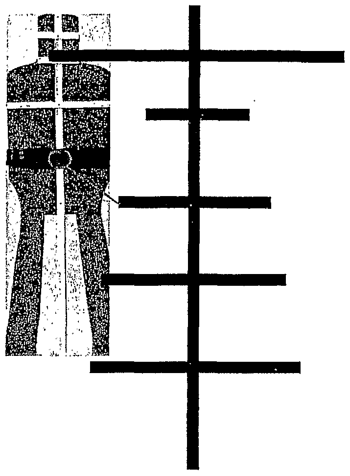
[0033] Figure 12 illustrates the reticle depicted in the form of a decal for taping upon the objective extremity of the scope or some other handy location. The left-hand Grid Line column serves as a reminder to denote the actual number of lines with which to divide into the animal's or target's outline for height measurement.
When determining distance to target, the upper right column, Aiming Point at level angle, denotes bullet impact point for a "6 Factor" gun zeroed or sighted-in at 200 yards. Using the grid-line center point, at 100 yards the bullet impact will be 1.84 inches (about 2 inches) high, and at 200 yards the impact point will be on target (zeroed) -- 200 yards is a typical "zeroing" range for such a gun and load. At 300 through 600 yards the lower indicia (crosshairs) provide a precise aiming point at each respective stated distance (progressively, 300, 400, 500 and 600 yards) to give the desired impact point. The upper center column, Aiming Point Grid Line at 45 degree Angle, denotes the angle correction when shooting uphill or downhill. For a "6 Factor" gun, simply move up the equivalent of one crosshair (about 2" of angle subtention) for a 45° angle shot.
[0034] Figure 12 illustrates the fundamental reason that this system works: Sections of significantly different trajectories forced into relative correspondence through the simple expedient of rotation and horizontal scaling.
[0035] FIGURE 12 (Rotation and horizontal scaling yields similar sections for all trajectory curves).
[0036] FIGURES 12-26 provide additional description of the present invention.
DESCRIPTION OF PREFERRED EMBODIMENT (for the purposes of clarification only)
[0037] Referring to Figures 1-3, a telescopic sight 10, embodying this invention is shown attached by a suitable mount 35 to a gun 12. The sight 10 is formed by a tubular housing 11 containing a forwardly positioned objective lens element 13, a rearwardly positioned ocular or eyepiece lens element 14, an intervening erector lens element 15, and a reticle 16 disposed between the objective lens element 13 and the erector lens element 15. In the case of vari-focal or zoom scopes, a positionally adjustable magnifying lens 17 is associated with the erector lens element 15. The exterior of the housing 11 may be equipped with rotationally moveable features 36 for adjusting focus, parallax, magnification ratio, windage and elevation. Each of the various lens elements may be single lenses or combinations of lenses, either aligned in proximity or glued together or a combination of these compositions. [0038] The reticle 16 is a circular, planar or flat transparent panel or disk mounted within the housing 11 in perpendicular relationship to the optical axis or line-of-sight 18 through the scope, and is positioned between the objective lens element 13 and the erector lens element 15, typically at a site considered to be a front focal plane of the optical system within the housing. The reticle 16 contains fine etched lines or hairline indicia comprising a center vertical hairline 19 and a center horizontal hairline 20, which orthogonally or perpendicularly intersect at a center point 26. The reticle further defines first, second, third and fourth horizontal range and aiming marker hairlines 21, 22, 23 and 24 (or other designs as may be appropriate to specific applications) respectively intersecting the vertical hairline below the center point 26 and vertically spaced apart and of sequentially increasing length. Each such range and aiming marker hairline 21, 22, 23, and 24 is bisected by the center vertical hairline 19, in the present design in a horizontal manner but potentially in an angled manner as necessary to account to the vertical component of wind drift, etc.).
[0039] We must also note that it is feasible to present a virtual reticle into the sighting system by other means, chiefly electronically, and that the absence of a physical reticle in no way alters the functionality of the present invention; therefore,
any means of generating aiming points that achieves the same goal as that described herein is fundamentally identical in nature and is also claimed.
[0040] Each combination of a gun and bullet or cartridge must be initially sighted in at 200 yards, or other selected basic zero range, which depends critically upon the ballistic characteristics of the specific bullet (refer to figure 12). The center point 26 then represents the basic sighted-in bullet impact point. The points of intersection of said first, second, third and fourth range marker lines 21, 22, 23, and
24 with said vertical hairline, designated first, second, third and fourth alternative aiming points 30, 31, 32 and 33, respectively, represent sighted-in bullet impact points at distances that are a function of bullet trajectory for the specific load used. For example, for a bullet and gun determined to be a "6 factor" system, as will be explained, the aiming points are for distances of 300, 400, 500 and 600 yards, respectively.
[0041] A "6-factor" gun and bullet combination is a system that produces a 6 inch drop from a "sight-in" impact zero point at 200 yards to the bullet impact point when the same combination of gun, bullet and scope adjustment settings is fired at 300 yards, using the center point 26 as the aiming point. Bullets of different characteristics and velocity (different gun and bullet combinations) will produce different "factors." Thus the aiming points 30, 31, 32 and 33 will correspond to different distances or ranges, which the shooter, knowing the characteristics of the bullet, will take into consideration when aiming and firing.
[0042] The aiming points 30, 31, 32 and 33 are useful because the trajectory curves of different bullets are similar, even though the bullets travel different distances - some similar-length section of each curve, whether closer to the gun or further from the gun, will have a sufficiently similar shape to allow accurate use of this system (refer to Figure 12).
[0043] The radially outer or distal portions of the center vertical hairline 19 and center horizontal hairline 20 are widened to form relatively wider or heavy posts
25 whose radially directed innermost extremities 28 are disposed on a circular locus about the center point 26. However, this is not a design limitation of this system, the main horizontal and vertical crosshairs can be of any particular design, as might be
necessary to provide the best performance in any particular application and could even be partially or folly absent as when only a central dot is used.
[0044] The various dimensions and spacings of the indicia on the reticle 16 are conveniently expressed as inches of subtention or angle at 100 yards, rather than the actual engraved dimensions on the reticle lens itself. Accordingly, the width of each of the posts 25 is 5.5 inches of subtention, and the width of the hairline portions of the center vertical and center horizontal hairlines 19 and 20, respectively, is 0.6 inches of subtention. The distance between the center point 26 and the innermost extremities 28 of the posts 25, that is the length of the center vertical and horizontal hairlines 19, 20, respectively, is 25 inches of subtention. However, it must be noted that these specific dimensions and ratios of dimensions are not the only possible useful designs. The important issue is usefulness in the specific application.
[0045] The distances or width of the separation between the horizontal hairline 20 and the first, second, third and fourth range lines 21, 22, 23, and 24 below the center point 26 are 2.0, 4.8, 7.5 and 10.5 inches of subtention, respectively - but other designs are feasible for other applications. Typically four, marker lines are typically of equal 0.3 inch width of subtention and are typically straight and orthogonally or perpendicularly bisected by the lower half or lower portion of the center vertical hairline 19; however, other line thicknesses and non-orthogonal intersections with the vertical line are feasible and may be preferable in some applications. When four such lines are used, the lengths of the first, second, third and fourth range marker lines are 4.12, 5.90, 8.32 and 9.72 inches of subtention, respectively; however, other lengths are feasible and may be preferable in some applications - the lengths specified above correspond to required corrections for a 10 mile per hour true crosswind component, which is a wind speed to which many experienced shooters can recognize and relate.
[0046] The foregoing dimensions are empirically derived and are critical to the accuracy and ease of use of this system in the standard application (such as a hunting rifle) - these datum are fundamental to the concept. However, one can also envision more complex systems that might be used for other applications wherein the extended range elevation aiming lines might be thinner, longer and include enlarged "dots" at specific intervals to indicate corrections for various true crosswind velocities
such as 5, 10, 15 and 20 miles per hour, etc. Moreover, for other applications, this basic concept could be extended to include designs having more than four range marker bars. No such application and embodiment should be considered to fall outside the basic tenants of this concept and therefore, this application is not limited to the specific design described herein; rather, this concept should be understood to cover any application wherein the spacings and lengths of the range lines incorporate the required characteristics so as to correspond to the parabolic nature of a projectile trajectory at any specific incremental (or other useful) range interval and wind condition. The central point of this art is that it uniquely recognizes the parabolic drop and crosswind deflections characteristics of real projectiles.
[0047] As noted elsewhere, in the particular embodiment described herein, the "factor" for a particular gun and bullet combination is determined by sighting it in at 200 yards using the center point of the reticle. Using the same 200 yard sight center point, a group of shots is then fired at 300 yards and average drop (in inches) is measured. This figure becomes the "factor" that is used to compute vertical bullet drop, wind drift deflection, both horizontally and vertically, and gravity correction for both uphill and downhill angle correction for that particular gun and loading.
[0048] Bullet drop is progressively curvilinear (following a parabolic curve), and is well predictable out to about 0.72 seconds of free flight (450 yards for a .308 Winchester; 500 yards for a 30/06; 600 yards for a 7 mm Remington Magnum; and 700 yards for a 30/378; all when used with high energy maneuverability bullets — traditionally known as bullets having a streamlined shape and a relatively high ballistic coefficient). Bullet drop for a 6-factor gun and bullet combination for example, results in a 6-inch drop at 300 yards. This factor is tripled to predict 400- yard bullet drop. This 400-yard drop is doubled to predict 500 yard drop. For 600- yard drop, the 500 yard drop is doubled and ten (inches) is subtracted from that result. This corresponds to a formula used to determine the spacing of these indicia.
[0049] For instance, a 6-factor bullet (150 grain 7 mm. Remington Magnum fired at 3,200 fps) computes thusly: a. 300 yard drop: 6" b. 400 yard drop: 3 x 6 = 18" c. 500 yard drop: 18 x 2 = 36"
d. 600 yard drop: 36 x 2 = 72 - 10 = 62"
[0050] In other words, for a 6-factor gun and bullet that is zeroed at 200 yards, the bullet drops 6" @ 300 yards, 18" @ 400 yards, 36" @ 500 yards, and 62" @ 600 yards. Other specific formula and extensions to longer times of flight are feasible so long as those describe useful characteristics of real projectiles.
[0051] A reticle embodying the present invention having the above characteristics and dimensions, will produce sufficiently accurate shots when using the respective reticle aiming points at the determined distances. For gun and bullet combinations that have a factor other than six, center impact distances corresponding to the various aiming points must be calculated accordingly. See Table I.
[0052] It is a useful fact that variable magnification scopes (commonly referred to as variable power scopes) with the reticle positioned in the first focal plane (in this design, adjusting the power setting of the scope also adjusts the absolute apparent spacing between the range indica) can be used to automatically adjust the described reticle, as required to provide to correct holdover for practically any "factor" gun and load by the simple expedient of adjusting the power setting to the required value, so as to generate the correct spacing of the indicia. In some applications, it might be necessary to alter the basic zero range and range increment but such correspondence will always be feasible. [0053] Use of a scope utilizing this invention for measuring target distance may best be visualized by referring to the grid line charts as shown in Figures 4A, 4B and 4C. Each grid line chart consists of a series of numbered horizontal straight lines sequentially spaced an inch apart (inch of subtention at 100 yards or approximately one minute of angle) and assumed to be visibly distinct in the scope at the indicated ranges. A target such as a 9-inch tall prairie dog is drawn to occupy the top nine lines of a chart, as shown in Figure 4A, and assumed to be placed at a range of 100 yards. The scope is then sighted onto said 100 yard target, producing the view shown in Figure 4B wherein the top of the prairie dog is placed at the center point 26, and the bottom of the prairie dog falls between the third and fourth range marker lines, namely between 7.5 and 10.5 inches of subtention from the center point 26. By interpolation, the bottom of the target, having an actual height of 9 inches, is 9 inches
of subtention from the center point 26. It is accordingly ascertained that the 9-inch high prairie dog target is located at a shooting range of 100 yards.
[0054] It should be noted that the target heights subtended by the horizontal range marker lines increase in direct arithmetic proportion to the distance of the target from the gun. Therefore, at 200 yards, the first, second, third and fourth range marker lines measure targets of 4, 10, 15 and 21 inch actual heights (rounded), respectively. At 300 yards, the first, second, third and fourth range marker lines measure targets of 6, 15, 22.5 and 31.5 inch actual heights (rounded) respectively. At 400 yards, the first, second, third and fourth range marker lines measure targets of 8, 20, 30 and 42 inch actual heights (rounded) respectively.
[0055] When the same 9-inch prairie dog target is viewed for example at 300 yards, the view through the scope is as shown in Figure 4C, wherein the target appears much smaller because of the distance at which it is located, and the range marker lines now correspond to progressive actual heights of 6, 15, 22.5 and 31.5 inches respectively in descending order down said center vertical hairline. Now, with the top of the head of the target at the center point, the bottom of the target will be located between the first and second range marker lines. This position corresponds to 3 inches actual height at 100 yards or 9 inches actual height at 300 yards. It follows, that knowing the actual height of the target, one can easily determine target range. In other words, in order to determine distance to target, target height is divided by inch reading on reticle. In the example of Fig. 4C, the 9 inch target would measure 3 inches on the reticle; accordingly, target range is 9÷3=3 (x 100), or 300 yards.
[0056] Once the shooter has determined target range, and when the shooter knows the factor of the gun and bullet being used, the scope can be accurately aimed by centering the appropriate indicia along the vertical hairline upon the desired location of bullet impact. For example, with a "6-factor" gun and bullet combination, and having ascertained that the target is located at 300 yards, and knowing that the main reticle center point 26 is for a 200 yard range, the next lower aiming point, consisting of the point of intersection 30 of the vertical crosshair 19 with the first range marker 21, corresponding to 300 yards, is, under ideal conditions and with a stationary target, used as the aiming point for a direct hit.
[0057] Use of this reticle with respect to a Rocky Mountain Elk having an estimated 25 inch chest height is illustrated in Fig. 5. It is seen that the 25 inch chest is spanned by about 5 inches of subtention of reticle distance. Accordingly, the range is 25÷5=5 (x 100), or 500 yards, and aiming point 32 is employed for shooting, centered upon target, again this assumes a "6-factor" gun and bullet combination, ideal conditions and a stationary target.
[0058] Compensation must be made for bullet deflection due to wind drift. To this end, the gun must be pointed into the wind. This is accomplished by moving the reticle aiming point in the opposite direction an appropriate amount. For this purpose, the applicable "factor" becomes the 10 mph wind correction or drift, applied in a linear manner. a. at 300 yards the drift is 6"; b. at 400 yards the drift is 6+6=12"; c. at 500 yards the drift is 12+6=18"; d. at 600 yards the drift is 18+6=24".
[0059] For a 5 mph wind, the drift values would be one-half the lOmph values, and a 20 mph wind would require twice the lOmph values and similarly for other true crosswind velocities.
[0060] The sight picture for shooting at a 9-inch high prairie dog at 100 yards is illustrated in Fig. 6A. The sight picture for shooting at a 9-inch high prairie dog at 600 yards with a 10 mph left crosswind is illustrated in Fig. 6B. The view through the scope when shooting at a target at 500 yards is illustrated in Fig. 7. Figs. 8 and 9 illustrate adjusted aiming points to compensate for 10 mph and 20 mph right-to-left crosswinds, respectively. For this purpose, the ends of the range marker lines, having the above lengths, constitute aiming points to compensate for 10 mph winds at the respective ranges. Length of the range marker bars on each side of the vertical centerline are one half the total length or 2.06, 2.95, 4.16 and 4.86 inches of subtention at 100 yards respectively.
[0061] Compensation must also be made for the effect on the path of the bullet of the spinning thereof. The rifleman's idiom designates this as a "Magnus effect." It may also be referred to as "Yaw of Repose." these are the vertical and
horizontal elements of deflection in a crosswind when considering a gyroscopically spinning projectile or missile.
[0062] The formula for compensating for the potential worst case effect of
Magnus is to adjust l/4th the total value by sliding that point onto the target. In the illustration of Fig. 10, there is shown the aiming point as an interpolated point left one equal wind bar (10 mph) and 1/4 above the left tip of the third range marker line.
(Unusually low-drag high-speed bullets may react to Magnus only a small percentage of the adjustment in Fig. 10; however, hunting bullets do not fall into this category.)
The rule is to construct a "kill zone" on the target and then hold "worst and best" Magnus movement so that the bullet is aimed with sufficient accuracy to intersect the kill zone.
[0063] Computing simultaneous Magnus and Yaw of Repose values and crosswind values:
1. With conventional (right-hand) twist barrels, these effect make the bullet rise with a right-to-left crosswind, drop with a left-to-right crosswind.
2. Add l/4th the horizontal value vertically to the final aiming point using the reticle wind bar as a transparency overlay.
[0064] As noted previously, it is also possible to incorporate automatic vertical-component crosswind correction into the range markers by aligning those at a slight angle to the horizontal so that the sighting correction for a crosswind automatically incorporates the required correction for the vertical component of wind drift. While not embodied in the accompanying sketches, this method is claimed and recognized as a logical extension and improvement on the basic concept of this reticle design. It is recognized that this method would require separate scopes for guns with reverse rifling twist directions and for guns used in the southern hemisphere and might require special angles for guns used at certain locations. However, for the vast majority of hunting gun applications, one basic correction angle would suffice to provide sufficient accuracy of correction as to achieve the required shot placement accuracy. [0065] When shooting uphill or downhill, bullet impact point will be higher than when shooting level at the same total target distance. In other words, when computing uphill or downhill gravity values, it must be noted that angle shots require
less hold-over, that is the aiming point is moved upwardly on the reticle, because of a lesser gravity pull although bullet drag remains the same. A sight picture and aiming point for a "6-factor" gun and bullet at a 45° up-hill shot at 500 yards slant range is illustrated in Fig. 11. The appropriate sighting adjustment in such situation is to move up one range marker line for a 45 degree angle, twice that or two range marker lines for a 60 degree angle, and one half that or up one-half the distance between appropriate range marker lines for a 30 degree angle.
[0066] The formula or adjustment for a 60° angle shot, for example, is as follows: a. at 200 yards, raise the aiming point an amount equal to 2/3rds of the factor, or 4"; b. at 300 yards, double the 200-yard value, or 8"; c. at 400 yards, double the 300-yard value, or 16"; d. at 500 yards; double the 400-yard value, or 32". [0067] The reticle of the present invention performs with each gun and bullet with the same precise degree of accuracy. The shooter is thus provided a similar but unique reticle decal for each combination. It must be stressed that the associated decals are an integral part of this system and as such, the concept of application specific decals is also part of this art. [0068] While a single reticle constructed as described above may be used for most gun and bullet combinations, specialized reticles may be needed for certain particular gun and bullet or cartridge combinations, scope magnifications and unusual applications. Therefore, the ratios of indicia spacings and lengths are not unique and other ratios of and lengths can have value for specific applications, so long as these correspond to range-finding functions, etc., as describing a parabolic trajectory, the design will be an obvious derivative of this basic concept. This is a parametric design issue and the critical factor of interest is that specific ratios of spacings and lengths are required to produce useful results.
[0069] It is further to be stressed that with this design the shooter need not divert attention from the image in the scope for first determining distance and other corrections and second for finding the proper aiming point.
[0070] A telescopic gunsight utilizing this invention is particularly well suited for shooting at moving targets. It is generally known that a deer starts running at about 12.5 mph. The distance between the reticle center point 26 and the innermost extremities 28 of the posts 25 compensates for a target moving at 12.5 mph. Further adjustments can be readily made for targets moving at other estimated speeds and angles, in direct proportion to the 12.5 mph speed adjustment.
[0071] The final sight picture provided by the reticle embodying the present invention, corrected for range, wind, external ballistics, and target movement results in a straight line aim and shot at the target in the same manner as a point blank range shot. This enables the shooter to have much more confidence in the result and therefore to more easily achieve accurate shot placement.
[0072] Using a reticle of the present invention, observing the target conditions, and applying the foregoing simple mental calculations, an aiming point on the reticle is selected and centered on the desired target impact point. This can be done quickly with less stress or doubt, when compared to other systems. The shooter can then concentrate on firing the gun in a relaxed mode with a minimum of movement or "jerk" of the gun and then "look the bullet into" the target — this is otherwise called "follow through" and has long been recognized as critical to marksmanship. [0073] While particular examples of the present invention have been shown and described, it is apparent that changes and modifications may be made therein without departing from the invention in its broadest aspects. The aim of the appended claims, therefore is to cover all such changes and modifications as fall within the true spirit and scope of this invention. [0074] A final point of significant value revolves around the difference between first and second focal plane reticle placement in a variable power scope. The former design provides for a means of making any "factor" reticle design fit any "factor" application. The disadvantage of this method is that it requires use of the variable power scope only at one specific power setting for the particular application. The disadvantage of the latter method is that it requires use of a specific "factor" reticle. Each system has advantages and this art covers any and all such applications.
THE ADINO AIMING SYSTEM
The Adino is the 2nd focal plane system based upon the TDS TRI-FACTOR (PATENTED).
The Adino uses the first part of the Tri-Factor system as we use the original factor to establish the first zero.
Step 1. Zero according to the factor program using the fastest cartridge available for your rifle.
Step 2. Load the next heaviest bullet. Firi ng a sighter shot at RMB #3 will result in the bullet hitting low (top target- bottom left bullet hole)..
Step 3. Hold the Crosshair of Baseline on a known geographic point - such as the horizontal timber in upper target - now turn the power ring down until the Aiming Point of the reticle overlaps or superimposes the bullet hole.
Step 4. Firing the next shot at the # 4 RMB target, should you have accurately lower ed the RMB marker, you will have an impact point similar to the bottom target where the bullet hit slightly right but level. In this case, this was a 600 yard target, firing a .308 168 grain match bullet.
The low left impact bullet hole was the result of a slight right wind and an undercorrected power advustment.
A TWO HUNDRED YARD - OR LESS - GUNFIGHT .
In this case the fight will be settled in less than two seconds after the first shooter enters the Psychophysiological Performance State for a Gunfight which activates his Action Phase. Our shooter will win if he can (1.) measure the distance, (2) react with a correct Gun Solution and (3) fire in less than one second. Bracketting - the head, dropping the bar over the head to the hostile's nose - while dropping the sear - wins evedry time.
A THREE HUNDRED YARD - OR LESS - GUNFIGHT
A three hundred yard fight is the average longest shot for Vietnam ere snipers, the distance Carlos Hathcock killed the Cobra, the distance Zaitzev killed Thorvald and the range the A.T.F. snipers fired in support (?) of the fight at Mount Carmel. This seems to be the break point for otherwise good shots to get themselves killed in battle. Why? It looks easy and is a dead cinch at a KD range shooting in the psychopsysiological condition known as Yellow. What happens at 300? For one thing the ration of wobble area to kill zone - 1 to 3 -Js a bit harder to get just right. We miss more in Black. 300 yards in combat is not that easy. This is why we bracket the shot once more. Our shooter has only two things to work on - the same two that always work in practice. Bracket and fire.
CAUTION THE ADINO REQUIRES ONE FINAL STEP. MEASURE AT FULL POWER. THEN CHANGE THE POWER SETTING TO YOUR BULLET'S ENERGY MANEUVERABILITY RATING JUST PRIOR TO FIRING.
AFOUR HUNDREDYARDSHOT:
A four hundred yard shot involves all the variables of distance, wind and angle. The TDS TRI- FACTOR System converts these hitherto "Art" items a science. Measurement uses the full top-of-head-to- belt region for two reasons;
A. Choosing a smaller y axis results in an inaccurate measurement. As the angle of departure . increases the y axis increases commensurately. The TDS TRI- FACTOR System allows the shooter to get the jump on an opponent at the 400 yard range as we still retain an accurate bracket capability. Measurement is as fast as the eye can drop from the top of the Hostile's head to his - or her - belt. (Anyone know? Is Jane going to Iraq?)
B. Bullet v. side wind past 300 yards = wind wins. Yaw of repose - the vertical component shift of a bullet in a sidewind exceeding 10 mph as it approaches transonic flight requires a correction. Simply add a 45 degree vector - "up" in a Right crosswind, "down" in a left crosswind - to the tip of the wind bar referencing the 10 mph Wind Bar. The tip of this vector adjusts for both Magnus side-to side and Yaw of Repose up-and-down side-wind bullet deviation. ILLUSTRATION PAGE 7. CAUTION: THE ADINO REQUIRES ONE FINAL STEP. MEASURE AT FULL POWER. THEN CHANGE THE POWER SETTING TO YOUR BULLET'S ENERGY MANEUVERABILITY RATING JUST PRIOR TO FIRING.
The Yaw of Repose Solution.
The idiosyncraticness of Yaw of Repose is the reason it is so misunderstood.
An especially obtuse argument against adjusting for this vertical bullet movement was postulated by someone who should have known better. This gentleman's school solution was a .550 BC bullet travelling 3,300 fits as it passes 100 yards flight. He clinched his argument with the statement "The 10 mph full value right wind created a Yaw of Repose effect of only 0.2 of an inch lift." At that point I would agree. I feel that any condition which creates a distracting bullet movement of less than 30% of the bullet's Circular Error of Probability puts me to sleep.
He missed the point. A .300 Winchester Magnum 165 grain bullet from muzzle to 200 yards is pretty much its own master.
Beyond that point the wind whips it down and at 300 yards the bullet Magnuses as the wind sees fit. At 500 and beyond as it enters transonic flight it yaw of reposes vertically. It even shifts its angle of attack, pointing upward in a right and downward in a left crosswind. A full value laminar wind will create a 17 degree vertical correction. Most cross- winds in excess of 10 mph shift the angl;e of atack to more like 7 degrees. Do we have time for this in combat? No. We need a simple correction commensurate with the exigency of the moment. The TDS TRI-FACTOR System ignores Yaw of Repose as long as its effect is negligible - in Baseline, Bl and B2, when close proximity makes saving every quarter second response time essential to life. At 500 and 600 yards, where an adjustment is necessary to keep the bullet in the kill zone, we have that extra quarter of a second to insure a first shot kill. Combat is a world of its own, Fig. 1, a photo I took of the Ho Chi Minh trail exiting North Vietnam, illustrates what close proximity does to a well honed trigger finger. Those bomb craters were
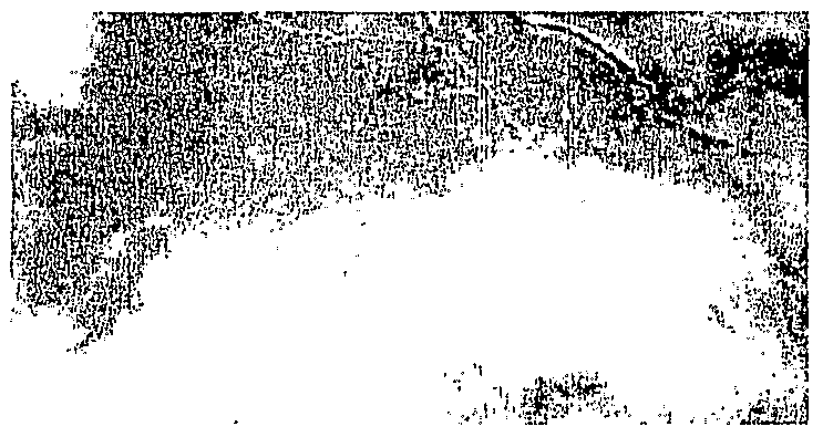
made by Top Gun dive bomber pilots who routinely placed their bombs in a thirty foot circle - back home - without the distraction of a thousand AAA batteries opening up as we cleared the clouds. Figure 2 is paying attention to business, which means when you are working up close don't clutter up your mind with non essentials.
Yaw of Repose will move the bullet vertically - in B3 and B4 - l/4th the horizontal component. This is not a non-essential. But you have time for it at that distance.
THE T.D. SMITH TRI FACTOR
INTRODUCTION: Some time ago, I was hunting in New Mexico with an outfitter who also happened to be a very good friend . We were examining a very good antelope. He told me he couldn't give me a good range evaluation so he recommended I pass the shot. While he was attempting to judge the distance I had been measuring it. Placing the thick post on the bucks shoulder I let off easy on the trigger and made a one shot kill.
He asked me what I did and I told him it was a system. I used to train fighter pilots. I set my pipper at 6 minutes of angle, the buck was two thirds the pipper, the addition came out to five fingers, there was no wind so I put the tip of the spearhead on his shoulder and the bullet took out the top of the buck's heart.
His answer, "what the hell are you talking about?," Made me realize that I needed to get this in print. In a much less confusing manner than I had explained to my friend.
By 1964, 1 had already been shooting targets for three years and very much desired getting back to tightens and try that big gunnery range in Vietnam. I already had my record in Centerfire Pistol, the communist countries had just recently managed to get the course deleted from the Olympic agenda so I didn't feel there was any reason to hang around and I wanted to get back in airplanes. My boss told me he would approve my transfer but first I had to shoot the International Championships at Fort Benning, Georgia, which would also select the Olympic team by choosing the gold and silver national winners for the team. There were two pistol events left for Olympic participation, the Free Pistol and Rapid Fire Pistol, but not the Centerfire Pistol where the U.S. had two team and an individual gold plus an individual silver locked up between Bill Blankenship and myself. The Centerfire Pistol was now considered a military weapon - since Bill and I had both exceeded the Russian record holder's score by six and four points respectively. Politics sucks.
I borrowed a free pistol and shot the course the week after winning the Georgia State pistol championship which was scheduled as a warmup for the national championships in Fort Benning. I made the Free Pistol Team on the third day, which left 2V2 weeks to kill. I bootlegged a parachute school and then found out about the sniper school where I was allowed to sit in by an old Army friend.
The Rangers use a scope that costs around $6,000.00 and sets up everything for the shooter. When the proper inputs are made, the shooter simply places the crosshair on a moving target and pulls the trigger. Everything is computed. This Tn Factor school is an independent hunter's adaptation that accomplishes the same thing with a $350.00 scope. It requires- a-little thought - but not too much.
There were a lot of problems involved in adapting the principles of the sniper school, to a hunting program. I had to substitute a $350.00 hunter's rifle scope to do the job of the Ranger's much more programmed scope. There are a lot of differences in these two schools of thought. We insist upon a clean one shot kill and the sniper is happy with a hit. What we are trying to do is much more precise. We also don't shoot at a mile distance.
We depart the sniper school when we teach a commonalty of calibers because the sniper is concerned only with one caliber whose ballistic curve is set in the scope and the adjustments. The sniper plans a shot and cranks the' knobs. He places the cross hairs on the target. We use a corrected aim point.
Our course requires one precise shot. We don't have corrected fife by an observer. This "one shot kill" requires training which includes technical, tactical, physical, psychological, moral, intellectual and equipment preparation. Physical conditioning, intellectual capabilities designed to incorporate understanding of the various left brain and right brain functions, equipment, physical training to drill trained responses into long term memory, tactical hunting skill and individual psychological training are a minimμm program to insure a one shot kill under severe stress. This section will allow us to compute the shot. Without the other work, we might as well spit in the wind for all the good that knowledge will do us.
THE ONE SHOT KILL
This system.is designed to provide the hunter a simple procedure for measuring the distance to an animal; then to quickly compute an incorporated holdover point for bullet drop, lag point for wind drift, a lead point for animal movement, and hold down point for severe uphill or downhill angle correction. That sounds like a mouthful and it does involve a little study. Since I'm not very smart I have to use fingers and some small memory work but if it works for me it will work for anyone else who managed to get through Dick and Jane.
I've been asked "why bother?" The answer is that animals have been educated a bit since Karamojo Bell offed into the woods with his 7x57. Their comfort zone to a human was progressively increased in distance by the spear, the arrow, and the black powder rifle. Now the magnum claibers have increased it to the point where we frequently see a really good set of horns streak to 300 yards and then begin to slow down and make a check turn to see what bothered him. The Tn Factor is just the next step in attempting a one shot kill under increasingly adverse conditions.
To my limited knowledge this has not been attempted before because the ballistic tables are rather confusing if one enters them trying to find a common factor for all these problems. Especially so if one desires a common factor for a great variety of rifle calibers.
I think it succeeded but we first need to go back to the basics in order to understand it.
The bullet is the subject of this drill, not the rifle. The bullet begins to fall as soon as it leaves the muzzle of a rifle. The fired bullet begins to slow down as soon as it is fired. At first, the bullet travels fast, covering the first 100 yards quickest. Since we are considering 600 yards as our maximum range, the bullet travels the last distance between 450 and 600 yards the slowest. Gravity causes the rate of drop to increase as flight time increases. Since it takes the
bullet more time to travel as the speed slows, the effects of gravity and wind increase as the range increases. The Tri Factor's entering argument initiates at 300 yards because the anomaly of bullet drift is broken at 300 yards and this entry point allows all the other solutions to integrate at that distance.
The only way we can achieve a commonality for all the different kinds, shapes and speeds of various bullet travel is to begin at 300 yards and then work forward and back to solve these problems in a simple manner. And it is simple.
BULLET DROP. The bullet is affected by gravity just like any other falling object. Hold a bullet in your left hand, hold the rifle horizontally in your right hand, fire the rifle and drop the bullet at the same time and each bullet will hit the ground at the same time. Even though the bullet is traveling fast, once it has been fired by the rifle, it falls to the ground in normal time.
BALLISTICS. This is the science dealing with the motion and flight characteristics of projectiles. The study of ballistics in rifles is divided into three categories; internal, external and terminal.
INTERNAL BALLISTICS concerns what happens to the bullet before it leaves the muzzle of the rifle. Internal ballistics factors such as projectile length, weight, and configuration require different twists in the barrels, lands and grooves to stabilize a bullet in flight. The lands rotate the bullet and give it a twist. This spin stabilizes the bullet and gives it accuracy. The powder burning speed and type, weight of the charge, alignment and spring of the primer and primer type, squareness and concentricity of the brass case and neck wall, together with bullet shape and seating depth which determines bullet jump all contribute to internal ballistics and vitally affect accuracy. The concentricity of the barrel and the amount it whips or vibrates during this cumulative firing sequence vitally affects accuracy. How much the action bends and whether it allows the bullet a straight and uniform entry into the lands is vital to accuracy. For consistent Olympic grade accuracy - and long range hunting accuracy - the barrel must be free floated so it's vibration is not affected by contact with the stock. Bullet speed should be controlled for consistency of effect to a variation of about 15 fps. One side effect is that slower bullets fall lower in the group and faster bullets go higher. Also, bullets don't travel a laser beam; they cloverleaf to the target. It is better if they all arrive at the same point of the pattern so you can better set your group for a precise sight in.
EXTERNAL BALLISTICS deals with factors affecting the flight path of the bullet between the muzzle of the rifle and the target. External ballistics factors. When the bullet is launched into the earth's atmosphere its path is influenced by various forces and elements.
TERMINAL BALLISTICS deals with what happens to the bullet when it comes in contact with the target. Terminal ballistics concern bullet penetration and depend on the range, velocity, bullet characteristics, and target material. Rabbit or Rhino? Greater penetration does not always occur at close range with the high speed bullets because they tend to disintegrate. I personally love them because they are so accurate, but Sierra hunting bullets -just like the original Sidewinder missile - specifically require a spin and heat time before they become good killers. This is the manufacturing process which makes them accurate. Some of them require a 125 yard run to spin up to cohesive form. Another nit noi is that the exposed lead tips on bullets burn off and create an aerodynamic which is generally insignificant. Bent bullet tip deformity is another subject. The bullet trade off is for destruction rather than some insignificant increase in accuracy.
TEMPERATURE: As the temperature rises, the bullet hits higher on the target. A 120 degree change in temperature will move a .300 magnum 180 grain boat tail bullet about an inch high at 300 yards.
ATMOSPHERIC PRESSURE: As the atmospheric pressure rises, the bullet hits lower, in other words, the higher the humidity is the thicker the air is and the bullet works harder and is slowed down by the thicker air and it strikes lower.
WIND: A strong wind from the rear causes the bullet to hit high while a strong head wind causes the bullet to hit low.
UPHILL OR DOWNHILL: Firing uphill or downhill causes the bullet to hit high.
CHANGING LIGHT: Changing light conditions can affect the way your rods and cones in the back of your eye "see" the target and cause the bullet to hit in different locations.
EFFECTS OF ALTITUDE ON BULLET DROP: At altitude, both air density and temperature drop, and air drag on the bullet decreases. At 10,000 feet and 300 yards, the 30/30 flat nose bullet shoots almost 9 inches higher. I cite this for example only. Your 8 factor πfies however, have a negligible effect at altitude.
Sight in a 7 mm Remington Magnum with 175 grain spitzer bullet at sea level and the drop difference at
10,000 feet will be only 3.91 inches at 500 yards. This is for zero degree slant range. A high speed 7 mag bullet will impact 6 inches high at 600 yards providing every thing else is constant - which it isn't. The temperature will probably be lower than that at the range where the load was sighted in. This results in a 2 foot per second decrease in velocity with each degree of temperature change. This probably zeros out the altitude effect.
EFFECT OF UPHILL/DOWNHILL SHOOTING: There is another subject that routinely arises in mountain hunting and that is "If I am shooting uphill, what happens to the bullet and what do I do to compensate?" The first thing to remember is that you will hit higher either up or downhill because the bullet is less effected by gravity. So you have to compensate the other direction, down.
These factors combined with slight differences in bullet shape and weight, powder charge, chamber size and pressure, muzzle velocity and barrel erosion all influence the flight of the bullet. For this reason you rarely see bullets enter the same hole.
MINUTE OF ANGLE (moa): It is the standard unit of measurement used in adjusting rifle sights and other ballistic related measurements. It is also used to indicate the accuracy of a rifle.
INCREASE OF SHOT SIZE GROUP. Just as the distance covered by a minute of angle increases each time the range increases, a shot group can be expected to do the same. A 3 inch group at 100 yards will be spread 9 inches at 300 yards.
CROSS WIND DRIFT: Unless it is severe, wind is a negligible factor out to 300 yards. The most serious effect is our ability to hold the rifle steady enough for a long range shot. Twenty mile per hour gusts during the firing sequence are more detrimental than a 12 inch drift correction. Unless you have an exceptionally strong muzzle wind which would affect the gyroscopic tilt of the bullet, the actual bullet path will not parallel the wind drift path during the first 300 yards to the target. Because of its powerful initial inertia, the bullet does not follow the crosswind precisely during this first 300 yards of travel. The crosswind bullet motion is accelerated relatively slowly, and in fact the crosswind component of the bullet's velocity never does grow to equal the crosswind velocity - but it is very close to linear from 300 yards on.
EXTRANEOUS AND INSIGNIFICANT STUFF: It's unfortunate but seemingly intelligent gun writers confuse the living hell out of people by complicating the system with extraneous details that actually have a small influence on the bullet's work in the real world. And are seemingly inserted simply to impress the reader with the writer. It is hard enough to remember the necessary part. Memory time should be spent only on mastering the most significant factors such as the effects of gravity and other external factors during flight time.
This is a good time to examine the affects that produce an effect on the bullet.
CORLIOISACCELERATION: (from thebookMODERNPRACTICALBALLISTICS.) Due to the earth's rotation, projectile paths drift a slight amount (to the right in the northern hemisphere; to the left in the souther hemisphere) over the earth. To visualize this phenomenon, on a merry-go-round rotating counterclockwise, an object thrown between two people will appear to drift or curve to the right. If viewed from the ground, the path does not curve, of course. Due to the earth's rotation, this Coriolis acceleration is Y = 2w * V * sin (lat) where w is earth rotation rate (0.0000729 degrees per second), V is average projectile horizontal speed, and lat is latitude. For V = 2800 fps at latitude 45 degrees north, Coriolis is 0.30 fps/s, which is less than 0.01 of that due to gravity. Drift at 100 yards is 0.02 inch to the right, and at approximately 700 yards, is 1 inch to the right. At latitude 45 degrees south, the drift would be the same amount but to the left.
Since this extremely small effect is constant and repeatable, it is negligible for most purposes. In naval gun battles at ranges of several miles, however, this effect can be (and has been) significant if not properly accounted for. The F- 16 fighter weapons computer has no correction for cannon fire as the time of flight is negligible, but.it installs a 6 inch correction for 5,000 foot dive bombing with either a Mark 82 or Mark 84 bomb. A 15,000 foot dive bomb carries an 18 inch correction.
An easy system to use for rifle bullet correction is to take the time of flight and correct one inch for each second of free air time.
GYROSCOPIC EFFECT: A spinning projectile from a rifled barrel is, in effect, a free gyroscope. When subjected to a twist or torque, it tends to rotate about an axis perpendicular to the axis about which the torque is exerted. The front wheel of a bicycle is a good illustration of this phenomenon. If the bicycle is tipped to the right when rolling forward, the front wheel resists tipping and instead its axle rotates to the right, turning the bicycle to the right.
While following its path, which is constantly curving downward, a projectile is subject to a force (air drag) on its nose from underneath, causing a twist or torque. If its spin is clockwise, this upward torque causes the projectile's nose to rotate and offset slightly to the right (like the bicycle wheel) as seen from the rear. This offset causes air drag to act unevenly and to push the projectile slightly to the right.
The effect of gyroscopic drift is difficult to analyze precisely because many variables are involved. Drift tables, which have been determined mainly from well-controlled army and navy tests, indicate that gyroscopic drift is roughly double that of Coriolis drift, and thus is also negligible for most purposes. It is interesting to note that with counterclockwise or left-twist barrel rifling, gyroscopic drift is to the left in the northern- hemisphere and more than cancels the effects of coriolis drift.
TRI FACTOR THEORY: This system of mine began at the 300 yard mark because that is the distance that the energy overlays begin to precisely overlap. Which overlap is the key to producing a simple memory factor that will solve all our field problems.
So we have discovered the TRI FACTOR SYSTEM. This factor will satisfy the requirement for simplicity in a stressed trophy hunting environment and will be used to add, multiply and divide. In order to compute both drift and drop, plus uphill and downhill angle corrections. The system will produce accurate hold corrections not just for your rifle but for all the rifle/bullet combinations normally considered to be long range rifles.
One last consideration. Most of us initially feel there are a lot of "smoke and.mirror" inputs to long range shooting. Since we are not really sure why, this uneasiness translates into a confused motor program in our shooting which is always detrimental. Understanding a simple system that you are confident with will eliminate this confusion and you will shoot better. I don't recommend 600 yard shots Mt in-very isolated instances. However, when I am confident that I can compute a 600 yard shot and then evaluate my chances for a one shot kill, it increases my. confidence in all my shooting. When I know what to do at 600 yards it makes for a very confident state of mind. I am deadly at 300 yards. And this confidence did not come until I was sure of my stuff at the longer yardage.
THE TRI FACTOR
STEP ONE: The object of this study is to enable a hunter to measure the distance to an animal by trigonometric triangulation.
STEP TWO: Computing the shot applies the specific factor idiosyncratic to that particular rifle/bullet combination. Reloading tables may seem to be anomalistic, but that is not always so. There is very much consistency in the energy curve of similar bullets. We will organize all long range bullets in three common projectile groups. The study is of the bullet, not the rifle. The rifle only enters into the discussion after the proper bullet is selected.
BULLET SELECTION: The first thing necessary is to determine the class of game you will hunt and the distance you expect to shoot. There is a minimum energy requirement most hunters accept for these. Although I have friends who take only brain shots and the guys in Alaska have recorded Grizzly Bear kills with a .22 rifle, in consideration for "one shot" kills, the following criteria seems reasonable.
Class: Species: Minimum "one shot kill" energy
Class 1 Javelina, Coes deer, antelope 1,400 lbs energy
Class 2 Deer, sheep, mountain goat 1,400 lbs energy
Class 3 Caribou, wild boar, black bear 1,800 lbs energy
Class 4 Elk, moose 2,800 lbs energy
Class 5 Grizzly Bear 3,500 lbs energy
The above mentioned energy requirement doesn't come from the muzzle energy column, it comes from the terminal ballistic point of entering the fur.
All bullets will not compute on this program. I never intended to include the 30/30 in this study. Choosing a factor to simplify computations for figuring drift and drop, that will apply to all our long range rifles, requires that the bullets meet the following criteria.
SECTIONAL DENSITY: The bullet must be of a minimum sectional density of .250. Sectional density is the ratio of the bullet's weight in pounds to the square of its diameter in inches. Think of it this way; bullets of the same shape but with more weight in relation to their diameter will retain their velocity and energy better.
BALLISTIC COEFFICIENT: It must have a minimum ballistic coefficient of .350. Mathematically, this is the ratio of a bullet's weight to the product of the square of its diameter and its form factor. If this is unfamiliar to you, get a handloading book and compare, for instance, the picture of a boat tail spire point bullet with a flat point bullet. The swept back nose and the angled tail section of the boat tail spire point bullet obviously allows it to push through the air with the least resistance. Thereby, it retains its speed longer because it doesn't have to fight so much air friction. The higher the number, the better the performance.
CARTRIDGE CASE SHAPE: The bullet has to be propelled at the - safe - high end of the chart. Ignore Rimmed straight, rimmed bottle neck or rimless straight cases. Rimless bottleneck, belted bottleneck, belted straight or rebated bottleneck cases safely loaded to the top end of their group will work very well. Since this is obviously a long range program we need a rifle that will consistently group three shots into a 1 inch or minute of angle (moa) group.
THE SHOOTER: We need to work on rifle rest shooting. The average hunter cannot hold a rifle, standing, and shoot a tighter group than a pie plate at 100 yards. Gary Anderson, the Olympic and world record holder in standing rifle shooting, came back to our room at the 1964 Olympic Games in Tokyo with a target I will never forget. He placed all ten shots in the 3" ten ring at 300 meters. But Gary tells me that was with a strapped in leather shooting coat and other gear designed to lock him in very tightly. He will not personally fire from a standing position when his game is .further out than 100 yards. I asked our other roommate, Lones Wigger, the other half of the world's greatest Olympic rifle shooters, what his standing position distance is. Wig told me he will not shoot from a standing position if he can get to a kneeling position.
We need to learn the feel of a precise long range shot. This requires serious practice on a bench rest and a good rest of some sort in the hunting field.
Just as much practice is necessary for the standing position as it is vital for a hunter. When a shot presents itself, we will ruin the shot if we first instinctively pause and look for a rest. The ability to shoot standing is just as important for a hunter - but only within the parameters for making a certain one shot kill. When the animal is jumped from his bed, transitioning from a walking to a standing shooting position is very proper and there is a very good- system for it. • . -
However, for long range shooting, we want a rest that will guarantee our hold for the heart size of the target. If the heart is 4 inches in diameter then my hold has to be 1 minute of angle and 400 yards is my limit with that animal.
THE RTFLE: We require an accurate rifle. Accuracy is relative to the intended target but for my purpose I'm defining accurate as one that will shoot 3 bullets into a one inch group at 100 yards. Also I am much more interested in what the rifle will do with the first bullet shot out of a clean cold barrel than I am with how it handles subsequent shots.
The last and most important factor is the trigger puller. We hunters have to develop a mental "comfort zone" and only shoot within it. You remember the day you outshot everyone? You couldn't miss. That is called "flow."
But you also remember the day you really didn't shoot well. The distance you shoot, or whether you try the shot at all, depends on a lot of things that make up your individual comfort zone and we know this confidence level varies with all of us.., seemingly on a daily basis. So this also becomes a criteria in deciding whether we execute a shot.
MEASURING DISTANCE
There are a number of excellent methods for measuring distance These include; measuring distance from a map, pacing the distance, estimating by eye, range cards, use of a mil scale reticle or mil scale in binoculars in conjunction with mil relation formula (useful only in a military context measuπng everything from a man to a tank.) See illustration 1, below
Illustration 1.
■ The one I use is a variation on the one I taught in fighter aircraft to determine effective firing range to anoLher airplane. The circle in the center of the gunsight is 2 mils in diameter and will precisely superimpose a 2 foot circle at 1,000 feet, and an eight foot circle at 4,000 feet. The Migs I was concerned with had eight foot tails. If the reticle ringed the tail I was at 4,000 feet and had to drive in closer until he was in firing range, when my reticle covered about a third of the migs tail, I was at "sighted in" range See illustration 2.
Illustration 2. Com ibbaatt fi fillmm o off a ann F F-- 110055 w wiinnggmmaann fi firirinngg o onn a a M Miigg 1177 a abboouutt t too f fiire on his leader. The Mig is in the lower right side of the reticle and the F-105 leader about to be shot down is in the upper right
Illustration 3. This shows the picture of a MIG at 4,000 feet and 1,333 feet. The pipper (small white circle in center of gunsight) is 2 mills across, which is two feet at 1,000 feet and 8 feet at 4,000 feet. When it πngs the tail the distance is 4,000'; if it is 1/3 rd the size of the tail the distance is 1,333 feet. You have measured him for a shot within range. The illustration is for distance: not aspect angle for an aerial shot.
The Tri Factor system is the same The purpose is to measure the distance to a target in order to guarantee a fatal hit. In our case it is an animal at an unknown distance It is based on the fact that if one side and two angles of a triangle are known, the other two sides and angle can be calculated by the methods of plane trigonometry. We will triangulate by placing our πfle scope at the triangle's trigonometric angle A Our triangle's X-axis base line or horizontal leg will extend to the base of the animal's chest and the animal's bπsket to shoulder silhouette will be the Y-axis or vertical side of the triangle If we know the size of the angle A in minutes of angle and the height of the animal's chest outline we can compute the distance to the animal
In the hunting field we use the known size of the animal's shoulder to brisket (top to bottom of his chest) silhouette measurement and divide that by the number of minutes of angle which you measure with your rifle scope. We use the reticle of the scope as a measuring device which we mentally interpolate by dividing it into minutes of angle. The Tn Factor system uses the lower thin wire in a duplex scope reticle (illustration 4) for this purpose. This wire is described as the .0012 stress relieved platinum wire (1/3 rd the width of a human hair) superimposed over the heavy portion of the lower reticle post, which we now call the post with the top of the post being the spearhead.
Because it is not named by the scope companies, We will hereafter call this lower 180 degree radial thin wire the "pipper." (Illustration 5, next page ) The pipper is the name of the firing reticle in the airplane. We've been firing "through the pipper' forever so I'll just transfer the term to the hunting field
The object of surveying is to determine accurately the measurement of distance; which is also our concern in hunting. All measurement for distance is made perpendicular to the direction of gravity (designated as horizontal). Two types of angular measure are used throughout the world, the sexagesϋmal and the centisimal:
Sexagesimal system Centesimal system
1 circle = 360 degrees 1 circle = 400 grads
1 degree = 60 minutes 1 grad = 100 minutes
1 minute = 60 seconds 1 minute = 100 seconds
We use the Sexagestimal system Of the four types of surveying measurements, we are interested in the first: horizontal distance With a surveyor's level, the difference in height between two points can be determined The surveyor sets up his transit horizontally and the graduations are read through the surveyor's pipper on a rod held vertically by his helper at a distance The surveyor reads the mark on the rod through his pipper and thereby deteπnines the distance separating him and the rod holder.
Illustration 4. The Tri Factor. Calibrate the reticle in minutes of angle, divide the animal's known chest measurement by the minutes of angle subtended (6 in this case) and you have the distance in yards.
Illustration 5. Both illustrations are of the normal duplex reticle . The "pipper" is pointed out on the right side illustration and consists of the thin low wire from the intersection of the horizontal wire to the top of the post. This post top is called the "spearhead" and it should be noted that it is difficult to see in poor light.
We now have three new words describing the reticle. There are no dictionary words descπbing these three pieces of the reticle so:
1. The "pipper is the low thin wire,
2. The "spearhead" is the point of the top of the post,
3. The bottom thick wire is the "post "
This nomenclature is important because, when all the study is done, we will use all three of these as adjusted aim points. We don't like guessing on long range shots. Adjusting your hold to the crosshair of the spearhead is vital to precise shooting
MEASURING THE DISTANCE TO THE TARGET We will require a solid mental image of minute of angle, the method of calibrating the scope and what field of view is
Field of view simply means the area you can see at a particular power setting At 60 x power, you might be able to see a bird's head at a certain distance When the power ocular πng is rotated to 2 X power it is conceivable the field of veiw might be so large that you couldn't even see the bird. Our instructions will be to calibrate the scope's pipper to 6 minutes of angle (moa ) This is then the only power setting that you will be able to use the pipper as a minute of angle measuring device that will measure 6 minutes of angle Illustration 6. Minute of Angel
MINUTE OF ANGLE
Minute of angle is a term used to discuss shot dispersion It is the standard unit of measurement used in adjusting rifle sights and other ballistic related measurements. It is also used to indicate the accuracy of a rifle A circle is divided into 360 degrees. Each degree is further divided into 60 minutes, so that a circle contains 21,600 nu'nutes A minute of angle is an angle beginning at the muzzle that would cover 1 inch at 100 yards. When the range is increased to 200 yards, the angle covers twice the distance, or 2 inches The rule applies as range increases, it is 3 inches at 300 yards and 10 inches at 1,000 yards.
Illustration 7 Increase of shot group size Just as the distance covered by a minute of angle increases each time the range changes, a shot group can be expected to do the same. For instance, if the 100 yard group was 2.5 inches, it will be 5 inches at 200 yards and 25 inches at 1,000 yaids
CALIBRATING THE RIFLE SCOPE
PROCEDURE, Calibrating the pipper is simple Set your mounted πflescope precisely 100 yards from the target.
Adjust the ocular power ring at the rear of the scope so the pipper precisely subtends a measured 6 inch vertical object.
This provides you a measuring device that subtends 6 minutes of angle to infinity. Or set it 3 inches for 3 moa; whatever you desire I take my pocket knife and scribe that precise position opposite the ocular on the drum of the scope so I can find it later Don't make the mistake of thinking this is a 6 inch ruler. It only subtends 6 inches at 100 yards and only at 100 yards. At 200 yards it will subtend 12 inches, at 300 yards 18 inches and so on. The easiest method is to do this at your rifle range. Find a steady rest and align your refle on a 6 inch colored circle stapled to the
100 yard target frame. If you choose a ruler 6 inches long you will lose the ruler image as the pipper will overlay it and you cannot then see it clearly enough to make the adjustment. An orange circle 6" in diameter is much easier to use for this purpose. A good double check is to check it again at 300 yards with an eighteen inch circle.
Begin at your scope's lowest power setting and decrease the power, continually checking the size, until the pipper height is just exactly the height of the 6 inch circle. You now have a surveying/measuring instrument. Illustration 8.
Illustration 8, calibrating the pipper at 100 yards with a 6" object
As we have seen, your scope will not have a grid scale with six equi -distant marks on it You will have to interpolate (See illustration 9.)
Illustration Interpolating the pipper.
TWs six line grid is not on the scope. It must be imagined by interpolation. A military mil scale reticle allows the sniper to simply read the mark to obtain his distance We, however, have to visualize the graduation marks and interpolate them in the hunting field
We set our pipper to subtend 6 MOA because that is a divisible number convenient foi measuring North American big game, i.e., deer average 18", elk are 24" to 30" But you may set it for 3 MOA for varmint hunting. Set the pipper size commensurate for the size game you are hunting. A coyote hunter measuring a 9 inch animal would use possibly a 3 moa pipper
In practice, you look at the target animal's chest and try to figure out how many l/6th of the pipper cover the chest. That figure is the moa displacement If he is close, you may see both the pipper and the upper 1,200th wire. Remember the upper wire is the same size as the lower pipper and describes the same minutes of angle. Illustration 10
Illustration 10 Procedure for chest to basket measurement, place the heavy wire directly on the brisket In this case the elk's silhouette subtends 1/2 of the pipper for 3 minutes of angle If the elk is 24", then we divide 24 by 3 and the animal is computed at 800 yards distance
MEASURING DISTANCE
1. Measuring distance to the animal requires knowledge of the animals chest depth. Acquiring this measurement is not as simple as reading a book and a misjudgment can be a disaster in long range shooting The Leupold instruction book tells us a deer's chest is 16" deep; Redfield says it is 18".
I have five trophy deer mounted in my den. The 15 inch 17 point Whitetail from San Angelo, Texas, measured IV_ inches shoulder to brisket. The 20 inch 8 point Whitetail from Uvalde, Texas, chest measured ]_5J\ My 29 inch western count 4 point Mule Deer buck was 2_T deep and the 28 inch 6 point was 1T_ deep.
Had I used a stadia wire gπd such as Redfield manufacturers, where would the bullet have impacted on each deer, if the bucks had been standing at 300 yards?
A. On the 13" buck, the scale indicated 375 yards because he was almost a third smaller than the composite target for which this programmed angle was designed. A 30/06 165 BTSP pushed at 2800 fps and sighted in 'at 200 yards will drop 8" at 300 yds and 24" at 400 yds.
The bullet actually went "on the fly" 7 inches over his shoulder.
B. The second Whitetail was 15" deep. Standing at 300 yards he was measured at 330 yards. The bullet, if perfectly shot, hit 4" below the hair and might have damaged the spine.
C These mulies were bigger than normal so they would have been hit solidly. The size differential placed them at 260 yards when they actually stood at 300 yards. The bullet would have hit low at the top of the heart.
But what happens if we use the elk measure furnished by Redfield as 24" and he is an old 6 point with that typical sway back? This guy may measure over 30", as does the one in the Ameπcan Museum of Natural History m
Washington, D. C. If he is standing at 500 yards, the scale will indicate 400 yards. Our school solution 30/06 drops 24" between 400 and 500 yards. Holding for 400 yards when he is at 500 yards will drop the bullet 24" below the top of the heart "aim point", resulting in a hit 18" below the bottom of the belly. Our hunter may have gotten a leg. At 500 yards he would saw the elk again.
Mr. William G. Hepworth, Wildlife Biologist for the Wyoming Game and Fish Department, furnished me the following measurements for large North American Animals. The others were actual carcass measurements either in Africa or at the YO Ranch in Texas:
Animal Actual Silhouette Depth *
Coyote, Reedbuck, Duiker, Steenbuck 9-12
Mt. Lion, Bushbuck, Impala, Gazelle 14-16
Antelope, WT & Axis deer, Wart hog 17-19 Mule Deer, Big horn Sheep, Nyala 18-22
Mtn. Goat 19-24 Elk, Waterbuck, Greater Kudu, Gemsbok,
Oryx, Sable Antelope 27-32
Moose, Cape Buffalo 38-43
*Top of shoulder to brisket
You can see where things start coming apart. Mr. Hepworth is furnishing Rocky Mountain sizes. The Redfield Company is trying to furnish composite sizes that will fit in everywhere.
Target identification is a witch. Obviously, one of the things that makes it difficult is the relative size of male/female animals. Adult males can be 20% larger than the females standing next to them.
What we can do is arrive at the hunt area one day early and measure a carcass hanging in the locker plant. That will get you the best information possible. Better than that, request your provide you these measurements. Preferably the year bfore you hunt so he can obtain representative sizes for his area.
Impress on him that you require precise measurements of the silhouette, not circumference.
MEASUREMENT; Divide the chest size by the minutes of angle subtended. This single figure will represent hundreds of yards or portions thereof.
Hint. The easy way to divide is to determine the number of minutes of angle subtended, then add these with your fingers until you reach the animal's size. How? Measure the animal with your scope. Determine he is - say - 5 minutes large. Look at your fingers and start adding "5", popping up a finger1 with each addition, "5" "10" "15" "20", until you arrive at the his size. If the animal is 20 inches thick you will have four fingers sticking up when you hit 20. Sound stupid? Try this measurement sometimes when you decide it's 4 and a half and try to do it in your head while a Kurd guide is screaming "shoot shoot. He is going to get away."
Illustration 12. Measuring the distance to a 24" chest elk with a 6 minute pipper
When I am in the field, I crank the scope to its lowest power when working dog hair Umber But when approaching a high mountain meadow at the edge of the timber, the ring goes back to my 6 moa setting. This is generally about 4 to 5 power.
Remember, your brain is a computer that not only logs data, it logs it as good, bad or confused. If you plan to use this system, practice it enough so that your subconscious doesn't give you mixed signals in the short time you have to make these computations. Even if the computations are good, if you haven't repeated tine procedure enough to get it in long term memory, you will be shooting in a "are you sure?" mood and that is a recipe for a bad shot.
DRIFT AND DROP
Hunters who own one rifle are fortunate. They can find one bullet that will do the job for most of their hunting. These people, who comprise 90% of American hunters, do not leave their state and it is assumed only hunt one species of game. They sight in at 100, 200 or 300 yards and know where they hit.
I am not one of those hunters. In my quest for the gun writers "ideal battery" I acquired 15 Weatherby rifles, twelve Sakos and a number of Model 70s and Remington 700s. This did not include a dozen .22s, some lever actions and a dozen shotguns.
Keeping up with the ballistics drove me nuts. So I came to the conclusion that I needed a simple system. This , is.what I came up with.
I discovered a commonality in both drop, drift and accuracy if I compared a group of rifle calibers with this aforementioned minimum bullet criteria of a .250 sectional density and a .350 ballistic coefficient operated at factory specifications. This ballistic coefficient refers only to a specified velocity range and its behavior in that speed regime. Don't slow it up 1,000 fps and expect the stated performance An F-4 flies great at 1,600 mph. It drops like a rock at 150 mph. These shapes arc designed for certain speeds. Operate at other speeds at your own risk.
This rule of thumb produced instant results whose variation in inches from the actual computer statistic would not exceed a half minute of angle.
PROCEDURE: Sight in at 200 yards. Then fire at 300 yards with the same dead center hold you used at 200 yards. Measure this drop at 300 yards in inches. With a .300 Weatherby it will be about 6 inches. This Factor is now SIX. This drop measurement, "SIX" is called The Factor. It will tell you all you need to know for both bullet drop and wind drift to 600 yards for your .300 Weatherby.
To compute bullet drop, which is geometric because as the bullet slows down it drops more, take your Factor SIX and triple it for the 400 yard drop figure which is 18". Double 18" for the 500 yard figure of 36". Double this 36" figure and subtract 10 for the 600 yard figure.
My 7 mm Remington magnum firing a Nosier 150 gr. solid base spitzer bullet (M. V. 3125 fps, 14 FPS variation, S.D. .266, B.C. .459) drops 6" from my rifle at 300 yards when sighted in at 200 yards dead center.
300 yds 400 yds 500 yds 600 yds
Nosier book 6" 17.4" 35.2" no figures
Smith system 6" 18" 36" 62"
My range firing tests are very close to these figures out to 600 yards and the target holes are within half a minute of angle difference.
My Crown grade .300 Weatherby magnum shooting a 200 gr. nosier partition bullet (M. V. 3075 fps, 16 FPS variation, S.D .301, B.C. .481) drops 6" from my rifle at 300 yards when sighted in at 200 yards dead center.
300 yds 400 yds 500 yds 600 yds
Nosier book 6" 17.6" 35.6" no figures
Smith system 6" 18" 36" 62"
These are almost identical and the bullets are 50 grains apart in weight. The .243 Winchester - which is off tine low end of the scale for sectional density at .206 - is on for velocity.
.243 Winchester, 85 grain Sierra Spitzer (M. V 3100 fps, S.D .206, B.C. .341 at 3,300 fps) drops 7" from my rifle at 300 yards when sighted in at 200 yds dead center.
300 yds 400 yds 500 yds 600 yds
Sierra book 6.86 20.48 42.62 75.72
Smith system 7 21 42 74
Not much difference in drop but it will drift excessively. The 6 mm bullet is the low end of the scale for using my system. The caliber I start with is the 120 grain 25/06. It has a comfortable beginning weight and shape.
The .375 H & H magnum, 300 grain Sierra spitzer boat tail. This bullet went all the way through a large Nilgai at 425 yards, tearing up the left shoulder, exploded the heart and lodged in the offside shoulder. It also shoots minute of angle. M. V. is 2500 fps, S.D. is .305 and B.C. .583 AT 2500 fps. My rifle places this bullet 9" low at 300 yards with a 200 yard zero.
300 yds 400 yds 500 yds
Sierra book -9.48" -27.04" -53.81
Smith system- -9 -27 -54
We now have a system for computing a specific rifle pitching a specific bullet at a very specific velocity. This work requires an accurate rifle. Even a minute of angle rifle will produce a 4" circle at 400 yards and build in a 2" radial, error in your computations. If this gun was a typical 2.5 MOA shooter, which is what the average factory rifles will do with factory ammunition, you now are grouping 10 inches at 400 yards and that fails to take in a hunter's minimum arc of movement holding ability. Look at the variables we discussed in the range measurement section and how forty yard errors resulted in some shots barely making it just 2" into a body. That figured a "laser" guidance unit delivery system with no circular shot variation. Considering all the variables, a minute of angle rifle - or better - is minimum for long range shooting. The ammunition should hold with less than 15 fps variation in bullet velocity. Why that kind of variation? Because a normal 75 fps variation will drop the slow bullets downward and pitch the faster one up. Not only that, the pressure in the rifle will vary and cause change and the different barrel whip will cause change. All this will result in different group impact points and will vary at different ranges. We will inspect these variables extensively in the reloading section.
Back to the immediate subject. Your rifle now has an individual program providing you have it precisely sighted in at 200 yards. Don't just shoot 4 shots and consider it sighted in. It requires much more than that.
So our gun is on. What can we do - generally - about the others? Is there another commonality? Yes.
Now that the word "factor" is understood, let's look at rifle/bullet combinations and divide them into 6 inch,
8 inch and 10 inch bullet drops at 300 yards. We will group these rifles into 6 factor. 8 factor and 10 factor combinations. Obviously the margin for error will be greater but this factor will be acceptable for field work. IVe practiced this system for years and the animal never knew the difference if I called a five factor a six.
6 FACTOR RIFLES: BULLET: M. VEL. CHART DROP
243 WIN 80 3420 -6.4
6MM REM 85 3200 -6.3
25/06 REM 100 3200 -6.3
264 WIN MAG 120 3400 -5.8
270 WIN 130 3000 -6.7
7 MM REM MAG 160 3000 -6.3
284 WIN 120 3000 -6.8
300 WIN MAG 165 3100 -6.0
300 WBY MAG 180 3200 -5.7
308 NORMA 150 3200 -5.9
300 H&H MAG 150 3300 -5.5
8 FACTORRIFLES: 23 REM 55(.157/.26O) 3440 -8.5 43 WIN 100 2960 -7.8 57 ROBERTS 100 2980 -8.3 5/06 REM 120 2990 -7.5 64 WIN MAG 140 3030 -7.2 MM-08 REM 140 2860 -8.1 80 REM 150 2890 -8.3 MM REM MAG 175 2860 -7.9 08 WIN 150 2820 -8.2 0/06 SPNG 150 2910 -8.0 00 H&H MAG 180 2880 -8.0 00 WIN MAG 180 ' 2960 -7.3 MM REM MAG 185 3080 -7.6 38 REM MAG 225 2780 -8.4
10 FACTOR RIFLES:
250 SAV 100 2820 -9.5
270 WIN 150 2850 -9.7
7MM MAUSER 140 2660 -9.6
280 REM 165 2820 -9.4
308 WIN 165 2700 -9.7
308 WIN 180 2620 -9.9
30/06 SPNG 165 2800 -9.0
30/06 SPNG 180 2700 -9.1
338 WIN MAG 250 2660 -9.3
350 REM MAG 200 2710 -10.3
375 H&H MAG 300 2530 -9.5
AU you need to compute a quick drop and drift solution for a normally accepted long range rifle is a few minutes with these tables. In your mind's eye, organize these rifles by chamber size and bullet weight. Have the difference between the 6, 8 and 10 factor rifles pretty clear in your mind. Then you can instantly advise another hunter on his hold.
EFFECT OF UPHILL/DOWNHILL SHOOTING: The thing to remember is that you will hit higher either up or downhill. So you have to compensate the other direction, down.
This is the Sierra chart illustrating the bullet path changes for uphill and downhill shooting with the .270 Winchester, zeroed in at 200 at 200 yards with the .277 130 grain Spitzer Boat fail at 3000 fps muzzle velocity. I personally use these people as my final authority on ballistics.
FIRING SLANT RANGE (yards) ELEVATION ANGLE (degrees) 100 200 300 400 500 60
0 degrees +1.5 +0.0 -6.7 -19.5 -39.5 15 + or - +1.5 + .3 -6.0 -1S.2 -37.3 30 + or - +1.7 +1.1 -4.0 -14.4 -31.1 45 + or - +2.0 +2.4 -0.8 - 8.4 -21.1 60 + or - +2.4 +4.1 +3.2 - 0.7 - 8.2
Correction at 60' -.9 , -4.1" -9.9" -18.8 -31.3
This chart makes a quick correction in the field rather cumbersome.
My system involves first making a normal zero angle computation. Then subtract the angle correction from the distance correction. If you computed a 36 inch drop at 500 yards and the hold down is 32 inches, remember this is a correction. for a high shot 32 inches higher than normal. Visualize the drop figure as a down vector. Use a mental thirty six inch ruler and pull the ruler up one yard stick above your aim point. Now, to correct for angle, slide the correction 32 inches up the yard stick. What did that do? It made the computed aim point (corrected for angle) 4 inches above the organ you selected for an aim point.
The method is to simply compute all we have discussed and then add this "holdunder." This has proven safest and fastest in the field for me. Compute your hold point for zero elevation angle range. Put the pipper on him, divide it out and you know the distance. The cheese begins to get binding if he is at a high angle down or up from you.
At a 60 degree angle, shooting either uphill or downhill, your .270 will hit 4.1 inches higher at 200 3'ards, 9.9 inches higher at 300 yards, 18.8 inches higher at 400 yards and 31.3 inches higher at 500 yards. You begin to see the relationship of these multiples and divisibles. Remember you have to correct down but at the longer ranges it still might end up being a holdover. Shooters who do not use this TRI FACTOR system will have a difficult time remembering the charts for a cabinet full of rifles sighted in at different distances with different bullets.
SOLUTION: The TRI FACTOR. Take 2/3 rds of the specific factor for the bullet you are shooting - not the rifle -and begin at 200 yards. Remember, we used a 300 yard energy maneuverability commonality start point for drift and drop because we had to overcome the bullet's basic inertia. This is not a factor in uphill or downhill shooting and the commonality begins at 200 yards for this computation. Take 2/3 rds of the factor, which is 2/3 rds of 6 for this example, or 4. The .270 we are using is actually a 6.7 factor but I use my fingers to compute when I'm excited and 6.7 won't work on my mittened hands. The difference will not hurt you as you will see in the comparison chart at the end of this subject. This is not a difficult mnemonic. Double the computed hold under at 200 yards (4) for 300 yards which would be (8), double that to find the 400 yard figure (16), and double that for 500 (32).
What happens for reduced angles? Look at the chart for TRI FACTOR downhill and uphill corrections and observe the relationships between the distances and angles. You simply cut the 60 degree computed figure in half to compute for 45 degrees and cut that in half to compute the 30 degree figure. Ignore 15 degrees or less because it is less than a minute of angle and will not affect your ability to make a heart shot.
REMEMBER: The uphill/downhill corrected aim points is factored into the horizontally computed aim point, i.e., The 400 yard zero angle bullet drop is 18 inches from a 6 factor rifle. To compute a uphill/downhill 60 degree angle shot, you have to compute in the 16 inch over shoot to the 18 inch bullet drop and the result is an angular corrected 400 yard aim point of a 2 inch actual holdover.
TRI FACTOR SOLUTION FOR UPHILL AND DOWNHILL SHOOTING
(The same .270)
FERJNG SLANT RANGE (in yards)
ELEVATION
ANGLE (degrees) 200 300 400 500
0 degree 6 factor drop (TRI FACTOR) 0 -6" -18 -36
30 (+ -) Will hit high 1" +2" 4" 8" Corrected aim point -1 +4 +14 +28
45 (+ -) Will hit high 2" 4" 8" 16" Corrected aim point -2 +2 +10 +20
60 (+ -) Will hit high 4" 8" 16" 32" Corrected aim point -4 -2 +2 +4
COMPARISON CHART (TRI FACTOR vs SIERRA Chart)
FIRING SLANT RANGE (yards) ELEVATION ANGLE (degrees) 200 300 400 500 600
0 degrees Bullet path Sierra 0.0" -6.7" -19.5" -39.5
15 + - Increase in bullet path height .3 0.7 1.3 2.1 New bullet path .3 -6.0 -18.2 -37.3
30 + - Increase in bullet path height 1.1 -2.6 5.0 8.4
New bullet path (Sierra) 1.1 -4.0 -14.4 -31.1
Sierra correction -1.1 -2.6 - 5.0 - 8.4
TRI FACTOR correction -1.0 -2.0 - 4.0 - 8.0
45 + - Increase/bullet path height 2.4 5.8 -11.1 18.3
New bullet path 2.4 -0.9 - 8.5 -21.2
Sierra correction -2.4 -5.8 - 8.5 -18.3
TRI FACTOR correction -2.0 -4.0 - 8.0 -16.0
60 + - Increase/bullet path height 4.1 3.2 18.8 31.2
New bullet path 4.1 3.2 - 0.7 -8.2
Sierra correction -4.1 -9.9 " -18.8 -31.2
TRI FACTOR correction 4.0 -8.0 -16.0 -32.0
Sierra correction at 60 degrees -4.1" -9.9" -18.8 -31.3
Most animals are higher than they are wide. So roll yourself up to that imaginary 60 degree angle on them and see if your aspect ratio is the same. Do you see the same amount of fur? No. The target mass has decreased. You don't have as much to shoot at anymore. Did that affect the range measurement? Sure did because that 18" deer is now smaller.
> Now, more than ever, it is more important to visualize the animal in a holographic or three dimensional manner. Visualize the point the bullet will depart the animal rather than enter it to pick an aim point. Visualize the path it will have to take through the animal for the bullet to destroy the heart. Then pick your aim point.
What do you do? Your gut will tell you if this is ethically close enough for a shot and if it isn't, work a little harder getting in closer. Pass up the shot if you are not positive. Don't fornicate with your brain and begin to build a "miss or wound" mentality. Most hunters do not enjoy having their friends watch them wound game. That computer between your ears keeps a precise batting average. Couple these two inputs and they will make it even harder for you to make the next shot. It is absolutely to your advantage to pass up those "Hail Mary" shots which only work when there is a star in the east.
WIND DRIFT
This is the big variable. We will cover wind velocity, patterns and so forth in the section on EFFECTS OF WEATHER. This section is going to cover wind drift computations.
Use your factor for the specific bullet you are shooting, which is its drop measured in inches at 300 yards. In your mind's eye, rotate that factor you used for bullet fall to a horizontal component. Visualize it as a pushing wind and
compute wind drift with that factor. Your answer will be for a 10 mph wind. Ifthe wind velocity is other than 10 mph, multiply that difference by the factor.
Since bullet wind drift beyond 300 yards may be simply stated as linear, as opposed to tine bullet's geometric drop movement, "add" your corrections rather than multiply as we did for bullet drop.
Problem:
The wind is blowing evenly from a direct 90 degree angle to the bullet's path from the left and it is consistent in velocity all the way to the target. (Alright nitpicker, this is a school solution! We'll get into that in Effects of Weather.)
Solution:
For a 10 mph wind, compute the solution by adding a factor to each 100 yard distance. Solutions will be for the 7 mm Remington "6" factor bullet. 6 factor means we add 6 inches each 100 yards.
10 mph left wind 300 yds
Use the "6" factor -6"
10 mph left wind 400 yds
Add 6 to previous 6 -12"
10 mph left wind 500 yds add 6 to previous 12 -18"
10 mph left wind 600 yds add 6 to previous 18 -24"
If the wind was 30 mph from the left, divide 30 by 10, which equals 3 and multiply each correction by that figure.
300 yds 30 mph wind from the left, 3 x 6 = -18"
400 yds 3 x 12= -36"
500 yds 3 x 18= -54"
The Nosier reloading book gives the following data:
7 mm Remington magnum, 150 gr. Solid Base Spitzer, 3100 φs M. V.
10 mph wind 300 yds 400 yds 500 yds 600 yds correction:
Nosier 6.2" 11.5" 18.6" no table
Smith 6" 12" 18" 24"
Any wind variation from 10 mph will be directly computed. Since our computations are designed with a 10 mile an hour wind, a 30 mile an hour correction will begin by dividing 30 by 10 and getting 3. This 3 will be multiplied by the initial correction.
To quickly compare the other bullets:
300 yds 400 yds 500 yds 600 yds
300 Wby: 200 gr. Smith 6" 12" 18" 24" Nosier 5.6" 10.2" 16.7"
.243 Win: 85 gr. Smith 7" 14" 21' 28" Sierra 8.53" 16.15" 26.89" 41.53"
.375 H&H: 300 gr. Smith 9" 18" 27" 36" Sierra 6.23" 11.44" 18.46" 27.5"
The 7 mm Remington magnum and .300 Weatherby rode right along the energy maneuverability curve because we were shooting the normally expected bullet weights in a good S.D./B.C. rifle chamber/bullet combination. If you want to remain close to the Tri Factor drop and drift curve, select your rifle/bullet in this manner.
Comparing the .243 light bullet which drifted more and the .375 heavy bullet which fought the wind better and drifted less, energy maneuverability commonality suffered because we pushed the outer limits. The .243 was low on sectional density and the .375 was low on speed but you can see what the heavy bullet did to the wind.
One last thought. If you are shooting at the rifle range on a 100 or 200 yard target, and want to know the wind effect on your bullet, multiply the 300 yard drift by 10% to arrive at the 100 yard drift. 200 yard drift is about 45% of the 300 yard figure.
I began this system of mine at the 300 yard bench mark because, unless it is severe, wind is a negligible factor out to that range and it is impossible to obtain a reliable factor prior to 300 yards. Wind tends to "drag" the bullet along with it. However, because of its inertia, the bullet does not follow the crosswind precisely. The crossrange bullet motion is accelerated relatively slowly, and in fact the crossrange component of the bullet's velocity never does grow to equal the crosswind velocity - but it is very close to linear from 300 yards on.
There are some other issues to deal with in wind but that will be covered in the Weather chapter. COMPUTING WIND DRIFT AND ANIMAL MOVEMENT:
Let's say you made your sneak and the bull you want is holding at 400 yards in a 10 mile an hour wind. He is still but if he moves that will be the last chance you will have at him. My method of computing a shot when the wind is blowing and the animal is moving is to place myself at the center of an imaginary clock face. Since the animal requires a lead where you shoot in front of it and the wind requires shooting behind it, I "lead" an animal and "lag" the wind. I assign all counter clockwise corrections a negative value and all clockwise corrections a plus value. You have to compute a right side movement and a left side movement lead. To make it simple, a movement into a tail wind cancels out some of your problem because the tailwind will tend to blow the bullet out in front where you want a lead. A move in the opposite direction really gets the cheese binding because you now have to both lead the animal and pull into the wind.
Problem:
A Nilgai is at 400 yards and trotting from my right to my left. Counter clockwise; the correction will be minus. Last winter you got your ballistic tables out and arrived at a time of flight for your long range rifles.
In the first circumstance, you utilized your computer and discovered the lead for an 8 factor 30/06 was 14 to 24 inches for a Mule Deer traveling at a 90 degree angle at 55 yards. The variable distance was a result of the "twitch" time in different shooters, how they held their leads, whether they tended to slow the swing at trigger break, etc.
I consider a maximum of 150 yards - and only when you are extremely proficient - for running deer shots. Hold a foot in front of the top of the heart (all computations are for the organ - not the front of the fur) when he is flying out of his bed.
The computed lead for a moving animal is as follows:
7 MM Remington Magnum 150 gr spire point bullet M. V. 3125 FPS
Range: Yards Lead required: 2.5 mph 5 mph 10 mph 20 mph
100 4" 8" 16" 32" 150 7" 14" 28" ' 56" 200 9" 18" ' 36" 72" 300 14" 28" 56" 112"
338 Winchester Magnum 250 grain spire point bullet M. V. 2800 FPS
100 5" 10" 20" 40" 200 10" 20" 40" 80" 300 16" 32" 64" 128-
375 H&H Magnum 270 grain spitzer 2600 FPS
100 5" 10" 20" 40" 200 11" 22" 44" 88" 300 17" 34" 68" 136"
This running animal shot is one we have to make occasionally and it is another factor in sighting in at 200 yards. The 6 factor rifles are 1.7" high at 100 yards and that presents no overshoot problem. Hold dead on for your running shots. The one 1.0 factor rifle that is a problem is "the 375 H&H Magnum which prints 3" high at 100 yards and 4" at 140 yards. This rifle caliber requires some thought about sight in distance. If you are shooting Grizzly Bear, sight in at 1" high at 100 yards and forget anything past 200 yards.
440 yards is my personal limit for moving animal shots because the time of flight gets confused past that distance. My .375 starts at 2600 fps, arrives at 400 yards at 1941 fps, for an average 2200 fps. 440 yards is 1320 feet so I figure a tad over half a second to time on target. The actual time of flight computed for 400 yards is is 0.5357. That's close enough for government work. My Weatherby's average 2800 fps so their bullets get there in a tad under half a second. The actual computed time of flight for 400 yards is 0.4447. This is not the most.precise art form so I am satisfied with this half second figure. At 200 yards, I don't even figure time on the fly.
To arrive at an animal's travel distance in that half second, so I can compute lead, I use the "one potato" timing system I taught in dive bombing. When motivated people are shooting at you have better things to do than look at a stop watch, so to compute release time I counted the equivalent "one potato" count for one second. I count "one potato, two potato, three potato" and mark the distance the animal moved in that three seconds. In this case he covered 12 feet. Divide that by six to get a half second movement of 2 feet. The animal lead, since he is moving counter clockwise, will be a minus 24".
The big advantage of this one potato thing is that it eliminates compulations for changing aspect angles. If he is at an angle, you simply mentally take l/6th of his apparent travel distance and lead that visual image distance.
Now for the wind computation.
The wind is blowing from the right to the left at 10 mph. Wind lag will be clockwise so it will be a plus. I am shooting a 10 factor .375 H&H magnum. For 400 yard drift computation, I add 10" to the 300 yard 10": 20 inch lag correction. Counter clockwise wind, lag factor will be a plus because the correction is in a clockwise direction. Plus 20" for the wind.
I've already measured him at 400 yards so the hold will be 10 tripled; 30" high. Solution;
30" high and -4". Since this system will never overshoot (which is the biggest error any hunter ever makes and why I hate the "point blank" method) my hold is for the heart. This situation actually happened and the bullet blew up the heart. It broke the left shoulder, destroyed the heart and lodged in the opposite rib cage. Instant death.
I wish to digress for a moment. Since you are still with me you obviously own a brain and use it. I would imagine you are also wondering why I am taking so much of your time. The fact is that from my experience in shooting, I am convinced that a good shot is 'the result of absolute confidence.
Where does confidence come from? From totally understanding all aspects of the mission and quietly knowing you can handle anything that may arise. If you have a good idea of what extreme elevation angles do and the range they become a problem. If you know the time it takes your bullet to get out there a quarter of a mile, if you are sure you can compute the holdover factors, then when the time comes to squeeze the trigger - whether you use these computations or more important know you can ignore them - your subconscious brain will be telling you "Yeah, you can make that babe ! " If you don't know these things and half your mind is concerned with "Do I really understand this?" "Did I forget something?" "Am I going to miss?" you are going to miss. A very positive method for making a combat or a hunting shot is to evaluate it and decide you have to drive in closer. Press on and make the shot when your computer says it is now the time.
If you saw the movie "Top Gun" you might be convinced the prime requirement for a fighter pilot is a crap eating grin. The ones I knew, however, were very serious students who constantly studied attack variables. They evaluated their set up and did not attack until they knew how they were going to make their kill. Ralph Parr attacked 16 Migs by himself and shot down three of them. After he fired out his ammo, five of the Migs fired out on him but did not hit him. That was not bravado. It was extremely brave but he had practiced air to air maneuvers at the Top Gun school at Nellis with Boots Blesay for three years prior to that attack. He knew what he was doing and it worked the way he planned it. And practiced it and practiced it and practiced it and practiced it... do I make my point? The School of Aerospace Medicine tells us that it takes 200 hours of repetitive practice to ingrain a new skill over an old one.
Now let's make this thing work for us. We've done all the left brain analyzing - let's draw some pictures so this conscious thought can break down to right brain images we can utilize much faster in a shooting situation.
We are going to first of all draw out our relative reticle images with just the pipper. In the first case the pipper will be divided into six equal grids.
Now we will superimpose the animal at increments to 500 yards. Let's go elk hunting and use a 3 year old 4 pointer who is 24" shoulder to brisket.
I'm going to use my 300 Weatherby with 180 grain Hornady Spire Point bullets. This is factory ammunition that groups less than 1 MOA in both my Weatherbys. I will place an X on the impact point at the precise ranges.
Now let's put it all together and come up with rules of thumb.
SOLVE FOR .300 WEATHERBY:
A. DISTANCE
B. PIPPER HEIGHT
C. BULLET DROP
. D/ CORRECTED AIM POINT ,
DATA:
A. 30" CHEST
B. 6 MOA PIPPER
C. 6 FACTOR 300 WBY
1. The pipper is calibrated at 6 MOA.,
2. The chest is 30 " deep.
3. 30 divided by 6 = 5. Add 00.
A. The distance is 500 yards
1. Distance is 500 yards
2. Pipper is 6 MOA x 5 (500 yards) = 30 inches.
B. Pipper subtends 30 inches at 500 yards.
1 Bullet drop at 500 yards for 6 factor πfle,
C. 6 x 3 = 18 x 2 = 36 inches. C. Bullet drop is 36 inches.
1. The pipper is 30 inches high at 500 yds, the bullet drops 36 inches, which is 6" down the post.
D. Corrected Aim Point on pipper:
1. Place the impact point l/5th a pipper down from the top of the post.
SOLVE FOR30/06, 165 SPEER BOAT TAIL AT 2,700 FPS.
A. DISTANCE
B. PIPPER HEIGHT
C. BULLET DROP
D. CORRECTED AIM POINT
DATA:
A. 24" CHEST
B. 6 MOA PIPPER
C. 8 FACTOR 30/06
Illustration 13. 400 yard elk reticle image.
1. The pipper is calibrated at 6 MOA.
2. The chest is 24 " deep.
3. 24 divided by 6 = 4. Add 00.
A. The distance is 400 yards.
1. Distance is 400 yards.
2. Pipper is 6 MOA x 4 (400 yards) = 24 inches.
B. Pipper subtends 24 inches at 400 yards.
1. Bullet drop at 400 yards for 8 factor rifle, C. 8 x 3 = 24 inches.
C. Bullet drop is 24 inches.
Illustration 14. Bullet drop image The side "Uc" marks are 10 mph windage correction hold points
1. The pipper is 24 inches high at 400 yds, the bullet drops 24 inches, which is the top of the post
D. Corrected Aim Point on pipper:
1. Place the impact point at the top of the post.
6 x 3 = 18 inches. This is the length in inches the pipper subtends at the target distance.
STEP THREE Compute bullet drop, example:
7 mm Rem mag 6 factor bullet = 6 inch drop at 300 yards.
STEP FOUR
Interpolate the actual bullet strike point on the pipper at that specific distance; visualizing the pipper as a ruler measured vertically in inches. example:
The pipper is 18 inches deep.
The bullet impact is 6 inches down the pipper, or 1/3 down the pipper.
Either use a computed aim point 1/3 down the pipper and make that a hold point or simply hold the cross hairs 6 inches above the organ selected as a target.
Work this problem out to 500 yards. Then simplify the system so you use the figure "6" for a six factor rifle. The bullet will strike the target 6 inches under the crosshairs at 300, 6 inches over the spearhead at 400, on the tip of the spearhead at 450 and 6 inches under the spearhead at 500 yards.
i The First step is Finding the Size of the Target. We need the height of the target before we can measure the distance to it. (The procedure is also found in any Boy Scout manual.) Canned numbers don't work Just as women come in different sizes, animal species do also For instance, a Powder River Break white- tail buck may be larger than a TuIe elk cow. Most sizes are listed in the Swarovski handout which accompanies the rifle scope.
A Ruler Measures Distance. The System uses Grid Lines (an inch angle ruler strung down the lower reticle wire) for measur- ing the distance to a target. This is a precision measuring system which is accurate within 6% of a laser device. The Grid Lines are illustrated to the right with the Range Marker Bars (RMB) scribing the 2, 5, 7.5 and 10.5 "Inch Angle" marks. Determine the Grid Line by interpolation.
■ Measurement: : The Procedure. Slide the crosshair over his shoulder . Holding this sight picture, drop your eyes and note the Grid Line scribing the bottom of his chest. Interpolation means referring to the Range Marker Bars to determine the Grid Line. Why not "Print" the Grid Lines'? It resulted in a busy Reticle which confused the brain when shooting under stress. The deer's chest is 21 inches deep. It required 7 Grid Lines to cover it. 21 divided by 7 = 3 (add 00). He is 300 yards away.
The Second Step Adjusts Bullet Drop. The deer is 300 yards .30/06 (illustration rifle) zeros the #2 RMB at 300 yards - more on this in V Decal Section which follows. (You are provided a .30/06 Factor Decal to scope as a reminder.) Slide the 2nd bar to the point of his shoulder. With is your firing solution or sight picture.
a The Third Step Adjusts for the Crosswind.
Situation: a 10 m.p.h. right crosswind is blowing from right-to-left. The Wind Bars are located on each "wing" of the RMB. They correct for a direct 10 m.p.h. crosswind. If the wind is blowing the bullet to the left, use the left Wind Bar to adjust the shot. The Wind Bar overlays the bullet's crosswind movement. View it as the area of bullet impact from O to 10 m.p.h.
The next few pages step you through the System.
Learning to use the TDS TRI-FACTOR Aiming System might best be introduced by comparing it to the automobile Industrie's marketing of the automobile's automatic transmission.
It is no accident that the most complicated innovation to be introduced to vehicular automation is explained in the showroom as "The Shift lever controls the movement of the car. Placing it in "P" makes the car remained parked. Placing it in "D" allows you to go forward. "Placing it in "R" allows you to go backwards." Should you want to know how it works, the salesman dosen't know. Should you be persistent, you might find a mechanic's manual for $150.00.
I have 800 pages on the TRI-FACTOR in my computer. It includes 400 pages on the human brain - not very exciting but essential for what I wanted to accomplish. A set of formulas I invented for designing the reticle. 15 or 20 million sets of ballistics chronographs. My suggestion for the new shooter is to sight in your rifle and enjoy it. The steps for determing the sight in procedure for any one of over 700 listed loads require 20 to 30 seconds. The shooting system is so simple you can teach it to your brother in law. Tell him to put it in "D". STEP ONE: THE CROSSHAIR
The reticle has the appearance of a short christmas tree.
The System uses the crosshair as it was originally intended by the cartridge's inventor. We zero the crosshair at the appropriate range for that specific cartridge. This is 25 yards for a .22 rimfire rifle, 50 yards for the African bores and 100 yards for plains game rifles.
A .22 rimfire rifle (picture at right) zeros the crosshair at 25 yards, using a Straight Line Aiming Point In other words look at the point you want to hit (desired impact point) and then overlay the crosshair on it. Squeese the trigger. Never take your eyes off the target. The system uses a Straight Line Aim. Its intuitive. Like pointing your finger. The shot is instantaneous because it is intuitive or 25 Yard Sight Picture. "Brain Model" friendly.
This system instructs you to determine the distance to the center target (we will cover this in a few pages), focus on the target, slide the of a target at 25 yards. crosshair over it and fire.
In the case of a 30/378 - whose effective range is considerably more than a .22 - the TDS TRI- FACTOR SYSTEM uses the crosshair for aiming during the Point Blank Range (PBR) phase of the cartridges whose Ps exceeds the 600 yard sight In.
POINT BLANK RANGE
The Sierra Reloading book defines a 30/378 cartridge firing the .308 168 grain HPBT at 3,400 fps as having a 410 yard PBR; that is, when zeroed at 345 yards (the bullet's second crossing of the Optical Zero) the bullet will hit somewhere in a 10 inch circle should the shooter aim at the center of the circle from the muzzle to 410 yards (A to C in the PBR illustration above).
This is the reason I can claim a .308 rifle with a TDS TRI-FACTOR rifle scope outperforms a 30/378 rifle with a duplex reticle. A 30/06 500 yard rifle (Tab One, Line 521) has an aiming error of less than an inch to 500 yards.
When I designed the TDS TRI-FACTOR System I did it for myself. (I never dreamed it would have commercial possibilities.) I felt aiming at a 10" PBR impact zone was a few bulbs short of bright. The TDS TRI-FACTOR keeps aiming accuracy down to less than an inch and extends the accurate range of most modern rifles 400 yards past the Sierra Point Blank Range limitation.
Please examine Tab One, Line 649 of this document. My 30/378, whose handloaded cartridge is different from the above example fires a 180 grain Barnes X bullet. This cartridge designates my rifle as a "900" yard rifle. It zeros the crosshair for the bullet's second crossing of the PBR at 500 yards.
100 200 300 400 500 600 700 800 900
CH CH CH CH CH RMB#1 RMB#2 RMB#3 RMB#4
6.7 11.7 13.9 10.1 2.3 0.0 1.5 1.0 0.0
A "Bean Field" hunter will use the reticle to confirm the distances from 150 to 450 yards and use a sight picture aiming at the bottom of the deer's chest for that range. From 450 yards to 900 yards he will hold dead on. The Reticle's four drop down bars make this possible - and provide you a straight line aiming point to boot.
Generally speaking, these bars add four hundred yards to a cartridge's normal effective range. It might be useful to examine the different rifle's zeros in the context of the PBR above.
BRAIN MODEL:
HOW OLYMPIC SPORTS MEDICINE LABORATORY EXPERIMENTS DETERMINED THE PROPER MIND SET FOR A PERFECT SHOT
The color pictures at the top o f this page are the property of Dr. Bradley Hatfield, University of Maryland, Department of Kinesiology, Dean, United. States Olympic Sports Medicine, Shooting.
Dr. Hatfield and I met professionally on two occasions; the first as I was psychophysiological^ tested during a pistol match. This consisted of dozens of monitors attached to various parts of my body which looked like the things used for an annual physical. Iseemto remember about 30 or them, each of which printed its
findings on a scrolling piece of butcher paper - very similar to the Figure 8 lie detectors we see in the movies.
I was the first person that any Olympic Sports Medicine team identified as deliberately slowing their heartbeat to shoot better. In fact, all my sensors froze about 3/4 of asecond before until 1/2 a second after each shot. Simply stated, this heart drop is only one of the physical components of the Brain Model. Its called the Brain Model because the Brain initiates the Psycho portion of the psychopsysiological process.
We enter it deliberately because it makes the shot successful.
Had you asked me what a brain model was at that time I would have been stumped for an answer. In fact - at that time - no one knew. I had a description but my pride prevents me repeating it during this period of cognitive enlightenment.
The attending cardiologist stopped the match as he thought I was having severe heart problems. Figure 9
Obviously I did this unconsciously, but it was proof positive that I did it deliberately. I could only describe "how I did it" as a thought process followed by a warm energy "flow" out my lower body.
Additional testing determined that I was just one of a group. All the world record holders were doing it. I was a medical breakthrough for about two weeks - until they tested my Olympic team roommate, Lones Wigger, and found Lones doing the same thing.
This is a consistent symptom of entering the Brain Model. And mat was all we had to prove the existence of the Brain Model until the advent of Dr. Hatfield and his magic machine named Thermal Imagery.
Figures 8 and 9 illustrate a national championship rifle shooter firing a series of shots while simultaneously undergoing thermal imagery brain studies of his techniques - good and bad
This elite shooter is wearing a rubber cap wired with numerous electrodes designed to interrogate the specific region of his body or brain that is involved in the psychopsysiological portion of the shot process.
Synopsis: Energy Maneuverability
The Reticle is calibrated to the bullet's specific Energy Maneuverability (EM). Energy: [en-ergy noun 1. The capacity for or predictability of vigorous activity;] Maneuverability: [ ma-neu-ver noun 1. A controlled change in movement or direction of a moving vehicle, as in the flight path of an aircraft . . . predictable path of a bullet.].
INTRODUCTION:
The study of Energy Maneuverability is simply an analysis of each bullet's starting energy and how fast and at what rate it loses that energy. The net result was field tested in over 3,500 one-shot harvests of free-ranging wild animals in every big game continent on the planet.
We boil all the ballistics books down to a single number - the Factor. It is. a single number - such as 6 - which precisely describes your rifle/cartridge/bullet's shooting altitude/temperature. Don't try to complicate it It's just 6 (6 is an example - it ranges from 4 to 14).
The single number is derived from the invented TDS TRI-FACTOR Mental Ballistics Method. It is faster and more accurate than a computer. It allows us to mentally predict an accurate speed and rate loss of energy. It is the reason the four RMBs provide accurate (1.5 inch) aiming guidance - so perfectly - with all 500 modern cartridges.
For instance: A 140 grain .308 Barnes X bullet begins life on the dealer's shelf along with all the other 140 grainers/ The manufacturer doesn't care what rifle you put them in. One box of 140 grainers start life in a 30/378 at 3,700 f.p.s. The next may load in a .308 Winchester at 2,700 f.p.s.
However fast these various rifles push them out; one thing is certain. Each one from the entire production run will eventually spin down to a common speed - or Energy Maneuverability leg, They enter the specific energy maneuverability level to which each of the four Range Marker Bars (RMBs) is assigned. The Tri-Factor patent application classifies all bullet flight in five phases - each of which expresses an idiosyncratic behavior peculiar to that phase and which requires special adjustment. The Range Marker Bars are the only system in existence which provide this specialized service. Each RMB has a specific Gyroscopic Stability Envelope (GSE) - with aiming corrections assigned for each "affect" that will cause a deflection from the TRI- FACTOR's designed 1.5 inch aiming cone of accuracy. Designing the bars in this manner eliminates the shooter's requirement for computing in-flight bullet adjust using mental analytic trigonometry, such as is required without the Tri-Factor reticle. I prefer the TRI-FACTOR - and concentrate on the shot release.
Make no mistake about this. Each phase of bullet flight has individual problems unique to that GSE (call it a goose). The crosshair is the first goose. The 4 Range Marker Bars take the next 4 gooses. For instance, when the bullet is in its final, or transonic, phase of flight, it flies the 4th and 5th goose. Yaw of Repose (that's the critter) lives in the 4th and 5th goose. When a crosswind exceeds 10 m.p.h. - in the 4th and 5th goose only - It tilts the bullet by gyroscopic precession and the bullet climbs or descends l/4th the value of the horizontal precession. For instance, a .308 Winchester deflected 40 inches sideways deflects about 10 inches vertically in the 4th and 5th goose. Yaw of Repose (YR) is there in the other gooses but its effect is insignificant because of the speed and power of the bullet.
Background
The TDS TRI-FACTOR System is one of the most researched shooting systems ever designed. It began when Ad Toepperwein (a world champion professional shooter from the early 20th century who spent two of his final years teaching me trick shooting at his camp just north of my home in San Antonio, Texas. By the time I was 14, 1 could hit a thrown penny with a handgun. Years later, upon landing from a simulated combat mission, my Operations Officer told me I had to qualify with the handgun - "Gen. LeMay's orders. Every fighter pilot in the Air Force has to shoot the thing." I set the range record with a four-inch Model 29 .44 magnum. Unbeknownst to me, Gen. LeMay was looking for a pistol team.
My scores required that I then shoot a competition pistol match. The Air Force paid my travel expenses and gave me a five-day pass. I got to choose the location and the match. I chose one in San Antonio where my I had a free bed and Mom didn't charge for meals.
My shooting uniform for the match was what I wore to the stables to feed the horses that morning. Wearing boots sporting a horseshit-shine and faded Levis, carrying an armload of pistols, shooting gear and leaking bullets, I arrived at my shooting position. It happened to be located between two Marines, Captain (then) Bill McMillan and Sgt. Larry Hausman. It was painfully obvious they knew what they were doing and that I didn't. (The Air Force range sergeant who issued me my gear hadn't even told me how to use it.) Offering to find someplace else where I wouldn't be a bother, they looked at each other, then back at me, back to each other and grinned
"Who are you?" "I'm a fighter pilot who has to shoot these damn things for score." They both laughed and told me to sit tight. They would coach me through the match. Much later I discovered Bill McMillan had just returned from Rome with an Olympic Gold Medal. Larry Hausman was one of the all time best Marine shooters.
I shot well enough in that two-day match that the Marines invited me to shoot with them for the rest of the winter. I responded that I couldn't get that kind of time off. They knew what was developing and informed me that I would get off - just try to shoot with them for my first half dozen matches. I did and was adopted by the Marine Shooting Team. I spent my entire competitive pistol life living in a tent on Marine row. It lasted 41/2 years. We spent a lot of time around Marine campfires. They taught me a good bit more than pulling a trigger.
Captain Ed Land, the team captain and the man responsible for writing, organizing, selecting and leading into combat the 1st Marine Division Sniper Team, hammered me on the requirements for close air supportMarine style.
Years later in combat in Laos and North Vietnam my Air Force Rules of Engagement mitigated against flying F-4 Phantoms below certain altitudes. Sometimes these altitude restrictions didn't allow very accurate shooting. In fact they precluded effective support. When I had a particularly wormy "TIC" (Troops In Contact with an enemy force) situation I would radio a pre-briefed code "Ed Land Rules". We then dropped down and began working in the grass Marine Style.
During these competition years I met a young Marine rifle shooter named Carlos Hathcock. Another Marine named R.O. Jones who had been a China Marine working with the OSS during WW II. It should be noted that the Marine team is named "The United States Marine Corp Rifle and Pistol Team". They all shoot rifles and pistols. The Marine Rifle team developed a good bunch of Quigley's during that period of time. I still don't have that much use for a pistol.
Carlos and R.O. had a tremendous influence on my thinking as I invented the TDS TRI-FACTOR System. Those relationships developed into friendships that lasted for the rest of our lives. Bill invited me to his induction into the United States International Shooters Hall of Fame a few years ago. He died of combat injuries and we buried Bill last year. I intend to see Larry again this next spring.
My combat training included some of the leading aces of the USAF, the German Luftwaffe, and the Japanese Air Self Defense Force.
1 was lucky to include USAF double jet ace CoI. Ralph Parr among that group. I checked out in the F-4 at NAS Miramar - the Navy's Top Gun School. John Carroll, my Instructor Pilot (with whom I drove an F-4 through 1 ,630 m.p.h. and popped it over 96,000') was one of the founders of the United States military's Top Gun community. The Germans and Japanese came to the USAF Jet Fighter Pilot Instructor School when their countries decided to activate new Air Forces in 1957. I taught them how to fly jet fighters and they taught me a lot of their national heritage. The Prussian Officer's Code as defined by Karl von Clausewitz together with the Japanese code of Bushido (The traditional code of the Japanese samurai, stressing honor, self-discipline, bravery, and simple living.) made a very serious impact upon the way I thought. It also had a serious impact upon the TDS TRI-FACTOR System - which is 1/3 mental. They taught me how to stay alive when people are not only allowed to shoot at you but are encouraged to do so.
This cumulative experience resulted in my breaking 79 national and world records during the 4 1/2 years I spent shooting with the Marines. (Side Bar: During this time, I was Team Captain of the USAF Pistol Team. We won the national pistol championships all four years. I wasn't on the Marine Team - 1 just lived with them while we were on the road.) My students later set 150 national records using this groundwork.
As an F-4E Phantom flight commander flying combat missions in North Vietnam and Laos I helped set a new world accuracy standard for delivering airborne ordnance against heavily defended anti-aircraft artillery emplacements. After my 9lh aircraft accident and four years in the hospital I began hunting in earnest, mostly in Africa and Australia. As of this time, I've killed about 400 tons of wild game; 300 tons of free ranging wild animals on reduction hunts and about 100 tons of wild men who were shooting at me. From that background came the requirements for a simple yet devastatingly accurate aiming system that works under severe stress . . . it also eliminates buck fever.
The TDS TRI-FACTOR System is the result of an intense study which reflected on every bad shot I ever made and the resultant correction that eliminates them. It required the aiming system to mentally trigger psychophysiological responses that eliminate negative synapses. The system guides the shooter into the proper mind set for each different type of shot by directing the brain to flow in the most effective path for executing differing conditions from a running snap shot to a hard held 900 yard precision shot. It had to be totally reliable in all conditions. It had to be a simple familiar visual pattern which provides accurate aiming guidance for all modem rifles - every thing from a .22 rimfire rifle to a 30/378. It had to separate all the variables inherent in shooting from short, medium and long range into no more than three simple visually identifiable sets of aiming bars. Each RMB is responsible for a different set of external ballistic conditions. It does the work - you simply perform the same three steps for each shot. The bars have the responsibility for reducing all the mind boggling ballistics of that specific shot into three simple steps. You use them for each shot. In addition these adjustments had to guide the shooter into the appropriate psychophysiological performance state for that specific shot. There is a lot more to it but you get the picture. Execution is simple - so simple that most shooters are unaware of its mental component. As the shooter becomes a partner in the system he learns to follow the simple three steps required for each shot; ranging, adjusting for bullet drop and wind drift. The running shot is even simpler. "Post." "Press."
Result. Using the TDS TRI-FACTOR Aiming System, hunters have made over 3,500 one- shot wild and free animal harvests all over the world. We are now running over 650 one-shot harvests on running animals. "
What are your questions? Contact me at (toll free) 1 (877) tds mith or fax (405) 720-7920.
The previous page explained the function of the Range Marker Bars and how they provide accurate drop compensated Aiming Points for all modern rifle cartridges.
This page will provide a visual of the TDS TRJ-FACTOR wind correction procedures. Wind moves the bullet sideways and vertically. These pictures illustrate the system.
Please read the discussion on wind which follows in the next few pages.
The picture to the right illustrates the sight picture for correcting shot measured for the distance which Range Marker Bar #2 is responsible. This illustrates a no wind shot
This second picture (right) illustrates a 10 mile per hour right to left full value crosswind.
The rule of thumb is that if the wind is moving the bullet to the left, we use the left Wind Bar.
This third picture (right) illustrates a 20 per hour right to left full value crosswind - but in the RMB # 3 zone of responsibility.
The rule of thumb is to mentally construct a 45 degree vector at the appropriate angle and in a commensurate magnitude (use the length of the Wind Bar [10 mph] to interpolate the length of the adjustment) to adjust for the Yaw of Repose effect.
Forces and Moments
Shadowgraph photography has shown that the flowfield in the vicinity of a bullet most generally consists of laminar and turbulent regions. The flowfield depends in particular on the velocity at which the bullet moves, the shape of the bullet and the roughness of its surface. The flowfield changes tremendously, as the velocity drops below the speed of sound, which is about 1115 ft/s (340 m/s) at standard atmosphere conditions. The TDS TRI-FACTOR MENTAL BALLISTICS PROGRAM chooses to eliminate consideration of the wildly divergent effects of transonic flight variable by termination of effect. What the Captain really means is that we terminate bullet correction at 1 ,500 fps except for the .22 caliber rim fire bullet, which is only predictable to 100 yards when fired at 1 , 100 fps muzzle velocity.
Mathematical equations, by means of which the flowfield parameters (for example pressure and flowfield velocity at each location) can be determined and are well known to the physicist (Navier-Stokes equations). However, It remains a ballistician's field of endeavor as the various affects involved in solving a simple Yaw of Repose bullet movement still require powerful computers and complicated software which is not available to the great unwashed - you or me.
Because of these restrictions, ballisticians all over the world consider bullet motion in the atmosphere by disregarding the specific characteristics of the flowfield and apply a simplified viewpoint: the flowfield is characterized by the forces and moments affecting the body. You and I - the great unwashed - generally determine these forces and moments experimentally by shooting experiments and through wind tunnel tests.
A piece of ordnance propelled through ambient air - such as a bullet or ballistic missile - moving through the atmosphere is affected by a variety of forces. Some of those forces are mass forces, which apply at the CG (center of gravity) of the body and depend on the body mass and the mass distribution. A second group offerees is called aerodynamic forces or what we unwashed call exterior ballistics. These forces result from the interaction of the flowfield with the bullet and depend on the shape and surface roughness of the body. Some aerodynamic forces depend on either yaw or spin or both. A summary of the most important forces affecting a bullet's motion through the atmosphere is shown in the table below (Nennstiel, Ruprecht).
Forces Requires Remarks Yaw Spin
Mass Forces
Gravity N N responsible for bending of trajectory
Coriolis Force N N usually very small Centrifugal Force N N small; usually included in gravity
Aerodynamic Forces
Drag N N major aerodynamic force
Lift (Cross-wind Force) Y N responsible for side drift
Magnus Y Y very important for stability
Yaw of Repose Y Y important for stability
Pitch Damping Y Y usually very small, important for stability
Transversal Magnus Y usually very small Mass forces
The simplest "ballistic model", considering only the force of gravity, has been invented by Galileo Galilei (1590).
The centrifugal force and the Coriolis force are natural forces, which automatically arise from the fact that the earth is not resting, but rotates about its North-South axis. The TDS TRI-FACTOR MENTAL BALLISTICS PROGRAM chose to ignore the affects of Coriolis force by (1) restricting reticle consideration of bullet flight to approximately .75 seconds and (2) negating the affect by making the final bullet zero at the 3 Range Marker Bar, which cancels it out.
Wind force and overturning moment
Let's consider the case of a bullet having a yaw angle. Ballisticians determine that the direction of motion of the bullet' s CG deviates from the direction into which the bullet's axis of symmetry points. An initial yaw angle at the muzzle of a gun is principally unavoidable and is caused by perturbations like leade, barrel vibrations, offset CG, and muzzle blast disturbances such as an improbably installed muzzle brake.
The pressure differences at the bullet's surface result in a force, which is called the wind force. The wind force seems to apply at the center of pressure of the wind force (CPW), which, for spin-stabilized bullets, is located in front of the CG. The location of the CPW is not a constant and shifts as the fiowfi eld changes.
Boring? This made me brain-dead in F-4 aerodynamics class. I memorized
Φ
enough to pass the test but all my bulbs were not lit. Laterthat day, while playing "face-the- folks" in a head-on pass with a Navy A-4 pilot, yours truly hammered my F-4 into a tight turn as we entered the fur ball. We made the obligatory close pass to eyeball the other guy's roundel for a confirmed visual reconnaissance to confirm him hostile, announced that fact to the world with a -andit" call, and I entered that tight turn at 1 ,200 m.p.h. Atthe beginning ofthe 1 ,200 mph turn my F-4's center-of-pressure was forward of its center-of-gravity. But - all else being equal - an A-4 out-turns an F-4. I mashed the thing hard enough to pop a few rivets in the turn and came out at 700 mph .
Wide-eyed. Very wide-eyed. And in full memory recall pertaining to "The location of the CPW is not a constant and shifts as the flowfield changes."
The excessive bleed of energy, caused by my ham-hammered turn, resulted in an abrupt CPW shift as it moved rapidly aft ofthe CG. My F-4 then performed a little known maneuver (at that time) called a transonic Tuck". In other words, the ass end tried to pass the front end. This is not a flight position normally favored by experienced aviators.
I now fully relate to transonic bullet activity. I understand and have deep feeling concerning the variability of affect in this regime of flight. Only my laundress understood the level of my cognition pertaining to these aerodynamic phenomena.
It is also possible to add two forces to the wind force, having the same magnitude as the wind force but opposite directions. If one lets those two forces attack at the CG1 these two forces obviously do not have any effect on the bullet as they mutually neutralize.
It can be shown that this couple is a free vector, which is called the aerodynamic moment of the windforce or, for short, the overturning moment. The overturning moment tries to rotate the bullet around an axis, which passes through the CG and is perpendicular to the bullet's axis of form.
Summary: The wind force, which applies at the center of pressure, can be substituted by a force ofthe same magnitude and direction plus a moment. The force applies at the CG; the moment turns the bullet about an axis running through the CG.
This is a general rule of Newtonian Physics. It applies for any force that attacks at a point different from the CG of a rigid body,
We can take it one step further and split the force, which applies at the CG, into a force, which is antiparallel to the direction of movement of the CG, plus a force, which is perpendicular to this direction. The first force is said to be the drag force or simply drag. The other force is the lift force or lift for short. - The name lift suggests a low pressure zone formed by the upward curved wing surface of an airplane, but which is generally not true for a bullet. The direction of the lift force depends on the orientation of the yaw angle. Thus a better word for lift force could be cross-wind force. This be what make the bullet go sideways in a crosswind.
Obviously, in the absence of yaw, the wind force reduces to the drag.
So far, we have explained the forces, which compose the wind force and the overturning moment, but we haven' t dealt with their effects.
Drag and lift apply at the CG and simply affect the motion of the CG. Of course, the drag retards this motion. The effects of the lift force will be met later.
Seems like this means the bullet slows down after a while.
Obviously, the overturning moment tends to increase the yaw angle, and one could
expect that the bullet start tumbling and become unstable. This indeed can be observed when firing bullets from an unrifled barrel. However, at this point, as we consider spinning projectiles, the gyroscopic effect comes into the scene, causing an unbelievable effect. The gyroscopic effect can be explained and derived from general rules of physics and can be verified by applying mathematics.
Forthe moment we simply believe what can be observed: due to the gyroscopic effect, the bullet' s longitudinal axis moves aside into the direction of the overturning moment. As the global outcome of the gyroscopic effect, the bullet's axis of symmetry thus would move on a cone's surface, with the velocity vector indicating the axis of the cone. This movement is often called precession. However, a more recent nomenclature defines this motion as the slow mode oscillation.
Seems like this means the bullet drifts in the wind. Hold onto your hat! A right to left wind moves the bullet to the left! Hot Dawg. More of this good stuff coming.
To complicate everything even more, the true motion of a spin-stabilized bullet is much more complex. A fast oscillation superposes the slow oscillation. However, we will return to this point later.
Spin damping moment
Skin friction at the projectile's surface retards its spinning motion. However, the angular velocity of the rotating bullet is much less damped by the spin damping moment than the transversal velocity, which is reduced due to the action of the drag force. This is the reason why bullet's, which are gyroscopically stable at the muzzle, will remain gyroscoically stable for the rest of their flight.
Magnus force and Magnus moment
Generally, the wind force is the dominant aerodynamic force. However, there are numerous other smaller forces but we want to consider only the Magnus force, which turns out to be very important for bullet stability.
Visualize the bullet from its 6 O'clock position - from its rear. Consider it's barrel was bored with a normal right-handed twist. The twist generated an angle of yaw because all that stuff we just read tells us bullet's move around in the wind. Right. When the 7 mm Remington Magnum bullet hit the air -a few inches from the muzzle - it encountered a 2,000 mph head wind. Made it itself. So all these strange names affected its flight path. Not so much as a side wind but a little bit. The bullet's longitudinal axis is inclined to the left. Due to this inclination, the flowfield velocity has a component perpendicular to the bullet's axis of symmetry. However, because of the bullet's spin, the flowfield turns out to become asymmetric. Molecules of the air stream adhere to the bullet's surface. Air stream velocity and the rotational velocity of the body add at point A and subtract at point B. This results in a lower flowfield velocity at A and a higher streaming velocity at B. However, according to Bernoulli's rule, a higher streaming velocity corresponds with a lower pressure and a lower velocity with a higher pressure. Thus, there is a pressure difference, which results in a downward directed force, which is said to be the Magnus force (Heinrich Gustav

Magnus, *1802, diedWO; German physicist).
This explains, why the Magnus force, as far as flying bullets are concerned, requires spin as well as an angle of yaw, otherwise this force vanishes. If one considers the whole surface of a bullet, one finds a total Magnus force, which applies at its center of pressure CPM. The center of pressure of the Magnus force varies as a function of the flowfield structure and can be located behind, as well as in front of the CG. The magnitude of the Magnus force is considerably smallerthan the magnitude of the wind force (What the Captain really means: ignore it). However, the associated moment, the discussion of which follows, is of considerable importance for bullet stability. You can repeat the steps that were followed after the discussion of the wind force. Again, you can substitute the Magnus force applying at its CP by an equivalent force, applying at the CG, plus a moment, which is said to be the Magnus moment. This moment tends to turn the body about an axis perpendicular to its axis of symmetry.
However, the gyroscopic effect also applies for the Magnus force. Remember that due to the gyroscopic effect, the bullet's nose moves into the direction of the associated moment. (What the Captain really means: the bullet changes its angle of attack into the cross wind) The Magnus force thus would have a stabilizing effect, as it tends to decrease the yaw angle, because the bullet's axis will be moved opposite to the direction of the yaw angle. A similar examination shows that the Magnus force has a destabilizing effect and increases the yaw angle, if its center of pressure is located in front of the CG.
The Yaw of Repose
Background:
A stable bullet which has traveled for about Vz second has endured the trauma of transient yaw and is now approaching the end of its effective flight with reference to its gyroscopic spin stability and effective one-shot killing capability (TDS TRI-FACTOR). It could fly for another second but it's no longer the 800-pound gorilla it used to be. Middle age is just as devastating to a bullet as it is to us.
Life has taken this dynamically stable spin-stabilized projectile and damped it out. But does that mean that the bullet's longitudinal axis exactly coincides with the direction of movement of the CG? Or is it flirting with a mid life crisis?
It's flirting. It can be found from a mathematical treatment that the bullet's longitudinal axis and the direction of the velocity of the CG deviate by a small angle, which is said to be the equilibrium yaw or the Yaw of Repose. It will be alright and predictable (I despise being predictable!) - providing some fresh young wind doesn't't come bumping along. But should she make an appearance, and lay some heavy pressure on it, things get wormy quick.
For right-handed spin bullets, the bullet's axis of symmetry generally points to the right and a little bit upward with respect to the direction of the velocity vector. Remember, it had to fight a 200 mph headwind to get here. As an effect of this small inclination, there is a continuous air stream, which tends to deflect the bullet to the right. We said deflect - not precess. Thus the occurrence of the yaw of repose is the morally sound reason for good Republican bullets to drift to the right (for right handed spin) or to the left for those mentally challenged left-handed spinners
Usually, the yaw of repose result for a direct headwind that it creates itself is a constant angle but a very small movement - it measures only fractions of a degree. A good Republican 7 mm magnum will only nudge an inch off to the right in 600 yards. But that is absent any frisky tight-bottomed crosswinds nudging their sensitive bottoms.
Now, what happens when a frisky tight-bottomed crosswind nudges their sensitive bottom? Yep. You got it. Just like you and me they also rise and fall.
I've spent my lifetime observing others in the military routinely succumb to this problem. It seems appropriate to examine a military member. The variation of the yaw of repose angle along the trajectory for a 7.62 x 51 Nato M80 bullet fired at a 32° angle (13 short of optimum but good enough for now) the yaw of repose never exceeds half a degree but at a 4,000 yard fling the resulting side drift at impact almost amounts to 100 yards. And this guy did not have any tight-bottomed help.
So. What do we deduce from this?
Deduce Number I: Leave them in the air long enough and they are no way predictable. The TDS TRI-FACTOR is dead serious about keeping things at .75 seconds flight time.
Deduce Number II: Introduce a frisky tight-bottomed crosswind nudge (over 10 mph) to its sensitive bottom and it encounters a serious mid life crisis. Middle age doesn't't hit a bullet until it arrives in the milieu of the 4th and 5ltl Range Marker Bars. The +10 mph full value crosswind has an affect at all times but that 800 pound gorilla won't let it affect him much while he is in the crosshair, RMB 1 and RMB 2 phase. In fact, the Yaw of Repose effect can be thought of as a 17° constant. Using a .308 180 grain bullet with a .550 Ballistic coefficient crashing along at 3.2 mach (3,500 fps) the yaw of repose affect of a 12 mph direct crosswind will lift or drop the bullet a bit over 1 inch at 300 yards.
In other words should the effective crosswind be 20 mph we know the Wind Bar corrects for a 10 mph wind. Draw a 45° wind vector the same length as the wind bar.
Go back and examine the illustrations. Its considerably easier to "look" the bullet out than to talk it out. Now lets examine a .308 Winchester firing a 180-grain medium drag bullet. At 400 yards in a 15 mph direct crosswind this puppy will deviate 18 inches from the desired bullet impact point.
YR causes the bullet to precess upward in a right wind; down in a left wind - enough to lift the bullet over the animal's his butt facing a right wind or creating a painful wound if he is facing a left wind which drives the bullet into his paunch.
Now I got your attention.
The mean thing about Yaw of Repose is that it has no appreciable effect on a bullet in the first three gooses - the crosshair or first two bars. However, it will cause a gut shot or missed animal in the #3 and #4 bar's goose - if not accurately corrected. How? Correction is easier viewed than read.
Use the horizontal Wind Bar for the first 10 m.p.h. crosswind. Then run a 45 degree angled line - hi your mind's eye - up for a right wind, down for a left wind - by the amount the wind exceeds 10 m.p.h.. Use the tip of the extension as your aiming point.
I finally tired of this argument and paid Wyoming Professional Outfitters for a two day prairie dog shoot.
Killed 10 out of 15 dogs at 745 yards in a 10 g 20 crosswind.
I held 15 inches above the 60 inch left-to-right side deflection aiming point. Every round hit within the diameter of a 7 inch circle centered on the dog.
I then taught the guide, Scott Blakeley, and he had the same results.
I constructed my own 600 yard range, setting it in a direct crosswind. Guess what? Shooting 600 yards with a .308 Winchester in a 20 m.p.h. left crosswind the bullets hit about 14 inches low.
Shooting from the other end - or backwards - the bullets hit about 15 inches high.
Let's put all the rumors to rest. Bullet's don't "Chop" their way up or down as the B-29 cockpit mounted gunner looking aft (as opposed to waist gunners in the older B-17s) observed as he saw the Starboard (right) waist guns fire their bullets and the Port (left) waist guns fire their bullets up.
The bullet has an aerodynamic laminar flow surrounding it so densely that the rifling brooves cannot extend through it. therefore the rifling cannot chop the wind.
This up and down business is complicated. I'm positive no one ever solved it for a fast and simple shooting solution such as this. Now that the our gun writing intelligensia have begun to read books which contain more than three syllable words the subject has finally been closed. And for all of you writers who sneered at my conclusions forthe past 20 years, please note the mistletoe hanging on my coattail.
I paid Wyoming Professional Outfitters $300.00 a day to certify my results while testing the TDS TRI-FACTOR System on a three-day prairie dog hunt. This occurred on our annual Dallas Safari Club Shoot. Harry Koch, President Dallas Safari Club, and Jack Blachley, also President the following year and four other fellow DSC hunters accompanied me.
The conditions were 745 measured yards to the town, a left-to-right perpendicular crosswind measured at 10 g 15 mph. Using the procedure discussed above, I killed 2 dogs with every 3 cartridges fired for a total of 15 dogs.
CONCLUSION:
The science is precise. The procedures are precise.
The TDS TRI-FACTOR is the only system in existence that corrects these most complicated problems so easily.
Down and Dirty
PART ONE
Sight In
1. Chose the precise cartridge you intend to use.
2. Locate your cartridge in "TD SMITH TRI-FACTOR: TAB ONE, BALLISTICS CHARTS" (next page).
a. Find your specific cartridge row by caliber (red). b. Confirm that the green and black numbers in that row precisely match your cartridge components. b. Go to the right hand column and note the number listed in blue. This number identifies your rifle in the TDS TRI-FACTOR system.
3. Take that number to the "TD SMITH TRI-FACTOR: TAB TWO, RIFLE SIGHT IN CHARTS". These are nine separate pages delineating the nine major bullet categories which the TD SMITH TRI-FACTOR employs to provide you an accurate and fast one-shot harvest.
4. You have now had over 750 modern cartridge combinations from which to choose and nine sight in procedures which provide 1/lOth of a minute of angle aiming accuracy to the limit of your bullets combined spin stabilized accuracy potential and its ability to provide a humane one-shot harvest. The author feels this pro vides the essentials you need for a full filling shooting experience.
However, should you have any comments or questions, please contact me, ask for "T.D", at toll free (877) tds-mith by telephone or (405) 720-0140 by fax.
HISTORY
THE TDS TRI-FACTOR TACTICAL STRESS MANAGEMENT SYSTEM
The TDS TRI-FACTOR SYSTEM is composed equally of the Shooter, the Rifle and the Aiming System.
The Shooter portion is named TACTICAL STRESS MANAGEMENT. It resulted from the most humiliating thing I've ever had happen to me - which happened the day I met my very own personal monkey. I discovered that my "Monkey" lives on my back. He is there right now - ever vigilant to sense me moving out of my personal comfort zone. At the first whisper of anxiety, he charges onto my neck, shrieking, screaming and gouging my eyeballs with claws from Hell.
I'm sure you never heard of him - but I know him well.
We were formally introduced on the first occasion of my attempting to break the oldest national record in the National Rifle Association's history - never in this century or before had anyone fired 30 tens out of the 30 shots allowed. In the lexicon of the pistol shooter it had become impossible.
I shot 29 tens and had one remaining unshot bullet left.
"I'm invincible and invisible "
Gee. How I would like to just once more revisit those bygone days of yesteryear - the Lone Ranger, of innocence and youth.
As I prepared to slide that 30th bullet into the 10 ring, my mind raced into Temporal Distortion - that unique brain feature where we see whole magazine articles in an instant. I could already view the headline in the American Rifleman magazine's "Shooting Champions" feature story. "TD. Shoots first 300".
It happened - but it darn sure didn't happen that day. I blinked, the hound from Hell rocketed onto my shoulders, sunk in his 6 inch talons and attacked my head, clawing great gouges out of my scalp, shredding my ears and gouging my eye sockets.
I have no clear memory of where that 30th bullet went.
I'm reasonably sure it didn't hit anyone as I have not been served yet.
The TRI-FACTOR Tactical Stress Management System controls the monster. I designed it to defeat the Monkey - finally - and shoot the first 30 out of 30 in the match course. I needed it more in international competition.
My world record is held in pistol's two-day 60 shot marathon, the Ceπterfire Pistol competition. There were four world records on the line for the second day's final string of duelling; the defending Olympic Champion, the defending six-time U.S. Champion, the Russian and the Czech world records.
It was the first time I'd shot an international match. It was not the first time they had shot an international match. I had to focus on the Monkey 60 separate times.
The record was retired unbeatable after 30 years (only human record ever treated thusiy). I think I was the only shooter who had a system that defeated the Monkey 60 straight times. What took the greater effort - the Monkey or the shooting? The Monkey.
I needed the system even more so in the 265 gunfights I stumbled into while flying the F-4E's combat validation "Air-to-Mud" dive bombing missions in North Vietnam and Laos - amongst all those little orange things they flung at us. My "dumb bomb" scores were among the most accurate recorded against heavy antiaircraft fire until Desert Storm.
"Its the system." My students have broken 150 national records with it. The Tri-Factor incorporates it into each step. See page 4.
LEADING A BUCK RUNNING AT A 90 DEGREE ANGLE TO YOU
Figure 1 illustrates the proper sight picture for a buck running straight across from you at 12.5 mph.
Why 12.5 mph? Game animal speeds appear to bracket at 25, 35 to 40 and 50 miles per hour (mph). Most animals trot at 12 to 14 mph. Field test one-shot harvests of 650+ wild running animals proved that 12.5 worked out best.
Killing running game is an art - not a science. The Lead Bar is for the shooter who doesn't practice running animal shots (who does?) and needs something that will work every time. The RALP is designed to get as much science into the shot as pos
sible (without all the confusion) by providing us with a simple intuitive and reliable aiming point that works effectively in the 0.5 to 1.5 seconds we have to make this type game shot.
The TDS TRI-FACTOR RALP is effective from 50 to 425 yards - the longest distance I have field tested it with a one-shot kill and had the harvest witnessed by an observer.
It was designed on the same principle I used to compute a gun sight for combat dive bombing. I had two settings : one for a high angle bomb run and another for a much lower angle delivery - which occured more frequently than I actually desired. When my "Peer Adversary" (a phrase some Army split-tail Lt. Gen. came up with because she didn't care for us to verbalize hostility towards the sons-of-bitchs who were trying to kill us) managed to get a string of orange balls headed for my nose. In which case I had to push over, letthempass, pull back up and then my dive angle was considerably more shallow. Iused the shallow angle setting as I rarely cared to provide those folks anymore practice than they already had.
My gun sight used mill settings computed for a vertical plane but looked much like the Lead Bar in figure 2 - the bar stretched between A and B in the drawing. I would roll in an average high and low setting such as A and B. Using the high angle if I got away with it or the low angle if we had "7 Level" gunners working that day - or something in the middle if that happened.
In this case B (the crosshair) is the aiming point for a straight away shot. A is the lead point for a 90 degree angle shot when the animal is trotting at 10 to 15 mph. The Funnel is the Bar between A and B . We will explain it more thoroughly in the next pages.
THESHOT:
The cognitive reaction to a buck breaking cover is "LOOK THE BULLET INTO THE TARGET'.
1. While maintaining an unbroken focus (think laser beam) on the point of the buck's shoulder
2. Take your natural point of aim.
3. Hold the beam on the buck with your non-dominant eye while sliding the scope into your line of vision.
4. When you have a clear picture switch to your dominant eye, sliding the center of the scope into the buck, pick up the top of the RALP with your peripheral vision and center it to the point of his shoulder.
5. When it intersects your concentrated and unbroken focus (line of vision / laser beam, however you choose to think of it,
6. push forward while pressing firmly on the trigger.
Follow Through.
"The Triangle" should make the "Fatal Funnel" a bit easierto visualize.
A point or two to remem
ber.
As the hunter stands at theta, ~, the buck stands at A.
The hunter measures the distance to the buck by dividing the heighth of the buck's chest by the angle required to cover the chest. The angle is determined by laying the crosshair (hypotheneuse) on the top of the animal's back, B, reads the line number at A and divides the chest heighth 18 by the Grid line. 20 divided by 5 = 4 or 400 yards which is the distance of the x axis, .number of lines required to speed increases, the amount of lead has to increase.
The bullet fires when the buck leaves line "x" which is the distance from the shooter Theta to the buck. When the buck leaves Line X he will travel the length of Line "y" before the bullet gets there. That is why we have to lead the shot and can't point right at him. At 100 yards and running 12.5 mph the buck will travel about 25 inches while the bullet is travelling 100 yards. Should the buck double his speed we need to use 2 lead bars for him at 25mph. A hard run at 37.5 mph requires 3 lead bars.
An antelope running 50 mph requires a full four bars. The RALP is computed for the bullet to meet the buck on the Rifle line (hypotenuse) at line y. We shoot from theta.
Bullet velocity difference? At these ranges the lead doesn't change that much.
Let's play triangle #2 (bottom illustration). This angle off shot will be 95% of your running game shots. A to B and A to C and A to D all use the same one bar lead you used for the A to B shot. As the animal turns away from you he invariably doubles his speed, travels twice the distance but meets the hypotenuse bullet line the same way -just a little further


