WO2004086607A1 - Power amplifier pre-distortion - Google Patents
Power amplifier pre-distortion Download PDFInfo
- Publication number
- WO2004086607A1 WO2004086607A1 PCT/SE2004/000321 SE2004000321W WO2004086607A1 WO 2004086607 A1 WO2004086607 A1 WO 2004086607A1 SE 2004000321 W SE2004000321 W SE 2004000321W WO 2004086607 A1 WO2004086607 A1 WO 2004086607A1
- Authority
- WO
- WIPO (PCT)
- Prior art keywords
- filter
- distorter
- filter structure
- look
- base station
- Prior art date
Links
Classifications
-
- H—ELECTRICITY
- H03—ELECTRONIC CIRCUITRY
- H03F—AMPLIFIERS
- H03F1/00—Details of amplifiers with only discharge tubes, only semiconductor devices or only unspecified devices as amplifying elements
- H03F1/32—Modifications of amplifiers to reduce non-linear distortion
- H03F1/3241—Modifications of amplifiers to reduce non-linear distortion using predistortion circuits
- H03F1/3258—Modifications of amplifiers to reduce non-linear distortion using predistortion circuits based on polynomial terms
Definitions
- the present invention relates to implementing digital pre-distortion in power amplifiers where memory effects occur and where parameters depend on, for example, the average signal power level or device temperature.
- Pre-distortion As a counter-measure to decrease the effects of non-linearity, it is known to pre-distort the signal at the input of the amplifier as to give an un-distorted amplified signal at the output of the amplifier. This technique is called pre-distortion. Pre-distortion as implemented today normally uses a look-up table that is used to multiply the signal. The entry into the table is the magnitude of the signal at every time sample.
- Memory effects is another problem related to power amplifiers. Memory effects typically show up as a non-symmetrical spectrum around the carrier at the output of a power amplifier. That is, although the carrier (desired signal) spectrum is perfectly symmetrical, the spurious spectrum coming from the distortion may be non- symmetrical with respect to the center of the carrier.
- Reference [2] suggests handling memory effects by using an envelope filter, which considers both the current and previous sample amplitudes in calculating a weighted multiplication coefficient that is intended to account for memory effects.
- this method has the drawback that it requires recalculation of the memory polynomials for each new input signal amplitude, which can be computationally costly, especially if many polynomials of high order are used.
- An object of the present invention is to provide a computationally efficient pre-distortion method based on memory polynomials.
- the present invention is based on the insight that the memory polynomial approach can be implemented as a FIR type structure, in which the "filter taps" are replaced by look-up tables (representing sampled polynomials) triggered by the input signal amplitude.
- look-up tables representing sampled polynomials
- Preferably further look-up tables are used to track changes in the characteristics of the power amplifier due to, for example, heating of semi-conductor components.
- Fig. 1 is a diagram illustrating the non-linear input-output signal characteristic of a power amplifier
- Fig. 2 is a diagram illustrating the spectrum of the signal amplified by a non-linear power amplifier
- Fig. 3 is a diagram illustrating the input-output signal characteristic of a power amplifier pre-distorter for removing the non-linearity in Fig. 1;
- Fig. 4 is a diagram illustrating the input-output signal characteristic of a power amplifier provided with pre-distortion;
- Fig. 5 is a diagram illustrating the spectrum of the signal amplified by a nonlinear power amplifier with memory
- Fig. 6 is a diagram illustrating sampling of polynomials in accordance with the present invention.
- Fig. 7 is a block diagram of an exemplary embodiment of a pre-distorter in accordance with the present invention.
- Fig. 8 is a block diagram of another exemplary embodiment of a pre- distorter in accordance with the present invention
- Fig. 9 is a block diagram of another exemplary embodiment of a pre- distorter in accordance with the present invention.
- Fig. 10 is a block diagram of another exemplary embodiment of a pre- distorter in accordance with the present invention.
- Fig. 11 is a block diagram of another exemplary embodiment of a pre- distorter in accordance with the present invention.
- Fig. 12 is a block diagram of an exemplary embodiment of a base station including a power amplifier provided with a pre-distorter in accordance with the present invention.
- Fig. 1 illustrates the non-linear input-output signal characteristic of a power amplifier. At low input signal amplitudes the amplifier is almost linear, but at higher amplitudes it becomes more and more non-linear until it is saturated. This non-linearity shows up as a broadened spectrum around the desired amplified signal (and as an unwanted inband component of the signal), as illustrated in Fig. 2. As a counter-measure to decrease the effects of non-linearity, it is known to pre-distort the signal at the input of the amplifier to give an un-distorted amplified signal at the output of the amplifier. This technique is called pre-distortion and is illustrated in Fig. 3. The input-output signal characteristic for a pre-distorted power amplifier is essentially linear up to saturation, as illustrated in Fig. 4.
- Memory effects is another problem related to power amplifiers. Memory effects typically show up as a non- symmetrical spectrum around the carrier at the output of a power amplifier, as illustrated in Fig. 5.. That is, although the carrier (desired signal) spectrum is perfectly symmetrical, the spurious spectrum coming from the distortion may be non- symmetrical with respect to the center of the carrier.
- the Volterra series is an extension to the well-known Taylor series, which can be used as a pre- distorter for memory-less amplifiers.
- the Volterra series also takes into account time-delayed terms that may quite accurately model the pre- distortion, and may therefore be used to suppress the distortion spectrum.
- a Volterra series quite rapidly gets large in terms of the number of possible terms in the expansion. For example, a polynomial of degree 5 with a memory depth (maximum delay) of 5 sample units will give rise to at least 500 coefficients.
- the delayed signals x(n-q) do not depend on the summation indices k.
- the partial sums may be factorized into:
- the coefficients atq may be obtained as a least squares solution to an over- determined system of equations as described in [3].
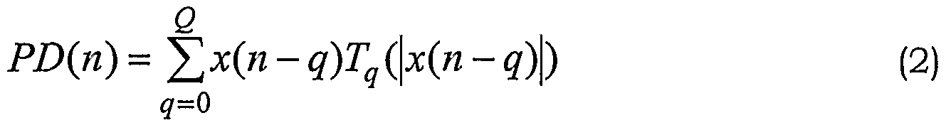
- T q ( ⁇ x(n-q) ⁇ ) are polynomials in the absolute value of the (complex) variable x(n-q).
- which has the same delay q
- this new approach has the advantage that the polynomi- als T q may be sampled at appropriate values of ⁇ x(n-q) ⁇ , as illustrated in Fig. 6, and stored in look-up tables. This will reduce the pre-distorter to a simple FIR filter structure, in which the normally constant filter coefficients are replaced by these look-up tables, as illustrated in Fig. 7.
- the complex input signal x(n) is forwarded to an absolute value block 10 and to a multiplier 12.
- the absolute value signal from block 10 is forwarded to a look-up table LUTO representing a sampled version of polynomial To.
- the corresponding (generally complex) value from look-up table LUTO is for- warded to multiplier 12, where it multiplies the input signal sample x(n).
- Input signal x(n) is also forwarded to a delay block D, where it is delayed one sample period for forming a delayed sample x(n-l). This delayed sample is processed in the same way as the non-delayed sample by an absolute value block 10, a multiplier 12 and a look-up table LUTl.
- look-up table LUTl now represents a sampled version of polynomial Ti instead of To. As illustrated in Fig. 7, further delays and look-up tables may be included (as indicated by the dots in the figure). Finally, the obtained products are added to each other in adders 14 to form the pre-distorted signal PD(n). Look-up tables used in accordance with the present invention make computation in real time much more efficient than the polynomial computation for each sample of the input signal used in [3]. The look-up tables may be updated to keep track of slow changes in the characteristics of the power amplifier.
- a power amplifier with pronounced memory effects was measured and then pre-distorted with a single table pre-distorter (only the first branch with table LUTO in Fig, 7) .
- the simple single table pre-distorter could not resolve the non-symmetry in the measured signal spectrum at the output of the amplifier, although it improved distortion by 5-10 dB.
- the amplifier was then pre-distorted using a double table pre-distorter (the first two branches with tables LUTO and LUTl in Fig. 7). This simple extension to a double table pre-distorter had the effect of resolving the non-symmetry in the measured output signal.
- the improvement compared to a single table was in the order of 10 dB.
- equation (3) is modified to:
- equation (4) may be written as:
- This equation may be rearranged into partial sums containing the same power of z:
- the original polynomials T q ( ⁇ x(n-q) ⁇ ) may be expressed as a series of polynomials Tqm( ⁇ x(n-q) ⁇ ) multiplying different powers of z.
- the pre-distortion may in this approximation be written as;
- a pre-distorter may be implemented by a set of lookup tables in each delay branch, as illustrated in Fig. 8.
- the expressions in the brackets "[ ]" in equation (7) may be viewed as "filter coefficients".
- each delay branch includes 3 look-up tables, for example LUT11, LUT12, LUT13, triggered by the same absolute signal value, ⁇ x(n-l) ⁇ in this case.
- This embodiment also includes a block 16 for calculating the average power z of the input signal.
- Block 16 may also include a smoothing filter (for example a FIR or IIR filter) to prevent abrupt changes in the power signal.
- the power value is forwarded to a multiplier 18 in each branch, where it is multiplied by the value from the corresponding look-up table LUT02, LUTl 2 or LUT22.
- the power value z is also forwarded to a squaring block 20 in each branch.
- a multiplier 22 multiplies the resulting squared power by the value from the corresponding look-up table LUT03, LUTl 3 or LUT23. These products are added in adders 24, and the sums are added to the values from look-up tables LUT01, LUT11 and LUT21 in adders 26.
- the resulting sums from adders 26 form the filter coefficients of the filter structure. From Fig. 8 and equation (7) it is noted that the embodiment of Fig.
- a method for determining the look-up tables is described in the APPENDIX. Since the parameter z is slowly varying, the average power calculated in the common block 16 in the embodiment of Fig. 8 may instead be calculated in each delay branch. Such an embodiment is illustrated in Fig. 9. Although the outputs from blocks 16 may not be identical, they are approximately the same due to the slowly varying average power.
- FIG. 10 Another variation of the embodiment in Fig. 8 is illustrated in Fig. 10. This embodiment eliminates the squaring block 20 by rearranging the order of blocks 18, 22 and 24. It is based on the algebraic identity:
- FIG. 11 A similar variation of the embodiment of Fig. 9 is illustrated in Fig. 11. It is appreciated that further equivalent embodiments may be obtained by other rearrangements of the algebraic expressions in equation (7). For example, instead of performing the multiplications by z and z 2 before the multiplications by the signal and delayed signals, the multiplication order may be reversed.
- Fig. 12 is a block diagram of an exemplary embodiment of a base station including a power amplifier provided with a pre-distorter in accordance with the present invention.
- the baseband complex signal x(n) is forwarded to a pre-distorter 30 in accordance with the present invention.
- the pre-distorted signal is up-converted to intermediate frequency (IF) in a digital up-converter 32 and converted into an analog signal in a D/A converter 34, which in turn is up-converted to radio frequency (RF) by an analog up- converter 36.
- IF intermediate frequency
- RF radio frequency
- the RF signal is forwarded to a power amplifier 38, and the amplified signal is forwarded to an antenna.
- the amplified RF signal is also forwarded to a feedback down-conversion chain including an analog down- converter 40, an A/ D converter 42 and a digital down-converter 44.
- the down- converted feedback signal is forwarded to a trainer 46, which also receives the pre-distorted input signal for determining the look-up tables in pre-distorter 30 in accordance with the mathematical principles described above.
- pre-distorter 30 may, for example, be implemented as in Fig. 8 or 10, but provided with a temperature sensor 48 sensing the power amplifier temperature instead of a power calculation block 16.
- the pre-distorter in accordance with the present invention may be implemented as an FPGA (Field Programmable Gate Array). Another possibility is to use a micro processor or a micro/ signal processor combination and corresponding software. The actual computation of the look-up table entries may be done in an off-line manner at a slow update speed.
- FPGA Field Programmable Gate Array
- x(n) ⁇ may be coarser that the resolution of x(n).
- the input signal amplitude is used as an index into the look-up tables.
- other variables that depend on the input signal amplitude such as the instantaneous input signal power, may also be used.
- the present invention has been described with reference to a FIR filter structure, it is also possible to use the same principles for an IIR (Infinite Impulse Response) filter structure, or a combination of FIR and IIR filter structures.
- IIR Infinite Impulse Response
- the most general filter structure in which the invention may be implemented is a discrete time filter structure.
- a method to compute the tables LUTOO, LUT01, ... is to use already stored tables for certain values of the parameter "z".
- the parameter "z" is assumed to represent power level. However, the method is valid also for other parameters, such as power amplifier (transistor) temperature.
- the tables Tn are derived from equation (A4), which in turn makes use of stored tables Qn.
- Equation (Al) can also, using the inverse matrix elements "c" of equation (A5), explicitly be written as:
- a power amplifier is measured for input and output signals at 3 different power levels: 0 dB, -3 dB and -9 dB.
- tables Qo-2 that work as pre-distorters at their respective power levels are computed.
Abstract
Description


Claims
Priority Applications (3)
| Application Number | Priority Date | Filing Date | Title |
|---|---|---|---|
| EP04717919A EP1611676B1 (en) | 2003-03-25 | 2004-03-05 | Power amplifier pre-distortion |
| AT04717919T ATE519272T1 (en) | 2003-03-25 | 2004-03-05 | POWER AMP PREDISTORTION |
| US10/549,569 US7746955B2 (en) | 2003-03-25 | 2004-03-05 | Power amplifier pre-distortion |
Applications Claiming Priority (2)
| Application Number | Priority Date | Filing Date | Title |
|---|---|---|---|
| SE0300829-9 | 2003-03-25 | ||
| SE0300829A SE525221C2 (en) | 2003-03-25 | 2003-03-25 | Distortion for power amplifiers |
Publications (1)
| Publication Number | Publication Date |
|---|---|
| WO2004086607A1 true WO2004086607A1 (en) | 2004-10-07 |
Family
ID=20290784
Family Applications (1)
| Application Number | Title | Priority Date | Filing Date |
|---|---|---|---|
| PCT/SE2004/000321 WO2004086607A1 (en) | 2003-03-25 | 2004-03-05 | Power amplifier pre-distortion |
Country Status (6)
| Country | Link |
|---|---|
| US (1) | US7746955B2 (en) |
| EP (1) | EP1611676B1 (en) |
| CN (1) | CN100477500C (en) |
| AT (1) | ATE519272T1 (en) |
| SE (1) | SE525221C2 (en) |
| WO (1) | WO2004086607A1 (en) |
Cited By (4)
| Publication number | Priority date | Publication date | Assignee | Title |
|---|---|---|---|---|
| WO2007117187A1 (en) | 2006-04-10 | 2007-10-18 | Telefonaktiebolaget Lm Ericsson (Publ) | A method and apparatus for reducing frequency memory effects in rf power amplifiers |
| FR2954624A1 (en) * | 2009-12-23 | 2011-06-24 | Thales Sa | LINEARIZING DEVICE FOR POWER AMPLIFIER. |
| WO2013007300A1 (en) * | 2011-07-13 | 2013-01-17 | Nokia Siemens Networks Oy | Signal predistortion for non-linear amplifier |
| WO2013051861A1 (en) * | 2011-10-04 | 2013-04-11 | 삼성전자 주식회사 | Digital predistortion apparatus and method using the sum of absolute input signals for a non-identical number of delays |
Families Citing this family (24)
| Publication number | Priority date | Publication date | Assignee | Title |
|---|---|---|---|---|
| US7653147B2 (en) * | 2005-08-17 | 2010-01-26 | Intel Corporation | Transmitter control |
| JP4835241B2 (en) * | 2006-04-11 | 2011-12-14 | 株式会社日立製作所 | Digital predistortion transmitter |
| US20070249290A1 (en) * | 2006-04-24 | 2007-10-25 | Sony Ericsson Mobile Communications Ab | Adaptive pre-distortion |
| US7561857B2 (en) * | 2006-08-30 | 2009-07-14 | Infineon Technologies Ag | Model network of a nonlinear circuitry |
| US7688138B2 (en) * | 2008-03-24 | 2010-03-30 | Harris Corporation | Electronic device having a predistortion filter and related methods |
| EP2169837B1 (en) * | 2008-09-29 | 2013-01-30 | Telefonaktiebolaget LM Ericsson (publ) | Technique for suppressing noise in a transmitter device |
| CN101459647B (en) * | 2009-01-09 | 2011-12-21 | 航天恒星科技有限公司 | Open loop digital base band pre-distorter and pre-distorting method based on frequency band splitting |
| JP5761646B2 (en) | 2009-12-21 | 2015-08-12 | ダリ システムズ カンパニー リミテッド | System and method for modulation agnostic digital hybrid mode power amplifier |
| US8204456B2 (en) | 2010-09-15 | 2012-06-19 | Fujitsu Semiconductor Limited | Systems and methods for spurious emission cancellation |
| GB2490749A (en) * | 2011-05-12 | 2012-11-14 | Nokia Siemens Networks Oy | Linearization of an RF power amplifier using a combined FIR-IIR amplifier model |
| JP6037493B2 (en) * | 2011-10-13 | 2016-12-07 | 株式会社日立国際電気 | Distortion compensation circuit and transmitter using distortion compensation circuit and high-frequency power amplifier |
| JP6098336B2 (en) * | 2012-09-25 | 2017-03-22 | 住友電気工業株式会社 | Distortion compensation device and wireless communication device |
| CN103107967B (en) * | 2013-01-25 | 2016-02-03 | 大唐移动通信设备有限公司 | A kind of update method of pre-distortion coefficients and system |
| WO2014127534A1 (en) * | 2013-02-22 | 2014-08-28 | Telefonaktiebolaget L M Ericsson (Publ) | Method and device for controlling a power amplifier capable of utilizing nonlinearity correction and a power amplifier system |
| US20140250309A1 (en) * | 2013-03-01 | 2014-09-04 | Qualcomm Incorporated | Predictive self calibrated power control |
| US20140333376A1 (en) * | 2013-05-09 | 2014-11-13 | King Fahd University Of Petroleum And Minerals | Scalable digital predistortion system |
| US9379744B2 (en) | 2014-09-16 | 2016-06-28 | Honeywell International Inc. | System and method for digital predistortion |
| EP3197113B1 (en) * | 2014-11-14 | 2020-06-03 | Huawei Technologies Co. Ltd. | Analog predistorter core module and analog predistorter system |
| US9749161B1 (en) * | 2016-02-23 | 2017-08-29 | Nxp Usa, Inc. | Fixed-point conjugate gradient digital pre-distortion (DPD) adaptation |
| EP3665773A1 (en) * | 2017-08-11 | 2020-06-17 | Nokia Solutions and Networks Oy | Polyphase digital signal predistortion in radio transmitter |
| US10469109B2 (en) * | 2017-09-19 | 2019-11-05 | Qualcomm Incorporated | Predistortion for transmitter with array |
| US10396723B1 (en) | 2018-03-30 | 2019-08-27 | Northrop Grumman Systems Corporation | Multirate, iterative, memory polynomial based modeling and pre-distortion of high bandwidth power amplifiers |
| US10985951B2 (en) | 2019-03-15 | 2021-04-20 | The Research Foundation for the State University | Integrating Volterra series model and deep neural networks to equalize nonlinear power amplifiers |
| CN110535797B (en) * | 2019-08-23 | 2022-01-28 | 北京无极芯动科技有限公司 | Reconfigurable digital predistortion processing module |
Citations (4)
| Publication number | Priority date | Publication date | Assignee | Title |
|---|---|---|---|---|
| US5867065A (en) * | 1997-05-07 | 1999-02-02 | Glenayre Electronics, Inc. | Frequency selective predistortion in a linear transmitter |
| US6141390A (en) * | 1997-05-05 | 2000-10-31 | Glenayre Electronics, Inc. | Predistortion in a linear transmitter using orthogonal kernels |
| US6356146B1 (en) * | 1999-07-13 | 2002-03-12 | Pmc-Sierra, Inc. | Amplifier measurement and modeling processes for use in generating predistortion parameters |
| GB2376613A (en) * | 2001-06-15 | 2002-12-18 | Wireless Systems Int Ltd | Signal distortion correction using predistortion |
Family Cites Families (10)
| Publication number | Priority date | Publication date | Assignee | Title |
|---|---|---|---|---|
| US3356146A (en) * | 1965-06-23 | 1967-12-05 | Schlumberger Technology Corp | Well logging tool |
| US4816914A (en) * | 1987-01-07 | 1989-03-28 | Pictel Corporation | Method and apparatus for efficiently encoding and decoding image sequences |
| US5832022A (en) | 1995-06-02 | 1998-11-03 | Omnipoint Corporation | Method and apparatus for controlling the modulation index of continuous phase modulated (CPM) signals |
| EP0813300A1 (en) | 1996-06-12 | 1997-12-17 | Loral Aerospace Corporation | Signal conditioner with symbol addressed lookup table based transversal filters |
| FI105506B (en) | 1998-04-30 | 2000-08-31 | Nokia Networks Oy | Linearization procedure for amplifiers and amplifier arrangements |
| US6404823B1 (en) | 1998-07-01 | 2002-06-11 | Conexant Systems, Inc. | Envelope feedforward technique with power control for efficient linear RF power amplification |
| US6275685B1 (en) | 1998-12-10 | 2001-08-14 | Nortel Networks Limited | Linear amplifier arrangement |
| US7397850B2 (en) * | 1999-02-18 | 2008-07-08 | Easley Mathew F | Reciprocal index lookup for BTSC compatible coefficients |
| US6614854B1 (en) * | 1999-05-28 | 2003-09-02 | Carriercomm, Inc. | System and method for adaptive predistortion |
| US7269231B2 (en) * | 2002-05-31 | 2007-09-11 | Lucent Technologies Inc. | System and method for predistorting a signal using current and past signal samples |
-
2003
- 2003-03-25 SE SE0300829A patent/SE525221C2/en unknown
-
2004
- 2004-03-05 AT AT04717919T patent/ATE519272T1/en not_active IP Right Cessation
- 2004-03-05 US US10/549,569 patent/US7746955B2/en not_active Expired - Fee Related
- 2004-03-05 WO PCT/SE2004/000321 patent/WO2004086607A1/en active Application Filing
- 2004-03-05 CN CNB2004800143508A patent/CN100477500C/en not_active Expired - Fee Related
- 2004-03-05 EP EP04717919A patent/EP1611676B1/en not_active Expired - Lifetime
Patent Citations (4)
| Publication number | Priority date | Publication date | Assignee | Title |
|---|---|---|---|---|
| US6141390A (en) * | 1997-05-05 | 2000-10-31 | Glenayre Electronics, Inc. | Predistortion in a linear transmitter using orthogonal kernels |
| US5867065A (en) * | 1997-05-07 | 1999-02-02 | Glenayre Electronics, Inc. | Frequency selective predistortion in a linear transmitter |
| US6356146B1 (en) * | 1999-07-13 | 2002-03-12 | Pmc-Sierra, Inc. | Amplifier measurement and modeling processes for use in generating predistortion parameters |
| GB2376613A (en) * | 2001-06-15 | 2002-12-18 | Wireless Systems Int Ltd | Signal distortion correction using predistortion |
Cited By (10)
| Publication number | Priority date | Publication date | Assignee | Title |
|---|---|---|---|---|
| WO2007117187A1 (en) | 2006-04-10 | 2007-10-18 | Telefonaktiebolaget Lm Ericsson (Publ) | A method and apparatus for reducing frequency memory effects in rf power amplifiers |
| FR2954624A1 (en) * | 2009-12-23 | 2011-06-24 | Thales Sa | LINEARIZING DEVICE FOR POWER AMPLIFIER. |
| EP2341614A1 (en) * | 2009-12-23 | 2011-07-06 | Thales | Linearization device for a power amplifier |
| US8432220B2 (en) | 2009-12-23 | 2013-04-30 | Thales | Linearization device for a power amplifier |
| WO2013007300A1 (en) * | 2011-07-13 | 2013-01-17 | Nokia Siemens Networks Oy | Signal predistortion for non-linear amplifier |
| KR20140040270A (en) * | 2011-07-13 | 2014-04-02 | 노키아 지멘스 네트웍스 오와이 | Signal predistortion for non-linear amplifier |
| US9362869B2 (en) | 2011-07-13 | 2016-06-07 | Nokia Solutions And Networks Oy | Signal predistortion for non-linear amplifier |
| KR101700725B1 (en) * | 2011-07-13 | 2017-01-31 | 노키아 솔루션스 앤드 네트웍스 오와이 | Signal predistortion for non-linear amplifier |
| WO2013051861A1 (en) * | 2011-10-04 | 2013-04-11 | 삼성전자 주식회사 | Digital predistortion apparatus and method using the sum of absolute input signals for a non-identical number of delays |
| US9203355B2 (en) | 2011-10-04 | 2015-12-01 | Samsung Electronics Co., Ltd | Digital predistortion apparatus and method using the sum of absolute input signals for a non-identical number of delays |
Also Published As
| Publication number | Publication date |
|---|---|
| ATE519272T1 (en) | 2011-08-15 |
| US20060133536A1 (en) | 2006-06-22 |
| SE0300829D0 (en) | 2003-03-25 |
| EP1611676A1 (en) | 2006-01-04 |
| CN1795607A (en) | 2006-06-28 |
| SE0300829L (en) | 2004-09-26 |
| EP1611676B1 (en) | 2011-08-03 |
| US7746955B2 (en) | 2010-06-29 |
| SE525221C2 (en) | 2004-12-28 |
| CN100477500C (en) | 2009-04-08 |
Similar Documents
| Publication | Publication Date | Title |
|---|---|---|
| EP1611676B1 (en) | Power amplifier pre-distortion | |
| US11129076B2 (en) | Method and system for baseband predistortion linearization in multi-channel wideband communication systems | |
| US7170342B2 (en) | Linear power amplification method and linear power amplifier | |
| US8787494B2 (en) | Modeling digital predistorter | |
| EP2131491B1 (en) | Predistortion with sectioned basis functions | |
| US6956433B2 (en) | Polynomial predistorter using complex vector multiplication | |
| US7412469B2 (en) | Power amplifier pre-distorter training | |
| EP2837093B1 (en) | Digital predistorter (dpd) structure based on dynamic deviation reduction (ddr)-based volterra series |
Legal Events
| Date | Code | Title | Description |
|---|---|---|---|
| AK | Designated states |
Kind code of ref document: A1 Designated state(s): AE AG AL AM AT AU AZ BA BB BG BR BW BY BZ CA CH CN CO CR CU CZ DE DK DM DZ EC EE EG ES FI GB GD GE GH GM HR HU ID IL IN IS JP KE KG KP KR KZ LC LK LR LS LT LU LV MA MD MG MK MN MW MX MZ NA NI NO NZ OM PG PH PL PT RO RU SC SD SE SG SK SL SY TJ TM TN TR TT TZ UA UG US UZ VC VN YU ZA ZM ZW |
|
| AL | Designated countries for regional patents |
Kind code of ref document: A1 Designated state(s): BW GH GM KE LS MW MZ SD SL SZ TZ UG ZM ZW AM AZ BY KG KZ MD RU TJ TM AT BE BG CH CY CZ DE DK EE ES FI FR GB GR HU IE IT LU MC NL PL PT RO SE SI SK TR BF BJ CF CG CI CM GA GN GQ GW ML MR NE SN TD TG |
|
| 121 | Ep: the epo has been informed by wipo that ep was designated in this application | ||
| WWE | Wipo information: entry into national phase |
Ref document number: 2004717919 Country of ref document: EP |
|
| ENP | Entry into the national phase |
Ref document number: 2006133536 Country of ref document: US Kind code of ref document: A1 |
|
| WWE | Wipo information: entry into national phase |
Ref document number: 10549569 Country of ref document: US |
|
| WWE | Wipo information: entry into national phase |
Ref document number: 4305/DELNP/2005 Country of ref document: IN |
|
| WWE | Wipo information: entry into national phase |
Ref document number: 20048143508 Country of ref document: CN |
|
| WWP | Wipo information: published in national office |
Ref document number: 2004717919 Country of ref document: EP |
|
| WWP | Wipo information: published in national office |
Ref document number: 10549569 Country of ref document: US |