SYSTEM ANJ> METHOD FOR HOME AGENT LOAD BALANCING
CROSS REFERENCE TO RELATED APPLICATION
This application claims priority to U.S. Patent Application Serial No. 10/222,547 filed on August 16, 2002, the entire teaching of which is incorporated herein by reference.
FIELD OF THE INVENTION
The present invention relates to communications in mobile internet Protocol ("IP") networks. More particularly, it relates to load balancing of home agents in a mobile IP network.
BACKGROUND OF THE INVENTION The Internet Protocol ("IP") is an addressing protocol designed to route traffic within a network or between networks. The Internet Protocol is used on many computer networks including the Internet, intranets and other networks. Internet Protocol addresses are typically assigned to "immobile" nodes on a network. An immobile node may be moved to a different computer network, but is typically associated with a static physical location (e.g., 3Com Corporation in Santa Clara, California) and an immobile Internet protocol address.
The Mobile Internet Protocol (hereinafter Mobile IP) allows "mobile" nodes to transparently move between different Internet Protocol sub-networks ("subnets"). Internet Protocol addresses are typically assigned to mobile nodes based on their home Internet Protocol subnet. The home subnet is connected to an external network (e.g., the Internet or an intranet) with a "home agent" that serves as the subnet's gateway router. As is known in the art, the gateway connects computer networks using different networking protocols or operating at different transmission capacities. As is known in the art, a router translates differences between network protocols and routes data packets to an appropriate network node or network device.
When a mobile node "roams" (i.e., dynamically changes its physical location), it periodically transmits "agent solicitation" messages to other gateway routers. A mobile node also listens for "agent advertisement" messages from other gateway routers. When a mobile node receives an agent advertisement message indicating that it is now on a foreign subnet, it registers with the foreign gateway router or "foreign agent" and its home agent. The registration with the home agent indicates that the mobile node is away from "home" (i.e., away from its
home subnet). The registration with the foreign agent allows the mobile node to receive data on the foreign subnet.
The Mobile Internet Protocol allows a mobile node to dynamically change its network connectivity in a manner that is transparent to protocol layers above the Internet Protocol layer, for example, without re-establishing Transmission Control Protocol ("TCP") or User Datagram Protocol ("UDP") sessions. As is known in the art, Transmission Control Protocol and User Datagram Protocol are often used over .Internet Protocol in computer networks. Transmission Control Protocol provides a connection-oriented, end-to-end reliable protocol designed to fit into a layer hierarchy of protocols that support multi-network applications. User Datagram Protocol provides a transaction oriented datagram protocol, where delivery and duplicate packet protection are not guaranteed.
It is often desirable to establish a voice, video and/or data call from a mobile node that has roamed from its home network to a foreign network. Such a voice, video or data call is typically established using call control and other protocols such as Session Initiation Protocol ("SIP"), H.323, Authentication, Authorization and Accounting ("AAA"), e.g., for billing, Domain Name System ("DNS"), e.g., for IP address decoding, etc.
A mobile node registers with it's home agent using a Mobile IP Registration Request message. As a result, its home agent can create or modify a mobility binding record for that mobile node. A mobility binding record is used to keep track of mobile communications information such as a home network address of a mobile node on a home network, a care-of- address for the mobile node on a foreign network, a lifetime timer for the association between the home network address and the care-of-network address, and other types of mobile communication information.
Mobile Internet Protocol requires link layer connectivity between a mobile node and a foreign agent. However, in some systems, the link layer from the mobile node may terminate at a point distant from a foreign agent. Such networks are commonly referred to as third generation ("3G") networks. Third-generation networks support data rates ranging from 144 bits-per- second to 2M bits-per-second, packet switched services including DP traffic, multimedia services including video conferencing and streaming video, or international roaming among different third generation operating environments. Third generation networks include packet-based transmission of digitalized voice, data and video, and encompass a range of wireless technologies including Code Division Multiple Access. ("CDMA"), Universal Mobile Telecommunications Service ("UMTS"), Wide-band CDMA ("WCDMA") and others.
As is known in the art, CDMA is a digital communications technology that uses spread- spectrum communication techniques. CDMA does not assign a specific frequency to each user. Instead, every CDMA communication channel can use the full available communications spectrum, and individual conversations are encoded with a pseudo-random digital sequence. UMTS is a third generation technology that delivers broadband information at speeds up to 2M bps. Besides voice and data, UMTS delivers audio and video to wireless devices anywhere in the world through fixed, wireless and satellite systems.
WCDMA is an International Telecommunications Unit ("ITU") standard derived from the code division multiple access and offers high data speeds to mobile devices. WCDMA supports mobile/portable voice, images, data, and video communications at up to 2M bps. The input signals are digitalized and transmitted in coded, spread-spectrum mode over a broad range of frequencies using a 5MHz-wide carrier compared with 200 kHz-wide carrier that is used for narrowband CDMA.
In many Mobile IP systems, home agents are managed by home agent control nodes. A home agent control node typically manages multiple home agents. Figure 1 is a block diagram illustrating a network architecture 100 that may be used in a third generation wireless network using a home agent control node. The network 100 includes a plurality of mobile nodes ("MNs"), one of which is shown as a mobile node 102, a base station ("BS") 106, a packet control function ("PCF") 106, a plurality of packet data serving nodes ("PDSNs"),, one which is shown as a packet data serving node 108, a plurality of home agents ("HA"), one of which is shown as a home agent 110, a home agent control node ("HACN") 112, a home AAA ("HAAA") server 114, and a foreign AAA ("FAAA") server 116.
The PCF 106 may be located on a radio network node that terminates a physical link layer to and from the mobile node 102. The packet data serving node 108 provides routing services for the mobile node 102 while it is registered with the home agent 110. The packet data serving node 108 de-tunnels and delivers datagrams that were tunneled from the home agent 110 via an IP network, for instance, to the mobile node 102. The PDSN 108 may perform any foreign agent function with the mobile node 102 and pass messages to the HACN 112.
The packet data serving node 108 may be a terminating point for PPP messages from the mobile node 102. The packet data serving node 108 may communicate directly with a network, such as a radio access network including the packet control function 106, and receive PPP data from the mobile node 102 through the network. The packet data serving node 108 may then assemble and decapsulate the PPP packets to get the IP packets.
The home agent 110 may maintain current location information of the mobile node 102. The home agent 110 may perform authentication and registration functions to determine whether the mobile node is authorized to access the home network. The authentication process may
involve checking the authentication of the mobile node 102, identification of the user, authenticating the user, or checking whether the mobile node's account has been paid, for instance. The home agent 110 may also tunnel data from a target host to the packet data serving node 108 and provide tunneling services in the reverse direction, i.e., provide packet re- addressing for traffic from the packet data serving node to the host.
The functions of the FAAA 116 may be implemented with a processor executing computer instructions stored in a memory. The FAAA 116 may authenticate the mobile user logging onto the PDSN 108, provide to the PDSN 108 specific configuration options for the user, and provide routing information to the MD? registration packets (i.e., to specify to which HA/HACN a registration request is to be forwarded). A shared secret may exist between the
PDSN 108 and the FAAA 116 so that the messages between the two nodes can be authenticated.
The FAAA 116 may act as a proxy for the HAAA 114, in the network service provider's domain since the PDSN 108 does not typically communicate with the HAAA 114, which is in the home network of the mobile node 102. All authentication requests sent to the FAAA 116 may be sent to the HAAA 114, and the HAAA 114 may respond to the authentication request to the FAAA 116, and the FAAA 116 may then send it back to the PDSN 108. A shared secret may exist between the FAAA 116 and the HAAA 114 for authenticating messages being sent between the two entities.
The functions of the HACN 112 may be implemented with a processor executing computer program instructions stored in a memory, and may manage a plurality of home agent control nodes. In the exemplary network architecture 100, when a user of the mobile node 102 initiates a call session, the mobile node 102 establishes a traffic channel with the base station 104. The base station 104 may in turn communicate with the packet control function 106. Then, the packet control function 106 selects one of the packet data serving nodes, such as the packet
data serving node 108, and establishes a routing protocol ("RP") channel to the packet data serving node 108. Once the RP channel is established, the mobile node 102 establishes a point- to-point protocol ("PPP") session with the packet data serving node 108. Once the PPP session is established, the mobile node 102 may send a registration request to the packet data serving node 108. When the packet data serving node 108 receives the registration request, the packet data serving node 108 communicates with the FAAA 116 to determine to which HACN to forward the registration request to. Based on the information received from the FAAA 116, the PDSN 108 may forward the request to the HACN 112, and the HACN 112 may determine a HA to which it should forward the registration request to. When the HACN 112 receives the registration request, the HACN 112 may determine a
HA based on a number of criteria. For example, the registration request may specify a HA, and the HACN 112 may forward the request to that HA. If no such information is specified in the request, the HACN, 112 may determine a HA based on other factors, such as loads on the available HAs that are periodically conveyed to the HACN 112 via heartbeat messages, for instance. In such an embodiment, the HACN 112 may select the least loaded HA, and then may forward the request to the selected HA. When the HA receives the registration request, the HA may authenticate the mobile node 12, process the registration request, send a registration response, and establish a call. Once the call is established, the PDSN 112 may directly communicate with the HA. However, there are several problems with selecting a HA from a group of HAs using a single HACN. Firstly, such a method may result in a bottle neck, since a single HA is limited as to how many registration requests may be processed in a second. Secondly, using a primary HACN and a secondary HACN, when the primary HACN fails, it may take a finite time for the secondary HACN to detect the failure of the primary HACN and take over the functionality of
the primary HACN. However, this delay in changing roles of the secondary and primary HACNs can lead to the loss of functionality for a brief period of time depending upon a heartbeat rate between the primary and secondary HACNs. Additionally, if a provider uses a single HACN, a failure of that HACN may bring down a bank of HAs that are managed at the HACN.
Thus, a need exist for an improved method and system for selecting a HA from a plurality of HAs.
SUMMARY OF THE INVENTION
The system and method for selecting a home agent in a mobile IP network are developed.
One method for selecting a home agent from a plurality of home agents in a mobile D? network includes establishing a distributed load information database on a plurality of home agents, receiving a mobile IP registration request message on a first home agent of the plurality of home agents, and, at the first home agent, using a load information database of the first home agent and a current load of the first home agent to load balance the mobile P registration request between the first home agent and at least, one second home agent of the plurality of home agents.
One exemplary system for selecting a home agent in a mobile IP network includes a plurality of home agents configured to receive system load information, where a first home agent of the plurality of home agents is configured to receive a mobile IP registration request message associated with a mobile node in the mobile IP network, and, respectively, the first home agent is configured to use the system load information to load balance the mobile LP registration request message between the plurality of home agents. These as well as other aspects and advantages of the present invention will become more apparent to those of ordinary skill in the art by reading the following detailed description, with reference to the accompanying drawings.
BRIEF DESCRIPTION OF THE DRAWINGS
Exemplary embodiments of the present invention are described with reference to the following drawings, in which:
Figure 1 is a functional block diagram illustrating an example of a prior art mobile IP
network architecture;
Figure 2 is a functional block diagram illustrating an embodiment of a network system suitable for application in the present invention;
Figure 3 is a block diagram illustrating another embodiment of a network system suitable for application in the present invention; Figure 4 is a block diagram of an access node in accordance with one embodiment of the present invention;
Figure 5 is a block diagram illustrated a distributed architecture of the access node according to one embodiment of the present invention;
Figure 6 is a block diagram illustrating a control chassis in the access node according to one embodiment of the present invention;
Figure 7 is a block diagram illustrating a data chassis in the access node according to one embodiment of the present invention;
Figure 8 is a block diagram illustrating exemplary physical interconnections of the system control bus according to one embodiment of the present invention; Figure 9 is a block diagram illustrating physical interconnections of a media data bus according to one embodiment of the present invention;
Figure 10 is a block diagram illustrating an inter-shelf cabling topology according to one embodiment of the present invention;
Figure 11 is a block diagram of a message sequence scenario illustrating a heartbeat mechanism between a HACN and a HA according to one embodiment of the present invention;
Figure 12 is a block diagram of a message sequence scenario illustrating a mobile IP registration process between a MN and a HA according to one embodiment of the present invention;
Figure 13 is a block diagram of a message sequence scenario illustrating a mobile LP registration process between a MN and a HA according to one embodiment of the present invention in which an average load on the HA is higher than an average system load;
Figure 14 is a block diagram of a message sequence scenario illustrating a mobile IP registration process between a MN and a HA according to one embodiment of the present invention in which an average load on the HA is higher than an average system load, and further in which the HA is unable to determine another HA to service the registration request; and
Figure 15 is a block diagram of a message sequence scenario illustrating a mobile IP registration process between a MN and a HA according to one embodiment of the present invention in which a static MN IP address of the MN does not belong to an address pool on the HA.
THE DETAILED DESCRIPTION OF THE PREFERRED EMBODIMENTS
Figure 2 is a functional block diagram illustrating an embodiment of a network system
200 suitable for application in the present invention for selecting home agents for mobile nodes in a mobile IP network. It should be understood that this and other arrangements and processes described herein are set forth for purposes of example only, and other arrangements and elements
(e.g., interfaces, functions, order of elements, etc.) can be used instead and some elements may be omitted altogether. Further, as in most telecommunications applications, those skilled in the art will appreciate that many elements described herein are functional entities that may be implemented as discrete components or in conjunction with other components, in any suitable combination or location.
As shown in Figure 2, the system 200 includes a mobile node 202, a base station 204, a packet control function 206, a bank of PDSNs, one of which is a PDSN 208, a bank of HAs, one of which is a HA 210, a home agent control entity illustrated as a HACN 212, a HAAA 214, and a FAAA 216.
In one embodiment, the exemplary system is implemented as using equipment from Commworks (a 3Com company). For example, the exemplary system 200 may be implemented using a Commworks 3G Data System including a Total Control Hub by 3Com Corporation of Santa Clara, California including Commworks Total Control Hub 1000 or 2000, a Steel-Belted RADIUS Advanced Wireless Edition AAA Server, Signaling Control Nodes; Total Control 1000 or 2000 Home Agent Card Set and Packet Data Serving Node Set, and Home Agent Control Nodes. However, the exemplary embodiments are not limited to such equipment, and the exemplary system 200 could also be implemented using equipment from Cisco Systems of San Jose, California, Lucent Technologies of Murray Hill, New Jersey, Ascend Communications of
Alameda, California, Motorola, Inc. of Schaumburg, Illinois, Nokia Corporation of Helsinki, Finland, Ericsson Corporation of Stockholm, Sweden, and others.
The mobile node 202 may take any suitable form, such as, for instance, a telephone, a laptop computer, a fax, or a personal digital assistant ("PDA"), for instance. The mobile node 202 is connected to the base station 204. The base station 204 may reside on a radio network such as a CDMA radio network. The base station 204 is coupled to the PCF that selects a PDSN for a new incoming user communication session. For example, the PCF may be preprogrammed with one or more IP addresses of PDSNs. The PDSN 208 is coupled to the FAAA 216 and the HA 210. The HA 210 is coupled to the HACN 210 and the HAAA 214. The HAAA 214 is coupled to the FAAA 216. The system illustrated in Figure 2 includes elements of a 3G network. However, it will be recognized that the exemplary embodiments for HA selection are in no way limited to 3G networks. For example, the exemplary embodiments could also be used in 2.5G networks or later developed networks.
The PDSN 208 may receive registration request messages from the mobile node 102 and may perform any foreign agent functionality between the mobile node 102 and the HA 210. For instance, the PDSN 208 may pass registration request messages to the HAs.
The HACN 212 may include a plurality of HACNs 212, including an active HACN and one or more standby HACNs. If the active HACN 212 fails, the standby HACN may be activated. For example, if the standby HACN detects the failure of the active HACN (responsively to not receiving one or more heartbeat status messages from the active HACN), the standby HACN may takeover the role, of the active HACN. The functions of the HACN 212 may be implemented with a processor executing computer instructions stored in a memory.
According to an exemplary embodiment, the HACN 212 maintains a heartbeat mechanism with the HAs and does not actively handle registration requests. Instead, the HACN
212 collects statistical information, such as a number of calls, memory utilization, or CPU utilization, from each HA communicating with the HACN 212. The HACN 212 may then process the statistical information to determine an average system load and one or more least loaded HAs. Alternatively, in an embodiment, in which HAs are divided into groups of HAs configured to handle predetermined types of calls, such as high-speed or high-bandwidth calls, the HACN 212 may determine the least loaded HAs in each of these groups. Further, according to an exemplary embodiment, the HACN 212 may pass load information, such as the average system load and one or more lists of least loaded HAs, to each HA associated with the HACN 212. It should be understood that an overall system load may include an average CPU load, an average memory load, or an average call session load. For example, as illustrated in Figure 2, the HACN 212 may pass that information to the bank of HAs including the HA 210. Each of the HAs may then use the received system load information to route incoming registration requests to itself or to another HA, the embodiments of which will be described in greater detail below.
Thus, according to an exemplary embodiment, when a user of the mobile node 202 initiates a communication session, the mobile node 202 establishes a traffic channel with the BS 204. The BS 204. then communicates with the PCF 206, and the PCF 206 selects one of the PDSNs, such as the PDSN 208, and establishes an RP session to the PDSN 208. Once the RP channel is set up, the mobile node 202 establishes a Point-to-Point Protocol ("PPP") session with the PDSN 208. Then, the mobile node 202 sends a registration request to the PDSN 208. Responsively to receiving the registration request, the PDSN 208 may contact the FAAA 216 to authenticate the mobile node or the user of the mobile node, and also to deteπnine a HA to which the PDSN 208 should forward the registration request to. Based on the information provided by the FAAA 216, the PDSN 208 may forward the registration request to the HA 210.
According to an exemplary embodiment, when the HA 210 receives the registration request, the HA 210 may determine if its average call load (including a number of calls, a memory usage load, or a CPU usage load, for instance) is lower than the average system load that was provided by the HACN 212. If the average load of the HA 210 is lower than the average system load, or if the registration request requires the HA 210 to handle the registration request, the HA 210 may process the registration request. If none of the previous conditions is satisfied, or the call is a predetermined, type of call that is not handled by the HA 210, the HA 210 may forward the registration request to the least loaded HA in the system, or the least loaded HA configured to handle the type of the call session that is being setup from the MN 202. The selected HA may process the registration request and respond with a registration reply that is sent to the MN 202.
According to an exemplary embodiment, each HA, such as the HA 210, upon boot up, may perform heartbeat operations with a HACN, such as the HACN 212, and heartbeat messages may be used to determine non-availability of a HA by a HACN. In a similar manner, no reply to a heartbeat sent from the HACN to the HA may be treated as a HACN failure. Additipnally, according to an exemplary embodiment, a heartbeat request that the HA 210 sends to the HACN 212 includes current load information on the HA 210, and a heartbeat response sent from the HACN 212 includes one or more list of least loaded HAs and an average system load parameter indicating an average system load (i.e., an average system load computed on the HACN 212 based on loads of HAs communicating with the HACN 212 and accessible from the HA 210).
Heartbeat messages sent between the HACN 212 and the HA 210 may be validated for integrity, and may also be authenticated by using a shared secret between the HA 210 and the HACN 212. A shared secret may be a byte string including alphanumerical characters, for instance, and may be configured on both the HACN 212 and the HA 210. Once the HA 210
undergoes initialization, the HA 210 may initiate a heartbeat mechanism. A heartbeat time period may be assigned by the HACN 212 during the initialization process or upon receiving a first heartbeat message from the HA 210. In such an embodiment, the HA 210 may send a Heartbeat Request message to the HACN 212 every time its heartbeat timer expires. Responsively to receiving the Heartbeat Request, the HACN 212 may respond with a Heartbeat Acknowledgement message. If no Acknowledgement message is received, the HA 210 may assume that the HACN 212 is non-operational.
Figure 3 is a block diagram illustrating another_embodiment of a network architecture 300 suitable for application in the system for selecting home agents for mobile nodes in a mobile IP network. The system includes a mobile node 302, a base station 304, a PCF 304, a plurality of PDSNs, one of which a PDSN 308 is shown, an LP network 310, an FAAA server 314, a HAAA server 316, and a target host 312. The system further includes an access node 318 that is a multi-service platform configured to deliver data services to mobile nodes. According to an exemplary embodiment, the access node 318 includes a plurality of HAs, two of which a HA 320 and a HA 322 are shown, and a home agent control entity, illustrated as a system manager 324. The HAs 320 and 322 communicate with the system manager 324 and send their load information, for instance, and receive average system load information from the system manager 324.
Figure 4 is a block diagram illustrating an exemplary embodiment of the access node 318. The access node 318 illustrated in Figure 3 may be configured on a single rack 450 composed of three shelves, a control shelf 402 and two data shelves 404 and 406. The control shelf 402 is composed of a plurality of cards (0-N) that will be described in greater detail in reference to subsequent Figures. The control shelf 402 may be coupled to a network management system via a network management interface 408, thus, enabling system operators to
configure the access node 318 according to their systems' needs. The control shelf 402 further includes an interface 410 to a network 416. In one embodiment, the network 416 may be the CDMA network, the PSTN/TDM, or the ATM network, or a data network, such as the Internet, for instance. However, different networks could also be used. In one embodiment, each card in the control chassis may include two ports, such as two Gigabit Ethernet ports that may be used for communicating data to and from the network 416.
Further, the access nodes 318 illustrated in Figure 3 include two data shelves 404 and 406 having a plurality of cards (0-N) that will be also described in greater detail in reference to subsequent Figures. The data shelves 404 and 406 include interfaces 412 and 414 to the network 416. It should be understood that Figure 4 shows only some of the external interfaces and does not illustrate connections between the chassis. Further, it should be understood that the present invention is not limited to a single rack including three chassis, and more chassis could also be added to the single rack.
Alternatively, the access node 318 may be distributed over a plurality of racks. In such a configuration, one control shelf may control a number of data shelves distributed over a plurality of racks. Figure 5 is a block diagram illustrating a distributed network architecture 500 of the access node 318. In addition to the rack 450 illustrated in Figure 4, the access node 318 further includes a second rack 550. The second rack 550 contains three data shelves 502, 504, and 506 communicating with the network 416 via interfaces 508, 510, and 512, and, further, communicating with the network 416 via interfaces 514, 516, and 518, respectively. It should be understood that the present invention is not limited to two racks, and more than two racks could also be used.
Figure 6 is a block diagram illustrating a control shelf 600 according to one exemplary embodiment. The control shelf 600 illustrated in Figure 6 includes 18 card slots; however, it
should be understood that the control shelf is not limited to such a configuration, and it is possible that some slots could remain unused and not get populated with any cards, or fewer card slots could also be used. According to an exemplary embodiment, all components of the control shelf 600 may exhibit a redundancy, such as 1 to 1 redundancy, and may have failover capabilities. Thus, each component of the control shelf 600 may include an active card and a standby card so that, if the active card fails, the standby card may detect the failure and take over the role of the active card, the embodiments of which will be described in greater detail below.
The control shelf 600 includes two shelf controllers 602 and 604, and each shelf controller is supported on dedicated hardware in the form of two half-height cards located in the leftmost slots of the shelf 600. Further, the control shelf 600 includes two switch egress modules 606 and 608, two system managers 610 and 612, and a plurality of application cards, HA cards 614-636.
According to an exemplary embodiment, the shelf controller 602 may be configured as a primary shelf controller, and the shelf controller 604 may be configured as a backup shelf controller. Each shelf controller contains a multi-layer (L2/L3) capable switch that is used to connect the shelf controller to each card slot in the shelf. Further, each shelf controller may have a separate bus to each slot, i.e., a system control bus, hereinafter also referred to as a management bus, that is used to provide intra and inter card control communication, such as management, signaling, and routing, within a single platform. According to one embodiment, for instance, a HA card may communicate with one or more system manager cards or another HA card using the system control bus. In such an embodiment, data sent from the HA is communicated via the system control bus, one or more shelf controller cards to the destination such as one or more system manager cards or the HA card. Similarly, the system manager cards may communicate data, such as load information data, to one or more HA cards via the system
controller bus. In such an embodiment, the data is communicated from the system manager card via the system controller bus and the shelf controller cards to the destination.
In one embodiment, the system control bus may be implemented as a switched Fast Ethernet (100 Mbps) system control bus that provides a physically separate ana" dedicated embedded network to support management and control functions of the platform. The system control bus originates from each of two shelf controller modules in the shelf to each slot, including the peer shelf controller slot. For instance, each shelf controller may be connected to every switch egress and application module in the shelf via one bi-directional 100Base T-TX Ethernet link. Additionally, two shelf controller modules may be connected via one bi- directional 100Base T-TX Ethernet link. In one embodiment, each connection may be configured as a pair of differential traces carrying 100Mbps 100BaseT -TX Ethernet. Thus, in such an embodiment, each system control bus link may be a 4-wire interface including one pair of TX and one pair of RX Fast Ethernet links. However, it should be understood that different types of links could also be used. The shelf controllers 602 and 604 manage the intra-shelf hardware configurations and hardware management. For example, the shelf controllers may read a shelf identifier and a shelf serial number that may then be used to facilitate assignment of internal addresses and allow the system managers to correctly associate specific card locations and configurations. Further, the shelf controllers 602 and 604 provide physical monitoring in the form of presence detection for the other card in the shelf and power sources.
The shelf controllers 602 and 604 may. also poll the status of power sources, cooling fans, or temperature sensors provided in the power sources, for instance. Additionally, the shelf controllers 602 and 604 may be responsible for power management within the shelf 600 by evaluating the current requirements of the individual cards against the current available power
available in the power sources. The shelf controllers 602 and 604 may communicate with all cards in the shelf 600 via an Ethernet interface 642, such as a 100 Mbps or a faster interface.
The switch egress modules 606 and 608 may be configured as high-speed point-to-point switches (L2/L3) that allow all cards in the slots, such as the system managers and PDSNs/HAs, to communicate with one another on a gigabit link. The switch egress modules 606 and 608 employ switch network interfaces 638 and 640 to communicate data to and from the network.
Further, the control chassis 600 includes the system managers 610 and 612 that may employ any existing or later developed management protocols, such as a Simple Network Management Protocol, to manage multiple chassis from a single point. The system managers 610 and 612 may maintain statistics and status information of all cards in the system by periodically polling each card using SNMP, for instance. Further, according to an exemplary embodiment, the system managers 610 and 612 may maintain load information of each HA card that is provided from each HA using heartbeat messages, for instance. Then, the system managers 610 and 612 may use the received load information to compute an average system load and may provide that information to each HA via heartbeat response messages, the embodiments of which will be later described in greater detail. The system managers 610 and 612 may communicate with each card via interfaces 644 and 646, respectively. Further, each HA card has a network interface, i.e., network interfaces 648-670 illustrated in Figure 6.
Figure 7 is a block diagram illustrating a data shelf 700 according to one exemplary embodiment. The data shelf 700 includes shelf controllers 702 and 704 communicating via an interface 742 with all cards in the shelf 700. The data shelf 700 further includes two switch egress modules 706 and 708 communicating via switch network interfaces 738 and 740, and HAs 710-736 communicating via interfaces 744-770.
Figure 8 illustrates exemplary physical interconnections of the system control bus according to one exemplary embodiment. As illustrated in Figure 8, the system control bus interconnects two shelf controllers 806 and 808 to each other, to each switch egress module 802 and 804, as well as each application card 810-836 such as each application slot housing a HA card.
Each application card and shelf controller is connected to a media data bus (hereinafter also referred to as a switch fabric). The media data bus distributes IP packet traffic within a single shelf. The media data bus may be implemented in a star topology originating from each of the switch egress slots to all other slots on the main backplane, including the peer switch egress slot and two shelf controller slots. In one embodiment, the switched star bus may allow each differential pair to reliably transmit in the Gbps range, such as a 1.25 Gbps range, a 2.5 Gbps range, or a higher/slower range. In one embodiment, each media data bus connection from the switch egress slots may be configured as a dual (TX/RX) point-to-point differential pair (i.e., a spoke). In such an embodiment, the spokes may be distributed so that there are two spokes to the peer switch egress slot, two spokes to each application module slot, and one spoke to each one- half shelf controller slot.
According to one exemplary embodiment, one or more HA cards may use the media data bus to communicate with each other or the system manager cards. In such an embodiment, the data being communicated to and from HA cards is transmitted via the media data bus through one or more switch egress modules to the intended destinations), such as the system manager cards or HA cards. Additionally, each HA card may use the media data bus to send queries and receive authorization responses to/from a HAAA server. To send an authorization query, a HA card may transmit the authorization query via the media data bus and the switch egress module to
the HAAA server. Responsively, the HA card may receive an authorization response from the HAAA server via the switch egress module and the media data bus.
Figure 9 is a block diagram illustrating physical interconnections of the media data bus according to one exemplary embodiment. As illustrated in Figure 9, the switch egress slots 802 and 804 are interconnected via 100 Mbps Ethernet links 902. Further, each switch egress slot is interconnected to each shelf controller 806 and 808 via 100 Mbps Ethernet links 904-910, and to each application module slot via Gbps Ethernet links 912-926. Thus, according to an exemplary embodiment, the switched gigabit Ethernet media data bus provides a physically separate and dedicated embedded network that supports inter-card communication within each shelf. According to one exemplary embodiment, an access node configuration may consist of six shelves including one control shelf and five data shelves, each of which communicates with the control shelf in order to receive control information, such as signaling and management information. Figure 10 is a block diagram illustrating an inter-shelf cabling topology 1000 according to one exemplary embodiment. Figure 10 illustrates a control shelf 1002 including two system managers 1012 and 1014 interconnected to shelf controllers 1008 and 1010, and five data shelf 1016, 1018, 1020, 1022, and 1024. According to an exemplary embodiment, each data shelf includes two shelf controllers, one of which may be configured as a backup controller. Specifically, as illustrated in Figure 10, the data shelves 1016, 1018, 1020, 1022, and 1024 include shelf controllers 1026 and 1028, 1030 and 1032, 1034 and 1036, 1038 and 1040, 1042 and 1044, respectively.
Each shelf controller contains a multi-layer Ethernet switch that provides a management communications infrastructure within the shelf. Further, each shelf controller provides a single star bus interface with two external connections to allow each of the redundant system managers
to connect to each shelf controller. In the control shelf 1002, the path to the shelf controllers 1008 and 1010 may be configured via the control plane interface on the backplane.
In the multi-chassis configuration, all inter-shelf connectivity is made through the system managers 1012 and 1014, physically located in the control shelf 1002, to the shelf controllers 1026-1044 within the data shelves 1016-1024. The shelf controllers establish physical connections to the application cards within their shelves. One such exemplary embodiment is illustrated in Figure 10 in reference to the control shelf 1002, in which the shelf controllers 1008 and 1010 are interconnected to a number of application modules illustrated with application modules 1004 and 1006. Each shelf controller illustrated in Figure 10 contains a multi-layer (L2/L3) switch, such as a IEEE 802.1p/Q capable switch that contains twenty-four 10/100 ports and two-Gigabit Ethernet ports. In one embodiment, each shelf controller may include the Broadcom BCM 5600 series Strata Switch; however, different switches could also be used. As explained in reference to earlier Figures, each shelf controller has a physically separate management bus, i.e., a system control bus, to each slot within the shelf. Further, two shelf controllers within a shelf are connected to each other with dual 10/100 Mbps links.
The inter-shelf communication architecture illustrated in Figure 10 is used for network management and carrier signaling purposes. It should be understood that switch egress modules (not illustrated in Figure 10) also provide two external gigabit links that can also be used in the wireless system for connecting multiple chassis. Further, according to exemplary embodiments illustrated in Figure 10 and preceding Figures, the control shelf functions reside in a single designated shelf to achieve management and operation consistency. However, it should be understood that the control shelf functionality may be distributed over a number of shelves.
The system managers are arranged in a mated pair, where one system manager card
serves as a backup for the other. In such an embodiment, when a primary system manager receives load information from a HA, it may pass the load information to its backup partner. Thus, in case of software or hardware failure of the primary system manager, the backup system manager may detect the failure and take over the functionality of the primary system manager. The system managers maintain statistics and status information related to all cards in each chassis in the access node 318. Further, each system manager may be programmed with HA IP addresses that the system manager will service, and each HA LP address may map to a predetermined set of characteristics of the corresponding HA. For instance, the system managers may group sets of HAs based on session types, session bit rates, or a number of sessions that each HA in the group can handle. Further, during a normal operation of the access node 318, the system managers may build dynamic databases for each HA, and each mobile terminal being served on the access node.
In one embodiment, a HA profile may define a HA for which the profile was created, and each profile may be identified using a HA IP address. Further, each profile may define session types, session bit rates, or a number of sessions that the respective HA is configured to handle. Additionally, each HA profile may include a status and a state of the respective HA, and load information for that HA. For instance, among other parameters, the status may define if a HA is active or inactive, and the state may define whether the HA is a primary HA or a backup HA. In addition to the state information for each HA, the profile may also define an IP address of its partner HA.
Further, according to an exemplary embodiment, each HA may be configured to periodically send their load information to the primary system manager, which then provides the received load information to the backup system manager. The load information may include, among other parameters, a CPU load, a memory load, a number of active sessions, or types of
sessions being handled on each HA. For instance, a HA profile may define whether an LPsec has been negotiated for a particular session, or a type of PPP compression being used for the session. However, it should be understood that different criteria for defining types of sessions could also be used. In such an embodiment, a system operator may download load configurations for different HAs in the access node 318, thus, providing better service and connectivity for users with special session types.
The system manager may then process the received load information to determine an average system load on the HAs in the chassis and may also generate a list of the least loaded HAs. In an embodiment in which HAs are grouped based on the session types being handled on the HAs, the system manager may generate a plurality of lists of least loaded HAs grouped based on the session types.
In an alternative embodiment, each HA in the chassis participating in a distributed load information database mechanism, i.e., a mechanism in which each HA has system load information and actively selects another HA to process a registration request, may receive load update information from other HA in the chassis. In such an embodiment, each HA, in addition to sending load information updates to the system manager, may send the load information updates to each HA participating in the distributed load information database mechanism. In one embodiment, each HA may receive load information via JP multicasting, where a multicasting group includes the system manager and HAs participating in the distributed load information database mechanism. In such an embodiment, each HA may compute the average system load based on the load information provided by each participating HA.
Further, according to an exemplary embodiment, the system managers may include mobile user information records for mobile nodes that are being served or were served by one of the HAs associated with the access node 318. For instance, each mobile user information record
may associate a mobile user with its corresponding mobile telephone number (LMSI), its mobile connection identifier (MN-ID), and one or more mobile sessions indexed by NAI, for instance.
Subsequent figures will be described in reference to the HACN 212 illustrated in Figure 2. However, it should be understood that message flow presented hereinafter are equally applicable to the network architecture illustrated in Figures 3-10. It should be understood that functions performed on the HACN 212 could also be performed on the system manager 324.
Figure 11 is a message sequence scenario 1100 illustrating a heartbeat mechanism between the HACN 212 and the HA 210 according to one exemplary embodiment. At step 1102, the HA 210 sends a Heartbeat request message to the HACN 214. According to .an exemplary embodiment, the Heartbeat request message includes load information of the HA 210, such as, a memory load, a CPU load, a number of calls being processed on the HA 210, a type of calls load, etc. Table 1 illustrates exemplary fields in a heartbeat request message. However, it should be understood that more, different or equivalent fields could also be used in the heartbeat request messages.
Table 1.
When the HACN 212 receives the Heartbeat request message, at step 1104, the HACN 212 uses the load information of the HA 210 specified in the Heartbeat request message, as well as load information of other HAs communicating with the HACN 212, to compute an average system load. The average system load may be a single load parameter indicating an overall average system load. However, it should be understood that the average system load may include a number of average system load parameters, such as an average CPU system load, an average memory system load, or an average number of sessions load. Then, the HACN 212 may
compare the average system load with loads of each HA. Based on the comparison, the HACN 212 may form one or more lists of least loaded HAs.
At step 1106, the HACN 212 sends a Heartbeat Response message to the HA 210. According to one embodiment, the Heartbeat Response message includes the average system load and the list of the least- loaded HAs. According to one embodiment, the HACN 212 may generate more than one list of least-loaded HAs, and each list may be associated with HAs being configured to serve a predetermined type of communication sessions or sessions having predetermined data rates. For instance, the HACN 212 may generate a list of least loaded HAs configured to serve high-bandwidth communication sessions and another list of least loaded HAs configured to serve high-speed communication sessions. Table 2 illustrates two exemplary fields of a Heartbeat Response message according to one exemplary embodiment. However, as mentioned hereinbefore, different embodiments are possible as well.
When the HA 210 receives the Heartbeat Response message, at step 1108, the HA 210 updates the current average system load and saves the received list(s) of the least loaded HAs received from the HACN 212.
According to an exemplary embodiment, the mobile node 202 registers with a home agent using a Mobile IP Registration Request message so that the home agent can create or modify a mobility binding record ("MBR") for the mobile node 202. The Registration Request message may be relayed to the home agent by the PDSN 208 through which the mobile node 202
registers. Alternatively, in an embodiment in which the mobile node is registering a co-located care of address, the mobile node 202 may send the Registration Request message directly to the home agent. The mobile node 202 may initiate a registration whenever it detects a change in its network connectivity, or to update its registration lifetime timers. When the mobile node 202 is away from its home network, the mobile node's Registration Request messages allow its home agent to create or modify a mobility binding record for the mobile node 202. When the mobile node 202 is in its home network, (de)Registration Request messages cause its home agent to delete any previous mobility binding(s) for the mobile node 202.
Table 3 illustrates an exemplary mobility binding record ("MBR") that is stored on a home agent for each mobile node. However, it should be understood that an MBR may include more or fewer fields including additional information for the mobile node.
Table 3.
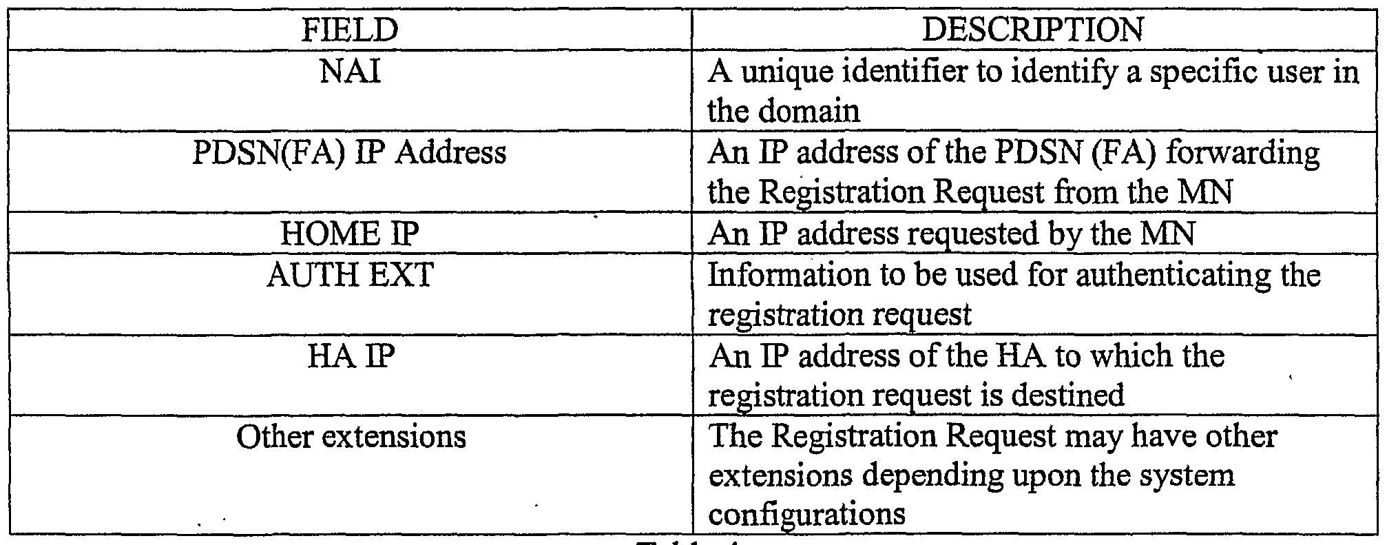
Figure 12 is a message sequence scenario 1200 illustrating a mobile D? registration process between the MN 202 and the HA 210 according to an exemplary embodiment. At step 1202, the MN 202 sends a Registration Request message to the PDSN 208. If the Registration Request message includes a network address of the HA 210, the PDSN 208 may send the Registration Request message directly to the HA 210. Alternatively, the PDSN 208 may query the FAAA 216 for a network address of a home agent associated with the MN 202. At step 1204, the PDSN 208 sends the Registration Request message to the HA 210. Table 4 illustrates exemplary fields that may be specified in a Registration Request message that is forwarded from the PDSN to the HA. However, it should be understood that different or fewer fields could also be present in Registration Request messages.
Tab e 4.
When the HA 210 receives the Registration Request message, and if the HA 210 and the
PDSN 208 share a mobility security association, the HA 210 may first check an authenticator in a Foreign-Home Authentication Extension in the received Registration Request message, based on the mobility security association. Then, at step 1206, the HA 210 may determine if current load(s) on the HA 210 are lower than the average system load(s) provided by the HACN 212 via heartbeat messages. According to an exemplary embodiment, the current load(s) on the HA 210 is lower than the average system load(s) and, thus, the HA 210 creates or updates an MBR for
the MN 202. Next, at step 1208, the HA 210 sends a Registration Reply message to the PDSN 208 that, then, sends the Registration Reply to the MN 202, as illustrated at 1210. Table 5 illustrates exemplary fields that may be specified in a Registration Reply message that is sent from the HA to the PDSN. However, it should be understood that different fields could also be specified.
Table 5.
Once the registration process is completed, at step 1212, the HA 210 also sends an MBR update message to the HACN 212 so that the HACN 212 has a copy of the session information.
At step 1214, the HACN 212 responds to the HA 210 with an MBR Acknowledgement message. Figure 13 is a message sequence scenario 1300 illustrating a MLP registration process between the MN 202 and the HA 210 according to one embodiment in which an average load on the HA 210 is higher than the average system load.
At step 1302, the MN 202 sends a Registration Request message to the PDSN 208. If the
Registration Request message includes a network address of the HA 210, the PDSN 208 may send the Registration Request message directly to the HA 210. Alternatively, the PDSN 208 may query the FAAA 216 for a network address of a home agent associated with the MN 202.
At step 1304, the PDSN 208 sends the Registration Request message to the HA 210.
When the HA 210 receives the Registration Request message, at step 1306, the HA 210 determines that its average load exceeds the average system load provided by the HACN 212.
Alternatively, in an embodiment in which certain groups of HAs are configured to serve predetermined communication session types, the HA 210 may determine that a communication session requested from the MN 202 is not one of the session types that are serviced at the HA 210. Upon making such a determination, at step 1308, the HA 210 selects the least loaded HA from one of the HA lists provided by the HACN 212. In an embodiment in which HAs are grouped based on the session types being served at the HAs, the HA 210 selects the least loaded HA that serves the session type being initiated from the MN 202.
At step 1310, the HA 210 forwards the Registration Request message to the selected HA, a HA 1320 in Figure 13. When the HA 520 receives the Registration Request message, the HA 1320 may process the registration request from the MN 202 and may respond to the PDSN 208 with a Registration Reply message, as shown at 1312. In such an embodiment, the HA 1320 updates a HA address field in the Registration Reply message to an address of the HA 1320. Alternatively, the HA 1320 may decline the Registration Request message and may go through a selection method as the HA 210 did. However, in such an approach, to avoid forwarding loops, when a Registration Request message is being forwarded from one HA to another, the Registration Request message may include a vendor specific attribute including an identifier indicating how many times the Registration Request message has been already forwarded. In such an embodiment, the identifier may have a format of one or more dirty bits, and may indicate, for instance, that the Registration Request message has been forwarded once and that the HA receiving the message should or must process the registration request. Alternatively, the registration request may additionally specify through which HAs the registration request has already passed so that a HA receiving the message does not select one of these HAs.
When the PDSN 208 receives the Registration Reply message, at step 1314, the PDSN 208 forwards the Registration Reply to the MN 202. Additionally, at step 1316, the HA 1320
sends an MBR Update message to the HACN 212 that responds with an MBR Update Acknowledgement message, as shown at step 1318.
Figure 14 is a message sequence scenario 1400 illustrating a registration process between the MN 202 and the HA 210 according to one embodiment, in which a load on the HA 210 is higher that the average system load, and in which the HA 210 is unable to determine another least loaded HA.
At step 1402, the MN 202 sends a Registration Request message to the PDSN 208. If the Registration Request message includes a network address of the HA 210, the PDSN 208 may send the Registration Request message directly to the HA 210. Alternatively, the PDSN 208 may query the FAAA 216 for a network address of a home agent associated with the MN 202. At step 1404, the PDSN 208 sends the Registration Request message to the HA 210.
When the HA 210 receives the Registration Request message, at step 1406, the HA 210 determines that its average load exceeds the average load on the system. Further, at step 1408, the HA 210 determines that it cannot make a decision on the least loaded HA to serve the Registration Request. In such an embodiment, as illustrated at step 1410 in Figure 14, the HA 210 forwards the Registration Request to the HACN 212 that then, at step 1412, selects the least loaded HA to serve the Registration Request from the MN 202. At step 1414, the HACN 212 forwards the Registration Request message to the selected HA, a HA 1450 in Figure 14. When the HA 1450 receives the Registration Request and accepts the Request, the HA 1450 sends a Registration Reply message including a network address of the HA 1450. Next, the HACN 212 forwards the Registration Reply message to the MN 202 via the PDSN 208, as illustrated at 1418 and 1420. Also, at step 1422, the HA 1450 sends an MBR Update message to the HACN 212 that responds with an MBR Update Acknowledgement message, as shown at 1424.
Figure 15 is a message sequence scenario 1500 illustrating a registration process between the MN 202 and the HA 210 according to one embodiment, in which a static MN EP address of the MN 202 does not belong to an address pool on the HA 210.
At step 1502, the MN 202 sends a Registration Request message to the PDSN 208 that may responsively communicate with a FAAA to authenticate the MN 202 and determine a HA of the MN 202, such as the HA 210. Next, the PD SN 208 forwards the Registration Request message to the HA 210, as shown at 1504. When the HA 210 receives the Registration Request message, at step 1506, the HA 210 determines that a static MN EP address of the MN 202 specified in the Registration Request message is not in a list of static MN EP address pool of the HA 210. Next, at step 1508, the HA 210 forwards the Registration Request message to the HACN 212 that, responsively to receiving the message, at step 1510, selects a HA, such as a HA 1550 illustrated in Figure 15, that serves the MN EP address specified in the Registration Request message.
At step 1512, the HACN 212 forwards the Registration Request message to the selected HA 1550 that sends a Registration Reply message to the MN 202 via the HACN 212 and the PDSN 208, as shown at 1514, 1516, and 1518. Additionally, at step 1520, the HA 1550 sends an MBR update message to theΗACN 212 that responds with an MBR Update Acknowledgement, as shown at 1522.
It should be understood that the programs, processes, methods and systems described herein are not related or limited to any particular type of computer or network system (hardware or software), unless indicated otherwise. Various types of general purpose or specialized computer systems supporting the EP networking may be used with or perform operations in accordance with the teachings described herein.
In view of the wide variety of embodiments to which the principles of the present invention can be applied, it should be understood that the illustrated embodiments are examples only, and should not be taken as limiting the scope of the present invention. For example, the steps of the flow diagrams may be taken in sequences other than those described, more or fewer steps may be used, and more or fewer elements may be used in the block diagrams. While various elements of the preferred embodiments have been described as being implemented in software, in other embodiments in hardware or firmware implementations may alternatively be used, and vice-versa.
The claims should not be read as limited to the described order or elements unless stated to that effect. Therefore, all embodiments that come within the scope and spirit of the following claims and equivalents thereto are claimed as the invention.