車両の衝突予防装置 技 術 分 野 Vehicle collision prevention device
本発明は、 先行車との車間距離が不十分となったときに警報又は 制動を行う車両の衝突予防装置に関する。 The present invention relates to a collision prevention device for a vehicle that issues a warning or a brake when an inter-vehicle distance from a preceding vehicle becomes insufficient.
明 この種の装置は、 例えば、 特開平技 6 — 2 3 1 4 0 0号公報に Akira This type of device is disclosed in, for example, Japanese Patent Application Laid-Open No. 6-231400.
書 book
されているよう に、 先行車の速度、 先行,術車の減速度、 自車の速度、 及び自車の最大減速度等に基づいて現時点における適正車間距離 ( この従来技術における適正車間距離は現時点での車間距離に対応し ているが、 以下に述べる本発明における適正車間距離は将来の予測 される車間距離に対応してお り 同従来技術とは異なっている) を求. め、 実際の車間距離が前記適正車間距離よ り小さい場合に警報を発 生するよう になっている。 また、 この装置は、 上記適正車間距離を 「先行車が所定の減速度で減速を開始した時点から遅れ時間 τ後に 自車が所定の減速度で減速した場合に衝突しない距離」 と定めてい る。 即ち、 先行車が減速を開始した後に自車が減速するとの仮定の 下で、 両車両が最も接近する際の車間距離が 「 0」 又はある程度の マ一ジン (マ一ジン距離) になると予測されるときに警報を発生す るようになっている。 As described above, the appropriate inter-vehicle distance at the present time (the appropriate inter-vehicle distance in this prior art is based on the speed of the preceding vehicle, the deceleration of the leading vehicle, the deceleration of the articulated vehicle, The appropriate inter-vehicle distance in the present invention described below corresponds to the predicted inter-vehicle distance in the future, which is different from the conventional technology.) When the inter-vehicle distance is smaller than the appropriate inter-vehicle distance, an alarm is issued. In addition, this device defines the appropriate inter-vehicle distance as "a distance at which the vehicle does not collide when the own vehicle decelerates at the predetermined deceleration after a delay time τ from the time when the preceding vehicle starts decelerating at the predetermined deceleration". . In other words, under the assumption that the own vehicle decelerates after the preceding vehicle starts decelerating, it is predicted that the inter-vehicle distance when both vehicles approach each other will be “0” or a certain margin (margin distance). When a warning is issued, a warning is issued.
しかしながら、 上記従来の装置においては、 最も接近したとさの 車間距離が 「 0」 又はある程度のマージン距離になると予測される ときに警報がなされるから、 同車間距離が 「 0」 又はある程度のマ 一ジン距離となる こ とを許容してお り 、 このような状態で先行車が 急減速する場合には車間距離が不足するという問題がある。 明 の 7 However, in the above-mentioned conventional apparatus, an alarm is issued when the inter-vehicle distance closest to the vehicle is predicted to be “0” or a certain margin distance, so that the inter-vehicle distance is “0” or a certain One gin distance is allowed, and if the preceding vehicle suddenly decelerates in such a state, there is a problem that the inter-vehicle distance becomes insufficient. Akira of 7
本発明の目的は、 自車が先行車に対して適切な車間距離を維持で
きるよう にするために、 よ り適切な時点で警報又は制動力を発生す る衝突予防装置を提供する こ とにあ り 、 その特徴の一つは、 衝突予 防装置が、 先行車の走行状態を検出する先行車走行状態検出手段と 、 自車の走行状態を検出する 自車走行状態検出手段と、 前記自車と 前記先行車との車間距離を検出する車間距離検出手段と、 前記検出 された先行車の走行状態、 前記検出された自車の走行状態、 及び前 記検出された車間距離に基づいて同自車と同先行車の最接近距離を 予測する最接近距離予測手段と、 前記先行車と前記自車との将来の 予測される車間距離に対応した適正車間距離を決定する適正車間距 離決定手段と、 前記予測された最接近距離が前記決定された適正車 間距離よ り小さい場合に警報又は制動力を発生する衝突予防手段と 、 を備えたことにある。 An object of the present invention is to enable a host vehicle to maintain an appropriate distance to a preceding vehicle One of the features is to provide a collision prevention device that generates an alarm or braking force at a more appropriate point in time. Preceding vehicle running state detecting means for detecting a state; own vehicle running state detecting means for detecting the running state of the own vehicle; inter-vehicle distance detecting means for detecting an inter-vehicle distance between the own vehicle and the preceding vehicle; Closest approach distance prediction means for estimating the closest approach distance between the own vehicle and the preceding vehicle based on the detected traveling state of the preceding vehicle, the detected traveling state of the own vehicle, and the detected inter-vehicle distance, An appropriate inter-vehicle distance determining means for determining an appropriate inter-vehicle distance corresponding to a predicted future inter-vehicle distance between the preceding vehicle and the own vehicle; and Generates an alarm or braking force when it is too small In further comprising a collision preventing means.
これによれば、 最接近距離予測手段によ り、 検出された先行車の 走行状態'、 検出された自車の走行状態、 及び検出された車間距離に 基づいて同自車と同先行車の最接近距離が予測され、 適正車間距離 決定手段によ り 、 前記先行車と前記自車との将来の予測される車間 距離に対応した適正車間距離が決定される。 そして、 衝突予防手段 によ り、 前記予測された最接近距離が前記決定された適正車間距離 よ り小さい場合に警報又は制動力が発生せしめ られる。 従って、 発 生される警報による運転者の制動操作による制動力、 又は自動的に 発生される制動力によ り 、 実際の最接近距離が適正車間距離に維持 され得る。 換言すると、 将来における実際の最接近距離が適正車間 距離以上となるよう に、 前もって警告又は制動力が発生される。 従 つて、 自車は先行車に最接近した時点において、 同先行車に対し適 切な車間距離を確保する ことができる。 この場合において、 前記適正車間距離決定手段は、 前記先行車と 前記自車の距離が前記最接近距離となる ときの同自車の速度を最接 近時速度として予測する とともに、 同予測された最接近時速度に基 づいて適正車間距離を決定するよう に構成される ことが好適である
これによれば、 例えば、 先行車の速度、 減速度等である検出され た先行車の走行状態、 例えば自車の速度等である 自車の走行状態、 及び検出された車間距離とから両車の最接近距離が予測される。 ま た、 自車が前車に最接近するときの自車の速度が予測され、 この予 測された最接近時の自車の速度 (最接近時速度) に基づいて適正車 間距離が決定される。 そして、 予測された最接近距離が、 決定され た適正車間距離よ り小さい場合に警報又は制動力が発生される。 According to this, based on the detected traveling state of the preceding vehicle, the detected traveling state of the own vehicle, and the detected inter-vehicle distance by the closest approach distance prediction means, the own vehicle and the preceding vehicle are determined. The closest approach distance is predicted, and an appropriate inter-vehicle distance corresponding to a predicted future inter-vehicle distance between the preceding vehicle and the own vehicle is determined by the appropriate inter-vehicle distance determining means. Then, when the predicted closest approach distance is smaller than the determined appropriate inter-vehicle distance, a warning or a braking force is generated by the collision prevention means. Therefore, the actual closest distance can be maintained at the appropriate inter-vehicle distance by the braking force generated by the driver's braking operation based on the generated alarm or the braking force automatically generated. In other words, a warning or braking force is generated in advance so that the actual closest approach distance in the future will be equal to or greater than the appropriate inter-vehicle distance. Therefore, when the own vehicle comes closest to the preceding vehicle, it can secure an appropriate inter-vehicle distance to the preceding vehicle. In this case, the appropriate inter-vehicle distance determination means predicts the speed of the own vehicle when the distance between the preceding vehicle and the own vehicle is the closest approach distance as the closest approach speed, and performs the same prediction. It is preferable to be configured to determine the appropriate inter-vehicle distance based on the speed at the time of closest approach. According to this, for example, based on the detected traveling state of the preceding vehicle such as the speed and deceleration of the preceding vehicle, the traveling state of the own vehicle such as the speed of the own vehicle, and the detected inter-vehicle distance, Is predicted. In addition, the speed of the own vehicle when the own vehicle comes closest to the preceding vehicle is predicted, and the appropriate inter-vehicle distance is determined based on the predicted speed of the own vehicle at the time of the closest approach (the speed at the time of the closest approach). Is done. Then, when the predicted closest approach distance is smaller than the determined appropriate inter-vehicle distance, an alarm or a braking force is generated.
最接近距離の予測において自車が先行車に最接近する のは、 同 自車と 同先行車と の速度が等し く なつ た時点 (即ち、 自車が 最接近時速度で走行する時点) であ り 、 かかる最接近時にお い て、 自車は先行車に対して同一の最接近時速度で追従走行する 状態 となる。 ま た、 一般に、 運転者は追従走行状態にお ける車 間距離をその と きの走行速度に応 じた距離だけ確保する。 従つ て、 上記構成の よ う に、 予測さ れる最接近時の車間距離が予測 される最接近時速度に基づいて決定された適正車間距離となる よ う に事前に警報又は制動力を発生すれば、 先行車の減速に伴 な う 自車の減速終了時 (即ち 、 最接近時) にお ける車間距離が 、 その時点の速度 (最接近時速度) に応 じた適切な車間距離 と な り 、 安全な車間距離が確保され得る。 こ の場合において、 前記適正車間距離決定手段は、 前記適正 車間距離を前記予測された最接近時速度 と予め設定された時間 の積に基づいて決定するよ う に構成される こ とが好適である。 In the prediction of the closest approach distance, the vehicle comes closest to the preceding vehicle when the speeds of the own vehicle and the preceding vehicle become equal (that is, when the vehicle runs at the speed at the time of the closest approach). However, at the time of the closest approach, the own vehicle follows the preceding vehicle at the same closest approach speed. In general, the driver secures the following distance in the following traveling state by a distance corresponding to the traveling speed at that time. Therefore, as described above, an alarm or a braking force is generated in advance so that the predicted inter-vehicle distance at the time of the closest approach becomes the appropriate inter-vehicle distance determined based on the predicted speed at the time of the closest approach. Then, at the end of deceleration of the own vehicle due to the deceleration of the preceding vehicle (that is, at the time of closest approach), the inter-vehicle distance becomes the appropriate inter-vehicle distance corresponding to the speed at that time (the speed at the time of closest approach) In other words, a safe inter-vehicle distance can be ensured. In this case, it is preferable that the appropriate inter-vehicle distance determining means is configured to determine the appropriate inter-vehicle distance based on a product of the predicted speed at the time of the closest approach and a preset time. is there.
前記予め設定された時間は、 本明細書において 「車頭時間」 と云 う時間とする こ とができ、 この車頭時間は自車が先行車の速度と略 等しい速度で同先行車に追従走行している場合に、 運転者が確保す る同先行車までの車間距離を自車の速度で除した値である。 実験に よる と、 この車頭時間は運転者が同一である限り 自車の速度が異な る場合でも大き く は変化しない。 従って、 車頭時間を運転者に応じ て選択し、 上記のよう に、 最接近時速度と車頭時間の積に基づいて 前記適正車間距離を決定すれば、 先行車の減速に伴なう警報に基づ
いた制動操作による制動力又は発生された制動力による自車の減速 後において、 同自車と同先行車の車間距離を各々 の運転者の感覚に 適合した安全な距離とする こ とが可能となる。 また、 前記予め定め られた時間が一定時間であっても、 上記特徴によ り、 前記自車の減 速後における同自車と先行車の車間距離を最接近時速度に応じた安 全な距離とする ことができる。 同様に、 前記適正車間距離決定手段は、 前記適正車間距離を前記 予測された最接近時速度と予め設定された時間の積に一定の余裕車 間距離を加えた値とするよう に構成される ことが好適である。 The preset time can be referred to as a “headway time” in the present specification, and the headway time is such that the own vehicle follows the preceding vehicle at a speed substantially equal to the speed of the preceding vehicle. In this case, the value obtained by dividing the inter-vehicle distance to the preceding vehicle secured by the driver by the speed of the own vehicle. According to experiments, this headway time does not change significantly even when the speed of the own vehicle is different as long as the driver is the same. Therefore, if the headway time is selected according to the driver, and the appropriate inter-vehicle distance is determined based on the product of the speed at the time of closest approach and the headway time, as described above, based on an alarm accompanying deceleration of the preceding vehicle, Zu It is possible to make the distance between the host vehicle and the preceding vehicle a safe distance that matches the driver's senses after the vehicle is decelerated by the braking force generated by the braking operation or the generated braking force. Become. Further, even if the predetermined time is a fixed time, according to the above-described features, the distance between the own vehicle and the preceding vehicle after the deceleration of the own vehicle can be safely determined according to the speed at the time of closest approach. It can be distance. Similarly, the appropriate inter-vehicle distance determining means is configured to set the appropriate inter-vehicle distance to a value obtained by adding a certain surplus inter-vehicle distance to the product of the predicted speed at the time of closest approach and a preset time. Is preferred.
これによれば、 前記予測された最接近時速度と予め設定され た時間の積に余裕車間距離を加え られた距離が適正時間 と され る ので、 例えば、 予測された最接近時速度が 「 0 」 となる状況 、 即ち 、 先行車が先に停止 し、 その後自車が停止する状況であ つ て も、 同先行車と同 自車 と の距離を同余裕車間距離だけ確保 できる ので、 同自車を安全に停止する こ とができる。 また、 このよ うな衝突予防装置は、 前記適正車間距離を確保する のに必要な目標減速度を演算する目標減速度演算手段を更に備える と と もに、 前記先行車走行状態検出手段は、 前記先行車の走行状態 と して同先行車の速度を検出する先行車速度検出手段と、 前記先行 車の走行状態と して同先行車の減速度を検出する先行車減速度検出 手段とを含み、 前記自車走行状態検出手段は、 前記自車の走行状態 と して同自車の速度を検出する自車速度検出手段と、 前記自車の走 行状態と して同自車の減速度を検出する 自車減速度検出手段とを含 み、 前記最接近距離予測手段は、 前記検出された先行車の速度、 前 記検出された先行車の減速度、 前記検出された自車の速度、 及び前 記検出された車間距離に基づいて最接近距離を予測するよう に構成 され、 前記衝突予防手段は、 前記予測された最接近距離が前記決定 された適正車間距離よ り小さ く なつた場合に前記検出される自車の 減速度が前記演算された目標減速度と等しく なるよう に制動力を発
生させる制動力発生手段を含むことが好適である。 According to this, the distance obtained by adding the surplus inter-vehicle distance to the product of the predicted speed at the time of the closest approach and the preset time is set as the appropriate time. In other words, even in a situation where the preceding vehicle stops first and then the own vehicle stops, the distance between the preceding vehicle and the own vehicle can be secured by the same inter-vehicle distance. You can safely stop the car. Further, such a collision prevention apparatus further includes a target deceleration calculating means for calculating a target deceleration required to secure the appropriate inter-vehicle distance, and the preceding vehicle traveling state detecting means includes: A preceding vehicle speed detecting means for detecting the speed of the preceding vehicle as the traveling state of the preceding vehicle; and a preceding vehicle deceleration detecting means for detecting the deceleration of the preceding vehicle as the traveling state of the preceding vehicle. The own vehicle running state detecting means includes: own vehicle speed detecting means for detecting the speed of the own vehicle as the running state of the own vehicle; and deceleration of the own vehicle as the running state of the own vehicle. The closest approach distance predicting means, wherein the detected closest vehicle speed, the detected preceding vehicle deceleration, and the detected own vehicle speed are included. The closest approach distance is predicted based on the detected inter-vehicle distance. And the collision prevention means is configured to calculate the detected deceleration of the own vehicle when the predicted closest approach distance becomes smaller than the determined appropriate inter-vehicle distance. Release braking force to be equal to deceleration It is preferable to include a braking force generating means for generating the braking force.
この場合において、 前記最接近距離予測手段は、 前記先行車が前 記先行車減速度検出手段によ り検出された減速度にて減速する とと もに前記自車が所定の空走時間だけ前記自車速度検出手段によ り検 出された速度で走行した後に所定の想定減速度にて減速する との仮 定の下で前記最接近距離を予測するよう に構成される ことが好適で ある。 In this case, the closest approach distance predicting means determines that the preceding vehicle decelerates at the deceleration detected by the preceding vehicle deceleration detecting means, and that the own vehicle has a predetermined idle running time. Preferably, the vehicle is configured to predict the closest approach distance on the assumption that the vehicle decelerates at a predetermined assumed deceleration after traveling at the speed detected by the vehicle speed detecting means. is there.
これによれば、 検出された先行車の速度、 検出された先行車の減 速度、 検出された自車の速度、 及び検出された車間距離に基づいて 最接近距離が予測され、 予測された最接近距離が適正車間距離よ り According to this, the closest approach distance is predicted based on the detected preceding vehicle speed, the detected preceding vehicle deceleration, the detected own vehicle speed, and the detected inter-vehicle distance. The approach distance is longer than the appropriate inter-vehicle distance
/ 'j、さ く なつた場合に制動力が発生される。 このとき、 前記適正車間 距離を確保するのに必要な目標減速度が目標減速度演算手段によ り 演算され、 前記制動力は、 この演算された目標減速度と検出された 減速度とが等しく なるよう に発生させられる。 この結果、 先行車が 走行している場合には適切な車間距離が確保される とともに、 先行 車が停止している場合には適正車間距離が確保された状態にて自車 が停止され得る。 この場合において、 前記目標減速度演算手段は、 車間距離が前記 車間距離検出手段の車間距離認知限度以下になったとき前記演算し た目標減速度を保持するよう に構成される ことが好適である。 / 'j, braking force is generated in the event of shortage. At this time, a target deceleration required to secure the appropriate inter-vehicle distance is calculated by target deceleration calculating means, and the braking force is equal to the calculated target deceleration and the detected deceleration. It is generated to be. As a result, when the preceding vehicle is running, an appropriate inter-vehicle distance is secured, and when the preceding vehicle is stopped, the own vehicle can be stopped with the appropriate inter-vehicle distance secured. In this case, it is preferable that the target deceleration calculating means is configured to hold the calculated target deceleration when the inter-vehicle distance becomes equal to or less than the inter-vehicle distance recognition limit of the inter-vehicle distance detecting means. .
これによれば、 車間距離が前記車間距離検出手段の車間距離認知 限度以下とな り、 実際には制動力を必要と しているにも拘らず、 制 動力の発生が停止されてしまう事態が回避される。 また、 前記目標減速度演算手段は、 前記制動力発生手段による制 動力発生後、 前記予測された最接近距離が前記決定された適正車間 距離よ り大きく なつた場合に前記先行車が走行中であるか否かを判 定し、 同先行車が走行中である と判定されたときは前記検出される 車間距離が所定の車間距離になるまで、 前記目標減速度を所定の減 速度に維持するよう に構成される こ とが好適である。
これによれば、 前記制動力発生手段による制動力発生後において 、 前記予測された最接近距離が前記決定された適正車間距離よ り大 きく なつた場合であっても、 前記先行車が走行中であれば、 所定の 減速度での減速が継続されるので、 所定の安全な車間距離が確保さ れる。 また、 前記所定の減速度を比較的小さい減速度とすれば、 減 速度を当初は大き く 、 次いで小さ くするよう に変化させ得るので、 好ましい減速が達成され得る。 更に、 前記目標減速度演算手段は、 演算される目標減速度が不安 定であるか否かを判定し、 前記演算される 目標減速度が不安定であ ると判定されるときに他の安定な値を前記目標減速度として設定す るように構成される ことが好適である。 According to this, the inter-vehicle distance becomes equal to or less than the inter-vehicle distance recognition limit of the inter-vehicle distance detection means, and the occurrence of braking force is stopped in spite of the fact that braking force is actually required. Be avoided. Further, the target deceleration calculating means is configured such that when the predicted closest approach distance becomes larger than the determined appropriate inter-vehicle distance after the braking force is generated by the braking force generating means, the preceding vehicle is running. The target deceleration is maintained at a predetermined deceleration until the detected inter-vehicle distance becomes a predetermined inter-vehicle distance. It is preferable to be configured as follows. According to this, after the braking force is generated by the braking force generation means, even if the predicted closest approach distance is larger than the determined appropriate inter-vehicle distance, the preceding vehicle is running. In this case, the deceleration at the predetermined deceleration is continued, so that a predetermined safe inter-vehicle distance is secured. Further, if the predetermined deceleration is a relatively small deceleration, the deceleration can be changed so as to be initially large and then reduced, so that a preferable deceleration can be achieved. Further, the target deceleration calculating means determines whether or not the calculated target deceleration is unstable. When it is determined that the calculated target deceleration is unstable, another stable deceleration is determined. It is preferable that an appropriate value be set as the target deceleration.
これによれば、 例えば、 小さな値で除する等の演算の結果、 得ら れる目標減速度が不安定であると判定される ときには、 他の安定な 値が前記目標減速度として設定されるので、 安定した制動力制御が 達成され得る。 なお、 この場合の他の安定な値とは、 前記最接近距 離予測手段が前記最接近距離を求める際に使用する自車の想定され た減速度 (想定減速度) である こ とが望ましい。 このよう にすれば 、 制動力を安定に計算でき、 精度の高い制動を実現できる。 また、 このような衝突予防装置は、 前記自車が停止したか否かを 判定する自車停止判定手段と、 前記予測された最接近距離が前記自 車の停止時に得られる場合に前記制動力発生手段によって前記制動 力が発生されたときは、 前記自車停止判定手段に つて自車が停止 したと判定されたときに制動力を所定の値に保持する停止時制動力 保持手段とを備える ことが好適である。 According to this, for example, when it is determined that the obtained target deceleration is unstable as a result of calculation such as division by a small value, another stable value is set as the target deceleration. Thus, stable braking force control can be achieved. The other stable value in this case is desirably the assumed deceleration (assumed deceleration) of the own vehicle used when the closest distance predicting means calculates the closest distance. . In this way, the braking force can be calculated stably, and highly accurate braking can be realized. Further, such a collision prevention device may further include: a vehicle stop determination unit configured to determine whether the vehicle has stopped; and a braking force when the predicted closest approach distance is obtained when the vehicle stops. When the braking force is generated by the generating means, a stopping-time braking force holding means for holding the braking force at a predetermined value when the own vehicle stop determination means determines that the own vehicle has stopped is provided. Is preferred.
前記予測された最接近距離が前記自車の停止時に得られる場合に 前記制動力発生手段によって前記制動力が発生されたときは、 同自 車を停止する ことが要求されているこ とを意味するが、 同自車が停 止したときには同制動力発生手段による制動力の発生も解除される 。 これに対し、 上記のよ う に構成すれば、 前記自車が停止したと判
定されたときに制動力が所定の値に保持され、 その結果、 自車を確 実に停止させておく ことができる。 また、 このよ う な衝突予防装置は、 前記自車のブレーキ装置が運 転者によって作動状態とされているか否かを判定するブレーキ作動 判定手段と、 前記ブレーキ装置が作動状態にあると判定されたとき に前記停止時制動力保持手段による制動力の保持を解除する制動力 保持解除手段とを備える ことが好適である。 この場合、 前記ブレー キ作動判定手段は、 ブレーキペダルの操作を検出するスィ ッチでも よく 、 或いは、 前記自車のブレーキマスタシリ ンダ油圧が所定油圧 以上か否かによ り前記ブレーキ装置が作動状態にあるか否かを判定 するように構成されてもよい。 When the predicted closest distance is obtained when the own vehicle stops, when the braking force is generated by the braking force generating means, it means that it is required to stop the own vehicle. However, when the vehicle stops, the generation of the braking force by the braking force generating means is also released. In contrast, with the above configuration, it is determined that the vehicle has stopped. When the braking force is set, the braking force is maintained at a predetermined value, and as a result, the own vehicle can be reliably stopped. In addition, such a collision prevention device includes: a brake operation determining unit that determines whether a brake device of the own vehicle is activated by a driver; and determines that the brake device is activated. It is preferable to include a braking force holding releasing means for releasing the holding of the braking force by the stopping-time braking force holding means when the stoppage occurs. In this case, the brake operation determining means may be a switch for detecting an operation of a brake pedal, or the brake device is operated based on whether or not the brake master cylinder oil pressure of the own vehicle is equal to or higher than a predetermined oil pressure. You may be comprised so that it may be determined whether it is in a state.
このよ う に構成するのは、 運転者によ り ブレーキ装置が作動状態 とされている場合、 もはや前記停止時制動力保持手段によって制動 力を保持する必要がないからである。 また、 このよ う な衝突予防装置は、 前記自車が停止したか否かを 判定する自車停止判定手段と前記予測された最接近距離が前記自車 の停止時に得られる場合に前記制動力発生手段によって前記制動力 が発生されたときは、 前記自車停止判定手段によって自車が停止し たと判定されたときに同自車のエンジンを停止させるエンジン停止 手段とを備える こ とが好適である。 The reason for this configuration is that when the brake device is activated by the driver, it is no longer necessary to hold the braking force by the stopping-time braking force holding means. In addition, such a collision prevention device includes: a self-vehicle stop determination unit that determines whether the self-vehicle is stopped; and the braking force when the predicted closest approach distance is obtained when the self-vehicle is stopped. When the braking force is generated by the generation means, it is preferable to include an engine stop means for stopping the engine of the own vehicle when the own vehicle stop determination means determines that the own vehicle has stopped. is there.
これによれば、 前記予測された最接近距離が前記'自車の停止時に 得られる場合、 前記制動力発生手段によって前記制動力が発生され て自車が停止され、 その後エンジンが停止されるので、 同自車を確 実に停止状態に維持する ことができる。 本発明の他の特徴は、 予防衝突装置が、 先行車の走行状態を検出 する先行車走行状態検出手段と、 自車の走行状態を検出する 自車走 行状態検出手段と、 前記自車と前記先行車との車間距離を検出する 車間距離検出手段と、 前記検出された先行車の走行状態、 前記検出
された自車の走行状態、 前記検出された車間距離、 及び自車の想定 された想定減速度に基づいて同自車と同先行車との最接近距離を予 測する最接近距離予測手段と、 前記予測された最接近距離が所定の 適正車間距離よ り小さい場合に警報又は制動力を発生する衝突予防 手段とを備えた車両の衝突予防装置であって、 前記最接近距離予測 手段は、 前記想定減速度を前記自車が走行する路面の路面摩擦係数 から定まる最大減速度よ り小さい減速度として前記最接近距離を予 測するよう に構成されたことにある。 According to this, when the predicted closest approach distance is obtained at the time of stopping the own vehicle, the braking force is generated by the braking force generating means, the own vehicle is stopped, and then the engine is stopped. Therefore, the own vehicle can be reliably maintained in a stopped state. Another feature of the present invention is that the preventive collision device detects a traveling state of a preceding vehicle, detects a traveling state of a preceding vehicle, detects a traveling state of the vehicle, and detects a traveling state of the vehicle. An inter-vehicle distance detecting means for detecting an inter-vehicle distance with the preceding vehicle; a detected traveling state of the preceding vehicle; Closest approach distance prediction means for estimating the closest approach distance between the own vehicle and the preceding vehicle based on the detected traveling state of the own vehicle, the detected inter-vehicle distance, and the assumed deceleration of the own vehicle; and A collision prevention device that generates an alarm or a braking force when the predicted closest distance is smaller than a predetermined appropriate inter-vehicle distance, wherein the closest distance prediction device includes: It is configured that the closest approach distance is predicted by setting the assumed deceleration as a deceleration smaller than a maximum deceleration determined from a road surface friction coefficient of a road surface on which the vehicle travels.
これによれば、 検出された先行車の速度、 減速度等の走行状態、 検出された自車の速度等の走行状態、 検出された車間距離、 及び自 車の想定された想定減速度に基づいて同自車と同先行車との最接近 距離が予測され、 予測された最接近距離が所定の適正車間距離よ り 小さい場合に警報又は制動力が発生される。 また、 前記最接近距離 は、 自車が走行している路面の路面摩擦係数によ り定まる最大減速 度 (自車が発生し得る最大減速度) よ り小さい減速度 (想定減速度 ) で減速するものと して予測される。 従って、 先行車がさ らに大き な減速度にて減速を開始した場合であっても、 自車には同自車の減 速度を増大する余地が残されているので、 例えば運転者は自車の減 速度を増大する ことができる。 この場合、 前記最接近距離予測手段は、 前記自車が走行する路面 の路面摩擦係数と重力加速度との積に 1 よ り小さい係数を乗じた値 を前記自車の想定減速度とするよう に構成される ことが好適である これによれば、 走行路面において得られる最大減速度よ り も小さ い想定減速度を簡易かつ確実に得る ことができる。 本発明の他の特徴は、 衝突予防装置が、 先行車の速度を検出する 先行車速度検出手段と、 前記先行車の減速度を検出する先行車減速 度検出手段と、 自車の速度を検出する自車速度検出手段と、 前記自 車と前記先行車との車間距離を検出する車間距離検出手段と、 前記
先行車が前記検出された先行車の減速度で減速する とともに前記自 車が所定の空走時間だけ前記検出された自車の速度で走行した後に 所定の想定減速度で減速する との仮定の下で、 前記検出された先行 車の速度、 前記検出された先行車の減速度、 前記検出された自車の 速度、 及び前記検出された車間距離に基づいて前記自車と前記先行 車の第 1 の最接近距離を予測する第 1 最接近距離予測手段と、 前記 第 1 最接近距離予測手段の仮定下で前記自車が前記先行車に最接近 するまでの時点において前記先行車が路面摩擦係数から推定される 最大減速度での減速を開始する とともに所定の時間後に前記自車が 同最大減速度での減速を開始するものと仮定して、 前記検出された 先行車の速度、 前記検出された先行車の減速度、 前記検出された自 車の速度、 及び前記検出された車間距離に基づいて第 2 の最接近距 離を予測する第 2最接近距離予測手段と、 前記予測された第 1 の最 接近距離が第 1 適正車間距離よ り小さいか、 または前記予測された 第 2 の最接近距離が第 2適正車間距離よ り 小さいと判定された場合 に警報又は制動力を発生する衝突予防手段とを備えたことにある。 According to this, based on the detected traveling state such as the speed of the preceding vehicle and the deceleration, the detected traveling state such as the speed of the own vehicle, the detected inter-vehicle distance, and the assumed deceleration of the own vehicle. Accordingly, the closest approach distance between the own vehicle and the preceding vehicle is predicted, and if the predicted closest approach distance is smaller than a predetermined appropriate inter-vehicle distance, an alarm or a braking force is generated. The closest approach distance is reduced at a deceleration (estimated deceleration) smaller than the maximum deceleration (maximum deceleration that can be generated by the vehicle) determined by the road surface friction coefficient of the road on which the vehicle is running. Expected to do so. Therefore, even if the preceding vehicle starts to decelerate at a larger deceleration, the driver's own vehicle still has room to increase the deceleration of the driver's own vehicle. The deceleration of the car can be increased. In this case, the closest approach distance predicting means may set a value obtained by multiplying a product of a road surface friction coefficient of the road surface on which the vehicle runs and a gravitational acceleration by a coefficient smaller than 1 as the assumed deceleration of the vehicle. According to this, it is possible to easily and reliably obtain an assumed deceleration smaller than the maximum deceleration obtained on the traveling road surface. Another feature of the present invention is that the collision prevention device includes: preceding vehicle speed detecting means for detecting the speed of the preceding vehicle; preceding vehicle deceleration detecting means for detecting the deceleration of the preceding vehicle; and detecting the speed of the own vehicle. Own vehicle speed detecting means, inter-vehicle distance detecting means for detecting an inter-vehicle distance between the own vehicle and the preceding vehicle, It is assumed that the preceding vehicle decelerates at the detected deceleration of the preceding vehicle, and that the own vehicle travels at the detected own vehicle speed for the predetermined idle running time and then decelerates at the predetermined assumed deceleration. Below, based on the detected speed of the preceding vehicle, the detected deceleration of the preceding vehicle, the detected speed of the own vehicle, and the detected inter-vehicle distance, (1) first closest approach distance predicting means for predicting the closest approach distance, and the preceding vehicle is subject to road surface friction at the time when the own vehicle approaches the preceding vehicle under the assumption of the first closest approach distance predicting means. Starting the deceleration at the maximum deceleration estimated from the coefficient, and assuming that the own vehicle starts decelerating at the same maximum deceleration after a predetermined time, the detected speed of the preceding vehicle and the detection Detected preceding vehicle deceleration, detection Second closest approach distance predicting means for predicting a second closest approach distance based on the detected speed of the own vehicle and the detected inter-vehicle distance, and the predicted first closest approach distance is a first appropriate distance. Collision prevention means for generating an alarm or a braking force when it is determined that the distance is smaller than the inter-vehicle distance or the predicted second closest distance is smaller than the second appropriate inter-vehicle distance. .
これによれば、 第 1 最接近距離予測手段によ り 、 前記先行車が前 記検出された先行車の減速度で減速すると ともに前記自車が所定の 空走時間だけ前記検出された自車の速度で走行した後に所定の想定 減速度で減速する との仮定の下で、 前記検出された先行車の速度、 前記検出された先行車の減速度、 前記検出された自車の速度、 及び 前記検出された車間距離に基づいて同自車と同先行車の第 1 の最接 近距離が予測される。 According to this, by the first closest approach distance prediction means, the preceding vehicle is decelerated at the deceleration of the preceding vehicle detected as described above, and the own vehicle is detected for the predetermined idle running time. Under the assumption that the vehicle decelerates at a predetermined assumed deceleration after traveling at the speed of, the detected speed of the preceding vehicle, the detected deceleration of the preceding vehicle, the detected speed of the own vehicle, and The first closest distance between the own vehicle and the preceding vehicle is predicted based on the detected inter-vehicle distance.
また、 第 2最接近距離予測手段によ り、 前記第 1 最接近距離予測 手段の仮定下で前記自車が前記先行車に最接近するまでの時点にお いて前記先行車が路面摩擦係数から定まる最大減速度での減速を開 始する とともに所定の時間後に前記自車が同最大減速度での減速を 開始するものと仮定して、 前記検出された先行車の速度、 前記検出 された先行車の減速度、 前記検出された自車の速度、 及び前記検出 された車間距離に基づいて第 2 の最接近距離が予測される。 Further, the second closest approach distance predicting means calculates the preceding vehicle from the road surface friction coefficient until the own vehicle approaches the preceding vehicle under the assumption of the first closest approach distance predicting means. Assuming that the vehicle starts deceleration at the determined maximum deceleration and that the own vehicle starts deceleration at the same maximum deceleration after a predetermined time, the detected speed of the preceding vehicle and the detected preceding A second closest approach distance is predicted based on the deceleration of the vehicle, the detected speed of the own vehicle, and the detected inter-vehicle distance.
そして、 衝突防止手段によ り、 前記予測された第 1 の最接近距離
が第 1 適正車間距離よ り小さいか、 または前記予測された第 2 の最 接近距離が第 2適正車間距離よ り小さいと判定された場合に警報又 は制動力が発生される。 従って、 先行車が当初に検出された減速度 よ り も大きな減速度で減速を開始する こ とに備えた適切なタイ ミ ン グで警報又は制動力が発生されるので、 自車が先行車に極めて接近 する事態が未然に回避され得る。 なお、 前記第 2適正車間距離は前 記第 1 適正車間距離以下である ことが好まし く 、 例えば、 同第 2適 正車間距離は停止時に先行車との間に確保すべき余裕車間距離とよ ばれる距離とすると良い。 本発明の他の特徴は、 衝突予防装置が、 先行車の走行状態を 検出する先行車走行状態検出手段 と 、 自車の走行状態を検出す る 自車走行状態検出手段 と、 前記 自車 と前記先行車と の車間距 離を検出する車間距離検出手段 と、 前記検出さ れた先行車の走 行状態、 前記検出 された 自車の走行状態、 前記検出された車間 距離、 及び前記 自車の想定された想定減速度に基づいて同 自車 と 同先行車 と の最接近距離を予測する最接近距離予測手段 と、 前記予測さ れた最接近距離が所定の適正車間距離よ り 小さ い場 合に警報又は制動力 を発生する と と も に、 前記車間距離検出手 段によ り検出さ れた実際の車間距離が所定の距離よ り 小さ い と き に警報又は制動力 を発生する衝突予防手段と を備えた こ と に あ る。 更に、 こ の場合において、 前記 自車走行状態検出手段は 少な く と も 同 自車の速度を検出 し、 前記衝突予防手段は前記所 定の距離を前記検出された 自車の速度 と予め設定された所定の 時間の積に所定の余裕車間距離を加えた値 とする よ う に構成さ れる こ とが好適である。 And the anticipated first closest approach distance by the collision prevention means. Is determined to be smaller than the first appropriate inter-vehicle distance or the predicted second closest approach distance is smaller than the second appropriate inter-vehicle distance, an alarm or a braking force is generated. Therefore, an alarm or braking force is generated at an appropriate timing in preparation for the preceding vehicle to start decelerating at a deceleration greater than the initially detected deceleration. It is possible to avoid a situation in which a person is extremely close to a vehicle. It is preferable that the second appropriate inter-vehicle distance is equal to or less than the first appropriate inter-vehicle distance. It is good to be called distance. Another feature of the present invention is that the collision prevention device includes: a preceding vehicle traveling state detecting unit that detects a traveling state of a preceding vehicle; an own vehicle traveling state detecting unit that detects a traveling state of the own vehicle; An inter-vehicle distance detecting means for detecting an inter-vehicle distance from the preceding vehicle; a detected traveling state of the preceding vehicle, the detected traveling state of the own vehicle, the detected inter-vehicle distance, and the own vehicle. Closest approach distance predicting means for estimating the closest approach distance between the own vehicle and the preceding vehicle based on the assumed deceleration of the vehicle; and the estimated closest approach distance is smaller than a predetermined appropriate inter-vehicle distance. In this case, an alarm or a braking force is generated, and an alarm or a braking force is generated when the actual inter-vehicle distance detected by the inter-vehicle distance detection means is smaller than a predetermined distance. And means for preventing collision. Further, in this case, the own-vehicle traveling state detecting means detects at least the speed of the own-vehicle, and the collision preventing means sets the predetermined distance to the detected own-vehicle speed in advance. It is preferable that a value obtained by adding a predetermined extra inter-vehicle distance to a product of the obtained predetermined time is used.
これによれば、 検出された先行車の速度、 減速度等の走行状態、 前記検出された自車の速度等の走行状態、 前記検出された車間距離 、 及び自車の想定された想定減速度に基づいて同自車と同先行車と の最接近距離が予測され、 この予測された最接近距離が所定の適正 車間距離よ り小さい場合に警報又は制動力が発生される。 また、 予
測された最接近距離が所定の適正車間距離よ り小さ く ない場合であ つても、 前記車間距離検出手段によ り検出された実際の車間距離が 所定の距離 (例えば、 前記検出された自車の速度と予め設定された 所定の時間の積に所定の余裕車間距離を加えた距離) よ り 小さいと きに警報又は制動力が発生される。 従って、 後方か ら自車を追い越 した車両などが車線変更によ り 自車の直前に割込んできたような場 合であっても、 警報又は制動力が発生されるので、 安全な車間距離 が維持され得る。 本発明の他の特徴は、 衝突予防装置が、 先行車の走行状態を検出 する先行車走行状態検出手段と、 自車の走行状態を検出する 自車走 行状態検出手段と、 前記自車と前記先行車との車間距離を検出する 車間距離検出手段と、 前記検出された先行車の走行状態、 前記検出 された自車の走行状態、 前記検出された車間距離、 及び前記自車の 想定された想定減速度に基づいて同自車と同先行車との最接近距離 を予測する最接近距離予測手段と、 前記先行車と前記自車の距離が 前記最接近距離となる ときの同自車の速度を最接近時速度と して予 測する とと もに、 同予測された最接近時速度に基づいて適正車間距 離を決定する適正車間距離決定手段と、 前記予測された最接近距離 が前記適正車間距離決定手段によ り決定される適正車間距離よ り小 さい場合に警報又は制動力を発生し、 同警報又は同制動力の発生後 に前記予測される最接近距離が前記適正車間距離決定手段によ り決 定される適正距離よ り も所定距離だけ大きく なつたとき同警報又は 同制動力の発生を停止する衝突予防手段とを備えたことにある。 According to this, the detected traveling state such as the speed of the preceding vehicle and the deceleration, the detected traveling state such as the speed of the own vehicle, the detected inter-vehicle distance, and the assumed deceleration of the own vehicle The closest approach distance between the own vehicle and the preceding vehicle is predicted on the basis of the distance. If the predicted closest approach distance is smaller than a predetermined appropriate inter-vehicle distance, an alarm or a braking force is generated. Also, Even when the measured closest approach distance is not smaller than a predetermined appropriate inter-vehicle distance, the actual inter-vehicle distance detected by the inter-vehicle distance detection means is equal to or less than a predetermined distance (for example, the detected self-interval distance). When the vehicle speed is smaller than the product of the speed of the vehicle and a predetermined time set in advance plus a predetermined allowance, a warning or braking force is generated. Therefore, even if a vehicle that overtakes the vehicle from behind is interrupted immediately before the vehicle due to a lane change, an alarm or braking force is generated, and a safe Distance can be maintained. Another feature of the present invention is that the collision prevention device includes: a preceding vehicle traveling state detecting unit that detects a traveling state of a preceding vehicle; an own vehicle running state detecting unit that detects a traveling state of the own vehicle; An inter-vehicle distance detecting means for detecting an inter-vehicle distance with the preceding vehicle; a detected traveling state of the preceding vehicle, the detected traveling state of the own vehicle, the detected inter-vehicle distance, and an assumption of the own vehicle. Closest approach distance prediction means for estimating the closest approach distance between the own vehicle and the preceding vehicle based on the assumed deceleration, and the own vehicle when the distance between the preceding vehicle and the own vehicle is the closest approach distance. A suitable inter-vehicle distance determining means for predicting the speed of the vehicle as a speed at the time of closest approach, and determining an appropriate inter-vehicle distance based on the predicted speed at the time of closest approach; and Is the appropriate headway determined by the appropriate headway distance determining means. An alarm or braking force is generated when the vehicle is separated from the vehicle, and after the alarm or braking force is generated, the predicted closest approach distance is longer than the appropriate distance determined by the appropriate inter-vehicle distance determining means. The vehicle also has a collision prevention means for stopping the generation of the warning or the braking force when the distance has increased by a predetermined distance.
これによれば、 検出された先行車の速度、 減速度等の走行状態、 前記検出された自車の速度等の走行状態、 前記検出された車間距離 、 及び自車の想定された想定減速度に基づいて同自車と同先行車と の最接近距離が予測される。 また、 自車が前車に最接近する ときの 自車の速度が予測され、 この予測された最接近時の自車の速度 (最 接近時速度) に基づいて適正車間距離が決定される。 そして、 予測 された最接近距離が決定された適正車間距離よ り小さい場合に警報
又は制動力が発生される。 また、 前記警報又は前記制動力の発生後 に前記予測される最接近距離が前記適正車間距離決定手段によって 決定される適正車間距離よ り も所定距離だけ大きく なつたとき同警 報又は同制動力の発生が停止される。 従って、 警報又は制動力の発 生の停止直後に再び同警報又は同制動力が発生され難く なるので、 頻繁な警報又は制動力の発生を回避する ことができる。 本発明の他の特徴は、 衝突予防装置が、 先行車の速度を検出する 先行車速度検出手段と、 前記先行車の減速度を検出する先行車減速 度検出手段と、 自車の速度を検出する自車速度検出手段と、 前記自 車と前記先行車との車間距離を検出する車間距離検出手段と、 前記 先行車が前記検出された減速度で減速する とともに前記自車が第 1 空走時間だけ前記検出された速度で走行した後に第 1 想定減速度で 減速するとの仮定の下で、 同自車と同先行車との第 1 最接近距離と 第 1 最接近時速度とを予測し、 同予測された第 1 最接近距離が同予 測された第 1 最接近時速度と予め設定された第 1 時間の積に基づい て決定される第 1 適正車間距離よ り も小さいときに警報又は制動力 を発生する第 1 衝突予防手段と、 前記先行車が前記検出された減速 度で減速すると ともに前記自車が前記第 1 空走時間以下の第 2 空走 時間だけ前記検出された速度で走行した後に前記第 1 想定減速度以 上の第 2想定減速度で減速する との仮定の下で、 同自車と同先行車 との第 2最接近距離と第 2最接近時速度とを予測し、 同予測された 第 2最接近距離が同予測された第 2最接近時速度と予め設定された 前記第 1 時間以下の第 2時間の積に基づいて決定される第 2適正車 間距離よ り も小さいときに警報又は制動力を発生する第 2衝突予防 手段と、 前記第 2衝突予防手段によ り前記警報又は前記制動力が発 生されたときは、 前記第 1 衝突予防手段によって前記警報又は前記 制動力が発生されない状態となるまで、 同第 2衝突予防手段による 同警報又は同制動力の発生を継続する予防措置継続手段とを備えた ことにある。 According to this, the detected traveling state such as the speed of the preceding vehicle and the deceleration, the detected traveling state such as the speed of the own vehicle, the detected inter-vehicle distance, and the assumed deceleration of the own vehicle The closest approach distance between the own vehicle and the preceding vehicle is predicted based on the distance. Further, the speed of the own vehicle when the own vehicle comes closest to the preceding vehicle is predicted, and the appropriate inter-vehicle distance is determined based on the predicted speed of the own vehicle at the time of the closest approach (the speed at the time of the closest approach). If the predicted closest approach distance is smaller than the determined appropriate inter-vehicle distance, an alarm is issued. Alternatively, a braking force is generated. Further, when the predicted closest approach distance after the generation of the alarm or the braking force becomes larger by a predetermined distance than the appropriate inter-vehicle distance determined by the appropriate inter-vehicle distance determining means, the alarm or the braking force is applied. Is stopped. Therefore, it is difficult to generate the alarm or the braking force again immediately after the generation of the alarm or the braking force is stopped, so that the frequent generation of the alarm or the braking force can be avoided. Another feature of the present invention is that the collision prevention device includes: preceding vehicle speed detecting means for detecting the speed of the preceding vehicle; preceding vehicle deceleration detecting means for detecting the deceleration of the preceding vehicle; and detecting the speed of the own vehicle. Own vehicle speed detecting means, inter-vehicle distance detecting means for detecting an inter-vehicle distance between the own vehicle and the preceding vehicle, and the preceding vehicle decelerates at the detected deceleration, and the own vehicle runs in the first idle state. Under the assumption that the vehicle travels at the detected speed for the time described above and then decelerates at the first assumed deceleration, the first closest approach distance and the first closest approach speed between the own vehicle and the preceding vehicle are predicted. An alarm is issued when the predicted first closest approach distance is smaller than a first appropriate inter-vehicle distance determined based on a product of the predicted first closest approach speed and a preset first time. Or first collision prevention means for generating a braking force; and After the vehicle decelerates at the deceleration rate, the own vehicle travels at the detected speed for the second idle time that is equal to or less than the first idle time, and then decelerates at the second assumed deceleration that is equal to or greater than the first assumed deceleration. The second closest approach distance and the speed at the time of the second closest approach between the own vehicle and the preceding vehicle are predicted based on the assumption that the second closest approach distance is the second closest approach distance. A second collision prevention means for generating an alarm or a braking force when the distance is smaller than a second appropriate inter-vehicle distance determined based on a product of the approach time and a predetermined second time equal to or shorter than the first time; and When the warning or the braking force is generated by the second collision prevention means, the second collision prevention is performed until the warning or the braking force is not generated by the first collision prevention means. Precautionary measures continuation means to continue the generation of the alarm or the braking force by means It is in preparation.
これによれば、 第 1 衝突予防手段によ り 、 前記先行車が前記検出
された減速度で減速する とともに前記自車が第 1 空走時間だけ前記 検出された速度で走行した後に第 1 想定減速度で減速する との仮定 の下で、 同自車と同先行車との第 1 最接近距離と第 1 最接近時速度 とを予測し、 同予測された第 1 最接近距離が同予測された第 1 最接 近時速度と予め設定された第 1 時間との積に基づいて決定される第 1 適正車間距離よ り も小さいときに警報又は制動力が発生される。 また、 第 2衝突予防手段によ り 、 前記先行車が前記検出された減 速度で減速する とともに前記自車が前記第 1 空走時間以下の第 2空 走時間だけ前記検出された速度で走行した後に前記第 1想定時間以 上の第 2 想定減速度で減速する との仮定の下で、 同自車と同先行車 との第 2 最接近距離と第 2最接近時速度とを予測し、 同予測された 第 2最接近距離が同予測された第 2最接近時速度と予め設定された 前記第 1 時間以下の第 2 時間の積に基づいて決定される第 2適正車 間距離よ り も小さいときに警報又は制動力が発生される。 この結果 、 第 2衝突予防手段は第 1 衝突予防手段よ り も遅いタイ ミ ングで警 報又は制動力を発生する。 According to this, the preceding vehicle detects the preceding vehicle by the first collision prevention means. Under the assumption that the vehicle decelerates at the detected deceleration and the vehicle decelerates at the first assumed deceleration after the vehicle travels at the detected speed for the first idle running time. Of the first closest approach distance and the speed at the time of the first closest approach, and the predicted first closest approach distance is the product of the predicted first closest approach speed and the first time set in advance. An alarm or braking force is generated when the distance is smaller than the first appropriate inter-vehicle distance determined based on the vehicle. In addition, the second collision prevention means causes the preceding vehicle to decelerate at the detected deceleration and the own vehicle travels at the detected speed for a second idle time that is equal to or less than the first idle time. Then, under the assumption that the vehicle decelerates at the second assumed deceleration longer than the first assumed time, the second closest approach distance and the second closest approach speed between the own vehicle and the preceding vehicle are predicted. The predicted second closest approach distance is a second appropriate inter-vehicle distance determined based on a product of the predicted second closest approach speed and a preset second time equal to or shorter than the first time. Alarm or a braking force is generated when the magnitude is smaller. As a result, the second collision prevention means generates a warning or a braking force at a later timing than the first collision prevention means.
そして、 予防措置継続手段によ り 、 前記第 2衝突予防手段による 前記警報又は前記制動力の発生は、 前記第 1 衝突予防手段によって 前記警報又は前記制動力が発生されない状態となるまで継続される 。 第 1 衝突予防手段は、 第 2衝突予防手段よ り も早いタイ ミ ングで 警報又は制動力を発生するから、 同第 1 衝突予防手段によって警報 又は制動力が発生されない状態となった時点では、 車間距離が十分 安全な距離以上に確保されている。 従って、 そのような状態となる まで第 2 衝突予防手段による警報又は制動力の発生を継続するよう にしたものである。 この場合において、 前記自車のブレーキ装置が運転者によって作 動状態とされているか否かを判定するブレーキ作動判定手段を備え 、 前記第 1 衝突予防手段は前記ブレーキ作動判定手段によ り前記ブ レーキが作動状態にないと判定されたときは同ブレーキが作動状態 にある と判定された場合よ り 、 前記第 1 空走時間を長い時間に変更
して前記第 1 最接近距離を予測するよ う に構成され、 前記予防措置 継続手段は前記第 1 衝突予防手段が前記長い時間に変更された第 1 空走時間に基づいて前記第 1 最接近距離を予測した場合でも前記警 報又は前記制動力を発生しない状態となるまで前記第 2衝突予防手 段による前記警報又は前記制動力の発生を継続するよう に構成され ることが好適である。 The generation of the warning or the braking force by the second collision prevention means is continued by the preventive measure continuation means until the warning or the braking force is not generated by the first collision prevention means. . Since the first collision prevention means generates an alarm or braking force at a timing earlier than the second collision prevention means, when the first collision prevention means does not generate an alarm or braking force, The inter-vehicle distance is sufficiently longer than the safe distance. Therefore, the warning or the braking force is continuously generated by the second collision prevention means until such a state is reached. In this case, there is provided a brake operation determining means for determining whether or not the brake device of the own vehicle is activated by a driver, and the first collision prevention means is provided with the brake operation determining means by the brake operation determining means. When it is determined that the rake is not in operation, the first idle running time is changed to a longer time than when it is determined that the brake is in operation. And the first closest approach distance is predicted, and the preventive measure continuation means is configured to execute the first closest approach based on the first idle running time changed by the first collision prevention means to the long time. It is preferable that the warning or the braking force is continuously generated by the second collision prevention means until the warning or the braking force is not generated even when the distance is predicted.
これによれば、 ブレーキが非作動状態にある場合には、 例えばァ クセルペダルからブレーキペダルへの踏み換え時間に相当するだけ 、 同ブレーキが作動状態にある場合よ り も第 1 空走時間が延長され 、 その延長された第 1 空走時間にて第 1 最接近距離が予測されて、 警報又は制動力の発生の必要性が判断される。 また、 予防措置継続 手段によ り、 前記第 2衝突予防手段による前記警報又は前記制動力 の発生は、 前記第 1 衝突予防手段によって前記延長された第 1 空走 時間に基づいて前記第 1最接近距離を予測した場合でも前記警報又 は前記制動力を発生しない状態となるまで継続される。 According to this, when the brake is in the non-operation state, the first idle running time is longer than in the case where the brake is in the operation state, for example, by the time corresponding to the step change time from the accelerator pedal to the brake pedal. Then, the first closest approach distance is predicted based on the extended first idle running time, and the necessity of generating a warning or a braking force is determined. Further, according to the preventive measure continuation means, the generation of the alarm or the braking force by the second collision prevention means is based on the first idle running time extended by the first collision prevention means. Even when the approach distance is predicted, the process is continued until the warning or the braking force is not generated.
第 1 衝突予防手段による警報又は制動力は、 第 2衝突予防手段よ り も早期に発生される。 また、 第 1 衝突予防手段は、 空走時間が延 長されるブレーキが非作動状態にある場合の方が、 ブレーキが作動 状態にある場合よ り も、 一層早期に警報又は制動力を発生する。 従 つて、 ブレーキが非作動状態にあるときに第 1 衝突予防手段が警報 又は制動力を発生しない状態では、 車間距離がよ り安全な距離以上 に確保されているので、 その時点にて第 2衝突予防手段による警報 又は制動力の発生を停止するようにしたものである。 本発明の他の特徴は、 衝突予防装置が、 先行車の速度を検出する 先行車速度検出手段と、 先行車の減速度を検出する先行車減速度検 出手段と、 自車の速度を検出する 自車速度検出手段と、 前記自車と 前記先行車との車間距離を検出する車間距離検出手段と、 前記自車 のブレーキ装置が運転者によって作動状態とされているか否かを判 定するブレーキ作動判定手段を備え、 前記先行車が前記検出された 減速度で減速する とともに前記自車が所定の空走時間だけ前記検出
された速度で走行した後に所定の想定減速度で減速するとの仮定の 下で、 前記検出された先行車の速度、 前記検出された先行車の減速 度、 前記検出された自車の速度、 及び前記検出された車間距離に基 づいて同自車と同先行車との最接近距離を予測し、 同予測された最 接近距離が所定の適正車間距離よ り も小さいときに警報又は制動力 を発生する衝突予防手段と、 前記ブレーキ作動判定手段によ り ブレ 一キが作動状態にないと判定されたときは同ブレーキが作動状態に あると判定された場合よ り 、 前記所定の空走時間を長い時間に変更 する空走時間変更手段とを備えたことにある。 The warning or braking force by the first collision prevention means is generated earlier than the second collision prevention means. In addition, the first collision prevention means generates an alarm or a braking force earlier when the brake for which the idling time is extended is inactive than when the brake is in operation. . Therefore, if the first collision prevention means does not generate an alarm or braking force when the brake is inactive, the following distance is secured more than a safer distance. The warning or the braking force generated by the collision prevention means is stopped. Another feature of the present invention is that the collision prevention device comprises: a preceding vehicle speed detecting means for detecting the speed of the preceding vehicle; a preceding vehicle deceleration detecting means for detecting the deceleration of the preceding vehicle; and detecting the speed of the own vehicle. Vehicle speed detecting means, inter-vehicle distance detecting means for detecting an inter-vehicle distance between the own vehicle and the preceding vehicle, and determining whether or not a brake device of the own vehicle has been activated by a driver. A braking operation determining means, wherein the preceding vehicle decelerates at the detected deceleration, and the own vehicle detects the vehicle for a predetermined idle running time. Under the assumption that the vehicle decelerates at a predetermined assumed deceleration after traveling at the speed set, the detected speed of the preceding vehicle, the detected deceleration of the preceding vehicle, the detected speed of the own vehicle, and The closest approach distance between the own vehicle and the preceding vehicle is predicted based on the detected inter-vehicle distance, and when the predicted closest approach distance is smaller than a predetermined appropriate inter-vehicle distance, a warning or braking force is issued. When the brake is determined not to be in the operating state by the collision prevention means that is generated and the brake operation determining means, the predetermined idle running time is longer than when the brake is determined to be in the operating state. Idle running time changing means for changing the running time to a long time.
これによれば、 先行車が検出された減速度で減速すると ともに自 車が所定の空走時間だけ検出された速度で走行した後に所定の想定 減速度で減速する との仮定の下で、 同自車と同先行車との最接近距 離が予測され、 同予測された最接近距離が所定の適正車間距離よ り も小さいときに警報又は制動力が発生される。 また、 ブレーキ作動 判定手段によ り ブレーキが作動状態にないと判定されたときは同ブ レーキが作動状態にある と判定された場合よ り、 前記所定の空走時 間が長い時間に変更される。 従って、 運転者のアクセルペダル等か らブレーキペダルへの踏み換え時間を考慮した適切なタイ ミ ングに て警報又は制動力が発生され得る。 本発明の他の特徴は、 衝突予防装置が、 先行車の速度を検出する 先行車速度検出手段と、 前記先行車の減速度を検出する先行車減速 度検出手段と、 自車の速度を検出する 自車速度検出手段と、 前記自 車と前記先行車との車間距離を検出する車間距離検出手段と、 空走 時間、 自車想定減速度、 及び適正車間距離を決定する因子の組を複 数組記憶する とともに外部からの操作に応じて同記憶された複数の 因子の組の一つを読み出す因子記憶手段と、 前記先行車が前記検出 された減速度で減速する とともに前記自車が前記読み出された因子 によ り定まる空走時間だけ前記検出された速度で走行した後に前記 読み出された因子によ り定まる自車想定減速度にて減速する との仮 定の下で、 前記検出された先行車の速度、 前記検出された先行車の
減速度、 前記検出された自車の速度、 及び前記検出された車間距離 に基づいて同自車と同先行車との最接近距離を予測し、 同予測され た最接近距離が前記読み出された因子によ り定まる適正車間距離よ り も小さいときに警報又は制動力を発生する衝突予防手段とを備え たことにある。 According to this, under the assumption that the preceding vehicle decelerates at the detected deceleration, the own vehicle travels at the detected speed for the predetermined idle running time, and then decelerates at the predetermined assumed deceleration. The closest distance between the own vehicle and the preceding vehicle is predicted, and when the predicted closest distance is smaller than a predetermined appropriate inter-vehicle distance, an alarm or a braking force is generated. Further, when the brake operation determining means determines that the brake is not in the operating state, the predetermined idle running time is changed to a longer time than when the brake is determined to be in the operating state. You. Therefore, an alarm or a braking force can be generated at an appropriate timing in consideration of the time required for the driver to change from the accelerator pedal or the like to the brake pedal. Another feature of the present invention is that the collision prevention device includes: preceding vehicle speed detecting means for detecting the speed of the preceding vehicle; preceding vehicle deceleration detecting means for detecting the deceleration of the preceding vehicle; and detecting the speed of the own vehicle. A vehicle speed detecting means, an inter-vehicle distance detecting means for detecting an inter-vehicle distance between the own vehicle and the preceding vehicle, and a set of factors for determining an idle time, an assumed deceleration of the own vehicle, and an appropriate inter-vehicle distance. Factor storage means for storing several sets and reading out one of a plurality of sets of factors stored in accordance with an operation from the outside; the preceding vehicle being decelerated at the detected deceleration, and Under the assumption that the vehicle travels at the detected speed for the idle running time determined by the read factor and then decelerates at the assumed deceleration of the vehicle determined by the read factor, The speed of the preceding vehicle detected, Of the preceding vehicle The closest approach distance between the own vehicle and the preceding vehicle is predicted based on the deceleration, the detected speed of the own vehicle, and the detected inter-vehicle distance, and the predicted closest approach distance is read out. And a collision prevention means for generating an alarm or a braking force when the distance is smaller than an appropriate inter-vehicle distance determined by the factors.
これによれば、 因子記憶手段内に空走時間、 自車想定減速度、 及 び適正車間距離を決定する因子の組が複数組記憶され、 外部からの 操作に応じて同記憶された複数の因子の組の一つが読み出される。 そして、 先行車が検出された減速度にて減速する と ともに自車が前 記読み出された因子によ り定まる空走時間だけ検出された速度で走 行した後に前記読み出された因子によ り定まる 自車想定減速度にて 減速する との仮定の下で、 同自車と同先行車との最接近距離を予測 し、 同予測された最接近距離が前記読み出された因子によ り定まる 適正車間距離よ り も小さいときに警報又は制動力が発生される。 According to this, a plurality of sets of factors for determining the idle running time, the assumed deceleration of the own vehicle, and the appropriate inter-vehicle distance are stored in the factor storage means, and a plurality of sets of the same factors are stored according to an external operation. One of the set of factors is read. Then, the preceding vehicle decelerates at the detected deceleration and the own vehicle travels at the speed detected for the idle running time determined by the previously read factor, and then the read factor becomes Under the assumption that the vehicle will decelerate at the assumed deceleration, the closest approach distance between the own vehicle and the preceding vehicle is predicted, and the predicted closest approach distance is determined by the read factor. An alarm or braking force is generated when the distance is smaller than the appropriate distance between vehicles.
空走時間には、 アクセルペダル等からブレーキペダルへの踏み換 え時間が含まれ、 踏み換え時間は運転者によ り異なる。 また、 一般 に、 踏み換え時間が長い運転者は相対的に小さい減速度にて減速す ると ともに、 車間距離も大きく確保しながら運転する傾向が強い。 そこで、 空走時間、 自車想定減速度、 及び適正車間距離を決定する 因子 (パラメータ) の組を複数組だけ記憶し、 これを例えばダイヤ ルスイ ッチ等による外部からの操作に応じて選択可能に構成してお く こ とによ り 、 各運転者の運転特性に合致したタイ ミ ングにて警報 及び制動力を発生する ことが可能となる。 この場合において、 前記適正車間距離は前記仮定の下で予測され る最接近時速度と予め設定された時間の積に基づいて決定され、 前 記適正車間距離を決定する因子は同予め設定された時間である こ と が好適である。 これによれば、 前述した車頭時間を適正車間距離を 決定するための因子とする こ とができるので、 各運転者の特性に適 合したタイ ミ ングで警報又は制動力を発生する ことができる。
図 面 の 簡 単 な 説 明 The idle running time includes the time required to switch from the accelerator pedal etc. to the brake pedal, and the time required to change the pedal varies depending on the driver. In general, a driver who takes a long time to step on a vehicle tends to decelerate at a relatively small deceleration and drive while securing a large inter-vehicle distance. Therefore, only a plurality of sets of factors (parameters) that determine the idle running time, the assumed deceleration of the own vehicle, and the appropriate inter-vehicle distance are stored and can be selected according to an external operation by a dial switch or the like. With this configuration, it is possible to generate an alarm and a braking force at a timing that matches the driving characteristics of each driver. In this case, the appropriate inter-vehicle distance is determined based on the product of the speed at the time of the closest approach predicted under the assumption and a preset time, and the factor for determining the appropriate inter-vehicle distance is the same as the preset one. Preferably, it is time. According to this, the above-mentioned headway time can be used as a factor for determining an appropriate inter-vehicle distance, so that an alarm or a braking force can be generated at a timing suitable for the characteristics of each driver. . Brief explanation of drawings
図 1 は、 本発明による車両の衝突予防装置の一実施形態のシステ ム構成図である。 FIG. 1 is a system configuration diagram of an embodiment of a vehicle collision prevention device according to the present invention.
図 2 は、 現時点における自車と先行車の状態と、 最接近時におけ る同自車と同先行車の状態を模式的に示した図である。 Figure 2 is a diagram schematically showing the current state of the host vehicle and the preceding vehicle, and the state of the host vehicle and the preceding vehicle at the time of closest approach.
図 3 は、 先行車が先に停止しその後自車が停止する場合における 同先行車及び同自車の時間に対する車速変化を示した図である。 Figure 3 is a diagram showing changes in vehicle speed over time for the preceding vehicle and the own vehicle when the preceding vehicle stops first and then the own vehicle stops.
図 4 は、 図 3 の場合における先行車及び自車の時間に対する位置 変化を示した図である。 FIG. 4 is a diagram showing the position change of the preceding vehicle and the own vehicle with respect to time in the case of FIG.
図 5 は、 自車の空走時間後であって、 先行車が減速しながら走行 している間に自車が同先行車に最接近する場合における同自車及び 同先行車の時間に対する車速変化を示した図である。 Fig. 5 shows the vehicle speed versus the time of the own vehicle and the preceding vehicle when the own vehicle is closest to the preceding vehicle while the preceding vehicle is running while decelerating, after the own vehicle's idle running time. It is a figure showing a change.
図 6 は、 図 5 の場合における、 自車及び先行車の時間に対する位 置変化を示した図である。 FIG. 6 is a diagram showing a change in the position of the own vehicle and the preceding vehicle with respect to time in the case of FIG.
図 7 は、 自車の空走時間後であって、 先行車が加速しながら走行 している間に自車が同先行車に最接近する場合における同自車及び 同先行車の時間に対する車速変化を示した図である。 Figure 7 shows the vehicle speed versus the time of the own vehicle and the preceding vehicle when the own vehicle is closest to the preceding vehicle while the preceding vehicle is accelerating and running after the idle time of the own vehicle. It is a figure showing a change.
図 8 は、 図 7 の場合における、 自車及び先行車の時間に対する位 置変化を示した図である。 FIG. 8 is a diagram showing a change in the position of the own vehicle and the preceding vehicle with respect to time in the case of FIG.
図 9 は、 自車の空走時間が経過する前に同自車が先行車に最接近 する場合における同自車及び同先行車の時間に対する車速変化を示 した図である。 FIG. 9 is a diagram showing a change in vehicle speed with respect to time of the own vehicle and the preceding vehicle when the own vehicle comes closest to the preceding vehicle before the idle time of the own vehicle elapses.
図 1 0 は、 図 9 の場合における 自車及び先行車の時間に対する位 置変化を示した図である。 FIG. 10 is a diagram showing the position change of the own vehicle and the preceding vehicle with respect to time in the case of FIG.
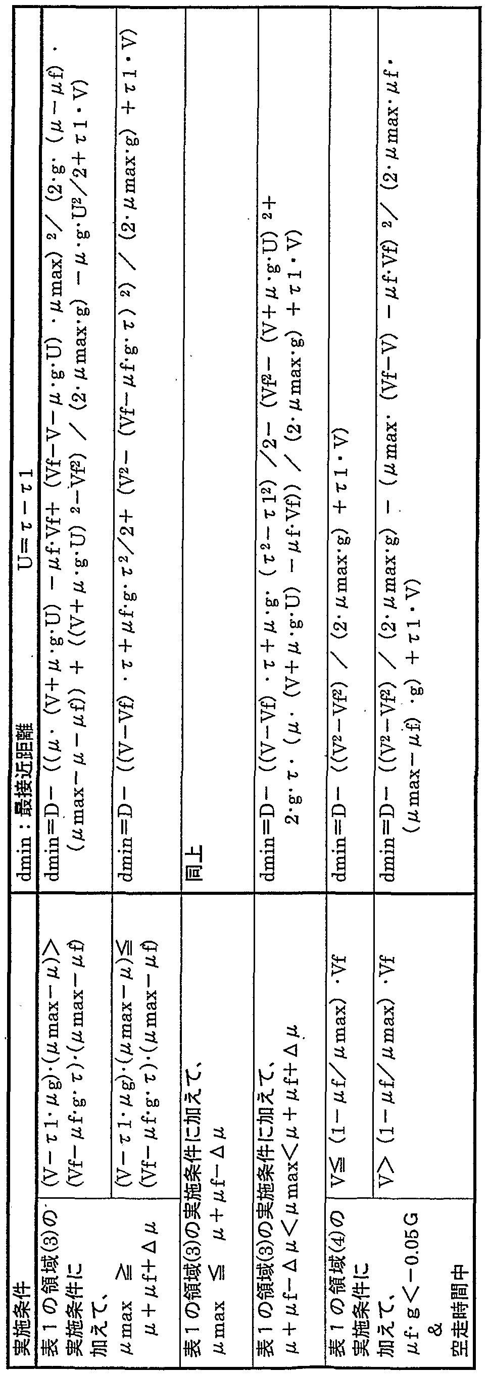
図 1 1 は、 横軸に先行車の減速度 ^ f · g を、 縦軸に同先行車の 速度 V fをとつて、 最接近距離を算出するための条件を領域によ り 示した図である。 Figure 11 shows the conditions for calculating the closest approach distance by region, with the deceleration of the preceding vehicle ^ fg on the horizontal axis and the speed Vf of the preceding vehicle on the vertical axis. It is.
図 1 2 は、 図 1 に示したダイヤルスィ ッチで選択可能な因子 (パ ラメ一夕) の大きさを示した図である。 Fig. 12 is a diagram showing the size of the factors (parameters) that can be selected with the dial switch shown in Fig. 1.
図 1 3 は、 自車を追い抜いた車両が自車の前方に割込む場合を模
式的に示した図である。 Figure 13 shows a case in which a vehicle that overtakes the vehicle and cuts in front of the vehicle. FIG.
図 1 4 は、 図 1 に示した C P Uが実行するメイ ンルーチンを示す フローチヤ一卜である。 FIG. 14 is a flowchart showing a main routine executed by the CPU shown in FIG.
図 1 5 は、 図 1 に示した C P Uが実行する停車モー ドのルーチン を示すフローチャー トである。 . FIG. 15 is a flowchart showing a stop mode routine executed by the CPU shown in FIG. .
図 1 6 は、 図 1 に示した C P Uが実行する非警報モー ドのル一チ ンを示すフローチヤ一 トである。 FIG. 16 is a flowchart showing a routine in the non-alarm mode executed by the CPU shown in FIG.
図 1 7 は、 図 1 に示した C P Uが実行する警報 · 介入発令判断サ ブル一チンを示すフローチヤ一 トである。 FIG. 17 is a flowchart showing a subroutine of the alarm / intervention issue determination executed by the CPU shown in FIG.
図 1 8 は、 図 1 に示した C P Uが実行する警報判断サブル一チン を示すフロ一チヤ一トである。 FIG. 18 is a flowchart showing an alarm judgment subroutine executed by the CPU shown in FIG.
図 1 9 は、 図 1 に示した C P Uが実行する警報モー ドのルーチン を示すフロ一チヤ一 トである。 FIG. 19 is a flowchart showing a routine of an alarm mode executed by the CPU shown in FIG.
図 2 0 は、 図 1 に示した C P Uが実行する 目標減速度を演算する サブル一チンを示すフロ一チヤ一トである。 FIG. 20 is a flowchart showing a subroutine for calculating a target deceleration executed by the CPU shown in FIG.
図 2 1 は、 図 1 に示した C P Uが実行する介入制動モー ドのル一 チンを示すフローチヤ一 トである。 FIG. 21 is a flowchart showing the routine of the intervention braking mode executed by the CPU shown in FIG.
図 2 2 は、 図 1 に示した C P Uが実行する G抜きモー ドのル一チ ンを示すフローチヤ一 トである。 FIG. 22 is a flowchart showing a routine in the G-extraction mode executed by the CPU shown in FIG.
図 2 3 は、 図 1 に示した C P Uが実行する車間制御モー ドのルー チンを示すフローチャー トである。 Fig. 23 is a flowchart showing the routine of the headway control mode executed by the CPU shown in Fig. 1.
図 2 4は、 車間距離センサの検出可能エリ ア (検出エリ ア) と認 知限界を模式的に示した図である。 Figure 24 is a diagram schematically showing the detectable area (detection area) and the recognition limit of the inter-vehicle distance sensor.
図 2 5 Aは、 演算される目標減速度の時間変化を示した図である 図 2 5 Bは、 介入制動開始直後に前記演算された目標減速度を増 大させた場合の同目標減速度の時間変化を示した図である。 Fig. 25A is a diagram showing the change over time of the calculated target deceleration. Fig. 25B is the same target deceleration when the calculated target deceleration is increased immediately after the start of intervention braking. FIG. 5 is a diagram showing a time change of the sigma.
図 2 6 は、 μ m a xチェッ ク制御を説明するために、 自車及び先行 車の時間に対する速度変化を示した図である。
発明を実施するための最良の形態 FIG. 26 is a diagram showing speed changes of the own vehicle and the preceding vehicle with respect to time in order to explain the μ max check control. BEST MODE FOR CARRYING OUT THE INVENTION
以下、 本発明による車両の衝突予防装置の一実施形態について図 面を参照しつつ説明する。 図 1 は同実施形態に係る衝突予防装置の 概略構成を示している。 この衝突予防装置は車両に搭載された電気 制御装置 1 0 を備え、 同電気制御装置 1 0 は図示しないバスを介し て互いに接続された C P U 1 0 a、 R O M 1 0 b、 及び R A M I 0 c 等からなるマイ クロコ ンピュータ と して構成されている。 C P U 1 0 a は、 R O M 1 O b に格納された後述するプログラムを、 R A M l 0 c の一時記憶機能を利用しながら実行するよう になっている 電気制御装置 1 0 には、 車速センサ 1 1 、 障害物センサと しての 車間距離センサ 1 2 、 相対速度センサ 1 3 、 ダイヤルスィ ッチ 1 4 、 加速度センサ 1 5 、 シフ ト レバ一スィ ッチ 1 6 、 ブレーキスイ ツ チ 1 7 、 左前輪速度センサ 1 8 、 右前輪速度センサ 1 9 、 左後輪速 度センサ 2 0 、 及び右後輪速度センサ 2 1 が接続され、 C P U 1 0 aはこれらのセンサ及びスィ ツチからの信号を入力するよう になつ ている。 また、 電気制御装置 1 0 は、 警報装置 3 0 、 及びブレーキ ァクチユエ一夕 4 0 と接続されていて、 C P U 1 0 a はこれら に対 し所定の信号を供給するよう になっている。 Hereinafter, an embodiment of a vehicle collision prevention device according to the present invention will be described with reference to the drawings. FIG. 1 shows a schematic configuration of a collision prevention device according to the embodiment. This collision prevention device includes an electric control device 10 mounted on a vehicle, and the electric control device 10 includes a CPU 10a, a ROM 10b, a RAMI 0c, and the like connected to each other via a bus (not shown). It is configured as a micro computer consisting of The CPU 10a executes a program, which will be described later, stored in the ROM 10Ob while using the temporary storage function of the RAM 10c. The electric control device 10 includes a vehicle speed sensor 11 , Inter-vehicle distance sensor 12 as an obstacle sensor, relative speed sensor 13, dial switch 14, acceleration sensor 15, shift lever switch 16, brake switch 17, left The front wheel speed sensor 18, the right front wheel speed sensor 19, the left rear wheel speed sensor 20, and the right rear wheel speed sensor 21 are connected, and the CPU 10 a inputs signals from these sensors and switches. It's about to do. Further, the electric control unit 10 is connected to the alarm unit 30 and the brake factory 40, and the CPU 10a supplies a predetermined signal to them.
車速センサ 1 1 は、 自車 (自己の車両) の速度を検出して自車の 速度 (自車速) Vを出力するよう になっている。 車間距離センサ 1 2 は、 レーザ一レーダを含んで構成されていて、 自車と先行車 (自 車の前方に位置する車両、 前車とも云う。 ) との距離を計測し、 車 間距離 Dを出力するよう になっている。 なお、 車間距離センサ 1 2 は、 ミ リ波レーダを使用 して車間距離 Dを計測するものであっても よく 、 ステレオ式画像認識手法を用いて車間距離 Dを計測する もの であってもよい。 The vehicle speed sensor 11 detects the speed of the own vehicle (own vehicle) and outputs the speed (own vehicle speed) V of the own vehicle. The inter-vehicle distance sensor 12 includes a laser radar, measures the distance between the own vehicle and a preceding vehicle (also referred to as a vehicle located in front of the own vehicle, also referred to as a front vehicle), and obtains an inter-vehicle distance D. Is output. The inter-vehicle distance sensor 12 may measure the inter-vehicle distance D using a millimeter wave radar, or may measure the inter-vehicle distance D using a stereo image recognition method. .
相対速度センサ 1 3 は、 先行車の走行状態を検出する先行車走行 状態検出手段の一部を構成し、 ミ リ波を使用 した ドップラーセンサ であって、 自車と先行車との相対速度 RVを出力するよう になって いる。 ダイヤルスィ ッチ 1 4 は、 運転者によって 7 つの位置に切替
え操作されるよう になっていて、 操作された各位置に応じた選択位 置信号 S Tを出力するよう になっている。 このダイヤルスィ ッチ 1 4 は、 空走時間 て を決める因子 (以下、 因子又はパラメ一夕 と呼ぶ。 ) である同空走時間 て 、 自車想定減速度 · g を決める因子である 11 、 適正車間距離 D tを決める因子である車頭時間 T dの組を複数組 記憶した因子記憶手段の一部を構成している。 これらの因子につい ては後述する。 The relative speed sensor 13 constitutes a part of the preceding vehicle traveling state detecting means for detecting the traveling state of the preceding vehicle, is a Doppler sensor using millimeter waves, and has a relative speed RV between the own vehicle and the preceding vehicle. Is output. Dial switch 14 can be switched between seven positions by the driver The selected position signal ST corresponding to each operated position is output. The dial switch 14 is a factor that determines the own vehicle's assumed deceleration · g, which is a factor that determines the idle running time (hereinafter, referred to as a factor or a parameter) 11, It constitutes a part of the factor storage means that stores a plurality of sets of headway times Td, which are factors that determine the appropriate inter-vehicle distance Dt. These factors will be described later.
加速度センサ 1 5 は、 半導体式であって、 自車の前後方向に作用 する加速度を検出して加速度信号 Gを出力するよう になっている。 シフ ト レバースィ ッチ 1 6 は、 図示しない自車の自動変速機のシフ ト レバー位置 (パーキング位置 P、 リバ一ス位置 R、 ドライ ブ位置 D 等) を検出し、 信号 P 0 Sと して出力するよ う になっている。 ブレ 一キスイ ッチ 1 7 は、 図示を省略した自車のブレーキペダルの操作 • 非操作状態を検出して、 同ペダルが操作されている とき値 「 1 」 、 操作されていないとき値 「 0」 となる信号 S T OPを出力するよう に なっていて、 運転者によってブレーキ装置が作動状態とされている か否かを判定するブレーキ作動判定手段の一部を構成している。 The acceleration sensor 15 is of a semiconductor type, and detects acceleration acting in the longitudinal direction of the vehicle and outputs an acceleration signal G. The shift lever switch 16 detects the shift lever position (parking position P, reverse position R, drive position D, etc.) of the automatic transmission (not shown) of the own vehicle, and outputs the signal P0S. It is designed to output. The brake switch 17 detects the operation of the brake pedal (not shown) of the own vehicle. The value is “1” when the pedal is operated and the value “0” when the pedal is not operated. And outputs a signal STOP, which constitutes a part of the brake operation determining means for determining whether or not the driver has activated the brake device.
左前輪速度センサ 1 8及び右前輪速度センサ 1 9 は、 それぞれ左 前輪 (自 由輪) の車輪速度 VF L, 右前輪 (自由輪) の車輪速度 VF Rを 検出して出力するよう になっている。 同様に、 左後輪速度センサ 2 0 及び右後輪速度センサ 2 1 は、 それぞれ左後輪 (駆動輪) の車輪 速度 V R L ,右後輪 (駆動輪) の車輪速度 V RRを検出して出力するよう になっている。 The front left wheel speed sensor 18 and the front right wheel speed sensor 19 detect and output the wheel speed VF L of the front left wheel (free wheel) and the wheel speed VF R of the front right wheel (free wheel), respectively. I have. Similarly, the left rear wheel speed sensor 20 and the right rear wheel speed sensor 21 detect and output the wheel speed VRL of the left rear wheel (drive wheel) and the wheel speed VRR of the right rear wheel (drive wheel), respectively. It is supposed to.
警報装置 3 0 は、 図示を省略したディ スプレイ と警告音発生装置 とを含んでいて、 電気制御装置 1 0 の C P U 1 0 aからの指示に応 じて、 必要な表示及び警告音の発生を行うよう になっている。 ブレ 一キアクチユエ一夕 4 0 は、 図示しないブレーキ装置の制動油圧 ( ブレーキ油圧) を、 ブレーキペダル操作によって増減されるブレー キマスタシリ ンダによる制動油圧とは独立して制御し、 左右前輪及 び左右後輪に備えられた油圧式ブレーキによる制動力を変更するよ う になつている。 なお、 ブレーキ装置が電動モータの発生 トルクに
よ り制動力を発生する電動式ブレーキである場合には、 前記ブレー キアクチユエ一夕 4 0 は同電動モータに相当する。 The alarm device 30 includes a display (not shown) and a warning sound generation device, and generates a necessary display and generation of a warning sound in response to an instruction from the CPU 10 a of the electric control device 10. It is supposed to do it. The brake actuator 40 controls the brake oil pressure (brake oil pressure) of a brake device (not shown) independently of the brake oil pressure of the brake master cylinder that is increased or decreased by operating the brake pedal. The braking force of the hydraulic brake provided in the vehicle is changed. In addition, the braking device In the case of an electric brake that generates more braking force, the brake actuator 40 corresponds to the electric motor.
次に、 このよう に構成された衝突予防装置の作動原理について説 明する。 この衝突予防装置は、 先行車との間に安全な距離を確保す る こ とを目的と し、 先行車及び自車の状態等に基づいて一次警報を 行い、 続いて二次警報を行う こ とで運転者に制動操作を促し、 二次 警報によっても制動操作がなされない場合には、 自動的に制動装置 を作動させる介入制動を行う よう になっている。 また、 一次又は二 次警報によ り運転者が制動操作を行った場合であっても、 その制動 力が目標減速度 G Tに対して不足している場合には、 制動力を増大 する (制動操作をアシス ト (ブレーキアシス ト) する) よう になつ ている。 Next, the operation principle of the thus configured collision prevention device will be described. The purpose of this collision prevention device is to secure a safe distance from the preceding vehicle, and to issue a primary alarm based on the conditions of the preceding vehicle and the host vehicle, and then to issue a secondary alarm. In this way, the driver is prompted to perform a braking operation, and if the braking operation is not performed even by the secondary alarm, intervention braking for automatically operating the braking device is performed. Also, even if the driver performs a braking operation due to the primary or secondary alarm, if the braking force is insufficient for the target deceleration GT, the braking force is increased (braking The operation is assisted (brake assist).
この衝突予防装置は、 上記一次警報と しては、 上記警報装置 3 0 の警告音発生装置か ら相対的に穏やかな警告音 (例えば、 音量は普 通で、 間歇的に発生される警告音) を発生するよう になっている。 二次警報は、 警報装置 3 0 の警告音発生装置から一次警報よ り も運 転者の注意を一層喚起する警告音 (例えば、 音量は普通で、 連続的 に発生される警告音) を発生する と ともに、 同警報装置のディ スプ レイ に注意を喚起するマーク を表示するよう になっている。 また、 介入制動時においては、 上記二次警報と同様の警報を行うが、 音量 は大きく されるよう になつている。 In the collision prevention device, as the primary warning, a relatively gentle warning sound from the warning sound generating device of the warning device 30 (for example, a normal sound volume and a warning sound generated intermittently). ). The secondary alarm generates a warning sound from the warning device of the alarm device 30 that raises the driver's attention more than the primary warning (for example, a normal volume sound and a continuous warning sound). At the same time, a warning symbol is displayed on the display of the alarm device. Also, at the time of intervention braking, the same alarm as the above-mentioned secondary alarm is issued, but the volume is increased.
本実施形態においては、 一次警報、 二次警報、 及び介入制動は、 先行車の状態、 自車の状態等に基づいて図 2 に示した最接近距離 ( 自車と先行車が最も接近したときの距離) dm i nを計算によ り予測し 、 同最接近距離 d m i nが所定の適正車間距離 D tを確保できない (dm i n < D t ) と判断されたときに実行されるよう になっている。 また、 一次警報、 二次警報、 及び介入制動の何れを実行すべきかは、 上記 最接近距離 dm i nを求める際に使用されるパラメータ (後述する、 空 走時間 て 、 自車想定減速度 · g ( gは重力加速度) ) 、 及び適正 車間距離 D tを決定するパラメ一夕 (後述する車頭時間 T d ) を変更 する こ とで決定されるよ う になっている。 そこで、 先ず、 最接近距
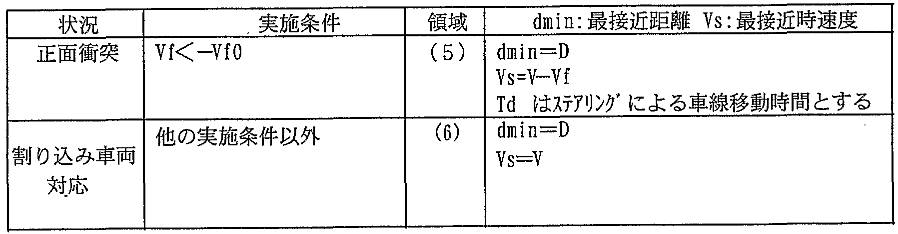
離 dm i nの求め方から説明する。 In the present embodiment, the primary alarm, the secondary alarm, and the intervention braking are performed based on the state of the preceding vehicle, the state of the own vehicle, and the like, based on the closest approach distance shown in FIG. 2 (when the own vehicle and the preceding vehicle Dm in is calculated and predicted, and executed when it is determined that the closest approach distance dmin cannot secure a predetermined appropriate inter-vehicle distance D t (dm in <D t). . Whether the primary alarm, the secondary alarm, or the intervention braking should be executed is determined by the parameters used when calculating the above-described closest approach distance dmin (described later, the idle running time, the estimated deceleration of the vehicle, g (g is the gravitational acceleration)), and the parameter for determining the appropriate inter-vehicle distance D t (the headway time T d described later) is changed. Therefore, first, the closest approach distance We will start with how to find the dm in.
(最接近距離 d m i n ) (Closest approach distance d min)
最接近距離 d m i nは、 現時点 ( t == 0 ) における先行車の車速が V ίであ り 同先行車が現時点で検出される減速度 f · g を一定に維持 しながら減速 (又は加速) し、 自車は現時点から空走時間 て だけ現 時点の速度 Vで走行した後に一定減速度 (自車の想定減速度) a · gで減速するものと仮定し、 この仮定と現時点における実際の車間 距離 (先行車と自車の距離) Dに基づいて求め られる。 このとき、 最接近距離 d m i nは、 ( 1 ) 先行車が先に停止し自車が続いて停止す る場合、 ( 2 ) 先行車が当初から停止している場合、 ( 3 ) 空走時 間 τが経過した後に走行中の先行車に自車が最接近する場合、 ( 4 ) 空走時間 てが経過する前に自車が先行車に最接近する場合の四通 り に場合分けして検討する必要があ り、 以下に述べるよう に求めら れる。 The closest approach distance dmin is that the vehicle speed of the preceding vehicle at the current time (t == 0) is Vί, and the preceding vehicle decelerates (or accelerates) while maintaining the deceleration f · g detected at the current time constant. Then, it is assumed that the vehicle travels at the current speed V only for the idle running time from the current time and then decelerates at a constant deceleration (the assumed deceleration of the vehicle) a · g. Distance (distance between preceding vehicle and own vehicle) Calculated based on D. At this time, the closest approach distance dmin is as follows: (1) when the preceding vehicle stops first and then the own vehicle stops, (2) when the preceding vehicle stops from the beginning, (3) idle running time (4) When the vehicle approaches the preceding vehicle before the running vehicle elapses after the elapse of τ, (4) when the vehicle approaches the preceding vehicle before the idling time elapses This needs to be considered and is required as described below.
上記各場合についての検討に先立ち、 以下に用いる基本的な計算 式について確認する と、 初速 V 0の車両が減速度 0;—定で停止する までに要する時間 (停止時間) t は下記式 1 で表される。 Prior to examining each of the above cases, the basic formulas used below were checked. The time required for the vehicle with initial speed V0 to decelerate 0; It is represented by
t = V 0 Z ひ…式 1 t = V 0 Z… Equation 1
また、 初速 V 0、 減速度 α の車両が走行する距離 D 0は、 下記式 2で表される。 The distance D 0 traveled by the vehicle having the initial speed V 0 and the deceleration α is expressed by the following equation (2).
D 0 = V 0 · t - · t 2 / 2 …式 2 D 0 = V 0 · t - · t 2/2 ... Equation 2
従って、 上記式 2 に上記式 1 の停止時間 t を代入する こ とで、 初 速 V 0、 減速度ひ の車両が停止するまでに走行する距離 D Lは、 下記 式 3 のよう に求められる。 Therefore, by substituting the stop time t of the above equation 1 into the above equation 2, the distance D L traveled before the vehicle with the initial speed V 0 and the deceleration is stopped can be obtained as the following equation 3.
D L = V 0 V ( 2 · α ) …式 3 D L = V 0 V (2 · α) ... Equation 3
( 1 ) 先行車が先に停止し自車が続いて停止する場合 (1) When the preceding vehicle stops first and the own vehicle stops subsequently
図 3 は、 先行車が先に停止しその後自車が停止する場合における 同先行車及び同自車の時間に対する車速変化を示し、 図 4 は同場合 における同先行車及び同自車の時間に対する位置変化を示している 。 先行車が停止するまでの時間 t f は、 上記式 1 か ら明らかなよ う に、 下記式 4 によ り表される。
t f = V f/ ( f ' g ) …式 4 Fig. 3 shows the change in vehicle speed with respect to the time of the preceding vehicle and the same vehicle when the preceding vehicle stops first and then the own vehicle stops. The position change is shown. The time tf until the preceding vehicle stops is expressed by the following equation 4, as is apparent from equation 1 above. tf = V f / (f 'g) ... Equation 4
従って、 先行車が停止する位置 D f は、 現時点での自車の位置を 基準と した場合、 上記式 2 及び図 4から明 らかなよう に、 下記式 5 によ り表される。 Therefore, the position D f at which the preceding vehicle stops is expressed by the following expression 5, as is clear from the above expression 2 and FIG. 4, based on the current position of the own vehicle.
D f = D + V f V ( 2 · a f · g ) …式 5 D f = D + V f V (2 · a f · g) ... Equation 5
一方、 自車が停止するまでの時間 t jは、 上記式 1 及び図 4か ら 明らかなよう に、 下記式 6 によ り表される。 On the other hand, the time t j until the own vehicle stops is expressed by the following equation 6, as is apparent from the above equation 1 and FIG.
t j = て + V / ( · g ) …式 6 t j = t + V / (· g)… Equation 6
また、 自車が停止する位置 D jは、 上記式 3 及び図 4か ら明 らか なよう に、 下記式 7 によ り表される。 Further, the position D j at which the host vehicle stops is expressed by the following equation 7, as is apparent from the above equation 3 and FIG.
D j = V · て + V2Z ( 2 · ^ · g ) …式 7 D j = V · + V 2 Z (2 · ^ · g) ... Equation 7
従って、 上記式 5 及び上記式 7 から、 自車が停止したときの最接 近距離 dmin ( = D f — D j) は下記式 8 によ り表される。 Therefore, from the above formulas 5 and 7, the closest distance dmin (= D f —D j) when the vehicle stops is expressed by the following formula 8.
dmi n= { D + V f V ( 2 · f · g ) } - { V · r + W ( 2 · H · g ) } …式 8 dmin = {D + V f V (2 · f · g)}-{V · r + W (2 · H · g)}… Equation 8
式 8 が成立する条件 (式 8 を用いて最接近距離 dminを計算すべき 条件、 以下、 単に 「実施条件」 と云う。 ) は、 先行車が停止するま での時間 t fが自車が停止するまでの時間 t ] '以下であるこ とから、 上記式 4及び上記式 6 に基づいて下記式 9 によ り表される。 The condition that satisfies Equation 8 (the condition for calculating the closest approach distance dmin using Equation 8; hereinafter, simply referred to as the “execution condition”) is that the time tf until the preceding vehicle stops is the time at which the host vehicle stops. Since the time t] is equal to or shorter than the time t] ′, it is expressed by the following equation 9 based on the above equations 4 and 6.
V ϊ≤ ί - g - { r + V Z i z ' g ) } …式 9 V ϊ≤ ί-g-{r + V Z i z 'g)}… Equation 9
この他に、 先行車が減速している こと、 及び相対速度センサ 1 3 の検出能力を考え、 速度の絶対値が一定速度 V fO ( V f0> 0 ) 未満 の車両については停止している車両と して扱うために上記式 8 には 、 それぞれ下記の式 1 0及び式 1 1 の実施条件が加えられる。 なお 、 最接近速度 V sは 「 0'」 である。 In addition to this, considering that the preceding vehicle is decelerating and the detection capability of the relative speed sensor 13, vehicles that have stopped at speeds whose absolute value is less than the constant speed V fO (V f0> 0) In order to treat as above, the implementation conditions of the following Expressions 10 and 11 are added to Expression 8 above. Note that the maximum approach speed V s is “0 ′”.
ϊ≥ 0 …式 1 0 ϊ≥ 0… Equation 1 0
V f≥ V f 0-式 1 1 V f≥ V f 0-Equation 1 1
( 2 ) 先行車が当初から停止している場合 (静止物である場合) この場合、 先行車の位置 D f は現時点における車間距離 Dである か ら、 これと上記式 7 に示された自車が停止する位置 D ]'とか ら、 下記式 1 2 が得られる。 また、 この場合の実施条件は、 前記式 1 1
を条件と して設けた理由 と同じ理由によ り、 下記式 1 3で表される 。 なお、 最接近速度 V sは 「 0」 である。 (2) When the preceding vehicle is stopped from the beginning (when it is a stationary object) In this case, since the position D f of the preceding vehicle is the current inter-vehicle distance D, this and the self- From the position D] 'at which the car stops, the following equation 12 is obtained. In this case, the execution condition is expressed by the above-mentioned equation 11 For the same reason that the condition was established as a condition, it is expressed by the following expression 13. The maximum approach speed V s is “0”.
dmin= D - { V - r + W ( 2 · n · g ) } …式 1 2 dmin = D-{V-r + W (2 · n · g)}… Equation 1 2
I V f I < V f 0 …式 1 3 I V f I <V f 0… Equation 1 3
( 3 ) 空走時間 てが経過した後に走行中の先行車に自車が最接近す る ¾口 (3) After the idle running time has elapsed, the vehicle will approach the preceding vehicle that is traveling.
図 5 は、 自車の空走時間後であって、 先行車が減速度 f * g ( II f - g > 0 ) で減速しながら走行している間に自車が同先行車に 最接近する場合における同自車及び同先行車の時間に対する車速変 化を示し、 図 6 は同場合における同自車及び同先行車の時間に対す る位置変化を示している。 また、 図 7 は、 先行車が減速度 f · g ( f · g < 0 ) で減速、 即ち加速しながら走行している間に自車 が同先行車に最接近する場合における同自車及び同先行車の時間に 対する車速変化を示し、 図 8 は同場合における同自車及び同先行車 の時間に対する位置変化を示している。 Figure 5 shows that the vehicle comes closest to the preceding vehicle while the vehicle is running while decelerating at a deceleration f * g (IIf-g> 0) after the vehicle's idle time. In this case, the change in vehicle speed with respect to the time of the same vehicle and the preceding vehicle is shown. Fig. 7 shows the case where the preceding vehicle decelerates at the deceleration f · g (f gg <0), that is, when the vehicle comes closest to the preceding vehicle while driving while accelerating. The vehicle speed change with time of the preceding vehicle is shown, and Fig. 8 shows the position change of the own vehicle and the preceding vehicle with respect to time in the same case.
いずれの場合においても (減速度 ^ ί · g の正負に関わ らず) 、 自車が先行車に最接近するのは、 自車の速度 V ' と先行車の速度 V f 'が等しい速度 V sとなった場合である。 両車の速度が等しい速度 V sとなる時間を t cとする と、 その時点の自車の速度 V ' 、 及び先 行車の速度 V f ' は、 図 5 及び図 7 から明らかなよ う に、 下記式 1 4及び下記式 1 5 によ りそれぞれ表される。 In either case (regardless of whether the deceleration ^ ^ · g is positive or negative), the vehicle is closest to the preceding vehicle only when the speed V 'of the vehicle is equal to the speed Vf' of the preceding vehicle. This is the case when it becomes s. Assuming that the time at which the speeds of both vehicles are equal Vs is tc, the speed V 'of the own vehicle at that time and the speed Vf' of the preceding vehicle at that time are, as is clear from Figs. 5 and 7, It is expressed by the following equations 14 and 15, respectively.
V ' = V - 2 - g - ( t c— て) …式 1 4 V '= V-2-g-(t c — te)… Equation 1 4
V f ' = V f - ^ f - g - t c …式 1 5 V f '= V f-^ f-g-t c ... Equation 1 5
両拿の速度が等しい速度 V sになるまでの時間 t cは、 上記式 1 4 の右辺と上記式 1 5 の右辺が等しいこ とから、 下記式 1 6 によ り表 される。 The time tc until the speed of both knives becomes equal to the speed Vs is expressed by the following expression 16 because the right side of the above expression 14 and the right side of the above expression 15 are equal.
t c = V一 V f + · g · て ) / ( 11 · g — /2 f · g ···式 1 6 一方、 時間 t c 後の先行車の位置 D f は、 上記式 2 、 図 4 、 及び 図 6から明らかなよう に、 下記式 1 7 によ り表される。 tc = V-Vf + · g ·) / (11 · g — / 2 f · g · Equation 16 On the other hand, the position D f of the preceding vehicle after time tc is calculated by the above equation 2, Figure 4, As apparent from FIG. 6 and FIG.
D f = D + V f · t c- f * g · 2/ 2 "'式 1 1 D f = D + V f · t c- f * g · 2/2 "' Formula 1 1
また、 時間 t c 後の自車の位置 D jは、 上記式 2 、 図 5 、 及び図
7から、 下記式 1 8 によ り表される。 In addition, the position D j of the own vehicle after time tc is calculated according to the above equation 2, FIG. 5, and FIG. From Equation 7, it is expressed by the following equation 18.
D j = V · て + V ( t c一 て ) - ' g ■ ( t c- r ) V 2 …式 1 8 D j = V · te + V (t c)-'g ■ (t c-r) V 2… Eq. 18
従って、 式 1 6 〜式 1 8 によ り 、 最接近距離 dm i nは下記式 1 9 に よ り表される。 Therefore, according to Equations 16 to 18, the closest approach distance dm in is expressed by Equation 19 below.
dmin= D - [ ( V + · g · τ - V f ) V { 2 ( ~ ϊ) · g } - • g · て 2 Z 2 ]…式 1 9 dmin = D - [(V + · g · τ - V f) V {2 (~ ϊ) · g} - • g · Te 2 Z 2] ... Equation 1 9
このとき、 上記式 1 5 (又は上記式 1 4 ) と上記式 1 6 とから、 最接近時の速度 V sは、 下記式 2 0 によ り表される。 At this time, the velocity V s at the time of the closest approach is expressed by the following equation 20 from the above equation 15 (or the above equation 14) and the above equation 16.
V S = [1 ί ' V— 2 · V f + /2 · 11 f · g · て ) ·/ ( n I— 11 ) …式 2 0 V S = [1 ί 'V— 2 · V f + / 2 · 11 f · g ·) · / (n I— 11)… Eq. 20
また、 上記式 1 9 及び上記式 2 0 の実施条件は、 下記式 2 1 で表 される条件が付加される。 Further, the conditions represented by the following expression 21 are added to the implementation conditions of the above expression 19 and the above expression 20.
て く t cく t j …式 2 1 T t c t t… Equation 2 1
上記式 2 1 に、 上記式 1 6及び上記式 6 を適用する と、 下記の式 2 2及び式 2 3 が得られる。 When the above equations 16 and 6 are applied to the above equation 21, the following equations 22 and 23 are obtained.
V f < f · g - r + V …式 2 2 V f <f · g-r + V ... Eq. 2 2
V ί> ί · g · { τ + V / ( a · g ) } …式 2 3 V ί> ί · g · {τ + V / (a · g)}… Equation 2 3
なお、 式 2 3 は、 先行車が加速 ( f · g < 0 ) している場合に は当然に成立する。 また、 上記式 1 9及び上記式 2 0 の実施条件に は、 上記式 1 1 の条件 ( V f≥ V fO) が付加される。 Equation 23 naturally holds when the preceding vehicle is accelerating (f · g <0). In addition, the condition (Vf≥VfO) of the above equation 11 is added to the implementation conditions of the above equations 19 and 20.
( 4 ) 空走時間 τが経過する前に自車が先行車に最接近する場合 図 9 は、 空走時間 τが経過する前に自車が先行車に最接近する場 合における同自車及び同先行車の時間に対する車速変化を示し、 図 1 0 は同場合における同自車及び同先行車の時間に対する位置変化 を示している。 この場合においても、 自車が先行車に最接近するの は、 自車の速度 V ' と先行車の速度 V f ' が等しい速度 V sとなった 場合である。 両車の速度が等しい速度 V sとなる時間を t cとする と 、 自車の速度 V ' は速度 V—定であるから、 先行車の速度を考慮し て下記式 2 4が成立する。 (4) When the vehicle approaches the preceding vehicle before the idle time τ elapsesFigure 9 shows the vehicle when the vehicle approaches the preceding vehicle before the idle time τ elapses And the vehicle speed change with time of the preceding vehicle. FIG. 10 shows the positional change of the own vehicle and the preceding vehicle with respect to time in the same case. Also in this case, the own vehicle comes closest to the preceding vehicle when the speed V 'of the own vehicle and the speed Vf' of the preceding vehicle are equal to each other, ie, Vs. Assuming that the time at which the speeds of both vehicles are equal to the speed Vs is tc, the speed V 'of the own vehicle is the speed V—constant, and the following formula 24 is established in consideration of the speed of the preceding vehicle.
V = V f - f · g · t (;…式 2 4
一方、 時間 t c 後の先行車の位置 D f は、 上記式 2 及び図 0 力 ら明らかなよう に、 下記式 2 5 によ り表される。 V = V f-f · g · t (;… Equation 24 On the other hand, the position D f of the preceding vehicle after the time tc is expressed by the following equation 25, as is apparent from the above equation 2 and FIG.
D f = D + V f · t c— ( ί · g · t c2) 2 "-式 2 5 D f = D + V f · tc— (ί · g · tc 2 ) 2 "-Equation 2 5
また、 時間 t c 後の自車の位置 D jは、 図 1 0 か ら下記式 2 6 に よ り表される。 Further, the position D j of the own vehicle after the time t c is represented by the following equation 26 from FIG.
D j = V · t c…式 2 6 D j = V · t c ... Equation 2 6
従って、 式 2 4〜式 2 6 によ り 、 変数 t cを消去すれば最接近距 離 dminは下記式 2 7 によ り表される。 . dmin= D - ( V - V f) { - 2 · { n I - g ) } …式 2 7 このとき、 最接近時速度 V sは、 下記式 2 8 のよ う に、 当然に自 車の速度 Vと等しい。 Accordingly, according to Equations 24 to 26, if the variable tc is eliminated, the closest approach distance dmin is expressed by Equation 27 below. dmin = D-(V-V f) {-2 · {n I-g)}… Equation 2 7 At this time, the speed V s at the time of closest approach is, of course, as shown in Equation 28 below. Speed equal to V.
V s= V…式 2 8 V s = V… Equation 2 8
上記式 2 7 及び式 2 8 の実施条件は、 空走時間 て の経過前に時間 t cが経過する こ と ( t c≤ r ) で るから、 下記式 2 9が該当する 。 また、 現時点での先行車の速度 V fが相対速度センサの検出精度 V fOを超えている こ と、 現時点の先行車の速度 V fが自車の速度 V よ り小さいこ と、 先行車が加速中である こ とから、 下記式 3 0 〜下 記式 3 2 となる Since the execution conditions of the above equations 27 and 28 are that the time tc elapses before the idling time elapses (tc≤r), the following equation 29 applies. Also, that the current speed V f of the preceding vehicle exceeds the detection accuracy V fO of the relative speed sensor, that the current speed V f of the preceding vehicle is lower than the speed V of the host vehicle, and that the preceding vehicle Since the vehicle is accelerating, the following formulas (30) to (32)
V f≥ f · g τ + V 式 2 9 V f≥fg τ + V Equation 2 9
V f≥ V f 0 式 3 0 V f≥ V f 0 Equation 3 0
V f< V 式 3 1 V f <V Equation 3 1
式 3 2 Equation 3 2
以上をまとめる と、 下記表 1 に示したよう になる。 また、 図 1 1 は横軸に先行車の減速度 f * g を、 縦軸に同先行車の速度 V f をと つて、 上記各場合分け ( 1 ) 〜 ( 4 ) の領域を示したものである。
(表 1 ) The above is summarized in Table 1 below. In Fig. 11, the horizontal axis shows the deceleration f * g of the preceding vehicle, and the vertical axis shows the speed Vf of the preceding vehicle. It is. (table 1 )
こ こで、 上記空走時間 τ 、 及び自車想定減速度 · gについて説 明する。 上述したよう に、 本実施形態においては、 先ず一次警報を 行って運転者に制動操作を促し、 次いで二次警報を行う ことで運転 者に制動操作を更に促し、 二次警報によっても制動操作がなされな い場合には、 自動的に制動装置を作動させる介入制動を行う。 Here, the idle running time τ and the assumed deceleration g of the vehicle will be described. As described above, in the present embodiment, first, a primary alarm is issued to urge the driver to perform a braking operation, and then, a secondary alarm is issued to further urge the driver to perform a braking operation. If not, intervention braking is performed to automatically activate the braking system.
(空走時間 τ ) (Running time τ)
このことを考慮して、 一次警報用空走時間 て (第 1 空走時間) は 運転者が通常の運転操作の中で最も緊迫したタイ ミ ングで制動操作 を行う場合に基づいて設定する。 二次警報用空走時間 て (第 2空走 時間) は運転者が緊急の運転操作の中で最も緊迫したタイ ミ ングで 制動操作を行う場合に基づいて設定する。 介入制動用空走時間 て ( 第 2 又は第 3空走時間) は運転者の制動操作によ らない自動制動動 作を前提として設定する。 In consideration of this, the primary warning idle running time (first idle running time) is set based on the case where the driver performs the braking operation at the most nervous timing during the normal driving operation. The idling time for secondary alarm (second idling time) is set based on the case where the driver performs the braking operation at the most nervous timing of emergency driving operations. The idle running time for intervention braking (second or third idle running time) is set on the premise that the automatic braking operation does not depend on the driver's braking operation.
よ り具体的に述べると、 空走時間 て には、 少なく とも、 図 1 に示 したセンサ 1 1 〜 2 1 等及び電気制御装置 1 0が、 先行車及び自車 の状態等 (特に、 先行車の減速度 f * g ) を認識する時間と一次 , 二次警報又は介入制動の必要性を判断するために必要とする演算 処理時間の和 ( て 1 ) と、 電気制御装置 1 0 がブレ一キアクチユエ —夕 4 0 に対して制動力を発生させるよう に指示信号を出力 してか ら実際にブレーキ油圧が上昇して制動力が発生し始めるまでの時間
( て 2 ) が含まれる。 More specifically, during idle running time, at least the sensors 11 to 21 and the electric control device 10 shown in FIG. The sum of the time for recognizing the vehicle deceleration f * g) and the calculation processing time required to determine the necessity of primary or secondary alarm or intervention braking (te1), and the electric control device 10 Ikiactuy — The time from when the command signal is output to generate the braking force in the evening 40 until the brake oil pressure actually rises and the braking force starts to be generated (Te 2) is included.
そこで、 本実施形態おいては、 一次警報用、 及び二次警報用空走 時間 て は、 ブレーキペダルが操作されている (ブレーキスィ ッチ信 号 S TOPの値が 「 1 」 ) 場合、 上記 て 1 と て 2 の和とした。 Therefore, in the present embodiment, when the brake pedal is operated (the value of the brake switch signal S TOP is “1”), the idle time for the primary alarm and the idle time for the secondary alarm are as follows. And the sum of 1 and 2.
τ 1 はブレーキペダルが操作されている場合であっても、 必ず必 要な時間である。 換言する と、 センサ系の認識遅れ、 電気制御装置 1 0 を構成するマイ ク ロコ ンピュータ系の演算遅れ等の理由によ り 、 同マイ ク ロコ ンピュータが現時点 ( t == 0 ) において認識してい る先行車及び自車の状態等 (先行車の速度 V f、 先行車の減速度 f • g、 自車の速度 V、 自車の減速度 · g、 車間距離 D等) は実際 には所定の遅れ時間前の値である。 従って、 警報や介入制動の必要 性を判断するには、 前記所定の遅れ時間だけ過去に遡つた時点にお いて将来を予測する必要があ り、 こ の遡る時間が経過する期間は自 車は空走しているから (実際には、 すでに空走してしまっている) 、 こ の遡る時間が て 1 として設定されるのである。 τ 1 is a necessary time even when the brake pedal is operated. In other words, due to the delay in the recognition of the sensor system and the delay in the operation of the microcomputer system that constitutes the electric control device 10, the microcomputer has been recognized at the present time (t == 0). The conditions of the preceding vehicle and the own vehicle (preceding vehicle speed Vf, preceding vehicle deceleration f • g, own vehicle speed V, own vehicle deceleration · g, distance between vehicles D, etc.) are actually specified. Is the value before the delay time. Therefore, in order to judge the necessity of an alarm or intervention braking, it is necessary to predict the future at the time when the specified delay time goes back in the past. Since it is idle (in fact, it has already been idle), this retroactive time is set as 1.
他方、 ブレーキペダルが操作されていない場合の一次警報用空走 時間 て は、 上記 τ 1 と τ 2 の和に更に運転者がブレーキペダルの操 作を開始するまでの時間を加えた時間よ り も大きな値を上記ダイヤ ルスイ ッチ 1 4 によって選択できるよう にした (図 1 2 を参照) 。 また、 ブレーキペダルが操作されていない場合の二次警報用空走時 間 て は、 上記 て 1 と て 2 の和に更に運転者がブレーキペダルの操作 を開始するまでの時間を加えた所定の一定値 (固定値) と した。 介 入制動用空走時間 て は上記 て 1 と て 2 の和とした。 On the other hand, the idle running time for the primary alarm when the brake pedal is not operated is calculated as the sum of the above τ 1 and τ 2 plus the time until the driver starts operating the brake pedal. Larger values can be selected by dial switch 14 (see Fig. 12). The idle running time for the secondary alarm when the brake pedal is not operated is determined by a predetermined value obtained by adding the time until the driver starts operating the brake pedal to the sum of 1 and 2 above. The value was fixed (fixed value). The idle running time for intervention braking was the sum of 1 and 2 above.
(自車想定減速度 · g ) (Estimated deceleration of own vehicleg)
上述したよう に、 一次警報は、 運転者に制動操作を最初に促す警 報であるか ら、 同警報によ り運転者が通常の制動操作を行えば安全 に減速できるタイ ミ ングで発生される必要がある。 このこ とから、 一次警報用 自車想定減速度 · gは、 運転者が通常の運転操作にお いて実現する減速度のうちの比較的大きな値を上記ダイヤルスィ ッ チ 1 4 によって選択できるよう にした。 比較的大きな値を採用する のは、 自車想定減速度 · gが小さすぎる と警報が早期に発生する
こ とになり 、 運転者が同警報を煩わしく感じる こ とがあるからであ る。 なお、 図 1 2 に示したよう に、 自車想定減速度 ' g は、 実際 にはダイヤルスィ ッチ 1 4 によ り係数 Kが選択され、 これに後述す る方法で求め られる実際の路面摩擦係数 ^ m a xが乗じ られる こ とに よ り決定されるよう になっている。 即ち、 自車想定減速度 · は 、 下記の式 3 3 によ り求められる。 As described above, the primary alarm is a warning that first prompts the driver to perform a braking operation, and is therefore generated at a timing that allows the driver to safely decelerate if the driver performs a normal braking operation. Need to be Based on this, the driver's assumed deceleration for primary alarmg can be selected by the driver using the dial switch 14 to select a relatively large value of the deceleration realized in normal driving operation. I made it. The reason why a relatively large value is adopted is that the vehicle's assumed deceleration This is because the driver may feel troubled by the warning. As shown in FIG. 12, the assumed deceleration 'g of the vehicle is actually determined by the coefficient K by the dial switch 14 and the actual road surface determined by the method described later. It is determined by multiplying by the friction coefficient ^ max. That is, the assumed deceleration of the own vehicle is obtained by the following equation 33.
· g = Κ · max · g…式 3 3 · G = Κ · max · g… Equation 3 3
これに対し、 二次警報は、 運転者に制動操作を強く促す警報であ り 、 同二次警報によって制動操作がなされない場合には直ちに介入 制動を行わなければならないタイ ミ ングで発生される。 従って、 二 次警報用の自車想定減速度 · gは介入制動用の自車想定減速度 • g と等しい値であって、 一次警報用自車想定減速度 · gよ り も 大きな減速度 (即ち、 運転者による通常の制動操作を越える程度の 大きな減速度) とした。 即ち、 二次警報用、 及び介入制動用の係数 Kは、 互いに等しい 「 1 」 よ り小さい値であ り (例えば、 0 . 6 ) 、 一次警報用の係数 Kよ り も大きい値に設定した。 On the other hand, the secondary alarm is an alarm that strongly urges the driver to perform a braking operation, and is generated at a timing when the braking operation is not performed by the secondary alarm and the intervention braking must be performed immediately. . Therefore, the assumed deceleration of the own vehicle for the secondary alarm · g is equal to the assumed deceleration of the own vehicle for the intervention braking • g, and is larger than the estimated deceleration of the own vehicle for the primary alarm · g ( In other words, the deceleration was large enough to exceed the normal braking operation by the driver. That is, the coefficient K for the secondary alarm and for the intervention braking is set to a value smaller than “1” (for example, 0.6), which is equal to each other (for example, 0.6), and larger than the coefficient K for the primary alarm. .
なお、 上記式 3 3 か ら明らかなよう に、 最大減速度は係数 Kが 「 1 」 のときに得られる。 これに対し、 本実施形態においては、 二次 警報用、 及び介入制動用の係数 Kを 「 1 」 よ り小さい値と している 。 これは、 先行車の減速度が増加した場合に、 運転者による制動操 作等によ り 自車の減速度をさ らに増加できる余地を残すためである 上記係数 K の値は、 例え ば、 路面摩擦係数 m a x力 S小 さ い ほ ど大きなる よ う に、 同路面摩擦係数 m a xに応 じて変更す る よ う に構成 して も よい。 運転者は滑 り 易い路面 (路面摩擦係数 ^ m a Xが小さ い路面) を走行 していて も、 概 して通常路面走行時 と 同 じ感覚で制動操作を行 う ので、 滑 り 易い路面の減速度は通 常路面での制動時における減速度に近い値になる。 こ のため、 滑 り 易 い路面での係数 Kは、 通常の路面での係数 Kよ り 大き く なる。 従っ て、 上記のよ う に一次、 二次警報用、 及び介入制動 用 の係数 K を路面摩擦係数 m a Xが小さ い ほ ど大き く 設定する
踏動的 Kるレししし ί 30 As is apparent from the above equation 33, the maximum deceleration is obtained when the coefficient K is “1”. On the other hand, in the present embodiment, the coefficient K for the secondary alarm and for the intervention braking is set to a value smaller than “1”. This is because when the deceleration of the preceding vehicle increases, there is room for further increasing the deceleration of the own vehicle by the braking operation by the driver, etc.The value of the coefficient K is, for example, The road surface friction coefficient max force S may be configured to be changed in accordance with the road surface friction coefficient max so as to be as small as possible. Even if the driver is traveling on a slippery road surface (a road surface with a low coefficient of friction ^ ma X), the driver performs the braking operation with the same feeling as when driving on a normal road surface. The deceleration is a value close to the deceleration when braking on a normal road surface. Therefore, the coefficient K on a slippery road is larger than the coefficient K on a normal road. Therefore, as described above, the coefficient K for the primary, secondary alarm, and intervention braking is set to be larger as the road surface friction coefficient maX is smaller. Treading Kurureshi ί 30
とで、 実際の運転に合致 した一次 報、 二次警報、 又は介入 制動を行う こ とができる。 With this, the primary alarm, secondary alarm, or intervention braking that matches the actual driving can be performed.
と こ ろ で、 一次警報は、 運転者が通常の運転操作 (制動操作 を行っ て いる 限 り 発生 しない こ とが望ま し い。 一方、 一次警 は、 極力早期 に発生させる こ とが好適であ る 。 実験の結果に よれば、 空走時間 て の一部であ る運転者のア ク セルペダルか ら ブレーキペダルへの踏み換え時間は運転者によ っ て異な り 、 踏 み換え時間の長い運転者は一般に減速度の小さ い制動を行 う と と も に、 車頭距離 (車頭時間 T d ) を大きめ に維持する 。 そ こ で、 本実施形態は、 上述 した よ う に:一次警報用 の車頭時間 T d 空走時間 て 、 係数 (従っ て、 想定減速度 · g ) を、 ダイ ャルスイ ッ チ 1 4 によ り 変更可能と し、 一次警報のタイ ミ ング を各運転者の特性に合致させ得る よ う に構成 した (図 1 2 を参 ハ昭、、)ノ At this point, it is desirable that the primary alarm is not generated as long as the driver is performing a normal driving operation (braking operation. On the other hand, it is preferable that the primary alarm be generated as early as possible. According to the results of the experiment, the driver's time to switch from the accelerator pedal to the brake pedal, which is part of the idle running time, differs from driver to driver, and A long driver generally performs a braking operation with a small deceleration and maintains a relatively large headway distance (headway time Td), so that the present embodiment uses the primary alarm as described above. The head time Td idle running time can be changed by the dial switch 14, and the coefficient (according to the assumed decelerationg) can be changed by the dial switch 14, and the timing of the primary alarm can be changed according to the characteristics of each driver. (See Figure 12). ) ノ
なお、 通常の運転中 において運転者のア ク セルペダルか ら ブ ーキペダルへの踏み換え時間を検出可能に構成 しておき、 同 み変え時間 に基づいて空走時間 て 、 車頭時間 T d、 及び係数 を 自動的 に変更する よ う に構成 して も よ い。 更に、 上記検出 た踏み換え時間の最小値 と、 検出 した減速度の最大値を学習 、 こ の結果か ら 、 車頭時間 T d、 空走時間 て 、 係数 K を 自動 に変更する よ う に構成 しても よい。 更に、 定速走行装置の作 時は非作動時よ り も空走時間 て が長め になる も の と して学習 た り 、 路面摩擦係数 m a Xが小さ い ほ ど係数 K は大きめ にな もの と して学習するよ う に構成してもよい。 In addition, during normal driving, it is configured to be able to detect the time when the driver steps from the accelerator pedal to the brake pedal, and based on the change time, the idle running time, the headway time Td, and the coefficient May be configured to change automatically. Furthermore, the minimum value of the detected step change time and the maximum value of the detected deceleration are learned, and from this result, the headway time Td, the idle running time, and the coefficient K are automatically changed. May be. In addition, learning is performed assuming that the idle running time is longer when the constant-speed traveling device is in operation than when it is not in operation, and the coefficient K becomes larger as the road surface friction coefficient ma X becomes smaller. It may be configured to learn as
適正車間距離 D t ) Proper inter-vehicle distance D t)
次に、 適正車間距離 D tについて述べる。 上述したよう に、 一次 報、 二次警報、 及び介入制動は、 上記式 8 、 式 1 2 、 式 1 9 、 及 び式 2 7 によって求めた最接近距離 d m i nが適正車間距離 D tよ り 小 さ く なつた とき (d m i n < D t ) に実行されるよう になっている。 こ のこ とから、 適正車間距離 D tは、 先行車に追従走行している状況 において、 同先行車が制動によ り減速した場合でも所定の反応時間
後に同等の制動を行えば安全が確保できる (安全に停止できる) と いう考えに基づいて決定されている。 換言する と、 適正車間距離は 、 前記自車が前記先行車と略同一の速度で追従走行している場合に 同先行車が所定の減速度にて減速を開始した時点から所定時間が経 過した後に同先行車の減速度と等しい減速度にて減速を開始すれば 同先行車との間に所定の距離を残して停止できる距離となるよう に 決定され、 具体的には下記式 3 4 による。 この式 3 4 は、 上記式 8 において、 先行車の速度 V f と自車の速度 V とを共に V sと置き、 先 行車の減速度 f · g と自車の想定減速度 · g とを同一の値と し 、 最接近距離 d m i nを d Oと したときに得られる式 (d O = D — V s - て ) から も類推される式である。 Next, the appropriate inter-vehicle distance D t will be described. As described above, the primary report, secondary alarm, and intervention braking require that the closest approach distance dmin obtained by the above equations 8, 12, 12, 19, and 27 be smaller than the appropriate inter-vehicle distance Dt. It is to be executed when it is short (dmin <D t). Based on this, the appropriate inter-vehicle distance Dt is the predetermined reaction time even when the preceding vehicle is decelerated by braking in a situation where the vehicle is following the preceding vehicle. The decision is made based on the idea that safety can be secured (safe stoppage is possible) if equivalent braking is performed later. In other words, the appropriate inter-vehicle distance is equal to or longer than a predetermined time after the preceding vehicle starts decelerating at a predetermined deceleration when the own vehicle follows the preceding vehicle at substantially the same speed. After that, if deceleration is started at the same deceleration as that of the preceding vehicle, it is determined to be a distance that can be stopped with a predetermined distance left from the preceding vehicle. by. In Equation 34, in Equation 8, the speed Vf of the preceding vehicle and the speed V of the own vehicle are both set to Vs, and the deceleration fg of the preceding vehicle and the assumed deceleration g of the own vehicle are calculated. It is an equation that is inferred from the equation (dO = D-Vs-te) obtained when the closest value dmin is dO with the same value.
D t = T d · V s + d 0…式 3 4 D t = T d · V s + d 0 ... Equation 3 4
上記式 3 4 において、 T dは車頭時間であって、 先行車と (略) 同一の速度にて追従走行している場合に、 運転者が通常維持する自 車と先行車との車間距離をその時点の自車の速度 Vで除した値であ る。 実験によれば、 追従走行している場合に運転者が確保する車間 距離はそのときの車速に応じて変化するが、 同車間距離を同車速で 除した車頭時間 T dは、 運転者が同一である限り変化が小さ い (略 一定である) こ とが判明した。 従って、 本実施形態においては、 最 接近時速度 V sが変化しても適正な車間距離 (運転者が通常の運転 時において維持する車間距離に近似した距離) を確保するために、 車頭時間 T dなる概念を導入した。 従って、 式 3 4 における値 T d · V sは車頭距離と呼ぶことがある。 In the above equation 34, Td is the headway time, and when following the preceding vehicle at the same speed (approximately), the inter-vehicle distance between the own vehicle and the preceding vehicle normally maintained by the driver is calculated as follows. It is a value obtained by dividing the current vehicle speed V at that time. According to experiments, the inter-vehicle distance secured by the driver when following the vehicle changes according to the vehicle speed at that time, but the headway time Td obtained by dividing the inter-vehicle distance by the same vehicle speed is the same for the driver. It was found that the change was small (substantially constant) as long as. Therefore, in the present embodiment, even if the speed V s at the time of closest approach changes, an appropriate inter-vehicle distance (a distance approximating the inter-vehicle distance maintained by the driver during normal driving) is obtained by setting the headway time T The concept d was introduced. Therefore, the value T d · V s in Equation 34 may be called the headway distance.
本実施形態においては、 最初に一次警報、 次いで二次警報、 最後 に介入制動を行う。 従って、 車頭時間 T dは、 一次警報用の車頭時 間 T d (第 1 時間) が最も大きく 、 次いで二次警報用の車頭時間 T d (第 2 時間) が大き く 、 介入制動用の車頭時間 T d (第 3 時間) が 最も小さ く なるよう に設定してある。 また、 一次警報用の車頭時間 T dは、 図 1 2 に示したよう に、 上記ダイヤルスィ ッチ 1 4 を操作 する こ とで ドライバ一の個人差に応じて変更できるよう になつてい る。 具体的には、 二次警報用車頭時間 T dは一次警報用車頭時間 T d
の最小値以下の一定値、 介入制動用車頭時間 T dは、 二次警報用車 頭時間 T d以下の一定値に設定されている。 なお、 一次警報用の車 頭時間 T dで定まる適正車間距離を第 1 適正車間距離、 二次警報用 の車頭時間 T dで定まる適正車間距離を第 2 適正車間距離、 介入制 動用の車頭時間 T dで定まる適正車間距離を第 2 適正車間距離又は 第 3適正車間距離と呼ぶこともできる。 In the present embodiment, the primary alarm is performed first, then the secondary alarm is performed, and finally the intervention braking is performed. Therefore, the headway time Td has the largest headway time Td (first time) for the primary warning, the second headway time Td (second time) for the secondary warning is the largest, and the headway for intervention braking. The time Td (third time) is set to be the smallest. Further, as shown in FIG. 12, the headway time Td for the primary alarm can be changed by operating the dial switch 14 according to the individual difference of the driver. Specifically, the headway time for secondary warning T d is the headway time for primary warning T d The headway time Td for intervention braking is set to a constant value equal to or shorter than the headway time Td for secondary warning. The appropriate inter-vehicle distance determined by the headway time Td for the primary alarm is the first appropriate inter-vehicle distance, the appropriate inter-vehicle distance determined by the headway time Td for the secondary alarm is the second appropriate inter-vehicle distance, and the headway time for intervention control The appropriate inter-vehicle distance determined by T d can also be called the second appropriate inter-vehicle distance or the third appropriate inter-vehicle distance.
一方、 上記式 3 4 における値 d 0は余裕車間距離と呼ばれる一定 停止距離を確保するための距離 (例えば、 停止した先行車に対して 自車を停止させたときに、 同先行車と同自車との間に存在すべき距 離) であって、 本実施形態においては所定の一定値 (例えば、 1 . 5 m ) と した。 また、 この余裕車間距離 d 0は、 上記複数のセンサ の検出誤差分を考慮して決定した。 On the other hand, the value d0 in the above equation 34 is a distance for securing a fixed stopping distance called a surplus inter-vehicle distance (for example, when the own vehicle is stopped relative to the stopped preceding vehicle, the same preceding vehicle and the same vehicle) (A distance that should exist between the vehicle and the vehicle), and in this embodiment, is a predetermined constant value (for example, 1.5 m). The extra inter-vehicle distance d 0 was determined in consideration of detection errors of the plurality of sensors.
以上によ り 、 追突を回避するための一次警報、 二次警報 (及び介 入制動) を実行すべきか否かが判断さるが、 更に、 本実施形態にお いては、 正面衝突に対する一次警報、 及び走行中の割込み車両に対 する車間距離確保のための一次警報、 二次警報、 及び介入制動を行 うよう になっている。 以下、 これらについて説明する。 From the above, it is determined whether the primary alarm and the secondary alarm (and the intervention braking) for avoiding the rear-end collision should be executed. In the present embodiment, the primary alarm for the frontal collision, In addition, a primary alarm, secondary alarm, and intervention braking are provided to ensure the following distance for interrupted vehicles that are running. Hereinafter, these will be described.
( 5 ) 正面衝突 (5) Head-on collision
正面衝突においては、 下記式 3 5 及び式 3 6 のよう に最接近距離 d m i n、 及び最接近時速度 V sを設定し、 上記一次警報、 二次警報、 及び介入制動を行う。 また、 実施条件は式 3 7 に示す通りである。 なお、 この場合、 車頭時間 T dは自車のステア リ ング操作による車 線移動時間に基づく 固定値又は可変値とする。 空走時間 て及び係数 Kについては、 上記一次警報の場合と同じ値を用いる。 In a head-on collision, the closest approach distance d min and the closest approach speed V s are set as shown in the following equations 35 and 36, and the above-mentioned primary alarm, secondary alarm, and intervention braking are performed. The implementation conditions are as shown in Equation 37. In this case, the headway time Td is a fixed value or a variable value based on the lane movement time due to the steering operation of the own vehicle. The same values as for the primary alarm above are used for the idle time and coefficient K.
dm i n = D …式 3 5 dm i n = D… Equation 3 5
V s = V - V f…式 3 6 V s = V-V f ... Equation 3 6
V f < - V f 0 …式 3 7 V f <-V f 0… Equation 3 7
( 6 ) 割込み車両対策 (6) Countermeasures for interrupted vehicles
図 1 3 に示したよう に、 自車を追い抜いた車両等が自車の前方に 割込む場合がある。 このような場合、 上記 ( 1 ) 〜 ( 4 ) にて説明 した実施条件の何れかが成立すれば、 一次警報、 二次警報、 及び介
入制動は上記の通り に判定されて実行される。 しかしながら、 上記 ( 1 ) 〜 ( 4 ) にて説明した実施条件の何れもが成立しない場合に は、 車間距離 Dが小さい場合であっても上記警報、 或いは介入制動 は実行されない。 そこで、 本実施形態においては、 上記 ( 1 ) 〜 ( 4 ) の実施条件が満足されない場合 (図 1 1 の領域 ( 6 ) を参照) 、 下記式 3 8 及び下記式 3 9 に示したよ う に、 最接近距離 dmin、 及び最接近時速度 V sを設定し、 最接近距離 dminが適正車間距離 D tよ り小さ く なつたとき上記一次警報、 二次警報、 及び介入制動を 行う。 なお、 この場合、 車頭時間 T d、 空走時間 て 、 及び係数 に ついては、 上記一次警報、 二次警報、 及び介入制動の場合と同じ値 を用いる。 As shown in Figure 13, a vehicle that overtakes the vehicle may interrupt the vehicle in front of the vehicle. In such a case, if any of the execution conditions described in (1) to (4) above is satisfied, the primary alarm, the secondary alarm, and the The on-brake is determined and executed as described above. However, when none of the implementation conditions described in the above (1) to (4) are satisfied, the above-described warning or intervention braking is not executed even if the inter-vehicle distance D is small. Therefore, in the present embodiment, when the above-mentioned conditions (1) to (4) are not satisfied (see the area (6) in FIG. 11), as shown in the following equations 38 and 39, The minimum approach distance dmin and the maximum approach speed Vs are set, and when the minimum approach distance dmin becomes smaller than the appropriate inter-vehicle distance Dt, the primary alarm, the secondary alarm, and the intervention braking are performed. In this case, the same values as those in the case of the primary alarm, the secondary alarm, and the intervention braking are used for the headway time Td, the idle running time, and the coefficient.
dmin= D…式 3 8 dmin = D… Equation 3 8
V s= V …式 3 9 V s = V… Equation 3 9
以上に述べた正面衝突及び割込み車両対策についてまとめる と、 下記表 2 に示したよう になる。 上記正面衝突及び上記割込み車両対 策の領域は、 図 1 1 においてそれぞれ ( 5 ) , ( 6 ) にて示した部 分となる。 Table 2 below summarizes the measures against head-on collisions and interrupted vehicles described above. The areas for the head-on collision and the measures for interrupting vehicles are the parts indicated by (5) and (6) in Fig. 11, respectively.
(表 2 ) (Table 2)
(目標減速度 G T ) (Target deceleration GT)
次に、 一次警報、 二次警報のブレーキアシス ト制御、 又は介入制 動において使用する目標減速度 G Tの求め方について説明する。 こ の目標減速度も、 上記 ( 1 ) 〜 ( 4 ) の場合に分けて決定する必要 がある。 Next, a method of obtaining the target deceleration GT used in the brake assist control of the primary alarm, the secondary alarm, or the intervention control will be described. This target deceleration also needs to be determined separately for the above cases (1) to (4).
( 1 ) 先行車が先に停止し自車が続いて停止する場合 (1) When the preceding vehicle stops first and the own vehicle stops subsequently
この場合、 最接近時の速度 V sは 「 0 」 であるから、 上記式 3 4
よ り下記式 4 0 が得られる。 In this case, since the speed V s at the time of the closest approach is “0”, the above equation 3 4 Thus, the following equation 40 is obtained.
D t = d 0…式 4 0 D t = d 0 ... Equation 4 0
こ の適正車間距離 D tが得られる 目標減速度 G Tを i g とする と、 上記式 8 か ら下記式 4 1 が成立し、 これを目標減速度 G Tであ る H ΐ · g について計算すると下記式 4 2が得られる。 Assuming that the target deceleration GT at which the appropriate inter-vehicle distance Dt can be obtained is ig, the following equation 41 is established from the above equation 8, and this is calculated for the target deceleration GT H Hg as follows. Equation 42 is obtained.
d 0= { D + V f V ( 2 · a f - g ) } 一 { V - τ + W ( 2 · r - g ) } …式 4 1 d 0 = {D + V f V (2 · a f-g)} {{V-τ + W (2 · r-g)}… Equation 4 1
r - g = f · g - V V { V f2+ 2 · n f - g ( D - V · て — d 0) } …式 4 2 r-g = f · g-VV {V f 2 + 2 · nf-g (D-V · t — d 0)}… Equation 4 2
なお、 式 4 2 の右辺にお ける空走時間 て は、 認識 · 処理遅れ 時間のみを考慮して上記 て 1 とする。 Note that the idle running time on the right side of Equation 42 is set to 1 as described above, taking into account only the recognition and processing delay time.
( 2 ) 先行車が当初から停止している場合 (静止物である場合) この場合も、 最接近時の速度 V sは 「 0」 であるか ら上記式 4 0 が成立する。 従って、 上記式 4 0及び上記式 1 2 から、 下記式 4 3 が得られ、 こ の式 4 3 を目標減速度 G Tである ^ r ' g について計 算すると下記式 4 4が得られる。 (2) When the preceding vehicle is stopped from the beginning (when it is a stationary object) Also in this case, since the speed V s at the time of the closest approach is “0”, the above equation 40 is satisfied. Therefore, the following equation 43 is obtained from the above equation 40 and the above equation 12, and the following equation 44 is obtained by calculating the equation 43 with respect to the target deceleration GT r ^ g.
d 0= D - { V - r + VV ( 2 · n r - g ) } …式 4 3 d 0 = D-{V-r + VV (2 · n r-g)}… Equation 4 3
11 ■ g = VV 2 ( D - V · r - d 0) …式 4 4 11 ■ g = VV 2 (D-V · r-d 0) ... Equation 4 4
なお、 式 4 4 の右辺にお ける空走時間 て についても、 認識 ' 処理遅れ時間のみを考慮して上記 て 1 とする。 Note that the idle running time on the right side of Equation 44 is also set to 1 in consideration of only the recognition processing delay time.
( 3 ) 走行中の先行車に自車が最接近する場合 (3) When the vehicle approaches the preceding vehicle in motion
この場合、 最接近時の速度 V sは、 上記式 2 0 で表されている。 従って、 適正車間距離 D tは、 上記式 3 4 よ り 、 下記式 4 5 によ り 示される。 In this case, the speed V s at the time of the closest approach is expressed by the above equation (20). Therefore, the appropriate inter-vehicle distance Dt is represented by the following equation 45 from the above equation 34.
D t = T d · { ( u i · V - n · V f + /i · a f · g · て ) / ( a ϊ - ii ) } + d 0—式 4 5 D t = T d · {(u i · V-n · V f + / i · a f · g · t) / (a ϊ-ii)} + d 0—Equation 4 5
従って、 上記式 4 5 の右辺と、 上記式 1 9 において値 ^ · g を目 標減速度 G Tである値 Ζ Γ · g に置換した式から、 同値 r ' g につ いて解く と、 下記式 4 6 が得られる。 なお、 空走時間 て は上記セン サ及び電気制御装置の処理認識時間の遅れ分 て 1 のみとし、 車頭時 間 T dは一次警報を実施すべきか否かの判断に用いる値 (ダイヤル
スィ ッチ 1 4 による設定値) とする。Therefore, from the right-hand side of the above equation 45 and the equation in which the value ^ · g in the above equation 19 is replaced by the target deceleration GT value Ζ Γg, solving for the same value r'g gives the following equation 4 6 is obtained. The idle running time is only 1 due to the delay in the processing recognition time of the sensor and the electronic control unit, and the headway time T d is the value used to determine whether or not to implement the primary alarm (dial Set value by switch 14).
L Ϊ · g = { 11 I - g - ( D — V ' T d— d O) + ( V f - V ) 2 ) Z B…式 4 6 L Ϊ · g = {11 I-g-(D — V 'T d — d O) + (V f-V) 2) Z B… Equation 4 6
ただし、 上記式 4 6 において、 値 Bは、 下記式 4 7 による。 However, in the above equation 46, the value B is based on the following equation 47.
B = D - ( V f - f · g · て ) ' T d+(V f — V) · τ 一 f · g · て 2) Z 2 — d 0—式 4 7 B = D-(V f-f · g · t) 'T d + (V f-V) · τ one f · g · t 2 ) Z 2-d 0-Equation 4 7
上記式 4 6 における値 Bは、 自車が先行車に接近するにつれ小さ い値となり、 その結果、 先行車の速度 V f、 及び前者の減速度 の ノイズ等による測定誤差が目標減速度 G Tの値 I· · g に大き く 反 映され、 同値 r * gが不正確 (不安定) になる こ とがある。 そこ で、 本実施形態においては、 上記値 Bが所定値 B 0 (例えば、 2 m ) 以上であって、 且つ、 上記式 4 6 による r · gが、 一次警報、 二次警報、 及び介入制動を実行すべきか否かの判断においてそれぞ れ使用 した自車想定減速度 · g ( = K · max - g ) よ り大きい 場合にのみ、 同式 4 6 に示した r ' g を目標減速度 G T と し、 そ の他の場合には自車想定減速度 ' g ( = K · max · g ) を 目標 減速度 G Tとする。 これによれば、 目標減速度 G Tが自車想定減速 度 β · gよ り 小さ く なる こ とはないので、 衝突を確実に回避する こ とが可能である。 The value B in the above equation 46 becomes smaller as the own vehicle approaches the preceding vehicle, and as a result, the measurement error due to the preceding vehicle's speed Vf and the noise of the former deceleration becomes the target deceleration GT's It is largely reflected in the value I · g, and the equivalent value r * g may be incorrect (unstable). Therefore, in the present embodiment, the value B is equal to or larger than a predetermined value B 0 (for example, 2 m), and r · g according to the above equation 46 is a primary alarm, a secondary alarm, and intervention braking. R 'g shown in Equation 46 is set to the target deceleration only when it is larger than the assumed deceleration of the vehicle used in the determination of whether or not to execute In other cases, the target vehicle deceleration 'g (= K · max · g) is set as the target deceleration GT. According to this, since the target deceleration GT does not become smaller than the assumed deceleration β · g of the vehicle, it is possible to reliably avoid a collision.
( 4 ) 空走時間 て が経過する前に自車が先行車に最接近する場合 この場合、 空走時間 τが経過する前に先行車に追突する惧れがあ る こ とから、 目標減速度 G Tの値 Γ · gは、 下記式 4 8 によ り求 める。 なお、 係数 Kは、 一次警報、 二次警報、 及び介入制動のそれ ぞれを実施すべきか否かを判定する際に使用する値とする。 (4) When the vehicle comes closest to the preceding vehicle before the idling time elapses.In this case, there is a possibility that the vehicle will collide with the preceding vehicle before the idling time τ elapses. The value of the speed GT Γ · g is obtained by the following equation 48. The coefficient K is a value used to determine whether each of primary alarm, secondary alarm, and intervention braking should be performed.
r · g = K · n max · g…式 4 8 r · g = K · n max · g… Equation 4 8
以上をまとめると、 下記表 3 の通り となる。
(表 3 ) The above is summarized in Table 3 below. (Table 3)
( 5 ) 正面衝突 (5) Head-on collision
の場合、 介入制動は行わないため、 目標減速度 G Tは 「 0」 で ある In the case of, the target deceleration GT is "0" because the intervention braking is not performed.
( 6 ) 割込み車両対策 (6) Countermeasures for interrupted vehicles
の場合、 目標減速度 G Tは上記式 4 8 を使用する。 但し、 係数 In the case of, use the above equation 48 for the target deceleration GT. Where the coefficient
Kは、 一次警報、 二次警報、 及び介入制動のそれぞれを実施すべき か否かを判定する際に使用する値とする。 K is the value used to determine whether each of the primary alarm, secondary alarm, and intervention braking should be performed.
次に、 上記電気制御装置 1 0 の作動につ いて説明する 。 上記 制御装置 1 0 の C P U 1 0 a は、 上記原理に基づいて一次 、 二次警報、 及び介入制動等を行う ために、 図 1 4 〜図 2 Next, the operation of the electric control device 10 will be described. The CPU 10a of the controller 10 is used to perform primary and secondary alarms, intervention braking, etc. based on the above principle.
3 のフ ローチャー ト によ り 示したプロ グラムを実行する。 Execute the program indicated by the flowchart in 3.
先ず、 自車が停車 した状態でイ ダ二 ッ シ ョ ンスィ ッチがオン 状態に変更さ れる こ と に よ り 電気制御装置 1 0 の電源が投入さ
れる と、 C P U l O a は図 1 4 に示したメ イ ンル一チ ンの実行 を ス テ ッ プ 1 4 0 0 力 ら 開始 し、 続く ステ ッ プ 1 4 0 5 にて各 種フ ラ グ等の初期化処理を行い、 ステ ッ プ 1 4 1 0 に進んで状 態変数 MODEの値を 「 0 」 とする。 次いで、 C P U 1 0 a は、 ス テ ツ プ 1 4 1 5 に進んで、 上記各種セ ンサ及びスイ ッ チ 1 First, the electric control device 10 is turned on by changing the induction switch to the on state with the own vehicle stopped. Then, the CPU lOa starts the execution of the main routine shown in FIG. 14 from step 1404, and in the following step 1405, various kinds of frames are executed. Perform initialization processing such as logging, and proceed to step 1410 to set the value of the state variable MODE to “0”. Next, the CPU 10a proceeds to step 1415, and the various sensors and the switch 1 described above.
2 1 か ら信号を取得する と と と も に所定の演算を行い、 車間距 離 D 、 先行車の速度 V i、 先行車の減速度 z f * g 、 自車の速度 V、 自車の減速度 z · g 、 ブレ一キスイ ッ チ信号 ST0P、 シフ 卜 レバ一位置信号 P 0 S、 ダイ ヤルスィ ッ チ選択位置信号 ST、 路面 摩擦係数 max、 実際の減速度 G D 、 路面勾配 Θ 等を取得する 。 先行車の速度 V f と先行車の減速度 z f * g 等は、 先行車の走 行状態を表わす。 自車の速度 V、 自車の減速度 • g、 ブ 'レ― キスィ ツ チ信号 ST0P、 シ フ ト レバ一位置信号 P0S等は、 自車の 走行状態を表わす。 2 When a signal is obtained from 1, a predetermined calculation is performed along with the signal, and the following distance is calculated, the following distance D, the speed V i of the preceding vehicle, the deceleration zf * g of the preceding vehicle, the speed V of the own vehicle, Obtain speed zg, brake switch signal ST0P, shift lever position signal P0S, dial switch selection position signal ST, road surface friction coefficient max, actual deceleration GD, road surface gradient 等, etc. . The speed V f of the preceding vehicle, the deceleration z f * g of the preceding vehicle, etc., represent the running state of the preceding vehicle. Own vehicle speed V, own vehicle deceleration • g, brake switch signal ST0P, shift lever one position signal P0S, etc., indicate the running state of the own vehicle.
先行車の速度 V f は、 相対速度セ ンサ 1 3 の出力信号 RVに 自 車の速度 V を加え る こ と に よ り 求め られる。 先行車の減速度 f - g は、 先行車の速度 V f か ら所定時間前の先行車の速度 V f 0 1 dを減算 した値を 同所定時間で除 した値に基づいて求め られる 。 自車の減速度 · g は、 自車の速度 Vか ら所定時間前の先行 車の速度 V 01 dを減算 した値を 同所定時間で除 した値に基づい て求め られる。 The speed Vf of the preceding vehicle can be obtained by adding the speed V of the own vehicle to the output signal RV of the relative speed sensor 13. The deceleration f-g of the preceding vehicle is obtained based on a value obtained by subtracting the speed Vf01d of the preceding vehicle a predetermined time earlier from the speed Vf of the preceding vehicle by the same predetermined time. The deceleration g of the own vehicle is obtained based on a value obtained by subtracting the speed V01d of the preceding vehicle a predetermined time earlier from the speed V of the own vehicle by the predetermined time.
路面摩擦係数 m a Xは、 例え ば、 特開平 1 1 一 7 8 8 4 3 号 公報に記載さ れている よ う に、 車輪速度セ ンサ 1 8 2 の信 号に基づいて得 ら れる車輪速度の所定の振動成分に基づいて求 め ら れる。 なお、 路面摩擦係数 maxは、 特開平 1 1 - 9 1 5 3 9 号公報に記載さ れてい る よ う に、 制動力がステ ッ プ的に変 化 した と きの車輪速度の応答成分の減衰特性に基づいて求めて も よ く 、 超音波又はミ リ 波等を路面前方に照射 しその後方散乱 波に基づいて推定 して もよ い。 実際の減速度 G D は、 加速度セ ンサ 1 5 の出力する加速度信号 G に基づいて求め られる。 また 、 路面勾配 Θ (降坂角度) は、 下記式 4 9 に基づいて求め ら れ
る。 The road surface friction coefficient ma X is, for example, a wheel speed obtained based on a signal from a wheel speed sensor 182 as described in Japanese Patent Application Laid-Open No. 11-8843. Is determined based on the predetermined vibration component of The road surface friction coefficient max is, as described in JP-A-11-91539, a response component of the wheel speed when the braking force changes in a stepwise manner. It may be determined based on the attenuation characteristics, or may be estimated based on the backscattered waves irradiating the front of the road surface with ultrasonic waves or millimeter waves. The actual deceleration GD is obtained based on the acceleration signal G output from the acceleration sensor 15. The road gradient 勾 配 (downhill angle) is calculated based on the following equation (49). You.
G = dV // d t + g - s i n 0 = ( - ix · g ) + g - s i n 0 G = dV / / dt + g-sin 0 = (-ixg) + g-sin 0
…式 4 9 … Equation 4 9
次に、 C P U 1 0 a はステ ッ プ 1 4 2 0 に進み、 同ステ ッ プ 1 4 2 0 にて状態変数 MODEの値を調べ、 状態変数 MODEの値に応 じたモー ド (サプル一チン) に進む。 現段階では、 状態変数 M0 DEの値は 「 0 」 に設定されてい る力 ら 、 C P U 1 0 a はステ ツ プ 1 4 2 5 に進んで図 1 5 示し た MODE- 0 (停車モー ド) のサブ ル一チンの実行をステッ プ 1 5 0 0 か ら 開始する。 Next, the CPU 10a proceeds to step 1420, checks the value of the state variable MODE in step 1420, and determines the mode (supplementary mode) corresponding to the value of the state variable MODE. Chin) At this stage, since the value of the state variable M0DE is set to “0”, the CPU 10a proceeds to step 1425 and proceeds to step 1425 in MODE-0 (stop mode) shown in FIG. The execution of the subroutine is started from step 150.
( MODE - 0···停車モ一 ド) (MODE-0 Stop mode)
MODE- 0に入る と、 C P U 1 0 a はステ ッ プ 1 5 0 5 に進み、 自車の速度 Vが所定速度 ( こ こ では、 4 k m Z h ) よ り 大き く 、 且つ シフ ト レバ一ス ィ ッ チ 1 6 の信号 P 0 Sがパ一キ ング位置 P 又は リ バ一ス位置 R の何れで もないか否かを判定し、 これに よ り 、 自車が走行状態にあ るか否かを判定する。 現段階におい ては車両は停車 しているか ら、 自車の速度 V は所定速度以下で あ るか、 又はシ フ ト位置がパーキ ング位置 P 又は リ パ一ス位置 Rであ る。 従っ て、 。 ? 1 1 0 3 はステ ッ プ 1 5 0 5 にて 「 N o 」 と判定 しス テッ プ 1 5 1 0 に進み、 同ステ ッ プ 1 5 1 0 に て音声及び画像 を 「な し」 とする。 次いで、 C P U l O a はス テ ツ プ 1 5 1 5 にて 目標減速度 G T を 「 0 」 と してステ ッ プ 1 5 9 5 に進み、 同ステ ッ プ 1 5 9 5 を経由 して図 1 4 のフ 口一 チヤ一 卜のステ ッ プ 1 4 3 0 に戻る。 Upon entering MODE-0, the CPU 10a proceeds to step 1505, where the speed V of the own vehicle is higher than a predetermined speed (here, 4 km Zh), and the shift lever is used. It is determined whether the signal P0S of the switch 16 is not at the parking position P or the reverse position R, and accordingly, the own vehicle is in a traveling state. It is determined whether or not. At this stage, since the vehicle is stopped, the speed V of the own vehicle is lower than the predetermined speed, or the shift position is the parking position P or the re-pass position R. Therefore,. ? 1103 determines “No” in step 1505, and proceeds to step 15010, in which the sound and image are “none” in the same step 1510. I do. Next, in step 1515, the CPU lOa sets the target deceleration GT to "0", proceeds to step 1595, and passes through step 1595. Return to step 144 of Fig.14.
C P U l O a は、 ステ ッ プ 1 4 3 0 にて、 警報装置 3 0 に対 する警報音及び警報画像の出力処理を行う 。 こ の場合、 先の図 1 5 のステ ッ プ 1 5 1 0 にて警報音及び画像が 「な し」 に設定 されてい る ので、 前記ステ ッ プ 1 4 3 0 の実行によ り 警告音の 発音及び警報画像の表示が警報装置 3 0 か ら な さ れる こ と はな い。 In step 144 0, CPULOa performs an output process of an alarm sound and an alarm image to the alarm device 30. In this case, since the alarm sound and the image are set to “None” in step 1510 in FIG. 15 above, the alarm sound is generated by executing the above step 14430. The sounding and display of the warning image will not be made from the warning device 30.
次いで、 C P U l O a はステ ッ プ 1 4 3 5 に進み、 目標減速 度 G T ( = u r · g ) に基づく 出力処理を行 う 。 具体的には、
C P U 1 0 a は加速度セ ンサ 1 5 か ら得 ら れる実際の減速度 G D と 目標減速度 G T と を比較し、 実際の減速度 G D の絶対値が 目標減速度 G T の絶対値よ り 小さ い場合に はブ レーキア ク チュ エータ 4 0 に対 して制動油圧を高め る ための指示信号を出力 し 制動力 を増大する 。 また、 実際の減速度 G D の絶対値が 目標減 速度 G T の絶対値よ り 大き い場合にはブレーキア ク チユ エ一夕Next, the CPU lOa proceeds to step 14435, and performs an output process based on the target deceleration GT (= ur · g). In particular, The CPU 10a compares the actual deceleration GD obtained from the acceleration sensor 15 with the target deceleration GT, and the absolute value of the actual deceleration GD is smaller than the absolute value of the target deceleration GT. In such a case, an instruction signal for increasing the braking oil pressure is output to the brake actuator 40 to increase the braking force. If the absolute value of the actual deceleration GD is larger than the absolute value of the target deceleration GT, the brake
4 0 に対 して制動油圧を減少させる ための指示信号を出力 し制 動力 を減少する。 ただし、 運転者によ っ てブレーキペダルが操 作さ れている場合の実際の減速度 G D が目 標減速度 G T よ り 大 きい場合には、 ブレーキア ク チユ エ一夕 4 0 に対する指示信号 によっ て制動力を減少する こ とは行わない。 Outputs an instruction signal to reduce braking oil pressure to reduce braking force. However, if the actual deceleration GD when the brake pedal is operated by the driver is larger than the target deceleration GT, an instruction signal to the brake actuator 40 It does not reduce the braking force.
なお、 加速度セ ンサ 1 5 は車両の前後方向の加速度を検出す る ため、 自車が傾斜路面を走行 してい る場合には、 その影響が 出力 に現れる 。 従っ て、 こ の場合には、 下記式 5 0 に基づいて 目標減速度 G T ( = n τ · g ) を補正する。 Since the acceleration sensor 15 detects the acceleration in the front-rear direction of the vehicle, when the vehicle is traveling on an inclined road surface, the effect appears in the output. Therefore, in this case, the target deceleration GT (= nτ · g) is corrected based on the following equation 50.
H r · g = ( n r (補正刖) + s i η θ ) · g …式 5 0 H r · g = (n r (correction 刖) + s i η θ) · g… Equation 50
現段階にお いては、 先の図 1 5 のステ ッ プ 1 5 1 5 にて 目標 減速度 G T は 「 0 」 に設定されてい るか ら 、 ス テ ッ プ 1 4 3 5 の実行によ り ブレーキア ク チユエ一夕 4 0 に対 して指示信号が 出力 さ れる こ と はない。 その後、 C P U l O a はステ ッ プ 1 4 1 5 に戻る。 以降、 車両が停止 してい る限 り (図 1 5 のステ ツ プ 1 5 0 5 にて 「 N o 」 と判定さ れる状態が継続 してい る限 り ) 、 C P U 1 0 a は上述の処理を繰 り 返し実行する。 At this stage, since the target deceleration GT is set to “0” in step 1515 in Fig. 15 above, execution of step 1435 The instruction signal is not output to the brake activator 40. After that, CPULOa returns to step 1415. Thereafter, as long as the vehicle is stopped (as long as the state determined to be “No” in step 1505 in FIG. 15 continues), the CPU 10a performs the above processing. Is repeatedly executed.
次に、 自車が走行を開始 した場合について説明する。 こ の場 合、 車速が所定車速 ( 4 k m Z h ) となる か、 またはシ フ ト レ バ一位置がパーキ ング位置 P 又は リ バース位置 R 以外の位置 ( 例えば、 ド ラ イ ブ位置 D ) になっ てい る。 こ のため、 C P U 1 0 a は図 1 4 のステ ッ プ 1 4 2 5 を介 して図 1 5 のステ ッ プ 1 Next, the case where the own vehicle starts running will be described. In this case, the vehicle speed becomes the specified vehicle speed (4 km Zh), or the shift lever position is a position other than the parking position P or the reverse position R (for example, the drive position D). It has become. Therefore, CPU 10a is connected to step 1 in FIG. 15 through step 14 25 in FIG.
5 0 5 に進んだと き、 同ス テ ッ プ 1 5 0 5 にて 「 Y e s 」 と判 定 してステ ッ プ 1 5 2 0 に進み上記状態変数 MODEの値を 「 1 」 に設定する。
その後、 C P U l O a はステ ッ プ 1 5 1 0 、 1 5 1 5 、 1 5 9 5 を経由 し て図 1 4 のステ ッ プ 1 4 3 0 に戻 り 、 同ス テ ッ プ 1 4 3 0 及びステ ッ プ 1 4 3 5 の処理を実行する 。 こ の場合、 上記 1 5 1 0 , 1 5 1 5 にて音声及び画像が 「な し」 と さ れる と と も に 目標減速度 G Tが 「 0 」 に設定さ れてい る こ と力ゝ ら 、 ステ ッ プ 1 4 3 0 , 1 4 3 5 の処理が行われて も警告音及び画 像が発生される こ と はな く 、 またブレーキア ク チユエ一夕 4 0 に指示信号が送出される こ と はない。 When proceeding to 505, in the same step 1505, it is determined to be "Yes" and proceed to step 1502 to set the value of the above state variable MODE to "1". I do. Thereafter, the CPU lOa returns to step 1430 of FIG. 14 via steps 1515, 1515, and 1595, and returns to step 1430 of FIG. Execute the processing of 30 and steps 1 4 3 5. In this case, the sound and image are set to “none” in the above 1515 and 1515, and the target deceleration GT is set to “0”. Even if the processing in steps 144 and 144 is performed, no warning sound or image is generated, and an instruction signal is sent to the brake actuator 40. There is nothing.
( MODE -卜'非警報モー ド) (MODE-U 'non-alarm mode)
次いで、 C P U l O a は、 図 1 4 のステ ッ プ 1 4 1 5 の処理 を実行し、 ス テ ッ プ 1 4 2 0 にて状態変数 MODEの値を調べる。 こ の場合、 状態変数 MODEの値は 「 1 」 に設定さ れてい るか ら 、 C P U 1 0 a はス テ ッ プ 1 4 4 0 に進んで図 1 6 に示 し た MOD E- 1 (非警報モー ド) のサブルーチ ンの処理を ス テ ッ プ 1 6 0 0 か ら開始する。 Next, CPU10a executes the processing of step 1415 in FIG. 14 and checks the value of the state variable MODE in step 1420. In this case, since the value of the state variable MODE is set to “1”, the CPU 10a proceeds to step 1440 and proceeds to MOD E-1 (FIG. 16). Processing of the subroutine in the non-alarm mode is started from step 160.
即ち 、 C P U l O a はステ ッ プ 1 6 0 5 に進み、 自車の速度 Vが所定速度 ( こ こでは、 4 k m Z h ) よ り 大き く 、 且つ シ フ ト レノ 一スィ ツ チ 1 6 の信号 P 0 Sがパーキ ング位置 P 又は リ ノ —ス位置 R の何れで もないか否か を判定 し、 これによ り 、 自車 が走行状態に あ る か否かを判定する。 現段階においては車両は 走行状態にあ るか ら 、 C P U 1 0 a はステ ッ プ 1 6 0 5 にて 「 Y e s 」 と判定 しステ ッ プ 1 6 1 0 に進み、 同ス テッ プ 1 6 1 0 にて図 1 7 に示した警報 · 介入発令判断サブルーチンの処理 をステッ プ 1 7 0 0 か ら 開始する。 That is, the CPU lOa proceeds to step 1605, and the speed V of the own vehicle is larger than the predetermined speed (here, 4 kmZh), and the shift switch 1 It is determined whether or not the signal P0S in step 6 is not at the parking position P or the phosphorus position R, thereby determining whether or not the own vehicle is in a running state. At this stage, since the vehicle is in a running state, the CPU 10a determines “Yes” in step 1605, proceeds to step 1610, and proceeds to step 1610. At step 6100, the processing of the alarm / intervention issue determination subroutine shown in Fig. 17 is started from step 1700.
続いて、 C P U 1 0 a はステ ッ プ 1 7 0 5 に進み、 同ステ ツ プ 1 7 0 5 にて介入制動用 のパ ラ メ ータ を設定する。 具体的に は、 空走時間 て に上記介入制動用空走時間 て 、 自車想定減速度 H · g に上記介入制動用 自 車想定減速度 ^ · g ( = K · H max • g ) 、 及び車頭時間 T dに上記介入制動用車頭時間 T dを設定 する。 Subsequently, CPU 10a proceeds to step 1705, and sets parameters for intervention braking in step 1705. Specifically, the idling time for the intervention braking is given by the idling time for the intervention braking, and the assumed deceleration H for the own vehicle is set to the assumed deceleration for the intervention braking ^ g (= KHmaxmax). And the headway time Td is set to the headway time Td for intervention braking.
次に、 C P U 1 0 a はステ ッ プ 1 7 1 0 に進み、 同ステ ッ プ
1 7 1 0 にて図 1 8 に示 した警報判断サブルーチ ンの処理をス テ ツ プ 1 8 0 0 カゝ ら 開始 し、 ステ ッ プ 1 8 0 5 に進んで先行車 の速度 V f が上記所定速度 V f 0の符号を反転 し た車速 (例え ば 、 - 6 k m / h ) よ り 小さ いか否か を判定する 。 こ の と き、 先 行車の速度 V f が上記所定速度 V f Gの符号を反転 し た前記車速 よ り 小さ い と 、 上記式 3 7 が成立 した こ と にな り 、 C P U 1 0 a は前記ステ ッ プ 1 8 0 5 にて 「 Y e s 」 と判定 してステ ッ プ 1 8 1 0 に進み、 上記式 3 5 及び上記式 3 6 に従っ て最接近距 離 dmin及び最接近時速度 V sを設定 して、 ス テ ッ プ 1 8 1 5 に 進む。 これによ り 、 上記 ( 5 ) にて説明 した正面衝突に対する 警報判断の準備がなされる。 Next, the CPU 10a proceeds to step 1710, and the same step In step 1701, the processing of the alarm judgment subroutine shown in Fig. 18 is started from step 1800, and the process proceeds to step 1805, where the speed Vf of the preceding vehicle is reduced. It is determined whether the vehicle speed is lower than the vehicle speed obtained by inverting the sign of the predetermined speed Vf0 (for example, -6 km / h). At this time, if the speed Vf of the preceding vehicle is lower than the vehicle speed obtained by inverting the sign of the predetermined speed VfG, the above equation 37 is satisfied, and the CPU 10a is determined as follows. In step 1805, "Yes" is determined, and the flow advances to step 180, where the minimum approach distance dmin and the maximum approach speed are calculated according to the above equations 35 and 36. Set V s and go to step 18 15. As a result, the preparation for the warning judgment for the head-on collision described in the above (5) is made.
上記ステ ッ プ 1 8 0 5 の判断時点において、 先行車の速度 V f が上記所定車速 V f Oの符号を反転 し た車速以上であ る 場合、 。 11 1 0 & は同ステ ッ プ 1 8 0 5 にて 「 N o 」 と判定 し、 ス テ ツ プ 1 8 2 0 に進んで先行車の車速 V f が上記所定車速 V f 0 (例えば、 + 6 k m Z h ) よ り 小さ いか否かを判定する。 When the speed Vf of the preceding vehicle is equal to or higher than the predetermined vehicle speed VfO at the time of the determination in step 1805, the sign is inverted. 1110 & determines in the same step 1805 that it is "No", and proceeds to step 1802 to set the vehicle speed Vf of the preceding vehicle to the predetermined vehicle speed Vf0 (for example, + 6 km Z h).
このとき、 先行車の車速 V fが上記所定車速 V fOよ り小さ い と、 上記式 1 3 が成立したこ とになる (ステップ 1 8 0 5参照) 。 この 場合、 。 ? 11 1 0 & はステップ 1 8 2 5 に進み、 上記式 1 2 に従つ て最接近距離 dminの値を設定する と ともに、 最接近時速度 V sを 「 0」 とし、 ステップ 1 8 1 5 に進む。 これによ り、 上記 ( 2 ) にて 説明した先行車が当初から停止している場合に対する警報判断の準 備がなされる。 At this time, if the vehicle speed Vf of the preceding vehicle is lower than the predetermined vehicle speed VfO, the above equation 13 is satisfied (see step 1805). in this case, . ? 11 1 0 & proceeds to step 18 25, sets the value of the closest approach distance dmin according to the above equation 12, sets the speed at the time of closest approach V s to “0”, and sets Proceed to. As a result, the preparation for the warning judgment when the preceding vehicle is stopped from the beginning as described in (2) above is prepared.
上記ステ ッ プ 1 8 2 0 の判断時点において、 先行車の車速 V f が上記所定車速 V f 0以上であ る場合 には、 C P U 1 0 a は同 ステ ッ プ 1 8 2 0 にて 「 N o 」 と判定 し、 ステ ッ プ 1 8 3 0 に 進んで現時点の状態が上記式 9 及び式 1 0 を満足 してい るか否 かを判定する。 If the vehicle speed Vf of the preceding vehicle is equal to or higher than the predetermined vehicle speed Vf0 at the time of the determination at step 1820, the CPU 10a determines at step 1820 No ”is determined, and the process proceeds to step 1830 to determine whether or not the current state satisfies Expression 9 and Expression 10 described above.
こ の と き、 上記式 9 及び式 1 0 が満足さ れてい る と、 上記式 9 〜式 1 1 の総てが満足されてい る こ と にな り (ステ ッ プ 1 8 2 0 参照) 、 C P U 1 0 a はステ ッ プ 1 8 3 0 にて 「 Y e s 」
と判定 してステ ッ プ 1 8 3 5 に進み、 上記式 8 に従っ て最接近 距離 dm i nの値を設定する と と も に、 最接近時速度 V sを 「 0 J と し、 ステ ッ プ 1 8 1 5 に進む。 これによ り 、 上記 ( 1 ) にて 説明 した先行車が先に停止 し 自車が続いて停止する場合に対す る警報判断の準備がなされる。 At this time, if the above equations 9 and 10 are satisfied, all of the above equations 9 to 11 are satisfied (see step 1820). CPU 10a returns “Yes” in step 1830. In step 1835, the value of the closest approach distance dm in is set according to the above equation 8, and the speed Vs at the time of closest approach is set to 0 J. In this way, the procedure proceeds to step 1815. As a result, preparations are made for the alarm judgment for the case where the preceding vehicle stops first and the own vehicle stops subsequently, as described in (1) above.
上記ステ ッ プ 1 8 3 0 の判断時点において、 上記式 9 又は式 1 0 の何れかが満たさ れていない場合には、 C P U 1 0 a は同 ステ ッ プ 1 8 3 0 にて 「 N o 」 と判定 し、 ステ ッ プ 1 8 4 0 に 進んで現時点の状態が上記式 2 2 を満足 してい るか否かについ て判定する。 At the time of the determination in step 1830, if either of equation 9 or equation 10 is not satisfied, the CPU 10a determines “No” in step 1830. And proceeds to step 1840 to determine whether or not the current state satisfies Expression 22 above.
このとき、 上記式 2 2 が満足されていると、 上記式 2 3 は上記ス テツプ 1 8 3 0 にて満足されている と判断されてお り、 上記ステツ プ 1 8 2 0 にて上記式 1 1 の条件 ( V f≥ V fO) が満足されている と判断されているから、 上記式 1 9 及び上記式 2 0 に対する総ての 実施条件 (上記式 2 2 、 式 2 3 、 式 1 1 ) が満足されている ことに なる (なお、 f < 0 の場合には上記式 2 3 は成立する) 。 従って 、 C P U 1 0 aはステッ プ 1 8 4 0 カゝらステップ 1 8 4 5 に進んで 上記式 1 9 に従って最接近距離 dm inの値を設定するとともに、 上記 式 2 0 に従って最接近時速度 V sの値を設定し、 ステップ 1 8 1 5 に進む。 これによ り 、 上記 ( 3 ) にて説明した空走時間 τ が経過し た後に走行中の先行車に自車が最接近する場合に対する警報判断の 準備がなされる。 At this time, if the above equation 22 is satisfied, it is determined that the above equation 23 is satisfied in step 1830, and the above equation is determined in step 1820. Since it has been determined that the condition 1 (V f ≥ V fO) is satisfied, all of the implementation conditions (Eq. 22, Eq. 23, Eq. 1) is satisfied (if f <0, the above equation 23 is satisfied). Therefore, the CPU 10a sets the value of the closest approach distance dm in according to the above equation 19 by setting the value of the closest approach distance dm in according to the above equation 19, and proceeds to the step 1845 following the step 1840. Set the value of V s and go to step 18 15. As a result, a preparation is made for an alarm judgment in a case where the own vehicle comes closest to the traveling preceding vehicle after the idling time τ described in (3) has elapsed.
上記ステ ッ プ 1 8 4 0 の判断時点において、 現時点の状態が 上記式 2 2 を満足 していない場合には、 C P U 1 0 a は同ステ ッ プ 1 8 4 0 にて 「 N o 」 と判定 してステ ッ プ 1 8 5 0 に進み 、 同ステッ プ 1 8 5 0 にて現時点の状態が上記式 3 1 及び上記 式 3 2 を満足 しているか否かについて判定する。 If the current state does not satisfy the above equation 22 at the time of the determination in step 1840, the CPU 10a sets “No” in step 1840. After making a determination, the process proceeds to step 850, where it is determined whether or not the current state satisfies the above equations 31 and 32.
このとき、 上記式 3 1 及び式 3 2 が満足されていると、 C P U 1 0 a はステッ プ 1 8 5 0 にて 「 Y e s 」 と判定してステップ 1 8 5 5 に進む。 この場合、 上記式 2 9 は上記ステップ 1 8 4 0 にて、 上 記式 3 0 はステップ 1 8 2 0 にて満足されている と判定されている
から、 上記式 2 9 〜式 3 2 の実施条件が満足されている ことになる 。 従って、 C P U 1 0 a はステップ 1 8 5 5 にて上記式 2 7 に従つ て最接近距離 dminの値を設定する と と もに、 上記式 2 8 に従って 最接近時速度 V sの値を設定し、 ステッ プ 1 8 1 5 に進む。 これに よ り、 上記 ( 4 ) にて説明した空走時間 てが経過する前に自車が先 行車に最接近する場合に対する警報判断の準備がなされる。 At this time, if the above Equations 31 and 32 are satisfied, the CPU 10a determines “Yes” in Step 1850 and proceeds to Step 1855. In this case, it is determined that Expression 29 is satisfied in Step 1840 and that Expression 30 is satisfied in Step 1820. This means that the implementation conditions of the above equations 29 to 32 are satisfied. Therefore, the CPU 10a sets the value of the closest approach distance dmin in step 1855 according to the above equation 27, and also sets the value of the closest approach speed Vs according to the above equation 28. Set and go to step 18 15. As a result, a preparation is made for an alarm judgment when the own vehicle approaches the preceding vehicle before the idle running time described in (4) elapses.
上記ステ ッ プ 1 8 5 0 の判断時点において、 現時点の状態が 上記式 3 1 又は上記式 3 2 の何れかを満足 していない場合には 、 〇 ? 11 1 0 & はステ ッ プ 1 8 6 0 に進んで、 最接近距離 dmin の値を現時点の車間距離 D とする と と も に、 最接近時速度 (最 接近時車速) V sの値を 自車の速度 V と し 、 ス テ ッ プ 1 8 1 5 に進む。 これに よ り 、 上記 ( 6 ) にて説明 した割込み車両対策 に対する警報判断の準備がなされる。 If the current state does not satisfy either Equation 31 or Equation 32 at the time of the determination in Step 1850, ?? 1110 & proceeds to step 1860 and sets the value of the closest approach distance dmin as the current inter-vehicle distance D, and the value of the closest approach speed (the closest approach vehicle speed) Vs. Assuming the speed V of the own vehicle, go to step 1815. As a result, preparations are made for the alarm judgment for the measures for the interrupted vehicle described in the above (6).
C P U 1 0 a は、 ステ ッ プ 1 8 1 5 にて最接近距離 d m i nが適 正車間距離 D tよ り 小さ い ( d m i n < D t ) と な っ たか否か を判定 する。 現時点においては、 先の図 1 7 のステ ッ プ 1 7 0 5 にて 各パ ラ メ 一夕が介入制動用 のパ ラ メ ータ に設定さ れてい る こ と か ら 、 ステ ッ プ 1 8 1 5 の判定は介入制動を実行すべきか否か を判定 してい る こ と になる。 そ して、 最接近距離 d m i nが適正車 間距離 D tよ り 小さ い場合 ( dm i nく D t ) 、 C P U 1 0 a はステ ッ プ 1 8 1 5 にて 「 Y e s 」 と判定し、 ス テ ッ プ 1 8 7 0 に進 んで発令許可フ ラ グ F の値を 「 1 」 と し、 ステ ッ プ 1 8 9 5 を 経由 して図 1 7 のステッ プ 1 7 1 0 に戻る。 また、 最接近距離 dminが適正車間距離 D t以上の場合 ( dmin≥ D t) 、 C P U 1 0 a は上記ステ ッ プ 1 8 1 5 にて 「 N o 」 と判定 してステ ッ プ 1 8 7 5 に進み、 同ステ ッ プ 1 8 7 5 にて上記発令許可フ ラ グ F の値を 「 0 」 に設定した後ステ ッ プ 1 8 9 5 を経由 してステ ツ プ 1 Ί 1 0 に戻る。 CPU 10a determines whether or not the closest approach distance d min is smaller than the proper inter-vehicle distance D t (d min <D t) in step 1815. At this point, since each parameter is set as the parameter for intervention braking in step 1705 in Fig. 17 above, step 1 The judgment of 8 15 determines whether or not to perform intervention braking. If the closest approach distance dmin is smaller than the appropriate inter-vehicle distance Dt (dmin <Dt), the CPU 10a determines “Yes” in step 1815, and Proceeding to step 1870, the value of the issuing permission flag F is set to “1”, and the flow returns to step 1710 in FIG. 17 via step 1895. If the closest approach distance dmin is equal to or greater than the appropriate inter-vehicle distance Dt (dmin≥Dt), the CPU 10a determines “No” in step 1815 above and proceeds to step 18 Go to 75, set the value of the above-mentioned issuance permission flag F to “0” in step 1875, and then go through step 1895 to step 1 510. Return to
C P U l O a は、 ステ ッ プ 1 7 1 0 に戻る と、 上記発令許可 フ ラ グ F の値を確認 し、 同 フ ラ グ F の値が 「 1 」 であればステ ッ プ 1 7 1 5 に進み、 介入制動を許可する 状態 と し、 ステ ッ プ
1 7 9 5 に進む。 一方、 前記発令許可フ ラ グ F の値が 「 0 」 で あればステ ッ プ 1 7 1 0 カゝ ら ステ ッ プ 1 7 2 0 に進み、 同ステ ッ プ 1 7 2 0 にて二次警報用 のパ ラ メ 一夕 を設定する 。 即ち 、 空走時間 τ に上記二次警報用空走時間 て 、 自車想定減速度 · g に上記二次警報用 自車想定減速度 · g 、 及び車頭時間 T d に上記二次警報用車頭時間 T dを設定する。 When returning to step 170, the CPU lOa checks the value of the above-mentioned issuance permission flag F, and if the value of the flag F is "1", step 1711 Proceed to 5 to enable intervention braking, and Go to 1 7 9 5. On the other hand, if the value of the issuance permission flag F is “0”, the process proceeds from step 1710 to step 1720, and the secondary is performed at step 1720. Set the parameters for the alarm. That is, the idling time for the secondary warning is given to the idling time τ, the estimated deceleration for the vehicle is set to the estimated deceleration g for the vehicle, and the estimated deceleration for the vehicle is set to g for the secondary warning. Set the time Td.
次いで、 。 ? 11 1 0 & はステ ッ プ 1 7 2 5 に進み、 上記ステ ッ プ 1 7 1 0 と 同様に図 1 8 に示 した警報判断サブルーチンの 処理を行う 。 こ の結果、 現時点では先のステ ッ プ 1 7 2 0 にて 各パ ラ メ ータ に二次警報用 の値が設定されている こ とか ら 、 二 次警報を実行すべきか否かが判定さ れ、 二次警報を実行すべき と きはステ ッ プ 1 8 7 0 にて発令許可フ ラ グ F の値が 「 1 」 に 設定さ れ、 実行すべきでない と きはステ ッ プ 1 8 7 5 にて同発 令許可フ ラ グの値が 「 0 」 と される。 Then. ? 1110 & proceeds to step 1725, and performs the processing of the alarm judgment subroutine shown in FIG. 18 as in step 1710. As a result, at this point, it is determined whether or not to execute the secondary alarm because the values for the secondary alarm are set for each parameter in the previous step 1702 When the secondary alarm is to be executed, the value of the issuing permission flag F is set to “1” in step 1870, and when it is not to be executed, step 1 is executed. At 8 7 5, the value of the execution permission flag is set to “0”.
これによ り 、 C P U 1 0 a がステ ッ プ 1 8 9 5 を経由 して図 1 7 のステ ッ プ 1 7 2 5 に戻っ た と き、 前記発令許可フ ラ グ F の値が 「 1 」 であればステ ッ プ 1 7 3 0 に進んで二次警報を許 可する状態 と し 、 ステ ッ プ 1 7 9 5 に進む。 一方、 前記発令許 可フ ラ グ F の値が 「 0 」 であればステ ッ プ 1 7 3 5 に進み、 同 ステ ッ プ 1 7 3 5 にて一次警報用 のパ ラ メ 一夕 を設定する。 即 ち 、 C P U l O a は、 ダイ ヤルスィ ッ チ 1 4 によ る選択位置信 号 S Tと 図 1 2 に示したテ一ブルとか ら選択さ れたパラ メ ータ に 基づいて、 空走時間 て にブレーキ 「オフ」 (ブレーキスィ ッ チ 1 7 の信号 S T 0Pが 「 0 」 の と きであ っ て、 ブ レ一キ装置が非作 動状態にあ る と き) の一次警報用空走時間 (第 1 空走時間) τ 、 自車想定減速度 ^ · g に上記一次警報用 自車想定減速度 (第 1 自車想定減速度) n · g 、 及び車頭時間 T dに上記一次警報 用車頭時間 (第 1 車頭時間) T dを設定する。 Thus, when the CPU 10a returns to step 1725 in FIG. 17 via step 1895, the value of the issue permission flag F becomes "1". If "", go to step 1730 to allow the secondary alarm, and go to step 1795. On the other hand, if the value of the issuance permission flag F is "0", the process proceeds to step 1735, and the parameter for the primary alarm is set at step 1735. I do. That is, the CPU lOa is based on the idle position time ST based on the selected position signal ST by the dial switch 14 and the parameters selected from the table shown in FIG. 12. Brake brake off (primary alarm empty when brake switch 17 signal ST0P is "0" and brake device is inactive) The running time (first idle running time) τ, the estimated deceleration of the vehicle ^ · g is the above-mentioned primary deceleration for the primary alarm (the expected deceleration of the first vehicle) n Warning headway time (first headway time) Set Td.
次いで、 C P U 1 0 a はステ ッ プ 1 7 4 0 に進み、 上記ス テ ッ プ 1 7 1 0 と 同様に図 1 8 に示 した警報判断サブルーチンの 処理を行う 。 こ の結果、 現時点では先のステ ッ プ 1 7 3 5 にて
各パ ラ メ 一夕 に一次警報用 の値が設定さ れてい る こ とか ら 、 一 次警報を実行すべきか否かが判定さ れ、 一次警報を実行すべき と きはステ ッ プ 1 8 7 0 にて発令許可フ ラ グ F の値が 「 1 」 に 設定さ れ、 実行すべきでない と き はス テ ッ プ 1 8 7 5 にて同発 令許可フ ラ グの値が 「 0 」 と される。 Next, the CPU 10a proceeds to step 1740, and performs the processing of the alarm determination subroutine shown in FIG. 18 similarly to step 1710. As a result, at this point in the previous step Since the primary alarm value is set for each parameter overnight, it is determined whether or not the primary alarm should be executed. If the primary alarm should be executed, step 18 At 70, the value of the issuance permission flag F is set to "1", and if not to be executed, the value of the issuance permission flag F is set to "0" at step 1875. It is said.
これによ り 、 C P U 1 0 a がステ ッ プ 1 8 9 5 を経由 して図 1 7 のステ ッ プ 1 7 4 0 に戻っ た と き、 前記発令許可フ ラ グ F の値が 「 1 」 であればステ ッ プ 1 7 4 5 に進んで一次警報を許 可する状態と なる。 一方、 前記発令許可フ ラ グ F の値が 「 0 」 であればステ ッ プ 1 Ί 5 0 に進み、 同ステ ッ プ 1 7 5 0 にて警 報を 「な し」 とする状態と し、 ステッ プ 1 7 9 5 に進む。 Thus, when the CPU 10a returns to step 1740 in FIG. 17 via step 1895, the value of the issue permission flag F becomes "1". If so, proceed to step 1745 to allow the primary alarm. On the other hand, if the value of the issuing permission flag F is “0”, the process proceeds to step 1Ί50, where the alarm is set to “None” in step 1750. Proceed to step 1795.
C P U 1 0 a は、 ステ ッ プ 1 7 9 5 に進む と 図 1 6 に示 した ステ ッ プ 1 6 1 0 に戻 り 、 同ステ ッ プ 1 6 1 0 にて警報 ' 介入 発令判断サブルーチンの実行結果を調べ、 同結果が一次警報又 は二次警報を許可する状態であ る場合には、 ステ ッ プ 1 6 1 5 に進んで状態変数 MODEの値を 「 2 」 と し、 ステ ッ プ 1 6 2 0 に 進む。 前記結果が介入制動を許可する状態であればステ ッ プ 1 6 2 5 に進んで状態変数 MODEの値を 「 3 」 と し、 ステ ッ プ 1 6 2 0 に進む。 前記結果が警報を 「な し」 とする状態であれば、 そのま まステ ッ プ 1 6 2 0 に進む。 When the CPU 10a proceeds to step 1795, the CPU 10a returns to step 1610 shown in FIG. 16, and in step 1610, the alarm 'intervention issue determination subroutine is executed. Check the execution result, and if the result indicates that the primary alarm or the secondary alarm is permitted, proceed to step 1615 to set the value of the state variable MODE to “2”, and Proceed to step 1620. If the above result indicates that the intervention braking is permitted, the process proceeds to step 1625, the value of the state variable MODE is set to “3”, and the process proceeds to step 1620. If the result is a state in which the alarm is set to “None”, the process proceeds to Step 1620 as it is.
一方、 自車が停止状態に戻っ た場合には、 自車の速度 Vが所 定速度 ( こ こ では、 4 k m Z h ) 以下 となるか、 又はシ フ ト レ バースィ ツ チ 1 6 の信号 P 0 Sがパーキ ング位置 P 又は リ ノ ース 位置 R の何れか となる。 こ のため、 C P U 1 0 a はステ ッ プ 1 6 0 5 にて 「 N o 」 と判定 してス テ ッ プ 1 6 3 5 に進み、 その 後ステ ッ プ 1 6 2 0 に進む。 これによ り 、 シフ ト レバ一位置が パーキ ン グ位置 P又は リ バース位置 R に あ る と き は、 一次警報 、 二次警報、 及び介入制動が実行されないよ う になっ ている。 On the other hand, when the own vehicle returns to the stop state, the speed V of the own vehicle becomes equal to or lower than the predetermined speed (4 km Zh in this case) or the signal of the shift reverse switch 16 is used. P 0 S is either the parking position P or the resource position R. Therefore, CPU 10a determines “No” in step 1605, proceeds to step 1635, and then proceeds to step 1620. As a result, when the shift lever position is at the parking position P or the reverse position R, the primary alarm, the secondary alarm, and the intervention braking are not executed.
C P U 1 0 a は、 ステ ッ プ 1 6 2 0 にて音声及び画像を 「な し」 と し、 ス テ ッ プ 1 6 3 0 に進んで 目標減速度 G T を 「 0 」 と した後、 ステ ッ プ 1 6 9 5 を経由 して図 1 4 の'フ ロ一チヤ 一
卜 のステ ッ プ 1 4 3 0 に戻る。 At step 1620, the CPU 10a sets the sound and image to "none" and proceeds to step 1630 to set the target deceleration GT to "0". Via the tip 1695, the flow chart shown in Figure 14 Return to step 1 4 3 0.
C P U 1 0 a は、 上記ス テ ツ プ 1 4 3 0 にて、 警報装置 3 0 に対する警報音及び警報画像の出力処理を行 う 。 こ の場合にお いて も 、 図 1 6 のステ ッ プ 1 6 2 0 にて警報音及び画像が 「な し」 に設定さ れてい る ので、 前記ステ ツ プ 1 4 3 0 の実行によ り 警告音の発音及び警報画像の表示が警報装置 3 0 カゝ ら なされ る こ と はない。 また、 C P U 1 0 a はステ ッ プ 1 4 3 5 に進み 、 目標減速度 G T に基づく 出力処理を行う が、 図 1 6 のステ ツ プ 1 6 3 0 にて 目標減速度 G T は 「 0 」 に設定されている か ら 、 ステ ッ プ 1 4 3 5 の実行によ り ブ レーキァ ク チユエ一夕 4 0 に対して指示信号が出力 される 二 とはない。 CPU 10a performs the output processing of the alarm sound and the alarm image to the alarm device 30 in the above step 1443. Also in this case, since the alarm sound and the image are set to “None” in step 1620 in FIG. 16, the execution of step 144 The warning sound and the display of the warning image are not provided by the warning device. Also, the CPU 10a proceeds to step 1435 and performs an output process based on the target deceleration GT. However, the target deceleration GT is set to "0" in step 1630 of FIG. Therefore, there is no possibility that the instruction signal will be output to the break time 40 by executing the steps 1 4 3 5.
その後、 C P U l O a はステ ッ プ 1 4 1 5 に戻っ て上記各情 報を取得 (更新) し、 ステ ッ プ 1 4 2 0 にて状態変数 MODEの値 を調べる。 こ の と き、 図 1 6 のス テ ッ フ 1 6 1 0 の結果が警報 な し の状態であれば、 状態変数 M 0 D Eの値は 「 1 」 に維持さ れて い る ので、 C P U l O a はステ ッ プ 1 4 4 0 に進み上述 した M0 DE-1のサブルーチン を実行する。 Thereafter, CPULOa returns to step 1415 to acquire (update) the above information, and checks the value of the state variable MODE in step 14420. At this time, if the result of step 1610 in FIG. 16 is a state without an alarm, the value of the state variable M 0 DE is maintained at “1”. l O a proceeds to step 144 and executes the subroutine of M0 DE-1 described above.
他方、 図 1 6 のステ ッ プ 1 6 1 5 にて状態変数 MODEの値が 「 2 」 に変更さ れている場合、 C P U 1 0 a はステ ッ プ 1 4 4 5 に進んで図 1 9 に示 した MODE- 2 (警報モー ド) のサブルーチン の処理をステ ッ プ 1 9 0 0 力、 ら 開始する。 また、 先の図 1 6 の ステ ッ プ 1 6 2 5 にて状態変数 MODEの値≠ 「 3 」 に変更さ れて い る場合、 C P U l O a はステ ッ プ 1 4 5 0 に進んで図 2 1 に 示 した MODE- 3 (介入制動モー ド ) のサブル一チ ンの処理をステ ッ プ 2 1 0 0 力、 ら 開始する。 On the other hand, if the value of the state variable MODE has been changed to “2” in step 1615 of FIG. 16, the CPU 10a proceeds to step 1445 and proceeds to FIG. Start the processing of the subroutine of MODE-2 (alarm mode) as shown in step 1900. Also, if the value of the state variable MODE has been changed to “3” in step 1625 of FIG. 16, the CPU lOa proceeds to step 1450. The subroutine processing of MODE-3 (intervention braking mode) shown in Fig. 21 is started from step 210.
( M0DE-2--警報モー ド) (M0DE-2--alarm mode)
い ま、 図 1 7 のステ ッ プ 1 7 2 5 又はステ ツ プ 1 7 4 0 によ り 、 二次警報又は一次警報を実行すべきであ る と レゝ ぅ 判定がな され、 これによ り 図 1 6 のステ ッ プ 1 6 1 5 にて状態変数 MODE の値が 「 2 」 に設定され、 図 1 4 のステ ツ プ 1 4 2 0 か ら ステ ッ プ 1 4 4 5 に進んだと して説明 を続ける と、 C P U l O a は
、 上述 したよ う に、 図 1 9 に示した MODE- 2 (警報モー ド) のサ ブル一チンの処理をステ ッ プ 1 9 0 0 カゝ ら 開始 し、 ステ ッ プ 1 9 0 5 に進んで 自車が停止 し ( V = 0 ) 、 且つブレーキペダル が操作され制動力が発生 している状態にあ るか否かをブレーキ スィ ッ チ信号 S T 0?の値が 「 1 」 であ るか否に基づいて判定する そ して、 自車が停止 していて、 且つブレーキペダルが操作さ れてい る場合、 C P U 1 0 a はステ ッ プ 1 9 0 5 にて 「 Y e s 」 と判定してス テ ッ プ 1 9 1 0 に進み、 同ステ ッ プ 1 9 1 0 に て状態変数 MODEの値を 「 0 」 と した後にステ ッ プ 1 9 1 5 に進 む。 これによ り 、 C P U l O a の処理は、 次回の図 1 4 に示し たメ イ ンルーチンの実行時に MODE- 0 (停車モ一 ド) に移行する 一方、 自車が停止 していないか、 又はブ レーキペダルが操作 されていない場合、 C P U 1 0 a はステ ッ プ 1 9 0 5 にて 「 N o 」 と判定してステ ッ プ 1 9 2 0 に進み、 同ステ ッ プ 1 9 2 0 にて障害物が依然 と して存在する か否かを、 車間距離セ ンサ 1 2 の発生する ミ リ 波 レーダの反射波の有無によ り 判定する。 そ して、 こ の段階でミ リ 波 レーダの反射波が無ければ、 C P U 1 0 a はステ ッ プ 1 9 2 0 にて 「 N o 」 と判定してステ ッ プ 1 9Now, according to step 1725 or step 1704 in FIG. 17, it is determined that the secondary alarm or the primary alarm should be executed. Accordingly, the value of the state variable MODE is set to “2” at step 1615 in FIG. 16 and the process proceeds from step 14420 in FIG. 14 to step 1445. So, to continue the explanation, CPU l O a As described above, the processing of the subroutine of MODE-2 (alarm mode) shown in FIG. 19 is started in step 900, and the processing is performed in step 1905. The vehicle is stopped (V = 0) and the value of the brake switch signal ST0? Is "1" to determine whether the brake pedal is operated and the braking force is being generated. Then, if the vehicle is stopped and the brake pedal is operated, the CPU 10a sets “Yes” in step 1905. The judgment is made, and the process proceeds to step 1910. At step 1910, the value of the state variable MODE is set to “0”, and then the process proceeds to step 1915. As a result, the processing of the CPU lOa shifts to MODE-0 (stop mode) at the next execution of the main routine shown in FIG. 14 while checking whether the own vehicle is stopped. Or, if the brake pedal is not operated, the CPU 10a determines “No” in step 1905 and proceeds to step 1920, and then proceeds to step 1920. Then, it is determined whether or not the obstacle still exists based on the presence or absence of the reflected wave of the Milli-wave radar generated by the inter-vehicle distance sensor 12. If there is no reflected wave from the millimeter wave radar at this stage, the CPU 10a judges “No” in step 1920 and proceeds to step 19
2 5 に進み、 状態変数 MODEの値を 「 1 」 と してステッ プ 1 9 1 5 に進む。 Proceed to 25, set the value of the state variable MODE to "1", and proceed to step 1915.
また、 依然と して障害物が存在する と 、 C P U l O a はステ ッ プ 1 9 2 0 にて 「 Y e s 」 と判定してス テ ッ プ 1 9 3 0 に進 み、 上記ステ ッ プ 1 7 3 5 (図 1 7 ) と 同様に一次警報用 のパ ラ メ 一夕 を設定する。 そ して、 C P U l O a は、 ステ ッ プ 1 9 If an obstacle still exists, the CPU 10a determines “Yes” in step 1920, proceeds to step 930, and proceeds to step 930. Set the parameters for the primary alarm in the same way as in step 17 (Fig. 17). Then, C P U O O a is calculated in step 19
3 5 に進んで図 1 8 の警報判断サブルーチ ンの処理を実行する 。 即ち 、 ステ ッ プ 1 9 3 0 及びス テ ッ プ 1 9 3 5 によ り 一次警 報を実行すべき状態にあ るか否か を判定する。 換言する と、 こ れ ら のステ ッ プによ り 、 十分に安全な車間距離が確保さ れてい るか否かが判定さ れる。 なお、 こ の場合の空走時間 τ はブ レー
キ 「オフ」 時 (ブレーキ装置が非作動時) の値を用いる。 Proceeding to 35, execute the alarm judgment subroutine processing of Fig. 18. That is, it is determined in step 1930 and step 1935 whether or not it is in a state where the primary alarm should be executed. In other words, these steps determine whether a sufficiently safe inter-vehicle distance is ensured. In this case, the idle running time τ is Use the value when “OFF” (when the brake device is not operating).
こ の結果、 一次警報を実行すべき状態でな く なっ ていれば、 発令許可フ ラ グ F の値は図 1 8 のステ ッ プ 1 8 7 5 にて 「 0 J に設定さ れる か ら 、 C P U 1 0 a はステ ッ プ 1 9 3 5 か ら ステ ッ プ 1 9 4 0 に進み、 同ス テ ッ プ 1 9 4 0 にて 自車の速度 Vが 先行車の速度 V f か ら m (例えば 5 k m Z h ) だけ小 さ な速度 よ り 小さ い速度になっ てい るか否か を判定する。 これは、 自車 の速度 Vが先行車の速度 V f よ り も十分に小さ い値になっ て MOD E- 2 (警報モー ド) を終了 して も安全であ る こ と を確認する た めであ る 。 そ して、 自車の速度 V が先行車の速度 V f か ら mだ け小さ な速度よ り 小さ い速度になっ ていれば、 C P U 1 0 a は ステ ッ プ 1 9 4 0 にて 「 Y e s 」 と判定 してス テ ッ プ 1 9 4 5 に進み、 同ステ ッ プ 1 9 4 5 にて状態変数 MODEの値を 「 1 」 に 設定 し、 その後ステッ プ 1 9 1 5 に進む。 ステ ッ プ 1 9 4 0 を 設けた のは、 自 車の速度 V が先行車の速度 V f か ら mだけ小 さ な速度よ り 小さ い速度になっ ていれば、 ステ ッ プ 1 9 4 5 に進 んで MODE- 2の警報モー ド を終了 し MODE- 1の非警報モ一 ド に入つ た直後において一次警報が再び実行さ れて し ま う事態が確実に 回避できるか らである。 As a result, if it is no longer in a state where the primary alarm should be executed, the value of the issue permission flag F is set to “0 J” in step 18875 of FIG. 18. Then, the CPU 10a proceeds from step 1935 to step 1940, where the speed V of the own vehicle is changed from the speed Vf of the preceding vehicle at step 1940. m (e.g., 5 km Zh) to determine whether the speed is lower than the speed V f of the preceding vehicle. This is to confirm that it is safe to exit MODE-2 (alarm mode) when the vehicle speed reaches the maximum value, and that the speed V of the own vehicle is equal to the speed Vf of the preceding vehicle. If the speed is lower than the speed that is only m smaller, the CPU 10a determines “Yes” in step 1940 and proceeds to step 1945. In the same step 1 9 4 5 Set the value of the variable MODE to "1", then proceeds to Step 1 9 1 5. Step 1940 is provided if the speed V of the own vehicle is lower than the speed Vf of the preceding vehicle by a speed smaller by m than the speed of the preceding vehicle. This is because it is possible to reliably avoid the situation where the primary alarm is executed again immediately after the process proceeds to step 5 and ends the MODE-2 alarm mode and enters the MODE-1 non-alarm mode. .
なお、 上記ステ ッ プ 1 9 3 0 にて、 余裕車間距離 d 0を所定値 dO ( > 0 ) だけ大き く 設定し、 値 dO+ dO a を図 1 8 の ステ ツ プ 1 8 1 5 の dOと して使用する よ う にする こ とが望ま し い。 こ れによ っ て も、 ステッ プ 1 9 4 5 に進んで MODE- 2の警報モ一 ド を終了 し MODE- 1の非警報モー ド に入っ た場合に、 一次警報が直 後に実行されて し ま う事態が確実に回避できる。 In step 193 above, the extra inter-vehicle distance d0 is set to be larger by the predetermined value dO (> 0), and the value dO + dOa is set to dO in step 1815 in FIG. 18. It is desirable to use it as In this case as well, if the process proceeds to step 1945 to end the MODE-2 alarm mode and enter the MODE-1 non-alarm mode, the primary alarm will be executed immediately. This situation can be reliably avoided.
他方、 一次警報を実行すべき状態であ る場合には、 発令許可 フ ラ グ F の値は図 1 8 のステッ プ 1 8 7 0 にて 「 1 」 に設定さ れる力 ら 、 C P U 1 0 a はステ ッ プ 1 9 3 5 力、 ら ステ ッ プ 1 9 5 0 へと進み、 同ステ ッ プ 1 9 5 0 にて上記ス テ ッ プ 1 7 0 5 と 同様に、 介入制動用パラ メ ータ を設定する。 また、 自車の速 度 Vが先行車の速度 V f か ら mだけ小'さ い速度よ り 小 さ な速度
になっ ていなければ、 C P U 1 0 a は上記ステ ッ プ 1 9 4 0 に て 「 N o 」 と判定 して上記ス テ ッ プ 1 9 5 0 に進み介入制動用 パラ メ一夕 を設定する。 On the other hand, if the primary alarm is to be executed, the value of the issue permission flag F is set to “1” in step 1870 in FIG. In step 195, a is advanced to step 195, and then to step 195.In step 195, the intervention braking parameter is set in the same manner as in step 175. Set the parameters. Also, the speed V of the own vehicle is smaller than the speed Vf of the preceding vehicle by m less than the speed V. If not, the CPU 10a determines "No" in the above step 1940 and proceeds to the above step 1950 to set the intervention braking parameter. .
次いで、 C P U l O a は、 ステ ッ プ 1 9 5 5 に進んで図 1 8 の警報判断サブルーチ ンの処理を実行する 。 即ち 、 ステ ッ プ 1 9 5 0 及びステ ッ プ 1 9 5 5 によ り 介入制動を実行すべき状態 になっ てい るか否かが判定される。 そ して、 介入制動を実行す べき状態になっ てい る場合には、 発令許可 フ ラ グ F の値は図 1 8 のステ ッ プ 1 8 7 0 にて 「 1 」 に設定さ れる力、 ら 、 C P U 1 0 a は上記ステ ッ プ 1 9 5 5 か ら ステ ッ プ 1 9 6 0 に進んで状 態変数 MODEの値を 「 3 」 に設定 し、 その後ステ ッ プ 1 9 1 5 に 進む。 他方、 介入制動を実行すべき状態になっ ていない場合に は、 発令許可フ ラ グ F の値は図 1 8 のステ ッ プ 1 8 7 5 にて 「 0 」 に設定さ れる力 ら 、 。 ? 11 1 0 & は上記ステ ッ プ 1 9 5 5 か らステッ プ 1 9 1 5 に直接進む。 Next, CPULOa proceeds to step 955 to execute the processing of the alarm judgment subroutine shown in FIG. That is, it is determined whether or not it is in a state in which the intervention braking should be executed by steps 1950 and 1555. If the intervention braking is to be executed, the value of the flag F is set to “1” in step 1870 in FIG. Then, the CPU 10a proceeds from step 1955.5 to step 19660, sets the value of the state variable MODE to “3”, and then proceeds to step 195. move on. On the other hand, when it is not in a state where the intervention braking should be executed, the value of the issuance permission flag F is set to “0” in step 18875 in FIG. ? 1110 & goes directly from step 1955 above to step 1915.
C P U l O a は、 ステ ッ プ 1 9 1 5 にて、 こ の MODE- 2 (警'報 モー ド) のサブルーチ ンの処理を 開始する 際に、 一次警報が許 可さ れていたか (図 1 7 のステ ッ プ 1 7 4 5 ) 、 又は二次警報 が許可されていたか (図 1 7 のステ ッ プ 1 7 3 0 ) に応 じて、 対応する警報を行う べ く 警告音及び画像の 出力 を指示する 。 次 いで、 C P U 1 0 a はステ ッ プ 1 9 6 5 に進み、 同ステ ッ プ 1 9 6 5 にてブレーキペダルが操作さ れ制動力が発生 してい る状 態にあ るか否か をブレーキスィ ッ チ信号 S T 0 Pの値が 「 1 」 であ るか否に基づいて判定する。 In step 1915, the CPU lOa checked whether the primary alarm was permitted when starting the processing of this subroutine in MODE-2 (warning mode) (Fig. Depending on whether step 17 of step 17 4 5) or secondary alarm has been enabled (step 1730 of Fig. 17), a corresponding alarm should be issued. Specify the output of. Next, the CPU 10a proceeds to step 1965, in which it is determined whether or not the brake pedal is operated and the braking force is being generated. Judgment is made based on whether or not the value of the brake switch signal ST0P is "1".
そして、 ブレーキペダルが操作されていれば、 C P U 1 0 a はス テツプ 1 9 6 5 にて 「 Y e s 」 と判定してステップ 1 9 7 0 に進み 、 一次又は二次警報によ り運転者が制動操作を行った場合であって も、 その制動力が不足している場合に制動力を増大するブレーキア シス ト制御を実行するために、 図 2 0 に示した目標減速度 G T演算 サブルーチンを実行して目標減速度 G Tを求め、 その後、 ステップ 1 9 9 5 を経由して図 1 4 のステップ 1 4 3 0 に戻る。
この結果、 C P U 1 0 a はステッ プ 1 4 3.0 にて図 1 9 のステツ プ 1 9 1 5 にて指示された一次警報又は二次警報に対応した警告音 及び画像を警報装置 3 0 から発生させる。 次いで、 C P U l O aは ステップ 1 4 3 5 に進んで目標減速度 G Tに基づく 処理を行い、 実 際の減速度 G Dの絶対値が目標減速度 G Tの絶対値と等しく なるよ う にブレーキアクチユエ一夕 4 0 に対して制動油圧を制御するため の指示信号を出力する。 If the brake pedal is operated, the CPU 10a determines "Yes" in step 1965 and proceeds to step 1970, in which the driver is notified by the primary or secondary alarm. The target deceleration GT calculation subroutine shown in Fig. 20 is executed in order to execute the brake assist control that increases the braking force even when the braking operation is performed even if the braking operation is insufficient. To obtain the target deceleration GT, and then return to step 1430 in FIG. 14 via step 1995. As a result, the CPU 10a generates an alarm sound and an image corresponding to the primary alarm or the secondary alarm indicated in step 1915 in FIG. 19 from the alarm device 30 in step 143.0. Let it. Next, the CPU lOa proceeds to step 1445 to perform processing based on the target deceleration GT, and activates the brake so that the absolute value of the actual deceleration GD becomes equal to the absolute value of the target deceleration GT. It outputs an instruction signal to Yue 40 to control braking oil pressure.
他方、 図 1 9 のステップ 1 9 6 5 の判断時において、 ブレーキべ ダルが操作されていない場合には、 C P U 1 0 a はステップ 1 9 6 5 にて 「 N o」 と判定してステップ 1 9 8 0 に進み、 同ステップ 1 9 8 0 にて目標減速度 G Tの値を 「 0」 に設定し、 その後、 ステツ プ 1 9 9 5 を経由して図 1 4のステップ 1 4 3 0 に戻る。 On the other hand, if the brake pedal is not operated at the time of the determination of step 1965 in FIG. 19, the CPU 10a determines “No” in step 1965 and proceeds to step 1 Proceed to 980, set the value of target deceleration GT to “0” in the same step 1980, and then go to step 144 of Fig. 14 via step 1995. Return.
こ の結果、 C P U 1 0 a はステ ッ プ 1 4 3 0 にて図 1 9 のス テ ツ プ 1 9 1 5 にて指示された警告音及び画像を警報装置 3 0 か ら発生させ、 運転者に対 して制動操作を促すが、 続く ス テ ツ プ 1 4 3 5 の処理では図 1 9 のス テ ッ プ 1 9 8 0 にて 目標減速 度 G Tが 「 0 」 に設定されてい る か ら 、 ブ レ一キアク チユ エ一 夕 4 0 に何ら の指示信号を出力 しない。 As a result, the CPU 10a generates the warning sound and the image indicated by the step 1915 in FIG. 19 from the alarm device 30 in the step 1430, and operates the CPU 10a. The user is prompted to perform the braking operation, but in the processing of the following steps 1 4 3 5, the target deceleration GT is set to “0” in step 1980 of FIG. Therefore, no instruction signal is output to the brake actuator unit 40 at night.
以上のよ う に、 MODE- 2 (警報モー ド) においては、 自車及び 先行車の状態に応 じて MODE- 0 (停車モー ド) 、 M0DE-1 (非警報 モー ド) 、 MODE- 3 (介入制動モー ド) に進む と と も に、 一次警 報又は二次警報を実行すべき状態が継続してい る と き にはステ ッ プ 1 9 1 5 , 1 9 7 0 , 1 9 8 0 等によ っ て必要な警報及び ブレーキア シス ト制御を達成するための処理を行う 。 As described above, in MODE-2 (alarm mode), MODE-0 (stop mode), M0DE-1 (non-alarm mode), and MODE-3 depend on the status of the host vehicle and the preceding vehicle. (Intervention braking mode), and if the state in which the primary alarm or the secondary alarm should be executed continues, steps 1915, 1970, 1998 Perform processing to achieve the necessary alarm and brake assist control according to 0 or the like.
(目標減速度 G T演算) (Target deceleration G T calculation)
次に、 上記図 1 ·9 のステップ 1 9 7 0 にて行う図 2 0 に示した目 標減速度 G T演算サブルーチンの処理内容について説明する と、 C P U 1 0 a は、 このサブルーチンをステッ プ 2 0 0 0 から開始し、 ステッ プ 2 0 0 5 に進んで自車の速度 Vが所定の低速度 V a (自車 が停止直前である こ とを示す速度) よ り も小さいか否かを判定する 。 一般には、 この目標減速度 G Tは自車が制動力を必要と している
状態である ときに演算されるから、 自車の速度 Vは所定の低速度 V aよ り も大きい。 従って、 ? 11 1 0 3 はステッ プ 2 0 0 5 にて 「 N o」 と判定してステップ 2 0 1 0 に進む。 Next, the processing content of the target deceleration GT calculation subroutine shown in FIG. 20 performed in step 1970 of FIGS. 1 and 9 will be described. The CPU 10a executes this subroutine in step 2 Starting from 0000, proceed to step 205 to determine whether the speed V of the own vehicle is lower than a predetermined low speed Va (speed indicating that the own vehicle is just before stopping). judge . Generally, this target deceleration GT requires the braking force of the own vehicle Since the calculation is performed when the vehicle is in the state, the speed V of the own vehicle is larger than the predetermined low speed Va. Therefore,? In step 11010, “No” is determined in step 205, and the flow advances to step 210.
C P U 1 0 a は、 ステ ッ プ 2 0 1 0 にて、 上述の表 3 に従つ て 目標減速度 G T を演算する。 即ち 、 ステ ッ プ 2 0 1 0 を実施 する 時点にお ける先行車、 自車の状態等が図 1 1 に示 した どの 領域にあ る のか を判定 し (表 1 、 表 2 の実施条件によ り 判定す る) 、 その領域に対応 した数式を用 いて 目標減速度 G T ( - II r · g ) を計算する。 CPU 10a calculates the target deceleration GT in step 210 according to Table 3 above. That is, it is determined which of the areas shown in FIG. 11 is the state of the preceding vehicle, the own vehicle, etc. at the time of performing step 210 (in accordance with the implementation conditions in Tables 1 and 2). The target deceleration GT (-IIr · g) is calculated using the formula corresponding to that area.
次いで、 C P U 1 0 a はステ ッ プ 2 0 1 5 に進んで、 車間距 離セ ンサ 1 2 によ り 求め られる車間距離 D (前方障害物までの 距離) が同車間距離セ ンサ 1 2 の認知限界の距離 D m i nに所定 距離 △ D を加えた値 ( D m i n + △ D ) よ り 小 さ く な つ たか否か を判定する。 通常は、 車間距離セ ンサ 1 2 によ り 求め られる車 間距離 D が同車間距離セ ンサ 1 2 の認知限界 D m i nの距離に所 定距離 A D を加えた値 ( D min+ A D ) よ り 大き い ので、 C P U 1 0 a はス テ ッ プ 2 0 1 5 にて 「 N o 」 と判定 してステ ッ プ 2 0 2 0 に進み、 上記ステ ッ プ 2 0 2 0 にて上記ステ ッ プ 2 0 1 0 にて求めた 目標減速度 G T を値 G T m と して格納する。 一 方、 車間距離セ ンサ 1 2 によ り 求め られる車間距離 Dが同車間 距離セ ンサ 1 2 の認知限界 D n i nの距離に所定距離 Δ D を加え た値 ( D min+ A D ) よ り 小さ く なつ た場合 ( D く D min+ A D ) 、 。 ? 11 1 0 & はステ ッ プ 2 0 1 5 にて 「 Y e s 」 と判定 し てステ ッ プ 2 0 2 5 に進み、 前回の本ルーチン実行時において ステ ッ プ 2 0 2 0 にて値 G T m と して格納 した 目標減速度を今 回の 目標減速度 G T とする 。 こ の結果、 車間距離 D が車間距離 セ ンサ 1 2 の認知限界 D m i nの距離に所定距離 △ D を加えた値 ( D min+ Δ D ) よ り 小さ く なつ た場合 (即ち 、 車間距離 D が 車間距離セ ンサ 1 2 の認知限度以下になっ た場合) には、 その 直前に求めた 目標減速度 G Tが維持される。 Next, the CPU 10a proceeds to step 2015, and the inter-vehicle distance D (the distance to the obstacle in front) obtained by the inter-vehicle distance sensor 12 becomes equal to the inter-vehicle distance sensor 12 It is determined whether the distance is smaller than the value obtained by adding the predetermined distance ΔD to the distance D min of the cognitive limit (D min + ΔD). Normally, the inter-vehicle distance D obtained by the inter-vehicle distance sensor 12 is larger than the value obtained by adding the fixed distance AD to the distance of the cognitive limit D min of the inter-vehicle distance sensor 12 (D min + AD). Therefore, the CPU 10a determines “No” in step 210, proceeds to step 220, and proceeds to step 220 to execute the above step 220. Store the target deceleration GT obtained in 210 as the value GTm. On the other hand, the inter-vehicle distance D obtained by the inter-vehicle distance sensor 12 is smaller than the value obtained by adding the predetermined distance ΔD to the recognition limit D nin of the inter-vehicle distance sensor 12 (D min + AD). If it is not successful (D min D AD + AD). ? 11 1 0 & is determined as “Yes” in step 20 15, and proceeds to step 20 25, and the value GT is set in step 20 20 in the previous execution of this routine. Let the target deceleration stored as m be the current target deceleration GT. As a result, when the inter-vehicle distance D becomes smaller than the value obtained by adding the predetermined distance ΔD to the distance of the cognitive limit D min of the inter-vehicle distance sensor 12 (D min + ΔD) (that is, the inter-vehicle distance D becomes If the distance becomes less than the recognition limit of the inter-vehicle distance sensor 12), the target deceleration GT obtained immediately before that point is maintained.
こ れは、 図 2 4 に示 した様に、 車間距離セ ンサ 1 2 の距離計
測の対象 と し て い る 障害物が同セ ンサの認知限界 D ni i n以下の 距離に まで接近する と 、 同セ ンサの視野角 の制限のため にその 検出可能エ リ アか ら外れ、 同セ ンサの距離測定点が背後の ( m 方の) 対象物上の点に切 り 替わっ た り 、 同一の対象物であ つ て も異なる部位の反射点に距離計測点が切 り 替わる ため、 計測 し た車間距離 D が突然変化 し、 こ のため に 目標減速度 G Tが急変 する こ と を防止する 目 的で設け ら れたステ ッ プである。 こ の結 果、 対象物が検出できな く なっ た場合で も、 目標減速度 G Tが 維持され、 適切な制動がなされ得る。 This is the distance meter of the distance sensor 1 2 as shown in Fig. 24. If the obstacle to be measured approaches the sensor's recognition limit D ni in or less, it will deviate from its detectable area due to the limited viewing angle of the sensor. The distance measurement point of the sensor switches to a point on the object behind (in the m direction), or the distance measurement point switches to the reflection point of a different part of the same object. This is a step provided to prevent the measured inter-vehicle distance D from suddenly changing, causing the target deceleration GT to change suddenly. As a result, even when the object cannot be detected, the target deceleration GT is maintained, and appropriate braking can be performed.
なお、 上記 と 同様な理由で、 一次警報又は二次警報が本来必 要であ る に も拘 らず解除される こ と を防止するため、 車間距離 D が同車間距離セ ンサ 1 2 の認知限界 D m i nの距離に所定距離 △ D を加えた値 ( D m i n + △ D ) よ り 小さ く な つ た場合 に は、 その時点で発生さ れていた一次又は二次警報を維持する よ う に 構成する こ とが好適である。 For the same reason as above, in order to prevent the primary or secondary warning from being released even though it is originally required, the following distance D must be recognized by the following distance sensor 12. When the distance becomes smaller than the value obtained by adding the predetermined distance ΔD to the distance of the limit D min (D min + ΔD), the primary or secondary alarm that has occurred at that time shall be maintained. It is preferable to configure it.
再び、 図 2 0 を参照する と 、 C P U 1 0 a はステ ッ プ 2 0 3 0 に進み、 同ス テ ツ プ 2 0 3 0 にて現在の運転領域が図 1 1 ( 表 1 ) に示し た ( 1 ) 又は ( 2 ) の領域にあ る か否かを判定す る。 そ して、 現在の運転領域が ( 1 ) 又は ( 2 ) の領域でめ る 場合、 C P U l O a はステ ッ プ 2 0 3 0 にて 「 Y e s 」 と判定 してステ ッ プ 2 0 3 5 に進み、 その時点で求め ら れてい る 目標 減速度 G T に係数 Ω (例えば、 Ω = 1 . 0 5 ) を乗じ る こ と に よ り 同 目標減速度 G T を増大補正し、 ステ ッ プ 2 0 9 5 に進む こ の係数 Ω によ る増大補正は、 目標減速度 G T を図 2 5 ( A Referring again to FIG. 20, the CPU 10a proceeds to step 230, where the current operating area is shown in FIG. 11 (Table 1). Judge whether it is in the area of (1) or (2). If the current operation area falls within the range of (1) or (2), the CPU lOa determines “Yes” in step 230 and executes step 20. 3 Go to 5 and multiply the target deceleration GT obtained at that time by a coefficient Ω (for example, Ω = 1.05) to increase and correct the target deceleration GT. The increase correction by the coefficient Ω is performed as shown in Fig. 25 (A
) に示 した状態か ら 同図 2 5 ( B ) に示 した状態に変化させ、 実際の 自車の減速度を例えば介入制動開始直後に大き い値 とす る こ とで早期 に 自車の速度 V を低下さ せ、 その結果、 その後に 求め られる 目標減速度 G T を滑 ら かに減少させて、 停止するた めの介入制動のブレーキフ ィ ー リ ングを向上する 目的で行われ る。
一方、 現在の運転領域が ( 1 ) 又は ( 2 ) の領域でない場合 、 。 ? 11 1 0 & はステ ッ プ 2 0 3 0 にて 「 1^ 0 」 と判定 してス テツ プ 2 0 9 5 に直接進む。 ' ) Is changed to the state shown in Fig. 25 (B), and the actual deceleration of the own vehicle is set to a large value immediately after the start of intervention braking, for example. The purpose is to reduce the speed V and, consequently, to smoothly reduce the required target deceleration GT, thereby improving the braking feel of the intervention braking for stopping. On the other hand, if the current operation area is not the area of (1) or (2), ? 1110 & determines “1 ^ 0” in step 230 and proceeds directly to step 2905. '
制動によ り 自車の速度 Vが十分低下 して所定の速度 V a よ り 小さ く なつ た場合には、 C P U 1 0 a はス テ ッ プ 2 0 0 5 に進 んだ と き、 同ステ ッ プ 2 0 0 5 にて 「 Y e s 」 と判定 してステ ッ プ 2 0 4 0 に進み、 同ステ ッ プ 2 0 4 0 にてその時点の制動 油圧を保持する指示を発生する。 こ の結果、 図 1 4 のステ ッ プ 1 4 3 5 の処理が行われる 際、 制動油圧が一定値に維持さ れる よ う になる。 If the speed V of the own vehicle is sufficiently reduced by the braking and becomes lower than the predetermined speed Va, the CPU 10a proceeds to step 2005 when the vehicle proceeds to step 205. In step 2005, "Yes" is determined, and the flow advances to step 204. In step 204, an instruction to maintain the braking oil pressure at that time is generated. As a result, the brake oil pressure is maintained at a constant value when the processing of step 1443 in FIG. 14 is performed.
こ の制動油圧保持は、 図 1 1 (表 1 ) に示した ( 1 ) 又は ( 2 ) の領域での介入制動のよ う に、 自車の停止を 目 的と した介 入制動を実行 している 際、 自車が停止 (又は停止直前の状態) となっ た と き に 同介入制動によ る制動力が解除さ れる こ と にな るが、 その際、 アイ ド リ ング トルク (車両のエ ンジンがアイ ド ル状態にあ っ て、 その状態にて発生 してい る ト ルク が同車両の トルク コ ンバータ を介 して駆動輪に伝達さ れる こ と によ る 同車 両の駆動 トルク ) によ り 、 自車が走行 して し ま う こ と を防止す る こ と を 目的 と して付加される機能である。 In this braking oil pressure holding, as in the intervention braking in the area (1) or (2) shown in Fig. 11 (Table 1), intervention braking for stopping the own vehicle is executed. When the vehicle stops (or is in the state immediately before the stop), the braking force due to the intervention braking is released, and the idling torque (vehicle The engine of this vehicle is in an idle state, and the torque generated in that state is transmitted to the drive wheels via the torque converter of the vehicle to drive the vehicle. This function is added for the purpose of preventing the own vehicle from running due to the torque).
ステ ッ プ 2 0 4 0 の処理を実行 した後、 C P U 1 0 a はステ ッ プ 2 0 4 5 に進み、 同ステ ッ プ 2 0 4 5 にて 自車の速度 Vが 「 0 」 であ る状態が所定時間以上継続 したか否か を判定する。 そ して、 自車の速度 Vが 「 0 」 であ る状態が所定時間以上継続 した場合、 C P U l O a はステッ プ 2 0 4 5 にて 「 Y e s 」 と 判定 して電気制御装置 1 0 に接続さ れた図示しないェンジ ン制 御コ ン ピュータ にエ ン ジ ン停止要求を出力する 。 こ の結果、 ェ ンジンが自動的に停止される。 なお、 ステ ッ プ 2 0 4 5 及びス テツ プ 2 0 5 0 は省略してもよい。 After executing the processing of step 204, the CPU 100a proceeds to step 2405, where the speed V of the own vehicle is “0” at step 2405. It is determined whether or not the state has continued for a predetermined time or more. If the speed V of the own vehicle is “0” for a predetermined time or longer, the CPU lOa determines “Yes” in step 2405, and the electric control device 1 An engine stop request is output to an engine control computer (not shown) connected to 0. As a result, the engine is automatically stopped. Steps 240 and 450 may be omitted.
次いで、 C P U 1 0 a はステ ッ プ 2 0 5 5 に進んでブ レーキ ぺダルが操作さ れて制動力が発生 してい る 状態 (ブレーキ装置 が作動状態) に あ るか否かをブレーキスィ ッ チ信号 STOPの値が
「 1 」 であ るか否に基づいて判定する。 そ して、 ブレーキぺダ ルが操作さ れてい る場合にはステ ッ プ 2 0 5 5 にて 「 Y e s 」 と判定 してステ ッ プ 2 0 6 0 に進み、 同ス テ ッ プ 2 0 6 0 にて 前記ステ ッ プ 2 0 4 0 にて指示した油圧保持の解除を指示する 。 運転者がブ レーキペダルを操作 して制動力 を発生させた場合 には、 も はやブレーキア ク チユエ一夕 4 0 によ る制動力 を発生 させる必要がないか らである。 ■ Next, the CPU 10a proceeds to step 2055 to determine whether or not the brake pedal is operated to generate a braking force (the brake device is operating). When the value of the touch signal STOP is Judge based on whether it is “1”. If the brake pedal has been operated, “Yes” is determined in step 2055, and the flow advances to step 206 to proceed to step 200. At 0600, an instruction to release the oil pressure holding specified at step 204 is issued. This is because when the driver operates the brake pedal to generate the braking force, it is no longer necessary to generate the braking force by the brake actuator 40. ■
なお、 ステ ッ プ 2 0 5 5 の判断は、 ブレ一キア クチユエ一夕 4 0 が接続さ れたブレーキマス タ シ リ ンダの発生油圧が所定圧 力以上となっ ているか否かに基づいて行っ てもよい。 The determination in step 205 is made based on whether or not the generated hydraulic pressure of the brake master cylinder to which the brake actuator 40 is connected is higher than a predetermined pressure. You may.
次いで、 C P U 1 0 a はステ ッ プ 2 0 6 5 に進み、 同ス テ ツ プ 2 0 6 5 にて 目標減速库 G T の値を 「 0 」 と し、 ステ ッ プ 2 0 9 5 に進む。 また、 上記ステ ッ プ 2 0 5 5 にてブレーキぺダ ルが操作さ れていない と判定さ れる場合には、 油圧保持を解除 する こ とな く ステ ッ プ 2 0 9 5 に直接進む。 Next, the CPU 10a proceeds to step 205, sets the value of the target deceleration 库 GT to “0” in step 205, and proceeds to step 205. . If it is determined in step 205 that the brake pedal is not operated, the flow directly proceeds to step 205 without releasing the hydraulic pressure holding.
( MODE- 3···介入制動モー ド) (MODE-3 ... intervention braking mode)
次に、 図 1 6 のステ ッ プ 1 6 2 5 、 及び図 1 9 のステ ッ プ 1 9 6 0 にて、 状態変数 MODEの値が 「 3 」 に設定さ れた場合につ いて説明する。 こ の場合、 。 11 1 0 & は図 1 4 のステ ッ プ 1 4 2 0 か ら ステッ プ 1 4 5 0 に進み、 図 2 1 に示 した MODE- 3 ( 介入制動モー ド) のサブルーチンの処理をステ ッ プ 2 1 0 0 か ら 開始する。 次いで、 C P U 1 0 a は、 ス テ ッ プ 2 1 0 5 に進 んで自車が停止し ( V = 0 ) 、 且つブレーキペダルが操作さ れ 制動力が発生 している状態にあ るか否かを ブレーキスィ ツ チ信 号 STOPの値が 「 1 」 であるか否に基づいて判定する。 Next, the case where the value of the state variable MODE is set to “3” in step 1625 in FIG. 16 and step 1960 in FIG. 19 will be described. . in this case, . 1110 & goes from step 1420 in Fig. 14 to step 1450, and executes the subroutine processing of MODE-3 (intervention braking mode) shown in Fig. 21. Start from 2100. Next, the CPU 10a proceeds to step 2105, stops the vehicle (V = 0), and determines whether or not the brake pedal is operated and the braking force is being generated. Is determined based on whether the value of the brake switch signal STOP is “1”.
そ し.て、 自車が停止 していて、 且つブレーキペダルが操作さ れてい る場合、 〇 ? 11 1 0 & はステ ッ プ 2 1 0 5 にて 「 Y e s 」 と判定 してステ ッ プ 2 1 1 0 に進み、 同 ステ ッ プ 2 1 1 0 に て状態変数 MODEの値を 「 0 」 と した後にステ ッ プ 2 1 1 5 に進 む。 これによ り 、 C P U l O a の処理は、 次回のメイ ンル一チ ンの実行時に MODE- 0 (停車モー ド) に移行する。
一方、 自車が停止 していないか、 又はブ レーキペダルが操作 さ れていない場合、 C P U 1 0 a はステ ッ プ 2 1 0 5 にて 「 N o 」 と判定 してステ ッ プ 2 1 2 0 に進み、 同ステ ッ プ 2 1 2 0 にて障害物が依然 と して存在する か否かを、 車間距離セ ンサ 1 2 の発生する ミ リ 波 レーダの反射波の有無によ り 判定する。 そ して、 こ の段階でミ リ 波 レーダの反射波が無ければ、 C P U 1 0 a はステ ッ プ 2 1 2 0 にて 「 N o 」 と判定 してステ ッ プ 2 1Then, if the vehicle is stopped and the brake pedal is operated, ?? 1110 & determines “Yes” in step 2105 and proceeds to step 2110, and in step 2110, sets the value of the state variable MODE to “0”. After that, proceed to Step 211. As a result, the processing of the CPU lOa shifts to MODE-0 (stop mode) at the next execution of the main routine. On the other hand, if the own vehicle is not stopped or the brake pedal is not operated, the CPU 10a determines “No” in step 2105 and proceeds to step 2122. Go to step 0, and in the same step 2120, determine whether or not an obstacle still exists based on the presence or absence of the Milli-wave radar reflected wave generated by the inter-vehicle distance sensor 12 I do. Then, if there is no reflected wave from the millimeter wave radar at this stage, the CPU 10a judges “No” in step 210 and determines in step 21 that “No”.
2 5 に進み、 同ステッ プ 2 1 2 5 にて状態変数 MODEの値を 「 4 J と し、 ステッ プ 2 1 1 5 に進む。 Proceed to step 2 5, set the value of the state variable MODE to “4 J” in step 2 125, and proceed to step 211.
また、 依然 と して障害物が存在する と、 C P U l O a はステ ッ プ 2 1 2 0 にて 「 Y e s 」 と判定 し、 ステ ッ プ 2 1 3 0 に進 んで上記ステ ッ プ 1 7 0 5. (図 1 7 ) と 同様に介入制動用 のパ ラ メ ータ を設定する。 そ して、 C P U l O a は、 ステ ッ プ 2 1 If an obstacle still exists, the CPU lOa determines “Yes” in step 211, and proceeds to step 211 to proceed to step 1 above. 7 0 5. Set the parameters for intervention braking in the same way as (Fig. 17). Then, C PUlOa is calculated in step 21.
3 5 に進んで図 1 8 の警報判断サブルーチンの処理を実行する 。 即ち 、 ステ ッ プ 2 1 3 0 及びステ ッ プ 2 1 3 5 によ り 介入制 動を実行すべき状態が継続しているか否かを判定する。 Proceed to 35 to execute the processing of the alarm judgment subroutine of Fig. 18. That is, it is determined whether or not the state in which the intervention control is to be executed is continued in steps 2130 and 2135.
こ の結果、 介入制動を実行すべき状態でな く なっ ていれば、 発令許可フ ラ グ F の値は図 1 8 のステ ッ プ 1 8 7 5 にて 「 0 」 に設定される力、 ら 、 C P U 1 0 a はステ ッ プ 2 1 3 5 か ら ステ ッ プ 2 1 0 に進み、 同ステ ッ プ 2 1 4 0 にて先行車の速度 V f が前記所定速度 V f 0よ り 大き いか否か を判定する こ と で、 自 車の前方に存在する物体が静止物であるか否かを判定する。 そ して、 先行車の速度 V fが前記所定速度 V f Oよ り 大き い場合 ( 非静止物の場合) には、 C P U 1 0 a はステ ッ プ 2 1 4 0 「 Y e s 」 と判定 してステ ッ プ 2 1 4 5 に進み、 同ステ ッ プ 2 1 4 5 にて状態変数 MODEの値を 「 5 」 に設定 し、 その後ステ ッ プ 2 1 1 5 に進む。 ステッ プ 2 1 4 0 での非静止物の判定によ り 、 移動中 (走行中) の先行車を対象 と した介入制動では車間制御 (MODE- 5) を実施する。 As a result, if it is no longer in a state in which the intervention braking should be executed, the value of the issue permission flag F becomes the force set to “0” in step 1875 of FIG. Therefore, the CPU 10a proceeds from step 2 135 to step 210, where the speed V f of the preceding vehicle is higher than the predetermined speed V f 0 at step 2 140. By determining whether or not the object is large, it is determined whether or not the object existing in front of the own vehicle is a stationary object. If the speed Vf of the preceding vehicle is higher than the predetermined speed VfO (in the case of a non-stationary object), the CPU 10a determines that step 210 is "Yes". Then, proceed to step 2145, set the value of the state variable MODE to "5" in step 2145, and then proceed to step 2115. Based on the determination of the non-stationary object in step 2140, the inter-vehicle control (MODE-5) is performed in the intervening braking for the preceding vehicle that is moving (running).
他方、 介入制動を実行すべき状態が継続 してい る場合には、 発令許可フ ラ グ F の値は図 1 8 のステ ッ プ 1 8 7 0 にて 「 1 」
に設定される 力 ら 、 C P U 1 0 a はステ ッ プ 2 1 3 5 力、 ら ステ ッ プ 2 1 1 5 へ と進む。 また、 上記ステ ッ プ 2 1 4 0 にて先行 車の速度 V f が前記所定速度 V f 0よ り 小さ い と判定さ れる 場合 、 じ ? 11 1 0 & はステッ プ 2 1 1 5 に進む。 On the other hand, if the state in which the intervention braking should be executed continues, the value of the issue permission flag F is set to “1” at step 1870 in FIG. CPU 10a proceeds to step 21 35 from the power set in step 21. If it is determined in the above step 2140 that the speed Vf of the preceding vehicle is lower than the predetermined speed Vf0, the same is performed. 11 1 0 & goes to step 2 11.
C P U 1 0 a は、 ステ ッ プ 2 1 1 5 にて、 介入制動に対応す る警報を行 う べ く 警告音及び画像の出力 を指示する。 次いで、 C P U 1 0 a はステ ッ プ 2 1 5 0 に進み、 図 2 0 にて示し た 目 標減速度 G T演算サブルーチンを実行し、 介入制動に対する 目 標減速度 G T を求め、 その後ステ ッ プ 2 1 9 5 を経由 して図 1 4 のステッ プ 1 4 3 0 に戻る。 CPU 10a instructs the output of a warning sound and an image to perform an alarm corresponding to the intervention braking in step 2115. Next, the CPU 10a proceeds to step 2150, executes the target deceleration GT calculation subroutine shown in FIG. 20, finds the target deceleration GT for the intervention braking, and then executes the step. Return to step 1430 in Fig. 14 via 2195.
この結果、 C P U 1 0 a はステップ 1 4 3 0 にて図 2 1 のステツ プ 2 1 1 5 にて指示された警告音及び画像を警報装置 3 0 から発生 させる。 次いで、 C P U 1 0 a はステップ 1 4 3 5 に進んで図 2 1 のステップ 2 1 5 0 にて求められた介入制動用の目標減速度 G Tに 基づく 処理を行い、 実際の減速度 G Dの絶対値と 目標減速度 G T と が等し く なるよう にブレーキアクチユエ一夕 4 0 に対して指示信号 を出力し制動力を制御する。 As a result, the CPU 10a causes the alarm device 30 to generate the alarm sound and the image specified in step 211 of FIG. Next, the CPU 10a proceeds to step 1435 to perform processing based on the target deceleration GT for intervention braking determined in step 2150 of FIG. 21 to obtain the absolute value of the actual deceleration GD. Output an instruction signal to the brake actuator 40 to control the braking force so that the value and the target deceleration GT become equal.
( M0DE-4- G抜きモ一 ド) (M0DE-4-G removal mode)
次に、 介入制動を実行 してい る と き に障害物が消失 し、 状態 変数 MODEの値が 「 4 」 に設定された場合、 即ち 、 図 2 1 に示 し たステ ッ プ 2 1 2 0 にて 「 N o 」 と判定さ れてス テッ プ 2 1 2 5 にて状態変数 MODEの値が 「 4 」 に設定された場合について説 明する 。 こ の場合、 C P U l O a は図 1 4 のステ ッ プ 1 4 2 0 力 らステッ プ 1 4 5 5 に進み、 図 2 2 に示 した MODE- 4 ( G抜き モー ド) のサブルーチン の処理をステ ッ プ 2 2 0 0 か ら 開始す る。 こ の MODE- 4は、 介入制動中 に先行車が車線変更等を行 う こ と によ り 車間距離 Dが突然増大 して介入制動を急に中止 (制動 力 を急に減少) した と き に生 じる大きな加速度変化に よ る シ ョ ッ ク の発生を防止する ため、 目標減速度 G T を段階的 に (徐々 に) 減少さ せる ためのモー ドであ る。 以下、 具体的な処理につ いて説明する。
C P U 1 0 a は、 ステ ッ プ 2 2 0 0 カゝ ら処置を開始する と、 ステ ッ プ 2 2 0 5 に進んで 目標減速度 G Tが所定の比較的小さ な減速度 G T 0 (例え ば、 0 . 2 · g ) よ り 小さ いか否力、 を判 定する 。 介入制動中 の 目 標減速度 G T は所定の減速度 G T 0よ り 大き いので、 。 ? 11 1 0 & はステ ッ プ 2 2 0 5 にて 「 N o 」 と判定 してステ ッ プ 2 2 1 0 に進み、 同ステ ッ プ 2 2 1 0 にて 介入制動に対応する警報を行う べ く 警告音及び画像の出力 を指 示する 。 次いで、 ? 11 1 0 & はステ ッ プ 2 2 1 5 に進み、 同 ステ ッ プ 2 2 1 5 にてその時点の 目標減速度 G Tか ら一定値△ GTを減算 した値 を新たな 目標減速度 G T と して設定 し、 これに よ り 、 介入制動時にお ける 目標減速度 G T は徐々 に小さ く なつ て行く 。 その後、 C P U 1 0 a はステッ プ 2 2 9 5 を経由 して 図 1 4 のステッ プ 1 4 3 0 に戻る。 Next, if the obstacle disappears during the intervention braking and the value of the state variable MODE is set to “4”, that is, the step 2 1 2 0 0 shown in FIG. In the following, a description will be given of a case where the value of the state variable MODE is set to “4” in step 2125 when it is determined to be “No”. In this case, the CPU lOa proceeds from step 1420 in FIG. 14 to step 1445, and executes the subroutine of MODE-4 (without G mode) shown in FIG. Start from step 222. In MODE-4, when the preceding vehicle changes lanes during the intervention braking, the inter-vehicle distance D suddenly increases and the intervention braking is suddenly stopped (braking force is suddenly reduced). In this mode, the target deceleration GT is reduced gradually (gradually) in order to prevent a shock due to a large change in acceleration that occurs. Hereinafter, specific processing will be described. When the treatment is started from step 222, the CPU 10a proceeds to step 222 and sets the target deceleration GT to a predetermined relatively small deceleration GT 0 (for example, , 0.2 g). Since the target deceleration GT during the intervention braking is larger than the predetermined deceleration GT 0,. ? 1110 & judges "No" in step 2205, proceeds to step 2210, and issues an alarm corresponding to intervention braking in step 2210. Instructs warning sound and image output. Then? 11 1 0 & proceeds to step 2 2 15, where the value obtained by subtracting a constant value △ GT from the current target deceleration GT at that time is used as the new target deceleration GT. As a result, the target deceleration GT during the intervention braking gradually decreases. Thereafter, the CPU 10a returns to step 1430 in FIG. 14 via step 2295.
この結果、 C P U 1 0 a はステップ 1 4 3 0 にて図 2 2 のステツ プ 2 2 1 0 にて指示された介入制動に対応した警告音及び画像を警 報装置 3 0から発生させる。 次いで、 C P U l O a はステップ 1 4 3 5 に進んで図 2 2 のステップ 2 2 1 5 にて徐々 に減少された目標 減速度 G Tに基づく 処理を行い、 実際の減速度 G Dの絶対値が目標 減速度 G Tの絶対値よ り小さい場合にはブレ一キアクチユエ一夕 4 0 に対して制動油圧を高めるための指示信号を出力し制動力を増大 する。 As a result, CPU 10a generates a warning sound and an image corresponding to the intervention braking instructed in step 222 of FIG. Next, the CPU lOa proceeds to step 1 4 3 5 and performs processing based on the target deceleration GT gradually reduced in step 2 2 15 of FIG. 22 to determine the absolute value of the actual deceleration GD. If the target deceleration is smaller than the absolute value of GT, an instruction signal to increase the braking oil pressure is output to brake actuator 40 to increase the braking force.
その後、 時間の経過に伴ない、 ステ ッ プ 2 2 1 5 が繰 り 返 し 実行さ れる と 、 目 標減速度 G T は所定の減速度 G T 0よ り 小 さ く なる ので、 C P U 1 0 a は上記ステ ッ プ 2 2 0 5 の実行時に Thereafter, as time elapses, if step 2 2 15 is repeatedly executed, the target deceleration GT becomes smaller than the predetermined deceleration GT 0. At the time of execution of step 222 above.
「 Y e s 」 と判定 してステ ッ プ 2 2 2 0 に進み、 同ステ ッ プ 2 2 2 0 にて状態変数 MODEの値を 「 1 」 とする。 これによ り 、 C P U 1 0 a は図 1 4 のステ ッ プ 1 4 2 0 力、 ら ステ ッ プ 1 4 2 5 へと進むよ う になる。 Judge as “Yes” and proceed to step 222, where the value of state variable MODE is set to “1”. As a result, CPU 10a proceeds to step 1425 from step 1420 in FIG. 14.
( MODE— 5···車間制御モー ド) (MODE-5: Inter-vehicle control mode)
次に、 介入制動を実行してい る と き に、 介入制動を実行する 必要がな く な り 、 状態変数 MODEの値が 「 5 」 に設定された場合
、 即ち 、 C P U 1 0 a が図 2 1 に示 したステ ッ プ 2 1 3 5 力、 ら ステ ッ プ 2 1 4 0 に進み、 同ステ ッ プ 2 1 4 0 にて 「 Y e s 」 と判定 し、 ス テ ッ プ 2 1 2 5 に進んで状態変数 M 0 DEの値を 「 5 」 に設定 した場合につ いて説明する 。 こ の MODE- 5 (車間制御モ — ド) は、 走行中の先行車に対 して介入制動によ っ て同介入制 動を行う 必要がない程度に まで 自車の車速 V を低下させた後、. 目標減速度 G T を小さ な値 G T S (例えば、 0 · 1 · m ax · g ) と して緩やかな減速を行い、 これによ り 一次警報が発生 しな い更に安全な車間距離を確保しょ う とするモー ドである。 Next, when the intervention braking is not performed when the intervention braking is performed, and the value of the state variable MODE is set to “5”. That is, the CPU 10a proceeds to step 2140 from step 2135 shown in FIG. 21 and determines "Yes" in step 2140. Then, a description will be given of the case where the process proceeds to step 2 125 and the value of the state variable M 0 DE is set to “5”. In this MODE-5 (inter-vehicle control mode), the vehicle speed V of the own vehicle is reduced to such an extent that it is not necessary to perform the intervention control by the intervention braking for the preceding vehicle while driving. Later, the target deceleration GT is set to a small value GTS (for example, 0 · 1 · max · g) to perform gentle deceleration, thereby providing a safer inter-vehicle distance without a primary alarm. This is the mode in which you want to secure.
こ の場合、 C P U 1 0 a は図 1 4 のステ ッ プ 1 4 2 0 力、 らス テ ツ プ 1 4 6 0 に進み、 図 2 3 に示 した MODE- 5 (車間制御モ一 ド) のサブルーチンの処理をステ ッ プ 2 3 0 0 か ら 開始 し、 続 く ステ ッ プ 2 3 0 5 にて障害物が依然と して存在するか否かを' 、 車間距離セ ンサ 1 2 の発生する ミ リ 波 レーダの反射波の有無 によ り 判定する 。 こ の段階でミ リ 波 レーダの反射波が無ければ 、 0 ? 11 1 0 & はステッ プ 2 3 0 5 にて 「 N o 」 と判定 してス テ ツ プ 2 3 1 5 に進み、 同ステ ッ プ 2 3 1 5 にて状態変数 MODE の値を 「 1 」 と してステッ プ 2 3 1 5 に進む。 In this case, the CPU 10a proceeds from step 1420 in FIG. 14 to step 1460 and proceeds to step 1460, where MODE-5 (inter-vehicle control mode) shown in FIG. The subroutine process is started from step 2303, and in the following step 2305, it is determined whether or not an obstacle still exists. Judgment is made based on the presence or absence of the reflected Milli-wave radar wave. If there is no reflected wave from the millimeter wave radar at this stage, 0 to 1110 & are determined to be “No” in step 2305 and proceed to step 2315. In step 2 3 15, the value of the state variable MODE is set to “1”, and the flow advances to step 2 3 15.
また、 依然 と して障害物が存在する と、 C P U 1 0 a はステ ッ プ 2 3 0 5 にて 「 Y e s 」 と判定 してステ ッ プ 2 3 2 0 に進 み、 同ステ ッ プ 2 3 2 0 にて上記ス テ ッ プ 1 7 0 5 と 同様に介 入制動用パ ラ メ 一タ を設定し、 ステ ッ プ 2 3 2 5 に進んで図 1 8 の警報判断サブルーチンの処理を実行する 。 即ち、 ステ ッ プ 2 3 2 0 及びス テ ッ プ 2 3 2 5 によ り 介入制動を再び実行すベ き状態となっ ている否かを判定する。 ' If an obstacle still exists, the CPU 10a determines “Yes” in step 2305, proceeds to step 2320, and proceeds to step 2320. In step 230, the parameters for the intervening braking are set in the same manner as in step 1705 above, and proceed to step 2325 to execute the alarm judgment subroutine shown in Fig. 18. Perform. That is, it is determined whether or not it is in a state in which the intervention braking should be executed again by Steps 2320 and 2325. '
そ して、 介入制動を実行すべき状態になっ てい る場合、 発令 許可フ ラ グ F の値は図 1 8 のステ ッ プ 1 8 7 0 にて 「 1 」 に設 定さ れるか ら 、 C P U 1 0 a は上記ステ ッ プ 2 3 2 5 か ら ステ ッ プ 2 3 3 0 に進んで状態変数 MODEの値を 「 3 」 に設定し、 そ の後ステ ッ プ 2 3 1 5 に進む。 他方、 介入制動を実行すべき状 態にな っ ていな い場合には、 発令許可フ ラ グ F の値は図 1 8 の
ステ ッ プ 1 8 7 5 にて 「 0 」 に設定されるか ら 、 C P U l O a は上記ステ ッ プ 2 3 2 5 カゝ ら ステ ッ プ 2 3 3 5 に進む。 When the intervention braking is to be executed, the value of the command permission flag F is set to “1” in step 1870 in FIG. 18. The CPU 10a proceeds from step 2325 to step 2330, sets the value of the state variable MODE to "3", and then proceeds to step 2315. . On the other hand, when it is not in a state to execute the intervention braking, the value of the flag F for issuing permission is shown in FIG. Since “0” is set in step 1875, the CPU lOa proceeds from step 2325 to step 2335 from above.
C P U 1 0 a は、 ステ ッ プ 2 3 3 5 にて上記ステ ッ プ 1 Ί 3 5 と 同様に一次警報用パ ラ メ ータ (但し 、 空走時間 て はブ レー キ 「オ フ」 時の値) を設定 し、 ステ ッ プ 2 3 4 0 に進んで図 1 8 の警報判断サブルーチンの処理を実行する。 即ち 、 ステ ッ プ 2 3 3 5 及びステッ プ 2 3 4 0 に よ り 一次警報を実行すべき状 態となつ ている否かを判定する。 The CPU 10a sets parameters for the primary alarm in step 2 33 5 in the same manner as in steps 1 to 35 above (except when the brake is off for idle running time). Is set, and the flow advances to step 2340 to execute the processing of the alarm judgment subroutine shown in FIG. 18. That is, it is determined whether or not it is in the state where the primary alarm should be executed by Steps 233 and 235.
こ の と き、 一次警報を実行すべき状態 となっ ていない場合に は、 発令許可フ ラ グ F の値は図 1 8 のス テ ッ プ 1 8 7 5 にて 「 0 」 に設定されるか ら 、 ? 11 1 0 & はステ ッ プ 2 3 4 0 カ、 ら ステ ッ プ 2 3 4 2 に進み、 同ス テ ッ プ 2 3 4 2 にて 自車の速度 Vが先行車の速度 V f か ら m (例え ば 5 k m / h ) だけ小 さ な 速度よ り 小さ い速度になっ てい る か否か を判定する。 これは、 自 車の速度 Vが先行車の速度 V f よ り も十分に小 さ い値 にな つ て MODE- 5 (車間制御モー ド) を終了 して も安全であ る こ と を確 認する ためであ る 。 そ して、 自車の速度 V が先行車の速度 V f か ら mだけ小さ な速度よ り 小さ い速度になっ ていれば、 C P U 1 0 a はステ ッ プ 2 3 4 2 にて 「 Y e s 」 と判定 してステ ッ プ At this time, if it is not in a state where the primary alarm should be executed, the value of the issuing permission flag F is set to “0” in step 18875 of FIG. 18. So,? 11 110 & goes to step 2 3 4 2 from step 2 3 4 0, and in step 2 3 4 2, the speed V of the own vehicle is increased from the speed V f of the preceding vehicle. Determine whether the speed is lower than the speed lower by m (for example, 5 km / h). This confirms that it is safe to exit MODE-5 (inter-vehicle distance control mode) when the speed V of the own vehicle is sufficiently lower than the speed Vf of the preceding vehicle. This is for recognition. If the speed V of the host vehicle is lower than the speed Vf of the preceding vehicle by m, the CPU 10a determines in step 2 3 4 2 that “Y es '' and step
2 3 4 5 に進み、 同ステ ッ プ 2 3 4 5 にて状態変数 MODEの値を 「 1 」 に設定し、 その後ス テ ッ プ 2 3 1 5 に進む。 ステ ッ プ 2Proceed to 2 3 4 5 and set the value of the state variable MODE to “1” in the same step 2 3 4 5, and then proceed to step 2 3 15. Step 2
3 4 2 を設けた の は、 自車の速度 Vが先行車の速度 V f か ら m だけ小さな速度よ り 小さ い速度になっ ていれば、 ステ ッ プ 2 3The reason for setting 3 4 2 is that if the speed V of the own vehicle is lower than the speed V f of the preceding vehicle by a speed smaller by m, the step 2 3
4 5 に進んで MODE- 5の車間制御モ一 ド を終了 し MODE- 1の非警報 モー ド に入っ た直後において一次警報が再び実行されて し ま う 事態が確実に回避できるか らである。 This is because it is possible to reliably avoid the situation where the primary warning is executed again immediately after entering the MODE-5 non-warning mode by proceeding to 4-5 and exiting the MODE-5 inter-vehicle control mode. .
なお、 上記ス テ ッ プ 2 3 3 5 にて、 余裕車間距離 d 0を所定値 dO ( > 0 ) だけ大き く 設定 し、 値 dO+ dO a を図 1 8 のステ ツ プ 1 8 1 5 の dOと して使用する よ う にする こ とが望ま し い。 こ れによ っ て も、 ステ ッ プ 2 3 4 0 に進んで MODE- 5の車間制御モ ― ド を終了 し MODE- 1の非警報モー ド に入っ た場合に、 一次警報
が直後に実行されて し ま う事態が確実に回避できる。 In step 2335 above, the extra inter-vehicle distance d0 is set to be larger by the predetermined value dO (> 0), and the value dO + dOa is set to the value of step 1815 in FIG. 18. It is desirable to use it as dO. In this case as well, if the process proceeds to step 2340 to end the inter-vehicle control mode of MODE-5 and enter the non-alarm mode of MODE-1, the primary alarm It is possible to avoid the situation that is executed immediately after.
一方、 一次警報を実行すべき状態 とな つ て い る 場合には、 発 令許可フ ラ グ F の値は図 1 8 のス テ ッ プ 1 8 7 0 にて 「 1 」 に 設定さ れる か ら 、 C P U 1 0 a はステ ッ プ 2 3 4 0 か ら ステ ツ プ 2 3 1 5 へ進み、 同ステ ッ プ 2 3 1 5 にて介入制動用 に対す る警報を行 う べ く 警告音及び画像の出力 を指示する。 次いで、 C P U 1 0 a は、 ステ ッ プ 2 3 2 0 に進み、 同ステッ プ 2 3 2 0 にて 目標減速度 G T の値を 、 所定の小 さ な値 G T S (例え ば 、 0 . 1 ' 111& ' 8 ) に設定 し 、 ス テ ッ プ 2 3 9 5 を経由 し て図 1 4 のステ ッ プ 1 4 3 0 に戻る。 On the other hand, if the primary alarm is to be executed, the value of the execution permission flag F is set to “1” in step 1870 in FIG. 18. Therefore, the CPU 10a proceeds from step 2340 to step 2315, and should issue an alarm for intervention braking in step 2315. Instruct output of sound and image. Next, the CPU 10a proceeds to step 2320, in which the value of the target deceleration GT is changed to a predetermined small value GTS (for example, 0.1 '). Set to 111 & '8) and return to step 1430 in Fig. 14 via step 2395.
この結果、 C P U 1 0 a はステップ 1 4 3 0 にて図 2 3 のステツ プ 2 3 1 5 にて指示された介入制動用の警告音及び画像を警報装置 3 0か ら発生させる。 次いで、 C P U 1 0 a はステップ 1 4 3 5 に 進んで上記所定の小さな値とされた目標減速度 G Tに基づく処理を 行い、 実際の減速度 G D と 目標減速度 G T とを等しくするよう にブ レ一キアクチユエ一夕 4 0 に指示信号を送出する。 これによ り 、 緩 やかな減速が実行される。 As a result, the CPU 10a generates the warning sound and the image for intervention braking indicated by the step 2315 in FIG. 23 from the warning device 30 in the step 1430. Next, the CPU 10a proceeds to step 14435 to perform processing based on the target deceleration GT that has been set to the predetermined small value, so that the actual deceleration GD is equal to the target deceleration GT. Send an instruction signal to the controller 40. As a result, slow deceleration is performed.
このような減速が継続されると車速を先行車に対して大きく 低下 させる ことなく 、 所定の車間距離を確保するまで後退できる。 この 結果、 図 2 3 のステップ 2 3 4 0 の実行によ り一次警報を実行すベ き状態ではなく なつたと判定され、 C P U 1 0 a はステップ 2 3 4 0 からステップ 2 3 4 5へと移行して、 MODE- 1 (非警報モー ド) の 実行を再開する。 When such deceleration is continued, the vehicle can be moved backward until a predetermined inter-vehicle distance is secured without greatly reducing the vehicle speed with respect to the preceding vehicle. As a result, it is determined that the execution of step 2340 in Fig. 23 is no longer a state in which the primary alarm should be executed, and the CPU 10a shifts from step 2340 to step 2345. Move and resume execution of MODE-1 (non-alarm mode).
次に、 上記実施形態にお ける 「 m a Xチ ェ ッ ク 制御」 につ いて 説明する。 ' Next, the “maX check control” in the above embodiment will be described. '
( m a Xチェ ッ ク制御) (maX check control)
上述 した一次警報、 二次警報、 及び介入制動の実施判断は、 現時点 ( t == 0 ) で電気制御装置 1 0 が認識 している先行車の 状態 (先行車の減速度 // f ) が、 そのま ま継続する も の と して 最接近距離 d m i nを求め る こ と に基づいている 。 しか しなが ら 、 図 2 6 の破線にて示 したよ う に、 時間 t 1にて先行車が突然に
急ブ レーキをか けて急減速 (減速度 = m a X · g ) す る と 、 電 気制御装置 1 0 が先行車の状態を認識する時間 と一次警報、 二 次警報、 又は介入制動の必要性を判断する ため に必要 とする時 間の和 ( r 1 ) のため に、 自車が先行車に極めて接近 して し ま う惧れがある。 The primary alarm, secondary alarm, and intervention braking described above are determined based on the state of the preceding vehicle (deceleration // f of the preceding vehicle) recognized by the electronic control unit 10 at the current time (t = 0). It is based on finding the closest approach distance dmin as it is. However, as shown by the broken line in FIG. 26, the leading vehicle suddenly If the vehicle is suddenly decelerated (deceleration = max x g) by applying a sudden brake, the time required for the electronic control unit 10 to recognize the state of the preceding vehicle and the need for a primary alarm, secondary alarm, or intervention braking are required. Due to the sum of the time (r1) required to judge the gender, there is a possibility that the host vehicle will be very close to the preceding vehicle.
そ こ で、 m a Xチェ ッ ク 制御 にお いては、 図 2 6 に示 し たよ う に、 現時点 ( t = 0 ) か ら 同現時点で予測 した最接近時点 ( t = t c ) までの期間の任意の時点 (図 2 6 においては t = t 1 ) で、 先行車がその時点で発生 し得る路面摩擦係数 m a xに よ り 定ま る最大減速度 ( ^ m a x * g ) で減速 した場合を想定 し、 その場合に、 自車が、 前記セ ンサ 1 1 〜 2 1 等及び電気制 御装置 1 0 によ る先行車及び自車の状態等の認識遅れ時間 と一 次, 二次警報又は介入制動の必要性を判断する ために必要 とす る演算処理時間の和 ( て 1 ) だけ遅れて、 同最大制動力 にて減 速を行えば、 自車と先行車の間に式 3 4 における余裕車間距離 d 0が確保 される か否か と い う 観点によ り 、 一次警報、 二次警 報、 又は介入制動の実施の必要性の有無を判定 し、 こ れに よ り 、 一次警報、 二次警報、 又は介入制動を実施する必要があ る と 判定された と きは、 先行車の状態 (先行車の減速度 f ) がそ の ま ま継続する も の と して最接近距離 (第 1 の最接近距離) d m i nを求め る 、 表 1 に基づく 第 1 最接近距離予測手段によ る方式 に基づいて一次警報、 二次警報、 又は介入制動を実施する必要 があ る と判定される前であ っ て も、 同一次警報、 二次警報、 又 は介入制動を実施する。 Therefore, in the maX check control, as shown in Fig. 26, the period from the current time (t = 0) to the closest approach time (t = tc) predicted at the current time is shown. At an arbitrary time (t = t 1 in Fig. 26), it is assumed that the preceding vehicle decelerates at the maximum deceleration (^ max * g) determined by the road surface friction coefficient max that can occur at that time. In such a case, the own vehicle may not recognize the delay time of the state of the preceding vehicle and the own vehicle by the sensors 11 to 21 and the electric control device 10 and the primary, secondary alarm or intervention. If the deceleration is performed with the maximum braking force after a delay of the sum of the calculation processing times required to determine the necessity of braking ((1), the following equation Depending on whether or not a sufficient inter-vehicle distance d0 can be secured, there is a need to implement primary warning, secondary warning, or intervention braking. If it is determined that a primary alarm, a secondary alarm, or intervention braking needs to be performed, the condition of the preceding vehicle (the deceleration f of the preceding vehicle) is determined. The closest approach distance (first closest approach distance) dmin is obtained as a continuation, and the primary alarm, the secondary alert, and the second alarm are based on the method by the first closest approach distance prediction means based on Table 1. Or, before it is determined that intervention braking needs to be performed, the same alarm, secondary alarm, or intervention braking is performed.
上記 m a xチェ ッ ク 制御 にお ける 具体的な実施条件、 最接近 距離 (第 2 最接近距離) d m i n、 及び最接近時速度 (第 2 最接近 時速度) V s は、 表 4 に示 した通 り であ り 、 これ ら に示さ れた 数式を実行する C P U 1 0 a は第 2 最接近距離予測手段の機能 を果たす。 こ の ^ m a Xチェ ッ ク 制御は、 走行中 の先行車に最接 近する場合 ( 自車の運転領域が図 1 1 に示 した ( 3 ) 又は ( 4 ) の領域にあ る場合) の一次警報、 二次警報、 及び介入制動に
対して実行 される。 また、 実際には、 上記表 4 に基づいて求め た第 2 最接近距離 dm i nと 、 例えばこ の場合の適正車間距離 (第 2 適正車間距離) と し ての上記余裕車間距離 ci 0と を 図 1 8 に 示 したルーチン と同様なルーチ ン によ り 比較し (例え ば、 図 1 8 のステ ッ プ 1 8 4 5 , 1 8 5 5 等で第 2 最接近距離 dminを求 め 、 ス テ ッ プ 1 8 1 5 で右辺 を余裕車間距離 d Oのみ とする) こ とで対応する 一次警報、 二次警報、 及び介入制動を実行する 。 なお、 各警報 と介入制動に対する 目標減速度 (第 2 目標減速 度) G T ( = r · g ) は上記最大限速度 ( max * g ) とする
Specific implementation conditions, the minimum approach distance (second minimum approach distance) dmin, and the maximum approach speed (second maximum approach speed) V s in the above max check control are as shown in Table 4. That is, the CPU 10a executing the mathematical formulas shown above fulfills the function of the second closest approach distance predicting means. This ^ ma X check control is performed when the vehicle is closest to the preceding vehicle while traveling (when the driving area of the own vehicle is in the area (3) or (4) shown in Fig. 11). For primary alarm, secondary alarm, and intervention braking Executed for Actually, the second closest approach distance dm in obtained based on the above Table 4 and the above-mentioned spare inter-vehicle distance ci 0 as an appropriate inter-vehicle distance (second appropriate inter-vehicle distance) in this case, for example, are calculated as follows. A comparison is made using the same routine as the routine shown in FIG. 18 (for example, the second closest approach distance dmin is obtained in steps 1845, 1855, etc. in FIG. In step 1815, the right side is the clearance dO only), and the corresponding primary alarm, secondary alarm, and intervention braking are executed. The target deceleration (second target deceleration) GT (= r · g) for each alarm and intervention braking is the maximum speed (max * g) described above.
(表 4 ) (Table 4)
なお、 上記表 4 において、 値 Uは下記式 5 1 によ り 表さ れ、 値 △ は電気制御装置 1 0 が扱 う 値 の L S B 値であ り 、 同表 にお ける m a Xは、 車両が角度 0 の降坂路 を走行 してい る と き に下記式 5 2 に よ り 表さ れる路面勾配補正後の値であ る。 こ の 路面勾配補正を加え る の は、 路面摩擦係数 i in a x (補正前) が 同一でも車両の出 し得る最大減速度が異なるか らである。 In Table 4 above, the value U is represented by the following equation 51, the value Δ is the LSB value of the value handled by the electric control device 10, and ma X in the table is the vehicle When the vehicle is traveling on a downhill road with an angle of 0, it is the value after the road surface gradient correction expressed by the following equation 52. This road surface gradient correction is applied because the maximum deceleration that the vehicle can output is different even if the road surface friction coefficient i in ax (before correction) is the same.
U = て 一 て 1 …式 5 1 U = 1 1… Eq.
11 max = 11 max 補正刖 ) · c o s 0 — s i n 0 …式 5 2 11 max = 11 max correction 刖) · c os 0 — s in 0… Equation 5 2
以上のよ う に、 上記実施形態によれば、 適切なタイ ミ ングに て警報又は制動力が発生される と と も に、 その解除は同解除直 後に再び警報又は制動力が発生されない状態 となっ た と き に行 われる 。 ま た、 適正車間距離が確保される よ う に 目標減速度が 決定さ れる ので、 車両を安全な速度まで低下させ、 安全な車間 距離を維持 し、 または車両を安全に停止させる こ とができる。 As described above, according to the above-described embodiment, the alarm or the braking force is generated at appropriate timing, and the release is performed in a state where the alarm or the braking force is not generated again immediately after the release. It is performed when it becomes. Also, since the target deceleration is determined so that an appropriate inter-vehicle distance is secured, the vehicle can be lowered to a safe speed, a safe inter-vehicle distance can be maintained, or the vehicle can be safely stopped. .
なお、 上記の ステ ッ プについて、 同ステ ッ プが達成する機能 別手段 と してま と める と 、 ステ ッ プ 1 8 2 5 , 1 8 3 5 , 1 8 4 5 , 1 8 5 5 は、 最接近距離予測手段及び最接近時速度予測 手段の一部を構成 している。 ステ ッ プ 1 8 1 5 の右辺は適正車 間距離決定手段の一部を構成してい る。 ス テ ッ プ 1 4 3 0 , 1 4 3 5 , ス テ ッ プ 1 6 1 0 , 図 1 7 の全ス テ ッ プ、 ステ ッ プ 1 8 1 5 , 1 8 7 0 、 1 8 7 5·は衝突予防手段の一部を構成 して いる。 ステ ッ プ 1 7 3 5 , 1 7 4 0 (図 1 8 のス テ ッ プを含む ) 、 1 7 4 5 , 1 4 3 0 , 1 4 3 5 は第 1 衝突予防手段の一部 を構成 している 。 ステ ッ プ 1 7 2 0 , 1 7 2 5 (図 1 8 のステ ッ プを含む) 、 1 7 3 0 , 1 4 3 0 , 1 4 3 5 は第 2 衝突予防 手段の一部を構成 してい る。 また、 ステ ッ プ 1 7 0 5 , 1 7 1 0 (図 1 8 のス テ ッ プを含む) 、 1 7 1 5 , 1 4 3 0 , 1 4 3 5 は第 2 衝突予防手段の一部を構成 してい る。 ス テ ッ プ 1 9 3 0 , 1 9 3 5 (図 1 8 のステ ッ プを含む) 、 或い は、 ステ ッ プ 2 3 3 5 , 2 3 4 0 (図 1 8 のステ ッ プを含む) 、 2 3 4 2 、 は予防措置継続手段の一部を構成している。
また、 ステ ッ プ 2 0 0 5 は自車停止判定手段の一部を構成 し 、 ステ ッ プ 2 0 4 0 は停止時に制動力 を保持する制動力保持手 段 (停止時制動力保持手段) の一部を構成してい る。 更に、 ス テ ツ プ 2 0 5 5 は、 自車のブレーキ装置が運転者によ つ て作動 状態 と さ れている か否かを判定する ブレーキ作動判定手段の一 部を構成し、 ステ ッ プ 2 0 6 0 は制動力 の保持を解除する制動 力保持解除手段の一部を構成し、 ステ ッ プ 2 0 5 0 は自車のェ ンジ ン を停止させるエ ンジ ン停止手段の一部を構成してい る。 更に、 ステ ッ プ 1 4 3 5 は、 ブ レーキア ク チユエ一夕 4 0 と と も に制動力発生手段の一部を構成 し、 図 1 8 の各ステ ッ プは 目 標減速度演算手段の一部を構成している。 In addition, the above steps can be summarized as the means according to the functions achieved by the steps, and the steps are as follows: steps 18 25, 18 35, 18 45 5, 18 85 5 Constitutes a part of the closest approach distance prediction means and the closest approach speed prediction means. The right side of step 1815 constitutes a part of the means for determining the appropriate inter-vehicle distance. Step 1 4 3 0, 1 4 3 5, Step 16 1 0, All Steps in Figure 17, Step 18 1 5, 1 8 7 0, 1 8 7 5 · Constitutes part of the collision prevention measures. Steps 1735, 1740 (including the steps in Figure 18), and 1745, 1430, 1435 form part of the first collision avoidance measure are doing . Steps 1720, 1725 (including the steps in Fig. 18) and 1730, 1430, 1435 constitute a part of the second collision prevention means. ing. Steps 1705 and 1710 (including the steps in Fig. 18) and 1715, 1430 and 1435 are part of the second collision prevention means. Is composed. Steps 1930, 1935 (including the steps in Figure 18), or Steps 2335, 2340 (the steps in Figure 18 ), 2 3 4 2, and are part of the precautionary measures continuation means. Further, step 205 constitutes a part of the vehicle stop judging means, and step 204 represents a braking force holding means (stopping force holding means) for holding the braking force when the vehicle stops. Partially composed. Further, step 2055 constitutes a part of a brake operation determining means for determining whether or not the brake device of the own vehicle has been activated by the driver. Step 200 is a part of the braking force holding releasing means for releasing the holding of the braking force, and Step 205 is a part of the engine stopping means for stopping the engine of the own vehicle. Is composed. Further, Steps 1 4 3 and 5 5 constitute a part of the braking force generating means together with the breakout time 40, and each of the steps in FIG. 18 corresponds to the target deceleration calculating means. Make up part.
なお、 本発明は上記実施形態に限定される 二 と はな く 、 本発 明の範囲内において種々 の変形例を採用する とができる。
Note that the present invention is not limited to the above embodiment, and various modifications can be adopted within the scope of the present invention.