BIT SWAPPING AND DYNAMIC RATE ADJUSTMENT FOR MULTICARRIER TRANSMISSION IN A DIGITAL SUBSCRIBER LINE
SYSTEM
BACKGROUND
Field of the Invention
This invention relates to bit swapping and dynamic rate adjustment techniques for use with multicarrier transmission systems.
An example of a multicarrier transmission technique is Discrete Multitone (DMT). Versions of digital subscriber line (DSL) systems that use DMT for multicarrier communication include asymmetric digital subscriber line (ADSL) and very high speed digital subscriber line (VDSL) systems.
In DMT, a channel comprises sub-channels, also referred to as frequency bins, bins, or carriers. Each sub-charmel has sine and cosine frequencies that are integer multiples of a common frequency, the inverse of this common frequency being the symbol period. The waves are sent over the sub-channel simultaneously, and the amplitude and phase of each wave represents a group of information bits. In some applications of DMT, the sub-channels use integer multiples of the reciprocal of the common frequency. The sine and cosine frequencies in any sub-channel are orthogonal to those in any other sub-channel to ensure that interference does not exist between the sub-channels.
Each sub-channel is encoded to a constellation having points wherein each point is unique for each combination of bits. For example, a sub-channel carrying a 2-bit symbol would be encoded using a 4-point constellation, and a 3 bit symbol in another sub-channel would be encoded for an 8-point constellation. In a DSL system using DMT, each receiver is tuned to all the sub-channels at once. Throughout transmission, a modem's receiver will be decoding the sub-channels and determining the signal-to-noise ratio (SNR) margin for each.
Changes in the channel's characteristics (e.g. channel impulse response and noise power) may be caused by a variety of factors, examples of which are crosstalk and temperature changes, so that the SNR margins of the sub-channels change. After the modems start transferring data, if the channel condition changes, updating the bit loading will require considerable processing power which may not exist. Instead, bit swapping
is then used to adjust for these changes by transferring bits from sub-channels with lower SNR margins, thereby reducing their constellation sizes, to those with better SNR margins thus increasing their constellation sizes.
A few bit swapping techniques have already been proposed for multicarrier transmission. However, these techniques have not considered the effect of the non- uniform signal-to-noise ratio variation in allocating the bits. Also, the effect of scaling the transmit gain factor in combination with accounting for the non-uniform variation has not been included in the bit swapping operation. In addition, previous methods have estimated the signal-to-noise ratio (SNR) by measuring the signal and noise power spectral densities independently. However, this estimated signal-to-noise ratio does not include the effect of a frequency domain equalizer (FEQ) and a symbol detector, such as a slicer, in the signal-to-noise ratio measurement. Thus it would not indicate the detection signal-to-noise ratio, referred to as signal quality. Consequently, by using this measure, the overall probability of error over all sub-channels cannot be guaranteed to remain fairly constant.
In addition, certain standards impose minimum and maximum restrictions on the number of bits that can be supported by each sub-channel which previous methods do not take into account. Examples of standards that impose requirements of a maximum number of bits per sub-channel and a minimum number of bits per sub-channel are International Telecommunication Union (ITU-T) Recommendations G.992.1
"Asymmetrical Digital Subscriber Line (ADSL) Transceivers" and G.992.2 "Splitterless Asymmetrical Digital Subscriber Line (ADSL) Transceivers".
Therefore, it is highly desirable that bit swapping account for the non-uniform signal-to-noise ratio variation for various constellations sizes based on the detection signal-to-noise ratio in maintaining an overall bit error rate. In addition, a bit swapping technique that includes the effect of scaling the transmit gain factors is highly desirable. Moreover, a bit swapping technique that accounts for bits per sub-channel minimum and maximum requirements is highly desirable.
Furthermore, it is highly desirable that dynamic rate adjustment account for the non-uniform signal-to-noise ratio variation for various constellations sizes based on the detection signal-to-noise ratio in maintaining an overall bit error rate. In addition, a dynamic rate adjustment technique that includes the effect of scaling the transmit gain
factors is highly desirable. Moreover, a dynamic rate adjustment technique that accounts for bits per sub-channel minimum and maximum requirements is highly desirable.
SUMMARY
The present invention provides for bit swapping in a multicarrier transmission system that maintains a bit error rate over sub-channels by taking the non-uniform variation in signal-to-noise ratio for various constellation sizes into account.
The present invention provides for dynamic rate adjustment in a multicarrier transmission system that maintains a bit error rate over sub-channels by taking the non- uniform variation in signal-to-noise ratio for various constellation sizes into account. One embodiment of the present invention is a system adapted to maintaining a bit error rate in a Digital Subscriber Line system using multi-carrier transmission comprising a modem receiver having a non-uniform signal-to-noise ratio resource profile for various constellation sizes for each sub-channel based on the existing number of allocated bits per sub-channel. Additionally, the receiver determines the detection signal-to-noise ratio for each sub-channel. In one embodiment, the resource profile includes the non-uniform variation in signal-to-noise ratio for a number of bits to be increased or decreased from a sub-channel. Based upon the profile, the receiver can determine the change in SNR margin resulting from increasing or decreasing the number of bits in a sub-channel. The receiver comprises a bit distribution module adapted to determining a source sub-channel from among a set of sub-channels, determining a destination sub-channel that can accept at least one more bit, and distributing bits to uniformly distribute the probability of error among the sub-channels. In one embodiment, the bit distribution module is adapted to performing bit swapping. In another, the bit distribution module is adapted to performing dynamic rate adjustment.
The present invention may also be embodied as a method for bit swapping among sub-channels in a Digital Subscriber Line system using multicarrier transmission, to maintain a bit error rate, comprising swapping bits among sub-channels responsive to non-uniform signal-to-noise ratio variation for various constellation sizes among the sub-channels. Furthermore, the non-uniform signal-to-noise ratios are detection signal- to-noise ratios. In one embodiment, the method includes adjusting a transmit gain factor in a sub-channel to improve the sub-channel's SNR margin. Additionally, the method swaps bits responsive to maximum and minimum requirements for bits per sub-channel.
In another aspect, the present invention comprises uniformly distributing the probability of error among the sub-channels.
The present invention may also be embodied as a method for dynamic rate adjustment sub-channels in a Digital Subscriber Line system using multicarrier transmission, to maintain a bit error rate, comprising adjusting the number of bits in a sub-channel of the channel responsive to non-uniform signal-to-noise ratio variation for various constellation sizes. In one aspect of the invention, the non-uniform signal-to- noise ratios are detection signal-to-noise ratios. Additionally, the method further comprises adjusting a transmit gain factor in a sub-channel to improve the sub-channel's SNR margin. In another aspect, the dynamic rate adjustment adjusts the number of bits in a sub-channel of the channel responsive to maximum and minimum requirements for bits per sub-channel. One embodiment of the method further comprises uniformly distributing the probability of error among the sub-channels.
BRIEF DESCRIPTION OF THE DRAWINGS
The following figures illustrate embodiments of the present invention. The following description of embodiments of the present invention is presented for purposes of illustration and description and is not intended to be exhaustive or to limit the invention to the precise form disclosed. Many modifications and variations are possible in light of the teachings, and it is intended that the scope of the invention be limited not by this detailed description, but rather by the claims appended hereto.
Figure 1A is a block diagram of an embodiment of a digital subscriber line (DSL) system in accordance with the present invention.
Figure IB is a block diagram of an embodiment of a bit-to-symbol encoder in accordance with the present invention.
Figure 1 C is a block diagram of an embodiment of a signal-to-bit decoder in accordance with the present invention.
Figure ID is a block diagram illustrating one embodiment of a symbol detector in accordance with the present invention. Figure 2 is a flowchart of an embodiment of a method for performing bit swapping according to the present invention.
Figures 3 A and 3B are flowcharts of an embodiment of performing bit swapping in an ADSL system.
Figure 4 is a flowchart of an embodiment of a method of performing dynamic rate adjustment.
DETAILED DESCRIPTION The present invention may be embodied in a DSL system using DMT modems.
Figure 1A illustrates an embodiment of an ADSL system 10 comprising a transmitter 102 located at one end of the system, a central office that accesses a high speed data network 108, and a receiver 104 located at the other end of the system, for example a remote location such as a customer premises having access to the customer's data terminal equipment 130. In another embodiment of the invention, the locations of the transmitter 102 and receiver 104 may be reversed. The transmitter 102 and the receiver 104 may each be embodied in a processor such as a digital signal processor (DSP). Additionally, one or more of the elements shown in Figure 1 A may be implemented in software, hardware, firmware, or any combination thereof and/or stored in, for example, a computer usable or readable medium. Those skilled in the art will appreciate that although the elements are depicted as individual units, any combination of the elements of the transmitter, the receiver or both may also be implemented in software or in a single discrete unit such as a DSP chip.
The transmitter 102 comprises a transmit buffer 111, a scrambler 110, a bit-to- symbol encoder 112, an inverse fast Fourier transform (IFFT) modulator 114, a transmission filter 115, and a buffer 116.
The transmit buffer 111 receives data ready for transmission from the high speed data network 108. The scrambler 110 randomizes the data pattern. The bit-to-symbol encoder 112 receives the data from the scrambler 110, encodes the data as signal points in a Quadrature Amplitude Modulation (QAM) signal constellation in this embodiment, and adjusts the transmit gain factor for each constellation. IFFT modulator 114 modulates constellations onto the available transmission sub-channels and combines all the sub-channels together for transmission. Transmission filter 115 shapes the transmitted signal and reduces out-of-band signal components. A cyclic prefix (not shown) can be added before the transmission filter 115 to add separation between symbols in order to help the receiver to eliminate the inter-symbol interference. Buffer 116 stores the filtered samples for transmission. Digital to Analog (D/A) converter 117 converts the samples to analog signals. Hybird circuit 105 filters and amplifies the analog signals and couples them to a transmission path 106. The signals travel over a
transmission path 106, in this embodiment a telephone line, from the transmitter 102 of a central office modem to the receiver 104 of a modem at the remote location.
A hybrid circuit 107 of the remote modem decouples the high frequency DSL signals from the transmission path 106. The A/D converter 118 converts the signal from analog to digital.
The receiver 104 comprises an A/D buffer 119, a time domain equalizer (TEQ) 121, a fast Fourier transform (FFT) demodulator 120, a frequency domain equalizer (FEQ) 122, a symbol detector 124, a signal-to-bit decoder 126, a descrambler 128, and a receiver buffer 129. Figure 1 A also illustrates a message 109 from the receiver to the transmitter and another message 131 from the transmitter 102 to the receiver 104. Message handling between modems in DSL systems are known to those skilled in the art. Examples of messages 109 from the receiver include a bit swap request and a dynamic rate adjustment request. An example of a message 131 from the transmitter is an acknowledgement of the request. For example, in the ITU-T G.992.1 and G.992.2 standards, the receiver 104 initiates a bit swapping request by sending a bit swap message to the transmitter 102. In accordance with these standards, the bit-swapping request can cause the number of bits of a sub-channel to increase or decrease by 0, 1 or 2. Also, a gain readjustment may be requested in a message to compensate for the variation of signal-to-noise ratio in one or more sub-channels. The messages can also indicate requests to increase or decrease the number of bits assigned to various subchannels during dynamic rate adjustment.
A/D buffer 119 receives the digital signal from the A D converter 118. TEQ 121 compensates for channel distortion in the time-domain such that the combined impulse response of the channel and TEQ 121 is within the length of a cyclic prefix. The cyclic prefix is removed after TEQ 121. FFT demodulator 120 separates and demodulates all the sub-channels.
After FFT demodulator 120, FEQ 122 provides further compensation for amplitude and phase distortion for each sub-channel. Thus, there is one FEQ 122 for each sub-channel of communication. FEQ 122 has coefficients that characterize the distortion of the associated sub-channel and can be used to compensate, or equalize that distortion.
Symbol detector 124 decides which signal point from the signal constellation represents the received signal at each sub-channel. The actual structure of the symbol
detector 124 may vary depending on the encoding scheme used by the transmitter 102. For an embodiment of an uncoded system, the symbol detector 124 can be a sheer. For a Trellis-code modulation system, a Viterbi decoder may be used for making the decisions to improve the reliability of the decision. The difference between the output of the FEQ and the decision is the detection error signal N; which is used to adjust the FEQ coefficients and to indicate the noise power of each sub-channel.
Since in each symbol, each sub-channel can encode a series of bits, symbol-to-bit decoder 126 converts the symbols to binary bits, determines whether bit swapping or dynamic rate adjustment is appropriate, and determines if the transmit gain factors should be scaled.
Descrambler 128 restores the bits to their original value before they were scrambled by scrambler 110 of the transmitter 102. The de-scrambled bit stream is buffered by receiver buffer 129 before being sent to the customer's data terminal equipment 130. Those skilled in the art will appreciate that system 10 shown in Figure 1A is only an example of one possible embodiment. Other systems may comprise components not specifically represented in the figure (e.g., a CRC unit). The configuration of the system is dependent on the particular application. Thus, the present invention is intended to cover all the various configurations of a system, and is not intended to be limited by the embodiment shown.
Figure IB illustrates an embodiment of a bit-to-symbol encoder in accordance with the present invention. In this embodiment, the bit-to-symbol encoder 112 comprises a tone ordering module 137 having access to a bit table 132 stored in memory, with the bit table 132 having the constellation size for each sub-channel. The tone ordering module extracts the proper number of bits for each DMT sub-channel.
The bit-to-symbol encoder 112 further comprises a constellation encoder 138 which is coupled to a gain adjust module 140 having access to a gain table 136 stored in memory which comprises the transmit gain factors g; for each of the sub-channels. The gain factors can be stored as g;, or alternatively as g; . The constellation encoder encodes the extracted bits for each sub-channel(i) into a complex value, Z . The gain adjust module 140 scales the constellation output value for each sub-channel by its corresponding transmit gain factor g,- . The complex values 142 for the sub-channels are then directed to the IFFT modulator 114.
In this embodiment, a message is forwarded 109. If the message is a bit swap request or a dynamic rate adjustment message, as caused to be sent by the signal-to-bit decoder 126 (Figure 1A) in the receiver 104, the bit-to-symbol encoder 112 updates its bit table 132 to reflect the distribution of bits in the constellation requested by the receiver 104. The tone ordering module 137 and the constellation encoder 138 will then encode the sub-channels using the revised bit table 132. Furthermore, the bit-to-symbol encoder will update the transmit gain factors in the gain table 136 as requested in the message. An acknowledgement 131 of the bit swap request or the dynamic rate adjustment message is caused to be sent. Figure 1 C illustrates an embodiment of a signal-to-bit decoder 126 in accordance with the present invention. Signal-to-bit decoder 126 receives the signal 143 according to the decision of the symbol detector 124. Signal-to-bit decoder 126 comprises constellation decoder and bit extractor 146, whose output is coupled to a bit distribution module 150 having accessing to a memory storing a lookup table of nonuniform variations in SNR, ΔSNRs, for the various constellations 152, a noise measurement table
154 comprising the detection error power signal N; for each sub-channel received 162 from the symbol detector 124, a noise power array 144 stored in a memory accessible by
N the bit distribution module 150 comprising a noise power N. , z = 1,2,3, — , for each of the used and unused sub-channels, a bit table 148 storing the constellation map of the sub-channels, and a scale transmit gain factor module 156 having access to a gain table
158 comprising the transmit gain factor gi for each sub-channel i.
The constellation decoder and bit extractor 146 decodes the bits for each symbol on a sub-channel and extracts the bits for each symbol. The output of the constellation decoder and bit extractor is then sent to the bit distribution module 150. The bit distribution module performs bit distribution based upon the non-uniform variation in
SΝR as indicated in the ΔSΝR lookup table 152. Next the scale transmit gain factor module 156 determines the scaling of each gain of each sub-channel to be requested.
One embodiment of the ΔSNR table includes ΔSNR+j and ΔSNR-j for j = 1 to U bits. U may be a desired or set maximum number of bits allowed to be swapped or added or decreased in a particular embodiment. For example, G.992.2 and G.992.1 allow up to two bits to be swapped between sub-channels.
Figure ID illustrates an embodiment of the symbol detector 124 generating a detection error power signal N; which is stored in a noise measurement table 154. After
the equalization process, a DMT system maintains the minimum distance ( dmm ) to be about the same over all the constellations. Thus, noise power is a sufficient criteria for monitoring the detection signal-to-noise ratio per sub-channel. As can be seen from Table 1 below, variation of noise power for various constellation sizes is negligible. In the embodiment of Figure ID, the output of the frequency domain equalizer
(FEQ) 122, in which each sub-channel i has been multiplied by a FEQ coefficient 164, is received by the detector 161, in this embodiment, a slicer. The detector has access to the allocated bits k, for each sub-channel. In the embodiment shown, the detector receives the allocated bits k, for each sub-channel 160 from bit table 148 in Figure 1C. The estimation of noise power can be done by determining the power of detection error N,
162 at the detector 161. The detection error power signal Ni 162 is the difference 168 between an input 163 and an output 165 of the detector. N, is also fed back 170 to the FEQ 122 to adjust the coefficients to minimize the error signal 162. The noise power, Nj2, of the subchannels can be stored in the array 144 (Figure 1C) in a memory accessible by the bit distribution module 150 (Figure 1 C).
Although the unused sub-channels do not carry any information bits, they are loaded with 4-QAM constellation, and the signal quality is constantly monitored in those sub-channels.
Before discussing Figure 2, the following discussion is provided for an understanding of the bit swapping strategy for an ADSL embodiment of the invention.
Both bit swapping and dynamic rate adjustment are used to maintain the overall bit error rate (BER) of the DMT system within an acceptable range. The overall BER of a DMT system can be estimated from the following equation:
where SER, , BER
t and k, are the symbol error rate, bit error rate and allocated bits for sub-channel i . Also N is the total number of used sub-channels. Therefore, as long as SER, 's are equal and sufficiently small (10
-7 ), the overall bit error rate is in an admissible range and the detected signal has sufficient quality. It is known that an upper bound on the symbol error rate of an M-QAM modulation can be obtained from the following equations:
1
SER ≤ 4(1 ■ )Q(-^-) for log2 M even
M 2σ
SER < 4(1 - 1 r)β(— ) for log2 odd
XΪM 2σ where _f rain is the minimum distance between two nearest neighbors in a constellation point and σ is the standard deviation (square root of power) of the additive Guassian noise. The term M is the constellation size.
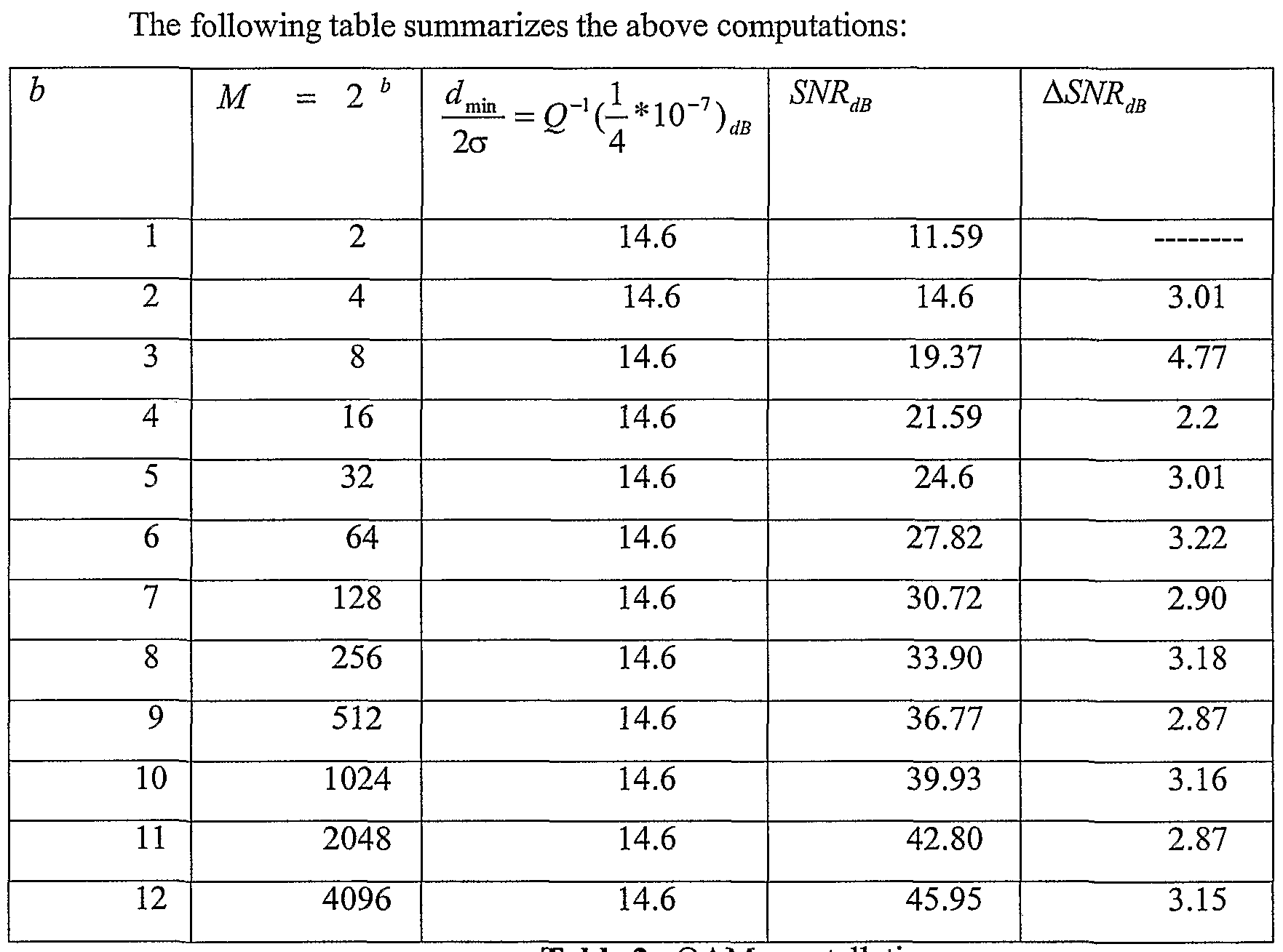
Bit loading is done such that probability of error is set sufficiently small, for example, 10"7 which is typical in ADSL systems. Table 1 illustrates the effect of constellation size (M ) on the symbol error rate of the QAM modulation. The values of d.
- for various M-QAM systems have been tabulated in Table 1.
2σ
After the equalization process, the DMT system maintains the minimum distance ( ^min ) to De aD0Ut the same over all the constellations. Thus, noise power is a sufficient criteria for monitoring the detection signal-to-noise ratio per sub-channel. As can be seen from this table, variation of noise power for various constellation sizes is negligible. As discussed with respect to the embodiment of Figure ID, estimation of noise power can be done by determining the power of the quantization or detection error 1 2 at a slicer, with the detection error 162 being the difference 168 between input 163 and output 165 of the slicer. The noise power of the subchannels can be stored in an array 144 in a memory accessible by the bit distribution module 150 (Figure 1C).
Table 1. M-QAM signal-to-noise ratio as a function of probability of error
Assuming that for an embodiment of the invention, bit loading is done such that the probability of error is set to 10~
7 (assuming zero dB margin) over all sub-channels, then the noise standard deviation can be estimated as follows:
σ .0942c
min
The probability of symbol error for M-ary modulation can be estimated from the following equation:
For a probability of error of 10
~7 the argument of Q function would be around 14.6 dB. Thus rl —
---mi£ - 10 20
2σ
The average energy of the QAM modulation can be computed from the following equations:
E = ™^ for b = log2 M even &M ≠ 2
Note that even and odd bits/sub-channel result in square and cross constellations accordingly. For the special case of M = 8 the energy can be estimated as follows:
Also for a one bit (two point) constellation the energy can be computed as
E = -d .
E_
Computing dmin as a function of average energy and knowing that SNR = - — - , the 2σ : signal-to-noise ratio for M-point QAM constellation with a probability of error of 10 7 can be estimated as follows:
M -\
SNR : *10 1.46 for b - log 2 M even
31
M - ^2_ 10 1.46
SNR = for έ = log2 odd & ≠ 8
SNR = 3 *10 46 for = 8
SNR = .5 *10' for M = 2
Table 2 QAM constellation energy
An example of such an incremental/decremental signal-to-noise ratio resource profile is shown in Table 3 below. In this example, for each sub-channel, there is computed the resulting change in the signal-to-noise ratio, ΔSΝR, resulting from increases in the bit allocation for both 1 and 2 bits and for decreases in the bit allocation of a sub-channel for both 1 and 2 bits.
Based on the above computations, the amount of increment/decrement in SΝR for various constellation sizes and for symbol probability of error of 10-7 can be summarized as follows:
Table 3
Table 3 would typically be used in an ADSL system such as those defined in ITU-T standards G.992.1 and G.992.2 which have maximum and minimum requirements with respect to the number of bits allowed per sub-channel. In the example shown in Table 3, the minimum number of bits per sub-channel requirement is 2 bits and the maximum number of bits per sub-channel requirement is 12 bits. As can be seen by the entries "Not allowed", sub-channels with two and three bit constellations, would be considered unused sub-channels by taking one or two bits respectively from these subchannels. Thus, the decremental signal-to-noise ratio for sub-channels with two bits should be zero. In another system of DMT modems that can support one bit (a two point) constellation, the values inside the parenthesis should be used instead. For the ADSL system with the two bit minimum requirement:
N
ΔSNR_,( = 0 where i e i = 0,1,...— ,\ b,
and
N
ΔSNR_2( = 0 where i e < = 0,l,...— ,\ b, = 3
In computing the incremental signal-to-noise ratio for unused bins in this embodiment, we assume that:
N
ΔSNR+2(z) = 0 where i e = 0,1,...— ,| bt = 0
In the above equation, i e < fi ~ 0,1,... — N ,| bi , = 01 refers to the set of unused sub-channels.
However, since they are already loaded with 2 bits, the incremental signal-to-noise ratio for those particular bins is zero.
Figure 2 shows an embodiment of an overall method 200 for performing bit swapping according to the present invention which may be embodied in part or in full as computer instructions embodied in a computer usable medium to be executed by a processor, such as a digital signal processor.
First, the SΝR for a given probability of error for each constellation size is computed 202. An example of such a computation is seen in Table 2. Then the change in SΝR, ΔSΝR+j and ΔSΝR-j for j = 1 to U bits to be swapped is computed 204 for each constellation size. For example as shown in Table 3 the incremental and decremental ΔSΝR for swapping 1 bit and 2 bits were computed. U = 2 in the example of Table 3.
Using the detection error power signal N; , compute 206 the noise power N? ,
N i = 1,2,3, — , for both the used and unused sub-channels, which m the embodiment of
2
Figure 1C are stored in a noise power array 144 in memory. Also stored in memory, is
an array of transmit scaling factors gt 2 , i = 1,2,3, — N , (see table 158 in Figure 1C). The average noise power Νm 2 over the used sub-channels is determined 208. For each subchannel^), compute 210 the postj bit increment SNR margin, hereafter referred to as the resource profile for j bit swapping. In the embodiment of Figure 2, the following equation is used:
/(/) - ASNR+ J(i) with = 1,2,3,— wherein/(i) is a resource function defined as i) = (Nm 2 - Ni 2) + (gmax 2 - gi 2).
The term gmax is the fixed maximum gain allowed for each sub-channel, and g; is the transmit gain for the ith sub-channel. An example of a range of gain settings is the range from -14.5dB to 2.5dB as recommended in ITU-T standard G992.2.
The most critical sub-channel is determined as the sub-channel having the maximum noise power, max(Nj2) of used sub-channels, and it is then identified 212 as the source sub-channel. Based upon the computed resource profile for j bit swapping, a candidate set of one or more destination sub-channels is determined 214 that will have the best resulting SNR for j bits swapped, or in other words, the one or more destination sub-channels that have the maximum post j bit increment SNR margin. If these subchannels are not selected correctly, the result can be a sub-optimum solution with considerable performance degradation.
Next, the scaling of the transmit gain factor is determined 216 for the source and I or destination sub-channels 216. Next, a request for bit swapping and/or adjusting of the transmit gain factors is sent 218 to the transmitter.
Figures 3A and 3B illustrate an embodiment of performing bit swapping in an ADSL system such as the one shown in Figures 1A, IB, 1C and ID. In this embodiment, the allocation of bits obeys maximum and minimum bits per sub-channel requirements of, 12 bits and 2 bits, respectively. Furthermore, up to two bits are allowed to be swapped between sub-channels in this example. The ΔSNR+i, ΔSNR], ΔSNR-2, ΔSNR+2 for the various constellation sizes in this example have been determined and stored in ΔSNR table 152 (Figure 1C).
The embodiment may be implemented entirely or in any combination of firmware, hardware, or in software executed by a processor such as a digital signal processor. Furthermore, the embodiment may be stored as instructions in a computer usable medium.
In the example of Figures 1A to ID, the bit distribution module 150 reads the noise power array 144 to determine which used sub-channel has the maximum noise power N;2. The sub-channel with the maximum noise power is the most critical subchannel and is identified as the source sub-channel 302. The average noise power over used sub-channels Nm 2 may be either computed at this point or was previously computed and stored in the array 144. The term gmax is the fixed maximum gain allowed for each sub-channel by the embodying system and can be stored in the gain table 158. Resource profiles for one bit swapping 304 and two bit swapping 306 are computed for the resource or power margin or SNR margin available per sub-channel. In this embodiment, the one bit swapping resource profile is computed 304 according to the following:
N ( -ΔSNR+,(z) with 1 = 1,2,3,— where/0) = (Νm 2-Ν,2) + (glrø 2 - g,2).
The bit distribution module 150 also determines 306 the two bit swapping resource profile according to the following:
f(j) - ΔSNR+ 2(1) with i = 1,2,3,^ where/(i) = (Νm 2 - N,2) + (gmax 2 - g,2).
A candidate set of destination sub-channels is determined 308 based upon which sub-channels will have the best resulting SNR margin after bit swapping as indicated by the resource profiles. Bits may be allocated to one or more destination sub-channels, so the candidate set may comprise one or more destination sub-channels. A sub-channel, which should not be the source sub-channel i ≠ s , that will have the maximum or best post 1-bit increment SNR margin (resource) without violating the maximum bits per sub-channel requirement b(i) < bmaκ - 1 , is selected as the first best 1 -bit destination sub-channel di as indicated by dx = arg, max/(z) - ΔSNR+1 (i) i ≠ s and b(i) ≤ bmm - 1.
Additionally, the best destination sub-channel for performing a 2-bit swap is selected 308. The destination is the sub-channel which has the maximum or best post 2- bit increment SΝR margin. The best 2-bit destination sub-channel is selected 308 in this embodiment as indicated by: d2 = arg, max/(z) - ΔSNR+2 (/) i ≠ s and b(i) ≤ έmax - 2.
The second best 1-bit destination sub-channel is selected 308 according to the same criteria from the set of sub-channels other than the source and first best 1-bit destination sub-channels as indicated by:
d3 = arg, max (t) - ΔSNR+1(z) and z' ≠ s and i ≠ dl and b(i) ≤ /3max - 1.
Which destination sub-channels in the candidate set of the first best 1-bit destination, the second best 1-bit destination and the best 2-bit destination sub-channels will be selected to receive bits depends on how the source sub-channel noise deterioration is to be compensated while obeying maximum and minimum bits per subchannel requirements.
The resource function for the source sub-channel is computed 310 to determine whether losing one-bit will be enough to compensate for the noise deterioration as indicated by f(s) + ASNR_l(s) ≥ 0. If one bit is enough to compensate for the deterioration, determine 312 whether the source sub-channel can lose a bit without violating the minimum bit requirement, and that the first best 1-bit destination sub-channel's resulting SΝR will be acceptable, for example will not become the most critical sub-channel, as indicated by satisfaction of the following: 0 < f(d ) - ΔSNR+1 (dl ) and b(s) ≠ 2.
Upon meeting the requirements, the bit swap request will be for 1 bit from subchannel s to the first best 1 -bit destination sub-channel c 314. Next new transmit gain factors for the first best 1-bit destination sub-channel dx and the source s sub-channel will be determined 318 according to the following. g (dl) = gM 2 ( i) + ^SNR+l(dl + (N -Nl) g = ώ -ΔSNR_1w+(Ns 2 -Nm 2)
The gains are readjusted so that the noise power in the source and destination sub-channels are about the average noise power N,, resulting in a uniform distribution of noise throughout the sub-channels.
A bit swap request is caused to be sent 319 to the transmitter to request that the bits be swapped accordingly and that the new transmit gain factors be applied to the source and destination sub-channels.
In the event that the best 1-bit destination sub-channel will have an unacceptable resulting SΝR or the loss of 1 -bit to the source-subchannel will violate the minimum bit requirement, then no bit swapping is performed and a new gain is calculated 316 for the source sub-channel according to the following: g s) = go 2,Λs) + Ns 2 'Nm 2 )
A bit swap request is caused to be sent 319 to the transmitter to request that the new transmit gain factor be applied to the source sub-channel.
In the event that one bit being removed is not enough to compensate the deterioration in the source sub-channel (f(s) + ASNR_1(s) ≥ 0 is not satisfied 310), then
it is determined 320 if the source sub-channel can lose two bits without violating the minimum two bit requirement and whether the best 2-bit destination sub-channel's resulting SNR will be acceptable as determined by satisfaction of the following:
0 < f(d2 ) - ASNR+2 (d2 ) and b(s) ≠ 3.
If the criteria is satisfied, then a bit swap request will be for 2 bits from subchannel s to best 2-bit destination sub-channel d2 322. Next, new transmit gain factors for the best 2-bit destination sub-channel di and the source s sub-channel will be determined 326 according to the following: g d2) = gM 2 (d2) + SNR+1(d2) + (Nl -N2) g ω = g M 2 - SXR-2 + w2 - N2 ).
A bit swap request is caused to be sent 319 to the transmitter to request that the bits be swapped accordingly and that the new transmit gain factors be applied to the source and destination sub-channels. However if an unacceptable SΝR would result for the best 2-bit destination subchannel or the minimum bit requirement would be violated, it will be determined 324 whether the best 1-bit destination sub-channel will have an acceptable resulting SΝR by taking on one more bit as indicated as follows:
If the resulting SΝR will be unacceptable as indicated by the above equation not being satisfied, then no bit swapping is performed, and a new gain is calculated 330 for the source sub-channel according to the following:
A bit swap request is caused to be sent 319 to the transmitter to request that the new transmit gain factor be applied to the source sub-channel.
However, upon satisfaction of the equation, it is determined whether the source sub-channel can lose two bits without violating the minimum bit requirement, and that the resulting SΝR of the second best 1-bit destination sub-channel d3 will be acceptable, for example will not become the most critical sub-channel, as indicated by satisfaction of the following 328:
0 < f(d 3 ) - ΔSNR+1 (d3 ) and b(s) ≠ 3.
If the above equation is satisfied, then a bit swap request for 2 bits from subchannel s with 1 bit to each of the 1-bit destination sub-channels ds and d3 will be formulated 334. Next, new gain values for the first best 1-bit destination sub-channel dh the second best 1-bit destination sub-channel d3 and the source subchannel s will be determined 338 according to the following: g idd = g2,Λdl) + ASNR÷l(dl) + (N2 ι -Nl) S ids ) = gM 2 (d3 ) + ΔSNR+1 (d3 ) + (Nl - N2 )
^ = ώ ω -ΔSNR_2 + (Ns 2 -N,2,).
A bit swap request is caused to be sent 319 to the transmitter to request that the bits be swapped accordingly and that the new transmit gain factors be applied to the source and destination sub-channels.
In the event that both 1-bit destination sub-channels will have resulting acceptable SΝRs, but the source sub-channel cannot lose two bits, a determination is made whether the source sub-channel can lose even 1 bit 332 as indicated. If the source can lose 1 bit, then the bit swap request will be for 1 bit from sub-channel s to first best 1-bit destination sub-channel d, 336. Next new gain values for the first best 1-bit destination sub-channel d, and the source 5 will be determined 340 according to the following. (
1) = g
2 ω(^.) + ΔSNR
+1(rf
1) + (^
1 -N
2)
A bit swap request is caused to be sent 319 to the transmitter to request that the bits be swapped accordingly and that the new transmit gain factors be applied to the source and destination sub-channels. In the event that the loss of 1-bit to the source-subchannel will violate the minimum bit requirement, then a new gain is calculated for the source sub-channel according to the following 330: g (s) = go 2 I(, (s) + (N; - Nm 2) .
A bit swap request is caused to be sent 319 to the transmitter to request that the new transmit gain factor be applied to the source sub-channel.
In the embodiment using ADSL modems as defined in G.992.1 and G.992.2, one of the ADSL Overhead Channels designated AOC, has AOC messages which can be carried in either the sync byte of the interleaved channel or the LEX byte of the
interleaved channel. An AOC message from the receiver to the transmitter consists of an eight-bit message header followed by several more bytes, depending on the type of message. One such message is the Bit Swap Request which signals a Normal bit swap to move one bit from one sub-channel to another, and an Extended Bit Swap Request which is used to move two bits from a sub-channel. This header allows for six message fields instead of four. In addition to requesting bit swaps, the Bit Swap Request Commands can be sent to adjust the transmitted power in a sub-channel (i.e. +ldB, -1 dB, -2 dB, +2 dB and +3 dB).
Therefore, using the proposed scheme, the DMT ADSL modem would track any unwanted variation of channel and noise condition. More specifically, the present invention as embodied for an ADSL system increases the robustness of ADSL modems by tracking and compensating the most critical sub-channels.
Figure 4 is a flowchart of an embodiment of a method for performing dynamic rate adjustment in an ADSL system such as the one shown in Figures 1A, IB, 1C and ID.
The embodiment may be implemented entirely or in any combination of firmware, hardware, or in software executed by a processor such as a digital signal processor. Furthermore, the embodiment may be stored as instructions in a computer usable medium. In the context of dynamic rate adjustment, the bit rate for the channel can be adjusted. For example, bits can be added to a sub-channel without being removed from another sub-channel. Similarly, bits can be removed from a sub-channel without the bits being transferred to another sub-channel.
In this embodiment, the source sub-channel is determined as the sub-channel having the maximum noise power, maxQSfi2) of the sub-channels as in the previous examples.
Next, it is determined 406 whether the noise power of the source sub-channel is acceptable for a desired result. An example of a desired result is maintaining a bit error rate. In the embodiment shown, the noise power is checked to see if it is within a predetermined threshold 406. If it is, then it is determined 410 whether there exists at least one destination sub-channel that can accept at least one more bit. In one embodiment, a set of one or more destination sub-channels can be determined in the same manner as in the bit swapping examples previously described. In the event that no destination sub-channel exists that can accept at least one more bit, then a new transmit
gain factor gy of the source sub-channel is deteπnined 424 to be communicated to the transmitter. For example, the communication can be accomplished by sending a message to the transmitter.
In the event that the noise power of the source sub-channel is within a predetermined threshold, and there exists a destination sub-channel that can accept at least one more bit, then determine 420 a number of bits to be added to the destination sub-channel based on the non-uniform incremental SNR margin for the destination subchannel to increase the bit rate. This number of bits to be added to the destination subchannel is communicated to the transmitter. In dynamic rate adjustment, the source sub- channel having a noise power within a predetermined threshold may have a SNR margin that allows it to accept one or more bits, so that the source sub-channel can be treated as a destination sub-channel to which bits will be added.
In the event that the noise power of the source sub-channel is not 408 within a predetermined threshold, then determine 416 whether there exists at least one destination sub-channel that can accept at least one more bit. In one embodiment, the destination sub-channel can be determined in the same manner as in the bit swapping examples previously described. In the event that a destination sub-channel does exist 414 that can accept at least one more bit, then perform 428 bit swapping. In one embodiment, bit swapping may be performed in the same manner as illustrated in the bit swapping examples previously described.
In the event that the noise power of the source sub-channel is not 408 within a predetermined threshold, and a destination sub-channel does not exist 422 that can accept at least one more bit, then determine 426 a number of bits to be removed from the source sub-channel based on the non-uniform decremental SNR margin for the source sub-channel to decrease the bit rate. The number of bits to be removed from the source sub-channel is communicated to the transmitter.
The foregoing description of the embodiments of the invention has been presented for the purposes of illustration and description. It is not intended to be exhaustive or to limit the invention to the precise form disclosed. Many modifications and variations are possible in light of the above teaching. It is intended that the scope of the invention be limited not by this detailed description, but rather by the claims appended hereto. What is claimed is: