WO2002015302A2 - Thermosetting composition for electrochemical cell components and methods of making thereof - Google Patents
Thermosetting composition for electrochemical cell components and methods of making thereof Download PDFInfo
- Publication number
- WO2002015302A2 WO2002015302A2 PCT/US2001/041713 US0141713W WO0215302A2 WO 2002015302 A2 WO2002015302 A2 WO 2002015302A2 US 0141713 W US0141713 W US 0141713W WO 0215302 A2 WO0215302 A2 WO 0215302A2
- Authority
- WO
- WIPO (PCT)
- Prior art keywords
- composite material
- thermosetting resin
- isoprene
- resin system
- butadiene
- Prior art date
Links
Classifications
-
- H—ELECTRICITY
- H01—ELECTRIC ELEMENTS
- H01M—PROCESSES OR MEANS, e.g. BATTERIES, FOR THE DIRECT CONVERSION OF CHEMICAL ENERGY INTO ELECTRICAL ENERGY
- H01M4/00—Electrodes
- H01M4/02—Electrodes composed of, or comprising, active material
- H01M4/64—Carriers or collectors
- H01M4/66—Selection of materials
- H01M4/668—Composites of electroconductive material and synthetic resins
-
- C—CHEMISTRY; METALLURGY
- C08—ORGANIC MACROMOLECULAR COMPOUNDS; THEIR PREPARATION OR CHEMICAL WORKING-UP; COMPOSITIONS BASED THEREON
- C08J—WORKING-UP; GENERAL PROCESSES OF COMPOUNDING; AFTER-TREATMENT NOT COVERED BY SUBCLASSES C08B, C08C, C08F, C08G or C08H
- C08J5/00—Manufacture of articles or shaped materials containing macromolecular substances
-
- H—ELECTRICITY
- H01—ELECTRIC ELEMENTS
- H01B—CABLES; CONDUCTORS; INSULATORS; SELECTION OF MATERIALS FOR THEIR CONDUCTIVE, INSULATING OR DIELECTRIC PROPERTIES
- H01B1/00—Conductors or conductive bodies characterised by the conductive materials; Selection of materials as conductors
- H01B1/20—Conductive material dispersed in non-conductive organic material
- H01B1/24—Conductive material dispersed in non-conductive organic material the conductive material comprising carbon-silicon compounds, carbon or silicon
-
- H—ELECTRICITY
- H01—ELECTRIC ELEMENTS
- H01M—PROCESSES OR MEANS, e.g. BATTERIES, FOR THE DIRECT CONVERSION OF CHEMICAL ENERGY INTO ELECTRICAL ENERGY
- H01M4/00—Electrodes
- H01M4/02—Electrodes composed of, or comprising, active material
- H01M4/64—Carriers or collectors
- H01M4/66—Selection of materials
- H01M4/665—Composites
- H01M4/666—Composites in the form of mixed materials
-
- H—ELECTRICITY
- H01—ELECTRIC ELEMENTS
- H01M—PROCESSES OR MEANS, e.g. BATTERIES, FOR THE DIRECT CONVERSION OF CHEMICAL ENERGY INTO ELECTRICAL ENERGY
- H01M8/00—Fuel cells; Manufacture thereof
- H01M8/02—Details
- H01M8/0202—Collectors; Separators, e.g. bipolar separators; Interconnectors
- H01M8/0204—Non-porous and characterised by the material
- H01M8/0221—Organic resins; Organic polymers
-
- H—ELECTRICITY
- H01—ELECTRIC ELEMENTS
- H01M—PROCESSES OR MEANS, e.g. BATTERIES, FOR THE DIRECT CONVERSION OF CHEMICAL ENERGY INTO ELECTRICAL ENERGY
- H01M8/00—Fuel cells; Manufacture thereof
- H01M8/02—Details
- H01M8/0202—Collectors; Separators, e.g. bipolar separators; Interconnectors
- H01M8/0204—Non-porous and characterised by the material
- H01M8/0223—Composites
- H01M8/0226—Composites in the form of mixtures
-
- C—CHEMISTRY; METALLURGY
- C08—ORGANIC MACROMOLECULAR COMPOUNDS; THEIR PREPARATION OR CHEMICAL WORKING-UP; COMPOSITIONS BASED THEREON
- C08J—WORKING-UP; GENERAL PROCESSES OF COMPOUNDING; AFTER-TREATMENT NOT COVERED BY SUBCLASSES C08B, C08C, C08F, C08G or C08H
- C08J2321/00—Characterised by the use of unspecified rubbers
-
- Y—GENERAL TAGGING OF NEW TECHNOLOGICAL DEVELOPMENTS; GENERAL TAGGING OF CROSS-SECTIONAL TECHNOLOGIES SPANNING OVER SEVERAL SECTIONS OF THE IPC; TECHNICAL SUBJECTS COVERED BY FORMER USPC CROSS-REFERENCE ART COLLECTIONS [XRACs] AND DIGESTS
- Y02—TECHNOLOGIES OR APPLICATIONS FOR MITIGATION OR ADAPTATION AGAINST CLIMATE CHANGE
- Y02E—REDUCTION OF GREENHOUSE GAS [GHG] EMISSIONS, RELATED TO ENERGY GENERATION, TRANSMISSION OR DISTRIBUTION
- Y02E60/00—Enabling technologies; Technologies with a potential or indirect contribution to GHG emissions mitigation
- Y02E60/10—Energy storage using batteries
-
- Y—GENERAL TAGGING OF NEW TECHNOLOGICAL DEVELOPMENTS; GENERAL TAGGING OF CROSS-SECTIONAL TECHNOLOGIES SPANNING OVER SEVERAL SECTIONS OF THE IPC; TECHNICAL SUBJECTS COVERED BY FORMER USPC CROSS-REFERENCE ART COLLECTIONS [XRACs] AND DIGESTS
- Y02—TECHNOLOGIES OR APPLICATIONS FOR MITIGATION OR ADAPTATION AGAINST CLIMATE CHANGE
- Y02E—REDUCTION OF GREENHOUSE GAS [GHG] EMISSIONS, RELATED TO ENERGY GENERATION, TRANSMISSION OR DISTRIBUTION
- Y02E60/00—Enabling technologies; Technologies with a potential or indirect contribution to GHG emissions mitigation
- Y02E60/30—Hydrogen technology
- Y02E60/50—Fuel cells
-
- Y—GENERAL TAGGING OF NEW TECHNOLOGICAL DEVELOPMENTS; GENERAL TAGGING OF CROSS-SECTIONAL TECHNOLOGIES SPANNING OVER SEVERAL SECTIONS OF THE IPC; TECHNICAL SUBJECTS COVERED BY FORMER USPC CROSS-REFERENCE ART COLLECTIONS [XRACs] AND DIGESTS
- Y02—TECHNOLOGIES OR APPLICATIONS FOR MITIGATION OR ADAPTATION AGAINST CLIMATE CHANGE
- Y02P—CLIMATE CHANGE MITIGATION TECHNOLOGIES IN THE PRODUCTION OR PROCESSING OF GOODS
- Y02P70/00—Climate change mitigation technologies in the production process for final industrial or consumer products
- Y02P70/50—Manufacturing or production processes characterised by the final manufactured product
Definitions
- This invention relates to conductive materials, and in particular to conductive thermosetting compositions which find particular utility in the manufacture of electrochemical cell components, and methods of making thereof.
- a preferred type of electrochemical cell is the "proton exchange membrane" cell, wherein the cathode of the cell is separated from the anode by a proton exchange membrane that facilitates the diffusion of ions and/or water between the cathode and anode.
- the typical electrochemical cell includes a number of individual cells arranged in a stack, with the working fluid directed through the cells via input and output conduits formed within the stack structure. The cells within the stack are sequentially arranged, each including a cathode, a proton exchange membrane, and an anode.
- MEAs Membrane electrode assemblies
- the MEA for each cell is placed between a pair of electrically conductive elements which serve as current collectors for the anode/cathode, and which generally contain an array of grooves in the faces thereof for distributing the gaseous reactants (H 2 and O 2 /air) over the surfaces of the anode and cathode.
- the gaseous O 2 /air reactant is usually saturated, typically with water.
- Electrochemical cell systems generally comprise a plurality of such cells, which are stacked together in electrical series separated from each other by an impermeable, electrically conductive plate referred to as a bipolar plate.
- the bipolar plate thus serves as an electrically conductive separator element between two adjacent cells, and generally also has reactant gas distributing grooves on both external faces thereof. In most cases the bipolar plate also has internal passages through which coolant flows to remove heat from the stack.
- the exterior faces of the bipolar plates are in constant contact with often highly corrosive, acidic solutions at elevated temperatures.
- at least one of the electrode faces may be polarized in the presence of pressurized, saturated air or hydrogen.
- Bipolar plates To survive in such an environment, the bipolar plates must be able to withstand these pressures and be highly resistant to corrosion and degradation. Bipolar plates are often fabricated from graphite, which is lightweight, corrosion resistant, and electrically conductive. However, graphite is quite brittle and thus prone to cracking, and mechanically difficult to handle, thus increasing production costs. Additionally, graphite is porous, making it virtually impossible to make the very thin, gas-impervious plates that are desirable for low- weight, low- volume electrochemical cell stacks. The graphite plates must also be operably connected to the other components by seal rings. Typically the seal ring material contains plasticizers and additives that leach out over time and contaminate the catalyst, which generally halts energy production.
- Wilson et al., and U.S. Patent No. 6,251,308 to Butler disclose molding compositions with conductive fillers that can be formed into structures exhibiting electrical and thermal conductivity such as bipolar plates.
- the molding compositions typically employ a low viscosity resin system, specifically epoxy, epoxy vinyl ester, and phenolic resin systems. While these compositions may offer some improvements to electrochemical cell technology, they may not have sufficient long-term chemical resistance. Materials employed in the electrochemical cell must be resistant to degradation in a particularly punishing environment over periods of time measured in years. Accordingly, there is a perceived need in the art for a low cost, conductive molding composition with a high chemical resistance for use in electrochemical cells and methods of making thereof.
- thermosetting resin composition comprises: (1) a polybutadiene or polyisoprene resin; (2) an optional, functionalized liquid polybutadiene or polyisoprene resin; (3) an optional butadiene- or isoprene-containing copolymer; and (4) an optional low molecular weight polymer.
- the conductive moldable composite material is used to form a bipolar plate, current collector or other electrochemical cell component.
- articles made of the conductive, moldable composite material are resistant to chemical attack and hydrolysis, have excellent mechanical strength and toughness, have a volume resistivity of about 0.116 ohm-cm or less, and have a thermal conductivity of at least about 5 watts/meter °K (W/m°K).
- Articles have a linear shrinkage per unit length of the molded composite in the X-Y plane less than or equal to about 0.005, measured as described in ASTM D-955.
- the conductive, moldable composite material as well as articles made from it are economical to produce due to the inexpensive starting materials as well as the use of conventional processing equipment.
- a conductive, moldable composite material for the manufacture of electrochemical cell components comprises a thermosetting resin system and conductive filler wherein the thermosetting resin composition comprises: (1) a polybutadiene or polyisoprene resin; (2) an optional, functionalized liquid polybutadiene or polyisoprene resin; (3) an optional butadiene- or isoprene-containing polymer; and (4) an optional, low molecular weight polymer.
- the conductive moldable composite material is used to form a bipolar plate, current collector or other electrochemical cell component.
- the resin system used to form the conductive, moldable composite material is a thermosetting composition generally comprising a polybutadiene resin, polyisoprene resin or mixture thereof.
- the polybutadiene or polyisoprene resins may be liquid or solid at room temperature.
- Liquid resins may have a molecular weight greater than 5,000, but preferably have a molecular weight of less than 5,000 (most preferably between 1,000 and 3,000).
- the preferably liquid (at room temperature) resin portion maintains the viscosity of the composition at a manageable level during processing to facilitate handling, and it also crosslinks during cure.
- Polybutadiene and polyisoprene resins having at least 90% 1,2-addition by weight are preferred because they exhibit the greatest crosslink density upon cure owing to the large number of pendant vinyl groups available for crosslinking. High crosslink densities are desirable because the products exhibit superior performance in an electrochemical cell environment at elevated temperatures.
- a preferred resin is B3000 resin, a low molecular weight polybutadiene liquid resin having greater than 90 weight percent (wt.%) 1,2-addition.
- B3000 resin is commercially available from Nippon Soda Co., Ltd.
- the resin system used to form the conductive, moldable composite optionally comprises functionalized liquid polybutadiene or polyisoprene resins.
- functionalized liquid polybutadiene or polyisoprene resins include but are not limited to epoxy, maleate, hydroxy, carboxyl and methacrylate.
- useful liquid butadiene copolymers are butadiene-co-styrene and butadiene-co-acrylonitrile.
- Possible functionalized liquid polybutadiene resins include Nisso G-1000, G-2000, G- 3000; Nisso C-1000; Nisso BN-1010, BN-2010, BN-3010, CN-1010; Nisso TE-2000; and Nisso BF-1000 commercially available from Nippon Soda Co., Ltd. and Ricon 131/MA commercially available from Colorado Chemical Specialties, hie.
- the optional, butadiene- or isoprene-containing polymer is preferably unsaturated and can be liquid or solid. It is preferably a solid, thermoplastic elastomer comprising a linear or graft-type block copolymer having a polybutadiene or polyisoprene block, and a thermoplastic block that preferably is styrene or omethyl styrene.
- Possible block copolymers e.g., styrene-butadiene-styrene tri-block copolymers, include Vector 8508M (commercially available from Dexco Polymers, Houston, TX), Sol-T-6302 (commercially available from Enichem Elastomers American, Houston, TX), and Finaprene 401 (commercially available from Fina Oil and Chemical Company, Dallas, TX).
- the copolymer is a styrene- butadiene di-block copolymer, such as Kraton Dl 118X (commercially available from Shell Chemical Corporation).
- Kraton Dl 118X is a di-block styrene-butadiene copolymer containing 30 vol% styrene.
- the butadiene- or isoprene-containing polymer may also contain a second block copolymer similar to the first except that the polybutadiene or polyisoprene block is hydrogenated, thereby forming a polyethylene block (in the case of polybutadiene) or an ethylene-propylene copolymer (in the case of polyisoprene).
- a polyethylene block in the case of polybutadiene
- an ethylene-propylene copolymer in the case of polyisoprene
- a preferred material is Kraton GX1855 (commercially available from Shell Chemical Corp.), which is believed to be a mixture of styrene-high 1 ,2 butadiene-styrene block copolymer and styrene-(ethylene-propylene)-styrene block copolymer.
- the butadiene- or isoprene-containing polymer comprises a solid thermoplastic elastomer block copolymer having the
- composition may further include a second thermoplastic elastomer block
- copolymer having the formula W p (Z-W) q (linear copolymer) or (graft copolymer) where Z is a polyethylene or ethylene-propylene copolymer block, W is a thermoplastic block, and p and q represent the average block numbers in the copolymer, p being 0 and 1 and q being at least 1.
- the volume to volume ratio of the polybutadiene or polyisoprene resin to butadiene- or isoprene-containing polymer preferably is between 1 :9 and 9:1, inclusive.
- the selection of the butadiene- or isoprene-containing polymer depends on chemical and hydrolysis resistance as well as the toughness conferred upon the molded material.
- the optional low molecular weight polymer resin is generally employed to enhance toughness and other desired characteristics of composition.
- suitable low molecular weight polymer resins include, but are not limited to, telechelic polymers such as polystyrene, multifunctional acrylate monomers and ethylene propylene diene monomer (EPDM) containing varying amounts of pendant norbornene groups and/or unsaturated functional groups.
- EPDM ethylene propylene diene monomer
- the optional low molecular weight polymer resin can be present in amounts of about 0 to about 30 wt% of the resin composition.
- Monomers with vinyl unsaturation may also be included in the resin system for specific property or processing conditions, such as to decrease the viscosity of the conductive moldable composite material, especially with high filler loading. Viscosity is a key factor in obtaining acceptable molding rheologies. Inclusion of one or more monomers with vinyl unsaturation has the added benefit of increasing crosslink density upon cure. Suitable monomers must be capable of co-reacting with one of the other resin system components.
- Suitable monomers include styrene, vinyl toluene, divinyl benzene, triallylcyanurate, diallylphthalate, and multifunctional acrylate monomers (such as Sartomer compounds available from Arco Specialty Chemicals Co.), among others, all of which are commercially available.
- the useful amount of monomers with vinyl unsaturation is about 0% by weight to about 80% by weight of the resin composition and preferably about 3% to about 50%.
- a curing agent is preferably added to the resin system to accelerate the curing reaction.
- the curing agent decomposes to form free radicals, which then initiate cross linking of the polymeric chains.
- Preferred curing agents are organic peroxides such as Luperox, dicumyl peroxide, t-butyl perbenzoate, 2,5-dimethyl-2,5-di(t-butyl peroxy)hexane, ⁇ , ⁇ '-bis(t-butyl peroxy)diisopropylbenzene, and 2,5-dimethyl-2,5-di(t-butyl peroxy) hexyne-3, all of which are commercially available. They may be used alone or in combination.
- Typical amounts of curing agent are from about 1.5 part per hundred parts of the total resin composition (PHR) to about 6 PHR.
- Useful conductive fillers include metal fillers that do not leach, thus poisoning the catalyst, for example pure nickel (Ni), or 316 stainless steel.
- Carbonaceous conductive fillers are preferred due to their resistance to acid environments. Examples of carbonaceous fillers are carbon fibers, coke, natural and synthetic graphite powder, vapor grown carbon fibers, carbon nanotubes, carbon microtubes, carbon black, and chemically modified, e.g., coated carbon black with enhanced electrical properties. These fillers may be used alone or in combination. Combinations of filler may be desirable to maximize the packing density of the filler and thereby maximize the electrical conductivity of the molded composite.
- Useful amounts of filler are about 10% to about 90% by volume of the total conductive molding composite material. Alternately useful amounts of filler are about 19.5 weight percent (wt%) to about 95.0 weight percent (wt%), preferably about 50 to about 95 wt%, more preferably about 80 to about 95 wt% based on the total weight of the conductive molding composite material.
- the fillers may have varying particle shapes, sizes and purities.
- some or all of the filler is in the form of fibers, microtubes, single wall or multi- wall graphite, single wall or multi-wall carbon nanotubes, platelets, or combinations comprising at least one of the foregoing filler forms.
- Fibers are herein defined as particles having a length to diameter ratio of at least about 2, preferably at least about 5 and more preferably at least about 100. Fibers having a length to diameter ratio of at least about 400 to about 10,000, which are known as high aspect ratio fillers, are preferred.
- Nanotubes and microtubes are exemplary high aspect ratio fillers.
- Platelets are herein defined as particles having two dimensions which are greater that a third dimension by at least a factor of two, preferably by greater than a factor of five. For example, the width and length are each at least two times greater than the height, or the diameter of a disk-shaped particle is at least two times greater than the height. Platelets may have regular or irregular geometries. Use of filler comprising fiber and/or platelets helps to decrease the amount of shrinkage of the composite material during cure. Particles wherein the longest single linear dimension is about 0.2 to 6000 micrometers may be used.
- the conductive moldable composite material may further include various other additives for improving thermal conductivity, impact properties, mold-release properties, and thermo-oxidative stability. These additives are generally non- electrically conductive. Thermal conductivity can be improved with the addition of metal oxides, nitrides, carbonates or carbides (hereinafter sometimes referred to as "ceramic additives"). Such additives can be in the form of powders, flakes or fibers. Exemplary materials include oxides, carbides, carbonates, and nitrides of tin, zinc, copper, molybdenum, calcium, titanium, zirconium, boron, silicon, yttrium, aluminum or magnesium; mica; glass ceramic materials; or fused silica. When present, the thermally conducting materials are preferably present between about 60 to about 200 parts of thermally conducting material per 100 parts of total resin ("PHR"), and more preferably about 80 to about 180 PHR. The amounts of the above additives should not impair molding operations.
- PHR total resin
- the conductive molding composite material is processed as follows. First, all the components (the resin system, curing agent, filler and a volatile solvent when used) are thoroughly mixed in conventional mixing equipment. The mixing temperature is regulated to avoid substantial decomposition of the curing agent (and thus premature cure). Additionally, a small amount of an inhibitor, about 50 to about 350 parts per million by weight of resin, may be added to protect against peroxide , decomposition. Mixing continues until the filler is uniformly dispersed tlirough the resin. Additional solvent may be added to facilitate the formation of small particles.
- the homogenized mixture is then removed, cooled and dried. If necessary the material may be deagglomerated by passing it through a coarse screen. Next, the particles are poured, pressed or injected into a mold, such as a compression, injection or transfer mold. Compression molding is preferred when some or all of the filler is in the form of fibers and or platelets. Without being bound by theory, it is believed that the filler particles can become oriented during compression molding which reduces shrinkage of the composite material during cure. Alternatively, an extruder is used and the material is molded into the desired shape. The shaped article is cured in either a one or two step cure process.
- the first step is a conventional peroxide cure step; typical cure temperatures are between about 150°C and about 200°C. If the method used to form the conductive moldable composite material into the desired shape heats the article to a temperature between about 150°C and about 200°C, then the forming step also constitutes the first cure step. Compression molding is one method of forming an article from the conductive moldable composite material which also functions as the first cure step.
- the second step of the cure process can either be a high temperature cure or high-energy electron beam irradiation cure (E-beam cure).
- a high temperature cure comprises heating the article to temperatures greater than about 230°C but less than the decomposition temperature of the material, generally about 400 °C under an inert atmosphere.
- E-beam curing is advantageous because it allows for controlled curing for a given system.
- the amount of curing (cross linking) is controlled by the total amount of radiation given to the article.
- the ability of the high-energy electrons to penetrate through the sample to specific depth is known as the penetration depth.
- the penetration depth is controlled by the E-beam source, and different sources give different penetration depths.
- the combined flexibility in the amount of curing as well as the depth of curing allows the production of articles with a range of physical dimensions, in particular thickness, as well as physical properties from the same conductive moldable composite material.
- Articles made of the conductive moldable composite material are resistant to chemical attack and hydrolysis, and have excellent mechanical strength and toughness.
- the articles preferably have a volume resistivity of about 0.116 ohm-cm or less, preferably about 0.08 ohm-cm or less and most preferably about 0.045 ohm- cm or less.
- the articles further possess a thermal conductivity of at least about 5 watts/meter °K, preferably at least about 7 watts/meter °K and more preferably at least about 9 watts/meter °K.
- linear shrinkage per unit length of the molded composite in the X-Y plane is less than or equal to about 0.005, preferably less than or equal to about 0.003, and most preferably less than or equal to about 0.001.
- Linear shrinkage per unit length of the molded composite is defined by ASTM D-955. Generally speaking it is the amount of shrinkage either in length (Y-direction) or width (X-direction) versus the corresponding original part dimension.
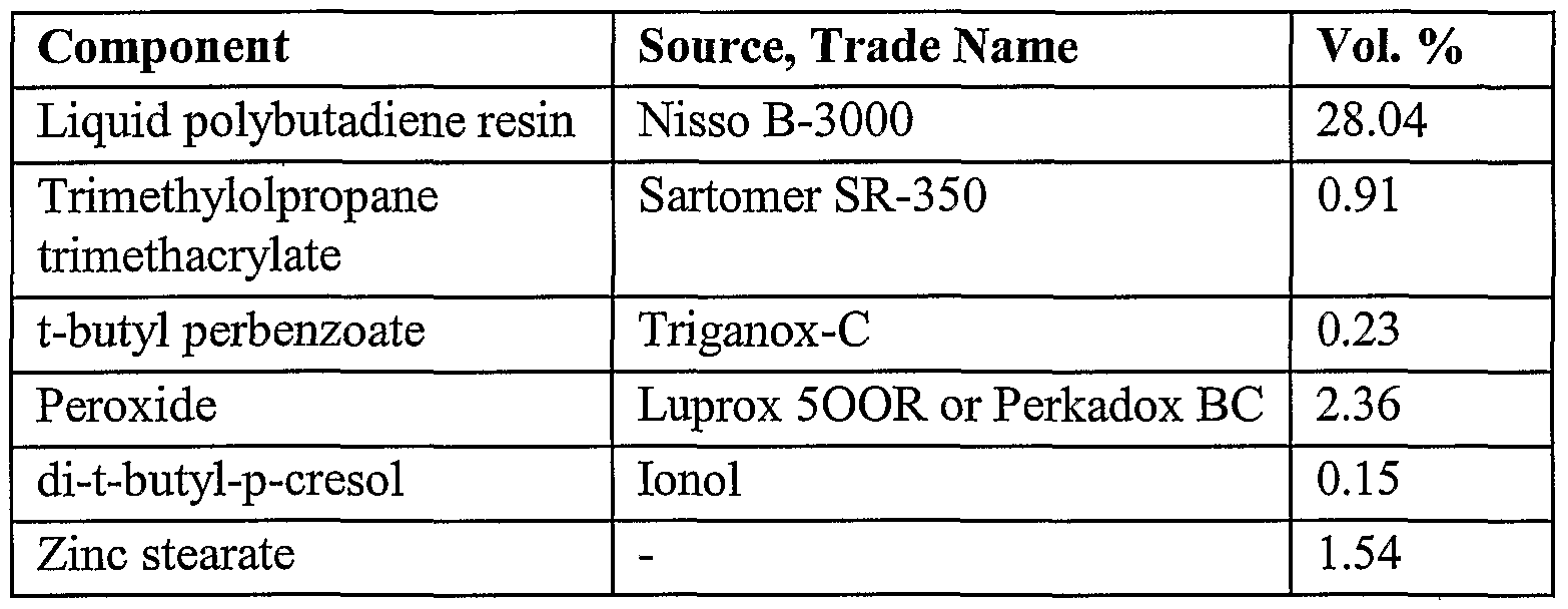
- the conductive moldable composite materials of the following examples were made using the formulation and components in Table 1 with the type of graphite varied by example. The resulting properties and graphite types are shown in Table 2.
- a dilute resin solution comprising up to about 50 parts by weight resin composition, preferably up to about 25 parts by weight resin composition and more preferably up to about 10 parts by weight resin composition and a volatile solvent, preferably acetone, was slowly added to the monomer, peroxides and inhibitor in a Ross double planetary mixer and mixed to produce a homogeneous solution. (Other volatile solvents may also be used.) Zinc stearate, a mold release agent, was then added and thoroughly mixed into the solution. The solution was added incrementally to the carbon fibers and graphite and mixed until all filler was completely dispersed. Another 100 parts by weight of acetone was added and the mixture was mixed for 15 minutes. The resulting particulate material was removed from the mixer and spread on screens and allowed to dry at room temperature. Residual solvent was removed in a drying oven at 120°C. The material was then passed through a coarse screen.
- a volatile solvent preferably acetone
- the material was molded into disks about 2 inches (50 mm) in diameter with a thickness of about 0.125 inch (3.18 mm) by compression molding at 180°C for four minutes. The disks were further cured in an oven at 240°C. The disks were tested for resistivity according to TPC-TM-650, flex stress and flex modulus according to ASTM D-790-99, and thermal conductivity according to ASTM C-518. Values for flex stress are given in pounds per square inch (psi) and megapascals (MPa). Values for flex modulus are given in kilopounds per square inch (Kpsi) and megapascals (MPa).
- Example 1 when further comprising NZ33, a neoalkoxy zirconate produced by Kenrich Petrochemicals, Inc., as a coupling agent, has a maximum stress of 2366 psi (16.3 Mpa) and a flex modulus of 1140 Kpsi (7862 Mpa).
- Examples 1-8 employ various kinds of graphites. These graphites can be differentiated primarily on the basis of their origin, carbon content, particle size, and purity.
- Asbury APS is a synthetic graphite with a minimum carbon content of 95% and mean particle size of 35 micrometers.
- Asbury 4012 is a synthetic graphite with a minimum carbon content of 98% and a mean particle size of 140 micrometers, and
- Asbury A60 is a synthetic graphite with a minimum carbon content of 98% and a mean particle size of 65 micrometers.
- Asbury A99 is a synthetic graphite with a minimum carbon content of 98% and a mean particle size of 25 micrometers
- Asbury A230U is a natural graphite with a very high carbon content and a mean particle size of 20 micrometers
- Asbury 4957 is a hybrid graphite with a minimum carbon content of 99%> and a mean particle size of 44 micrometers.
- Asbury 3610 is a natural flake graphite with a minimum carbon content of 99.5% and a mean particle size of 75 micrometers.
- Asbury 3621 is also a natural graphite plate with minimum carbon content of 99.4% and a mean particle size of 300 micrometers.
- the conductive moldable composite materials of the following examples were made using the formulation and components in Table 3 with the type of filler varied by example.
- the filler types and resulting properties are shown in Table 4 and Table 5.
- a dilute resin solution comprising up to about 50 parts by weight resin, preferably up to about 25 parts by weight resin and more preferably up to about 10 parts by weight resin and a volatile solvent, preferably acetone, is slowly added to the monomer, peroxides and inhibitor in a Ross double planetary mixer and mixed to produce a homogeneous solution.
- Zinc stearate, a mold release agent is then added and thoroughly mixed into the solution.
- the solution is added incrementally to the filler and mixed until all filler is completely dispersed.
- Another 100 parts by weight of acetone is added and the mixture is mixed for 15 minutes.
- the resulting particulate material is removed from the mixer and spread on screens and allowed to dry at room temperature. Residual solvent is removed in a drying oven at 120°C.
- the material is then passed through a coarse screen.
- the material was molded into rectangles about 4.21 inches (107 mm) long, 1.76 inches (44.7 mm) wide and 0.2 inches (5 mm) thick by compression molding at 180°C for four minutes.
- the rectangles were further cured in an oven at 240°C.
- the rectangles were checked for shrinkage using ASTM D-955 in the X and Y directions (width and length) and the coefficient of thermal expansion (CTE) was determined at a temperature range from 30°C to 145°C in both the X and Y directions according to ASTM D-696. Shrinkage is reported as linear shrinkage per unit length of the molded composite.
- Example 9 is a control example that contains no fiber or platelets
- Example 9 contains no fiber or platelets.
- Example 9 The comparison of the results of Examples 10-14 with Example 9 demonstrates the value of fibrous and platelet fillers in the composite material.
- the amount (weight percent based on the total weight of the composite material) of filler is kept constant at 84 wt% while the composition of the filler is varied.
- Asbury A99 is used exclusively.
Abstract
Description


Claims

Priority Applications (3)
| Application Number | Priority Date | Filing Date | Title |
|---|---|---|---|
| GB0305798A GB2383892B (en) | 2000-08-14 | 2001-08-14 | Thermosetting composition for electrochemical cell components and methods of making thereof |
| AU2001285436A AU2001285436A1 (en) | 2000-08-14 | 2001-08-14 | Thermosetting composition for electrochemical cell components and methods of making thereof |
| DE10196589T DE10196589T1 (en) | 2000-08-14 | 2001-08-14 | Thermosetting composition for components of an electrochemical cell and method for their production |
Applications Claiming Priority (4)
| Application Number | Priority Date | Filing Date | Title |
|---|---|---|---|
| US22515800P | 2000-08-14 | 2000-08-14 | |
| US60/225,158 | 2000-08-14 | ||
| US26415001P | 2001-01-25 | 2001-01-25 | |
| US60/264,150 | 2001-01-25 |
Publications (2)
| Publication Number | Publication Date |
|---|---|
| WO2002015302A2 true WO2002015302A2 (en) | 2002-02-21 |
| WO2002015302A3 WO2002015302A3 (en) | 2003-01-23 |
Family
ID=26919350
Family Applications (1)
| Application Number | Title | Priority Date | Filing Date |
|---|---|---|---|
| PCT/US2001/041713 WO2002015302A2 (en) | 2000-08-14 | 2001-08-14 | Thermosetting composition for electrochemical cell components and methods of making thereof |
Country Status (5)
| Country | Link |
|---|---|
| US (1) | US6811917B2 (en) |
| AU (1) | AU2001285436A1 (en) |
| DE (1) | DE10196589T1 (en) |
| GB (1) | GB2383892B (en) |
| WO (1) | WO2002015302A2 (en) |
Cited By (4)
| Publication number | Priority date | Publication date | Assignee | Title |
|---|---|---|---|---|
| WO2004008565A2 (en) * | 2002-07-10 | 2004-01-22 | E.I. Du Pont Canada Company | Elastomeric separator plates and method of fabrication |
| EP2065957A1 (en) * | 2006-07-31 | 2009-06-03 | SEIKOH GIKEN Co., Ltd. | Process for producing separator for fuel cell and separator for fuel cell |
| CN110943215A (en) * | 2019-05-31 | 2020-03-31 | 宁德时代新能源科技股份有限公司 | Lithium ion secondary battery |
| CN111180737A (en) * | 2019-05-31 | 2020-05-19 | 宁德时代新能源科技股份有限公司 | Lithium ion secondary battery, battery cell and negative pole piece |
Families Citing this family (16)
| Publication number | Priority date | Publication date | Assignee | Title |
|---|---|---|---|---|
| DE60205105T2 (en) * | 2001-05-14 | 2006-04-20 | Huntsman Advanced Materials (Switzerland) Gmbh | MOLD FOR THE PRODUCTION OF BIPOLAR PLATES |
| US20030157394A1 (en) * | 2002-02-20 | 2003-08-21 | Yuji Kohara | Energy converting polar plate device and method for the preparation thereof |
| US20040062974A1 (en) * | 2002-07-09 | 2004-04-01 | Abd Elhamid Mahmoud H. | Separator plate for PEM fuel cell |
| JP2005197222A (en) * | 2003-12-12 | 2005-07-21 | Nisshinbo Ind Inc | Fuel cell separator |
| US20050242471A1 (en) * | 2004-04-30 | 2005-11-03 | Bhatt Sanjiv M | Methods for continuously producing shaped articles |
| US20060293434A1 (en) * | 2004-07-07 | 2006-12-28 | The Trustees Of The University Of Pennsylvania | Single wall nanotube composites |
| KR101256792B1 (en) | 2005-07-20 | 2013-04-19 | 에이전시 포 사이언스, 테크놀로지 앤드 리서치 | Electroconductive curable resins |
| EP1947722B1 (en) * | 2005-11-09 | 2012-05-16 | DIC Corporation | Process for production of fuel cell separators and fuel cells comprising such separators |
| US8030376B2 (en) | 2006-07-12 | 2011-10-04 | Minusnine Technologies, Inc. | Processes for dispersing substances and preparing composite materials |
| WO2009111356A1 (en) * | 2008-03-02 | 2009-09-11 | Igt | Regulated gaming trusted energy saving |
| CN104136660A (en) | 2012-01-05 | 2014-11-05 | 巴伊材料公司 | Electrochemical methods and products |
| CN109792075A (en) | 2016-08-05 | 2019-05-21 | 阿姆泰克研究国际公司 | Composite porous and relevant device, method and the purposes of cured, suitable type |
| JP6922731B2 (en) * | 2017-12-27 | 2021-08-18 | トヨタ自動車株式会社 | Electrode manufacturing method |
| US11374227B2 (en) | 2018-02-02 | 2022-06-28 | Amtek Research International Llc | Dry process electrically conductive composite formation |
| DE102019209776A1 (en) * | 2019-07-03 | 2021-01-07 | Robert Bosch Gmbh | Bipolar plate for a fuel cell, method for manufacturing a bipolar plate for a fuel cell and fuel cell |
| JP7393279B2 (en) * | 2020-03-31 | 2023-12-06 | 日鉄ケミカル&マテリアル株式会社 | Conductive resin composition and electromagnetic shielding material using the composition |
Citations (3)
| Publication number | Priority date | Publication date | Assignee | Title |
|---|---|---|---|---|
| GB1264741A (en) * | 1969-04-01 | 1972-02-23 | ||
| EP0109824A1 (en) * | 1982-11-17 | 1984-05-30 | Kabushiki Kaisha Meidensha | Electrically conductive plastic complex material |
| EP0297888A1 (en) * | 1987-07-02 | 1989-01-04 | Lion Corporation | Electroconductive resin composition |
Family Cites Families (62)
| Publication number | Priority date | Publication date | Assignee | Title |
|---|---|---|---|---|
| US3012086A (en) | 1957-07-17 | 1961-12-05 | Allis Chalmers Mfg Co | Fuel cell |
| US3188242A (en) | 1959-01-22 | 1965-06-08 | Union Carbide Corp | Fuel cell battery containing flat carbon electrodes |
| US3134697A (en) | 1959-11-03 | 1964-05-26 | Gen Electric | Fuel cell |
| NL257579A (en) | 1959-11-03 | 1900-01-01 | ||
| US3497389A (en) | 1964-10-20 | 1970-02-24 | Mc Donnell Douglas Corp | Ion exchange membrane and fuel cell containing same |
| CA1051512A (en) | 1973-05-23 | 1979-03-27 | Royce E. Biddick | Bipolar electrode using electrically conductive plastic substrate containing vitreous carbon |
| US4175165A (en) | 1977-07-20 | 1979-11-20 | Engelhard Minerals & Chemicals Corporation | Fuel cell system utilizing ion exchange membranes and bipolar plates |
| US4265727A (en) | 1979-10-22 | 1981-05-05 | Hitco | Composite electrodes |
| US4545926A (en) * | 1980-04-21 | 1985-10-08 | Raychem Corporation | Conductive polymer compositions and devices |
| US4610808A (en) | 1982-07-19 | 1986-09-09 | Mitech Corporation | Conductive resinous composites |
| US4938833A (en) | 1982-09-30 | 1990-07-03 | Engelhard Corporation | Process for making film-bonded fuel cell interfaces |
| US4572813A (en) | 1983-09-06 | 1986-02-25 | Nikkiso Co., Ltd. | Process for preparing fine carbon fibers in a gaseous phase reaction |
| US4575432A (en) | 1984-07-09 | 1986-03-11 | W. R. Grace & Co. | Conductive thermosetting compositions and process for using same |
| US4565684A (en) | 1984-08-20 | 1986-01-21 | General Motors Corporation | Regulation of pyrolysis methane concentration in the manufacture of graphite fibers |
| US4663230A (en) | 1984-12-06 | 1987-05-05 | Hyperion Catalysis International, Inc. | Carbon fibrils, method for producing same and compositions containing same |
| US5165909A (en) | 1984-12-06 | 1992-11-24 | Hyperion Catalysis Int'l., Inc. | Carbon fibrils and method for producing same |
| JPS61296067A (en) * | 1985-06-24 | 1986-12-26 | Toshiba Chem Corp | Electrically-conductive resin composition |
| JPH0621213B2 (en) * | 1985-12-12 | 1994-03-23 | 出光石油化学株式会社 | Conductive polymer composition |
| JPS63213534A (en) | 1987-03-02 | 1988-09-06 | Inoue Mtp Co Ltd | Electrically conductive polymer composite material and production thereof |
| US5223568A (en) | 1987-05-14 | 1993-06-29 | Rogers Corporation | Process for forming hard shaped molded article of a cross-linked liquid polybutadiene or polyisoprene resin and a butadiene or isoprene containing solid polymer and resulting articles |
| US5194307A (en) | 1988-02-08 | 1993-03-16 | Martin Processing, Inc. | High performance epoxy based coverlay and bond fly adhesive with heat activated cure mechanism |
| CA1334479C (en) | 1988-08-29 | 1995-02-21 | Minoru Yoshinaka | Conductive composition and method for making the same |
| US4885457A (en) | 1988-09-30 | 1989-12-05 | Raychem Corporation | Method of making a conductive polymer sheet |
| US4988583A (en) | 1989-08-30 | 1991-01-29 | Her Majesty The Queen As Represented By The Minister Of National Defence Of Her Majesty's Canadian Government | Novel fuel cell fluid flow field plate |
| US5024818A (en) | 1990-10-09 | 1991-06-18 | General Motors Corporation | Apparatus for forming carbon fibers |
| US5830326A (en) | 1991-10-31 | 1998-11-03 | Nec Corporation | Graphite filaments having tubular structure and method of forming the same |
| AU3975793A (en) | 1992-04-03 | 1993-11-08 | Thermoset Plastics, Inc. | Conductor-filled thermosetting resin |
| US5272017A (en) | 1992-04-03 | 1993-12-21 | General Motors Corporation | Membrane-electrode assemblies for electrochemical cells |
| US5352289A (en) | 1992-12-18 | 1994-10-04 | Cabot Corporation | Low ash carbon blacks |
| US5591382A (en) | 1993-03-31 | 1997-01-07 | Hyperion Catalysis International Inc. | High strength conductive polymers |
| IT1270878B (en) * | 1993-04-30 | 1997-05-13 | Permelec Spa Nora | IMPROVED ELECTROCHEMISTRY CELL USING ION EXCHANGE MEMBRANES AND METAL BIPOLAR PLATES |
| DE4332014A1 (en) | 1993-09-21 | 1995-03-23 | Basf Lacke & Farben | Electrocoating lacquers and methods for lacquering electrically conductive substrates |
| DE4498933C2 (en) | 1993-11-19 | 2000-03-02 | Japan Chemical Engineering & M | Benzylated lignocellulosic material and a method of production thereof |
| US5527363A (en) | 1993-12-10 | 1996-06-18 | Ballard Power Systems Inc. | Method of fabricating an embossed fluid flow field plate |
| TW324737B (en) | 1994-03-30 | 1998-01-11 | Gould Wlectronics Inc | Epoxy adhesive composition and copper foil and laminate using the same |
| TW289900B (en) | 1994-04-22 | 1996-11-01 | Gould Electronics Inc | |
| US5468574A (en) | 1994-05-23 | 1995-11-21 | Dais Corporation | Fuel cell incorporating novel ion-conducting membrane |
| US6132851A (en) | 1994-06-28 | 2000-10-17 | Ga-Tek Inc. | Adhesive compositions and copper foils and copper clad laminates using same |
| DE4443939C1 (en) | 1994-12-09 | 1996-08-29 | Fraunhofer Ges Forschung | PEM fuel cell with structured plates |
| US6183714B1 (en) | 1995-09-08 | 2001-02-06 | Rice University | Method of making ropes of single-wall carbon nanotubes |
| US5904797A (en) | 1996-02-12 | 1999-05-18 | E. I. Du Pont De Nemours And Company | Adhesion improvement with methylacrylate-chromium complexes and poly(vinyl alcohol) |
| US5677074A (en) | 1996-06-25 | 1997-10-14 | The Dais Corporation | Gas diffusion electrode |
| GB9623070D0 (en) | 1996-11-06 | 1997-01-08 | Bondface Technology Inc | Improvements in electrode structures for batteries and other electro chemical devices |
| US5750197A (en) * | 1997-01-09 | 1998-05-12 | The University Of Cincinnati | Method of preventing corrosion of metals using silanes |
| US6146780A (en) | 1997-01-24 | 2000-11-14 | Lynntech, Inc. | Bipolar separator plates for electrochemical cell stacks |
| US5798188A (en) | 1997-06-25 | 1998-08-25 | E. I. Dupont De Nemours And Company | Polymer electrolyte membrane fuel cell with bipolar plate having molded polymer projections |
| GB9715597D0 (en) | 1997-07-24 | 1997-10-01 | Bondface Technology Inc | Surface modification process |
| CA2298684A1 (en) | 1998-05-01 | 1999-11-11 | Alliedsignal Inc. | Copper coatings to improve peel strength |
| US6103413A (en) * | 1998-05-21 | 2000-08-15 | The Dow Chemical Company | Bipolar plates for electrochemical cells |
| US6281275B1 (en) | 1998-05-29 | 2001-08-28 | Alchemetal Corp. | Polymeric coating compositions, polymer coated substrates, and methods of making and using the same |
| CA2241566A1 (en) | 1998-06-23 | 1999-12-23 | Bondface Technology Inc. | Flow field plate |
| CA2277405A1 (en) | 1998-07-21 | 2000-01-21 | Matsushita Electric Industrial Co., Ltd. | Fuel cells stack |
| JP3008022B1 (en) * | 1998-08-31 | 2000-02-14 | 日本ピラー工業株式会社 | Fuel cell separator and method of manufacturing the same |
| US6248467B1 (en) | 1998-10-23 | 2001-06-19 | The Regents Of The University Of California | Composite bipolar plate for electrochemical cells |
| US6261710B1 (en) | 1998-11-25 | 2001-07-17 | Institute Of Gas Technology | Sheet metal bipolar plate design for polymer electrolyte membrane fuel cells |
| CA2298120A1 (en) | 1999-02-09 | 2000-08-09 | Kazuo Saito | Separator for fuel cell and solid polymer type fuel cell using said separator |
| US6251308B1 (en) | 1999-03-19 | 2001-06-26 | Premix | Highly conductive molding compounds and fuel cell bipolar plates comprising these compounds |
| WO2000063303A1 (en) | 1999-04-14 | 2000-10-26 | University Of Cincinnati | Silane treatments for corrosion resistance and adhesion promotion |
| JP4656683B2 (en) | 1999-09-02 | 2011-03-23 | パナソニック株式会社 | Polymer electrolyte fuel cell |
| US6372376B1 (en) | 1999-12-07 | 2002-04-16 | General Motors Corporation | Corrosion resistant PEM fuel cell |
| GB2359186A (en) | 2000-02-08 | 2001-08-15 | Bondface Technology Inc | Composite bipolar plate separator structures for polymer electrolyte membrane (PEM) electrochemical and fuel cells |
| US20030027028A1 (en) | 2001-07-18 | 2003-02-06 | Davis Herbert John | Metal-cored bipolar separator and end plates for polymer electrolyte membrane electrochemical and fuel cells |
-
2001
- 2001-08-14 WO PCT/US2001/041713 patent/WO2002015302A2/en active Application Filing
- 2001-08-14 AU AU2001285436A patent/AU2001285436A1/en not_active Abandoned
- 2001-08-14 GB GB0305798A patent/GB2383892B/en not_active Expired - Fee Related
- 2001-08-14 DE DE10196589T patent/DE10196589T1/en not_active Withdrawn
- 2001-08-14 US US09/929,517 patent/US6811917B2/en not_active Expired - Lifetime
Patent Citations (3)
| Publication number | Priority date | Publication date | Assignee | Title |
|---|---|---|---|---|
| GB1264741A (en) * | 1969-04-01 | 1972-02-23 | ||
| EP0109824A1 (en) * | 1982-11-17 | 1984-05-30 | Kabushiki Kaisha Meidensha | Electrically conductive plastic complex material |
| EP0297888A1 (en) * | 1987-07-02 | 1989-01-04 | Lion Corporation | Electroconductive resin composition |
Non-Patent Citations (3)
| Title |
|---|
| DATABASE WPI Section Ch, Week 198706 Derwent Publications Ltd., London, GB; Class A85, AN 1987-040175 XP002210990 -& JP 61 296067 A (TOSHIBA CHEM CORP), 26 December 1986 (1986-12-26) * |
| DATABASE WPI Section Ch, Week 198730 Derwent Publications Ltd., London, GB; Class A12, AN 1987-210844 XP002210989 -& JP 62 138549 A (IDEMITSU PETROCHEM CO), 22 June 1987 (1987-06-22) * |
| PATENT ABSTRACTS OF JAPAN vol. 2000, no. 06, 22 September 2000 (2000-09-22) -& JP 2000 077079 A (NIPPON PILLAR PACKING CO LTD), 14 March 2000 (2000-03-14) * |
Cited By (8)
| Publication number | Priority date | Publication date | Assignee | Title |
|---|---|---|---|---|
| WO2004008565A2 (en) * | 2002-07-10 | 2004-01-22 | E.I. Du Pont Canada Company | Elastomeric separator plates and method of fabrication |
| WO2004008565A3 (en) * | 2002-07-10 | 2004-12-29 | Du Pont Canada | Elastomeric separator plates and method of fabrication |
| EP2065957A1 (en) * | 2006-07-31 | 2009-06-03 | SEIKOH GIKEN Co., Ltd. | Process for producing separator for fuel cell and separator for fuel cell |
| EP2065957A4 (en) * | 2006-07-31 | 2010-06-02 | Seiko Giken Kk | Process for producing separator for fuel cell and separator for fuel cell |
| CN110943215A (en) * | 2019-05-31 | 2020-03-31 | 宁德时代新能源科技股份有限公司 | Lithium ion secondary battery |
| CN111180737A (en) * | 2019-05-31 | 2020-05-19 | 宁德时代新能源科技股份有限公司 | Lithium ion secondary battery, battery cell and negative pole piece |
| US11611081B2 (en) | 2019-05-31 | 2023-03-21 | Contemporary Amperex Technology Co., Limited | Lithium ion secondary battery, battery core, negative electrode plate, and apparatus |
| US11646424B2 (en) | 2019-05-31 | 2023-05-09 | Contemporary Amperex Technology Co., Limited | Lithium-ion secondary battery |
Also Published As
| Publication number | Publication date |
|---|---|
| GB2383892B (en) | 2004-10-27 |
| GB2383892A (en) | 2003-07-09 |
| GB0305798D0 (en) | 2003-04-16 |
| US6811917B2 (en) | 2004-11-02 |
| US20020037448A1 (en) | 2002-03-28 |
| WO2002015302A3 (en) | 2003-01-23 |
| AU2001285436A1 (en) | 2002-02-25 |
| DE10196589T1 (en) | 2003-07-10 |
Similar Documents
| Publication | Publication Date | Title |
|---|---|---|
| US6811917B2 (en) | Thermosetting composition for electrochemical cell components and methods of making thereof | |
| US20020155333A1 (en) | Apparatus and method for electrochemical cell components | |
| CA2367350C (en) | Highly conductive molding compounds and fuel cell bipolar plates comprising these compounds | |
| AU2001269691B2 (en) | Nanocomposite for fuel cell bipolar plate | |
| TWI327584B (en) | Electrically conducting curable resin composition, cured product thereof and molded article of the same | |
| US8053501B2 (en) | Curable composition, cured product thereof, molded product thereof and use as fuel cell separator | |
| EP1692737B1 (en) | Electroconductive resin composition and molded product thereof | |
| JP2007196689A (en) | Process for injection-molding highly conductive resin composition and apparatus for the process | |
| US7138203B2 (en) | Apparatus and method of manufacture of electrochemical cell components | |
| Liao et al. | One-step functionalization of carbon nanotubes by free-radical modification for the preparation of nanocomposite bipolar plates in polymer electrolyte membrane fuel cells | |
| EP2109908B1 (en) | Hydrophilic inorganic aggregate, its preparation process, hydrophilic composite material and bipolarplate for fuel cell comprising it | |
| Hui et al. | Characteristics and preparation of polymer/graphite composite bipolar plate for PEM fuel cells | |
| WO2013031145A1 (en) | Heat-curable resin composition, method for producing cured article and molded article thereof, cured article, molded article, and separator for fuel cell | |
| JP2011195618A (en) | Method for preparing electroconductive resin composition and fuel cell separator using the electroconductive resin composition | |
| JP2012252917A (en) | Method for manufacturing fuel cell separator, and fuel cell separator | |
| Petrach et al. | Improvement of Mechanical Properties of Elastomer-Plastic Conductive Composites for Bipolar Plates in Proton Exchange Membrane Fuel Cells | |
| Lies A et al. | The Effect of Polyaniline Addition on The Properties of Carbon-Based Polypropylene Composite | |
| JP2011099108A (en) | Highly conductive molding compound, and fuel cell bipolar plate containing the same |
Legal Events
| Date | Code | Title | Description |
|---|---|---|---|
| AK | Designated states |
Kind code of ref document: A2 Designated state(s): AE AG AL AM AT AU AZ BA BB BG BR BY BZ CA CH CN CO CR CU CZ DE DK DM DZ EE ES FI GB GD GE GH GM HR HU ID IL IN IS JP KE KG KP KR KZ LC LK LR LS LT LU LV MA MD MG MK MN MW MX MZ NO NZ PL PT RO RU SD SE SG SI SK SL TJ TM TR TT TZ UA UG UZ VN YU ZA ZW |
|
| AL | Designated countries for regional patents |
Kind code of ref document: A2 Designated state(s): GH GM KE LS MW MZ SD SL SZ TZ UG ZW AM AZ BY KG KZ MD RU TJ TM AT BE CH CY DE DK ES FI FR GB GR IE IT LU MC NL PT SE TR BF BJ CF CG CI CM GA GN GQ GW ML MR NE SN TD TG |
|
| ENP | Entry into the national phase |
Ref document number: 0305798 Country of ref document: GB Kind code of ref document: A Free format text: PCT FILING DATE = 20010814 |
|
| 121 | Ep: the epo has been informed by wipo that ep was designated in this application | ||
| DFPE | Request for preliminary examination filed prior to expiration of 19th month from priority date (pct application filed before 20040101) | ||
| REG | Reference to national code |
Ref country code: DE Ref legal event code: 8642 |
|
| RET | De translation (de og part 6b) |
Ref document number: 10196589 Country of ref document: DE Date of ref document: 20030710 Kind code of ref document: P |
|
| WWE | Wipo information: entry into national phase |
Ref document number: 10196589 Country of ref document: DE |
|
| 122 | Ep: pct application non-entry in european phase | ||
| NENP | Non-entry into the national phase |
Ref country code: JP |