WO2001085358A1 - Method and apparatus for making particle-embedded webs - Google Patents
Method and apparatus for making particle-embedded webs Download PDFInfo
- Publication number
- WO2001085358A1 WO2001085358A1 PCT/US2000/025233 US0025233W WO0185358A1 WO 2001085358 A1 WO2001085358 A1 WO 2001085358A1 US 0025233 W US0025233 W US 0025233W WO 0185358 A1 WO0185358 A1 WO 0185358A1
- Authority
- WO
- WIPO (PCT)
- Prior art keywords
- particles
- web
- screen
- brush
- dispenser
- Prior art date
Links
Classifications
-
- B—PERFORMING OPERATIONS; TRANSPORTING
- B05—SPRAYING OR ATOMISING IN GENERAL; APPLYING FLUENT MATERIALS TO SURFACES, IN GENERAL
- B05C—APPARATUS FOR APPLYING FLUENT MATERIALS TO SURFACES, IN GENERAL
- B05C19/00—Apparatus specially adapted for applying particulate materials to surfaces
- B05C19/04—Apparatus specially adapted for applying particulate materials to surfaces the particulate material being projected, poured or allowed to flow onto the surface of the work
-
- B—PERFORMING OPERATIONS; TRANSPORTING
- B05—SPRAYING OR ATOMISING IN GENERAL; APPLYING FLUENT MATERIALS TO SURFACES, IN GENERAL
- B05B—SPRAYING APPARATUS; ATOMISING APPARATUS; NOZZLES
- B05B5/00—Electrostatic spraying apparatus; Spraying apparatus with means for charging the spray electrically; Apparatus for spraying liquids or other fluent materials by other electric means
- B05B5/025—Discharge apparatus, e.g. electrostatic spray guns
- B05B5/057—Arrangements for discharging liquids or other fluent material without using a gun or nozzle
-
- B—PERFORMING OPERATIONS; TRANSPORTING
- B05—SPRAYING OR ATOMISING IN GENERAL; APPLYING FLUENT MATERIALS TO SURFACES, IN GENERAL
- B05B—SPRAYING APPARATUS; ATOMISING APPARATUS; NOZZLES
- B05B5/00—Electrostatic spraying apparatus; Spraying apparatus with means for charging the spray electrically; Apparatus for spraying liquids or other fluent materials by other electric means
- B05B5/08—Plant for applying liquids or other fluent materials to objects
- B05B5/14—Plant for applying liquids or other fluent materials to objects specially adapted for coating continuously moving elongated bodies, e.g. wires, strips, pipes
Definitions
- the present invention relates to embedding particles in webs. More particularly, the present invention relates to a process for embedding particles in adhesive films.
- Webs containing particles are well known. Typically these webs are films or tapes.
- Particle-containing films are generally made by dispersing particles into a film precursor before fashioning it into film form. The dispersion technique works well for solvent-based resins and for cross-linkable resins that have a low viscosity in their pre-crosslinked state. Issues with particle dispersion can generally be solved by selecting the processing parameters, such as film precursor viscosity and shear rates.
- particle dispersion can be difficult. If the particles are much smaller than the gaps in the processing equipment, there is little problem. For applications such as anisotropic conductive adhesives, it is not always desirable to use such small particles. Using small particles in these applications, bonding times can be long because of the time it takes for the adhesive to flow to the point where the film thickness equals the diameter of the small particles. It is advantageous to have particles that are closer in size to the adhesive film thickness. However, if the particle size approaches that of the various gaps in the processing equipment (including the compounding equipment and coating apparatus) there can be problems in mixing while maintaining particle integrity, and processing equipment damage can occur.
- electroconductive particles are electrostatically charged to attract them to an adhering ("silicone-based sticking material") film through a screen in contact with the film.
- the screen (or mask) is electrically charged to attract the particles.
- the particles coat only those areas not screened off.
- the screen serves as a selective filter, allowing particles to pass through only in a pattern corresponding to the openings in the screen. The excess particles are brushed or vacuumed off of the screen.
- the gaps between the distributed electroconductive particles are filled with a photocurable or thermally curable resin to prevent inter-particle electrical connections.
- the sticking material is stripped away with the mask from the particle filled resin to form an anisotropic electrically conductive resin.
- the particles in particle-embedded webs either control the level of adhesion of the film or provide additional utility.
- a conductive adhesive film can be made.
- Conductive adhesive films can be used as layers in the assembly of electronic components, such as in attaching flex circuits to printed circuit boards and the like.
- Z-axis conductive adhesive films are useful in making multiple, discrete electrical interconnections in multi-layer constructions where lateral electrical isolation of the adjacent parts is required.
- the particles can be retroreflective, creating retroreflective films. If the particles have no inherent tackiness, the adhesion level of an adhesive web can be controlled by the level of particle loading. Also, the particles could be hollow spheres with encapsulated material, yielding a web with encapsulated material on or near the surface that becomes available upon use.
- the invention is a dispenser for dispensing particles onto a surface.
- the dispenser includes a hopper for receiving particles.
- the hopper has an opening at its bottom.
- a screen having openings is located adjacent the opening of the hopper and a mover, located outside of the hopper, moves particles from the hopper, through the screen, and onto the surface.
- the screen openings can be uniformly sized and spaced and sufficiently large to let the largest particles pass through while being dispensed yet sufficiently small to hold the particles back when the dispenser is not operating.
- the mover can include a cylindrical brush covered with regularly spaced bristles.
- the size of the bristles can be smaller than the size of the openings of the screen, and as the bristles move over the surface of the screen, they protrude through the openings of the screen and draw particles through the screen to dispense them onto the surface.
- the brush is rotatable and the rotational speed is variable to vary the dispense rate of the particles.
- the brush is movable between a first position away from the screen and a second position contacting the screen can be used. The distance from the screen to the central longitudinal axis of the brush can be adjusted to adjust the force of the brush on the screen and the dispense rate of particles. Also, excess particles can be removed from the brush using a cleaning wire.
- the invention is also a method of dispensing particles onto a surface.
- the method includes the steps of holding particles in a hopper.
- the hopper has a dispensing opening covered by a screen.
- the screen has openings that are uniformly sized and spaced and are sufficiently large to let the largest particles pass through while being dispensed yet sufficiently small to hold the particles back when the dispenser is not operating.
- the method also includes a step of rotating, outside of the hopper, a cylindrical bmsh covered with regularly spaced bristles that are adjacent the dispensing opening to protrude the bristles through openings of the screen and draw particles through the screen to dispense them onto the surface.
- the method also includes varying the dispense rate of the particles. This can be done by varying the rotation speed of the brush, adjusting the distance from the screen to the central longitudinal axis of the brush, or both.
- the invention is also an apparatus for making a web with embedded particles.
- the apparatus can include a maker for making the web receptive to the particles; a dispenser for dispensing the particles onto the web; a disperser for dispersing the particles to minimize particle aggregation in the web and provide a substantially uniform dispersion of particles in both the longitudinal and transverse directions of the web; and an embedder for embedding the dispensed particles in the web.
- the disperser can include a buffer for buffing the surface of the web after the particles are dispensed onto the web.
- the disperser can electrically charge the particles before they are dispensed onto the web such as by a voltage supply connected to the dispenser to charge the particles while they are in the dispenser.
- the disperser can also include grounding the web or charging the web with an opposite charge to that of the particles.
- the apparatus can also include a static charge eliminator which eliminates static charges on the web. This can include a static bar located along the web path, ionizing the atmosphere around the web, or both.
- the embedded particles on the web can be z axis conductive, retroreflective, peel adhesion controlling, abrasive, encapsulating or combinations of these.
- the invention is also a method of making a web with embedded particles including making the web receptive to the particles; dispensing the particles onto the web; dispersing the particles to minimize particle clumping in the web; and embedding the dispensed particles in the web.
- the dispersing step can be buffing the surface of the web after the particles are dispensed onto the web; electrically charging the particles before they are dispensed onto the web; or both.
- the dispersing step can include grounding the web or charging the web with an opposite charge to that of the particles.
- the making the web receptive step can include heating.
- the method can also include eliminating static charges on the web using at least one of a static bar located along the web path; and ionizing the atmosphere around the web.
- Figure 1 is a schematic view of the apparatus of the present invention.
- Figure 2 is a perspective view of a feed dispenser that can be used with the apparatus of Figure 1.
- Figure 3 is a side view of the dispenser of Figure 2 with the cradle up.
- Figure 4 is a side view of the dispenser of Figure 2 with the cradle down.
- Figure 5 is a micrograph showing silver-coated glass beads embedded onto a thermoplastic adhesive. The sample area is 420 ⁇ m x 570 ⁇ m.
- the invention is a method and apparatus for embedding particles in a web of material.
- films specifically resins in film form, will be described, although other webs, such as paper webs and webs that do not serve an adhesive function can be embedded with particles.
- the particles need not be spherical or regular and can be completely or partially embedded. They can be any particles that can enhance existing web properties, such as in controlling adhesion, or provide additional utility.
- the particles can be bare glass beads; expandable microspheres; core/shell particles; metal beads; beads made from oxides, nitrides, sulfates, or silicates such as silver oxide or boron nitride, titania, ferric oxide, silica, magnesium sulfate, calcium sulfate, or beryllium aluminum silicate; hollow glass bubbles; polymeric spheres; ceramic microspheres; magnetic particles; and microencapsulated particles, with any active fill material including releasable drugs, gases, and other materials being encapsulated.
- the particles can be completely or partially coated with metals, like silver, copper, nickel, gold, palladium, or platinum, or with other materials such as magnetic coating, metal oxides, and metal nitrides. Partial metal coatings can be used, for example, to make particles useful as retroreflective elements.
- the particles may be microporous or otherwise be designed to have high surface area, including activated carbon particles.
- the particles can include, within or on the particle, dyes and pigments including afterglow photo-luminescent pigments. Exemplary particles include those commercially available under the following trade designations: "Reflective Ink 8010" from 3M, St.
- Conductive particles can make a conductive adhesive film which can be used as layers in assembling electronic components, such as adhering flex circuits to printed circuit boards and the like.
- Z-axis conductive adhesive films made from an adhesive film on a liner, are useful in making electrical connections in multi-layer constructions where lateral electrical isolation of the adjacent parts is required while the layers are to be electrically connected in the z-direction (perpendicular to the plane of the film).
- ZAF Z-axis conductive adhesive films
- a typical minimum pad size is 0.44 mm 2 .
- the bonding time of the ZAF is fast because less adhesive flow is required to make electrical contact between the particles and the two conductive substrates.
- the conductive particles are embedded into the film after the film has been made.
- the particles can be dispensed in the presence of an electric field to help distribute the particles as they randomly land on the adhesive film.
- the electric field creates mutual repulsion of the particles from each other and can also be used to create attraction of the particles to the film.
- Parts are then bonded by sandwiching the conductive film between two conductors and applying pressure and sometimes heat.
- the bonding time, temperature, and pressure vary.
- this is a contact process that results in a uniform (rather than random as in the present invention) ordered pattern.
- the process speed is limited, and there is no provision to avoid clumping of particles within the printed areas.
- One disadvantage of this is that the smallest pitch of the circuit lines in the bonded parts have to be larger than in the case of a non-clumping situation.
- evidence of clumping of two particles means it is quite possible to have a larger cluster of particles.
- the particles can have retroreflective characteristics, to create retroreflective films which are useful for highway signs and in other industries.
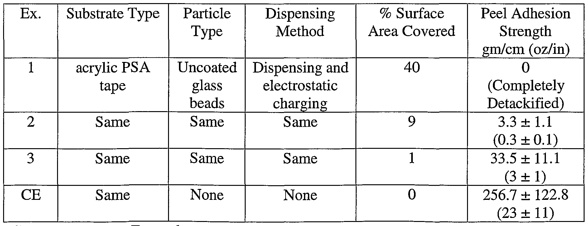
- a third example of a particle-embedded web involves controlling peel adhesion by adding nonadhesive particles. These webs are useful in making adhesives with controlled adhesion levels.
- the particles could also be hollow spheres with encapsulated material which becomes available during use.
- a film with microencapsulated fragrance can be used for perfume samples.
- a film with microencapsulated ink can be used as carbonless form paper.
- the particles can contain magnetic components that can be used as part of a radio frequency identification system to provide information about the item to which they are attached in an efficient, cost-effective manner.
- the web material can be a silicone rubber that will thermally cure during or after embedding the web with particles.
- the resultant material could be useful as an electrically conductive or thermally conductive pad.
- the desired amount of surface area covered by particles will vary by application, and can range from less than 1 % up to a monolayer of particles covering the entire surface.
- the percent coverage provided by a monolayer of particles will depend upon the packing density of the particles, which is in turn related to their shape. For spherical particles, a monolayer of particles corresponds to a percent surface area coverage of approximately 78%. Applications falling within this range include retroreflective sheeting, detackified adhesive films, and z-axis conductive adhesives.
- Suitable web materials include those that can be made receptive to the particles while dispensing the particles onto the web. Receptive means that the particles will remain approximately in the positions they assume immediately after being dispensed, until they can be permanently embedded in the web.
- the web can be a single or multiple layer construction.
- the web can be a layer of film or other material on top of a carrier layer. When a carrier layer is used, it can be a liner, which can be release coated. Alternatively, a continuous belt could be used as the carrier layer.
- the web onto which the particles are dispensed need not be continuous, and could be non-woven.
- Web materials that are pressure-sensitive adhesives at room temperature can have the particles permanently embedded in the adhesive such as by running the web through a nip roller, with or without pre-heating the film. It is also possible to dispense the particles onto a web made of a liner coated with the reactive precursor of a pressure sensitive adhesive, and then to cure the precursor after the particles have been added.
- Thermoplastic web materials may require heating to make them receptive. If heating is used, it is desirable to keep the temperature of the web below the temperature at which the thermoplastic will flow off of the liner.
- Useful thermoplastic films include those designed for use as thermoplastic adhesives, also known as hot-melt adhesives.
- Suitable pressure sensitive adhesive materials can include acrylics, vinyl ethers, natural or synthetic rubber-based materials, poly(alpha-olefins), and silicones. Pressure sensitive adhesives, as defined in the "Glossary of Terms Used in the Pressure Sensitive Tape Industry” provided by the Pressure Sensitive Tape Council, August 1985, are well known. Exemplary pressure sensitive adhesive materials include the acrylic pressure sensitive adhesive tape available from 3M under the trade designation "Scotch ® MagicTM
- Thermoplastic materials may be amorphous or semi-crystalline. Suitable thermoplastic materials include acrylics, polycarbonates, polyimides, polyphenylene ether, polyphenylene sulfide, acrylonitrile-butadiene-styrene copolymer (ABS), polyesters, ethylene vinyl acetate (EVA), polyurethanes, polyamides, block copolymers such as styrene-ethylene/butylene-styrene and polyether-block-amides, polyolefins, and derivatives of these. "Derivative" refers to a base molecule with additional substituents that are not reactive toward a crosslinking or polymerization reaction. Blends of thermoplastic materials may also be used. Tackifiers may also be included in the thermoplastic resin. Exemplary thermoplastic materials in film form include those commercially available from 3M under the trade designations "3M Thermo-Bond Film
- Suitable tackifier resins include those available under the following trade designations:
- TMINOL 135" from Arakawa Chemical, Chicago, PL
- NIREZ 2040 from Arizona Chemical, Panama City, FL
- PICOFYN T Hercules Inc., Wilmington, DE.
- thermosetting web materials can also be used. Depending upon the thermosetting material, it is possible that particles could be embedded in a material with an advanced state of cure. However, particularly if the particles cannot be embedded in partially or fully cured material, any heating to make the web receptive must be at a low enough web temperature that the particles can be embedded before the cure advances too far.
- Suitable thermosetting materials are those that can be made into web form while maintaining latency. Latency means that curing can be substantially prevented until the desired processing can be completed. Achieving this latency might require dark and/or cold processing conditions.
- Suitable thermosetting materials include epoxides, urethanes, cyanate esters, bismaleimides, phenolics, including nitrile phenolics, and combinations of these. Exemplary thermosetting materials that are commercially available in film form include those available from 3M under the trade designation "3M Scotch- Weld Structural Adhesive Film" including those having the following "AF" designations: "AF 42,” "AF
- Hybrid materials also can be used as the web.
- a hybrid material is a combination of at least two components where the components are compatible in the melt phase (where the combination of the components is a liquid), the components form a interpenetrating polymer network or semi-interpenetrating polymer network, and at least one component becomes infusible (the component cannot be dissolved or melted) after curing by heating or other methods such as light.
- the first component can be a crosslinkable material and the second component can be (a) a thermoplastic material, or (b) monomers, oligomers, or polymers (and any required curative) which can form a thermoplastic material, or (c) a thermosetting material, i.e., monomers, oligomers, or prepolymers (and any required curative) which can form a thermosetting material.
- the second component is chosen so that it is not reactive with the first component. It may be desirable, however, to add a third component which may be reactive with either or both of the crosslinkable material and second component to, for example, increase the cohesive strength of the bonded hybrid material.
- Suitable first components include thermosetting materials, such as those described above, as well as crosslinkable elastomers such as acrylics and urethanes.
- Suitable thermoplastic second components include those described above. Suitable thermoplastics, which can be formed in situ, i.e., with monomers, oligomers, or polymers (and any required curative) which can form a thermoplastic material without undergoing any significant crosslinking reaction would be readily apparent.
- Exemplary hybrid materials incorporating a second component (a) are described, for example, in WO 00/20526, U.S. Patent No. 5,709,948, and U.S. Patent No. 6,057,382.
- Exemplary hybrid materials incorporating a second component (b) are described, for example, in U.S. Patent No.
- Example 1 of U.S. Patent No. 5,086,088 illustrates an example of a thermoplastic material formed in situ.
- Suitable thermosetting second components include those described above.
- Exemplary hybrid materials incorporating a second component (c) are described, for example, in U.S. Patent No. 5,494,981.
- the web material may also include additives, such as film-forming materials, intended to improve the film handling properties of the final particle-embedded web.
- additives include thixotropic agents such as fumed silica; core- shell tougheners; pigments such as ferric oxide, brick dust, carbon black, and titanium oxide; fillers such as silica, magnesium sulfate, calcium sulfate, and beryllium aluminum silicate; clays such as betonite; glass beads; bubbles made from glass or phenolic resin; expandable microspheres, for example, microspheres commercially available from Expancel I-nc./Akzo Nobel, Duluth, GA, under the trade designation "Expancel DU"; antioxidants; UV-stabilizers; corrosion inhibitors, for example, those commercially available from W.R.
- thixotropic agents such as fumed silica
- core- shell tougheners such as ferric oxide, brick dust, carbon black, and titanium oxide
- fillers such as silica
- additives include those that provide thermal or electrical conductivity such as electrically or thermally conductive particles, electrically or thermally conductive woven or non- woven webs, or electrically or thermally conductive fibers. It may also be desirable to provide additives that function as energy absorbers for such curing methods as microwave curing.
- the invention uses a technique of dispensing and embedding the particles to provide a random, non-aggregating distribution.
- the particles are applied at a preselected density with a relatively uniform (number of particles per unit area) distribution of particles. This is accomplished without requiring any complicated screens or masks (although they can be used if desired for certain applications).
- An electrostatic charge can be applied to aid in the repulsion and mutual exclusion of the particles as they randomly land on the adhesive film. Also, the web can be buffed to further aid in the particle distribution.
- a web 12 such as an adhesive-coated thermoplastic film
- a supply roll 14 travels along a relatively horizontal path, although non-horizontal orientations can be used.
- the web can be supplied direct from a processing line or in any other known form. Any kind of web unwind device can be used.
- the web 12 can optionally pass through a pair of nip rollers (not shown), or through or over one or more driven or guide rollers 16. Next, the web 12 passes over a heated surface 18 to soften the web.
- a temperature sensing device such as a thermocouple, non-contact infrared sensor, or other similar device, monitors the temperature.
- the temperature of the heated surface 18 can be used as an indication of the web temperature but more preferably the temperature of the web 12 itself is measured.
- the heated surface 18 can be governed by a controller 20.
- the web 12 may contact the heated surface 18, thus being heated by contact, or it can pass above the heated surface, thus being heated by convection. If the web 12 passes above the heated surface 18, static charges created by sliding contact are minimized but more energy is required to heat the web.
- the heated surface is an electrical heating plate.
- the web 12 next passes by an optional static bar 22 to reduce static charge buildup on the web.
- an optional static bar 22 to reduce static charge buildup on the web.
- ionizing air and other known static elimination devices can be used. Static can already be present on the web from the unwinding of the web or the original coating process.
- the web 12 passes the particle dispenser 24 which dispenses particles 26 onto the surface of the web.
- an optional voltage source 28 is connected to the particle dispenser 24 to charge the particles 26 before they are dispensed onto the web.
- the voltage source 28 supplies a voltage sufficiently high to charge the particles 26.
- the web passes over a second heated surface 30, which is governed by a controller 32.
- a single controller can operate both heated surfaces 18, 30.
- a single heated surface can be used.
- the each heated surface 18, 30 is an electrical heating plate.
- other heating devices can be used.
- the web can pass over a cylindrical roll commonly known as a "hot can," the web can pass through an oven, or the web can pass over an infrared or induction heater. Heaters can be adjacent the top surface of the web as well as adjacent the bottom surface.
- the heated surface 18 is used to soften the web 12, or the coating on the web if the web is coated, making the surface tacky. This makes the web 12 receptive to the particles 26 which do not move on the web but are not yet securely fixed to the web.
- the heated surface 30, shown longer than the heated surface 18, is used to further heat the web 12 to drive the particles 26 into the coating. If multiple heated surfaces are used the relative lengths of the heated surfaces 18, 30 can be varied to accomplish their respective heating tasks.
- the heated surface 30 can heat the web 12 as the particles 26 are dispensed. Either at the heated surface 30 or after it, another optional static bar 34, or other static elimination device, can be used.
- the static bar 34 like the static bar 22, can be located over or under the web 12.
- the web 12 travels through a pair of nip rollers 36 which can optionally be driven.
- the pressure in the nip further drives the particles 26 into the web 12.
- One or two nip rollers can be used to embed the particles 26 into the web 12.
- a single roller can be used over a flat plate. Any kind of roller, including silicone rubber, rubber-coated, metal, and combinations or these, can be used as long as they do not crush the particles 26 in the web 12.
- the nip rollers 36 can also be heated to further drive the particles 26 into the web 12. Also, by heating the nip rollers 36, the heated surface 30 can be shortened and even eliminated.
- the web 12 passes around a drive roller 38 (if the nip rollers 36 are not driven) and to a windup roller 40 at a windup station, such as with an air- clutched winder.
- a windup roller 40 at a windup station, such as with an air- clutched winder.
- the web 12 can optionally pass over a stainless steel pacer roll.
- the voltage source 28 can apply a voltage to the dispenser 24 and either an opposite charge or ground can be applied to any combination of the heated surface 18 (grounding is shown), the static bar 34
- Another way to promote dispersion is to buff the surface of the web 12 after the particles are dispensed on it.
- a random orbital sander 42 (Finishing Sander Model 505, available from Porter Cable Company, Jackson TN) fitted with a soft painting pad (available under the trade designation EZ Paintr from EZ Paintr, Weston, Canada and described in U.S. Patent No. 3,369,268) can be used to spread the powder uniformly over the adhesive.
- This buffer 42 is also shown in Figure 1.
- the inventors have found that as the desired coverage area of the particles increases, buffing becomes a more desirable method of dispersing the particles in the film.
- An electrically charged plate 44 can be placed near the dispenser 24 to contain the dispensed powder.
- the plate 44 may be directly connected to the high voltage power supply 28, or connected to a separate power supply (not shown).
- a plate 46 which is electrically grounded may be used below the web at the particles dispenser 24.
- the plate 46 can be electrically heated.
- the particle dispenser 24 can include knurled rollers, gravity-fed reservoirs, and vibratory feeders.
- the system 10 can operate with any of variously known dispensers.
- the particle dispenser 24 shown in detail in Figures 2-4 is a novel cradle-type dispenser.
- the particles 26 to be dispensed are first held in the hopper 50, which can be covered by a lid 54.
- the hopper 50 can have an angled bottom to promote particle 26 flow to the front of the hopper.
- An opening on the front face at the bottom of the hopper 50 is covered with a screen 56. The screen openings should be large enough to let the largest particles 26 pass through while being dispensed but small enough to hold the particles back when the dispenser 24 is not operating.
- the particles 26 have a mean size of 43 ⁇ m and the screen 56 has 80 ⁇ m openings but the openings can be 65 to 105 ⁇ m (1.5 to 2.5 times the mean particle diameter) or 75 to 86 ⁇ m (1.75 to 2 times the mean particle diameter).
- the screen 56 should have consistent opening size and spacing to ensure even dispensing of particles 26 across the web 12.
- the screen can be a polyester or metal screen of the type typically used in the screen printing industry.
- the screen is a monofilament polyester, PW -180 x 55 screen manufactured by Saati America's Majestic Division, Somers NY.
- the cradle 52 includes a dispensing brush 58, adjustable cradle mounts 60, pivot points 62, a geared drive motor 64, counterweights 66, end plates 68, a support bar 70, a cleaning wire 72, and drive bearings 74.
- the dispensing brush 58 can be cylindrical with ends that permit it to be mounted in the drive bearings 74 and coupled to the drive motor 64.
- the surface of the brush 58 is covered with very fine, regularly spaced bristles of sufficiently small diameter to extend through the openings in the screen 56.
- the bristles can be made of polyamide resin or coated with graphite to improve conductivity.
- the bristles on the brush 58 in this embodiment are nylon, 26 ⁇ m in diameter and have a mean length of 0.368 cm (0.145 in). They are arranged in rows of 30.5 tufts/cm (12 tufts/in) with approximately 70 bristles per tuft and 56 rows/cm (22 rows/in) manufactured onto a 0.038 cm (0.015 in) polyester fabric backing by Collins & Aikmen Company, New York, NY. If the bristles are not spaced evenly or are laid out with irregular patterns, these patterns will be transferred to the web as the particles are dispensed. Thus, the brush 58 should have a flat surface and be true so that it contacts the screen evenly across the entire length of the dispenser 24 throughout it rotation.
- the brush 58 does not contact the screen evenly, the dispense rate of the particles across the web will vary.
- the brush can have other configurations.
- alternatives to the brush can be used, as described below.
- the brush 58 is mounted with sealed drive bearings 74 (bushings can be used) to ensure true rotation.
- the geared d.c. drive motor 64 (or any equivalent device, which can rotate the brush) rotates the brush 58 and controls the rotational speed of the brush by varying the voltage applied to the motor. This determines the dispense rate of the particles. Any other method and device for varying the rotation of the brush can be used.
- the drive bearings 74, drive motor 64, counterweights 66, and pivot points 62 are mounted to and held together by the end plates 68.
- the pivot points 62 are sealed bearings to ensure low friction swinging of the cradle 52.
- the entire cradle assembly can pivot freely on the pivot points 62 from the up position ( Figure 3) downwardly until the brush 58 touches the screen 56 ( Figure 4).
- the cradle 52 is supported at the pivot points 62 by the adjustable cradle mounts 60.
- the end plates 68 are structurally bound together by a support bar 70 which makes the ends of the cradle 52 move together to maintain alignment of the brush 58 with the screen 56. I-n this embodiment, the brush 58 must be precisely aligned with the screen 56 using the adjustable cradle mounts 60.
- the end plates are not mounted to adjustable cradle supports but to the support bar which is also able to pivot around its center allowing the brush to move freely and self-align with the screen.
- the cradle assembly can be pivoted manually or using any known system.
- the cradle mounts 60 are adjusted so that the distance, Dl, from the screen 56 to the central longitudinal axis of the brush 58 equals the radius of the brush. This ensures that when the cradle 52 is free hanging (without the counterweights 66) the brush surface touches the screen and does not significantly influence the force exerted against the screen.
- the counterweights 66 which are mounted off-axis at the front of the cradle 52, determine the force with which the brush 58 pushes against the screen 56. This force maintains intimate contact between the brush and screen during rotation and influences the dispense rate.
- the counterweights 66 can be moved further or closer to the pivot axis between the pivot points 62 on threaded rods to adjust the brush pressure.
- the dispenser used a pressure of 0.661 kg/linear meter (0.037 lb/linear inch) and had a range of 0.536 to 0.929 kg/linear meter (0.030 to 0.052 lb/linear inch), although other pressures can be used.
- the distance, D2 between the pivot axis and the central longitudinal axis of the brush should be equal to the vertical distance from the pivot axis to the center height of the screen to ensure that the brush 58 contacts the screen and not the metal hopper face above or below the screen.
- a cleaner can remove excess particles from the brush.
- the cleaner is a cleaning wire 72, tensioned between the end plates 68 on the front side of the brush 58 so that the wire just contacts the tips of the bristles. As the brush 58 turns and rubs against the cleaning wire 72, any excess particles 26 on the brush are removed to prevent buildup of particles on the brush and possible aggregation of particles on the web 12.
- the dispenser 24 is suspended above the web 12 at a distance close enough to reduce the effects of air currents on the dispense pattern. This distance can be 3cm from the cleaning wire 72 to the web 12.
- the hopper 50 is filled with the particles 26 to be dispensed and the lid 54 keeps out contaminants.
- the voltage is applied to the hopper to charge the particles 26.
- the drive motor 64 rotates the brush 58 so that the bristles move down across the surface of the screen 56. As the bristles move over the surface of the screen, they protrude through the openings of the screen and draw particles through to the outside, dispensing them onto the web 12. Any particles 26 that remain on the surface of the brush are cleaned off by the cleaning wire 72.
- the particles that are cleaned off the brush by the cleaning wire fall on to the web forming a second dispense zone. Because the two dispense zones are independent, they tend to further even out particle dispersion.
- the dispense rate for a given particle size is affected by the screen opening size, the brush rotational speed, the brush-to-screen pressure, the screen tension, and the proper adjustment of the distance Dl.
- the dispense rate increases as the screen opening size increases, as the brush rotational speed increases, as the screen tension decreases, and as the brush-to-screen pressure increases. As the distance Dl increases, the dispense rate decreases.
- the uniformity of coating weight across the web and dispersion of particles on the web are affected by brush-to-screen alignment, brush cleanliness, brush surface regularity and voltage in the following ways.
- the brush can be replaced by a knurled roller, such as used in printing industry.
- the screen is placed horizontally at the bottom of a hopper 50 and a brush is placed in contact with the screen. The powder in the hopper 50 dispenses as the brush rotates in contact with the screen by dragging the particles through the screen.
- Another screen can be placed horizontally at the bottom of the device to contact the brush as well.
- the second screen is below the brush and can assist in reducing aggregation if particles by breaking the clumps as they are forced through the bottom screen.
- a vibratory dispenser can be used to dispense powder.
- the dispense rate can be moderated.
- the path of the powder in the dispenser is modified by attaching a "hook" material (such as can be found in known hook and loop fasteners) in the path of the powder flow. This slows the dispense rate due to the restriction posed by the hooks to the flow of powder.
- the dispense rate can be moderated by using various grades of the hook material.
- Various microstructured surfaces could be used in the place of the hook material to modify the flow of particles. A linear relationship between the operating a.c. voltage of the vibratory dispenser and the powder dispense rate was established for a given flow medium.
- FIG. 5 is a micrograph showing silver coated glass beads embedded onto a thermoplastic adhesive. The sample area is 420 ⁇ m x 570 ⁇ m. An ancillary benefit to this more uniform particle distribution is that it provides a uniform appearance in the finished product. An advantage of using the inventive method to make z-axis conductive adhesive films is that it allows the use of large conductive particles.
- the size of the particles can be very similar to the thickness of the adhesive film, and because the particles span the thickness of the adhesive, the amount of material flow to make a bond is minimal, especially when compared to known thermoplastic-film based systems in which the particles are small compared to the thickness of the adhesive. This allows quick bonding of the conductive surface. This also ensures that the thickness of the final bond is uniform over a large part. This can help maintain the quality of a final product.
- the embedded-particle film product can be based on thermoplastic adhesive.
- the tack of the adhesive can be reactivated by heating. This can be done as many times as needed. Freedom to reactivate the adhesive is useful in applications where the bonded parts have to be reworked, removed, repaired, or repositioned.
- Model 3M90 (available from ASS Instrumentors, Incorporated, Strongville, OH) was used to measure the 180° angle peel adhesion strength as follows. First, the glass plate test surface of the peel tester was cleaned using methyl ethyl ketone and KIMWI-PES EX-L tissues (available from Kimberly-Clark Corporation, Roswell, GA). Next, a sample having a width of 1.9 cm (0.75 in) and a length of 25.4 cm (10.0 in) was placed lengthwise on the glass plate. The sample was secured to the glass substrate by passing a 2.27 kg (5 lb) rubber roller back and forth over the sample three times. Next, the sensor arm was extended lengthwise over the sample and the end furthest from the arm holder was attached to the sample. The opposite end of the sensor arm was then positioned in the arm holder and the tester was activated. The sample was peeled from the glass substrate at an angle of 180° and a rate of 229 cm/min (90 in/min).
- the first 2 seconds of data were not included in the analysis, to accommodate the startup of the test.
- the data taken between 2 and 5 seconds was analyzed for the average peel force, converted to a peel adhesion strength value, and normalized to a width of 2.5 cm (1 in).
- Four samples were measured and the results used to calculate the reported overall average peel adhesion strength (in gm/cm (oz/in)) and standard deviation.
- the surface area covered by embedded particles was evaluated using a microscope.
- Articles having embedded particles on their surface were examined at 20 X magnification using an OLYMPUS BX60 F5 (available from Olympus Optical Company, Ltd., Japan) microscope equipped with a video camera.
- a picture was taken at 366 X magnification of a randomly selected area and the image stored in a digital format for later manipulation.
- Six images, each having an area of 0.24 mm 2 were analyzed using SIGMASCAN PRO 5 image processing software (available from SPSS, Incorporated, Chicago, EL) to obtain a particle count in each of six randomly selected areas and an average particle count was calculated.
- the percentage of surface area covered was determined by multiplying the average cross-sectional area of a particle (obtained from the average particle size provided by the manufacturer) by the average total particle count in an imaged area, and dividing this number by the total area of the image. This number is multiplied by 100 to obtain the percentage.
- Articles having electrically conductive particles were evaluated for electrical resistance both through the thickness of the article (z axis) and across its surface (x-y plane, also referred to as "sheet resistance"). More specifically, for z axis resistivity, a film sample, having a width of about 15.2 cm (6 in) and a length of about 25.4 cm (10 in), was placed between two circular brass plates 0.318 cm (0.125 in) thick and having a diameter of 2.5 cm (1 in). The electrodes of a FLUKE 83 III Multimeter (available from FLUKE Corporation, Everett, WA) were attached to the brass plates which were then pressed together using finger pressure. The z axis resistance was recorded in ohms.
- the x-y plane (sheet) resistance of a sample having the dimensions above was measured using a PROSTAT Surface Resistance & Resistivity Indicator, Model PSI-870 (PROSTAT Corporatipn, Bensenville, J-L) by following the procedure described in the operations manual.
- the x-y plane resistance was recorded in ohms/square (also written as ohms/ ). Retroreflectivity
- Retroreflectivity of the coated samples were measured using a Field Retroreflectometer Model 920 available from Advanced Retro Technology Inc., Spring Valley, CA. The retroreflectivity is expressed in candles per lux per square meter (cd/lx/m 2 ). First, the instrument was calibrated using a standard sample provided by the manufacturer
- Scotch ® MagicTM Tape 810 an acrylic pressure sensitive adhesive tape measuring 1.9 cm (0.75 in) wide and 25.4 cm (10 in) long was embedded on the adhesive surface with uncoated Conduct-O-FilTM S-3000-S3P glass beads (an intermediate in the production of metal coated glass beads), available from Potters Industries, having an average particle diameter of 43 ⁇ m.
- the dispenser used was similar to that shown in
- Figures 2-4 and various surface area coverages were used. The following parameters were used: a web speed of 6.1 m/min (20 ft/min), electrically grounded heating plate temperature of about 20-25°C, a distance of 30 mm between the charging wire on the brush and the heating plate, an operating voltage of 0.4 V for rotating the brush, and a negative d.c. potential of 7 kV applied to the dispensing apparatus.
- the screen was kept taut by stretching it manually over the dispenser opening until there was no appreciable slack when pressed with a finger.
- the resulting particle embedded article was evaluated for surface area coverage and peel adhesion strength as described in the "Test Methods" above. The results are reported in Table 1 below.
- Example 1 was repeated with a web speed of 9.1 m/min (30 ft/min).
- the resulting particle embedded article was evaluated for surface area coverage and peel adhesion strength as described in the "Test Methods" above. The results are reported in Table 1 below.
- Example 1 was repeated with a web speed of 12.2 m/min (40 ft/min).
- the resulting particle embedded article was evaluated for surface area coverage and peel adhesion strength as described in the "Test Methods" above. The results are reported in Table 1 below.
- thermoplastic film was embedded with conductive silver-coated glass beads, S-3000-S3P (available from Potters Industries) having an average particle diameter of 43 ⁇ m by passing the thermoplastic film on the release liner through the dispensing apparatus similar to that described in Example 1.
- the following parameters were used: a web speed of 6.1 m/min (20 ft/min), a heating plate temperature of 85° C (maintained using a Temperature Controller Model 89810-02, available from Cole-Parmer Instrument Company, Vernon Hills, IL), a distance of 30 mm between the charging wire on the brush and the heating plate, and an operating voltage of 0.4 V for rotating the brush.
- the screen was kept taut by stretching it manually over the dispenser opening until there was no appreciable slack when pressed with a finger.
- the coated web was sent through the nip of two silicone rubber rolls.
- the resulting particle embedded article was evaluated for surface area coverage and resistivity as described in the "Test Methods" above. The results are reported in Table 2 below.
- Example 4 was repeated with a negative d.c. potential of 7 kV applied to the dispensing apparatus, and with the heating plate grounded.
- the resulting particle embedded article was evaluated for surface area coverage and resistivity as described in the "Test Methods" above. The results are reported in Table 2 below.
- Example 5 was repeated with the particle-embedded thermoplastic film buffed on the particle-containing surface using a finishing sander (Model 505, available from Porter
- a rubber adhesive-based tape was embedded with reflective particles and evaluated for retroreflectivity.
- Retroreflectivity is a special case of reflectivity; it describes reflection of incident light back at an angle of 180°.
- 3MTM Colored Paper Tape 256 (a printable flatback paper tape) was embedded on the adhesive surface with glass beads hemispherically coated with aluminum (available as Component B of 3MTM Reflective Ink 8010) using the apparatus and parameters described in Example 1 with the following modification.
- the operating voltage for rotating the brush was 1.5 V.
- the resulting particle embedded article was evaluated for surface area coverage and retroreflectivity as described in the "Test Methods" above. The results are reported in
- Example 7 was repeated with an operating voltage for rotating the brush of 3.0 V.
- the resulting particle embedded article was evaluated for surface area coverage and retroreflectivity as described in the "Test Methods" above. The results are reported in Table 3 below.
- Example 9
- Example 7 was repeated with an operating voltage for rotating the brush of 6.0 V.
- the resulting particle embedded article was evaluated for surface area coverage and retroreflectivity as described in the "Test Methods" above. The results are reported in Table 3 below.
- Example 9 was repeated with 3MTM Structural Bonding Tape 9245 (a heat curable, epoxy/acrylic hybrid pressure sensitive adhesive tape) used in place of 3MTM Colored Paper Tape 256.
- the resulting particle embedded article was evaluated for surface area coverage and retroreflectivity as described in the "Test Methods" above. The results are reported in Table 3 below.
Abstract
Description


Claims
Priority Applications (7)
| Application Number | Priority Date | Filing Date | Title |
|---|---|---|---|
| AT00965017T ATE263632T1 (en) | 2000-05-09 | 2000-09-14 | METHOD AND DEVICE FOR PRODUCING MATERIAL WEBS WITH EMBEDDED PARTICLES |
| DE60009756T DE60009756T2 (en) | 2000-05-09 | 2000-09-14 | METHOD AND DEVICE FOR PRODUCING MATERIAL CARRIAGES WITH EMBEDDED PARTICLES |
| EP00965017A EP1280612B1 (en) | 2000-05-09 | 2000-09-14 | Method and apparatus for making particle-embedded webs |
| KR1020027014953A KR100712586B1 (en) | 2000-05-09 | 2000-09-14 | Method and apparatus for making particle-embedded webs |
| JP2001582004A JP2004508918A (en) | 2000-05-09 | 2000-09-14 | Method and apparatus for producing a particle-embedded web |
| AU2000275812A AU2000275812A1 (en) | 2000-05-09 | 2000-09-14 | Method and apparatus for making particle-embedded webs |
| HK03104883.9A HK1054345B (en) | 2000-05-09 | 2003-07-08 | Method and apparatus for making particle-embedded webs |
Applications Claiming Priority (2)
| Application Number | Priority Date | Filing Date | Title |
|---|---|---|---|
| US09/567,316 US6569494B1 (en) | 2000-05-09 | 2000-05-09 | Method and apparatus for making particle-embedded webs |
| US09/567,316 | 2000-05-09 |
Publications (1)
| Publication Number | Publication Date |
|---|---|
| WO2001085358A1 true WO2001085358A1 (en) | 2001-11-15 |
Family
ID=24266666
Family Applications (1)
| Application Number | Title | Priority Date | Filing Date |
|---|---|---|---|
| PCT/US2000/025233 WO2001085358A1 (en) | 2000-05-09 | 2000-09-14 | Method and apparatus for making particle-embedded webs |
Country Status (10)
| Country | Link |
|---|---|
| US (2) | US6569494B1 (en) |
| EP (1) | EP1280612B1 (en) |
| JP (1) | JP2004508918A (en) |
| KR (1) | KR100712586B1 (en) |
| AT (1) | ATE263632T1 (en) |
| AU (1) | AU2000275812A1 (en) |
| DE (1) | DE60009756T2 (en) |
| HK (1) | HK1054345B (en) |
| MY (1) | MY125007A (en) |
| WO (1) | WO2001085358A1 (en) |
Cited By (7)
| Publication number | Priority date | Publication date | Assignee | Title |
|---|---|---|---|---|
| WO2003041877A1 (en) * | 2001-11-09 | 2003-05-22 | 3M Innovative Properties Company | Method and apparatus for making particle-embedded webs |
| WO2003047762A1 (en) * | 2001-12-05 | 2003-06-12 | Pergo (Europe) Ab | Strewing apparatus |
| US7034403B2 (en) | 2003-04-10 | 2006-04-25 | 3M Innovative Properties Company | Durable electronic assembly with conductive adhesive |
| US7695804B2 (en) | 2003-04-10 | 2010-04-13 | 3M Innovative Properties Company | Heat-activatable adhesive |
| CN107666967A (en) * | 2015-05-27 | 2018-02-06 | 兰达实验室(2012)有限公司 | Coating equipment |
| IT201700067511A1 (en) * | 2017-06-16 | 2018-12-16 | Valli Zabban S P A | METHOD FOR THE PRODUCTION OF A PHOTOLUMINESCENT PRODUCT AND PRODUCT OBTAINED, IN PARTICULAR A WATERPROOFING MEMBRANE OR AN ADHESIVE TAPE |
| WO2022118178A1 (en) * | 2020-12-04 | 2022-06-09 | 3M Innovative Properties Company | Method of transferring particles to a coating surface |
Families Citing this family (48)
| Publication number | Priority date | Publication date | Assignee | Title |
|---|---|---|---|---|
| US6569494B1 (en) * | 2000-05-09 | 2003-05-27 | 3M Innovative Properties Company | Method and apparatus for making particle-embedded webs |
| US6660326B2 (en) * | 2000-08-04 | 2003-12-09 | Tomoegawa Paper Co. Ltd. | Production method for monolayer powder film and production apparatus therefor |
| US8173857B1 (en) | 2000-12-20 | 2012-05-08 | Patrick Yananton | Adhesion of particles of active ingredients to an open pore substrate |
| US7654227B1 (en) | 2001-12-20 | 2010-02-02 | Pat Yananton | Absorbent pad for entrapping small and large particles, retaining liquids and eliminating odors |
| US7647890B1 (en) | 2001-12-20 | 2010-01-19 | Pat Yananton | Disposable non-woven pad and method for entrapping pet hair and dander |
| US7726260B1 (en) | 2000-12-20 | 2010-06-01 | Pat Yananton | Absorbent pad for entrapping small and coarse particles, retaining liquids and eliminating odors |
| US20050031823A1 (en) * | 2001-02-15 | 2005-02-10 | Integral Technologies, Inc. | Low cost conductive labels manufactured from conductive loaded resin-based materials |
| DE10118349A1 (en) * | 2001-04-12 | 2002-10-17 | Creavis Tech & Innovation Gmbh | Self-cleaning surfaces through hydrophobic structures and processes for their production |
| US20030017272A1 (en) * | 2001-07-20 | 2003-01-23 | Stevenson Michael J. | Bonding of granular materials to polyolefin surfaces |
| US6986933B2 (en) * | 2001-08-08 | 2006-01-17 | Tomoegawa Paper Co., Ltd. | Powdery single-layer film laminate and process for production the same |
| US6875278B2 (en) * | 2001-09-07 | 2005-04-05 | Material Sciences Corporation | Modular powder application system |
| WO2003029018A1 (en) * | 2001-10-01 | 2003-04-10 | Paradigma S.R.L. | Transfer of image with sublimating inks and medium in sheet form for performing it |
| US7297170B2 (en) * | 2002-07-26 | 2007-11-20 | 3M Innovative Properties Company | Method of using abrasive product |
| US6833014B2 (en) * | 2002-07-26 | 2004-12-21 | 3M Innovative Properties Company | Abrasive product, method of making and using the same, and apparatus for making the same |
| US7044989B2 (en) * | 2002-07-26 | 2006-05-16 | 3M Innovative Properties Company | Abrasive product, method of making and using the same, and apparatus for making the same |
| US20050211099A1 (en) * | 2004-03-23 | 2005-09-29 | Doughty David T | Spiral composite adsorbent material |
| JP2005276931A (en) * | 2004-03-23 | 2005-10-06 | Toshiba Corp | Semiconductor device and its manufacturing method |
| US20050228837A1 (en) * | 2004-04-08 | 2005-10-13 | Paul Marostica | Approximate number calculator |
| US7260999B2 (en) * | 2004-12-23 | 2007-08-28 | 3M Innovative Properties Company | Force sensing membrane |
| US7468199B2 (en) * | 2004-12-23 | 2008-12-23 | 3M Innovative Properties Company | Adhesive membrane for force switches and sensors |
| BRPI0609015A2 (en) * | 2005-03-11 | 2016-11-29 | 3M Innovative Properties Co | fastener to engage with a woven fabric, method for forming a fastener and disposable diaper. |
| US8802214B2 (en) | 2005-06-13 | 2014-08-12 | Trillion Science, Inc. | Non-random array anisotropic conductive film (ACF) and manufacturing processes |
| US20060280912A1 (en) * | 2005-06-13 | 2006-12-14 | Rong-Chang Liang | Non-random array anisotropic conductive film (ACF) and manufacturing processes |
| US7509881B2 (en) * | 2005-07-29 | 2009-03-31 | 3M Innovative Properties Company | Interdigital force switches and sensors |
| US20070085235A1 (en) * | 2005-10-18 | 2007-04-19 | Boyle Timothy J | Method and apparatus for continuously preparing crosslinked, solution-cast polymer film |
| US20070085234A1 (en) * | 2005-10-19 | 2007-04-19 | Boyle Timothy J | Method and apparatus for solution casting film with secondary component |
| US7636988B2 (en) * | 2006-09-11 | 2009-12-29 | 3M Innovative Properties Company | Methods for making fasteners |
| US7923488B2 (en) * | 2006-10-16 | 2011-04-12 | Trillion Science, Inc. | Epoxy compositions |
| US20080178436A1 (en) * | 2007-01-25 | 2008-07-31 | 3M Innovative Properties Company | Fastener webs with microstructured particles and methods of making same |
| WO2008130955A1 (en) * | 2007-04-17 | 2008-10-30 | National Starch And Chemical Investment Holding Corporation | Corrosion-resistant anisotropic conductive compositions |
| US20090087263A1 (en) * | 2007-09-28 | 2009-04-02 | Abe Martinez | Reflective Material Dispenser |
| US8276542B1 (en) | 2008-06-20 | 2012-10-02 | Patrick Yananton | Method and structure for entrapping soils carried by pet's paws, using a bonded, porous, web forming, highloft nonwoven pad or runner |
| US20110104989A1 (en) * | 2009-04-30 | 2011-05-05 | First Principles LLC | Dressing bar for embedding abrasive particles into substrates |
| CN103313800B (en) | 2011-02-16 | 2015-02-18 | 3M创新有限公司 | Electrostatic abrasive particle coating apparatus and method |
| JP5691777B2 (en) * | 2011-04-14 | 2015-04-01 | 株式会社Ihi | Powder rolling apparatus and powder rolling method |
| US9102851B2 (en) | 2011-09-15 | 2015-08-11 | Trillion Science, Inc. | Microcavity carrier belt and method of manufacture |
| US9475963B2 (en) | 2011-09-15 | 2016-10-25 | Trillion Science, Inc. | Fixed array ACFs with multi-tier partially embedded particle morphology and their manufacturing processes |
| US11011737B2 (en) * | 2012-05-16 | 2021-05-18 | Eskra Technical Products, Inc. | System and method of fabricating an electrochemical device |
| KR101350952B1 (en) * | 2012-09-17 | 2014-01-16 | 한국생산기술연구원 | Flux coating device |
| WO2016189511A1 (en) | 2015-05-27 | 2016-12-01 | Landa Labs (2012) Ltd. | Imaging device |
| JP6762323B2 (en) | 2015-05-27 | 2020-09-30 | ランダ ラブズ (2012) リミテッド | Printing methods and equipment for coating selected areas of a substrate with a film |
| US11701684B2 (en) | 2015-05-27 | 2023-07-18 | Landa Labs (2012) Ltd. | Method for coating a surface with a transferable layer of thermoplastic particles and related apparatus |
| CN107666986B (en) | 2015-06-02 | 2020-07-14 | 3M创新有限公司 | Method for transferring particles to a substrate |
| US10639827B2 (en) | 2015-12-22 | 2020-05-05 | 3M Innovative Properties Company | Eyelet for biomedical electrode and process for production thereof |
| US11304640B2 (en) | 2015-12-22 | 2022-04-19 | 3M Innovative Properties Company | Sensor for electrode and processes for production |
| EP3393746B1 (en) | 2015-12-22 | 2020-08-26 | 3M Innovative Properties Company | One-piece sensor for a bioelectrode and processes for production |
| EP3548292B1 (en) | 2016-11-30 | 2024-02-21 | Landa Labs (2012) Ltd. | Improvements in thermal transfer printing |
| CN110076057B (en) * | 2019-05-21 | 2020-09-25 | 浙江富欣达健康科技有限公司 | Automatic plastic spraying system for traffic guardrail production |
Citations (19)
| Publication number | Priority date | Publication date | Assignee | Title |
|---|---|---|---|---|
| GB809332A (en) * | 1954-07-02 | 1959-02-25 | Elmendorf Armin | Improvements in ligno-cellulosic fibre-board |
| FR2099256A5 (en) * | 1970-06-20 | 1972-03-10 | Herberts & Co K | Coated sheet material - by applying a powder - onto the sheet material from a fluted roller and heating |
| WO1986000829A1 (en) * | 1984-08-01 | 1986-02-13 | Ralf Larsson | A device for distribution of finely divided material over a surface |
| US4737112A (en) | 1986-09-05 | 1988-04-12 | American Telephone And Telegraph Company, At&T Bell Laboratories | Anisotropically conductive composite medium |
| US5086088A (en) | 1989-03-09 | 1992-02-04 | Minnesota Mining And Manufacturing Company | Epoxy-acrylate blend pressure-sensitive thermosetting adhesives |
| US5087494A (en) | 1991-04-12 | 1992-02-11 | Minnesota Mining And Manufacturing Company | Electrically conductive adhesive tape |
| US5221417A (en) | 1992-02-20 | 1993-06-22 | At&T Bell Laboratories | Conductive adhesive film techniques |
| US5240761A (en) | 1988-08-29 | 1993-08-31 | Minnesota Mining And Manufacturing Company | Electrically conductive adhesive tape |
| US5300340A (en) | 1988-02-26 | 1994-04-05 | Minnesota Mining And Manufacturing Company | Electrically conductive pressure-sensitive adhesive tape |
| EP0691660A1 (en) | 1994-05-10 | 1996-01-10 | Hitachi Chemical Co., Ltd. | Anisotropically electroconductive resin film |
| US5494981A (en) | 1995-03-03 | 1996-02-27 | Minnesota Mining And Manufacturing Company | Epoxy-cyanate ester compositions that form interpenetrating networks via a Bronsted acid |
| US5616206A (en) | 1993-06-15 | 1997-04-01 | Ricoh Company, Ltd. | Method for arranging conductive particles on electrodes of substrate |
| EP0818246A2 (en) * | 1996-07-10 | 1998-01-14 | Material Sciences Corporation | Powder atomizer |
| US5709948A (en) | 1995-09-20 | 1998-01-20 | Minnesota Mining And Manufacturing Company | Semi-interpenetrating polymer networks of epoxy and polyolefin resins, methods therefor, and uses thereof |
| DE19710821A1 (en) * | 1997-03-15 | 1998-09-17 | Philipp Waldinger | Distribution unit for sprinkling e.g. seeds onto food |
| US5851644A (en) | 1995-08-01 | 1998-12-22 | Loctite (Ireland) Limited | Films and coatings having anisotropic conductive pathways therein |
| US5916641A (en) | 1996-08-01 | 1999-06-29 | Loctite (Ireland) Limited | Method of forming a monolayer of particles |
| WO2000020526A1 (en) | 1998-10-02 | 2000-04-13 | Minnesota Mining And Manufacturing Company | Sealant composition, article and method |
| US6057382A (en) | 1998-05-01 | 2000-05-02 | 3M Innovative Properties Company | Epoxy/thermoplastic photocurable adhesive composition |
Family Cites Families (26)
| Publication number | Priority date | Publication date | Assignee | Title |
|---|---|---|---|---|
| CA452052A (en) * | 1948-10-19 | Minnesota Mining And Manufacturing Company | Method of and apparatus for applying coating materials | |
| US2681637A (en) * | 1950-12-04 | 1954-06-22 | Masonite Corp | Coating apparatus for applying a resin in particulate form |
| US3268766A (en) * | 1964-02-04 | 1966-08-23 | Du Pont | Apparatus for removal of electric charges from dielectric film surfaces |
| US3457080A (en) | 1966-02-07 | 1969-07-22 | Lipoma Electronics Co | Method of and apparatus for the electrostatic application of solid particles to food products |
| DE1591054B2 (en) * | 1966-08-05 | 1976-12-16 | Communications Satellite Corp., Washington, D.C | MESSAGE RECEIVER FOR FREQUENCY MODULATED SIGNALS |
| US3470417A (en) * | 1966-10-03 | 1969-09-30 | Eastman Kodak Co | Method of altering electrostatic charge on an insulating material |
| US3369268A (en) | 1967-06-02 | 1968-02-20 | Painter Corp E Z | Paint applying tool |
| DE1790220C3 (en) * | 1968-09-30 | 1978-12-07 | Hoechst Ag, 6000 Frankfurt | Method and device for the electrostatic coating of surfaces with electrically conductive, semi-conductive or non-conductive material |
| GB1330393A (en) | 1970-06-23 | 1973-09-19 | Sun Oil Co | Stabilized oil extended rubber compositions |
| US4170193A (en) * | 1976-04-16 | 1979-10-09 | Ball Corporation | Apparatus for applying lubricating materials to metallic substrates |
| EP0157003B1 (en) * | 1984-02-10 | 1988-11-23 | Präzisions-Werkzeuge AG | Method of measuring the quantity of particle coating on a metallic body to be coated with said particle coating, device for carrying out the method, and its application |
| US4655161A (en) * | 1985-12-13 | 1987-04-07 | Ralston Purina Company | Apparatus for depositing chocolate chips and the like onto edible food products |
| US4779558A (en) * | 1986-08-14 | 1988-10-25 | Pierce Companies, Inc. | Image permanence device |
| US5032422A (en) * | 1989-12-26 | 1991-07-16 | Ball Corporation | Electrostatically depositing and electrostatically neutralizing |
| SE468305B (en) * | 1991-04-24 | 1992-12-14 | Moelnlycke Ab | PROCEDURE AND DEVICE FOR APPLYING PARTICLES TO A CURRENT MATERIAL |
| US5324359A (en) * | 1992-02-25 | 1994-06-28 | Nouvas Manufacturing Technology Co. | Material deposition device |
| US5314090A (en) | 1992-03-23 | 1994-05-24 | Terronics Development Corporation | Material feeder |
| US5316197A (en) * | 1992-12-01 | 1994-05-31 | Cemen Tech, Inc. | Feeder for adding fibrous material to a conveyor having concrete ingredients |
| US5366140A (en) * | 1993-09-30 | 1994-11-22 | Minnesota Mining And Manufacturing Company | Patterned array of uniform metal microbeads |
| AUPM969294A0 (en) * | 1994-11-25 | 1994-12-22 | Technological Resources Pty Limited | Apparatus for sieving a particulate material |
| US5817374A (en) * | 1996-05-31 | 1998-10-06 | Electrox Corporation | Process for patterning powders into thick layers |
| DE19642178A1 (en) * | 1996-10-12 | 1998-04-16 | Beiersdorf Ag | Electrically conductive transfer tape |
| DE69722781T2 (en) * | 1996-12-27 | 2004-04-29 | Dai Nippon Printing Co., Ltd. | METHOD AND DEVICE FOR TRANSFER TO CURVED SURFACES |
| US6143374A (en) * | 1998-02-04 | 2000-11-07 | E. I. Du Pont De Nemours And Company | Method for precise placement of an array of single particles on a surface |
| US6197114B1 (en) * | 1998-11-05 | 2001-03-06 | Material Sciences Corporation | Power feeding apparatus having an adjustable feed width |
| US6569494B1 (en) * | 2000-05-09 | 2003-05-27 | 3M Innovative Properties Company | Method and apparatus for making particle-embedded webs |
-
2000
- 2000-05-09 US US09/567,316 patent/US6569494B1/en not_active Expired - Fee Related
- 2000-09-14 JP JP2001582004A patent/JP2004508918A/en active Pending
- 2000-09-14 AU AU2000275812A patent/AU2000275812A1/en not_active Abandoned
- 2000-09-14 EP EP00965017A patent/EP1280612B1/en not_active Expired - Lifetime
- 2000-09-14 KR KR1020027014953A patent/KR100712586B1/en not_active IP Right Cessation
- 2000-09-14 AT AT00965017T patent/ATE263632T1/en not_active IP Right Cessation
- 2000-09-14 DE DE60009756T patent/DE60009756T2/en not_active Expired - Lifetime
- 2000-09-14 WO PCT/US2000/025233 patent/WO2001085358A1/en active IP Right Grant
-
2001
- 2001-04-20 MY MYPI20011881A patent/MY125007A/en unknown
-
2003
- 2003-03-03 US US10/378,484 patent/US6834612B2/en not_active Expired - Fee Related
- 2003-07-08 HK HK03104883.9A patent/HK1054345B/en not_active IP Right Cessation
Patent Citations (19)
| Publication number | Priority date | Publication date | Assignee | Title |
|---|---|---|---|---|
| GB809332A (en) * | 1954-07-02 | 1959-02-25 | Elmendorf Armin | Improvements in ligno-cellulosic fibre-board |
| FR2099256A5 (en) * | 1970-06-20 | 1972-03-10 | Herberts & Co K | Coated sheet material - by applying a powder - onto the sheet material from a fluted roller and heating |
| WO1986000829A1 (en) * | 1984-08-01 | 1986-02-13 | Ralf Larsson | A device for distribution of finely divided material over a surface |
| US4737112A (en) | 1986-09-05 | 1988-04-12 | American Telephone And Telegraph Company, At&T Bell Laboratories | Anisotropically conductive composite medium |
| US5300340A (en) | 1988-02-26 | 1994-04-05 | Minnesota Mining And Manufacturing Company | Electrically conductive pressure-sensitive adhesive tape |
| US5240761A (en) | 1988-08-29 | 1993-08-31 | Minnesota Mining And Manufacturing Company | Electrically conductive adhesive tape |
| US5086088A (en) | 1989-03-09 | 1992-02-04 | Minnesota Mining And Manufacturing Company | Epoxy-acrylate blend pressure-sensitive thermosetting adhesives |
| US5087494A (en) | 1991-04-12 | 1992-02-11 | Minnesota Mining And Manufacturing Company | Electrically conductive adhesive tape |
| US5221417A (en) | 1992-02-20 | 1993-06-22 | At&T Bell Laboratories | Conductive adhesive film techniques |
| US5616206A (en) | 1993-06-15 | 1997-04-01 | Ricoh Company, Ltd. | Method for arranging conductive particles on electrodes of substrate |
| EP0691660A1 (en) | 1994-05-10 | 1996-01-10 | Hitachi Chemical Co., Ltd. | Anisotropically electroconductive resin film |
| US5494981A (en) | 1995-03-03 | 1996-02-27 | Minnesota Mining And Manufacturing Company | Epoxy-cyanate ester compositions that form interpenetrating networks via a Bronsted acid |
| US5851644A (en) | 1995-08-01 | 1998-12-22 | Loctite (Ireland) Limited | Films and coatings having anisotropic conductive pathways therein |
| US5709948A (en) | 1995-09-20 | 1998-01-20 | Minnesota Mining And Manufacturing Company | Semi-interpenetrating polymer networks of epoxy and polyolefin resins, methods therefor, and uses thereof |
| EP0818246A2 (en) * | 1996-07-10 | 1998-01-14 | Material Sciences Corporation | Powder atomizer |
| US5916641A (en) | 1996-08-01 | 1999-06-29 | Loctite (Ireland) Limited | Method of forming a monolayer of particles |
| DE19710821A1 (en) * | 1997-03-15 | 1998-09-17 | Philipp Waldinger | Distribution unit for sprinkling e.g. seeds onto food |
| US6057382A (en) | 1998-05-01 | 2000-05-02 | 3M Innovative Properties Company | Epoxy/thermoplastic photocurable adhesive composition |
| WO2000020526A1 (en) | 1998-10-02 | 2000-04-13 | Minnesota Mining And Manufacturing Company | Sealant composition, article and method |
Cited By (7)
| Publication number | Priority date | Publication date | Assignee | Title |
|---|---|---|---|---|
| WO2003041877A1 (en) * | 2001-11-09 | 2003-05-22 | 3M Innovative Properties Company | Method and apparatus for making particle-embedded webs |
| WO2003047762A1 (en) * | 2001-12-05 | 2003-06-12 | Pergo (Europe) Ab | Strewing apparatus |
| US7034403B2 (en) | 2003-04-10 | 2006-04-25 | 3M Innovative Properties Company | Durable electronic assembly with conductive adhesive |
| US7695804B2 (en) | 2003-04-10 | 2010-04-13 | 3M Innovative Properties Company | Heat-activatable adhesive |
| CN107666967A (en) * | 2015-05-27 | 2018-02-06 | 兰达实验室(2012)有限公司 | Coating equipment |
| IT201700067511A1 (en) * | 2017-06-16 | 2018-12-16 | Valli Zabban S P A | METHOD FOR THE PRODUCTION OF A PHOTOLUMINESCENT PRODUCT AND PRODUCT OBTAINED, IN PARTICULAR A WATERPROOFING MEMBRANE OR AN ADHESIVE TAPE |
| WO2022118178A1 (en) * | 2020-12-04 | 2022-06-09 | 3M Innovative Properties Company | Method of transferring particles to a coating surface |
Also Published As
| Publication number | Publication date |
|---|---|
| HK1054345B (en) | 2005-03-04 |
| DE60009756T2 (en) | 2005-04-28 |
| MY125007A (en) | 2006-07-31 |
| EP1280612B1 (en) | 2004-04-07 |
| JP2004508918A (en) | 2004-03-25 |
| US6834612B2 (en) | 2004-12-28 |
| KR20030022795A (en) | 2003-03-17 |
| US6569494B1 (en) | 2003-05-27 |
| AU2000275812A1 (en) | 2001-11-20 |
| HK1054345A1 (en) | 2003-11-28 |
| US20030129302A1 (en) | 2003-07-10 |
| KR100712586B1 (en) | 2007-05-16 |
| ATE263632T1 (en) | 2004-04-15 |
| EP1280612A1 (en) | 2003-02-05 |
| DE60009756D1 (en) | 2004-05-13 |
Similar Documents
| Publication | Publication Date | Title |
|---|---|---|
| EP1280612B1 (en) | Method and apparatus for making particle-embedded webs | |
| US20020119255A1 (en) | Method and apparatus for making particle-embedded webs | |
| KR100733682B1 (en) | Method and apparatus for manufacturing a powder single-layered film | |
| JP5160713B2 (en) | Coatings and methods | |
| JP3353150B2 (en) | Reservoir that can be impregnated with an active ingredient solution for iontophoretic devices for transdermal absorption administration of pharmaceuticals, and method for producing the reservoir | |
| CN1077761C (en) | Component carrier tape | |
| CA2368166A1 (en) | Abrasive article, method of making same, and abrading apparatus | |
| KR20170095871A (en) | Coated compressive subpad for chemical mechanical polishing | |
| KR20180086244A (en) | A process for depositing dry powder particles onto a substrate and for adhesively bonding particles to a substrate | |
| JP3812682B2 (en) | Method for producing anisotropic conductive resin film-like molded product | |
| JP3712923B2 (en) | Method for manufacturing powder layer laminate and apparatus for manufacturing the same | |
| JP3681162B2 (en) | Powder monolayer continuous production equipment | |
| JP2000025135A (en) | Functionally flocked fabric article and its manufacture | |
| JP3783785B2 (en) | Method for manufacturing anisotropic conductive resin film adhesive and method for connecting between fine circuits | |
| TW572832B (en) | Process for preparation of single powder film on long ruler-like film substrate and apparatus for preparing the same | |
| KR0119976B1 (en) | Device and method of preparing adhesive materials | |
| KR100405300B1 (en) | Positionable and reusable pressure sensitive adhesive sheet and method of preparing the same | |
| JPH03295111A (en) | Anisotropic conductor and manufacture thereof | |
| JP3392081B2 (en) | Powder single layer coating method | |
| HU222516B1 (en) | Method and device for making male-part of separable fastener, male-part and separable fastener comprising thereof | |
| JP2003024869A (en) | Method for producing colored particle | |
| JP2002273337A (en) | Method for manufacturing colored sphere | |
| JPH0323942A (en) | Preparation of sheet coated with beads having different particle sizes |
Legal Events
| Date | Code | Title | Description |
|---|---|---|---|
| AK | Designated states |
Kind code of ref document: A1 Designated state(s): AE AG AL AM AT AT AU AZ BA BB BG BR BY BZ CA CH CN CR CU CZ CZ DE DE DK DK DM DZ EE EE ES FI FI GB GD GE GH GM HR HU ID IL IN IS JP KE KG KP KR KR KZ LC LK LR LS LT LU LV MA MD MG MK MN MW MX MZ NO NZ PL PT RO RU SD SE SG SI SK SK SL TJ TM TR TT TZ UA UG UZ VN YU ZA ZW |
|
| AL | Designated countries for regional patents |
Kind code of ref document: A1 Designated state(s): GH GM KE LS MW MZ SD SL SZ TZ UG ZW AM AZ BY KG KZ MD RU TJ TM AT BE CH CY DE DK ES FI FR GB GR IE IT LU MC NL PT SE BF BJ CF CG CI CM GA GN GW ML MR NE SN TD TG |
|
| DFPE | Request for preliminary examination filed prior to expiration of 19th month from priority date (pct application filed before 20040101) | ||
| 121 | Ep: the epo has been informed by wipo that ep was designated in this application | ||
| WWE | Wipo information: entry into national phase |
Ref document number: 1020027014953 Country of ref document: KR |
|
| WWE | Wipo information: entry into national phase |
Ref document number: 2000965017 Country of ref document: EP |
|
| WWP | Wipo information: published in national office |
Ref document number: 2000965017 Country of ref document: EP |
|
| WWP | Wipo information: published in national office |
Ref document number: 1020027014953 Country of ref document: KR |
|
| WWG | Wipo information: grant in national office |
Ref document number: 2000965017 Country of ref document: EP |