WO2001071928A2 - High efficiency, high performance communications system employing multi-carrier modulation - Google Patents
High efficiency, high performance communications system employing multi-carrier modulation Download PDFInfo
- Publication number
- WO2001071928A2 WO2001071928A2 PCT/US2001/009179 US0109179W WO0171928A2 WO 2001071928 A2 WO2001071928 A2 WO 2001071928A2 US 0109179 W US0109179 W US 0109179W WO 0171928 A2 WO0171928 A2 WO 0171928A2
- Authority
- WO
- WIPO (PCT)
- Prior art keywords
- sub
- data
- stream
- channel
- channel data
- Prior art date
Links
Classifications
-
- H—ELECTRICITY
- H04—ELECTRIC COMMUNICATION TECHNIQUE
- H04B—TRANSMISSION
- H04B7/00—Radio transmission systems, i.e. using radiation field
- H04B7/14—Relay systems
- H04B7/15—Active relay systems
- H04B7/204—Multiple access
-
- H—ELECTRICITY
- H04—ELECTRIC COMMUNICATION TECHNIQUE
- H04B—TRANSMISSION
- H04B7/00—Radio transmission systems, i.e. using radiation field
- H04B7/02—Diversity systems; Multi-antenna system, i.e. transmission or reception using multiple antennas
- H04B7/04—Diversity systems; Multi-antenna system, i.e. transmission or reception using multiple antennas using two or more spaced independent antennas
- H04B7/0413—MIMO systems
- H04B7/0417—Feedback systems
-
- H—ELECTRICITY
- H04—ELECTRIC COMMUNICATION TECHNIQUE
- H04B—TRANSMISSION
- H04B7/00—Radio transmission systems, i.e. using radiation field
- H04B7/02—Diversity systems; Multi-antenna system, i.e. transmission or reception using multiple antennas
- H04B7/04—Diversity systems; Multi-antenna system, i.e. transmission or reception using multiple antennas using two or more spaced independent antennas
- H04B7/06—Diversity systems; Multi-antenna system, i.e. transmission or reception using multiple antennas using two or more spaced independent antennas at the transmitting station
- H04B7/0613—Diversity systems; Multi-antenna system, i.e. transmission or reception using multiple antennas using two or more spaced independent antennas at the transmitting station using simultaneous transmission
- H04B7/0615—Diversity systems; Multi-antenna system, i.e. transmission or reception using multiple antennas using two or more spaced independent antennas at the transmitting station using simultaneous transmission of weighted versions of same signal
- H04B7/0619—Diversity systems; Multi-antenna system, i.e. transmission or reception using multiple antennas using two or more spaced independent antennas at the transmitting station using simultaneous transmission of weighted versions of same signal using feedback from receiving side
- H04B7/0621—Feedback content
- H04B7/0626—Channel coefficients, e.g. channel state information [CSI]
-
- H—ELECTRICITY
- H04—ELECTRIC COMMUNICATION TECHNIQUE
- H04B—TRANSMISSION
- H04B7/00—Radio transmission systems, i.e. using radiation field
- H04B7/02—Diversity systems; Multi-antenna system, i.e. transmission or reception using multiple antennas
- H04B7/04—Diversity systems; Multi-antenna system, i.e. transmission or reception using multiple antennas using two or more spaced independent antennas
- H04B7/08—Diversity systems; Multi-antenna system, i.e. transmission or reception using multiple antennas using two or more spaced independent antennas at the receiving station
-
- H—ELECTRICITY
- H04—ELECTRIC COMMUNICATION TECHNIQUE
- H04B—TRANSMISSION
- H04B7/00—Radio transmission systems, i.e. using radiation field
- H04B7/02—Diversity systems; Multi-antenna system, i.e. transmission or reception using multiple antennas
- H04B7/12—Frequency diversity
-
- H—ELECTRICITY
- H04—ELECTRIC COMMUNICATION TECHNIQUE
- H04L—TRANSMISSION OF DIGITAL INFORMATION, e.g. TELEGRAPHIC COMMUNICATION
- H04L25/00—Baseband systems
- H04L25/02—Details ; arrangements for supplying electrical power along data transmission lines
- H04L25/0202—Channel estimation
- H04L25/0204—Channel estimation of multiple channels
-
- H—ELECTRICITY
- H04—ELECTRIC COMMUNICATION TECHNIQUE
- H04L—TRANSMISSION OF DIGITAL INFORMATION, e.g. TELEGRAPHIC COMMUNICATION
- H04L25/00—Baseband systems
- H04L25/02—Details ; arrangements for supplying electrical power along data transmission lines
- H04L25/0202—Channel estimation
- H04L25/024—Channel estimation channel estimation algorithms
- H04L25/0242—Channel estimation channel estimation algorithms using matrix methods
- H04L25/0248—Eigen-space methods
-
- H—ELECTRICITY
- H04—ELECTRIC COMMUNICATION TECHNIQUE
- H04L—TRANSMISSION OF DIGITAL INFORMATION, e.g. TELEGRAPHIC COMMUNICATION
- H04L27/00—Modulated-carrier systems
- H04L27/0008—Modulated-carrier systems arrangements for allowing a transmitter or receiver to use more than one type of modulation
-
- H—ELECTRICITY
- H04—ELECTRIC COMMUNICATION TECHNIQUE
- H04L—TRANSMISSION OF DIGITAL INFORMATION, e.g. TELEGRAPHIC COMMUNICATION
- H04L27/00—Modulated-carrier systems
- H04L27/18—Phase-modulated carrier systems, i.e. using phase-shift keying
- H04L27/20—Modulator circuits; Transmitter circuits
- H04L27/2032—Modulator circuits; Transmitter circuits for discrete phase modulation, e.g. in which the phase of the carrier is modulated in a nominally instantaneous manner
- H04L27/2053—Modulator circuits; Transmitter circuits for discrete phase modulation, e.g. in which the phase of the carrier is modulated in a nominally instantaneous manner using more than one carrier, e.g. carriers with different phases
-
- H—ELECTRICITY
- H04—ELECTRIC COMMUNICATION TECHNIQUE
- H04L—TRANSMISSION OF DIGITAL INFORMATION, e.g. TELEGRAPHIC COMMUNICATION
- H04L27/00—Modulated-carrier systems
- H04L27/32—Carrier systems characterised by combinations of two or more of the types covered by groups H04L27/02, H04L27/10, H04L27/18 or H04L27/26
- H04L27/34—Amplitude- and phase-modulated carrier systems, e.g. quadrature-amplitude modulated carrier systems
-
- H—ELECTRICITY
- H04—ELECTRIC COMMUNICATION TECHNIQUE
- H04L—TRANSMISSION OF DIGITAL INFORMATION, e.g. TELEGRAPHIC COMMUNICATION
- H04L5/00—Arrangements affording multiple use of the transmission path
- H04L5/003—Arrangements for allocating sub-channels of the transmission path
- H04L5/0048—Allocation of pilot signals, i.e. of signals known to the receiver
-
- H—ELECTRICITY
- H04—ELECTRIC COMMUNICATION TECHNIQUE
- H04L—TRANSMISSION OF DIGITAL INFORMATION, e.g. TELEGRAPHIC COMMUNICATION
- H04L25/00—Baseband systems
- H04L25/02—Details ; arrangements for supplying electrical power along data transmission lines
- H04L25/0202—Channel estimation
- H04L25/0224—Channel estimation using sounding signals
- H04L25/0226—Channel estimation using sounding signals sounding signals per se
-
- H—ELECTRICITY
- H04—ELECTRIC COMMUNICATION TECHNIQUE
- H04L—TRANSMISSION OF DIGITAL INFORMATION, e.g. TELEGRAPHIC COMMUNICATION
- H04L5/00—Arrangements affording multiple use of the transmission path
- H04L5/0001—Arrangements for dividing the transmission path
- H04L5/0014—Three-dimensional division
- H04L5/0023—Time-frequency-space
Definitions
- the present invention relates to data communication. More particularly, the present invention relates to a novel and improved communications system employing multi-carrier modulation and having high efficiency, improved performance, and enhanced flexibility.
- CDMA code division multiple access
- the CDMA system supports voice and data communication between users over a terrestrial link.
- the use of CDMA techniques in a multiple access communication system is disclosed in U.S. Patent No. 4,901,307, entitled “SPREAD SPECTRUM MULTIPLE ACCESS COMMUNICATION SYSTEM USING SATELLITE OR TERRESTRIAL REPEATERS,” and U.S. Patent No.
- An IS-95 compliant CDMA system is capable of supporting voice and data services over the forward and reverse communications links.
- each voice call or each traffic data transmission is assigned a- dedicated channel having a variable but limited data rate.
- the traffic or voice data is partitioned into code channel frames that are 20 msec in duration with data rates as high as 14.4 Kbps. The frames are then transmitted over the assigned channel.
- a method for transmitting traffic data in code channel frames of fixed size is described in U.S. Patent No. 5,504,773, entitled “METHOD AND APPARATUS FOR THE FORMATTING OF DATA FOR TRANSMISSION,” assigned to the assignee of the present invention and incorporated herein by reference.
- voice services impose stringent and fixed delay requirements whereas data services can usually tolerate variable amounts of delay.
- the overall one-way delay of speech frames is typically required to be less than 100 msec.
- the delay for data frames is typically a variable parameter that can be advantageously used to optimize the overall efficiency of the data communications system.
- data frames may employ more efficient error correcting coding techniques requiring longer delays that cannot be tolerated by voice frames.
- voice frames may be limited to the use of less efficient coding techniques having shorter delays.
- GOS grade of service
- the GOS of a data communications system is typically defined as the total delay incurred in the transfer of a particular amount of data.
- Soft handoff results in redundant transmissions from two or more base stations to improve reliability.
- this additional reliability may not be required for data transmission because data frames received in error may be retransmitted.
- the transmit power needed to support soft handoff may be more efficiently used for transmitting additional data.
- the IS-95 CDMA system is designed to efficiently transmit voice data, and is also capable of transmitting traffic data.
- the design of the channel structure and the data frame format pursuant to IS-95 have been optimized for voice data.
- a communications system based on IS- 95 that is enhanced for data services is disclosed in U.S. Patent Application Serial No. 08/963,386, entitled “METHOD AND APPARATUS FOR HIGH RATE PACKET DATA TRANSMISSION,” filed November 3, 1997, assigned to the assignee of the present invention and incorporated herein by reference.
- the present invention is directed to a novel and improved communications system capable of providing increased spectral efficiency, improved performance, and enhanced flexibility by employing a combination of antenna, frequency, and temporal diversity.
- the communications system can be operative to concurrently support a number of transmissions of various types (e.g., control, broadcast, voice, traffic data, and so on) that may have disparate requirements.
- various types e.g., control, broadcast, voice, traffic data, and so on
- An embodiment of the invention provides a transmitter unit for use in a communications system and configurable to provide antenna, frequency, or temporal diversity, or a combination thereof, for transmitted signals.
- the transmitter unit includes a system data processor, one or more modulators, and one or more antennas.
- the system data processor receives and partitions an input data stream into a number of (K) channel data streams and further processes the channel data streams to generate one or more (N ⁇ ) modulation symbol vector streams.
- Each modulation symbol vector stream includes a sequence of modulation symbol vectors representative of data in one or more channel data streams.
- Each modulator modulates a respective modulation symbol vector stream to provide a modulated signal, and each antenna receives and transmits a respective modulated signal.
- Each modulator typically includes an inverse (fast) Fourier transform (IFFT) and a cyclic prefix generator.
- IFFT inverse (fast) Fourier transform
- the IFFT generates time-domain representations of the modulation symbol vectors, and the cyclic prefix generator repeats a portion of the time-domain representation of each modulation symbol vector.
- the system data processor may include one or more channel data processors, encoders, demultiplexers, and combiners.
- each encoder encodes a respective channel data stream to generate an encoded data stream
- each channel data processor processes a respective encoded data stream to generate a stream of modulation symbols
- each demultiplexer demultiplexes the stream of modulation symbols into one or more symbol sub-streams
- each combiner selectively combines the symbol sub-streams to generate a modulation symbol vector stream for an associated antenna.
- the channel data streams are modulated using multi-carrier modulation (e.g., orthogonal frequency division multiplexing (OFDM) modulation).
- the multi-carrier modulation partitions the system operating bandwidth, W, into a number of (L) sub-bands. Each sub-band is associated with a different center frequency and corresponds to one sub-channel.
- the modulation symbol vectors are generated and transmitted in a manner to provide antenna, frequency, or temporal diversity, or a combination thereof.
- the data for a particular channel data stream may be transmitted from one or more antennas, on one or more sub- bands of the system operating bandwidth, and at one or more time periods to respectively provide antenna, frequency, and temporal diversity.
- Various communications modes e.g., diversity and MIMO may be supported and are described in greater detail below.
- Each channel data stream, each sub-channel, each antenna, or some other unit of transmission can be modulated with a particular modulation scheme selected from a set that includes, for example, M-PSK and M-QAM.
- the encoding can be achieved on each channel data stream, each sub- channel, and so on.
- Pre-conditioning of the data may also be performed at the transmitter unit using channel state information (CSI) descriptive of the characteristics of the communications links.
- CSI channel state information
- Such CSI may include, for example, the eigenmodes corresponding to, or the C/I values for, the communications links, which are described below.
- Time division multiplexing TDM may also be used to increase flexibility, especially for traffic data transmission.
- the channel data streams may thus be transmitted in time slots, with each time slot having a duration that is related to, for example, the length of a modulation symbol.
- a voice call may be assigned a portion of the available system resources (e.g., a particular sub-channel) to minimize processing delay. Traffic data for a particular transmission may be aggregated and transmitted in one or more time slots for improved efficiency. Pilot and other types of data may also be multiplexed and transmitted on selected time slots.
- a receiver unit that includes, for example, at least one antenna, at least one front end processor, at least one (fast) Fourier transform (FFT), a processor, at least one demodulator, and at least one decoder.
- Each antenna receives one or more modulated signals and provides the received signal to a respective front end processor that processes the signal to generate samples.
- Each FFT converts the samples from a respective front end processor into transformed representations.
- the transformed representations from the at least one FFT processor are then processed by the processor into one or more symbol streams, with each symbol stream corresponding to a particular transmission (e.g., control, broadcast, voice, or traffic data) being processed.
- Each demodulator demodulates a respective symbol stream to generate demodulated data, and each decoder decodes respective demodulated data to generate decoded data.
- the modulated signals are generated and transmitted and/or received in a manner to provide antenna, frequency, or temporal diversity, or a combination thereof, as described below.
- Yet another embodiment of the invention provides a method for generating and transmitting one or more modulated signals.
- an input data stream is received and partitioned into a number of channel data streams.
- the channel data streams are then encoded with one or more encoding schemes and modulated with one or more modulation schemes to generate modulation symbols.
- Symbols corresponding to the sub-channels of each antenna are then combined into modulation symbol vectors, which are then provided as a modulation symbol vector stream.
- the modulation symbol vectors are generated and transmitted in a manner to provide antenna, frequency, or temporal diversity, or a combination thereof.
- FIG. 1 is a diagram of a multiple-input multiple-output (MIMO) communications system
- FIG. 2 is a diagram that graphically illustrates a specific example of a transmission from a transmit antenna at a transmitter unit
- FIG. 3 is a block diagram of an embodiment of a data processor and a modulator of the communications system shown in FIG. 1;
- FIGS. 4A and 4B are block diagrams of two embodiments of a channel data processor that can be used for processing one channel data steam such as control, broadcast, voice, or traffic data;
- FIGS. 5A through 5C are block diagrams of an embodiment of the processing units that can be used to generate the transmit signal shown in FIG. 2;
- FIG. 6 is a block diagram of an embodiment of a receiver unit, having multiple receive antennas, which can be used to receive one or more channel data streams; and
- FIG. 7 shows plots that illustrate the spectral efficiency achievable with some of the operating modes of a communications system in accordance with one embodiment.
- FIG. 1 is a diagram of a multiple-input multiple-output (MIMO) communications system 100 capable of implementing some embodiments of the invention.
- Communications system 100 can be operative to provide a combination of antenna, frequency, and temporal diversity to increase spectral efficiency, improve performance, and enhance flexibility.
- Increased spectral efficiency is characterized by the ability to transmit more bits per second per Hertz (bps/Hz) when and where possible to better utilize the available system bandwidth. Techniques to obtain higher spectral efficiency are described in further detail below.
- Improved performance may be quantified, for example, by a lower bit-error-rate (BER) or frame-error-rate
- FER link carrier-to-noise-plus-interference ratio
- C/I link carrier-to-noise-plus-interference ratio
- communications system 100 includes a first system 110 in communication with a second system 120.
- System 110 includes a (transmit) data processor 112 that (1) receives or generates data, (2) processes the data to provide antenna, frequency, or temporal diversity, or a combination thereof, and (3) provides processed modulation symbols to a number of modulators (MOD) 114a through 114t. Each modulator 114 further processes the modulation symbols and generates an RF modulated signal suitable for transmission.
- the RF modulated signals from modulators 114a through 114t are then transmitted from respective antennas 116a through 116t over communications links 118 to system 120.
- system 120 includes a number of receive antennas 122a through 122r that receive the transmitted signals and provide the received signals to respective demodulators (DEMOD) 124a through 124r.
- each receive antenna 122 may receive signals from one or more transmit antennas 116 depending on a number of factors such as, for example, the operating mode used at system 110, the directivity of the transmit and receive antennas, the characteristics of the communications links, and others.
- Each demodulator 124 demodulates the respective received signal using a demodulation scheme that is complementary to the modulation scheme used at the transmitter.
- the demodulated symbols from demodulators 124a through 124r are then provided to a (receive) data processor 126 that further processes the symbols to provide the output data.
- the data processing at the transmitter and receiver units is described in further detail below.
- FIG. 1 shows only the forward link transmission from system 110 to system 120. This configuration may be used for data broadcast and other one-way data transmission applications.
- a reverse link from system 120 to system 110 is also provided, although not shown in FIG. 1 for simplicity.
- each of systems 110 and 120 may operate as a transmitter unit or a receiver unit, or both concurrently, depending on whether data is being transmitted from, or received at, the unit.
- communications system 100 is shown to include one transmitter unit (i.e., system 110) and one receiver unit (i.e., system 120).
- system 110 transmitter unit
- receiver unit i.e., system 120
- a single transmitter unit may be used to concurrently transmit data to a number of receiver units.
- a receiver unit may concurrently receive transmissions from a number of transmitter units.
- the communications system of the invention may include any number of transmitter and receiver units.
- Each transmitter unit may include a single transmit antenna or a number of transmit antennas, such as that shown in FIG. 1.
- each receiver unit may include a single receive antenna or a number of receive antennas, again such as that shown in FIG. 1.
- the communications system may include a central system (i.e., similar to a base station in the IS-95 CDMA system) having a number of antennas that transmit data to, and receive data from, a number of remote systems (i.e., subscriber units, similar to remote stations in the CDMA system), some of which may include one antenna and others of which may include multiple antennas.
- a central system i.e., similar to a base station in the IS-95 CDMA system
- remote systems i.e., subscriber units, similar to remote stations in the CDMA system
- antenna diversity increases and performance improves, as described below.
- an antenna refers to a collection of one or more antenna elements that are distributed in space.
- the antenna elements may be physically located at a single site or distributed over multiple sites.
- Antenna elements physically co-located at a single site may be operated as an antenna array (e.g., such as for a CDMA base station).
- An antenna network consists of a collection of antenna arrays or elements that are physically separated (e.g., several CDMA base stations).
- An antenna array or an antenna network may be designed with the ability to form beams and to transmit multiple beams from the antenna array or network.
- a CDMA base station may be designed with the capability to transmit up to three beams to three different sections of a coverage area (or sectors) from the same antenna array. Thus, the three beams may be viewed as three transmissions from three antennas.
- the communications system of the invention can be designed to provide a multi-user, multiple access communications scheme capable of supporting subscriber units having different requirements as well as capabilities.
- the scheme allows the system's total operating bandwidth, W, (e.g., 1.2288 MHz) to be efficiently shared among different types of services that may have highly disparate data rate, delay, and quality of service (QOS) requirements.
- Examples of such disparate types of services include voice services and data services.
- Voice services are typically characterized by a low data rate (e.g., 8 kbps to 32 kbps), short processing delay (e.g., 3 msec to 100 msec overall one-way delay), and sustained use of a communications channel for an extended period of time.
- voice services typically require a small fraction of the system resources to be dedicated to each voice call for the duration of the call.
- data services are characterized by "bursty" traffics in which variable amounts of data are sent at sporadic times. The amount of data can vary significantly from burst-to-burst and from user-to-user.
- the communications system of the invention can be designed with the capability to allocate a portion of the available resources to voice services as required and the remaining resources to data services.
- a fraction of the available system resources may also be dedicated for certain data services or certain types of data services.
- the distribution of data rates achievable by each subscriber unit can vary widely between some minimum and maximum instantaneous values (e.g., from 200 kbps to over 20 Mbps).
- the achievable data rate for a particular subscriber unit at any given moment may be influenced by a number of factors such as the amount of available transmit power, the quality of the communications link (i.e., the C/I), the coding scheme, and others.
- the data rate requirement of each subscriber unit may also vary widely between a minimum value (e.g., 8 kbps, for a voice call) all the way up to the maximum supported instantaneous peak rate (e.g., 20 Mbps for bursty data services).
- the percentage of voice and data traffic is typically a random variable that changes over time.
- the communications system of the invention is designed with the capability to dynamic allocate the available resources based on the amount of voice and data traffic.
- a scheme to dynamically allocate resources is described below.
- Another scheme to allocate resources is described in the aforementioned U.S. Patent Application Serial No. 08/963,386.
- the communications system of the invention provides the above- described features and advantages, and is capable of supporting different types of services having disparate requirements. The features are achieved by employing antenna, frequency, or temporal diversity, or a combination thereof. In some embodiments of the invention, antenna, frequency, or temporal diversity can be independently achieved and dynamically selected.
- antenna diversity refers to the transmission and /or reception of data over more than one antenna
- frequency diversity refers to the transmission of data over more than one sub-band
- temporal diversity refers to the transmission of data over more than one time period.
- Antenna, frequency, and temporal diversity may include subcategories.
- transmit diversity refers to the use of more than one transmit antenna in a manner to improve the reliability of the communications link
- receive diversity refers to the use of more than one receive antenna in a manner to improve the reliability of the communications link
- spatial diversity refers to the use of multiple transmit and receive antennas to improve the reliability and/or increase the capacity of the communications link.
- Transmit and receive diversity can also be used in combination to improve the reliability of the communications link without increasing the link capacity.
- Various combinations of antenna, frequency, and temporal diversity can thus be achieved and are within the scope of the present invention.
- Frequency diversity can be provided by use of a multi-carrier modulation scheme such as orthogonal frequency division multiplexing (OFDM), which allows for transmission of data over various sub-bands of the operating bandwidth.
- OFDM orthogonal frequency division multiplexing
- Temporal diversity is achieved by transmitting the data over different times, which can be more easily accomplished with the use of time-division multiplexing (TDM).
- antenna diversity is achieved by employing a number of (N ⁇ ) transmit antennas at the transmitter unit or a number of (N R ) receive antennas at the receiver unit, or multiple antennas at both the transmitter and receiver units.
- N ⁇ transmit antennas
- N R receive antennas
- an RF modulated signal from a transmitter unit may reach the receiver unit via a number of transmission paths.
- the characteristics of the transmission paths typically vary over time based on a number of factors.
- antenna diversity is dynamically provided based on the characteristics of the communications link to provide the required performance. For example, higher degree of antenna diversity can be provided for some types of communication (e.g./ signaling), for some types of services (e.g., voice), for some communications link characteristics (e.g., low C/I), or for some other conditions or considerations.
- higher degree of antenna diversity can be provided for some types of communication (e.g./ signaling), for some types of services (e.g., voice), for some communications link characteristics (e.g., low C/I), or for some other conditions or considerations.
- antenna diversity includes transmit diversity and receive diversity.
- transmit diversity data is transmitted over multiple transmit antennas.
- additional processing is performed on the data transmitted from the transmit antennas to achieved the desired diversity.
- the data transmitted from different transmit antennas may be delayed or reordered in time, or coded and interleaved across the available transmit antennas.
- frequency and temporal diversity may be used in conjunction with the different transmit antennas.
- receive diversity modulated signals are received on multiple receive antennas, and diversity is achieved by simply receiving the signals via different transmission paths.
- frequency diversity can be achieved by employing a multi-carrier modulation scheme.
- OFDM orthogonal frequency division multiple access
- the overall transmission channel is essentially divided into a number of (L) parallel sub-channels that are used to transmit the same or different data.
- the overall transmission channel occupies the total operating bandwidth of W, and each of the sub-channels occupies a sub- band having a bandwidth of W/L and centered at a different center frequency.
- Each sub-channel has a bandwidth that is a portion of the total operating bandwidth.
- Each of the sub-channels may also be considered an independent data transmission channel that may be associated with a particular (and possibly unique) processing, coding, and modulation scheme, as described below.
- the data may be partitioned and transmitted over any defined set of two or more sub-bands to provide frequency diversity. For example, the transmission to a particular subscriber unit may occur over sub-channel 1 at time slot 1, sub-channel 5 at time slot 2, sub-channel 2 at time slot 3, and so on. As another example, data for a particular subscriber unit may be transmitted over sub-channels 1 and 2 at time slot 1 (e.g., with the same data being transmitted on both sub-channels), sub-channels 4 and 6 at time slot 2, only sub-channel 2 at time slot 3, and so on. Transmission of data over different sub-channels over time can improve the performance of a communications system experiencing frequency selective fading and channel distortion. Other benefits of OFDM modulation are described below.
- temporal diversity is achieved by transmitting data at different times, which can be more easily accomplished using time division multiplexing (TDM).
- TDM time division multiplexing
- data transmission occurs over time slots that may be selected to provide immunity to time dependent degradation in the communications link.
- Temporal diversity may also be achieved through the use of interleaving. For example, the transmission to a particular subscriber unit may occur over time slots 1 through x, or on a subset of the possible time slots from 1 through x (e.g., time slots 1, 5, 8, and so on).
- the amount of data transmitted at each time slot may be variable or fixed. Transmission over multiple time slots improves the likelihood of correct data reception due to, for example, impulse noise and interference.
- the combination of antenna, frequency, and temporal diversity allows the communications system of the invention to provide robust performance. Antenna, frequency, and/or temporal diversity improves the likelihood of correct reception of at least some of the transmitted data, which may then be used (e.g., through decoding) to correct for some errors that may have occurred in the other transmissions.
- the combination of antenna, frequency, and temporal diversity also allows the communications system to concurrently accommodate different types of services having disparate data rate, processing delay, and quality of service requirements.
- the communications system of the invention can be designed and operated in a number of different communications modes, with each communications mode employing antenna, frequency, or temporal diversity, or a combination thereof.
- the communications modes include, for example, a diversity communications mode and a MIMO communications mode.
- the diversity communications mode employs transmit and/or receive diversity, frequency, or temporal diversity, or a combination thereof, and is generally used to improve the reliability of the communications link.
- the transmitter unit selects a modulation and coding scheme (i.e., configuration) from a finite set of possible configurations, which are known to the receiver units. For example, each overhead and common channel may be associated with a particular configuration that is known to all receiver units.
- the mode and/or configuration may be known a priori (e.g., from a previous set up) or negotiated (e.g., via a common channel) by the receiver unit.
- the diversity communications mode data is transmitted on one or more sub-channels, from one or more antennas, and at one or more time periods.
- the allocated sub-channels may be associated with the same antenna, or may be sub-channels associated with different antennas.
- the diversity communications mode which is also referred to as a "pure" diversity communications mode
- data is transmitted from all available transmit antennas to the destination receiver unit.
- the pure diversity communications mode can be used in instances where the data rate requirements are low or when the C/I is low, or when both are true.
- the MIMO communications mode employs antenna diversity at both ends of the communication link and is generally used to improve both the reliability and increase the capacity of the communications link.
- the MIMO communications mode may further employ frequency and/or temporal diversity in combination with the antenna diversity.
- the MIMO communications mode which may also be referred to herein as the spatial communications mode, employs one or more processing modes to be described below.
- the diversity communications mode generally has lower spectral efficiency than the MIMO communications mode, especially at high C/I levels. However, at low to moderate C/I values, the diversity communications mode achieves comparable efficiency and can be simpler to implement. In general, the use of the MIMO communications mode provides greater spectral efficiency when used, particularly at moderate to high C/I values. The MIMO communications mode may thus be advantageously used when the data rate requirements are moderate to high.
- the communications system can be designed to concurrently support both diversity and MIMO communications modes.
- the communications modes can be applied in various manners and, for increased flexibility, may be applied independently on a sub-channel basis.
- the MIMO communications mode is typically applied to specific users.
- each communications mode may be applied on each sub-channel independently, across a subset of sub-channels, across all sub-channels, or on some other basis.
- the use of the MIMO communications mode may be applied to a specific user (e.g., a data user) and, concurrently, the use of the diversity communications mode may be applied to another specific user (e.g., a voice user) on a different sub-channel.
- the diversity communications mode may also be applied, for example, on sub-channels experiencing higher path loss.
- the communications system of the invention can also be designed to support a number of processing modes.
- additional processing can be performed at the transmitter unit to further improve performance and increase efficiency.
- Full channel state information (CSI) or partial CSI may be available to the transmitter unit.
- Full CSI includes sufficient characterization of the propagation path (i.e., amplitude and phase) between all pairs of transmit and receive antennas for each sub-band.
- Full CSI also includes the C/I per sub-band.
- the full CSI may be embodied in a set of matrices of complex gain values that are descriptive of the conditions of the transmission paths from the transmit antennas to the receive antennas, as described below.
- Partial CSI may include, for example, the C/I of the sub-band .
- the transmitter unit preconditions the signals presented to the transmit antennas in a way that is unique to a specific receiver unit (e.g., the preconditioning is performed for each sub-band assigned to that receiver unit).
- the intended receiver unit can demodulate the transmission.
- a full-CSI based MIMO communication can only be demodulated by the receiver unit associated with the CSI used to precondition the transmitted signals.
- the transmitter unit employs a common modulation and coding scheme (e.g., on each data channel transmission), which then can be (in theory) demodulated by all receiver units.
- a single receiver unit can specify it's C/I, and the modulation employed on all antennas can be selected accordingly (e.g., for reliable transmission) for that receiver unit.
- Other receiver units can attempt to demodulate the transmission and, if they have adequate C/I, may be able to successfully recover the transmission.
- a common (e.g., broadcast) channel can use a no-CSI processing mode to reach all users.
- the full-CSI processing is briefly described below.
- a simple approach is to decompose the multi-input multi-output channel into a set of independent channels.
- the left eigenvectors may be used to transmit different data streams.
- n is an N R -vector representing noise plus interference.
- the eigenvector decomposition of the Hermitian matrix formed by the product of the channel matrix with its conjugate-transpose can be expressed as:
- the transmitter converts a set of N ⁇ modulation symbols b using the eigenvector matrix E.
- the pre-conditioning can thus be achieved by a matrix multiply operation expressed as: '11' '12'
- b v b 2 , ... and b ⁇ are respectively the modulation symbols for a particular sub-channel at transmit antennas 1, 2, ... N ⁇ , where each modulation symbol can be generated using, for example, M-PSK, M-QAM, and so on, as described below;
- the eigenvector matrix is unitary. Thus, if the elements of b have equal power, the elements of x also have equal power.
- the receiver performs a channel-matched-filter operation, followed by multiplication by the right eigenvectors.
- the transmitter unit can thus select a modulation alphabet (i.e., signal constellation) for each of the eigenvectors based on the C/I that is given by the eigenvalue. Providing that the channel conditions do not change appreciably in the interval between the time the CSI is measured at the receiver and reported and used to precondition the transmission at the transmitter, the performance of the communications system will then be equivalent to that of a set of independent AWGN channels with known C/I's.
- a modulation alphabet i.e., signal constellation
- the MIMO communications mode is applied to a channel data stream that is transmitted on one particular subchannel from four transmit antennas.
- the channel data stream is demultiplexed into four data sub-streams, one data sub-stream for each transmit antenna.
- Each data sub-stream is then modulated using a particular modulation scheme (e.g., M-PSK, M-QAM, or other) selected based on the CSI for that sub-band and for that transmit antenna.
- M-PSK e.g., M-PSK, M-QAM, or other
- Four modulation sub-streams are thus generated for the four data sub-streams, with each modulation sub-streams including a stream of modulation symbols.
- the four modulation sub-streams are then pre-conditioned using the eigenvector matrix, as expressed above in equation (1), to generate pre- conditioned modulation symbols.
- the four streams of pre-conditioned modulation symbols are respectively provided to the four combiners of the four transmit antennas.
- Each combiner combines the received preconditioned modulation symbols with the modulation symbols for the other sub-channels to generate a modulation symbol vector stream for the associated transmit antenna.
- the full-CSI based processing is typically employed in the MIMO communications mode where parallel data streams are transmitted to a specific user on each of the channel eigenmodes for the each of the allocated sub-channels. Similar processing based on full CSI can be performed where transmission on only a subset of the available eigenmodes is accommodated in each of the allocated sub-channels(e.g., to implement beam steering). Because of the cost associated with the full-CSI processing (e.g., increased complexity at the transmitter and receiver units, increased overhead for the transmission of the CSI from the receiver unit to the transmitter unit, and so on), full-CSI processing can be applied in certain instances in the MIMO communications mode where the additional increase in performance and efficiency is justified.
- less descriptive information on the transmission path may be available and can be used to pre-condition the data prior to transmission.
- the C/I of each of the sub-channels may be available. The C/I information can then be used to control the transmission from various transmit antennas to provide the required performance in the sub-channels of interest and increase system capacity.
- full-CSI based processing modes denote processing modes that use full CSI
- partial-CSI based processing modes denote processing modes that use partial CSI.
- the full-CSI based processing modes include, for example, the full-CSI MIMO mode that utilizes full-CSI based processing in the MIMO communications mode.
- the partial-CSI based modes include, for example, the partial-CSI MIMO mode that utilizes partial-CSI based processing in the MIMO communications mode.
- full-CSI or partial-CSI processing is employed to allow the transmitter unit to pre-condition the data using the available channel state information (e.g., the eigenmodes or C/I)
- feedback information from the receiver unit is required, which uses a portion of the reverse link capacity.
- the cost should to be factored into the choice of which processing mode to employ.
- the partial-CSI based processing mode requires less overhead and may be more efficient in some instances.
- the no-CSI based processing mode requires no overhead and may also be more efficient than the full-CSI based processing mode or the partial-CSI based processing mode under some other circumstances.
- the transmitter unit has CSI and uses the eigenmodes representative of the characteristics of the communications links to transmit independent channel data streams, then the sub-channels allocated in this case are typically uniquely assigned to a single user.
- the modulation and coding scheme employed is common for all users (i.e. th CSI employed at the transmitter is not user-specific), then it is possible that information transmitted in this processing mode could be received and decoded by more than one user, depending on their C/I.
- FIG. 2 is a diagram that graphically illustrates at least some of the aspects of the communications system of the invention.
- FIG. 2 shows a specific example of a transmission from one of N ⁇ transmit antennas at a transmitter unit.
- the horizontal axis is time and the vertical axis is frequency.
- the transmission channel includes 16 sub- channels and is used to transmit a sequence of OFDM symbols, with each OFDM symbol covering all 16 sub-channels (one OFDM symbol is indicated at the top of FIG. 2 and includes all 16 sub-bands).
- a TDM structure is also illustrated in which the data transmission is partitioned into time slots, with each time slot having the duration of, for example, the length of one modulation symbol (i.e., each modulation symbol is used as the TDM interval).
- the available sub-channels can be used to transmit signaling, voice, traffic data, and others.
- the modulation symbol at time slot 1 corresponds to pilot data, which is periodically transmitted to assist the receiver units synchronize and perform channel estimation.
- pilot data which is periodically transmitted to assist the receiver units synchronize and perform channel estimation.
- Other techniques for distributing pilot data over time and frequency can also be used and are within the scope of the present invention.
- it may be advantageous to utilize a particular modulation scheme during the pilot interval if all sub-channels are employed e.g., a PN code with a chip duration of approximately 1/W). Transmission of the pilot modulation symbol typically occurs at a particular frame rate, which is usually selected to be fast enough to permit accurate tracking of variations in the communications link.
- the time slots not used for pilot transmissions can then be used to transmit various types of data.
- sub-channels 1 and 2 may be reserved for the transmission of control and broadcast data to the receiver units.
- the data on these sub-channels is generally intended to be received by all receiver units.
- some of the messages on the control channel may be user specific, and can be encoded accordingly.
- Voice data and traffic data can be transmitted in the remaining subchannels.
- sub-channel 3 at time slots 2 through 9 is used for voice call 1
- sub-channel 4 at time slots 2 through 9 is used for voice call 2
- sub-channel 5 at time slots 5 through 9 is used for voice call 3
- sub-channel 6 at time slots 7 through 9 is used for voice call 5.
- the remaining available sub-channels and time slots may be used for transmissions of traffic data.
- data 1 transmission uses sub-channels 5 through 16 at time slot 2 and sub-channels 7 through 16 at time slot 7
- data 2 transmission uses sub-channels 5 through 16 at time slots 3 and 4 and sub-channels 6 through 16 at time slots 5
- data 3 transmission uses sub-channels 6 through 16 at time slot 6
- data 4 transmission uses sub-channels 7 through 16 at time slot 8
- data 5 transmission uses sub-channels 7 through 11 at time slot 9
- data 6 transmission uses sub-channels 12 through 16 at time slot 9.
- Data 1 through 6 transmissions can represent transmissions of traffic data to one or more receiver units.
- the communications system of the invention flexibly supports the transmissions of traffic data.
- a particular data transmission e.g., data 2
- multiple data transmissions e.g., data 5 and 6
- a data transmission e.g., data 1
- voice data may be multiplexed with traffic data and transmitted on a single subchannel.
- the multiplexing of the data transmissions can potentially change from OFDM symbol to symbol.
- the communications mode may be different from user to user (e.g., from one voice or data transmission to other).
- the voice users may use the diversity communications mode
- the data users may use the MIMO communications modes.
- Antenna, frequency, and temporal diversity may be respectively achieved by transmitting data from multiple antennas, on multiple subchannels in different sub-bands, and over multiple time slots.
- antenna diversity for a particular transmission e.g., voice call 1
- Frequency diversity for a particular transmission e.g., voice call 1
- a combination of antenna and frequency diversity may be obtained by transmitting data from two or more antennas and on two or more sub-channels.
- Temporal diversity may be achieved by transmitting data over multiple time slots. For example, as shown in FIG. 2, data 1 transmission at time slot 7 is a portion (e.g., new or repeated) of the data 1 transmission at time slot 2.
- the same or different data may be transmitted from multiple antennas and /or on multiple sub-bands to obtain the desired diversity.
- the data may be transmitted on: (1) one sub-channel from one antenna, (2) one sub-channel (e.g., sub-channel 1) from multiple antennas, (3) one sub-channel from all N ⁇ antennas, (4) a set of sub-channels (e.g., subchannels 1 and 2) from one antenna, (5), a set of sub-channels from multiple antennas, (6) a set of sub-channels from all N ⁇ antennas, or (7) a set of channels from a set of antennas (e.g., sub-channel 1 from antennas 1 and 2 at one time slot, sub-channels 1 and 2 from antenna 2 at another time slot, and so on).
- any combination of sub-channels and antennas may be used to provide antenna and frequency diversity.
- each sub-channel at each time slot for each transmit antenna may be viewed as an independent unit of transmission (i.e., a modulation symbol) that can be used to transmit any type of data such as pilot, signaling, broadcast, voice, traffic data, and others, or a combination thereof (e.g., multiplexed voice and traffic data).
- a voice call may be dynamically assigned different sub-channels over time.
- each modulation symbol may be generated from a modulation scheme (e.g., M-PSK, M-QAM, and others) that results in the best use of the resource at that particular time, frequency, and space.
- a modulation scheme e.g., M-PSK, M-QAM, and others
- a voice call may be assigned to a particular sub-channel for the duration of the call, or until such time as a sub-channel reassignment is performed.
- signaling and/or broadcast data may be designated to some fixed subchannels (e.g., sub-channel 1 for control data and sub-channel 2 for broadcast data, as shown FIG. 2) so that the receiver units know a priori which subchannels to demodulate to receive the data.
- each data transmission channel or sub-channel may be restricted to a particular modulation scheme (e.g., M-PSK, M-QAM) for the duration of the transmission or until such time as a new modulation scheme is assigned. For example, in FIG.
- voice call 1 on sub-channel 3 may use QPSK
- voice call 2 on sub-channel 4 may use 16-QAM
- data 1 transmission at time slot 2 may use 8-PSK
- data 2 transmission at time slots 3 through 5 may use 16-QAM, and so on.
- TDM allows for greater flexibility in the transmission of voice data and traffic data, and various assignments of resources can be contemplated. For example, a user can be assigned one sub-channel for each time slot or, equivalently, four sub-channels every fourth time slot, or some other allocations. TDM allows for data to be aggregated and transmitted at designated time slot(s) for improved efficiency. If voice activity is implemented at the transmitter, then in the intervals where no voice is being transmitted, the transmitter may assign other users to the sub-channel so that the sub-channel efficiency is maximized.
- the transmitter can decrease (or turn-off) the power transmitted in the sub-channel, reducing the interference levels presented to other users in the system that are using the same sub-channel in another cell in the network.
- the same feature can be also extended to the overhead, control, data, and other channels.
- FIG. 3 is a block diagram of an embodiment of data processor 112 and modulator 114 of system 110 in FIG. 1.
- the aggregate input data stream that includes all data to be transmitted by system 110 is provided to a demultiplexer (DEMUX) 310 within data processor 112.
- Demultiplexer 310 demultiplexes the input data stream into a number of (K) channel data stream, S_ through S k .
- K channel data stream
- Each channel data stream may correspond to, for example, a signaling channel, a broadcast channel, a voice call, or a traffic data transmission.
- Each channel data stream is provided to a respective encoder 312 that encodes the data using a particular encoding scheme.
- the encoding may include error correction coding or error detection coding, or both, used to increase the reliability of the link. More specifically, such encoding may include, for example, interleaving, convolutional coding, Turbo coding, Trellis coding, block coding (e.g., Reed-Solomon coding), cyclic redundancy check (CRC) coding, and others. Turbo encoding is described in further detail in U.S. Patent Application Serial No.
- the encoding can be performed on a per channel basis, i.e., on each channel data stream, as shown in FIG. 3.
- the encoding may also be performed on the aggregate input data stream, on a number of channel data streams, on a portion of a channel data stream, across a set of antennas, across a set of sub-channels, across a set of sub-channels and antennas, across each sub-channel, on each modulation symbol, or on some other unit of time, space, and frequency.
- the encoded data from encoders 312a through 312k is then provided to a data processor 320 that processes the data to generate modulation symbols.
- data processor 320 assigns each channel data stream to one or more sub-channels, at one or more time slots, and on one or more antennas.
- data processor 320 may assign one sub-channel on one antenna (if transmit diversity is not used) or multiple antennas (if transmit diversity is used) for as many time slots as needed for that call. For a channel data stream corresponding to a signaling or broadcast channel, data processor 320 may assign the designated sub-channel(s) on one or more antennas, again depending on whether transmit diversity is used. Data processor 320 then assigns the remaining available resources for channel data streams corresponding to data transmissions. Because of the burstiness nature of data transmissions and the greater tolerance to delays, data processor 320 can assign the available resources such that the system goals of high performance and high efficiency are achieved. The data transmissions are thus "scheduled" to achieve the system goals.
- the data in the channel data stream is modulated using multi-carrier modulation.
- OFDM modulation is used to provide numerous advantages.
- the data in each channel data stream is grouped to blocks, with each block having a particular number of data bits. The data bits in each block are then assigned to one or more sub-channels associated with that channel data stream.
- each of the sub-channels conveying a potentially different number of bits (i.e., based on C/I of the sub-channel and whether MIMO processing is employed).
- the bits are grouped into modulation symbols using a particular modulation scheme (e.g., M-PSK or M-QAM) associated with that sub-channel.
- M-PSK M-PSK
- M-QAM M-QAM
- the signal constellation is composed of 16 points in a complex plane (i.e., a + j*b), with each point in the complex plane conveying 4 bits of information.
- each modulation symbol in the sub-channel represents a linear combination of modulation symbols, each of which may be selected from a different constellation.
- the collection of L modulation symbols form a modulation symbol vector V of dimensionality L.
- Each element of the modulation symbol vector V is associated with a specific sub-channel having a unique frequency or tone on which the modulation symbols is conveyed.
- the collection of these L modulation symbols are all orthogonal to one another.
- the L modulation symbols corresponding to the L sub-channels are combined into an OFDM symbol using an inverse fast Fourier transform (IFFT).
- IFFT inverse fast Fourier transform
- Each OFDM symbol includes data from the channel data streams assigned to the L sub-channels. OFDM modulation is described in further detail in a paper entitled
- Data processor 320 thus receives and processes the encoded data corresponding to K channel data streams to provide N ⁇ modulation symbol vectors, V ⁇ through V NT , one modulation symbol vector for each transmit antenna.
- some of the modulation symbol vectors may have duplicate information on specific sub-channels intended for different transmit antennas.
- the modulation symbol vectors V_ through V NT are provided to modulators 114a through 114t, respectively.
- each modulator 114 includes an IFFT 330, cycle prefix generator 332, and an upconverter 334.
- IFFT 330 converts the received modulation symbol vectors into their time-domain representations called OFDM symbols.
- IFFT 330 can be designed to perform the IFFT on any number of sub-channels (e.g., 8, 16, 32, and so on).
- cycle prefix generator 332 repeats a portion of the time-domain representation of the OFDM symbol to form the transmission symbol for the specific antenna.
- the cyclic prefix insures that the transmission symbol retains its orthogonal properties in the presence of multipath delay spread, thereby improving performance against deleterious path effects, as described below.
- the implementation of IFFT 330 and cycle prefix generator 332 is known in the art and not described in detail herein.
- the time-domain representations from each cycle prefix generator 332 is known in the art and not described in detail herein.
- upconverter 332 (i.e., the transmission symbols for each antenna) are then processed by upconverter 332, converted into an analog signal, modulated to a RF frequency, and conditioned (e.g., amplified and filtered) to generate an RF modulated signal that is then transmitted from the respective antenna 116.
- FIG. 3 also shows a block diagram of an embodiment of data processor
- the encoded data for each channel data stream (i.e., the encoded data stream, X) is provided to a respective channel data processor 332. If the channel data stream is to be transmitted over multiple sub-channels and/or multiple antennas (without duplication on at least some of the transmissions), channel data processor 332 demultiplexes the channel data stream into a number of (up to L*N T ) data sub-streams. Each data sub- stream corresponds to a transmission on a particular sub-channel at a particular antenna. In typical implementations, the number of data sub- streams is less than L*N T since some of the sub-channels are used for signaling, voice, and other types of data.
- the data sub-streams are then processed to generate corresponding sub-streams for each of the assigned sub-channels that are then provided to combiners 334.
- Combiners 334 combine the modulation symbols designated for each antenna into modulation symbol vectors that are then provided as a modulation symbol vector stream.
- the N ⁇ modulation symbol vector streams for the N ⁇ antennas are then provided to the subsequent processing blocks (i.e., modulators 114).
- FIG. 4A is a block diagram of an embodiment of a channel data processor 400 that can be used for processing one channel data steam.
- Channel data processor 400 can be used to implement one channel data processor 332 in FIG. 3.
- the transmission of a channel data stream may occur on multiple sub-channels (e.g., as for data 1 in FIG. 2) and may also occur from multiple antennas.
- the transmission on each sub-channel and from each antenna can represent non-duplicated data.
- a demultiplexer 420 receives and demultiplexes the encoded data stream, X j , into a number of sub-channel data streams, X through X iM , one sub-channel data stream for each subchannel being used to transmit data.
- the data demultiplexing can be uniform or non-uniform. For example, if some information about the transmission paths is known (i.e., full CSI or partial CSI is known), demultiplexer 420 may direct more data bits to the sub-channels capable of transmitting more bps/Hz. However, if no CSI is known, demultiplexer 420 may uniformly directs approximately equal number of bits to each of the allocated sub-channels.
- Each sub-channel data stream is then provided to a respective spatial division processor 430.
- Each spatial division processor 430 may further demultiplex the received sub-channel data stream into a number of (up to N ⁇ ) data sub-streams, one data sub-stream for each antenna used to transmit the data.
- the encoded data stream X j may be demultiplexed into up to L * N T data sub- streams to be transmitted on up to L sub-channels from up to N ⁇ antennas.
- up to N ⁇ modulation symbols may be generated by each spatial division processor 430 and provided to N ⁇ combiners 400a through 440t.
- spatial division processor 430a assigned to sub-channel 1 may provide up to N ⁇ modulation symbols for sub-channel 1 of antennas 1 through N ⁇ .
- spatial division processor 430k assigned to sub-channel k may provide up to N ⁇ symbols for sub-channel k of antennas 1 through N ⁇ .
- Each combiner 440 receives the modulation symbols for the L sub-channels, combines the symbols for each time slot into a modulation symbol vector, and provides the modulation symbol vectors as a modulation symbol vector stream, V, to the next processing stage (e.g., modulator 114).
- Channel data processor 400 may also be designed to provide the necessary processing to implement the full-CSI or partial-CSI processing modes described above.
- the CSI processing may be performed based on the available CSI information and on selected channel data streams, subchannels, antennas, etc.
- the CSI processing may also be enabled and disabled selectively and dynamically. For example, the CSI processing may be enabled for a particular transmission and disabled for some other transmissions.
- the CSI processing may be enabled under certain conditions, for example, when the transmission link has adequate C/I.
- Channel data processor 400 in FIG. 4A provides a high level of flexibility. However, such flexibility is typically not needed for all channel data streams. For example, the data for a voice call is typically transmitted over one sub-channel for the duration of the call, or until such time as the sub-channel is reassigned. The design of the channel data processor can be greatly simplified for these channel data streams.
- FIG. 4B is a block diagram of the processing that can be employed for one channel data steam such as overhead data, signaling, voice, or traffic data.
- a spatial division processor 450 can be used to implement one channel data processor 332 in FIG. 3 and can be used to support a channel data stream such as, for example, a voice call.
- a voice call is typically assigned to one sub-channel for multiple time slots (e.g., voice 1 in FIG. 2) and may be transmitted from multiple antennas.
- the encoded data stream, X j is provided to spatial division processor 450 that groups the data into blocks, with each block having a particular number of bits that are used to generate a modulation symbol.
- the modulation symbols from spatial division processor 450 are then provided to one or more combiners 440 associated with the one or more antennas used to transmit the channel data stream.
- a specific implementation of a transmitter unit capable of generating the transmit signal shown in FIG. 2 is now described for a better understanding of the invention.
- control data is transmitted on sub-channel 1
- broadcast data is transmitted on sub-channel 2
- voice calls 1 and 2 are assigned to sub-channels 3 and 4, respectively, and traffic data is transmitted on sub-channels 5 through 16.
- FIG. 5A is a block diagram of a portion of the processing units that can be used to generate the transmit signal for time slot 2 in FIG. 2.
- the input data stream is provided to a demultiplexer (DEMUX) 510 that demultiplexes the stream into five channel data streams, S_ through S 5 , corresponding to control, broadcast, voice 1, voice 2, and data 1 in FIG. 2.
- Each channel data stream is provided to a respective encoder 512 that encodes the data using an encoding scheme selected for that stream.
- channel data streams S_ through S 3 are transmitted using transmit diversity.
- each of the encoded data streams X_ through X 3 is provided to a respective channel data processor 532 that generates the modulation symbols for that stream.
- the modulation symbols from each of the channel data processors 532a through 532c are then provided to all four combiners 540a through 540d.
- Each combiner 540 receives the modulation symbols for all 16 sub-channels designated for the antenna associated with the combiner, combines the symbols on each sub-channel at each time slot to generate a modulation symbol vector, and provides the modulation symbol vectors as a modulation symbol vector stream, V, to an associated modulator 114.
- channel data stream S_ is transmitted on sub-channel 1 from all four antennas
- channel data stream S 2 is transmitted on sub-channel 2 from all four antennas
- channel data stream S 3 is transmitted on sub-channel 3 from all four antennas.
- FIG. 5B is a block diagram of a portion of the processing units used to process the encoded data for channel data stream S 4 .
- channel data stream S 4 is transmitted using spatial diversity (and not transmit diversity as used for channel data streams S j through S 3 ). With spatial diversity, data is demultiplexed and transmitted (concurrently in each of the assigned sub-channels or over different time slots) over multiple antennas.
- the encoded data stream X 4 is provided to a channel data processor 532d that generates the modulation symbols for that stream.
- the modulation symbols in this case are linear combinations of modulation symbols selected from symbol alphabets that correspond to each of the eigenmodes of the channel.
- eigenmode 1 there are four distinct eigenmodes, each of which is capable of conveying a different amount of information.
- eigenmode 2 permits 16-QAM (4 bits)
- eigenmode 3 permits QPSK (2 bits)
- eigenmode 4 permits BPSK (1 bit) to be used.
- the combination of all four eigenmodes allows a total of 13 information bits to be transmitted simultaneously as an effective modulation symbol on all four antennas in the same sub-channel.
- the effective modulation symbol for the assigned sub-channel on each antenna is a linear combination of the individual symbols associated with each eigenmode, as described by the matrix multiply given in equation (1) above.
- 5C is a block diagram of a portion of the processing units used to process channel data stream S 5 .
- the encoded data stream X 5 is provided to a demultiplexer (DEMUX) 530 that demultiplexes the stream X 5 into twelve sub-channel data streams, X 5 __ through X 516 , one sub-channel data stream for each of the allocated sub-channels 5 through 16.
- Each sub-channel data stream is then provided to a respective sub-channel data processor 536 that generates the modulation symbols for the associated sub-channel data stream.
- the sub-channel symbol stream from sub-channel data processors 536a through 5361 are then provided to demultiplexers 538a through 5381, respectively.
- Each demultiplexer 538 demultiplexes the received subchannel symbol stream into four symbol sub-streams, with each symbol sub- stream corresponding to a particular sub-channel at a particular antenna.
- the four symbol sub-streams from each demultiplexer 538 are then provided to the four combiners 540a through 540d.
- a sub-channel data stream is processed to generate a sub-channel symbol stream that is then demultiplexed into four symbol sub-streams, one symbol sub-stream for a particular sub-channel of each antenna.
- This implementation is a different from that described for FIG. 4A.
- the sub-channel data stream designated for a particular sub-channel is demultiplexed into a number of data sub-streams, one data sub-stream for each antenna, and then processed to generate the corresponding symbol sub- streams.
- the demultiplexing in FIG. 5C is performed after the symbol modulation whereas the demultiplexing in FIG. 4A is performed before the symbol modulation.
- Other implementations may also be used and are within the scope of the present invention.
- Each combination of sub-channel data processor 536 and demultiplexer 538 in FIG. 5C performs in similar manner as the combination of sub-channel data processor 532d and demultiplexer 534d in FIG. 5B.
- the rate of each symbol sub-stream from each demultiplexer 538 is, on the average, a quarter of the rate of the symbol stream from the associated channel data processor 536.
- FIG. 6 is a block diagram of an embodiment of a receiver unit 600, having multiple receive antennas, which can be used to receive one or more channel data streams.
- One or more transmitted signals from one or more transmit antennas can be received by each of antennas 610a through 610r and routed to a respective front end processor 612.
- receive antenna 610a may receive a number of transmitted signals from a number of transmit antennas, and receive antenna 610r may similarly receive multiple transmitted signals.
- Each front end processor 612 conditions (e.g., filters and amplifies) the received signal, downconverts the conditioned signal to an intermediate frequency or baseband, and samples and quantizes the downconverted signal.
- Each front end processor 612 typically further demodulates the samples associated with the specific antenna with the received pilot to generate "coherent" samples that are then provided to a respective FFT processor 614, one for each receive antenna.
- Each FFT processor 614 generates transformed representations of the received samples and provides a respective stream of modulation symbol vectors.
- the modulation symbol vector streams from FFT processors 614a through 614r are then provided to demultiplexer and combiners 620, which channelizes the stream of modulation symbol vectors from each FFT processor 614 into a number of (up to L) sub-channel symbol streams.
- the sub-channel symbol streams from all FFT processors 614 are then processed, based on the (e.g., diversity or MIMO) communications mode used, prior to demodulation and decoding.
- the sub-channel symbol streams from all antennas used for the transmission of the channel data stream are presented to a combiner that combines the redundant information across time, space, and frequency.
- the stream of combined modulation symbols are then provided to a (diversity) channel processor 630 and demodulated accordingly.
- all sub-channel symbol streams used for the transmission of the channel data stream are presented to a MIMO processor that orthogonalizes the received modulation symbols in each sub-channel into the distinct eigenmodes.
- the MIMO processor performs the processing described by equation (2) above and generates a number of independent symbol sub-streams corresponding to the number of eigenmodes used at the transmitter unit.
- MIMO processor can perform multiplication of the received modulation symbols with the left eigenvectors to generate post-conditioned modulation symbols, which correspond to the modulation symbols prior to the full-CSI processor at the transmitter unit.
- the (post- conditioned) symbol sub-streams are then provided to a (MIMO) channel processor 630 and demodulated accordingly.
- each channel processor 630 receives a stream of modulation symbols (for the diversity communications mode) or a number of symbol sub-streams (for the MIMO communications mode). Each stream or sub-stream of modulation symbols is then provided to a respective demodulator (DEMOD) that implements a demodulation scheme (e.g., M-PSK, M-QAM, or others) that is complementary to the modulation scheme used at the transmitter unit for the sub-channel being processed.
- a demodulation scheme e.g., M-PSK, M-QAM, or others
- the demodulated data from all assigned demodulators may then be decoded independently or multiplexed into one channel data stream and then decoded, depending upon the coding and modulation method employed at the transmitter unit.
- the channel data stream from channel processor 630 may then provided to a respective decoder 640 that implements a decoding scheme complementary to that used at the transmitter unit for the channel data stream.
- the decoded data from each decoder 540 represents an estimate of the transmitted data for that channel data stream.
- FIG. 6 represents one embodiment of a receiver unit.
- a receiver unit may be designed with only one receive antenna, or may be designed capable of simultaneous processing multiple (e.g., voice, data) channel data streams.
- multi-carrier modulation is used in the communications system of the invention.
- OFDM modulation can be employed to provide a number of benefits including improved performance in a multipath environment, reduced implementation complexity (in a relative sense, for the MIMO mode of operation), and flexibility.
- other variants of multi-carrier modulation can also be used and are within the scope of the present invention.
- OFDM modulation can improve system performance due to multipath delay spread or differential path delay introduced by the propagation environment between the transmitting antenna and the receiver antenna.
- the communications link i.e., the RF channel
- the communications link has a delay spread that may potentially be greater than the reciprocal of the system operating bandwidth, W. Because of this, a communications system employing a modulation scheme that has a transmit symbol duration of less than the delay spread will experience inter-symbol interference (ISI).
- ISI inter-symbol interference
- the transmission channel (or operating bandwidth) is essentially divided into a (large) number of parallel subchannels (or sub-bands) that are used to communicate the data. Because each of the sub-channels has a bandwidth that is typically much less than the coherence bandwidth of the communications link, ISI due to delay spread in the link is significantly reduced or eliminated using OFDM modulation. In contrast, most conventional modulation schemes (e.g., QPSK) are sensitive to ISI unless the transmission symbol rate is small compared to the delay spread of the communications link. As noted above, cyclic prefix can be used to combat the deleterious effects of multipath.
- a cyclic prefix is a portion of an OFDM symbol (usually the front portion, after the IFFT) that is wrapped around to the back of the symbol.
- the cyclic prefix is used to retain orthogonality of the OFDM symbol, which is typically destroyed by multipath.
- the channel delay spread is less than 10 ⁇ sec.
- Each OFDM symbol has appended onto it a cyclic prefix that insures that the overall symbol retains its orthogonal properties in the presence of multipath delay spread. Since the cyclic prefix conveys no additional information, it is essentially overhead.
- the duration of the cyclic prefix is selected to be a small fraction of the overall transmission symbol duration. For the above example, using a 5% overhead to account for the cyclic prefix, an transmission symbol duration of 200 ⁇ sec is adequate for a 10 ⁇ sec maximum channel delay spread. The 200 ⁇ sec transmission symbol duration corresponds to a bandwidth of 5 kHz for each of the sub-bands.
- each sub-channel will have a bandwidth of 4.88 kHz.
- OFDM modulation can reduce the complexity of the system.
- the complexity associated with the receiver unit can be significant, particularly when multipath is present.
- OFDM modulation allows each of the sub-channels to be treated in an independent manner by the MIMO processing employed.
- OFDM modulation can significantly simplify the signal processing at the receiver unit when MIMO technology is used.
- OFDM modulation can also afford added flexibility in sharing the system bandwidth, W, among multiple users.
- the available transmission space for OFDM symbols can be shared among a group of users. For example, low rate voice users can be allocated a sub-channel or a fraction of a sub-channel in OFDM symbol, while the remaining subchannels can be allocated to data users based on aggregate demand.
- overhead, broadcast, and control data can be conveyed in some of the available sub-channels or (possibly) in a portion of a sub-channel.
- each sub-channel at each time slot is associated with a modulation symbol that is selected from some alphabet such as M- PSK or M-QAM.
- the modulation symbol in each of the L sub-channels can be selected such that the most efficient use is made of that sub-channel.
- sub-channel 1 can be generated using QPSK
- sub-channel 2 can be generate using BPSK
- sub-channel 3 can be generated using 16-QAM, and so on.
- up to L modulation symbols for the L sub-channels are generated and combined to generate the modulation symbol vector for that time slot.
- One or more sub-channels can be allocated to one or more users. For example, each voice user may be allocated a single sub-channel.
- the remaining sub-channels can be dynamically allocated to data users. In this case, the remaining sub-channels can be allocated to a single data user or divided among multiple data users.
- some sub-channels can be reserved for transmitting overhead, broadcast, and control data.
- the transmit power on each reverse link transmission is controlled such that the required frame error rate (FER) is achieved at the base station at the minimal transmit power, thereby minimizing interference to other users in the system.
- FER frame error rate
- the transmit power is also adjusted to increase system capacity.
- the transmit power on the forward and reverse links can be controlled to minimize interference and maximize system capacity.
- Power control can be achieved in various manners. For example, power control can be performed on each channel data stream, on each sub-channel, on each antenna, or on some other unit of measurements.
- power control can be performed on each channel data stream, on each sub-channel, on each antenna, or on some other unit of measurements.
- the path loss from a particular antenna is great, transmission from this antenna can be reduced or muted since little may be gained at the receiver unit.
- less power may be transmitted on the sub-channel(s) experiencing the most path loss.
- power control can be achieved with a feedback mechanism similar to that used in the CDMA system.
- Power control information can be sent periodically or autonomously from the receiver unit to the transmitter unit to direct the transmitter unit to increase or decrease its transmit power.
- the power control bits may be generated based on, for example, the BER or FER at the receiver unit.
- FIG. 7 shows plots that illustrate the spectral efficiency associated with some of the communications modes of the communications system of the invention.
- the number of bits per modulation symbol for a given bit error rate is given as a function of C/I for a number of system configurations.
- Two diversity configurations, namely 1x2 and 1x4, and four MIMO configurations, namely 2x2, 2x4, 4x4, and 8x4, are simulated and the results are provided in FIG. 7.
- the number of bits per symbol for a given BER ranges from less than 1 bps/Hz to almost 20 bps/Hz.
- the spectral efficiency of the diversity communications mode and MIMO communications mode is similar, and the improvement in efficiency is less noticeable.
- the increase in spectral efficiency with the use of the MIMO communications mode becomes more dramatic.
- the instantaneous improvement can reach up to 20 times.
- spectral efficiency generally increases as the number of transmit and receive antennas increases.
- the improvement is also generally limited to the lower of N ⁇ and N R .
- the diversity configurations, 1x2 and 1x4 both asymptotically reach approximately 6 bps/Hz.
- the spectral efficiency values given in FIG. 7 can be applied to the results on a sub-channel basis to obtain the range of data rates possible for the sub-channel.
- the spectral efficiency achievable for this subscriber unit is between 1 bps/Hz and 2.25 bps/Hz, depending on the communications mode employed.
- this subscriber unit can sustain a peak data rate in the range of 5 kbps to 10.5 kbps.
- the C/I is 10 dB
- the same subscriber unit can sustain peak data rates in the range of 10.5 kbps to 25 kbps per sub-channel.
- the peak sustained data rate for a subscriber unit operating at 10 dB C/I is then 6.4 Mbps.
- the system can allocate the necessary number of sub-channels to meet the requirements.
- the number of sub-channels allocated per time slot may vary depending on, for example, other traffic loading.
- the reverse link of the communications system can be designed similar in structure to the forward link. However, instead of broadcast and common control channels, there may be random access channels defined in specific sub-channels or in specific modulation symbol positions of the frame, or both.
- These may be used by some or all subscriber units to send short requests (e.g., registration, request for resources, and so on) to the central station.
- the subscriber units may employ common modulation and coding.
- the remaining channels may be allocated to separate users as in the forward link.
- allocation and de-allocation of resources are controlled by the system and communicated on the control channel in the forward link.
- One design consideration for on the reverse link is the maximum differential propagation delay between the closest subscriber unit and the furthest subscriber unit. In systems where this delay is small relative to the cyclic prefix duration, it may not be necessary to perform correction at the transmitter unit. However, in systems in which the delay is significant, the cyclic prefix can be extended to account for the incremental delay. In some instances, it may be possible to make a reasonable estimate of the round trip delay and correct the time of transmit so that the symbol arrives at the central station at the correct instant. Usually there is some residual error, so the cyclic prefix may also further be extended to accommodate this residual error.
- some subscriber units in the coverage area may be able to receive signals from more than one central station. If the information transmitted by multiple central stations is redundant on two or more sub-channels and/or from two or more antennas, the received signals can be combined and demodulated by the subscriber unit using a diversity-combining scheme. If the cyclic prefix employed is sufficient to handle the differential propagation delay between the earliest and latest arrival, the signals can be (optimally) combined in the receiver and demodulated correctly. This diversity reception is well known in broadcast applications of OFDM. When the sub-channels are allocated to specific subscriber units, it is possible for the same information on a specific sub- channel to be transmitted from a number of central stations to a specific subscriber unit. This concept is similar to the soft handoff used in CDMA systems.
- the transmitter unit and receiver unit are each implemented with various processing units that include various types of data processor, encoders, IFFTs, FFTs, demultiplexers, combiners, and so on.
- processing units can be implemented in various manners such as an application specific integrated circuit (ASIC), a digital signal processor, a microcontroller, a microprocessor, or other electronic circuits designed to perform the functions described herein.
- ASIC application specific integrated circuit
- the processing units can be implemented with a general-purpose processor or a specially designed processor operated to execute instruction codes that achieve the functions described herein.
- the processing units described herein can be implemented using hardware, software, or a combination thereof.
Abstract
Description

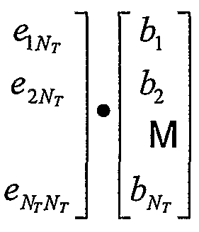
Claims
Priority Applications (5)
| Application Number | Priority Date | Filing Date | Title |
|---|---|---|---|
| JP2001569984A JP2003528527A (en) | 2000-03-22 | 2001-03-20 | High-efficiency, high-performance communication system employing multi-carrier modulation |
| BR0109422-0A BR0109422A (en) | 2000-03-22 | 2001-03-20 | High efficiency, high performance communications system employing multiport modulation |
| AU2001249344A AU2001249344A1 (en) | 2000-03-22 | 2001-03-20 | High efficiency, high performance communications system employing multi-carrier modulation |
| CA002402011A CA2402011A1 (en) | 2000-03-22 | 2001-03-20 | High efficiency, high performance communications system employing multi-carrier modulation |
| NO20024507A NO20024507D0 (en) | 2000-03-22 | 2002-09-20 | Multi-carrier modulation in a high-efficiency and high-performance connection system |
Applications Claiming Priority (2)
| Application Number | Priority Date | Filing Date | Title |
|---|---|---|---|
| US09/532,492 US20020154705A1 (en) | 2000-03-22 | 2000-03-22 | High efficiency high performance communications system employing multi-carrier modulation |
| US09/532,492 | 2000-03-22 |
Publications (2)
| Publication Number | Publication Date |
|---|---|
| WO2001071928A2 true WO2001071928A2 (en) | 2001-09-27 |
| WO2001071928A3 WO2001071928A3 (en) | 2002-05-02 |
Family
ID=24122043
Family Applications (1)
| Application Number | Title | Priority Date | Filing Date |
|---|---|---|---|
| PCT/US2001/009179 WO2001071928A2 (en) | 2000-03-22 | 2001-03-20 | High efficiency, high performance communications system employing multi-carrier modulation |
Country Status (9)
| Country | Link |
|---|---|
| US (1) | US20020154705A1 (en) |
| JP (1) | JP2003528527A (en) |
| KR (1) | KR20030036145A (en) |
| AU (1) | AU2001249344A1 (en) |
| BR (1) | BR0109422A (en) |
| CA (1) | CA2402011A1 (en) |
| NO (1) | NO20024507D0 (en) |
| TW (1) | TW533682B (en) |
| WO (1) | WO2001071928A2 (en) |
Cited By (62)
| Publication number | Priority date | Publication date | Assignee | Title |
|---|---|---|---|---|
| WO2002078211A2 (en) * | 2001-03-23 | 2002-10-03 | Qualcomm Incorporated | Method and apparatus for utilizing channel state information in a wireless communication system |
| WO2003041300A1 (en) | 2001-11-06 | 2003-05-15 | Qualcomm Incorporated | Multiple-access multiple-input multiple-output (mimo) communication system |
| EP1392004A2 (en) * | 2002-08-22 | 2004-02-25 | Interuniversitair Microelektronica Centrum Vzw | Method for multi-user MIMO transmission and apparatus suited therefore |
| EP1523812A1 (en) * | 2002-06-20 | 2005-04-20 | Lg Electronics Inc. | Improved mimo system and method for radio communication |
| EP1551127A1 (en) * | 2001-12-21 | 2005-07-06 | Mitsubishi Denki Kabushiki Kaisha | Radio communication system and transmitter for implementing frequency diversity |
| KR100518434B1 (en) * | 2002-11-05 | 2005-09-29 | 엘지전자 주식회사 | transmission method of downlink control signal for MIMO system |
| JP2005531219A (en) * | 2002-06-24 | 2005-10-13 | クゥアルコム・インコーポレイテッド | Diversity communication system for MIMO OFDM communication system |
| KR100551858B1 (en) * | 2002-12-04 | 2006-02-13 | 엘지전자 주식회사 | Method for transmitting and receiving data signal in MIMO system |
| JP2006513674A (en) * | 2002-12-11 | 2006-04-20 | クゥアルコム・インコーポレイテッド | Eigenvector derivation for spatial processing in MIMO communication systems |
| JP2006518971A (en) * | 2003-02-25 | 2006-08-17 | クゥアルコム・インコーポレイテッド | Transmission scheme for multi-antenna communication systems using multi-carrier modulation |
| JP2007503767A (en) * | 2003-08-27 | 2007-02-22 | クゥアルコム・インコーポレイテッド | Frequency independent spatial processing for broadband MISO and MIMO system background |
| AU2003270416B2 (en) * | 2002-09-10 | 2007-03-08 | Ipr Licensing Inc. | Techniques for correcting for phase and amplitude offsets in a mimo radio device |
| JP2007089144A (en) * | 2005-08-24 | 2007-04-05 | Matsushita Electric Ind Co Ltd | Mimo-ofdm transmitter and mimo-ofdm transmitting method |
| DE102005051275A1 (en) * | 2005-10-26 | 2007-05-03 | Fraunhofer-Gesellschaft zur Förderung der angewandten Forschung e.V. | Information signals transmitting device for satellite system, has orthogonal frequency-division multiplexing control stage allocating different groups of carriers, which are emitted by spatial emitters, with different information |
| US7218684B2 (en) | 2001-11-02 | 2007-05-15 | Interdigital Technology Corporation | Method and system for code reuse and capacity enhancement using null steering |
| WO2007069071A2 (en) * | 2005-01-14 | 2007-06-21 | Piping Hot Networks Limited | Dual payload and adaptive modulation |
| WO2007073116A1 (en) * | 2005-12-22 | 2007-06-28 | Electronics And Telecommunications Research Institute | Method for demodulating broadcast channel by using synchronization channel at ofdm system with transmit diversity and transmitting/receiving device therefor |
| KR100810271B1 (en) * | 2005-11-22 | 2008-03-07 | 삼성전자주식회사 | Apparatus and method for transmitting/receiving a signal in a communication system |
| EP1914917A1 (en) * | 2005-08-08 | 2008-04-23 | Huawei Technologies Co., Ltd. | A signal modulation method based on orthogonal frequency division multiple and the apparatus thereof |
| US7388920B2 (en) | 2003-05-02 | 2008-06-17 | Samsung Electronics Co., Ltd. | Apparatus and method for performing channel estimation in an orthogonal frequency division multiplexing (OFDM) system using multiple antennas |
| CN100403596C (en) * | 2001-11-29 | 2008-07-16 | 美商内数位科技公司 | Efficient multiple input multiple output system for multi-path fading channels |
| US7415074B2 (en) | 2004-01-09 | 2008-08-19 | Kabushiki Kaisha Toshiba | MIMO transmission and reception methods and devices |
| EP2003835A1 (en) * | 2007-06-15 | 2008-12-17 | Nokia Siemens Networks Oy | Method for operating a radio communication system, receiver station and radio communication system |
| US7471729B2 (en) | 2002-07-31 | 2008-12-30 | Panasonic Corporation | Multicarrier transmission apparatus and multicarrier transmission method |
| US7499393B2 (en) | 2004-08-11 | 2009-03-03 | Interdigital Technology Corporation | Per stream rate control (PSRC) for improving system efficiency in OFDM-MIMO communication systems |
| JP2009089439A (en) * | 2001-10-17 | 2009-04-23 | Nortel Networks Ltd | Synchronization in multi-carrier wave cdma system |
| KR100979657B1 (en) | 2002-09-30 | 2010-09-02 | 알카텔-루센트 유에스에이 인코포레이티드 | Signaling and control mechanisms in MIMO HARQ schemes for wireless communication systems |
| US7818018B2 (en) | 2004-01-29 | 2010-10-19 | Qualcomm Incorporated | Distributed hierarchical scheduling in an AD hoc network |
| EP2271043A3 (en) * | 2000-07-12 | 2011-03-23 | Qualcomm Incorporated | Method and apparatus for providing channel state information in a MIMO system |
| JP2011103682A (en) * | 2010-12-28 | 2011-05-26 | Fujitsu Ltd | Mobile communication system and communication method thereof, and transmission station |
| US7974243B2 (en) | 2003-06-18 | 2011-07-05 | Nippon Telegraph And Telephone Corporation | Wireless packet communication method and wireless packet communication apparatus |
| EP2267927A3 (en) * | 2002-10-25 | 2012-05-16 | Qualcomm Incorporated | Multi-mode terminal in a wireless MIMO system |
| US8194776B2 (en) | 2000-03-22 | 2012-06-05 | Qualcomm Incorporated | Multiplexing of real time services and non-real time services for OFDM systems |
| US8233462B2 (en) | 2003-10-15 | 2012-07-31 | Qualcomm Incorporated | High speed media access control and direct link protocol |
| US8270432B2 (en) | 2005-01-17 | 2012-09-18 | Broadcom Corporation | Method and system for rate selection algorithm to maximize throughput in close loop multiple input multiple output (MIMO) wireless local area network (WLAN) system |
| US8284752B2 (en) | 2003-10-15 | 2012-10-09 | Qualcomm Incorporated | Method, apparatus, and system for medium access control |
| US8315271B2 (en) | 2004-03-26 | 2012-11-20 | Qualcomm Incorporated | Method and apparatus for an ad-hoc wireless communications system |
| US8355372B2 (en) | 2004-05-07 | 2013-01-15 | Qualcomm Incorporated | Transmission mode and rate selection for a wireless communication system |
| JP2013051713A (en) * | 2003-06-30 | 2013-03-14 | Panasonic Corp | Transmission method, transmission apparatus, reception method and reception apparatus |
| US8401018B2 (en) | 2004-06-02 | 2013-03-19 | Qualcomm Incorporated | Method and apparatus for scheduling in a wireless network |
| US8462817B2 (en) | 2003-10-15 | 2013-06-11 | Qualcomm Incorporated | Method, apparatus, and system for multiplexing protocol data units |
| US8467297B2 (en) | 2005-03-10 | 2013-06-18 | Thomson Licensing | Hybrid mesh routing protocol |
| US8472473B2 (en) | 2003-10-15 | 2013-06-25 | Qualcomm Incorporated | Wireless LAN protocol stack |
| US8483105B2 (en) | 2003-10-15 | 2013-07-09 | Qualcomm Incorporated | High speed media access control |
| JP2013138437A (en) * | 2013-01-11 | 2013-07-11 | Hitachi Ltd | Transmission station and transmission method |
| US8542575B2 (en) | 2003-06-30 | 2013-09-24 | Fujitsu Limited | Multiple-input multiple-output transmission system |
| US8571132B2 (en) | 2004-12-22 | 2013-10-29 | Qualcomm Incorporated | Constrained hopping in wireless communication systems |
| US8600336B2 (en) | 2005-09-12 | 2013-12-03 | Qualcomm Incorporated | Scheduling with reverse direction grant in wireless communication systems |
| US8750151B2 (en) | 2002-10-25 | 2014-06-10 | Qualcomm Incorporated | Channel calibration for a time division duplexed communication system |
| US8842657B2 (en) | 2003-10-15 | 2014-09-23 | Qualcomm Incorporated | High speed media access control with legacy system interoperability |
| US8903440B2 (en) | 2004-01-29 | 2014-12-02 | Qualcomm Incorporated | Distributed hierarchical scheduling in an ad hoc network |
| US9013974B2 (en) | 2002-10-25 | 2015-04-21 | Qualcomm Incorporated | MIMO WLAN system |
| US9031097B2 (en) | 2002-10-25 | 2015-05-12 | Qualcomm Incorporated | MIMO system with multiple spatial multiplexing modes |
| US9042348B2 (en) | 2003-03-03 | 2015-05-26 | Hitachi, Ltd. | Data transmission method for a mobile communication system |
| US9154274B2 (en) | 2002-10-25 | 2015-10-06 | Qualcomm Incorporated | OFDM communication system with multiple OFDM symbol sizes |
| US9155106B2 (en) | 2002-10-29 | 2015-10-06 | Qualcomm Incorporated | Uplink pilot and signaling transmission in wireless communication systems |
| US9226308B2 (en) | 2003-10-15 | 2015-12-29 | Qualcomm Incorporated | Method, apparatus, and system for medium access control |
| US9871617B2 (en) | 2004-07-23 | 2018-01-16 | Qualcomm Incorporated | Method of optimizing portions of a frame |
| US9876609B2 (en) | 2003-12-01 | 2018-01-23 | Qualcomm Incorporated | Method and apparatus for providing an efficient control channel structure in a wireless communication system |
| US9967005B2 (en) | 2002-10-25 | 2018-05-08 | Qualcomm Incorporated | Pilots for MIMO communication systems |
| CN108306669A (en) * | 2017-01-11 | 2018-07-20 | 深圳市首欣通达科技有限公司 | A kind of dual mode satellite call method based on orthogonal frequency division multiplexing |
| US11683136B2 (en) | 2004-02-13 | 2023-06-20 | Neo Wireless Llc | Methods and apparatus for multi-carrier communication systems with adaptive transmission and feedback |
Families Citing this family (176)
| Publication number | Priority date | Publication date | Assignee | Title |
|---|---|---|---|---|
| US6169789B1 (en) | 1996-12-16 | 2001-01-02 | Sanjay K. Rao | Intelligent keyboard system |
| DE60021524T2 (en) * | 2000-04-18 | 2006-06-01 | Sony International (Europe) Gmbh | OFDM diversity transmission |
| ATE326794T1 (en) * | 2000-06-06 | 2006-06-15 | Lucent Technologies Inc | CODE MATCHED FILTER FOR A CDMA RADIO DIVERSITY RECEIVER |
| US8363744B2 (en) * | 2001-06-10 | 2013-01-29 | Aloft Media, Llc | Method and system for robust, secure, and high-efficiency voice and packet transmission over ad-hoc, mesh, and MIMO communication networks |
| DE60043202D1 (en) * | 2000-08-24 | 2009-12-03 | Sony Deutschland Gmbh | Communication device for transmitting and receiving OFDM signals in a radio communication system |
| US8339935B2 (en) * | 2000-09-01 | 2012-12-25 | Apple Inc. | Adaptive time diversity and spatial diversity for OFDM |
| US6985434B2 (en) * | 2000-09-01 | 2006-01-10 | Nortel Networks Limited | Adaptive time diversity and spatial diversity for OFDM |
| US6937592B1 (en) * | 2000-09-01 | 2005-08-30 | Intel Corporation | Wireless communications system that supports multiple modes of operation |
| US7342875B2 (en) * | 2000-11-06 | 2008-03-11 | The Directv Group, Inc. | Space-time coded OFDM system for MMDS applications |
| US6947748B2 (en) | 2000-12-15 | 2005-09-20 | Adaptix, Inc. | OFDMA with adaptive subcarrier-cluster configuration and selective loading |
| EP1220477A1 (en) * | 2000-12-28 | 2002-07-03 | Koninklijke Philips Electronics N.V. | Method and device to relay data in a telecommunication system |
| US7050510B2 (en) * | 2000-12-29 | 2006-05-23 | Lucent Technologies Inc. | Open-loop diversity technique for systems employing four transmitter antennas |
| US6801790B2 (en) * | 2001-01-17 | 2004-10-05 | Lucent Technologies Inc. | Structure for multiple antenna configurations |
| US7116722B2 (en) * | 2001-02-09 | 2006-10-03 | Lucent Technologies Inc. | Wireless communication system using multi-element antenna having a space-time architecture |
| US7006483B2 (en) * | 2001-02-23 | 2006-02-28 | Ipr Licensing, Inc. | Qualifying available reverse link coding rates from access channel power setting |
| KR100781969B1 (en) * | 2001-03-26 | 2007-12-06 | 삼성전자주식회사 | Data communication apparatus and method based on the Orthogonal Frequency Division Multiple Access |
| US7092450B1 (en) * | 2001-04-09 | 2006-08-15 | At&T Corp. | Frequency-domain method for joint equalization and decoding of space-time block codes |
| US7379508B1 (en) * | 2001-04-09 | 2008-05-27 | At&T Corp. | Frequency-domain method for joint equalization and decoding of space-time block codes |
| US7706458B2 (en) * | 2001-04-24 | 2010-04-27 | Mody Apurva N | Time and frequency synchronization in Multi-Input, Multi-Output (MIMO) systems |
| US7310304B2 (en) * | 2001-04-24 | 2007-12-18 | Bae Systems Information And Electronic Systems Integration Inc. | Estimating channel parameters in multi-input, multi-output (MIMO) systems |
| US7088782B2 (en) * | 2001-04-24 | 2006-08-08 | Georgia Tech Research Corporation | Time and frequency synchronization in multi-input, multi-output (MIMO) systems |
| US7209524B2 (en) * | 2001-04-27 | 2007-04-24 | The Directv Group, Inc. | Layered modulation for digital signals |
| US7583728B2 (en) | 2002-10-25 | 2009-09-01 | The Directv Group, Inc. | Equalizers for layered modulated and other signals |
| US8005035B2 (en) | 2001-04-27 | 2011-08-23 | The Directv Group, Inc. | Online output multiplexer filter measurement |
| US7042856B2 (en) * | 2001-05-03 | 2006-05-09 | Qualcomm, Incorporation | Method and apparatus for controlling uplink transmissions of a wireless communication system |
| JP2002344415A (en) * | 2001-05-14 | 2002-11-29 | Matsushita Electric Ind Co Ltd | Multi carrier communication method and apparatus |
| US7313193B2 (en) * | 2001-05-15 | 2007-12-25 | Qualcomm Incorporated | Multi–tone signal transmission methods and apparatus |
| US6662024B2 (en) | 2001-05-16 | 2003-12-09 | Qualcomm Incorporated | Method and apparatus for allocating downlink resources in a multiple-input multiple-output (MIMO) communication system |
| US7072413B2 (en) | 2001-05-17 | 2006-07-04 | Qualcomm, Incorporated | Method and apparatus for processing data for transmission in a multi-channel communication system using selective channel inversion |
| US7688899B2 (en) * | 2001-05-17 | 2010-03-30 | Qualcomm Incorporated | Method and apparatus for processing data for transmission in a multi-channel communication system using selective channel inversion |
| FR2825856B1 (en) * | 2001-06-06 | 2003-09-12 | Nortel Networks Ltd | SIGNAL PROCESSING METHOD AND DEVICE IN A SPREAD SPECTRUM RADIO COMMUNICATION RECEIVER |
| US7031754B2 (en) * | 2001-06-11 | 2006-04-18 | Kathrein-Werke Kg | Shapable antenna beams for cellular networks |
| US7440509B2 (en) * | 2001-06-21 | 2008-10-21 | Motorola, Inc. | Method and system for interference averaging in a wireless communication system |
| US7027523B2 (en) * | 2001-06-22 | 2006-04-11 | Qualcomm Incorporated | Method and apparatus for transmitting data in a time division duplexed (TDD) communication system |
| DE60218680T2 (en) * | 2001-06-27 | 2007-12-06 | Koninklijke Philips Electronics N.V. | FREQUENCY SHIFT DIVERSITY RECEIVER |
| US8116260B1 (en) * | 2001-08-22 | 2012-02-14 | At&T Intellectual Property Ii, L.P. | Simulcasting MIMO communication system |
| US20030066004A1 (en) * | 2001-09-28 | 2003-04-03 | Rudrapatna Ashok N. | Harq techniques for multiple antenna systems |
| US7277679B1 (en) * | 2001-09-28 | 2007-10-02 | Arraycomm, Llc | Method and apparatus to provide multiple-mode spatial processing to a terminal unit |
| US7158494B2 (en) * | 2001-10-22 | 2007-01-02 | Matsushita Electric Industrial Co., Ltd. | Multi-mode communications transmitter |
| US7012883B2 (en) * | 2001-11-21 | 2006-03-14 | Qualcomm Incorporated | Rate selection for an OFDM system |
| US6754169B2 (en) * | 2001-12-13 | 2004-06-22 | Motorola, Inc. | Method and system of operation for a variable transmission mode multi-carrier communication system |
| US7020110B2 (en) * | 2002-01-08 | 2006-03-28 | Qualcomm Incorporated | Resource allocation for MIMO-OFDM communication systems |
| US7079809B1 (en) * | 2002-02-07 | 2006-07-18 | Kathrein-Werke Kg | Systems and methods for providing improved wireless signal quality using diverse antenna beams |
| US7715466B1 (en) * | 2002-02-27 | 2010-05-11 | Sprint Spectrum L.P. | Interference cancellation system and method for wireless antenna configuration |
| US7042858B1 (en) * | 2002-03-22 | 2006-05-09 | Jianglei Ma | Soft handoff for OFDM |
| JP2003309533A (en) * | 2002-04-17 | 2003-10-31 | Matsushita Electric Ind Co Ltd | Wireless transmitter, wireless receiver, and method thereof |
| GB0212165D0 (en) * | 2002-05-27 | 2002-07-03 | Nokia Corp | A wireless system |
| US7200178B2 (en) * | 2002-06-12 | 2007-04-03 | Texas Instruments Incorporated | Methods for optimizing time variant communication channels |
| US7359313B2 (en) * | 2002-06-24 | 2008-04-15 | Agere Systems Inc. | Space-time bit-interleaved coded modulation for wideband transmission |
| EP1529347B1 (en) | 2002-07-03 | 2016-08-24 | The Directv Group, Inc. | Method and apparatus for layered modulation |
| US7366200B2 (en) * | 2002-08-26 | 2008-04-29 | Qualcomm Incorporated | Beacon signaling in a wireless system |
| US6985498B2 (en) * | 2002-08-26 | 2006-01-10 | Flarion Technologies, Inc. | Beacon signaling in a wireless system |
| US7133354B2 (en) * | 2002-08-26 | 2006-11-07 | Qualcomm Incorporated | Synchronization techniques for a wireless system |
| US7388845B2 (en) * | 2002-08-26 | 2008-06-17 | Qualcomm Incorporated | Multiple access wireless communications system using a multisector configuration |
| US8194770B2 (en) | 2002-08-27 | 2012-06-05 | Qualcomm Incorporated | Coded MIMO systems with selective channel inversion applied per eigenmode |
| US6940917B2 (en) * | 2002-08-27 | 2005-09-06 | Qualcomm, Incorporated | Beam-steering and beam-forming for wideband MIMO/MISO systems |
| US7889819B2 (en) * | 2002-10-04 | 2011-02-15 | Apurva Mody | Methods and systems for sampling frequency offset detection, correction and control for MIMO OFDM systems |
| US8570988B2 (en) | 2002-10-25 | 2013-10-29 | Qualcomm Incorporated | Channel calibration for a time division duplexed communication system |
| US8170513B2 (en) | 2002-10-25 | 2012-05-01 | Qualcomm Incorporated | Data detection and demodulation for wireless communication systems |
| CN101166054B (en) * | 2002-10-25 | 2013-03-06 | 高通股份有限公司 | MIMO WLAN systems |
| US8218609B2 (en) | 2002-10-25 | 2012-07-10 | Qualcomm Incorporated | Closed-loop rate control for a multi-channel communication system |
| AU2003301717A1 (en) * | 2002-10-25 | 2004-05-25 | The Directv Group, Inc. | Lower complexity layered modulation signal processor |
| US8169944B2 (en) | 2002-10-25 | 2012-05-01 | Qualcomm Incorporated | Random access for wireless multiple-access communication systems |
| US7151809B2 (en) * | 2002-10-25 | 2006-12-19 | Qualcomm, Incorporated | Channel estimation and spatial processing for TDD MIMO systems |
| US7002900B2 (en) | 2002-10-25 | 2006-02-21 | Qualcomm Incorporated | Transmit diversity processing for a multi-antenna communication system |
| US7039001B2 (en) * | 2002-10-29 | 2006-05-02 | Qualcomm, Incorporated | Channel estimation for OFDM communication systems |
| JP4197482B2 (en) * | 2002-11-13 | 2008-12-17 | パナソニック株式会社 | Base station transmission method, base station transmission apparatus, and communication terminal |
| US7724639B1 (en) * | 2002-12-12 | 2010-05-25 | Entropic Communications, Inc. | Method of bit allocation in a multicarrier symbol to achieve non-periodic frequency diversity |
| US7154960B2 (en) * | 2002-12-31 | 2006-12-26 | Lucent Technologies Inc. | Method of determining the capacity of each transmitter antenna in a multiple input/multiple output (MIMO) wireless system |
| US20040176097A1 (en) * | 2003-02-06 | 2004-09-09 | Fiona Wilson | Allocation of sub channels of MIMO channels of a wireless network |
| US7885228B2 (en) | 2003-03-20 | 2011-02-08 | Qualcomm Incorporated | Transmission mode selection for data transmission in a multi-channel communication system |
| JPWO2005008931A1 (en) * | 2003-07-16 | 2006-09-28 | 日本電気株式会社 | Transmitter, receiver, wireless communication system |
| US8824582B2 (en) | 2003-08-08 | 2014-09-02 | Intel Corporation | Base station and method for channel coding and link adaptation |
| US7321614B2 (en) * | 2003-08-08 | 2008-01-22 | Intel Corporation | Apparatus and methods for communicating using symbol-modulated subcarriers |
| US7394858B2 (en) * | 2003-08-08 | 2008-07-01 | Intel Corporation | Systems and methods for adaptive bit loading in a multiple antenna orthogonal frequency division multiplexed communication system |
| US7221680B2 (en) * | 2003-09-02 | 2007-05-22 | Qualcomm Incorporated | Multiplexing and transmission of multiple data streams in a wireless multi-carrier communication system |
| US8477809B2 (en) | 2003-09-02 | 2013-07-02 | Qualcomm Incorporated | Systems and methods for generalized slot-to-interlace mapping |
| US8509051B2 (en) | 2003-09-02 | 2013-08-13 | Qualcomm Incorporated | Multiplexing and transmission of multiple data streams in a wireless multi-carrier communication system |
| US8599764B2 (en) * | 2003-09-02 | 2013-12-03 | Qualcomm Incorporated | Transmission of overhead information for reception of multiple data streams |
| US7769097B2 (en) | 2003-09-15 | 2010-08-03 | Intel Corporation | Methods and apparatus to control transmission of a multicarrier wireless communication channel through multiple antennas |
| US7724838B2 (en) * | 2003-09-25 | 2010-05-25 | Qualcomm Incorporated | Hierarchical coding with multiple antennas in a wireless communication system |
| KR100944821B1 (en) * | 2003-10-24 | 2010-03-03 | 콸콤 인코포레이티드 | Frequency division multiplexing of multiple data streams in a wireless multi-carrier communication system |
| US8526412B2 (en) * | 2003-10-24 | 2013-09-03 | Qualcomm Incorporated | Frequency division multiplexing of multiple data streams in a wireless multi-carrier communication system |
| US7616698B2 (en) | 2003-11-04 | 2009-11-10 | Atheros Communications, Inc. | Multiple-input multiple output system and method |
| US7620028B2 (en) * | 2003-11-06 | 2009-11-17 | Atheros Communications, Inc. | Multi-channel binding in data transmission |
| FI20031668A0 (en) * | 2003-11-17 | 2003-11-17 | Nokia Corp | Transfer method and transmitter |
| US7746800B2 (en) * | 2003-11-21 | 2010-06-29 | Nokia Corporation | Flexible rate split method for MIMO transmission |
| US8027417B2 (en) | 2003-12-19 | 2011-09-27 | Nortel Networks Limited | Interference-weighted communication signal processing systems and methods |
| US7450489B2 (en) * | 2003-12-30 | 2008-11-11 | Intel Corporation | Multiple-antenna communication systems and methods for communicating in wireless local area networks that include single-antenna communication devices |
| US8611283B2 (en) | 2004-01-28 | 2013-12-17 | Qualcomm Incorporated | Method and apparatus of using a single channel to provide acknowledgement and assignment messages |
| EP1712019B1 (en) | 2004-01-29 | 2014-01-15 | Neocific, Inc. | Methods and apparatus for overlaying multi-carrier and direct sequence spread spectrum signals in a broadband wireless communication system |
| JP3923050B2 (en) * | 2004-01-30 | 2007-05-30 | 松下電器産業株式会社 | Transmission / reception apparatus and transmission / reception method |
| KR101012369B1 (en) * | 2004-02-12 | 2011-02-09 | 엘지전자 주식회사 | Method for Transmitting and Receiving Data Using Plurality of Antenna |
| EP1719265B1 (en) | 2004-02-11 | 2011-11-02 | LG Electronics Inc. | A method and system for transmitting and receiving data streams |
| US20050208949A1 (en) * | 2004-02-12 | 2005-09-22 | Chiueh Tzi-Cker | Centralized channel assignment and routing algorithms for multi-channel wireless mesh networks |
| GB2411328B (en) * | 2004-02-23 | 2007-05-16 | Toshiba Res Europ Ltd | Adaptive MIMO systems |
| CN100592648C (en) * | 2004-03-09 | 2010-02-24 | 桥扬科技有限公司 | Methods and apparatus for random access in multi-carrier communication systems |
| KR101100996B1 (en) * | 2004-03-09 | 2011-12-29 | 파나소닉 주식회사 | Random access method and radio communication terminal device |
| US7983142B2 (en) * | 2004-03-30 | 2011-07-19 | Intel Corporation | Apparatus, systems, and methods for the reception and synchronization of asynchronous signals |
| ATE372002T1 (en) * | 2004-04-22 | 2007-09-15 | France Telecom | TRANSMISSION TO CDMA COMMUNICATION SYSTEM THROUGH A MIMO CHANNEL |
| US8233555B2 (en) | 2004-05-17 | 2012-07-31 | Qualcomm Incorporated | Time varying delay diversity of OFDM |
| US20080205307A1 (en) * | 2004-06-10 | 2008-08-28 | Koninklijke Philips Electronics, N.V. | Transmitting Signals Via at Least Two Hannels Simultaneously |
| KR20050118031A (en) * | 2004-06-12 | 2005-12-15 | 삼성전자주식회사 | Apparatus and method for efficient transmission broadcasting channel utilizing cyclic delay diversity |
| US9525977B2 (en) * | 2004-06-15 | 2016-12-20 | Texas Instruments Incorporated | Broadcast multicast mode |
| US20050288062A1 (en) * | 2004-06-23 | 2005-12-29 | Hammerschmidt Joachim S | Method and apparatus for selecting a transmission mode based upon packet size in a multiple antenna communication system |
| KR100891783B1 (en) * | 2004-06-25 | 2009-04-07 | 삼성전자주식회사 | Method for transmitting and receiving data of broadcast service in a wireless communication system usign ofdma |
| US7751305B2 (en) | 2004-06-25 | 2010-07-06 | Samsung Electronics Co., Ltd. | Method for transmitting and receiving broadcast service data in an OFDMA wireless communication system |
| US7548592B2 (en) * | 2004-07-02 | 2009-06-16 | James Stuart Wight | Multiple input, multiple output communications systems |
| US7738595B2 (en) * | 2004-07-02 | 2010-06-15 | James Stuart Wight | Multiple input, multiple output communications systems |
| US7619964B2 (en) * | 2004-07-08 | 2009-11-17 | Nokia Corporation | High doppler channel estimation for OFD multiple antenna systems |
| KR20060006542A (en) * | 2004-07-16 | 2006-01-19 | 삼성전자주식회사 | Mimo transmitter for wlan system at the base of ofdm and methods thereof |
| EP2378699A3 (en) * | 2004-09-27 | 2012-08-15 | Sharp Kabushiki Kaisha | Radio transmission device |
| US7715845B2 (en) | 2004-10-14 | 2010-05-11 | Qualcomm Incorporated | Tone hopping methods and apparatus |
| US7379446B2 (en) * | 2004-10-14 | 2008-05-27 | Qualcomm Incorporated | Enhanced beacon signaling method and apparatus |
| US7813330B2 (en) * | 2004-12-03 | 2010-10-12 | Samsung Electronics Co., Ltd | Gap filler apparatus and method for providing cyclic delay diversity in a digital multimedia broadcasting system, and broadcasting relay network using the same |
| US8831115B2 (en) | 2004-12-22 | 2014-09-09 | Qualcomm Incorporated | MC-CDMA multiplexing in an orthogonal uplink |
| JP4526944B2 (en) * | 2004-12-28 | 2010-08-18 | パナソニック株式会社 | Multi-antenna communication apparatus and multiplexing method determination method |
| US8780957B2 (en) | 2005-01-14 | 2014-07-15 | Qualcomm Incorporated | Optimal weights for MMSE space-time equalizer of multicode CDMA system |
| JP4494238B2 (en) * | 2005-02-03 | 2010-06-30 | 株式会社エヌ・ティ・ティ・ドコモ | MIMO multiplex transmission apparatus and MIMO multiplex transmission method |
| AR052601A1 (en) | 2005-03-10 | 2007-03-21 | Qualcomm Inc | CLASSIFICATION OF CONTENTS FOR MULTIMEDIA PROCESSING |
| US8320499B2 (en) | 2005-03-18 | 2012-11-27 | Qualcomm Incorporated | Dynamic space-time coding for a communication system |
| US8274880B2 (en) | 2005-03-30 | 2012-09-25 | Apple Inc. | Systems and methods for OFDM channelization |
| US7929407B2 (en) | 2005-03-30 | 2011-04-19 | Nortel Networks Limited | Method and system for combining OFDM and transformed OFDM |
| JP4463723B2 (en) | 2005-04-28 | 2010-05-19 | 株式会社エヌ・ティ・ティ・ドコモ | Transmitter and transmission method |
| US7466749B2 (en) | 2005-05-12 | 2008-12-16 | Qualcomm Incorporated | Rate selection with margin sharing |
| WO2006126038A1 (en) * | 2005-05-27 | 2006-11-30 | Nokia Corporation | Assignment of sub-channels to channels in a multi transmission-channel system |
| US7630350B2 (en) * | 2005-06-06 | 2009-12-08 | Broadcom Corporation | Method and system for parsing bits in an interleaver for adaptive modulations in a multiple input multiple output (MIMO) wireless local area network (WLAN) system |
| US7630732B2 (en) * | 2005-06-14 | 2009-12-08 | Interdigital Technology Corporation | Method and apparatus for generating feedback information for transmit power control in a multiple-input multiple-output wireless communication system |
| US8358714B2 (en) | 2005-06-16 | 2013-01-22 | Qualcomm Incorporated | Coding and modulation for multiple data streams in a communication system |
| US7257376B2 (en) | 2005-06-30 | 2007-08-14 | Adaptix, Inc. | Systems and methods for making channel assignments to reduce interference and increase capacity of wireless networks |
| JP4671790B2 (en) * | 2005-07-07 | 2011-04-20 | パナソニック株式会社 | COMMUNICATION DEVICE, BASE STATION DEVICE, AND COMMUNICATION METHOD |
| US7855993B2 (en) * | 2005-08-23 | 2010-12-21 | Agere Systems Inc. | Method and apparatus for reducing power fluctuations during preamble training in a multiple antenna communication system using cyclic delays |
| KR101276797B1 (en) * | 2005-08-24 | 2013-06-20 | 한국전자통신연구원 | Base station tranmitter for mobile telecommunication system, method for that system |
| US8879635B2 (en) | 2005-09-27 | 2014-11-04 | Qualcomm Incorporated | Methods and device for data alignment with time domain boundary |
| US20070081448A1 (en) * | 2005-10-06 | 2007-04-12 | Mansoor Ahmed | Partially coherent transmission for a multi-carrier communication system |
| US8654848B2 (en) | 2005-10-17 | 2014-02-18 | Qualcomm Incorporated | Method and apparatus for shot detection in video streaming |
| US8948260B2 (en) | 2005-10-17 | 2015-02-03 | Qualcomm Incorporated | Adaptive GOP structure in video streaming |
| US7729432B2 (en) * | 2005-10-28 | 2010-06-01 | Samsung Electronics Co., Ltd. | System and method for enhancing the performance of wireless communication systems |
| CN101283536A (en) | 2005-11-04 | 2008-10-08 | 松下电器产业株式会社 | Radio transmitting apparatus, radio receiving apparatus, wireless communication method, and wireless communication system |
| KR20070108316A (en) * | 2005-12-22 | 2007-11-09 | 한국전자통신연구원 | Transmit diversity method for synchronization channel and broadcasting channel for ofdm cellular system |
| EP2456088A1 (en) | 2006-02-28 | 2012-05-23 | Rotani Inc. | Methods and apparatus for overlapping mimo antenna physical sectors |
| JP2007274048A (en) * | 2006-03-30 | 2007-10-18 | Fujitsu Ltd | Wireless communication device |
| US9131164B2 (en) | 2006-04-04 | 2015-09-08 | Qualcomm Incorporated | Preprocessor method and apparatus |
| US8351405B2 (en) * | 2006-07-14 | 2013-01-08 | Qualcomm Incorporated | Method and apparatus for signaling beacons in a communication system |
| US7974360B2 (en) | 2006-05-24 | 2011-07-05 | Qualcomm Incorporated | Multi input multi output (MIMO) orthogonal frequency division multiple access (OFDMA) communication system |
| US7787826B2 (en) * | 2006-07-14 | 2010-08-31 | Qualcomm Incorporated | Methods and apparatus for transitioning between states |
| US7804910B2 (en) | 2006-08-08 | 2010-09-28 | Adaptix, Inc. | Systems and methods for wireless communication system channel allocation using international delay distortion |
| JP5044165B2 (en) | 2006-08-14 | 2012-10-10 | 株式会社東芝 | Transmitter, receiver and method in a multi-antenna wireless communication system |
| WO2008021644A2 (en) * | 2006-08-15 | 2008-02-21 | Cisco Technology, Inc. | Method for antenna array partitioning |
| JP4869889B2 (en) * | 2006-11-29 | 2012-02-08 | 京セラ株式会社 | Base station apparatus and communication method |
| KR100874264B1 (en) * | 2006-12-01 | 2008-12-16 | 한국전자통신연구원 | Method and apparatus for multiple code word transmission / reception in SC-FDMA system |
| WO2008066349A1 (en) | 2006-12-01 | 2008-06-05 | Electronics And Telecommunications Research Institute | Method and apparatus for transmitting/receiving multiple codewords in sc-fdma system |
| KR100933161B1 (en) * | 2006-12-11 | 2009-12-21 | 삼성전자주식회사 | Method and apparatus for uplink scheduling of communication system |
| JP4858199B2 (en) * | 2007-02-02 | 2012-01-18 | 住友電気工業株式会社 | Radio communication receiving apparatus and receiving method |
| JP4461162B2 (en) * | 2007-07-02 | 2010-05-12 | 株式会社東芝 | Terminal device |
| WO2009005427A1 (en) * | 2007-07-02 | 2009-01-08 | Telefonaktiebolaget Lm Ericsson (Publ) | Adaptive modulation scheme for multipath wireless channels |
| US20090175210A1 (en) * | 2007-07-26 | 2009-07-09 | Qualcomm Incorporated | Multiplexing and transmission of multiple data streams in a wireless multi-carrier communication system |
| US8085720B2 (en) * | 2008-01-25 | 2011-12-27 | At&T Mobility Ii Llc | Channel element packing and repacking |
| US8878393B2 (en) | 2008-05-13 | 2014-11-04 | Qualcomm Incorporated | Wireless power transfer for vehicles |
| US20090284369A1 (en) * | 2008-05-13 | 2009-11-19 | Qualcomm Incorporated | Transmit power control for a wireless charging system |
| KR101582685B1 (en) * | 2008-12-03 | 2016-01-06 | 엘지전자 주식회사 | Apparatus and method of transmitting data using multiple antenna |
| US8665806B2 (en) * | 2008-12-09 | 2014-03-04 | Motorola Mobility Llc | Passive coordination in a closed loop multiple input multiple out put wireless communication system |
| US9312924B2 (en) | 2009-02-10 | 2016-04-12 | Qualcomm Incorporated | Systems and methods relating to multi-dimensional wireless charging |
| US8854224B2 (en) | 2009-02-10 | 2014-10-07 | Qualcomm Incorporated | Conveying device information relating to wireless charging |
| US20100201312A1 (en) | 2009-02-10 | 2010-08-12 | Qualcomm Incorporated | Wireless power transfer for portable enclosures |
| US8599803B1 (en) * | 2009-05-01 | 2013-12-03 | Marvell International Ltd. | Open loop multiple access for WLAN |
| JP5446671B2 (en) * | 2009-09-29 | 2014-03-19 | ソニー株式会社 | Wireless transmission system and wireless communication method |
| US8434336B2 (en) * | 2009-11-14 | 2013-05-07 | Qualcomm Incorporated | Method and apparatus for managing client initiated transmissions in multiple-user communication schemes |
| JP4782229B2 (en) * | 2010-01-29 | 2011-09-28 | 株式会社エヌ・ティ・ティ・ドコモ | Transmitter, transmission method, and mobile communication system |
| US9190718B2 (en) * | 2010-05-08 | 2015-11-17 | Maxtena | Efficient front end and antenna implementation |
| JP5296748B2 (en) * | 2010-06-30 | 2013-09-25 | 株式会社バッファロー | Transmitting apparatus and transmitting method |
| JP5383770B2 (en) * | 2011-10-21 | 2014-01-08 | 京セラ株式会社 | Base station apparatus and communication method |
| KR20130073360A (en) * | 2011-12-23 | 2013-07-03 | 한국전자통신연구원 | Data processing device of multi-carrier system and data processing method thereof |
| EP2819358B1 (en) * | 2012-06-06 | 2016-11-02 | Huawei Technologies Co., Ltd. | Multiple access method, device and system |
| US10038573B2 (en) * | 2016-05-23 | 2018-07-31 | Comtech Systems Inc. | Apparatus and methods for adaptive data rate communication in a forward-scatter radio system |
| JP7068115B2 (en) * | 2018-09-12 | 2022-05-16 | 株式会社東芝 | Wireless communication equipment, wireless communication methods and programs |
Citations (4)
| Publication number | Priority date | Publication date | Assignee | Title |
|---|---|---|---|---|
| EP0734132A2 (en) * | 1995-03-23 | 1996-09-25 | Kabushiki Kaisha Toshiba | Signal structure for multicarrier modulation, which reduces the overhead requirement |
| WO1998009381A1 (en) * | 1996-08-29 | 1998-03-05 | The Board Of Trustees Of The Leland Stanford Junior University | High capacity wireless communication using spatial subchannels |
| US6005876A (en) * | 1996-03-08 | 1999-12-21 | At&T Corp | Method and apparatus for mobile data communication |
| US6131016A (en) * | 1997-08-27 | 2000-10-10 | At&T Corp | Method and apparatus for enhancing communication reception at a wireless communication terminal |
-
2000
- 2000-03-22 US US09/532,492 patent/US20020154705A1/en not_active Abandoned
-
2001
- 2001-03-20 CA CA002402011A patent/CA2402011A1/en not_active Abandoned
- 2001-03-20 BR BR0109422-0A patent/BR0109422A/en not_active Application Discontinuation
- 2001-03-20 AU AU2001249344A patent/AU2001249344A1/en not_active Abandoned
- 2001-03-20 WO PCT/US2001/009179 patent/WO2001071928A2/en not_active Application Discontinuation
- 2001-03-20 JP JP2001569984A patent/JP2003528527A/en active Pending
- 2001-03-20 KR KR1020027012371A patent/KR20030036145A/en not_active Application Discontinuation
- 2001-03-22 TW TW090106749A patent/TW533682B/en active
-
2002
- 2002-09-20 NO NO20024507A patent/NO20024507D0/en unknown
Patent Citations (4)
| Publication number | Priority date | Publication date | Assignee | Title |
|---|---|---|---|---|
| EP0734132A2 (en) * | 1995-03-23 | 1996-09-25 | Kabushiki Kaisha Toshiba | Signal structure for multicarrier modulation, which reduces the overhead requirement |
| US6005876A (en) * | 1996-03-08 | 1999-12-21 | At&T Corp | Method and apparatus for mobile data communication |
| WO1998009381A1 (en) * | 1996-08-29 | 1998-03-05 | The Board Of Trustees Of The Leland Stanford Junior University | High capacity wireless communication using spatial subchannels |
| US6131016A (en) * | 1997-08-27 | 2000-10-10 | At&T Corp | Method and apparatus for enhancing communication reception at a wireless communication terminal |
Non-Patent Citations (1)
| Title |
|---|
| LI Y ET AL: "TRANSMITTER DIVERSITY FOR OFDM SYSTEMS AND ITS IMPACT ON HIGH-RATE DATA WIRELESS NETWORKS" IEEE JOURNAL ON SELECTED AREAS IN COMMUNICATIONS, IEEE INC. NEW YORK, US, vol. 17, no. 7, July 1999 (1999-07), pages 1233-1243, XP000834945 ISSN: 0733-8716 * |
Cited By (128)
| Publication number | Priority date | Publication date | Assignee | Title |
|---|---|---|---|---|
| US8194776B2 (en) | 2000-03-22 | 2012-06-05 | Qualcomm Incorporated | Multiplexing of real time services and non-real time services for OFDM systems |
| USRE47228E1 (en) | 2000-03-22 | 2019-02-05 | Qualcomm Incorporated | Multiplexing of real time services and non-real time services for OFDM systems |
| EP2271043A3 (en) * | 2000-07-12 | 2011-03-23 | Qualcomm Incorporated | Method and apparatus for providing channel state information in a MIMO system |
| EP2271042A3 (en) * | 2000-07-12 | 2011-03-23 | Qualcomm Incorporated | Method and apparatus for transmitting in a multi-antenna communication system |
| US7949060B2 (en) | 2001-03-23 | 2011-05-24 | Qualcomm Incorporated | Method and apparatus for utilizing channel state information in a wireless communication system |
| WO2002078211A3 (en) * | 2001-03-23 | 2003-02-27 | Qualcomm Inc | Method and apparatus for utilizing channel state information in a wireless communication system |
| US7590182B2 (en) | 2001-03-23 | 2009-09-15 | Qualcomm Incorporated | Method and apparatus for utilizing channel state information in a wireless communication system |
| US6771706B2 (en) | 2001-03-23 | 2004-08-03 | Qualcomm Incorporated | Method and apparatus for utilizing channel state information in a wireless communication system |
| US7411929B2 (en) | 2001-03-23 | 2008-08-12 | Qualcomm Incorporated | Method and apparatus for utilizing channel state information in a wireless communication system |
| WO2002078211A2 (en) * | 2001-03-23 | 2002-10-03 | Qualcomm Incorporated | Method and apparatus for utilizing channel state information in a wireless communication system |
| US8441918B2 (en) | 2001-10-17 | 2013-05-14 | Apple Inc. | System access and synchronization methods for MIMO OFDM communications systems and physical layer packet and preamble design |
| JP2009089439A (en) * | 2001-10-17 | 2009-04-23 | Nortel Networks Ltd | Synchronization in multi-carrier wave cdma system |
| US8213292B2 (en) | 2001-10-17 | 2012-07-03 | Rockstar Bidco, LP | System access and synchronization methods for MIMO OFDM communications systems and physical layer packet and preamble design |
| US8830816B2 (en) | 2001-10-17 | 2014-09-09 | Apple Inc. | System access and synchronization methods for MIMO OFDM communications systems and physical layer packet and preamble design |
| US7218684B2 (en) | 2001-11-02 | 2007-05-15 | Interdigital Technology Corporation | Method and system for code reuse and capacity enhancement using null steering |
| US8149895B2 (en) | 2001-11-02 | 2012-04-03 | Interdigital Technology Corporation | Method and system for code reuse and capacity enhancement using null steering |
| US7469021B2 (en) | 2001-11-02 | 2008-12-23 | Interdigital Technology Corporation | Method and system for code reuse and capacity enhancement using null steering |
| US8553746B2 (en) | 2001-11-02 | 2013-10-08 | Interdigital Technology Corporation | Method and system for code reuse and capacity enhancement using null steering |
| US7636573B2 (en) | 2001-11-06 | 2009-12-22 | Qualcomm Incorporated | Multiple-access multiple-input multiple-output (MIMO) communication system |
| JP2005509360A (en) * | 2001-11-06 | 2005-04-07 | クゥアルコム・インコーポレイテッド | Multiple access multiple input multiple output (MIMO) communication system |
| WO2003041300A1 (en) | 2001-11-06 | 2003-05-15 | Qualcomm Incorporated | Multiple-access multiple-input multiple-output (mimo) communication system |
| US8073067B2 (en) | 2001-11-29 | 2011-12-06 | Interdigital Technology Corporation | Method and apparatus for transferring signals in a wireless communication system |
| US7613226B2 (en) | 2001-11-29 | 2009-11-03 | Interdigital Technology Corporation | Method and apparatus for transferring signals in a wireless communication system |
| CN100403596C (en) * | 2001-11-29 | 2008-07-16 | 美商内数位科技公司 | Efficient multiple input multiple output system for multi-path fading channels |
| SG153656A1 (en) * | 2001-11-29 | 2009-07-29 | Interdigital Tech Corp | Efficient multiple input multiple output system for multi-path fading channels |
| EP1551127A1 (en) * | 2001-12-21 | 2005-07-06 | Mitsubishi Denki Kabushiki Kaisha | Radio communication system and transmitter for implementing frequency diversity |
| US7502357B2 (en) | 2001-12-21 | 2009-03-10 | Mitsubishi Denki Kabushiki Kaisha | Radio communication system and transmitter |
| EP1523812A1 (en) * | 2002-06-20 | 2005-04-20 | Lg Electronics Inc. | Improved mimo system and method for radio communication |
| EP1523812A4 (en) * | 2002-06-20 | 2010-07-07 | Improved mimo system and method for radio communication | |
| JP2005531219A (en) * | 2002-06-24 | 2005-10-13 | クゥアルコム・インコーポレイテッド | Diversity communication system for MIMO OFDM communication system |
| JP2011050074A (en) * | 2002-06-24 | 2011-03-10 | Qualcomm Inc | Diversity communication system for mimo ofdm communication system |
| KR101110955B1 (en) | 2002-06-24 | 2012-03-13 | 콸콤 인코포레이티드 | Methods and apparatus for using a number of diversity transmission modes for mimo ofdm communication systems |
| US7990841B2 (en) | 2002-06-24 | 2011-08-02 | Qualcomm, Incorporated | Diversity transmission modes for MIMO OFDM communication systems |
| US7471729B2 (en) | 2002-07-31 | 2008-12-30 | Panasonic Corporation | Multicarrier transmission apparatus and multicarrier transmission method |
| EP1392004A2 (en) * | 2002-08-22 | 2004-02-25 | Interuniversitair Microelektronica Centrum Vzw | Method for multi-user MIMO transmission and apparatus suited therefore |
| EP1392004A3 (en) * | 2002-08-22 | 2005-10-19 | Interuniversitair Microelektronica Centrum Vzw | Method for multi-user MIMO transmission and apparatus suited therefore |
| US7961809B2 (en) | 2002-08-22 | 2011-06-14 | Imec | Method and apparatus for multi-user multi-input multi-output transmission |
| AU2003270416B2 (en) * | 2002-09-10 | 2007-03-08 | Ipr Licensing Inc. | Techniques for correcting for phase and amplitude offsets in a mimo radio device |
| AU2003270416C1 (en) * | 2002-09-10 | 2008-04-24 | Ipr Licensing Inc. | Techniques for correcting for phase and amplitude offsets in a mimo radio device |
| KR100979657B1 (en) | 2002-09-30 | 2010-09-02 | 알카텔-루센트 유에스에이 인코포레이티드 | Signaling and control mechanisms in MIMO HARQ schemes for wireless communication systems |
| US10382106B2 (en) | 2002-10-25 | 2019-08-13 | Qualcomm Incorporated | Pilots for MIMO communication systems |
| US9048892B2 (en) | 2002-10-25 | 2015-06-02 | Qualcomm Incorporated | MIMO system with multiple spatial multiplexing modes |
| EP2267927A3 (en) * | 2002-10-25 | 2012-05-16 | Qualcomm Incorporated | Multi-mode terminal in a wireless MIMO system |
| US9967005B2 (en) | 2002-10-25 | 2018-05-08 | Qualcomm Incorporated | Pilots for MIMO communication systems |
| US9013974B2 (en) | 2002-10-25 | 2015-04-21 | Qualcomm Incorporated | MIMO WLAN system |
| US8750151B2 (en) | 2002-10-25 | 2014-06-10 | Qualcomm Incorporated | Channel calibration for a time division duplexed communication system |
| US9154274B2 (en) | 2002-10-25 | 2015-10-06 | Qualcomm Incorporated | OFDM communication system with multiple OFDM symbol sizes |
| US9031097B2 (en) | 2002-10-25 | 2015-05-12 | Qualcomm Incorporated | MIMO system with multiple spatial multiplexing modes |
| US9155106B2 (en) | 2002-10-29 | 2015-10-06 | Qualcomm Incorporated | Uplink pilot and signaling transmission in wireless communication systems |
| KR100518434B1 (en) * | 2002-11-05 | 2005-09-29 | 엘지전자 주식회사 | transmission method of downlink control signal for MIMO system |
| KR100551858B1 (en) * | 2002-12-04 | 2006-02-13 | 엘지전자 주식회사 | Method for transmitting and receiving data signal in MIMO system |
| JP2010213298A (en) * | 2002-12-11 | 2010-09-24 | Qualcomm Inc | Derivation of eigenvectors for spatial processing in mimo communication systems |
| JP2006513674A (en) * | 2002-12-11 | 2006-04-20 | クゥアルコム・インコーポレイテッド | Eigenvector derivation for spatial processing in MIMO communication systems |
| JP2006518971A (en) * | 2003-02-25 | 2006-08-17 | クゥアルコム・インコーポレイテッド | Transmission scheme for multi-antenna communication systems using multi-carrier modulation |
| JP4833830B2 (en) * | 2003-02-25 | 2011-12-07 | クゥアルコム・インコーポレイテッド | Transmission scheme for multi-antenna communication systems using multi-carrier modulation |
| US9042348B2 (en) | 2003-03-03 | 2015-05-26 | Hitachi, Ltd. | Data transmission method for a mobile communication system |
| US7388920B2 (en) | 2003-05-02 | 2008-06-17 | Samsung Electronics Co., Ltd. | Apparatus and method for performing channel estimation in an orthogonal frequency division multiplexing (OFDM) system using multiple antennas |
| US8989108B2 (en) | 2003-06-18 | 2015-03-24 | Nippon Telegraph And Telephone Corporation | Wireless packet communication method and wireless packet communication apparatus |
| US7974243B2 (en) | 2003-06-18 | 2011-07-05 | Nippon Telegraph And Telephone Corporation | Wireless packet communication method and wireless packet communication apparatus |
| JP2013051713A (en) * | 2003-06-30 | 2013-03-14 | Panasonic Corp | Transmission method, transmission apparatus, reception method and reception apparatus |
| US8542575B2 (en) | 2003-06-30 | 2013-09-24 | Fujitsu Limited | Multiple-input multiple-output transmission system |
| KR101137079B1 (en) * | 2003-08-27 | 2012-04-20 | 콸콤 인코포레이티드 | Frequency-independent spatial processing for wideband miso and mimo systems |
| JP2012199933A (en) * | 2003-08-27 | 2012-10-18 | Qualcomm Inc | Frequency-independent spatial processing for wideband miso and mimo systems |
| KR101092794B1 (en) * | 2003-08-27 | 2011-12-12 | 콸콤 인코포레이티드 | Frequency-independent spatial processing for wideband miso and mimo systems |
| KR101129114B1 (en) * | 2003-08-27 | 2012-03-23 | 콸콤 인코포레이티드 | Frequency-independent spatial processing for wideband miso and mimo systems |
| US7894538B2 (en) | 2003-08-27 | 2011-02-22 | Qualcomm Incorporated | Frequency-independent spatial processing for wideband MISO and MIMO systems |
| JP2007503767A (en) * | 2003-08-27 | 2007-02-22 | クゥアルコム・インコーポレイテッド | Frequency independent spatial processing for broadband MISO and MIMO system background |
| KR101236330B1 (en) | 2003-08-27 | 2013-02-22 | 퀄컴 인코포레이티드 | Frequency-independent spatial processing for wideband miso and mimo systems |
| JP2011061807A (en) * | 2003-08-27 | 2011-03-24 | Qualcomm Inc | Frequency-independent spatial processing for wideband miso and mimo systems |
| US8462817B2 (en) | 2003-10-15 | 2013-06-11 | Qualcomm Incorporated | Method, apparatus, and system for multiplexing protocol data units |
| US8582430B2 (en) | 2003-10-15 | 2013-11-12 | Qualcomm Incorporated | Method and apparatus for wireless LAN (WLAN) data multiplexing |
| US8284752B2 (en) | 2003-10-15 | 2012-10-09 | Qualcomm Incorporated | Method, apparatus, and system for medium access control |
| US8842657B2 (en) | 2003-10-15 | 2014-09-23 | Qualcomm Incorporated | High speed media access control with legacy system interoperability |
| US8233462B2 (en) | 2003-10-15 | 2012-07-31 | Qualcomm Incorporated | High speed media access control and direct link protocol |
| US8774098B2 (en) | 2003-10-15 | 2014-07-08 | Qualcomm Incorporated | Method, apparatus, and system for multiplexing protocol data units |
| US9072101B2 (en) | 2003-10-15 | 2015-06-30 | Qualcomm Incorporated | High speed media access control and direct link protocol |
| US9137087B2 (en) | 2003-10-15 | 2015-09-15 | Qualcomm Incorporated | High speed media access control |
| US9226308B2 (en) | 2003-10-15 | 2015-12-29 | Qualcomm Incorporated | Method, apparatus, and system for medium access control |
| US8483105B2 (en) | 2003-10-15 | 2013-07-09 | Qualcomm Incorporated | High speed media access control |
| US8472473B2 (en) | 2003-10-15 | 2013-06-25 | Qualcomm Incorporated | Wireless LAN protocol stack |
| US10742358B2 (en) | 2003-12-01 | 2020-08-11 | Qualcomm Incorporated | Method and apparatus for providing an efficient control channel structure in a wireless communication system |
| US9876609B2 (en) | 2003-12-01 | 2018-01-23 | Qualcomm Incorporated | Method and apparatus for providing an efficient control channel structure in a wireless communication system |
| US7415074B2 (en) | 2004-01-09 | 2008-08-19 | Kabushiki Kaisha Toshiba | MIMO transmission and reception methods and devices |
| US7519128B2 (en) | 2004-01-09 | 2009-04-14 | Kabushiki Kaisha Toshiba | MIMO transmission and reception methods and devices |
| US8903440B2 (en) | 2004-01-29 | 2014-12-02 | Qualcomm Incorporated | Distributed hierarchical scheduling in an ad hoc network |
| US7818018B2 (en) | 2004-01-29 | 2010-10-19 | Qualcomm Incorporated | Distributed hierarchical scheduling in an AD hoc network |
| US11683136B2 (en) | 2004-02-13 | 2023-06-20 | Neo Wireless Llc | Methods and apparatus for multi-carrier communication systems with adaptive transmission and feedback |
| US8315271B2 (en) | 2004-03-26 | 2012-11-20 | Qualcomm Incorporated | Method and apparatus for an ad-hoc wireless communications system |
| US8355372B2 (en) | 2004-05-07 | 2013-01-15 | Qualcomm Incorporated | Transmission mode and rate selection for a wireless communication system |
| US8401018B2 (en) | 2004-06-02 | 2013-03-19 | Qualcomm Incorporated | Method and apparatus for scheduling in a wireless network |
| US9871617B2 (en) | 2004-07-23 | 2018-01-16 | Qualcomm Incorporated | Method of optimizing portions of a frame |
| KR101297883B1 (en) | 2004-08-11 | 2013-08-19 | 인터디지탈 테크날러지 코포레이션 | Per stream rate control (psrc) for improving system efficiency in ofdm-mimo communication systems |
| KR101566958B1 (en) | 2004-08-11 | 2015-11-06 | 시그널 트러스트 포 와이어리스 이노베이션 | Per stream rate control (psrc) for improving system efficiency in ofdm-mimo communication systems |
| US7499393B2 (en) | 2004-08-11 | 2009-03-03 | Interdigital Technology Corporation | Per stream rate control (PSRC) for improving system efficiency in OFDM-MIMO communication systems |
| KR101298447B1 (en) | 2004-08-11 | 2013-08-22 | 인터디지탈 테크날러지 코포레이션 | Per stream rate control (psrc) for improving system efficiency in ofdm-mimo communication systems |
| KR101504501B1 (en) * | 2004-08-11 | 2015-03-23 | 시그널 트러스트 포 와이어리스 이노베이션 | Per stream rate control (psrc) for improving system efficiency in ofdm-mimo communication systems |
| KR101440253B1 (en) * | 2004-08-11 | 2014-09-17 | 시그널 트러스트 포 와이어리스 이노베이션 | Per stream rate control (psrc) for improving system efficiency in ofdm-mimo communication systems |
| KR101611478B1 (en) | 2004-08-11 | 2016-04-26 | 시그널 트러스트 포 와이어리스 이노베이션 | Per stream rate control (psrc) for improving system efficiency in ofdm-mimo communication systems |
| KR101611496B1 (en) | 2004-08-11 | 2016-04-12 | 시그널 트러스트 포 와이어리스 이노베이션 | Per stream rate control (psrc) for improving system efficiency in ofdm-mimo communication systems |
| US8571132B2 (en) | 2004-12-22 | 2013-10-29 | Qualcomm Incorporated | Constrained hopping in wireless communication systems |
| WO2007069071A2 (en) * | 2005-01-14 | 2007-06-21 | Piping Hot Networks Limited | Dual payload and adaptive modulation |
| CN101138167B (en) * | 2005-01-14 | 2011-09-21 | 派平霍特网络有限公司 | Method of dual payload and adaptive modulation and wireless broadband communication system |
| WO2007069071A3 (en) * | 2005-01-14 | 2007-11-01 | Piping Hot Networks Ltd | Dual payload and adaptive modulation |
| US8270432B2 (en) | 2005-01-17 | 2012-09-18 | Broadcom Corporation | Method and system for rate selection algorithm to maximize throughput in close loop multiple input multiple output (MIMO) wireless local area network (WLAN) system |
| US8467297B2 (en) | 2005-03-10 | 2013-06-18 | Thomson Licensing | Hybrid mesh routing protocol |
| EP1914917A4 (en) * | 2005-08-08 | 2008-12-24 | Huawei Tech Co Ltd | A signal modulation method based on orthogonal frequency division multiple and the apparatus thereof |
| EP1914917A1 (en) * | 2005-08-08 | 2008-04-23 | Huawei Technologies Co., Ltd. | A signal modulation method based on orthogonal frequency division multiple and the apparatus thereof |
| US9048988B2 (en) | 2005-08-24 | 2015-06-02 | Wi-Fi One, Llc | Transmission signal generation apparatus, transmission signal generation method, reception signal generation apparatus, and reception signal generation method |
| US8625718B2 (en) | 2005-08-24 | 2014-01-07 | Panasonic Corporation | Transmission apparatus, transmission method, reception apparatus, and reception method |
| US10075272B2 (en) | 2005-08-24 | 2018-09-11 | Wi-Fi One, Llc | Transmission signal generation apparatus, transmission signal generation method, reception signal apparatus, and reception signal method |
| JP2007089144A (en) * | 2005-08-24 | 2007-04-05 | Matsushita Electric Ind Co Ltd | Mimo-ofdm transmitter and mimo-ofdm transmitting method |
| US8284866B2 (en) | 2005-08-24 | 2012-10-09 | Panasonic Corporation | OFDM transmission signal generation apparatus and method, and OFDM reception data generation apparatus and method |
| US9374209B2 (en) | 2005-08-24 | 2016-06-21 | Wi-Fi One, Llc | Transmission signal generation apparatus, transmission signal generation method, reception signal apparatus, and reception signal method |
| US9838178B2 (en) | 2005-08-24 | 2017-12-05 | Wi-Fi One, Llc | Transmission signal generation apparatus, transmission signal generation method, reception signal apparatus, and reception signal method |
| US10270574B2 (en) | 2005-08-24 | 2019-04-23 | Wi-Fi One, Llc | Transmission signal generation apparatus, transmission signal generation method, reception signal apparatus, and reception signal method |
| US8600336B2 (en) | 2005-09-12 | 2013-12-03 | Qualcomm Incorporated | Scheduling with reverse direction grant in wireless communication systems |
| US9198194B2 (en) | 2005-09-12 | 2015-11-24 | Qualcomm Incorporated | Scheduling with reverse direction grant in wireless communication systems |
| US8031796B2 (en) | 2005-10-26 | 2011-10-04 | Fraunhofer-Gesellschaft Zur Foerderung Der Angewandten Forschung E.V. | Device, method and computer program for transmitting an information signal comprising several transmit signals |
| DE102005051275A1 (en) * | 2005-10-26 | 2007-05-03 | Fraunhofer-Gesellschaft zur Förderung der angewandten Forschung e.V. | Information signals transmitting device for satellite system, has orthogonal frequency-division multiplexing control stage allocating different groups of carriers, which are emitted by spatial emitters, with different information |
| US8155229B2 (en) | 2005-11-22 | 2012-04-10 | Samsung Electronics Co., Ltd. | Apparatus and method for transmitting/receiving a signal in a communication system |
| KR100810271B1 (en) * | 2005-11-22 | 2008-03-07 | 삼성전자주식회사 | Apparatus and method for transmitting/receiving a signal in a communication system |
| WO2007073116A1 (en) * | 2005-12-22 | 2007-06-28 | Electronics And Telecommunications Research Institute | Method for demodulating broadcast channel by using synchronization channel at ofdm system with transmit diversity and transmitting/receiving device therefor |
| EP2003835A1 (en) * | 2007-06-15 | 2008-12-17 | Nokia Siemens Networks Oy | Method for operating a radio communication system, receiver station and radio communication system |
| US8559534B2 (en) | 2007-06-15 | 2013-10-15 | Nokia Siemens Networks Oy | Method for data transmission within a communication system, subscriber and communication system |
| WO2008152038A1 (en) * | 2007-06-15 | 2008-12-18 | Nokia Siemens Networks Oy | Method for data transmission within a communication system, subscriber and communication system |
| JP2011103682A (en) * | 2010-12-28 | 2011-05-26 | Fujitsu Ltd | Mobile communication system and communication method thereof, and transmission station |
| JP2013138437A (en) * | 2013-01-11 | 2013-07-11 | Hitachi Ltd | Transmission station and transmission method |
| CN108306669A (en) * | 2017-01-11 | 2018-07-20 | 深圳市首欣通达科技有限公司 | A kind of dual mode satellite call method based on orthogonal frequency division multiplexing |
Also Published As
| Publication number | Publication date |
|---|---|
| BR0109422A (en) | 2004-01-13 |
| AU2001249344A1 (en) | 2001-10-03 |
| TW533682B (en) | 2003-05-21 |
| US20020154705A1 (en) | 2002-10-24 |
| KR20030036145A (en) | 2003-05-09 |
| CA2402011A1 (en) | 2001-09-27 |
| NO20024507D0 (en) | 2002-09-20 |
| WO2001071928A3 (en) | 2002-05-02 |
| JP2003528527A (en) | 2003-09-24 |
Similar Documents
| Publication | Publication Date | Title |
|---|---|---|
| USRE47228E1 (en) | Multiplexing of real time services and non-real time services for OFDM systems | |
| EP2271041B1 (en) | Method and apparatus for generating pilot signals in a MIMO system | |
| CA2690245C (en) | Method and apparatus for measuring and reporting channel state information in a high efficiency, high performance communications system | |
| US20020154705A1 (en) | High efficiency high performance communications system employing multi-carrier modulation | |
| AU2001245921A2 (en) | Method and apparatus for measuring and reporting channel state information in a high efficiency, high performance communications system | |
| AU2001245921A1 (en) | Method and apparatus for measuring and reporting channel state information in a high efficiency, high performance communications system | |
| AU2007237267B2 (en) | Method and apparatus for measuring and reporting channel state information in a high efficiency, high performance communications system | |
| AU2006201688B2 (en) | Method and apparatus for measuring and reporting channel state information in a high efficiency, high performance communications system |
Legal Events
| Date | Code | Title | Description |
|---|---|---|---|
| AK | Designated states |
Kind code of ref document: A2 Designated state(s): AE AG AL AM AT AU AZ BA BB BG BR BY BZ CA CH CN CR CU CZ DE DK DM DZ EE ES FI GB GD GE GH GM HR HU ID IL IN IS JP KE KG KP KR KZ LC LK LR LS LT LU LV MA MD MG MK MN MW MX MZ NO NZ PL PT RO RU SD SE SG SI SK SL TJ TM TR TT TZ UA UG UZ VN YU ZA ZW |
|
| AL | Designated countries for regional patents |
Kind code of ref document: A2 Designated state(s): GH GM KE LS MW MZ SD SL SZ TZ UG ZW AM AZ BY KG KZ MD RU TJ TM AT BE CH CY DE DK ES FI FR GB GR IE IT LU MC NL PT SE TR BF BJ CF CG CI CM GA GN GW ML MR NE SN TD TG |
|
| 121 | Ep: the epo has been informed by wipo that ep was designated in this application | ||
| DFPE | Request for preliminary examination filed prior to expiration of 19th month from priority date (pct application filed before 20040101) | ||
| WWE | Wipo information: entry into national phase |
Ref document number: 151398 Country of ref document: IL |
|
| WWE | Wipo information: entry into national phase |
Ref document number: 2001922556 Country of ref document: EP |
|
| WWE | Wipo information: entry into national phase |
Ref document number: 2402011 Country of ref document: CA |
|
| WWE | Wipo information: entry into national phase |
Ref document number: 2001249344 Country of ref document: AU |
|
| WWE | Wipo information: entry into national phase |
Ref document number: IN/PCT/2002/1469/CHE Country of ref document: IN |
|
| WWE | Wipo information: entry into national phase |
Ref document number: 1020027012371 Country of ref document: KR |
|
| WWE | Wipo information: entry into national phase |
Ref document number: PA/A/2002/009197 Country of ref document: MX |
|
| WWE | Wipo information: entry into national phase |
Ref document number: 018069800 Country of ref document: CN |
|
| ENP | Entry into the national phase |
Ref document number: 2001 569984 Country of ref document: JP Kind code of ref document: A |
|
| WWW | Wipo information: withdrawn in national office |
Ref document number: 2001922556 Country of ref document: EP |
|
| 122 | Ep: pct application non-entry in european phase | ||
| WWP | Wipo information: published in national office |
Ref document number: 1020027012371 Country of ref document: KR |
|
| WWW | Wipo information: withdrawn in national office |
Ref document number: 1020027012371 Country of ref document: KR |