WO2000067385A1 - ACTIVATION OF MULTIPLE xDSL MODEMS WITH POWER CONTROL MEASUREMENT - Google Patents
ACTIVATION OF MULTIPLE xDSL MODEMS WITH POWER CONTROL MEASUREMENT Download PDFInfo
- Publication number
- WO2000067385A1 WO2000067385A1 PCT/US2000/040019 US0040019W WO0067385A1 WO 2000067385 A1 WO2000067385 A1 WO 2000067385A1 US 0040019 W US0040019 W US 0040019W WO 0067385 A1 WO0067385 A1 WO 0067385A1
- Authority
- WO
- WIPO (PCT)
- Prior art keywords
- communication device
- responding
- initiating
- power
- parameters
- Prior art date
Links
Classifications
-
- H—ELECTRICITY
- H04—ELECTRIC COMMUNICATION TECHNIQUE
- H04L—TRANSMISSION OF DIGITAL INFORMATION, e.g. TELEGRAPHIC COMMUNICATION
- H04L12/00—Data switching networks
- H04L12/28—Data switching networks characterised by path configuration, e.g. LAN [Local Area Networks] or WAN [Wide Area Networks]
-
- H—ELECTRICITY
- H04—ELECTRIC COMMUNICATION TECHNIQUE
- H04L—TRANSMISSION OF DIGITAL INFORMATION, e.g. TELEGRAPHIC COMMUNICATION
- H04L5/00—Arrangements affording multiple use of the transmission path
- H04L5/14—Two-way operation using the same type of signal, i.e. duplex
- H04L5/1438—Negotiation of transmission parameters prior to communication
-
- H—ELECTRICITY
- H04—ELECTRIC COMMUNICATION TECHNIQUE
- H04L—TRANSMISSION OF DIGITAL INFORMATION, e.g. TELEGRAPHIC COMMUNICATION
- H04L1/00—Arrangements for detecting or preventing errors in the information received
- H04L1/24—Testing correct operation
-
- H—ELECTRICITY
- H04—ELECTRIC COMMUNICATION TECHNIQUE
- H04L—TRANSMISSION OF DIGITAL INFORMATION, e.g. TELEGRAPHIC COMMUNICATION
- H04L5/00—Arrangements affording multiple use of the transmission path
- H04L5/0001—Arrangements for dividing the transmission path
- H04L5/0003—Two-dimensional division
- H04L5/0005—Time-frequency
- H04L5/0007—Time-frequency the frequencies being orthogonal, e.g. OFDM(A), DMT
Definitions
- activating station - the DTE, DCE and other associated terminal equipment which originates an activation of an xDSL service activating station - the DTE, DCE and other associated terminal equipment which originates an activation of an xDSL service; answering station - the DTE, DCE and other associated terminal equipment which answers a call placed on the PSTN (GSTN); carrier set - a set of one or more frequencies associated with a PSD mask of a particular xDSL Recommendation;
- CAT3 - cabling and cabling components designed and tested to transmit cleanly to 16 MHz of communications. Used for voice and data/LAN traffic to 10 megabits per second;
- CAT5 - cabling and cabling components designed and tested to transmit cleanly to 100 MHz of communications; communication method - form of communication sometimes referred to as modems, modulations, line codes, etc.; downstream - direction of transmission from the xTU-C to the xTU-R;
- Galf - an octet having the value 81 ]6 i.e., the ones complement of an HDLC flag; initiating signal - signal which initiates a startup procedure; initiating station - DTE, DCE and other associated terminal equipment which initiates a startup procedure; invalid frame - frame that has fewer than four octets between flags, excluding transparency octets; message - framed information conveyed via modulated transmission; metallic local loop - communication channel 5, the metallic wires that form the local loop to the customer premise; responding signal - signal sent in response to an initiating signal; responding station - station that responds to initiation of a communication transaction from the remote station; session - active communications connection, measured from beginning to end, between computers or applications over a network; signal - information conveyed via tone based transmission; signaling family - group of carrier sets which are integral multiples of a given carrier spacing frequency; splitter - combination of a high pass filter and a low pass filter designed to split
- ADSL Asymmetric Digital Subscriber Line; CCITT - International Circuit and Telephone Consultative Committee;
- HSTU-C handshaking portion of the xDSL central terminal unit (xTU-C);
- NTU Network Termination Unit (Customer premise end); PBO - Power Back Off;
- VDSL Very high speed Digital Subscriber Line
- xDSL any of the various types of Digital Subscriber Lines (DSL)
- xTU-C central terminal unit of an xDSL
- xTU-R remote terminal unit of an xDSL.
- the present invention is directed to a high speed communications device, such as, for example, but not limited to, a modem, a cable modem, a xDSL modem, a satellite communication system, a point-to-point wired or wireless communication system, which includes a handshaking or initializing protocol, and in particular, to an apparatus and method that provides means to robustly select measurement procedures and robustly report the results of such measurement procedures.
- a high speed communications device such as, for example, but not limited to, a modem, a cable modem, a xDSL modem, a satellite communication system, a point-to-point wired or wireless communication system, which includes a handshaking or initializing protocol, and in particular, to an apparatus and method that provides means to robustly select measurement procedures and robustly report the results of such measurement procedures.
- each local loop used for xDSL has unique parameters, such as, for example, attenuation, interference, crosstalk, etc, it is desirable to accurately measure those parameters before blindly transmitting large amounts of power into the loop.
- each xDSL scheme has used it's own proprietary style of power measurement and control, with ⁇ 'arying degrees of measurement and control.
- the ITU-T has published recommended methods for initiating data communication over voice band channels.
- the following three Recommendations have been produced, the subject matter of which is expressly incorporated herein by reference in their entirety:
- DCEs Data Circuit-Terminating Equipments
- DTEs Data Terminal Equipments
- document (3) is the final version of Temporary Document MA-006 that was published in March, 1999.
- an object of the present invention is to provide a uniform power measurement procedure that can be used for all xDSL schemes.
- Another object of the instant invention is to perform the uniform power measurement procedure prior to the selection of the specific xDSL scheme.
- the procedure of the instant invention may be implemented as an extension to an xDSL handshaking and selection procedure, such as, but not limited to, that shown in commonly assigned U.S. Patent Application Nos. 09/217,556 filed on December 21, 1998 and/or 09/281 ,813 filed on March 31 , 1999, and/or ITU-T Recommendation G.994.1 , published in June, 1999.
- Integrating the power control and measurement procedure with the xDSL selection procedure allows a more accurate selection of the particular xDSL modulation scheme, based on the power measurement results.
- the present invention also allows for a more accurate determination of the minimum needed frequency dependent transmission power during a data transmission mode.
- an apparatus for determining transmission parameters while initializing a communication link.
- a parameter indicating device that is associated with an initiating communication device, transmits first transmission parameters that can be used by the responding communication device to a responding communication device.
- a measurement receiving section that is associated with the initiating communication device, receives first signals issued by the responding communication device.
- the initiating communication device also includes a parameter receiving device that receives, from the responding communication device, second transmission parameters that can be used by the initiating communication device, and a measurement transmission section that transmits second signals to the responding communication device, in response to the received second transmission parameters.
- the responding communication device additionally includes a parameter indicating device that transmits second transmission parameters to be used by the initiating communication device to said initiating communication device.
- the first transmission parameters are related to at least one of a power level, a frequency bandwidth, a duration, and a carrier density of the communication link.
- the responding communicating device also includes a measurement receiving section that receives transmitted signals, so that the initiating communication device and the responding communication device can perform an exchange of information between respective measurement receiving sections.
- an apparatus for determining transmission parameters while initializing a communication link.
- a parameter receiving device that is associated with an initiating communication device receives transmission parameters that can be used by the initiating communication device.
- a measurement transmission section that is associated with the initiating communication device transmits signals to the responding communication device, in response to the received transmission parameters.
- the responding communication device also includes a parameter indicating device that transmits, to the initiating communication device, the transmission parameters that can be used by the initiating communication device.
- the transmission parameters are related to at least one of a power level, a frequency bandwidth, a duration, and a carrier density of the communication link.
- the responding communicating device also includes a measurement receiving section that receives the transmitted signals, the initiating communication device and the responding communicating device performing an exchange of information between respective measurement receiving sections.
- Another object of the present invention is the disclosure of an apparatus for establishing a communication link using a determined amount of transmission power.
- a parameter indicating device that is associated with an initiating communication device transmits, to a responding communication device, first transmission parameters that can be used by the responding communication device.
- a measurement receiving section that is associated with the initiating communication device receives first signals issued by the responding communication device in response to the first transmission parameters. Then, a selecting device that is associated with the initiating communication device transmits, to the responding communication device, power level parameters that can be used by the responding communication device.
- An advantage of the invention is that a parameter receiving device that is associated with the initiating communication device receives, from the responding communication device, second transmission parameters that can be used by the initiating communication device.
- a measurement transmission section that is associated with the initiating communication device transmits second signals to the responding communication device, and a selecting device, associated with the responding communication device, transmits, to the initiating communication device, power level parameters that can be used by the initiating communication device.
- Another advantage of the invention is the inclusion of a configuring device that is associated with the initiating communication device. The configuring device sets power level transmission characteristics to be used by the initiating communication device in response to the transmitted power level parameters.
- a still further advantage of the invention is that the initiating communication device and the responding communication device perform a communication link startup procedure after the power level parameter is selected.
- Another object of the present invention relates to an apparatus for establishing a communication link using a determined amount of transmission power.
- a parameter receiving device associated with an initiating communication device, receives, from a responding communication device, transmission parameters that can be used by the initiating communication device.
- a measurement transmission section associated with an initiating communication device, transmits signals to a measurement receiving section of a responding communication device, in response to the transmission parameters.
- a selecting device associated with the responding communication device, transmits, to the initiating communication device, power level parameters that can be used by the initiating communication device.
- a configuring device that is associated with the initiating communication device may additionally be provided to set power level transmission characteristics to be employed.
- a feature of the invention is that the initiating communicating device and the responding communicating device perform a communication link startup procedure after the power level parameter is selected.
- a still further object of the invention concerns a method for determining an amount of transmission power to use while establishing a communication link.
- An initiating communication device transmits a power measurement signal to a responding communication device.
- the responding communication device acknowledges reception of the power measurement signal, and additionally transmits to the initiating communication device, received power measurement values.
- the responding communication device the indicates transmission characteristics of the initiating communication device to the initiating communication device.
- the initiating communication device then utilizes the transmission characteristics received from the responding device during a subsequent transmission.
- the responding communication device may additionally transmit a signal to the initiating communication device proposing transmission characteristics of the power measurement signal to be received by the responding communication device.
- a communication link startup procedure may also be initiated after the transmission characteristics has been indicated.
- At least one of an initiation, a parameter, a result, and an acknowledgment is transmitted by digital messages. Additionally, at least a portion of the digital messages may be transmitted at substantially a same time as the power measurement signal.
- a method is disclosed for determining frequency dependent amounts of transmission power to use while establishing a communication link. According to the method, an initiating communication device transmits a power measurement signal with characteristics that are frequency dependent to a responding communication device. The responding communication device indicates the frequency dependent transmission characteristics of the initiating communication device to the initiating communication device. The initiating communication device then utilizes the frequency dependent transmission characteristics received from the responding communication device during a subsequent transmission.
- the responding communication device transmits frequency dependent received power measurement values to the initiating communication device.
- the responding communication device transmits a signal that proposes the frequency dependent transmission characteristics of the power measurement signal to be received by the responding communication device, to the initiating communication device.
- a further object of the invention pertains to a method for determining an amount of transmission power to use while establishing a communication link. A power measurement signal is transmitted from an initiating communication device to a responding communication device, in which the power measurement signal is transmitted at a predetermined power level.
- the power measurement signal is re-transmitted at incrementally higher power levels (such as, for example, 2 db increments), which may be at predetermined time intervals such as, for example, 200 ms), until the responding communication device issues a signal representing that the power measurement signal was adequately received.
- a transmit power level is then set for establishing a communication link between the initiating communication link and the responding communication device in response to the signal representing that the power measurement signal was adequately received.
- a communication link startup procedure may be initiated after the transmit power level parameter has been set.
- the transmitted power measurement signal may be encoded as digital messages on a negotiation and control channel that is exchanged between the initiating communication device and the receiving communication device.
- An additional object of the invention concerns an apparatus for measuring frequency dependent power during handshaking of a communication link.
- An indicating device that is associated with an initiating communication device transmits frequency band transmission parameters (that can be used by the responding communication device), to a responding communication device.
- a measurement transmission section that is associated with an initiating communication device transmits (to a measurement transmission section of a responding communication device) first signals in such a manner that a power level varies by frequency bands.
- a measurement receiving section of the initiating communication device receives second signals, in which the power level varies by frequency bands issued by a measurement transmission section of the responding communication device, with the second signals being received in response to the transmitted first signals.
- the first signals may be shaped by a frequency band transmission device that functions to shape the first signals by at least one of a flat filter, a sloped filter, and a b-spline filter.
- the transmitted first signals may be subjected to parameterized templates, so as to allow a non-linear gain.
- Another method for establishing communication transmission parameters during a communication link initialization, by transmitting, by an initiating communication device (such as, for example, an xTU-R) , a first digital message having parameters for a downstream power measurement sequence; transmitting, by a responding communication device (such as, for example, an xTU-C), a second digital message having parameters for an upstream power measurement sequence, and also including substantially the same said parameters of said first digital message as parameters of said second digital message; transmitting, by the initiating communication device, a third digital message that acknowledges the parameters and a mode selected by the responding communication device; transmitting, by the initiating communication device, a power measurement signal that employs the parameters; transmitting, by the responding communication device, the power measurement signal that employs the parameters; transmitting, by the initiating communication device, a fourth digital message containing a result of the power measurement signal transmitted by the responding communication device and a desired power reduction level; transmitting, by the responding communication device, a fifth digital message containing a result of the power measurement signal transmitted by the
- Fig. 1 illustrates a block diagram of a data communication system using a modem device according to an embodiment of the present invention
- Fig. 2 illustrates a detailed block diagram of a data communication system of Fig. 1;
- Fig. 3 illustrates a Power Management Exchange (PME) full duplex transaction using new message types and transactions according to the present invention
- Fig. 4 illustrates a PME half duplex transaction using new message types and transactions according to the instant invention
- Fig. 5 illustrates a Power Measurement Modulation Session (PMMS) of the instant invention using existing messages and transactions with a predetermined set of parameters for the measurement signal;
- PMMS Power Measurement Modulation Session
- Fig. 6 illustrates the PMMS session using existing messages and transactions with explicitly requested parameters for the measurement signals
- Fig. 7 illustrates the PMMS session using existing messages and transactions in which the measurement signal is stepped from a low power to a high power with a predetermined set of parameters for the measurement signal;
- Fig. 8 illustrates the PMMS session using existing messages and transactions in which the measurement signal is stepped from a low power to a high power, using explicitly requested parameters for the measurement signals;
- Fig. 9 illustrates the PMMS session using a message MR-P that is derived from existing messages and transactions for Power Back Off (PBO);
- Fig. 10 illustrates another example of the PMMS session using a message MR-P that is derived from existing messages and transactions, in which signals are transmitted to measure for PBO;
- Fig. 11 illustrates a state diagram for a handshaking portion of an xDSL remote terminal unit (HSTU-R) in which the instant invention is incorporated;
- HTU-R xDSL remote terminal unit
- Fig. 12 illustrates a state diagram for a handshaking portion of an xDSL central terminal unit (HSTU-C) in which the instant invention is incorporated;
- HTU-C xDSL central terminal unit
- Fig. 13 illustrates a dividing of signals associated with the PMMS session into a plurality of frequency bands
- Fig. 14 illustrates a flat template that shapes a transmit spectrum of a frequency band
- Fig. 15 illustrates a sloped template that shapes a transmit spectrum of a frequency band
- Figs. 16 and 17 illustrate B-Spline templates that shape a transmit spectrum of a frequency band.
- PMMS/PME uses digital messages to initiate and configure signals for measuring power for communication devices, to report measurement results, and/or to set power transmission parameters for subsequent transmissions.
- the functionality and methodology of using the PMMS and/or PME messages and procedures can also be applied to handshake procedures other than ITU-T Recommendation G.994.1, such as, but not limited to, for example, ITU-T Recommendations V.8 and V.8bis.
- a data communication system comprises a central office system 2 and a remote system 4, which are interfaced together via a communication channel 5, as shown in Fig. 1.
- the central office system 2 includes a main distribution frame (MDF) 1 that functions to interface the central office system 2 to the communication channel 5.
- the main distribution frame (MDF) 1 operates to connect, for example, telephone lines (e.g., communication channel 5) coming from the outside, on one side, and internal lines (e.g., internal central office lines) on the other side.
- the remote system 4 includes a network interface device (NID) 3 that functions to interface the remote system 4 to the communication channel 5.
- the network interface device (NID) 3 interfaces the customer's equipment to the communications network (e.g., communication channel 5). It is understood that the present invention may be applied to other communications devices without departing from the spirit and/or scope of the invention.
- Fig. 2 illustrates a detailed block diagram of the data communication system of Fig. 1.
- This communication system represents a typical installation, in which both the central office system 2 and the remote system 4 implement the instant invention.
- the central office system 2 comprises a low pass filter 34 and a high pass filter 38, a test negotiation block 46, a high speed data receiving section 68, a high speed data transmitting section 70, and a computer 82.
- Computer 82 is understood to be a generic interface to network equipment located at the central office.
- Test negotiation block 46 performs all of the negotiation and examination procedures which takes place prior to the initiation of an actual high speed data communication.
- the low pass filter 34 and high pass filter 38 function to filter communication signals transferred over the communication channel 5.
- the test negotiation block 46 tests and negotiates conditions, capacities, etc. of the central office system 2, the remote system 4, and the communication channel 5. The procedures of the test negotiation block 46 are completed prior to, and initiate the selection of the high speed modem receiving and transmitting sections
- the high speed receiving section 68 functions to receive high speed data transmitted from the remote system 4, while the high speed data transmitting section 70 transmits high speed data to the remote system 4.
- the high speed sections 68 and 70 may comprise, but not be limited to, for example, ADSL, HDSL, SHDSL, VDSL, CDSL modems.
- High speed sections 68 and 70 can be a plurality of high speed transmission devices which "share" the common block 46 during the initial negotiation procedure.
- the negotiation data receiving section 52 and the high speed data receiving section 68 transmit signals to computer 82.
- the negotiation data transmitting section 54 and the high speed data transmitting section 70 receive signals issued from the computer 82.
- Test negotiation block 46 comprises a negotiation data receiving section 52 and a negotiation data transmitting section 54.
- the negotiation data receiving section 52 receives negotiation data, while the negotiation data transmitting section 54 transmits negotiation data.
- the operation of the various sections of the central office system 2 will be described, in detail, below.
- Remote system 4 comprises a low pass filter 36, a high pass filter 40, a test negotiation block 48, a high speed data receiving section 72, a high speed data transmitting section 66, and a computer 84.
- Computer 84 is understood to be a generic interface to network equipment located at the remote system.
- Test negotiation block 48 performs all of the negotiation and examination procedures that take place prior to the actual high speed data communication.
- the low pass filter 36 and high pass filter 40 operate to filter communication signals transferred over the communication channel 5.
- the test negotiation block 48 tests and negotiates conditions, capacities, etc. of the central office system 2, the remote system 4, and the communication channel 5.
- the high speed receiving section 72 functions to receive high speed data transmitted from the central office system 2, while the high speed data transmitting section 66 transmits high speed data to the central office system 2.
- the negotiation data receiving section 56 and the high speed data receiving section 72 transmit signals to the computer 84.
- the negotiation data transmitting section 50 and the high speed data transmitting section 66 receive signals issued from the computer 84.
- the test negotiation block 48 comprises a negotiation data receiving section 56 and a negotiation data transmitting section 50.
- the negotiation data receiving section 56 receives negotiation data, while the negotiation data transmitting section 50 transmits negotiation data.
- the negotiation data transmitting section 50 of the remote system 4 transmits the upstream negotiation data to the negotiation data receiving section 52 of the central system 2.
- the negotiating data transmitting section 54 of the central system 2 transmits the downstream negotiating data to the negotiation data receiving section 56 of the remote system 4.
- the central office system 2 includes a plurality of channels 6, 10, 14, 16 and 18 that are used to communicate with a plurality of channels 22, 26, 28, 30 and 32 of the remote system 4.
- channel 6 comprises a central voice channel that is used to directly communicate with a corresponding remote voice channel 32 in a conventional voice band (e.g., 0 Hz to approximately 4 kHz), which has been filtered by low pass filters 34 and 36.
- a remote voice channel 33 is provided in the remote system 4 that is not under the control of the central office system 2.
- Remote voice channel 33 is connected in parallel with the communication channel 5 (but prior to the low pass filter 36), and thus, provides the same service as the remote voice channel 32. However, since this channel is connected prior to the low pass filter 36, the remote voice channel 33 contains both the high speed data signal and a voice signal.
- the filters may be arranged to have different frequency characteristics, so that a communication may take place using other, low band communication methods, such as, for example, ISDN, between voice channels 6 and 32.
- the high pass filters 38 and 40 are selected to ensure a frequency spectrum above 4 kHz. It is noted that some systems do not require, nor implement, some (or all) of the filters 34, 36, 38, and 40.
- Bit streams 10, 14, 16 and 18 (in the central office system 2) and bit streams 22, 26, 28 and 30 (in the remote system 4) comprise digital bit streams that are used to communicate between the central computer 82 and the remote computer 84, respectively. It is understood that it is within the scope of the present invention that bit streams 10, 14, 16, and 18 could be implemented as discrete signals (as shown), or bundled into an interface, or cable, or multiplexed into a single stream, without changing the scope and/or function of the instant invention.
- bit streams 10, 14, 16 and 18 may be configured as (but are not limited to) an interface conforming to a RS-232, parallel, Fire Wire (IEEE- 1394), Universal Serial Bus (USB), wireless, or infrared (IrDA) standard.
- bit streams 22, 26, 28 and 30 can be implemented as discrete signals (as shown in the drawings), or bundled into an interface, or cable, or multiplexed into a single stream, as described above.
- Negotiation data (e.g., control information) corresponding to the condition of the communication line (e.g., frequency characteristics, noise characteristics, presence or absence of a splitter, etc.), capabilities of the equipment, and user and application service requirements is exchanged between the negotiation data receiving section 52 and negotiation data transmitting section 54 of the central office system 2, and the negotiation data receiving section 56 and negotiation data transmitting section 50 of the remote system 4.
- condition of the communication line e.g., frequency characteristics, noise characteristics, presence or absence of a splitter, etc.
- test negotiation blocks 46 and 48 which test and negotiate the conditions, capabilities, etc. of the central office system 2, the remote system 4, and the communication channel 5.
- test negotiation blocks 46 and 48 are embedded within modems 42 and 44. However, the functionality of test negotiation blocks 46 and 48 may, alternatively, be implemented separate and distinct from the modems 42 and 44. Signals transmitted and received between the test negotiation blocks 46 and 48 are used for testing the environment itself as well as communicating the results of the tests between the central office system 2 and the remote system 4.
- PSTN voice band PSTN voice band.
- Some of the newer communication methods typically attempt to use the frequency spectrum above 4 kHz for data communication.
- the first frequency where transmission power is allowed occurs at approximately 25 kHz.
- any frequency may be used.
- tone bursts at a frequency of 34.5 kHz are used to initiate T1E1 T1.413 ADSL modems.
- that frequency should be avoided in the spectrum used by precursor negotiation methods.
- the communication paths are defined in pairs, one path for an upstream communication from the remote system 4 to the central office system 2, and another path for a downstream communication from the central office system 2 to the remote system 4.
- the negotiation upstream bits are transmitted by the negotiation data transmitting section 50 of the remote system 4, and received by the negotiation data receiving section 52 of the central office system 2.
- the negotiation downstream bits are transmitted by the negotiation data transmitting section 54 of the central office system 2, and received by the negotiation data receiving section 56 of the remote system 4.
- Messages are sent with one or more carriers, using, for example, a Differential (Binary) Phase Shift Keying (DPSK) modulation.
- DPSK Differential Phase Shift Keying
- the transmit point is rotated 180 degrees from the previous point if the transmit bit is a 1, and the transmit point is rotated 0 degrees from the previous point if the transmit bit is a 0.
- Each message is preceded by a point at an arbitrary carrier phase.
- the frequencies of the carriers, and the procedures for starting the modulation of carriers and messages, will be described below.
- Carriers are typically selected so as to be different for the upstream and downstream paths, avoid existing system activation tones, be reasonably robust against inter-modulation products, have sufficient spacing, etc.
- the transmission of the negotiation downstream data is stopped.
- the remote system 4 detects the loss of energy (carrier) from the central office system 2, the remote system 4 stops transmitting the negotiation upstream data.
- the negotiated communication method begins it's initialization procedures.
- one of the central office or remote systems When initiating a high speed communication session, one of the central office or remote systems transmits signals that are received by the opposite system that responds by transmitting predetermined signals, such as, for example, signals required in a handshake session. These signals compromise one of a half duplex or full duplex start-up procedure.
- An example of such a start-up procedure is described in Applicant's Application No. 09/473,683, filed on December 29, 1999, the disclosure of which is expressly incorporated by reference herein in its entirety.
- the start-up procedure establishes a bi-directional communication channel for use by a handshake session.
- Other examples of handshake sessions include, but are not limited to, ITU-T Recommendations V.8, V.8bis, and G.994.1 (formerly refe ⁇ ed to as
- Each transaction consists of one (or more) messages that contain data and/or requests, and then concludes with an acknowledgment message (or, alternatively, a negative-acknowledgment message).
- the messages include, but are not limited to, mode select, capabilities exchange, requests to defer, requests for power management procedures and the results of those processes.
- the unit responding to a message indicates an acceptance (with an acknowledgment message), a rejection (with a negative-acknowledgment message), or a desire to initiate a different type of message with a request message.
- a unit may initiate another transaction or terminate the handshake session.
- An acknowledgment to a mode selection message will cause the handshake session to be terminated, and the communication mode selected in the mode selection message to be initiated, using known techniques.
- messages use the frame structure set forth in ITU-T Recommendation G.994.1, noted above. However, it is understood that alternative frame structures can be employed without departing from the spirit and/or scope of the invention.
- the information content of the messages must be encoded in a consistent, scalable, and extensible manner so as to promote interoperability among equipment and compatibility with future equipment and services.
- the prior art e.g., V.8, V.8bis
- V.8, V.8bis provides general examples of means to frame and format handshaking data.
- Handshaking for xDSL modems also require the transmission of new data types, such as variables and multiple resolution parameters. Examples of encoding mechanism are given below in Tables 2 through 4. Specific names and encodings of parameters are dependent on the particular high speed communication system being used.
- Table 2 illustrates the format for encoding a small integer variable:
- Table 3 illustrates the format for encoding a variable with a range larger than the number of bits:
- Table 4 illustrates the format for encoding a parameter with multi-resolutions. Bit 6 is used to indicate a multiplying factor for bits 1 through 5. Additionally, a special code is used to indicate a data rate that is not a multiple of 32 kbit/sec (or 64 kbit/sec).
- a first embodiment is described in the context of a new transaction to an xDSL startup mechanism (such as, but not limited to, for example, ITU-T Recommendation G.994.1, noted above).
- the new transaction is refe ⁇ ed to as "Power Management Exchange” (PME).
- PME Power Management Exchange
- the functionality and methodology of the PME is the same for other handshake procedures, such as, but not limited to, for example, ITU-T Recommendations V.8 and V.8bis.
- Table 5 illustrates the new transaction presented in conjunction with a full duplex modulation negotiation communication channel, and assumes that the first message is always sent by the HSTU-R.
- the HSTU-R transmits the power management signal PM R if it was requested by the HSTU-C.
- the nature of the power measurement signals PM R and PM C are such that they do not interfere with the simultaneous transmission of the digital negotiation and control channels.
- Parameters that describe PM R and PM C include bandwidth, duration, power levels, density of carriers, etc.
- Table 6 illustrates the new transaction in conjunction with a half duplex modulation negotiation communication channel.
- the first message is always sent by the HSTU-R.
- the test signals PM C and PM R do not need to be sent concu ⁇ ently with messages.
- the instant invention also permits manufacturers to utilize their own proprietary signals that are transmitted instead of using standard signals PM R and PM C .
- the use of the proprietary signal is indicated in messages PRR and PCR.
- the Power Management Exchange comprises two types of elements: (1) digital negotiation and control channels; and (2) power measurement signals. Parameters that describe power measurement signals are negotiated and indicated as messages in the negotiation and control channels of the PME. After the power measurement signals are received and analyzed, prefe ⁇ ed transmit levels are indicated in messages to the opposite side. A PME transaction initially transmits the power measurement signals at the lowest possible level. The PME transaction may be repeated at incrementally higher power levels if the signals were not adequately received.
- Loop attenuation and minimum necessary transmit power is calculated by subtracting the measured receive power of the signals from the transmit power indicated in the messages of the PME.
- the functionality and methodology of using the PME procedure can also be applied to other handshake procedures such as but not limited to ITU-T Recommendations V.8 and V. ⁇ bis.
- a PME full duplex transaction of this embodiment co ⁇ esponds to the transaction listed in Table 5, above, and illustrated in Fig. 3.
- the parameters are encoded in digital messages on the negotiation and control channels that are exchanged between the HSTU-R and HSTU-C.
- PM X bandwidth is indicated by setting nonzero power levels on the desired carriers in the spectrum of interest. Although a prescribed number of carriers are defined, the density of the carriers can be reduced by setting the transmit power level of individual carriers to zero.
- the power level of each carrier is encoded by bits that include codes for zero and nominal power.
- the requested measurement duration is encoded in a time expressed in milliseconds.
- the HSTU-R makes power measurements based on the signals in PI and PM C .
- the signals in PI are the carriers of the HSTU-C message modulation.
- the minimum number of carriers is based upon the types of xDSL modems (e.g., ADSL, SDL, CDSL, HDSL, VDSL, etc.) included in a particular communication loop.
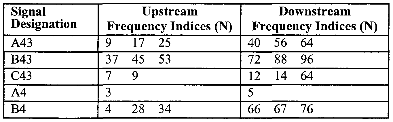
- HSTU-C message modulation carriers are shown in the last column of Tables 7 and 8, below.
- PM C allows measurement of the power of the downstream spectrum in areas outside of the carriers of PI.
- PI is composed from carriers in at least one of A43, B43, C43, and A4.
- PM C is composed from P4 and V128 carriers, or P43 and VI 38 carriers. Carrier sets are described in Tables 7 through 10, below.
- the HSTU-C makes power measurements based on the signals in P2 and PM R .
- the signals in P2 are the carriers of the HSTU-R message modulation. The minimum number of carriers is based upon the types of xDSL modems included in a particular embodiment of the mvention. HSTU-R message modulation carriers are shown in the middle column of Tables 7 and 8, below.
- PM R allows measurement of the power of the upstream spectrum in areas outside of the carriers of P2.
- P2 is composed from carriers in at least one of A43, B43, C43, and A4.
- PM R is composed from P4 and VI 28 ca ⁇ iers or P43 and VI 38 carriers.
- a carrier indexing method is used for the band which occupies the spectrum up to approximately 1.1 MHz (typically refe ⁇ ed to as the ADSL band).
- a carrier indexing method is used for the band from approximately 1.1 MHz through approximately 30 MHz (typically refe ⁇ ed to as the VDSL band), an indexing method is also used, but the carriers have a spacing of 128.0 kHz or 138.0 kHz.
- the VDSL band carrier spacing is 32 times the ADSL band carrier spacing to roughly scale the approximately 27 times bandwidth increase. It is noted that the first eight indices of the VDSL band carriers are not used because they overlap the ADSL band carriers.
- the V128 set of carriers shown in Table 9, above, is for systems that prefer 4.0 kHz spacing.
- the V138 set of carriers shown in Table 10, above, is for systems that prefer 4.3125 kHz spacing.
- the spacing of the carriers is selected to be approximately 1.2 times the previous carrier. This allows a non-linear set of carriers that scales equivalent with frequency.
- Power levels are expressed in 3 bits, as shown in Table 11, below.
- the power level for each carrier in the ADSL 4.3125 kHz band is coded in Table 12, below.
- the power level for each carrier in the ADSL 4.0 kHz band is coded in Table 13, below.
- the power level for each carrier in the VDSL band is coded in Table 14.
- VDSL band power measurement carriers are effective for all types of VDSL band modulation schemes, including, but not limited to, single-carrier modulation schemes, and multi-carrier modulation schemes. It is noted that other carrier spacings and widths may be used without departing from the spirit and/or scope of this invention.
- test signals PM CH and PM RH do not need to be sent concu ⁇ ently with messages.
- the PME half duplex transaction is listed in Table 19, below, and illustrated in Fig. 4.
- the first message is assumed to always be sent by the HSTU-R.
- the following discussion assumes that the band descriptions provided above apply.
- the nature of the power measurement signals PM RJ J and PM CH are allowed complete freedom, as they need not be concerned with the simultaneous transmission of the digital negotiation and control channels.
- Parameters that describe PM RH and PM CH include bandwidth, duration, power levels, density of ca ⁇ iers, etc.
- the HSTU-R makes a power measurement based on the signals in PM CH .
- the minimum number of carriers is based upon the types of xDSL modems included in a particular communication system.
- PM CH comprises carriers from at least one of A43, B43, C43, A4, P4 or P43, and V128 or V138 carriers shown in Tables 7 through 10, above.
- the HSTU-C makes the power measurement based on the signals in PM RH .
- the minimum number of carriers is based upon the types of xDSL modems included in a particular communication system.
- PM RH comprises carriers from at least one of A43, B43, C43, A4, P4 or P43, and V128 or V138 carriers shown in Tables 7 through 10, above.
- Non Standard (NS) request 0
- the present invention allows manufacturers to utilize (generate) their own proprietary signals that are transmitted (sent) instead of PM R and PM C (or FM m and PM CH ), while retaining a uniform negotiation and indication structure as the defined test signals.
- the use of the proprietary power measurement signal is indicated in messages PRR and PCR by setting the Non-Standard request to 1, as shown in Tables 26 and 29, below.
- Tables 27 and 30, below illustrate that the parameters of the transmitted signals are indicated using a private (e.g., proprietary) encoding scheme.
- the parameter and acknowledge messages shown in Tables 28 and 31, below, are the same as Tables 22 and 25 in the half duplex modulation negotiation communication channel, discussed above.
- a third embodiment of the invention will now be described as procedures for a session comprising existing messages (e.g. MS, MR) and transactions for the digital control provided to request the transmission of the power measurement modulation session signals.
- the MS message includes explicit details on the parameters of a desired signal (e.g., PM CH ) to be transmitted. It is noted that the following discussion may be implemented using either full duplex or half duplex modulation procedures.
- the PMMS initially sends the power measurement signals at the lowest possible power level, which may be repeated at higher power levels if the signals were not adequately received.
- the invention is not limited to an initial transmission using the lowest possible power level; that is, the initial transmission may be initiated using any desired, predetermined power level.
- the following description of the PMMS is provided with respect to a fixed set of prefabricated measurement signals.
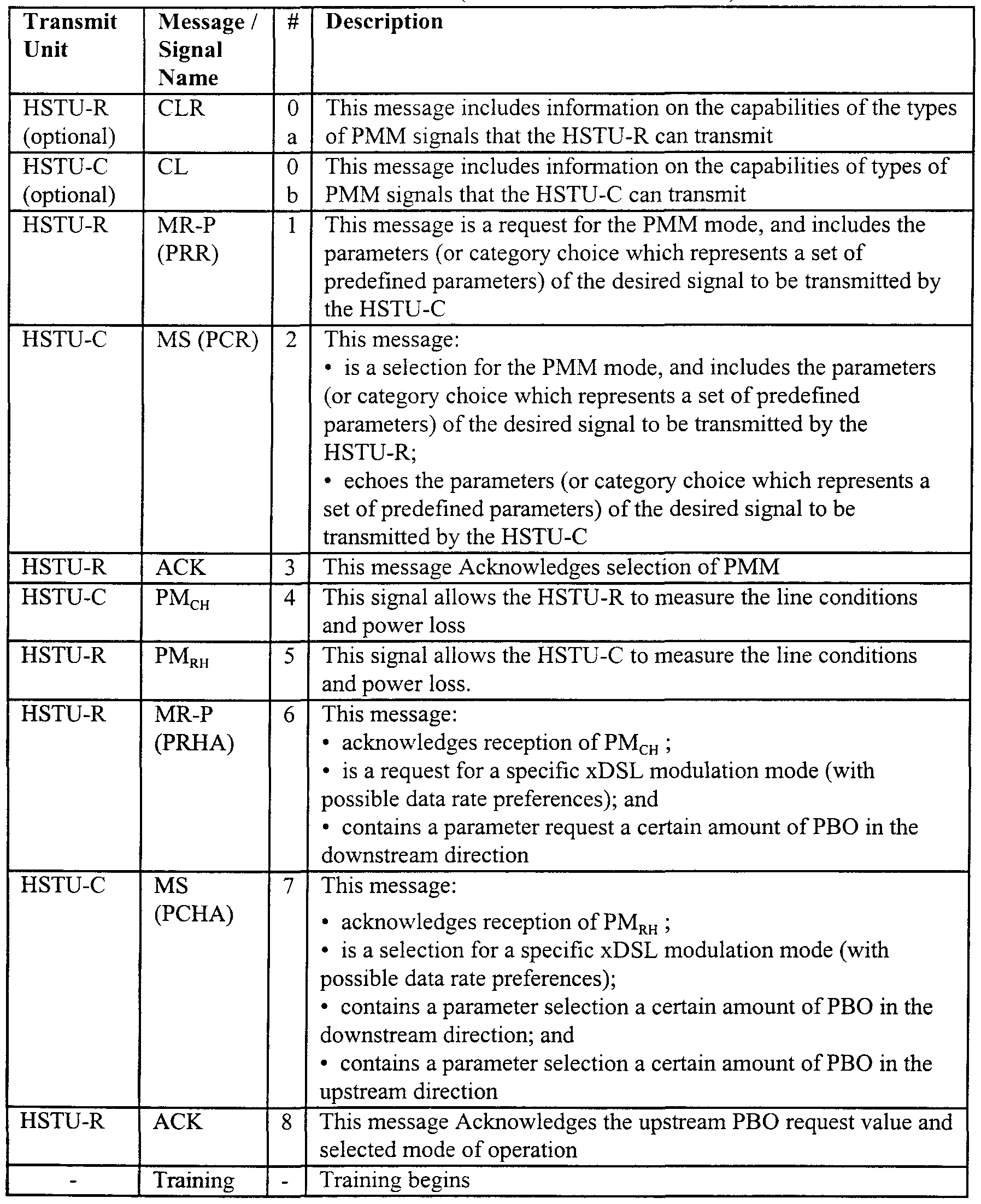
- the transactions and signal exchange is listed in Table 32, below, and illustrated in Fig. 5. It is assumed that the first message is always sent by the HSTU-R.
- the exchanged parameters are encoded in digital messages on the negotiation and control channels that are exchanged between the HSTU-R and HSTU-C.
- the HSTU-R makes power measurements based on the signals in PM CH .
- the minimum number of ca ⁇ iers is based upon the types of xDSL modems (e.g., ADSL, CDSL, HDSL, etc.) included in a communication loop.
- PM CH is composed from carriers in at least one of A43, B43, C43, A4, P4 or P43, and V128 or V138 carriers shown in Tables 33 through 36, below.
- PM CH can be composed from a type of specifiable broadband signal.
- the HSTU-C makes power measurements based on the signals in PM RH .
- the minimum number of carriers is based upon the types of xDSL modems included in the communication loop.
- PM RH is composed from carriers in at least one of A43, B43, C43, A4, P4 or P43 and V128 or V138 carriers shown in Tables 33 through 36.
- PM RH can be composed from a type of specifiable broadband signal.
- HSTU-R message modulation carriers can use any, some, or all of the carriers listed in the middle column of Tables 33 through 36.
- the HSTU-C message modulation carriers can use any, some, or all of carriers listed in the right column of Tables 33 through 36.
- MS messages are illustrated using an example xDSL refe ⁇ ed to as GDSL, but the invention can be applied to any xDSL.
- Octet coding of the MS messages are shown in Tables 37 through 42, below.
- the procedure with example contents is shown in Table 43, below.
- MS messages are explained using an example xDSL modem refe ⁇ ed to as GDSL, but the invention can be applied to any xDSL without departing from the spirit and/or scope of the invention.
- the octet coding of the MS messages is shown in Tables 44 through 49.
- This scheme is similar to the Fixed Measurement Signals With Standard Parameters, described above, except that the PM X signal is stepped from low power to high power.
- the transmission power is continuously stepped (increased) until the opposite HSTU-X can receive sufficient power and sends an "Acknowledgment".
- the stepping occurs in 2 dB increments, starting from approximately -90 dBm Hz every 200 ms; however, other stepping rates and timing values may be used without deviating from the spirit and/or scope of the invention.
- This scheme is similar to the Fixed Measurement Signals With Explicit Parameters, described above, except that the PM X signal is stepped (incrementally increased) from a low power to a high power. The power stepping continues until the opposite HSTU-X can receive sufficient power and sends an "Acknowledgment".
- the stepping occurs in approximate 2 dB increments, starting from approximately -90 dBm/Hz every 200 ms; however, other stepping rates and timing values may be used without deviating from the spirit and/or scope of the invention.
- the transaction sequence and signals are illustrated in Fig. 8.
- the transaction sequence and signals are the same as shown in Table 44, above, except that the PM X signal power varies over time.
- This sequence of signals and transaction which is refe ⁇ ed to as a power measurement modulation session (PMMS) is comprised of two types of elements: (1) digital negotiation and control channels; and (2) power measurement signals. Parameters that describe power measurement signals are negotiated and indicated as messages in the negotiation and control channels of the PMMS. After the power measurement signals are received and analyzed, the prefe ⁇ ed transmit levels are indicated in messages to the opposite side. It is noted that the procedures described herein are equally applicable to digital negotiation elements using either half duplex or full duplex procedures.
- the PMMS initially transmits (sends) power measurement signals at the lowest possible level.
- the PMM signals may optionally re-transmit the power measurement signals at incrementally higher power levels if the signals were not adequately received. Loop attenuation and minimum necessary transmit power is calculated by subtracting the measured receive power of the signals from the transmit power indicated in the messages of the PMMS. It is also understood that the power measurement signals may be initiated at any desired predetermined level without departing from the spirit and/or scope of the invention. Further, the functionality and methodology of using the PMMS can be applied to any handshake procedure, such as, but not limited to, ITU-T Recommendations V.8 and V.8bis.
- a new message, refe ⁇ ed to as MR-P is derived from the message MR that has parameters similar to message MS.
- Message MR-P is similar to message PRR, described above.
- MS also behaves the same as the PCR message, described above.
- Message MR-P (PRR) follows the same rules as message MR; however, message MR-
- the MR-P (PRR) parameters can be used to suggest values for parameters in the returning MS (PCR) message.
- PRR MR-P
- the MR-P message is assigned a revision number of at least 2.
- a device that supports MR-P can leave all of the other message types at revision level 1. It is noted that Section 9.3.2 of ITU Recommendation G.994.1 provides a procedure for message types having revision numbers greater than 1 (e.g., new message types).
- the xTU-C sends the first signals, and then, the xTU-R responds by sending signals. This allows the xTU-C to acknowledge the ITU-T Recommendation G.994.1 ACK message sent from the HSTU-R.
- the characteristics and timing of the PMM signals are predetermined in the ITU-T Recommendation G.994.1 transaction B exchange.
- the HSTU-X should make a rough estimate of the line length/attenuation by examining the received power levels of the ITU-T Recommendation G.994.1 ca ⁇ iers. In general, for reasons of spectral politeness, power levels should be selected so as to en on the side of using less power.
- the HSTU-C may: (a) Respond with REQ-MR-P (that is, create another new message type that is similar to REQ-MR; the HSTU-C can request to send MR, but it also has parameters like MR-P). However, the HSTU-C would not know that a PMM is being requested, unless the REQ-MR-P also contained parameters, since requesting MR-P is not necessarily limited to PMM;
- the HSTU-C may:
- the prefe ⁇ ed (but not sole) solution is to respond with REQ-MR, and then proceed as described above.
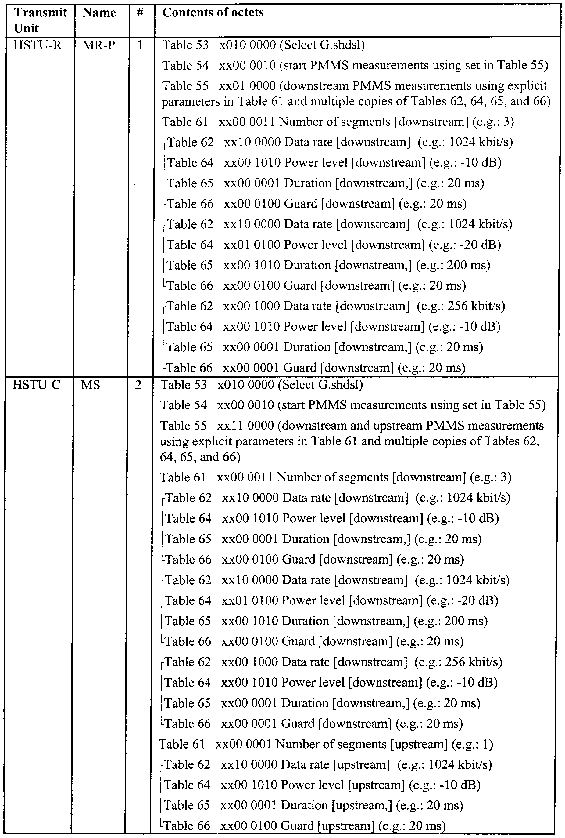
- the octet coding of the MR-P/MS messages is shown in Tables 53 through 55.
- the octet coding of the MR-P/MS messages is shown in Tables 56 through 59.
- a procedure with example contents is shown m Table 60, and is illustrated in Fig. 9.
- N ote - only one (1) value (ie, Mode) can be selectee
- G.SHDSL PMMS set #1 (1024 kbit/s; nominal X X X X X X X 1 power; 50 ms; 5 ms)
- G.SHDSL PMMS set #2 (256 kbit/s; nominal X X X X X X 1 X power; 50 ms; 5 ms)
- G.SHDSL PMMS set #3 (1024 kbit/s; -30 dB X X X X X 1 X X power; 50 ms; 5 ms)
- G.SHDSL PMMS set #4 (1024 kbit/s; -60 dB X X X X 1 X X X power; 50 ms; 5 ms)
- G.SHDSL PMMS set #4 (1024 kbit/s; -60 dB X X X 1 X X X X power; 500 ms; 50 ms)
- PMM signals are used in the activation of G.shdsl.
- 2-PAM see Section 6.2.1 of the above-mentioned G.shdsl Draft
- Example encodings of G.shdsl activation data rates are proposed below.
- Table 62 illustrates how to encoded the minimum requirements of 192 kbit/sec to 2304 kbit/s with a resolution of 64 kbit/s. It is noted that G.shdsl is designed such that slightly asymmetric upstream and downstream rates may be employed.
- the PM RH and PM CH signals may contain multiple signal segments. For example, several data rates for a given power level, or several power levels for a given data, may be sent to measure the PBO values. Thus, each segment is described with a "4-tuple" that comprises:
- Guard time e.g., amount of silence after the signal before the next signal will be sent.
- the session summary for this embodiment is similar to that described above with respect to the other embodiments.
- the xTU-R sends the first signals and then, the xTU-C sends signals. This allows the xTU-R to acknowledge the signal sent from the xTU-C with a second ITU-T Recommendation G.994.1 MR-P message sent from the HSTU-R. It is noted that the characteristics and timing of the PMM signals are predetermined in the transaction B exchange.
- Segmenting the MR message was not necessary since it could not contain any parameters and was always of short length. Thus, the segment acknowledge command " ACK(2)" must be allowed.
- the message NAK-NS may be a response to an MR-P to say the message — type — is not supported.
- NAK-NS cannot mean the requested parameters are not supported, since they can be overridden by the MS message.
- NAK-EF and NAK-CD are allowed for any message.
- REQ-CLR is appropriate for MR-P as well as MR to indicate that a capabilities exchange should be performed before the mode request.
- REQ-MS REQ-MS
- ACK(l) is not an appropriate response. Since NAK-NR is not sent in response to a CLR, it also should not be sent in response to an MR-P. Similarly, sending Request MR in response to a "REQ- MR" message would be a meaningless response to an MR or MR-P message.
- the transmit band is divided into one or more bands, as shown in Fig. 13. Each band is delimited by a lower frequency (F LX ) and a higher frequency (F HX ). For each band, a template is chosen to shape the transmit spectrum within that band. Example transmit templates are shown in Figs. 14 through 17.
- Octet 03 - PBO G ⁇ l bits 6-1 x 1 dB X X X X X X X X X
- the present invention has been described with respect to the xDSL procedure defined in ITU-T Recommendation G.994.1, the present invention is not limited to being used with this procedure, but is equally applicable with other procedures, such as, for example, ITU-T Recommendations V.8 and V.8bis.
- the methods described herein comprise dedicated hardware implementations including, but not limited to, application specific integrated circuits, programmable logic a ⁇ ays and other hardware devices constructed to implement the methods described herein.
- the invention may be implemented in software (e.g., a software modem) that is executed by a computer.
- MIME peripheral control
- IrDA IrDA
- RS232C USB
- ISA ISA
- ExCA PCMCIA
- public telephone networks ISDN, ATM, xDSL
Abstract
Description


Claims
Priority Applications (3)
| Application Number | Priority Date | Filing Date | Title |
|---|---|---|---|
| EP00923632.4A EP1095464B1 (en) | 1999-05-05 | 2000-05-04 | ACTIVATION OF MULTIPLE xDSL MODEMS WITH POWER CONTROL MEASUREMENT |
| CA002336631A CA2336631C (en) | 1999-05-05 | 2000-05-04 | Activation of multiple xdsl modems with power control measurement |
| AU43723/00A AU4372300A (en) | 1999-05-05 | 2000-05-29 | Activation of multiple xdsl modems with power control measurement |
Applications Claiming Priority (12)
| Application Number | Priority Date | Filing Date | Title |
|---|---|---|---|
| US13270299P | 1999-05-05 | 1999-05-05 | |
| US60/132,702 | 1999-05-05 | ||
| US13633399P | 1999-05-26 | 1999-05-26 | |
| US60/136,333 | 1999-05-26 | ||
| US14614099P | 1999-07-30 | 1999-07-30 | |
| US60/146,140 | 1999-07-30 | ||
| US15958899P | 1999-10-18 | 1999-10-18 | |
| US60/159,588 | 1999-10-18 | ||
| US16215099P | 1999-10-29 | 1999-10-29 | |
| US60/162,150 | 1999-10-29 | ||
| US16862899P | 1999-12-03 | 1999-12-03 | |
| US60/168,628 | 1999-12-03 |
Publications (1)
| Publication Number | Publication Date |
|---|---|
| WO2000067385A1 true WO2000067385A1 (en) | 2000-11-09 |
Family
ID=27558160
Family Applications (1)
| Application Number | Title | Priority Date | Filing Date |
|---|---|---|---|
| PCT/US2000/040019 WO2000067385A1 (en) | 1999-05-05 | 2000-05-04 | ACTIVATION OF MULTIPLE xDSL MODEMS WITH POWER CONTROL MEASUREMENT |
Country Status (6)
| Country | Link |
|---|---|
| EP (1) | EP1095464B1 (en) |
| KR (1) | KR100467364B1 (en) |
| CN (1) | CN1204697C (en) |
| AU (1) | AU4372300A (en) |
| CA (1) | CA2336631C (en) |
| WO (1) | WO2000067385A1 (en) |
Cited By (9)
| Publication number | Priority date | Publication date | Assignee | Title |
|---|---|---|---|---|
| DE10112816A1 (en) * | 2001-03-16 | 2002-09-26 | Siemens Ag | Signal transmission method using transceivers has adaption parameters for useful signal transmission obtained from measurement of interference along transmission channel in off-line mode |
| WO2003041316A1 (en) | 2001-11-09 | 2003-05-15 | Adc Dsl Systems, Inc. | Concurrent transmission of traffic from multiple communication interfaces |
| US6611868B1 (en) | 1999-05-21 | 2003-08-26 | 3Com Corporation | Method and system for automatic link hang up |
| WO2003098862A1 (en) * | 2002-05-15 | 2003-11-27 | Wireless Lan Systems Oy | Method and arrangement for adjusting transmission power in a digital subscriber line |
| US6804262B1 (en) * | 2000-04-28 | 2004-10-12 | 3Com Corporation | Method and apparatus for channel determination through power measurements |
| EP1484854A2 (en) * | 2003-06-02 | 2004-12-08 | Pioneer Corporation | Negotiation of transmission speed for IEEE 1394 buses |
| EP1505817A2 (en) * | 2003-08-08 | 2005-02-09 | Matsushita Electric Industrial Co., Ltd. | ADSL modem apparatus and ADSL modem communication method |
| US7089580B1 (en) * | 2000-03-29 | 2006-08-08 | 3Com Corporation | Method for improved cable modem ranging in a data-over-cable system |
| EP1850498A1 (en) * | 2005-03-10 | 2007-10-31 | Huawei Technologies Co., Ltd. | Method and system for extending signal transmission distance in asymmetric digital subscriber line |
Families Citing this family (3)
| Publication number | Priority date | Publication date | Assignee | Title |
|---|---|---|---|---|
| KR100842982B1 (en) * | 2001-11-22 | 2008-07-01 | 주식회사 엘지이아이 | Method for controlling upstream power level in cable modem |
| CN101924965B (en) * | 2009-06-17 | 2015-06-03 | 中兴通讯股份有限公司 | Link establishing method and device for second generation very-high-bit-rate digital subscriber loop (VDSL2) |
| CN103814552B (en) * | 2012-09-20 | 2016-11-23 | 华为技术有限公司 | Information processing method, equipment and system |
Citations (3)
| Publication number | Priority date | Publication date | Assignee | Title |
|---|---|---|---|---|
| US5321722A (en) * | 1989-07-21 | 1994-06-14 | Fujitsu Limited | Multipoint connected communication system having function of retraining modems provided therein and method of retraining the modems |
| US5912921A (en) * | 1997-08-20 | 1999-06-15 | Intermec Ip Corp. | Concurrent multiple data rate communications in a wireless local area network |
| US6064693A (en) * | 1997-02-28 | 2000-05-16 | Data Race, Inc. | System and method for handling underrun of compressed speech frames due to unsynchronized receive and transmit clock rates |
Family Cites Families (7)
| Publication number | Priority date | Publication date | Assignee | Title |
|---|---|---|---|---|
| US6647058B1 (en) * | 1997-06-23 | 2003-11-11 | Paradyne Corporation | Performance customization system and process for optimizing XDSL performance |
| JP3436742B2 (en) * | 1997-10-10 | 2003-08-18 | アウェア, インコーポレイテッド | Splitterless multi-carrier modem |
| US6708041B1 (en) * | 1997-12-15 | 2004-03-16 | Telefonaktiebolaget Lm (Publ) | Base station transmit power control in a CDMA cellular telephone system |
| TW405321B (en) * | 1998-01-09 | 2000-09-11 | Matsushita Graphic Communic | Activation of multiple xDSL modems with channel probe |
| EP1341339A3 (en) * | 1998-04-01 | 2004-01-02 | Matsushita Graphic Communication Systems, Inc. | Activation of multiple xDSL modems with implicit channel probe |
| US6606341B1 (en) * | 1999-03-22 | 2003-08-12 | Golden Bridge Technology, Inc. | Common packet channel with firm handoff |
| AU766021B2 (en) * | 1999-07-07 | 2003-10-09 | Samsung Electronics Co., Ltd. | Channel assignment apparatus and method for common packet channel in a WCDMA mobile communication system |
-
2000
- 2000-05-04 WO PCT/US2000/040019 patent/WO2000067385A1/en active IP Right Grant
- 2000-05-04 CN CNB008007845A patent/CN1204697C/en not_active Expired - Lifetime
- 2000-05-04 CA CA002336631A patent/CA2336631C/en not_active Expired - Lifetime
- 2000-05-04 KR KR10-2001-7000106A patent/KR100467364B1/en active IP Right Grant
- 2000-05-04 EP EP00923632.4A patent/EP1095464B1/en not_active Expired - Lifetime
- 2000-05-29 AU AU43723/00A patent/AU4372300A/en not_active Abandoned
Patent Citations (3)
| Publication number | Priority date | Publication date | Assignee | Title |
|---|---|---|---|---|
| US5321722A (en) * | 1989-07-21 | 1994-06-14 | Fujitsu Limited | Multipoint connected communication system having function of retraining modems provided therein and method of retraining the modems |
| US6064693A (en) * | 1997-02-28 | 2000-05-16 | Data Race, Inc. | System and method for handling underrun of compressed speech frames due to unsynchronized receive and transmit clock rates |
| US5912921A (en) * | 1997-08-20 | 1999-06-15 | Intermec Ip Corp. | Concurrent multiple data rate communications in a wireless local area network |
Cited By (18)
| Publication number | Priority date | Publication date | Assignee | Title |
|---|---|---|---|---|
| US6611868B1 (en) | 1999-05-21 | 2003-08-26 | 3Com Corporation | Method and system for automatic link hang up |
| US7089580B1 (en) * | 2000-03-29 | 2006-08-08 | 3Com Corporation | Method for improved cable modem ranging in a data-over-cable system |
| US6804262B1 (en) * | 2000-04-28 | 2004-10-12 | 3Com Corporation | Method and apparatus for channel determination through power measurements |
| DE10112816B4 (en) * | 2001-03-16 | 2005-12-29 | Siemens Ag | Method for rapid passive calibration of transceivers on their transmission medium |
| DE10112816A1 (en) * | 2001-03-16 | 2002-09-26 | Siemens Ag | Signal transmission method using transceivers has adaption parameters for useful signal transmission obtained from measurement of interference along transmission channel in off-line mode |
| EP1454443A1 (en) * | 2001-11-09 | 2004-09-08 | ADC DSL Systems, Inc. | Concurrent transmission of traffic from multiple communication interfaces |
| WO2003041316A1 (en) | 2001-11-09 | 2003-05-15 | Adc Dsl Systems, Inc. | Concurrent transmission of traffic from multiple communication interfaces |
| EP1454443A4 (en) * | 2001-11-09 | 2008-01-16 | Adc Dsl Sys Inc | Concurrent transmission of traffic from multiple communication interfaces |
| US7526002B2 (en) | 2001-11-09 | 2009-04-28 | Adc Dsl Systems, Inc. | Concurrent transmission of traffic from multiple communication interfaces |
| WO2003098862A1 (en) * | 2002-05-15 | 2003-11-27 | Wireless Lan Systems Oy | Method and arrangement for adjusting transmission power in a digital subscriber line |
| EP1484854A2 (en) * | 2003-06-02 | 2004-12-08 | Pioneer Corporation | Negotiation of transmission speed for IEEE 1394 buses |
| EP1484854A3 (en) * | 2003-06-02 | 2006-02-08 | Pioneer Corporation | Negotiation of transmission speed for IEEE 1394 buses |
| US7701855B2 (en) | 2003-06-02 | 2010-04-20 | Pioneer Corporation | Communication device, communication system, communication method, communication program and recording medium storing the communication program |
| EP1505817A2 (en) * | 2003-08-08 | 2005-02-09 | Matsushita Electric Industrial Co., Ltd. | ADSL modem apparatus and ADSL modem communication method |
| EP1505817A3 (en) * | 2003-08-08 | 2006-04-19 | Matsushita Electric Industrial Co., Ltd. | ADSL modem apparatus and ADSL modem communication method |
| EP1850498A1 (en) * | 2005-03-10 | 2007-10-31 | Huawei Technologies Co., Ltd. | Method and system for extending signal transmission distance in asymmetric digital subscriber line |
| EP1850498A4 (en) * | 2005-03-10 | 2008-03-26 | Huawei Tech Co Ltd | Method and system for extending signal transmission distance in asymmetric digital subscriber line |
| US8385509B2 (en) | 2005-03-10 | 2013-02-26 | Huawei Technologies Co., Ltd. | Method and system for extending transmission distance of ADSL signal |
Also Published As
| Publication number | Publication date |
|---|---|
| EP1095464B1 (en) | 2013-10-16 |
| CA2336631C (en) | 2008-02-26 |
| KR100467364B1 (en) | 2005-01-24 |
| CN1204697C (en) | 2005-06-01 |
| EP1095464A4 (en) | 2006-06-07 |
| KR20010071738A (en) | 2001-07-31 |
| CA2336631A1 (en) | 2000-11-09 |
| CN1304583A (en) | 2001-07-18 |
| EP1095464A1 (en) | 2001-05-02 |
| AU4372300A (en) | 2000-11-17 |
Similar Documents
| Publication | Publication Date | Title |
|---|---|---|
| US6751254B1 (en) | Activation of multiple xDSL modems with power control measurement | |
| JP3488234B1 (en) | Communication device and data communication method | |
| US20050201294A1 (en) | Activation of multiple xDSL modems with half duplex and full duplex procedures | |
| US6694470B1 (en) | Retransmission procedure and apparatus for handshaking protocol | |
| US20030206580A1 (en) | Activation of multiple xDSL modems with implicit channel probe | |
| CA2338077C (en) | Retransmission procedure and apparatus for handshaking protocol | |
| EP1095464B1 (en) | ACTIVATION OF MULTIPLE xDSL MODEMS WITH POWER CONTROL MEASUREMENT | |
| US20020061059A1 (en) | Scheme for the initialization of ADSL modems | |
| EP1062761B1 (en) | ACTIVATION OF MULTIPLE xDSL MODEMS WITH HALF DUPLEX AND FULL DUPLEX PROCEDURES |
Legal Events
| Date | Code | Title | Description |
|---|---|---|---|
| WWE | Wipo information: entry into national phase |
Ref document number: 00800784.5 Country of ref document: CN |
|
| AK | Designated states |
Kind code of ref document: A1 Designated state(s): AE AG AL AM AT AU AZ BA BB BG BR BY CA CH CN CR CU CZ DE DK DM DZ EE ES FI GB GD GE GH GM HR HU ID IL IN IS JP KE KG KP KR KZ LC LK LR LS LT LU LV MA MD MG MK MN MW MX NO NZ PL PT RO RU SD SE SG SI SK SL TJ TM TR TT TZ UA UG US UZ VN YU ZA ZW |
|
| AL | Designated countries for regional patents |
Kind code of ref document: A1 Designated state(s): GH GM KE LS MW SD SL SZ TZ UG ZW AM AZ BY KG KZ MD RU TJ TM AT BE CH CY DE DK ES FI FR GB GR IE IT LU MC NL PT SE BF BJ CF CG CI CM GA GN GW ML MR NE SN TD TG |
|
| WWE | Wipo information: entry into national phase |
Ref document number: 2000923632 Country of ref document: EP |
|
| 121 | Ep: the epo has been informed by wipo that ep was designated in this application | ||
| ENP | Entry into the national phase |
Ref document number: 2336631 Country of ref document: CA |
|
| WWE | Wipo information: entry into national phase |
Ref document number: 1020017000106 Country of ref document: KR |
|
| WWP | Wipo information: published in national office |
Ref document number: 2000923632 Country of ref document: EP |
|
| WWP | Wipo information: published in national office |
Ref document number: 1020017000106 Country of ref document: KR |
|
| REG | Reference to national code |
Ref country code: DE Ref legal event code: 8642 |
|
| NENP | Non-entry into the national phase |
Ref country code: JP |
|
| WWG | Wipo information: grant in national office |
Ref document number: 1020017000106 Country of ref document: KR |