WO1997032733A1 - Near infrared fluorescent security thermal transfer printing and marking ribbons - Google Patents
Near infrared fluorescent security thermal transfer printing and marking ribbons Download PDFInfo
- Publication number
- WO1997032733A1 WO1997032733A1 PCT/US1997/003556 US9703556W WO9732733A1 WO 1997032733 A1 WO1997032733 A1 WO 1997032733A1 US 9703556 W US9703556 W US 9703556W WO 9732733 A1 WO9732733 A1 WO 9732733A1
- Authority
- WO
- WIPO (PCT)
- Prior art keywords
- alkylene
- alkyl
- thermal transfer
- arylene
- near infrared
- Prior art date
Links
Classifications
-
- B—PERFORMING OPERATIONS; TRANSPORTING
- B41—PRINTING; LINING MACHINES; TYPEWRITERS; STAMPS
- B41M—PRINTING, DUPLICATING, MARKING, OR COPYING PROCESSES; COLOUR PRINTING
- B41M5/00—Duplicating or marking methods; Sheet materials for use therein
- B41M5/26—Thermography ; Marking by high energetic means, e.g. laser otherwise than by burning, and characterised by the material used
- B41M5/40—Thermography ; Marking by high energetic means, e.g. laser otherwise than by burning, and characterised by the material used characterised by the base backcoat, intermediate, or covering layers, e.g. for thermal transfer dye-donor or dye-receiver sheets; Heat, radiation filtering or absorbing means or layers; combined with other image registration layers or compositions; Special originals for reproduction by thermography
- B41M5/46—Thermography ; Marking by high energetic means, e.g. laser otherwise than by burning, and characterised by the material used characterised by the base backcoat, intermediate, or covering layers, e.g. for thermal transfer dye-donor or dye-receiver sheets; Heat, radiation filtering or absorbing means or layers; combined with other image registration layers or compositions; Special originals for reproduction by thermography characterised by the light-to-heat converting means; characterised by the heat or radiation filtering or absorbing means or layers
- B41M5/465—Infra-red radiation-absorbing materials, e.g. dyes, metals, silicates, C black
-
- B—PERFORMING OPERATIONS; TRANSPORTING
- B41—PRINTING; LINING MACHINES; TYPEWRITERS; STAMPS
- B41M—PRINTING, DUPLICATING, MARKING, OR COPYING PROCESSES; COLOUR PRINTING
- B41M3/00—Printing processes to produce particular kinds of printed work, e.g. patterns
- B41M3/14—Security printing
-
- B—PERFORMING OPERATIONS; TRANSPORTING
- B41—PRINTING; LINING MACHINES; TYPEWRITERS; STAMPS
- B41M—PRINTING, DUPLICATING, MARKING, OR COPYING PROCESSES; COLOUR PRINTING
- B41M3/00—Printing processes to produce particular kinds of printed work, e.g. patterns
- B41M3/14—Security printing
- B41M3/144—Security printing using fluorescent, luminescent or iridescent effects
-
- B—PERFORMING OPERATIONS; TRANSPORTING
- B41—PRINTING; LINING MACHINES; TYPEWRITERS; STAMPS
- B41M—PRINTING, DUPLICATING, MARKING, OR COPYING PROCESSES; COLOUR PRINTING
- B41M5/00—Duplicating or marking methods; Sheet materials for use therein
- B41M5/26—Thermography ; Marking by high energetic means, e.g. laser otherwise than by burning, and characterised by the material used
- B41M5/382—Contact thermal transfer or sublimation processes
- B41M5/385—Contact thermal transfer or sublimation processes characterised by the transferable dyes or pigments
-
- G—PHYSICS
- G06—COMPUTING; CALCULATING OR COUNTING
- G06K—GRAPHICAL DATA READING; PRESENTATION OF DATA; RECORD CARRIERS; HANDLING RECORD CARRIERS
- G06K1/00—Methods or arrangements for marking the record carrier in digital fashion
- G06K1/12—Methods or arrangements for marking the record carrier in digital fashion otherwise than by punching
- G06K1/121—Methods or arrangements for marking the record carrier in digital fashion otherwise than by punching by printing code marks
-
- B—PERFORMING OPERATIONS; TRANSPORTING
- B41—PRINTING; LINING MACHINES; TYPEWRITERS; STAMPS
- B41M—PRINTING, DUPLICATING, MARKING, OR COPYING PROCESSES; COLOUR PRINTING
- B41M2205/00—Printing methods or features related to printing methods; Location or type of the layers
- B41M2205/06—Printing methods or features related to printing methods; Location or type of the layers relating to melt (thermal) mass transfer
Definitions
- This invention relates to thermal transfer printing media containing near-infrared fluorophores (NIRFS) which may be monomeric, copolymerized or admixed into a carrier polymer/polymer backbone which is incorporated into the wax/thermoplastic resin which forms the thermally meltable ink layer (or printing media layer) on the thermal transfer ribbon
- NIRS near-infrared fluorophores
- Thermal transfer p ⁇ nting media and the ribbons used for thermal transfer are well known m the art Generally the ⁇ bbon comprises at least three mam layers, a thermally meltable ink layer, a polymer film layer and a heat resistant polymer layer. The compositions of the various layers are described in JP A 3-79,683, (Ap ⁇ l 4, 1991). However, thermal transfer media or ribbons capable of p ⁇ nting invisible marks are not disclosed
- Thermal transfer ribbons incorporating visible fluorescent dyes or pigments are disclosed in U.S. Patent No.4,627,997, 4,657,697, 4,816,344, 5,089,350 and 5,552,231. Ribbons containing marking compositions, which are invisible to the human eye, are not disclosed.
- Thermal transfer ribbons incorporating invisible UV dyes or pigments and visible pigments are disclosed in U.S. Patent No. 5,516,590. However, thermal transfer ribbons incorporating invisible marking compound which are not visible to the unaided human eye, and particularly invisible near infrared fluorescent compounds are not disclosed.
- the present invention relates to thermal transfer ribbons comprising a ribbon backing element and at least one printing media layer comprising at least one near infrared fluorescent compound in a concentration which provides detectable fluorescence without imparting color to a mark made from said printing media layer
- the present invention further relates to preparation of p ⁇ nting and marking ribbons consisting of thm film elements with p ⁇ nlmg media adhered to one side thereof
- a method for applying a mark comprising at least one invisible near infrared fluorescent compound comprising the steps of providing a thermal transfer ribbon comprising a ribbon backing element having coated on one side at least one printing media layer comprising at least one invisible NIRF compound; and contacting the non-coated side of said ribbon backing element with a heating element so as to contact said printing media layer with a print receiving media under conditions sufficient to thermally transfer an image to said print receiving media.
- Also disclosed is a method for detecting a thermal transfer mark comprising at least one invisible NIRF compound wherein said method comprises the steps of exciting said at least one invisible NIRF compound having a peak absorbance with radiation focused within 10 nm of said peak absorbance; and detecting fluorescence emitted from said invisible NIRF compound.
- Figure 1 is a cross-sectional side view of a thermal transfer ribbon having a single printing media layer containing both visible and invisible NIRF marking compounds.
- Figure 2 is a cross-sectional side view of a thermal transfer ribbon comprising a single printing media layer containing at least one invisible NIRF marking compound.
- Figure 3 is a cross-sectional side view of a thermal transfer printing ribbon having a first media layer containing at least one visible marking compound, and a second media layer containing at least one invisible NIRF marking compound.
- Figure 4 is a cross-sectional side view of a thermal transfer printing ribbon having a first media layer containing at least one invisible NIRF marking compound which is applied to said ribbon in a predetermined configuration and a second media layer containing at least one visible marking compound.
- Figure 5 is a top view of the thermal transfer printing ribbon shown in Figure 4.
- Figure 6 is a top view of a thermally transferred bar code as printed on a print receiving medium using the ribbon shown in FIG. 1 or FIG.3 or FIG.4, as the bar code would visibly appear under broad spectrum light or black light.
- Figure 6A is a top view of a thermally transferred bar code printed on a print receiving medium using the ribbon shown in Fig 2 as the product identification bar code would appear under broad spectrum and/or black light.
- Figure 6B is a top view of the bar code Figure 6A as the bar code would appear when excited with an appropriate near infrared radiation source and imaged with a camera designed to display contrast images of the fluorescence.
- Figure 7 is a top view of a thermally transferred bar code as pnnted on a p ⁇ nt receiving medium using the ribbon shown in FIG. 4, as the bar code would appear when excited with an appropriate near infrared radiation source and imaged with a camera designed to display contrast images of the fluorescence .
- Figure 8 is a cross-sectional side view of a thermal transfer ribbon having a first media layer containing at least one visible marking compound, a second media layer containing at least one invisible NIRF marking compound which is applied to said ⁇ bbon in a predetermined configuration and a third media layer containing at least one second invisible marking compound which is applied to said ribbon in a second predetermined configuration.
- Figure 9 is a top view of the ⁇ bbon shown m FIG 8
- Figure 10 is a top view of a bar code as pnnted on a p ⁇ nt receiving medium using the ribbon of FIG. 8, as the bar code would appear under broad spectrum or black light
- Figure 11 is a top view of the bar code shown in Figure 10 as it would appear when excited with an appropriate near infrared radiation source and imaged with a camera designed to display contrast images of the fluorescence.
- Figure 12 is a diagram of the components of an apparatus suitable for scanning and imaging the near infrared fluorescent marks of the present invention.
- the thermal transfer ribbons 10 of the present invention comprise at least three main layers: at least one thermally meltable ink or p ⁇ nting media layer 12 containing at least one NIRF compound which is adherent to one side of a polymer film layer or ribbon backing element 14 and a heat resistant polymer layer.
- Ribbon backing element 14 is preferably a long narrow strip of a flexible polymeric material.
- the ribbon backing should be compatible with p ⁇ nting media layer 12, have sufficient tensile strength to resist teanng and be sufficiently flexible to be wound around a spool or reel.
- Suitable backing mate ⁇ als include tissue paper, PET, PEN, a copolymer or blend of PET and/or PEN and Mylar.
- said backing mate ⁇ al is Mylar, such as that available from E. I. Dupont de Nemours and Co., Inc. m Wilmington, Del
- the p ⁇ nting media 12 of the present invention comp ⁇ ses a binding substrate and al least one marking compound selected from visible marking compounds such as pigments and dyes 16 and invisible NIRF marking compounds such as compolyme ⁇ zed NIRF compounds and monomeric NIRF compounds 18.
- marking compound as used herein includes both visible pigments and dyes as well as compolymerized and monomeric NIRF compounds, which are invisible to the human eye.
- Thermal transfer ribbons according to the present invention may include more than one printing media layer, however, at least one p ⁇ nting media layer must include at least one invisible NIRF compound either alone or in combination with other invisible NIRF compounds or visible marking compounds.
- Preferably said p ⁇ nting media is a uniform dispersion.
- Binding substrate 20 retains the uniform dispersion of marking compounds 16 and 18 against the ribbon-backing element 14 prior to the p ⁇ nting operation. In addition, binding substrate 20 retains the uniform dispersion of marking compounds 16 and 18 once printing media layer 12 is transferred onto p ⁇ nt receiving medium.
- Suitable binding substrates contain camuba wax, paraffin wax, candelilla wax, palm wax, beeswax and other natural waxes or oils such as ⁇ ce bran wax, gum arable, wax compatible resms and chemicals such as poly( ⁇ -methyl styrene), epoxy resins, acrylic resins, polyethylene oxide, polytetrafluoroethylene wax, polyurethanes, polyethylene waxes, methyl methacrylate resins, styrene-ethylene-butylene block copolymers, ethylene vinyl acetate, ethylene methyl acrylate copolymers, styrene butadiene elastomers, polyketones, amorphous polyester resins, cellulose esters, polyvinyl alcohol, solid fatty acids, amides and alcohols such as -octadecanol, sebacic acid, stearamide, behenyl alcohol, stearyl stearamide, casein, high density polyethylene emulsion,
- Visible marking compounds allow the printed image to appear visibly black or colored, as desired, under broad spectrum light.
- Visible marking compounds include visible pigments, dyes and other colorants which are known in the art and which can be suitably dispersed in the printing media. Examples of suitable visible marking compounds
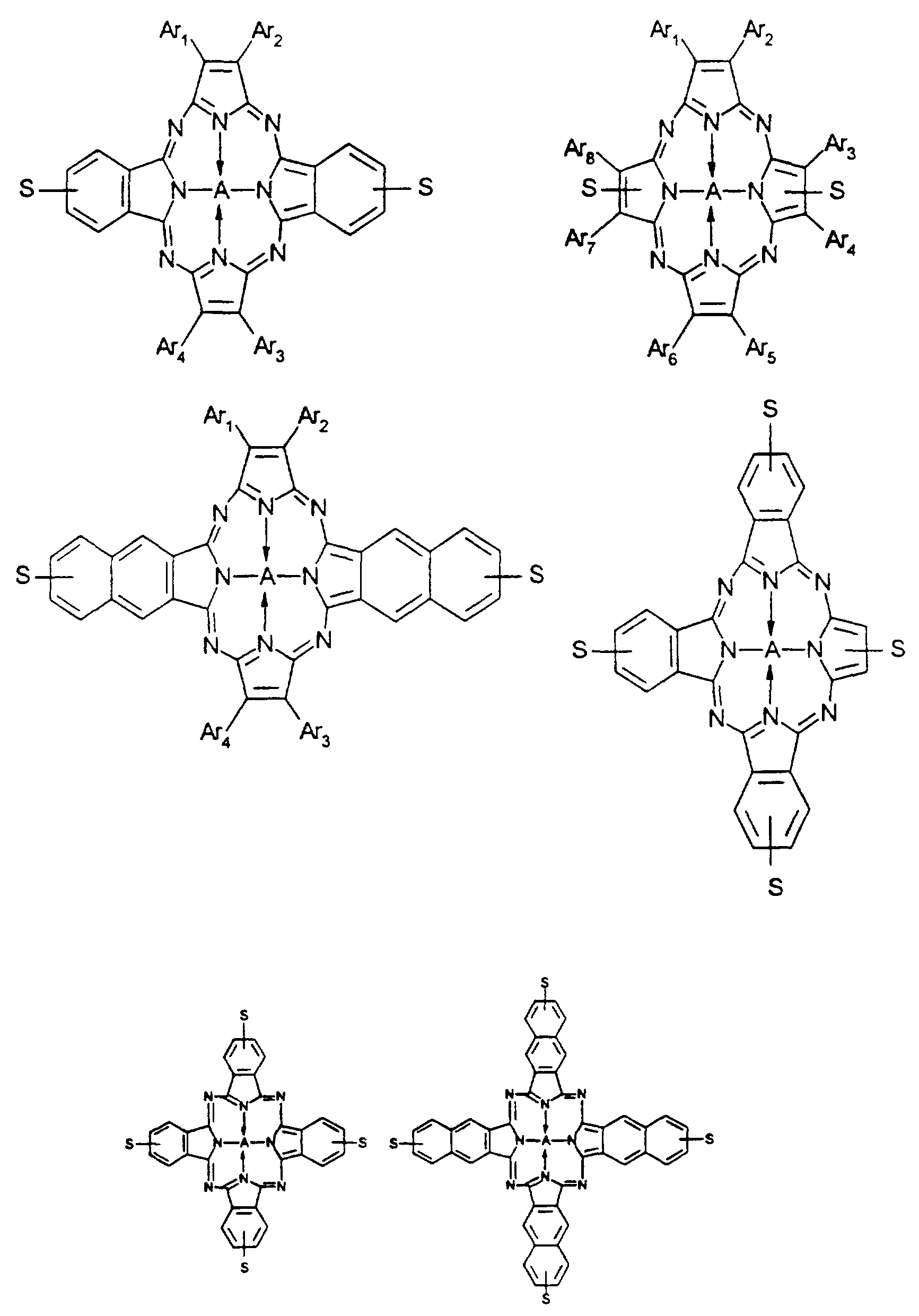
- Invisible NIRF marking compounds are black light but produce fluorescence or fiuoresce infrared light frequencies. Suitable invisible mar copoiymenzed near infrared fluorescent compounds or NIRFs
- each X may be the same or different and is selected from nitrogen and carbon substituted with Y, wherein Y is selected from hydrogen, C C ⁇ 2 alkyl, substituted C C ⁇ 2 alkyl, C 3 -C 8 cycloalkyl, aryl and heteroaryl, m is 1 through 9; R, - R « are the same or different and are selected from hydrogen, Cj-Cu alkyl, substituted C
- S represents 1-8 substituents bearing polymer forming reactive groups (capable of producing a polymer) which may be substituted into Y or the R
- -R « groups and Y any nuclear position can be used which produces the desired light absorption and fluorescence properties.
- the scope of the R ⁇ -R « includes symmetric and less symmetric combination of ⁇ ng systems designed to increase the abso ⁇ tion wavelengths. By designing the NIRFs with higher abso ⁇ tion wavelengths the color of the resultant compound is minimized
- X is 0, 2 or 4 nitrogens, more preferably 2 (diazapo ⁇ hines) or 4 nitrogens (tetra azapo ⁇ hines) and most preferably 4 nitrogens.
- suitable tetra azapo ⁇ hines includes, but arc not limited to:
- each Ar, Ar Arg group is independently selected from fused aryl ⁇ ng systems having one to four aryl rings fused therein and preferably from 1 to three ⁇ ngs.
- the Ar, Ar*- Ar* groups are oriented symmetrically about the pvrrole nuclei. For example.
- Ar ⁇ -Ari groups may alternating in structures where m is more than 3. If be disposed in any configuration, which provides th
- Ar'-Ar* groups have the same number of fused aryl rings therein.
- all Ar, A ⁇ '-AI groups in a NIRF are the same.
- a in the above general structure represents Al and Si bonded to halogen or oxygen or sulfur or nitrogen.
- Other suitable NIRFs are disclosed in U.S. 5,397,819 and 5,416,136, which are incorporated herein by reference.
- S is or contains the polymer forming reactive group, which provides the NIRF with its copolyme ⁇ zability or reactivity to the polymer backbone.
- Suitable reactive groups vary depending upon the backbone polymer, which is selected. Examples of such (S) groups include, but are not limited to:
- Oarylene CH ⁇ i,, 0-0,-0, 2 alkylene arylene-CH ⁇ H.,, O-CH2CH 0H2,
- Z is selected from O, NH, N-C C
- substituted C,-C l2 alkyl ⁇ s used to describe C ⁇ - 2 alkyl substituted with at least one group selected from C C ]2 alkoxy, halogen, trifluoromethyl, cyano, C 3 -C B cycloalkyl, aryl, aryloxy, arylthio, arylsulfonyl, heteroaryl, NHCOC C ⁇ 2 alkyl, NHS0 2 C,- C I2 alkyl, NHCO aryl, NH SO 2 aryl, NHCONH C,-C, 2 alkyl, NHCONH aryl, carbamoyl, sulfamoyl, S0 2 F, CONH C,-C, 2 alkyl, -S heteroaryl, CONH aryl, S0 2 NH C,-C] 2 alkyl, SO 2 N(C,-C 12 alkyl) 2 , S0 2 NH aryl, CONH C 3
- C C ⁇ 2 alkylene is used to describe straight or branched chain divalent saturated hydrocarbon radicals and these substituted with one or more groups selected from halogen, C,-C ⁇ 2 alkoxy, C 3 -C 3 cycloalkyl and aryl.
- aryl is used to desc ⁇ be phenyl and naphthyl radicals and these optionally substituted with halogen, C C 12 alkoxy, C,-C
- heteroaryl is used to represent mono or bicychc heteroaromatic radicals containing at least one "hetero" atom selected from oxygen, sulfur and nitrogen or a combination of these.
- suitable heteroaryl groups include: thiazolyl, benzothiazolyl, pyrazoyl, pyrrolyl, thienyl, furyl, thiadiazolyl, oxadiazolyl, benzoxazolyl, benzimidazolyl, pyridyl, pyrimidmyl, and t ⁇ azolyl and these radicals substituted with one or more of the substituents mentioned above for the term "aryl”.
- halogen is used to include fluorine, chlo ⁇ ne, bromine and iodine.
- polymer forming reactive group is used to describe a va ⁇ ety of reactive groups useful in making polymers and which are well-known m the art A va ⁇ ety of these groups are disclosed by the examples of substituents (S) desc ⁇ bed above
- NIRFs and methods for their preparation are known in the art and desc ⁇ bed m U.S Patents 4,255,273. 5,292,855, 5,336,714, 5,397,819, 5,461 ,136; 5,525,516; 5,553,714 and 5,423,432, which are inco ⁇ orated herein by reference.
- the NIRF compounds may be admixed in the binder substrate as monomers or admixed or copolymerized into the thermoplastic resins, which are admixed into the binder substrate.
- the NIRFs could be admixed or copolymerized into a second copolymer, which could be admixed in the binder substrate or copolymerized in the thermoplastic resin.
- the NIRFs are admixed or compolymenzed in the thermoplastic resins.
- the polymer backbone is any backbone, which is soluble, dispersible or emulsifiable in the binder substrate, or thermoplastic resins which are used as the main vehicle in the printing media.
- Suitable polymer backbones include polyesters, polyurethanes, polyolefins, polyamides, polysulfonamides, polyammes, polysiloxanes, polyacrylates, polyvinylacetates, polymethacrylates, polystyrenes, polysulfides and mixtures thereof.
- polyester backbones include, but are not limited to polyester NIRF compositions prepared from sebacid acid or dodecanedioicacid, diethylene glycol or poly(ethylene) glycols and copolymerizable NIRF dyes as described in US 5,397,819 and 5,461,136, which is inco ⁇ orated herein by reference.
- the reactive group S is selected to be readily polymerizable to prepare a selected backbone structure via appropriate techniques of homopolymerization or copolymerization.
- polyester backbones polyester reactive groups such as alkyl-OH, alkyl-C0 2 -alkyl, alkyl-C0 2 H, alkyl-C0 2 -aryl, aryl-CO 2 H, aryl-C0 2 -alkyl, and the like would generally be selected.
- Copolymerization yields copolymerized NIRFs similar to the compounds described in US Patents 5,292,855; 5,336,714 and 5,423,432, which are each, incorporated herein by reference.
- polyester/thermally stable near infrared fluorophoric compounds include squaraine, phthalocya ⁇ ine and naphthalocycanine type compounds, however other po ⁇ hine type compounds as described above are also suitable.
- the copolymerizable compounds of the present invention can be readily formulated into invisible thermally meltable inks which are suitable for thermal transfer. Generally only small amounts of the NIRFs of the present invention are required to achieve the desired result. Amounts between about 10 ppm and 1000 ppm are sufficient.
- the thermal transfer ⁇ bbon of the present invention is produced in a rv.o stage process wherein the first stage includes preparation of a specific wax emulsion or formulation and the second stage includes preparation of the transfer coating or layer.
- a wax adhesive emulsion uses hydrocarbons, paraffin or ozoke ⁇ te, camauba, microcrystalhne waxes and an ethylene vinyl acetate copolymer and/or a hydrocarbon resin soluble in aliphatic solvents.
- the wax emulsion uses waxes plus the acetate copolymer plus the hydrocarbon resin in one formulation. In another formulation the wax emulsion uses waxes plus the acetate copolymer of the hydrocarbon resin.
- One embodiment of the present invention compnses a dispersion of an acetate copolymer, at least one acrylic resin, carbon black and at least one invisible NIRF compound. Suitable examples of the components and their amounts are well known in the art.
- the resulting dispersion was coated at 20-25°C onto the ⁇ bbon backing element 14 at a dry coat weight of 3 +/- 0.5 grams per square meter to form finished NIRF thermal transfer p ⁇ nting ribbon 10.
- NIRF thermal transfer and p ⁇ nting ⁇ bbon 30 compnsing a single p ⁇ nting media layer 32 which is adhered to one side of the ⁇ bbon backing element 34.
- P ⁇ nting media layer 32 compnses a uniform dispersion of monome ⁇ c or polymeric NIRF dye compositions 38 in binding substrate 40 without any visible marking compounds.
- NIRF compositions are inactive under broad spectrum light and black light
- images printed using ribbon 30 are rransparem or invisible under broad spectrum light and black light, but the fluorescence generated when activated with appropriate near infrared light frequencies can be detected using a suitable detector or imaging device.
- the transfer image could be detected or decoded with a near infrared fluorescence bar code scanner. Moreover, a strong image could be discerned as depicted on FIG. 6B when the transfer image was imaged with a near infrared fluorescence camera designed for display of contrast images of the near infrared fluorescence.
- the thermal transfer also left a negative image of the bar code on the ⁇ bbon 30, which is invisible under broad spectrum light or black light, but can be examined with a near infrared fluorescence camera which permits display of a contrast image on a video monitor as depicted on FIG. 6.
- Another embodiment of the present invention comprises an emulsion of mineral spirits, copolymer resin, thermoplastic resm, wax and at least one invisible NIRF compound. Suitable examples of the components and their amounts are well known in the art.
- ⁇ bbon backing element 34 The emulsion is coated onto ⁇ bbon backing element 34 at a dry coat weight of about 3 grams per square meter to form ⁇ bbon 30 which performed well when used to transfer images to paper as desc ⁇ bed above.
- a fourth preferred formulation for the NIRF thermal transfer p ⁇ nting ana marking ribbon of the present invention is given below.
- FIG.3 a third preferred embodiment of a NIRF thermal transfer
- media layer 52 preferably includes a uniform dispersion of a monome ⁇ c or polymeric NIRF dye composition in binding substrate 60
- Second p ⁇ nting media layer 62 preferabl includes a uniform dispersion of visible black or colored pigments 56 in binding substrate 64.
- images pnnted using ribbon 50 compnse a bottom layer of second p ⁇ nting media layer 62 with a uniform dispersion of black or colored pigments 56 in binding substrate 64
- compositions 58 are transparent, and thus invisible under broad spectrum light and black light, visible black cr colored pigments 56 allow the pnnted images to appear visibly black or colored, as desired, under broad s ectrum li ht or black light. However, compositions 58 generate
- FIG. 4 and 5 a fourth preferred embodiment of a NIRF thermal transfer r ⁇ nting and marking ribbon in accordance with the present invention, generally indicated by reference numeral 70, is shown.
- Ribbon 70 consists of first spot coated p ⁇ nting media layer 72 which is adhered to one side of ribbon backing element 74, and second p ⁇ nting media layer 82 which is
- first spot coated printing media layer 72 adhered to the surface of first spot coated printing media layer 72 distal from backing element 74 and to portions of backing element 74 not covered by first spot coated printing media layer 72.
- first spot coated p ⁇ nting media layer 72 could be spot coated a pattern or configuration identifying a particular store's name, logo or some other desired identifiable configuration. as represented by repeating pattern 86 of ABC's shown in FIG. 5.
- Second p ⁇ nting media layer 82 preferably includes a uniform dispersion of visible black or colored pigments 76 5 in binding substrate 84. Images pnnted using ribbon 70 consist of a bottom layer of second printing media layer 82 with a uniform dispersion of visible black or colored pigments 76 in binding substrate 84 and a top layer of first spot coated printing media layer 72 with the spot coated pattern or configuration of uniform dispersion of NIRF dye composition 78 in binding substrate 80. Since composition 78 is transparent, and thus invisible under broad 10 spectrum light, visible black or colored pigments 76 allow the printed images to appear visibly black or colored, as desired, under broad spectrum light or black light as shown in
- NIRF dye composition 78 present m repeating pattern 86 generate near infrared
- Binding substrate 80 retains the spot coated uniform dispersion of NIRF dye composition 78 against backing element 74 prior to the p ⁇ nting operation. Similarly, binding substrate 84 retains the uniform dispersion of visible black or colored pigments 76
- binding substrate 80 retains the spot coated uniform dispersion of NIRF dye composition 78 and binding substrate 84 retains the uniform dispersion of visible black or colored pigments 76 after second pnnting media layer 82 and first spot coated printing media layer 72 are transferred onto paper or some other pnnting medium.
- Ribbon 90 consists of first spot coated printing media layer 92 which is adhered to one side of ribbon backing element 94, second spot coated printing media layer 102 which is adhered to the same side of ribbon
- backing element 94 and third printing media layer 108 which is adhered to the surfaces of first spot coated printing media layer 92 and second spot coated printing media 102 distal from backing element 94 and to portions of backing element 94 not covered by first spot coated pnnting media layer 92 and second spot coated p ⁇ nting media layer 102.
- First spot coated p ⁇ nting media layer 92 preferably includes a uniform dispersion
- second spot coated p ⁇ nting media layer 102 preferably includes a uniform dispersion of monome ⁇ c or polyme ⁇ c NIRF dye composition 110 m binding substrate 104 spot coated in any desired pattern or configuration on ⁇ bbon backing element 94
- first spot coated p ⁇ nting media layer 92 could be spot coated in a first patiem or configuration represented by repeating pattern of ABC's shown in FIG.
- second spot coated printing media layer 102 could be spot coated in a second pattern or configuration as represented by repeating pattern 112 of XYZ's shown in FIG. 9, identifying, for example, a particular product logo or trademark. If desired, second spot coated printing media layer 102 could be allowed to overlap first spot coated printing media layer 92 in a predetermined manner.
- Third printing media layer 108 preferably includes a uniform dispersion of visible black or colored pigments 96 binding substrate 114.
- Images printed using ribbon 90 consist of a bottom layer of third pnnting media layer 108 with a uniform dispersion of visible black or colored pigments 96 in binding substrate 114 and a top layer of first spot coated p ⁇ nting media layer 92 with the spot coated pattern or configuration of uniform dispersion of monome ⁇ c or polyme ⁇ c NIRF dye composition 98 binding substrate 100 and second spot coated p ⁇ nting media layer 102 with the spot coated pattern or configurations of uniform dispersion of monome ⁇ c or polyme ⁇ c NIRF dye composition 110 in binding substrate 104. Since 98 and 110 are transparent, and thus invisible under broad spectrum light and black light, visible black or colored pigments 96 allow the printed images to appear visibly black or colored, as desired, under broad spectrum light as shown in FIG.
- Monomeric or polymeric NIRF dye composition 98 present in repeating pattern 106 and monomeric or polymeric NIRF dye composition 110 present in repeating pattern 112 generate near infrared fluorescence when activated by appropriate near infrared light frequencies from lasers or LED sources, and this fluorescence can be detected by a suitable detector, scanner or imaging camera.
- the unique pattern created by the fluorescence and imaged by a near infrared fluorescence camera is shown in FIG. 11 for the case of monomeric or polymeric NIRF dye compositions 98 and 110 being identical. If 98 and 110 are selected to be non-identical, then either 98 or 110 can be detected using the camera configuration described in Example 2 and either repeating pattern 106 or 112 will be stored in the digital camera memory and can be observed on the video monitor.
- the camera jwerr are reconfigured to permit detection of fluorescence generated by excitation of the printed repeating pattern 106 or 112 in FIG. 9 which previously was not recorded, by excitation with approp ⁇ ate near infrared light from a laser correct for NIRF dye composition 98 or 110, then the other repeating pattern 106 or 112 will be selectively stored the digital camera memory and can be observed on the monitor Thus, by correct selection of laser excitation sources and filters on the camera desc ⁇ bed in Example 2, it is possible to visualize the image of either repeating pattern 106 or repeating pattern 112. If desired, both images so recorded can be displayed simultaneously as shown in FIG.
- Binding substrates 100 and 104 retain the spot coated uniform dispersions of monomeric or polymeric NIRF dye composition 98 and 110 in their layers prior to the printing operation and after the printing media is transferred to the pnnt receiving media.
- the print media layer of the present invention may also include additional components to achieve certain desired results.
- additional components may include, but are not limited to molecular weight modifiers, charge modifiers, plasticizer ⁇ and cross linking agents.
- the NIRF thermal transfer printing and marking ribbon of the present invention is superior to the ultraviolet fluorescent thermal transfer printing and marking ribbon previously disclosed in the prior art.
- UV fluorescent images or marks are easily activated, and visualized by human vision under black light, and even under many conventional room lighting conditions such as fluorescent bulbs. This makes it easy to locate such images or marks under a black light.
- the images and marks of the present invention are not easily identified by human vision under black light, broad spectrum light, or infrared light.
- the present invention provides a superior feature in security marking of ED documents and items of commerce to prevent fraudulent use, counterfeit, substitution, and diversion of consumer or industrial products.
- the images and marks of the present invention have superior light, thermal, and chemical stability and are more resistant to fluorescence quenching mechanisms commonly encountered in formulation of thermal transfer ribbons. Moreover, the NIRF dyes can be used at lower concentrations due to greater overall absorbance and fluorescence quantum efficiencies.
- the images could be detected by a simple "yes/no" detector , which detects the presence, but not the configuration of the mark or image.
- the images or marks may be detected using a scanner which can detect and distinguish unique images such as barcodes or a near infrared fluorescence camera designed for display of contrast images of the fluorescence on a video monitor.
- a suitable method compnses the steps of providing a thermal transfer ⁇ bbon compnsmg a ⁇ bbon backing element and at least one printing media layer compnsmg at least one invisible NIRF compound, and contacting said nbbon backing element with a heating element so as to contact said pnnting media layer with a pnnt receiving media under conditions sufficient to thermally transfer an image thereto
- Also disclosed in the present invention is a method compnsmg the steps of excitmg a thermal transfer image containing at least one invisible NIRF compound with radiation having a wavelength between about 630 nm and 1 lOOnm; and detecting fluorescence emitted from said invisible NIRF compound.
- Suitable NIRF cameras are designed to detect and display contrast images of the fluorescence on a video monitor for human visualization and/or inspection, as shown m Figure 7.
- An example of suitable instrumentation for higher power laser scanning for a digital camera is described as follows:
- the excitation source is a 780 nm (50 mW) laser diode such as those available from Lasermax Inc., Rochester, New York coupled with a scanning system.
- the scanner system comprises a real-time galvanometer-based point scanning system with near uniform illumination.
- Scanning head and the control boards are powered by a t ⁇ ple DC power supply (VIZ model WP 708A, General Scanning Inc., Watertown, Massachusetts)
- the x- y scan head compnses of a 8 kHz counter-rotating scanner and a moving magnet galvanometer
- the galvanometer provided the ve ⁇ ical scan
- the counter-rotating scanner provided the ho ⁇ zontal scan
- Three control boards were supplied with the scan head the pixel clock, counter-rotating scanner dm er and a moving magnet gahanometer servo-controller
- the sinusoidal motion of the counter-rotating scanner was corrected by phase locking the pixel clock to the scanner and by adjusting the clock rate to match the sinusoidal velocity
- the scanning system had a frame rate of up to 100 frames per second
- the detection system comp ⁇ sed a CCD camera (model HPC-2 large area CCD Imaging System, Spectra source Instruments, California), thermoelect ⁇ cally cooled by a cooling umt and controlled by an IBM PC with an interface card A 55 mm Nikon lens with a 2 4 f stop was used for collecting the emitted light
- two emission bandpass filters (2", rejection ratio of 10 5 ) with a cutoff of 820 ⁇ 20 nm and 820 ⁇ 10 nm were used
- the thermal transfer ⁇ bbon of the present invention wherein said pnnting media layer further compnses a visible marking compound
- the thermal transfer nbbon of the present invention further compnsmg a second pnnting media layer wherein first p ⁇ nting media layer compnses at least one visible marking compound and/or at least one second near infrared fluorescent compound and said second p ⁇ nting media layer compnses said at least one near infrared fluorescent compound
- the thermal transfer ⁇ bbon of the present invention further comp ⁇ smg a second pnnting media layer compnsmg at least one visible marking compound and/or at least one second near infrared fluorescent compound
- the thermal transfer nbbon of the present invention wherein said first p ⁇ nting media layer is coated on said ⁇ bbon backing element in a specific configuration
- the thermal transfer ⁇ bbon of the present invention wherein said first p ⁇ nting media layer is coated on said ribbon backing element in a specific configuration
- the thermal transfer nbbon of the present invention wherein said ⁇ bbon compnses at least three p ⁇ nt media layers se ⁇ ally coated on said nbbon backing element
- the thermal transfer ⁇ bbon of the present invention wherein at least one pnnt media layer compnses at least one visible marking compound
- thermal transfer ⁇ bbon of the present invention wherein at least one pnnting media layer is coated on in a specific configuration
- thermo transfer nbbon of the present invention wherein said p ⁇ nting media layer compnses a dispersion of an acetate copolymer, at least one acrylic resm and said at least one invisible NIRF compound
- thermal transfer nbbon of the present invention wherein said pnnting media layer further compnses from about 5% to about 15% carbon black dispersed therein
- thermal transfer nbbon of the present invention wherein said pnnting media layer further compnses at least one visible marking compound dispersed therein
- thermal-transfer ⁇ bbon of the present invention wherein two or four of the X substituents are N
- polyester backbones include, but are not limited to polyester NIRF compositions prepared from sebacid acid or dodecanedioicacid, diethylene ghcol or poly(ethvlene) glycols and
- thermoplastic resin thermoplastic resin
- wax thermoplastic resin
- the nbbon of the present invention wherein said prmtmg media layer compnses a solution of (C6H 5 0) 4 PcA10C6H 3 -3,5-d ⁇ -CO ⁇ 8 CH 3 7-n in camauba wax and stearyl alcohol
- said coating layer compnses about 15 to about 30% of aqueous polymer composition compnsmg poly(ethylene oxide) resm, casein, high density polyethylene, camauba wax and from about 5 to about 15% of at least one water dissipatible polymer emulsion compnsmg at least one sulfomonomer and at least one near infrared fluorescent compound copolymerized therein
- said thermal transfer ⁇ bbon of the present invention wherein said aqueous polymer composition is present in an amount between about 20 and about
- said water dissipatible polymer emulsion is present in an amount between about 5% and about 10%
- thermo transfer ⁇ bbon of the present invention wherein said po ⁇ hine is selected from the group consisting of
- each Ar is the same or different and is independently selected from the group consisting of fused aryl nng systems having one to four aryl rings fused therein
- thermo transfer nbbon of the present invention wherein said near infrared fluorescent compound is selected from phthalocyamne and naphthalocyanine of the formulae
- M is selected from the group consisting of Al O arylene (C0 2 alkyl) 2 andSi(Oarylene C0 2 ,alkyl) 2 wherein S is selected from the group consisting of H, alkyl.
- O alkyl, O arylene (C0 2 alkyl) and S arylene (C0 2 alkyl) n is 1 or 2, and said alkyl the same or different and is selected from C 4 -C ⁇ 8 straight or branched alkyl and wherein said phthalocyamne has at least two alkyl groups selected from the group consising of Cn-C straight or branched alkyls, and
- M is selected from the group consisting of Al O arylene (C0 2 alkyl) 2 and Si (O arylene C0 2 alkyl) 2
- S is selected from the group consisting of H, alkyl, O alkyl, O arylene (C0 2 alkyl), S arylene (C0 2 alkyl), NH arylene (C0 2 alkyl) and NH alkylene C0 2 alkyl
- n is 1-6; and said alkyl the same or different and is selected from G Cu straight or branched alkyl and wherein said naphthalocyanine has at least two alkyl groups selected from the group consising of C ⁇ 2 -C ⁇ s straight or branched alky Is.
- Patent 5,336,714 The flask and contents were immersed in a Belmont metal bath at 200°C with a nitrogen sweep over the reaction mixture and held for 1.0 hr The temperature was increased to 220°C, held for 2.0 hours, and then increased to 270°C over about 10 minutes Vacuum was then applied to lower the pressure to about 0.1 torr over about 30 minutes and the polycondensation reaction completed by heating at about 270°C for 30 minutes.
- the resulting polymer which contains about 1000 ppm of copolymerized near infrared fluorophore has an inherent viscosity of 0 49 as measured in a 60/40 ratio by weight of phenol/tetrachloroethane at a concentration of 0.5g per 100 mL.
- the polymer which was a very viscous liquid, has a weight average molecular weight (Mw) of 21,190, a number average molecular weight (Mn) of 8182, and a polydispersity (Mw ⁇ Mn) value of 2.68
- Mw weight average molecular weight
- Mn number average molecular weight
- Mw ⁇ Mn polydispersity
- a coating composition consisting of a mixture of 5g UCAR Latex emulsion 379 (Union Carbide) and 5 g Eastman aqueous NIRF polymer emulsion desc ⁇ bed in US Application Docket No 70278, Example 9 except using 0 2 g NIRF compound of Example 29 of US Patent 5,397,819 instead of 0 4 g was coated on white paper to give a thin uniform film approximately 1-2 mils thick after drying The dry coating had about 10 ppm of NIRF dye polymer The coating was marked with crossing line patterns using a black ink pen to give a contrast image (Test Paper 1) Using the thermal transfer pnnting nbbon of the present invention it is possible to transfer bar code patterns to white paper which are invisible (Test Paper 2) The Test Paper 1 was excited in a dark room with a 670 mn one milliwatt laser source by manual and rapid continuous scanmng of the laser beam over the crossing line patterns The scanning was continued while a modified Kodak digital camera system was permitted to record any
- the excitation source is a 780 nm (50 mW) laser diode such as those available from Rochester, New York coupled with a scanning system.
- the scanner system compnses a real-time galvanometer-based point scanning system with near uniform illumination Scanmng head and the control boards (General Scanning Inc., Watertown, Massachusetts) are powered by a triple DC power supply (VIZ model WP 708A, General Scanning Inc., Watertown, Massachusetts)
- the x-y scan head compnses a 8 kHz counter- rotating scanner and a moving magnet galvanometer.
- the galvanometer provided the vertical scan and the counter-rotating scanner provided the ho ⁇ zontal scan
- Three control boards were supplied with the scan head, the pixel clock, counter-rotating scanner dnver and a moving magnet galvanometer servo-controller.
- the sinusoidal motion of the counter-rotating scanner was corrected by phase locking the pixel clock to the scanner and by adjusting the clock rate to match the sinusoidal velocity
- the scanning system had a frame rate of up to 100 frames per second
- the detection system compnsed a CCD camera (model HPC-2 large area CCD
- Data acquisition and analysis were performed by Windows-based software supplied by Spectra source.
- the software also provided a script language programming to automate data acquisition and to control external devices within the application program
- the software had provisions for dark field and flat field corrections
- a 90 MHZ Pentium computer with 32 MB RAM was used to gather data and control the CCD camera
- a Marshall Electronics (Culver City, CA) Model V-1055 CCD camera (12V DC 100 ma, 0.005 lux 510-492 pixels, 3 ounces, 1 '/ ⁇ 'xl'/ ⁇ 'xl” with a Marshall Electronics V-4508,8 mm,f 1.3 lens was mounted inside the top surface of a 12" tall, 6" long and 3" wide plastic box, which was open at the bottom.
- a 3 mW, approximately 675 nm diode laser (Power Technology Inc., Little Rock, AR, Model PM03(670-5)) was mounted.
- the laser's lens was defocused to produce an illuminated area of approximately 1" x3" at the open bottom of the box
- an approximately lOmW, 780 nm Laser was mounted on the other side of die camera. This laser's lens was also defocused to illuminate an area of about 1" x 3" al the bottom of the box.
- the camera and lasers were connected to a battery pack holding eight AA batte ⁇ es All eight battenes in series were used to power the 780nm laser and the camera Only three of the batte ⁇ es were needed for the 675 nm laser
- the fluorescence from items marked with fluorophores requiring excitation near 780 nm or near 675 nm could be induced when the imaging device was placed onto such items.
- an appropriate filter was placed in front of the cameras lens using a plastic holder.
- bandpass filters centered at either 720 nm or 730 nm (Conon Holhston, MA, models 510-720-F or 510- 730-F, bandpass of 12 nm FWHM) or long-pass cut-on filters with a cut-on wavelength of 715 nm or 725 nm (Oriel Instruments, Stratford, CT, Catalog #51345 or 51315) were used.
- the cut-on filters are best used in pairs of two stacked back-to-back.
- band pass filters centered at 820 nm, 830 nm or 840 nm (Conon, 510-820-F, 510- 830-F or 510-840-F) or Schott Glass equivalent RG-830 or RG 850 Long pass, cut-on filters (Oriel Instruments, Catalog #51352 or 51360, also used in pairs) are placed m front of the camera The images can be viewed on a handheld 2.7" diagonal video monitor (Sony FM 030 watch CAM) that is connected to the camera. Alternatively for better image quality, the camera could be connected to any standard television monitor
- the model V-1055 (Marshall Electronics) with a V-4508 lens was mounted inside a plastic housing 7.5" tall x 3' " wide x 4" long
- the camera was mounted in such a way as to place the front of the lens 3 " above an 2 " ' x 1 V* " opening Four 5 mW, 780 nm
- Laser diodes without collimating lenses were placed 2" from the opening and spaced so as to relatively evenly illuminate any object placed under the opening in the box
- Each laser diode was powered by a laser diode driver.
- a 3" diagonal or active matrix color LCD monitor (Sony Model XV-M30) was mounted on a swivel to the top of the plastic housing. All power was supplied by a 12V lead-acid camcorder battery.
- Two RG-850 long-pass optical filters were used in front of the camera lens to reject the laser light, but pass the fluorescent light.
- the mixture was heated 1 min. at 202°C and then at 164 C C with stirring for 2 hours; during this time the dye gradually was converted to the stearyl ester derivative and methanol distilled into the Dean Stark trap (plus trace quantities of nBuOH).
- the product dispersed well into the wax solvent.
- the product was used directly in preparing NIRF thermal transfer printing and marking ribbon 30 shown in FIG. 2 as described above.
- Example No. 3 The procedure of Example No. 3 was repeated using .02 g NIRF dye (tert-butyl)4 NcA10C6H3-3,5-di-C02CH3 in place of component IV. At the end of the reaction the product (tert-butyl) NcAl OC6H 3 -3,5-di-C0 2 C ⁇ 8 H 37 . n dispersion in Camauba wax or Rice Bran Wax and stearyl alcohol was used directly is preparing thermal transfer printing and marking ribbon type 30 shown in FIG. 2 as described above.
- Example No. 6 The procedure of Example No. 3 was repeated using .02 g NIRF dye (tert-Butyl) 4 NcSi (OC6H 3 -4-C0 2 CH 3 ) in place of component IV. At the end of the reaction the product (tert Butyl)4 NcSi(OC6H3-4-C0 2 C ⁇ 8 H 3 7-n) dispersion in Camauba wax or Rice Bran Wax and stearyl alcohol was used directly in preparing thermal transfer printing and marking ribbon type 30 shown in FIG. 2 as described above.
- Example No. 6 The procedure of Example No. 3 was repeated using .02 g NIRF dye (tert-Butyl) 4 NcSi (OC6H 3 -4-C0 2 CH 3 ) in place of component IV. At the end of the reaction the product (tert Butyl)4 NcSi(OC6H3-4-C0 2 C ⁇ 8 H 3 7-n) dispersion in Camauba wax or Rice Bran Wax and stearyl
- Example No. 3 The procedure of Example No. 3 was repeated using .02 g NIRF dye (C ⁇ H 5 S) PcA10C6H 3 -3,5-di-C0 2 CH 3 in place of component IV. At the end of the reaction the product PcA10C 6 Hj-3,5-di-C ⁇ 2 C] 8 H 37 -n dispersion in Camauba wax or Rice Bran Wax and stearyl alcohol was used directly in preparing thermal transfer printing and marking ribbon type 30 shown in FIG. 2 as described above.
- the ⁇ bbon 30 so prepared is used to p ⁇ nt invisible images of a dinosaur on white paper by usmg a hot rubber stamp on the back side of ⁇ bbon 34 (temperature of the stamp at 120-160°C, mild hand applied pressure for 5 seconds at each temperature)
- a positive dinosaur image could be viewed on a video monitor when the invisible positive image on the paper was detected with the near infrared fluorescence cameras desc ⁇ bed in Example 2 above, or when the negative image on ⁇ bbon 30 was detected with these cameras
- Example 8 is repeated with the same image results usmg 5 g of a solution prepared from 5 g polymer X-25251-137 containing 2000 ppm aluminum phthalocyamne chlo ⁇ de and 1 064 g tetra-butyl ammonium bromide dissolved in 130 g methylene chlo ⁇ de This solution required 2 days to prepare and contained a fine precipitate of sodium bromide which was very difficult to filter and therefore not removed
- Polymer X-25251-137 was prepared as follows by adding components 1-VII to a 500 mL round bottom flask which was fitted with a vacuum outlet, stirrer, condensate take off and nitrogen inlet
- the flask and contents were immersed m a Belmont metal bath at 200°C with a nitrogen sweep over the reaction mixture and stirred well for 1.0 hour
- the temperature was increased to 220°C, held for 2 0 hours, and then increased to 250°C over about ten minutes, vacuum was then applied to lower the pressure to about 0 1 torr about 36 minutes and the polycondensation reaction completed by heating at about 250°C for 25 minutes
- the polymer produced which contains copolymerized near mfrared fluorophore has an inherent viscosity of 337 as measured in a 60/40 ratio by weight of phenol/tetrachloroethane at a concentration of 0 5g per 100 mL
- the glass transition temperature (Tg) was 51 °C
Abstract
Description


Claims


Priority Applications (5)
| Application Number | Priority Date | Filing Date | Title |
|---|---|---|---|
| JP53195697A JP2002502324A (en) | 1996-03-07 | 1997-03-07 | Near infrared fluorescent security thermal transfer printing and marking ribbon |
| DE69713293T DE69713293T2 (en) | 1996-03-07 | 1997-03-07 | NEAR INFRARED FLUORESCENT HEAT-SENSITIVE TRANSFER PRINTING AND LABELING TAPES FOR SECURITY PRINTING |
| AU20715/97A AU2071597A (en) | 1996-03-07 | 1997-03-07 | Near infrared fluorescent security thermal transfer printing and marking ribbons |
| EP97908928A EP0885131B1 (en) | 1996-03-07 | 1997-03-07 | Near infrared fluorescent security thermal transfer printing and marking ribbons |
| AT97908928T ATE218981T1 (en) | 1996-03-07 | 1997-03-07 | NEAR INFRARED FLUORESCENT HEAT SENSITIVE TRANSFER PRINTING AND LABELING TAPE FOR SECURITY PRINTING |
Applications Claiming Priority (4)
| Application Number | Priority Date | Filing Date | Title |
|---|---|---|---|
| US1299796P | 1996-03-07 | 1996-03-07 | |
| US60/012,997 | 1996-03-07 | ||
| US08/811,311 | 1997-03-04 | ||
| US08/811,311 US6174400B1 (en) | 1997-03-04 | 1997-03-04 | Near infrared fluorescent security thermal transfer printing and marking ribbons |
Publications (1)
| Publication Number | Publication Date |
|---|---|
| WO1997032733A1 true WO1997032733A1 (en) | 1997-09-12 |
Family
ID=26684293
Family Applications (1)
| Application Number | Title | Priority Date | Filing Date |
|---|---|---|---|
| PCT/US1997/003556 WO1997032733A1 (en) | 1996-03-07 | 1997-03-07 | Near infrared fluorescent security thermal transfer printing and marking ribbons |
Country Status (8)
| Country | Link |
|---|---|
| EP (1) | EP0885131B1 (en) |
| JP (1) | JP2002502324A (en) |
| KR (1) | KR19990087557A (en) |
| AT (1) | ATE218981T1 (en) |
| AU (1) | AU2071597A (en) |
| CA (1) | CA2248064A1 (en) |
| DE (1) | DE69713293T2 (en) |
| WO (1) | WO1997032733A1 (en) |
Cited By (17)
| Publication number | Priority date | Publication date | Assignee | Title |
|---|---|---|---|---|
| EP0933228A1 (en) * | 1998-02-02 | 1999-08-04 | Ncr International Inc. | Thermosensitive recording material |
| US6060426A (en) * | 1998-06-30 | 2000-05-09 | Ncr Corporation | Thermal paper with security features |
| US6106910A (en) * | 1998-06-30 | 2000-08-22 | Ncr Corporation | Print media with near infrared fluorescent sense mark and printer therefor |
| US6165937A (en) * | 1998-09-30 | 2000-12-26 | Ncr Corporation | Thermal paper with a near infrared radiation scannable data image |
| WO2000078864A2 (en) * | 1999-06-22 | 2000-12-28 | Eastman Chemical Company | Acrylic polymers containing fluorescent or near-ir-absorbing compounds, method of using them |
| EP1213695A2 (en) * | 2000-10-24 | 2002-06-12 | Lintec Corporation | Release sheet with printed layer and manufacturing method thereof |
| GB2370349A (en) * | 2000-12-19 | 2002-06-26 | Innovision Res And Technology | Information providing apparatus such as a question and answer game |
| US6613403B2 (en) | 1998-12-21 | 2003-09-02 | Ncr Corporation | Ink with near infrared fluorophores and U.V. absorbers |
| EP1459239A1 (en) * | 2001-12-24 | 2004-09-22 | Digimarc ID Systems, LLC | Covert variable information on id documents and methods of making same |
| US7364085B2 (en) | 2003-09-30 | 2008-04-29 | Digimarc Corporation | Identification document with printing that creates moving and three dimensional image effects with pulsed illumination |
| CN100421967C (en) * | 2003-01-29 | 2008-10-01 | C&I系统有限公司 | Thermal transfer ribbon for forgery-prevention |
| US7645719B2 (en) | 2004-10-13 | 2010-01-12 | Ncr Corporation | Thermal paper with security features |
| US8833663B2 (en) | 2002-04-09 | 2014-09-16 | L-1 Secure Credentialing, Inc. | Image processing techniques for printing identification cards and documents |
| US10081681B2 (en) | 2013-09-20 | 2018-09-25 | Bristol-Myers Squibb Company | Combination of anti-LAG-3 antibodies and anti-PD-1 antibodies to treat tumors |
| US10266591B2 (en) | 2012-07-02 | 2019-04-23 | Bristol-Myers Squibb Company | Optimization of antibodies that bind lymphocyte activation gene-3 (LAG-3), and uses thereof |
| US11723975B2 (en) | 2017-05-30 | 2023-08-15 | Bristol-Myers Squibb Company | Compositions comprising an anti-LAG-3 antibody or an anti-LAG-3 antibody and an anti-PD-1 or anti-PD-L1 antibody |
| US11807686B2 (en) | 2017-05-30 | 2023-11-07 | Bristol-Myers Squibb Company | Treatment of LAG-3 positive tumors |
Families Citing this family (3)
| Publication number | Priority date | Publication date | Assignee | Title |
|---|---|---|---|---|
| AR072999A1 (en) * | 2008-08-11 | 2010-10-06 | Medarex Inc | HUMAN ANTIBODIES THAT JOIN GEN 3 OF LYMPHOCYTARY ACTIVATION (LAG-3) AND THE USES OF THESE |
| JP5760763B2 (en) * | 2011-07-04 | 2015-08-12 | 大日本印刷株式会社 | Thermal transfer sheet |
| KR101624094B1 (en) * | 2013-03-11 | 2016-05-24 | 사우디 베이식 인더스트리즈 코포레이션 | Aryloxy-phthalocyanines of group iii metals |
Citations (5)
| Publication number | Priority date | Publication date | Assignee | Title |
|---|---|---|---|---|
| WO1981003507A1 (en) * | 1980-05-30 | 1981-12-10 | Gao Ges Automation Org | Paper securities with authenticity mark of luminescent material |
| EP0157568A2 (en) * | 1984-03-30 | 1985-10-09 | Imperial Chemical Industries Plc | Printing apparatus |
| WO1989000319A1 (en) * | 1987-06-30 | 1989-01-12 | Global Security Ab | A method, an arrangement and a chemical agent for marking of banknotes, valuable documents etc. and detection equipment of such a marking |
| EP0420613A2 (en) * | 1989-09-26 | 1991-04-03 | Toyo Ink Manufacturing Co., Ltd. | Data-written medium |
| EP0719654A1 (en) * | 1994-12-28 | 1996-07-03 | Hitachi Maxell Ltd. | Ink composition, printed matter, and thermal transfer recording medium |
-
1997
- 1997-03-07 AU AU20715/97A patent/AU2071597A/en not_active Abandoned
- 1997-03-07 JP JP53195697A patent/JP2002502324A/en active Pending
- 1997-03-07 WO PCT/US1997/003556 patent/WO1997032733A1/en not_active Application Discontinuation
- 1997-03-07 AT AT97908928T patent/ATE218981T1/en not_active IP Right Cessation
- 1997-03-07 DE DE69713293T patent/DE69713293T2/en not_active Expired - Fee Related
- 1997-03-07 EP EP97908928A patent/EP0885131B1/en not_active Expired - Lifetime
- 1997-03-07 KR KR1019980706995A patent/KR19990087557A/en not_active Application Discontinuation
- 1997-03-07 CA CA002248064A patent/CA2248064A1/en not_active Abandoned
Patent Citations (5)
| Publication number | Priority date | Publication date | Assignee | Title |
|---|---|---|---|---|
| WO1981003507A1 (en) * | 1980-05-30 | 1981-12-10 | Gao Ges Automation Org | Paper securities with authenticity mark of luminescent material |
| EP0157568A2 (en) * | 1984-03-30 | 1985-10-09 | Imperial Chemical Industries Plc | Printing apparatus |
| WO1989000319A1 (en) * | 1987-06-30 | 1989-01-12 | Global Security Ab | A method, an arrangement and a chemical agent for marking of banknotes, valuable documents etc. and detection equipment of such a marking |
| EP0420613A2 (en) * | 1989-09-26 | 1991-04-03 | Toyo Ink Manufacturing Co., Ltd. | Data-written medium |
| EP0719654A1 (en) * | 1994-12-28 | 1996-07-03 | Hitachi Maxell Ltd. | Ink composition, printed matter, and thermal transfer recording medium |
Cited By (23)
| Publication number | Priority date | Publication date | Assignee | Title |
|---|---|---|---|---|
| EP0933228A1 (en) * | 1998-02-02 | 1999-08-04 | Ncr International Inc. | Thermosensitive recording material |
| US6060426A (en) * | 1998-06-30 | 2000-05-09 | Ncr Corporation | Thermal paper with security features |
| US6106910A (en) * | 1998-06-30 | 2000-08-22 | Ncr Corporation | Print media with near infrared fluorescent sense mark and printer therefor |
| US6165937A (en) * | 1998-09-30 | 2000-12-26 | Ncr Corporation | Thermal paper with a near infrared radiation scannable data image |
| US6613403B2 (en) | 1998-12-21 | 2003-09-02 | Ncr Corporation | Ink with near infrared fluorophores and U.V. absorbers |
| WO2000078864A2 (en) * | 1999-06-22 | 2000-12-28 | Eastman Chemical Company | Acrylic polymers containing fluorescent or near-ir-absorbing compounds, method of using them |
| WO2000078864A3 (en) * | 1999-06-22 | 2002-11-14 | Eastman Chem Co | Acrylic polymers containing fluorescent or near-ir-absorbing compounds, method of using them |
| EP1213695A2 (en) * | 2000-10-24 | 2002-06-12 | Lintec Corporation | Release sheet with printed layer and manufacturing method thereof |
| EP1213695A3 (en) * | 2000-10-24 | 2004-03-17 | Lintec Corporation | Release sheet with printed layer and manufacturing method thereof |
| GB2370349A (en) * | 2000-12-19 | 2002-06-26 | Innovision Res And Technology | Information providing apparatus such as a question and answer game |
| EP1459239A1 (en) * | 2001-12-24 | 2004-09-22 | Digimarc ID Systems, LLC | Covert variable information on id documents and methods of making same |
| EP1459239A4 (en) * | 2001-12-24 | 2006-06-07 | Digimarc Id Systems Llc | Covert variable information on id documents and methods of making same |
| US8833663B2 (en) | 2002-04-09 | 2014-09-16 | L-1 Secure Credentialing, Inc. | Image processing techniques for printing identification cards and documents |
| CN100421967C (en) * | 2003-01-29 | 2008-10-01 | C&I系统有限公司 | Thermal transfer ribbon for forgery-prevention |
| US7364085B2 (en) | 2003-09-30 | 2008-04-29 | Digimarc Corporation | Identification document with printing that creates moving and three dimensional image effects with pulsed illumination |
| US7645719B2 (en) | 2004-10-13 | 2010-01-12 | Ncr Corporation | Thermal paper with security features |
| US10266591B2 (en) | 2012-07-02 | 2019-04-23 | Bristol-Myers Squibb Company | Optimization of antibodies that bind lymphocyte activation gene-3 (LAG-3), and uses thereof |
| US10377824B2 (en) | 2012-07-02 | 2019-08-13 | Bristol-Myers Squibb Company | Optimization of antibodies that bind lymphocyte activation gene-3 (LAG-3), and uses thereof |
| US11345752B2 (en) | 2012-07-02 | 2022-05-31 | Bristol-Myers Squibb Company | Optimization of antibodies that bind lymphocyte activation gene-3 (LAG-3), and uses thereof |
| US10081681B2 (en) | 2013-09-20 | 2018-09-25 | Bristol-Myers Squibb Company | Combination of anti-LAG-3 antibodies and anti-PD-1 antibodies to treat tumors |
| US11274152B2 (en) | 2013-09-20 | 2022-03-15 | Bristol-Myers Squibb Company | Combination of anti-LAG-3 antibodies and anti-PD-1 antibodies to treat tumors |
| US11723975B2 (en) | 2017-05-30 | 2023-08-15 | Bristol-Myers Squibb Company | Compositions comprising an anti-LAG-3 antibody or an anti-LAG-3 antibody and an anti-PD-1 or anti-PD-L1 antibody |
| US11807686B2 (en) | 2017-05-30 | 2023-11-07 | Bristol-Myers Squibb Company | Treatment of LAG-3 positive tumors |
Also Published As
| Publication number | Publication date |
|---|---|
| KR19990087557A (en) | 1999-12-27 |
| ATE218981T1 (en) | 2002-06-15 |
| DE69713293T2 (en) | 2002-09-26 |
| JP2002502324A (en) | 2002-01-22 |
| EP0885131B1 (en) | 2002-06-12 |
| AU2071597A (en) | 1997-09-22 |
| EP0885131A1 (en) | 1998-12-23 |
| DE69713293D1 (en) | 2002-07-18 |
| CA2248064A1 (en) | 1997-09-12 |
Similar Documents
| Publication | Publication Date | Title |
|---|---|---|
| US6174400B1 (en) | Near infrared fluorescent security thermal transfer printing and marking ribbons | |
| EP0885131B1 (en) | Near infrared fluorescent security thermal transfer printing and marking ribbons | |
| US6099930A (en) | Methods for marking digital compact discs as a means to determine its authenticity | |
| EP0789316B1 (en) | Method of reading pattern and optical signal reader | |
| CN1333021C (en) | Photosensitive optically variable ink heterogeneous compositions for ink jet printing | |
| RU2430423C2 (en) | Article having protective image, production method thereof, use of compounds therein and authentication method | |
| JPH0212487A (en) | Security coding of product and labelled product | |
| JP2002514325A (en) | Scanner for reading near infrared fluorescent mark | |
| KR20100042263A (en) | Rare earth metal complexes that excite in the long uv wavelength range | |
| CN110343426B (en) | Anti-counterfeiting ink with thermal response phosphorescence, and preparation method and application thereof | |
| US7767315B2 (en) | Document authentification | |
| JP2561961B2 (en) | Thermal transfer material and detection method | |
| JP2584681B2 (en) | Recording method and recording material | |
| JP2006215959A (en) | Information pattern reading/authenticity determining method | |
| EP1624324B1 (en) | Device provided with a near infrared absorbing dye filter | |
| MXPA98007216A (en) | Print tape and marking of thermal transfer with fluorescent security infrared cerc | |
| JP4968436B2 (en) | Security information medium reader | |
| CN102574405A (en) | Marking agents having narrow bands | |
| JPH06122266A (en) | Recording method | |
| CN1229385A (en) | Near infrared fluorescent security thermal transfer printing and marking ribbons | |
| JPH07266755A (en) | Card | |
| JP2507819B2 (en) | Information recording and detection method | |
| JP3523135B2 (en) | Patterned product, transparent ink, transparent toner, and transparent ink ribbon | |
| JPH10283445A (en) | Information record medium | |
| JP4456436B2 (en) | Equipment given a dedicated dye compound |
Legal Events
| Date | Code | Title | Description |
|---|---|---|---|
| WWE | Wipo information: entry into national phase |
Ref document number: 97194476.8 Country of ref document: CN |
|
| AK | Designated states |
Kind code of ref document: A1 Designated state(s): AU CA CN IL JP KR MX SG |
|
| AL | Designated countries for regional patents |
Kind code of ref document: A1 Designated state(s): AT BE CH DE DK ES FI FR GB GR IE IT LU MC NL PT SE |
|
| DFPE | Request for preliminary examination filed prior to expiration of 19th month from priority date (pct application filed before 20040101) | ||
| 121 | Ep: the epo has been informed by wipo that ep was designated in this application | ||
| WWE | Wipo information: entry into national phase |
Ref document number: 1997908928 Country of ref document: EP |
|
| ENP | Entry into the national phase |
Ref document number: 2248064 Country of ref document: CA Ref document number: 2248064 Country of ref document: CA Kind code of ref document: A |
|
| WWE | Wipo information: entry into national phase |
Ref document number: PA/a/1998/007216 Country of ref document: MX |
|
| WWE | Wipo information: entry into national phase |
Ref document number: 1019980706995 Country of ref document: KR |
|
| WWP | Wipo information: published in national office |
Ref document number: 1997908928 Country of ref document: EP |
|
| WWP | Wipo information: published in national office |
Ref document number: 1019980706995 Country of ref document: KR |
|
| WWG | Wipo information: grant in national office |
Ref document number: 1997908928 Country of ref document: EP |
|
| WWW | Wipo information: withdrawn in national office |
Ref document number: 1019980706995 Country of ref document: KR |