WO1995021436A1 - Improved information input apparatus - Google Patents

Improved information input apparatus Download PDF

Info

Publication number
WO1995021436A1
WO1995021436A1 PCT/US1995/001483 US9501483W WO9521436A1 WO 1995021436 A1 WO1995021436 A1 WO 1995021436A1 US 9501483 W US9501483 W US 9501483W WO 9521436 A1 WO9521436 A1 WO 9521436A1
Authority
WO
WIPO (PCT)
Prior art keywords
int
ind
motion
arr
index
Prior art date
Application number
PCT/US1995/001483
Other languages
French (fr)
Inventor
Ehud Baron
Omry Genossar
Alexander Prishvin
Original Assignee
Baron Motion Communications, Inc.
Priority date (The priority date is an assumption and is not a legal conclusion. Google has not performed a legal analysis and makes no representation as to the accuracy of the date listed.)
Filing date
Publication date
Application filed by Baron Motion Communications, Inc. filed Critical Baron Motion Communications, Inc.
Priority to AU17436/95A priority Critical patent/AU1743695A/en
Priority to EP95909486A priority patent/EP0742939A4/en
Publication of WO1995021436A1 publication Critical patent/WO1995021436A1/en

Links

Classifications

    • GPHYSICS
    • G09EDUCATION; CRYPTOGRAPHY; DISPLAY; ADVERTISING; SEALS
    • G09BEDUCATIONAL OR DEMONSTRATION APPLIANCES; APPLIANCES FOR TEACHING, OR COMMUNICATING WITH, THE BLIND, DEAF OR MUTE; MODELS; PLANETARIA; GLOBES; MAPS; DIAGRAMS
    • G09B5/00Electrically-operated educational appliances
    • G09B5/06Electrically-operated educational appliances with both visual and audible presentation of the material to be studied
    • G09B5/062Combinations of audio and printed presentations, e.g. magnetically striped cards, talking books, magnetic tapes with printed texts thereon
    • GPHYSICS
    • G06COMPUTING; CALCULATING OR COUNTING
    • G06FELECTRIC DIGITAL DATA PROCESSING
    • G06F3/00Input arrangements for transferring data to be processed into a form capable of being handled by the computer; Output arrangements for transferring data from processing unit to output unit, e.g. interface arrangements
    • G06F3/01Input arrangements or combined input and output arrangements for interaction between user and computer
    • G06F3/03Arrangements for converting the position or the displacement of a member into a coded form
    • G06F3/033Pointing devices displaced or positioned by the user, e.g. mice, trackballs, pens or joysticks; Accessories therefor
    • G06F3/0354Pointing devices displaced or positioned by the user, e.g. mice, trackballs, pens or joysticks; Accessories therefor with detection of 2D relative movements between the device, or an operating part thereof, and a plane or surface, e.g. 2D mice, trackballs, pens or pucks
    • G06F3/03545Pens or stylus
    • GPHYSICS
    • G06COMPUTING; CALCULATING OR COUNTING
    • G06VIMAGE OR VIDEO RECOGNITION OR UNDERSTANDING
    • G06V30/00Character recognition; Recognising digital ink; Document-oriented image-based pattern recognition
    • G06V30/10Character recognition
    • G06V30/14Image acquisition
    • G06V30/142Image acquisition using hand-held instruments; Constructional details of the instruments
    • G06V30/1423Image acquisition using hand-held instruments; Constructional details of the instruments the instrument generating sequences of position coordinates corresponding to handwriting
    • GPHYSICS
    • G06COMPUTING; CALCULATING OR COUNTING
    • G06VIMAGE OR VIDEO RECOGNITION OR UNDERSTANDING
    • G06V30/00Character recognition; Recognising digital ink; Document-oriented image-based pattern recognition
    • G06V30/10Character recognition
    • G06V30/22Character recognition characterised by the type of writing
    • G06V30/228Character recognition characterised by the type of writing of three-dimensional handwriting, e.g. writing in the air
    • GPHYSICS
    • G06COMPUTING; CALCULATING OR COUNTING
    • G06VIMAGE OR VIDEO RECOGNITION OR UNDERSTANDING
    • G06V30/00Character recognition; Recognising digital ink; Document-oriented image-based pattern recognition
    • G06V30/10Character recognition
    • G06V30/32Digital ink
    • G06V30/36Matching; Classification
    • G06V30/373Matching; Classification using a special pattern or subpattern alphabet

Definitions

  • the present invention relates to input devices far computers generally.
  • U.S. Patent 4,839,836 to LaBiche et. al. de ⁇ scribes an apparatus for providing spatA.i orientation data signals, using an inertial platform accelerometer cluster having a plurality of accelerometers.
  • U.S. Patent 5,181,181 to Glynn describes a computer apparatus input device for three-dimensional information.
  • the present invention seeks to provide an improved input device.
  • information input apparatus including body supported apparatus for sensing voluntary body motions and providing an output indication thereof, a symbol output interpreter operative to utilize the output indication for providing symbol outputs, and a motion output interpreter operative to utilize the output indication for providing motion con ⁇ trol outputs.
  • the output indication represents features of body motion including features which are characteristic of the individual.
  • a mode selector is provided which is operative to cause a selected one of the symbol output interpreter and the motion output interpreter to function.
  • the body supported appara ⁇ tus is a hand held device.
  • the body supported apparatus is a generally pen-shaped device.
  • the generally pen- shaped device is operative to provide a visible writing function.
  • the information input apparatus also includes an object whose motion is controlled by the motion control outputs.
  • the object is a graphic object displayed on a display or a physical object.
  • the symbol outputs repre ⁇ sent alphanumeric symbols or a sensory quality such as an acoustic stimulus, including but not limited to music, or such as a visual stimulus, including but not limited to a color or a color image.
  • acoustic stimulus including but not limited to music
  • a visual stimulus including but not limited to a color or a color image.
  • the information input apparatus also includes a computer, having a loca ⁇ tion input and a symbol input, and a display operated by the computer and wherein the symbol outputs represent information to be displayed on the display and the motion outputs are supplied to the location input and are em ⁇ ployed by the computer to govern the location of the information on the display.
  • the symbol outputs include function commands.
  • a method by which a manipulable device provides an output indica ⁇ tion representing its own angular mot including recording actual acceleration data from a plurality of accelerometers mounted in the manipulable device, generating predicted acceleration data on the basis of hypothetical angular motion information, compar ⁇ ing the predicted acceleration data to the actual accel- eration data, computing improved hypothetical angular motion information, repeating, while the predicted accel ⁇ eration data differs significantly from the actual accel ⁇ eration data, the generating, comparing and computing steps, and providing an output indication of the improved hypothetical angular motion information.
  • the angular motion infor ⁇ mation includes angular displacement information, angular velocity information and angular acceleration informa ⁇ tion.
  • the method includes computing linear motion information from the improved hypothetical angular motion information and from the actual acceleration data.
  • recording includes recording from at least four accelerometers mounted in the manipulable device, wherein the accelerometers ' each have a center of mass and wherein the centers of mass do not lie within a single plane.
  • the method also includes receiving the output indication of the improved hypothetical angular motion information and manipulating an object in accordance therewith.
  • an accelerometer array mounted in a manipulable device and including at least four accelerometers each having a center of mass, wherein the centers of mass do not lie within a single plane, and a manipulable device motion computer receiving input from the accelerometers and generating an output signal indicative of the motion of the manipulable device.
  • the manipulable device motion computer is operative to: record actual acceleration data from the accel ⁇ erometers, s generate predicted acceleration data on the basis of hypothetical angular motion information, compare the predicted acceleration data to the actual acceleration data, compute improved hypothetical angular motion information, repeat, while the predicted acceleration data differs significantly from the actual acceleration data, the generating, comparing and computing steps, and provide an output indication of the improved hypothetical angular motion information.
  • the apparatus also included ⁇ ing an object manipulator receiving the output signal indicative of the motion of the manipulable device and manipulating an object in accordance therewith.
  • an infor ⁇ mation input method including se_-_;ing voluntary body motions and providing an output indication thereof, utilizing the output indication for providing symbol outputs, and utilizing the output indication for provid ⁇ ing motion control outputs.
  • Fig. 1 is a simplified pictorial illustration of object control and handwriting recognition apparatus constructed and operative in accordance with a preferred embodiment of the present invention
  • Figs. 2A and 2B are schematic drawings of preferred structures of portions of the apparatus of Fig.
  • Fig. 3 is a simplified block diagram of the apparatus of Fig. 1;
  • Fig. 4 is a simplified flow chart illustrating the object control process performed by the apparatus of Fig. 1;
  • Fig. 5A is a simplified flow chart illustrating the process of step 440 of figure 4.
  • Fig. 5B comprises mathematical equations illus ⁇ trating the process performed by Fig. 5A;
  • Fig. 6 is a simplified block diagram of the apparatus of Fig. 1;
  • Fig. 7A is a simplified flow chart illustrating the teaching process performed by the apparatus of Fig. l;
  • Fig. 7B is a simplified flow chart illustrating the recognition process performed by the apparatus of Fig. 1;
  • Figs. 8A and 8B are graphical illustrations useful in understanding a preferred method for a portion of the teaching and recognition processes performed by the apparatus of Fig. 1.
  • Appendix A is a computer listing of a preferred software implementation of a portion of steps 720 of Fig. 7A and 800 of Fig. 7B.
  • FIG. 1 is a ; --plified pictorial illustration of apparatus operative t perform motion control in synergistic combination with symbol interpretation such as handwriting recognition.
  • a hand-held pen 10 is operative to be translated and rotat ⁇ ed about some or all of three perpendicular axes.
  • the term "six degrees of freedom" is used herein to designate translation along and rotation about three orthogonal axes.
  • Pen 10 also comprises a plurality of built-in accelerometers 25, such as model ICS 3031-2 commercially available from IC Sensors, 1701 McCarthy Blvd., Milpitas, CA 95035.
  • pen 10 comprises six accelerome ⁇ ters arranged in pairs, with each pair lying along a particular axis, with the axes being mutually orthogonal. Alternatively, the axes may not be mutually orthogonal. In any case the accelerometers need not be coplanar.
  • Pen 10 also comprises a plurality of amplifiers 30, associated with the plurality of accelerometers 25.
  • Fig. 2A is a schematic drawing of a preferred embodiment of amplifier 30.
  • removable apparatus comprising a plurality of accelerometers 25 as described above, and also comprising associated amplifiers 30, as described above, may be retrofitted onto the pen 10.
  • the removable apr ratus may have the form of a cap fitting the end of the pen, a ring fitting over the pen, or any other suit ⁇ able form.
  • the apparatus may not include a pen, but may have any other suitable hand held form.
  • the appa ⁇ ratus may be in the form of a ring fitting the user's finger, may be supported by the body of a user, or mount ⁇ ed thereupon in any suitable matter.
  • Pen 10 also comprises a switch 35, which can be used to send a signal indicating whether pen 10 is being used for handwriting recognition or as a pointing and control device. Alternatively the signal may be sent by moving pen 10 in a predefined format, or by any other appropriate means. During handwriting recognition, the user may write with pen 10 on writing surface 37.
  • the data from the plurality of accelerometers 25 in pen 10 is termed herein "accelerometer data".
  • the accelerometer data is sent through a cable to a control circuit 40.
  • the accelerometer data may be sent through any suitable wireless communication link, such as ultrasonic, infrared, or by any other suitable means.
  • Control circuit 40 amplifies the acceleration signals from pen 10 and converts them to digital form, preferably using an analog to digital converter.
  • Fig. 2B is a schematic drawing of a preferred embodiment of an analog to digital converter suitable for the present application.
  • Control circuit 40 then sends acceleration data to a CPU 50.
  • CPU 50 may be any suitable CPU such as an IBM PC compatible computer with an 80386 processor chip.
  • CPU 50 Associated with CPU 50 are a screen 60 and a keyboard 70.
  • An object 80 such as a cursor or a graphic representation of a physical object, is displayed on screen 60.
  • CPU 50 based on the acceleration data, moves the cursor or graphic representation 80 with six degrees of freedom, corresponding to the movement of pen 10.
  • a symbol 85 such as one or more characters or words, may also be displayed on screen 60.
  • CPU 50 based on the acceleration data, displays the symbols corresponding to what is written on writing surface 37 on screen 60.
  • the functionality of the apparatus of Fig. 1 when performing obj*- v. control will now be briefly de ⁇ scribed.
  • the user moves pen 10 in three dimensions; the motion may include six degrees of freedom.
  • Pen 10 sends acceleration data describing the accelerations of pen 10 during the motion to control circuit 40.
  • Control circuit 40 amplifies and digitizes the acceleration data. The data is sent by control box 40 to CPU 50.
  • CPU 50 computes the translational displacement, velocity, and acceleration of pen 10 along three mutually perpendicular axes which axes need have no relation to the axes of the accelerometers.
  • CPU 50 also computes the angular displacement (rotation) , velocity and accelera ⁇ tion of pen 10 around the same three mutually perpendic ⁇ ular axes.
  • CPU 50 moves the cursor or the representation of an object 80 on screen 60 with translations and rotations corresponding to those of pen 10.
  • the axes for the translation and rotation of the cursor or object correspond to the axes used to compute the translation and rotation of pen 10.
  • Fig. 3 is a simplified block diagram of the apparatus of Fig. 1.
  • Pen 10 when moved by the user with six degrees of freedom, transmits data describing the accelerations of pen 10 to amplification circuit 120.
  • Amplification circuit 120 amplifies the acceleration data and transmits the amplified acceleration data to analog/digital con ⁇ verter 130.
  • Analog/digital converter 130 digitizes the acceleration data and transmits the digitized data to displacement/velocity/acceleration computation apparatus 140, termed herein DVA 140.
  • DVA 140 computes the angular displacement, velocity, and acceleration of pen 10 around three mutual ⁇ ly perpendicular axes which axes need have no relation to the axes of the accelerometers. DVA 140 also computes the translational displacement, velocity and acceleration of pen 10 along the same three mutually perpendicular axes.
  • DVA 140 transmits data describing the six degrees of freedom to screen display control 150. Based on the data, screen display control 150 updates screen 60 to show the new location and orientation of the cursor or the other object depicted on screen 60.
  • Fig. 4 is a simplified flow chart illustrating operation of the apparatus of Fig. 1 in accordance with a preferred embodiment of the invention.
  • the preferred method of operation of the method of Fig. 4 includes the following steps:
  • STEP 410 Read accelerometer data. Data from each of the plurality of accelerometers 25 is sampled, preferably at a rate of one thousand data points per second.
  • STEP 412 Check whether session is at the beginning. At the beginning of a session, STEP 420, described below, is required.
  • STEP 415 Check whether pen is in motion. The accelerometer data is analyzed to determine whether pen 10 is in motion.
  • pen 10 is considered to be not in motion whenever all of the acceleration signals indicate that the only sensed accelerations are due to gravity. Signals are chosen from one member of each of three pairs of accelerometers, each pair arranged along a different axis.
  • the sensitivities of the accelerometers correct for any deviations of the axes of each pair of accelerom ⁇ eters as they are actually mounted in pen 10 from the common axis on which they are supposed to be situated; this component of the sensitivity is called static sensi ⁇ tivity.
  • the sensitivities also correct for deviations between the axes of the global orthogonal coordinate system and the axes of the pairs of accelerometers; this component of the sensitivity is called dynamic sensitivi ⁇ ty. In actual practice, both static sensitivity and dynamic sensitivity may make important contributions to sensitivity.
  • the static sensitivity is computed as part of step 420, described in detail below.
  • the dynamic sensi ⁇ tivity is computed as part of step 455, described in detail below.
  • _ denote a small positive constant; for example, .005g where g denotes the acceleration of gravi ⁇ ty at the earth's surface. Then the pen is considered not to be in motion whenever l-_ ⁇
  • STEP 420 Compute initial conditions.
  • the initial con.' .tions may comprise the initial Euler angles between the -lobal coordinate system and the axes of the pairs of accelerometers. These Euler angles are now determined.
  • the static sensitivity can be computed from the accelerometer data while the pen is at rest in three known orientations.
  • the static sensitivi ⁇ ty can be computed once as a property of the pen and stored for future use.
  • STEP 430 Compute the differential signal from each pair of accelerometers. The signals from each member of each pair of accelerometers are subtracted to form a differential signal for each pair of accelerome ⁇ ters.
  • STEP 440 Compute rotational parameters.
  • the rotational parameters define parameters of the motion about the three axes of the global coordinate system.
  • the rotational parameters comprise the three Euler angles; the three angular velocities; and the three angular accelerations.
  • the rotational parameters are computed in parallel using an iterative feedback loop.
  • an estimated differential acceler ⁇ ation is computed from the current rotational parameters. If the difference between the estimated differential acceleration and the actual differential acceleration signal is less than a predetermined amount, iteration is terminated.
  • STEP 450 Compute translation acceleration.
  • the angular orientation and the angular acceleration are known from step 440. From the angular orientation and the sensitivity vector the acceleration due to gravity is computed.
  • STEP 455 Update dynamic sensitivity.
  • the dynamic sensitivity represents deviations between the axes of the global orthogonal coordinate system and the axes of the pairs of accelerom ⁇ eters. Since the angular orientation of pen 10 may have changed, the dynamic sensitivity may also have changed.
  • the new dynamic sensitivity may be computed from the new angular orientation and the old matrix of dynamic sensitivity.
  • STEP 460 Compute translational velocity and displacement.
  • the translational velocity is computed by integrating the translational acceleration with respect to time.
  • the displacement is computed by integrating the translational velocity with respect to time.
  • STEP 470 Move screen object. Based on the output of previous steps which comprises translational acceleration, velocity and displacement as well as angu ⁇ lar acceleration, velocity and orientation, the screen object is moved. The moving of the screen object may be according to any appropriate transformation of the mo ⁇ tions of pen 10.
  • Fig. 5A is a simplified flowchart illustrating to operation of step 440 of Fig. 4.
  • Fig. 5A includes the following steps:
  • STEP 480 Set initial parameters.
  • the rota ⁇ tional parameters comprise the three Euler angles; the three angular velocities; and the three angular accelera ⁇ tions.
  • the initial value for the Euler angles is comput ⁇ ed based on the previously known value of the parameters, assuming that the acceleration has remained constant.
  • STEP 482 Compute differential acceleration from model.
  • the position of an accelerometer in the coordinate system of the pen is defined by vector r and the rotation of the pen in the global coordinate system is defined by a rotation matrix A(phi) .
  • A(phi) may be an appropriate rotation matrix as presented in sections 14.10-5 through 14.10-7, pages 475- 48TJ of Mathematical Handbook for Engineers by Korn and Korn, 2nd Edition, published by McGraw-Hill in 1968.
  • Equation 490 illustrates the computa ⁇ tion of the acceleration of the accelerometer in the global coordinate system.
  • the sensitivity vector K also changes.
  • the change in the sensitivity vector K may be computed by using equation 492 of Fig. 5B.
  • the estimated value for the differential signal of the accelerometer, u es . may be computed by using equation 494 of Fig. 5B.
  • the remainder of the parameters may be computed with an appropriate model.
  • a model which allows the use of only the parameters specified above, rather than a larger number of parameters, is used.
  • equation 496 of Fig. 5B represents an appropri ⁇ ate model for computing the remainder of the parameters.
  • STEP 484 Is the difference between the com ⁇ puted and the current value less than a predetermined amount? If the difference is less than this amount, the estimated parameters are taken to be correct and itera ⁇ tion is terminated, with the computed parameters being reported.
  • An appropriate value for the predetermined amount may vary depending on, for example, the maximum number of desired iterations.
  • One possible appropriate value would be .0003 g, where g represents the accelera ⁇ tion of gravity at the earth's surface.
  • STEP 486 Compute changes in estimated angles according to the gradient method. New estimated angles are computed by adding a change to the old estimated angles; the change is computed according to the gradient method.
  • the gradient method is explained more fully in section 20.3-3 of Mathematical Handbook for Engineers by Korn and Korn, referred to above.
  • STEP 488 Compute new parameters. New values for the remaining parameters are computed. Iteration then continues with step 482.
  • Pen 10 sends acceleration data through . control circuit 40 to CPU 50. Teaching and recognition then occur based on the data from pen 10.
  • Fig. 6 is a simplified block diagram of the apparatus of Fig. 1 when used for handwriting recognition.
  • the appa ⁇ ratus of Fig. 6 receives input from pen 10.
  • Pen 10 when moved by the user of the handwrit ⁇ ing recognition apparatus, transmits data describing the accelerations of pen 10 over time to acceleration teach ⁇ ing control 630 and/or acceleration handwriting recogni ⁇ tion control 650.
  • the data from pen 10 may be transmitted to acceleration teaching control 630.
  • Transmission to accel ⁇ eration teaching control 630 typically occurs for each person who is to use the system for handwriting recogni ⁇ tion for the first time. Transmission to acceleration teaching control 630 also preferebly occurs when recogni ⁇ tion errors are detected; use of acceleration teaching control 630 when recognition errors are detected is termed herein adaptive teaching.
  • Acceleration teaching control 630 operates on the data received, which data represents hand movements by the user when writing a symbol, together with manual ⁇ ly-provided identification of the symbol codes that are associated with the data. Acceleration teaching control 630 then updates database 640, a per-person per-symbol acceleration database. Database 640 comprises prototypes of accelerations for each symbol, comprising data specif ⁇ ic to each person for each symbol.
  • the data from pen 10 may be transmitted to acceleration handwriting recognition control 650.
  • Acceleration handwriting recognition con ⁇ trol 650 operates on the data received from pen 10 to recognize the symbol represented by the movement of pen 10.
  • the output of acceleration handwriting recogni ⁇ tion control 650 comprises a list of symbol codes and their respective probabilities.
  • An acceleration hand ⁇ writing recognition post-processing circuit 660 chooses the correct symbol code based on the list of symbol codes and probabilities, and on post-processing information which preferably comprises a database of previous confu ⁇ sions and a dictionary.
  • the output of acceleration hand ⁇ writing recognition post-processing circuit 660 is a list of symbol codes and/or words sorted by likelihood.
  • FIGS. 7A and 7B are simplified flow charts illustrating operation of the apparatus of Fig. 7 in accordance with a preferred embodiment of the invention, when performing handwriting recognition.
  • Fig. 7A illustrates the teach ⁇ ing process
  • Fig. 7B illustrates the recognition process.
  • the steps in Fig. 7A include the following:
  • STEP 710 Read accelerometer data.
  • the accel ⁇ erometer data comprises data points representing sampling of the acceleration measured by accelerometers 25.
  • the sampling rate is approximately 1600 data points per second, averaged over 8 points, producing an output of approximately 200 data points per second.
  • STEP 712 Identify pen-surface contact termi ⁇ nation.
  • the data from step 710 does not include the surface contact status of pen 10.
  • the surface contact status of pen 10 may be derived from the acceleration data as follows:
  • the acceleration data is filtered to remove components other than noise.
  • the accelera ⁇ tion data may be filtered by a Butterworth digital filter described in Digital Filter Design by T.W. Parks and C.S Burrus, John Wiley & Sons, 1987, chapter 7, section 7.3.3, using the 4th order lowpass digital filter with a cut-off frequency of 0.7 to 0.9.
  • the filtered acceleration data is then inte ⁇ grated over time.
  • the slope of the integrated filtered acceleration data is then analyzed to determine the point at which the slope exceeds a threshold value.
  • the point at which the slope exceeds the threshold value is taken to be the first point with status "pen down”.
  • the point at which the slope falls below a threshold value is taken to be the first point with status "pen up”; the threshold value may or may not be the same as the previously de ⁇ scribed threshold value.
  • the threshold values described above may be determined in advance for the particular type of pen and writing surface, may be determined by a learning process for the particular person, or may be determined by other means.
  • STEP 715 Identify individual symbols and words.
  • the data from the previous step is divided into data representing individual symbols.
  • the status which comprises the status of "pen up” is termed herein “pen not down” .
  • the number of consecutive data points with status of "pen not down”, which data points represent a particular duration of the status "pen not down” is taken to indicate the end of a symbol or of a word.
  • the duration of status "pen not down” within a range from 200 milliseconds to 400 milli- se * conds is taken to indicate the end of a symbol.
  • Dura ⁇ tion of the status "pen not down” in the range from 800 milliseconds to 1200 milliseconds is typically taken to indicate the end of a word.
  • Output data from step 715 comprises symbol end and word end data.
  • STEP 720 Normalize accelerometer data.
  • the accelerometer data is normalized in time or by other means.
  • Appendix A is a computer listing in the C pro ⁇ graming language comprising routines that are a preferred implementation of step 720.
  • the routines comprise the following routines in section II, "pre-preprocessing": normal; together with various definitions used by routine normal.
  • STEP 730 Filter accelerometer data.
  • the normalized accelerometer data received from the previous step is filtered in order to remove noise.
  • the filtering may be accomplished by iterative smoothing of adjacent points until the total change in the signal due to a smoothing operation is less than the desired accuracy of the data, or by other suitable means.
  • STEP 740 Parameterize accelerometer data.
  • the data is parameterized according to criteria which are chosen .to represent each symbol. If the accelerometers are not mutually orthogonal, the acceleration data may be converted into equivalent data in a mutually orthogonal coordinate system as follows:
  • the parameters preferably comprise the follow ⁇ ing: number of points before normalization; normalized signal of pen status; normalized signal of Z acceleration; sine of the angle a ' which angle is defined as the angle between the vector associated with the current data point (AccX j _,AccY j _,AccZ ⁇ ) and the AccXAccY plane as shown in Fig.
  • STEP 750 Generalize parameters.
  • the parame ⁇ ters of the symbol being learned represent a specific instance of the symbol.
  • the symbol prototype stored by the system is to represent the general characteristics of the symbol as drawn by that person. Therefore, the parameters of the symbol being learned are generalized by some suitable means, such as by computation of the aver ⁇ age of the value of each parameter from previous in ⁇ stances of the symbol along with the value of each param- eter from the current instance of the symbol.
  • STEP 760 Update per-person per-symbol accel ⁇ eration prototype database. The newly computed parame ⁇ ters from the previous step are stored in the per-person per-symbol acceleration prototype database.
  • Fig. 7B The steps in Fig. 7B include steps which have already been described above with reference to Fig. 7A. The remainder of the steps in Fig. 7B include the follow ⁇ ing:
  • STEP 800 For each prototype in the per-person per-symbol acceleration prototype database, build a measure ' of comparison between the sample and the proto ⁇ type, combined over parameters in the prototype. In accordance with a preferred embodiment of the present invention, all parameters are combined together to pro ⁇ cute the measure of comparison.
  • Appendix A is a computer listing in the C programing language comprising routines that are a preferred implementation of step 800. The routines comprise the following, which are found in section V, "symbols recognition": make_corr; correl_hem; obj_funct; together with various definitions used by the routines.
  • STEP 810 Create a list of probable symbols sorted by likelihood. Based on the measure or measures of comparison generated in step 800, a single list of probable symbols sorted by likelihood is generated.
  • STEP 820 Choose the correct symbols and the correct word based on the list, the database of previous confusions and a dictionary. The symbols with greatest likelihood are the candidates from which the correct symbol is chosen.
  • the database of previous confusions provides information that allows the correction of the choice of the correct symbol based on previous incorrect identifi ⁇ cations.
  • the database of previous confusions comprises, for each symbol, a list of other symbols which have been confused with the first symbol; for example, that the symbol "f" has often been confused with the symbol "b" .
  • the symbol or symbols that have previously been confused with the symbol in the li " st are added to the list.
  • the symbol "f" is found in the list, then the symbol "b" is added to the list.
  • the most likely word is checked against the dictionary.
  • the dictionary comprises both a general dictionary used for all users of the system and a personal dictionary for each user of the system. If an entry exists in the dictionary for the most likely word, the word is chosen as the correct identification.
  • STEP 830 Check to see if a correction has been entered.
  • the user of the system is preferably provided with a visual indication of each symbol recognized.
  • the user of the system preferably is provided with a visual indi ⁇ cation of the word recc ⁇ ized.
  • the user may indicate manually that a given word was incorrectly recognized and may input a correction.
  • STEP 840 Update database of previous confu ⁇ sions. Based on a manual correction entered in step 830 or an automatic correction based on the dictionary, the database of previous confusions is updated. Based on a manual correction, the personal dictionary is also updat ⁇ ed if the corrected word is not found in the dictionary.
  • the 8250 UART has 10 registers accessible through 7 port addresses. Here are their addresses relative tc COM1 BASE and COM2BASE. Note that the baud rate registers, (DLL) and (DLH) are active only when the Divisor-Latch Access-Bit (DLAB) is on. The (DLAB) is bit 7 of the (LCR).
  • o LCR Initialize the serial port.
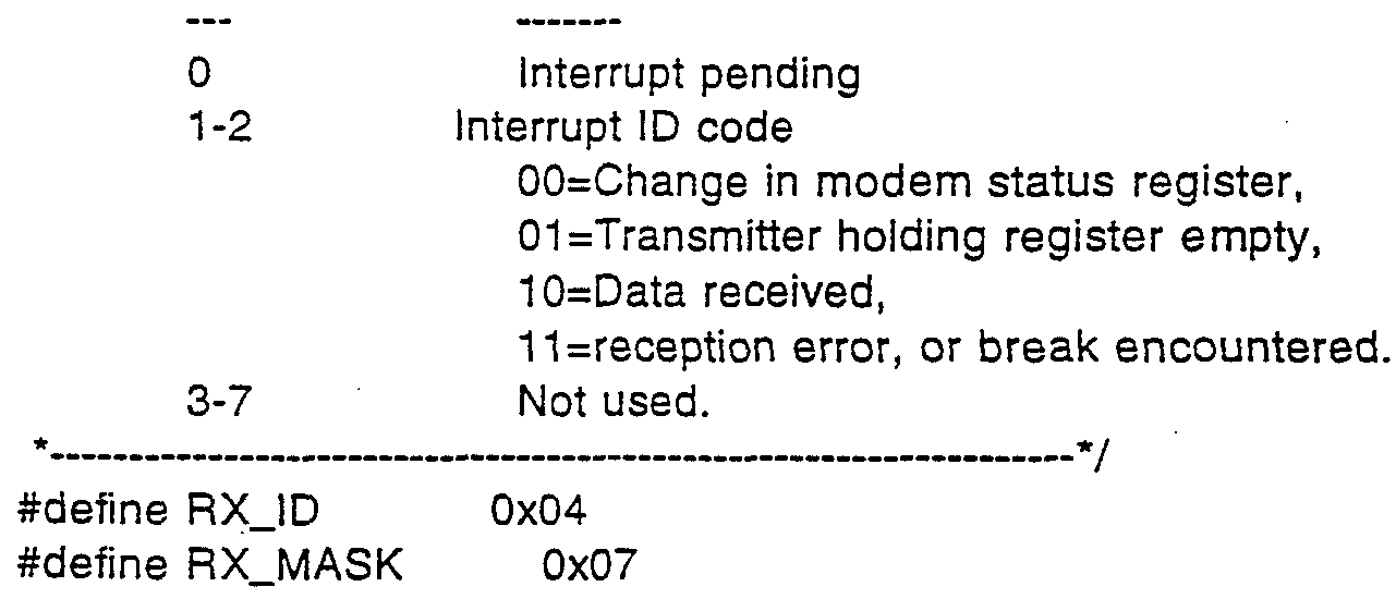
  • o IER Controls interr ⁇ t generation.
  • o MR Identifies interr. > .s. o MCR Send contort signals to the modem.
  • o LSR Monitor the status of the serial port.
  • the (IMR) tells the (PIC) to service an interrupt only if it is not masked (FALSE). 7
  • the (IMR) tells the (PIC) to service an interrupt only if it is not masked (FALSE). 7
  • the 8250 UART has 10 registers accessible through 7 port addresses. Here are their addresses relative to COM1 BASE and COM2BASE. Note that the baud rate registers, (DLL) and (DLH) are active only when the Divisor-Latch Access-Bit (DLAB) is on. The (DLAB) is bit 7 of the (LCR). o TXR Output data to the serial port. o RXR Input data from the serial port. o LCR Initialize the serial port. .. o IER Controls interrupt generation. o IIR Identifies interrupts. o MCR Send contorl signals to the modem. o LSR Monitor the status of the serial port. o MSR Receive status of the modem. o DLL Low byte of baud rate divisor. o DHH High byte of baud rate divisor. 7
  • MSR Modem Input Status Register
  • TBL BAUD 300 1 #def ⁇ ne TBL_BAUD_150 0 #defi ne TBL_PARITY_NONE 0 #defi ne TBL_PARITY_ODD 1 #defi ne TBL_PARITY_EVEN 2 #defi ne TBL_STOPBITS_1 0 #defi ne TBL_STOPBITS_2 1 #defi ne TBL_DSR_MONITOR_OFF 0 #defi ne TBL_DSR_MONITOR_ON 1 #defi ne TBL_DATALENGTH_7 0 #defi ne TBL_DATALENGTH_8 1 #defi ne TBL_TRANSFER_RATE_MAX 7 #defi ne TBL_TRANSFER_RATE_100 6 #defi ne TBL_TRANSFER_RATE_67 5 #defi ne TBL_TRANSFER
  • arr_new[ind_new] arr_old[num_old-1] ;
  • Procedure elev calculates the SIN and COS of the angle of elevation 7 void elev ( float x , float y , float z , float *cos_ug , float * sin_ug )
  • norma (float) sqrt ( x * x + y * y + z * z ) ; if ( norma ⁇ .00001 ) ⁇
  • *cos_ug ( x1 * x2 + y1 * y2 + z1 * 72. ) I normal / norma2 ;

Abstract

Information input apparatus (10, 40, 50, 60, 70) including body supported apparatus (10) for sensing voluntary body motions and providing an output indication thereof, a symbol output interpreter (140) operative to utilize the output indication for providing symbol outputs, and a motion output interpreter (140) operative to utilize the output indication for providing motion control outputs.

Description

IMPROVED INFORMATION INPUT APPARATUS
FIELD OF THE INVENTION
The present invention relates to input devices far computers generally.
BACKGROUND OF THE INVENTION
U.S. Patent 4,787,051 to Olson describes an inertial mouse system which uses three pairs of acceler- ometers.
U.S. Patent 4,839,836 to LaBiche et. al. de¬ scribes an apparatus for providing spatA.i orientation data signals, using an inertial platform accelerometer cluster having a plurality of accelerometers.
U.S. Patent 5,181,181 to Glynn describes a computer apparatus input device for three-dimensional information.
SUMMARY OF THE INVENTION
The present invention seeks to provide an improved input device.
There is thus provided in accordance with a preferred embodiment of the present invention information input apparatus including body supported apparatus for sensing voluntary body motions and providing an output indication thereof, a symbol output interpreter operative to utilize the output indication for providing symbol outputs, and a motion output interpreter operative to utilize the output indication for providing motion con¬ trol outputs.
Further in accordance with a preferred embodi¬ ment of the present invention, the output indication represents features of body motion including features which are characteristic of the individual.
Still further in accordance with a preferred embodiment of the present invention, a mode selector is provided which is operative to cause a selected one of the symbol output interpreter and the motion output interpreter to function.
Further in accordance with a preferred embodi¬ ment of the present invention, the body supported appara¬ tus is a hand held device.
Still further in accordance with a preferred embodiment of the present invention, the body supported apparatus is a generally pen-shaped device.
Additionally in accordance with a preferred embodiment of the present invention, the generally pen- shaped device is operative to provide a visible writing function.
Still further in accordance with a preferred embodiment of the present invention, the information input apparatus also includes an object whose motion is controlled by the motion control outputs.
Further in accordance with a preferred embodi¬ ment of the present invention, the object is a graphic object displayed on a display or a physical object.
Further in accordance with a preferred embodi¬ ment of the present invention, the symbol outputs repre¬ sent alphanumeric symbols or a sensory quality such as an acoustic stimulus, including but not limited to music, or such as a visual stimulus, including but not limited to a color or a color image.
It is appreciated that the applicability of the present invention is very broad and is suitable for the following fields of use, inter alia: games such as video games, toys, model vehicles, robotics, simulations such as flight simulations, tecnnical drawings and CAD.
Still further in accordance with a preferred embodiment of the present invention, the information input apparatus also includes a computer, having a loca¬ tion input and a symbol input, and a display operated by the computer and wherein the symbol outputs represent information to be displayed on the display and the motion outputs are supplied to the location input and are em¬ ployed by the computer to govern the location of the information on the display.
Further in accordance with a preferred embodi¬ ment of the present invention, the symbol outputs include function commands.
There is also provided, in accordance with a preferred embodiment of the present invention, a method by which a manipulable device provides an output indica¬ tion representing its own angular mot: ,.n, the method including recording actual acceleration data from a plurality of accelerometers mounted in the manipulable device, generating predicted acceleration data on the basis of hypothetical angular motion information, compar¬ ing the predicted acceleration data to the actual accel- eration data, computing improved hypothetical angular motion information, repeating, while the predicted accel¬ eration data differs significantly from the actual accel¬ eration data, the generating, comparing and computing steps, and providing an output indication of the improved hypothetical angular motion information.
Further in accordance with a preferred embodi¬ ment of the present invention, the angular motion infor¬ mation includes angular displacement information, angular velocity information and angular acceleration informa¬ tion.
Still further in accordance with a preferred embodiment of the present invention, the method includes computing linear motion information from the improved hypothetical angular motion information and from the actual acceleration data.
Additionally in accordance with a preferred embodiment of the present invention, recording includes recording from at least four accelerometers mounted in the manipulable device, wherein the accelerometers ' each have a center of mass and wherein the centers of mass do not lie within a single plane..
Still further in accordance with a preferred embodiment of the present invention, the method also includes receiving the output indication of the improved hypothetical angular motion information and manipulating an object in accordance therewith.
There is additionally provided, in accordance with a preferred embodiment of the present invention, an accelerometer array mounted in a manipulable device and including at least four accelerometers each having a center of mass, wherein the centers of mass do not lie within a single plane, and a manipulable device motion computer receiving input from the accelerometers and generating an output signal indicative of the motion of the manipulable device. Further in accordance with a preferred embodi¬ ment of the present invention, the manipulable device motion computer is operative to: record actual acceleration data from the accel¬ erometers, s generate predicted acceleration data on the basis of hypothetical angular motion information, compare the predicted acceleration data to the actual acceleration data, compute improved hypothetical angular motion information, repeat, while the predicted acceleration data differs significantly from the actual acceleration data, the generating, comparing and computing steps, and provide an output indication of the improved hypothetical angular motion information.
Further in accordance with a preferred embodi¬ ment of the present invention, the apparatus also includ¬ ing an object manipulator receiving the output signal indicative of the motion of the manipulable device and manipulating an object in accordance therewith.
There is also provided, in accordance with a preferred embodiment of the present invention, an infor¬ mation input method including se_-_;ing voluntary body motions and providing an output indication thereof, utilizing the output indication for providing symbol outputs, and utilizing the output indication for provid¬ ing motion control outputs. BRIEF DESCRIPTION OF THE DRAWINGS
The present invention will be understood and appreciated from the following detailed description, taken in conjunction with the drawings in which: s Fig. 1 is a simplified pictorial illustration of object control and handwriting recognition apparatus constructed and operative in accordance with a preferred embodiment of the present invention;
Figs. 2A and 2B are schematic drawings of preferred structures of portions of the apparatus of Fig.
1;
Fig. 3 is a simplified block diagram of the apparatus of Fig. 1;
Fig. 4 is a simplified flow chart illustrating the object control process performed by the apparatus of Fig. 1;
Fig. 5A is a simplified flow chart illustrating the process of step 440 of figure 4;
Fig. 5B comprises mathematical equations illus¬ trating the process performed by Fig. 5A;
Fig. 6 is a simplified block diagram of the apparatus of Fig. 1;
Fig. 7A is a simplified flow chart illustrating the teaching process performed by the apparatus of Fig. l;
Fig. 7B is a simplified flow chart illustrating the recognition process performed by the apparatus of Fig. 1; and
Figs. 8A and 8B are graphical illustrations useful in understanding a preferred method for a portion of the teaching and recognition processes performed by the apparatus of Fig. 1.
Appendix A is a computer listing of a preferred software implementation of a portion of steps 720 of Fig. 7A and 800 of Fig. 7B. DETAILED DESCRIPTION OF PREFERRED EMBODIMENTS
Reference is now made to Fig. 1 which is a ; --plified pictorial illustration of apparatus operative t perform motion control in synergistic combination with symbol interpretation such as handwriting recognition. A hand-held pen 10 is operative to be translated and rotat¬ ed about some or all of three perpendicular axes. The term "six degrees of freedom" is used herein to designate translation along and rotation about three orthogonal axes.
Pen 10 also comprises a plurality of built-in accelerometers 25, such as model ICS 3031-2 commercially available from IC Sensors, 1701 McCarthy Blvd., Milpitas, CA 95035. Preferably, pen 10 comprises six accelerome¬ ters arranged in pairs, with each pair lying along a particular axis, with the axes being mutually orthogonal. Alternatively, the axes may not be mutually orthogonal. In any case the accelerometers need not be coplanar.
Pen 10 also comprises a plurality of amplifiers 30, associated with the plurality of accelerometers 25. Fig. 2A is a schematic drawing of a preferred embodiment of amplifier 30.
Alternatively, removable apparatus comprising a plurality of accelerometers 25 as described above, and also comprising associated amplifiers 30, as described above, may be retrofitted onto the pen 10. The removable apr ratus may have the form of a cap fitting the end of the pen, a ring fitting over the pen, or any other suit¬ able form.
In a still further alternative, the apparatus may not include a pen, but may have any other suitable hand held form. In a yet further alternative, the appa¬ ratus may be in the form of a ring fitting the user's finger, may be supported by the body of a user, or mount¬ ed thereupon in any suitable matter. Pen 10 also comprises a switch 35, which can be used to send a signal indicating whether pen 10 is being used for handwriting recognition or as a pointing and control device. Alternatively the signal may be sent by moving pen 10 in a predefined format, or by any other appropriate means. During handwriting recognition, the user may write with pen 10 on writing surface 37.
The data from the plurality of accelerometers 25 in pen 10 is termed herein "accelerometer data". The accelerometer data is sent through a cable to a control circuit 40. Alternatively, the accelerometer data may be sent through any suitable wireless communication link, such as ultrasonic, infrared, or by any other suitable means.
Control circuit 40 amplifies the acceleration signals from pen 10 and converts them to digital form, preferably using an analog to digital converter. Fig. 2B is a schematic drawing of a preferred embodiment of an analog to digital converter suitable for the present application.
Control circuit 40 then sends acceleration data to a CPU 50. CPU 50 may be any suitable CPU such as an IBM PC compatible computer with an 80386 processor chip.
Associated with CPU 50 are a screen 60 and a keyboard 70. An object 80, such as a cursor or a graphic representation of a physical object, is displayed on screen 60. When pen 10 is used for object control, CPU 50, based on the acceleration data, moves the cursor or graphic representation 80 with six degrees of freedom, corresponding to the movement of pen 10.
A symbol 85, such as one or more characters or words, may also be displayed on screen 60. When pen 10 is used for handwriting recognition, CPU 50, based on the acceleration data, displays the symbols corresponding to what is written on writing surface 37 on screen 60.
The functionality of the apparatus of Fig. 1 will now be described. Using switch 35 the user indi¬ cates whether handwriting recognition or object control is to be performed. Depending on the user's choice, the apparatus of Fig. 1 performs the appropriate function.
The functionality of the apparatus of Fig. 1 when performing obj*- v. control will now be briefly de¬ scribed. The user moves pen 10 in three dimensions; the motion may include six degrees of freedom. Pen 10 sends acceleration data describing the accelerations of pen 10 during the motion to control circuit 40.
Control circuit 40 amplifies and digitizes the acceleration data. The data is sent by control box 40 to CPU 50.
CPU 50 computes the translational displacement, velocity, and acceleration of pen 10 along three mutually perpendicular axes which axes need have no relation to the axes of the accelerometers. CPU 50 also computes the angular displacement (rotation) , velocity and accelera¬ tion of pen 10 around the same three mutually perpendic¬ ular axes.
Based on the computed output, CPU 50 moves the cursor or the representation of an object 80 on screen 60 with translations and rotations corresponding to those of pen 10. The axes for the translation and rotation of the cursor or object correspond to the axes used to compute the translation and rotation of pen 10.
Reference is now additionally made to Fig. 3 which is a simplified block diagram of the apparatus of Fig. 1. Pen 10, when moved by the user with six degrees of freedom, transmits data describing the accelerations of pen 10 to amplification circuit 120. Amplification circuit 120 amplifies the acceleration data and transmits the amplified acceleration data to analog/digital con¬ verter 130. Analog/digital converter 130 digitizes the acceleration data and transmits the digitized data to displacement/velocity/acceleration computation apparatus 140, termed herein DVA 140.
DVA 140 computes the angular displacement, velocity, and acceleration of pen 10 around three mutual¬ ly perpendicular axes which axes need have no relation to the axes of the accelerometers. DVA 140 also computes the translational displacement, velocity and acceleration of pen 10 along the same three mutually perpendicular axes.
DVA 140 transmits data describing the six degrees of freedom to screen display control 150. Based on the data, screen display control 150 updates screen 60 to show the new location and orientation of the cursor or the other object depicted on screen 60.
Reference is now additionally made to Fig. 4 which is a simplified flow chart illustrating operation of the apparatus of Fig. 1 in accordance with a preferred embodiment of the invention. The preferred method of operation of the method of Fig. 4 includes the following steps:
STEP 410: Read accelerometer data. Data from each of the plurality of accelerometers 25 is sampled, preferably at a rate of one thousand data points per second.
STEP 412: Check whether session is at the beginning. At the beginning of a session, STEP 420, described below, is required.
STEP 415: Check whether pen is in motion. The accelerometer data is analyzed to determine whether pen 10 is in motion.
Preferably, pen 10 is considered to be not in motion whenever all of the acceleration signals indicate that the only sensed accelerations are due to gravity. Signals are chosen from one member of each of three pairs of accelerometers, each pair arranged along a different axis.
Let the vector U=(U^,U2,U3) denote the signals of the three accelerometers. Let the matrix A=(K1,K2,K3) denote the sensitivities of each of the three accelerome¬ ters.
The sensitivities of the accelerometers correct for any deviations of the axes of each pair of accelerom¬ eters as they are actually mounted in pen 10 from the common axis on which they are supposed to be situated; this component of the sensitivity is called static sensi¬ tivity. The sensitivities also correct for deviations between the axes of the global orthogonal coordinate system and the axes of the pairs of accelerometers; this component of the sensitivity is called dynamic sensitivi¬ ty. In actual practice, both static sensitivity and dynamic sensitivity may make important contributions to sensitivity.
The static sensitivity is computed as part of step 420, described in detail below. The dynamic sensi¬ tivity is computed as part of step 455, described in detail below.
Let _ denote a small positive constant; for example, .005g where g denotes the acceleration of gravi¬ ty at the earth's surface. Then the pen is considered not to be in motion whenever l-_ < |A-1U| < 1+e.
STEP 420: Compute initial conditions. The initial con.' .tions may comprise the initial Euler angles between the -lobal coordinate system and the axes of the pairs of accelerometers. These Euler angles are now determined.
Assuming that, at the initial condition, either at the beginning of the session or when the pen is not in motion, the only accelerations measured are due to gravi¬ ty, the static sensitivity can be computed from the accelerometer data while the pen is at rest in three known orientations. Alternatively, the static sensitivi¬ ty can be computed once as a property of the pen and stored for future use. STEP 430: Compute the differential signal from each pair of accelerometers. The signals from each member of each pair of accelerometers are subtracted to form a differential signal for each pair of accelerome¬ ters.
STEP 440: Compute rotational parameters. The rotational parameters define parameters of the motion about the three axes of the global coordinate system. The rotational parameters comprise the three Euler angles; the three angular velocities; and the three angular accelerations.
The rotational parameters are computed in parallel using an iterative feedback loop. In each iteration of the loop, an estimated differential acceler¬ ation is computed from the current rotational parameters. If the difference between the estimated differential acceleration and the actual differential acceleration signal is less than a predetermined amount, iteration is terminated.
Otherwise, new values of the parameters are estimated in each iteration from the previous values and the difference between the estimated differential accel¬ eration and the actual differential acceleration data. The method of this step is described more fully below with reference to Fig. 5.
STEP 450: Compute translation acceleration. The angular orientation and the angular acceleration are known from step 440. From the angular orientation and the sensitivity vector the acceleration due to gravity is computed.
Given the angular acceleration and the acceler¬ ation due to gravity as well as the sensitivity vector, the translational acceleration is computed. The computa- tion is according to the formula a^=K u-a(-.-ar where a^. is the translational acceleration; K is the sensitivity vector; u is the signal of one accelerometer; ag is the component of the acceleration of gravity sensed by the one accelerometer; and ar is the angular acceleration.
STEP 455: Update dynamic sensitivity. As explained above, the dynamic sensitivity represents deviations between the axes of the global orthogonal coordinate system and the axes of the pairs of accelerom¬ eters. Since the angular orientation of pen 10 may have changed, the dynamic sensitivity may also have changed.
Given the change in the angular orientation of pen 10, the new dynamic sensitivity may be computed from the new angular orientation and the old matrix of dynamic sensitivity.
STEP 460: Compute translational velocity and displacement. The translational velocity is computed by integrating the translational acceleration with respect to time. The displacement is computed by integrating the translational velocity with respect to time.
STEP 470: Move screen object. Based on the output of previous steps which comprises translational acceleration, velocity and displacement as well as angu¬ lar acceleration, velocity and orientation, the screen object is moved. The moving of the screen object may be according to any appropriate transformation of the mo¬ tions of pen 10.
Reference is now additionally made to Fig. 5A which is a simplified flowchart illustrating to operation of step 440 of Fig. 4. Fig. 5A includes the following steps:
STEP 480: Set initial parameters. The rota¬ tional parameters comprise the three Euler angles; the three angular velocities; and the three angular accelera¬ tions. The initial value for the Euler angles is comput¬ ed based on the previously known value of the parameters, assuming that the acceleration has remained constant.
STEP 482: Compute differential acceleration from model. First the position of an accelerometer in the coordinate system of the pen is defined by vector r and the rotation of the pen in the global coordinate system is defined by a rotation matrix A(phi) . For example, A(phi) may be an appropriate rotation matrix as presented in sections 14.10-5 through 14.10-7, pages 475- 48TJ of Mathematical Handbook for Scientists and Engineers by Korn and Korn, 2nd Edition, published by McGraw-Hill in 1968. Here phi is a vector of Euler angles: phi=(α,β,r)τ. Then the position of the accelerometer in the global coordinate system R is defined by R=Ar.
Reference is hereby additionally made to Fig. 5B, which contains equations useful for understanding the steps of Fig. 5A. Equation 490 illustrates the computa¬ tion of the acceleration of the accelerometer in the global coordinate system.
As the Euler angles of the accelerometer change, the sensitivity vector K also changes. The change in the sensitivity vector K may be computed by using equation 492 of Fig. 5B.
Given the acceleration of the accelerometer and the new sensitivity vector, the estimated value for the differential signal of the accelerometer, ues . may be computed by using equation 494 of Fig. 5B.
The remainder of the parameters may be computed with an appropriate model. Preferably, a model which allows the use of only the parameters specified above, rather than a larger number of parameters, is used. For example,, equation 496 of Fig. 5B represents an appropri¬ ate model for computing the remainder of the parameters.
STEP 484: Is the difference between the com¬ puted and the current value less than a predetermined amount? If the difference is less than this amount, the estimated parameters are taken to be correct and itera¬ tion is terminated, with the computed parameters being reported.
An appropriate value for the predetermined amount may vary depending on, for example, the maximum number of desired iterations. One possible appropriate value would be .0003 g, where g represents the accelera¬ tion of gravity at the earth's surface.
STEP 486: Compute changes in estimated angles according to the gradient method. New estimated angles are computed by adding a change to the old estimated angles; the change is computed according to the gradient method. The gradient method is explained more fully in section 20.3-3 of Mathematical Handbook for Scientists and Engineers by Korn and Korn, referred to above.
STEP 488: Compute new parameters. New values for the remaining parameters are computed. Iteration then continues with step 482.
The functionality of the apparatus of Fig. 1 when performing handwriting recognition will now be briefly described. Pen 10 sends acceleration data through . control circuit 40 to CPU 50. Teaching and recognition then occur based on the data from pen 10.
Reference is now additionally made to Fig. 6 which is a simplified block diagram of the apparatus of Fig. 1 when used for handwriting recognition. The appa¬ ratus of Fig. 6 receives input from pen 10.
Pen 10, when moved by the user of the handwrit¬ ing recognition apparatus, transmits data describing the accelerations of pen 10 over time to acceleration teach¬ ing control 630 and/or acceleration handwriting recogni¬ tion control 650.
The data from pen 10 may be transmitted to acceleration teaching control 630. Transmission to accel¬ eration teaching control 630 typically occurs for each person who is to use the system for handwriting recogni¬ tion for the first time. Transmission to acceleration teaching control 630 also preferebly occurs when recogni¬ tion errors are detected; use of acceleration teaching control 630 when recognition errors are detected is termed herein adaptive teaching.
Acceleration teaching control 630 operates on the data received, which data represents hand movements by the user when writing a symbol, together with manual¬ ly-provided identification of the symbol codes that are associated with the data. Acceleration teaching control 630 then updates database 640, a per-person per-symbol acceleration database. Database 640 comprises prototypes of accelerations for each symbol, comprising data specif¬ ic to each person for each symbol.
Alternatively, the data from pen 10 may be transmitted to acceleration handwriting recognition control 650. Acceleration handwriting recognition con¬ trol 650 operates on the data received from pen 10 to recognize the symbol represented by the movement of pen 10.
The output of acceleration handwriting recogni¬ tion control 650 comprises a list of symbol codes and their respective probabilities. An acceleration hand¬ writing recognition post-processing circuit 660, chooses the correct symbol code based on the list of symbol codes and probabilities, and on post-processing information which preferably comprises a database of previous confu¬ sions and a dictionary. The output of acceleration hand¬ writing recognition post-processing circuit 660 is a list of symbol codes and/or words sorted by likelihood.
Reference is now additionally made to Figs. 7A and 7B which are simplified flow charts illustrating operation of the apparatus of Fig. 7 in accordance with a preferred embodiment of the invention, when performing handwriting recognition. Fig. 7A illustrates the teach¬ ing process and Fig. 7B illustrates the recognition process. The steps in Fig. 7A include the following:
STEP 710: Read accelerometer data. The accel¬ erometer data comprises data points representing sampling of the acceleration measured by accelerometers 25. Preferably, the sampling rate is approximately 1600 data points per second, averaged over 8 points, producing an output of approximately 200 data points per second.
STEP 712: Identify pen-surface contact termi¬ nation. The data from step 710 does not include the surface contact status of pen 10. The surface contact status of pen 10 may be derived from the acceleration data as follows:
The acceleration data is filtered to remove components other than noise. For example, the accelera¬ tion data may be filtered by a Butterworth digital filter described in Digital Filter Design by T.W. Parks and C.S Burrus, John Wiley & Sons, 1987, chapter 7, section 7.3.3, using the 4th order lowpass digital filter with a cut-off frequency of 0.7 to 0.9.
The filtered acceleration data is then inte¬ grated over time. The slope of the integrated filtered acceleration data is then analyzed to determine the point at which the slope exceeds a threshold value. The point at which the slope exceeds the threshold value is taken to be the first point with status "pen down". The point at which the slope falls below a threshold value is taken to be the first point with status "pen up"; the threshold value may or may not be the same as the previously de¬ scribed threshold value.
The threshold values described above may be determined in advance for the particular type of pen and writing surface, may be determined by a learning process for the particular person, or may be determined by other means.
STEP 715: Identify individual symbols and words. The data from the previous step is divided into data representing individual symbols. The status which comprises the status of "pen up" is termed herein "pen not down" . Preferably, the number of consecutive data points with status of "pen not down", which data points represent a particular duration of the status "pen not down" is taken to indicate the end of a symbol or of a word.
Typically, the duration of status "pen not down" within a range from 200 milliseconds to 400 milli- se*conds is taken to indicate the end of a symbol. Dura¬ tion of the status "pen not down" in the range from 800 milliseconds to 1200 milliseconds is typically taken to indicate the end of a word.
Alternatively, the end of a symbol or of a word may be indicated by data points which represent pen movements that are not part of a symbol, or by other means. Output data from step 715 comprises symbol end and word end data.
STEP 720: Normalize accelerometer data. The accelerometer data is normalized in time or by other means. Appendix A is a computer listing in the C pro¬ graming language comprising routines that are a preferred implementation of step 720. The routines comprise the following routines in section II, "pre-preprocessing": normal; together with various definitions used by routine normal.
STEP 730: Filter accelerometer data. The normalized accelerometer data received from the previous step is filtered in order to remove noise. The filtering may be accomplished by iterative smoothing of adjacent points until the total change in the signal due to a smoothing operation is less than the desired accuracy of the data, or by other suitable means.
STEP 740: Parameterize accelerometer data. The data is parameterized according to criteria which are chosen .to represent each symbol. If the accelerometers are not mutually orthogonal, the acceleration data may be converted into equivalent data in a mutually orthogonal coordinate system as follows:
Let the non-orthogonal signals be denoted by the vector u=(u.]_,u2,u3) and the orthogonal signals be denoted by the vector u'-^u'^ '^ '-j)"-. Then u'=A0A~-u where A is a vector of static sensitivity vectors A=(A1,A2,A3) of the three accelerometers. The static sensitivity vector is computed from the outputs of the accelerometers during a defined orientation without movement. A- is a diagonalized matrix of sensitivity of the orthogonal coordinate system comprising the norms of A^, A2, and A3.
The parameters preferably comprise the follow¬ ing: number of points before normalization; normalized signal of pen status; normalized signal of Z acceleration; sine of the angle a ' which angle is defined as the angle between the vector associated with the current data point (AccXj_,AccYj_,AccZ^) and the AccXAccY plane as shown in Fig. 8A; cosine of the angle ' ; sine of the angle β' which angle is defined as the angle between the vector that connects the point before the previous data point (AccX__ ,AccY^_2,ACCZJ_2) and the current point (AccXj_,AccY^,AccZj_) , and the vector that connects the current point with the point after the subsequent point (AccXi+2,AccYi+2,AccZi+2) in space (AccX,AccY,AccZ) as shown in Fig. 8B; and cosine of the angle β'.
STEP 750: Generalize parameters. The parame¬ ters of the symbol being learned represent a specific instance of the symbol. The symbol prototype stored by the system is to represent the general characteristics of the symbol as drawn by that person. Therefore, the parameters of the symbol being learned are generalized by some suitable means, such as by computation of the aver¬ age of the value of each parameter from previous in¬ stances of the symbol along with the value of each param- eter from the current instance of the symbol.
STEP 760: Update per-person per-symbol accel¬ eration prototype database. The newly computed parame¬ ters from the previous step are stored in the per-person per-symbol acceleration prototype database.
The steps in Fig. 7B include steps which have already been described above with reference to Fig. 7A. The remainder of the steps in Fig. 7B include the follow¬ ing:
STEP 800: For each prototype in the per-person per-symbol acceleration prototype database, build a measure ' of comparison between the sample and the proto¬ type, combined over parameters in the prototype. In accordance with a preferred embodiment of the present invention, all parameters are combined together to pro¬ duce the measure of comparison. Appendix A is a computer listing in the C programing language comprising routines that are a preferred implementation of step 800. The routines comprise the following, which are found in section V, "symbols recognition": make_corr; correl_hem; obj_funct; together with various definitions used by the routines.
STEP 810: Create a list of probable symbols sorted by likelihood. Based on the measure or measures of comparison generated in step 800, a single list of probable symbols sorted by likelihood is generated.
STEP 820: Choose the correct symbols and the correct word based on the list, the database of previous confusions and a dictionary. The symbols with greatest likelihood are the candidates from which the correct symbol is chosen.
The database of previous confusions provides information that allows the correction of the choice of the correct symbol based on previous incorrect identifi¬ cations. The database of previous confusions comprises, for each symbol, a list of other symbols which have been confused with the first symbol; for example, that the symbol "f" has often been confused with the symbol "b" . When such an entry is found comprising previous confu¬ sions for a symbol in the list, the symbol or symbols that have previously been confused with the symbol in the li"st are added to the list. In accordance with the previous example, if the symbol "f" is found in the list, then the symbol "b" is added to the list.
An indication of the end of each word has been passed as output since step 715, described above. Based on the indication, the most likely word, comprising the most likely identifications for each symbol in the list, is identified.
The most likely word is checked against the dictionary. Preferably, the dictionary comprises both a general dictionary used for all users of the system and a personal dictionary for each user of the system. If an entry exists in the dictionary for the most likely word, the word is chosen as the correct identification.
If the most likely word is not found in the dictionary, all possible word combinations in the list are formed and each is checked against the dictionary. Among all such words which are found in the dictionary, the word with the highest likelihood is then chosen as the correct identification.
If none of the words is found in the diction¬ ary, the most likely word is chosen as the correct iden¬ tification.
STEP 830: Check to see if a correction has been entered. During the process of recognition, the user of the system is preferably provided with a visual indication of each symbol recognized.
After the end of a word is detected, the user of the system preferably is provided with a visual indi¬ cation of the word recc αized. The user may indicate manually that a given word was incorrectly recognized and may input a correction.
STEP 840: Update database of previous confu¬ sions. Based on a manual correction entered in step 830 or an automatic correction based on the dictionary, the database of previous confusions is updated. Based on a manual correction, the personal dictionary is also updat¬ ed if the corrected word is not found in the dictionary.
Preferred methods and apparatus for handwriting recognition are described in the following applications, the disclosure of which is hereby incorporated by refer¬ ence: PCT/US92/08703; Israel 104575; PCT application filed 31 January 1994 in the US Receiving Office by Ehud Baron and Edward A. Wolfe.
It is appreciated that the particular embodi¬ ment described in Appendix A is intended only to provide an extremely detailed disclosure of the present invention and is not intended to be limiting.
It is appreciated that various features of the invention which are, for clarity, described in the con¬ texts of separate embodiments may also be provided in combination in a single embodiment. Conversely, various features of the invention which are, for brevity, de¬ scribed in the context of a single embodiment may also be provided separately or in any suitable subcombination.
It will be appreciated by persons skilled in the art that the present invention is not limited to what has been particularly shown and described hereinabove. Rather, the scope of the present invention is defined only by the claims that follow: APPENDIX A Recognition according a combination of signals
Definitions and data structures
Board. H file
/* Function init_datatr ( portbase ) sets communication with data translation board via port portbase. it returns :
0 - communication was established ; -1 - error on board (board is not exist). */ //int init_datatr ( int ) ; int newcomp ( void ) ; int read_ch ( int channel , int gain ) ;
//int read_point ( struct point * , in ) ; int read_block ( struct point * , int max_numb_point , int timeout_for_begin , int timeout_for_end , int key_mouse_stop ) ; */
//int read_symbol ( struct point * , int , int ) ; int mshit ( void ) ; void close_datatr ( void ) ;
#define PORT_BASE 0x210
#define KEY_STOP 0x1 #defiπe MOUSE_STOP 0x2 #define KEY_MOUSE_STOP 0x3
#define PEN_WAiT 0x1 #define PEN NOWAIT 0x0
Data.H file struct point_pen
{ unsigned a ; unsigned ay ; unsigned az ; unsigned pn ;
} ; struct poin ablet
{ int x ; int y ; int p ;
} ;
#define SYNCROBIT Oxεo Datar.H file
#define PORT_BASE 0x210 #define CSR 0x0
^define GAIN 0x1
#define DAC0_LOW 0x2
#define DAC0_HIGH 0x3 #define DAC1_LOW 0x4
#define DAC1_HIGH 0x5
#define CHANNEL. AX 0x4 #define CHANNEL_AY 0x5 #define CHANNEL. A2 0x6 #define CHANNEL_PN 0x7 #define STATUS Oxe
#define CHANNEL_EMPTY 0x0
#define IDREGISTER Oxf
7
Figure imgf000026_0001
#define TIME_COUNT 3000 #include <dos.h> Ser.H file r *
FILENAME: SERIAL.H
Some definitions used by SER.C *
#define COM1 1
#define COM2 2
#define COM1 BASE 0x3F8 /* Base port address for COM1 7
#define CQM2BASE 0x2F8 /* Base port address for COM2 7 r
The 8250 UART has 10 registers accessible through 7 port addresses. Here are their addresses relative tc COM1 BASE and COM2BASE. Note that the baud rate registers, (DLL) and (DLH) are active only when the Divisor-Latch Access-Bit (DLAB) is on. The (DLAB) is bit 7 of the (LCR). o TXR Output data to the serial port. o RXR Input data from the serial port. o LCR Initialize the serial port. o IER Controls interr ~t generation. o MR Identifies interr. > .s. o MCR Send contort signals to the modem. o LSR Monitor the status of the serial port. o MSR Receive status of the modem. o DLL Low byte of baud rate divisor. o DHH High byte of baud rate divisor.
Figure imgf000027_0001
Figure imgf000028_0001
r *
Bit values held in the Interrupt Enable Register (IER). bit meaning
0 Interrupt when data received.
1 Interrupt when transmitter holding reg. empty.
2 Interrupt when data reception error.
3 Interrupt when change in modem status register. 4-7 Not used.
* */
#define RX INT 0x01
I* *
Bit values held in the Interrupt Identification Register (MR), bit meaning
Figure imgf000029_0001
/*
These are the port addresses of the 8259 Programmable Interrupt
Controller (PIC). 7
#define IMR 0x21 /* Interrupt Mask Register port 7
#define ICR 0x20 /* Interrupt Control Port 7
Λ
An end of interrupt needs to be sent to the Control Port of the 8259 when a hardware interrupt ends. 7 #define EOI 0x20 End Of Interrupt 7
The (IMR) tells the (PIC) to service an interrupt only if it is not masked (FALSE). 7
#define IRQ3 0xF7 /* COM2 7
#define 1RQ4 OxEF /* COM1 7
/*
The (IMR) tells the (PIC) to service an interrupt only if it is not masked (FALSE). 7
#define IRQ3 0xF7 /* COM2 7
#define IRQ4 OxEF r COM1 7 int flag; int SetSerial(); int SetOthers(int Parity, int Bits, int StopBit); int SetSpeed(int Speed); int SetPort(int Port); void init_serial(void); void comm_off(void); void setallport(int Port, int Speed, int Parity, int Bits, int StopBit); int putchport (char); void putst.port(char *); int getchport(void); void off port" ;
Serconst.H file '
FILENAME: SERCONST.H
Some definitions used by SER.C
The 8250 UART has 10 registers accessible through 7 port addresses. Here are their addresses relative to COM1 BASE and COM2BASE. Note that the baud rate registers, (DLL) and (DLH) are active only when the Divisor-Latch Access-Bit (DLAB) is on. The (DLAB) is bit 7 of the (LCR). o TXR Output data to the serial port. o RXR Input data from the serial port. o LCR Initialize the serial port. .. o IER Controls interrupt generation. o IIR Identifies interrupts. o MCR Send contorl signals to the modem. o LSR Monitor the status of the serial port. o MSR Receive status of the modem. o DLL Low byte of baud rate divisor. o DHH High byte of baud rate divisor. 7
#define TXR 0 /* Transmit register (WRITE) 7
#define RXR 0 /* Receive register (READ) 7
#define IER 1 /* interrupt Enable 7
#define IIR 2 /* Interrupt ID 7
#define LCR 3 /* Line control 7
#define MCR 4 /* Modem control 7
#define LSR 5 Λ Line Status 7
#define MSR 6 I* Modem Status 7
#define DLL 0 /* Divisor Latch Low 7
#define DLH 1 /* Divisor latch High 7
#define DLAB 0x80 /* 7
/* *
Bit values held in the Line Control Register (LCR). bit meaning
Figure imgf000031_0001
r
Bit values held in the Line Status Register (LSR). bit meaning
0 Data ready. 1 Overrun error - Data register overwritten. 2 Parity error - bad transmission.
3 Framing error - No stop bit was found. 4 Break detect - End to transmission requested.
5 Transmitter holding register is empty. 6 Transmitter shift register is empty.
7 Time out - off line.
#define RCVRDY 0x01 #define OVRERR 0x02 #define PRTYERR 0x04 #define FRMERR 0x08 #define BRKERR 0x10 #define XMTRDY 0x20 #define XMTRSR 0x40 #define TIMEOUT 0x80
/*-
Bit values held in the Modem Output Control Register (MCR). bit meaning
0 Data Terminal Ready. Computer ready to go.
1 Request To Send. Computer wants to send data.
2 auxiliary output #1.
3 auxiliary output #2.(Note: This bit must be set to allow the communications card to send interrupts to the system)
4 UART ouput looped back as input. 5-7 not used. •/
#define DTR 0x01
#define RTS 0x02
#define MC INT 0x08
r *
Bit values held in the Modem Input Status Register (MSR). bit meaning
Figure imgf000032_0001
#define CTS 0x10
#define DSR 0x20
/*.._ *
Bit values held in the Interrupt Enable Register (IER). bit meaning
0 Interrupt when data received.
1 Interrupt when transmitter holding reg. empty.
2 " Interrupt when data reception error.
3 Interrupt when change in modem status register. 4-7 Not used. */
#define RX INT 0x01
I* *
Bit values held in the Interrupt Identification Register (IIR). bit meaning
Figure imgf000032_0002
r
These are the port addresses of the 8259 Programmable Interrupt
Controller (PIC). 7
#define IMR 0x21 /* Interrupt Mask Register port 7
#define ICR 0x20 /* Interrupt Control Port 7
/*
An end of interrupt needs to be sent to the Control Port of the 8259 when a hardware interrupt ends. 7 #define EOI 0x20 /* End Of Interrupt 7
/* The (IMR) tells the (PIC) to service an interrupt only if it is not masked (FALSE). 7 /unsigned char IRQ[8] = { -0x01 , -0x02 , -0x04 , -0x80 ,
-0x10 , -0x 7 #define IRQ3 0xF7 Λ COM2 7
#define IRQ4 OxEF /* COM1 7 int SerSetPortBase ( int , unsigned * ) ; int SerSetSpeed ( unsigned , long ) ; int SerSetBitsParityStopBit ( unsigned , int , int , int ) ; int SerPutChar ( unsigned , unsigned char ) ; int SerPutSlring ( unsigned , unsigned char * ) ; int SerlnitBuffer ( unsigned ) ; int SerGetChar ( unsigned ) ; int SerTestDSR ( unsigned ) ; int SerTestCTS ( unsigned ) ; int flag; int SetSerialO; int SetOthers(int Parity, int Bits, int StopBit); int SetSpeed(int Speed); int SetPort(int Port); void init_serial(void); void comm_off(void); void setallport'int Port, int Speed, int Parity, int Bits, int StopBit); int putchport (char); void putstrport(char *); int getchport(void); void offport'); 7
Tablet.H file
#define PEN_DOWN 1
#define PENJJP 0
#define PEN_OUTPROX 99
#defιne TBL_WACOM_ll 3
#define TBL_DATA_ASCII 1
#define TBL_DATA_BINARY 0
#define TBL_MODE_STREAM 3
#define TBL_MODE_SWITCH_STREAM #define TBL_MODE_SUPRESSED 0
#define TBL_MODE_POINT O
#define TBL_TYPE_ABSOLUTE 0
#define TBL.TYPE^RELATIVE 1
#define TBL_MILLIMETERS 0
#define TBL_INCHES 1
#define TBL_ALWAYS_TRANSMIT_YES 1
#define TBL_ALWAYS_TRANSMIT_NO 0
#define TBL_BAUD_19200 7
#define TBL_BAUD_9600 6
#define TBL_BAUD_4800 5
#define TBL_BAUD_2400 4
#define TBL_BAUD_1200 3
#define TBL_BAUD_600 2
#define TBL BAUD 300 1 #defι ne TBL_BAUD_150 0 #defi ne TBL_PARITY_NONE 0 #defi ne TBL_PARITY_ODD 1 #defi ne TBL_PARITY_EVEN 2 #defi ne TBL_STOPBITS_1 0 #defi ne TBL_STOPBITS_2 1 #defi ne TBL_DSR_MONITOR_OFF 0 #defi ne TBL_DSR_MONITOR_ON 1 #defi ne TBL_DATALENGTH_7 0 #defi ne TBL_DATALENGTH_8 1 #defi ne TBL_TRANSFER_RATE_MAX 7 #defi ne TBL_TRANSFER_RATE_100 6 #defi ne TBL_TRANSFER_RATE_67 5 #defi ne TBL_TRANSFER_RATE_50 4 #defi ne TBL_TRANSFER_RATE_20 3 #defi πe TBL_TRANSFER_RATE_10 2 #defi ne TBL_TRANSFER_RATE_5 1 #defi ne TBL_TRANSFER_RATE_1 0 #defi ne TBL_ORIGINLOG_UPPER_LEFT 1 #defi ne TBL_ORIGINLOG_LOWER_LEFT 0 #defi ne TBL_DATA_TERMlNATOR_CR_LF 2 #defi ne TBL_DATA_TERMINATOR_LF 1 #defi ne TBL DATA TERMINATOR CR 0
iπt read_point_tablet_pen ( unsigned , int , struct point_tablet * , struct point_pen *[8] ) iπt find_set_parameters_tablet ( int comport , unsigned *portbase ) ; int init.tablet ( int port , unsigned *portbase , int command_set , int data.format , int operation_mode , int origin_type int unit_mesure , int always_transmit , int speed , int parity , int stopbit , int dsr_ monitor , int datalength , int t.ansfer_rate , int origjog , int data.terminator , int max_x , int max_y ) ; void close.tablet ( unsigned portbase ) ;
I. Reading from device
/* This procedure reads synchronized data from the graphic tablet and accelerometers /* int read_point_tablet_pen ( unsigned portbase , int read_pen , struct point_tablet "tablet , struct point_pen pen[8] )
{ int ind_package = 0 , reply , debug[10] , i ; unsigned char package[7] = { 0 , 0 , 0 , 0 , 0 , 0 , 0 } ; if ( read.pen ) read_point_pen ( &pen[0] ) ; i= 0 ;
/* Waiting for synchro-bit 7 do
{ if ( ( reply = SerGetChar ( portbase ) ) < 0 ) return reply ; debug[i÷+] = reply ; if ( ( package[0] = (char) reply ) & SYNCROBIT ) break ; } while ( ind_package++ < 10 ) ;
/* Error - No synchro-bit in 10 bytes 7 if ( ind_package >= 10 ) return SER.SYNCROBIT ;
Λ Read the next 6 bytes from tablet and 6 points from accelerometer 7 for ( ind_package = 1 ; ind.package < 7 ; ind_package++ )
{ if ( read.pen )
{ read_point_pen ( &pen[ind_package] ) ;
} if ( ( reply = SerGetChar ( portbase ) ) < 0 ) return reply ; package[ind_package] = (char) reply ; }
/* Read last point from accelerometer 7 if ( read_peπ ) read_point_pen ( &pen[ind_package] ) ;
/* Calculates the values of the signals for tablet 7 tablet->x = ( package[0] & 0x03 ) « 14 ; tabiet->x τ= ( package[1] & 0x7f ) « 7 ; tablet->x ÷= ( package[2] & 0x7f ) ; if ( package[0] & 0x04 ) tablet->x = - tablet->x ; tablet->y = ( package[3] & 0x03 ) « 14 ; tablet->y += ( package[4] & 0x7f ) « 7 ; tablet->y += ( package[5] & 0x7f ) ; tablet->p = 0 ; if ( ! ( package[0] & 0x40 ) ) tablet->p = 99 ; if ( package[3] & 0x04 ) tablet->y - - tablet->y ; if ( package[6] & 0x20 ) tablet->p = ( package[6] & 0x1 f ) ; return 0 ;
II. Pre-processing
/* Two procedures: Normalization in time and filtering the input signals by smoothing
7 void normal ( int num_old , float arr_oldQ , int num_new , float arr_newQ )
{ double koeff ; int ind_old , ind_new ; koeff = (double) ( num_old - 1 ) / (float) ( num_new - 1 ) ; arr_new[0] = arr_old[0] ; for ( ind.new = 1 ; ind_new < num_new - 1 ; ind_new ++ ) { ind_old = (int) ( floor ( koeff * ind_new ) ) ; arr_new[ind_new] = ( ind.old + 1 - koeff * ind_new ) * arr_o!d[ind_old] + ( koeff * ind.new - ind_oId ) * arr_old[ind_old + 1] ; arr_new[ind new] = arr_newfind_new] ;
} arr_new[ind_new] = arr_old[num_old-1] ;
)
float smoothl ( int num , float z~ )
{ int ind ; float temp ; float norma ; for (ind = 1 , norma = 0 ; ind < num - 1 ; ind++ ) { temp = ( z[ind -1]+z[ind]+z[ind+1] ) /3. ; norma += abbs ( z[ind] - temp ) ; z[ind] = temp ;
} return norma ;
} 111. Parameter's extraction
/* Calculation of the parameters of a symbol from the input signals 7 int make.par ( char arg.ch )
{ struct point { unsigned int x : 12 ; unsigned int y : 12 ; unsigned int z : 12 ; unsigned int pen : 4 ; } point , points[500]; int read_j~ext_symbol ( FILE * , struct pointQ ) ; char file_name[40] ; int len , number_points = 0 ; FILE *in_file , *out_file[10] , *outJetter , *out_bin ; float param[6][NUMBER_POINT] , sum_par[6][NUMBER_POINT] ; int index = 0 , max.point ; int ind , start ; int cur_x , cur_y , cur_z , cur_p ; float arr_x[MAX_POINT] , arr_y[MAX_POINT] , arr_z[MAX_PO!NT] , arr_p[MAX_POINη ;
/* Initialization of the results arrays to zero 7 for ( ind = 0 ; ind < 6 ; ind++ ) for ( index = 0 ; index < NUMBER_POINT ; index++ ) { param[ind][index] = 0.0 ; sum_par[ind][index] = 0.0 ; }
I* Identification of the file of data 7 sprintf ( file.name , "%03d.smb" , (int) arg_ch ) ; if ( ( in ile = fopen ( file_name , "rb" ) ) == NULL )
{ strcpy (ext_err,file_name); return -4 ;
} start = 0 ;
/* Reading data from file 7 while ( ( max_point = read_next_symbol ( in_file , points ) ) > 0 ) { for ( index = 0 ; index < max.point ; index++ ) { arr_x[index] = (float) points[index].x ; arr_y[index] = (float) points[index].y ; arr_z[index] = (float) points[index].z ; arr_p[index] = (float) points[index].pen ;
} arr_p[0] = arr_p[max_point - 1] = 1 ; start++ ; number.points += max.point ;
/* Calling the procedure make_par_let for calculating parameters 1-6 7 make_par_let ( arr_x , arr_y , arr_z , arr_p , param , max_point - 1 ) ; /* Calculating the average of each parameter 7 for ( ind = 0 ; ind < 6 ; ind-÷-÷ ) for ( index = 0 ; index < NUMBER_POINT ; index++ ) { sum_par[ind][index] += param[ind][index] ; } } for ( ind = 0 ; ind < 6 ; ind4-+ ) for ( index = 0 ; index < NUMBER_POINT ; index++ ) sum_par[ind][index] /= start ; sum_par[0][0] = (float) number_points / start ; fclose ( in___file ) ;
I* write avg in Binary file 7 sprintf ( file.name , "%03d.par" , (int) arg_ch ) ; outjetter = fopen ( file.name , "wb+") ; for ( index = 0 ; index < 6 ; index++ ) fwrite ( sum_par[index] , sizeof(float) , NUMBER_POINT , outjetter); fclose ( outjetter ) ; return start ;
} void make_par_let ( float arr_xQ , float arr_yQ , float arr_z[~ , float arr_p[] , float param[6][NUMBER_POINT] , int max_point )
{ float end.smooth; float new_arr_x[500] , new_arr_y[500] , new_arr_z[500] , new_arr_p[500] ; int ind , index ;
/* Call for pre-processing 7 normal ( max_point , arr_x , NUMBER_POINT new_arr_x ) ; normal ( max_point , arr_y , NUMBER.POINT new_arr_y ) ; normal ( max.poiπt , arr_z , NUMBER.POINT new_arr_z ) ; normal ( max_point , arr_p , NUMBER_POINT new_arr_p ) ; max_point = NUMBER_POINT ; for ( ind = 0 ; ind < max_point ; ind++ ) { arr_x[ind] = new_arr_x[ind] arr_y[ind] = new_arr_y[ind] arr_z[ind] = new_arr_z[ind] arr_p[ind] = new_arr_p[ind]
} while ( ( end_smooth = smoothl ( max.point arr_x ) ) > NUMBER_POINT / 10 ) while ( ( end_smooth = smoothl ( max_point arr_y ) ) > NUMBER ~*OINT / 10 ) while ( ( end.smooth = smoothl ( max_point arr_z ) ) > NUMBER_POINT / 10 )
/* Initialization of parameters 7 param[0][0] = (float) arr_p[0] ; param[1 ][0] = ( arr_z[0] - arr_z[0] ) ; param[2][0] = 0.0 ; param[3][0] = 0.0 ; param[4][0] = 0.0 ; param[5][0] = 0.0 ; param[0][1] = (float) arr_p[1] ;
/* Calculation of parameters 7 param[1 ][1] = ( arr_z[1] - arr_z[0] ) ; elev ( arr_x[2] - arr_x[0] , arr_y[2] - arr_y[0] , arr_z[2] - arr_z[0] ,
&param[2][1] , &param[3][1] ) ; param[4][1] = 0.0 ; param[5][1] = 0.0 ; for ( index = 2 ; index < max_point - 2 ; index++ ) { param[0][index] = (float) arr_p[index] ; param[1][index] = ( arr_z[index] - arr_z[0] ) ; elev ( arr_x[index + 1] - arr_x[index - 1] , arr_y[index + .] - arr_y[index - 1] , arr_z[index + 1] arr_z[inde^_- 1] ,
&param[2][iπdex] , &param[3][index] ) ; angles ( arr_x[index + 2] - arr_x[index] , arr_y[index + 2] - arr_y[index] , arr_z[index + 2] - arr_z[index] , arr_x[index] - arr_x[index - 2] , arr_y[index] - arr_y[index - 2] , arr_z[index] - arr_z[index - 2] , &param[4][index] , &param~5][index] ) ; index = index ;
} param[0][index] = (float) arr_p[iπdex] ; param[1][index] = ( arr_z[index] - arr_z[0] ) ; elev ( arr_x[index + 1] - arr_x[index - 1] , arr_y[index + 1] - arr_y[index - 1] , arr_z[index + 1] arr_z[index - 1] ,
&param[2][index] , &param[3][index] ) ; param[4][index] = 0.0 ; param[5][index] = 0.0 ; index+-r ;
/* Calculation of parameters for last point 7 param[0][index] = (float) arr_p[index] ; param[1][index] = ( arr_z[index] - arr_z[0] ) ; param[2][index] = 0.0 param[3][index] = 0.0 param[4][index] = 0.0 param[5][index] = 0.0 }
/* Procedure elev calculates the SIN and COS of the angle of elevation 7 void elev ( float x , float y , float z , float *cos_ug , float *sin_ug )
{ float norma ; norma = (float) sqrt ( x * x + y * y + z * z ) ; if ( norma < .00001 ) {
*cos_ug = 0.0 ;
*sin_ug = 0.0 ; return ;
}
*cos_ug = ( (float) sqrt ( x * x + y * y ) ) / norma ; *sin_ug = z / norma ; return ; } /* Procedure angles calculates the SIN and COS of the angle β 7 void angles ( float x1 , float y1 , float z1 , float x2 , float y2 , float z2 , float *cos_ug , float *sin_ug )
{ float normal , norma2 , x3 , y3 , z3 ; normal = ( float ) sqrt ( x1 * x1 + y1 * y1 + z1 * z1 ) ; norma2 = ( float ) sqrt ( x2 * x2 + y2 * y2 + z2 * z2 ) ; if ( normal < .0001 II norma2 < .0001 ) {
"cos_ug = 0.0 ;
sin_ug = 0.0 ; return ;
-
*cos_ug = ( x1 * x2 + y1 * y2 + z1 * 72. ) I normal / norma2 ;
X3 = ( y1 * z2 - z1 * y2 ) y3 = ( x2 z1 - x1 * z2 ) z3 = ( x1 * y2 - x2 * y1 )
*sin_ug = ( (float) sqrt ( x3 * x3 + y3 * y3 + z3 * z3 ) ) / normal / norma2 ; return ;
IV. Training procedures
/* Procedure for preliminary teaching 7 int first Jeach ( void )
{ FILE -fp ; FILE *fpout; int i; char buf[4] , NdxStr[4] , symbols[256] ; int ndx = 0 , max.symb = 0 ; int num_sym; comment, ("converting data files, please wait", 0,1); if ( ( fp=fopen ( "symbols.dat" , "r" ) ) == NULL )
{ strcpy (ext_err,"symbols.dat"); hide_comment ("converting data files, please wait",0); return (-4);
} while ( fscanf ( fp , "%s" , buf ) > 0 ) symbols[max_symb++] = buf[0] ; fclose ( fp ) ; fpout=fopen ("text.adp","w"); for ( ndx = 0 ; ndx < max_symb ; ndx++ ) { sprintf ( NdxStr , "%03d" , ndx ) ; if ( ( num_sym=make_par ( symbolsfndx] ) ) <= 0 )
{ hide_comment ("converting data files, please waif'.O); return (num_sym);
) else for (i=0;i<num_sym;i++) fprintf (fpout,"%c",symbols[ndx]);
} fclose (fpout); hide.comment ("converting data files, please waif'.O); return (0); }
/* procedure for adaptation of prototypes 7 float huge *all_par[100] ; int first_adap ( void )
{ float old_rec , new_rec ; int count=0 , temp ; char "text ; char str[80]; if ( ( temp = read ext ("try.txt", &text ) ) < 0 ) return ( temp ) ; read.param ( ) ; new_rec = recogn ( "try.prl" , text , 0 , 0 ) ; sprintf (str,"%3f-before adaptation", new_rec); comment (str.-l ,1 ); do { if (new_rec < 0 ) { hide.comment (str,-1 ); while ( all_par[temp] != NULL ) { farfree ( all_par[temp++] ) ;
} return ((int) new.rec);
} if ( new_rec > .995 ) break ; old_rec = new_rec ; new_rec = recogn ( "try.pri", text , 1 , 0 ) ; if (new_rec <0 ) { hide__comment (str,-1); while ( all_par[temp] != NULL ) { farfree ( all par[temp++] ) ;
} return ((int) new_rec);
} hide.comment (str,-1); sprintf (str,"%3f- in adaptation", new_rec); comment (str,-1 ,1); new.rec = recogn ( "try.pri", text , 0 , 0 ) ; hide.cornment (str,-1); sprintf (str,"%3f-after adaption", new_rec); comment (str,-1 ,1); if (new_rec < 0 ) { hide.comment (str,-1); while ( all_Dar[temp] != NULL ) { farfree ( all_par_temp++] ) ;
} return ((int) new rec);
}
} while ( tabs ( old_rec - new_rec ) > .005 & count++ < 9 ) ; hide_comment (str,-1); farfree ( text ) ; while ( all_par[temp] != NULL ) { farfree ( all_par[temp++] ) ;
} return 0 ;
} V. Symbol's recognition struct point { unsigned int x : 12 ; unsigned int y : 12 ; unsigned int z : 12 ; unsigned int pen : 4 ;
} ; struct reply
{ int ndx; float weight;
}; float recogn ( char *fiie_pen , char "text , int adapt , int words )
{ float old.rec , new_rec , probs[10][20] ; int count=0 ; char symbols[256] , buf[4] ; unsigned long ttt ; int max.symb;
FILE *in ile , *file_symb , "temp_word ; int symb; unsigned long start_word , end.word ; float param[6][NUMBER_PO!NT] ; int index = 0 , max_point ; struct reply *repl ; iπt temp; int Ngood=0; int ind , NumSymbols ,ndx; struct point symb_pnts [MAX_POINT]; float arr_x[MAX_POINT] , arr_y[MAX_POINT~ , arr_z[MAX_POINT] , arr_p[MAX_POINT] ; int map[256]; int order=0; char letters[10][20],dict_wrds[10][20]; int end_of_word=0; int wrdlen; float sum[10],maxsum,ndx_maxsum; char org_wrd[20],f_word[20]; int txt.width; int i; if ( ( file_symb = fopen ( "symbols.daf1 , "r" ) ) == NULL ) { strcpy (ext_err, "symbols.daf); return (-4); } for (ind=0;ind<256;ind++) map[ind]=-1 ; max_symb = 0 ; while ( fscanf ( file.symb , "%s" , buf ) > 0 )
{ map [buf[0]]=max_symb; syrnbols[max_symb+-f] = buf[0] ;
} fclose ( file_symb ) ; symbαls[max_symb] = 0 ; for ( ind = 0 ; ind < 6 ; ind++ ) for ( index = 0 ; index < NUMBER.POINT ; index++ ) { param[ind][index] __ 0.0 ;
} if ( ( in ile = fopen ( fiie_pen , "rb" ) ) == NULL )
{ strcpy (ext_err,file_pen); return -4 ;
} index = 0 ; NumSymbols = 0 ; symb=-1 ; if (adapt) re.pl = make_corr ( param , symbols , symb) ; else { repl = make_corr ( param , symbols , -1) ;
} if (repl[0].ndx<0) return ( repl[0]. weight); if (repl[0].ndx==symb)
Ngood++; else
Ngood -_ Ngood ;
} fclose ( injile ) ; if (NumSymbols==0) return 0; else return (Ngood/(float)NumSymbols) ; }
/* Calculation of the similarity of all the parameters of all the prototypes and the symbol to be recognized 7 extern float huge *all_par[100] ; struct reply
{ int ndx; float weight;
}; static int comm_count = 0 , abs_count = 0 ; int obj unct ( float [100][7] , int , int , float [100] , float [7] , int [10] ) ; float correLhem ( float [NUMBER.POINT] , float [NUMBER_POINT] , float ) ; float correl ( float [NUMBER_POINη , float [NUMBER_POINT] ) ; struct reply *make_corr ( float cur_par[6][NUMBER_POINT] , char "symbols ,int symb)
{ FILE *cur_fιle ; int ind.repl , ind_corrct , ind , max_symb , ind_symb , index ; struct reply arr_repl[30]; int arrjnd[10]; float res[100] , nres[7] , old_max_pnt = cur_par[0][0] , com_wight ; float old_max_pnt2 , corr[100][7] , tmp_par[6][NUMBER_POINT] ; char buf[8] ; int iterat; struct reply rt; int i,j; max.symb = strlen ( symbols ) ; for ( ind_symb = 0 ; ind_symb < max._symb ; ind_symb++ ) { for ( i = 0 ; i < 6 ; i++ ) for ( j = 0 ; j < NUMBER_POINT ; j++ ) tmp_par[i]~j] = all_par[ind_symb][i*100+j] ; if ( tmp_par[0][0] > 0 ) { cur_par[0][0] = old_max_pnt ; corr[ind_symb][N_PAR-1] = 1.0 * ( 1 - min ( fabs ( tmp_par[0][0] - cur_par[0][0] ) / cur_par[0][0] , 1 ) ) ; old_max_pnt = cur_par[0][0] ; tmp_par[0][0] = 1. ; cur_pat[0][0] = 1. ; corr[ind_symb][0] = correLhem ( cur_par[0] , tmp_par[0] , .9 ) ; for ( ind = 1 ; ind < N_PAR - 1 ; ind++ ) { corr[ind_symb][ind] = correl ( cur_par[ind] , tmp_par[ind] ) ; } } else for ( ind = 1 ; ind < N_PAR - 1 ; ind++ ) { corr[ind_symb][ind] = 0.0 ; } } if (symb<0)
{ index = objjunct ( corr , max_symb , NJ-AR , res , nres , arrjnd ) ; iterat=20;
} else
{ sprintf ( but , "%03d.par" , (int) symbols[symb] ) ; for ( i = 0 ; i < 6 ; i++ ) for ( j = 0 ; j < NUMBER_POINT ; j++ ) tmp_par[i][j] = all_par[symb][i*100+j] ; iterat=0; while ( (index=objJunct (corr,max_symb,NJ=>AR,res,nres, arrjnd))>0 && (arrjnd[0]!=symb))
{ if (iterat>19) break; for (ind=0, ind_corrct=0; ind<N_PAR-1 ; ind++) if (corr[symb][ind]<0.95 * nresfind])
{ ind_corrct++; for (index=0; index < NUMBER_POI T ; index++) tmp_par[ind][index] = tmp_par [ind][index]*.9 +cur_par[ind][index]*.1 ;
} if (corr[symb][ind]<0.95 * nresfind])
{ ind_corrct++; tmp_par[0][0] -_ tmp_par[0][0] * .9 + old_max_pnt * .1 ;
} if (!ind_corrct) { iterat = 20 ; break; } iterat++; cur_par[0][0]= old_max_pnt; corr[symb][N_PAR-1 ]=1 -fabs(tmp_par[O][O]-cur_par[0][0])/ cur.par [0][0]; old_max_pnt = cur_par[0][0]; old_max_pnt2= tmp_par[0][0]; tmp_par[0][0] = 1.; cur_par[0][0] = 1.; corr[symb][0] = correLhem ( cur_par[0] , tmp_par[0] , .9 ) ; for ( ind = 1 ; ind < N_PAR - 1 ; ind++ ) { corr[symb][ind] = correl ( cur_par[ind] , tmp_par[ind] ) ;
} cur_par[0][0] = old_max_pnt ; tmp_par[0][0] = old_max_pnt2 ; } /* while 7 } /* else 7 if ((iterat<20) && (index>0) && (iterat>0))
{ curjile = fopen ( buf , "w+b" ) ; for ( index = 0 ; index < N _PAR -1 ; index++ ) fwrite ( tmp_par[index] , sizeof ( float ) , NUMBER_POINT , curjile ) ; fclose ( curjile ) ; for ( i = 0 ; i < 6 ; i++ ) for ( j = 0 ; j < NUMBER_POINT ; j++ ) all_par[symb][i*100+j] = tmp_par[i]D] ;
} index = min ( index , 9 ) ; arrjnd[index]=-1 ; res[arrjnd[index]]=-1 ; for (i=0; =index;i+÷)
{ arr_repl[i].ndx=arrjnd[i]; arr_repl[i].weight=-res[arrjnd[i]];
} return arr_repl ;
/* Calculation of correlation between two vectors 7 float correl ( float first[NUMBER_POINT] , float second[NUMBER_POINT] )
{ float sumxy = 0.0 , sumx = 0.0 , sumy = 0.0 , sumx2 = 0.0 , sumy2 = 0.0 ; iπt i_d , i_s ; for ( i_s = 0 ; i_s < NUMBER_POINT ; i_s++ ) { sumxy += first[i_s] * second[i_s] ; sumx += first[i_s] ; sumy += second[i_s] ; sumx2 += first[i_s] * first[i_s] ; sumv2 += second[i_s] * second[i_s] ; } if ( ( sumx2 - sumx * sumx / NUMBER_POINT ) < 0 II ( sumy2 - sumy * sumy / NUMBER_POINT ) < 0 ) return 0 ; if ( ( sumxy = ( sumxy - sumx * sumy / NUMBER_POINT ) / sqrt ( sumx2 - sumx * sumx / NUMBER_POINT ) / sqrt ( sumy2 - sumy * sumy / NUMBER_POINT ) ) < .5 ) return 0 ; return sumxy ;
/* Similarity function for the parameter of pen up/down 7 float correLhem ( float par1 [NUMBER_POINT] , float par2[NUMBER_PO!NT] , float border )
{ int index ; float result = 0.0 ; for ( index = 1 ; index < NUMBER.POIN" ; index++ ) result += fabs ( par) [index] - par2[index] ) ; result /= NUMBER.POINT ; result = 1 - result ; if ( result < border ) return 0 ; return result ; }
/* Selection of the list of symbols that are likely to be the symbol to be recognized 7 int objjunct ( float arr[100][7] , int π_symb , int n_par , float res[100] , float nres[7] , int arrindex[30] )
{ int ind_s , ind_p , ind_arr = 0 ; float max.res = 0.0 , cur_res , abs_res = 0.0 ; int result = -1 ; for ( ind_s = 0 ; ind_s < n_εymb ; ind_s++ ) { for ( ind_p = 0 , cur.res = 0.0 ; ind_p < n_par ; ind_p++ ) cur.res += arr[ind_s][ind_p] ; res[ind_s] = cur.res ; if ( cur.res > max.res ) { result = ind_s ; max.res = cur.res ; } } abs.res = max_res * .85 ; do { arrindex[ind_arr++] = result ; res[result] = - resϊresult] ; for ( ind_s = 0 , max_res = 0.0 ; ind_s < n_symb ; ind_s++ ) if ( res[ind_s] > max.res ) { result = ind_s ; max_res = reslϊnd.s] ;
} } while ( max_res > abs_res && ind_arr < 30 ) ; for ( ind_p = 0 ; ind_p < n_par ; ind_p++ ) for ( ind.s = 0 , nres[ind_p] = -5 ; ind.s < n.symb ; ind_s++ ) nres[ind_p] = max ( arr[ind_s][ind_p] , nres[ind_p] ) ; return ind.arr ; }

Claims

C L A I M S
1. Information input apparatus comprising: body supported apparatus for sensing voluntary body motions and providing an output indication thereof; a symbol output interpreter operative to uti¬ lize said output indication for providing symbol outputs; and a motion output interpreter operative to uti¬ lize said output indication for providing motion control outputs.
2. Information input apparatus according to claim 1 and wherein said output indication represents features of body motion including features which are characteris¬ tic of the individual.
3. Information input apparatus according to either of claims 1 and 2 and also comprising a mode selector operative to cause a selected one of the symbol output interpreter and the motion output interpreter to func¬ tion.
4. Information input apparatus according to any of the preceding claims and wherein said body supported apparatus is a hand held device.
5. Information input apparatus according to any of the preceding claims and wherein said body supported apparatus is a generally pen-shaped device.
6. Information input apparatus according to claim 5 and wherein said generally pen-shaped device is opera¬ tive to provide a visible writing function.
7. Information input apparatus according to any of the preceding claims and also comprising an object whose motion is controlled by said motion control outputs.
8. Information input apparatus according to claim 7 ^ and wherein said object is a graphic object displayed on a display.
9. Information input apparatus according to claim 7 and wherein said object is a physical object.
10. Information input apparatus according to any of the preceding claims and wherein said symbol outputs represent alphanumeric symbols.
11. Information input apparatus according to any of the preceding claims and wherein said symbol outputs represent a sensory quality.
12. Information input apparatus according to claim 7 and also comprising a computer, having a location input and a symbol input, and a display operated by said com¬ puter and wherein said symbol outputs represent informa¬ tion to be displayed on said display and said motion outputs are supplied to said location input and are employed by the computer to govern the location of said information on said display.
13. Information input apparatus according to claim 7 or claim 12 and wherein said symbol outputs include function commands.
14. A method by which a manipulable device provides an output indication representing its own angular motion, the method comprising: recording actual acceleration data from a plurality of accelerometers mounted in the manipulable device; generating predicted acceleration data on the basis of hypothetical angular motion information; comparing the predicted acceleration data to the actual acceleration data; computing improved hypothetical angular motion information; while the predicted acceleration data differs significantly from the actual acceleration data, repeat¬ ing the generating, comparing and computing steps; and providing an output indication of the improved hypothetical angular motion information.
15. A method according to claim 14 wherein the angular motion information includes angular displacement information, angular velocity information and angular acceleration information.
16. A method according to claim 14 or claim 15. and also comprising computing linear motion information from the improved hypothetical angular motion information and from the actual acceleration data.
17. A method according to any of claims 14 - 16 wherein recording comprises recording from at least four accelerometers mounted in the manipulable device, wherein the accelerometers each have a center of mass and wherein the centers of mass do not lie within a single plane.
18. A method according to any of the preceding claims 14 - 17 and also comprising receiving the output indication of the improved hypothetical angular motion information and manipulating an object in accordance therewith.
19. An accelerometer array mounted in a manipulable device and comprising: at least four accelerometers each having a center of mass, wherein the centers of mass do not lie within a single plane; and a manipulable device motion computer receiving input from the accelerometers and generating an output signal indicative of the motion of the manipulable de¬ vice.
20. Apparatus according to claim 19 wherein the manipulable device motion computer is operative to per¬ form t__e following steps: recording actual acceleration data from the accelerometers; generating predicted acceleration data on the basis of hypothetical angular motion information; comparing the predicted acceleration data to the actual acceleration data; computing improved hypothetical angular motion information; while the predicted acceleration data differs significantly from the actual acceleration data, repeat¬ ing the generating, comparing and computing steps; and providing an output indication of the improved hypothetical angular motion information.
21._ Apparatus according to any of claims 19 - 20 and also comprising an object manipulator receiving the output signal indicative of the motion of the manipulable device and manipulating an object in accordance there¬ with.
22. An information input method comprising: sensing voluntary body motions and providing an output indication thereof; utilizing said output indication for providing symbol outputs; and utilizing said output indication for providing motion control outputs.
PCT/US1995/001483 1994-02-04 1995-02-03 Improved information input apparatus WO1995021436A1 (en)

Priority Applications (2)

Application Number Priority Date Filing Date Title
AU17436/95A AU1743695A (en) 1994-02-04 1995-02-03 Improved information input apparatus
EP95909486A EP0742939A4 (en) 1994-02-04 1995-02-03 Improved information input apparatus

Applications Claiming Priority (2)

Application Number Priority Date Filing Date Title
IL108,565 1994-02-04
IL10856594A IL108565A0 (en) 1994-02-04 1994-02-04 Improved information input apparatus

Publications (1)

Publication Number Publication Date
WO1995021436A1 true WO1995021436A1 (en) 1995-08-10

Family

ID=11065784

Family Applications (1)

Application Number Title Priority Date Filing Date
PCT/US1995/001483 WO1995021436A1 (en) 1994-02-04 1995-02-03 Improved information input apparatus

Country Status (6)

Country Link
EP (1) EP0742939A4 (en)
AU (1) AU1743695A (en)
CA (1) CA2182627A1 (en)
IL (1) IL108565A0 (en)
WO (1) WO1995021436A1 (en)
ZA (1) ZA95810B (en)

Cited By (31)

* Cited by examiner, † Cited by third party
Publication number Priority date Publication date Assignee Title
US5875257A (en) * 1997-03-07 1999-02-23 Massachusetts Institute Of Technology Apparatus for controlling continuous behavior through hand and arm gestures
WO1999046909A1 (en) * 1998-03-12 1999-09-16 Johan Ullman Device for entering signs into a cellular telephone
WO2000031682A1 (en) * 1998-11-19 2000-06-02 Daniel Gens Device for recording data corresponding to written or recorded information
US6081261A (en) * 1995-11-01 2000-06-27 Ricoh Corporation Manual entry interactive paper and electronic document handling and processing system
US6104380A (en) * 1997-04-14 2000-08-15 Ricoh Company, Ltd. Direct pointing apparatus for digital displays
US6181329B1 (en) 1997-12-23 2001-01-30 Ricoh Company, Ltd. Method and apparatus for tracking a hand-held writing instrument with multiple sensors that are calibrated by placing the writing instrument in predetermined positions with respect to the writing surface
US6201903B1 (en) 1997-09-30 2001-03-13 Ricoh Company, Ltd. Method and apparatus for pen-based faxing
WO2001025891A1 (en) * 1999-10-05 2001-04-12 Ecritek Corporation Method and apparatus for digitally capturing handwritten notes
US6396481B1 (en) 1999-04-19 2002-05-28 Ecrio Inc. Apparatus and method for portable handwriting capture
WO2002071324A1 (en) * 2001-03-05 2002-09-12 Fraunhofer-Gesellschaft zur Förderung der angewandten Forschung e.V. Method and device for tracking an object
WO2004003720A1 (en) * 2002-06-26 2004-01-08 Fingersteps, Inc. Method and apparatus for composing and performing music
WO2004029866A1 (en) * 2002-09-28 2004-04-08 Koninklijke Philips Electronics N.V. Method and system for three-dimensional handwriting recognition
WO2004059569A1 (en) * 2002-12-26 2004-07-15 Koninklijke Philips Electronics N.V. Method and system for three-dimentional handwriting recognition
EP1460577A2 (en) * 2003-03-17 2004-09-22 Samsung Electronics Co., Ltd. Motion detection for handwriting recognition
EP1460524A2 (en) * 2003-03-14 2004-09-22 Samsung Electronics Co., Ltd. Motion-based electronic device control apparatus and method
US6831632B2 (en) 2001-04-09 2004-12-14 I. C. + Technologies Ltd. Apparatus and methods for hand motion tracking and handwriting recognition
WO2005034023A1 (en) * 2003-09-26 2005-04-14 Ostecs, Inc. Spatial chirographic sign reader
WO2005059766A2 (en) * 2003-12-16 2005-06-30 Koninklijke Philips Electronics N.V. Pocket device for wireless receiving and delivering
EP1728187A2 (en) * 2003-11-14 2006-12-06 Malome T. Khomo A method of text interaction using chirographic techniques
US7317450B2 (en) 2003-09-26 2008-01-08 Khomo Malome T Spatial chirographic sign reader
US7554027B2 (en) 2005-12-05 2009-06-30 Daniel William Moffatt Method to playback multiple musical instrument digital interface (MIDI) and audio sound files
US7668375B2 (en) * 2003-09-26 2010-02-23 Khomo Malome T Method of employing a chirographic stylus
US7723603B2 (en) 2002-06-26 2010-05-25 Fingersteps, Inc. Method and apparatus for composing and performing music
US7786366B2 (en) 2004-07-06 2010-08-31 Daniel William Moffatt Method and apparatus for universal adaptive music system
US8007282B2 (en) 2001-07-16 2011-08-30 Immersion Corporation Medical simulation interface apparatus and method
US8036465B2 (en) 2003-09-26 2011-10-11 Khomo Malome T Method of text interaction using chirographic techniques
US8242344B2 (en) 2002-06-26 2012-08-14 Fingersteps, Inc. Method and apparatus for composing and performing music
US8503086B2 (en) 1995-11-06 2013-08-06 Impulse Technology Ltd. System and method for tracking and assessing movement skills in multidimensional space
EP3109797A1 (en) * 2015-06-26 2016-12-28 Orange Method for recognising handwriting on a physical surface
US10254953B2 (en) 2013-01-21 2019-04-09 Keypoint Technologies India Pvt. Ltd. Text input method using continuous trace across two or more clusters of candidate words to select two or more words to form a sequence, wherein the candidate words are arranged based on selection probabilities
US10474355B2 (en) 2013-01-21 2019-11-12 Keypoint Technologies India Pvt. Ltd. Input pattern detection over virtual keyboard for candidate word identification

Citations (3)

* Cited by examiner, † Cited by third party
Publication number Priority date Publication date Assignee Title
US4787051A (en) * 1986-05-16 1988-11-22 Tektronix, Inc. Inertial mouse system
US5027115A (en) * 1989-09-04 1991-06-25 Matsushita Electric Industrial Co., Ltd. Pen-type computer input device
US5181181A (en) * 1990-09-27 1993-01-19 Triton Technologies, Inc. Computer apparatus input device for three-dimensional information

Family Cites Families (2)

* Cited by examiner, † Cited by third party
Publication number Priority date Publication date Assignee Title
US4513437A (en) * 1982-06-30 1985-04-23 International Business Machines Corporation Data input pen for Signature Verification
US4839838A (en) * 1987-03-30 1989-06-13 Labiche Mitchell Spatial input apparatus

Patent Citations (3)

* Cited by examiner, † Cited by third party
Publication number Priority date Publication date Assignee Title
US4787051A (en) * 1986-05-16 1988-11-22 Tektronix, Inc. Inertial mouse system
US5027115A (en) * 1989-09-04 1991-06-25 Matsushita Electric Industrial Co., Ltd. Pen-type computer input device
US5181181A (en) * 1990-09-27 1993-01-19 Triton Technologies, Inc. Computer apparatus input device for three-dimensional information

Non-Patent Citations (1)

* Cited by examiner, † Cited by third party
Title
See also references of EP0742939A4 *

Cited By (48)

* Cited by examiner, † Cited by third party
Publication number Priority date Publication date Assignee Title
US6081261A (en) * 1995-11-01 2000-06-27 Ricoh Corporation Manual entry interactive paper and electronic document handling and processing system
US8503086B2 (en) 1995-11-06 2013-08-06 Impulse Technology Ltd. System and method for tracking and assessing movement skills in multidimensional space
US8861091B2 (en) 1995-11-06 2014-10-14 Impulse Technology Ltd. System and method for tracking and assessing movement skills in multidimensional space
US5875257A (en) * 1997-03-07 1999-02-23 Massachusetts Institute Of Technology Apparatus for controlling continuous behavior through hand and arm gestures
US6104380A (en) * 1997-04-14 2000-08-15 Ricoh Company, Ltd. Direct pointing apparatus for digital displays
US6201903B1 (en) 1997-09-30 2001-03-13 Ricoh Company, Ltd. Method and apparatus for pen-based faxing
US6181329B1 (en) 1997-12-23 2001-01-30 Ricoh Company, Ltd. Method and apparatus for tracking a hand-held writing instrument with multiple sensors that are calibrated by placing the writing instrument in predetermined positions with respect to the writing surface
US6492981B1 (en) 1997-12-23 2002-12-10 Ricoh Company, Ltd. Calibration of a system for tracking a writing instrument with multiple sensors
WO1999046909A1 (en) * 1998-03-12 1999-09-16 Johan Ullman Device for entering signs into a cellular telephone
WO2000031682A1 (en) * 1998-11-19 2000-06-02 Daniel Gens Device for recording data corresponding to written or recorded information
US6396481B1 (en) 1999-04-19 2002-05-28 Ecrio Inc. Apparatus and method for portable handwriting capture
US6504956B1 (en) 1999-10-05 2003-01-07 Ecrio Inc. Method and apparatus for digitally capturing handwritten notes
WO2001025891A1 (en) * 1999-10-05 2001-04-12 Ecritek Corporation Method and apparatus for digitally capturing handwritten notes
WO2002071324A1 (en) * 2001-03-05 2002-09-12 Fraunhofer-Gesellschaft zur Förderung der angewandten Forschung e.V. Method and device for tracking an object
US7394460B2 (en) 2001-04-09 2008-07-01 I.C. + Technologies Ltd. Apparatus and method for hand motion tracking and handwriting recognition
US8686976B2 (en) 2001-04-09 2014-04-01 I.C. + Technologies Ltd. Apparatus and method for hand motion detection and hand motion tracking generally
US6831632B2 (en) 2001-04-09 2004-12-14 I. C. + Technologies Ltd. Apparatus and methods for hand motion tracking and handwriting recognition
US7911457B2 (en) 2001-04-09 2011-03-22 I.C. + Technologies Ltd. Apparatus and methods for hand motion detection and hand motion tracking generally
US8007282B2 (en) 2001-07-16 2011-08-30 Immersion Corporation Medical simulation interface apparatus and method
WO2004003720A1 (en) * 2002-06-26 2004-01-08 Fingersteps, Inc. Method and apparatus for composing and performing music
US8242344B2 (en) 2002-06-26 2012-08-14 Fingersteps, Inc. Method and apparatus for composing and performing music
US7129405B2 (en) 2002-06-26 2006-10-31 Fingersteps, Inc. Method and apparatus for composing and performing music
US7723603B2 (en) 2002-06-26 2010-05-25 Fingersteps, Inc. Method and apparatus for composing and performing music
CN100377043C (en) * 2002-09-28 2008-03-26 皇家飞利浦电子股份有限公司 Three-dimensional hand-written identification process and system thereof
WO2004029866A1 (en) * 2002-09-28 2004-04-08 Koninklijke Philips Electronics N.V. Method and system for three-dimensional handwriting recognition
US8150162B2 (en) 2002-09-28 2012-04-03 Koninklijke Philips Electronics N.V. Method and system for three-dimensional handwriting recognition
WO2004059569A1 (en) * 2002-12-26 2004-07-15 Koninklijke Philips Electronics N.V. Method and system for three-dimentional handwriting recognition
EP1460524A2 (en) * 2003-03-14 2004-09-22 Samsung Electronics Co., Ltd. Motion-based electronic device control apparatus and method
EP1460524A3 (en) * 2003-03-14 2006-07-26 Samsung Electronics Co., Ltd. Motion-based electronic device control apparatus and method
EP1460577A3 (en) * 2003-03-17 2005-12-07 Samsung Electronics Co., Ltd. Motion detection for handwriting recognition
EP1460577A2 (en) * 2003-03-17 2004-09-22 Samsung Electronics Co., Ltd. Motion detection for handwriting recognition
US7580572B2 (en) 2003-03-17 2009-08-25 Samsung Electronics Co., Ltd. Spatial motion recognition system and method using a virtual handwriting plane
JP2007524150A (en) * 2003-09-26 2007-08-23 オステックス・インコーポレーテッド Spatial writing reader
US7668375B2 (en) * 2003-09-26 2010-02-23 Khomo Malome T Method of employing a chirographic stylus
WO2005034023A1 (en) * 2003-09-26 2005-04-14 Ostecs, Inc. Spatial chirographic sign reader
US8036465B2 (en) 2003-09-26 2011-10-11 Khomo Malome T Method of text interaction using chirographic techniques
US7317450B2 (en) 2003-09-26 2008-01-08 Khomo Malome T Spatial chirographic sign reader
EP1728187A4 (en) * 2003-11-14 2011-04-06 Malome T Khomo A method of text interaction using chirographic techniques
EP1728187A2 (en) * 2003-11-14 2006-12-06 Malome T. Khomo A method of text interaction using chirographic techniques
WO2005059766A3 (en) * 2003-12-16 2005-08-11 Koninkl Philips Electronics Nv Pocket device for wireless receiving and delivering
WO2005059766A2 (en) * 2003-12-16 2005-06-30 Koninklijke Philips Electronics N.V. Pocket device for wireless receiving and delivering
US7786366B2 (en) 2004-07-06 2010-08-31 Daniel William Moffatt Method and apparatus for universal adaptive music system
US7554027B2 (en) 2005-12-05 2009-06-30 Daniel William Moffatt Method to playback multiple musical instrument digital interface (MIDI) and audio sound files
US10254953B2 (en) 2013-01-21 2019-04-09 Keypoint Technologies India Pvt. Ltd. Text input method using continuous trace across two or more clusters of candidate words to select two or more words to form a sequence, wherein the candidate words are arranged based on selection probabilities
US10474355B2 (en) 2013-01-21 2019-11-12 Keypoint Technologies India Pvt. Ltd. Input pattern detection over virtual keyboard for candidate word identification
EP3109797A1 (en) * 2015-06-26 2016-12-28 Orange Method for recognising handwriting on a physical surface
FR3038100A1 (en) * 2015-06-26 2016-12-30 Orange METHOD OF RECOGNIZING HANDWRITING ON A PHYSICAL SURFACE
US10126825B2 (en) 2015-06-26 2018-11-13 Orange Method for recognizing handwriting on a physical surface

Also Published As

Publication number Publication date
EP0742939A4 (en) 2002-10-16
CA2182627A1 (en) 1995-08-10
EP0742939A1 (en) 1996-11-20
AU1743695A (en) 1995-08-21
IL108565A0 (en) 1994-05-30
ZA95810B (en) 1995-11-06

Similar Documents

Publication Publication Date Title
WO1995021436A1 (en) Improved information input apparatus
US6081261A (en) Manual entry interactive paper and electronic document handling and processing system
EP0218407B1 (en) Dynamic signature verification
Hsu et al. An inertial pen with dynamic time warping recognizer for handwriting and gesture recognition
US6212296B1 (en) Method and apparatus for transforming sensor signals into graphical images
TW403877B (en) Handwriting input apparatus using more than one sensing technique
US20100023314A1 (en) ASL Glove with 3-Axis Accelerometers
CN103257711B (en) space gesture input method
KR101157073B1 (en) Method for finger language recognition using emg and gyro sensor and apparatus thereof
Bui et al. Recognizing postures in Vietnamese sign language with MEMS accelerometers
TWI569176B (en) Method and system for identifying handwriting track
Song et al. Inertial motion tracking on mobile and wearable devices: Recent advancements and challenges
US6625314B1 (en) Electronic pen device and character recognition method employing the same
CN210402266U (en) Sign language translation system and sign language translation gloves
Pan et al. Handwriting trajectory reconstruction using low-cost imu
Kim et al. Recognition of sign language with an inertial sensor-based data glove
Ong et al. Sign-language recognition through gesture & movement analysis (SIGMA)
US20150116285A1 (en) Method and apparatus for electronic capture of handwriting and drawing
EP1668566B1 (en) Spatial chirographic sign reader
Renuka et al. Online hand written character recognition using digital pen for static authentication
JPH08507886A (en) Handwriting reader
Zhang et al. Towards an ubiquitous wireless digital writing instrument using MEMS motion sensing technology
Mohandes et al. Automation of the Arabic sign language recognition
WO2012077909A2 (en) Method and apparatus for recognizing sign language using electromyogram sensor and gyro sensor
US11157099B2 (en) Electronic writing device and a method for operating the same

Legal Events

Date Code Title Description
AK Designated states

Kind code of ref document: A1

Designated state(s): AM AT AU BB BG BR BY CA CH CN CZ DE DK EE ES FI GB GE HU JP KE KG KP KR KZ LK LR LT LU LV MD MG MN MW MX NL NO NZ PL PT RO RU SD SE SI SK TJ TT UA US UZ VN

AL Designated countries for regional patents

Kind code of ref document: A1

Designated state(s): KE MW SD SZ AT BE CH DE DK ES FR GB GR IE IT LU MC NL PT SE BF BJ CF CG CI CM GA GN ML MR NE SN TD TG

CFP Corrected version of a pamphlet front page
CR1 Correction of entry in section i

Free format text: PAT.BUL.34/95 UNDER INID (51) "IPC" REPLACE "G09B 3/02" BY "G09G 3/02"

121 Ep: the epo has been informed by wipo that ep was designated in this application
DFPE Request for preliminary examination filed prior to expiration of 19th month from priority date (pct application filed before 20040101)
WWE Wipo information: entry into national phase

Ref document number: 2182627

Country of ref document: CA

Ref document number: 281104

Country of ref document: NZ

WWE Wipo information: entry into national phase

Ref document number: 1995909486

Country of ref document: EP

ENP Entry into the national phase

Ref document number: 1996 687400

Country of ref document: US

Date of ref document: 19961011

Kind code of ref document: A

WWP Wipo information: published in national office

Ref document number: 1995909486

Country of ref document: EP

REG Reference to national code

Ref country code: DE

Ref legal event code: 8642

WWW Wipo information: withdrawn in national office

Ref document number: 1995909486

Country of ref document: EP