WO1990009621A1 - Drying - Google Patents
Drying Download PDFInfo
- Publication number
- WO1990009621A1 WO1990009621A1 PCT/GB1990/000191 GB9000191W WO9009621A1 WO 1990009621 A1 WO1990009621 A1 WO 1990009621A1 GB 9000191 W GB9000191 W GB 9000191W WO 9009621 A1 WO9009621 A1 WO 9009621A1
- Authority
- WO
- WIPO (PCT)
- Prior art keywords
- paper
- sensor
- drying
- amount
- moisture
- Prior art date
Links
Classifications
-
- G—PHYSICS
- G03—PHOTOGRAPHY; CINEMATOGRAPHY; ANALOGOUS TECHNIQUES USING WAVES OTHER THAN OPTICAL WAVES; ELECTROGRAPHY; HOLOGRAPHY
- G03D—APPARATUS FOR PROCESSING EXPOSED PHOTOGRAPHIC MATERIALS; ACCESSORIES THEREFOR
- G03D15/00—Apparatus for treating processed material
- G03D15/02—Drying; Glazing
-
- F—MECHANICAL ENGINEERING; LIGHTING; HEATING; WEAPONS; BLASTING
- F26—DRYING
- F26B—DRYING SOLID MATERIALS OR OBJECTS BY REMOVING LIQUID THEREFROM
- F26B25/00—Details of general application not covered by group F26B21/00 or F26B23/00
- F26B25/22—Controlling the drying process in dependence on liquid content of solid materials or objects
-
- F—MECHANICAL ENGINEERING; LIGHTING; HEATING; WEAPONS; BLASTING
- F26—DRYING
- F26B—DRYING SOLID MATERIALS OR OBJECTS BY REMOVING LIQUID THEREFROM
- F26B3/00—Drying solid materials or objects by processes involving the application of heat
- F26B3/28—Drying solid materials or objects by processes involving the application of heat by radiation, e.g. from the sun
- F26B3/283—Drying solid materials or objects by processes involving the application of heat by radiation, e.g. from the sun in combination with convection
-
- G—PHYSICS
- G03—PHOTOGRAPHY; CINEMATOGRAPHY; ANALOGOUS TECHNIQUES USING WAVES OTHER THAN OPTICAL WAVES; ELECTROGRAPHY; HOLOGRAPHY
- G03D—APPARATUS FOR PROCESSING EXPOSED PHOTOGRAPHIC MATERIALS; ACCESSORIES THEREFOR
- G03D15/00—Apparatus for treating processed material
- G03D15/02—Drying; Glazing
- G03D15/022—Drying of filmstrips
Definitions
- DRYING " - The present invention relates to the drying of materials, particularly, but not exclusively, sheet or web materials such as photographic paper and film.
- materials particularly, but not exclusively, sheet or web materials such as photographic paper and film.
- a number of methods are known for drying photographic paper, for example that shown in -British Patent Specification GB-A-1561897.' This method. " involves directing radiant heat only on to the non—image—bearing side of the photographic paper as it travels through a drying chamber and simultaneously causing a stream of air to flow over the Image-bearing side of the paper.
- a method of drying a material comprising the steps of applying heat to at least one side of the material; and sensing the amount of moisture remaining in the material after it has been heated so as to determine whether any further drying is required.
- apparatus for drying a material comprising heater means for applying heat to at least one side of the material, characterised in that at least one sensor is provided for measuring-the amount of moisture remaining in the material after it has received heat from the heater means so as to determine whether any further drying is required.
- the heater means comprises at least two heating stages, at least one sensor being positioned between adjacent stages.
- Each sensor may be connected to control means which controls power supplied to the heater means.
- the apparatus may further comprise blower means for blowing air on to at least one side of the material, and each sensor may be also connected to the control means in order to control the power supplied to the blower means. Measurement of the moisture remaining in the material can be achieved by any convenient method. In one method, at least one of the sensors may be a capacitance sensor. Alternatively, contact conductive resistance sensors may be used.
- Figure 1 is a side elevation of drying apparatus according to the present invention
- Figure 2 is a schematic block diagram of a circuit which may be used in controlling the apparatus of Figure 1.
- Figure 1 illustrates drying apparatus in which a sheet or web of photographic paper 2 is being dried.
- the paper 2 passes through the apparatus with its emulsion side uppermost.
- Infra-red heaters 4, 4' are positioned below the path of travel of the photographic paper 2, and are arranged in two stages. These heaters 4, 4' are used to heat the wet emulsion layer of the paper, by conduction, through the base on to which the emulsion layer is coated. A reflector 18 is positioned around each heater 4, 4 1 so that most of the heat generated by the heater is directed upwards on to the base of the photographic paper 2.
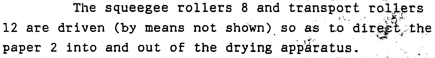
- Squeegee rollers 8 are provided at 'the " entr to the apparatus, the paper 2 entering the apparatus between these rollers.
- the rollers 8 remove surface water which then passes out through a drain outlet 10.
- Transport rollers 12 are provided at the exit from the apparatus. These rollers 12 direct the dried paper 2 on to further processing stages, for example, to cutting apparatus which cuts the paper into individual prints.
- a sensor 14 is positioned halfway along * he path which the paper 2 takes through the drying apparatus, that is between heater stages 4 and 4'.
- the sensor 14 senses the amount of moisture left in the paper 2 as it passes that sensor (after passing through heaters 4).
- the sensor 14 uses a proportional
- the power supplied to the heaters 4' which follow sensor 14 is controlled so as to, in turn, control the amount of further drying that takes place.
- a fan 16 circulates air in the space 40 to provide a small quantity of cooling air for the sensor 14 and the backs of reflectors 18.
- Wire guides 20 are provided to ensure that the paper 2 is transported across the heaters 4, 4 1 to the transport rollers 12.
- a sensor 22 is positioned after the transport rollers 12 so as to provide a final check on the amount of moisture in the paper 2 as it leaves the apparatus.
- FIG. 2 A circuit which may be used to control the apparatus of Figure 1 is shown in Figure 2.
- the circuit comprises a central logic controller 24 which has inputs 26 and 28 from the sensors 14 and 22 (not shown), and outputs 30, 32, 34 and 36 which are connected to the fans 6, fan 16, transport rollers 12 and heaters 4, 4' respectively (also not shown).
- the present invention has the advantage that the power consumption is minimised and the danger of overheating the paper is avoided. Also, the amount of drying is controlled independently of the temperature or humidity of the air being used to dry the material. When the present invention is used in a dryer which operates with infra-red radiation and unheated air, it is very fast. In particular, a high level of power can be applied at the initial stage and then the need for any further drying determined as described above.
- the present invention can be used in processing machines to dry coated exposed and processed material. It can also be used in drying any web or material, for example in coating operations, or in drying chemical solids out of solutions or other materials.
- contact heating using a hot surface can also be employed where appropriate.
- the wire guides 20 in contact with the base of the paper could be heated directly.
- recycled hot air can also be employed.
- Capacitance sensing is- the preferred- arrangement, although contact conductive resistance sensing can also be used.
- the arrangement utilises heating the material from one "side and blowing air from the other side
- any other suitable arrangement could be used as long as the material is heated from at least one side.
- both the heating and the blowing of air could be on the same side of the material.
- the material could be heated from more than one side.
- the air could be blown from more than one side»
- the paper can pass through two heating stages, it is emphasised that any suitable number of heating stages can be employed as desired.
- heating stages being provided by physically successive heaters, they could be provided by the paper being exposed to the same heaters more than once by recycling the paper through the same heaters.
- the arrangement described above has the added advantage that it can be used under any climatic conditions without requiring further adjustment. Naturally, adjustment will need to be made to accommodate materials having different physical characteristics.
Abstract
Description
Claims
Priority Applications (3)
| Application Number | Priority Date | Filing Date | Title |
|---|---|---|---|
| KR1019910700877A KR920701867A (en) | 1989-02-10 | 1990-02-08 | Drying method |
| EP90903027A EP0458825B1 (en) | 1989-02-10 | 1990-02-08 | Apparatus for drying |
| DE69016011T DE69016011T2 (en) | 1989-02-10 | 1990-02-08 | DRYING UNIT. |
Applications Claiming Priority (2)
| Application Number | Priority Date | Filing Date | Title |
|---|---|---|---|
| GB898903064A GB8903064D0 (en) | 1989-02-10 | 1989-02-10 | Drying |
| GB8903064.7 | 1989-02-10 |
Publications (1)
| Publication Number | Publication Date |
|---|---|
| WO1990009621A1 true WO1990009621A1 (en) | 1990-08-23 |
Family
ID=10651502
Family Applications (1)
| Application Number | Title | Priority Date | Filing Date |
|---|---|---|---|
| PCT/GB1990/000191 WO1990009621A1 (en) | 1989-02-10 | 1990-02-08 | Drying |
Country Status (10)
| Country | Link |
|---|---|
| EP (2) | EP0458825B1 (en) |
| JP (1) | JP3107394B2 (en) |
| KR (1) | KR920701867A (en) |
| AT (1) | ATE117102T1 (en) |
| AU (1) | AU5090390A (en) |
| CA (1) | CA2046912A1 (en) |
| DE (1) | DE69016011T2 (en) |
| GB (1) | GB8903064D0 (en) |
| MY (1) | MY106328A (en) |
| WO (1) | WO1990009621A1 (en) |
Cited By (11)
| Publication number | Priority date | Publication date | Assignee | Title |
|---|---|---|---|---|
| US5296873A (en) * | 1992-05-01 | 1994-03-22 | Hewlett-Packard Company | Airflow system for thermal ink-jet printer |
| US5399039A (en) * | 1992-05-01 | 1995-03-21 | Hewlett-Packard Company | Ink-jet printer with precise print zone media control |
| US5406316A (en) * | 1992-05-01 | 1995-04-11 | Hewlett-Packard Company | Airflow system for ink-jet printer |
| US5406321A (en) * | 1993-04-30 | 1995-04-11 | Hewlett-Packard Company | Paper preconditioning heater for ink-jet printer |
| US5428384A (en) * | 1992-05-01 | 1995-06-27 | Hewlett-Packard Company | Heater blower system in a color ink-jet printer |
| US5461408A (en) * | 1993-04-30 | 1995-10-24 | Hewlett-Packard Company | Dual feed paper path for ink-jet printer |
| US5467119A (en) * | 1992-05-01 | 1995-11-14 | Hewlett-Packard Company | Ink-jet printer with print heater having variable heat energy for different media |
| US5479199A (en) * | 1992-05-01 | 1995-12-26 | Hewlett-Packard Company | Print area radiant heater for ink-jet printer |
| US5581289A (en) * | 1993-04-30 | 1996-12-03 | Hewlett-Packard Company | Multi-purpose paper path component for ink-jet printer |
| US5589321A (en) * | 1993-07-20 | 1996-12-31 | Fuji Photo Film Co., Ltd. | Method of and apparatus for controlling drying of photographic material |
| US5774141A (en) * | 1995-10-26 | 1998-06-30 | Hewlett-Packard Company | Carriage-mounted inkjet aerosol reduction system |
Families Citing this family (7)
| Publication number | Priority date | Publication date | Assignee | Title |
|---|---|---|---|---|
| GB2249619A (en) * | 1990-10-11 | 1992-05-13 | Management & Guidance Services | Drying apparatus |
| EP0508254A1 (en) * | 1991-04-12 | 1992-10-14 | Van Brandwijk Systems Programming B.V. | Process and apparatus for heat treatment of a web having a fluid or paste-like composition applied to it |
| DE4206048C1 (en) * | 1992-02-27 | 1993-01-07 | Agfa-Gevaert Ag, 5090 Leverkusen, De | |
| GB9216334D0 (en) * | 1992-07-31 | 1992-09-16 | Kodak Ltd | Film transport means for use in a film dryer |
| US7538299B2 (en) * | 2006-09-27 | 2009-05-26 | Xerox Corporation | Media conditioner module |
| DE102014111807B4 (en) * | 2014-08-19 | 2019-08-22 | Wolfgang Balga | Apparatus and method for processing film |
| CN112540506B (en) * | 2020-11-03 | 2021-12-17 | 李晓光 | Film drying and placing box |
Citations (4)
| Publication number | Priority date | Publication date | Assignee | Title |
|---|---|---|---|---|
| DE1023002B (en) * | 1954-11-20 | 1958-01-23 | Mahlo Heinz Dr Ing | Method and device for regulating drying machines, in particular fabric dryers, for constant moisture content of the draining dry goods |
| US3864843A (en) * | 1972-03-14 | 1975-02-11 | Agfa Gevaert Ag | Apparatus for continuously measuring the surface temperature of moving webs |
| US4142301A (en) * | 1976-10-20 | 1979-03-06 | Ciba-Geigy Ag | Method and apparatus for drying photographic material |
| WO1988008949A1 (en) * | 1987-05-14 | 1988-11-17 | Imatran Voima Oy | Method and apparatus for drying planar material, e.g., veneer sheet |
Family Cites Families (1)
| Publication number | Priority date | Publication date | Assignee | Title |
|---|---|---|---|---|
| JPS5469689A (en) * | 1977-11-15 | 1979-06-04 | Mitsubishi Electric Corp | Mositure rate control system |
-
1989
- 1989-02-10 GB GB898903064A patent/GB8903064D0/en active Pending
-
1990
- 1990-02-08 EP EP90903027A patent/EP0458825B1/en not_active Expired - Lifetime
- 1990-02-08 AT AT90903027T patent/ATE117102T1/en not_active IP Right Cessation
- 1990-02-08 DE DE69016011T patent/DE69016011T2/en not_active Expired - Fee Related
- 1990-02-08 MY MYPI90000207A patent/MY106328A/en unknown
- 1990-02-08 WO PCT/GB1990/000191 patent/WO1990009621A1/en active IP Right Grant
- 1990-02-08 JP JP02503191A patent/JP3107394B2/en not_active Expired - Fee Related
- 1990-02-08 EP EP90301323A patent/EP0383484A1/en active Pending
- 1990-02-08 KR KR1019910700877A patent/KR920701867A/en not_active Application Discontinuation
- 1990-02-08 AU AU50903/90A patent/AU5090390A/en not_active Abandoned
- 1990-02-08 CA CA002046912A patent/CA2046912A1/en not_active Abandoned
Patent Citations (4)
| Publication number | Priority date | Publication date | Assignee | Title |
|---|---|---|---|---|
| DE1023002B (en) * | 1954-11-20 | 1958-01-23 | Mahlo Heinz Dr Ing | Method and device for regulating drying machines, in particular fabric dryers, for constant moisture content of the draining dry goods |
| US3864843A (en) * | 1972-03-14 | 1975-02-11 | Agfa Gevaert Ag | Apparatus for continuously measuring the surface temperature of moving webs |
| US4142301A (en) * | 1976-10-20 | 1979-03-06 | Ciba-Geigy Ag | Method and apparatus for drying photographic material |
| WO1988008949A1 (en) * | 1987-05-14 | 1988-11-17 | Imatran Voima Oy | Method and apparatus for drying planar material, e.g., veneer sheet |
Non-Patent Citations (1)
| Title |
|---|
| PATENT ABSTRACTS OF JAPAN, Vol. 3, No. 93 (M-68), 8 August 1979; & JP-A-5469689 (Mitsubishi Denki K.K.) 4 June 1979 * |
Cited By (13)
| Publication number | Priority date | Publication date | Assignee | Title |
|---|---|---|---|---|
| US5479199A (en) * | 1992-05-01 | 1995-12-26 | Hewlett-Packard Company | Print area radiant heater for ink-jet printer |
| US5399039A (en) * | 1992-05-01 | 1995-03-21 | Hewlett-Packard Company | Ink-jet printer with precise print zone media control |
| US5406316A (en) * | 1992-05-01 | 1995-04-11 | Hewlett-Packard Company | Airflow system for ink-jet printer |
| US5589866A (en) * | 1992-05-01 | 1996-12-31 | Hewlett-Packard Company | Air evacuation system for ink-jet printer |
| US5428384A (en) * | 1992-05-01 | 1995-06-27 | Hewlett-Packard Company | Heater blower system in a color ink-jet printer |
| US5446487A (en) * | 1992-05-01 | 1995-08-29 | Hewlett-Packard Company | Air evacuation system for ink-jet printer |
| US5296873A (en) * | 1992-05-01 | 1994-03-22 | Hewlett-Packard Company | Airflow system for thermal ink-jet printer |
| US5467119A (en) * | 1992-05-01 | 1995-11-14 | Hewlett-Packard Company | Ink-jet printer with print heater having variable heat energy for different media |
| US5461408A (en) * | 1993-04-30 | 1995-10-24 | Hewlett-Packard Company | Dual feed paper path for ink-jet printer |
| US5581289A (en) * | 1993-04-30 | 1996-12-03 | Hewlett-Packard Company | Multi-purpose paper path component for ink-jet printer |
| US5406321A (en) * | 1993-04-30 | 1995-04-11 | Hewlett-Packard Company | Paper preconditioning heater for ink-jet printer |
| US5589321A (en) * | 1993-07-20 | 1996-12-31 | Fuji Photo Film Co., Ltd. | Method of and apparatus for controlling drying of photographic material |
| US5774141A (en) * | 1995-10-26 | 1998-06-30 | Hewlett-Packard Company | Carriage-mounted inkjet aerosol reduction system |
Also Published As
| Publication number | Publication date |
|---|---|
| JP3107394B2 (en) | 2000-11-06 |
| AU5090390A (en) | 1990-09-05 |
| GB8903064D0 (en) | 1989-03-30 |
| EP0383484A1 (en) | 1990-08-22 |
| CA2046912A1 (en) | 1990-08-11 |
| DE69016011T2 (en) | 1995-08-10 |
| JPH04503244A (en) | 1992-06-11 |
| KR920701867A (en) | 1992-08-12 |
| DE69016011D1 (en) | 1995-02-23 |
| MY106328A (en) | 1995-05-30 |
| ATE117102T1 (en) | 1995-01-15 |
| EP0458825B1 (en) | 1995-01-11 |
| EP0458825A1 (en) | 1991-12-04 |
Similar Documents
| Publication | Publication Date | Title |
|---|---|---|
| EP0458825B1 (en) | Apparatus for drying | |
| US5323546A (en) | Method of drying photographic materials | |
| US4017982A (en) | Drying apparatus | |
| EP0606378A1 (en) | Temperature controlled conveyor dryer | |
| US4985720A (en) | Method of controlling temperature for drying photosensitive material | |
| JPS6349760A (en) | Photographic film drying device | |
| JPH08314111A (en) | Apparatus and method for drying of photosensitive material | |
| KR950025152A (en) | Drying device and method of drum washing machine | |
| JP3270564B2 (en) | Photosensitive material processing equipment | |
| JPH01260445A (en) | Drier for photographic film processing machine | |
| JPH04207175A (en) | Drying of laver sheet by automatically detecting dryness of laver sheet | |
| EP0962822A1 (en) | Apparatus and method for drying photosensitive material using a radiant heat section and an air flow section | |
| JPH03131852A (en) | Photosensitive material drying method | |
| JP3645333B2 (en) | Photosensitive material dryer | |
| JPS62242942A (en) | Drying method for photographic film | |
| JPH03252658A (en) | Processing device for photosensitive material | |
| JPH03102348A (en) | Device for processing photosensitive material | |
| DK174802B1 (en) | Dryer for light-sensitive material | |
| JPH08114908A (en) | Drying device for photosensitive material | |
| JPS61117542A (en) | Automatic developing device | |
| JPH01260448A (en) | Drying device for photosensitive material processing machine | |
| JPH03174155A (en) | Processing device for photosensitive material | |
| JPS5912945B2 (en) | Control method for web drying process | |
| JPH0572706A (en) | Drying temperature control method for sensitive material | |
| JP2003005341A (en) | Method and device for driving photosensitive material |
Legal Events
| Date | Code | Title | Description |
|---|---|---|---|
| AK | Designated states |
Kind code of ref document: A1 Designated state(s): AU CA FI JP KR NO US |
|
| AL | Designated countries for regional patents |
Kind code of ref document: A1 Designated state(s): AT BE CH DE DK ES FR GB IT LU NL SE |
|
| WWE | Wipo information: entry into national phase |
Ref document number: 1990903027 Country of ref document: EP |
|
| WWE | Wipo information: entry into national phase |
Ref document number: 2046912 Country of ref document: CA |
|
| WWP | Wipo information: published in national office |
Ref document number: 1990903027 Country of ref document: EP |
|
| WWG | Wipo information: grant in national office |
Ref document number: 1990903027 Country of ref document: EP |