METHODS AND APPARATUS FOR MONITORING
CARDIOVASCULAR REGULATION USING HEART
RATE POWER SPECTRAL ANALYSIS
Background of the Invention The present invention relates in general to methods and apparatus for monitoring cardiovascular regulation and in particular to methods and apparatus for heart rate spectral analysis.
Changes in cardiovascular regulation associated with congestive heart failure include attenuation of activity in the parasympathetic division of the autonomic nervous system, enhancement of activity in the sympathetic division of the autonomic nervous system, cardiac catecholamine depletion, down regulation of the beta-receptor system, increased renin-angiotensin system activity, and alteration of baroreceptor function. All of these regulatory changes require either specific clinical manipulations, such as a stress test, a Valsalva maneuver, or the like, and/or invasive maneuvers, such as cardiac biopsy, plasma catecholamine measurement, or the like, in order to determine the extent of regulatory dysfunction and its impact upon the clinical state of the patient and upon prognoses for the patient. These procedures are time consuming, and generally do not permit the formation of a clinical judgment and subsequent action within the timeframe of the course of treatment for critically ill patients in an Intensive Care Unit.
Fluctuations from heartbeat to heartbeat in measured properties of the circulatory system reflect both the presence of a variety of naturally occurring
physiological disturbances of the circulatory system homeostasis, and the dynamic response of cardiovascular control systems to these disturbances. For example, the cyclic variation in intrathoracic pressure which accompanies breathing mechanically affects the return of venous blood to the heart and also affects blood pressure in pulmonary vessels and in the aorta. The variation in intrathoracic pressure is also coupled to a cyclic variation in heart rate through a neural mechanism mediated by the central nervous system.
Furthermore, the resulting cyclic variation in arterial blood pressure impinges on heart rate through a reflex, known as the baroreceptor reflex, which is mediated by the autonomic nervous system. Disturbances in cardiovascular homeostasis also occur with fluctuations in the resistance of peripheral blood vessels as vascular beds regulate local blood flow to match supply with demand. These fluctuations in peripheral resistance may perturb central blood pressure and, through the baroreceptor reflex, may also lead to a compensatory variation in heart rate.
Many types of medical instruments exist for studying heart rate variability. The instantaneous rate-meter is perhaps the earliest such instrument. This meter measures each RR interval through analog or digital circuitry and displays the instantaneous heart rate.
An improvement in the rate-meter is achieved by performing first order statistical evaluation on the RR-intervals. With mini- and micro-computer systems, histogram displays of RR-interval differences may be generated along with their mean and standard deviations.
Another technique for heart rate variability analysis involves the study of spectral content of the instantaneous heart rate time series. In one approach to spectral analysis in animals, the computations are
done on a computer. Akselrod, et al., Science, 213, 220-222 (1981) Hyndman, et al., Automedica, 1 , 239-252 (1975). Such systems analyze data recorded on magnetic or punched tape. However, not only do these systems introduce additional errors during the recording process, they do not perform in real time. Furthermore, these systems are not multichannel in nature.
A Sparse Discrete Fourier Transform algorithm which may be implemented on a personal computer (CBM 2016) and which may perform on-line monitoring of heart rate variability, based on a low pass filtered cardiac event series is disclosed in Rompelman, et al., IEEE Trans. Biomed. Engineering, BME-29, 503-510 (1982). A specialized hardware device also exists for low pass filtering the cardiac event series by a stepwise. convolution to create the low pass filtered cardiac event series. Coenen, et al., Medical and Biological Engineering and Computing, 15, 423-430 (1977). Nevertheless, these instruments posses a limited band width and a limited frequency resolution capability. There exists a need for an instrument which provides multi-channel spectral analysis of an instantaneous heart rate and of a respiratory activity time series. There also exists a need for an instrument wherein such calculations are performed in real time at the bedside.
Summary of the Invention
An apparatus according to the present invention corrects artifacts in a series of heartbeats. Means for collecting a series of heartbeat samples are coupled to means for determining a mean interval between heartbeats. Means for identifying a mean variance among the intervals between heartbeats samples are coupled to means for establishing an
acceptable of slewing rates as a function of the mean variance. Means for particularizing the absolute value of the slewing rate of a heartbeat sample relative to the mean interval are coupled to the means to determining and means for substituting the mean interval between heartbeats for all heartbeat interval samples having an absolute outside the range of acceptable slewing rates are coupled to the means for particularizing. A method according to the present invention corrects artifacts in a series of heartbeats. A series of heartbeat interval samples is collected and an appropriate interval between heartbeats is determined. Variances in the intervals between heartbeats are identified and an acceptable range of slewing rates is established as a function of a mean variance. An absolute value of the slewing rate of a heartbeat sample relative to the mean interval is particularized. An appropriate interval is substituted for all heartbeat interval samples having an absolute value outside the range of acceptable slewing rates.
Apparatus according to the present invention calibrates a heart rate power spectrum monitor. Means for supplying a signal simulating a heart rate, means for generating a signal simulating a respiratory frequency fluctuation in heart rate and means for providing a signal simulating a low frequency fluctuation in heart rate are coupled to means for applying signals from these means to a heart rate power spectrum analyzer.
Apparatus according to the present invention performs heart rate fluctuation power spectral analysis. Means for providing an electrocardiogram signal and means for supplying electroplethysmogram signal are coupled to means for obtaining a heart rate fluctuation power spectrum from an electrocardiogram
signal and from an electroplethysmogram signal. Real time means for displaying a heart rate fluctuation power spectrum are coupled to the means for obtaining.
Apparatus according to the present invention trends heart rate fluctuation power spectral data.
Means for providing an electrocardiogram signal and the means for supplying an electroplethysmogram signal are coupled to means for obtaining a heart rate fluctuation power spectrum from an electrocardiogram signal and from an electroplethysmogram signal. Means for storing heart rate fluctuation power spectral data are coupled to means for obtaining. Addressable means for transmitting stored heart rate fluctuation power spectral data are coupled to the means for storing and means for converting heart rate fluctuation power spectral data into graphic form are coupled to the addressable means for transmitting. Real time means for displaying heart rate fluctuation power spectra are coupled to the means for converting. A method according to the present invention treats conditions related to malfunctions of the cardiovascular control system. A power spectrum of heart rate fluctuations in the patient are monitored. A level below about 0.1 (beats/min.)2 in the power spectrum of heart rate fluctuations is identified at a frequency between about 0.04 and about 0.10 Hz as indicative of cardiovascular instability. Procedures are applied to treat the condition and thereby to increase the level of heart rate fluctuations at a frequency between about 0.04 and about 0.10 Hz.
A method according to the present invention treats conditions related to malfunctions of the cardiovascular control system in a patient. A power spectrum of heart rate fluctuations is monitored in the patient. A marked increase to above about 10
(beats/min.) in heart rate fluctuations at a frequency
between about 0.04 to about 0.10 Hz is identified as indicative of cardiovascular stress. Procedures are applied to treat the condition and thereby to decrease the level of heart rate fluctuations between about 0.04 and about 0.10 Hz.
Yet another method according to the present invention treats conditions related to malfunctions of the cardiovascular control system in a patient. A power spectrum of heart rate fluctuations in the patient is monitored. A ratio of the area under a heart rate power spectrum peak at a frequency between about 0.04 and 0.10 Hz to the area under a peak in the respiratory power spectrum centered at the mean respiratory rate about 0.1 Hz is identified as having an absolute value less than 2.0 for longer than or equal to about one hour as indicating of cardiac instability. Procedures are applied to treat the condition and thereby to increase the ratio.
Still another method according to the present invention treats conditions related to malfunctions of the cardiovascular control system in a patient. A power spectrum of heart rate fluctuations in the patient is monitored. A ratio of the area under a heart rate power spectrum peak at a frequency between about 0.04 and 0.10 Hz to the area under a peak in the respiratory power spectrum centered at the mean respiratory rate about 0.1 Hz is identified as having an absolute value greater than or about 50 as indicating of cardiac instability. Procedures are applied to treat the condition and thereby to increase the ratio.
Brief Description of the Drawings
Fig. 1 illustrates low frequency, mid-frequency and high frequency in the power spectrum of heart rate fluctuations in a dog according to the
prior art ;
Fig. 2 illustrates aspects of the cardiovascular control system according to the prior art; Fig. 3 is a block diagram of apparatus for heart rate fluctuation power spectral analysis according to the present invention;
Fig. 4 illustrates address buffers and address decoding in a data acquisition device according to the present invention;
Fig. 5 illustrates components according to the present invention for interfacing an ECG apparatus with a personal computer according to the present invention;
Fig. 6 illustrates a digital to analog converter according to the present invention;
Fig. 7 illustrates a ECG trigger according to the present invention;
Fig. 8 illustrates a portable calibrator according to the present invention; Figs. 9A and B are halves of a flow chart for software applicable to an embodiment of the present invention on a IBM personal computer;
Fig. 10 illustrates a trend for a stable patient according to the present invention; Fig. 11 illustrates a trend display for an unstable patient according to the present invention;
Fig. 12 is an illustration of an instantaneous heart rate according to the present invention;
Fig. 13 is an illustration of an instantaneous heart rate fluctuation spectrum of the sort obtainable from apparatus according to the present invention;
Fig. 14 is a stable patient's heart rate fluctuation power spectrum according to the present invention; Fig. 15 is an unstable patient's heart rate fluctuation power spectrum according to the present
invention;
Fig. 16 depicts distributions in LFP data obtained according to the present invention for stable and for unstable patients; Fig. 17 graphically depicts distributions of
RFP data according to the present invention for stable and for unstable patients; and
Fig. 18 graphically depicts data for LFP/RFP ratios according to the present invention for stable and for unstable patients.
Detailed Description
Power spectral methods may be used to analyze the frequency content of fluctuations in heart rate and other hemodynamic parameters. Hyndman, et al.. Nature, 233, 339-341 (1971); Sayers, Ergonomics, 16, 17-32 (1973). Short term (i.e., on a time scale of seconds to minutes) fluctuations in these parameters are concentrated in three principal spectral peaks as illustrated for a canine model in Fig. 1. Akselrod, et al., supra. One peak is centered at the respiratory frequency; this peak shifts with changes in the respiratory rate. The second identifiable spectral peak, the mid-frequency peak, occurs typically between 0.1 and 0.15 Hz. The oscillations associated with this second peak occur at 6-9 cycles per minute, a considerably lower frequency than the respiratory frequency, and are related to the frequency response of the baroreceptor reflex. The third peak of the spectrum typically occurs in the frequency band of 0.04 to 0.10 Hz. This low frequency peak is related to thermoregulatory fluctuations in vasomotor tone.
In one approach to the spectral analysis of heart rate, properties of the heart rate fluctuations in the conscious dog may be related to the activity of
three cardiovascular control systems - the parasympathetic nervous system, the sympathetic nervous system and the renin-angiotensin system. Akselrod, et al., Science, 213, 220-223 (1981). This model is further elaborated in Akselrod, et al., "Hemodynamic Regulation: Investigation by Spectral Analysis " (In Press). Heart rate fluctuations occurring at frequencies above roughly 0.1 Hz are mediated solely by the parasympathetic system. Blockade of the renin-angiotensin system leads to a dramatic increase in the amplitude of the low frequency peak. The effects of an autonomic blockade also exist in humans and changes in body posture alter sympathetic-parasympathetic balance as measured by the heart rate power spectrum. Pomeranz, et al.. Am. J. Physiol., 248, H151-H153 (1985).
A simple model of the short term cardiovascular control system is illustrated in Fig. 2. Akselrod, et al., supra. In this model, heart rate is directly modulated by the sympathetic and parasympathetic nervous systems. Through a variety of receptors both these systems sense, fluctuations in cardiovascular parameters including arterial and venous pressures, vascular volumes, and correlates of blood flow and oxygenation. The parasympathetic system may respond over a wide frequency range while the sympathetic system may only respond at relatively low frequencies below roughly 0.1 Hz.
A hypothesis was proposed in Akselrod, et al., Science, 213, 220-223 (1981), that fluctuations in vasomotor tone associated with the low frequency heart rate fluctuations are not solely related to thermoregulation but also reflect local adjustment to resistance in individual beds of blood vessels in order to match local blood flow to local metabolic demand.
Such fluctuations in peripheral vasomotor tone lead to
fluctuations in central blood pressures which are in turn sensed by pressoreceptors. Stimulation of these pressoreceptors occasions an autonomically mediated baroreceptor reflex, which leads to compensatory fluctuations in heart rate at the corresponding frequency. In addition, the renin-angiotensin hormonal system senses blood pressure fluctuations and, through the elaboration of a substance called angiotensin II, plays the role of the guardian of the overall peripheral vascular resistance. Blockade of the renin-angiotensin system by a converting enzyme inhibitor, may remove this damping influence and may permit increased fluctuations in blood pressure and increased compensatory fluctuations in heart rate in the low frequency regime. The critically ill infant or child prior to, during, and after cardiac surgery at times exhibits marked changes in heart rate, blood pressure, and peripheral perfusion. These changes may be of no clinical consequence or they may indicate the existence of a major unrecognized pathology whose first outward manifestation may be sudden cardiac arrest. To be able to quantify cardiovascular regulatory reserve permits objective assessment of a patient's cardiovascular stability as well as their response to medical and surgical interventions intended to improve cardiovascular function.
Spectral analysis of tape-recorded records of ECG and respiratory activity from patients with complex congenital heart diseases and myocarditis reveals peculiarities in low frequency heart rate fluctuations not seen in studies of healthy children and adults. In particular: (1) low levels of low frequency heart rate fluctuations are noted for critically ill patients in congestive heart failure, which levels revert to normal after surgical or medical treatment and (2) a marked increase in low frequency heart rate fluctuations is
observed in patients with otherwise undetected cardiac tamponade.
A transitional microprocessor-based monitoring instrument, which utilized a Z-80 microprocessor and a S-100 bus, was constructed along with a data acquisition system which interfaced the microprocessor with a Hewlett-Packard 78341 patient monitor.
A prototype system is described in Jerome C. Tu, "Microprocessor System for Real-Time Spectral Analysis Physiological Signals," Master of Department of Electrical Engineering and Computer Sciences, Science Thesis, Massachusetts Institute of Technology (1984). An electrocardiogram (ECG) was inputed into a the data acquisition system from a patient monitor for this prototype system. In the data acquisition system, the analog voltage signal of the ECG was applied to the input of a variable frequency voltage-controlled oscillator in the data acquisition system. A counter coupled to the output of the VCO provided a digital representation of the voltage associated with the ECG peaks. The largest voltage peak, called the R voltage peak and associated in the ECG with ventricular contraction, was used to trigger a clock. Each R peak loaded the value of the clock into a holding register and restarted the clock. The value of the clock provided a measure of the heart rate as the inverse of the time between beats, (i.e., as the RR internal)
The regular respiratory signal of a patient on a ventilator was employed to obtain a respiratory spectrum and was similarly obtained through a VCO The respiratory frequency had to be manually entered in order to establish a fixed window for computing the power in the heart rate power spectrum in the respiratory peak.
Every 256 seconds the digitized ECG RRR
intervals were inputed into the microprocessor from the data acquisition system. A smoothed heart rate "tachometer wave form" was created as follows: (1) the instantaneous heart rate time series was computed from the stored RR intervals; (2) a 1024 point time series of the instantaneous heart rate was computed from the stored instantaneous heart rate time series by sampling the latter at 4 Hz; (3) the mean heart rate computed from the 1024-point time series of instantaneous heart rate was subtracted from the smoothed series resulting in a "tachometer waveform". The heart rate power spectrum was computed from the heart rate "tachometer waveform" as follows: (1) a 1024-Point Fast Fourier Transform was computed using 1024 points of the tachometer cardiac tachometer waveform; and (2) the heart rate power spectrum was computed by squaring the absolute value of the previously calculated transform.
As new data was inputted into the computer's buffer, the results of the smoothed cardiac tachometer signal, power spectrum and integral of power spectrum were outputted onto a printer. Thus, for every 256-second time interval, a spectral representation of the preceding 256 seconds of instantaneous heart rate data was exhibited. From the above data, the area under the low frequency peak (LFP) between 0.04 and 0.1 Hz and the area under the respiratory frequency peak (RFP) within a peak width window of 0.2 Hz were determined. Trend graphs of LFP, RFP, and LFP/RFP ratio were created. The 256 second data segments were rejected if, (1) the patient was not in sinus rhythm; (2) transients and/or artifact were present on the cardiac "tachometer wave form"; and (3) the LFP/RFP ratios were greater than 2 standard deviations from the mean for the study period. The practical problems associated with this prototype monitoring instrument included the extremely
tedious calculations required for use of the prototype with free-breathing patients and the large amount of data (as much as 50%, in some instances) which had to be discarded due to the presence of motion artifacts. These artifacts resulted from virtually any disturbance of the patient, even a disturbance so slight as holding the patient's hand. The prototype system had no capacity to identify or reject artifacts or to examine the data for dropped beats and premature triggers. Upon reviewing clinical studies performed using the prototype, it was discovered that not only were attenuated low frequency heart rate fluctuations associated with a severely compromised regulatory reserve but also that the ratio of the power in the heart rate power spectrum at low frequency to the power at the respiratory frequency provided an even sharper discriminatory index between stable and critically ill patients. In addition it was noted that this ratio was markedly elevated in the setting of moderate to severe congestive heart failure, cardiac tamponade, and prior to the development of malignant ventricular arnythmias.
A low value for LFP/RFP (<2) which is sustained for greater than one hour or a value greater than or about 50 is associated with a clinical course characterized by cardiac arrest and/or profound hypotension. At times this ratio may be the only clinical indicator of cardiovascular instability. The LFP/RFP ratio provides a sensitive and specific index of cardiovascular instability and may provide a clinically important, continuous, non-invasive probe of cardiovascular stability.
In order to further examine the diagnostic value of the power spectrum of heart rate fluctuations and to overcome the difficulties with the prototype, a multipurpose microcomputer-based system, including data basing, instantaneous heart rate and respiratory
activity spectral monitor, was developed using a Hewlett Packard Series 200 Computer and Multiprogrammer as available from Hewlett-Packard. Advantages over the original design include: (1) error correcting routines which correct automatically for motion artifact and missed triggerings of the EKG, thus permitting a substantial increase (>30%) in available data; (2) automated trending of spectral densities along with the instanteous heart rate and respiratory activity time series; and (3) a data basing program which permits accurate temporal correlation of spectral densities with virtually every clinical intervention, routine ventilatory changes, hemodynamic, fluid monitoring and laboratory results. Software incorporating these advantages is included herein as Appendix A.
In a further improvement, programs and a data acquisition system and programs were developed for use with an IBM PC or compatible personal computer. This improvement is illustrated in Figs. 3 through 12. In Fig. 3, a block diagram of apparatus according to the present invention is illustrated. In Fig. 3, a source of an ECG signal 2 and a source of an electroplythsmogram signal 3 are contained within a patient monitor 4. A patient monitor for use with the present invention may be the System 2 Infant Monitor available from ARVEE, Incorporated, Battle Creek, Michigan. Source 2 is connected to an ECG trigger 5 which is in turn connected to a personal computer 7. Source 3 is connected to an analog to digital interface 6. Interface 6 is connected to analog converter 8 which is connected in turn to a personal computer 7. Personal computer 7 receives input from and provides output to interface 6. Personal computer 7 is connected to a display 9. Source 2 receives input from pregelled electrodes adhered to the chest wall and thigh of the
patient. Source senses respiratory activity through a pair of electrodes by the impedence method. Personal computer 7 and display 9 are available as an IBM PC and a compatible display available from IBM, Incorporated, Armonk, New York. Elements 5, 6 and 8 are described below.
In a data acquisition device according to the present invention, address buffers and address decoding, as illustrated in Fig. 4, receive input from a PC bus 10. Nodes 11, 12, 13, 14, 15, 16, 17, 18, 19, 20, 21, 22, 23, 24, 25 and 26 are respectively connected to address lines A0, A1, A2, A3, A4, A5, A6, A7, A8, A9, A10, A11,, A12, A13, A14 and A15 in PC bus 10. A first address buffer 100 has address inputs A0, A1, A2, A3, A4, A5, A6 and A7 which are respectively connected to nodes 11-18. Buffer 100 also has two gate inputs, 1G and' 2G, which are connected to ground along with a ground output GND of buffer 100. A power supply input VCC of buffer 100 is connected to a node 102 at a potential of +5 volts.
A second address buffer 110 has address inputs A8, A9, A10, A11, A12, A13, A14 and A15 which are respectively connected to nodes 19-26. Buffer 110 also has two gate inputs, 1G and 2G, which are connected by way of a node 111 to ground. A ground GND output of buffer 110 is also connected to a common potential. Buffer 110 has a power supply input VCC which is connected to a node 112 at a potential of +5 volts.
A status buffer 120 has address inputs A16, A17, A18 and A19 which are respectively connected to nodes 27, 28, 29 and 30. Nodes 27-30 are respectively connected to an address enable line AEN, a reset line RES, an input/output read line IOR and an input/output write line IOW in PC bus 10. Buffer 120 has two gate inputs, 1G and 2G, which are connected by way of a node 121 to ground. A ground output GND of buffer 120 is
also connected to ground by way of node 121. A power supply input VCC of buffer 120 is connected to a node 122 at a potential of +5 volts.
According to the present invention, a data acquisition system board which is both reliable and compatible with a personal computer (PC) bus, preferably adheres to the timing requirements and the loading requirements supplied by the PC bus. This means that all connections to the PC bus should be buffered so that the load provided at any input or output of the bus is equivalent to 1 LS TTL load and high speed CMOS integrated circuits are provided for this purpose.
Because there are multiple devices attached to the address bus, address buffers are provided. This is done by buffers 100 and 110. Parts used for buffers 100, 110 and 120 are normally gated, but the gate enables, 1G and 2G, are tied to ground so that the gates are always enabled. Some of the status lines on the PC bus are buffered by a chip 120, in particular: the reset line RES; the read and write lines IOR and IOW respectively, for the input/output (10) channels; and the address enable AEN.
An address decoder according to the present invention, as illustrated in Fig. 4, includes a three to eight line decoder 130. Decoder 130 has three line inputs A, B and C which are respectively connected to outputs B2, B3 and B4 of buffer 100. Decoder 130 has gate inputs G2A and G2B which are respectively connected to outputs B5 and B6 of buffer 100. A power supply VCC input of decoder 130 is connected to a node 131 at a potential of +5 volts while a ground GND output of decoder 130 is connected to a common potential. Outputs Y0, Y1, Y2, Y3, Y4, Y5, Y6 and Y7 are connected to inputs, of a NAND gate 140. A NAND gate 151 has an input connected to each of outputs B8, B9 and B10 of buffer 110. An output B100
of buffer 110 is connected to an input of an inverter 152 which has an output connected to an input of NAND gate 151. Similarly, outputs B12, B13, B14 and B15 of buffer 110 are respectively connected to an input of each of inverters 153, 154, 155 and 156, each of which has an output connected to an input of NAND gate 151. NAND gate 151 has an output connected to an input of an inverter 157.
A NAND gate 158 has an input connected to anoutput of inverter 157 and has an output connected to an input of an inverter 159. An inverter 160 has an input connected to an output B7 of buffer 100 and has an output connected to an input of NAND gate 158. Likewise, an inverter 161 has an input connected to an output B16 of buffer 120 and has an output connected to an input of NAND 158. An output of inverter 159 is connected to a gate input Gl of decoder 130.
So that devices on the board are recognized at a particular 10 channel address, address decoding is provided. In this particular case, a fixed address location, location hex 700 to 71F (a total of 32 channels), is used. The decoding of the fixed upper bytes in the address is provided by a combination of nine inverting gates, 152, 153, 154, 155, 156, 157, 159, 160 and 161, and NAND gates 151 and 158. These elements, in combination with decoder 140, provide chip enable signals which can be used to select one or another of the functional chips on our board. Each of the eight chip enable signals correspond to a block of four channels . For example, a chip select #0 from output to of decoder 130 corresponds to channels hex 700, 701, 702 and 703.
A logic network for driving a data buffer, as illustrated in Fig. 5, includes a NAND gate 171, an inverter 172 and a NAND gate 173. An output of inverter 172 is connected to a first input of NAND gate 173 while
an output of NAND gate 140 is connected by way of a node 174 to a second input of NAND 173 and to a first input of a NAND gate 175. A second input of NAND gate 175 is connected to an output of NAND gate 171. In addition, a node 181 is connected to an output BO of buffer 100. A node 182 is connected to an output Bl of buffer 100. Nodes 183 and 184 are respectively connected to output Y0 and output Y7 of decoder 130. Nodes 185 and 186 are respectively connected to an output of NAND gate 175 and an output of NAND gate
173. A node 187 is connected to an output B17 of buffer 120. A node 188 is connected an output B18 of buffer 120, to a first input of NAND gate 171 and to an input of inverter 172. A node 189 is connected to a second input of NAND 171 and to an output B19 of buffer 120. Additional chips are used to provide logic which drives a data buffer connected to a data bus. The data bus is bidirectional in order to both transmit data to and from devices on the board. In order that this be accomplished, one must determine at any time whether or not data is either being read from or written to the board. This logic is supplied by NAND gate 171, NAND gate 173, AND gate 175 and inverter 172 which translates the read and write signals for the input/output (IO) channel into an output enable and a transmit enable for a data buffer. The apparatus of Fig. 4 may be used to properly interface a device to the PC bus 10.
As illustrated in Fig. 5, components according to the present invention for interfacing an ECG apparatus with a personal computer include a port expander 200. Port expander 200 has four sets of 8 nodes each, the four sets correspond to four ports A, B, C and D. The outputs for port A are A0, A1, A2, A3, A4, A5, A6 and A7. The inputs corresponding to port B are B0, B1, B2, B3 , B4, B5, B6 and B7. Outputs corresponding to port C are C0, C1, C2, C3, C4, C5, C6
and C7. A set of outputs corresponding to port D includes D0, D1, D2, D3, D4, D5, D6 and D7. Expander
200 has a chip select input CS connected to node 184. Expander 200 also has a read input RD and a write input WR respectively connected to nodes 188 and 189.
Expander 200 has two address inputs, AD0 and AD1 which are respectively connected to nodes 181 and 182. A reset RES input of expander 200 is connected to node 187. Inputs A0, Al, A2, A3, A4, A5 , A6, A7 are respectively connected to nodes 291, 292, 293, 294, 295, 296, 297 and 298. Outputs D0-D7 are respectively connected to nodes 208, 207, 206, 205, 204, 203, 202 and
201 which define a data bus. A power supply input VCC of expander 200 is connected to a node 209 at a potential of +5 volts. A ground GND output of expander 200 is connected to a common potential.
Port expander 200 is used to overcome the low speed of the data bus on both A/D converter 260 and a digital analog converter. This permits slowing down the read and write signals inasmuch as they may be provided artifically on port C of expander 200 or as chip select signals from address decoder 130. Port C of expander 200 is a bit addressable register which allows one to individually select or deselect bits without affecting any of the other bits. This is accomplished by sending a one byte command to expander 200. Because expander 200 is given the control function, the address of expander 200 is the highest address in the set of channels. In other words, expander 200 occupies 10 channels hex 71C to hex 71F. The ports A, B and C on expander 200 are addresses 71C, 71D and 71E, respectively, and the control register internal for expander is at input/output I/O channel 71F.
A timer 220 according to the present invention has two address inputs, AD0 and AD1 respectively connected to nodes 181 and 182. Timer 220 also has a
read input RD connected to node 188, a write input WR connected to node 189 and a chip select input CS connected to node 184. A first gate input GO is connected to the CO of expander 200 while a second gate input G1 and a third gate input G2 are both connected by way of a node 223 to output C1 of expander 200. Timer 220 has three clock inputs CLK0, CLK1 and CLK2, of which CLK1 is connected by way of node 222 to an output OUT0 of timer 220 and input CLK2 is connected to an output OUT1 of timer 221 by way of a node 31. An interrupt request line IRQ4 within PC bus 10 is also connected to node 31.
An output OUT2 is connected to a non-inverting input of an operational amplifier 224, an inverting input and a output of which are connected to a node 400.
A power supply input VCC of timer 220 is connected to a node 221 which at a potential of +5 volts. Timer 221 has seven outputs D0, D1, D2, D3,
D4, D5, D6 and D7 which are respectively connected to nodes 208, 207, 206, 205, 204, 203, 202 and 201. A ground output of timer 220 is connected to a common potential. Timer 220 includes three 16 bit timers which are addressed at hex locations 704, 705, 706, and 707. In other words, they are provided by chip select 1. The three clocks on timer 220 are connected in series which effectively converts it into a 48 bit counter. However, in the operation of the program, some of the bits in this counter are thrown away because the reset values are less than 65,536. The three clock registers are used in the following way. Counter 0, corresponding to input CLK 0, counts an onboard time base to be discussed later and provides an output which gives the minimum resolution of the heart rate counting. In other words.
it provides the counter time base for measuring the heart rate. Counter #1, corresponding to input CLK 1, counts the heart rate counter time base and provides as an output an interrupt at IRQ4. This signal drives the sampling of the respiratory signal at a constant frequency, and is also used to measure interbeat intervals. In the standard data collecting mode, where one is interested in measuring the respiratory signal at 4 hertz intervals, this means that the counter 0 is set to generate output pulses at 11 microsec. intervals and that these pulses are in turn counted by counter 1 to generate 4 hertz pulses which are used to drive data acquisition from the respiratory signal. The last counter register, counter #2, corresponding to input CLK2, is used to count the number of respiratory sampling pulses which have been supplied. This functions as an overflow counter and always has the reset value of 65,536. Thus the counter measuring interbeat intervals effectively overflows only every 65,536 respiratory sampling times, which is far in excess of what would be required to recover dropped beats which occur because the heart rate is not adequately detected.
A counter 240 has an input 1A connected to a clock line PC CLK in PC bus 10 by way of a node 32.
Counter 240 has a first output IQA connected to the CLKO input of timer 220. Counter 240 has a secnd output 1QB and has a third output 1QC. A clear input CLR1 of counter 240 and a ground output GND of timer 240 are connected to a common potential by way of a node 242.
A data output buffer 280 has an output enable input OE connected to node 185 and has a tranfer enable input TE connected to a node 186. Eight data inputs, A0, A1, A2, A3, A4, A5, A6 and A7, of buffer 280 are respectively connected to nodes 208, 207, 206, 205, 204, 203, 202 and 201. A power supply VCC input of buffer
280 is connected to a source of potential at +5 volts. A ground GND output of buffer 280 is connected to a common potential. Outputs B0, B1, B2, B3, B4, B5, B6 and B7 of buffer 280 are respectively connected to data lines in PC bus 10 by way of nodes 33, 34, 35, 36, 37, 38, 39 and 40.
The time base for this clock system is provided by counter 240. Timer 220 counts only at a rate of 2.6 MHz megahertz which is exceeded by the IBM PC bus clock of 4.77 megahertz. The IBM PC bus clock is divided by 2 using counter 240 and the result used to provide a time base at 2.38 megahertz for timer 220. The 4.77 megahertz clock is also divided by 8 to provide a 596 kilohertz clock which is used to drive an analog to digital (A/D) converter. A/D converter 260 uses this clock signal in order to properly execute the successive approximation scheme to convert analog inputs into digital outputs.
A/D converter 260 has an output enable input OE connected to output C4 of expander 200. A/D converter 260 also has three inputs A, B and C which are respectively connected to outputs C5, C6 and C7 of expander 200. A clock input CLK of A/D converter 260 is connected to the 1QC output of counter 240. An address latch enable ALE and a start input STR of A/D converter 260 are connected to a node 261. A power supply VCC input and a reference voltage +VREF input of A/D converter 260 are connected to a node 262 at a potential of +5 volts. A reference voltage -VREF output and a ground GND output of A/D. converter 260 are connected to a common potential by way of a node 263. A/D converter 260 has seven outputs D0, D1, D2, D3, D4, D5, D6 and D7 which are respectively connected to inputs B0, B1, B2, B3, B4, B5, B6 and B7 of expander 200. In addition, A/D converter 260 has an end of count EOC output connected to a first input of the NAND gate 264, an output of
which is connected to an input of an inverter 265. A second input of NAND gate 264 is connected to an output of an inverter 266 which has an input connected to node 187. An output of inverter 265 is connected to node 261.
A/D converter 260 has a signal input IN connected to a node 267. An output of an operational amplifier 268 is connected to node 267 and to a first lead of a resistor 269. A second lead of resistor 269 is connected to a first lead of resistor 270, a second lead of which is connected to a source of potential at -5 volts. The first end of resistor 270 is also connected to an inverting input of amplifier 268 and to a first end of a resistor 271. A non-inverting input of amplifier 268 is tied to ground. A second end of resistor 271 is connected to a node 272 which provides an analog signal input ANA IN for the apparatus according to the present invention.
A/D converter 260 is connected to port B of port expander 200. This A/D has built into it its own 8 channel analog multiplexer which allows the selection of one of eight analog signals to be converted. The channel select corresponding to inputs A. B and C of converter 260 is connected to port C on bytes 5, 6 and 7.
Because A/D converter 260 operates from 0 to 5 volts, analog input at input IN should be in the range of 0 to 5 volts or an input buffer should be supplied to alter this input range. However, in keeping with general practices for safety and isolation, input IN should always be provided with an analog buffer to provide isolation for both the computer and the instrument being monitored. As illustrated, the input buffer is provided by operational amplifier 268. This amplifier converts a bipolar analog input of plus or minus 5 volts to a single unipolar input of 0 to 5 volts
at input IN. This analog input is used to monitor the respiration.
A/D converter 260 is set up in a free running mode such that it continuously does conversions on the analog signal. The end-of-conversion pulse at output EOC is used to generate a start pulse for the A/D so that as soon as an end of conversion occurs it a new conversion is started. This is the reason for the two gates connected between end of conversion output EOC and the start input STR. In order to prevent latchup of the device on power up, the reset line at node 187 is also used to generate a start pulse. This means that the device will always function even after being powered up. Also, in order to update A/D converter 260 as frequently as possible, the address latch enable ALE, which is used to latch in the address value for the channel to be monitored, is re-latched at every start pulse.
As illustrated in Fig. 6, digital analog (D/A) converter 300 has inputs D0, D1, D2, D3, D4, D5, D6 and D7 which are respectively connected to nodes 298, 297, 296, 295, 294, 293, 292 and 291 as illustrated in Fig. 5. Converter 300 has a write WR input connected to node 183 and has a feedback input RFB. Converter 300 also has a power supply VCC input, a reference voltage VREF input and an input latch enable input ILE all of which are connected to a source of potential at +5 volts by way of a node 301. Converter 300 has an analog ground AGND and a digital ground output DGND, both of which are connected by way of a node 302 to a common potential. Converter 300 has a first output OUT1 and a second output OUT2 which are respectively connected to an inverting and a non-inverting input of an operational amplifier 303. The non-inverting input of amplifier 303 is also connected to a common potential by way of a node 305. .Amplifier 303 has an input connected to a node 306
at a potential of +12 volts and an input connected to a node 307 at a potential of -12 volts. An output of amplifier 303 is connected to a node 308 which is connected to the RFB input of converter 300 and to a first end of a variable resistor 309. A second lead of variable resistor 309 is connected to a first lead of a variable resistor 310, a second lead of which is connected to a node 311 at a potential of +5 volts. The second lead of resistor 309 is also connected to an inverting input of operational amplifier 312 and to a first lead of a resistor 313. A non-inverting input of amplifier 312 is connected to ground. A second lead of resistor 313 is connected to an output of amplifier 312 and to a node 391 which serves as an analog output for the apparatus according to the present invention.
Port A of expander which is at location 71C, is attached to a D/A converter data bus which, includes nodes 291-298. The write latch signal for the D/A converter is provided by chip select #0. In other words, any dummy byte written to any of the addresses
700, 701, 702 or 703 hex will cause a write pulse to be sent to D/A converter 300, thereby latching the data on port A of expander 200 into the D/A converter 300 and allowing an analog signal to be generated corresponding to the digital input. The output of D/A converter 300 chip is in the form of differential currents generated at outputs OUT 1 and OUT 2. A system having two operational amplifiers is employed to convert these currents to a voltage. Amplifier 303 is a differential current to voltage converter which provides a signal from 0 to 5 volts. Amplifier 312 converts the signal to a bipolar plus or minus 5 volt signal. Feedback control for the current to voltage converter is provided in D/A converter 300 through input RFB so that in actuality three connections are made from the D/A chip to the first operational amplifier. Because the D/A converter
is an 8 bit device, this provides 256 voltage levels which are linearly distributed between plus and minus 5 volts. This D/A output may be used to generate calibrating signals or other control signals. As illustrated in Fig. 7, a source of an ECG signal is connected by way of a node 400 to a non-inverting input of an operational amplifier 401 in an ECG trigger 60. An input of amplifier 401 is connected to a node 402 at a potential of plus 12 volts. An inverting input of amplifier 401 is connected to an output of amplifier 401 and to a non-inverting input of an operational amplifier 406. A first lead of each of resistors 403a, 403b, 403c, 403d, 403e, 403f, 403g, 403h and 403i is connected to the output of amplifier 401 while the second lead of resistor 403i is permanently connected and a second lead of one other of resistors 403a through h is connected to a node 410 by a jumper. A first lead of capacitor 404 is connected to node 410 while a second lead of capacitor 404 is connected to a node 405 at a potential of minus 12 volts. An inverting input of amplifier 406 is connected to a cathode of a diode 407, an anode of which is connected to an output of amplifier 406. The cathode of diode 407 is also connected to a first lead of capacitor 408 and a first lead of each of resistors 410a, 410b,
410c, 410d and 410e, the second lead of resistor 410e is permanently connected and the second lead of one other of which is connected to a node 410 (not shown) by a jumper 411g (not shown). A non-inverting input of an operational amplifier 412 is also connected to the cathode of diode 407 while an inverting input of amplifier 412 is connected to the output of amplifier 406. An input of amplifier 412 is connected to a node 413 at a potential of minus 12 volts. A first lead of resistor 414 is connected to the output of amplifier 412 while a second lead of resistor 414 is connected to a
cathode of a diode 415 an anode of which is connected to ground. The cathode of diode 415 is also connected to an input of a Schmitt trigger 416 an output of which is connected to a line designated IRQ 3 in PC bus 10 by way of a node 491.
ECG trigger 60 has an input buffer consisting of a non-inverting buffer of an amplifier 401 which isolates the ECG signal from the rest of the board. As illustrated in Fig. 5, the EKG trigger functions in the following manner. The R wave, which is larger than any other signal in the ECG, causes capacitor 408 to charge up to a certain value corresponding to the peak of the R wave. Any values beneath the peak of the R wave will be rejected by amplifier 403 so that no output occurs. Between R waves, the voltage on capacitor 405 decays slowly with a rate given by the RC time constant of capacitor 405 and the resistance across elements 410a- f. The voltage on the capacitor is sent to the inverting input on amplifier 403 and is used as a threshold for the R wave of the EKG. Therefore, as the electrocardiogram is being passed to the non-inverting input of amplifier 406, the only time that the operational amplifier has a positive output is when the EKG signal is larger than the voltage on capacitor 405. Whenever this occurs, capacitor 408 is immediately charged up to the value at the EKG input. In other words, the voltage on capacitor 408 is a sort of envelope on the top of the electrocardiogram, although its decay rate is limited by the RC time constant. Diode 407 insures that the envelope function which is provided by capacitor 408 is the upper envelope and not the lower envelope. The lower envelope is provided by reversing the polarity of diode 407.
The RC network of capacitor 405 and resistors 403a-i provides a low pass filtered ECG. The voltage on capacitor 405 is the baseline for the ECG, which may
vary. The array of jumper selected resistors 410a-e allows variation of the time constant of the RC network containing resistors 406a-e and capacitor 408. Thus, this latter network which monitors the ECG envelope is referenced to the ECG baseline present on capacitor 404 permitting accurate tracking of the envelope and therefore better R wave detection. As a further improvement, the jumpers may be replaced with analog switches controlled by the personal computer in order to give the computer control of RC time constant selection. An output from ECG trigger 60 is generated by connecting amplifier 412 in parallel with peak detector amplifier 406 so that the inputs are reversed. The result is that the output polarity is inverted. Because the amplifiers 401, 406 and 412 are operating from a plus 12 volts to minus 12 volts supply, but the logic levels on the board are only from 0-5 volts, resistor 414 and a diode 415 are used to clamp the output value of the amplifier 412 between 0 and 12 volts. This signal is then passed to a Schmitt trigger 416, which is a single conditioning device. The output of this signal conditioner is finally provided to PC bus 10 in order to drive interrupts at interrupt request 3 (IRQ3) indicating the currents of an R wave. ECG trigger 60 may be modified to allow selection of various decay rates for the envelope and also to provide a floating threshold for the 0 point of the EKG. The ECG triggers if the R wave passes above 0 volts. However, it can be imagined that sometimes the baseline will drift far enough below 0 volts that the R wave does not cross 0 volts and in such a case this trigger would never detect the R wave. This is corrected by connecting the second leads of the charging capacitor 408 and On the selected discharging resistor of 406a-f may be connected to a low pass filter consisting of a capacitor 405 and a selected one of resistors 403a-f (to choose various discharge
rates) which low pass filters the electrocardiograms and essentially selects out the baseline. This means that instead of measuring the R wave with respect to 0 volts, the R wave may be measured with respect to the floating baseline of the electrocardiogram. The jumper selected resistor selects an RC time constant much greater than the RR interval. So long as the baseline does not drift faster than one R wave in approximately 10 heart beats, this means that this trigger will successfully detect all R waves. Selecting one of resistors 410a-f allows variation of the RC time constant of elements 408 and 410a-f.
As illustrated in Fig. 8, in a portable calibrator 70 according to the present invention, an operational amplifier 500 has a non-inverting input connected to a first lead of each of resistors 501, 502 and 503. A second lead of resistor 501 is connected by way of a node 503a to a positive voltage source while a second lead of resistor 502 is connected by way of a node 504 to a negative voltage source. An inverting input of amplifier 500 is connected to a first lead of a capacitor 505, a second lead of which is connected by way of a node 506 to a negative voltage source. The inverting input of amplifier 505 is also connected to a first lead of a variable resistor 507 and to a first lead of a resistor 508 a second lead of which is connected to an output of amplifier 500. The output of amplifier 500 is also connected to a second lead of resistor 503. Amplifier 500 has an input connected by way of a node 509 to a positive voltage source and by way of a node 510 to a negative voltage source.
A second lead of resistor 507 is connected to a non-inverting input of an amplifier 511, an inverting input of which is connected to an output of amplifier 511 by way of a node 591 which provides an output port for a simulated respiratory frequency.
A first lead of a resistor 512 is connected to node 591 while a second lead of resistor 512 is connected to a first lead of a resistor 513 and to a first lead of a capacitor 514, a second lead of which is connected by way of a node 515 to a negative voltage source. A second lead of resistor 513 is connected to an output of an operational amplifier 514 and to an inverting input of amplifier 515 is connected to a first lead of a resistor 516, to a first lead of a capacitor 517 and to an inverting input of an operational amplifier 518. The second lead of capacitor 517 is connected by way of a node 519 to a negative voltage source. A non-inverting input of amplifier 518 is connected to a first lead of each of resistors 520, 521 and 522. A second lead of resistor 520 is connected by way of a node 523 to a positive voltage source while a second lead of resistor 521 is connected by way of a node 524 to a negative voltage source. A second lead of resistor 522 is connected to an output of amplifier 518 and to a second lead of resistor 516.
An inverting input of an operational amplifier 525 is connected to the first lead of resistor 513 and to a first lead of a variable resistor 526. A non-inverting input of amplifier 525 is connected to a first lead of each of resistors 527, 528 and 529. A second lead of resistor 527 is connected to a node 530 at a positive potential while a second lead of resistor 528 is connected by way of a node 531 to a negative voltage source. A second lead of resistor 529 is connected to a second lead of resistor 526 and to an output of amplifier 525 at a node 592 which provides a square wave output simulating a modulated heart rate pulse. A first lead of a capacitor 532 is connected to node 592 while a second lead of capacitor 532 is connected by way of a node 593 to a first lead of a resistor 533, a second lead of which is connected to
ground. Node 593 provides an output port for a spike output simulating the R wave of an EKG.
The source of positive potential for the portable calibrator 70 may be at a voltage between about plus 5 and about plus 18 volts. Similarly, the negative voltage source for portable calibrator 70 may be at a potential of about minus 18 volts to about minus 5 volts.
Portable calibrator 70 provides test signal for the heart rate spectral analysis hardware which, although not of a truly calibrated nature, does allow one to evaluate whether or not the software and hardware is functional. Each of the output signals provided is a triangle wave which represents the respiration and a frequency modulated pulse train representing the heart rate. The modulation of the heart rate is provided at two frequencies which simulate a respiratory modulation and also a low frequency modulation.
The basic circuit of calibrator 70 for providing each pulse train consists of an oscillator having one operational amplifier as typified by the respiratory frequency modulator. A charging capacitor 505 and a variable resistor 507, provide an RC circuit which is charged by the output of the amplifier 500. It is also discharged by the amplifier 500 when the output of the amplifier 500 is low. Progressive cycles of the oscillator consist of charging and discharging the capacitor at the rate prescribed by the RC circuit. The reference level which determines whether or not one is discharging or charging is provided at the non-inverting input of the amplifier 500.
Suppose, for example, that capacitor 505 begins as being completely discharged, then the voltage at the inverting input for the operational amplifier 500 is low. The output of the operational amplifier 500 is therefore high and this means that the input at the
non-inverting input is 2/3 the voltage between the negative voltage source V and the positive voltage source V+. Thus the capacitor 505 begins to charge. When the capacitor voltage exceeds the threshold at the non-inverting input of the operational amplifier 500, the output of operational amplifier 500 changes sign and capacitor 505 begins to discharge. However, when the output of the amplifier 500 changes to the negative side, then the threshold voltage at the non-inverting input is changed and now.becomes only 1/3 the way from the negative voltage source to the positive voltage source. This means that the voltage on the charging capacitor 505 varies between 1/3 and 2/3 the difference between the negative and the positive voltage source. This determines the range of output on capacitor 505. The voltage at capacitor 505 is buffered by a non-inverting buffer 511 and this provides the respiratory signal at node 591.
An identical oscillator is used to provide low frequency modulation. The difference in the two frequencies is obtained by adjusting the respective variable resistors, 505 and 517,which set the RC time constants. The outputs of these two modulators are fed by resistors 512 and 513 into the charging capacitor 514 for the heart rate.
The heart rate oscillator is similar in design and consists of variable resistor 526 and capacitor 532 which charges and discharges in cycles with the range of voltages on the capacitor ranging between 1/3 the distance from the negative voltage source to the positive voltage source to 2/3 the voltage between the negative voltage source and the positive voltage source. Resistors 512 and 513, which connect the outputs of the low frequency and respiratory frequency modulators to the heart rate modulator, allow a small amount of current to flow into charging capacitor 514 of
the heart rate modulator. This alters the charging rate of capacitor 514 and thereby affects the rate at which the heart rate oscillator oscillates. For example, on a positive cycle of the respiratory frequency modulator, the heart rate capacitor is charging more rapidly towards the plus side because more current is being supplied on the plus side of the cycle. Finally, the output of the heart rate modulator is sent through an RC filter comprising capacitor 532 and resistor 533 which converts the square wave output of the heart rate modulator into a spike output which may be sent to an R wave detector. Notice that the spike output includes both positive and negative spikes so that an R detector which depends on a high frequency filtering function may be discharging at twice the heart rate, inasmuch as it may trigger on both positive and negative spikes.
As illustrated by a block diagram in Figs. 9A and 9B, a block diagram may be constructed for the main program (designated SYNCTS19) and for sub-routine modules (SYNC7s, GWINDOW3, and FGRAPH8 ) . This block diagram may be used in order to better interpret a complete program for heart rate fluctuation spectral analysis useful on an IBM personal computer, as illustrated in Appendix B. Although programs are provided for a Hewlett-Packard and an IBM computer herein, the software and other aspects of the present invention may be readily modified for use with other mini- and micro-computers.
In the program of Appendix B, is a routine for removing artifacts from a detected heart rate provided for by an electrocardiograph machine. This program computes histograms from the heart rate data in order to generate a tachometer waveform. The most common rate on the histogram is selected as the correct rate and other rates are interpreted in light of it. Specifically, in order to correct for a spurious extra trigger, where a
first and a second beat are close together while a third beat is spaced at an abnormally long interval, the second beat is discarded if the first beat to second beat interval is less than a predetermined value. The resulting interval between the first and the third beats is divided by an integer in order to provide a more normal intrabeat interval. Where a trigger has been missed, so that a first and a second beat are separated by an interval which is approximately a multiple of a normal intrabeat interval, the intrabeat interval is divided by that multiple, most commonly two, in order to provide a more correct interval length. If the slewing rate of the heartbeat samples is outside of an acceptable range of slewing rates determined as a function of a mean variance, and the problem cannot be identified as a missed trigger or as a spurious extra trigger, or if the three previous intervals have been corrected, a determined mean interval, against which all other intervals are judged, is substituted for the inappropriate interval.
The slew rate is calculated on a moving average of the heart rate waveform and corrects for triggers that fall within the parameters of 0.05 Hz (3 beats/min.) per beat and five times the maximum slew. This artifact-correcting routine never slews more than 10 percent of the heart rate waveform.
Within the software of Appendix A is a graphic routine for trending heart rate fluctuation spectral data. The parameters of LFP, RFP, LFP/RFP ratio and heart rate are plotted on a graph over time to show trends in the four parameters. These trends may then be studied in order to examine the effects of various clinical interventions. Values for the parameters heart rate, LFP/RFP ratio, LFP and RFP are stored and may be called up at any point in time through a graphin routine in order to provide a graphic depiction of the
course of a patient's condition. This sort of graphic depiction is illustrated for a stable patient in Fig. 10 and for an unstable patient in Fig. 11.
Also present in the program of Appendix B, a routine is provided for the segmentation of data and subsequent reanalysis. In this routine, data from the analog to digital converter 260 is collected continuously into a buffer and is dumped to a disk in blocks of 1,024 numbers (2,048 bytes equals 1,024 words and each block is referred to as a record or EPOCH). The time of heartbeat occurrence as measured by the signal provided by outputs OUT1 and OUT2 of timer 220 are collected continuously into two buffers (hb buffer 1 and hb buffer 2). These times are dumped to the disk in blocks of 1,024 pairs of numbers (1,024 from each buffer which equals 2,048 bytes or 1,024 words each). Because the heart rate is less than the sample rate of A/D converter 260 as required by signal processing, there are fewer heartbeat disk dumps. In order to properly analyze data, the A/D and heartbeat data must correspond to the same time interval for the purpose of doing correlations. The correspondence may be determined from (1) the record number in a A/D file and (2) the absolute of the times stored in the heartbeat file (time differences used for intrabeat intervals). The instantaneous heart rate signal is generated backwards in time from the heartbeat corresponding to the last A/D sample in the record of interest. This means that if the heart rate signal is analyzed on a frequency scale not corresponding to the respiration data (e.g. respiration sample at 16 Hz but a heart rate analysis at 0 to 4 Hz) then the heart rate waveform extends backwards in time beyond the beginning of the present A/D record. This means that the heart rate waveform overlaps the heart rate waveform corresponding to the previous A/D records.
Overlapping permits lower frequency analysis than would be possible if only data corresponding to the present record were used (as in the prototype apparatus). Also, overlapping leads to the smoothing of parameters and to the subsequent reduction of fluctuating artifacts. In addition, it becomes less critical at what point analysis begins.
A calibration program providing a software driven calibrator, which may provide more realistic spectral data than the portable calibrator of Fig. 8, is contained within the program of Appendix A for a Hewlett-Packard micro-computer. Appendix C is a program which, although not tested, is believed to provide the same sort of software-driven calibration for an IBM personal computer through the data acquisition system of Figs. 4 through 7.
In general, outputs OUT0 and OUT1 of timer 220 in Fig. 5 generate a time base used via interrupt request line IRQ4 to clock data from a buffer.to D/A converter 300. This buffer contains a respiratory waveform which may be a sign wave or any selected waveform as obtained by changing the contents of the buffer. Output OUT2 of timer 220 generates a heartbeat pulse as its output. In order to work properly, this pulse must be returned to the ECG trigger through node 400 or directly to interrupt request line IRQ3. If the latter course is chosen, however, node 491 must be disconnected from the output of Schmitt trigger 416. By returning the pulse to the ECG trigger, the computer is informed that the timer is through counting the present RR interval and needs a new interval to be loaded into a timer register of timer 220.
Through the use of the apparatus according to the present invention, a display of instantaneous heart rate as provided by an electrocardiograph machine, and as illustrated in Fig. 12, may be converted into an
instantaneous heart rate fluctuation spectrum as illustrated in Fig. 14. A typical spectrum for a stable patient is illustrated in Fig. 14 while a typical spectrum for an unstable patient is illustrated in Fig. 15.
Example I and Example II relate respectively to diagnosis and to treatment employing the present invention.
Parts suitable for use in construction of the apparatus as illustrated in Figs. 4 through 9 may include those as listed in Tables I, II, III and IV.
EXAMPLE 1
Heart rate spectral analysis was applied to the study of congestive heart failure in infants and children. Congestive heart failure is characterized by a marked alteration in cardiovascular regulation. However, many cardiovascular functions which are normally monitored in cardiac intensive care units (such as: mean heart rate; arterial blood pressure; arterial blood gases; left arterial pressure and right arterial pressure; right atrial, left atrial and pulmonary artery oxygen saturations; the peripheral pulses; peripheral perfusion; and cardiac output) may not clearly indicate a critically unstable cardiovascular condition. The usually-monitored cardiovascular function parameters may be within a normal range immediately before a major cardiovascular crisis, such as hypotension or cardiac arrest, inasmuch as the cardiovascular regulatory system maintains these parameters within a normal range up to the point of system failure.
Twenty-nine infants and children were studied in a cardiac intensive unit. Of the twenty-nine patients, twenty-six have undergone a cardiac surgical
procedure. The patients were studied for a minimum of three hours and a maximum of twenty-seven hours, with a mean study time of eight hours. EKG for cases were recorded and analyzed continuously in real time during the study time.
Data for a particular patient was analyzed only if the patient was in sinus rhythym. The patient's clinical course during the period of study was reviewed and, in particular, major events such as cardiac arrest, hemorrhage and profound hypotension were correlated with spectral analysis data. Administration of medication and the mode of ventilation were noted.
Real time heart rate spectral analysis was performed on a dedicated personal computer using a 6809E Motorola Microprocessor-Based System. A data acquisition system interfaced the computer with a patient monitor, available from Hewlett-Packard, Palo Alto, California, as Model No. 78341.
The heart rate power spectrum was calculated in continuous 256 second data epochs. A QRS synchronization pulse from the patient monitor was used to determine an RR interval sequence. An instantaneous heart rate signal was computed from RR interval sequence and the magnitude of the signal was set to the reciprocal of the current interbeat interval. The instantaneous heart rate signal was sampled at 4 Hz and the mean heart rate was substracted from the resulting one thousand twenty-four point time series. A power spectrum was computed by squaring the absolute value of a Fast Fourier Transform of the one thousand twenty-four point time series. Values for low frequency power (LFP) were computed by integrating the spectrum of between 0.04 and 0.1 Hz. Respiratory frequency power (RFP) was computed by integrating the heart rate power spectrum over a 0.2 Hz-wide band centered at the mean respiratory frequency.
Hard copies of the heart rate time series and power spectrum were printed for each 256 second epochs. Trend graphics for the LFP, the RFP, LFP/RFP ratio, mean heart rate and respiratory rate (hereinafter referred to as the study parameters) were constructed by manually entering data in data files and analyzing the entered data by means of a computer.
Mean values for the study parameters were calculated for each period of study. The Mann-Whitney Rank Sum Test was used to determine statistically •significant changes in the study parameters in individual patients and to determine differences among groups of patients. When patients were segregated into more than two groups, the Kruskal-Wallis Test, multiple comparison test, and Tukey's HSD were employed to determine statistical significance. P values of less than 0.05 were considered significant..
It was found that during each three to twenty-four hour period of study the study parameters for a given patient, the LFP, the RFP and the LFP/RFP ratio (hereinafter referred to as the spectral parameters) remain fairly stable.
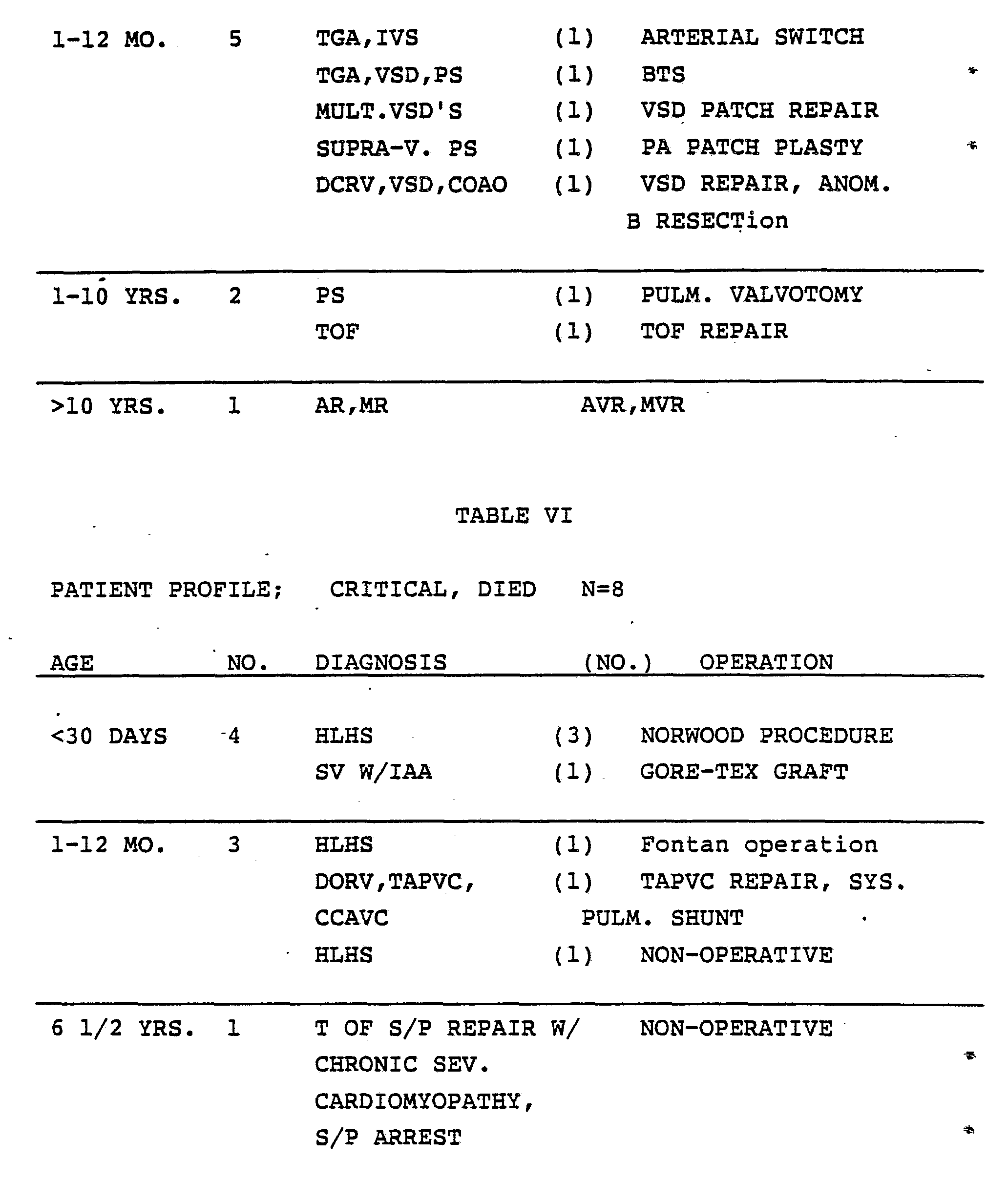
Based upon the results of this study, the patients were retrospectively divided into three groups. Group I included seventeen stable patients whose median age was one month. The patients in Group I were without major post-operative complications and did not need prolonged inotropic support. The eight patients in Group II suffered cardiac arrest and died. The median age for the members of Group II was one month. In Group III, there was a total of four patients each of whom was critically ill at the time of the study but later recovered. Median age of the members of Group III was one month. Of the four members of Group III, one required re-operation, one had intermittent hypotensive episodes, and two had cardiac arrests from
which they were successfully resuscitated.
In order to separate all twenty-nine patients into a group of stable patients (Group A) and a group of critical patients (Group B), data from each patient in Group III was divided into the data collected during the stable period (which applied to three patients) and the data collected during the preceding critical period (which applied to four patients). When handled in this way. Group A included data for twenty patients and Group B included data for twelve patients. Typical heartrate fluctuation power spectra for Group A and B are respectively illustrated in Figs. 16 and 17.
In addition, studies were performed on three patients who had isolated coarctation of the aorta at three points in time: upon admission for congestive heart failure; during treatment; during post-operative period; and prior to discharge from an intensive care unit. An attempt was made to identify changes in cardiovascular regulatory function of each of these stages.
Patient profiles for Groups I, II and III are respectively provided in Tables V, VI and VII. These profiles include age, diagnosis and operation.
In Tables V, VI and VII: TGA is Transposition of the Great Arteries; IVS is Ventricular Septal Defect; PS is Pulmonic Stenosis; HLHS is Hypoplastic Left Heart Syndrome; SV is Single Ventricle; SEV. is severe; COAO is Coarctation of the Aorta; MULT is multiple; VSD is Ventricular Septal Defect; Supra-V. is Supravalulvar; DCRV is Double Chamber Right Ventricle; TOF is Tetralogy of Fallot; AR is Aortic Regurgitation; MR is Mitral
Regurgitation; W/IAA is with Interrupted Aortic Arch; DORV is Double Outlet Right Ventricle; TAPVC is Total Anomalous Pulmonary Venous Connections; CCAVC is Complete Common Atrial Ventricular Canal; S/P is Status Post; L is Left; BTS is Blailock Taussig Shunt; PA is Pulmonary Artery; ANOM. is Anomalous; B is muscle Bundle; PULM is Pulmonary; and SYS is Systemic.
Statistically significant differences were observed in the heart rates spectral parameters between the groups of patients as well as among the individual patients. However, the mean heart rate alone did not distinguish stable from critically ill patients. Both the LFP and the LFP/RFP ratio discriminated between the Group A (stable) patients and the Group B (critical) patients. The LFP/RFP ratio grew out of a statistically significant (p less than symbol 0.00001) discrimination
between stable and critical patients, Table VIII presents means of study parameters.
The discriminate value for the LFP/RFP ratio was two. In Group A, the range of LFP/RFP ratios was 3 to 22 (arithmetic mean 8.77). The range of RFPs was 0.01 to 3.13 (arithmetic mean 0.28) and the range of LFPs was 0.09 to 13.88 (arithmetic mean 1.77). In Group
B, the range of LFP/RFP ratios was 0.17 to 1.9 (arithmetic mean 0.83), the ratio of RFPs was 0.02 to 0.32 (arithmetic mean 0.1), and the range of LFPs was 0.01 to 0.1 (arithmetic mean 0.5) Although the mean value of the LFP/RFP ratio was greater than two for Group I, the ratio for the stable patients fell below two for brief periods. That which distinguishes the stable from the critical patients is the sustained value for greater than or about one hour of the LFP/RFP ratio for the critical group.
The results are graphically depicted in Figs. 19, 17 and 18. In Figs. 16 and 17, each heavy dot A represents a geometric mean, each light line B indicates the standard error of the geometric mean and each heavy line C represents the standard deviation of the geometric mean. In Fig. 18, each heavy dot A represents an arithmetic mean, each set of slashes B1 and B2 represents the standard error of the arithmetic mean and each set of slashes C1 and C2 represents the standard deviation of the arithemetic mean.
The significance of heart rate spectral analysis for diagnosis of cardiovascular stress and the prediction of fatality is highlighted by the fact that patients with a low LFP/RFP ratio underwent a cardiac arrest even in the presence of otherwise normal vital signs. No patient with a LFP/RFP ratio greater than two experienced a cardiac arrest.
Infusion of pressors, alone or in combination with vasodilators, did not induce a low LFP/RFP ratio. Four patients in Group III had LFP/RFP ratios less than two during their critical periods. For the three of these four patients who were restudied during their recovery periods, all three had LFP/RFP ratios greater than two.
The mean LFP for Group B [0.05 (Beats per
minute)2] was less than the mean LFP for Group A [1.77 beats per minute)2], p <0.0001. There was no significant difference between the mean RFP between the groups. The initial LFP/RFP ratios for the patients with isolated coarctation of the aorta ranged up to 10,000. The LFP/RFP ratios observed for this group immediately after an operation to correct the condition were within the range for Group A patients. Two patients had LFP/RFP ratios greater than 100 before discharge from the intensive care unit. These ratios were correlated with mild to moderate congestive heart failure. One of these patients died suddenly at approximately 2-1/2 months after the operation. The other two patients remained alive and well.
Although the LFP/RFP ratio provided the sharpest discrimination between stable and critical patients in these studies, the LFP alone discriminated between Groups A and B, p <0.0001. Neither respiratory frequency peak power nor mean heart rate distinguished between Groups A and B. On the other hand, LFP/RFP ratios and LFP levels low levels sustained for greater than or about one hour correlate with the course of the conditions of patients who experienced cardiac arrest or severe hypotensive episodes but later recovered.
Although stable patients experienced transient depression of levels of LFP and of the LFP/RFP ratio, depression of these factors for about an hour or more never failed to predict a critical status. No significant difference was observed between freely ventilating patients and mechanically ventilated patients. Eighteen out the twenty patients in Group A were mechanically ventilated and all twelve of the Group B patients were mechanically ventilated. All patients in Group B received inotropic support while more than half of the patients in the
Group A received at least some inotropic support. The cardiac diagnoses of all of the patients in Group B and for some of the patients in Group A were known to be associated with high mortality. All of the patients in Group B underwent deep hypothermic circulatory arrest during their operations. Of the twenty patients in Group A, nine had extra cardiac surgery (i.e. not involving cardiopulmonary bypass or deep hypothermic circulatory arrest). Three of the patients in Group II did not undergo operations. Therefore, it is not believed that differences in treatment or disease specific pathology alone explained the low values LFP and the low LFP/RFP ratios in Group B patients but that the low values actually reflect a vulnerable circulatory state.
It has also been observed that the value of LFP and of the LFP/RFP ratio increase in moderate to severe heart failure but decreased to subnormal values in end stage myocardial failure. Thus, these two spectral parameters may indicate cardiovascular regulatory effectiveness (cardiovascular regulatory reserve) during the stress of heart failure.
This analysis is consistent with previous physiological studies which indicated that low frequency heart fluctuations may be mediated by both the beta-sympathetic and parasympathetic mechanisms while respiratory fluctuations are exclusively mediated by parasympathetic mechanisms. It is also consistent with this analysis that LFP has been observed to increase during conditions which elicit enhanced sympathetic activity, such as acute hypoxia, postural changes, hemmorhage and aortic constriction. In this light, the LFP/RFP ratio may represent a measure of the balance between beta adrenergic and parasympathetic modulation of cardiac function.
Thus, the increase in LFP and in the LFP/RFP
ratio for patients with isolated coarctation of the aorta and moderate heart failure may result from an increased activity from the sympathetic mechanism and a decreased activity of the parasympathetic mechanism. On the other hand, the decreased level of LFP and of the LFP/RFP ratio found in critical patients may be due to non-responsiveness of the sympathetic mechanism. Sympathetic non-responsiveness may be.due to myocardial catecholamaine depletion alone or in combination with the observed down regulation of beta receptors from cardiac tissue in the end stage of heart failure.
EXAMPLE 2 In patients undergoing operations, shifts in body fluid disposition during surgery may lead to changes in intervascular volume (i.e. a shift of fluid out of a circulatory tree of blood vessels). Accordingly, the availability of the method of diagnosing cardiovascular stress as described in Example 1 may be used to choose among various protocols for treatment or to justify a radical change in medical or surgical treatment.
For example, by monitoring a patient with the real time heart rate frequency spectral monitor according to the present invention during administration of anesthesia, an anesthesiologist may non-invasively monitor intravascular volume status. Upon observing an increase in the LFP or in the LFP/RFP ratio, the anesthesiologist may increase the amount of fluids administered by way of intravenous injection or may take steps to reverse effects of a particular anesthetic.
It is a particular advantage of the apparatus according to the present invention that heart rate fluctuation spectral analysis may be done in real time. This capability permits correlation of treatment administered with changes in LFP or LFP/RFP ratios.
Although the present invention has been described in terms of preferred embodiments, it is understood that modifications, variations and improvements will occur to those skilled in the art. For example, it will occur to those skilled in the art to employ the present invention for monitoring cardiovascular instability in the following settings in which significant circulatory stress are commonly observed: Labor and Delivery Room; Operating Room; Cardiac Catheterization Laboratory; Neonatal, Pediatric, Adult Medical, Adult Surgical, Cardiothoracic and Neurosurgical Intensive Care Units; Coronary Care Units; Burn Units; and Emergency Rooms.
The present invention may also be used for monitoring cardiovascular instability in the following patients in which adjustments in cardiovascular regulation may provide a central key to understanding the efficiency and efficacy of treatment. Ambulatory patients with known heart disease in which sudden cardiac death is a common association, one example of which would be a patient with a congestive cardiomyopathy who is being treated with vasodialator drugs and for whom the LFP/RFP ratio has changed from a normal baseline level to decreased levels may then 'subsequently be either admitted to the hospital for adjustment of medications and/or observed and monitored in the physician's office while his vasodialator drug dose is increased. A patient with renal disease (e.g. one who requires dialysis) may exhibit a marked increase in LFP and LFP/RFP ratio secondary to the onset of incipient moderate congestive heart failure would thus be treated by dialysis to relieve a congested circulatory state; a patient with moderate to severe pulmonary disease resulting in hypoxemia and/or hypercarbia who requires bronchodialator and/or supplementary oxygen and/or mechanical ventilation (e.g.
a patient who exhibits a marked decrease in LFP/RFP ratio secondary to myocardial failure due to a profound imbalance between myocardial ventricular output and oxygen demand), may be treated by adjustments in bronchodialator drugs, diuretics, and/or ventilator adjustments.
A premature infant of very low birth weight known to be at risk for intraventricular hemorrhage may, for example, develop a slow intracranial bleed associated with an abrupt increase in LFP, which may alert physicians prior to a brisk bleed thus allowing institution of appropriate changes in medical management to limit substantially known risk factors that may predispose to such an event, or may permit recognition of the presence of unsuspected circumstances that contribute to the bleed. In neurologic disease, such as one in which a patient has sustained a major intracerebral event (e.g. neurosurgical evacuation of a space occupying lesion such as a tumor or blood), a patient may, for example, exhibit a markedly attenuated LFP/RFP ratio, secondary to massively increased parasympathetic activity which would markedly increase RFP, at the expense of LFP, but which may or may not be associated with signs of increased intracranial pressure, and which may be treated by, for example, hyperventillation, rapid diuresis, or burr hole placement.
A patient with severe systemic infection may exhibit shock secondary to the infection process may, for example, exhibit an elevated LFP/RFP ratio which may then be subsequently used by the physician in managing the shock state by means of pressor agents and infusion of significant volumes of fluid, thus providing the physician an indication of how effectively he is treating the shocked state above and beyond the traditional measurements such as systemic blood pressure
and cardiac output. A patient with hematologic disease associated with anemia, such as Sickle Cell Anemia, exhibits an oscillation in capillary blood flow when severly anemic at the frequency associated with LFP and may exhibit large values for LFP, and for the LFP/RFP ratio may, for example, be treated by blood transfusion which may lead to an expected decrease in LFP, LFP/RFP ratio, and thus enable the physician to monitor by means of heart rate spectral analysis appropriate timing for transfusion therapy. A fetus prior to delivery, may for example, exhibit a marked attenuation in LFP associated with severe fetal distress, and may thus alert the physician to perform an emergency Caesarean section. One skilled in the art understands that the calibrators according to the present invention may be adjusted to simulate disease states as well as normal conditions. It is also understood that the present invention is not limited to use with patients whose primary disease is of the heart but that modifications may be made for use with such patients.
Lastly, it is clear to one skilled in the art that durations and ranges for levels of LFP and LFP/RFP ratios are conservatively stated herein and that variations from these ranges and durations are contemplated within the scope of the equivalents of the present invention.
Therefore, it is intended that the methods and apparatus according to the present invention to be given the broadest scope allowable for the invention as claimed.
APPENDIX A
10 Summary3 : !
20 !This program takes data already collected and allows the data 30 !to be outputted to a printer 40 !2 MAY 1985 50 1
60 COM /Trends/ Mean_hr_t(60),Lfa_t(60),Rfa_ t(60),Ratio_t(60),T_ptr,Time_nowl,Mean_resp_ t(60),Trend_dp 70 COM /Multi_param/ Start_chan,Stop_chan,Pacing_ bits,Pacing_rate,Num_pts,Nu m_xfer,Num_xfer_left,Name_len,Scr_file$[28],Scr_ file2$[28] 80 COM /Pressure/
Topl,Top2,Top3,Top4,Botl,Bot2,Bot3,Bot4 90 COM /Editor/ Edit_msg$[80]
100 COM /Subject/ Sub_name$[25],Hos_num$[15],Id_ age$[10],Id_wt$[10],Id_ht$[10
],Diag$[30],Opera$[45],Halt_pg,In_file$[6] 110 COM /Io_chart/ Io_time$(8)[10],Iv_intake(8),Fluid_ in(8),In_tot(8),Urine(8
),Chest(8),Out_tot(8),Net(8),Io_ptr 120 COM /Lab_chart/ Lab_ time$(8)[10],Na(8),Kl(8),Cl(8),Hco3(8),Ca(8),Hct(8),G luc(8),Dig(8),Pt(8),Ptt(8),Creat(8),Bun(8),Lab_ptr 130 COM /Vent_chart/ Vent_ time$(8)[15],Rate(8),Fio2(8),Pp(8),Peep(8),Tv(8), Ie_ratio$(8)[5],Airp(8),Ph(8),Po2(8), Pco2(8),Bgo3(8),Be(8),Vent_ptr 140 COM /Pres_chart/ Pres_time$(20)[15],Ao_s(20),Ao_ d(20),Ao_m(20),Pa_s(20),P a_d(20),Pa_m(20),La_m(20),Ra_m(20),Pres_
ptr,Pres_in 150 COM /Heart_index/ Heart_ time$(15)[15],Ci(15),Pvri(15),Svri(15),Heart_ptr 160 COM /Drugs/ Drug_time$(40)[20],Drug_ name$(40)[40],Drug_dos$(40)[20],Drug_ ptr 170 DIM Msg_buffer$[6400] BUFFER
180 DIM Pres_p(20),Io_p(8),Lab_p(8),Vent_p(8),Heart_ p(5),Drug_p(40) 190 INPUT "enter date on which data was collected (ddmmyy) e.g. 22AP85",In_file$ 200 Disk1$=":HP8290X,700,1"
210 INPUT "is the trend file named 'trnd'(l) or 'temp_ trend' (2)?",Ans 220 IF Ans=2 THEN
230 ASSIGN @Trend_file TO "temp_ trend"&Disk1$;FORMAT OFF 240 ASSIGN @Messages TO "messglog"&Disk1$;FORMAT OFF
250 ASSIGN @Hemo_data TO "hemo_ data"&Disk1$;FORMAT OFF
260 ASSIGN @Io_data TO "io_data"&Disk1$;FORMAT OFF
270 ASSIGN @Lab_data TO "lab_data"&Disk1$;FORMAT OFF
280 ASSIGN @Vent_data TO "vent_ data"&Disk1$;FORMAT OFF
290 ASSIGN @Co_data TO "co_data"&Disk1$;FORMAT OFF
300 ASSIGN @Drug_data TO "drug_ data"&Disk1$;FORMAT OFF 310 ASSIGN @Sub_data TO "sub_data"&Disk1$;FORMAT
OFF 320 ON END @Trend_file GOTO Start 330 FOR 1=0 TO 55
340 ENTER @Trend_file;Trans_t(I),Mean_hr_
t ( I ) ,Lfa_t ( I ) ,Rfa_t ( I ) ,Ratio _t ( I ) ,Meaa_resp_t ( I)
350 NEXT I
360 T_ptr=I
370 Num_ xfer=T_ptr
380 ELSE
390 ASSIGN @Trend_file TO "trnd"_&In_ file$&Disk1$;FORMAT OFF
400 ASSIGN @Messages TO "msgs"&In_ file$&Disk1$;FORMAT OFF
410 ASSIGN @Hemo_data TO "hemo"&In_ file$&Disk1$;FORMAT OFF
420 ASSIGN @Io_data TO "io "&In_ file$&Disk1$;FORMAT OFF
430 ASSIGN @Lab_data TO "lab_"&In_ file$&Disk1$;FORMAT OFF
440 ASSIGN @Vent_data TO "vent"&In_ file$&Disk1$;FORMAT OFF
450 ASSIGN @Co_data TO "co "&In_ file$&Disk1$;FORMAT OFF
460 ASSIGN @Drug_data TO "drug"&In_ file$&Disk1$;FORMAT OFF
470 ASSIGN @Sub_data TO "sub_"&In_ file$&Disk1$; FORMAT OFF
480 ENTER @Trend_file;Mean_hr_t(*),Lfa_t(*),Rfa_ t(*),Ratio_t(*),Mean_resp _t(*),Trans_time(*),T_ptr 490 Num_xfer=T_ptr 500 END IF 510 ASSIGN @Trend_file TO *
520 ON END @Hemo_data GOTO Hemol 530 FOR 1=0 TO 20
540 ENTER @Hemo_data;Pres_time$(I),Ao_s(I),Ao_ d(I),Ao_m(I),Pa_s(I),Pa_d(I ),Pa_m(I),La_m(I),Ra_m(I),Pres_p(I)
550 NEXT I
560 Hemol:ASSIGN @Hemo_data TO * 570 Pres_ptr=I-1 580 ON END @Io_data GOTO Iol 590 FOR 1=0 TO 8 600 ENTER @Io_data;Io_time$(I),Iv_intake(I),Fluid_ in(I),In_tot(I),Urine(I
),Chest(I),Out_tot(I),Net(I),Io_p(I) 610 NEXT I
620 Iol:ASSIGN @Io_data TO * 630 Io_ptr=I-1
640 ON END @Lab_data GOTO Labi
650 FOR 1=0 TO 8
660 ENTER @Lab_data;Lab_ time$(I),Na(I),Kl(I),Cl(I),Hco3(I),Ca(I),Hct(I),G luc(I),Dig(I),Pt(I),Ptt(I),Creat(I),Bun(I),Lab_p(I) 670 NEXT I
680 Labi:ASSIGN @Lab_data TO * 690 Lab_ptr=I-1
700 ON END @Vent_data GOTO Ventl 710 FOR 1=0 TO 8
720 ENTER @Vent_data;Vent_ time$(I),Rate(I),Fio2(I),Pp(I),Peep(I),Tv(I), Ie_ratio$(I),Airp(I),Ph(I),Po2(I), Pco2(I),Bgo3(I),Be(I),Vent_p(I) 730 NEXT I
740 Ventl:ASSIGN @Vent_data TO * 750 Vent_ptr=I-1 760 ON END @Co_data GOTO Col 770 FOR 1=0 TO 5 780 ENTER @Co_data;Heart_ time$(I),Ci(I),Pvri(I),Svri(I),Heart_p(I) 790 NEXT I
800 Col:ASSIGN @Co_data TO * 810 Heart_ptr=I-1 820 ON END @Drug_data GOTO Drugl 830 FOR 1=0 TO 40
840 ENTER @Drug_data;Drug_time$(I),Drug_ name$(I),Drug_dos$(I),Drug_p(I) 850 NEXT I 860 Drugl:ASSIGN @Drug_data TO *
870 Drug_ptr=I-1
880 !
890 !
900 !
910 Pacing_rate=250
920 Time_nowl=TIMEDATE MOD 86400
930 Out_graph=1
dump
940 Trend_dp=2
950 CALL Trend_graph
960 CALL Graph_dump(Out_graph)
970 Trend_dp=1
980 CALL Trend_graph
990 CALL Graph_dump(Out_graph) 1000 !
1010 Chart_dump:!
1020 ENTER @Sub_data;Sub_name$,Hos_num$,Id_age$,Id_ wt$,Id_ht$,Diag$,Opera$
1030 ASSIGN @Sub_data TO * 1040 Out_graph=2
1050 FOR I=1 TO 5
1060 CALL Chart(I)
1070 CALL Graph_dump(Out_graph) !....chart dump
1080 NEXT I 1090 !
1100 !
1110 Msg_dump: !
1120 IF Ans=1 THEN
1130 ASSIGN @Msg_file TO "msgs"&In_ file$&Disk1$;FORMAT OFF
1140 ELSE
1150 ASSIGN @Msg_file TO "messglog"&Disk1$;FORMAT
OFF 1160 END IF 1170 PRINTER IS 701 1180 ASSIGN @Msg_buffer TO BUFFER Msg_buffer$ 1190 STATUS @Msg_file,3;Num_rec 1200 STATUS @Msg_file,4;Rec_len 1210 STATUS @Msg_file,7;Eof_rec 1220 STATUS @Msg_file,8;Eof_byte 1230 Num_bytes=(Eof_rec-1)*Rec_len+Eof_byte-1
1240 Read_msg:TRANSFER @Msg_file TO @Msg_buffer;COUNT
Num_bytes,WAIT 1250 ASSIGN @Msg_file TO * 1260 ASSIGN @Msg_buffer TO * 1270 Cur_ptr=1
1280 PRINT USING Image_wt1;Sub_name$,Hos_num$,In_ file$ 1290 Image_wtl: IMAGE "Name: ",K,XXXX,"Hosp num:
",K,XXXXX,K 1300 PRINT USING Image_wt2;Id_age$,Id_wt$,Id_ ht$,Diag$,Opera$ 1310 Image_wt2: IMAGE "Age: ",K,XXXX,"Wt(kg): ",K,XXXX,"Ht(cm): " ,K,XXXX, "Diag: ",K,XXXX,"Op: ",K 1320 Next_msg: !
1330 Beg_msg=POS(Msg_buffer$[4],"Time")+3 1340 IF Beg_msg=3 THEN GOTO Stopper 1350 PRINT Msg_buffer$[1,Beg_msg-1] 1360 Msg_buffer$=Msg_buffer$[Beg_msg] 1370 GOTO Next_msg
1380 Stopper: !PRINTER IS 1 1390 STOP 1400 END 1410 ! 1420 !
1430 !This subroutine prints the graphics
1440 ! 1450 ! 1460 SUB Trend_graph 1470 1480 COM /Trends/ Mean_hr_t(*),Lfa_t(*),Rfa_ t ( *) ,Ratio_t(*),T_ptr,Time_now
1,Meas_resp_t(*),Trend_dp,Trans_time(*)
1490 COM /Multi_param/ Start_chan,Stop_chan,Pacing_ bits,Pacing_rate,Num_pt s,Num_xfer,Num_xfer_left,Name_len,Scr_ file$[28],Scr_ file2$[28]
1500 COM /Pressure/
Topi,Top2,Top3,Top4,Bot1,Bot2,Bot3,Bot4
1510 COM /Pres_chart/ Pres_time$(*),Ao_s(*),Ao_ d(*),Ao_m(*),Pa_s(*),Pa_d(*
),Pa_m(*),La_m(*),Ra_m(*),Pres_ptr,Pres_in
1520 DIM First_line(60),Sec_line(60),Third_ line(60),Fourth_line(60)
1530 IF Trend_dp=1 THEN 1540 MAT First_line= Ao_m 1550 MAT Sec_line= Pa_m 1560 MAT Third_line= La_m 1570 MAT Fourth_line= Ra_m 1580 G_right=INT((Num_xfer*256/60)/15) 1590 Trend_ptr=Pres_ptr 1600 Top1=150 1610 Bot1=0 1620 Top2=75 1630 Bot2=0 1640 Top3=50 1650 Bot3=0 1660 Top4=50 1670 Bot4=0 1680 ELSE 1690 MAT First line= Mean hr t
1700 MAT Sec_line= Ratio_t
1710 MAT Third_line= Lfa_t
1720 MAT Fourth_line= Rfa_t
1730 G_right=Num_xfer 1740 Trend_ptr=T_ptr
1750 Top1=200
1760 Bot1=0
1770 Top2=2.5
1780 Bot2=-2.5 1790 Top3=10
1800 Bot3=0
1810 Top4=10
1820 Bot4=0
1830 END IF 1840 Block_time=Pacing_rate*1.024/3600.
1850 GINIT
I860 GCLEAR
1870 PRINT CHR$(12)
1880 GRAPHICS ON 1890 Beg_time=Time_nowl/3600-Block_time
1900 End_time=Beg_time+Num_xfer*Block_time
1910 Ibeg_time=INT(Beg_time)
1920 IF Ibeg_time<Beg_time THEN Ibeg_time=Ibeg_ time+1 1930 !
1940 ! label the time axes
1950 !
1960 VIEWPORT 0,128,45,50
1970 WINDOW Beg_time,End_time,0,1 1980 IF INT(End_time)>Beg_time THEN
1990 LDIR 0
2000 FOR T_label=Ibeg_time TO INT(End_time)
2010 MOVE T_label,.5
2020 LORG 5 2030 CSIZE 4
2040 LABEL T label
2050 NEXT T_label 2060 END IF 2070 VIEWPORT 0,128,40,45 2080 WINDOW 0,1,0,1 2090 MOVE .5,0 2100 LORG 4 2110 LABEL "Time (24 hr)" 2120 ! 2130 ! draw the axes 2140 2150 VIEWPORT 0,128,50,100 2160 WINDOW Beg_time,End_time,0,1 2170 AXES 1/15.,.1,Beg_time,0 2180 WINDOW 1,0,1,0 2190 AXES 0,.25,0,0 2200 ! 2210 ! mean heart rate trends 2220 ! 2230 WINDOW -1,G_right,Botl,Topl 2240 MOVE 0,First_line(0) 2250 FOR 1=0 TO Trend_ptr-1 2260 DRAW I,First_line(I) 2270 NEXT I 2280 ! 2290 ! ratio trends (with a line at ratio=2) 2300 ! 2310 WINDOW -1,G_right,Bot2,Top2 2320 LINE TYPE 8,5 2330 IF Trend_dp=2 THEN 2340 MOVE 0 ,LGT( Sec_line(0)) 2350 ELSE 2360 MOVE 0,Sec_line(0) 2370 END IF 2380 FOR 1=0 TO Trend_ptr-1 2390 IF Trend_dp=2 THEN 2400 DRAW I,LGT(Sec line(I))
2410 ELSE
2420 DRAW I,Sec_line(I)
2430 END IF
2440 NEXT I
2450 IF Trend_dp=2 THEN
2460 LINE TYPE 3,5!..sparsely dotted line at ratio=2
2470 MOVE 0,LGT(2.)
2480 DRAW Trend_ptr-1,LGT(2.)
2490 END IF
2500 !
2510 ! lfa trends
2520 !
2530 WINDOW -1,G_right,Bot3,Top3
2540 LINE TYPE 4,5
2550 MOVE 0,Third_line(0)
2560 FOR 1=0 TO Trend_ptr-1
2570 DRAW I,Third_line(I)
2580 NEXT I
2590 !
2600 ! rfa trends
2610 !
2620 WINDOW -1,G_right,Bot4,Top4
2630 LINE TYPE 5,5
2640 MOVE 0,Fourth_line(0)
2650 FOR 1=0 TO Trend_ptr-1
2660 DRAW I,Fourth_line(I)
2670 NEXT I
2680 !
2690 ! draw a key for line types
2700 !
2710 VIEWPORT 64,128,0,50
2720 WINDOW 0,1,0,13
2730 IF Trend_dp=2 THEN
2740 PRINT TABXY( 1,17);"trend graph"
2750 PRINT TABXY(55,15);"mean hr(0-200)"
2760 PRINT TABXY( 55,16);"ratio(.01-100)" 2770 PRINT TABXY(55,17);"lfa (0-10)" 2780 PRINT TABXY(55,18);"rfa (0-10)" 2790 ELSE 2800 PRINT TABXY(1,17);"mean pressure graphs" 2810 PRINT TABXY(50,15);"ao pressure(0-150)" 2.820 PRINT TABXY(50,16);"pa pressure(0-75)" 2830 PRINT TABXY( 50,17);"la pressure(0-50)" 2840 PRINT TABXY(50,18);"ra pressure(0-50)" 2850 END IF 2860 LINE TYPE 1,5 2870 MOVE .8,11 2880 DRAW 1.,11 2890 LINE TYPE 8,5 2900 MOVE .8,10 2910 DRAW 1.,10 2920 LINE TYPE 4,5 2930 MOVE .8,9 2940 DRAW 1.,9 2950 LINE TYPE 5,5 2960 MOVE .8,8 2970 DRAW 1.,8 2980 SUBEND 2990 3000 3010 IThis subroutine prints the charts 3020 3030 3040 SUB Chart(Chart_num) 3050 COM /Subject/ Sub_name$,Hos_num$,Id_age$,Id_ wt$,Id_ht$,Diag$,Opera$,H alt_pg,In_file$
3060 COM /Io_chart/ Io_time$(*),Iv_intake(*),Fluid_ in(*),In_tot(*),Urine(*
),Chest(*),Out_tot(*),Net(*),Io_ptr
3070 COM /Lab_chart/ Lab_
time$(*),Na(*),KL(*),Cl(*),Hco3(*),Ca(*),Hct(*),G luc(*),Dig(*),Pt(*),Ptt(*),Creat(*),Bun(*),Lab_ ptr 3080 COM /Vent_chart/ Vent_ time$(*),Rate(*),Fio2(*),Pp(*),Peeρ(*),Tv(*), Ie_ratio$(*),Airp(*),Ph(*),Po2(*),Pco2(*), Bgo3(*),Be(*),Vent_ptr 3090 COM /Pres_chart/ Pres_time$(*),Ao_s(*),Ao_ d(*),Ao_m(*),Pa_s(*),Pa_d(* ),Pa_m(*),La_m(*),Ra_m(*),Pres_ptr,Pres_in 3100 COM /Pressure/
Topi,Top2,Top3,Top4,Botl,Bot2,Bot3,Bot4 3110 COM /Heart_index/ Heart_ time$ (*),Ci(*),Pvri(*),Svri(*),Heart_ptr 3120 COM /Drugs/ Drug_time$(*),Drug_name$(*),Drug_ dos$(*),Drug_ptr 3130 Out_graph=2 3140 Pres_stl=0 3150 Lab_stl=0 3160 lo_stl=0
3170 Vent_stl=0 3180 Drug_stl=0 3190 Io_p=Io_ptr 3200 Lab_p=Lab_ptr 3210 Vent_p=Vent_ptr 3220 Pres_p=Pres_ptr 3230 Heart_p=Heart_ptr 3240 Drug_p=Drug_ptr 3250 ! 3260 ! set up identifying subject info 3270 ! 3280 GRAPHICS OFF 3290 PRINT CHR$(12) 3300 PRINT TABXY(1,1); 3310 PRINT USING Image_wt1;Sub_name$,Hos_num$,In_ file$
3320 Image_wt1:IMAGE "Name: ",K,XXXX,"Hosp num:
",K,XXXXX,K 3330 PRINT TABXY(1,2); 3340 PRINT USING Image_wt2;Id_age$,Id_wt$,Id_ ht$ ,Diag$ ,Opera$ 3350 Image_wt2: IMAGE "Age: ",K,XXXX, "Wt(kg):
",K,XXXX,"Ht(cm): ",K,XXXX, "Diag: ",K,XXXX,"Op: ",K
3360 ! 3370 ! go to appropriate chart 3380 3390 ON Chart_num GOTO In_out,Lab_val,Vent_ val,Pres_val,Drug
3400 In_out : ! ....intake/output 3410 IF Io_ptr>3 THEN Io_stl=2 3420 IF Io_ptr>5 THEN 3430 DISP "do not input more Intake/Output data; disc full"
3440 WAIT 3 3450 SUBEXIT 3460 I END IF 3470 PRINT TABXY(30,3 ;"INTAKE/OUTPUT CHART" 3480 PRINT TABXY(1,4) "Intake (cc/hr) " 3490 PRINT TABXY(1,5) "Time" 3500 PRINT TABXY(4,6) "Maint. Fluid" 3510 PRINT TABXY(4,7) "Other Fluids" 3520 PRINT TABXY(1,9) "Total " 3530 PRINT TABXY(1,11 ;"Output (cc/hr)" 3540 PRINT TABXY(4,12 ;"Urine" 3550 PRINT TABXY(4,13 ;"Chest" 3560 PRINT TABXY(1,15 ;"Total" 3570 PRINT TABXY(1,17 ;"Net I/O" 3580 Start=25 3590 IF Io_ptr>3 THEN Io_p=3 3600 Io_dp:FOR I=Io_stl TO Io_p 3610 PRINT TABXY(Start,5);Io_time$(I)
3620 PRINT TABXY(Start,6);Iv_intake(I)
3630 PRINT TABXY(Start,7);Fluid_in(I)
3640 PRINT TABXY(Start,9);In_tot(I)
3650 PRINT TABXY(Start,12);Urine(I) 3660 PRINT TABXY(Start,13);Chest(I)
3670 PRINT TABXY(Start,15);Out_tot(I)
3680 PRINT TABXY(Start,17);Net(I)
3690 Start=Start+10
3700 NEXT I 3710 IF Io_ptr>Io_p THEN
3720 INPUT "more data on next page - do you want this dumped to printe r? (Y/N)",Ans$
3730 IF Ans$="Y" OR Ans$="y" THEN CALL Graph_ dump(Out_graph)
3740 Io_stl=4
3750 Io_p=Io_ptr
3760 Start=25
3770 FOR J=5 TO 17 3780 PRINT TABXY(Start,J);" "
3790 NEXT J
3800 GOTO Io_dp
3810 END IF
3820 GOTO Finish 3830 !
3840 !
3850 Lab_val:! ...lab values
3860 !IP Lab_ptr>3 THEN Lab_stl=2
3870 !IP Lab_ptr>5 THEN 3880 ! DISP "do not input any more lab values;
! disc full"
3890 ! WAIT 3
3900 ! SUBEXIT
3910 "END IF 3920 PRINT TABXY(30,3);"Lab Values"
3930 PRINT TABXY(10,4);"Time"
3940 PRINT TABXY(1,6); Na" 3950 PRINT TABXY(1,7); K" 3960 PRINT TABXY(1,8); Cl" 3970 PRINT TABXY(1,9); HCO3" 3980 PRINT TABXY(1,10) "Ca" 3990 PRINT TABXY(1,11) "Hct" 4000 PRINT TABXY(1,12) "Glucose" 4010 PRINT TABXY(1,13) "Dig level" 4020 PRINT TABXY(1,14) ''PT'' 4030 PRINT TABXY(1,15) "PTT" 4040 PRINT TABXY(1,16) "Creat" 4050 PRINT TABXY(1,17) "Bun" 4060 Start=15 4070 IF Lab_ptr>3 THEN Lab_p=3 4080 Lab_dp:FOR I=Lab_stl TO Lab_p 4090 PRINT TABXY( Start+10,4);Lab_time$(I) 4100 PRINT TABXY(Start+10,6);Na(I) 4110 PRINT TABXY(Start+10,7);Kl(I) 4120 PRINT TABXY(Start+10,8);Cl(I) 4130 PRINT TABXY(Start+10,9);Hco3(I) 4140 PRINT TABXY(Start+10,10);Ca(I) 4150 PRINT TABXY(Start+10,ll);Hct(I) 4160 PRINT TABXY(Start+10,12);Gluc(I) 4170 PRINT TABXY(Start+10,13);Dig(I) 4180 PRINT TABXY(Start+10,14);Pt(I) 4190 PRINT TABXY(Start+10,15);Ptt(I) 4200 PRINT TABXY(Start+10,16);Creat(I) 4210 PRINT TABXY(Start+10,17);Bun(I) 4220 Start=Start+10 4230 NEXT I 4240 IF Lab_ptr>Lab_p THEN 4250 INPUT "more data on next page - do you want this dumped to printe r? (Y/N)",Ans$
4260 IF Ans$="Y" OR Ans$="y" THEN CALL Graph_ dump(Out_graph)
4270 Lab_stl=4
4280 Lab_p=Lab_ptr
4290 Start=15
4300 FOR J=4 TO 17
4310 PRINT TABXY(Start,J);"
4320 NEXT J
4330 GOTO Lab_dp
4340 END IF
4350 GOTO Finish
4360!
4370!
4380 Vent val:! ....ventilation values
4390 IF Vent_ptr>3 THEN Vent_stl=2
4400 IF Vent_ptr>5 THEN Vent_stl=4
4410 IF Vent_ptr>7 THEN
4420 DISP "do not input any more Vent values; disc full"
4430 WAIT 3 4440 SUBEXIT 4450 END IF 4460 PRINT TABXY(30,3);"VENTILATION" 4470 PRINT TABXY(1,4);"Settings Hour:" 4480 PRINT TABXY(4,5);"Rate" 4490 PRINT TABXY(4,6);"FIO2" 4500 PRINT TABXY(4,7);"Peak Pres" 4510 PRINT TABXY(4,8);"Peep" 4520 PRINT TABXY(4,9);"TV" 4530 PRINT TABXY(4,10);"I:E ratio" 4540 PRINT TABXY(4,11);"Mean air" 4550 PRINT TABXY(1,12);"Blood Gases" 4560 PRINT TABXY(4,13);"ph" 4570 PRINT TABXY(4,14);"pO2" 4580 PRINT TABXY(4,15);"pCO2" 4590 PRINT TABXY(4,16);"HCO3" 4600 PRINT TABXY(4,17);"BE" 4610 Start=15
4620 IF Vent_ptr>3 THEN Vent_p=3
4630 Vent_dp:FOR I=Vent_stl TO Vent_p
4640 PRINT TABXY(Start+10,4);Vent_time$(I)
4650 PRINT TABXY(Start+10,5);Rate(I) 4660 PRINT TABXY(Start+10,6);Fio2(I)
4670 PRINT TABXY(Start+10,7);Pp(I)
4680 PRINT TABXY(Start+10,8);Peep(I)
4690 PRINT TABXY(Start+10,9);Tv(I)
4700 PRINT TABXY(Start+10,10);Ie_ratio$(I) 4710 PRINT TABXY(Start+10,11);Airp(I)
4720 PRINT TABXY(Start+10,13);Ph(I)
4730 PRINT TABXY( Start+10,14);Po2(I)
4740 PRINT TABXY( Start+10,15);Pco2(I)
4750 PRINT TABXY( Start+10,16);Bgo3(I) 4760 PRINT TABXY( Start+10,17);Be(I)
4770 Start=Start+10
4780 NEXT I
4790 IF Vent_ptr>Vent_p THEN
4800 INPUT "more data on next page - do you want this dumped to printe r? (Y/N)",Ans$
4810 IF Ans$="Y" OR Ans$="y" THEN CALL Graph_ dump(Out_graph)
4820 Vent_stl=4 4830 Vent_p=Vent_ptr
4840 Start=15
4850 FOR J=4 TO 17
4860 PRINT TABXY(Start,J);" "
4870 NEXT J 4880 GOTO Vent_dp
4890 END IF
4900 GOTO Finish
4910 !
4920 ! 4930 Pres_val:! ....pressure values
4940 !IF Pres_ptr>12 THEN Pres_stl=5
4950 PRINT TABXY(9,3);"Time:"
4960 PRINT TABXY(1,4); "Systemic"
4970 PRINT TABXY(4,5); "systolic"
4980 PRINT TABXY(4,6); "diastolic" 4990 PRINT TABXY(4,7); "mean"
5000 PRINT TABXY(1,8); "Pulmonary"
5010 PRINT TABXY(4,9); "systolic"
5020 PRINT TABXY(4,10);"diastolic"
5030 PRINT TABXY(4,11);"mean" 5040 PRINT TABXY(1,12);"LA mean"
5050 PRINT TABXY(1,13);"RA mean"
5060 PRINT TABXY( 9,14);"Time: "
5070 PRINT TABXY(1,15);"C.I."
5080 PRINT TABXY(1,16);"PVRI" 5090 PRINT TABXY(1,17);"SVRI"
5100 Start=15
5110 IF Pres_ptr>12 THEN Pres_p=12
5120 Pres_dp:FOR I=Pres_stl TO Pres_p
5130 PRINT TABXY(Start,3);Pres_time$(I) 5140 PRINT TABXY(Start,5);Ao_s(I)
5150 PRINT TABXY(Start,6);Ao_d(I)
5160 PRINT TABXY(Start,7);Ao_m(I)
5170 PRINT TABXY(Start,9);Pa_s(I)
5180 PRINT TABXY(Start,10);Pa_d(I) 5190 PRINT TABXY(Start,11);Pa_m(I)
5200 PRINT TABXY( Start,12);La_m(I)
5210 PRINT TABXY( Start,13);Ra_m(I)
5220 Start=Start+5
5230 NEXT I 5240 Start=15
5250 FOR 1=0 TO Heart_ptr
5260 PRINT TABXY(Start,14);Heart_time$(I)
5270 PRINT TABXY(Start,15);Ci(I)
5280 PRINT TABXY(Start,16);Pvri(I) 5290 PRINT TABXY(Start,17);Svri(I)
5300 Start=Start+5
5310 NEXT I 5320 IF Pres_ptr>Pres_p THEN 5330 INPUT "more data on next page - do you want this dumped to printe r? (Y/N)",Ans$
5340 IF Ans$="Y" OR Ans$="y" THEN CALL Graph_ dump(Out_graph)
5350 Pres_stl=13 5360 Pres_p=Pres_ptr 5370 Start=15 5380 FOR J=3 TO 13 5390 PRINT TABXY(Start,J);" " 5400 NEXT J 5410 GOTO Pres_dp 5420 END IF 5430 GOTO Finish 5440 5450 5460 Drug: ! ....hey man, drugs 5470 IF Drug_ptr>9 THEN Drug_stl=4 5480 IF Drug_ptr>14 THEN Drug_stl=9 5490 IF Drug_ptr>19 THEN Drug_stl=14 5500 IF Drug_ptr>24 THEN Drug_stl=19 5510 IF Drug_ptr>29 THEN Drug_stl=24 5520 IF Drug_ptr>34 THEN Drug_stl=29 5530 IF Drug_ptr>38 THEN 5540 DISP "do not enter more drugs; disc full" 5550 WAIT 3 5560 SUBEXIT 5570 END IF 5580 PRINT TABXY(30,4);"Drug Chart" 5590 PRINT TABXY(1,6); "Name" 5600 PRINT TABXY(30,6);"Dosage" 5610 PRINT TABXY( 60 , 6 ) ; "Time" 5620 D_line=7 5630 IF Drug_ptr>9 THEN Drug_p=9
56.40 Drug_dp:FOR I=Drug_stl TO Drug_p
5650 PRINT TABXY(l,D_line);Drug_name$(I)
5660 PRINT TABXY(30,D_line);Drug_dos$(I)
5670 PRINT TABXY(60,D_line);Drug_time$(I)
5680 D_line=D_line+l
5690 NEXT I
5700 IF Drug_ptr>Drug_p THEN
5710 INPUT "more data on next page - do you want this dumped to printer? (Y/N)",Ans$ 5720 IF Ans$="Y" OR Ans$="y" THEN CALL Graph_ dump(Out_graph)
5730 Drug_stl=Drug_stl+10
5740 Drug_p=Drug_p+10
5750 D_line=7
5760 FOR J=7 TO 17
5770 PRINT TABXY(1,J);"
5780 NEXT J
5790 GOTO Drug_dp
5800 END IF
5810 Finish: !
5820 SUBEND
5830 !
5840 !
5850 !
5860 SUB Graph_dump(A)
5870 Graph_dump: INPUT "do you want a hard copy?
<Y/N>",Ans$
5880 IF Ans$="Y" OR Ans$="y" THEN
5890 IF A=1 THEN
5900 DUMP GRAPHICS #701
5910 PRINTER IS 701
5911 PRINT CHR$(12)
5920 GRAPHICS OFF
5930 ELSE
5940 DUMP ALPHA #701
5950 PRINTER IS 701
5960 PRINT CHR$(12)
5970 END IF
5980 END IF
5990 PRINTER IS 1
6000 SUBEND
10 Hrsa3:!THIS IS A PROGRAM TO SET UP THE HIGH SPEED
A/D ! SYSTEM
20 ! AND CONTINUOUSLY OBTAIN INFORMATION
30 !
40 !
50 !................................................................................
60 !
70 ! LAST REVISION: 30 April 1985
80 !
90 !................................................................................
100 !
110 !
120 ! > FULL SET OF DECLARATIONS FOR THE HPIB BUS EXTENDED TALK ADDRESSES
130 !
140 !
150 Assignments: !
160 ASSIGN @Multi TO 723
170 ASSIGN @Input_para TO 72301
180 ASSIGN @Input_intr TO 72302
190 ASSIGN @Input_ext TO 72303
200 ASSIGN @Read_format TO 72304
210 ASSIGN @Memory_input TO 72305
220 ASSIGN @Read_val TO 72306
230 ASSIGN @Read_status TO 72308
240 ASSIGN @Output_intr TO 72309
250 ASSIGN @Hpib_srq_status TO 72310
260 ASSIGN @Err_status_lst TO 72311
270 ASSIGN @Int_addr TO 72312
280 ASSIGN @Busy_instr TO 72313
290 ASSIGN @Read_clock TO 72314
300 !
310 !
320 !................................................................................
330
340 ! SET UP INTERRUPT/ERROR HANDLERS
350 ! SET UP COMMON STORAGE/ARRAY STORAGE
360 !................................................................................
370 !
380 !
390 COM /Intr_7/ Int_flag,Status_bytes(5)
400 COM /Flags/ Atod_done,Scanner_done,Memoryl_ done,Memory2_done,Timer_done,Counter_done, Memory3_done,Memory4_done 410 COM /Io_arrays/ Counters(3),Counters2(3),Time_ base$[7] 420 COM /Multi_param/ Start_chan,Stop_chan,Pacing_ bits,Pacing_rate,Num_pts,Nu m_xfer,Num_xfer_ left,Name_len,Scr_file$[28],Scr_ file2$[28] 430 COM /Hr_sig/ Num_pulses,Last_pulse,First_blk_ flg,Last_time,Num_hr_sig,Max_hr_pts,Avg_ hr,Rollover,Hr_smooth 440 COM /Plot_par/ Plotbox,Boxcar_flg,Log_ plotflg,Freq_limit,Resp_search,Pct_thresh 450 COM /Graphs/ Hrdata(512),Hrspec(512),Respspec(512),Bpspec(512) 460 COM /Vital-data/ Rfa,Lfa,Peakratio,Meas_resp,Next_ time 470 COM /Messagecom/ Message$(10)[80],@Messages 480 COM /Trends/ Mean_hr_t(60),Lfa_t(60),Rfa_ t(60),Ratio_t(60),T_ptr,Time_now 1,Meas_resp_ t(60),Trend_dp 490 COM /Pressure/
Topi,Top2,Top3,Top4,Botl,Bot2,Bot3,Bot4 500 COM /Editor/ Edit_msg$[80] 510 COM /Subject/ Sub_name$[25],Hos_num$[15],Id_ age$[10],Id_wt$[10],Id_ht$[10 ],Diag$[30],
Opera$[45],Halt_pg 520 COM /Io_chart/ Io_time$(8)[10],Iv_intake(8),Fluid_ in(8),In_tot(8),Urine(8 ),Chest(8),Out_ tot(8),Net(8),Io_ptr 530 COM /Lab_chart/ Lab_time$(8)[10],Na(8),K1(8),
Cl(8),Hco3(8),Ca(8),Hct(8),G luc(8), Dig(8),Pt(8),Ptt(8),Creat(8),Bun(8),Lab_ptr 540 COM /Vent_chart/ Vent_ time$(8)[15],Rate(8),Fio2(8),Pp(8),Peep(8),Tv(8), Ie_ratio$(8)[10],Airp(8),Ph(8),Po2(8),
Pco2(8),Bgo3(8),Be(8),Vent_ptr 550 COM /Pres_chart/ Pres_time$(20)[15],Ao_s(20),Ao_ d(20),Ao_m(20),Pa_s(20),Pa_d(20),Pa_m(20), La_m(20),Ra_m(20),Pres_ptr,Pres_in 560 COM /Heart_index/ Heart_ time$(15)[15],Ci(15),Pvri(15),Svri(15),Heart_ptr 570 COM /Drugs/ Drug_time$(40)[20],Drug_ name$(40)[40],Drug_dos$(40)[20],Drug_ptr 590 DIM Io$(5,15)[30],Io_msg$(5,15)[80] 600 DIM Msg_pad$(10)[80]
610 DIM Msg_buffer$[80] BUFFER 620 ASSIGN @Msg_buffer TO BUFFER Msg_buffer$ 630 Log_plotflg=0 640 Freq_limit=1. 650 Resp_search=.1 660 Pct_thresh=.2 670 Scr_file$="?" 680 Halt_pg=0
690 Message$(0)="messages in " 700 Message$(1)="I/O chart " 710 Message$(2)="lab values" 720 Message$(3)="hemodynamics" 730 Message$(4)="Trends Display" 740 Message$(5)="messages out" 750 Message$(6)="STOP PROGRAM" 760 Message$(7)="ventilation"
770 Message$ ( 8)="drugs"
780 Message$ (9)="B.P. Display"
790 Msg_pad_ptr=0
800 P_ptr=0
810 !
820 ! Set up common/array storage for waveform analysis
830 !
840 !................................................................................
850 !
860 ! Set up common/array storage for waveform analysis
870 !................................................................................
880 !
890 COM /Directory/ Dir$[160],@Printer
900 COM /Wf1/ Printer,Plotter,String$[40]
910 COM /Wf2/ Signal(1089),Number_pnts,Type,Sampling period 920 COM /Wf3/ Segment_size,Overlap,Num_segments,Pnts_ used,Fft_size
930 COM /Wf5/ Refn(63),Refd(63),Refno,Refdo,Refgain
940 COM /Autoparam/ Up_down,Up_delay,Dn_delay
950 COM /Vars/ Ffthrvar,Fftrespvar 960 !
970 DISP "loading subroutines"
980 LOADSUB ALL FROM "multi_subs"
990 LOADSUB ALL FROM "hr_siggen8"
1000 LOADSUB ALL FROM "automaxsb2" 1010 LOADSUB ALL FROM "fft_anal6"
1020 DISP "load data disks and press CONTINUE"
1030 PAUSE
1040 !
1050 !................................................................................ 1060 ! The HP 9826/9836 flexible disk (5-1/4") has the ! following structure
1070 ! 2 sides, 33 tracks/side, 16 sectors/track, 256 ! bytes/sector
1080 ! 1 track = 4096 bytes = 16 sectors 1090 ! 1 side = 135168 bytes = 528 sectors 1100 ! 1 disk = 270336 bytes = 1056 sectors 1110 ! 1 disk = 135168 words = 132K words 1120 !................................................................................
1130 ! 1140 ! 1150 INTEGER Hpib_bufferl(2048) BUFFER 1160 INTEGER Hpib_buffer2(2048) BUFFER 1170 DIM Hr_signal(1024) BUFFER 1180 Read_ptr1=0 1190 Read_ptr2=0 1200 ! 1210 ! 1220 !................................................................................ 1230 ! CLEAR MULTIPROGRAMMER 1240 !................................................................................
1250 !
1260 !
1270 ON INTR 7 CALL Hpib_intr
1280 Begin:CALL Multi_clear
1290 !
1300 ! 1310 !................................................................................ 1320 ! LOAD SUPPLEMENTAL INSTRUCTION SET ("MR") 1330 ! usage: "MR,<card addr>,<# words>,<read ptr>,<mode>T"
1340 ! <mode= 1-FIFO, 4-recirculating>
1350 !................................................................................
1360 ! 1370 !
1380 DISP "DOWNLOADING MR INSTRUCTION" 1390 CALL Xfer("MR")
1400 !
1410 !
1420 !................................................................................
1430 ! SET UP CARDS FOR DATA COLLECTION
1440 !................................................................................
1450 ! 1460 ! 1470 Selections:DISP "SETUP DATA COLLECTION" 1480 OUTPUT @Multi;"CY,3T"!CYCLE SCAN/PACER CARD TO SET DEFINITE STATE
1490 1500 1510 ! NOW SET UP THE SCAN CARD PARAMETERS (DEFAULT ! VALUES)
1520 ! START CHANNEL (3.0) - 0 1530 ! STOP CHANNEL (3.1) - 1 1540 ! PACING (3.2) - 40 USEC 1550 ! SEQN'L SCAN (3.3) - XXXX XXXX XXXI ( 1) 1560 ! INTN'L PACING (3.3) - XXXX XXXX X1XX ( 4) 1570 ! MSEC TIMEBASE (3.3) - XXXI XXXX XXXX (256) 1580 ! 1590 CALL Get_param 1600 ASSIGN ©Messages TO
"messglog:HP8290X,700,l";FORMAT OFF
1610 ASSIGN @Temp_trend TO "temp_ trend:HP8290X,700,1";FORMAT OFF
1620 ASSIGN @Hemo_data TO "hemo_ data:HP8290X,700,l";FORMAT OFF
1630 ASSIGN @Io_data TO "io_data:HP8290X,700,1";FORMAT
OFF
1640 ASSIGN @Lab_data TO "lab_ data:HP8290X, 700,1"; FORMAT OFF
1650 ASSIGN @Vent data TO "vent
data:HP8290X,700,1";FORMAT OFF
1660 ASSIGN @Co_data TO "co_data:HP8290X,700,1";FORMAT
OFF
1670 ASSIGN @Drug_data TO "drug_ data:HP8290X,700,1";FORMAT OFF
1680 IF Num_pts=0 THEN GOTO Begin
1690 Read_ptr1=0
1700 !
1710 ! 1720 ! SET FIFO MODE AND CLEAR POINTERS IN MEMORY
1730 !
1740 !
1750 Setup_scan:DISP " NUMBER OF POINTS=";Num_pts
1760 OUTPUT @Multi;"WF,3.0",Start_chan,"3.1",Stop_ chan,"3.3",Pacing_bits,"3.2"
,Pacing_rate, "T"
1770 OUTPUT @Multi;"CC,6T"
1780 OUTPUT @Multi;"WF,5.1,1,T" ! memory set to FIFO input mode 1790 OUTPUT @Multi; "AC, 3 ,5, 6T" ! cards are armed to supply interrupts
1800 OUTPUT @Multi;"RV,6.0,6.1,6.2,6.3T" ! checking control registers
1810 ENTER @Read_val;Counters (*) 1820 Read_ptr1=0
1830 Read_ptr2=0
1840 !
1850 ! setup the counter card to count
1860 ! 1870 Setup_counter:OUTPUT @Multi; "CC, 10 ,11,12,13T"
1880 OUTPUT @Multi;"AC,10,12,13T" !_counter not armed
1890 OUTPUT @Multi;"CY,llT"
1900 !
1910 ! setup the pacer card to generate a clock with period 32 Usec
1920 ! (one half period is 16 Usec)
1930 ! (corresponds to 31.25KHz) 1940 ! 1950 Setup_clock :OUTPUT gMulti; "WF10.2,IT" 1960 OUTPUT gMulti;"WF10,16U T" 1970 CALL Completer ("setup completed") 1980 ! 1990 ! 2000 ! START THE PACERS BY CYCLING IN PARALLEL 2010 ! 2020 OUTPUT gMulti;"GPT" 2030 CALL Init_flags 2040 ENABLE INTR 7; 2 2050 OUTPUT gMulti; "CY,3 ,10T" 2060 OUTPUT gMulti; "GST" 2070 Start_pacing=TIMEDATE 2080 CALL Completer ("PACING STARTED") 2090 Block_time=Pacing_rate*1.024 2100 Next_time=TIMEDATE+INT(Block_time) 2110 First_blk_flg=1 2120 Num_msgs=0 2130 Message_line=0 2140 Msg_dp_request=0 2150 Resp_dpflg=0 2160 Max_hr_pts=1024 2170 Last_time=0 2180 Trend_dp=0 2190 !Hemo_dp=0 2200 Top1=0 2210 Top2=0 2220 Top3=0 2230 Top4=0 2240 Botl=0 2250 Bot2=0 2260 Bot3=0 2270 Bot4=0 2280 !
2290 Io$((1,1)="Time - hh:mm(hh=1 to 24)"
2300 Io$((1,2)="Maint. fluids"
2310 Io$((1,3)="other fluids"
2320 Io$((1,4)="urine output"
2330 Io$((1,5)="chest output"
2340 Io$((2,1)="Time - hh:mm"
2350 Io$((2,2)="Na"
2360 Io$((2,3)="K"
2370 Io$((2,4)="Cl"
2380 Io$((2,5)="HCO3"
2390 Io$((2,6)="Ca"
2400 Io$((2,7)="Hct"
2410 Io$((2,8)="Glucose"
2420 Io$((2,9)="Dig level"
2430 Io$((2,10)="PT"
2440 Io$((2,11)="PTT"
2450 Io$((2,12)="Creat"
2460 Io$((2,13)="Bun"
2470 Io$((3,1)="Time - hh:mm(hh=1 to 24)"
2480 Io$((3,2)="Resp rate"
2490 Io$((3,3)="FIO2"
2500 Io$((3,4)="Peak pres"
2510 Io$((3,5)="peep"
2520 Io$((3,6)="TV"
2530 Io$((3,7)="IIE"
2540 Io$((3,8)="mean airway"
2550 Io$((3,9)="ph"
2560 Io$((3,10)="pO2"
2570 Io$((3,11)="pCO2"
2580 Io$((3,12)="HCO3"
2590 Io$((3,13)="BE"
2600 Io$((4,1)="Time - hh:mm(hh=1 to 24)"
2610 Io$((4,2)="ao/s"
2620 Io$((4,3)="ao/d"
2630 Io$((4,4)="ao/m"
2640 Io$((4,5)="pa/s"
2650 Io$(4,6)="pa/d". 2660 Io$(4,7)="pa/m" 2670 Io$(4,8)="la/m" 2680 Io$(4,9)="ra/m" 2690 Io$(4,10)="Time - hh:mm(hh=1 to 24)" 2700 Io$(4,11)="C.I." 2710 Io$(4,12)="pvri" 2720 Io$(4,13)="svri" 2730 Io$(5,1)="name" 2740 Io$(5,2)="dosage" 2750 Io$(5,3)="Time - hh:mm:ss(hh=1 to 24)" 2760 lo_ptr=0 2770 Lab_ptr=0 2780 Vent_ptr=0 2790 Pres_ptr=0 2800 Heart_ptr=0 2810 Drug_ptr=0 2820 lo_in=0 2830 Lab_in=0 2840 Vent_in=0 2850 Pres_in=0 2860 Heart_in=0 2870 Drug_in=0 2880 Fst=1 2890 Fix_val=0 2900 ! 2910 ! Read data continuously and write to the disk continuously until enough
2920 ! enough data has been obtained 2930 ! 2940 ! 2950 Reading: ! 2960 ! 2970 set up the A/D buffers and disk files 2980 ! 2990 ASSIGN @Memory_input TO 72305 ;FORMAT OFF
3000 ASSIGN @ln_buffer TO BUFFER Hpib_bufferl(*)
3010 ASSIGN @Out_buffer TO Scr_file$;FORMAT OFF
3020 !
3030 ! set up the counter memory buffers and files 3040 !
3050 ASSIGN @Memory_input2 TO 72305;FORMAT OFF
3060 ASSIGN @ln_buffer2 TO BUFFER Hpib_buffer2(*)
3070 ASSIGN @Out_buffer2 TO Scr_file2$;FORMAT OFF
3080 ! 3090 Data_lockout=0
3100 !
3110 Time_now=TIMEDATE
3120 Date_now$=DATE$(TIMEDATE)
3130 Time_now1=Time_now MOD 86400 3140 !
3150 Blk_xfer: !
3160 CONTROL @ln_buffer, 3; 1
! Reset fill pointer for buffer
3170 CONTROL @ln_buffer, 4; 0 ! Reset current number of bytes in buffer
3180 CONTROL @ln_buffer ,5; 1 ! Reset empty pointer for buffer
3190 !
3200 ! write an 8 byte sequence to disk as a header for ! the transfer
3210 !
3220 CALL Xfheader (@Out_buffer,Num_pts, "R")
3230 !
3240 ! read A/D buffer into memory (hpib_bufferl) in 32 segments
3250 ! if possible
3260 !
3270 IF FRACT(Num_pts/32.)=0 THEN
3280 Num_rdseg=32 3290 Num_rdpts=Num_pts/32
3300 ELSE
3310 Num_rdseg=1
3320 Num_rdpts=Num_pts
3330 END IF
3340 ! 3350 ! reading segments here, segmenting allows disk access between segments
3360 !
3370 FOR Rdseg=1 TO Num_rdseg
3380 OUTPUT @Multi;"MR,5",Num_rdpts,Read_ ptrl,"1T"! FIFO mode
3390 ON EOT @Memory_input GOTO Next_rdseg
3400 TRANSFER @Memory_input TO gln_buffer;COUNT Num_rdpts*2,CONT
3410 PRINT TABXY( 1,18); 3420 PRINT USING Image_wtl;Num_xfer-Num_xfer_ left+1,Num_xfer,TIME$ (Next_time), Rdseg,Num_rdseg
3430 Image_wtl: IMAGE "Next xfer(",K,"/",K,"): ",K," seg=",K,"/",K 3440 Waiterl:DISP "Now: ";TIME$ (TIMEDATE);" ";DATE$ (TIMEDATE)
3450 IF Next_time-TIMEDATE<12 THEN
3460 OFF KEY
3470 OFF KBD 3480 OFF KNOB
3490 GOTO Waiterl
3500 END IF
3510 ON KEY 0 LABEL Message$(0) GOSUB Key0
3520 ON KEY 1 LABEL Message$(1) GOSUB Key1 3530 ON KEY 2 LABEL Message$(2) GOSUB Key2
3540 ON KEY 3 LABEL Message$(3) GOSUB Key3
3550 ON KEY 4 LABEL Message$(4) GOSUB Key4
3560 ON KEY 5 LABEL Message$(5) GOSUB Key5
3570 ON KEY 6 LABEL Message$(6) GOSUB Key6 3580 ON KEY 7 LABEL Message$(7) GOSUB Key7
3590 ON KEY 8 LABEL Message$(8) GOSUB Key8
3600 ON KEY 9 LABEL Message$ (9) GOSUB Key9
3610 ON KBD GOTO Control_chars
3620 IF Msg_dp_request=2 THEN
3630 ON KNOB .05 GOSUB Move_msgs 3640 ELSE
3650 OFF KNOB
3660 END IF
3670 STATUS @ln_buffer,10;In_xfer_stat
3680 IF In_xfer_stat<64 THEN GOTO Next_rdseg 3690 IF Msg_dp_request=3. THEN
3700 CALL Msg_dump(Message_chart$(*),Message_ line,Msg_dp_request)
3710 END IF
3720 GOTO Waiterl 3730 Control_chars: !
3740 Kbd_hold$=KBD$
3741 IF POS(Kbd_hold$,CHR$(6))<>0 THEN !..change lfa disp.range
3742 Lfa_top=Lfa_top+2.5 3750 IF POS(Kbd_hold$,CHR$(5))<>0 THEN !..change spectra disp. freq. range
3760 IF Freq_limit=1. THEN
3770 Freq_limit=2.
3780 ELSE 3790 Freq_limit=1.
3800 END IF
3810 Resp_search=.1
!.. reset resp search point each time
3820 DISP "Spectra displayed to";Freq_ limit;"Hz"
3830 WAIT 2
3840 END IF
3850 IF POS(Kbd_hold$,CHR$(8))<>0 THEN !..help: display commands 3360 CALL Disp_ctrls
3870 END IF
3880 IF POS(Kbd_hold$,CHR$(16))<>0 THEN !..change peak search threshold
3890 Pct_thresh=Pct_thresh+.2
3900 IF Pct_thresh>.8 THEN Pct_thresh=.2 3910 DISP "resp peak search threshold=";Pct_ thresh;"%"
3920 WAIT 1
3930 END IF
3940 IF POS(Kbd_hold$,CHR$(18))<>0 THEN ! ..display respiration time series
3950 IF Resp_dpflg=0 THEN
3960 Resp_dpflg=1
3970 DISP "resp series plot w/hr series"
3980 WAIT 2 3990 ELSE
4000 Resp_dpflg=0
4010 DISP "cancel resp series plot"
4020 WAIT 2
4030 END IF 4040 END IF
4050 IF POS(Kbd_hold$,CHR$(19))<>0 THEN !..change respiration peak search
4060 Resp_search=Resp_search+.1
4070 IF Resp_search>Freq_limit-.1 THEN Resp_ search=.1
4080 DISP "resp peak search starts at";Resp_ search; "Hz"
4090 WAIT 1
4100 END IF 4110 GOTO Waiterl
4120 Next_rdseg: !
4130 !
4140 ! storing messages from soft keys if any
4150 ! 4160 IF Msg_pad_ptr>0 THEN
4170 Num_msgs=Num_msgs+Msg_pad_ptr
4180 FOR I=0 TO Msg_pad_ptr-1 4190 Msg_buffer$=Msg_pad$(I) 4200 Len_message=LEN(Msg_buffer$) 4210 CONTROL @Msg_buffer,4;Len_ message !....number of bytes
4220 CONTROL @Msg_buffer,5;1 !.. empty pointer to beginning
4230 TR.ANSFER @Msg_buffer TO @Messages;COUNT Len_message,CONT
4240 NEXT I 4250 IF Msg_dp_request>=2 THEN 4260 DEALLOCATE Message_chart$(*) 4270 Msg_dp_request=0 4280 END IF 4290 OFF KNOB 4300 Msg_pad_ptr=0 4310 END IF 4320 IF Msg_dp_request=1 THEN 4330 Message_line=0 4340 ALLOCATE Message_chart$(17)[640] 4350 CALL Msg_dump(Message_chart$(*),Message_ line,Msg_dp_request)
4360 IF Msg_dp_request=0 THEN ! ...no messages yet
4370 DEALLOCATE Message_chart$(*) 4380 END IF 4390 END IF 4400 4410 get read pointer for next segment 4420 4430 OUTPUT @Multi; "RV,6.0T" ! checking current read pointer
4440 ENTER @Read_val;Read_ptrl 4450 NEXT Rdseg 4460
4470 ! store A/D buffer on complete data file (also save pointers for heart rate)
4480 !
4490 ! 4500 Resumel:OFF EOT @Memory_input
4510 OFF KEY
4520 OFF KBD
4530 OFF KNOB
4540 IF Msg_dp_request>=2 THEN 4550 DEALLOCATE Message_chart$(*)
4560 Msg_dp_request=0
4570 END IF
4580 IF Trend_dp=1 OR Trend_dp=2 THEN DEALLOCATE Spectra(*) 4590 Next_time=Next_time+INT(Block_time)
4600 ON EOT @Out_buffer GOTO Resume2
4610 OUTPUT @Multi; "RV,13.0,13.1,13.2,13.3T" ! checking control registers
4620 ENTER @Read_val;Counters2(*) 4630 Read_ptr2=Counters2(0)
4640 Num_pulses=Counters2(1)
4650 TRANSFER gln_buffer TO @Out_buffer;COUNT Num_ pts*2,CONT
4660 Waiter2:DISP TIME$ (TIMEDATE) ,DATE$ (TIMEDATE) 4670 GOTO Waiter2
4680 !
4690 !
4700 !
4710 ! 4720 Resume2:OFF EOT @Out_buffer
4730 Num_xfer_left=Num_xfer_left-1
4740 OUTPUT @Multi; "MR,12",Num_pulses,Read_ ptr2,"lT" ! FIFO mode
4750 CONTROL @ln_buffer2,3;1 ! Reset fill pointer for buffer
4760 CONTROL @In_buffer2,4;0
! Reset current number of bytes in buffer
4770 CONTROL @ln_buffer2,5;1
! Reset empty pointer for buffer
4780 ! 4790 ! write an 8 byte sequence to disk as a header for ! the transfer
4800 !
4810 CALL Xfheader (@Out_buffer2,Num_pulses,"H")
4820 ! 4830 ! read multiprogrammer into computer memory (hpib_ buffer)
4840 !
4850 ON EOT @Memory_input2 GOTO Resume4
4860 TRANSFER @Memory_input2 TO @ln_buffer2;COUNT Num_ pulses*2,CONT
4870 Waiter4:DISP TIME$ (TIMEDATE) ,DATE$ (TIMEDATE)
4880 GOTO Waiter4
4890 !
4900 ! store computer memory on complete data file 4910 !
4920 Resume4:OFF EOT @Memory_input2
4930 ON EOT @Out_buffer2 GOTO Resumes
4940 TRANSFER @ln_buffer2 TO @Out_buffer2;COUNT Num_ pulses*2,CONT 4950 Waiter5:DISP TIME$ (TIMEDATE),DATE$ (TIMEDATE)
4960 GOTO Waiters
4970 !
4980 Resume5:OFF EOT @Out_buffer2
4990 CALL Hr_sig_gen(Hpib_buffer2(*),Hr_signal(*)) 5000 !
5010 !
5020 Resume6: ! 5030 OUTPUT gMulti;"RV,6.0,6.1,6.2,6.3T" ! checking control registers
5040 ENTER @Read_val;Counters(*) 5050 Read_ptrl=Counters(0) 5060 IF Counters(1)=4095 THEN ! Data lockout probably occurred
5070 PRINT "DATA LOCKOUT!! TIME RECORD
NOT CONTINUOUS! ! "
5080 PRINT "ABORTING CURRENT DATA COLLECTION."
5090 Data_lockout=1
5100 Num_xfer_left=0
5110 END IF
5120 OUTPUT 2;CHR$(255)&CHR$(75); ! Clear CRT of text
5130 GINIT 5140 PLOTTER IS 3, "INTERNAL" 5150 GRAPHICS ON 5160 Xscale=8 5170 Hr_max=MAX(Hr_signal(*)) 5180 Hr_min=MIN(Hr_signal(*)) 5190 VIEWPORT 0,64,50,100 5200 WINDOW 0,1,0,1 5210 AXES .1,.1,0,0 5220 CSIZE 4 5230 Hr_signal(1024)=0 5240 Hr_sigsum=SUM(Hr_signal) 5250 Mean_hr=INT((Hr_sigsum/1024+Avg_hr)) 5260 Hr_bias=Hr_sigsum/1024 5270 LDIR 0 5280 LORG 3 5290 MOVE .2,.9 5300 LABEL "HR data hr=";Mean_hr 5310 CSIZE 4 5320 MOVE .05,1 5330 LORG 3 5340 LABEL "250 bpm" 5350 WINDOW 1,0,1,0 5360 AXES 0,0,0,0
5370 IF Ηr_dispflg=1 THEN 5380 WINDOW 0,1024,Hr_min,Hr_max 5390 ELSE 5400 Low_window=INT(-Avg_hr) 5410 High_window=Low_window+250. 5420 WINDOW 0,1024,Low_window,High_window 5430 END IF 5440 FOR I=0 TO 1023 5450 PLOT I,Hr_signal(I) 5460 NEXT I 5470 ! 5480 ! display respirations time series also 5490 ! 5500 IF Resp_dpflg=1 THEN 5510 Max_resp=MAX(Hpib_bufferl(*)) 5520 Min_resp=MIN(Hpib_bufferl(*)) 5530 IF Mean_hr>100 THEN 5540 VIEWPORT 0,64,50,65 5550 ELSE 5560 VIEWPORT 0,64,75,90 5570 END IF 5580 WINDOW 0,1023,Min_resp,Max_resp 5590 MOVE 0,Hpib_bufferl(0) 5600 FOR 1=1 TO 1023 5610 PLOT I,Hpib_bufferl(I) 5620 NEXT I 5630 ELSE 5640 Resp_dpflg=0 5650 END IF 5660 ! 5670 ! now process heart rate data with waveform analysis package
5680 ! make sure the hr_signal has zero mean 5690 I 5700 FOR 1=0 TO 1023 5710 Signal(I)=Hr_signal (I)-Hr_bias
5720 NEXT I 5730 Plotbox=2 5740 DISP "HR fft in process" 5750 CALL Wf_analyzer(Pacing_rate) 5760 ! 5770 ! now process respiration data with waveform analysis package
5780 5790 MAT Signal= (0) 5800 FOR 1=0 TO 1023 5810 Signal(I)=Hpib_bufferl(I) 5820 NEXT I 5830 Signal_avg=SUM(Signal)/1024. 5840 MAT Signal= Signal-(Signal_avg) 5850 Plotbox=4 5860 DISP "RESP fft in process" 5870 CALL Wf_analyzer(Pacing_rate) 5880 Trend_dp=0 !.. trend graph not displayed 5890 ! 5900 ! waveform analysis completed, compile trends and store in temporary file
5910 ! 5920 Mean_hr_t (T_ptr)=Mean_hr 5930 Lfa_t(T_ptr)=Lfa 5940 Rfa_t(T_ptr)=Rfa 5950 Ratio_t(T_ptr)=Peakratio 5960 Meas_resp_t(T_ptr)=Meas_resp 5961 Trans_time(T_ptr)=Xfer_time 5970 T_ptr=T_ptr+1 5980 OUTPUT @Temp_trend;T_ptr-1,Mean_ hr,Lfa,Rfa,Peakratio,Meas_resp,Xfer_time
5990 IF Pres_in=1 THEN 6000 Pr=Pres_ptr-1 6010 OUTPUT @Hemo_data;Pres_time$(Pr),Ao_s(Pr),Ao_ d(Pr),Ao_m(Pr),Pa_s(Pr),
Pa_d(Pr),Pa_m(Pr),La_m(Pr),Ra_m(Pr),Pr
6020 Pres_in=0
6030 END IF
6040 IF Io_in=1 THEN
6050 Io=Io_ptr-1
6060 OUTPUT gIo_data;Io_time$(Io),Iv_ intake(Io),Fluid_in(Io),In_tot(Io),Ur ine(Io),Chest(Io),Out_tot(Io),Net(Io),Io 6070 lo_in=0 6080 END IF 6090 IF Lab_in=1 THEN 6100 L=Lab_ptr-1 6110 OUTPUT @Lab_data;Lab_ time$(L) ,Na(L),Kl(L),Cl(L),Hco3(L),Ca(L),Hct(L), Gluc(L),Dig(L),Pt(L),Ptt(L),Creat(L),Bun(L),L 6120 Lab_in=0 6130 END IF 6140 IF Heart_in=1 THEN 6150 H=Heart_ptr-1 6160 OUTPUT @Co_data;Heart_ time$(H),Ci(H),Pvri(H),Svri(H),H 6170 Heart_in=0 6180 END IF 6190 IF Vent_in=1 THEN 6200 V=Vent_ptr-1 6210 OUTPUT @Vent_data;Vent_ time$(V),Rate(V),Fio2(V),Pp(V),Peep(V),Tv(V),
Ie_ratio$(V),Airp(V),Ph(V),Po2(V),Pco2(V), Bgo3(V),Be(V),V 6220 Vent_in=0 6230 END IF 6240 IF Drug_in=1 THEN 6250 D=Drug_ptr-1 6260 OUTPUT @Drug_data;Drug_time$(D),Drug_ name$(D),Drug_dos$(D),D 6270 Drug_in=0 6280 END IF
6290 !
6300 ! continue with data collection
6310 !
6320 IF Num_xfer_left<=0 THEN 6330 Halt_pg=1
6340 GOTO Eo_blk_xfer
6350 ELSE
6360 DISP Num_xfer_left; "transfers remaining"
6370 WAIT 3 6380 GOTO Blk_xfer
6390 END IF
6400 Eo_blk_xfer:End_time=TIMEDATE
6410 Delta_time=End_time-Start_time
6420 ! 6430 OUTPUT @Multi; "WF,3.2,0T"
6440 Stop_pacing=TIMEDATE
6450 !
6460 Aborter: !
6470 ASSIGN @ln_buffer TO * 6480 ASSIGN @ln_buffer2 TO *
6490 ASSIGN @OutJ-uffer TO *
6500 ASSIGN @Out_buffer2 TO *
6510 ASSIGN @Messages TO *
6520 ASSIGN @Temp_trend TO * 6530 ASSIGN @Hemo_data TO *
6540 ASSIGN @Io_data TO *
6550 ASSIGN @Lab_data TO *
6560 ASSIGN @Vent_data TO *
6570 ASSIGN @Co_data TO * 6580 ASSIGN @Drug_data TO *
6590 OUTPUT @Multi;"CC,3,5,6,10,11,12,13T"
6600 OUTPUT @Multi;"CC,5T"
6610 CALL Completer ( "READY TO RESTART")
6620 CALL Pauser 6630 GRAPHICS OFF
6640 CALL Get_param
6650 ASSIGN @Messages TO
"messglog:HP8290X,700,1";FORMAT OFF
6660 IF Num_pts=0 THEN GOTO Begin
6670 GOTO Setup_scan 6680 Diag:OUTPUT 723;"RV,3.0,3.3T"
6690 ENTER 72306;C,C0
6700 PRINT "CURRENT/START CHANNEL" ;C,C0
6710 OUTPUT 723;"RV,6.0,6.1,6.2,6.3T" ! checking control registers 6720 ENTER 72306 ;Counters(*)
6730 PRINT "COUNTERS=" ;Counters(*)
6740 STOP
6750 Purger: !
6760 GRAPHICS OFF 6770 DELSUB Hpib_intr TO END
6780 PURGE "AOK:HP8290X,700,1"
6790 PURGE "hrAOK:HP8290X,700,1"
6800 PURGE "messglog:HP8290X,700,1"
6810 PURGE "temp_trend:HP8290X,700,1" 6820 PURGE "hemo_data:HP8290X,700,1"
6830 PURGE "co_data:HP8290X,700,1"
6840 PURGE "vent_data:HP8290X,700,1"
6850 PURGE "lab_data:HP8290X,700,1"
6860 PURGE "drug_data:HP8290X,700,1" 6870 PURGE "io_data:HP8290X,700,1"
6871 PURGE "sub_data:HP8290X,700,1"
6880 STOP
6890 !
6900 ! definitions for keys 6910 !
6920 Move_msgs:! knob is processed here
6930 IF Msg_dp_request<>2 THEN RETURN
6940 Message_line=Message_line+KNOBX
6950 IF Message_line>Num_msgs-3 THEN Message_line=Num_ msgs-3
6960 IF Message_line<0 THEN Message_line=0
6970 Msg_dp_request=3
6980 RETURN
6990 !
7000 !
7010 Key0:Key_id=0
7020 Edit_msg$=""
7030 CALL Editor
7040 Key_msg:Msg_pad$(Msg_pad_ ptr)="Time:"&TIME$(TIMEDATE)&" "SEdit_msg$ 7050 Msg_pad_ptr=Msg_pad_ptr+1 7060 DISP "only"; 10-Msg_pad_ptr; "more messages during this segment" 7070 PRINT TABXY(1,18);"
7080 PRINT TABXY(1,18);Edit_msg$ 7090 WAIT 3 7100 PRINT TABXY(1,18);"
7110 PRINT TABXY(1,18);"Next transfer: " ;TIME$(Next_ time)
7120 GOTO Keyend 7130 ! 7140 ! 7150 ! 7160 Keyl :Chart_num=1
! ... input/output charting
7170 IF Next_time-TIMEDATE<45 THEN 7180 DISP "not enough time to enter data; wait for next xfer"
7190 WAIT 2 7200 GOTO Keyend 7210 END IF 7220 GRAPHICS OFF 7230 PRINT CHR$(12) 7240 Num_var=5 7250 IF lo_in=1 THEN
7260 DISP "data in for this xfer; chart displayed"
7270 WAIT 2
7280 Io_ptr=Io_ptr-1
7290 CALL Chart (Chart_num)
7300 lo_ptr=Io_ptr+1
7310 GOTO Keyend
7320 ELSE
7330 INPUT "Input values=1 or display chart=2?",lnp
7340 IF Inp=1 THEN
7350 IF Io_ptr>5 THEN
7360 DISP "Do not enter more I/O data; disc full"
7370 WAIT 3
7380 GOTO Keyend
7390 ELSE
7400 GOTO I_o
7410 END IF
7420 ELSE
7430 CALL Chart(Chart_num)
7440 GOTO Keyend
7450 END IF
7460 END IF
7470 Datal : !
7480 Io_time$(Io_ptr)=Io_msg$(Chart_num,1)
7490 Iv_intake(Io_ptr)=FNLval(Io_msg$(Chart_num,2))
7500 IF Iv_intake(Io_ptr)=9999.999 THEN
7510 Ionum=2
7520 Fix_val=1
7530 GOTO Data_edit
7540 END IF
7550 Fluid_in(Io_ptr)=FNLval(Io_msg$(Chart_num,3))
7560 IF Fluid_in(Io_ptr) =9999.999 THEN
7570 Ionum=3
7580 Fix_val=1
7590 GOTO Data edit
76.00 END IF
7610 Urine(Io_ptr)=FNLval(Io_msg$(Chart_num,4))
7620 IF Urine(Io_ptr)=9999.999 THEN
7630 Ionum=4 7640 Fix_val=1
7650 GOTO Data_edit
7660 END IF
7670 Chest(Io_ptr)=FNLval(Io_msg$(Chart_num,5))
7680 IF Chest (Io_ptr)=9999.999 THEN 7690 Ionum=5
7700 Fix_val=1
7710 GOTO Data_edit
7720 END IF
7730 In_tot(Io_ptr)=Iv_intake(Io_ptr)+Fluid_in(Io_ptr) 7740 Out_tot(Io_ptr)=Urine(Io_ptr)+Chest(Io_ptr)
7750 Net(Io_ptr)=In_tot(Io_ptr)-Out_tot(Io_ptr)
7760 CALL Chart (Chart_num)
7770 Io_ptr=Io_ptr+1
7780 Io_in=1 7790 Fix_val=0
7800 GOTO Keyend
7810 !
7820 !
7830 Key2:Chart_num=2 !...ventilation charting
7840 GRAPHICS OFF
7850 PRINT CHR$(12)
7860 IF Next_time-TIMEDATE<45 THEN
7870 DISP "not enough time to enter data; wait for next xfer"
7880 WAIT 2
7890 GOTO Keyend
7900 END IF
7910 Num_var=13 7920 IF Lab_in=1 THEN
7930 DISP "data in for this xfer; chart displayed"
7940 WAIT 2
7950 Lab_ptr=Lab_ptr-1
7960 CALL Chart(Chart_num)
7970 Lab_ptr=Lab_ptr+1
7980 GOTO Keyend
7990 -ELSE
8000 INPUT "Input values=1 or display chart=2?",Inp
8010 IF Inp=l THEN
8020 IF Lab_ptr>7 THEN
8030 DISP "Do not enter more Lab data; disc full"
8040 WAIT 3
8050 GOTO Keyend
8060 ELSE
8070 GOTO I_o
8080 END IF
8090 ELSE
8100 CALL Chart (Chart_num)
8110 GOTO Keyend
8120 END IF
8130 END IF
8140 Data2 : !
8150 Lab _time$(Lab_ptr)=Io_msg$(Chart_num,1)
8160 Na(Lab_ptr)=FNLval(Io_msg$(Chart_num,2))
8170 IF : Na(Lab_ptr)=9999.999 THEN
8180 Ionum=2
8190 Fix_val=1
8200 GOTO Data_edit
8210 END IF
8220 K1(Lab_ptr)=FNLval(Io_msg$(Chart_num,3))
8230 IF K1(Lab_ptr)=9999.999 THEN
8240 Ionum=3
8250 Fix_val=1
8260 GOTO Data_edit
8270 END IF
8280 Cl (Lab_ptr ) =FNLval ( Io_msg$ ( Chart_num, 4 ) )
8290 IF Cl(Lab_ptr)=9999.999 THEN
8300 Ionum=4
8310 Fix_val=1 8320 GOTO Data_edit
8330 END IF
8340 Hco3(Lab_ptr)=FNLval(Io_msg$(Chart_num,5))
8350 IF Hco3(Lab_ptr)=9999.999 THEN
8360 Ionum=5 8370 Fix_val=1
8380 GOTO Data_edit
8390 END IF
8400 Ca(Lab_ptr)=FNLval(Io_msg$(Chart_num,6))
8410 IF Ca(Lab_ptr) =9999.999 THEN 8420 Ionum=6
8430 Fix_val=1
8440 GOTO Data_edit
8450 END IF
8460 Hct(Lab_ptr)=FNLval(Io_msg$(Chart_num,7)) 8470 IF Hct (Lab_ptr)=9999.999 THEN
8480 Ionum=7
8490 Fix_val=1
8500 GOTO Data_edit
8510 END IF 8520 Gluc(Lab_ptr)=FNLval(Io_msg$(Chart_num,8))
8530 IF Glue(Lab_ptr)=9999.999 THEN
8540 Ionum=8
8550 Fix_val=1
8560 GOTO Data_edit 8570 END IF
8580 Dig(Lab_ptr)=FNLval(Io_msg$(Chart_num,9))
8590 IF Dig(Lab_ptr)=9999.999 THEN
8600 Ionum=9
8610 Fix_val=1 8620 GOTO Data_edit
8630 END IF
8640 Pt ( Lab_ptr ) =FNLval ( Iojnsg$ ( Chart_ num, 10 ) )
8650 IF Pt(Lab_ptr)=9999.999 THEN
8660 Ionum=10
8670 Fix_val=1 8680 GOTO Data_edit
8690 END IF
8700 Ptt(Lab_ptr)=FNLval(Io_msg$(Chart_num,11))
8710 IF Ptt(Lab_ptr)=9999.999 THEN
8720 Ionum=11 8730 Fix_val=1
8740 GOTO Data_edit
8750 END IF
8760 Creat(Lab_ptr)=FNLval(Io_msg$(Chart_num,12))
8770 IF Creat (Lab_ptr) =9999.999 THEN 8780 Ionum=12
8790 Fix_val=1 8800 GOTO Data_edit
8810 END IF
8820 Bun(Lab_ptr)=FNLval(Io_msg$(Chart_num,13)) 8830 IF Bun(Lab_ptr)=9999.999 THEN
8840 Ionum=13
8850 Fix_val=1
8860 GOTO Data_edit
8870 END IF 8880 CALL Chart (Chart_num)
8890 Lab_ptr=Lab_ptr+1
8900 Lab_in=1
8910 Fix_val=0
8920 GOTO Keyend 8930 !
8940 !
8950 Key3:Chart_num=4
! ...hemodynamic graphics
8960 IF Next_time-TIMEDATE<45 THNN 8970 DISP "not enough time to enter data; wait for next xfer"
8980 WAIT 2
8990 GOTO Keyend
9000 END IF
9010 GRAPHICS OFF
9020 PRINT CHR$(12)
9030 INPUT "Blood pressures (1) or cardiac indices(2)?",Bp 9040 IF Bp=1 THEN
9050 Num_var=9
9060 ELSE
9070 Fst=10
9080 Num_var=13 9090 END IF
9100 IF Pres_in=1 AND Bp=1 THEN
9110 DISP "data in for this xfer; chart displayed"
9120 WAIT 2
9130 Pres_ptr=Pres_ptr-1 9140 IF Heart_in=1 THEN Heart_ptr=Heart_ptr-1
9150 CALL Chart(Chart_num)
9160 IF Heart_in=1 THEN Heart_ptr=Heart_ptr+1
9170 Pres_ptr=Pres_ptr+1
9180 GOTO Keyend 9190 ELSE
9200 IF Heart_in=1 AND Bp=2 THEN
9210 DISP "data in for this xfer; chart displayed"
9220 WAIT 2 9230 IF Pres_in=1 THEN Pres_ptr=Pres_ptr-1
9240 Heart_ptr=Heart_ptr-1
9250 CALL Chart (Chart_num)
9260 Heart_ptr=Heart_ptr+1
9270 IF Pres_in=1 THEN Pres_ptr=Pres_ptr-1 9280 GOTO Keyend
9290 ELSE
9300 INPUT "Input values=1 or display chart=2?",Inp
9310 IF Inp=1 THEN
9320 IF Bp=1 AND Pres_ptr>17 THEN 9330 DISP "Do not enter more Pressure data; disc full"
9340 WAIT 3
9350 GOTO Keyend
9360 ELSE 9370 GOTO I_0
9380 END IF
9390 ELSE
9400 IF Heart_in=1 THEN Heart_ptr=Heart_ ptr-1 9410 IF Pres_in=1 THEN Pres_ptr=Pres_ptr-1
9420 CALL Chart (Chart_num)
9430 IF Heart_in=1 THEN Heart_ptr=Heart_ ptr+1
9440 IF Pres_in=1 THEN Pres_ptr=Pres_ptr+1 9450 GOTO Keyend
9460 END IF
9470 END IF
9480 END IF
9490 Data4: ! 9500 IF Bp=1 THEN
9510 Pres_time$(Pres_ptr)=Io_msg$(Chart_num,1)
9520 Ao_s(Pres_ptr)=FNLval(Io_msg$(Chart_num,2))
9530 IF Ao_s(Pres_ptr)=9999.999 THEN
9540 Ionum=2 9550 Fix_val=1
9560 GOTO Data_edit
9570 END IF
9580 Aό_d(Pres_ptr)=FNLval(Io_msg$(Chart_num,3))
9590 IF Ao_d(Pres_ptr)=9999.999 THEN. 9600 Ionum=3
9610 Fix val=1
9620 GOTO Data_edit 9630 END IF 9640 Ao_m(Pres_ptr)=FNLval(Io_msg$(Chart_num,4)) 9650 IF Ao_m(Pres_ptr)=9999.999 THEN 9660 Ionum=4 9670 Fix_val=1 9680 GOTO Data_edit 9690 END IF 9700 Pa_s (Pres_ptr)=FNLval(Io_msg$(Chart_num,5)) 9710 IF Pa_s(Pres_ptr)=9999.999 THEN 9720 Ionum=5 9730 Fix_val=1 9740 GOTO Data_edit 9750 END IF 9760 Pa_d(Pres_ptr)=FNLval(Io_msg$(Chart_num,6)) 9770 IF Pa_d(Pres_ptr)=9999.999 THEN 9780 Ionum=6 9790 Fix_val=1 9800 GOTO Data_edit 9810 END IF 9820 Pa_m(Pres_ptr)=FNLval(Io_msg$(Chart_num,7)) 9830 IF Pa_m(Pres_ptr)=9999.999 THEN 9840 Ionum=7 9850 Fix_val=1 9860 GOTO Data_edit 9870 END IF 9880 La_m(Pres_ptr)=FNLval(Io_msg$(Chart_num,8)) 9890 IF La_m(Pres_ptr) =9999.999 THEN 9900 Ionum=8 9910 Fix_val=1 9920 GOTO Data_edit 9930 END IF 9940 Ra_m(Pres_ptr)=FNLval(Io_msg$(Chart_num,9)) 9950 IF Ra_m(Pres_ptr)=9999.999 THEN 9960 Ionum=9 9970 Fix val=1
9980 GOTO Data_edit
9990 END IF
10000 IF Heart_in=1 THEN Heart_ptr=Heart_ptr-1
10010 CALL Chart (Chart_num)
10020 IF Heart_in=1 THEN Heart_ptr=Heart_ptr+1
10030 Pres_ptr=Pres_ptr+1
10040 Pres_in=1
10050 Fix_val=0
10060 GOTO Keyend
10070 ELSE
10080 Heart_time$(Heart_ptr)=Io_msg$(Chart_num,10)
10090 Ci (Heart_ptr)=FNLval(Io_msg$(Chart_num,11))
10100 IF Ci(Heart_ptr) =9999.999 THEN
10110 Ionum=11
10120 Fix_val=9
10130 GOTO Data_edit
10140 END IF
10150 Pvri (Heart_ptr) =FNLval (Io_msg$(Chart_num,12))
10160 IF Pvri(Heart_ptr)=9999.999 THEN
10170 Ionum=12
10180 Fix_val=1
10190 GOTO Data_edit
10200 END IF
10210 Svri(Heart_ptr)=FNLval(Io_msg$(Chart_num,13))
10220 IF Svri (Heart_ptr) =9999.999 THEN
10230 Ionum=13
10240 Fix_val=1
10250 GOTO Data_edit
10260 END IF
10270 IF Pres_in=1 THEN Pres_ptr=Pres_ptr-1
10280 CALL Chart (Chart_num)
10290 IF Pres_in=1 THEN Pres_ptr=Pres_ptr+1
10300 Heart_ptr=Heart_ptr+1
10310 Heart_in=1
10320 Fst=1
10330 Fix val=0
10340 END IF
10350 GOTO Keyend
10360 !
10370 !
10380 Key4 :Key_id=4
10390 IF Trend_dp=0 THEN
10400 ALLOCATE INTEGER Spectra(7499)
10410 GSTORE Spectra(*)
10420 Trend_dp=2
10430 Topl=200
10440 Top2=2.5
10450 Bot2=-2.5
10460 Top3=10
10470 Top4=10
10480 CALL Trend_graph
10490 ELSE
10500 IF Trend_dp=2 THEN
10510 GRAPHICS ON
10520 GLOAD Spectra(*)
10530 DEALLOCATE Spectra(*)
10540 CALL Offgraph
10550 Trend_dp=0
10560 ELSE
10570 Trend_dp=2
10580 Top1=200
10590 Top2=2.5
10600 Bot2=-2.5
10610 Top3=10
10620 Top4=10
10630 CALL Trend_graph
10640 END IF
10650 END IF
10660 GOTO Keyend
10670 !
10680 !
10690 Key5 :Key id=5
!...display message file
10700 IF Msg_dp_request<2 THEN 10710 DISP "messages will be recalled soon" 10720 Msg_dp_request=1 10730 WAIT 1 10740 ELSE 10750 Msg_dp_request=3 10760 END IF 10770 GOTO Keyend 10780 10790 10800 Key6:Key_id=6 !..premature program termination
10810 DISP "To halt program hit KEY 6 again (within 10 sec)"
10820 ON TIME (TIMEDATE+10) MOD 86400,4 GOTO Keyend 10830 ON KEY 6,3 GOTO Halter 10840 Cancel_wait:GOTO Cancel_wait 10850 Halter :Num_xfer_left=1 10860 Halt_pg=1 10870 GOTO Key msg 10880 ! 10890 ! 10900 Key7 :Chart_num=3 10910 IF Next_time-TIMEDATE<45 THEN 10920 DISP "not enough time to enter data; wait for next xfer"
10930 WAIT 2 10940 GOTO Keyend 10950 END IF 10960 GRAPHICS OFF 10970 PRINT CHR$(12) 10980 Num_var=13 10990 IF Vent_in=1 THEN 11000 DISP "data in for this xfer; chart displayed" 11010 WAIT 2
11020 Vent_ptr=Vent_ptr-1
11030 CALL Chart (Chart_num)
11040 Vent_ptr=Vent_ptr+1
11050 GOTO Keyend
11060 ELSE
1107O INPUT "Input values=1 or display chart= =2?", Inp
11080 IF Inp=1 THEN
11090 IF Vent_ptr>7 THEN
11100 DISP "Do not enter more Vent data; disc full"
11110 WAIT 3
11120 GOTO Keyend
11130 ELSE
11140 GOTO I_o
11150 END IF
11160 ELSE
11170 CALL Chart(Chart_num)
11180 GOTO Keyend
11190 END IF
11200 END IF
11210 Data3: !
11220 Vent_time$ (Vent_ptr)=Io_msg$(Chart_num,1)
11230 Rate(Vent_ptr)=FNLval(Io_msg$(Chart_num,2))
11240 IF Rate(Vent_ptr)=9999.999 THEN
11250 Ionum=2
11260 Fix_val=1
11270 GOTO Data_edit
11280 END IF
11290 Fio2 (Vent_ptr)=FNLval(Io_msg$(Chart_num,3))
11300 IF Fio2(Vent_ptr) =9999.999 THEN
11310 Ionum=3
11320 Fix_val=l
11330 GOTO Data_edit
11340 END - IF
11350 PP( Vent_ptr)=FNLval(Io_xisg$(Chart_num,4))
11360 IF Pp(Vent_ptr)=9999.999 THEN
11370 Ionum=4
11380 Fix_val=1
11390 GOTO Data_edit 11400 END IF
11410 Peep(Vent_ptr)=FNLval(Io_msg$(Chart_num,5))
11420 IF Peep(Vent_ptr) =9999.999 THEN
11430 Ionum=5
11440 Fix_val=1 11450 GOTO Data_edit
11460 END IF
11470 Tv(Vent_ptr)=FNLval(Io_msg$(Chart_num,6))
11480 IF Tv(Vent_ptr) =9999.999 THEN
11490 Ionum=6 11500 Fix_val=1
11510 GOTO Data_edit
11520 END IF
11530 Ie_ratio$(Vent_ptr)=Io_msg$(Chart_num,7)
11540 Airp(Vent_ptr)=FNLval(Io_msg$(Chart_num,8)) 11550 IF Airp(Vent_ptr) =9999.999 THEN
11560 Ionum=8
11570 Fix_val=1
11580 GOTO Data_edit
11590 END IF 11600 Ph(Vent_ptr)=FNLval(Io_msg$(Chart_num,9))
11610 IF Ph(Vent_ptr) =9999.999 THEN
11620 Ionum=9
11630 Fix_val=1
11640 GOTO Data_edit 11650 END IF
11660 Po2(Vent_ptr)=FNLval(Io_msg$(Chart_num,10))
11670 IF Po2(Vent_ptr) =9999.999 THEN
11680 Ionum=10
11690 Fix_val=1 11700 GOTO Data_edit
11710 END IF
11720 Pco2 (Vent_ptr ) =FNLval ( Io_msg$ ( Chart_num, 11 ) )
11730 IF Pco2(Vent_ptr)=9999.999 THEN
11740 Ionum=11
11750 Fix_val=1 11760 GOTO Data_edit
11770 END IF
11780 Bgo3(Vent_ρtr)=FNLval(Io_msg$(Chart_num,12))
11790 IF Bgo3(Vent_ptr)=9999.999 THEN
11800 Ionum=12 11810 Fix_val=1
11820 GOTO Data_edit
11830 END IF
11840 Be(Vent_ptr)=FNLval(Io_msg$(Chart_num,13))
11850 IF Be(Vent_ptr)=9999.999 THEN 11860 Ionum=13
11870 Fix_val=1
11880 GOTO Data_edit
11890 END IF
11900 CALL Chart(Chart_num) 11910 Vent_ptr=Vent_ptr+1
11920 Vent_in=1
11930 Fix_val=0
11940 GOTO Keyend
11950 ! 11960 !
11970 Key8:Chart_num=5
11980 IF Next_time-TIMEDATE<45 THEN
11990 DISP "not enough time to enter data; wait for next xfer" 12000 WAIT 2
12010 GOTO Keyend
12020 END IF
12030 GRAPHICS OFF
12040 PRINT CHR$(12) 12050 Num_var=3
12060 IF Drug_in=1 THEN
12070 DISP "data in for this xfer; chart displayed"
12080 WAIT 2
12090 Drug_ptr=Drug_ptr-1
12100 CALL Chart (Chart_num) 12110 Drug_ptr=Drug_ptr+1
12120 GOTO Keyend
12130 ELSE
12140 INPUT "Input values=1 or display chart=2?",Inp 12150 IF lnp=1 THEN
12160 IF Drug_ptr>38 THEN
12170 DISP "Do not enter more Drug data; disc full"
12180 WAIT 3 12190 GOTO Keyend
12200 ELSE
12210 GOTO I_o
12220 END IF
12230 ELSE 12240 CALL Chart (Chart_num)
12250 GOTO Keyend
12260 END IF
12270 END IF
12280 Data5: ! 12290 Drug_time$(Drug_ptr)=Io_msg$(Chart_num,3)
12300 Drug_name$(Drug_ptr)=Io_msg$(Chart_num,1)
12310 Drug_dos$(Drug_ptr)=Io_msg$(Chart_num,2)
12320 CALL Chart (Chart_num)
12330 Drug_ptr=Drug_ptr+1 12340 Drug_in=1
12350 GOTO Keyend
12360 !
12370 !
12380 Key9:Key_id=9 12390 Bp_graph: !
12400 IF Next time-TIMEDATE<12 THEN GOTO Waiterl
12410 IF Trend_dp=0 THEN
12420 Trend_dp=1
12430 Topl=150
12440 Top2=75 12450 Bot2=0
12460 Top3=50
12470 Top4=50
12480 ALLOCATE INTEGER Spectra(7499)
12490 GSTORE Spectra(*) 12500 CALL Trend_graph
12510 ELSE
12520 IF Trend_dp=1 THEN
12530 GRAPHICS ON
12540 GLOAD Spectra(*) 12550 DEALLOCATE Spectra(*)
12560 CALL Offgraph
12570 Trend_dp=0
12580 ELSE
12590 Trend_dp=1 12600 Topl=150
12610 Top2=75
12620 Bot2=0
12630 Top3=50
12640 Top4=50 12650 CALL Trend_graph
12660 END IF
12670 END IF
12680 GOTO Keyend
12690 ! 12700 !
12710 I_o:!
12720 IF TIMEDATE>Next_time-20 THEN
12730 DISP "not enough time to enter data; wait for next xfer" 12740 WAIT 2
12750 GOTO Keyend
12760 END IF
12770 PRINT TABXY(1,1); "enter values"
12780 FOR I=Fst TO Num_var 12790 PRINT TABXY(1,17);" " 12800 PRINT TABXY( 1,17); lo$ (Chart_num,I) 12810 Edit_msg$="" 12820 CALL Editor
12830 Io_msg$ (Chart_num,I)=Edit_msg$ 12840 PRINT TABXY( 1, 1+2) ; lo$ (Chart_num, I);"=";Io_ msg$(Chart_num,I)
12850 NEXT I 12860 PRINT TABXY(1,17);" " 12870 PRINT TABXY(1,18);" " 12880!
12890! ....editting the data
12900!
12910 Io_fix:DISP "Do you want to edit I/O values? (Y/N)"
12920 ENTER 2;Ans$
12930 DISP " " 12940 IF Ans$="Y" OR Ans$="y" THEN 12950 IF TIMEDATE>Next_time-15 THEN 12960 DISP "not enough time; data not stored; retry next xfer"
12970 GOTO Keyend 12980 END IF 12990 ON Chart_num GOTO Value,Lab,Vent,Pres,Drug 13000 Value:DISP "which value? 1=time, 2=maint. fluid,
3=other fluids, 4=urine, 5=chest" 13010 ENTER 2;Ionum
13020 IF Ionum<l OR Ionum>5 THEN GOTO Value 13030 GOTO Data_edit 13040 Lab: DISP "which value?
1=time, 2=Na, 3=K, 4=C1, 5=HCO3 , 6=Ca,7=Hct, 8=Gluc, 9=Di g,10=PT,11=PTT, 12=Creat, 13=Bun" 13050 ENTER 2;Ionum
13060 IF Ionum<1 OR Ionum>13 THEN GOTO Lab
13070 GOTO Data_edit
13080 Vent:PRINT TABXY(1,17); "which value?
1=time, 2=rate,3=FI02, 4=PP, 5=peep, 6=TV, 7=I:E,8=airway"
13090 PRINT TABXY(1,18);
"9=ph, 10=pO2 , 11=pCO2, 12=HCO3 ,13=Be"
13100 ENTER 2;Ionum
13110 IF Ionum<1 OR Ionum>13 THEN GOTO Vent 13120 GOTO Data_edit
13130 Pres: IF Bp=1 THEN
13140 PRINT TABXY( 1,17); "which value? 1=pres time, 2=ao/s, 3=ao/d, 4=ao/m, 5=pa/s, 6=pa/d,7=pa/m, 8=la, 9=ra" 13150 ELSE
13160 PRINT TABXY(1,18); "which value? 10=heart time,11=c.i.,12=pvri,13=svri"
13170 END IF
13180 ENTER 2;Ionum 13190 IF Tonum<1 OR Ionum>13 THEN GOTO Pres
13200 GOTO Data_edit
13210 Drug:DISP "which value? 1=name,2=dosage,3=time"
13220 ENTER 2;Ionum
13230 IF Ionum<1 OR Ionum>10 THEN GOTO Drug 13240 GOTO Data_edit
13250 Data_edit: !
13260 IF TIMEDATE>Next_time-15 THEN
13270 DISP "not enough time; data not stored; retry next xfer" 13280 WAIT 2
13290 GOTO Keyend
13300 END IF
13310 C_num=Chart_num
13320 R_num=2 13330 IF Fix_val=1 THEN
13340 PRINT TABXY( 1,17); "Error on input; enter
value again"
13350 PRINT TABXY(1,18);lo$(C_num,lonum) 13360 END IF 13370 PRINT TABXY(1,18); Io_msg$(C_num,lonum) 13380 Edit_msg$=Io_msg$(C_num,lonum) 13390 CALL Editor 13400 Io_msg$(C_num,lonum)=Edit_msg$ 13410 PRINT TABXY(1,Ionum+R_num);" " 13420 PRINT TABXY(1,Ionum+R_num);lo$(C_ num, lonum);"=";Edit_msg$
13430 PRINT TABXY(1,17);" " 13440 PRINT TABXY(1,18);" " 13460 GOTO Io_fix 13470 ELSE 13480 ON Chart_num GOTO
Datal,Data2,Data3,Data4,Data5
13490 END IF 13500 Keyend:OFF TIME 13510 OFF KBD 13520 RETURN 13530 END 13540 ! 13550 ! 13560 ! 13570 ! 13580 ! 13590 SUB Pauser 13600 DISP "press CONTINUE to continue" 13610 PAUSE 13620 DISP 13630 SUBEND 13640 ! 13650 ! 13660 ! 13670 ! 13680 !
13690 SUB Get_param
13700 COM /Multi_param/ Start_chan,Stop_chan,Pacing_ bits,Pacing_rate,Num_pt s,Num_xfer,Num_xfer_left,Name_len,Scr_ file$[28],Scr_ file2$[28] 13710 COM /Messagecom/ Message$(10)[80],@Messages 13720 COM /Trends/ Mean_hr_t(*),Lfa_t(*),Rfa_ t(*),Ratio_t(*),T_ptr,Time_now 1,Meas_resp_t(*),Trend_dp
13730 COM /Vitaldata/ Rfa,Lfa,Peakratio,Meas_ resp,Next_time 13740 COM /Pressure/
Topi,Top2,Top3,Top4,Botl,Bot2,Bot3,Bot4 13750 COM /Pres_chart/ Pres_time$(*),Ao_s(*),Ao_ d(*),Ao_m(*),Pa_s(*),Pa_d(* ) ,Pa_m(*),La_m(*),Ra_m(*),Pres_ptr,Pres_in 13760 COM /Subject/ Sub_name$[25],Hos_num$[15],Id_ age$[10],Id_wt$[10],Id_ht $ [10],Diag$[30],Opera$[45],Halt_pg
13770 COM /Io_chart/ Io_time$(*),Iv_intake(*),Fluid_ in(*),In_tot(*),Urine(* ),Chest(*),Out_tot(*),Net(*),Io_ptr 13780 COM /Lab_chart/ Lab_ time$(*),Na(*),Kl(*),Cl(*),Hco3(*),
Ca(*),Hct(*),Gluc(*),Dig(*),Pt(*), Ptt(*),Creat(*),Bun(*),Lab_ptr 13790 COM /Vent_chart/ Vent_ time$(*),Rate(*),Fio2(*),Pp(*),Peep(*),Tv(*),Ie _ratio$(*),Airp(*),Ph(*),Po2(*),Pco2(*),
Bgo3(*),Be(*),Vent_ptr 13800 COM /Heart_index/ Heart_ time$(*),Ci(*),Pvri(*),Svri(*),Heart_ptr 13810 COM /Drugs/ Drug_time$(*),Drug_name$(*),Drug_ dos$(*),Drug_ptr
13820 DIM Mo$[24]
13830 Mo$="JAFBMRAPMYJNJLAUSPOCNODC" 13840 ! INTEGER Id_buffer ( 255) BUFFER 13850 Disk_name$=":HP8290X,700,1"
13860 IF Halt_pg=1 THEN GOTO Purger_get! quit program
13870 !
13880 ! change soft key messages 13890 !
13900 Oldmsg:PRINT CHR$(12) 13910 PRINT "These are the current soft key messages:" 13920 FOR 1=0 TO 9
13930 PRINT "KEY" ; I; " : " ;Message$(I)
13940 NEXT I 14100 DISP "Press cont when ready to continue" 14110 PAUSE 14120!
14130 INPUT "Enter subject name, 10 chars (Doe if unknown)", Sub_name$ 14140 Sub_name$=Sub_name$[1,10]
14150 INPUT "Enter hospital number, 8 chars (00 if unknown):",Hos_num$ 14160 Hos_num$=Hos_num$ [1,8]
14170 INPUT "Enter subject age(00 if unknown):",Id_ age$
14180 INPUT "Enter subject weight,kg (00 if unknown):",Id_wt$ 14190 INPUT "Enter subject height,cm (00 if unknown):",Id_ht$ 14200 INPUT "Enter diagnosis, 10 chars (Unk if unknown):",Diag$ 14210 Diag$=Diag$[1,10]
14220 INPUT "Enter operation, 15 chars (Unk if unknown):",Opera$ 14230 Opera$=Opera$[1,15] 14240!
14250 Ch_sel : !
14260 Start_chan=0
14270 Stop_chan=0
14280 ! 14290 Pacing_bits=0
14300 Pacing_sel: !
14310 Base$="M"
14320 Pacing_bits=261
14330 ! 14340 Base$=Base$&"SEC"
14350 !
14360 !
14370 ! FINDOUT BLOCKSIZE FOR DATA TRANSFER
14380 ! 14390 Num_xfer=55
14400!
14410! since new data is to be taken, zero the trend graphs (120 pts=8hrs)
14420! 14430 MAT Mean_hr_t= (0)
14440 MAT Rfa_t= (0)
14450 MAT Lfa_t= (0)
14460 MAT Ratio_t= (0)
14470 MAT Meas_resp_t= (0) 14471 MAT Trans_time= (0)
14480 T_ptr=0
14490 MAT Pres_time$= ("")
14500 MAT Ao_s= (0)
14510 MAT Ao_d= (0) 14520 MAT Ao_m= (0)
14530 MAT Pa_s= (0)
14540 MAT Pa_d= (0)
14550 MAT Pa_m= (0)
14560 MAT La_m= (0) 14570 MAT Ra_m= (0)
14580 MAT lo time$= ("")
14590 MAT Iv_intake= (0) 14600 MAT Fluid_in= (0) 14610 MAT In_tot= (0) 14620 MAT Urine= (0) 14630 MAT Chest= (0) 14640 MAT Out_tot= (0) 14650 MAT Net= (0) 14660 MAT Lab_time$= ("") 14670 MAT Na= (0) 14680 MAT Kl= (0) 14690 MAT Cl= (0) 14700 MAT Hco3= (0) 14710 MAT Ca= (0) 14720 MAT Hct= (0) 14730 MAT Gluc= (0) 14740 MAT Dig= (0) 14750 MAT Pt= (0) 14760 MAT Ptt= (0) 14770 MAT Creat= (0) 14780 MAT Bun= (0) 14790 MAT Vent_time$= ("") 14800 MAT Rate= (0) 14810 MAT Fio2= (0) 14820 MAT Pp= (0) 14830 MAT Peep= (0) 14840 MAT Tv= (0) 14850 MAT Ie_ratio$= ("") 14860 MAT Airp= (0) 14870 MAT Ph= (0) 14880 MAT Po2= (0) 14890 MAT Pco2= (0) 14900 MAT Bgo3= (0) 14910 MAT Be= (0) 14920 MAT Heart_time$= ("") 14930 MAT Ci= (0) 14940 MAT Pvri= (0)
14950 MAT Svri= (0) 14960 MAT Drug_time$= ("") 14970 MAT Drug_name$= ("") 14980 MAT Drug_dos$= ("") 14990 Pres_ptr=0 15000 Trend_ptr=0
15010 Ratio_t(0)=1 !..prevent trend graph errors on startup
15020 Rfa=0
15030 Lfa=0
15040 Meas_resp=0
15050 Peakratio=1
15060 !
15070 !
15080 Pacing_rate=250
15090 Num_pts=1024*Num_xfer
15100 Num_header=256+8*Num_xfer
15110 IF Scr_file$="?" THEN GOTO Skipl
15120 Purger_get:DISP "PURGE FILE?"
15130 ENTER 2;Resp$
15140 IF Resp$="Y" OR Resp$="YES" THEN
15150 PURGE Scr_file$
15160 PURGE Scr_file2$
15170 PURGE "messglog:HP8290X,700,1"
15180 PURGE "temp_trend:HP8290X,700,1"
15190 PURGE "hemo_data:HP8290X,700,1"
15200 PURGE "io_data:HP8290X,700,1"
15210 PURGE "drug_data:HP8290X,700,1"
15220 PURGE "lab_data:HP8290X,700,1"
15230 PURGE "co_data:HP8290X,700,1"
15231 PURGE "sub_data:HP8290X,700,1"
15240 ELSE
15250!
15260! the data files are named according to the date
15270! in the following format: 15280! xxxxmmddyy 15290! where
15300! xxxx - resp,hr_,msgs,errs,trnd 15310! dd - day 15320! mm - month
(JA,FB,MR,AP,MY,JN,JL,AU,SP,OC,NO,DC) 15330! yy - year
15340 Date_now$=DATE$ (TIMEDATE) 15350 Month_now=FNMonth(Date_now$)*2-1 15360 Mm$=Mo$[Month_now;2]
15370 Id_field$=Date_now$[l;2]&Mm$&Date_ now$ [10; 2] 15380! new name for respiratory file: respddmmyy 15390 RENAME Scr_file$ TO "resp"&Id_field$&Disk_ name$
15400! new name for heart rate file: hr_ddmmyy
15410 RENAME Scr_file2$ TO "hr_"&Id_ field$&Disk_name$ 15420! new name for message log: msgsddmmyy
15430 RENAME "messglog:HP8290X,700,1" TO
"msgs"&Id_field$&Disk_name$ 15440! new name for hemo data: dataddmmyy 15450 RENAME "hemo_data:HP8290X,700,1" TO "hemo"&Id_field$&Disk_name$
15460! new name for io data
15470 RENAME "io_data:HP8290X,700,1" TO "io_
"&Id_field$&Disk_name$ 15480! new name for lab data 15490 RENAME "lab_data:HP8290X,700,1" TO "lab_
"_tId_field$&Disk_name$ 15500! new name for vent data
15510 RENAME "vent_data:HP8290X,700,1" TO
"vent"&Id_field$&Disk_name$ 15520! new name for co data
15530 RENAME "co data:HP8290X,700,1" TO "co_
"&Id_field$&Disk_name$
15540! new name for drug data
15550 RENAME "drug_data:HP8290X,700,1" TO
"drug"&Id_field$&Disk_name$ 15551! new name for subject data
15552 RENAME "sub_data:HP8290X,700,1" TO "sub_
"&Id_field$&Disk_name$
15560! name for trend summary file: trndddmmyy
15570 PURGE "temp_trend:HP8290X,700,1" 15580 CREATE BDAT "trnd"&Id_field$&Disk_ name$,19,256
15590 ASSIGN @Trend_file TO "trnd"&Id_ field$&Disk_name$;FORMAT OFF
15600 OUTPUT @Trend_file;Mean_hr_t(*),Lfa_ t(*),Rfa_t(*),Ratio_t(*),Meas
_resp_t(*),Trans_time(*),T_ptr
15610 ASSIGN @Trend_file TO *
15620 END IF
15630 IF Halt_pg=1 THEN !.. terminate program 15640 DISP "PROGRAM COMPLETED"
15650 STOP
15660 END IF
15670 Skipl:DISP
15680 Scr_file$="AOK"&Disk_name$ 15690 Num_rec=-INT(-(Num_pts+Num_header)/128.)
15700 Scr_file2$="hr"&Scr_file$
15710 CREATE BDAT Scr_file$,Num_rec,256
15720 CREATE BDAT Scr_file2$,Num_rec,256
15730 CREATE BDAT "messglog:HP8290X,700,1",20,640 15740 CREATE BDAT "temp_trend"&Disk_name$,19,256
15750 CREATE BDAT "hemo_data"&Disk_name$,10,256
15760 CREATE BDAT "io_data"&Disk_name$,10,256
15770 CREATE BDAT "lab_data"&Disk_name$,10,256
15780 CREATE BDAT "vent_data"&Disk_name$,10,256 15790 CREATE BDAT "co_data"&Disk_name$,10,256
15800 CREATE BDAT "drug data"&Disk name$,10,256
15801 CREATE BDAT "sub_data"&Disk_name$,1,256 15802 ASSIGN @Sub_data TO "sub_data"&Disk_ name$;FORMAT OFF
15803 OUTPUT @Sub_data;Sub_name$,Hos_num$,Id_ age$,Id_wt$,Id_ht$,Diag$,Opera$
15804 ASSIGN @Sub_data TO * 15810 Halt_pg=0 15820 Num_pts=1024 15830 PRINT Num_pts*Num_xfer; "points will be transferred in";Num_xfer;"bloc ks of";Num_pts;"points"
15840 ! 15850 Num_xfer_left=Num_xfer 15860 SUBEND 15870 ! 15880 ! 15890 ! 15900 ! 15910 DEF FNMonth(Date_now$) 15920 Month$=Date_now$ [4;3] 15930 Month=0 15940 IF Month$="Jan" THEN Month=1 15950 IF Month$="Feb" THEN Month=2 15960 IF Month$="Mar" THEN Month=3 15970 IF Month$="Apr" THEN Month=4 15980 IF Month$="May" THEN Month=5 15990 IF Month$="Jun" THEN Month=6 16000 IF Month$="Jul" THEN Month=7 16010 IF Month$="Aug" THEN Month=8 16020 IF Month$="Sep" THEN Month=9 16030 IF Month$="Oct" THEN Month=10 16040 IF Month$="Nov" THEN Month=11 16050 IF Month$="Dec" THEN Month=12 16060 RETURN Month 16070 FNEND 16080!
16090!
16100!
16110!
16120!
16130 SUB Xfheader (@Disk,Num_bytes,File_id$)
16140 INTEGER Xheader(7) BUFFER
16150 Xheader(0)=(TIMEDATE MOD 86400)/60
16160 Xheader ( 1)=Num_bytes
16170 Xheader ( 2)=NUM(File_id$[1;1])
16180 Xheader (3)=0
16190 Xheader ( 4)=0
16200 Xheader ( 5 )=0
16210 Xheader ( 6 )=0
16220 Xheader (7)=0
16230 ASSIGN @Xheader TO BUFFER Xheader (*)
16240 CONTROL @Xheader, 5; 1 ! Reset empty pointer for buffer
16250 CONTROL @Xheader, 4; 16 ! Reset current number of bytes in buffer
16260 TRANSFER @Xheader TO @Disk;COUNT 16,WAIT
16270 ASSIGN @Xheader TO *
16280 SUBEND
16290!
16300!
16310!
16320!
16330!
16340!
16350 SUB Trend_graph
16360!
16370 COM /Trends/ Mean_hr_t(*),Lfa_t(*),Rfa_ t(*),Ratio_t(*),T_ptr,Time_now 1,Meas_resp_t{*),Trend_dp,Trans_time(*),Lfa_ top,Rfa_top
16380 COM /Multi_param/ Start_chan,Stop_chan,Pacing_ bits,Pacing_rate,Num_pt
s,Num_xfer,Num_xfer_left,Name_len,Scr_ file$[28],Scr_ file2$[28]
16390 COM /Pressure/
Topl,Top2,Top3,Top4,Botl,Bot2,Bot3,Bot4
16400 COM /Pres_chart/ Pres_time$(*),Ao_s(*),Ao_ d(*),Ao_m(*),Pa_s(*),Pa_d(*
),Pa_m(*),La_m(*),Ra_m(*),Pres_ptr,Pres_in
16410 DIM First_line(60),Sec_line(60),Third_ line(60),Fourth_line(60)
16420 IF Trend_dp=1 THEN 16430 MAT First_line= Ao_m 16440 MAT Sec_line= Pa_m 16450 MAT Third_line= La_m 16460 MAT Fourth_line= Ra_m 16470 G_right=INT((Num_xfer*256/60)/15) 16480 ! IF Pres_in=0 THEN ! Trend_ptr=Pres_ ptr+1
16490 ! Trend_ptr=Pres_ptr+1 16500 ! ELSE 16510 Trend_ptr=Pres_ptr 16520 ! END IF 16530 ELSE 16540 MAT First_line= Mean_hr_t 16550 MAT Sec_line= Ratio_t 16560 MAT Third_line= Lfa_t 16570 MAT Fourth_line= Rfa_t 16580 G_right=Num_xfer 16590 Trend_ptr=T_ptr 16600 END IF 16610 Block_time=Pacing_rate*1.024/3600. 16620 GINIT 16630 GCLEAR 16640 PRINT CHR$(12) 16650 GRAPHICS ON 16660 Beg_time=Time_nowl/3600-Block_time
16670 End_time=Beg_time+Num_xfer*Block_time 16680 Ibeg_time=INT(Beg_time) 16690 IF Ibeg_time<Beg_time THEN Ibeg_time=Ibeg_ time+1
16700!
16710! label the time axes
16720!
16730 VIEWPORT 0,128,45,50
16740 WINDOW Beg_time,End_time,0,1
16750 IF INT(End_time)>Beg_time THEN
16760 LDIR 0
16770 FOR T_label=Ibeg_time TO INT(End_time)
16780 MOVE T_label,.5
16790 LORG 5
16800 CSIZE 4
16810 LABEL T_label
16820 NEXT T_label
16830 END IF
16840 VIEWPORT 0,128,40,45
16850 WINDOW 0,1,0,1
16860 MOVE .5,0
16870 LORG 4
16880 LABEL "Time (24 hr)"
16890!
16900! draw the axes
16910!
16920 VIEWPORT 0,128,50,100
16930 WINDOW Beg_time,End_time,0,1
16940 AXES l/15.,.1,Beg_time,0
16950 WINDOW 1,0,1,0
16960 AXES 0,.25,0,0
16970!
16980! mean heart rate trends
16990!
17000 WINDOW -1,G_right,Botl,Topl
17010 MOVE 0,First line(0)
17020 FOR I=0 TO Trend_ptr-1
17030 DRAW I,First_line(I)
17040 NEXT I
17050!
17060! ratio trends (with a line at ratio=2)
17070!
17080 WINDOW -1,G_right,Bot2,Top2
17090 LINE TYPE 8,5
17100 IF Trend_dp=2 THEN
17110 MOVE 0,LGT(Sec_line(0))
17120 ELSE
17130 MOVE 0,Sec_line(0)
17140 END IF
17150 FOR I=0 TO Trend_ptr-1
17160 IF Trend_dp=2 THEN
17170 DRAW I,LGT(Sec_line(I))
17180 ELSE
17190 DRAW I,Sec_line(I)
17200 END IF
17210 NEXT I
17220 IF Trend_dp=2 THEN
17230 LINE TYPE 3,5! ..sparsely dotted line at ratio=2
17240 MOVE 0,LGT(2.)
17250 DRAW Trend_ptr-1,LGT(2.)
17260 END IF
17270!
17280! lfa trends
17290!
17300 WINDOW -1,G_right,Bot3,Top3
17310 LINE TYPE 4,5
17320 MOVE 0,Third_line(0)
17330 FOR 1=0 TO Trend_ptr-1
17340 DRAW I,Third_line(I)
17350 NEXT I
17360!
17370! rfa trends
17380!
17390 WINDOW -1,G_right,Bot4,Top4
17400 LINE TYPE 5,5
17410 MOVE 0,Fourth_line(0)
17420 FOR 1=0 TO Trend_ptr-1
17430 DRAW I,Fourth_line(I)
17440 NEXT I
17450!
17460! draw a key for line types
17470!
17480 VIEWPORT 64,128,0,50
17490 WINDOW 0,1,0,13
17500 IF Trend_dp=2 THEN
17510 PRINT TABXY( 1,17);"trend graph"
17520 PRINT TABXY(55,15);"mean hr(0-200)"
17530 PRINT TABXY( 55 ,16);"ratio(.01-100)"
17540 PRINT TABXY(55,17);"1fa (0-10)"
17550 PRINT TABXY(55,18);"rfa (0-10)"
17560 ELSE
17570 PRINT TABXY(1,17);"mean pressure graphs"
17580 PRINT TABXY(50,15);"ao pressure(0-150)"
17590 PRINT TABXY(50,16);"pa pressure(0-75)"
17600 PRINT TABXY(50,17);"la pressure(0-50)"
17610 PRINT TABXY(50,18);"ra pressure(0-50)"
17620 END IF
17630 LINE TYPE 1,5
17640 MOVE .8,11
17650 DRAW 1.-11
17660 LINE TYPE 8,5
17670 MOVE .8,10
17680 DRAW 1.,10
17690 LINE TYPE 4,5
17700 MOVE .8,9
17710 DRAW 1.,9
17720 LINE TYPE 5,5
17730 MOVE .8,8
17740 DRAW 1.,8
17750 SUBEND
17760!
17770!
17780!
17790!
17800!
17810 SUB Msg_dump(Message_chart$(*),Message_line,Flg)
17820 COM /Messagecom/ Message$ (10) [80],@Messages
17830 DIM Msg_buffer$[1280] BUFFER
17840 IF Flg>=2 THEN GOTO Chart_filled
17850 ASSIGN @Msg_buffer TO BUFFER Msg_ buffer$;FORMAT OFF
17860 STATUS @Messages, 3 ;Num _rec 17870 STATUS @Messages, 4 ;Rec_len 17880 STATUS @Messages, 5 ;Cur_rec 17890 STATUS @Messages, 6 ;Cur_byte 17900 IF Cur_rec<=1 AND Cur_byte<=1 THEN ! .. no messages yet
17910 Flg=0 17920 DISP "no messages yet" 17930 WAIT 2 17940 SUBEXIT 17950 END IF 17960 Flg=2 17970 CONTROL @Messages, 5;1 17980 CONTROL @Messages,6;1 17990 FOR Rec=1 TO Cur_rec-1 18000 Read_msg:TRANSFER @Messages TO @Msg_buffer;COUNT
Rec_len,WAIT .
18010 Message_chart$ (Rec-1)=Msg_buffer$[1;Rec_ len]
18020 CONTROL @Msg_buffer,4;0 18030 CONTROL @Msg_buffer,5;1 18040 NEXT Rec
18050 IF Cur_byte>1 THEN
18060 TRANSFER @Messages TO @Msg_buffer;COUNT Cur_byte-1,WAIT
18070 Message_chart$(Cur_rec-1)=Msg_ buffer$[1;Cur_byte-1]
18080 END IF
18090 ASSIGN @Msg_buffer TO *
18100 Reset_msg_file: !
18110 CONTROL @Messages, 5;Cur_rec 18120 CONTROL @Messages, 6;Cur_byte
18130 Chart_filled:!
18140 STATUS @Messages, 5 ;Cur_rec
18150 STATUS @Messages, 6;Cur_byte
18160 Flg=2 18170 Cur_msg_ptr=0
18180 Chart_line=1
18190 Msg_buffer$=Message_chart$ (0)
18200 Last_msg=Message_line+17
18210 Clear$=CHR$(255)&CHR$(75) 18220 OUTPUT 2;Clear$
18230 GRAPHICS OFF
18240 Next_msg: !
18250 Beg_msg=POS(Msg_buffer$[4],"Time")+3
18260 IF Beg_msg=3 THEN GOTO Next_chart_line 18270 Cur_msg_ptr=Cur_msg_ptr+1
18280 IF Cur_msg_ptr>Message_line THEN
18290 Tab_line=Cur_msg_ptr-Message_line
18300 PRINT TABXY(1,Tab_line);" "
18310 PRINT TABXY( 1,Tab_line);Msg_buffer$[1,Beg_ msg-1]
18320 END IF
18330 Msg_buffer$=Msg_buffer$[Beg_msg]
18340 IF Cur_msg_ptr=Last_msg THEN Subend_msg
18350 GOTO Next_msg 18360 Next_chart_line:IF Chart_line<Cur_rec THEN
18370 Msg_buffer$=Msg_buffer$&Message_
chart$(Chart_line)
18380 Chart_line=Chart_line+1
18390 GOTO Next_msg
18400 END IF 18410 Stopper:PRINT Msg_buffer$
18420 Subend_msg:PRINT
18430 SUBEND
18440 !
18450 ! 18460 !
18470 !
18480 !
18490 SUB Disp_ctrls
18500 DISP "
f - freq range adjust (1 or 2 Hz)" 18510 WAIT 2
18520 DISP "h
- help: display these controls"
18530 WAIT 2
18540 DISP "p
- peak threshold adjust (+20%)"
18550 WAIT 2 18560 DISP "
- resp time series display"'
18570 WAIT 2
18580 DISP "s
- search for resp peak (+.1 Hz)"
18590 WAIT 2
18600 SUBEND 18610 !
18620 !
18630 !
18640 SUB Offgraph
18650 COM /Vitaldata/ Rfa,Lfa,Peakratio,Meas_ resp,Next_time
18660 PRINT CHR$(12)
18670 PRINT TABXY(1,14);"RR=";PROUND(Meas_resp,- 2);"Hz"
18680 PRINT TABXY(1,15);"lfa=";Lfa 18690 PRINT TABXY(1,16);"rfa=";Rfa
18700 PRINT TABXY(1,17);"ratio=";Peakratio
18710 PRINT TABXY(1,18);"next transfer: ";TIME$ (Next_time)
18720 SUBEND 18730 ! 18740 ! 18750 ! This subroutine edits the data 18760 ! 18770 ! 18780 SUB Editor 18790 COM /Editor/ Edit_msg$[80] 18800 COM /Vitaldata/ Rfa,Lfa,Peakratio,Meas_ resp,Next_time
18810 Key_in: ! 18820 PRINT TABXY(1,18);" " 18830 PRINT TABXY(1,18);Edit_msg$ 18840 IF TIMEDATE>Next_time-15 THEN GOTO Keyend 18850 ON TIME (TIMEDATE+10) MOD 86400,3 GOTO Keyend 18860 DISP "type message" 18870 GRAPHICS OFF 18880 ON KBD,2 GOTO Next_char 18890 Key_wait:GOTO Key_wait 18900 Next_char :Key$=KBD$ 18910 ON TIME (TIMEDATE+10) MOD 86400,3 GOTO Keyend 18920 IF NUM(Key$)=255 THEN 18930 IF NUM(Key$[2])=69 THEN GOTO End_key 18940 IF NUM(Key$[2])=66 THEN !..backspacing 18950 New_msg_len=LEN(Edit_msg$)-1 18960 IF New_msg_len<=0 THEN New_msg_len=0 18970 Edit_msg$=Edit_msg$ [1;New_msg_len] 18980 END IF 18990 IF NUM(Key$[2])=35 THEN !..clear line 19000 Edit_msg$="" 19010 END IF 19020 ELSE 19030 IF LEN(Edit_msg$)<66 THEN !..can add ! characters
19040 Edit_msg$=Edit_msg$&Key$
19050 ELSE
19060 BEEP
19070 END IF 19080 END IF
19090 PRINT TABXY(1,18);" "
19100 PRINT TABXY(1,18);Edit_msg$ 19110 GOTO Key_wait 19120 Keyend: ! 19130 End_key:OFF KBD 19140 OFF TIME 19150 SUBEND 19160 ! 19170 ! 19180 !
19190 SUB Chart (Chart_num)
19200 COM /Subject/ Sub_name$,Hos_num$,Id_age$,Id_ wt$,Id_ht$,Diag$,Opera$,Halt_pg 19210 COM /Io_chart/ Io_time$(*),Iv_intake(*),Fluid_ in(*),In_tot(*),Urine(*),Chest(*),Out_ tot(*),Net(*),Io_ptr 19220 COM /Lab_chart/ Lab_ time$(*),Na(*),Kl(*),Cl(*),Hco3(*),Ca(*),Hct(*),G luc(*),Dig(*),Pt(*),Ptt(*),Creat(*),Bun(*),Lab_ ptr .
19230 COM /Vent_chart/ Vent_ time$(*),Rate(*),Fio2(*),Pp(*),Peep(*),Tv(*), Ie_ratio$(*),Airp(*),Ph(*),Po2(*),Pco2(*), Bgo3(*),Be(*),Vent_ptr 19240 COM /Pres_chart/ Pres_time$(*),Ao_s(*),Ao_ d(*),Ao_m(*),Pa_s(*),Pa_d(*
),Pa_m(*),La_m(*),Ra_m(*),Pres_ptr,Pres_in 19250 COM /Pressure/
Topi,Top2,Top3,Top4,Botl,Bot2,Bot3,Bot4 19260 COM /Heart_index/ Heart_ time$(*),Ci(*),Pvri(*),Svri(*),Heart_ptr
19270 COM /Drugs/ Drug_time$(*),Drug_name$(*),Drug_ dos$(*),Drug_ptr 19280 Pres_stl=0 19290 Lab_stl=0 19300 lo_stl=0 19310 Vent_stl=0 19320 Drug_stl=0 19330 !
19340 ! set up identifying subject info 19350 !
19360 PRINT CHR$(12) 19370 PRINT TABXY(1,1);
19380 PRINT USING Image_wtl;Sub_name$,Hos_ num$,TIME$(TIMEDATE),DATE$(TIMEDATE) 19390 Image_wtl: IMAGE "Name: ",K,XXXX, "Hosp num:
",K,XXXXX,K,XXXXX,K 19400 PRINT TABXY( 1,2);
19410 PRINT USING Image_wt2;Id_age$,Id_wt$,Id_ ht$,Diag$,Opera$ 19420 Image_wt2: IMAGE "Age: ",K,XXXX,"Wt(kg):
",K,XXXX,"Ht(cm): ",K,XXXX,"Diag : ",K,XXXX,"Op: ",K 19430 !
19440 ! go to appropriate chart 19450 !
19460 ON Chart_num GOTO In_out,Lab_val,Vent_ val,Pres_val,Drug 19470 In_out:! ....intake/output
19480 IF Io_ptr>3 THEN Io_stl=2 19490 IF Io_ptr>5 THEN
19500 DISP "do not input more Intake/Output data; disc full" 19510 WAIT 3
19520 SUBEXIT 19530 END IF
19540 PRINT TABXY( 30 , 3 );"INTAKE/OUTPUT CHART"
19550 PRINT TABXY(1,4) "Intake (cc/hr) "
19560 PRINT TABXY(1,5) "Time"
19570 PRINT TABXY(4,6) "Maint. Fluid"
19580 PRINT TABXY(4,7) "Other Fluids"
19590 PRINT TABXY(1,9) "Total "
19600 PRINT TABXY(1,11); "Output (cc/hr)"
19610 PRINT TABXY(4,12); "Urine"
19620 PRINT TABXY(4,13); "Chest"
19630 PRINT TABXY(1,15); "Total"
19640 PRINT TABXY(1,17); "Net I/O"
19650 Start=25
19660 FOR I=Io_stl TO Io_ptr
19670 PRINT TABXY(Start,5);Io_time$(I)
19680 PRINT TABXY(Start,6);Iv_intake(I)
19690 PRINT TABXY(Start,7);Fluid_in(I)
19700 PRINT TABXY(Start,9);In_tot(I)
19710 PRINT TABXY(Start,12);Urine(I)
19720 PRINT TABXY(Start,13);Chest(I)
19730 PRINT TABXY( Start,15);Out_tot(I)
19740 PRINT TABXY(Start,17);Net(I)
19750 Start=Start+10
19760 NEXT I
19770 GOTO Finish
19780!
19790!
19800 Lab_ val:! ...lab values
19810 IF Lab_ptr>3 THEN Lab_stl=2
19820 IF Lab_ptr>7 THEN
19830 DISP "do not input any more lab values; disc full"
19840 WAIT 3 19850 SUBEXIT 19860 END IF 19870 PRINT TABXY(30,3);"Lab Values" 19880 PRINT TABXY(10 ,4); "Time" 19890 PRINT TABXY(1,6);"Na"
19900 PRINT TABXY(1,7);''K''
19910 PRINT TABXY(1,8);"Cl"
19920 PRINT TABXY(1,9);"HCO3"
19930 PRINT TABXY(1,10);"Ca"
19940 PRINT TABXY(1,11);"Hct"
19950 PRINT TABXY(1,12);"Glucose"
19960 PRINT TABXY(1,13);"Dig level"
19970 PRINT TABXY(1,14 ;"PT''
19980 PRINT TABXY(1,15) ;"PTT''
19990 PRINT TABXY(1,16 ;"Creat"
20000 PRINT TABXY(1,17];"Bun"
20010 Start=15 20020 FOR I=Lab_stl TO Lab_ptr
20030 PRINT TABXY(Start+10,4);Lab_time$(I)
20040 PRINT TABXY(Start+10,6);Na(I)
20050 PRINT TABXY(Start+10,7);Kl(I)
20060 PRINT TABXY(Start+10,8);Gl(I) 20070 PRINT TABXY(Start+10,9);Hco3(I)
20080 PRINT TABXY(Start+10,10);Ca(I)
20090 PRINT TABXY(Start+10, 11);Hct(I)
20100 PRINT TABXY(Start+10,12);Gluc(I)
20110 PRINT TABXY(Start+10,13);Dig(I) 20120 PRINT TABXY(Start+10,14);Pt(I)
20130 PRINT TABXY(Start+10, 15);Ptt(I)
20140 PRINT TABXY(Start+10,16);Creat(I)
20150 PRINT TABXY(Start+10,17);Bun(I)
20160 Start=Start+10 20170 NEXT I
20180 GOTO Finish
20190!
20200!
20210 Vent_ val:! ....ventilation values 20220 IF Vent_ptr>3 THEN Vent_stl=2
20230 IF Vent_ptr>5 THEN Vent_stl=4
20240 IF Vent_ptr>7 THEN 20250 DISP "do not input any more Vent values; disc full"
20260 WAIT 3 20270 SUBEXIT 20280 END IF 20290 PRINT TABXY(30,3);"VENTILATION" 20300 PRINT TABXY(1,4);"Settings Hour:" 20310 PRINT TABXY(4,5);"Rate" 20320 PRINT TABXY(4,6);"FIO2" 20330 PRINT TABXY(4,7);"Peak Pres" 20340 PRINT TABXY(4,8);"Peep" 20350 PRINT TABXY(4,9);"TV" 20360 PRINT TABXY(4,10);"I:E ratio" 20370 PRINT TABXY(4,11);"Mean air" 20380 PRINT TABXY(1,12);"Blood Gases" 20390 PRINT TABXY(4,13);"ph" 20400 PRINT TABXY(4,14);"pO2" 20410 PRINT TABXY(4,15);"pCO2" 20420 PRINT TABXY(4,16);"HCO3" 20430 PRINT TABXY(4,17);"BE" 20440 Start=15 20450 FOR I=Vent_stl TO Vent_ptr 20460 PRINT TABXY(Start+10,4);Vent_time$(I) 20470 PRINT TABXY(Start+10,5);Rate(I) 20480 PRINT TABXY(Start+10,6);Fio2(I) 20490 PRINT TABXY(Start+10,7);Pp(I) 20500 PRINT TABXY(Start+10,8);Peep(I) 20510 PRINT TABXY( Start+10,9);Tv(I) 20520 PRINT TABXY( Start+10,10);Ie_ratio$(I) 20530 PRINT TABXY( Start+10,11);Airp(I) 20540 PRINT TABXY( Start+10,13);Ph(I) 20550 PRINT TABXY(Start+10,14);Po2(I) 20560 PRINT TABXY(Start+10,15);Pco2(I) 20570 PRINT TABXY( Start+10,16);Bgo3(I) 20580 PRINT TABXY( Start+10,17);Be(I)
20590 Start=Start+10
20600 NEXT I
20610 GOTO Finish
20620!
20630!
20640 Pres_val:! ....pressure values
20650 IF Pres_ptr>12 THEN Pres_stl=5
20660 IF Pres_ptr>17 THEN
20670 DISP "Do not input any more pressures; disc full"
20680 WAIT 3 20690 SUBEXIT 20700 END IF 20710 PRINT TABXY(9,3);"Time:" 20720 PRINT TABXY(1,4);"Systemic" 20730 PRINT TABXY(4,5);"systolic" 20740 PRINT TABXY(4,6);"diastolic" 20750 PRINT TABXY(4,7);"mean" 20760 PRINT TABXY(1,8);"Pulmonary" 20770 PRINT TABXY(4,9);"systolic" 20780 PRINT TABXY(4,10);"diastolic" 20790 PRINT TABXY(4,11);"mean" 20800 PRINT TABXY(1,12);"LA mean" 20810 PRINT TABXY(1,13);"RA mean" 20820 PRINT TABXY(9,14);"Time: " 20830 PRINT TABXY(1,15);"C.I." 20840 PRINT TABXY(1,16);"PVRI" 20850 PRINT TABXY(1,17);"SVRI" 20860 Start=15 20870 FOR I=Pres_stl TO Pres_ptr 20880 PRINT TABXY(Start,3);Pres_time$(I) 20890 PRINT TABXY(Start,5);Ao_s(I) 20900 PRINT TABXY(Start,6);Ao_d(I) 20910 PRINT TABXY(Start,7);Ao_m(I) 20920 PRINT TABXY(Start,9);Pa_S(I) 20930 PRINT TABXY(Start,10);Pa_d(I)
20940 PRINT TABXY(Start,11);Pa_m(I)
20950 PRINT TABXY(Start,12);La_m(I)
20960 PRINT TABXY(Start,13);Ra_m(I)
20970 Start=Start+5 20980 NEXT I
20990 Start=15
21000 FOR 1=0 TO Heart_ptr
21010 PRINT TABXY(Start,14);Heart_time$(I)
21020 PRINT TABXY(Start,15);Ci(I) 21030 PRINT TABXY(Start,16);Pvri(I)
21040 PRINT TABXY(Start,17);Svri(I)
21050 Start=Start+5
21060 NEXT I
21070 GOTO Finish 21080!
21090!
21100 Drug:! ....hey man, drugs
21110 IF Drug_ptr>9 THEN Drug_stl=4
21120 IF- Drug_ptr>14 THEN Drug_stl=9 21130 IF Drug_ptr>19 THEN Drug_stl=14
21140 IF Drug_ptr>24 THEN Drug_stl=19
21150 IF Drug_ptr>29 THEN Drug_stl=24
21160 IF Drug_ptr>34 THEN Drug_stl=29
21170 IF Drug_ptr>38 THEN 21180 DISP "do not enter more drugs; disc full"
21190 WAIT 3
21200 SUBEXIT
21210 END IF
21220 PRINT TABXY( 30,4);"Drug Chart" 21230 PRINT TABXY(1,6);"Name"
21240 PRINT TABXY(30,6);"Dosage"
21250 PRINT TABXY(60,6);"Time"
21260 D_line=7
21270 FOR I=Drug_stl TO Drug_ptr 21280 PRINT TABXY(l,D_line);Drug_name$(I)
21290 PRINT TABXY( 30,D_line);Drug_dos$(I)
21300 PRINT TABXY( 60,D_line);Drug_time$(I)
21310 D_line=D_line+1
21320 NEXT I
21330 Finish: !
21340 SUBEND
21350 !
21360 !
21370 DEF FNLval(Lnum$)
21380 Numval=VAL("9"&Lnum$)
21390 If Num val=9 THEN
21400 Rval=9999.999
21410 RETURN Rval
21420 ELSE
21430 Numval=VAL(Lnum$)
21440 RETURN Numval
21450 END IF
21460 FNEND
10 Teaser7: !This program reviews data taken by sgrape
20 ! and allows all the graphs to be printed (when
30 ! its done)
40 ! 50 !................................................................................
60 !
70 ! LAST REVISION: 1 May 1985
80 !................................................................................
90 !
100 !
110 !................................................................................
120 !
130 ! SET UP ERROR HANDLERS 140 ! SET UP COMMON STORAGE/ARRAY STORAGE
150 !................................................................................
160 ! 170 ! 171 COM /Vars/ Ffthrvar,Fftrespvar
180 COM /Intr_7/ Int_flag,Status_bytes(5) 190 COM /Flags/ Atod_done,Scanner_done,Memoryl_ done,Memory2_done,Timer_done,Counter_done, Memory3_done,Memory4_done 200 COM /Io_arrays/ Counters(3),Counters2(3),Time_ base$[7] 210 COM /Multi_param/ Start_chan,Stop_chan,Pacing_ bits,Pacing_rate,Num_pts,Num_xfer,
Num_xfer_left,Name_len,Scr_file$[28],Scr_ file2$[28]
220 COM /Hr_sig/ Num_pulses,Last_pulse,First_blk_ flg,Last_time,Num_hr_sig,Max
_hr_pts,Avg_hr,Rollover,Hr_smooth 230 COM /Hr_stats/ Hr_histo(128),Histo_min,Histo_ max,Num_fudge,Num_histo_pnts ,@Err log
240 COM /Plot_par/ Plotbox,Boxcar_flg,Log_ plotflg,Freq_limit,Resp_search,Pct_thresh 250 COM /Graphs/
Hrdata(512),Hrspec(512),Respspec(512),Bpspec(512) 260 COM /Vitaldata/ Rfa,Lfa,Peakratio,Meas_resp,Next_ time 270 COM /Idfield/ Id_field$[18] 280 COM /Messagecom/ Message$(10)[80],@Messages 290 COM /Trends/ Mean_hr_t(60),Lfa_t(60),Rfa_ t(60),Ratio_t(60),T_ptr,Time_now
1,Meas_resp_t(60) 300 DIM Msg_pad$(20)[80],Edit_msg$[80] 310 DIM Msg_buffer$[80] BUFFER 320 ASSIGN @Msg_buffer TO BUFFER Msg_buffer$ 330 Log_plotflg=0 340 Freq_limit=1. 350 Resp_search=.1 360 Pct_thresh=.2 370 Scr_file$="?" 380 !
390 ! Set up common/array storage for waveform analysis 400 !
410 !............................................................................................................. 420 !
430 ! Set up common/array storage for waveform ! analysis
440 !.............................................................................................................
450 !
460 COM /Directory/ Dir$[160],@Printer 470 COM /Wf1/ Printer,Plotter, String$ [40] 480 COM /Wf2/ Signal (8257),Number_pnts,Type,Sampling_ period 490 COM /Wf3/ Segment_size,Overlap,Num_segments,Pnts_ used,Fft_size
500 COM /Wf5/ Refn(63),Refd(63),Refno,Refdo,Refgain 510 COM /Autoparam/ Up_down,Up_delay,Dn_delay 520 COM /Fftcom/ INTEGER Bitrev(512),Sincos(512) 530 ! 540 DISP "loading subroutines"
550 LOADSUB ALL FROM "hr_siggen8" 560 LOADSUB ALL FROM "automaxsb2" 570 LOADSUB ALL FROM "fft_ana16" 580 DISP "load data disks and press CONTINUE" 590 PAUSE 600 !
610 !................................................................................................................
620 ! The HP 9826/9836 flexible disk (5-1/4") has the following structure 630 ! 2 sides, 33 tracks/side, 16 sectors/track, 256 bytes/sector
640 ! 1 track = 4096 bytes = 16 sectors
650 ! 1 side = 135168 bytes = 528 sectors
660 ! 1 disk = 270336 bytes = 1056 sectors 667700 ! 1 disk = 135168 words = 132K words
680 !......................................................................................................................
690 !
700 ! 710 INTEGER Hpib_bufferl(2048) BUFFER
720 INTEGER Hpib_buffer2(2048) BUFFER
730 DIM Hr_signal(1024) BUFFER
740 Read_ptr1=0
750 Read_ptr2=0 760 Begin: !
770 Selections: !
780 !
790 !
800 ! NOW SET UP THE SCAN CARD PARAMETERS (DEFAULT ! VALUES)
810 ! START CHANNEL (3.0) - 0
820 STOP CHANNEL (3.1) 1
830 PACING (3.2) 40 USEC
840 SEQN'L SCAN (3.3) XXXX XXXX XXXI ( 1)
850 INTN'L PACING (3.3) XXXX XXXX X1XX ( 4)
860 MSEC TIMEBASE (3.3) XXXI XXXX XXXX (256)
870
880 CALL Get_param
890
900 set up the bit reverse index
910
920 Npair=Num_pts/2
930 K=0
940 FOR J=1 TO Npair-1
950 1=2
960 Ndivi=Npair/I
970 IF K<Ndivi THEN 1010
980 K=K-Ndivi
990 1=1+1
1000 GOTO 960
1010 K=K+Ndivi
1020 Bitrev(J+1)=K+1
1030 NEXT J
1040
1050 set up the sin/cosine table
1060
1070 Angl=ATN(1)*8/Npair
1080 FOR J=0 TO Npair-1
1090 Sincos(J)=SIN(Angl*J)
1100 NEXT J
1110
1120 ! set up other data paths
1130
1140 ASSIGN @Err_log TO "errs"&Id_ field$&":HP8290X,700,1";FORMAT OFF 1150 ! ASSIGN @Messages TO "msgs"&Id_ field$&":HP8290X,700,1";FORMAT OFF
1160 ! ASSIGN @Temp_trend TO "trnd"&Id_ field$&":HP8290X, 700,1";FORMAT OFF
1170 IF Num_pts=0 THEN GOTO Begin
1180 Read_ptrl=0 1190 Setup_scan:DISP " NUMBER OF POINTS=";Num_pts
1200 Read_ptrl=0
1210 Read_ptr2=0
1220 Setup_counter:!
1230 Setup_clock:! 1240 Block_time=Pacing_rate*1.024
1250 First_blk_flg=1
1260 Num_msgs=0
1270 Message_line=0
1280 Msg_dp_request=0 1290 Resp_dpflg=0
1300 Max_hr_pts=1024
1310 Last_time=0
1320 !
1330 ! setup control parameters 1340 !
1350 Defaultset: !
1360 INPUT "use default settings?",Resp$
1370 IF Resp$="N" THEN Frqlimset
1380 Freq_limit=2. 1390 Pct_thresh=.2
1400 Resp_dpflg=1
1410 Resp_search=.2
1420 Hcdopyflg=0
1430 PRINT "Spectra displayed to";Freq_limit; "Hz" 1440 PRINT "resp peak search threshold=";Pct_thresh
1450 PRINT "resp series plot w/hr series"
1460 PRINT "resp peak search starts at";Resp_ search; "Hz"
1470 PRINT "no hard copy will be printed" 1480 INPUT "is this ok?",Resp$
1490 IF Resp$<>"Y" THEN Defaultset
1500 GOTO Skipset 1510 Frqlimset:! 1520 INPUT "frequency limit?" ,Freq_limit !..change spectra disp.freq. range
1530 IF Freq_limit<>1. THEN Freq_limit=2. 1540 PRINT "Spectra displayed to" ;Freq_limit; "Hz" 1550 INPUT "is this ok?",Resp$ 1560 IF Resp$o"Y" THEN Frqlimset 1570 Searchset: ! 1580 INPUT "resp peak threshold?" ,Pct_thresh !.. change peak search threshold
1590 IF Pct_thresh>.8 THEN Pct_thresh=.2 1600 PRINT "resp peak search threshold=" ;Pct_thresh 1610 INPUT "is this ok?",Resp$ 1620 IF Resp$o"Y" THEN Searchset 1630 Respdpset : ! 1640 INPUT "display resp time series?",Resp$ !..display respiration time series
1650 IF Resp$<>"N" THEN 1660 Resp_dpflg=1 1670 PRINT "resp series plot w/hr series" 1680 ELSE 1690 Resp_dpflg=0 1700 PRINT "cancel resp series plot" 1710 END IF 1720 INPUT "is this ok?",Resp$ 1730 IF Resρ$o"Y" THEN Respdpset 1740 Resppkset: ! 1750 INPUT "start for resp peak search?",Resp_ search !..change respiration peak search
1760 IF Resp_search>Freq_limit-.1 THEN Resp_search=.1 1770 PRINT "resp peak search starts at";Resp_ search; "Hz"
1780 INPUT "is this ok?",Resp$ 1790 IF Resp$o"Y" THEN Resppkset
1800 Hdcopyset: ! 1810 INPUT "print hardcopy?",Resp$ 1820 IF Resp$="N" THEN 1830 Hdcopyflg=0 1840 PRINT "no hard copy will be printed" 1850 ELSE 1860 Hdcopyflg=1 1870 PRINT "hard copy will be printed" 1880 END IF 1890 INPUT "is this ok?",Resp$ 1900 IF Resp$o"Y" THEN Hdcopyset 1910 Skipset: ! 1920 1930 Read data continuously 1940 1950 Set up the memory buffers and disk files 1960 1970 Reading: ! 1980 ASSIGN @In_buffer TO BUFFER Hpib_bufferl(*) 1990 ASSIGN @Diskbuffer TO Scr_file$; FORMAT OFF 2000 ASSIGN @In_buffer2 TO BUFFER Hpib_buffer2(*) 2010 ASSIGN @Diskbuffer2 TO Scr_file2$; FORMAT OFF 2020 ! 2030 Data_lockout=0 2040 ! 2050 ! generate id fields to identify data files 2060 !................................................................................ 2070 ! the first 256 bytes of the file are reserved for identification
2080 2090 the reserved data are: 2100 byte 1 - 72 ("H") or 82 ("R"): hr or resp_ file
2110 byte 2 - year (at beginnig of expt.) 2120 byte 3 - month 2130 byte 4 - day
2140 ! byte 5 - hour 2150 ! byte 6 - minute 2160 ! byte 7 - collecting program date (0-365) 2170 ! byte 8 - collecting program year (1984-?) 2180 ! byte 9-16: unused 2190 ! byte 17 - pacing rate (0-32768) 2200 ! byte 18 - pacing rate units (77 ="M" or 85 ! ="U")
2210 ! byte 19 - number of transfers 2220 ! byte 20 - number of point/transfer (=1024) 2230 ! byte 21 - number of A/D channels used (=1) 2240 ! byte 22-256 : unassigned 2250 ! 2260 ! the remainder of the file is data 2270 ! each transfer is preceded by an identifying ! string of 8 bytes
2280 ! byte 1 - time of day (timedate mod 86400 )/60 2290 ! byte 2 - number of points in next transfer 2300 ! byte 3 - H/R (check to make sure this is the ! right file)
2310 !................................................................................ 2320 ! 2330 ! INTEGER Id_buffer(255) BUFFER 2340 Time_now=TIMEDATE 2350 ! Id_buffer(0)=72 ! ..Heart rate file 2360 Date_now$=DATE$ (TIMEDATE) 2370 ! Day_now=VAL ( Date_now$ ) 2380 ! Year_now=VAL(Date_now$[8;4]) 2390 ! Month_now=FNMonth(Date_now$) 2400 ! Id_buffer(1)=Year_now !..year 2410 ! Id_buffer(2)=Month_now ! ..month 2420 ! Id_buffer(3)=Day_now ! .. day 2430 Time_nowl=Time_now MOD 86400 2440 ! Id_buffer(4)=Time_nowl/3600 ! ..hour 2450 ! Id_buffer(5)=(Time_nowl MOD 3600)/60 ! ..min 2460 ! Id_buffer(6)=348 ! ..pgm date
2470 I Id_buffer(7)=1984 !..pgm year 2480 ! Id_buffer(16)=Pacing_rate 2490 ! Id_buffer(17)=77 !..MSEC 2500 ! Id_buffer(18)=Num_xfer 2510 ! Id_buffer(19)=1024 !..num_pts 2520 ! Id buffer ( 20 )=1 ! ..# channels 2530 ! 2540 ! 2550 ! read id field for heart rate file 2560 ! 2570 ! ASSIGN @Id_buffer TO BUFFER Id_buffer(*) 2580 ! TRANSFER ©Diskbuffer2 TO ©Id_buffer;COUNT ! 256,WAIT
2590 ! ASSIGN @Id_buffer TO * 2600 ! 2610 ! read id field for respiratory file 2620 ! 2630 ! Id_buffer(0)=82 !..Resp file 2640 ! ASSIGN @Id_buffer TO BUFFER Id_buffer(*) 2650 ! TRANSFER ©Diskbuffer TO ©Id_buffer;COUNT 256,WAIT 2660 ! ASSIGN ©Id_buffer TO * 2670 ! 2680 ! 2690 ! 2700 ! begin transferring data from the A/D buffer 2710 ! 2720 Blk_xfer: ! 2730 CONTROL @In_buffer,3;1 ! Reset fill pointer for buffer 2740 CONTROL @In_buffer ,4; 0
! Reset current number of bytes in buffer 2750 CONTROL @In_buffer, 5; 1
! Reset empty pointer for buffer
2760 ! 2770 ! read an 8 byte sequence to disk as a header for ! the transfer
2780 !
2790 CALL Rdheader(@Diskbuffer,Num_pts,"R") 2800 !
2810 Num_rdpts=Num_pts 2820 TRANSFER @Diskbuffer TO @ln_buffer;COUNT Num_ rdpts*2,CONT 2830 PRINT TABXY(1,18);
2840 PRINT USING Image_wtl;Num_xfer-Num_xfer_ left+l,Num_xfer,TIME$(Next_time), Rdseg,Num_rdseg
2850 image_wtl:IMAGE "Next xfer (",K,"/",K,"): ",K," seg=",K,"/",K
2860 !
2870 ! store A/D buffer on complete data file (also save pointers for heart rate)
2880 !
2890 !
2900 Resumel: !
2910 Next_time=Next_time+INT(Block_time) 2920 !
2930 !
2940 !
2950 Resume2: !
2960 Num_xfer_left=Num_xfer_left-1 2970 CONTROL @ln_buffer2, 3; 1
! Reset fill pointer for buffer
2980 CONTROL @ln_buffer2,4; 0
! Reset current number of bytes in buffer
2990 CONTROL @ln_buffer2,5; 1 ! Reset empty pointer for buffer
3000 !
3010 ! read an 8 byte sequence to disk as a header for ! the transfer
3020 ! 3030 CALL Rdheader(@Diskbuffer2,Num_pulses,"H")
3040 TRANSFER @Diskbuffer 2 TO @In buf fer 2 ; COUNT Num_
pulses*2,WAIT
3050 !
3060 Resumes : !
3070 Histo_max=8000 3080 Histo_min=-8000
3090 CALL Hr_sig_gen(Hpib_buffer2(*),Hr_signal(*))
3100 !
3110 !
3120 Resume6: ! 3130 OUTPUT 2;CHR$ ( 255) &CHR$ (75); ! Clear CRT of text
3140 GINIT
3150 PLOTTER IS 3, "INTERNAL"
3160 GRAPHICS ON 3170 Xscale=8
3180 Hr_max=MAX(Hr_signal(*))
3190 Hr_min=MIN(Hr_signal(*))
3200 VIEWPORT 0,64,50,100
3210 WINDOW 0,1,0,1 3220 AXES .1,.1,0,0
3230 CSIZE 4
3240 Hr_signal(1024)=0
3250 Hr_sigsum=SUM(Hr_signal)
3260 Mean_hr=INT((Hr_sigsum/1024+Avg_hr)) 3270 LDIR 0
3280 LORG 3
3290 MOVE .2,.9
3300 LABEL "HR data hr=";Mean_hr
3310 CSIZE 4 3320 MOVE .05,1
3330 LORG 3
3340 LABEL "250 bpm"
3350 WINDOW 1,0,1,0
3360 AXES 0,0,0,0 3370 IF Hr_dispflg=1 THEN
3380 WINDOW 0,1024,Hr_min,Hr_max
3390 ELSE 3400 Low_window=INT(-Avg_hr) 3410 High_window=Low_window+250. 3420 WINDOW 0,1024,Low_window,High_window. 3430 END IF 3440 FOR 1=0 TO 1023 3450 PLOT I,Hr_signal(I) 3460 NEXT I 3470 !CALL Pauser 3480 IF Fftskpflg=1 THEN GOTO Skip_fft 3490 ! 3500 ! display respirations time series also 3510 ! 3520 IF Resp_dpflg=1 THEN 3530 Max_resp=MAX(Hpib_bufferl(*)) 3540 Min_resp=MIN(Hpib_bufferl(*)) 3550 IF Mean_hr>100 THEN 3560 VIEWPORT 0,64,50,65 3570 ELSE 3580 VIEWPORT 0,64,75,90 3590 END IF 3600 WINDOW 0,1023,Min_resp,Max_resp 3610 MOVE 0,Hpib_bufferl(0) 3620 FOR 1=1 TO 1023 3630 PLOT I,Hpib_bufferl(I) 3640 NEXT I 3650 ELSE 3660 Resp_dpflg=0 3670 END IF 3680 i 3690 ! now process heart rate data with waveform analysis package
3700 ! make sure the hr_signal has zero mean 3710 ! 3711 MAT Signal= (0) 3720 Hr_bias=Hr_sigsum/1024
3730 FOR 1=0 TO 1023 3740 Signal (I)=Hr_signal(I)-Hr_bias 3750 NEXT I 3751 Hr_var=DOT(Signal,Signal)/1024 3760 Plotbox=2 3770 DISP "HR fft in process" 3780 CALL Wf_analyzer(Pacing_rate) 3790 ! 3800 ! now process respiration data with waveform analysis package
3810 ! 3820 MAT Signal= (0) 3830 FOR 1=0 TO 1023 3840 Signal (I)=Hpib_bufferl (I) 3850 NEXT I 3860 Signal_avg=SUM(Signal)/1024. 3870 MAT Signal= Signal-(Signal_avg) 3880 Plotbox=4 3881 Respvar=DOT(Signal,Signal)/1024 3890 DISP "RESP fft in process" 3900 CALL Wf_analyzer (Pacing_rate) 3901 PRINT "hr_var, respvar" ;Hr_var ;Respvar 3902 PRINT "fft vars: ";Ffthrvar,Fftrespvar 3910 Trend_dp=0 !.. trend graph not displayed 3920 ! 3930 ! waveform analysis completed, compile trends and store in temporary file
3940 I 3950 Mean_hr_t(T_ptr)=Mean_hr 3960 Lfa_t(T_ptr)=Lfa 3970 Rfa_t(T_ptr)=Rfa 3980 Ratio_t(T_ptr)=Peakratio 3990 Meas_resp_t(T_ptr)=Meas_resp 4000 T_ptr=T_ptr+1 4010 IF Hdcopyflg=1 THEN 4011 DUMP DEVICE IS 701
4020 DUMP GRAPHICS 4030 PRINTER IS 701 4040 PRINT "hr=";Mean_hr 4050 PRINT "lfa=";Lfa 4060 PRINT "rfa=";Rfa 4070 PRINT "ratio";Peakratio 4080 PRINT "RR";Meas_resp 4090 PRINT "transfer#";T_ptr 4091 PRINT "hr_var,respvar";Hr_var;Respvar 4092 PRINT "fft vars: ";Ffthrvar,Fftrespvar 4100 PRINTER IS 1 4110 END IF 4120 ! 4130 ! continue with data collection 4140 ! 4150 Skip_fft: ! 4160 IF Num_xfer_left<=0 THEN 4170 GOTO Eo_blk_xfer 4180 ELSE 4190 DISP Num_xfer_left; "transfers remaining" 4200 WAIT 3 4210 GOTO Blk_xfer 4220 END IF 4230 Eo_blk_xfer :End_time=TIMEDATE 4240 Delta_time=End_time-Start_time 4250 ! 4260 Stop_pacing=TIMEDATE 4270 ! 4280 Aborter : ! 4290 ASSIGN @In_buffer TO * 4300 ASSIGN @ln_buffer2 TO * 4310 ASSIGN @Diskbuffer TO * 4320 ASSIGN @Diskbuffer2 TO * 4330 ! ASSIGN @Err_log TO * 4340 ! ASSIGN @Messages TO * 4350 ! ASSIGN @Temp_trend TO *
4360 CALL Pauser 4370 GRAPHICS OFF 4380 CALL Get_param 4390 ! ASSIGN @Err_log TO "errs"&Id_ field$*" :HP8290X,700,1";FORMAT OFF
4400 ! ASSIGN @Messages TO "msgs"&ld_ field$&":HP8290X,700,1";FORMAT OFF
4410 IF Num_pts=0 THEN GOTO Begin
4420 GOTO Setup_scan
4430 END
4440 !
4450 !
4460 !
4470 !
4480 !
4490 SUB Pauser
4500 DISP "press CONTINUE to continue"
4510 PAUSE
4520 DISP
4530 SUBEND
4540 !
4550 !
4560 !
4570 !
4580 !
4590 SUB Get_param
4600 COM /Multi_param/ Start_chan,Stop_chan,Pacing_ bits,Pacing_rate,Num_pt s,Num_xfer,Num_xfer_left,Name_len,Scr_ file$[28],Scr_ file2$[28]
4610 COM /Trends/ Mean_hr_t(*),Lfa_t(*),Rfa_ t(*),Ratio_t(*),T_ptr,Time_now
1,Meas_resp_t(*)
4620 COM /Vitaldata/ Rfa,Lfa,Peakratio,Meas_ resp,Next_time
4630 COM /Idfield/ Id_field$ 4640 DIM Mo$ [24] 4650 Mo$="JAFBMRAPMYJNJLAUSPOCNODC" 4660 INTEGER Id_buffer(255) BUFFER 4670 Disk_name$=":HP8290X,700,1" 4680 Oldmsg:PRINT CHR$(12) 4690 ! 4700 ! 4710 Ch_sel : ! 4720 Start_chan=0 4730 Stop_chan=0 4740 ! 4750 Pacing_bits=0 4760 Pacing_sel: ! 4770 Base$="M" 4780 Pacing_bits=261 4790 ! 4800 Base$=Base$&"SEC" 4810 ! 4820 ! 4830 ! FINDOUT BLOCKSIZE FOR DATA TRANSFER 4840 ! 4850 Get_xfer:DISP "Enter number of transfers: (0 - change scan, <0 - quit)"
4860 OUTPUT 2; 55; 4870 ENTER 2;Num_xfer 4880 IF Num_xfer<0 THEN !..terminate program 4890 INPUT "to lose trend data type 'lose'",Response$
4900 IF Response$<>"lose" THEN 4910 CREATE BDAT
"teasertrnd:HP8290X,700,1",19,256
4920 ASSIGN @Trndfile TO
"teasertrnd:HP8290X, 700,1";FORMAT OFF
4930 OUTPUT @Trndfile;Mean_hr_t(*),Lfa_ t(*),Rfa_t(*),Ratio_t(*),Me
as_resp_t ( * ) ,T_ptr
4940 ASSIGN @Trndfile TO *
4950 END IF
4960 DISP "PROGRAM COMPLETED" 4970 STOP
4980 END IF
4990 IF Num_xfer=0 THEN
5000 Num_pts=0
5010 SUBEXIT 5020 END IF
5030 !
5040 ! since new data is to be taken, zero the trend graphs (120 pts=8hrs)
5050 ! 5060 MAT Mean_hr_t= (0)
5070 MAT Rfa_t= (0)
5080 MAT Lfa_t= (0)
5090 MAT Ratio_t= (0)
5100 MAT Meas_resp_t= (0) 5110 T_ptr=0
5120 Ratio_t(0)=1 !..prevent trend graph errors on startup
5130 Rfa=0
5140 Lfa=0 5150 Meas_resp=0
5160 Peakratio=1
5170 !
5180 Intvl_sel:DISP "ENTER PACING RATE (IN ";Base$[1,4];"):" 5190 OUTPUT 2; 250;
5200 ENTER 2;Pacing_rate
5210 IF Pacing_rate<0 OR Pacing_rate>65535 THEN GOTO Intvl_sel
5220 ! 5230 Num_pts=1024*Num_xfer
5240 Num_header=256+8*Num_xfer
5250 INPUT "type in date on which data was taken" ,Datdate$
5251 INPUT "is trend file named 'trnd' (1) or 'temp_trend' (2)?",File_nm 5260 Datdate$=DATE$(DATE(Datdate$))
5270 !
5280 ! the data files are named according to the date
5290 ! in the following format:
5300 ! xxxxmmddyy 5310 ! where
5320 ! xxxx - resp,hr ,msgs,errs,trnd
5330 ! dd - day
5340 ! mm - month
(JA,FB,MR,AP,MY,JN,JL,AU,SP,OC,NO,DC) 5350 ! yy - year
5360 Month_now=FNMonth(Datdate$)*2-1
5370 Mm$=Mo$[Month_now;2]
5380 Id_field$=Datdate$[1;2]&Mm$&Datdate$[10;2]
5390 ! new name for respiratory file: respddmmyy 5391 IF File_nm=1 THEN
5400 Scr_file$="resp"&ld_field$&Disk_name$
5410 ! new name for heart rate file: hr_ddmmyy
5420 Scr_file2$="hr_"&Id_field$&Disk_name$
5421 ELSE 5422 Scr_file$="AOK"&Disk_name$
5423 Scr_file2$="hrAOK"&Disk_name$
5424 END IF
5430 ! new name for errorlog: errsddmmyy
5440 ! new name for message log: msgsddmmyy 5450 ! name for trend summary file: trndddmmyy
5460 Num_rec=-INT(-(Num_pts+Num_header)/128.)
5470 Num_pts=1024
5480 PRINT Num_pts*Num_xfer;"points were transferred in";Num_xfer;"blocks of";Num_pts; "points"
5490 !
55O0 Num_xfer_left=Num_xfer 5510 SUBEND 5520 ! 5530 ! 5540 ! 5550 I 5560 DEF FNMonth(Date_now$) 5570 Month$=Date_now$[4;3] 5580 Month=0 5590 IF Month$="Jan" THEN Month=1 5600 IF Month$="Feb" THEN Month=2 5610 IF Month$="Mar" THEN Month=3 5620 IF Month$="Apr" THEN Month=4 5630 IF Month$="May" THEN Month=5 5640 IF Month$="Jun" THEN Month=6 5650 IF Month$="Jul" THEN Month=7 5660 IF Month$="Aug" THEN Month=8 5670 IF Month$="Sep" THEN Month=9 5680 IF Month$="Oct" THEN Month=10 5690 IF Month$="Nov" THEN Month=11 5700 IF Month$="Dec" THEN Month=12 5710 RETURN Month 5720 FNEND 5730 ! 5740 ! 5750 ! 5760 ! 5770 ! 5780 SUB Rdheader (@Disk,Num_bytes,File_id$) 5790 INTEGER Xheader (7) BUFFER 5800 ASSIGN @Xheader TO BUFFER Xheader (*) 5810 TRANSFER @Disk TO @Xheader;COUNT 16,WAIT 5820 ASSIGN @Xheader TO * 5830 Num_bytes=Xheader (1) 5840 File_id$=CHR$ (Xheader (2)) 5850 SUBEND
5860 !
5870 !
5880 !
5890 !
5900 !
5910 !
5920 SUB Trend_graph
5930 !
5940 COM /Trends/ Mean_hr_t(*),Lfa_t(*),Rfa_ t(*),Ratio_t(*),T_ptr,Time_now
1,Meas_resp_t(*)
5950 COM /Multi_param/ Start_chan,Stop_chan,Pacing_ bits,Pacing_rate,Num_pt s,Num_xfer,Num_xfer_left,Name_len,Scr_ file$[28],Scr_ file2$[28]
5960 Block_time=Pacing_rate*1.024/3600. 5970 GINIT 5980 GCLEAR 5990 PRINT CHR$(12) 6000 GRAPHICS ON 6010 PRINT TABXY( 1,18); "trend graph" 6020 Beg_time=Time_now1/3600-Block_time 6030 End_time=Beg_time+Num_xfer*Block_time 6040 Ibeg_time=INT(Beg_time) 6050 IF Ibeg_time<Beg_time THEN Ibeg_time=Ibeg_ time+1
6060 ! 6070 ! label the time axes 6080 ! 6090 VIEWPORT 0,128,45,50 6100 WINDOW Beg_time,End_time,0,1 6110 IF INT(End_time)>Beg_time THEN 6120 LDIR 0 6130 FOR T_label=Ibeg_time TO INT(End_time) 6140 MOVE T label,.5
6150 LORG 5
6160 CSIZE 4
6170 LABEL T_label
6180 NEXT T_label 6190 END IF
6200 VIEWPORT 0,128,40,45
6210 WINDOW 0,1,0,1
6220 MOVE .5,0
6230 LORG 4 6240 LABEL "Time (24 hr)"
6250 !
6260 ! draw the axes
6270 !
6280 VIEWPORT 0,128,50,100 6290 WINDOW Beg_time,End_time, 0,1
6300 AXES 1/15.,.1,Beg_time,0
6310 WINDOW 1,0,1,0
6320 AXES 0,.25,0,0
6330 ! 6340 ! mean heart rate trends
6350 !
6360 WINDOW -1,Num_xfer,0,200.
6370 MOVE 0,Mean_hr_t(0)
6380 FOR 1=0 TO T_ptr-1 6390 DRAW I,Mean_hr_t (I)
6400 NEXT I
6410 !
6420 ! 1fa trends
6430 ! 6440 WINDOW -1,Num_xfer,0,10.
6450 LINE TYPE 4,5
6460 MOVE 0,Lfa_t(0)
6470 FOR 1=0 TO T_ptr-1
6480 DRAW I,Lfa_t(I) 6490 NEXT I
6500 !
6510 ! rfa trends
6520 !
6530 WINDOW -1,Num_xfer,0,10.
6540 LINE TYPE 5,5 6550 MOVE 0,Rfa_t(0)
6560 FOR 1=0 TO T_ptr-1
6570 DRAW I,Rfa_t(I)
6580 NEXT I
6590 ! 6600 ! ratio trends (with a line at ratio=2)
6610 !
6620 WINDOW -1,Num_xfer,-2.5,2.5
6630 LINE TYPE 8,5
6640 MOVE 0,LGT(Ratio_t(0)) 6650 FOR 1=0 TO T_ptr-1
6660 DRAW I ,LGT(Ratio_t (I))
6670 NEXT I
6680 LINE TYPE 3,5 !.. sparsely dotted line at ratio=2 6690 MOVE 0,LGT(2.)
6700 DRAW T_ptr-1,LGT(2.)
6710 !
6720 ! respiration trends
6730 ! 6740 WINDOW -1,Num_xfer,0,200
6750 LINE TYPE 5,10
6760 MOVE 0,Meas_resp_t(0)
6770 FOR 1=0 TO T_ptr-1
6780 DRAW I,Meas_resp_t(I) 6790 NEXT I
6800 !
6810 ! draw a key for line types
6820 !
6830 VIEWPORT 64,128,0,50 6840 WINDOW 0,1,0,13
6850 PRINT TABXY( 55,15);"mean hr(0-200)"
6860 PRINT TABXY( 55,16);"Ifa (0-10)"
6870 PRINT TABXY(55,17);"rfa (0-10)"
6880 PRINT TABXY(55,18);"ratio (.01-100)"
6890 LINE TYPE 1,5
6900 MOVE .8,11
6910 DRAW 1.,11
6920 LINE TYPE 4,5
6930 MOVE .8,10
6940 DRAW 1.,10
6950 LINE TYPE 5,5
6960 MOVE .8,9
6970 DRAW 1.,9
6980 LINE TYPE 8,5
6990 MOVE .8,8
7000 DRAW 1.,8
7010 LINE TYPE 1,5
7020 SUBEND
' CALIB - program to calibrate instruments using board#1 ' last revision: 4 April 1985
defint a-y ' only z denotes a real number dim buffer(12800) hrbpm=0 zfqlow=0. zfqres=0. zlfa=0. zrfa=0. cls
'define ports on 8253 timer0=&h720 timerl=&h721 timer2=&h722 con8253=&h723
' set timer modes to 16 bit square wave rate generators out con8253,&h36 out con8253,&h76 out con8253,&hB6
'for testing set timer 0 to 100Hz timebase '2.38MHz/23864: 23864=93*256+56 'set timer 0 to 1280Hz timebase '(2.38MHZ/1864) (1864=7*256+72) 'set timer 1 as a 1Hz clock at startup '(gives a heart rate signal at
'60bpm) 'set timer 2 as a flip flop out timer0,56 out timer0,93 out timer0,72 out timer0,7 out timer1,0 out timer1,5 hrbpm=60 out timer2,2 out timer2,0
' turn the gates on using the 8255 at bits 0,1,2 on portc porta=&H700 portb=&H708 portc=&H710 con8255=&H718
' first set all 8255 ports to output, then set portc to OFFH out con8255,128 out portc,&H0FF
' first print out the present value of the interrupt vectors locate 4,1 gosub 10000
' install the interrupt with a dummy buffer and print vectors reseter=256 call wrbuffer (reseter)
reseter=128 call wrbuffer(reseter) call instint locate 5,1 gosub 10000
' now go through required startup subroutines gosub 90 ' set up breathing signal gosub 70 ' set up heart rate variations gosub 50 ' put some information on screen gosub 80 ' turn D/A on locate 1,1 print "commands: h(rvar),i(nt on),q(uit),r(beats),b(reath),c(ounts)"
' wait until user hits a key savekey$="" 40 while len(savekey$)=0:savekey$=savekey$+inkey$:wend if savekey$="r" then gosub 50 'print heart beats if savekey$="q" then goto 9996 'quit if savekey$="c" then gosub 60 'print timers if savekey$="h" then gosub 70 'set up heart rate
' variations if savekey$="i" then gosub 80 'unmask interrupts if savekey$="b" then gosub 90 'set up breathing signal savekey$=""
goto 40
'print present value of heartbeats
50 locate 7,1 call rdbeat(n) print "present heart beats are: ";n;time$ return
' print present value of counters
60 out control, 0 'latch timer0 tlow0=inp(timer0) thigh0=inp(timer0) out control,&h40 'latch timer1 tlowl=inp(timer1) thighl=inp(timer1) out control,sh80 latch timer2 tlow2=inp(timer2) thigh2=inp(timer2) locate 8,1 print "timer0: ";tlow0+thigh0*16;tab(20);" timer1:
";tlow1+thigh1*16; print tab(40);"timer2: "; tlow2+thigh2*16 return
' set up the heart rate variations
' respiratory frequency is given by 1280Hz/buffer
' length
' low frequency is 1280Hz/low frequency divider
70 if numval<=0 then beep:print "setup analog buffer first": return
71 locate 17,1 print "present lfa,rfa(bpm)= ";zlfa,zrfa,"at freqs(Hz):
";zfqlow,zfqres input "lfa,rfa,low freq: ",zlfan,zrfan,zfqlown if zlfan>30. then beep:goto 71 else zlfa=zlfan if zrfan>30. then beep:goto 71 else zrfa=zrfan if zfqlown<.02 or zfrlown>zfqres then beep:goto
71 else zfqlow=zfqlown locate 21,1 print "mean heart rate(bpm)= ";hrbpm
72 locate 22,1 input "new mean heart rate(bpm): ",newhrbpm if newhrbpm>150 or newhrbpm<30 then beep: goto 72 else hrbpm=newhrbpm
'clear screen after input locate 17,1 print space$ (72) print space$ (72) print space$ (72) print space$ (72) print space$ (72)
' now compute values for hrsetup subroutine meandiv=76800#/hrbpm '1280*60 ticks/min gives ticks/beat rfascal=76800#/(hrbpm-zrfa)-76800#/(hrbpm+zrfa)
' rfascal is the total excursion of respiration
lfascal=76800#/(hrbpm-zlfa)-76800#/(hrbpm+zlfa)
' lfascal is the total excursion of low frequency lowdiv=meandiv-(rfascal+lfascal)/2#
tbaserst=1280#/zfqlow locate 17,1 print "tbaserst, rfascal,lfascal,lowdiv: ";tbaserst; rfascal; lfascal; print lowdiv call hrsetup(tbaserst, rfascal, Ifascal, lowdiv)
return
' print out interrupt controller parameters 80 locate 10,1 mask=inp(&h21) if (mask mod 16)<8 then mask=mask+8 else mask=mask-8 out &h21,mask mask=inp(&h21) print "8259 IMR(interrupt mask regsiter)= ";mask;"
=";hex$(mask) return
' this subroutine will change the analog buffer 90 locate 12,1 input "enter breathing rate (bpm) : ",brate if brate>75 or brate<7 then beep:goto 90 zfqres=brate/60# numval=76800#/brate
ztincr=8*ATN(1#)/numval locate 12,40 color 31:print "calculating respiratory signal...":color 7 call exstint ' turn off interrupts while resetting buffer reseter=256 call wrbuffer (reseter) for itime=0 to numval ztnow=ztnow+ztincr analogval=127*(1#+SIN(ztnow)) call wrbuffer(analogval) next itime call instint locate 12,40 print "respiratory signal active now " return
' exstall the interrupt and print vector 9996 cls locate 4,1 gosub 10000 call exstint locate 5,1 gosub 10000 locate 21,1
9999 stop
' subroutine to print out the interrupt vectors
10000 def seg=0 print "IRQ3 @OB*4H: ";hex$(peek(&h2C));"
";hex$(peek(&h2D));" ";
print hex$ (peek(&h2E));" ";hex$(peek(Sh2F));tab(40); print "IRQ4 @OC*4H: ";hex$(peek(&h30));"
";hex$(peek(&h31));" "; print hex$(peek(&h32));" ";hex$(peek(&h33)) return
end
page 66,80 ; bdzint.asm - an assembler routine to handle interrupts ; from IRQ3 ; Last revision: 1 April 1985 ; ; ;-----------------------------------------------------------; ; 8088 interrupt location ; ;-----------------------------------------------------------;
abs0 segment at 0 ;absolute memory segment
;allows placement of ;interrupt address ;future timebase ; interrupt handler ; resides at int 0B
IRQ3_int dw 2 dup(?) ;offset value is a word
org 0CH*4 ;heart beat interrupt
;handler resides at int ; 0C
IRQ4_int dw 2 dup(?);offset value is a word
abs0 ends ;
;-----------------------------------------------------------; ; int_buffer: area to save DOS ; ; dummy interrupt ptr ; ;-----------------------------------------------------------;
int_buffer segment ;data segment containing ;user interrupt buffer save_int dw 4 dup(?);offset for two DOS
;interrupts saved ;to be restored using ;exstint
int buffer ends
;----------------------------------------------------; ; working storage for ; ; time base interrupts ; ;----------------------------------------------------;
dseg_tbase segment data segment for timebase interrupt heartbeats dw ? keep track of heart beats here (for debugging) base_rate dw ? lowest divisor for heart rate lfa_scal db ? low frequency modulation rfa_scal db ? high frequency modulation tbase_ctr dw ? counter for timebase interrupt (use for low frequency generation) tbase_rst dw reset value for tbase_ctr used to set low frequency tbase_ptr dw pointer to present analog value tbase_len dw length of analog data buffer tbase_buffer db 2800dup(?) ;buffer for A/D values dseg_tbase ends ;
;-------------------------------------------------------------------------; ; setup structures to allow access to; ; arguments pased by BASIC ; ;-------------------------------------------------------------------------;
; subroutine rdbeat(BASIC_beats) frame_rd struc ;define the stack ;structure for passing ;arguments to BASIC savebp1 dw ? ;caller's base pointer saveret1 dd ? ; return offset and ; segment pushed by BASIC
BASIC_beats dw ? ;place to return heart ;beats to BASIC frame_rd ends
;subroutine wrbuffer (analog) frame_wr struc ;define the stack structure ; for passing ;arguments from BASIC to ; analog buffer savebp2 dw ? ;caller's base pointer saveret2 dd ? ;return offset and segment ; pushed by BASIC analog dw ? ;place to receive analog value ; from BASIC frame_wr ends
;subroutine hrsetup(B_lreset, ; Brfa_scal,Blfa_scal,Bbase_ ; rate) frame_hr struc define the stack structure for ; passing ;arguments from BASIC to heart ; rate controls
savebp3 dw ? ;caller's base pointer saveret3 dd ? ;return offset and segment pushed ;by BASIC
Bbase_rate dw ? ;BASIC'S lowest divider for heart ; rate
Blfa_scal dw ? ;BASIC'S low frequency sealer ; (amplitude)
Brfa_scal dw ? ;BASIC'S high frequency sealer ; (amplitude) B_lreset dw ? ;BASIC'S low frequency timer ; reset value frame_hr ends
;..........code segment begins here
cseg_calibs segment 'code' basic_dgroup group data,stack,const,heap,memory
;defining link to BASIC porta equ 0700H ;port definitions for ;8255 port expander portb equ 0708H ;these addresses are ;decoded on the homemade portc equ 0710H ;board control equ 0718H ;control word in the ;8255 timer0 equ 0720H ;8253 timer0 register timer1 equ 0721H ;8253 timer1 register timer2 equ 0722H ;8253 timer2 register con8253 equ 0723H ;8253 control register
;---------------------------------------------------------------------------------------; ; timebase interrupt handler (not accessible to; ; BASIC) ; ;---------------------------------------------------------------------------------------;
;this routine reads the A/D every timer0
; tick
;with the next point in the analog
;buffer
tbase_int proc far ;this procedure is not
;made public assume cs:cseg_sync,ds:dseg_ base,es:nothing,ss:nothing push ax ;save registers used ;during interrupt push bx ; push dx ; push ds ;
mov ax,dseg_base ;set up segment
;register for data area mov ds,ax ;
; .........increment counter used for
;low frequency generation dec tbase_ctr ;decrement ; interrupt counter jnz ctr_ok ;if not zero then
;continue mov ax,tbase_rst ;else reload reset
;value mov tbase_ctr,ax ; ctr_ok:
;..........get analog value from
;buffer and send to DAC
mov bx,tbase_ptr ;get pointer to
;analog data dec bx ; mov al,tbase_buffer [bx] ;get analog
;value
mov dx,porta ;send analog value ;to DAC out dx,al
mov dx,control ;toggle the write
; latch for the DAC mov al,6 ;by using direct
;bit reset out dx,al ;and inc al ;reset commands out dx,al ;
dec tbase_ptr ;point to next
;value jnz tbase_eoi ;if zero, reset
;pointer mov ax, tbase len ;reset with buffer
;length mov tbase_ptr,ax
....acknowledge interrupt to
8259A tbase_eoi: mov al,20H ;send EOI to 8259A out 20H,al ;
pop ds ;restore registers which ;were used pop dx ; pop bx ; pop ax ; iret ;return to place where
;interrupt occurred
debugmsgl db 'this is the end of the time base interrupt'
tbase_int endp
;---------------------------------------------------------------------------------------; ; heart beat interrupt handler (not accessible ; ; to BASIC) ; ;---------------------------------------------------------------------------------------;
;this routine updates the timerl rate generator ;every heart beat with the divider necessary to ;generate the next heart beat ; ;the respiratory modulation is given by a sealer ; (0-255) ;times the present value of the respiratory ; signal, ;the low frequency modulation is given by sealer ; (0-255) ;times a value selected from the respiratory ; buffer, ;the value selected is the ; (tbase_ctr/tbase_rst) *buffer_length ;element
hbeat_int proc far ;this procedure is not
;made public assume cs :cseg_calibs,ds:dseg_tbase assume es:nothing,ss:nothing
push ax ;save registers during ;interrupt push bx ; push ex ; push dx ; push ds ;
mov ax,dseg_tbase ;set up segment ;register for data area mov ds,ax ;
me heartbeats ;increment heart ; beat counter
;........calculate low frequency modulation ; (the tbase buffer is used as a trig ; table here) mov ax, tbase_ctr ;get number of 1280Hz ;pulses dec ax ; mul tbase_len ;scale by length of ; respiratory ; buffer div tbase rst ;divided by reset ;value to get pointer mov bx,ax ;to low frequency ; modulation mov al,tbase_buffer [bx] ;get sinusoidal ; modulation mul lfa_seal ;and scale ; appropriately mov ex,ax ;cx accumulate ;divider for 1280Hz clock
;........calculate respiratory modulation mov bx,tbase_ptr ;get present
;respiration signal mov al,tbase_buffer[bx] ;from buffer mul rfa_scal ;scale with rfa sealer add cx,ax ;and add to cx
add cx,base_rate ;finally add base rate ;to get. ; value for ;timerl (heart rate ;generator on ; 8253)
;.......send new divider to 8253 timer mov al,76H ;set timer 1 to square
; wave ; generator mov dx,con8253 ; out dx,al ;
mov dx,timerl ;send divider to ;timel mov al,cl ;low byte first out dx,al ; mov al,ch high byte next out dx,al ;
; ..........acknowledge interrupt to
; 8259A mov al,20H ;send EOI to 8259A out 20H,al ;
pop ds ;restore registers and pop dx ; pop ex ;
pop bx ; pop ax ; iret return to place where interrupt occurred
debugmsg2 db this is the end of the heart beat interrupt'
hbeat_int endp
;---------------------------------------------------------------------------------------; ; subroutine instint (install_interrupts) ; ;---------------------------------------------------------------------------------------;
mstint proc far public instint ;public symbol allows external references ;es,ds used to access interrupt and must ; be restored movsw ;uses (ds:si) (es:di) addr assume cs:cseg_calibs,ss:basic_ dgroup,ds:basic_dgroup assume es:int_buffer
;......... .save registers push ds ;save ds register on the ; stack push es ;save es register on the ; stack
push bp ;save BASIC base pointer ; for return to BASIC mov bp,sp ;point stack pointer at
; frame reference to
;address of BASIC analog
;data buffer
push ax ;save additional ;registers push si ; push di ;
;set up the segment registers as assumed
mov ax,int_buffer ;
;es points to buffer area to save
;DOS dummy interrupt vector mov es,ax ; mov ax,0 ;ds points to ;abs0 (interrupt table) mov ds,ax ; assume ds:abs0 ;
; setup access to interrupt vectors lea di,save_int ;load offset of ;save_int in es,di lea si,IRQ3_int ;load offset of ;IRQ3_int in ds,si movsw ;save DOS dummy ;interrupt vectors to be movsw ;restored later movsw ;now saving IRQ4 movsw ;
;install the DAC timebase (IRQ3) mov IRQ3_int+2,cseg_calibs mov IRQ3_int,offset tbase_int; ; interrupt handler now
; install the heart beat (IRQ4) interrupt handler now mov IRQ4_int+2,cseg_calibs; mov IRQ4_int,offset hbeat int;
;..........return to BASIC
pop di ;restore additional registers pop si ; pop ax ;
pop bp ;restore BASIC'S base ;pointer and pop es ;segment registers before returning pop ds ; ret 0 ;delete 0 parameters ((0 ;bytes) from the stack ;and return to the ;calling routine
debugmsg3 db 'this is the end of the interrupt installation'
instint endp
;-------------------------------------------------------------------------; ; subroutine exstint (exstall_ ; ; interrupts) ; ;-------------------------------------------------------------------------;
exstint proc far public exstint ;public symbol allows
;external references assume cs:cseg_calibs,ss:basic_dgroup assume ds:int_buffer,es:abs0 ;es,ds used to access interrupt ;vectors and must be restored ;movsw uses (ds:si) (es:di) addr
;..........save registers
push ds ;save ds register on the ; stack push es ;save es register on the ; stack push bp ;save BASIC base pointer ; for return to BASIC mov bp,sp ;point stack pointer at ; frame reference to ;access arguments passed ; by BASIC (none here)
push ax ;save additional ;registers push si ; push di ; ;set up the segment ; registers as assumed mov ax,0 ;es points to
;abs0 (interrupt table) mov es,ax ; mov ax,int_buffer ;ds points to
;buffer area to save mov ds,ax ;DOS dummy
; interrupt vector
;setup access to interrupt vectors lea di,IRQ3_int ;load offset of ;IRQ3_int in es,di lea si,save int ;load offset of ;save_int in ds,si movsw ;restore DOS ;dummy interrupt vectors movsw ;for IRQ3 movsw ;and IRQ4 movsw ;
;..........return to BASIC
pop di ;restore additional ; registers pop si ; pop ax ;
pop bp ;restore BASIC'S base pop es ;pointer and segment pop ds ;registers before ;returning ret ;delete 0 parameters (0 ;bytes) from the stack ;and return to the ;calling routine
debugmsg4 db 'this is the end of the interrupt exstallation'
exstint endp
;-------------------------------------------------------------------------; ; subrourine rdbeat (read_heart_beats ; ;-------------------------------------------------------------------------;
rdbeat proc far public rdbeat ;public symbol allows
;external references assume cs : cseg_calibs,es:dseg_tbase assume ds:basic_dgroup,ss:basic_dgroup
;......... .save registers
push bp ;save BASIC base pointer ;for return to BASIC mov bp,sp ;point stack pointer at ;frame reference to ;access arguments passed ;by BASIC (one here)
push ax ;save additional ;registers push es ; push di ;
mov ax,dseg_tbase ;set up segment
;register for data area mov es,ax ;
mov ax,heartbeats ;get
;beats from local memory mov di,[bp].BASIC_beats ; mov [di],ax ;send
;beats to BASIC
;..........return to BASIC
pop di ; restore additional registers pop es ; pop ax ;
pop bp ;restore BASIC'S base ;pointer, ret 2 ;delete 2 parameters (4 ;bytes) from the stack ;and return to the ;calling routine
debugmsg5 db 'this is the end of the heart beat read routine'
rdbeat endp
;-------------------------------------------------------------------------; ; subroutine wrbuffer (analog) ; ;-------------------------------------------------------------------------;
wrbuffer proc far public wrbuffer ;public symbol allows
;external references assume cs :cseg_calibs,es:dseg_tbase assume ds:basic_dgroup,ss:basic_dgroup
;..........save registers
push bp ;save BASIC base pointer ;for return to BASIC mov bp,sp ;point stack pointer at ;frame reference to ;access arguments passed ;by BASIC (one here)
push ax ;save additional ;registers push bx ; push es ; push si ; mov ax,dseg_tbase ;set up segment
; register for data area mov es,ax ;
mov si, [bp] .analog ;get analog value ;from BASIC mov ax, [si] ; test ah,OFFH ;if upper byte is ;zero jz new_buff ;then install a ; new point in ; the buffer mov tbase_len,0 ;otherwise reset ;the buffer mov tbase_ptr,1 ; jmp wr_ret ;
mov bx, tbase len ;get present ;pointer and ;use it mov tbase_buffer [bx] ,al ;to store
; buffer value inc tbase_len ;point to next
;buffer value
;..........return to BASIC
pop si ;restore additional ;registers wr_ret: pop es ;wr_ret: pop bx ; pop ax ;
pop bp ;restore BASIC'S base ;pointer, ret 2 ;delete 1 parameters (2 ;bytes) from the stack ;and return to the ;calling routine
debugmsg6 db 'this is the end of the buffer write routine'
wrbuffer endp
;--------------------------------------------------------------------------------------------------------; ; subroutine hrsetup(B_lreset,Brfa_scal,Blfa_scal, ; ; Bbase_rate) ; ;---------------------------------------------------------------------------------------------------------;
proc far public hrsetup ;public symbol allows external references assume cs : cseg_calibs,es:dseg_tbase assume ds :basic_dgroup,ss:basic_dgroup
;..........save registers
push bp ;save BASIC base
;pointer for return
;to BASIC mov bp,sp ;point stack pointer
;at frame
;reference to
;access arguments
;passed by BASIC
;(one here)
push ax ;save additional ;registers push es ; push si ;
mov ax,dseg_tbase ;set up segment ;register for ;data area mov es,ax ;
mov si,[bp].Bbase_rate ;get lowest
;divisor for heart mov ax, [si] ;rate from BASIC mov base_rate,ax ;and save in local
; data ; segment
mov si,[bp],Blfa_sacl ;get low freq ; modulation ; scale mov ax,[si] ; from BASIC mov lfa_scal,al ;and save LSbyte in ;local data ; segment
mov si, [bp].Brfa_scal ;get high freq
; modulation scale mov ax, [si] ;from BASIC mov rfa_scal,al ;and save
;LSbyte in local data
;segment mov si,[bp].B_lreset ;get low freq
; timer reset value mov ax, [si] ;from BASIC mov tbase_rst,ax ;and save in
; local data segment
;..........return to BASIC
pop si ;restore additional ;registers pop es ; pop ax ;
pop bp ;restore BASIC'S base ;pointer, ret 8 ;delete 4 parameters (8 ; bytes) from the stack ;and return to the ; calling routine
debugmsg 7 db 'this is the end of the heart rate setup routine'
hrsetup endp
cseg_calibs ends
end
APPENDIX B
1985 - Makoto R. Arai
Laura E. McAlpine, and
Daivd Gordon
' SYNCTS19 - program to test synchrounous data ' acquisition and also ' test asynchronous processing using ' board#2 ' addition: asynchronous data ' archiving (poll driven) ' reviewing old data ' last revision: 15 May 1985 ' ' REQUIRED SUBROUTINES: <MODULE> ' ' instint ( fdbuflptr, fdbuf2ptr, fdbuf3ptr) ' <SYNC7S> ' exstint <SYNC7S> ' rdbeat (heart, sync) <SYNC7S> ' rdbuf (dataptr,bufferno) <SYNC7S> ' rdptrs (adrd,hbrd,adflag,hbflag) <SYNC7S> ' ' swindow(xmins,xmaxs,ymins,ymaxs) ' <GWINDOW3> ' dwindow(xmind,xmaxd,ymind,ymaxd) ' <GWINDOW3> ' clrwindw <GWINDOW3> ' axes <GWINDOW3> ' sealer (dataptr,gdataptr,numval) ' <GWINDOW3> ' ' fgraph(dataptr,numval,xnow,linemask) ' <FGRAPH8> ' [for scaled graphs, use
' xnow=xmms, ' numval=numvalg=xmaxs-xmins+1, ' and gdataptr] ' dumpgr [to dump graphics] <DUMPGR> '
defint a-y ' only z denotes a real number defdbl z dim zreal(514),zrimag(514),zdata(1025) dim ydata(1025),ydatag(1025) dim hbl(1025),hb2(1025),zhr(1025) dim zspec.hb.real(512),zspec.hb.imag(512) dim sresetval(5),resprstval(5) dim linetype(3),histogram(100) def fnzmag(z1,z2)=z1*z1+z2*z2 def fnzeoher (zr1,zi1,zr2,zi2)=fnzmag (zr1*zr2+zi1*zi2,zi1*zr2-zr1*zi2)
' initialize timer reset values 1 sval=27 : for i=1 to 5 sresetval ( i)=sval : sval=sval+sval : next i 2 sval=1381 : for i=0 to 3 : resprstval (i)=sval : sval=sval+sval : next i 3 resprstval (4)=sval
' define fft parameters 4 fftsize=1024 : npair=fftsize/2 : znpair=cdbl(npair) : lpower=9 5 for i=0 to 514 : zreal(i)=0# : zrimag(i)=0# : next i
datacycle=0
' flag for automatic fft: when non-zero, ' marks stage of data ' processing (semi asynchronous) cyelewait=0 ' define linetype for plots linetype(0)=&HFFFF linetype(1)=&HAAAA linetype(2)=&HCCCC linetype(3)=&HFAFA req.cls=0 sounder=1
'define ports on 8253 timer0=&h704 timer1=&h705 timer2=&h706 con8253=&h707
'define ports on 8255 porta=&H71C portb=&H71D portc=&H71E con8255=&H71F
' set up sampling rate for heart rate timer and ' respirations gosub 100
' first set 8255 ports A,C to output, port B to ' input ' turn the gates on using the 8255 at bits 0,1,2
' on portc
' by setting portc to 1FH
' this also selects channel 0 for the A/D out con8255,130 out portc, &H1F
' now go through required startup subroutines to ' set up data archives open "R",1,"resp.dat",2048 open "R",2,"hbl.dat",2048 open "R",3,"hb2.dat",2048 open "R",10,"trends.dat",128 31 field #1,2048 as analog$ field #2,2048 as fdhbl$ field #3,2048 as fdhb2$ field #10,128 as trends$
fdflag=0 fdrecord=1 recordlno=0 : record2no=0 : record3no=0 : recordl0no=0 adflaglst=0 : hbflaglst=0 fdbuflptr=varptr(#l)+188 ' set up
'pointers to disk buffers fdbuf2ptr=varptr(#2)+188 fdbuf3ptr=varptr(#3)+188
'..........field definitions for
' trend data file field #10,8 as hr$,8 as rr$,8 as rcf$,8 as lfa$,8 as rfa$,8 as coher$ field #10,48 as dummyl$,8 as ratio$,8 as cratio$,8 as hrintegral$
field #10,72 as dummy2$,8 as respintegral$,8 as timestamp$ field #10,120 as dummy3$,2 as hbrecord$,2 as adrecord$ field #10,124 as dummy4$,2 as hbeat$,2 as samplrate$
' first print out the present value of the ' interrupt vectors locate 23,1 : gosub 20000 gosub 19000
' make sure interrupts are off before installing
' handlers mask=inp(&h21) : mask=mask or 24 : out &h21,mask
' install the interrupts call instint(fdbuflptr,fdbuf2ptr,fdbuf3ptr) locate 24,1 : gosub 20000 gosub 19000
' turn interrupts back on mask=inp(&h21) : mask=mask and &h0e7 : out &h21,mask
40 locate 1,1 : gosub 20000 print "commands: c(ounts), f(ft), g(raph), i(in on), q(uit), r(beats)"; print "s(tore), x(cls), #(samples);
' wait until user hits a key 41 s vekey$=""
while len(savekey$)=0 and datacycle<=0 savekey$=savekey$+inkey$:gosub 30000: locate 24,70:print time$;:wend
while datacycle=1 fdrecord=recordlno : fdflag=1
'set up future A/D analysis analrec.ad=recordlno : analrec.hr=record2no+1 if req.cls=1 then els : req.cls=0 'clear screen if needed
gosub 950 ' ......analyze heart rate 42 hrspecsum#=zspectsum*2#
gosub 900 ' .........analyze A/D data (from floppy43 respspecsum#=zspectsum*2#
gosub 15000 ' calculate spectral amplitudes gosub 16000 save trend data
datacycle=cyclewait : wend 'end auto data analysis cycle
if savekey$="c" then gosub 60
' print timer counts if savekey$="f" then gosub 900
' fft A/D buffer contents if savekey$="F" then gosub 950
' fft heart rate buffer contents if savekey$="g" then gosub 12700
' graph current A/D buffer if savekey$="G" then gosub 12710
' graph current heart rate buffer if savekey$="h" then gosub 90
' (no) plot histogram if savekey$="p" then gosub 91
' (no) print trends if savekey$="i" then gosub 80
' unmask interrupt 3 if savekey$="I" then gosub 81
'unmask interrupt 4 if savekey$="q" then goto 9996
' quit if savekey$="r" then gosub 50
' print heart beats if savekey$="S" then gosub 800
' analyze data in disk file (set fdflag) if savekey$="t" then gosub 16500
' print out the trends if savekey$="x" then els 'clear screen if savekey$="#" then gosub 100
' reset sampling rate if savekey$="?" then gosub 700 'help savekey$=""
goto 41
'print present value of heartbeats 50 locate 24,1 : gosub 20000 call rdbeat (heart,sync) print "heart beats: ";heart,"sync pulses:
";sync; time$; return
' print present value of counters
60 out con8253,0 'latch timer0 tlow0=inp(timer0) thigh0=inp(timer0) out con8253,&h40 latch timer1 tlowl=inp(timer1) thighl=inp(timer1) out con8253,&h80 latch timer2 tlow2=inp(timer2) thigh2=inp(timer2) locate 24,1 : gosub 20000 print "timer0: ";tlow0+thigh0*256;tab(20);" timer1: ";tlow1+thigh1*256; 61 print tab(40);"timer2: ";tlow2+thigh2*256#; return
' print out interrupt controller parameters:
' entry point for IRQ3 80 mask=inp(&h21) : mask=mask xor 8 : out &h21,mask goto 82
' entry point for IRQ4 81 mask=inp(&h21) : mask=mask xor 16 : out
&h21,mask 82 mask=inp(&h21) locate 24,1 : gosub 20000 print "8259 IMR( interrupt mask regsiter)= ";mask;" =";hex$(mask); return
' (re) set sampling rates
' set timer0 to 16 bit square wave rate
' generator mode
' set timers 1,2 to 16 bit rate generator mode 100 out con8253,&h36 out con8253,&h74 out con8253,&hB4
'..........set real time multiplier 105 locate 23,1 : gosub 20000 input "real time multiplier: ",rt.mult rt.multqual=0 if rt.mult=1 then rt.multqual=1 if rt.mult=2 then rt.multqual=2 if rt.mult=4 then rt.multqual=3 if rt.mult=8 then rt.multqual=4 if rt.multqual<>0 then goto 110 beep : goto 105
' get heart rate resolution desired to reset ' timer0 reset value 110 locate 1,1 : gosub 20000 input "heart rate resolution: (11,23,45,91,181 usec) ",hr-resol
' check heart rate resolution validity hrqual=0 if hrresol=11 then hrqual=1 if hrresol=23 then hrqual=2 if hrresol=45 then hrqual=3 if hrresol=91 then hrqual=4 if hrresol=181 then hrqual=5 if hrqual<>0 then sreset=sresetval(hrqual) : goto 120 beep : goto 110 ' invalid heart rate resolution
'set timer 0 to 88384Hz 'timebase (11.3 usec res ' sreset=27 '(2.38MHZ/27) (max resp 'samples then 64Hz)
'set timer 0 to 44192Hz 'timebase (22.6 usec res ' sreset=54 '(2.38MHz/54) (max resp 'samples then 32Hz)
'set timer 0 to 22096Hz 'timebase (45.3 usec res ' sreset=108 '(2.38MHZ/108) (max resp 'samples then 16Hz)
'set timer 0 to 11048Hz 'timebase (90.5 usec res ' sreset=216 '(2.38MHz/216) (max resp 'samples then 8Hz)
'set timer 0 to 5524Hz timebase (181 usec res ' sreset=432 ' (2.38MHz/432) (max resp samples then 4Hz)
'..........set respiratory sampling rate 120 locate 2,1 : gosub 20000 print "respiratory sampling rate: ( 4"; twopwr=4 : for i=hrqual+rt .multqual to 5 : twopwr=twopwr+twopwr print using ",##";twopwr; : next i : print " Hz) "; input respsampl
' check respiratory sampling rate validity respqual=0 : respsampl.eff=respsampl*rt.mult if respsampl=4 then respqual=1 if respsampl=8 then respqual=2 if respsampl=16 then respqual=3 if respsampl=32 then respqual=4 if respsampl=64 then respqual=5 if respqual=0 or respqual+hrqual+rt.multqual>7 then beep : goto 120
resprst=resprstval(7-hrqual-respqual- rt.multqual)
' ..........set cycle delay time between ' analyses
130 locate 3,1 : gosub 20000 input "waiting time between cycles: ",dropcycle if dropcycle<0 or dropcycle>5 then beep : goto 130 cyelewait=0-dropcycle
out timer0, (sreset mod 256) ' system timebase generated here out ' timer0, (sreset\256)
out timerl, (resprst mod 256)
' timer 1 counts timebase and outputs out
' timerl, (resprst\256)
' the respiratory sampling rate
out timer2,0
' set timer 2 as an overflow counter for the
' out timer2,0
' number of overflows (65536 counts)
200 timer2over#=65536#
' overflow value for timer2
201 zlover=resprst ' reset count for timer1
202 zlfreq=14318180#/6#/sreset ' timer1 input clock frequency
203 zhrsampler=zlover/zlfreq
' timer1 output=sampling interval
204 segment.time=fftsize*zhrsampler
205 zlfreq.real=zlfreq/rt.mult ' real time used to calculate HR
206 zhrsampler.real=zlover/zlfreq. real
'..........respiratory peak search
' parameters 210 minrespfrq#=.2#
' start at frequency (in pixels)
211 minresp=mihrespfrq#/respsampl*1024
212 combwidth#=.032# use comb tooth width (in pixels) 213 combpix=combwidth#/respsampl*1024 214 if combpix<=0 then combpix=0
' .........low frequency peak/integration parameters 220 pixel.04=cint(40.96#/fftsampl)+1 ' pixel for .04Hz
221 pixel.10=cint(102.4#/fftsampl)+1 ' pixel for .10Hz
222 fft.expansion=respsampl/fftsampl
if datacycle=0 then datacycle=-1 if recordlno=0 then return ' on startup don't delay ' exclude the current data segment ' from analysis since changes in
' sampling rate will introduce glitches
return
' set floppy disk flag (fdflag) to analyze data ' stored on floppy (resp) 800 fdflag=1 locate 23,1 : gosub 20000 : input "record number: ",fdrecord if fdrecord>=1 and fdrecord<=recordlno then gosub 12700 : return locate 24,1 : gosub 20000 : beep : print "invalid record number"; return
' set up data for fft here ' get analog data from the A/D 900 gosub 12700 ' get analog data and plot 901 for i=l to fftsize : zdata(i)=ydata(i) : next i 902 locate 23,1 : gosub 20000 : print "A/D buffer is transformed";
xmins=330 : xmaxs=630 : ymins=102 : ymaxs=167 call swindow(xmins,xmaxs,ymins,ymaxs)
glabel=3 ' plot label is "resp spect" gosub 10000 ' fft return
' get heart rate data for fft 950 locate 23,1 : gosub 20000 : print "heart rate is transformed"; 951 gosub 12710 ' get hr function and plot it
952 for i=1 to fftsize : zdata(i)=zhr (i) : next i
953 xmins=330 : xmaxs=630 : ymins=28 : ymaxs=93
954 call swindow(xmins,xmaxs,ymins,ymaxs)
955 glabel=4 ' plot label is "hr spect"
956 gosub 10000 ' fft
' save spectrum in spec.hr buffers 960 for i=0 to 512
961 zspec.hb. real (i)= zreal(i) : zspec.hb. imag(i)=zrimag(i)
962 next i
return
' exstall the interrupt and print vector 9996 cls
' make sure interrupts are off before removing handlers mask=inp(&h21) : mask=mask or 24 : out &h21,mask
' remove interrupt handlers screen 0
locate 4,1 gosub 19000 call exstint locate 5,1 gosub 19000 locate 21,1
' close files after storing last bit of data bufferno=0 call rdbuf (fdbuflptr,bufferno) put #1,recordlno+1 bufferno=1 call rdbuf (fdbuf2ptr,bufferno) put #2,record2no+1 bufferno=2 call rdbuf (fdbuf3ptr,bufferno) put #3,record3no+1
close #1,#2,#3,#10
' and quit
9999 stop
' FFT ROUTINE ' ' set up the data '
10000 zreal(0)=0#
10001 zrimag(0)=0#
10002 zreal(npair+1)=0# 10003 zrimag(npair+1)=0#
' compute mean value of array
10004 zmean=0#
10005 for i=1 to fftsize : zmean=zmean+zdata(i) : next i
10006 zmean=zmean/1024#
10007 for k=1 to npair : j=k+k-1 : zreal(k)=zdata
(j)-zmean
10008 zrimag(k)=zdata(j+1)-zmean : next k
10009 ' locate 24,1 : gosub 20000 10010 'print "arrays initialized at ' " ; time$;space$(20);
' ' fft routine <fftandift> begins here '
10011 ' locate 24,1 : print "entering fft routine at ' " ; time$;space$(20);
10012 k=0 10013 for j=1 to npair-1 : i=2 10014 ndivi=npair/i 10015 if k<ndivi then 10017 10016 k=k-ndivi : i=i+i : goto 10014 10017 k=k+ndivi 10018 if k<=j then 10025 10019 za=zreal(j+1) 10020 zreal(j+1)=zreal(k+1) 10021 zreal(k+1)=za 10022 za=zrimag(j+1) 10023 zrimag(j+1)=zrimag(k+1) 10024 zrimag(k+1)=za 10025 next j 10026 ' locate 24,1:print "bit reversal completed at ' ";time$; space$ (20);
10030 g=1 : zp=1#
10031 for i=1 to lpower : gosub 30000 'check if disk requires service
10032 'locate 24,1:print "entering stage ";g;" at
' time ";time$;space$(20);
10033 if i=1 then zsign=-1# else zsign=1#
10034 zc=1# : ze=0#
10035 zq2=(1#-zp)/2# : if zq2<=0# then zq=0# : else zq=sqr(zq2)
10036 zp2=(1#+zp)/2# : if zp2<=0# then zp=0# : else zp=zsign*sqr(zp2)
10037 itwog=g+g
10040 for r=1 to g
10041 for j=r to npair step itwog k=j+g : if k>npair then print "kjg over» ";k;j;g
10042 za=zc*zreal(k)+ze*zrimag(k) 10043 zb=ze*zreal(k)-zc*zrimag(k)
10044 zreal(k) =zreal(j) -za
10045 zrimag(k)=zrimag(j)+zb
10046 zreal(j) =zreal(j) +za
10047 zrimag(j)=zrimag(j)-zb 10048 next j
10049 za=ze*zp+zc*zq
10050 zc=zc*zp-ze*zq
10051 ze=za
10052 next r 10053 g=itwog
10054 next i
10055 'locate 24,1:print "entering final stage at
" ; time$;space$(20);
10056 gosub 30000 ' check if disk requires service
10060 za=4#*atn(1#)/znpair
10061 zp=cos(za)
10062 zq=sin(za) 10063 za=zreal(1)
10064 zreal(1)=za+zrimag(1)
10065 zrimag(1)=za-zrimag(1)
10066 zreal(1)=zreal(1)/2#
10067 zrimag(1)=zrimag(1)/2#
10068 zc=1# : ze=0#
10070 j=2
10071 while j<npair/2
10072 za=ze*zp+zc*zq
10073 zc=zc*zp-ze*zq 10074 ze=za
10075 k=npair-j+2
10076 za=zreal(j)+zreal(k)
10077 zb=(zrimag(j)+zrimag(k))*zc-(zreal(j)- zreal(k))*ze 10078 zu=zrimag(j)-zrimag(k)
10079 zv=(zrimag(j)+zrimag(k))*ze+(zreal(j)- zreal(k))*zc
10080 zreal(j)=(za+zb)/2#
10081 zrimag(j)=(zu-zv)/2# 10082 zreal(k)=(za-zb)/2#
10083 zrimag(k)=-(zu+zv)/2#
10084 j=j+1 : wend
10085 zrimag(npair/2+1)=-zrimag(npair/2+1)
10090 for j=2 to npair
10091 zreal(j)=zreal(j)/znpair/2#
10092 zrimag(j)=zrimag(j)/znpair/2# 10093 next j
10094 zreal(1)=zreal(1)/znpair 10095 zrimag(1)=zrimag(1)/znpair
'
' fft routine now completed ' 10100 locate 24,1:print "fft completed
" ; time$;space$(20);
' ...integrate spectrum ' sum up the spectrum noting that only the ' first npair elements of ' the fft are valid ' (npair+1 to fftsize are complex conjugates ' of 1 to npair and are ' hot calculated) 10101 zspectsum=0# 10102 zsummax=0#
10103 ipeak=-1
10104 for i=1 to npair
10105 zadd=fnzmag(zreal(i),zrimag(i))
10106 zspectsum=zspectsum+zadd 10107 if zadd<=zsummax then 10110
10108 zsummax=zadd
10109 ipeak=i
10110 next i
' 'graphing routine for fft spectra '
10111 'locate 1,1 : gosub 20000
10113 'print "total spectral weight <variance>:";zspectsum*2#;
10114 'locate 2,1 : gosub 20000
10115 'print "peak weight : ";zsummax;" peak frequency= ";
10116 'print (ipeak-1#)/fftsize*respsampl;
10117 gosub 12730
' fgraph of spectrum
10118 return
'--------------------------------------------------------'
' UTILITIY ROUTINES HERE ' '--------------------------------------------------------'
' graphing routine: gets data from A/D buffer ' and displays graph 12700 glabel=1 numpts=fftsize indata=0 ' local flag
' indicating data is read while indata=0 and ' fdflag=0 dataptr=varptr(ydata(l)) bufferno=0 'read A/D buffer call rdbuf(dataptr,bufferno) indata=1 wend
while indata=0 and fdflag=1 gosub 30000 ' check file buffer to see if service is ' required get #1,fdrecord for i=1 to 1024 : ydata(i)=cvi(mid$(analog$,i+i-1,2)) : next i indata=1 wend
xmins=10 : xmaxs=310 : ymins=102 : ymaxs=167 call swindow(xmins,xmaxs,ymins,ymaxs)
xmind=0 : xmaxd=300 : ymind=0 : ymaxd=255 call dwindow(xmind,xmaxd,ymind,ymaxd)
' max A/D value is 255 call elrwindw call axes goto 12770
' entry point for plot of heart rate function
12710 screen 2 ' get heart rate function
12711 glabel=2 12712 numpts=fftsize
12713 gosub 13000
12714 ibeg=adrd+2
12715 for i=1 to fftsize : if ibeg=i then ibeg=ibeg+fftsize 12716 ydata(i)=cint(zhr (ibeg-i)) : next i
xmins=10 : xmaxs=310 : ymins=28 : ymaxs=93 call swindow(xmins,xmaxs,ymins,ymaxs)
xmind=0 : xmaxd=300 : ymind=0 : ymaxd=250 call dwindow(xmind,xmaxd,ymind,ymaxd) ' max hr is 250 bpm
goto 12770
' entry point for plotting spectra (screen ' windows already setup) 12730 zgain=250#/zsummax 12731 for i=1 to npair
12732 ydata(i)=cint(zgain*fnzmag
(zreal(i),zrimag(i))) +1
12733 next i
12734 numpts=npair
max spectral element (scaled to 250)
xmind=0 : xmaxd=300 : ymind=0 : ymaxd=255 call dwindow(xmind,xmaxd,ymind,ymaxd)
12770 call clrwindw call axes
12780 dataptr=varptr(ydata(1)) gdataptr=varptr(ydatag(1)) call sealer (dataptr,gdataptr,numpts)
'correctly selects screen width
' entry point for plot of ydatag(i) 12790 x=xmins numvalg=xmaxs-xmins+1 linemask=&hffff gdataptr=varptr (ydatag(1)) call fgraph(gdataptr,numvalg,x,linemask)
' graph labels printed here on glabel goto 12800,12810,12820,12830 return 'invalid label
' respirations in time domain 12800 if fdflag=1 then locate 14,30 : print "rec#";fdrecord : fdflag=0 return
' heart rate in time domain 12810 locate 5,3 print using "HR= ### bpm";cint(zavghr) return
' respiratory spectrum 12820 locate 14,63 : print " Resp Spect "; locate 15,63 : print using " (0- ##Hz)";respsampl\2
gosub 14000
' respiratory rate from spectrum by comb method locate 14,3
' print respiratory rate with time tracing print using "RR=### bpm
(rcf=#.###)";cint (respfreq#*60),respeombfrac# return
' heart rate spectrum 12830 locate 4,63 : print " HR Spect "; locate 5,63 : print using " (0-##Hz)";fftsampl\2 return
heart rate functions: read times from memory convert to heart rate function FFT resulting buffer display the spectral amplitudes
13000 call rdptrs(adrd,hbrd,adflag,hbflag)
13002 if record2no=0 then startup=1 else startup=0 startup is special
13003 hbptrl=varptr(hbl(1))
13004 bufferno=1 'read heart beat buffer 1 (least sig. cts
13005 call rdbuf(hbptrl,bufferno)
13006 locate 24,1 : gosub 20000
13007 print "hbrd= ";hbrd; : anal.beat=hbrd
13008 hbptr2=varptr(hb2(1))
13009 bufferno=2
'read heart beat buffer 2 (most sig. cts
13010 call rdbuf(hbptr2,bufferno)
13011 for i=0 to 100 : histogram(i)=0 : next i 'initialize histogram for deglitching (.4-40Hz)
13012 histomax#=zlfreq.real*2.5#
13013 histoscal#=zlfreq.real/40#
compute time differences for entire hb array and save in zdata from the top down zdata will contain the latest hr intervals, with the latest in
(hbrd) and older intervals for decreasing array index since the timers are decrementing, lstbeat<thisbeat
(lstbeat is later, therefore smaller) this relation fails whenever there is a carry over (timer overflow) note: timerl overflows exactly fftsize times during one data segment
13020 lstbeat#=hbl(hbrd) : lstover#=hb2(hbrd) 13022 hbnow=hbrd-1 13023 if hbnow<=0 then hbnow=fftsize 13024 if startup=1 and hbnow=fftsize then return ' no data yet
13025 numint=1
' valid intervals only (1 less than ' buffer size
13026 while numint<fftsize 13027 thisbeat#=hbl(hbnow)
' check for overflow of overflow counter
13028 thisover#=hb2(hbnow) 13029 if hb2(hbnow)<cint(lstover#) then lstover#=lstover#-timer2over#
13030 hbnow=hbnow-1
13031 if hbnow=0 then hbnow=fftsize
13032 if hbnow=fftsize and startup=1 then goto
13048
13033 zdatnow=thisbeat#-lstbeat#+overdif#*zlover
13034 if zdatnow>=0 then goto 13047 '?error
13040 if zdatnow>histomax# then goto 13044
13041 index=cint(zdatnow/histoscal#)
13042 histogram(index=histogram(index)+1
13043 goto 13045 'keep histogram of intervals (.2-20Hz: ' give 10% resolution @2Hz) extended ' data lapses
13044 histogram(100)=histogram(100)+1 ' extended data lapses
13045 zdata (numint)=zdatnow : numint=numint+1
13046 lstbeat#=thisbeat# : lstover#=thisover#
13047 wend 13048 numint=numint-1
'.........find the interval ' corresponding to mean heart rate ' 1) find largest peak in ' .5-4Hz (2 pixels wide) ' 2) calculate corrected ' mean interval ' 3) calculate corrected ' interval variance ' 4) set slewing parameters for HR generation
13050 lstint=histogram(4) : hpeak=0 : hpeak.ht=0 13051 for i=3 to 40 : thisint=histogram(i) 13052 if (thisint+lstint)>hpeak.ht then
hpeak.ht=thisint+lstint : hpeak=i
13053 lstint=thisint : next i 13054 approx.avg#=(hpeak-0.5#) *histoscal#
13060 zhistsum=0# : zhistsum2=0#
13061 for i=1 to numint : index=cint(zdata(i)/approx.avg#)
13062 if index<=0 then index=1
13063 zhistsum=zhistsum+zdata(i)/index : next i
13064 avgint#=zhistsum/numint
13070 for i=1 to numint : index=cint( zdata(i)/avgint#)
13071 if index<=0 then index=1
13072 zdif=zdata(i)/index-avgint# : zhistsum2=zhistsum2+zdif*zdif
13073 next i
13074 histvar#=zhistsum2/numint
' calculate deglitching parameters 13081 varslew#=31.4#*sqr(histvar#)/respsampl
' 5x max slew (1Hz rfa) slew at least .05Hz ' (3bpm)/beat infslew has infimum of slew ' maxima 13082 min.maxslew#=.05 13083 infslew#=1#/(1#/avgint#- min.maxslew#/zlfreq.real)-avgint#
13084 if maxslew#<infslew# then maxslew#=infslew#
13085 supslew#=avgint#/5#
'never slew more than 20% HR 13086 if maxslew#>supslew# then maxslew#=supslew# 13087 locate 1,1 : gosub 20000 ': print "maxslew: ";maxslew#
' compute heart rate waveform next 13100 ztime=0#
' time for present heart rate signal
' pointer in zdata to present beat number ' of beats accepted
13101 intnow=1
13102 beatno=1 : 13103 while zdata(intnow)<=0
13104 intnow=intnow+1 : if intnow>numint then goto
13140 : wend
13105 zintlst=avgint# : zdropper=avgint# : zintnow=zdata(intnow) 13106 znext=zintnow/zlfreq. real
' time of previous heart beat deglitch first ' beat present heart rate keep statistics for ' deglitching sampling rate determined by ' timers 13107 avgnow#=avgint# : gosub 13500
13108 zhrnow=60#*zlfreq. real/zintnow
13109 zsum=zhrnow
13110 zsum2=zhrnow*zhrnow
13111 zincr=zhrsampler .real 13120 numsig=1
' point to heart rate function
13121 while numsig<=fftsize and ztime<=znext
13122 zhr (numsig)=zhrnow : numsig=numsig+1 : ztime=ztime+zincr
13123 wend:zintlst=zintnow
13124 if numsig=fftsize+1 then goto 13142
13125 intnow=intnow+1 : if intnow>numint then goto 13140 13126 zintnow=zdata(intnow) : if zintnow<=0 then goto 13125
13127 znext=znext+zintnow/zlfreq. real : gosub
13500 ' deglitcher
13128 zhrnow=60#*zlfreq. real/zintnow 13129 zsum=zsum+zhrnow : zsum2=zsum2+zhrnow*zhrnow
: beatno=beatno+1
13130 goto 13121
13140 zavghr=zsum/beatno
' averaged over number of beats
13141 while numsig<=fftsize : zhr (numsig)=zavghr : numsig=numsig+1 : wend
13142 zavghr=zsum/beatno
13400 locate 24,13 : print " avg hr(bpm): ";zavghr;
' zhr now has heart rate function
13401 print " ...heart rate function computed";
return
deglitching of three types employed here: correction of premature triggers (not yet) correction of dropped beats, (not yet) slew rate limiting of final output (a crude bandlimiter)
13500 if abs(zintnow-zintlst)<maxslew# then return check for dropped beats 13501 numdrop=cint(zintnow/avgnow#) : if numdrop<=0 then goto 13510 13502 if abs(zintlst-zintnow/numdrop)>maxslew# then
1350# 13503 zintnow=zintnow/numdrop : sound 1200,sounder : return 'dropped beat 13504 if numdrop>1 then goto 13520 else goto 13510
' check for premature trigger (note: ' premature trigger assump' -tion remains in effect ' only for glitched time ' (if added portion is an
' acceptable beat, ' (that's how it's used; ' otherwise slew rate ' (limiter extends
' assumption to added portion
13510 if abs(zintnow+zdata(intnow+1)_ zintlst)>maxslew# then 13520
13511 zintnow=zintnow+zdata(intnow+1) ' assume premature trigger here
13512 sound 1400,sounder : return
' slew rate limiter 13520 sound 600,sounder : zintnow=zintlstr
return
' calculating the respiratory rate using the ' comb method ' [spectrum in ydata(*)] ' start at frequency : minrespfrq# ' (in pixels): minresp ' use comb tooth width: combwidth# ' (in pixels): combpix
14000 maxcomb#=0# : respcomb=0 : combstep=combpix\2+1 ' for loop shifts comb beginning to different
' frequencies
14001 for comb=minresp to npair step combstep
14002 curcomb#=0# : harmbeg=comb-combstep+2
14003 lastbeg=harmbeg+9*comb : if lastbeg>npair then lastbeg=npair
' while loop adds up 10 teeth
' (harmonics) in the comb
14004 while harmbeg<=lastbeg 14005 toothptr=harmbeg 14006 lstooth=harmbeg+combpix : if lstooth>npair then lstooth=npair
' this while loop adds one tooth's ' contribution to comb
14007 while toothptr<=lstooth 14008 curcomb#=curcomb#+ydata(toothptr) 14009 toothptr=toothptr+1 14010 wend 14011 harmbeg=harmbeg+comb 14012 wend 14013 if curcomb#>maxcomb# then maxcomb#=curcomb# respcomb=comb
14014 next comb
14050 locate 3,1 : gosub 20000 : print "respiratory comb fraction: ";
14051 curcomb#=0# : for i=1 to npair : curcomb#=curcomb#+ydata(i) : next i
14052 respcombfrac#=maxcomb#/curcomb# : print using
"# . ###";respeombfrac#;
' respcomb now has respiratory frequency or a ' subharmonic ' to decide which is the first harmonic look at ' weight in each tooth ' of the comb; a higher harmonic comb must ' contribute at least double ' amplitude to be designated as the fundamental ' (4xspectral weight)
14100 maxtooth#=0 : resptooth=0 : harmbeg=respcomb+1- combpix
14101 lastbeg=harmbeg+9*respcomb if lastbeg>npair then lastbeg=npair
14102 while harmbeg<=lastbeg 14103 toothptr=harmbeg : curtooth#=0# 14104 lstooth=harmbeg+combpix+combpix 14105 if lstooth>npair then lstooth=npair
' add up one widened tooth
14110 while toothptr<=lstooth 14111 curtooth#=curtooth#+ydata(toothptr)
: toothptr=toothptr+1
14112 wend
' compare to previous teeth
14120 if curtooth#<4*maxtooth# then goto 14130 14121 maxtooth#=curtooth# : resptooth=harmbeg
14130 harmbeg=harmbeg+respcomb 14131 wend
' compute respiratory frequency as peak ' average
14200 toothptr=resptooth : respfreq#=0#
14201 lstooth=toothptr+combpix+combpix
14202 if lstooth>npair then lstooth=npair
' average frequency over fundamental ' peak 14210 while toothptr<=lstooth
14211 respfreq#=respfreq#+ydata(toothptr)
*cdbl(toothptr-1)
14212 toothptr=toothptr+1
14213 wend 14214 respfreq#=respfreq#/maxtooth#/1024#*respsampl
14220 resp.lopixel=cint((respfreq#-
.06#)/respsampl*1024#)+1 ' integration limits
14221 resp.hipixel=cint((respfreq#+.06#) /respsampl*1024#)+1
return
' spectral amplitude calculations
15000 lfa#=0# : rfa#=0# : coherence#=0#
15001 for i=pixel.04 to pixel.10
15002 Ifa#=lfa#+fnzmag( zspec.hb. real(i), zspec.hb.imag(i))
15003 next i
15004 lfa#=lfa#+lfa#
15010 for i=resp.lopixel to resp.hipixel 15011 rfa#=rfa#+fnzmag(zspec.hb.real(i), zspec.hb.imag(i))
15012 next i
15013 rfa#=rfa#+rfa#
15020 for i=1 to 512
15021 coherence#=coherence#+fnzcoher (zreal(i),zrimag(i),_ zspec.hb.real(i), zspec.hb.imag(i)) 15022 next i
15023 coherence#=coherence#/zspectsum
15030 ratio#=lfa#/rfa#
15031 cratio#=lfa#/coherence#
15040 locate 6,60 : print using "Ifa: ##.###";lfa#;
15041 locate 7,60 print using "rfa: ##.###
(##.###)";rfa#,coherence*;
15042 locate 8,58 print using "ratio: ##.###
(##.###)"; ratio#,cratio#; return
' storing trend data on floppy disk (file #10)
16000 lset hr$=mkd$(zavghr)
16001 lset rr$=mkd$(respfreq#)
16002 lset rcf$=mkd$(respeombfrac#)
16003 lset lfa$=mkd$(lfa#)
16004 lset rfa$=mkd$(rfa#)
16005 lset coher$=mkd$(coherence#)
16006 lset ratio$=mkd$(ratio*)
16007 lset cratio$=mkd$(cratio#)
16008 lset hrintegral$=mkd$(hrspecsum#)
16009 lset respintegral$=mkd$(respspecsum#)
16010 lset timestamp$=time$
16011 lset hbrecord$=mki$(analrec.hr)
16012 lset adrecord$=mki$(analrec.ad)
16013 lset hbeat$=mki$(anal.beat)
16014 lset samplrate$=mki$(respsampl)
reeordl0no=record10no+1 : put #10,record10no
return
' reading trend data from floppy disk (file #10)
16500 if record10no<=1 then return
16501 els
16510 xmins=10 : xmaxs=310 : ymins=2: ymaxs=127 :
numvalg=xmaxs-xmins+1
16511 call swindow(xmins,xmaxs,ymins,ymaxs)
16512 call clrwindw 16513 call axes
16520 numpts=recordlOno
16521 lfa.beg=recordlOno
16522 rfa.beg=2*recordl0no 16523 ratio.beg=3*recordl0no
16524 lastydata=4*recordl0no
16525 ln10#=log(10#)
16526 xscale#=numvalg/record10no
' get trend information from the disk file
16530 for temprec=1 to record10no
16531 get #10,temprec
16532 ydata(temprec)=197-.78#*cvd(hr$)
16533 ydata(temprec+lfa.beg)=197-19.5*cvd(lfa$) 16534 ydata(temprec+rfa.beg)=197-19.5*cvd(rfa$)
16535 ydata(temprec+ratio.beg)=100- log(cvd(ratio$))/ln10#*45*
16536 next temprec
16537 for i=1 to lastydata : if ydata(i)<ymins then ydata(i)=ymins 16538 if ydata(i)>ymaxs then ydata(i)=ymaxs : next i
' plot trends here
16540 for trend=0 to 3 : trendoff=trend*record10no
16542 gctr=1 : ydatalst=ydata(1) : ydatag(1)=ydatalst
16543 for temprec=2 to record10no : gctrmax=temprec*xscale#
16544 gdif=gctrmax-gctr : if gdif<=0 then goto
16550
16545 ydatadif=ydata(temprec+trendoff)- ydatalst : part=0
16546 while gctr<gctrmax : gctr=gctr+1 : part=part+1
16547 ydatag(getr)=ydatalst+
(part/gdif)*ydatadif : wend
16548 ydatalst=ydata(temprec+trendoff) 16550 next temprec 16551 linemask=linetype(trend) : x=xmins 16552 gdataptr=varptr(ydatag(1)) : numvalg=xmaxs- xmins+1
16553 call fgraph(gdataptr,numvalg,x,linemask) 16554 next trend
16560 locate 2,42 : print "HR (0-250 bpm)"; 16561 locate 3,42 : print "Ifa (0-10 bρm^2)"; 16562 locate 4,42 : print "rfa (0-10 bpm^2)"; 16563 locate 5,42 : print "ratio (.01-100)";
16600 req.cls=1
return
subroutine to print out the interrupt vectors
19000 def seg=0 print "IRQ3 @OB*4H: ";hex$(peek(&h2C));
' "";hex$(peek(&h2D));" "; print hex$(peek(&h2E));
' "";hex$(peek(&h2F));tab(40); print "IRQ4 @0C*4H: ";hex$(peek(&h30));
' "";hex$(peek(&h31));" ";
print hex$(peek(&h32));" ";hex$(peek(&h33)); return
' routine to clear the present line 20000 csnow=csrlin: locate csnow,1:print return
' check pointers to see if any disk files need ' to be written
30000 call rdptrs (adwr,hbwr,adflag,hbflag) 30001 if adflag=adflaglst and hbflag=hbflaglst then return
30010 while adflag>recordlno+1 : beep : locate 23,1 : print "data #1 loss";.
30011 recordlno=adflag-1 : wend 30020 while hbflag>record2no+1 : beep : locate 23,1 : print "data #2 loss";
30021 record2no=hbflag-1 : wend 30030 while hbflag>record3no+1 : beep : locate 23,1 : print "data #3 loss";
30031 record3no=hbflag-1 : wend
30040 if adflag<recordlno+1 then goto 30050 30041 recordlno=adflag : put #1,adflag 30042 if datacycle<=0 then datacycle=datacycle+1 'if not processing, begin
30050 if hbflag=record2no+1 then record2no=hbflag : put #2,hbflag
30060 if hbflag=record3no+1 then record3no=hbflag : put #3,hbflag
locate 3,1 : gosub 20000 : print "current file records: ";adflag; print " (#1) ";hbflag;"
(#2)"; adflaglst=adflag : hbflaglst=hbflag return end
page 66,80 ; sync7s.asm - an assembler routine to handle interrupts ; from IRQ4 and collect ; synchronous data from the A/D (board 2 ; configuration assumed) ; The routine checks A/D readings for ; output validity ; Data is loaded by interrupts into both a ; processing buffer and ; a disk file I/O buffer to allow quick ; archival; an overflow ; flag signals when a disk file buffer ; should be stored and ; also indicates whether the disk buffer ; was corrupted. ; To acknowledge storage of a disk buffer ; one must reset the ; overflow flag using <ackfdio> ; Last revision: 3 May 1985 ; ; '--------------------------------------------------------; ; 8088 interrupt location ; ;--------------------------------------------------------;
abs0 segment at 0 ;absolute memory segment
;allows placement of ; interrupt address org 0BH*4 ; future heart beat interrupt handler resides
IRQ3 int dw 2 dup(?);at int 0B
org 0CH*4 ;8253 timebase interrupt
;handler resides
IRQ4 int dw 2 dup(?);at int 0C
abs0 ends ;
;--------------------------------------------------------; ; int_buffer: area to save DOS ; ; dummy interrupt ptrs ; ;--------------------------------------------------------;
int_buffer segment ;data segment containing ;user interrupt buffer
save_int dw 4 dup(?) ;offset for two DOS ; interrupts saved ;to be restored using ;exstint
int_buffer ends ;
;--------------------------------------------------------; ; working storage for ; ; interrupts ; ;--------------------------------------------------------;
dseg_sync segment ;data segment for ; interrupts
;.........declare all variables public ; for use by other ; assembly level routines public ad_buffer,ad_rd,ad_wr,sync_ctr public hb_buffer1,hb_buffer2,hb_rd,hb_
wr,heartbeats
;......... .timebase local storage and buffer
ad_buffer db 1024 dup(?) ;buffer for A/D values ad_rd dw ? ;read indicator for A/D
;disk buffer ad_wr dw ? ;write pointer for A/D
;buffer (incrementing) sync_ctr dw ? ; counter for timebase
; interrupt (overflows)
;......... .heart beat local storage and ; buffer ; note: for main clock ; 14.318 180 MHz (osc) ; system clock ; 4.772 727 MHz (clock) ; 8253 clock ; 2.386 363 MHz (ck8253) ; (ck8253 / 432) ; 5.524 KHz (hb.clk) ; (ck8253 /596592) 4 Hz ; (respck) ; hb.clk = 1381*respck ; sync.ctr overflow = ; 16384 sec (4:33:04)
hb_buffer1 dw 1024 dup(?) ;heart beat time stamps for previous 1024 hb_buffer2 dw 1024 dup(?) ;beats (2 words: hb.clk,sync.ctr)
hb_rd dw ? ;read indicator for
;heart beat disk buffers hb_wr dw ? ;write pointer ; (incrementing) for hb_buffer
heartbeats dw ;keep track of number of ;beats processed
;......... .pointers to disk file buffers
fdlptr label dword ;pointer to floppy disk file #1 buffer fdlptroff dw ? ; (offset) fdlptrseg dw ? ; (segment)
fd2ptr label dword ;pointer to floppy disk file #2 buffer fd2ptroff dw ? ; (offset) fd2ptrseg dw ? ; (segment)
fd3ptr label dword ;pointer to floppy disk file #3 buffer fd3ptroff dw ? ; (offset) fd3ptrseg dw ? ; (segment)
dseg_sync ends ;
;----------------------------------------------------------------------------; ; setup structures to allow access to; ; arguments pased by BASIC ; ;----------------------------------------------------------------------------;
; subroutine
; instint(fi11ptr,fi12ptr,fi13ptr) frame_rd struc ;define the stack ;structure for passing ;arguments to BASIC savebp0 dw ? ;caller's base pointer saveret0 dd ? ; return offset and ;segment pushed by BASIC
B_fi13ptr dw ? ;offset of file #3 disk ;buffer B_fi12ptr dw ? ;offset of file #2 disk ;buffer
B_fillptr dw ? ;offset of file #1 disk buffer frame_rd ends
; subroutine rdbeat (BASIC_beats,BASIC_ ; syncs) frame rd struc ;define the stack ;structure for passing ;arguments to BASIC savebpl dw ? ;caller's base pointer saveretl dd ? ; return offset and
;segment pushed by BASIC
BASIC_syncs dw ? ;place to return sync
;pulses to BASIC
BASIC_beats dw ? ;place to return heart ;beats to BASIC frame_rd ends
subroutine rdbuf (BASIC_ptr,whichbuff) frame_rdbuf struc ;define the stack ;structure for passing ;arguments to BASIC savebp2 dw ? ;caller's base pointer saveret2 dd ? ; return offset and ; segment pushed by BASIC
whichbuff dw ? ;place to select which ;buffer to read
BASIC_ptr dw ? ;place to get pointer to ;BASIC data array frame rdbuf ends
;subroutine rdptrs ; (adwr,hbwr,adflag,hbflag) frame_rdptrs struc ;define the stack ;structure for passing ;arguments to BASIC savebp3 dw ? ;caller's base pointer saveret3 dd ? ;return offset and ;segment pushed by BASIC hbflag dw ? ;flag indicating disk ;file #1,#2 buffers full adflag dw ? ;flag indicating disk ;file #1 buffer is full
BASIC_hbwr dw ? ;write pointer for heart ;beat buffer
BASIC_adwr dw ? ;write pointer for ad ;buffer frame_rdptrs ends
;..........code segment begins here
cseg_sync segment 'codee' basic_dgroup group data,stack,const,heap,memory
;defining link to BASIC porta equ 071CH ;port definitions for
;8255 port expander portb equ 071DH ; these addresses are
;decoded on the homemade portc equ 071EH ;board
control equ 071FH ;control word in the ;8255 timer0 equ 0704H ;8253 timer0 register timer1 equ 0705H ;8253 timer1 register timer2 equ 0706H ;8253 timer2 register con8253 equ 0707H ;8253 control register
;---------------------------------------------------------------------------------------; ; time interrupt handler (not accessible to; ; BASIC) ; ;---------------------------------------------------------------------------------------;
;this routine reads the A/D every timer1
;tick
;and stores the point in the analog
;buffer
tbase_int proc far ;this procedure is not
;made public assume cs:cseg_sync,ds:dseg_ sync,es:nothing,ss:nothing push ax ;rsave registers used ;during interrupt push bx ; push ex ; push dx ; push si ; push di ; push ds ; push es ;
mov ax,dseg_sync ;set up segment
;register for data area mov ds,ax ;
;..........increment counters/ decrement ; pointers mc sync_ctr ;increment ;interrupt counter mov cx,20 ;allow up to 20 ;rereads of A/D
;...... ....get analog value from A/D and ; send to buffer mov dx,portb ;get analog
;value from A/D in al,dx ;
mov bx,ad_wr ;and put analog
;data pointer in bx retry: mov ad_buffer[bx],al ;save analog value in ad_buffer
chk_adc: in al,dx ; reread adc and
; check if previous cmp ad_buffer[bx],al ;value agrees je adc_ok ;if value is the
;same we're done loop retry ; retry if retry
; counter is not depleted ;failure returns ;last value read
adc_ok: inc ad_wr ;increment write ;pointer cmp ad_wr,1023 ;see if write pointer<=1023 jle tbase_eoi ;if pointer is
;in rancie then finish int
;..........reset local ptr and load disk ; buffer for file #1
xor ah,ah ;zero ah as
;upper byte of A/D reading mov ex,1024 ;load counter
;for 1024 repetitions lea si,ad_buffer ;load local
;buffer address les di,fdlptr ;load pointer to
;disk file #1 buffer fdllp: lodsb ;repeat moves
;1024 times (ds:si->es:di) stosw ;converting
;bytes to words loop fdllp ; mov ad_wr,cx ; reset write
;pointer (wrap around) inc ad_rd ;increment read
;request for disk
;...... ....acknowledge interrupt to ; 8259A tbase_eoi: mov al,20H ;send EOI to 8259A out 20H,al ;
pop es ;restore registers which ;were used pop ds ; pop di ; pop si ; pop dx ; pop ex ; pop bx ; pop ax ;
iret ;return to place where ;interrupt occurred
debugmsg1 db 'this is the end of the time base interrupt'
tbase_int endp
;---------------------------------------------------------------------------------------; ; heart beat interrupt handler (not accessible ; ; to BASIC) ; ;---------------------------------------------------------------------------------------;
;this routine reads the local system
;timers
;every heart beat and stores the time in
;the heart beat buffer for use in
;spectral analysis
hbeat_int proc far ;this procedure is not
;made public assume cs:cseg_sync,ds:dseg_sync assume es: nothing,ss:nothing
push ax ;save registers during ;interrupt push bx ; push ex ; push dx ; push si ; push di ; push ds ;
push es ;
mov ax,dseg_sync ;set up segment
;register for data area mov ds,ax ;
mc heartbeats ;increment heart ; beat counter
;...... ....read counters and store result in hb_buffer mov dx,con8253 ;prepare to read ;hbl.clk from timer1 mov al,40H ;by latching
;counts in timer1 out dx,al ;
mov dx,timer1 ;prepare to read ;the latched value in al,dx ;from the timer ; (low byte first) mov ah,al ;save low byte ;in ah in ai,dx ;(high byte ;last) xchg al,ah ;get the bytes' ;order right
mov bx,hb_wr ;get write
;pointer for hb_buffer add bx,bx ;double to
;point to a word mov hb_bufferl[bx],ax ;and store
;hbl.clk counts
;...... ..read overflow counter from
; timer2 mov dx,con8253 ;prepare to read ;hb2.clk from timer2 mov al,80H ;by latching
;counts in timer2 out dx,al ;
mov dx, timer2 ;prepare to read ;the latched value in al,dx ;from the timer ;(low byte first) mov ah,al ;save low byte
;in ah in al,dx ;(high byte
;last) xchg al,ah ;get the bytes' ;order right in ax
mov hb_buffer2[bx],ax ;store result in hb2.clk buffer
;....... ..increment write pointer and check for buffer overflow mc hb_wr ;increment write
;pointer cmp hb_wr,1023 ;if hb_wr<=1023 jle hb_eoi ;then finish up
;...... ....reset local ptr/load disk ; buffers for files #2,#3 ; (routine takes about 15-20 ; msec to fill disk buffer) mov ex, 1024 ;load counter
;for 1024 repetitions lea si,hb_bufferl ;load local
;buffer address les di,fd2ptr ;load pointer to
;disk file #2 buffer fd21p: movsw ;repeat moves
;1024 times (ds:si->es:di) loop fd21p ; mov ex,1024 ;load counter
;for 1024 repetitions lea si,hb_buffer2 ;load local
;buffer address les di,fd3ptr ;load pointer to
;disk file #3 buffer fd31p: movsw ;repeat moves
;1024 times (ds:si->es:di) loop fd31p ; mov hb_wr,cx ; reset write
;pointer (wrap around) inc. hb_rd ;increment read
;request
;...........acknowledge interrupt to
; 8259A hb_eoi: mov al, 20H ;send EOI to 8259A out 20H
pop es ;restore registers and pop ds ; pop di ; pop si ; pop dx ; pop ex ; pop bx ; pop ax ; iret ;return to place where ;interrupt occurred
debugmsg2 db this is the end of the heart beat interrupt'
hbeat_int endp
;---------------------------------------------------------------------------------------; ; subroutine instint [install_interrupts] ; ; (fillptr,fil2ptr,fil3ptr) ; ;---------------------------------------------------------------------------------------;
instint proc far public instint
;public symbol allows external references ;es,ds vectors and must be restored movsw ;uses (ds:si) (es:di) addr assume cs:cseg_sync,ss:basic_ dgroup,ds:basic_dgroup assume es:basic_dgroup used to access interrupt
;..........save registers
push bp ;save BASIC base pointer ; for return to BASIC mov bp,sp ;point stack pointer at ;frame reference to ;address of BASIC analog ;data buffer
push ax ;save additional ;registers push si ; push di ;
push ds ; push es ; pushf ;and flags ;set up the segment
;registers mov ax,dseg_sync ;set up access
;to floopy disk data ptrs mov es,ax ; assume es:dseg_sync ;
;...... ....put disk file pointers into ; local memory mov di, [bp].B_fillptr ;get pointers from BASIC mov ax,[di] ;and
; save in dseg_sync areas mov fdlptroff , ax ;
mov di,[bp].B_fi12ptr ; mov ax,[di] ; mov fd2ptroff,ax ;
mov di,[bp].B_fi13ptr ; mov ax,[di] ; mov fd3ptroff,ax ;
mov ax,ds ;put segment ;registers into mov fd1ptrseg,ax ;pointers mov fd2ptrseg,ax ; mov fd3ptrseg,ax ;
;set up the segment
;registers mov ax,int_buffer ;es points to buffer area to save mov es,ax ;DOS dummy
;interrupt vector assume es:int_buffer ; mov ax,0 ;ds points to
;abs0 (interrupt table) mov ds,ax ; assume ds:abs0 ;
;setup access to ;interrupt vectors lea di,save_int ;load offset of ;save_int in es,di lea si,IRQ3_int ;load offset of ;IRQ3_int in ds,si eld ;clear direction ;flag to increment ptrs movsw ;save DOS dummy ;interrupt vectors to be movsw ;restored later movsw ;now saving IRQ4 movsw ;
mov IRQ3_int+2,cseg_sync ;install ;the heart beat (IRQ3) mov IRQ3_int,offset hbeat_int ;interrupt handler now mov IRQ4_int+2,cseg_sync ;install ;the DAC timebase (IRQ4 mov IRQ4_int,offset tbase_int ;interrupt handler now
;..........initialization of buffer control variables
mov ax,dseg_sync ;setup data
;segment for initialization mov ds ,ax ; assume ds:dseg_sync ;ds segment
; register now redefined
xor ax,ax ;zero ax
;register to initialize mov heartbeats ,ax ;counters mov sync_ctr,ax ; mov ad wr,ax ;initialize
;read/write pointers to top mov hb_wr,ax ;of buffer mov ad_rd,ax ; mov hb_rd,ax ;
;..........return to BASIC
popf ;restore flags pop es ;restore additional registers pop ds ; pop di ; pop si ; pop ax ;
pop bp ;restore BASIC'S base ;pointer and ret 6 ;delete 3 parameters (6 ;bytes) from the stack ;and return to the
;calling routine
debugmsg3 db 'this is the end of the interrupt installation'
instint endp
;----------------------------------------------------------------------------; ; subroutine exstint (exstall_ ; ; interrupts) ; ;----------------------------------------------------------------------------;
exstint proc far public exstint ;public symbol allows
;external references assume cs :cseg_sync, ss :basic_dgroup assume ds:int_buffer,es:abs0 ;es,ds used to access interrupt ;vectors and must be restored ;movsw uses (ds:si) (es:di) addr
;............save registers
push bp ;save BASIC base pointer ; for return to BASIC mov bp,sp point stack pointer at ; frame reference to ;access arguments passed ; by BASIC (none here)
push ax ;save additional ; registers
push si ; push di ; push ds ; push es ; pushf ;and flags
;set up the segment
;registers as assumed mov ax,0 ;es points to
;abs0 (interrupt table) mov es ,ax ; mov ax,int_buffer ;ds points to
;buffer area to save mov ds,ax ;DOS dummy
;interrupt vector
;setup access to
;interrupt vectors lea di r IRQ3_int ;load offset of ;IRQ3_int in es,di lea si, save_int ;load offset of ;save_int in ds,si eld ;clear direction ;flag to increment ptrs movsw ;restore DOS ;dummy interrupt vectors movsw ;for IRQ3 movsw ;and IRQ4 movsw ;
;..........return to BASIC
popf ;restore flags pop es ;restore additional
;registers
pop ds ; pop di ; pop si ; pop ax ;
pop bp ;restore BASIC'S base
;pointer and ret 0 ;delete 0 parameters (0
;bytes) from the stack
;and return to the
;calling routine
debugmsg4 db 'this is the end of the interrupt exstallation'
exstint endp
;----------------------------------------------------------------------------; ; subroutine rdbeat (heartbeats, sync_ ; ; pulses) ; ;----------------------------------------------------------------------------;
rdbeat proc far public rdbeat ;public symbol allows external references assume cs:cseg_sync,es:dseg_sync assume ds:basic_dgroup,ss:basic_dgroup
;..........save registers
push bp ;save BASIC base poin ;ter for return to BASIC mov bp,sp ;point stack pointer at ; frame reference to ;access arguments passed ;by BASIC (one here)
push ax ;save additional registers push di ; push es ;
mov ax,dseg_sync ;set up segment register for data area mov es,ax ;
mov ax,heartbeats ;get
;beats from local memory mov di,[bp].BASIC_beats ; mov [di],ax ;send
;beats to BASIC
mov ax,sync_ctr ;get
;sync pulses from local mov di,[bp].BASIC_syncs ;memory mov [di],ax ;send
;sync pulses to BASIC
;..........return to BASIC
pop es ; restore additional registers pop di ; pop ax ;
pop bp ; restore BASIC'S base
;pointer, ret ;delete 2 parameters (4
;bytes) from the stack
;and return to the
;calling routine
debugmsg5 db 'this is the end of the heart beat read routine'
rdbeat endp
;----------------------------------------------------------------------------; ; subroutine rdbuf (BASIC_ ; ; ptr,whichbuff) ; ;----------------------------------------------------------------------------; ;this routine dumps a buffer ;from the ;assembly routine data area to a ;BASIC array ;pointed to by BASIC_ptr; ;whichbuff selects ;the assembler buffer to be ;dumped. ;choices of buffer are: ; 0 - ad_buffer (bytes) ; 1 - hb_buffer1 (words) ; 2 - hb_buffer2 (words)
rdbuf proc far public rdbuf ;public symbol allows
;external references assume cs :cseg_sync,es :basic_dgroup assume ds :basic_dgroup, ss :basic_dgroup
;...........save registers
push bp ;save BASIC base pointer ;for return to BASIC mov bp,sp ;point stack pointer at ;frame reference to ;access arguments passed ;by BASIC (one here)
push ax ; save additional ;registers push ex ; push si ; push di ; push ds ; push es ; pushf ;and flags
;...... ....get pointers from BASIC mov di, [bp].whichbuff ;get
;buffer choice from BASIC mov ax,[di] ;
mov di,[bp].BASIC_ptr ;get pointer to BASIC'S data area mov di,[di] ;and put pointer
;into di
;..........set up extra segment register and counter mov cx,dseg_sync ;set up segment register for data area
mov ds,ex ; assume ds:dseg_sync mov ex, 1024 ;load counter
;with number of objects
;..........select buffer here and place
; pointer in si or ax,ax ;compare
;selector with 0 jz rd_adbuf
;if zero (select =0) read ad_buffer dec ax ;decrement to
;see if select was 1 jz rd_hbbufl
;if zero (select =1) read hb_buffer1 dec ax ;decrement to
;see if select was 2 jz rd_hbbuf2
;if 2ero (select =2) read hb_buffer2 jmp rdbuf_end ;not a valid buffer, so return to BASIC
rd_adbuf: lea si,ad_buffer ;point source
; index to ad_buffer jmp move_dta_byte ;
rd_hbbuf1: lea si,hb_bufferl ;point source
;index to hb_buffer1 jmp move_dta_word ;
rd_hbbuf2: lea si,hb_buffer2 ;point source
;index to hb_buffer2 jmp move_dta_word ;
;..........move byte data from local ; storage to BASIC array move_dta_byte: xor ah,ah ;zero upper byte of ax
cld ;clear direction flag to
;increment si,di by 2 byt_lp: lodsb ;move data bytes from
;local storage (ds:si) stosw ;and store as a word in
;BASIC'S area (es:di) loop byt_lp ; jmp rdbuf_end ; finished
;....... ...move word data from local storage to BASIC array move_dta_word: cld ;clear direction flag to ;increment si,di by 2 wd_lp: movsw ;get data word from ;local storage (ds:si) loop wd_lp ;and store as a word in
;BASIC'S area (es:di)
;..........return to BASIC
rdbuf end: popf ;restore flags pop es ;restore additional ;registers pop ds ; pop di ; pop si ; pop ex ; pop ax ;
pop bp ;restore BASIC'S base
;pointer, ret 4 ;delete 2 parameters (4 ;bytes) from the stack ;and return to the ;calling routine
debugmsg6 db 'this is the end of the buffer read routine'
rdbuf endp
;---------------------------------------------------------------------------------------; ; subroutine rdptrs (BASIC_adwr,BASIC_ ; ; hbwr,adflag,hbflag) ; ;---------------------------------------------------------------------------------------; ;this routine returns pointers ;appropriate ;arrays returned to BASIC through rdbuf ;this means the pointers are subtracted ;from 1025 ;since the buffers have decrementing ;pointers ;whereas the BASIC data has incrementing ;pointers ;the flags indicate whether or not the ;respective ;disk file buffers have been filled and ;therefore require ;service (eg, a BASIC PUT command to ;store the buffer on disk)
rdptrs proc far public rdptrs ;public symbol allows
;external references assume cs:cseg_sync,es:dseg_sync
assume ds:basic_dgroup,ss:basic_dgroup
;..........save registers
push bp ;save BASIC base pointer ;for return to BASIC mov bp,sp ;point stack pointer at ;frame reference to ;access arguments passed ;by BASIC (one here)
push ax ;save additional ;registers push di ; push es ;
mov ax,dseg_sync ;set up segment
; register for data area mov es,ax ;
mov ax,ad_wr ;get write
;pointer for A/D buffer mov di,[bp].BASIC_adwr ;and send ;to BASIC mov [di],ax ;
mov ax,hb_wr ;get
;write pointer for heart mov di, [bp] .BASIC_hbwr ;beat
;buffer and send to BASIC mov [di],ax ;
mov ax,ad_rd ;get
;disk file flag for A/D
mov di,[bp].adflag ;buffer
;and send to BASIC mov [di],ax ;
mov ax,hb_rd ;get
;disk file flag for heart mov di , [bp] .hbflag ;beat
;buffers and send to BASIC mov [di],ax ;
return to BASIC
pop es ;restore additional ;registers pop di ; pop ax ;
pop bp ;restore BASIC'S.base
;pointer, ret 8 ;delete 4 parameters (8
;bytes) from the stack
;and return to the
;calling routine
debugmsg7 db 'this is the end of the pointer read routine'
rdptrs endp
cseg_sync ends end ; module gwindowl.asm - a collection of routines useful ; for preparing data ; for the fast graphics routine. ;
; subroutines: ; ; dwindow(xmin,xmax,ymin,ymax) - establish ; data value limits corresponding to ; screen window. ; ; swindow(xmin,xmax,ymin,ymax) - establish ; screen boundaries for data to be ; plotted. ; ; clrwindw - clear contents of present ; window ; ; axes - prepare axes for current window ; (no tick marks yet); (first version: only draws a box ; around window) ; ; sealer(indata_ptr,outdata_ptr,numval) - ; scale data to fit into window requires ; correct initialization; using dwindow ; and swindow ; (first version: only scales y-; coordinate with dwindow); ( x coordinate; scaled by numval) ; ( maximum y-value ; is plotted) ; ; ;------------------------------------------------------------------------------------------------------------------- ; ; arguments passed by BASIC ; ;
; indata_ptr - offset of BASIC array ; containing y-coordinates of ; points to be plotted ; outdata_ptr - offset of BASIC array ; containing scaled y-coordinates ; numval - number of values to plot ; ;---------------------------------------------------------------------------------------
;......... .screen memory definition
screen_memory segment at 0B800H even_pixels db 8000 dup(?) ;pixels with
;even y-coordinates org 2000H ;beginning of
;high screen memory odd_pixels db 8000 dup(?) ;pixels with odd
;y-coordinates screen_memory ends
;..........local memory definitions
dseg_wind segment ;valid default values ;present at startup
xmin_s dw 0 ;minimum screen ordinate
;for window xmax_s dw 639 ;maximum screen ordinate
;for window ymin_s dw 0 ;minimum screen abscissa
;for window ymax_s dw 199 ;maximum screen abscissa
;for window
xmin_d dw 0 ;minimum data ordinate
;for window xmax_d dw 16384 ;maximum data ordinate
;for window ymin_d dw 0 ;minimum data abscissa
;for window ymax_d dw 16384 ;maximum data abscissa
;for window
ulh_cor dw 0 ;offset for upper left ;hand corner of screen urh_cor dw 79 ;offset for upper right ;hand corner of screen llh_cor dw 3EF0H ;offset for lower left ;hand corner of screen lrh_cor dw 3F3FH ;offset for lower right ;hand corner of screen
outptr dw ? ;pointer to output array ;in BASIC (must be ;at least as large as ; input array) rndoff dw ? ; roundoff correction (if ;fraction>.5 round up) numvalt dw ? ;save number of points ;in input array for xpass bx_last dw ? ;save pointer during x- ; scaling to allow ;use of largest y per x ;pixel dseg_wind ends
;---------------------------------------------------------------------------------------; ; define structures for passing arguments from ; ; BASIC ; ;---------------------------------------------------------------------------------------;
; subroutines dwindow/swindow(xmin,xmax,ymin,ymax) frame_lim struc ;define structure savebpl dw ? ;caller's base pointer saveretl dd ? ;return offset and ;segment pushed by BASIC ymax dw ? ;maximum abscissa ; (screen or data coordinate) ymin dw ? ;minimum abscissa ; (screen or data coordinate) xmax dw ? ;maximum ordinate ; (screen or data coordinate) xmin dw ? ;minimum ordinate ; (screen or data coordinate) frame_lim ends
subroutine sealer (indata_ptr,outdata_ ptr,numval) frame_scl struc ;define structure savebp2 dw ? ;caller's base pointer saveret2 dd ? ; return offset and ;segment pushed by BASIC numval dw ? ; number of values in ;BASIC's data array outdata_ptr dw ? ; scaled values are ;passed to a BASIC ;array pointed to by ;this pointer(for fgraph) indata_ptr dw ? ;values to be graphed ;are passed from a BASIC
;array pointed to by ;this pointer. frame_scl ends
;..........subroutines' code begins here
cseg_gr segment 'code' dgroup group data,stack,const,heap,memory ;defining link to BASIC
;---------------------------------------------------------------------------------------; ; subroutine dwindow (xmin, xmas, ymin, ymax) ; ;---------------------------------------------------------------------------------------;
;subroutine to establish data value
;limits corresponding to screen window.
dwindow proc far public dwindow ;public symbols allow external references assume cs:cseg_gr,ds:dgroup ;BASIC defines regs assume ss:dgroup,es:dseg_wind
push bp ;save base pointer for the
;return to BASIC mov bp,sp ;point stack pointer at frame
;structure
;...........save additional registers and ; set up extra data seg push ax ; push di ; push es ;
mov ax,dseg_wind ;set up extra data ;segment as assumed mov es,ax ;
;....get specifications for window from ; BASIC and store locally
mov di, [bpj.ymax ; mov ax,[di] ; mov ymax_d,ax ;
mov di,[bp].ymin ; mov ax,[di] ; mov ymin_d,ax ;
mov di, [bp].xmax ; mov ax,[di] ; mov xmax_d,ax ;
mov di, [bp].xmin ; mov ax,[di] ; mov xmin_d,ax ;
;..........restore all registers which ; were corrupted pop es ; pop di ; pop ax; ;
pop bp ;restore BASIC base ;pointer before returning ret 8 ;delete 4 parameter ;addresses (8 bytes) from
;stack and return to
;calling routine dwindow endp
;---------------------------------------------------------------------------------------; ; subroutine swindow (xmin, xmas, ymin, ymax) ; ;---------------------------------------------------------------------------------------;
;subroutine to establish absolute screen ;coordinate limits ;corresponding to screen window.
swindow proc far public swindow ;public symbols allow external references assume cs:cseg_gr,ss:dgroup ;BASIC defines regs assume ds:dseg_wind,es: dgroup
push bp ;save base pointer for the
;return to BASIC mov bp,sp ;point stack pointer at frame
;structure
;..........save additional registers and ; set up extra data seg push ax ; push ex ;
push dx ; push di ; push ds ;
mov ax,dseg_wind ;set up extra data ;segment as assumed mov ds,ax ;
;....get specifications for window from ; BASIC and store locally ;..........first y coordinate ranges mov di,es:[bp].ymax ; mov ax,es:[di] ; cmp ax,199 ;make sure ymax_s <=199 jg y_bad ;use default value if ;value sent is bad mov ymax_s,ax ;
mov di,es:[bp].ymin ; mov ax,es:[di] ; mov ymin_s,ax ;
;..........y range limits examined add ax,8 ;make sure that ymax ;exceeds ymin by at least 8 cmp ax,ymax_s jng y_ok ;if ymax_s <= ymin_s+8 y_bad: mov ax,199 ;then set ymax_s,ymin_s ;to default values mov ymax_s ,ax ;ymax_s default=199 xor ax, ax ;ymin_s default=0 mov ymin_s,ax
;..........x coordinate ranges set up
y_ok: mov di,es:[bp].xmax ; mov ax,es:[di] ; cmp ax,639 ;make sure xmax_s <=639 jg x_bad ;use default value if ;value sent is bad mov xmax_s,ax ;
mov di,es:[bp].xmin ; mov ax,es:[di] ; mov xmin_s,ax ;
;..........x range limits examined cmp ax,xmax_s ;make sure that xmax ;exceeds xmin jnge x_ok ;if xmax_s < xmin_s x_bad: mov ax,639 ;then set xmax_s,xmin_s ;to default values mov xmax_s,ax ;xmax_s default=199 xor ax,ax ;xmin_s default=0 mov xmin_s,ax ;
;...........set up the pointers to the four screen corners
; --ymm x_ok: xor dx,dx ;put lowest screen
;memory location (=0) into dx mov ax,ymin_s ; first calculate y contribution to offset of shr ax,1 ;upper corners by multiplying (ymin/2) by 80. jnc y0_even ;if ymin was not even mov dx,2000H ;then the upper corners
;are odd pixels (2000H)
y0_even:mov cl,80 ;[promised ;multiplication by 80] mul el ; add dx,ax ;y contribution to
;offset is here mov ulh_cor,dx ;save partial result mov urh_cor,dx ;
; --ymax xor dx,dx ;put lowest screen ;memory location (=0) into dx mov ax,ymax_s ;first calculate y contribution to offset of shr ax,l ;lower corners by ;multiplying (ymax/2) by 80. jnc yl_even ;if ymax was not even mov dx,2000H ;then the upper corners
;are odd pixels (2000H) yl_even:mov cl,80 ;[promised ;multiplication by 80] mul cl ; add dx,ax ;y contribution to ;offset is here mov llh_cor ,dx ;save partial result mov lrh_cor,dx ;
mov ax,xmin_s ;x contribution is ;xmin/8 mov cl,3 calculated by shifting ; right 3 bits shr ax,cl ;and add ulh_cor,ax ;adding the result to ;the stored partial result add llh_cor,ax ;
mov ax,xmax_s ;x contribution is
xmin/8 mov cl,3 ;calculated by shifting ;right 3 bits shr ax,cl ;and add urh_cor,ax ;adding the result to ;the stored partial result add lrh_cor,ax ;
;......... .restore all registers which ; were corrupted pop ds ; pop di ; pop dx ; pop ex ; pop ax ;
pop bp ;restore BASIC base ;pointer before returning ret ;delete 4 parameter ;addresses (8 bytes) from ;stack and return to ;calling routine swindow endp
;-------------------------------------------------------------------------; ; subroutine clrwindw ; ;-------------------------------------------------------------------------;
;subroutine to clear ;the screen window.
clrwindw proc far public clrwindw ;public symbols allow ;external references
assume cs:cseg_gr,ss:dgroup
;BASIC defines regs assume ds:dseg_wind,es:screen_memory
push bp ;save base pointer for the
;return to BASIC mov bp,sp ;point stack pointer at frame
;structure
;..........save additional registers and ; set up data segments push ax ; push bx ; push ex ; push dx ; push si ; push di ; push ds ; push es ;
;..........set up data segments as
; assumed mov ax,dseg_wind ; mov ds,ax ; mov ax,screen_memory; mov es,ax ;
;......... .clear screen by zeroing out ; graphics memory ; register usage: ; ax - marker for ; rightmost column
; bh - # x bytes ; bl - pixel mask ; ex - y ; coordinate counter ; dx - # y lines ; si - offset of ; top of column ; di - offset of ; present byte ;....first clear leftmost part of window mov dx,ymax_s ;compute number of ;vertical lines sub dx,ymin_s ; inc dx ;and save in dx
mov ax,urh_cor compute number of ;horizontal bytes sub ax,ulh_cor ;(a number 1-79) mov bh,ai ;and save in bh xor ax,ax ;clear ax register to ;indicate clearing of all ;columns except the ;rightmost one
;..........set up to blank leftmost
; column mov cx,xmin_s ;compute mask for
;blanking leftmost column call mask0 ;
lea di,even_pixels ;get offset of add di,ulh cor ;upper left hand corner of window mov si,di ;save location in si
;..........blank all columns except ; rightmost nxt_col:call clr_col xor bl,bl ;subsequent columns ;blank all bits (bl mask=0) inc si ;compute offset of ;present column mov di,si ;and load into di dec bh ;see if there are any ;columns left jnz nxt_col ;
;........blank rightmost column mov ex,xmax_s ;compute mask for ;rightmost column inc ex ;include rightmost pixel and cl,7 ;using ex mod 8 mov bl,0FFH ;put mask in bl jz mask_r ;if ex mod 8 <>0 then shr bl,cl ;shift mask
;appropriately jmp lst_clr ; mask_r : xor bl,bl ;set bl mask to blank
;all bits lst_clr:call clr_col ;clear rightmost column
;..........restore all registers which
; were corrupted pop es ; pop ds ; pop di ; pop si ; pop dx ; pop ex ;
pop bx ; pop ax ;
pop bp ;restore BASIC base ;pointer before returning ret ;delete 0 parameter ;addresses (0 bytes) from ;stack and return to ;calling routine clrwindw endp
;-------------------------------------------------------------------------; ; subroutine axes ; ;-------------------------------------------------------------------------;
; subroutine to draw a box ;enclosing the screen window .
axes proc far public axes ;public symbols allow ;external references assume cs:cseg_gr,ss:dgroup ;BASIC defines regs assume ds:dseg_wind,es:screen_memory
push bp ;save base pointer for the
;return to BASIC mov bp,sp ;point stack pointer at frame
;structure
;..........save additional registers and ; set up data segments
push ax ; push bx ; push ex ; push dx ; push si ; push di ; push ds ; push es ;
;..........set up data segments as
; assumed mov ax,dseg_wind ; mov ds,ax ; mov ax,screen_memory; mov es,ax ;
;..........draw box screen by setting ; appropriate bits ; register usage: ; ax - marker for ; rightmost column ; bh - # x bytes ; bl - pixel mask ; ex - y ; coordinate counter ; dx - # y lines ; si - offset of ; top of column ; di - offset of ; present byte ;....first calculate number of vertical,horizontal counts mov dx,ymax_s ;compute number of
;vertical lines
sub dx,ymin_s ; inc dx ;and save in dx
mov ax,urh_cor ;compute number of ;horizontal bytes sub ax,ulh_cor ;(a number 1-79) mov bh,al ;and save in bh
;..........left edge of box lea di,even_pixels ;get offset of add di,ulh_cor ;upper left hand corner
;of window
mov cx,xmin_s ;compute mask to draw ;left end of top line call mask0 ;[mask0 gives pixels to ;left of x coordinate] xor bl,0FFH ;[requiring ;complementation here] or es:[di],bl
mov cx,xmin_s ;compute mask for ;setting leftmost box edge call maskl ; call drw_ln ;draw the left most ;border of the box
lea di,even_pixels ;get offset of add di,llh_cor ;lower left hand corner ; of window mov cx,xmin_s ;compute mask to draw ;left end of bottom line call mask0 ;[mask0 gives pixels to ;left of x coordinate] xor bl,0FFH ;[requiring
;complementation here] or es:[di],bl ;
;..........bottom edge of box mov bl-bh ;save number of ;horizontal bytes in bl call hbar ;draw horizontal bar
;.........top edge of box mov bh,bl ;get number of
;horizontal bytes from bl lea di,even_pixels ;get offset of add di,ulh_cor ;upper left hand corner
;of window call hbar ;draw horizontal bar
;..........right edge of box lea di,even_pixels ;get offset of add di,urh_cor ;upper left hand corner
;of window
mov ex,xmax_s ;compute mask to draw ;right end of top line call mask0 ; or es:[di],bl ;
mov ex,xmax_s ;compute mask for ;setting rightmost box edge call maskl ; call drw_In ;set rightmost box edge
lea di,even_pixels ;get offset of add di,lrh_cor ;lower right hand corner
;of window
mov cx,xmax_s ;compute mask to draw ;right end of bottom line call mask0 ; or es:[di],bl ;
;.........restore all registers which were corrupted pop es ; pop ds ; pop di ; pop si ; pop dx ; pop ex ; pop bx ; pop ax ;
pop bp ;restore BASIC base ;pointer before returning ret 0 ;delete 0 parameter ;addresses (0 bytes) from ;stack and return to ;calling routine axes endp
;---------------------------------------------------------------------------------------; ; subroutine sealer (indata_ptr,outdata_ ; ; ptr,numval) ; ;---------------------------------------------------------------------------------------;
;subroutine to scale data values within
;limits ;corresponding to data window. As a ;convenience.
;the data is inverted so ymax_d is at
;top of
;the window (screen values increase
;towards
;bottom of the screen) ;
;scaling occurs in two passes: first y
;is scaled, then x sealer proc far public sealer ;public symbols allow external references assume cs:cseg_gr,es:dgroup ;BASIC defines regs assume ss:dgroup,ds:dseg wind
push bp ;save base pointer for the
;return to BASIC mov bp,sp ;point stack pointer at frame
;structure
;..........save additional registers and ; set up extra data seg push ax ; push bx ; push ex ; push dx ; push si ; push di ; push ds; ;
mov ax,dseg wind ;set up extra data ;segment as assumed mov ds,ax ;
;....get data from BASIC point by point ; and scale according to ; data window, (use di,bx as ; holding registers)
mov si,es:[bp].outdata_ptr
;get pointer for scaled data output mov si,es:[si] ;pointer is now in si mov outptr,si ;save output pointer
mov si,es:[bp].numval
;get number of points to scale into ex mov cx,es: [si] ; mov nύmvalt,cx ;save value for second ;pass
mov si,es: [bp].indata_ptr
;get pointer to BASIC'S array of data mov si,es:[si] ;pointer for
;input is now in si mov di,outptr ;pointer for
;output is now in di
mov bx,ymax_s ;put screen scale into ;bx sub bx,ymin_s ;
mov ax,bx ;use half screen scale ;as a roundoff correction shr ax,l ; mov rndoff,ax ;
mov bp,ymax_d ;put data scale into bp sub bp,ymin_d ;
getval: mov ax,es:[si] ;get data value from ;BASIC
cmp ax,ymin_d ;if less than ymin_d jle minval ;then use minimum value sub ax,ymax_d ;if greater than ymax_d jge maxval ;then use maximum value neg ax ;ax now has distance ;from full scale
mul bx ;multiply by screen ;scale (corrupts dx) add ax,rndoff ;add roundoff correction jnc div_d ;if no carry (ax,dx) ;pair is correct inc dx ;otherwise increment dx ;(carry from add) div_d: div bp ;and divide by data ;scale add ax,ymin_s ;add screen offset value ;to get final scaled jmp nextval ;value
maxval : mov ax,ymax_s ;insert maximum value jmp nextval ;
minval: mov ax,ymin_s ;insert minimum value jmp nextval ;
nextval:mov es: [di] ,ax ; store y-scaled result ;in BASIC output array inc si ;point to next data ;value (integer is 2 bytes) inc SI ; inc di ;point to next output ;point for y-scaled data
inc di ; loop getval ;if ex shows points ;remain, scale them
;..........scale x-axis mov di,outptr ;point di to beginning
;of output array mov cx,numvalt ;restore counter for
;number of points
mov bp,xmax_s ;put screen scale into ;bp sub bp,xmin_s ;
mov bx,639 ;initialize bx_last to ;rightmost pixel mov bx_last,bx ;
xor ax,ax ;zero ax,bx to start xor bx,bx ;bx points to x-unscaled ;source
get_ysc: mov si,es:[di][bx] ;get current value y
;scaled value into si
mov ax,bx ;calculate twice x- ;coordinate plus 1 mc ax ;(gives proper roundoff)
mul bp ;multiply by screen ;scale (corrupts dx) div_x: div numvalt ;scale by number of ;input points and ax,0FFFEH ;trim off Isb for ;aligned access to words
xchg ax,bx ;save source ptr in ax,
;using bx to point to ;offset of destination ;(which is a word) cmp bx,bx_last ;see if we are on the ;same x-coordinate jne y_save ;if not put a valid ;abcissa at this coordinate cmp es:[di][bx],si ;compare yscaled value
;to last yscaled value jle y_more ;stored, if y was
;greater or equal then keep it y_save : mov es:[di][bx],si ;else store yscaled ;value in output array mov bx_last,bx ;save current ;destination pointer
y_more: xchg bx,ax ;restore bx register
inc bx ;point to next input ;point inc bx ; loop get_ysc ;continue scaling x
;until counter ex is zero
;..........restore all registers which
; were corrupted pop ds ; pop di ; pop si ; pop dx ; pop ex ; pop bx; ;
pop ax ;
pop bp ;restore BASIC base ;pointer before returning ret 6 ;delete 3 parameter ;addresses (6 bytes) from ;stack and return to ;calling routine sealer endp
;-------------------------------------------------------------------------; ; utility routines local to the window ; ; module ; ;-------------------------------------------------------------------------;
;..........utility procedure for fast ; clearing of vertical cols clr_col proc near
mov cx,dx ;set up counter for ;clearing first column clr_lp: and es:[di],bl ;clear a graphics byte ;using mask xor di,2000H ;switch even/odd pixel test di,2000H ;if odd pixel go to loop ; statement jnz go_clr ; add di,80 ;go to next even/odd
;pair go_clr: loop clr_lp ;continue clearing this
;column ret ;
clr_col endp
;..........utility procedure for fast ; drawing of vertical lines drw_ln proc near
mov cx,dx ;set up counter for ;clearing first column drw_ip: or es:[di],bl ;set a graphics bit ;using mask xor di,2000H ;switch even/odd pixel test di,2000H ;if odd pixel go to loop ;statement jnz go_drw ; add di,80 ;go to next even/odd ;pair go_drw: loop drw_lp ;continue clearing this ;column ret ;
drw_ln endp
;..........utility for fast drawing of ; horizontal lines hbar proc near ;requires di to have byte before ;first byte of line ;bh is used as a decrementing ;byte counter for number ;of bytes drawn
dec bh ;check to make sure at ;least one byte to plot jz hbar_ok ;if bh=0 then done
hbar_lp:inc di ;go to next byte mov byte ptr es:[di],0FFH ;set byte dec bh ;decrement number of
;bytes remaining jnz hbar_lp ;continue if more bytes
;need to be drawn
hbar_ok: ret ;
hbar endp
;..........utility procedure for ; computing bit mask for clears mask0 proc near ;uses value in ex to compute bit ;mask in bl
and el, 7 ;using ex mod 8 mov bl;0FFH ;put mask in bl jz mask0_ok ;if ex mod 8 <>0 then shr bl-cl ;shift mask ;appropriately
:xor bl,0FFH complement mask to set ;bits to be retained ret
mask0 endp
;..........utility procedure for ; computing bit mask for drawing maskl proc near ;uses value in cx to compute bit ;mask in bl
and cl,7 ;using cx mod 8 mov bl,80H ;put mask in bl jz maskl_ok ;if cx mod 8 <>0 then shr bl,cl ;shift mask ;appropriately maskl_ok:ret
maskl endp
cseg_gr ends end
; subroutine fgraph (data_ptr,numval,x_coord,line_type) ; called from BASIC this routine graphs an array ; on the screen ; this routine is designed tq allow rapid access ; to the screen to allow ; real time graph generation. ;
;--------------------------------------------------------------------------------------- ; ; arguments passed by BASIC ; ; ; data_ptr - offset of BASIC array ; containing y-coordinates of ; points to be plotted ; numval - number of values to plot ; x_coord - absolute (screen) x coordinate ; of first point ; succeeding values are plotted ; at succeeding pixels ; line_type - if 0 then just plot points
; if not zero this byte value ; gives the line mask for ; plotting various lines ; (eg. 55H interpolates a line ; between adjacent ; points with every other point ; on the interpolation ; line; in other words, a fine dotted line) ; ;------------------------------------------------------------------------------------------------------------
;..........screen memory definition
screen_memory segment at 0B800H even_pixels db 8000 dup(?) ;pixels with
;even y-coordinates org 2000H ;beginning of
;high screen memory odd_pixels db 8000 dup(?) ;pixels with odd
;y-coordinates screen_memory ends
frame struc ;define structure savebp dw ? ;caller's base pointer save_es dw ? ;save es on stack for ;return to BASIC saveret dd ? ;return offset and ;segment pushed by BASIC line_type dw ? ;mask for plotting ;various line types x_coord dw ? ;x_coordinate of first ;point to be plotted
numval dw ? ;number of values in ;graph_data(*) array data_ptr dw ? ;values to be graphed ;are passed in an array ;graph_data(*) pointed ;to by this pointer. frame ends
cseg segment 'code' dgroup group data,stack,const,heap,memory ;defining link to BASIC assume cs:cseg,ds:dgroup,ss:dgroup ;BASIC defines regs assume es:screen_memory ;use extra data
;segment to access the ;screen memory
fgraph proc far public fgraph ;public symbols allow ;external references
push es ;save BASIC'S es
;register push bp ;save base pointer for ;the return to BASIC mov bp,sp ;point stack pointer at
;frame structure
;..........save additional registers push ax ; push bx ; push ex; ;
push dx ; push si ; push di ;
;this routine assumes that the proper
;graphics
;mode has been established (eg., <SCREEN
;2>)
mov si,[bp].numval ;get number of points
;remaining to be graphed. mov ax, [si] ; or ax,ax ;if number of
;repetitions is zero we're done. jnz setup ;otherwise there is work ;remaining, jmp finish ;done
;..........temporary storage area ; (aligned on word boundary)
even numval_t dw ? ;number of points left ;to plot x_now dw ? ;byte offset in screen ;memory for x-coordinate last_x dw ? ;last x-coord (saved for ;return to BASIC) last_y dw ? ;last y-coord (used only ;for line plots) last_di dw ? ;last screen offset ;(used only for line plots) line_mask db ? ;line mask is the ;rotating buffer which is
;to generate various ;dotted/dashed lines pixel_mask db ? ;pixel mask is used to ;set one pixel in the ;screen memory (using an ;OR instruction)
setup: mov last_di,0ffffH ;initialize last_di to
;ffff mov numval_t,ax ;save number of points
;to plot mov si,[bp].line_type ;get line type mask
;from BASIC mov ax, [si] ; mov line_mask,al ;and store lower byte in ;local storage
mov si,[bp].x_coord ;get x coordinate of ;first point from BASIC mov ax,[si] ; mov bx,numval_t ;get number of points in ;order dec bx ;to compute add bx,ax ;the last x-coordinate cmp bx,640 ;x-coordinate is modulo ;640 jle lst_x ;if less than 640 store ;value sub bx,640 ;else make less than 640 lst_x: mov last x,bx ;store last_x value for ;return to BASIC
mov bx,seg even_pixels ;set up screen
;memory as extra segment mov es,bx ; (note: cannot move an
;immediate direct to es)
mov cl,al ;get low byte of x_ ;coordinate and cl,7 ;modulo 8 mov pixel_mask,80H ;initialize pixel mask ;to first bit jz mask_ok ;if x_coord mod 8 is ;zero, the mask is ok shr pixel_mask, cl ;rotate mask bit to correct position
mask_ok:mov cl,3 ;x_coord/8 is byte ;offset for pixel shr ax,el ;this result is termed x_ ;now mov x_now,ax ;
mov di,[bp].data_ptr
;use [si] with offset in bx to access y mov si,[di] ;coordinates in BASIC
;data(*) array mov bx,0 ;initialize to first ;element of array mov dx, [si] [bx] ;get first y-coordinate
;from BASIC mov last_y,dx ;and initialize last_y
get_y: mov dx, [si] [bx] ;get y-coordinate from
;BASIC mov ax,dx ;ax is used to calculate
;screen memory offset shr ax,l ;divide by two to get
;rid of Isb mov cl,80 ;80 bytes per line (lsb
;gives interlace)
mul cl ;ax is offset for y- ; coord in screen memory add ax,x_now ;add offset for x- coordinate to y offset in ax mov di,ax ;and put x,y offset into ;di test dx,l ;if y coordinate was ; even jz ln_beg ;then we are ready to ;plot a point or a line add di,2000H ;odd pixels require the ; interlace offset
In_beg: cmp last_di,0ffffH ;if last_di is not ffff ;(first point) jne lst_di ;then go to set next ;pixel mov last_di,di ;else initialize di ;properly lst_di: cmp line_mask,0 ;if line mask is not 0 jne draw_line ;then draw the ;approrpiate line set_px: mov al,pixel_mask ;else set pixel using OR ;with mask or even_pixels[di ] , al jmp more ;and go to next point
;..........drawing the required line
draw_line:xchg di,last_di ;get old screen memory ;location to start mov cx,last_y ;cx will be the y ;distance to current pixel sub cx,dx ;dx still has current y- ;coord.
jcxz ln_done ;if ex is zero then plot
;only one point jg nxt_pxu ;if last_y>y-coord then
;draw up on screen
; since lowest y is at
;top of screen
;........ .draw a line down on screen ; (increasing y)
neg ex ;cx was negative jmp nxt_pix ;only plot one point per
;y-coord if possible dn_lp: shl line_mask,l ;set up line mask for
;next pixel jnc nxt_pix ;if no bits are shifted ;out then no pixel here or line_mask,l ;is msb was shifted out,
;now set lsb mov al,pixel_mask ;load pixel mask and or even_pixels[di],al ;set pixel using ;OR with mask
;..........now find next pixel position for line nxt_pix:xor di,2000H ;change from high to low
;memory (or vice versa) test di,2000H ;if in high screen
;memory jnz dn_di ; then di points to next
;pixel add di ,80 ;else go to next line in
;lower memory dn_di: loop dn_lp ;do another pixel in
;this line
jmp In_done ;plot last pixel when ;done
;......... .draw a line up on screen (decreasing y)
up_lp: shl line_mask,l ;set up line mask for
;next pixel jnc nxt_pxu ;if no bits are shifted ;out then no pixel here or line_mask,l ;is msb was shifted out,
;now set lsb mov al,pixel_mask ;load pixel mask and or even_pixels[di],al ;set pixel using ;OR with mask
;......... .now find next pixel position ; for line nxt_pxu:xor di,2000H ;change from high to low ;memory (or vice versa) test di,2000H ;if in low screen memory jz up_di ;then di points to next ;pixel sub di,80 ;else go to next line in ;upper memory up_di : loop up_lp ;do another pixel in ;this line ; jmp In done ;plot last pixel when ;done (statement not needed ; here)
;..........finish up with line by ; storing current data
ln_done: shl line_mask,l ;set up line mask for
;next pixel jnc end_pix ;if no bits are shifted
;out then no pixel here or line_mask,l ;is msb was shifted out,
;now set Isb mov al,pixel_mask ;load pixel mask and or even_pixels[di] ,al ;set pixel using
;OR with mask end_pix:mov last_y,dx ;save present y-
; coordinate mov last_di,di ;save present
;pixel byte pointer
;..........prepare for next point if ; there is one
more: dec numval_t ;one less point left now jz finish ;finished if none left inc bx ;if not done increment
;base index by 2 to point inc bx ;to next y-coord in ;BASIC -array shr pixel_mask,l ;move pixel mask to next ;x-coord jnz go_gety ;if mask points to some ;pixel get the y-coord mov pixel_mask, 80H ;otherwise set up mask
;for next 8 x-coordinates inc x_now ;x_now points to next ;byte (for next 8 pts) inc last_di ;fix last di to point to ;present column cmp x_now, 80 ;there are only 80 bytes ;per line, so
jl go_gety ; if x_now<80 then x_now ; is ok to get next y mov x_now,0 ;otherwise wrap around ; to x_now=0 sub last_di,80 ;also reset di to first ;column go_gety:jmp get_y ;
;..........finish up and send present ; pointers,mask to BASIC
finish: mov al,line_mask ;get present line mask xor ah,ah ;zero upper byte mov si,[bp].line_type ;and mov [si],ax ;send to BASIC mov ax,last_x ;get last x-coordinate mov si, [bp] .x_coord ;and send to BASIC mov [si],ax ;
;......... .restore all registers which
; were corrupted pop di ; pop si ; pop dx ; pop ex ; pop bx ; pop ax ;
pop es ;restore the es register ;and pop bp ;restore BASIC base ;pointer before returning ret 8 ;delete 4 parameter
;addresses (8 bytes) from ;stack and return to ;calling routine fgraph endp cseg ends end
APPENDIX C
' CALIB - program to calibrate instruments using
' board#1
' last revision: 1985
defint a-y
' only z denotes a real number dim buffer(12800) hrbpm=0 zfqlow=0. zfqres=0. zlfa=0. zrfa=0. els
'define ports on 8253 timer0=&h704 timerl=&h705 timer2=&h706 con8253=&h707
' set timer modes to 16 bit square wave rate ' generators out con8253,&h36 out con8253,&h76 out con8253,ShB6
'for testing set timer 0 to 100Hz timebase out timer1,164
out timer1,3
out timer2,0
'set timer 0 to 1280Hz timebase out timer2,5
' (2.38MHZ/1864) (1864=2*256+104) 'set timer 2 as a 1Hz ' clock at 'startup hrbpm=60 '(gives a heart rate ' signal at '60bpm) out timer0 ,1 'set timer 0 as a flip ' flop out timer0 ,0
' turn the gates on using the 8255 at bits 0,1,2
' on portc porta=&H70C portb=&H70D portc=&H71E con8255=&H71F
' port A output port B input port C output
' first set all 8255 ports to output, then set
' portc to
' 0FFH out con8255,130 out portc,&H0FF
' first print out the present value of the ' interrupt ' vectors locate 4,1
gosub 10000
' install the interrupt with a dummy buffer and ' print
' vectors reseter=256 call wrbuffer (reseter) reseter=128 call wrbuffer (reseter) call instint locate 5,1 gosub 10000
' now go through required startup subroutines gosub 90
' set up breathing signal gosub 70 ' set up heart rate variations gosub 50
' put some information on screen gosub 80 ' turn D/A on locate 1,1 print "commands: h(rvar),i(nt on),q(uit),r(beats),b(reath),c(ounts)"
' wait until user hits a key savekey$=""
40 while len(savekey$)=0:savekey$=savekey$+inkey$:wend if savekey$="r" then gosub 50 'print heart beats if savekey$="q" then goto 9996 'quit if savekey$="c" then gosub 60 'print timers
if savekey$="h" then gosub 70
'set up heart rate variations unmask interrupts if savekey$="i" then gosub 80 if savekey$="b" then gosub 90
'set up breathing signal savekey$="" goto 40
'print present value of heartbeats
50 locate 7,1 call rdbeat (n) print "present heart beats are: ";n;time$ return
' print present value of counters 60 out control,0 'latch timer0 tlow0=inp(timer0) thigh0=inp(timer0) out control,&h40 'latch timer1 tlowl=inp(timer1) thighl=inp(timer1) out control,&h80 'latch timer2 tlow2=inp(timer2) thigh2=inp(timer2) locate 8,1 print "timer0: ";tlow0+thigh0*16; tab(20);" timer1: ";tlow1+thigh1*16; print tab(40);"timer2: ";tlow2+thigh2*16 return
' set up the heart rate variations
' respiratory frequency is given by ' 1280Hz/buffer ' length ' low frequency is 1280Hz/low frequency ' divider '
70 if numval<=0 then beep:print "setup analog buffer first" :return
71 locate 17,1 print "present lfa,rfa(bpm)= ";zlfa,zrfa,"at freqs(Hz):";zfqlow,zfqres input "lfa,rfa,low freq: ",zlfan,zrfan,zfqlown if zlfan>30. then beep:goto 71 else zlfa=zlfan if zrfan>30. then beep:goto 71 else zrfa=zrfan if zfqlown<.02 or zfrlown>zfqres then beep:goto
71 else zfqlow=zfqlown locate 21,1 print "mean heart rate(bpm)= ";hrbpm
72 locate 22,1 input "new mean heart rate(bpm) : ",newhrbpm if newhrbpm>150 or newhrbpm<30 then beep: goto 72 else hrbpm=newhrbpm
'clear screen after input locate 17,1 print space$(72) print space$(72) print space$(72) print space$(72) print space$(72)
' now compute values for hrsetup subroutine meandiv=76800#/hrbpm '1280*60 ticks/min gives
' ticks/beat
rfascal=76800#/(hrbpm-zrfa)-76800#/(hrbpm+zrfa)
' rfascal is the total excursion ' of respiration lfascal=76800#/(hrbpm-zlfa)-76800#/(hrbpm+zlfa) ' lfascal is the total excursion
' of low frequency lowdiv=meandiv-(rfascal+lfascal)/2#
tbaserst=1280#/zfqlow locate 17,1 print "tbaserst, rfascal, lfascal, lowdiv:
";tbaserst;rfascal;lfascal; print lowdiv call hrsetup(tbaserst, rfascal, lfascal, lowdiv)
return
' print out interrupt controller parameters
80 locate 10,1 mask=inp(&h21) mask=maskx or 24 out &h21,mask mask=inp(&h21) print "8259 IMR(interrupt mask regsiter)= ";mask;"
=";hex$ (mask) return
' this subroutine will change the analog buffer 90 locate 12,1 input "enter breathing rate (bpm): ",brate if brate>75 or brate<7 then beep:goto 90
zfqres=brate/60# numval=76800#/brate ztincr=8*ATN(l#)/numval locate 12,40 color 31:print "calculating respiratory signal..." :color 7 call exstint ' turn off interrupts
' while resetting buffer reseter=256 call wrbuffer (reseter) for itime=0 to numval ztnow=ztnow+ztincr analogval=127*(l#+SIN(ztnow)) call wrbuffer (analogval) next itime call instint locate 12,40 print "respiratory signal active now " return
' exstall the interrupt and print vector
9996 els locate 4,1 gosub 10000 call exstint locate 5,1 gosub 10000 locate 21,1 9999 stop
subroutine to print out the interrupt vectors
10000 def seg=0 print "IRQ3 @OB*4H: ";hex$(peek(&h2C));" ";hex$(peek(&h2D));" "; print hex$(peek(&h2E));"
";hex$(peek(&h2F));tab(40); print "IRQ4 @OC*4H: ";hex$(peek(&h30));"
";hex$(peek(&h31));" "; print hex$(peek(&h32));" ";hex$(peek(&h33)) return
end
page 66 , 80 ; bdzint.asm - an assembler routine to handle interrupts ; from IRQ3 ; Last revision: 1 April 1985 ; ; ;-----------------------------------------------------------; ; 8088 interrupt location ; ;-----------------------------------------------------------;
abs0 segment at 0 ;absolute memory segment
;allows placement of ;interrupt address ;future timebase ; interrupt handler ; resides at int 0B
IRQ3_int dw 2 dup(?) ;offset value is a word
org 0CH*4 ;heart beat interrupt
;handler resides at int ; 0C
IRQ4_int dw 2 dup(?) ;offset value is a word
abs0 ends ;
;-----------------------------------------------------------; ; int_buffer: area to save DOS ; ; dummy interrupt ptr ; ;-----------------------------------------------------------;
int_buffer segment ;data segment containing
;user interrupt buffer save_int dw 4 dup(?) ;offset for two DOS
;interrupts saved ;to be restored using ;exstint
int_buffer ends
;----------------------------------------------------; ; working storage for ; ; time base interrupts ; ;----------------------------------------------------;
dseg_tbase segment ;data segment for timebase ; interrupt heartbeats dw ? ;keep track, of heart beats ; here (for debugging) base_rate dw ? ;lowest divisor for heart ; rate lfa_scal db ? ;low frequency modulation rfa_scal db ? ;high frequency modulation tbase_ctr dw ? ;counter for timebase ; interrupt ;(use for low frequency ; generation) tbase_rst dw ? ;reset value for tbase ctr ; used to set low frequency tbase_ptr dw ? ;pointer to present analog ; value tbase_len dw ? ;length of analog data buffer tbase_buffer db 2800dup(?) ;buffer for A/D values dseg_tbase ends ;
;-------------------------------------------------------------------------; ; setup structures to allow access to ; ; arguments pased by BASIC ; ;-------------------------------------------------------------------------;
; subroutine rdbeat(BASIC_beats) frame_rd struc ;define the stack ;structure for passing ;arguments to BASIC savebpl dw ? ;caller's base pointer saveretl dd ? ;return offset and ;segment pushed by BASIC
BASIC_beats dw ? ;place to return heart ;beats to BASIC frame_rd ends
;subroutine wrbuffer (analog) frame_wr struc ;define the stack structure ; for passing ;arguments from BASIC to ; analog buffer savebp2 dw ? ;caller's base pointer saveret2 dd ? ;return offset and segment ; pushed by BASIC analog dw ? ;place to receive analog value ; from BASIC frame_wr ends
;subroutine hrsetup(B_lreset, ; Brfa_scal,Blfa_scal,Bbase_ ; rate) frame_hr struc ;define the stack structure for ; passing ;arguments from BASIC to heart ; rate controls
savebp3 dw ? ;caller's base pointer saveret3 dd ? ;return offset and segment pushed ; by BASIC
Bbase_rate dw ? ;BASIC'S lowest divider for heart ; rate
Blfa_scal dw ? ;BASIC'S low frequency sealer ; (amplitude)
Brfa_scal dw ? ;BASIC'S high frequency sealer ; (amplitude) B_lreset dw ? ;BASIC'S low frequency timer ; reset value frame_hr ends
;..........code segment begins here
cseg_calibs segment 'code' basic_dgroup group data,stack,const,heap,memory
;defining link to BASIC porta equ 0700H ;port definitions for ;8255 port expander portb equ 0708H ;these addresses are ;decoded on the homemade portc equ 0710H ;board control equ 0718H ;control word in the ;8255 timer0 equ 0720H ;8253 timer0 register timer1 equ 0721H ;8253 timer1 register timer2 equ 0722H ;8253 timer2 register con8253 equ 0723H ;8253 control register
;---------------------------------------------------------------------------------------; ; timebase interrupt handler (not accessible to; ; BASIC) ; ;---------------------------------------------------------------------------------------;
;this routine reads the A/D every timer0
; tick
;with the next point in the analog
;buffer
tbase_int proc far ;this procedure is not ;made public assume cs:cseg_sync,ds:dseg_ base,es:nothing,ss:nothing push ax ;save registers used ;during interrupt push bx ; push dx ; push ds ;
mov ax,dseg_base ;set up segment
;register for data area mov ds,ax ;
;..........increment counter used for ;low frequency generation dec tbase_ctr ;decrement ; interrupt counter jnz ctr_ok ;if not zero then ; continue mov ax, tbase_rst ;else reload reset ;value mov tbase_ctr,ax ; ctr_ok:
;.........get analog value from
;buffer and send to DAC
mov bx,tbase_ptr ;get pointer to
;analog data dec bx ; mov al,tbase_buffer[bx] ;get analog ; value
mov dx,porta ;send analog value ;to DAC out dx,al ;
mov dx,control ;toggle the write ;latch for the DAC mov al,6 ;by using direct bit ;reset out dx,al ;and inc al ;reset commands out dx,al ;
dec tbase_ptr ;point to next
;value jnz tbase_eoi ;if zero, reset
;pointer mov ax,tbase_len ;reset with buffer
;length mov tbase_ptr,ax ;
;...........acknowledge interrupt to
8259A tbase_eoi: mov al,20H ;send EOI to 8259A out 20H,al ;
POP ds ;restore registers which ;were used pop dx ; pop bx ; pop ax ; iret ;return to place where
;interrupt occurred
debugmsgl db 'this is the end of the time base interrupt'
tbase_int endp
;---------------------------------------------------------------------------------------; ; heart beat interrupt handler (not accessible ; ; to BASIC) ; ;---------------------------------------------------------------------------------------;
;this routine updates the timerl rate generator ;every heart beat with the divider necessary to ;generate the next heart beat ; ;the respiratory modulation is given by a sealer ; (0-255) ;times the present value of the respiratory ; signal, ;the low frequency modulation is given by sealer ; (0-255) ;times a value selected from the respiratory ; buffer, ;the value selected is the ; (tbase_ctr/tbase_rst)*buffer_length ;element
hbeat_int proc far ;this procedure is not
;made public assume cs : cseg_calibs,ds :dseg_tbase assume es: nothing, ss: nothing
push ax ;save registers during ;interrupt push bx ; push ex ; push dx ; push ds ;
mov ax,dseg_tbase ;set up segment ;register for data area mov ds,ax ;
mc heartbeats ;increment heart ; beat counter
;..........calculate low frequency ; modulation ; (the tbase buffer is used as a trig ; table here) mov ax, tbase_ctr ;get number of ;1280Hz pulses dec ax ; mul tbase_len ;scale by length ;of respiratory ; buffer div tbase_rst ;divided by reset ;value to get pointer mov bx,ax ;to low frequency ; modulation mov al,tbase_buffer[bx] ;get
; sinusoidal ; modulation mul lfa_scal ;and scale
; appropriately mov cx,ax ;cx accumulate
;divider for
; 1280Hz clock
;..... ...calculate respiratory ; modulation mov bx,tbase_ptr ;get present
;respiration
;signal mov al,tbase_buffer[bx] ;from
;buffer mul rfa_scal ;scale with rfa
;sealer add cx,ax ;and add to cx
add cx,base_rate ; finally add base ;rate to get ; value for ;timer1 (heart ;rate generator ; on ; 8253)
;................send new divider to 8253
; timer mov al,76H ;set timer 1 to ;square wave ; generator mov dx,con8253 ; out dx,al ;
mov dx,timer1 ;send divider to ;timel mov al,cl ;low byte first out dx,al ; mov al,ch ;high byte next out dx,al ;
;..........acknowledge interrupt to
; 8259A mov al,20H ;send EOI to 8259A out 20H, al ;
pop ds ;restore registers and pop dx ; pop cx ; pop bx ; pop ax ; iret ;return to place where ;interrupt occurred
debugmsg2 db 'this is the end of the heart beat interrupt'
hbeat_int endp
;---------------------------------------------------------------------------------------; ; subroutine instint (install_interrupts) ; ;---------------------------------------------------------------------------------------;
instint proc far public instint ;public symbol allows external references ;es,ds used to access interrupt and must ; be restored movsw ;uses (ds:si) (es:di) addr assume cs:cseg_calibs,ss:basic_ dgroup,ds :basic_dgroup assume es:int_buffer
;.........save registers
push ds ;save ds register on the ; stack push es ;save es register on the ; stack
push bp ;save BASIC base pointer
; for return to BASIC mov bp,sp ;point stack pointer at
;frame reference to ;address of BASIC analog ;data buffer
push ax ;save additional ;registers push si ; push di ;
;set up the segment registers as assumed
mov ax,int_buffer ;
;es points to buffer area to save
;DOS dummy interrupt vector mov es,ax mov ax,0 ;ds points to ;abs0 (interrupt table) mov ds,ax ; assume ds:ab;s0 ;
;setup access to interrupt vectors lea di,save_int ;load offset of ;save_int in es,di lea si,IRQ3_int ;load offset of ;IRQ3_int in ds,si movsw ;save DOS dummy ;interrupt vectors to be movsw ;restored later
movsw mow saving IRQ4 movsw
;install the DAC timebase (IRQ3) mov IRQ3_int+2,cseg_calibs mov IRQ3_int,offset tbase_int; ;interrupt handler now ;install the heart beat (IRQ4) interrupt handler now mov IRQ4_int+2,cseg_calibs; mov IRQ4_int, offset hbeat_int;
;..........return to BASIC
pop di ;restore additional registers pop si ; pop ax ;
pop bp ;restore BASIC'S base
;pointer and pop es ;segment registers before returning
Pop ds ; ret 0 ;delete 0 parameters
;bytes) from the stack ;and return to the ;calling routine
debugmsg3 db 'this is the end of the interrupt installation'
instint endp
;-------------------------------------------------------------------------; ; subroutine exstint (exstall_ ; ; interrupts) ;-------------------------------------------------------------------------;
exstint proc far public exstint ;public symbol allows ;external references assume cs :cseg_calibs,ss:basic_dgroup assume ds:int_buffer,es:abs0 ;es,ds used to access interrupt ;vectors and must be restored ;movsw uses (ds:si) (es:di) addr
;..........save registers
push ds ;save ds register on the ; stack push es ;save es register on the ; stack push bp ;save BASIC base pointer ; for return to BASIC mov bp,sp ;point stack pointer at ; frame reference to ;access arguments passed ; by BASIC (none here)
push ax ;save additional ;registers push si ; push di ; ;set up the segment ; registers as assumed
mov ax,0 ;es points to ;abs0 (interrupt table) mov es,ax ; mov ax,int_buffer ;ds points to ;buffer area to save mov ds,ax ;DOS dummy
;interrupt vector
;setup access to interrupt vectors lea di , IRQ3_int ;load offset of ;IRQ3_int in es,di lea si , save_int ;load offset of ;save_int in ds,si movsw ;restore DOS ;dummy interrupt vectors movsw ;for IRQ3 movsw ;and IRQ4 movsw ;
;..........return to BASIC
pop di ;restore additional registers pop s i ; pop ax ;
pop bp ;restore BASIC'S base pop es ;pointer and segment pop ds ;registers before ;returning ret 0 ;delete 0 parameters (0 ;bytes) from the stack ; and return to the ;calling routine
debugmsg4 db 'this is the end of the interrupt exstallation'
exstint endp
;-------------------------------------------------------------------------; ; subroutine rdbeat (read_heart_beats ; ;-------------------------------------------------------------------------;
rdbeat proc far public rdbeat ;public symbol allows ;external references assume cs : cseg calibs, es :dseg_tbase assume ds:basic_dgroup,ss:basic_dgroup
;......... .save registers
push bp ;save BASIC base pointer ;for return to BASIC mov bp,sp ;point stack pointer at ;frame reference to ;access arguments passed ;by BASIC (one here)
push ax ;save additional ;registers push es ; push di ;
mov ax,dseg_tbase ;set up segment
;register for data area mov es,ax ;
mov ax,heartbeats ;get
;beats from local memory mov di, [bp] .BASIC_beats ; mov [di],ax ;send
;beats to BASIC
;..........return to BASIC
pop di ;restore additional registers pop es ; pop ax ;
pop bp ;restore BASIC'S base. ;pointer, ret 2 ;delete 2 parameters (4 ;bytes) from the stack ;and return to the ;calling routine
debugmsg5 db 'this is the end of the heart beat read routine'
rdbeat endp
;-------------------------------------------------------------------------; ; subroutine wrbuffer (analog) ; ;-------------------------------------------------------------------------;
wrbuffer proc far
public wrbuffer ;public symbol allows external references assume cs :cseg_calibs,es:dseg_tbase assume ds:basic_dgroup,ss:basic_dgroup
;......... .save registers
push bp ;save BASIC base pointer
;for return to BASIC mov bp,sp ;point stack pointer at
;frame reference to ;access arguments passed ;by BASIC (one here)
push ax ;save additional ;registers push bx ; push es ; push si ; mov ax,dseg_tbase ;set up
;register for data area mov es,ax
mov si,[bp].analog ;get analog value ;from BASIC mov ax, [si] ; test ah,OFFH ;if upper byte is ;zero jz new buff ;then install a ;new point in the ;buffer mov tbase_len,0 ;otherwise reset ;the buffer mov tbase_ptr,1 ; jmp wr_ret ;
mov bx,tbase_len ;get present
;pointer and use
;it mov tbase_buffer[bx],al ;to store
;buffer value inc tbase_len ;point to next
;buffer value
;..........return to BASIC
pop si ;restore additional ;registers wr_ret: pop es ;wr_ret: pop bx ; pop ax ;
pop bp ;restore BASIC'S base
;pointer, ret 2 ;delete 1 parameters (2
;bytes) from the stack
;and return to the ;calling routine
debugmsg6 db 'this is the end of the buffer write routine'
wrbuffer endp
;-----------------------------------------------------------------------------------------------------------; ; subroutine hrsetup(B_lreset,Brfa_scal,Blfa_scal, ; ; Bbase rate) ; ;-----------------------------------------------------------------------------------------------------------;
proc far public hrsetup ;public symbol allows external references assume cs :cseg_calibs,es:dseg_tbase assume ds:basic_dgroup,ss:basic_dgroup
;..........save registers
push bp ;save BASIC base
;pointer for return
;to BASIC mov bp, sp ;point stack pointer
;at frame
;reference to
;access arguments
;passed by BASIC
; (one here)
push ax ;save additional ;registers push es ; push si ;
mov ax,dseg_tbase ;set up segment ;register for ;data area mov es,ax ;
mov si,[bp].Bbase_rate ;get lowest
;divisor for heart mov ax, [si] ;rate from BASIC mov base_rate,ax ;and save in local
; data ; segment
mov si,[bp],Blfa_sacl ;get low freq ; modulation ; scale mov ax, [si] ; from BASIC mov lfa_scal,al ;and save LSbyte in ;local data ; segment
mov si,[bp].Brfa_scal ;get high freq
; modulation scale mov ax, [si] ;from BASIC mov rfa_scal,al ;and save
;LSbyte in local data
;segment mov si, [bp] .B_lreset ;get low freq
; timer reset value mov ax, [si] ;from BASIC mov tbase_rst,ax ;and save in
; local data segment
;..........return to BASIC
pop si ;restore additional ;registers pop es ; pop ax ;
pop bp ;restore BASIC'S base ;pointer, ret ;delete 4 parameters (8 ; bytes) from the stack ;and return to the ; calling routine
debugmsg 7 db 'this is the end of the heart rate setup routine'
hrsetup endp cseg_calibs ends end