USRE44696E1 - Automated engraving of a customized jewelry item - Google Patents
Automated engraving of a customized jewelry item Download PDFInfo
- Publication number
- USRE44696E1 USRE44696E1 US13/237,247 US201113237247A USRE44696E US RE44696 E1 USRE44696 E1 US RE44696E1 US 201113237247 A US201113237247 A US 201113237247A US RE44696 E USRE44696 E US RE44696E
- Authority
- US
- United States
- Prior art keywords
- toolpath
- text
- personalization
- code segment
- dimensional
- Prior art date
- Legal status (The legal status is an assumption and is not a legal conclusion. Google has not performed a legal analysis and makes no representation as to the accuracy of the status listed.)
- Expired - Lifetime
Links
Images


Classifications
-
- B—PERFORMING OPERATIONS; TRANSPORTING
- B44—DECORATIVE ARTS
- B44B—MACHINES, APPARATUS OR TOOLS FOR ARTISTIC WORK, e.g. FOR SCULPTURING, GUILLOCHING, CARVING, BRANDING, INLAYING
- B44B3/00—Artist's machines or apparatus equipped with tools or work holders moving or able to be controlled substantially two- dimensionally for carving, engraving, or guilloching shallow ornamenting or markings
- B44B3/009—Artist's machines or apparatus equipped with tools or work holders moving or able to be controlled substantially two- dimensionally for carving, engraving, or guilloching shallow ornamenting or markings using a computer control means
Definitions
- the process of the present invention relates to the manufacture of personalized items such as jewelry. More particularly, the process of the present invention relates to an automated system that receives custom orders for personalized rings (i.e., class, championship, and affiliation) and generates the machining instructions that enable a milling machine to create the personalized ring from a wax blank.
- custom orders for personalized rings i.e., class, championship, and affiliation
- Class rings have been a popular keepsake among students for generations. Originally, they were relatively uniform and provided students little opportunity to express themselves. Over time, automated manufacturing processes made it possible to provide students customizing choices. Modern students are driving the class ring market toward a level of customization that has been previously economically impractical using present manufacturing methods.
- Present manufacturing methods include the use of computer aided design/computer-aided manufacturing (CAD/CAM).
- CAD/CAM has facilitated producing customized rings in large quantities.
- the present level of customization provides personalized features such as: student's name, school name, graduation year, icons, academic degrees, and the like.
- CAD/CAM technology is also difficult to automate for the purpose of making personalized products. It one legacy system, a CAD/CAM operator manually manipulates a geometric model of a ring by grabbing a surface on the blank geometric model, defining the boundary splines, projecting the text or graphic onto the surface and then instructing the CAD/CAM software to generate machining instructions for the geometric model that has been created.
- the machining instructions result in a desired toolpath for a computer numerically controlled (“CNC”) milling machine.
- CNC computer numerically controlled
- the present invention provides a cost effective solution to the problems discussed above.
- One aspect of the present invention is directed toward reducing the amount of precious metal lost to scrap. As opposed to personalizing jewelry by machining personalized features directly into the precious metal, work is performed, using CAD/CAM, onto a wax blank. The finished wax replica is then used to produce a mold, into which precious metal is poured to produce the desired product.
- wax in this manner provides numerous advantages over direct machining.
- wax is much softer than metal.
- the need for expensive cutting tools is minimized and the tool life of the cutting tools that are needed is greatly extended.
- smaller, more delicate tools can be used to achieve more intricate artwork than possible using beefier, metal-cutting tools.
- the present invention by using wax, more precisely defined tapered cutting tools and TrueType typography technology (available from AGFA-Monotype), students can choose to have their name (whether the common or uncommon) engraved in any of a multitude of digital fonts.
- the present invention also provides a higher level of definition, which allows more alphanumeric characters to be engraved on a ring than was previously available.
- wax is very inexpensive. Using wax not only eliminates much of the scrap metal produced by direct machining of jewelry, if ordering errors or manufacturing errors arise in the wax product, no precious metal is lost due to the error.
- Another aspect of the present invention is an automated toolpath-generating program for use in milling the customized ring's wax model.
- the computer system of the present invention creates a geometric model, from which machining instructions are automatically generated and temporarily stored for each text or icon panel for the ring. These machining instructions support both tapered and cylindrical cutter tools as defined by the APT-7 cutting tool geometry model. Once created, the machining instructions are fed directly to a CNC milling machine that creates the wax model. Thus, the CAD/CAM operator is eliminated from the process, thereby greatly increasing production volume and decreasing production costs.
- FIGS. 1A through 1C illustrate a sample of customized rings.
- FIG. 2 is a diagram of the workflow followed by the present invention.
- FIG. 3 is the system architecture of one embodiment of the present invention.
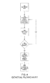
- FIGS. 4 through 7 are flowcharts diagramming the steps automated by the present invention.
- FIGS. 8 through 10 are flowcharts illustrating the steps involved in building the 21 ⁇ 2-dimensional toolpath for some of the various available machining strategies.
- FIGS. 11 and 12 are flowcharts diagramming the steps involved in converting the curves to 21 ⁇ 2-dimensional toolpath for three of the available machining strategies.
- FIG. 13 illustrates mapping a region between boundary curves.
- FIG. 14 illustrates scaling a text item to the proper size.
- FIGS. 15 and 16 illustrate Voronoi diagrams for full and light skeleton patterns.
- FIGS. 1A , 1 B and 1 C a collection of personalized rings are shown. These rings each have one or more panels 105 , which are regions on the ring that can each be personalized by the student purchaser. Each panel 105 can include text 110 , a design 115 , or both.
- FIG. 2 is a workflow diagram illustrating the use of one embodiment of the present invention.
- orders are captured by various channels.
- student consumers may fill out an on-line electronic order form 205 . 2 that is submitted to a web server 210 for storage in a database 220 .
- students and their parents may fill out paper-based order forms 205 . 1 that are turned into a sales representative.
- Each sales rep may forward a set of order forms to the manufacturer's data entry department, where a group of data entry clerks enter the orders into a computer repository database 220 .
- IVR Interactive Voice Response
- a workstation 215 is managed by a production operator. From this workstation 215 , a computer software application can retrieve data for one of the pending orders.
- the order for a class ring includes all of the personalization to be applied to the ring. For example, the order specifies which type of ring to use, where to engrave the student's name, what font to use, where to place school and year information, where to apply icons representative of the student's interests, etc.
- the software application applies all of the personalization elements to a 3D virtual model of the ring. Then it translates the model into a series of instructions describing a path that a milling machine's cutting tool follows while machining a ring. This set of instructions are commonly known as the “toolpath”.
- the toolpath is downloaded to a milling machine 225 and a wax blank of the ring is engraved to the specifications ordered by the student.
- the resulting wax model is then grouped with other wax models and the set of rings are cast and finished 230 , resulting in the customized ring 235 .
- FIG. 3 shows they system architecture of one embodiment of the present invention's personalization system 305 .
- a personalization client 310 is a computer program that provides the production operator with a graphical user interface.
- the personalization client 310 makes requests of a personalization server 315 , which in turn performs all of the complex mathematics to generate the toolpath for a milling machine that will result in a ring as ordered by a student. To do so, data may be retrieved from various databases, such as an order database 220 . 1 and a configuration database 220 . 2 .
- the personalization client 310 can also provide such functionality as: reading barcodes that represent order IDs, displaying order information, managing queues of orders, and communicating post-processed toolpath to the mills.
- a toolpath viewer 325 can be used to provide a preview visualization to the production operator of what will result when the toolpath is applied to the wax blank.
- WNCPlot3D viewer software (sold by Intercim) is used as the toolpath viewer 325 .
- the viewer 325 is used mostly in troubleshooting and setup situations.
- a post-processor 320 (such as Intercim's GPOST post-processor) can be used to translate it to the mill-specific toolpath, which is then downloaded to the milling machine 225 .
- FIG. 2 differentiates the personalization server 315 from the personalization client 310 , in some embodiments both reside on the production operator's workstation 215 . In other embodiments, the software functionality can be implemented without using a client/server architecture.
- FIGS. 4 through 7 provide additional details of one embodiment of the processing performed by the personalization server 315 and the personalization client 310 .
- the first primary step is to get information for the order to be processed 405 . Again, this order information contains information about at least one personalization item to be included in the finished ring.
- the first element to be personalized is processed: the basic geometry for the element is generated 410 and the toolpath is created for the given panel 415 and projected onto the three dimensional surface of the geometric model. The steps of generating geometry and creating toolpath are repeated for each of the remaining personalization elements 420 .
- the toolpath (set of machining instructions) is generated that will create a ring to match the geometric model 430 and 440 .
- the present invention provides a high level of personalization flexibility, such as the ability to project text and icons onto arbitrary product surfaces.
- FIG. 5 shows more detail on how the geometric model is created (step 410 ).
- the model for each type of ring includes one or more panels, which are the personalization regions for the ring.
- each of the panels is retrieved from a repository 505 and then they are assembled together to form the proper geometric model 510 .
- Assembling the text geometry is preceded by retrieving the text requested by the customer as well as a design ID 405 .
- a design ID specifies the product being personalized. For example, it specifies which configuration parameters to use (i.e., boundary curves, product surfaces, fonts, and the like).
- the order data includes an indicator for the desired font to use in personalizing the text. As shown in FIG. 6 .
- this is retrieved 610 and then the operating system is queried for the appropriate font geometry 615 .
- TrueType brand typographic software is used by the operating system to present the font geometry to the application.
- source code from the Microsoft Glyph program can be used to acquire TrueType font geometry from the operating system.
- a set of splines are created 620 .
- data from the TrueType font information returned by the operating system is used to construct curves in spline format.
- the text is then mapped between upper and lower boundary curves which define the panel shape in 2 dimensions. This is accomplished with the font geometry information.
- the first step is to tessellate all of the splines to generate a polyline set for each character of the text 625 .
- the text characters are mapped into a 2D rectangular domain using the kerning information provided with the TrueType font 630 .
- each of the polyline sets are spaced based on kerning data supplied with the font geometry. The spacing is adjusted to meet the minimum spacing requirements associated with the given panel 635 .
- the polyline sets are mapped between the boundary curves 640 so that the characters or icon curves follow the shape of the two boundaries.
- a ruled surface is defined between the two curves. Such a process is discussed in “The NURBS Book” by Les Piegl and Wayne Tiller (pages 337-339) and is illustrated in FIG. 13 . In that figure, the ruled surface 1305 is defined between an upper boundary curve 1310 and a lower boundary curve 1315 .
- FIG. 14 shows a letter “T” 1405 scaled to fit in a domain 1410 .
- the parameterization of the boundary curves will determine the type of mapping.
- Two basic maps are used in one embodiment: “parallel to ends” and “perpendicular to base.”
- the vertical legs of each text character are defined by an interpolation of the slopes of the left and right edges of the boundary shape.
- a “perpendicular to base” technique the vertical legs of the characters are defined as being perpendicular to the base curve of the boundary shape.
- configuration parameters are retrieved from a repository.
- the configuration parameters vary for each ring design.
- the repository may store such data as the font name, character spacing, character thickness, character type (such as raised, incised, etc.), boundary curves, cutter type, and machining pattern.
- FIG. 7 details how to build the toolpath 415 .
- a set of machining patterns and information for the associated cutting tools are retrieved 705 .
- machining patterns a.k.a. strategies
- the following patterns can be used: (a) a raster pattern, wherein Voronoi diagram techniques are used to generate 2D offsets defined by text geometry, cutting tool shape, and cutting depth; (b) a profile pattern, wherein Voronoi diagram techniques are used to generate 2D offsets defined by text geometry, cutting tool shape, and cutting depth; (c) a skeleton pattern, wherein Voronoi diagram techniques are used to generate medial axis transforms defined by text geometry, cutting tool shape, and cutting depth; (d) a light skeleton pattern, wherein Voronoi diagram techniques are used to generate medial axis transforms defined by text geometry, cutting tool shape, and cutting depth; (e) a 2D curve machining with surface projection pattern; and (f) a 3D curve machining pattern.
- the light skeleton pattern it may be generated by constructing the Voronoi diagram of the set of input curves and extracting a subset of the Voronoi diagram that is sometimes referred to as a symmetric axis transform.
- a z-depth is assigned to each point of the subset of the Voronoi diagram, based on the distance from the point to the two curves associated to the point and the shape of the cutting tool.
- the invention projects the curves vertically onto a surface.
- FIGS. 15 and 16 illustrate the construction of the Voronoi diagram to construct the light skeleton pattern.
- the Voronoi diagram 1515 and the light skeleton pattern 1605 are determined.
- the VRONI software library provided by SUNY at Stony Brook (Dr. Martin Held) is used to compute the Voronoi diagrams used by the various machining patterns.
- the geometry being machined is approximated by 21 ⁇ 2-dimensional geometry. That is, it is assumed that the objects are two dimensional with a nearly constant z-height. This assumption is valid for many of the ring manufacturing designs.
- the 21 ⁇ 2-dimensional toolpath is generated by retrieving the type of pattern specified. If the pattern requested is “profile” 706 , the 21 ⁇ 2-dimensional toolpath for the profile pattern is generated 710 . If the pattern requested is “raster” 707 , the 21 ⁇ 2-dimensional toolpath for the raster pattern is generated 715 . Otherwise, a full or light skeleton toolpath is generated 720 .
- the toolpath generated for the personalization element is (in one embodiment) either a simultaneous 4-axis toolpath or a positional 4-axis toolpath.
- the rotational axis is moving from one tool location to another continuously while in the positional version, the tool will remain at a constant rotational axis position, changing only from one panel to the other.
- FIGS. 8 through 10 illustrate flowcharts of how to build the 21 ⁇ 2-dimensional toolpath is referenced in steps 706 through 720 by one embodiment of the invention.
- this process is shown when using a profile machining pattern.
- FIG. 9 shows the steps for a raster machining pattern.
- FIG. 10 shows the steps for a skeleton machining pattern.
- the effective radius of the cutting tool for a cut having a given depth is first calculated 805 .
- the two dimensional offset of the text or icon for that effective cutting tool radius is calculated 810 .
- This is followed by calculating the two dimensional offset of the text or icon for the given depth of cut 815 .
- the two dimensional curves are converted to 21 ⁇ 2-dimensional toolpath 820 . (For further detail of this step, refer to FIG. 12 .)
- the first step is to calculate the profile toolpath 905 .
- the present invention generates parallel curves at step-over distance from each other 910 .
- This process is followed by constraining the parallel two dimensional curves to the regions defined by the profile curves 915 .
- the constrained two dimensional curves are converted to 21 ⁇ 2-dimensional toolpath 920 . (For further detail of this step, refer to FIG. 12 .)
- the first step is to calculate the 21 ⁇ 2-dimensional profile toolpath 1005 .
- the 2D Voronoi diagram is calculated 1010 .
- the present invention then removes portions of the Voronoi diagram that are contained inside the profile regions 1015 .
- the 2 dimensional curves of the subset of the Voronoi curves are converted to 21 ⁇ 2-dimensional toolpath 1020 .
- the toolpath is finished 1025 . Otherwise, if the system is using the full skeleton pattern, then the 21 ⁇ 2-dimensional profile toolpath is appended in order to generate the full skeleton toolpath 1030 .
- the step of generating the 21 ⁇ 2-dimensional toolpath has been detailed above.
- the toolpath is projected onto the surface of the ring 725 . This generates the corresponding three-dimensional toolpath. Once the projection is accomplished, the toolpath is rotated by a specified angle to achieve the final toolpath for that particular personalization panel 730 .
- the toolpath is converted to the generic ACL format 430 . In one embodiment, this conversion is accomplished by a post-processor, such as the Intercim GPOST software product 440 .
- FIGS. 11 and 12 show details of how to convert the curves to 21 ⁇ 2-dimensional toolpath for the skeleton, profile, and raster machining patterns.
- the present invention gets a point in the remaining set of edges from the Voronoi diagram 1120 .
- the distance from that point to the text or icon curves is determined 1125 .
- the depth that corresponds to an effective radius equal to the calculated distance is assigned as a z-value.
- the point with z-value is added to the toolpath 1130 . This repeats for additional points 1135 .
- the present invention first gets a point in the remaining set of edges in the Voronoi diagram 1220 . Then the depth of cut is assigned as a z-value and the point is added with that z-value to the toolpath 1230 . This repeats for additional points 1235 .
Abstract
Description
Claims (40)
Priority Applications (1)
| Application Number | Priority Date | Filing Date | Title |
|---|---|---|---|
| US13/237,247 USRE44696E1 (en) | 2002-12-10 | 2011-09-20 | Automated engraving of a customized jewelry item |
Applications Claiming Priority (3)
| Application Number | Priority Date | Filing Date | Title |
|---|---|---|---|
| US10/315,475 US7069108B2 (en) | 2002-12-10 | 2002-12-10 | Automated engraving of a customized jewelry item |
| US11/415,724 US7593786B2 (en) | 2002-12-10 | 2006-05-02 | Automated engraving of a customized jewelry item |
| US13/237,247 USRE44696E1 (en) | 2002-12-10 | 2011-09-20 | Automated engraving of a customized jewelry item |
Related Parent Applications (1)
| Application Number | Title | Priority Date | Filing Date |
|---|---|---|---|
| US11/415,724 Reissue US7593786B2 (en) | 2002-12-10 | 2006-05-02 | Automated engraving of a customized jewelry item |
Publications (1)
| Publication Number | Publication Date |
|---|---|
| USRE44696E1 true USRE44696E1 (en) | 2014-01-07 |
Family
ID=32468712
Family Applications (3)
| Application Number | Title | Priority Date | Filing Date |
|---|---|---|---|
| US10/315,475 Expired - Lifetime US7069108B2 (en) | 2002-12-10 | 2002-12-10 | Automated engraving of a customized jewelry item |
| US11/415,724 Ceased US7593786B2 (en) | 2002-12-10 | 2006-05-02 | Automated engraving of a customized jewelry item |
| US13/237,247 Expired - Lifetime USRE44696E1 (en) | 2002-12-10 | 2011-09-20 | Automated engraving of a customized jewelry item |
Family Applications Before (2)
| Application Number | Title | Priority Date | Filing Date |
|---|---|---|---|
| US10/315,475 Expired - Lifetime US7069108B2 (en) | 2002-12-10 | 2002-12-10 | Automated engraving of a customized jewelry item |
| US11/415,724 Ceased US7593786B2 (en) | 2002-12-10 | 2006-05-02 | Automated engraving of a customized jewelry item |
Country Status (5)
| Country | Link |
|---|---|
| US (3) | US7069108B2 (en) |
| AU (1) | AU2003300854A1 (en) |
| CA (1) | CA2509548C (en) |
| MX (1) | MXPA05006295A (en) |
| WO (1) | WO2004053653A2 (en) |
Cited By (6)
| Publication number | Priority date | Publication date | Assignee | Title |
|---|---|---|---|---|
| US20130173040A1 (en) * | 2011-12-02 | 2013-07-04 | Jostens, Inc. | System and method for jewelry design |
| US9217996B2 (en) | 2010-02-25 | 2015-12-22 | Jostens, Inc. | Method for digital manufacturing of jewelry items |
| US9582615B2 (en) | 2013-01-16 | 2017-02-28 | Jostens, Inc. | Modeling using thin plate spline technology |
| USD789228S1 (en) | 2013-11-25 | 2017-06-13 | Jostens, Inc. | Bezel for a ring |
| USD906155S1 (en) | 2020-01-28 | 2020-12-29 | Jostens, Inc. | Ring |
| US10905967B1 (en) | 2016-09-07 | 2021-02-02 | Ezra Joseph Satok-Wolman | Component based system for assembling geometric structures |
Families Citing this family (34)
| Publication number | Priority date | Publication date | Assignee | Title |
|---|---|---|---|---|
| US7069108B2 (en) | 2002-12-10 | 2006-06-27 | Jostens, Inc. | Automated engraving of a customized jewelry item |
| US20050149409A1 (en) * | 2004-01-03 | 2005-07-07 | Jay Whaley | Method of producing customer-designed jewerly utilizing services of foundry |
| US7266514B2 (en) * | 2004-02-04 | 2007-09-04 | Hampden Corporation | Method of personalizing an ornamental ring in real-time |
| US20060144549A1 (en) * | 2005-01-06 | 2006-07-06 | Lehmann Todd P | Article of jewelry and method of manufacture |
| JP5013699B2 (en) * | 2005-10-21 | 2012-08-29 | 株式会社キーエンス | Three-dimensional machining data setting device, three-dimensional machining data setting method, three-dimensional machining data setting program, computer-readable recording medium, recorded device, and laser machining device |
| US7814027B2 (en) * | 2006-04-20 | 2010-10-12 | Deluca Joseph G | Matchmaking jewelry and method |
| JP5132900B2 (en) * | 2006-06-28 | 2013-01-30 | 株式会社キーエンス | Laser processing condition setting device, laser processing device, laser processing condition setting method, laser processing condition setting program |
| JP4958489B2 (en) * | 2006-06-30 | 2012-06-20 | 株式会社キーエンス | Laser processing device, laser processing condition setting device, laser processing condition setting method, laser processing condition setting program |
| JP4795886B2 (en) | 2006-07-27 | 2011-10-19 | 株式会社キーエンス | Laser processing device, laser processing condition setting device, laser processing condition setting method, laser processing condition setting program |
| JP4956107B2 (en) * | 2006-09-15 | 2012-06-20 | 株式会社キーエンス | Laser processing data generation apparatus, laser processing data generation method, computer program, and laser marking system |
| WO2008089441A1 (en) * | 2007-01-18 | 2008-07-24 | Jostens, Inc. | System and method for generating instructions for customization |
| US20080177639A1 (en) * | 2007-01-19 | 2008-07-24 | Marc Kuppersmith | System and method for facilitating the retail sale of customizable products |
| WO2008112796A1 (en) | 2007-03-12 | 2008-09-18 | Jostens, Inc. | Method for embellishment placement |
| US20080314081A1 (en) * | 2007-06-25 | 2008-12-25 | Commemorative Brands, Inc. | Commemorative ring with flip-top |
| US20090199129A1 (en) * | 2008-02-06 | 2009-08-06 | Dion Thomas G | System and method for computer program implemented individual unique candle design |
| EP2128802A1 (en) * | 2008-05-29 | 2009-12-02 | Carl Freudenberg KG | Component provided with machine readable identification |
| US8295972B2 (en) * | 2008-10-07 | 2012-10-23 | Celeritive Technologies, Inc. | High performance milling |
| ITAR20090001A1 (en) * | 2009-01-05 | 2010-07-06 | Giorgio Violi | MACHINE FOR THE PRODUCTION OF DRAWINGS AND SCRIPTURES BY ENGRAVING ON OBJECTS OF SPHERICAL FORM, PARTIALLY SPHERICAL, ELLIPTICAL |
| US20100169059A1 (en) * | 2009-02-13 | 2010-07-01 | Grant Thomas-Lepore | Layered Personalization |
| WO2012075430A1 (en) * | 2010-12-03 | 2012-06-07 | The Regents Of The University Of Colorado, A Body Corporate | Cut-fold shape technology for engineered molded fiber boards |
| US9946245B2 (en) | 2011-07-25 | 2018-04-17 | Celeritive Technologies, Inc. | Non-concentric milling |
| US10022833B2 (en) | 2012-05-03 | 2018-07-17 | Celeritive Technologies, Inc. | High performance multi-axis milling |
| TWI457735B (en) * | 2012-07-16 | 2014-10-21 | Wistron Corp | Mold machining method and mold machining system for computer numerical control |
| US20140107827A1 (en) * | 2012-10-15 | 2014-04-17 | Garrett S. Chalmers | Method for Designing and Making Jewelry |
| US9360293B2 (en) * | 2013-03-07 | 2016-06-07 | Quality Casting, Inc. | Contour band matching tool and methods |
| US9329591B2 (en) * | 2013-05-28 | 2016-05-03 | Siemens Product Lifecycle Management Software Inc. | Feature geometry aspect recognition and machining |
| CN103488849A (en) * | 2013-10-12 | 2014-01-01 | 梧州学院 | Method for restoring original design of bright circular polished gemstone by using image processing technology |
| WO2015112078A1 (en) * | 2014-01-23 | 2015-07-30 | Performance Sk8 Holding Inc. | System and method for manufacturing a board body |
| AU2015393678A1 (en) * | 2015-05-01 | 2017-12-07 | A&I Inc. | Jewelry customization system |
| US10430851B2 (en) | 2016-06-09 | 2019-10-01 | Microsoft Technology Licensing, Llc | Peripheral device customization |
| US11609547B2 (en) * | 2016-12-19 | 2023-03-21 | Autodesk, Inc. | Gestural control of an industrial robot |
| CN107944971A (en) * | 2017-12-10 | 2018-04-20 | 梦工场珠宝企业管理有限公司 | Ornament on-line customization method, customization server and client |
| WO2021155200A1 (en) * | 2020-01-29 | 2021-08-05 | America's Collectibles Network, Inc. (Tennessee Corp.) | System and method of bridging 2d and 3d assets for product visualization and manufacturing |
| US11826908B2 (en) | 2020-04-27 | 2023-11-28 | Scalable Robotics Inc. | Process agnostic robot teaching using 3D scans |
Citations (89)
| Publication number | Priority date | Publication date | Assignee | Title |
|---|---|---|---|---|
| US2858897A (en) | 1956-04-13 | 1958-11-04 | Joy Mfg Co | Wheel driving and steering unit |
| US3964915A (en) | 1974-12-26 | 1976-06-22 | Trw Inc. | Investment wax |
| US4004333A (en) | 1973-08-06 | 1977-01-25 | U.S. Amada, Ltd. | Punching, contouring, handling apparatuses and method |
| FR2536969A1 (en) | 1982-12-03 | 1984-06-08 | Bermann Mourrut Francoise | Piece of jewellery and method for producing it |
| US4561061A (en) | 1981-04-06 | 1985-12-24 | Dainippon Screen Mfg. Co., Ltd. | Method of tracing/recording image lines and apparatus therefor |
| US4630309A (en) | 1983-07-04 | 1986-12-16 | Urw Unternehmensberatung Karow Rubow Weber Gmbh | Method and apparatus for automatic digitizing of contour lines |
| US4761865A (en) | 1986-01-17 | 1988-08-09 | Diamants Applications | Process for the mechanized production of jewelry comprising a plurality of small contiguous stones set in a metal support |
| US4771474A (en) | 1983-10-03 | 1988-09-13 | Shaken Co., Ltd. | Apparatus for processing character or pictorial image data |
| US4918611A (en) | 1988-07-21 | 1990-04-17 | Industrial Technology Research Institute | Method and apparatus for controlling laser cutting by image processing |
| US4969201A (en) | 1987-10-08 | 1990-11-06 | Hitachi Software Engineering Co., Ltd. | Method of recognizing a circular arc segment for an image processing apparatus |
| US4972323A (en) * | 1986-12-23 | 1990-11-20 | Roger LeCren | Automatic engraving systems and method |
| US5003498A (en) | 1986-01-13 | 1991-03-26 | Hitachi, Ltd. | Graphic display method |
| US5007098A (en) | 1988-12-30 | 1991-04-09 | Ezel, Inc. | Vectorizing method |
| US5116174A (en) | 1989-11-13 | 1992-05-26 | Kenneth Fried | Method and apparatus for manufacturing jewelry, and an article of jewelry made thereby |
| US5249670A (en) | 1992-03-11 | 1993-10-05 | Jostens, Inc. | Award recognition package |
| US5261768A (en) | 1992-09-23 | 1993-11-16 | Sandia National Laboratories | Automated edge finishing using an active XY table |
| US5329381A (en) * | 1992-02-20 | 1994-07-12 | Payne John H | Automatic engraving method and apparatus |
| US5369736A (en) | 1989-07-12 | 1994-11-29 | Hitachi, Ltd. | Texture mapping method |
| US5473742A (en) | 1994-02-22 | 1995-12-05 | Paragraph International | Method and apparatus for representing image data using polynomial approximation method and iterative transformation-reparametrization technique |
| US5544291A (en) | 1993-11-10 | 1996-08-06 | Adobe Systems, Inc. | Resolution-independent method for displaying a three dimensional model in two-dimensional display space |
| US5548698A (en) | 1994-02-14 | 1996-08-20 | Andersen Corporation | Rule based parametric design apparatus and method |
| US5569003A (en) | 1994-05-13 | 1996-10-29 | Quick-Tag, Inc. | Automated engraving apparatus and method |
| US5587913A (en) | 1993-01-15 | 1996-12-24 | Stratasys, Inc. | Method employing sequential two-dimensional geometry for producing shells for fabrication by a rapid prototyping system |
| US5649079A (en) | 1994-02-28 | 1997-07-15 | Holmes; David I. | Computerized method using isosceles triangles for generating surface points |
| US5668930A (en) | 1993-06-07 | 1997-09-16 | Fanuc Ltd | Off-line teaching method for a robot |
| US5689577A (en) | 1994-10-14 | 1997-11-18 | Picker International, Inc. | Procedure for the simplification of triangular surface meshes for more efficient processing |
| US5739912A (en) | 1991-04-26 | 1998-04-14 | Nippon Telegraph And Telephone Corporation | Object profile measuring method and apparatus |
| US5739822A (en) | 1994-07-27 | 1998-04-14 | International Business Machines Corporation | Data processing system for surfacing a model |
| US5790713A (en) | 1992-06-17 | 1998-08-04 | Fujitsu Limited | Three-dimensional computer graphics image generator |
| US5850222A (en) | 1995-09-13 | 1998-12-15 | Pixel Dust, Inc. | Method and system for displaying a graphic image of a person modeling a garment |
| US5926389A (en) * | 1991-02-15 | 1999-07-20 | Trounson; James E. | Computer control system for generating geometric designs |
| US5926388A (en) * | 1994-12-09 | 1999-07-20 | Kimbrough; Thomas C. | System and method for producing a three dimensional relief |
| US5968564A (en) | 1994-06-02 | 1999-10-19 | Kord Products Limited | Injection molding apparatus |
| US5977007A (en) | 1997-10-30 | 1999-11-02 | Howmet Research Corporation | Erbia-bearing core |
| US6003228A (en) * | 1998-05-14 | 1999-12-21 | Wave Corporation | Method for making a decorative or jewelry item |
| US6083267A (en) | 1997-01-17 | 2000-07-04 | Hitachi, Ltd. | System and method for designing accessory |
| US6085126A (en) | 1997-11-21 | 2000-07-04 | St. Paul Stamp Works, Inc. | System and method for preparing custom designs for multiple types of imprintable media |
| US6101280A (en) | 1994-07-04 | 2000-08-08 | Hewlett-Packard Company | Method and apparatus for compression of electronic ink |
| US6124858A (en) | 1997-04-14 | 2000-09-26 | Adobe Systems Incorporated | Raster image mapping |
| WO2000057254A1 (en) | 1999-03-19 | 2000-09-28 | Laser Optronic Technologies (Proprietary) Limited | Customisation of jewellery |
| US6138055A (en) | 1981-02-27 | 2000-10-24 | Lmi Technologies Inc. | Controlled machining of combustion chambers, gears and other surfaces |
| US6181839B1 (en) | 1996-08-23 | 2001-01-30 | Matsushita Electric Industrial Co., Ltd. | Two-dimensional code reader |
| US6249289B1 (en) | 1996-11-27 | 2001-06-19 | Silicon Graphics, Inc. | Multi-purpose high resolution distortion correction |
| US6260383B1 (en) * | 1999-06-28 | 2001-07-17 | Warren Metallurgical, Inc. | Ring |
| US6300595B1 (en) | 1999-06-03 | 2001-10-09 | High Tech Polishing, Inc. | Method of three dimensional laser engraving |
| WO2001093156A1 (en) | 2000-05-26 | 2001-12-06 | Steven Bradley Pollack | System and method for designing custom jewelry |
| US6349758B1 (en) | 1998-01-13 | 2002-02-26 | Louis E. Bell | Apparatus for forming a pour hole and main sprue in an investment mold for lost wax casting |
| US20020063912A1 (en) * | 2000-11-29 | 2002-05-30 | Barbanell Joseph S. | Personalized stoneless holographic jewelry and method of its production and use |
| US6407361B1 (en) | 1999-06-03 | 2002-06-18 | High Tech Polishing, Inc. | Method of three dimensional laser engraving |
| US20020085748A1 (en) | 2000-10-27 | 2002-07-04 | Baumberg Adam Michael | Image generation method and apparatus |
| US20020092322A1 (en) * | 2001-01-16 | 2002-07-18 | Zieverink Robert M. | Refrigerator art jewelry |
| US6434277B1 (en) | 1998-07-13 | 2002-08-13 | Sony Corporation | Image processing apparatus and method, and medium therefor |
| US20020113865A1 (en) | 1997-09-02 | 2002-08-22 | Kotaro Yano | Image processing method and apparatus |
| US20020128742A1 (en) * | 2001-03-12 | 2002-09-12 | Zieverink Robert M. | Accurate portraits |
| US20020159638A1 (en) | 2001-02-28 | 2002-10-31 | Edward Ratner | Dynamic chain-based thresholding using global characteristics |
| US20020181802A1 (en) | 2001-05-03 | 2002-12-05 | John Peterson | Projecting images onto a surface |
| US20020191863A1 (en) | 2001-06-19 | 2002-12-19 | International Business Machines Corporation | Methods and apparatus for cut-and-paste editing of multiresolution surfaces |
| FR2829366A1 (en) | 2001-09-13 | 2003-03-14 | Francois Xavier Renou | Bracelets, earrings, brooches, necklaces or pendants have camouflage pattern made up of patches of gems of different colors inside engraved borders |
| US6546305B1 (en) | 2000-03-23 | 2003-04-08 | Harry Winston Inc. | Method and apparatus for jewelry design |
| JP2003150666A (en) | 2001-11-16 | 2003-05-23 | Matsumura Gold & Silver Co Ltd | Recording medium for jewelry design system |
| US6568455B2 (en) | 2001-04-10 | 2003-05-27 | Robert M. Zieverink | Jewelry making method using a rapid prototyping machine |
| US6600488B1 (en) | 2000-09-05 | 2003-07-29 | Nvidia Corporation | Tessellation system, method and computer program product with interior and surrounding meshes |
| US6628279B1 (en) | 2000-11-22 | 2003-09-30 | @Last Software, Inc. | System and method for three-dimensional modeling |
| US20040091143A1 (en) | 2001-01-22 | 2004-05-13 | Qingmao Hu | Two and three dimensional skeletonization |
| US20040111178A1 (en) | 2002-12-10 | 2004-06-10 | Saarela Timothy D. | Automated engraving of a customized jewelry item |
| US6763279B2 (en) * | 2001-10-09 | 2004-07-13 | Glen Davis | System and method for efficiently inscribing bullion articles utilizing a milling tool and a numeric controller |
| US20040237822A1 (en) | 2003-05-30 | 2004-12-02 | Clemson University | Ink-jet printing of viable cells |
| US6856314B2 (en) | 2002-04-18 | 2005-02-15 | Stmicroelectronics, Inc. | Method and system for 3D reconstruction of multiple views with altering search path and occlusion modeling |
| US6877916B2 (en) | 2003-03-17 | 2005-04-12 | Irena Khaikin | Method for generating non-repeating patterns for printing |
| US20050089237A1 (en) | 2003-10-24 | 2005-04-28 | Jaehwa Park | Method and apparatus for bezier curve approximation data compression |
| US20050147312A1 (en) | 2004-01-06 | 2005-07-07 | Chen Aubrey K. | Method and apparatus for creating vector representation |
| US20050149409A1 (en) | 2004-01-03 | 2005-07-07 | Jay Whaley | Method of producing customer-designed jewerly utilizing services of foundry |
| US20050222862A1 (en) | 2004-03-30 | 2005-10-06 | Kristen Guhde | System and method for designing custom jewelry and accessories |
| US6978230B1 (en) | 2000-10-10 | 2005-12-20 | International Business Machines Corporation | Apparatus, system, and method for draping annotations on to a geometric surface |
| US6982710B2 (en) | 2001-01-05 | 2006-01-03 | Interuniversitair Micro-Elektronica Centrum (Imec Vzw) | System and method to obtain surface structures of multi-dimensional objects, and to represent those surface structures for animation, transmission and display |
| US20060001664A1 (en) | 2004-04-19 | 2006-01-05 | Carbonera Carlos D | System and method for smoothing three dimensional images |
| US7003371B2 (en) | 2000-08-18 | 2006-02-21 | Amada Company Limited | Apparatus for processing electronic drawing data |
| US7006089B2 (en) | 2001-05-18 | 2006-02-28 | Canon Kabushiki Kaisha | Method and apparatus for generating confidence data |
| FR2880521A1 (en) | 2005-01-12 | 2006-07-14 | Gerard Reynaud | Jewel e.g. ring, fabricating method, involves setting stones, having color shade similar to that of corresponding pixel in small pixel matrix, in each of several tiles of grid that is similar to that of matrix |
| US7091963B2 (en) | 2001-08-01 | 2006-08-15 | Microsoft Corporation | Dynamic rendering of ink strokes with transparency |
| US20060290695A1 (en) | 2001-01-05 | 2006-12-28 | Salomie Ioan A | System and method to obtain surface structures of multi-dimensional objects, and to represent those surface structures for animation, transmission and display |
| US20080177410A1 (en) | 2007-01-18 | 2008-07-24 | Carbonera Carlos D | System and method for generating instructions for customization |
| US20080229784A1 (en) | 2007-03-12 | 2008-09-25 | Carbonera Carlos D | System and method for embellishment placement |
| US20090110307A1 (en) | 2007-10-29 | 2009-04-30 | Markowitz Moshe Itzhak | Method and system for efficient transmission of rich three-dimensional geometry and animation content over narrow band communication networks |
| US20090263624A1 (en) | 2008-04-22 | 2009-10-22 | Materials Solutions | Method of forming an article |
| US20100152873A1 (en) | 2006-01-20 | 2010-06-17 | 3M Innovative Properties Company | Local enforcement of accuracy in fabricated models |
| US7747055B1 (en) | 1998-11-25 | 2010-06-29 | Wake Forest University Health Sciences | Virtual endoscopy with improved image segmentation and lesion detection |
| US20100169059A1 (en) | 2009-02-13 | 2010-07-01 | Grant Thomas-Lepore | Layered Personalization |
| US20110213482A1 (en) | 2010-02-25 | 2011-09-01 | Tim Saarela | Method for digital manufacturing of jewelry items |
-
2002
- 2002-12-10 US US10/315,475 patent/US7069108B2/en not_active Expired - Lifetime
-
2003
- 2003-12-10 MX MXPA05006295A patent/MXPA05006295A/en active IP Right Grant
- 2003-12-10 AU AU2003300854A patent/AU2003300854A1/en not_active Abandoned
- 2003-12-10 CA CA2509548A patent/CA2509548C/en not_active Expired - Fee Related
- 2003-12-10 WO PCT/US2003/039272 patent/WO2004053653A2/en not_active Application Discontinuation
-
2006
- 2006-05-02 US US11/415,724 patent/US7593786B2/en not_active Ceased
-
2011
- 2011-09-20 US US13/237,247 patent/USRE44696E1/en not_active Expired - Lifetime
Patent Citations (101)
| Publication number | Priority date | Publication date | Assignee | Title |
|---|---|---|---|---|
| US2858897A (en) | 1956-04-13 | 1958-11-04 | Joy Mfg Co | Wheel driving and steering unit |
| US4004333A (en) | 1973-08-06 | 1977-01-25 | U.S. Amada, Ltd. | Punching, contouring, handling apparatuses and method |
| US3964915A (en) | 1974-12-26 | 1976-06-22 | Trw Inc. | Investment wax |
| US6138055A (en) | 1981-02-27 | 2000-10-24 | Lmi Technologies Inc. | Controlled machining of combustion chambers, gears and other surfaces |
| US4561061A (en) | 1981-04-06 | 1985-12-24 | Dainippon Screen Mfg. Co., Ltd. | Method of tracing/recording image lines and apparatus therefor |
| FR2536969A1 (en) | 1982-12-03 | 1984-06-08 | Bermann Mourrut Francoise | Piece of jewellery and method for producing it |
| US4630309A (en) | 1983-07-04 | 1986-12-16 | Urw Unternehmensberatung Karow Rubow Weber Gmbh | Method and apparatus for automatic digitizing of contour lines |
| US4771474A (en) | 1983-10-03 | 1988-09-13 | Shaken Co., Ltd. | Apparatus for processing character or pictorial image data |
| US5003498A (en) | 1986-01-13 | 1991-03-26 | Hitachi, Ltd. | Graphic display method |
| US4761865A (en) | 1986-01-17 | 1988-08-09 | Diamants Applications | Process for the mechanized production of jewelry comprising a plurality of small contiguous stones set in a metal support |
| US4972323A (en) * | 1986-12-23 | 1990-11-20 | Roger LeCren | Automatic engraving systems and method |
| US4969201A (en) | 1987-10-08 | 1990-11-06 | Hitachi Software Engineering Co., Ltd. | Method of recognizing a circular arc segment for an image processing apparatus |
| US4918611A (en) | 1988-07-21 | 1990-04-17 | Industrial Technology Research Institute | Method and apparatus for controlling laser cutting by image processing |
| US5007098A (en) | 1988-12-30 | 1991-04-09 | Ezel, Inc. | Vectorizing method |
| US5369736A (en) | 1989-07-12 | 1994-11-29 | Hitachi, Ltd. | Texture mapping method |
| US5116174A (en) | 1989-11-13 | 1992-05-26 | Kenneth Fried | Method and apparatus for manufacturing jewelry, and an article of jewelry made thereby |
| US5926389A (en) * | 1991-02-15 | 1999-07-20 | Trounson; James E. | Computer control system for generating geometric designs |
| US5739912A (en) | 1991-04-26 | 1998-04-14 | Nippon Telegraph And Telephone Corporation | Object profile measuring method and apparatus |
| US5329381A (en) * | 1992-02-20 | 1994-07-12 | Payne John H | Automatic engraving method and apparatus |
| US5249670A (en) | 1992-03-11 | 1993-10-05 | Jostens, Inc. | Award recognition package |
| US5790713A (en) | 1992-06-17 | 1998-08-04 | Fujitsu Limited | Three-dimensional computer graphics image generator |
| US5261768A (en) | 1992-09-23 | 1993-11-16 | Sandia National Laboratories | Automated edge finishing using an active XY table |
| US5587913A (en) | 1993-01-15 | 1996-12-24 | Stratasys, Inc. | Method employing sequential two-dimensional geometry for producing shells for fabrication by a rapid prototyping system |
| US5668930A (en) | 1993-06-07 | 1997-09-16 | Fanuc Ltd | Off-line teaching method for a robot |
| US5544291A (en) | 1993-11-10 | 1996-08-06 | Adobe Systems, Inc. | Resolution-independent method for displaying a three dimensional model in two-dimensional display space |
| US5548698A (en) | 1994-02-14 | 1996-08-20 | Andersen Corporation | Rule based parametric design apparatus and method |
| US5473742A (en) | 1994-02-22 | 1995-12-05 | Paragraph International | Method and apparatus for representing image data using polynomial approximation method and iterative transformation-reparametrization technique |
| US5649079A (en) | 1994-02-28 | 1997-07-15 | Holmes; David I. | Computerized method using isosceles triangles for generating surface points |
| US5569003A (en) | 1994-05-13 | 1996-10-29 | Quick-Tag, Inc. | Automated engraving apparatus and method |
| US5968564A (en) | 1994-06-02 | 1999-10-19 | Kord Products Limited | Injection molding apparatus |
| US6101280A (en) | 1994-07-04 | 2000-08-08 | Hewlett-Packard Company | Method and apparatus for compression of electronic ink |
| US5739822A (en) | 1994-07-27 | 1998-04-14 | International Business Machines Corporation | Data processing system for surfacing a model |
| US5689577A (en) | 1994-10-14 | 1997-11-18 | Picker International, Inc. | Procedure for the simplification of triangular surface meshes for more efficient processing |
| US20010044668A1 (en) | 1994-12-09 | 2001-11-22 | Kimbrough Thomas C. | System and method for producing a three dimensional relief |
| US5926388A (en) * | 1994-12-09 | 1999-07-20 | Kimbrough; Thomas C. | System and method for producing a three dimensional relief |
| US5850222A (en) | 1995-09-13 | 1998-12-15 | Pixel Dust, Inc. | Method and system for displaying a graphic image of a person modeling a garment |
| US6181839B1 (en) | 1996-08-23 | 2001-01-30 | Matsushita Electric Industrial Co., Ltd. | Two-dimensional code reader |
| US6249289B1 (en) | 1996-11-27 | 2001-06-19 | Silicon Graphics, Inc. | Multi-purpose high resolution distortion correction |
| US6083267A (en) | 1997-01-17 | 2000-07-04 | Hitachi, Ltd. | System and method for designing accessory |
| US6124858A (en) | 1997-04-14 | 2000-09-26 | Adobe Systems Incorporated | Raster image mapping |
| US20020113865A1 (en) | 1997-09-02 | 2002-08-22 | Kotaro Yano | Image processing method and apparatus |
| US5977007A (en) | 1997-10-30 | 1999-11-02 | Howmet Research Corporation | Erbia-bearing core |
| US6085126A (en) | 1997-11-21 | 2000-07-04 | St. Paul Stamp Works, Inc. | System and method for preparing custom designs for multiple types of imprintable media |
| US6349758B1 (en) | 1998-01-13 | 2002-02-26 | Louis E. Bell | Apparatus for forming a pour hole and main sprue in an investment mold for lost wax casting |
| US6003228A (en) * | 1998-05-14 | 1999-12-21 | Wave Corporation | Method for making a decorative or jewelry item |
| US6434277B1 (en) | 1998-07-13 | 2002-08-13 | Sony Corporation | Image processing apparatus and method, and medium therefor |
| US7747055B1 (en) | 1998-11-25 | 2010-06-29 | Wake Forest University Health Sciences | Virtual endoscopy with improved image segmentation and lesion detection |
| WO2000057254A1 (en) | 1999-03-19 | 2000-09-28 | Laser Optronic Technologies (Proprietary) Limited | Customisation of jewellery |
| US6407361B1 (en) | 1999-06-03 | 2002-06-18 | High Tech Polishing, Inc. | Method of three dimensional laser engraving |
| US6300595B1 (en) | 1999-06-03 | 2001-10-09 | High Tech Polishing, Inc. | Method of three dimensional laser engraving |
| US6260383B1 (en) * | 1999-06-28 | 2001-07-17 | Warren Metallurgical, Inc. | Ring |
| US6546305B1 (en) | 2000-03-23 | 2003-04-08 | Harry Winston Inc. | Method and apparatus for jewelry design |
| WO2001093156A1 (en) | 2000-05-26 | 2001-12-06 | Steven Bradley Pollack | System and method for designing custom jewelry |
| US7003371B2 (en) | 2000-08-18 | 2006-02-21 | Amada Company Limited | Apparatus for processing electronic drawing data |
| US6600488B1 (en) | 2000-09-05 | 2003-07-29 | Nvidia Corporation | Tessellation system, method and computer program product with interior and surrounding meshes |
| US6978230B1 (en) | 2000-10-10 | 2005-12-20 | International Business Machines Corporation | Apparatus, system, and method for draping annotations on to a geometric surface |
| US20020085748A1 (en) | 2000-10-27 | 2002-07-04 | Baumberg Adam Michael | Image generation method and apparatus |
| US6628279B1 (en) | 2000-11-22 | 2003-09-30 | @Last Software, Inc. | System and method for three-dimensional modeling |
| US20020063912A1 (en) * | 2000-11-29 | 2002-05-30 | Barbanell Joseph S. | Personalized stoneless holographic jewelry and method of its production and use |
| US6982710B2 (en) | 2001-01-05 | 2006-01-03 | Interuniversitair Micro-Elektronica Centrum (Imec Vzw) | System and method to obtain surface structures of multi-dimensional objects, and to represent those surface structures for animation, transmission and display |
| US20060290695A1 (en) | 2001-01-05 | 2006-12-28 | Salomie Ioan A | System and method to obtain surface structures of multi-dimensional objects, and to represent those surface structures for animation, transmission and display |
| US20020092322A1 (en) * | 2001-01-16 | 2002-07-18 | Zieverink Robert M. | Refrigerator art jewelry |
| US20040091143A1 (en) | 2001-01-22 | 2004-05-13 | Qingmao Hu | Two and three dimensional skeletonization |
| US20020159638A1 (en) | 2001-02-28 | 2002-10-31 | Edward Ratner | Dynamic chain-based thresholding using global characteristics |
| US20020128742A1 (en) * | 2001-03-12 | 2002-09-12 | Zieverink Robert M. | Accurate portraits |
| US6568455B2 (en) | 2001-04-10 | 2003-05-27 | Robert M. Zieverink | Jewelry making method using a rapid prototyping machine |
| US20020181802A1 (en) | 2001-05-03 | 2002-12-05 | John Peterson | Projecting images onto a surface |
| US7006089B2 (en) | 2001-05-18 | 2006-02-28 | Canon Kabushiki Kaisha | Method and apparatus for generating confidence data |
| US20020191863A1 (en) | 2001-06-19 | 2002-12-19 | International Business Machines Corporation | Methods and apparatus for cut-and-paste editing of multiresolution surfaces |
| US7091963B2 (en) | 2001-08-01 | 2006-08-15 | Microsoft Corporation | Dynamic rendering of ink strokes with transparency |
| US7236180B2 (en) | 2001-08-01 | 2007-06-26 | Microsoft Corporation | Dynamic rendering of ink strokes with transparency |
| FR2829366A1 (en) | 2001-09-13 | 2003-03-14 | Francois Xavier Renou | Bracelets, earrings, brooches, necklaces or pendants have camouflage pattern made up of patches of gems of different colors inside engraved borders |
| US6763279B2 (en) * | 2001-10-09 | 2004-07-13 | Glen Davis | System and method for efficiently inscribing bullion articles utilizing a milling tool and a numeric controller |
| JP2003150666A (en) | 2001-11-16 | 2003-05-23 | Matsumura Gold & Silver Co Ltd | Recording medium for jewelry design system |
| US6856314B2 (en) | 2002-04-18 | 2005-02-15 | Stmicroelectronics, Inc. | Method and system for 3D reconstruction of multiple views with altering search path and occlusion modeling |
| US7593786B2 (en) | 2002-12-10 | 2009-09-22 | Jostens, Inc. | Automated engraving of a customized jewelry item |
| US20060200269A1 (en) | 2002-12-10 | 2006-09-07 | Jostesn, Inc. | Automated engraving of a customized jewelry item |
| US20040111178A1 (en) | 2002-12-10 | 2004-06-10 | Saarela Timothy D. | Automated engraving of a customized jewelry item |
| WO2004053653A2 (en) | 2002-12-10 | 2004-06-24 | Jostens, Inc. | Automated engraving of a customized jewelry item |
| US7069108B2 (en) * | 2002-12-10 | 2006-06-27 | Jostens, Inc. | Automated engraving of a customized jewelry item |
| US6877916B2 (en) | 2003-03-17 | 2005-04-12 | Irena Khaikin | Method for generating non-repeating patterns for printing |
| US20040237822A1 (en) | 2003-05-30 | 2004-12-02 | Clemson University | Ink-jet printing of viable cells |
| US20050089237A1 (en) | 2003-10-24 | 2005-04-28 | Jaehwa Park | Method and apparatus for bezier curve approximation data compression |
| US20050149409A1 (en) | 2004-01-03 | 2005-07-07 | Jay Whaley | Method of producing customer-designed jewerly utilizing services of foundry |
| US20050147312A1 (en) | 2004-01-06 | 2005-07-07 | Chen Aubrey K. | Method and apparatus for creating vector representation |
| US20050222862A1 (en) | 2004-03-30 | 2005-10-06 | Kristen Guhde | System and method for designing custom jewelry and accessories |
| US20060001664A1 (en) | 2004-04-19 | 2006-01-05 | Carbonera Carlos D | System and method for smoothing three dimensional images |
| US20120075297A1 (en) | 2004-04-19 | 2012-03-29 | Carbonera Carlos D | System and method for smoothing three dimensional images |
| US8085266B2 (en) | 2004-04-19 | 2011-12-27 | Jostens, Inc. | System and method for smoothing three dimensional images |
| FR2880521A1 (en) | 2005-01-12 | 2006-07-14 | Gerard Reynaud | Jewel e.g. ring, fabricating method, involves setting stones, having color shade similar to that of corresponding pixel in small pixel matrix, in each of several tiles of grid that is similar to that of matrix |
| US20100152873A1 (en) | 2006-01-20 | 2010-06-17 | 3M Innovative Properties Company | Local enforcement of accuracy in fabricated models |
| US7856285B2 (en) | 2007-01-18 | 2010-12-21 | Jostens, Inc. | System and method for generating instructions for customization |
| US20110144785A1 (en) | 2007-01-18 | 2011-06-16 | Carbonera Carlos D | System and method for generating instructions for customization |
| US20080177410A1 (en) | 2007-01-18 | 2008-07-24 | Carbonera Carlos D | System and method for generating instructions for customization |
| US20080229784A1 (en) | 2007-03-12 | 2008-09-25 | Carbonera Carlos D | System and method for embellishment placement |
| US8126683B2 (en) | 2007-03-12 | 2012-02-28 | Jostens, Inc. | System and method for embellishment placement |
| US20120116729A1 (en) | 2007-03-12 | 2012-05-10 | Carbonera Carlos D | System and method for embellishment placement |
| US20090110307A1 (en) | 2007-10-29 | 2009-04-30 | Markowitz Moshe Itzhak | Method and system for efficient transmission of rich three-dimensional geometry and animation content over narrow band communication networks |
| US20090263624A1 (en) | 2008-04-22 | 2009-10-22 | Materials Solutions | Method of forming an article |
| US20100169059A1 (en) | 2009-02-13 | 2010-07-01 | Grant Thomas-Lepore | Layered Personalization |
| US20110213482A1 (en) | 2010-02-25 | 2011-09-01 | Tim Saarela | Method for digital manufacturing of jewelry items |
Non-Patent Citations (16)
| Title |
|---|
| "2004 Your Guide to feature-based Manufacturing", Jun. 2003, Engineering Geometry Systems, Tenth Edition, pp. 13-66, 153-182, 291-298, 311-342, 369, 380, 441-457. |
| Delcam plc, "ArtCAM JewelSmith User Gu de", Issue 7.1 Sep. 11, 2004. |
| Hendricks, Bob. "Henricks Mfg. Jewellers-CNC Production of Wax Models Boosts Ring Sales by 50%", www.techno-isel.com/CNC-Routers/Testimonials/Articles/Hendricks.htm, Nov. 25, 2001. |
| International Search Report and Written Opinion. International Patent Application No. PCT/US2008/056705. Mailed Apr. 8, 2008. |
| International Search Report for PCT Application No. PCT/US2005/013469, mailed Sep. 6, 2005. |
| Park, Sang C. "Polygonal extrusion", The Visual Computer, Jan. 28, 2003, Springer-Verlag, pp. 38-49. |
| Patent Abstracts of Japan, vol. 2003, No. 9, Sep. 3, 2003. |
| Rowan, Mark, "Automated Methods for Evolutionary Pave Jewellery Design", The University of Birmingham School of Computer Science, Jan. 15, 2006. |
| Sigmund et al. "Transformations between Pictures from 2D to 3D", Jun. 2000, Journal of Intelligent and Robotic Systems, vol. 28, pp. 69-84. |
| Stam, Jos et al. "Quad/Triangle Subdivision", Computer Graphics Forum, vol. 22, No. 1, Apr. 2003, pp. 79-85. |
| Stamati et al. "A Parametric Feature-based CAD System for Reproducing Traditional Pierced Jewellery", Computer-Aided Design, vol. 37, Issue 4, pp. 431-449, Apr. 2005. |
| Techjewel, "TechGems 3.0", User Guide, 2004. |
| Wannarumon et al. "Intelligent Computer System for Jewelry Design Support", Computer Aided Design and Applications, 1 (1-4) 551-558, 2004. |
| Wannarumon et al. "Rapid Prototyping and Tooling Technology in Jewelry CAD", Computer-Aided Design and Applications, Jan. 2004, vol. 1, No. 1-4 (pp. 569-575). |
| Wick et al. "Tool and Manufacturing Engineers Handbook", 1998, Society of Manufacturing Engineers, vol. 3, Chapter 15, pp. 15-1, 15-2, and 15-25. |
| Wirth, Joachim "Rapid Modeling", Carl Hanser Verlag, Munchen, 2002, pp. 60-62, 170-177. |
Cited By (7)
| Publication number | Priority date | Publication date | Assignee | Title |
|---|---|---|---|---|
| US9217996B2 (en) | 2010-02-25 | 2015-12-22 | Jostens, Inc. | Method for digital manufacturing of jewelry items |
| US20130173040A1 (en) * | 2011-12-02 | 2013-07-04 | Jostens, Inc. | System and method for jewelry design |
| US9208265B2 (en) * | 2011-12-02 | 2015-12-08 | Jostens, Inc. | System and method for jewelry design |
| US9582615B2 (en) | 2013-01-16 | 2017-02-28 | Jostens, Inc. | Modeling using thin plate spline technology |
| USD789228S1 (en) | 2013-11-25 | 2017-06-13 | Jostens, Inc. | Bezel for a ring |
| US10905967B1 (en) | 2016-09-07 | 2021-02-02 | Ezra Joseph Satok-Wolman | Component based system for assembling geometric structures |
| USD906155S1 (en) | 2020-01-28 | 2020-12-29 | Jostens, Inc. | Ring |
Also Published As
| Publication number | Publication date |
|---|---|
| US20040111178A1 (en) | 2004-06-10 |
| CA2509548C (en) | 2014-04-29 |
| WO2004053653A3 (en) | 2009-09-03 |
| MXPA05006295A (en) | 2006-03-17 |
| AU2003300854A8 (en) | 2009-10-08 |
| US7593786B2 (en) | 2009-09-22 |
| WO2004053653A2 (en) | 2004-06-24 |
| CA2509548A1 (en) | 2004-06-24 |
| AU2003300854A1 (en) | 2004-06-30 |
| US20060200269A1 (en) | 2006-09-07 |
| US7069108B2 (en) | 2006-06-27 |
Similar Documents
| Publication | Publication Date | Title |
|---|---|---|
| USRE44696E1 (en) | Automated engraving of a customized jewelry item | |
| US7856285B2 (en) | System and method for generating instructions for customization | |
| US6459952B1 (en) | Method of and system for producing 3-D carved signs using automatic tool path generation and computer-simulation techniques | |
| US6775581B2 (en) | Horizontally-structured CAD/CAM modeling for virtual concurrent product and process design | |
| US5197013A (en) | Method of forming a carved sign using an axially rotating carving tool | |
| US8515826B2 (en) | Made-to-order direct digital manufacturing enterprise | |
| US5353390A (en) | Construction of elements for three-dimensional objects | |
| GB2190268A (en) | C.a.d. | |
| EP2248105A1 (en) | Representing flat designs to be printed on curves of a 3-dimensional product | |
| US20020133253A1 (en) | Horizontally-structured CAD/CAM modeling for virtual fixture and tooling processes | |
| CN105212452B (en) | A kind of manufacture method of the pendant body being carved with personalized embossed portrait | |
| Campbell et al. | The potential for the bespoke industrial designer | |
| US6735489B1 (en) | Horizontally structured manufacturing process modeling | |
| US20020133803A1 (en) | Enhancement to horizontally-structured CAD/CAM modeling | |
| Ryou et al. | Development of a data interface for rapid prototyping in STEP-NC | |
| CN110442081A (en) | Numerical-control processing method, device, system and storage medium based on SVG | |
| JPH0821089B2 (en) | Solid model shape definition method in CAD / CAM system | |
| Hughes | CAD for the Workshop | |
| Kochan | Features Rapid prototyping wins widespread acceptance | |
| JP2001236373A (en) | Design support system | |
| WO2023234989A1 (en) | System and method for authoring high quality renderings and generating manufacturing output of custom products | |
| Sanchez et al. | Using rapid prototyping for free-form shapes in architectural scale models | |
| CN110096821A (en) | Product customization method, system and readable storage medium storing program for executing | |
| Trivedi et al. | Application of CAD, Rapid Prototyping and Reverse Engineering in Handicrafts Sector–A Success Story | |
| Gausemeier et al. | Virtual Prototyping—Design and realistic presentation of industrial products |
Legal Events
| Date | Code | Title | Description |
|---|---|---|---|
| AS | Assignment |
Owner name: CREDIT SUISSE AG, AS COLLATERAL AGENT, NEW YORK Free format text: SECURITY AGREEMENT;ASSIGNORS:JOSTENS, INC.;THE LEHIGH PRESS LLC;REEL/FRAME:033882/0213 Effective date: 20140923 |
|
| AS | Assignment |
Owner name: THE LEHIGH PRESS LLC, NEW YORK Free format text: RELEASE BY SECURED PARTY;ASSIGNOR:CREDIT SUISSE AG;REEL/FRAME:036949/0754 Effective date: 20151102 Owner name: JOSTENS, INC., NEW YORK Free format text: RELEASE BY SECURED PARTY;ASSIGNOR:CREDIT SUISSE AG;REEL/FRAME:036949/0754 Effective date: 20151102 |
|
| FPAY | Fee payment |
Year of fee payment: 8 |
|
| AS | Assignment |
Owner name: BANK OF AMERICA, N.A., NORTH CAROLINA Free format text: FIRST LIEN SECURITY AGREEMENT;ASSIGNOR:JOSTENS, INC.;REEL/FRAME:047975/0229 Effective date: 20181221 |
|
| AS | Assignment |
Owner name: BANK OF AMERICA, N.A., NORTH CAROLINA Free format text: SECOND LIEN SECURITY AGREEMENT;ASSIGNOR:JOSTENS, INC.;REEL/FRAME:047980/0131 Effective date: 20181221 |
|
| AS | Assignment |
Owner name: JOSTENS, INC., MINNESOTA Free format text: ASSIGNMENT OF ASSIGNORS INTEREST;ASSIGNORS:SAARELA, TIMOTHY D;CARBONERA, CARLOS D;FRISCH, MICHAEL J;AND OTHERS;REEL/FRAME:051613/0529 Effective date: 20021211 |
|
| MAFP | Maintenance fee payment |
Free format text: PAYMENT OF MAINTENANCE FEE, 12TH YEAR, LARGE ENTITY (ORIGINAL EVENT CODE: M1553); ENTITY STATUS OF PATENT OWNER: LARGE ENTITY Year of fee payment: 12 |