USRE35740E - Telecommunication system - Google Patents
Telecommunication system Download PDFInfo
- Publication number
- USRE35740E USRE35740E US08/245,606 US24560694A USRE35740E US RE35740 E USRE35740 E US RE35740E US 24560694 A US24560694 A US 24560694A US RE35740 E USRE35740 E US RE35740E
- Authority
- US
- United States
- Prior art keywords
- facsimile
- signals
- signal
- demodulators
- transmission network
- Prior art date
- Legal status (The legal status is an assumption and is not a legal conclusion. Google has not performed a legal analysis and makes no representation as to the accuracy of the status listed.)
- Expired - Lifetime
Links
Images


Classifications
-
- H—ELECTRICITY
- H04—ELECTRIC COMMUNICATION TECHNIQUE
- H04N—PICTORIAL COMMUNICATION, e.g. TELEVISION
- H04N19/00—Methods or arrangements for coding, decoding, compressing or decompressing digital video signals
- H04N19/90—Methods or arrangements for coding, decoding, compressing or decompressing digital video signals using coding techniques not provided for in groups H04N19/10-H04N19/85, e.g. fractals
-
- H—ELECTRICITY
- H04—ELECTRIC COMMUNICATION TECHNIQUE
- H04J—MULTIPLEX COMMUNICATION
- H04J3/00—Time-division multiplex systems
- H04J3/17—Time-division multiplex systems in which the transmission channel allotted to a first user may be taken away and re-allotted to a second user if the first user becomes inactive, e.g. TASI
- H04J3/172—Digital speech interpolation, i.e. DSI
-
- H—ELECTRICITY
- H04—ELECTRIC COMMUNICATION TECHNIQUE
- H04N—PICTORIAL COMMUNICATION, e.g. TELEVISION
- H04N1/00—Scanning, transmission or reproduction of documents or the like, e.g. facsimile transmission; Details thereof
- H04N1/00095—Systems or arrangements for the transmission of the picture signal
- H04N1/001—Systems or arrangements for the transmission of the picture signal specially adapted for transmission via digital wireline networks
-
- H—ELECTRICITY
- H04—ELECTRIC COMMUNICATION TECHNIQUE
- H04N—PICTORIAL COMMUNICATION, e.g. TELEVISION
- H04N1/00—Scanning, transmission or reproduction of documents or the like, e.g. facsimile transmission; Details thereof
- H04N1/00127—Connection or combination of a still picture apparatus with another apparatus, e.g. for storage, processing or transmission of still picture signals or of information associated with a still picture
- H04N1/00281—Connection or combination of a still picture apparatus with another apparatus, e.g. for storage, processing or transmission of still picture signals or of information associated with a still picture with a telecommunication apparatus, e.g. a switched network of teleprinters for the distribution of text-based information, a selective call terminal
-
- H—ELECTRICITY
- H04—ELECTRIC COMMUNICATION TECHNIQUE
- H04N—PICTORIAL COMMUNICATION, e.g. TELEVISION
- H04N1/00—Scanning, transmission or reproduction of documents or the like, e.g. facsimile transmission; Details thereof
- H04N1/32—Circuits or arrangements for control or supervision between transmitter and receiver or between image input and image output device, e.g. between a still-image camera and its memory or between a still-image camera and a printer device
- H04N1/333—Mode signalling or mode changing; Handshaking therefor
- H04N1/33307—Mode signalling or mode changing; Handshaking therefor prior to start of transmission, input or output of the picture signal only
- H04N1/33323—Mode signalling or mode changing; Handshaking therefor prior to start of transmission, input or output of the picture signal only transmission mode only, e.g. speed
-
- H—ELECTRICITY
- H04—ELECTRIC COMMUNICATION TECHNIQUE
- H04N—PICTORIAL COMMUNICATION, e.g. TELEVISION
- H04N1/00—Scanning, transmission or reproduction of documents or the like, e.g. facsimile transmission; Details thereof
- H04N1/32—Circuits or arrangements for control or supervision between transmitter and receiver or between image input and image output device, e.g. between a still-image camera and its memory or between a still-image camera and a printer device
- H04N1/333—Mode signalling or mode changing; Handshaking therefor
- H04N1/33346—Mode signalling or mode changing; Handshaking therefor adapting to a particular standardised protocol
-
- H—ELECTRICITY
- H04—ELECTRIC COMMUNICATION TECHNIQUE
- H04N—PICTORIAL COMMUNICATION, e.g. TELEVISION
- H04N2201/00—Indexing scheme relating to scanning, transmission or reproduction of documents or the like, and to details thereof
- H04N2201/32—Circuits or arrangements for control or supervision between transmitter and receiver or between image input and image output device, e.g. between a still-image camera and its memory or between a still-image camera and a printer device
- H04N2201/333—Mode signalling or mode changing; Handshaking therefor
- H04N2201/33307—Mode signalling or mode changing; Handshaking therefor of a particular mode
- H04N2201/33342—Mode signalling or mode changing; Handshaking therefor of a particular mode of transmission mode
- H04N2201/3335—Speed or rate
-
- H—ELECTRICITY
- H04—ELECTRIC COMMUNICATION TECHNIQUE
- H04N—PICTORIAL COMMUNICATION, e.g. TELEVISION
- H04N2201/00—Indexing scheme relating to scanning, transmission or reproduction of documents or the like, and to details thereof
- H04N2201/32—Circuits or arrangements for control or supervision between transmitter and receiver or between image input and image output device, e.g. between a still-image camera and its memory or between a still-image camera and a printer device
- H04N2201/333—Mode signalling or mode changing; Handshaking therefor
- H04N2201/33307—Mode signalling or mode changing; Handshaking therefor of a particular mode
- H04N2201/33342—Mode signalling or mode changing; Handshaking therefor of a particular mode of transmission mode
- H04N2201/33364—Type of modulation; Type of channel, e.g. digital or analog; Type of communication, e.g. half-duplex or full-duplex
Definitions
- the present invention relates to communications apparatus generally and more particularly to telecommunication systems with facsimile demodulation and modulation capabilities.
- TASI Time Assignment Speech Interpolation
- control information such as the assignment, synchronization and identification information is transmitted along the communication channels instead of on separate signaling channels as in the prior art.
- the signaling communication channel assignment information is also supplied via the voice channels rather than via the signaling channels.
- DCME Digital Circuit Multiplication Equipment
- DSI Digital Speech Interpolation
- ADPCM adaptive pulse code modulation
- the system detects voiceband data transmission and compresses it according to an optimal ADPCM adapted for voiceband data.
- the optimal ADPCM adapted for voiceband data compresses the voiceband data at a 2:1 rate whereas the compression rate of the DSI and the ADPCM for speech is 6:1.
- the overall compression rate of a DCME is approaching 3:1.
- the present invention seeks to provide a telecommunication system with improved facsimile signal compression capabilities.
- a telecommunication system for interconnecting a plurality of telephone communication trunks to a transmission network, the system comprising transmission apparatus at at least a first end of the transmission network and receiving apparatus at at least a second end of the transmission network.
- the transmission apparatus includes apparatus for detecting signals on the plurality of telephone communication trunks and classifying the signals at least as selected facsimile signals and other signals, first apparatus for demodulating the selected facsimile signals, second apparatus for compressing the other signals, and apparatus for communicating the nature of signals transmitted along the transmission network.
- the receiving apparatus includes apparatus for receiving communications from the apparatus for communicating for determining the nature of signals received along the transmission network, third means for modulating the selected facsimile signals received along the transmission network, and fourth means for decompressing the other signals received along the transmission network.
- demodulation and modulation may be complete including, for example, descrambling and scrambling, or incomplete not including scrambling and descrambling.
- the other signals comprise voice signals and voiceband data signals.
- the second apparatus comprises both apparatus for compressing the voice signals and apparatus for compressing the voiceband data signals.
- the fourth apparatus comprises both apparatus for decompressing the voice signals and apparatus for decompressing the voiceband data signals.
- the selected facsimile signals are Group 3 facsimile signals.
- the apparatus for detecting and classifying includes apparatus for detecting signal activity, apparatus for detecting the presence of voiceband data signals and apparatus for detecting the presence of group facsimile signals, comprising apparatus for detecting a sequence of flag characters.
- the demodulating apparatus comprises a plurality of facsimile demodulators, each having a different mode of operation corresponding to a group 3 facsimile signal, apparatus for initially supplying incoming selected facsimile signals simultaneously to the plurality of facsimile demodulators, apparatus for determining which of the plurality of facsimile demodulators initially successfully demodulates an incoming selected facsimile signal, and apparatus for utilizing the facsimile demodulator which initially successfully demodulates an incoming selected facsimile signal for continuing demodulation of the incoming selected facsimile signal. Since there are many facsimile transmissions which do not adhere to the standard protocol definitions as defined in CCITT Red Book Rec.
- the data rate and mode of operation of the incoming facsimile signal cannot be derived from a protocol analysis. It is an object of the present invention to provide facsimile signal classification by waveform analysis, rather than protocol analysis. Thus, at the beginning of each facsimile signal burst, a plurality of facsimile demodulators are needed to simultaneously demodulate the incoming facsimile signals.
- the demodulating apparatus comprises facsimile signal demodulator and forward error correction apparatus wherein the forward error correction apparatus is operative to protect the output of the facsimile demodulator.
- An object of the present invention is to provide a facsimile signal compression ratio between 4:1 and 6:1, a ratio much higher than that achievable by treating facsimile transmissions a voiceband data signals.
- the present invention achieves the desired compression ratio by demodulating facsimile modem signals and transmitting that information in binary data form to the far end terminal where the original facsimile mode signal is reproduced.
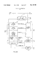
- FIG. 1 is a functional block diagram illustration of the transmit side and the receive side of the system showing graphically functions of the international telephone multiplication system, including the facsimile signal compression functions, constructed and operative in accordance with a preferred embodiment of the present invention
- FIGS. 2A and 2B are block diagram illustrations of elements of the transmit circuitry constructed and operative in accordance with a preferred embodiment of the present invention
- FIG. 3 is a block diagram illustration of the facsimile demodulator useful in the apparatus of FIGS. 2A and 2B;
- FIGS. 4A and 4B are block diagram illustrations of elements or the receive circuitry constructed and operative in accordance with a preferred embodiment of the present invention
- FIG. 5 is a block diagram illustration of the facsimile modulator useful in the apparatus of FIGS. 3A and 3B;
- FIG. 6 is a block diagram illustration of the signal flow from a facsimile machine, through local telephone lines, to a switching center useful in understanding the system of FIG. 1.
- FIG. 6 illustrates the data flow from a facsimile machine through a local telephone system to a transmission network.
- a facsimile machine 10 according to CCITT Red Book, Malaga-Torremolinos 1984, Recommendations T.4 and T.30, comprises a facsimile scanner and encoder 12, according to CCITT Red Book Recommendation T.4, which produces a binary bit stream, at rates up to 9.6 kbit/s, representing a compressed version of the scanned page, and a modulator 14, such as the R96MFX Monofax by Rockwell International, which modulates the binary bit stream onto an analog waveform for transmission through local analog telephone systems.
- a modulator 14 such as the R96MFX Monofax by Rockwell International, which modulates the binary bit stream onto an analog waveform for transmission through local analog telephone systems.
- the Group 3 facsimile call procedure is defined in detail in CCITT Red Book Rec. T.30.
- the facsimile call begins with a 2100 Hz. tone from the called terminal, followed by a coordination dialog between the two facsimile machines at a rate of 300 bit/s, modulated according to CCITT Red Book Rec. V.21, channel 2.
- the facsimile messages are transmitted, page by page, at data rates of 2400, 4800, 7200, and 9600 bit/s, modulated according to CCITT Red Book Rec. V.27 ter for the two lower rates and according to CCITT Red Book Rec. V.29 for the two upper rates.
- CCITT Red Book Rec. T.30 also allows for non-standard 300 bit/s protocols.
- An analog to digital (A/D) converter 16 receives the analog waveform and samples the signal in order to transform it to a standard 64 kbit/s pulse code modulated (PCM) digital signal.
- the digital PCM signal is then transmitted, as one time slot or a 2.048 or a 1.544 Mbit/s signal, via a digital exchange 18, such as the 4ESS from AT&T, which may subsequently transmit it to a transmission system, such as is described hereinbelow.
- the digital signal produced by the facsimile scanner 12 is a binary data signal and the digital signal produced by the A/D converter 16 is in the form of digital samples of an analog waveform.
- the two rates are significantly different (up to 9.6 kbit/s vs. 64 kbit/s) and thus, the transmission of the binary data via current methods of telephony is wasteful.
- the transmission efficiency of digital links is increased by reproducing the originally scanned and encoded binary data from the PCM signal of the modulated analog waveform and then transmitting it along a transmission network as a 9.6 kbit/s signal.
- the binary data is transmitted as a 16 kbit/s signal which comprises the 9.6 kbit/s signal and additional error correction code, thus significantly increasing the robustness of the transmission in presence of line errors.
- the system of the present invention achieves a 6:1 compression ratio for facsimile transmissions and with error correction it achieves a 4:1 compression ratio.
- FIG. 1 is an overall functional system block diagram of the transmission and reception end of a telecommunication system, indicating three methods of signal compression as well as the trunk expanding functions of the various elements of the telecommunication system.
- the transmit side is described with respect to FIG. 1.
- the receive side is mirror symmetric and will not be described with respect to FIG. 1.
- Many of the components of the telecommunication system are substantially similar to those described and claimed in the aforesaid U.S. Pat. No. 4,717,096, which is incorporated herein by reference, and therefore, will not be described in detail.
- the telecommunication system described in FIG. 1 can be implemented in a point to point configuration, in a multiclique configuration, and in a multidestination configuration, as defined in CCITT Blue Book Rec. G.763. Additionally, it can be implemented as an access terminal for traffic compression into a packet switching network.
- the transmission apparatus includes a trunk PCM interface (TDLI) 20 which is operative to provide interfacing between 1.544 Mbit/s or 2.048 Mbit/s PCM signals and the internal 2.048 Mbit/s (NRZ) signals employed in the telecommunication system. It is operative to provide synchronization plesiochronous buffering and optional format conversion.
- TDLI trunk PCM interface
- TDLI 20 Downstream of TDLI 20 there is provided a time slot interchange (TSI) 22 which provides time slot mapping. It enables up to ten 24-channel bit streams to be regrouped into eight 30/32 channel bit streams.
- TSI time slot interchange
- Digital speech interpolation circuitry (DSI) 24 provides voice compression by means of the time assignment speech interpolation (TASI) of U.S. Pat. No. 4,523,309 and is operative to compress up to 240 trunks generally into 62 bearer channels. Additionally, DSI 24 provides detection circuitry for classifying incoming signals as selected facsimile signals, such as Group 3 facsimile signals, and as other signals where other signals typically include speech, tone and non-facsimile voiceband data. This enables the transmission apparatus to separately compress facsimile signals and to apply the conventional compression techniques for speech and non-facsimile voiceband data signals.
- TASI time assignment speech interpolation
- a signal compression circuit 25 typically comprised of Adaptive Differential Pulse Code Modulation (ADPCM) circuitry 26 and Variable Bit Rate (VBR) circuitry 28, voiceband data optimized algorithm circuitry 27 and facsimile modem 29.
- ADPCM Adaptive Differential Pulse Code Modulation
- VBR Variable Bit Rate
- ADPCM circuitry 26 employs an ADPCM algorithm, in accordance with the Red Book CCITT G.721 recommendation for compressing speech.
- VBR circuitry 28 is typically provided in conjunction with ADPCM 26 and is operative to effectively create additional bearer channels (in excess of 62) to overcome periods of traffic overload, as described in aforesaid U.S. Pat. No. 4,747,096.
- the ADPCM 26 and the VBR 28, in conjunction with the DSI 24, provide a compression ratio of typically 6:1 for speech signals. It will be appreciated that circuitry employing other speech compression techniques, such as 16 kbit/s speech coding, can replace the ADPCM 26 circuitry.
- Voiceband data is routed through voiceband data optimized algorithm 27 which employs ADPCM codecs specifically optimized for reliable transmission of voiceband data, as described in aforesaid U.S. Pat. No. 4,747,096.
- the voiceband data algorithm is transparent to voiceband data signals and provides a 2:1 compression ratio. It will be appreciated that the voiceband data compression may be implemented using other algorithms, such as that of CCITT Blue Book, Melbourne 1988, Rec. G.723.
- facsimile modem 29 for reproducing a plurality of original facsimile binary data from a plurality of PCM signals, for optionally incorporating error correction information into the plurality of original facsimile binary data and for multiplexing the resultant signals.
- the optional error correction function is typically provided when the transmission network is of the type where performance is typically degraded.
- Multiplexer 31 multiplexes the output of the signal compression stage, comprising ADPCM 26, VBR 28, voiceband data algorithm 27 and facsimile modem 29 into one generally fully populated 2.048 or 1.544 Mbit/s signal. At each sample period, which is typically 125 microseconds, multiplexer 31 produces one bit frame with bits from compressed channels.
- An alternative embodiment of the invention comprises a multiplexer 31 which incorporates wideband packet technology, as described in the aforementioned paper by R. W. Muise et al entitled "Experiments in Wideband Packet Technology".
- the multiplexer 31 is operative to act as a Packet Assembler (PA) to gather and packetize a sequence of samples of compressed speech, voiceband data or facsimile data and to subsequently transmit the packets to a transmission network.
- PA Packet Assembler
- FIG. 2 illustrates in block diagram form certain elements of the transmission apparatus of the telecommunication system pertaining to the present invention and corresponding to the functional block diagram of FIG. 1.
- FIG. 2 illustrates in block diagram form certain elements of the transmission apparatus of the telecommunication system pertaining to the present invention and corresponding to the functional block diagram of FIG. 1.
- a complete description of the remaining elements can be found in aforesaid U.S. Pat. No. 4,747,096.
- Eight 2.048 Mbit/s bit streams emerging from the TSI 22 are supplied to the DSI circuitry 24 and are directed in parallel to a transmit delay memory 50, to a facsimile detector 53 and to other detectors, such as speech and tone detection circuitry 52.
- Speech and tone detection (SPD) circuitry 52 typically comprises four SPD circuits, each of which receives 2 ⁇ 2.048 Mbit/s digital streams from the transmit TSI circuitry 22.
- the SPD circuitry 52 is operative to examine each time slot for the present of speech energy above an adjustable threshold which is normally set at -32 dBmO.
- a main CPU 44 If speech energy is present, a main CPU 44 is notified of the time slot that has active speech. Additionally, the tone detector portion of the SPD circuitry 52 examines the active speech for the continuous presence of a 2100 Hz tone (CCITT Red Book Rec. G.164 or Rec. V.25 for voiceband data or Rec. T.30 for facsimile data). When the tone is detected, the main CPU 44 is notified.
- a 2100 Hz tone CITT Red Book Rec. G.164 or Rec. V.25 for voiceband data or Rec. T.30 for facsimile data.
- Facsimile detector 53 additionally receives all eight of the 2.048 Mbit/s bit streams received from TSI 22 and detects the presence of facsimile signals on them. Since Group 3 facsimile systems begin their 300 bit/s transmissions with a preamble, defined in the 1984 CCITT Red Book Recommendation T.30 paragraph 5.3.1 to be a series of flag characters transmitted for one second on a 300 bit/s signal, it will be appreciated that the preamble is unique to facsimile systems and thus, can be utilized for reliable detection of facsimile signals; other data protocols transmit at most one or two flag characters. Thus, facsimile detector 53 detects a facsimile transmission upon identifying at least five consecutive flag characters.
- facsimile detector 53 notifies the main CPU 44 of the trunk channel in which it occurs. If the detection occurs for a trunk channel which is not classified as carrying facsimile signals, then the main CPU 44 marks the trunk channel as a facsimile trunk channel. Until marked otherwise, the trunk channel remains as a facsimile trunk channel and any further detections of a facsimile transmission on that trunk channel are ignored.
- the main CPU 44 typically based on the Intel 80286 microcomputer, controls the DSI operation as well as other functions of the telecommunication system. Its major task, as part of the transmission apparatus, is to receive activity information about facsimile transmissions and other signals, such as speech, tone and voiceband data, and to assign an available bearer bit portion to the active trunk. In order to do so, it routes the time slots of the eight 2.048 Mbit/s channels, via a transmit Digital Speech Interpolation (DSI) switch 56, to either of the ADPCM 26, the voiceband data algorithm 27 or the facsimile modem 29, depending on the results of the SPD and tone detector 52 and the facsimile detector 53.
- DSI Digital Speech Interpolation
- Main CPU 44 also indicates to a facsimile CPU 80 which is part of the facsimile modem 29 and which is described in more detail hereinbelow, in which time slot it will receive a facsimile transmission and in which bit portion it should transmit the demodulated facsimile transmission.
- the main CPU 44 additionally detects the completion of a facsimile transmission on a facsimile channel.
- the software for the main CPU 44 is taken mostly from apparatus of the type described in the aforesaid U.S. Pat. No. 4,747,096.
- the system switches to a facsimile signal path.
- the switching takes place during the first silent period during facsimile "handshake" following detection. Effecting the switching during the silent period avoids undesirable signal transients.
- the transmit DSI switch 56 receives 8 ⁇ 2.048 Mbit/s digital streams from the transmit delay 50 and selects, in response to commands from the main CPU 44, an appropriate time slot.
- the standard 2.048 Mbit/s bit stream contains 30 speech time slots (TS); however, in accordance with U.S. Pat. No. 4,747,096, when TS 16 is not used for the transmission of signaling information, 31 time slots are available for speech.
- two bit streams of up to 62 time slots during operation at normal speech traffic levels one bit stream with up to 31 voiceband data signals and one bit stream with up to 31 facsimile signals are provided.
- an additional 20 time slots are provided for use during periods of traffic overload, as a result of VBR operation.
- the 144 available time slots form an output of five 2.048 Mbit/s digital streams where the fifth 2.048 Mbit/s digital strum comprises the 20 additional time slots.
- the remaining 11 time slots of the fifth 2.048 Mbit/s digital stream are unused.
- the first two and last one of the five 2.048 Mbit/s digital streams are dedicated to trunk channels with speech activity, the third is dedicated to trunks with non-facsimile voiceband data signals, and the fourth is dedicated to trunks with facsimile transmissions.
- DSI 24 also comprises a message generator 54 which receives 2 bytes (16 bits) of message information from the main CPU 44.
- the message information indicates to the receive circuitry the location, on the bearer bit stream, of the assigned bits for each compressed trunk channel and the type of traffic, speech, voiceband data or facsimile data, carried therein.
- Signal compression circuitry 25 comprises a signal compression assembly 64 which receives the five 2.048 Mbit/s digital streams from the transmitting DSI switch 56.
- the signal compression assembly 64 comprises ADPCM encoders and data optimized ADPCM encoders, fully described in aforesaid U.S. Pat. No. 4,747,096, and facsimile demodulators 67 with optional Forward Error Correction elements (FEC) 69, as described hereinbelow.
- FEC Forward Error Correction elements
- Each facsimile demodulator 67 demodulates the 64 kbit/s PCM bit stream received from the DSI switch 56, thus reconstructing the original scanned and encoded bit stream produced by the facsimile machine 10.
- the optional FEC 69 adds error correction information to the signal to increase the rate of the signal from up to 9.6 kbit/s to 16 kbit/s, a rate which is a submultiple of the 64 kbit/s standard rate or the bearer bit stream.
- Multiplexer 31 comprises a buffer memory 68 which combines the outputs of the signal compression assembly 64 into one 2.048 Mbit/s bearer signal. According to the traffic on the transmission network, it will assign nibble time slots to compressed speech and voiceband data signals and the appropriately sized time slots to demodulated facsimile signals, as described hereinbelow.
- buffer memory 68 stores the output of the signal compression assembly 64 and generates, typically every packet interval of 16 msec, packets of typically 128 4 bit samples with an additional 40 bits of packet header information. It should be noted that under overload traffic conditions, the number of bits for each sample will be smaller due to the operation of the VBR 28.
- Buffer memory 68 releases the packets under control of the main CPU 44 which receives the speech, voiceband data and facsimile signal activity information from SPD and tone detector 52 and facsimile detector 53 every packet interval and assigns bearer bit portions to each active trunk channel.
- facsimile demodulator 67 comprises a plurality of facsimile demodulators 126, such as the R96MFX Monofax from Rockwell International, and a plurality of PCM decoders 128 where each PCM decoder 128 is directly connected to a facsimile demodulator 126.
- a typical transmission apparatus will comprise 40 facsimile demodulators 126 and 40 PCM decoders 128.
- the 40 facsimile demodulators 126 and 40 PCM decoders 128 are needed in order to decode and demodulate facsimile signals from 31 incoming facsimile trunk channels due to the initial overhead of the five demodulators 126.
- one incoming time slot is routed to typically five PCM decoders 128 via a facsimile transmit TSI (TTSI) 124, such as the PEB 2040 PCM Switch from Siemens.
- TTSI 124 typically selects the five PCM decoders 128 based on which five facsimile demodulators 126 are currently available.
- each PCM decoder 128 converts the incoming PCM signal to the original analog telephone waveform and sends the resultant signal to its corresponding facsimile demodulator 126. It will be appreciated that the PCM decoders 128 are included in order to utilize inexpensive facsimile demodulators 126, such as the Rockwell R96MFX, specifically designed for facsimile machines.
- Each of the five facsimile demodulators 126 is tuned to one of the five standard modes of operation for facsimile data, that is, 2.4 or 4.8 kbit/s modulated according Rec. V.27 ter, 7.2 or 9.6 kbit/s modulated according to Rec. V.29 or 300 bit/s, modulated according to Rec. V.21.
- a facsimile demodulation system which utilizes one standard facsimile demodulator 126 per facsimile transmission might be unable to interpret the non-standard protocols and thus, be unable to demodulate facsimile transmissions. Therefore, according to a preferred embodiment of the present invention, five facsimile demodulators 126 are utilized to identify the mode of operation of every portion of a facsimile transmission whether it be the 300 bit/s standard or non-standard dialog or the up to 9.6 kbit/s page transmission.
- the demodulated data are sent to a buffer 130 and stored there until the demodulator tuned to the correct bit rate and mode of operation is identified.
- the identification typically takes 0.3 seconds to achieve a positive identification of either a V.29 or V.21 modem by a given demodulator, after which the remaining four demodulators 126 are available and the data they produced in buffer 130 is ignored. Should no positive identification of either the V.29 or V.21 modems is made during the 0.3 second interval and if during this interval an 1800 Hz tone is detected, then the two demodulators which are tuned to the two alternative transmission rates of the V.27 modem continue to operate. Once positive identification is made by either of those two demodulators, the demodulator which did not make a positive identification becomes available and its output in the buffer 130 is ignored.
- the identifying demodulator 126 continues demodulating the signal and sending it to the buffer 130 until the signal terminates, typically at the end of the transmission of one page or at the end of a 300 bit/s message transmission.
- a 0.3 second delay is sufficient to avoid loss of the beginning of the transmitted signal. This is achieved by commencing transmission of the training sequence characteristic of the V.27 modem once identification of the 1800 Hz signal is made but before positive identification of which transmission mode (i.e. 4.8 or 2.4 kbit/s) has been made.
- the buffer 130 is operative to receive the data from the facsimile demodulators 126 as 8 bit words and to organize it such that, on average, a 9.6 kbit/s bit stream is sent. If the demodulated information is at a rate less than the maximal 9.6 kbit/s, then the data rate is increased to 9.6 kbit/s by dummy bit insertion.
- the buffer 130 achieves the 9.6 kbit/s average bit stream by ensuring that generally 48 bits are sent within milliseconds.
- the 48 bits are organized such that at every millisecond, either 10 bits or 9 bits are transmitted.
- three channels of facsimile data are multiplexed into 32 bits, transmitted in 8 sampling frames as 4 bit nibbles per frame.
- a selector 136 selects, under control of a facsimile transmit CPU (TCPU) 134, the correctly demodulated and multiplexed signals stored in buffer 130 sends them to multiplexer 31 as one partly populated 2.048 Mbit/s digital bit stream.
- TCPU facsimile transmit CPU
- the signal from the selector 136 is routed through FEC 69 which adds forward error correction to the 9.6 kbit/s signal, typically using the Hamming (15,11) code.
- FEC 69 which adds forward error correction to the 9.6 kbit/s signal, typically using the Hamming (15,11) code.
- 10 or 9 bits described hereinabove, are added 1 or 2 dummy bits, respectively, where one of the bits serves as a message bit to indicate the number of original bits, to produce 11 bits, another 4 of error correction based on the Hamming (15,11) code, and a final dummy bit to increase the bit count to 16.
- two channels of facsimile data are multiplexed into a 32 kbit/s channel, producing a 4:1 compression ratio, i.e. transmission of 4 trunks of 64 kbit/s PCM signals via a single 64 kbit/s time slot in the bearer bit stream.
- facsimile demodulator 67 The operation of the facsimile demodulator 67 is controlled by facsimile CPU 134 which polls the status of the demodulators 126 via a status and control read/write 132, selects five demodulators 126 upon reception of a signal burst, tunes each one to a different standard mode of operation, and indicates to TTSI 124 to switch the current time slot to the five PCM decoders 128. Additionally, it identifies the demodulator 126 which is tuned to the correct mode of operation and indicates to the selector 136 to transmit the data from the identified demodulator 126 to the buffer memory 68, or alternatively, to FEC 69 and from there to buffer memory 68.
- the facsimile CPU 134 additionally is connected to the main CPU 44 which indicates to the facsimile CPU 134 which time slots have facsimile data in them, when the facsimile signal burst commences or terminates, and when the facsimile transmission is complete.
- the completion of a facsimile transmission on a facsimile channel is defined according to the following criteria:
- a silence period lasting for at least 10 seconds is detected by SPD and tone detector 52 (FIG. 2A); or
- the five facsimile demodulators 126 attempting to demodulate the facsimile transmission fail to do so within a predetermined length of time, typically 500 ms.
- condition 1 main CPU 44 causes any following signal bursts on that trunk channel to be switched to an ADPCM encoder for speech. If condition 2 is true, the trunk channel is switched to a data optimized ADPCM encoder.
- FIG. 4 illustrates in clock diagram form certain elements of the reception end of a telecommunication system pertaining to the present invention.
- the reception end corresponds to the mirror of the functional block diagram of FIG. 1 and the signal progresses from a BDLI, to a signal decompression unit, to DSI circuitry and finally, to a TDLI, as described in aforesaid U.S. Pat. No. 4,747,096.
- the receive circuitry of FIG. 4 comprises a message receiver 94 (FIG. 3B) which looks for an exclusive message identification code and the message contents following it. Once detected, the message contents are transferred to the main CPU 44 which decodes it to discover the location, on the bearer bit stream, of the assigned bits for each compressed trunk channel and the type of traffic, speech, voiceband data or facsimile data, carried therein. As noted in U.S. Pat. No. 4,747,096, the main CPU 44 controls both the transmit and receive functions of the system and, in receive mode, controls DSI switch 95 in accordance with the assignment messages received.
- the generally fully populated 2.048 Mbit/s delayed output of receive delay 90 is supplied to a buffer memory 96 which forms part of signal decoding circuitry 98.
- the buffer memory 96 outputs to a plurality of decoders 100, each comprising voice ADPCM decoders 101, data optimized ADPCM decoders 103, and facsimile encoders 105 with optional Error Correction (EC) 107, and is controlled by the main CPU 44 through control memory 97.
- decoders 100 each comprising voice ADPCM decoders 101, data optimized ADPCM decoders 103, and facsimile encoders 105 with optional Error Correction (EC) 107, and is controlled by the main CPU 44 through control memory 97.
- EC Error Correction
- the received compressed signals are routed to the appropriate decoder type 101, 103 or 105, along 2.048 Mbit/s digital bit streams, in accordance with the messages received.
- Each set of voice ADPCM decoders 101 and each set of data optimized ADPCM decoders 103 can potentially produce two 2.048 Mbit/s digital bit streams of 8-bit PCM samples upon decoding one fully populated 2.048 Mbit/s digital bit stream of compressed signals.
- Each set of facsimile encoders 105 can potentially produce one 2.048 Mbit/s digital bit stream of 8-bit PCM per sample channels upon encoding one partly populated 2.048 Mbit/s digital bit stream of 9.6 Kbit s demodulated facsimile signals, 6:1 decompression is provided when Error Correction EC 107 is not implemented and 4:1 decompression is provided when EC 107 is employed.
- buffer memory 96 receives packets of samples of either compressed speech, non-facsimile data or facsimile data. Buffer memory 96 is operative to store the received packets and to individually release the samples to the appropriate one of the plurality of decoders 100.
- the receive DSI 95 switch receives the 2.048 Mbit/s digital streams of 8-bit PCM samples from the signal decoders 100. They are switched to eight 2.048 Mbit/s bit streams under control of CPU 44, in accordance with the routing message received from the far end terminal.
- FIG. 5 illustrates the elements of the facsimile encoder 105 and of the optional EC 107.
- the EC 107 performs error correction on the 16 kbit/s demodulated signal with error correction information received from buffer memory 96.
- the EC 107 first strips the signal of the dummy sixteenth bit.
- the EC 107 corrects any errors produced by the transmission and produces an 11 bit corrected signal.
- one or two dummy bits, respectively are subsequently stripped off, according to the status of the message dummy bit.
- the original 9 or 10 bit signal is sent to a buffer 140.
- facsimile decoder 105 comprises a plurality of facsimile modulators 142, such as the R96MFX Monofax from Rockwell International, and a plurality of PCM coders 144, where each PCM coder 144, is directly connected to a facsimile modulator 142.
- a typical facsimile decoder 105 comprises 31 facsimile modulators 142 and 31 PCM coders 144.
- the facsimile decoder 105 operates as follows.
- the 9.6 kbit/s signal is received by butter 140 as sequences of 9 or 10 bits.
- Buffer 140 stores the bits as they arrive and rebuilds the signal as an 8 bit signal which it then sends to a facsimile modulator 142 which has been tuned, by a facsimile Receive CPU (RCPU) 146, to the mode of operation by which the signal was demodulated on the transmit side. If the received facsimile data was originally scanned and encoded at a rate lower than 9.6 kbit/s, then the additional dummy bits are stripped in the buffer 140 and the 8 bit signal is sent to a facsimile modulator at a respectively lower rate.
- RCPU facsimile Receive CPU
- the analog telephone waveform resulting from the facsimile modulator 142 is then sent to the corresponding PCM coder 144 which encodes the analog signal as a PCM signal.
- the plurality of PCM signals produced by the PCM decoders 144 are routed to the appropriate time slot in the trunk bit stream by a facsimile Receive TSI (RTSI) 148, such as the PEB 2040 PCM Switch from Siemens.
- RTSI facsimile Receive TSI
- facsimile RCPU 146 is operative to indicate to the buffer 140 how to rebuild the 8 bit signal and to which facsimile modulator 142 to send the rebuilt signal. It also tunes the selected facsimile modulator 142 to the correct mode of operation according to directions received from the main CPU 44. Finally, it indicates to the facsimile RTSI 148 the time slots on the trunk bit stream corresponding to the outputs of the plurality of PCM coders 144.
- a facsimile compression system such as described hereinabove can be constructed outside of an telecommunication system using elements functionally similar to those described hereinabove.
- incorporating such a system within an existing system such as a digital circuit multiplication system or a speech packetization system, reduces the number of new elements which must be built since many of the necessary elements are already incorporated into the existing system.
Abstract
Description
Claims (37)
Priority Applications (1)
| Application Number | Priority Date | Filing Date | Title |
|---|---|---|---|
| US08/245,606 USRE35740E (en) | 1989-03-02 | 1994-05-19 | Telecommunication system |
Applications Claiming Priority (4)
| Application Number | Priority Date | Filing Date | Title |
|---|---|---|---|
| IL8946189A IL89461A (en) | 1989-03-02 | 1989-03-02 | Facsimile telecommunication compression system |
| IL89461 | 1989-03-02 | ||
| US07/451,748 US5117453A (en) | 1989-03-02 | 1989-12-18 | Telecommunication system |
| US08/245,606 USRE35740E (en) | 1989-03-02 | 1994-05-19 | Telecommunication system |
Related Parent Applications (1)
| Application Number | Title | Priority Date | Filing Date |
|---|---|---|---|
| US07/451,748 Reissue US5117453A (en) | 1989-03-02 | 1989-12-18 | Telecommunication system |
Publications (1)
| Publication Number | Publication Date |
|---|---|
| USRE35740E true USRE35740E (en) | 1998-03-03 |
Family
ID=11059738
Family Applications (2)
| Application Number | Title | Priority Date | Filing Date |
|---|---|---|---|
| US07/451,748 Ceased US5117453A (en) | 1989-03-02 | 1989-12-18 | Telecommunication system |
| US08/245,606 Expired - Lifetime USRE35740E (en) | 1989-03-02 | 1994-05-19 | Telecommunication system |
Family Applications Before (1)
| Application Number | Title | Priority Date | Filing Date |
|---|---|---|---|
| US07/451,748 Ceased US5117453A (en) | 1989-03-02 | 1989-12-18 | Telecommunication system |
Country Status (10)
| Country | Link |
|---|---|
| US (2) | US5117453A (en) |
| EP (1) | EP0529104B1 (en) |
| JP (1) | JP2847167B2 (en) |
| AT (1) | ATE125406T1 (en) |
| BR (1) | BR9000974A (en) |
| DE (2) | DE69021083T2 (en) |
| DK (1) | DK0529104T3 (en) |
| ES (1) | ES2040692T3 (en) |
| GR (2) | GR930300088T1 (en) |
| IL (1) | IL89461A (en) |
Cited By (12)
| Publication number | Priority date | Publication date | Assignee | Title |
|---|---|---|---|---|
| EP1014750A2 (en) * | 1998-12-23 | 2000-06-28 | Eci Telecom Ltd. | Method, system and apparatus for transmitting coded telecommunication signals |
| US6246490B1 (en) * | 1994-11-11 | 2001-06-12 | Siemens Aktiengesellschaft | Method and arrangement for the transmission of facsimile-encoded information between multimedia-capable communication terminal equipment |
| US20020015415A1 (en) * | 2000-05-08 | 2002-02-07 | Yukimasa Sugino | Transmission apparatus capable of transmitting high speed modem signal |
| US6453473B1 (en) | 1998-09-15 | 2002-09-17 | John C. Watson, Jr. | Access device and system for managing television and data communications through a cable television network |
| EP1252775A2 (en) * | 2000-01-06 | 2002-10-30 | QUALCOMM Incorporated | Method and system for transparently determining call service options |
| US20030123466A1 (en) * | 2000-05-21 | 2003-07-03 | Oren Somekh | Modem relay over packet based network |
| US20030185230A1 (en) * | 2000-06-14 | 2003-10-02 | Abraham Fisher | Distributed modem |
| US6956817B1 (en) * | 1999-05-13 | 2005-10-18 | Nec Corporation | Communication system |
| US20060182131A1 (en) * | 2005-01-21 | 2006-08-17 | L-3 Communications Corporation | Gateway interface control |
| US7230977B1 (en) | 2000-05-21 | 2007-06-12 | Surf Communication Solutions Ltd. | Back-to-back modem repeater |
| US7355735B1 (en) | 2000-06-14 | 2008-04-08 | Yona Sivan | Real time fax over packet based network |
| US7406072B1 (en) | 2000-05-21 | 2008-07-29 | Surf Communication Solutions | Modem relay over packet based network |
Families Citing this family (23)
| Publication number | Priority date | Publication date | Assignee | Title |
|---|---|---|---|---|
| EP0474172A3 (en) * | 1990-09-06 | 1993-03-03 | Teletron Ltd. | Telephone line monitoring apparatus and method |
| US5307174A (en) * | 1991-01-11 | 1994-04-26 | Mitsubishi Denki Kabushiki Kaisha | High efficiency facsimile transmission apparatus |
| JP2771369B2 (en) * | 1991-10-24 | 1998-07-02 | 日本電気株式会社 | Audio encoding / decoding device |
| US5490199A (en) * | 1992-02-21 | 1996-02-06 | At&T Corp. | Non-intrusive network-based analysis of facsimile transmissions |
| JP2760217B2 (en) * | 1992-07-01 | 1998-05-28 | 三菱電機株式会社 | Digital line multiplex transmission equipment |
| FI92894C (en) * | 1992-08-17 | 1995-01-10 | Nokia Telecommunications Oy | Arrangements for streamlining data transmission in a digital cellular radio network |
| US5410416A (en) * | 1993-03-16 | 1995-04-25 | At&T Corp. | Simultaneous multi-access, low-speed/high-speed, multi-delivery fax gateway |
| US5404394A (en) * | 1993-05-24 | 1995-04-04 | Comsat Corporation | Secure communication system |
| GB2294614B (en) * | 1994-10-28 | 1999-07-14 | Int Maritime Satellite Organiz | Communication method and apparatus |
| US5533004A (en) * | 1994-11-07 | 1996-07-02 | Motorola, Inc. | Method for providing and selecting amongst multiple data rates in a time division multiplexed system |
| SE504010C2 (en) * | 1995-02-08 | 1996-10-14 | Ericsson Telefon Ab L M | Method and apparatus for predictive coding of speech and data signals |
| JP3199648B2 (en) * | 1996-03-19 | 2001-08-20 | 三菱電機株式会社 | Signal discriminator, signal transmitting apparatus in voice frequency band, and signal discriminating method |
| US5892816A (en) * | 1996-11-15 | 1999-04-06 | Qualcomm, Incorporated | Method and apparatus for detecting facsimile transmission |
| US6434169B1 (en) * | 1997-10-31 | 2002-08-13 | Alcatel Canada Inc. | Voiceband/modem signal relay |
| US6381250B1 (en) | 1998-01-23 | 2002-04-30 | Innovative Communications Technologies, Inc. | Capacity allocation system using semi-autonomous network elements to implement and control a transmission schedule |
| US6426959B1 (en) | 1998-01-20 | 2002-07-30 | Innovative Communications Technologies, Inc. | System and method for facilitating component management in a multiple vendor satellite communications network |
| JPH11289445A (en) | 1998-04-02 | 1999-10-19 | Mitsubishi Electric Corp | Facsimile signal relay transmission system |
| US6075847A (en) * | 1999-02-10 | 2000-06-13 | Qualcomm Inc. | Method and apparatus for detection of fax calls |
| IL130711A0 (en) * | 1999-06-30 | 2000-06-01 | Eci Telecom Ltd | Telecommunication system and a method for using same |
| JP3761795B2 (en) * | 2000-04-10 | 2006-03-29 | 三菱電機株式会社 | Digital line multiplexer |
| US7221684B1 (en) | 2002-01-08 | 2007-05-22 | Cisco Technology, Inc. | Increasing network efficiency using packet compression and decompression |
| US20040179555A1 (en) * | 2003-03-11 | 2004-09-16 | Cisco Technology, Inc. | System and method for compressing data in a communications environment |
| US7733793B1 (en) | 2003-12-10 | 2010-06-08 | Cisco Technology, Inc. | System and method for suppressing silence data in a network environment |
Citations (29)
| Publication number | Priority date | Publication date | Assignee | Title |
|---|---|---|---|---|
| JPS61121634A (en) * | 1984-11-19 | 1986-06-09 | Fujitsu Ltd | Picture switching system |
| JPS61198941A (en) * | 1985-02-28 | 1986-09-03 | Fujitsu Ltd | Transfer speed variable type voice data multiplex system |
| US4691347A (en) * | 1985-02-15 | 1987-09-01 | American Telephone And Telegraph Company, At&T Bell Laboratories | Method and apparatus for controlling a conference |
| JPS62230130A (en) * | 1986-03-31 | 1987-10-08 | Toshiba Corp | Time division multiplex transmission system |
| US4703477A (en) * | 1986-02-28 | 1987-10-27 | American Telephone And Telegraph Company At&T Bell Laboratories | Packet information field data format |
| US4704716A (en) * | 1985-12-31 | 1987-11-03 | American Telephone And Telegraph Company, At&T Bell Laboratories | Method and apparatus for establishing a wideband communication facility through a communication network having narrow bandwidth channels |
| JPS6326044A (en) * | 1986-07-18 | 1988-02-03 | Nec Corp | Voice coding device |
| US4726043A (en) * | 1986-11-28 | 1988-02-16 | American Telephone And Telegraph Company | Data decision-directed timing and carrier recovery circuits |
| US4726019A (en) * | 1986-02-28 | 1988-02-16 | American Telephone And Telegraph Company, At&T Bell Laboratories | Digital encoder and decoder synchronization in the presence of late arriving packets |
| US4730345A (en) * | 1986-04-04 | 1988-03-08 | American Telephone And Telegraph Company | Vestigial sideband signal decoder |
| US4736389A (en) * | 1986-08-04 | 1988-04-05 | American Telephone And Telegraph Company | Technique for synthesizing the modulation of a time varying waveform with a data signal |
| JPS6393238A (en) * | 1986-10-07 | 1988-04-23 | Nec Corp | Electronic exchange |
| US4748620A (en) * | 1986-02-28 | 1988-05-31 | American Telephone And Telegraph Company, At&T Bell Laboratories | Time stamp and packet virtual sequence numbering for reconstructing information signals from packets |
| US4754386A (en) * | 1986-05-30 | 1988-06-28 | Atlantic Telephone And Telegraph Company, At&T Bell Laboratories | D.C. voltage converter with overload protection |
| US4759037A (en) * | 1986-04-28 | 1988-07-19 | American Telephone And Telegraph Company | Passband equalization of modulated quadrature-related carrier signals |
| US4759039A (en) * | 1986-10-20 | 1988-07-19 | American Telephone & Telegraph Company | Simplified recovery of data signals from quadrature-related carrier signals |
| US4763019A (en) * | 1986-09-09 | 1988-08-09 | American Telephone And Telegraph Company, At&T Bell Laboratories | Apparatus comprising harmonic generation means |
| US4763317A (en) * | 1985-12-13 | 1988-08-09 | American Telephone And Telegraph Company, At&T Bell Laboratories | Digital communication network architecture for providing universal information services |
| US4769833A (en) * | 1986-03-31 | 1988-09-06 | American Telephone And Telegraph Company | Wideband switching system |
| US4774496A (en) * | 1986-02-28 | 1988-09-27 | American Telephone And Telegraph Company, At&T Bell Laboratories | Digital encoder and decoder synchronization in the presence of data dropouts |
| US4780884A (en) * | 1986-03-03 | 1988-10-25 | American Telephone And Telegraph Company, At&T Bell Laboratories | Suppressed double-sideband communication system |
| US4790003A (en) * | 1987-04-27 | 1988-12-06 | American Telephone And Telegraph Company, At&T Information Systems | Message service system network |
| US4837798A (en) * | 1986-06-02 | 1989-06-06 | American Telephone And Telegraph Company | Communication system having unified messaging |
| US4864612A (en) * | 1987-10-23 | 1989-09-05 | American Telephone And Telegraph Company | Method of avoiding accidental actuation of maintenance equipment in a communications network |
| US4870497A (en) * | 1988-01-22 | 1989-09-26 | American Telephone And Telegraph Company | Progressive transmission of high resolution two-tone facsimile images |
| US4894823A (en) * | 1986-02-28 | 1990-01-16 | American Telephone And Telegraph Company | Time stamping for packet system nodes |
| US4894633A (en) * | 1988-12-12 | 1990-01-16 | American Telephone And Telegraph Company | Fuse Apparatus |
| US4916691A (en) * | 1988-10-28 | 1990-04-10 | American Telephone And Telegraph Company | Telecommunications switching system |
| US4922348A (en) * | 1989-02-10 | 1990-05-01 | American Telephone And Telegraph Company | Facsimile service |
Family Cites Families (8)
| Publication number | Priority date | Publication date | Assignee | Title |
|---|---|---|---|---|
| US4523309A (en) * | 1978-12-05 | 1985-06-11 | Electronics Corporation Of Israel, Ltd. | Time assignment speech interpolation apparatus |
| US4352957A (en) * | 1980-03-17 | 1982-10-05 | Storage Technology Corporation | Speech detector circuit with associated gain control for a tasi system |
| IL74965A (en) * | 1985-04-17 | 1990-07-12 | Israel Electronics Corp | Combination tasi and adpcm apparatus |
| JP2528824B2 (en) * | 1985-12-18 | 1996-08-28 | 株式会社日立製作所 | Voice / data composite communication method |
| JP2584447B2 (en) * | 1987-03-25 | 1997-02-26 | 富士通株式会社 | Time division multiplexer |
| JPH0831935B2 (en) * | 1987-09-21 | 1996-03-27 | 国際電信電話株式会社 | Facsimile communication method |
| JPS6481442A (en) * | 1987-09-22 | 1989-03-27 | Nec Corp | Variable band compression and connection system |
| US4805208A (en) * | 1988-01-15 | 1989-02-14 | Niravoice, Inc. | Modem compression system for telephone network |
-
1989
- 1989-03-02 IL IL8946189A patent/IL89461A/en not_active IP Right Cessation
- 1989-12-18 US US07/451,748 patent/US5117453A/en not_active Ceased
-
1990
- 1990-02-09 JP JP2031349A patent/JP2847167B2/en not_active Expired - Fee Related
- 1990-02-23 DE DE69021083T patent/DE69021083T2/en not_active Expired - Lifetime
- 1990-02-23 EP EP90850077A patent/EP0529104B1/en not_active Expired - Lifetime
- 1990-02-23 ES ES90850077T patent/ES2040692T3/en not_active Expired - Lifetime
- 1990-02-23 AT AT90850077T patent/ATE125406T1/en not_active IP Right Cessation
- 1990-02-23 DE DE199090850077T patent/DE529104T1/en active Pending
- 1990-02-23 DK DK90850077.0T patent/DK0529104T3/en active
- 1990-03-02 BR BR909000974A patent/BR9000974A/en not_active IP Right Cessation
-
1993
- 1993-09-30 GR GR930300088T patent/GR930300088T1/en unknown
-
1994
- 1994-05-19 US US08/245,606 patent/USRE35740E/en not_active Expired - Lifetime
-
1995
- 1995-10-16 GR GR950402837T patent/GR3017738T3/en unknown
Patent Citations (30)
| Publication number | Priority date | Publication date | Assignee | Title |
|---|---|---|---|---|
| JPS61121634A (en) * | 1984-11-19 | 1986-06-09 | Fujitsu Ltd | Picture switching system |
| US4691347A (en) * | 1985-02-15 | 1987-09-01 | American Telephone And Telegraph Company, At&T Bell Laboratories | Method and apparatus for controlling a conference |
| JPS61198941A (en) * | 1985-02-28 | 1986-09-03 | Fujitsu Ltd | Transfer speed variable type voice data multiplex system |
| US4763317A (en) * | 1985-12-13 | 1988-08-09 | American Telephone And Telegraph Company, At&T Bell Laboratories | Digital communication network architecture for providing universal information services |
| US4704716A (en) * | 1985-12-31 | 1987-11-03 | American Telephone And Telegraph Company, At&T Bell Laboratories | Method and apparatus for establishing a wideband communication facility through a communication network having narrow bandwidth channels |
| US4726019A (en) * | 1986-02-28 | 1988-02-16 | American Telephone And Telegraph Company, At&T Bell Laboratories | Digital encoder and decoder synchronization in the presence of late arriving packets |
| US4703477A (en) * | 1986-02-28 | 1987-10-27 | American Telephone And Telegraph Company At&T Bell Laboratories | Packet information field data format |
| US4894823A (en) * | 1986-02-28 | 1990-01-16 | American Telephone And Telegraph Company | Time stamping for packet system nodes |
| US4748620A (en) * | 1986-02-28 | 1988-05-31 | American Telephone And Telegraph Company, At&T Bell Laboratories | Time stamp and packet virtual sequence numbering for reconstructing information signals from packets |
| US4774496A (en) * | 1986-02-28 | 1988-09-27 | American Telephone And Telegraph Company, At&T Bell Laboratories | Digital encoder and decoder synchronization in the presence of data dropouts |
| US4780884A (en) * | 1986-03-03 | 1988-10-25 | American Telephone And Telegraph Company, At&T Bell Laboratories | Suppressed double-sideband communication system |
| US4769833A (en) * | 1986-03-31 | 1988-09-06 | American Telephone And Telegraph Company | Wideband switching system |
| JPS62230130A (en) * | 1986-03-31 | 1987-10-08 | Toshiba Corp | Time division multiplex transmission system |
| US4730345A (en) * | 1986-04-04 | 1988-03-08 | American Telephone And Telegraph Company | Vestigial sideband signal decoder |
| US4759037A (en) * | 1986-04-28 | 1988-07-19 | American Telephone And Telegraph Company | Passband equalization of modulated quadrature-related carrier signals |
| US4754386A (en) * | 1986-05-30 | 1988-06-28 | Atlantic Telephone And Telegraph Company, At&T Bell Laboratories | D.C. voltage converter with overload protection |
| US4837798A (en) * | 1986-06-02 | 1989-06-06 | American Telephone And Telegraph Company | Communication system having unified messaging |
| JPS6326044A (en) * | 1986-07-18 | 1988-02-03 | Nec Corp | Voice coding device |
| US4736389A (en) * | 1986-08-04 | 1988-04-05 | American Telephone And Telegraph Company | Technique for synthesizing the modulation of a time varying waveform with a data signal |
| US4763019A (en) * | 1986-09-09 | 1988-08-09 | American Telephone And Telegraph Company, At&T Bell Laboratories | Apparatus comprising harmonic generation means |
| JPS6393238A (en) * | 1986-10-07 | 1988-04-23 | Nec Corp | Electronic exchange |
| US4759039A (en) * | 1986-10-20 | 1988-07-19 | American Telephone & Telegraph Company | Simplified recovery of data signals from quadrature-related carrier signals |
| US4726043A (en) * | 1986-11-28 | 1988-02-16 | American Telephone And Telegraph Company | Data decision-directed timing and carrier recovery circuits |
| US4790003A (en) * | 1987-04-27 | 1988-12-06 | American Telephone And Telegraph Company, At&T Information Systems | Message service system network |
| US4864612A (en) * | 1987-10-23 | 1989-09-05 | American Telephone And Telegraph Company | Method of avoiding accidental actuation of maintenance equipment in a communications network |
| US4870497A (en) * | 1988-01-22 | 1989-09-26 | American Telephone And Telegraph Company | Progressive transmission of high resolution two-tone facsimile images |
| US4916691A (en) * | 1988-10-28 | 1990-04-10 | American Telephone And Telegraph Company | Telecommunications switching system |
| US4894633A (en) * | 1988-12-12 | 1990-01-16 | American Telephone And Telegraph Company | Fuse Apparatus |
| US4922348A (en) * | 1989-02-10 | 1990-05-01 | American Telephone And Telegraph Company | Facsimile service |
| US4922348B1 (en) * | 1989-02-10 | 1994-10-11 | Bell Telephone Labor Inc | Facsimile service |
Non-Patent Citations (43)
| Title |
|---|
| "An Unbeatable Combination of Speed, Size, Versatiltiy and Price", Master Systems Brochure for the MS9600S, V29 9600 bps Modem. |
| "Breaking The Throughput Barrier: Which High-Speed Modems Test Best", Data Communications, May 1988, Special Report. |
| Agrawal et al., "The Design of an ADPCM/TASI Sysem for PCM Speech Compression", IEEE Transactions on Communications, vol. Com-29, No. 9, Sep., 1981. |
| Agrawal et al., The Design of an ADPCM/TASI Sysem for PCM Speech Compression , IEEE Transactions on Communications, vol. Com 29, No. 9, Sep., 1981. * |
| An Unbeatable Combination of Speed, Size, Versatiltiy and Price , Master Systems Brochure for the MS9600S, V29 9600 bps Modem. * |
| Artzt, "Duplex Transmission of Frequency-Modulated Sound and Facsimile", RCA Review, vol. V1, No. 1, Jul. 1941. |
| Artzt, Duplex Transmission of Frequency Modulated Sound and Facsimile , RCA Review, vol. V1, No. 1, Jul. 1941. * |
| Benvenuto et al., "Waveform Coding of 9.6 kb/s Voiceband Data Signals at 32 kb/s", IEEE 1987. |
| Benvenuto et al., Waveform Coding of 9.6 kb/s Voiceband Data Signals at 32 kb/s , IEEE 1987. * |
| Black, "PLC-1:A TASI System for Small Trunk Groups", IEEE Transactions on Communications, vol. Com-30, No. 4, Apr., 1982. |
| Black, PLC 1:A TASI System for Small Trunk Groups , IEEE Transactions on Communications, vol. Com 30, No. 4, Apr., 1982. * |
| Breaking The Throughput Barrier: Which High Speed Modems Test Best , Data Communications, May 1988, Special Report. * |
| Chamzas et al., "Encoding Facsimile Images for Packet-Switched Networks", IEEE Journal of Selected Areas in Communications, vol. 7, No. 5, Jun. 1989, pp. 857-864. |
| Chamzas et al., "Progressive Encoding of Facsimile Images Using Edge Decomposition (PED)", GLOBECOM '88: IEEE Global Telecommunications Conference . . . Information Age, Hollywood, FL, Conference Record Nov./Dec./1988. |
| Chamzas et al., Encoding Facsimile Images for Packet Switched Networks , IEEE Journal of Selected Areas in Communications, vol. 7, No. 5, Jun. 1989, pp. 857 864. * |
| Chamzas et al., Progressive Encoding of Facsimile Images Using Edge Decomposition (PED) , GLOBECOM 88: IEEE Global Telecommunications Conference . . . Information Age, Hollywood, FL, Conference Record Nov./Dec./1988. * |
| Craycom Brochure, MS 9600S, V29 9600bps Modem, Craycom Networking by Design. * |
| Dimolitsas et al., "Evaluation of ADPCM Coders for Digital Circuit Multiplication Equipment", Comsat Technical Review, vol. 17, No. 2, Fall 1987. |
| Dimolitsas et al., Evaluation of ADPCM Coders for Digital Circuit Multiplication Equipment , Comsat Technical Review, vol. 17, No. 2, Fall 1987. * |
| Facicle VII.3 Rec. T.4, Standardization of Group 3 Facsimile Apparatus for Document Transmission. (Geneva 1980, amended at Malaga Torremolinos, 1984 and Melbourne, 1988). * |
| Facicle VII.3--Rec. T.4, Standardization of Group 3 Facsimile Apparatus for Document Transmission. (Geneva 1980, amended at Malaga-Torremolinos, 1984 and Melbourne, 1988). |
| Fascicle VIII.1 Rec. V. 29, 9600 Bits Per Second Modem Standardized for Use on Point to Point 4 Wire Leased Telephone Type Circuits, (Geneva 1976; amended at Geneva, 1980 . . . Melbourne, 1988). * |
| Fascicle VIII.1--Rec. V. 29, 9600 Bits Per Second Modem Standardized for Use on Point-to-Point 4-Wire Leased Telephone-Type Circuits, (Geneva 1976; amended at Geneva, 1980 . . . Melbourne, 1988). |
| Integral Modems, Rockwell, R96DP 9600 BPS Data Pump Modem, Data Sheet Order No. MD07, Mar., 1984 Document No. 29200N07. * |
| Johnsen et al., "A Pattern Matching Technique for Facsimile Coding", IEEE International Conference on Communications: ICC '82, The Digital Revolution, Philadelphia, PA, Jun. 1982, Conference Record, pp. 2G.2.1-2G.2.7. |
| Johnsen et al., "Coding of Two-Level Pictures by Pattern Matching and Substitution", The Bell System Technical Journal, vol. 62, No. 8, Oct. 1984, pp. 2513-2545. |
| Johnsen et al., A Pattern Matching Technique for Facsimile Coding , IEEE International Conference on Communications: ICC 82, The Digital Revolution, Philadelphia, PA, Jun. 1982, Conference Record, pp. 2G.2.1 2G.2.7. * |
| Johnsen et al., Coding of Two Level Pictures by Pattern Matching and Substitution , The Bell System Technical Journal, vol. 62, No. 8, Oct. 1984, pp. 2513 2545. * |
| Kamae et al., "Experiments on Facsimile Intelligent Communication System FICS-0", Review of the Electrical Communication Laboratories, Nippon Telegraph and Telephone Public Corp., vol. 28, Nos. 9-10, Sep./Oct./1980. |
| Kamae et al., Experiments on Facsimile Intelligent Communication System FICS 0 , Review of the Electrical Communication Laboratories, Nippon Telegraph and Telephone Public Corp., vol. 28, Nos. 9 10, Sep./Oct./1980. * |
| Master Systems Brochure, MS9600S, V29 9600 bps Modem. * |
| Mounts et al., "Some Extensions of the Ordering Techniques for Compression of Two-Level Facsimile Pictures", The Bell System Technical Journal, vol. 57, No. 8, Oct. 1978, pp. 3057-3067. |
| Mounts et al., Some Extensions of the Ordering Techniques for Compression of Two Level Facsimile Pictures , The Bell System Technical Journal, vol. 57, No. 8, Oct. 1978, pp. 3057 3067. * |
| Musgrave, "Going for Speed", Datamation, Feb. 1987. |
| Musgrave, Going for Speed , Datamation, Feb. 1987. * |
| Segen et al., "Facsimile Compression by Pattern Matching", Proceedings--1982, IEEE Computer Society Conference on Pattern Recognition and Image Processing, Las Vegas, NV, Jun. 1982, Conference Record, pp. 191-196. |
| Segen et al., Facsimile Compression by Pattern Matching , Proceedings 1982, IEEE Computer Society Conference on Pattern Recognition and Image Processing, Las Vegas, NV, Jun. 1982, Conference Record, pp. 191 196. * |
| Study Group XVIII Report R 26(A), International Telegraph and Telephone Consulatative Committee, 1985 1988, Aug. 1986, Report of the Geneva Meeting (8 15 Jul. 1986) . . . Part A . * |
| Study Group XVIII--Report R 26(A), International Telegraph and Telephone Consulatative Committee, 1985-1988, Aug. 1986, "Report of the Geneva Meeting (8-15 Jul. 1986) . . . Part A". |
| Takebayashi et al., "A 32kbps ADPCM With Improvement in Coding Characteristics for 9600bps Modem Signal", IEEE, 1986. |
| Takebayashi et al., A 32kbps ADPCM With Improvement in Coding Characteristics for 9600bps Modem Signal , IEEE, 1986. * |
| Thorn EMI Datatech Brochure, 9648FT Modem, Thorn EMI Datacomms Placing the World at Your Fingertips. * |
| Thorn EMI Datatech Brochure, 9648FT Modem, Thorn EMI Datacomms--Placing the World at Your Fingertips. |
Cited By (17)
| Publication number | Priority date | Publication date | Assignee | Title |
|---|---|---|---|---|
| US6246490B1 (en) * | 1994-11-11 | 2001-06-12 | Siemens Aktiengesellschaft | Method and arrangement for the transmission of facsimile-encoded information between multimedia-capable communication terminal equipment |
| US6570676B1 (en) | 1994-11-11 | 2003-05-27 | Siemens Aktiengesellschaft | Method and system the transmission of facsimile-encoded information between multimedia-capable communication terminal equipment |
| US6453473B1 (en) | 1998-09-15 | 2002-09-17 | John C. Watson, Jr. | Access device and system for managing television and data communications through a cable television network |
| US6512790B1 (en) | 1998-12-23 | 2003-01-28 | Eci Telecom Ltd. | Method, system and apparatus for transmitting coded telecommunication signals |
| EP1014750A2 (en) * | 1998-12-23 | 2000-06-28 | Eci Telecom Ltd. | Method, system and apparatus for transmitting coded telecommunication signals |
| EP1014750A3 (en) * | 1998-12-23 | 2006-10-18 | Eci Telecom Ltd. | Method, system and apparatus for transmitting coded telecommunication signals |
| US6956817B1 (en) * | 1999-05-13 | 2005-10-18 | Nec Corporation | Communication system |
| EP1252775A2 (en) * | 2000-01-06 | 2002-10-30 | QUALCOMM Incorporated | Method and system for transparently determining call service options |
| US20020015415A1 (en) * | 2000-05-08 | 2002-02-07 | Yukimasa Sugino | Transmission apparatus capable of transmitting high speed modem signal |
| US7230977B1 (en) | 2000-05-21 | 2007-06-12 | Surf Communication Solutions Ltd. | Back-to-back modem repeater |
| US20030123466A1 (en) * | 2000-05-21 | 2003-07-03 | Oren Somekh | Modem relay over packet based network |
| US7406072B1 (en) | 2000-05-21 | 2008-07-29 | Surf Communication Solutions | Modem relay over packet based network |
| US7420960B2 (en) | 2000-05-21 | 2008-09-02 | Surf Communication Solutions Ltd. | Modem relay over packet based network |
| US20030185230A1 (en) * | 2000-06-14 | 2003-10-02 | Abraham Fisher | Distributed modem |
| US7355735B1 (en) | 2000-06-14 | 2008-04-08 | Yona Sivan | Real time fax over packet based network |
| US7420961B2 (en) | 2000-06-14 | 2008-09-02 | Abraham Fisher | Distributed modem |
| US20060182131A1 (en) * | 2005-01-21 | 2006-08-17 | L-3 Communications Corporation | Gateway interface control |
Also Published As
| Publication number | Publication date |
|---|---|
| IL89461A (en) | 1994-06-24 |
| DE529104T1 (en) | 1993-09-02 |
| ATE125406T1 (en) | 1995-08-15 |
| JP2847167B2 (en) | 1999-01-13 |
| GR3017738T3 (en) | 1996-01-31 |
| ES2040692T1 (en) | 1993-11-01 |
| US5117453A (en) | 1992-05-26 |
| GR930300088T1 (en) | 1993-09-30 |
| BR9000974A (en) | 1991-02-19 |
| EP0529104A2 (en) | 1993-03-03 |
| DE69021083D1 (en) | 1995-08-24 |
| DK0529104T3 (en) | 1995-09-18 |
| JPH03121665A (en) | 1991-05-23 |
| DE69021083T2 (en) | 1996-02-22 |
| ES2040692T3 (en) | 1995-11-16 |
| EP0529104B1 (en) | 1995-07-19 |
| EP0529104A3 (en) | 1993-06-09 |
| IL89461A0 (en) | 1989-09-10 |
Similar Documents
| Publication | Publication Date | Title |
|---|---|---|
| USRE35740E (en) | Telecommunication system | |
| US5479475A (en) | Method and system for providing communication between standard terminal equipment using a remote communication unit | |
| US5323398A (en) | Transmission system for transmitting G3 facsimile signals and compressed speech signals | |
| JPH08501676A (en) | Apparatus and method for communicating information in a communication network | |
| GB2294614A (en) | Communication method and apparatus for providing data communication in addition to voice | |
| CA2227273C (en) | Transmission of data on multirate networks | |
| CN1333959A (en) | Signalling method and telecommunication system | |
| EP0217722B1 (en) | Combination tasi and adpcm apparatus | |
| EP0508597B1 (en) | ADPCM transcoder wherein different bit numbers are used in code conversion | |
| US6914965B1 (en) | Method and apparatus of providing a single state mobile unit in a modem connection comprising a wireless link | |
| HU217142B (en) | Process for transmitting data first of all gsm data | |
| US5493610A (en) | Circuit multiple transmission system | |
| US20060165125A1 (en) | Packet transmission device | |
| KR100197898B1 (en) | Voice telephone service in atm | |
| US20020015415A1 (en) | Transmission apparatus capable of transmitting high speed modem signal | |
| US6307865B1 (en) | Radio communication method and radio communication system between base station and mobile station | |
| US6512790B1 (en) | Method, system and apparatus for transmitting coded telecommunication signals | |
| EP1264452B1 (en) | Handling different types of telecommunication signals | |
| US4754455A (en) | Telephone signal transmission device | |
| JPH11298420A (en) | Signal transmission system in wll system | |
| US20050246532A1 (en) | Secure communication system and method | |
| US20030154303A1 (en) | Digital circuit multiplexing device | |
| JPS61128642A (en) | Compound media communicating system | |
| GB2262684A (en) | Facsimile transcoder | |
| JPH0965017A (en) | Subscriber terminal station |
Legal Events
| Date | Code | Title | Description |
|---|---|---|---|
| FPAY | Fee payment |
Year of fee payment: 8 |
|
| FPAY | Fee payment |
Year of fee payment: 12 |
|
| FEPP | Fee payment procedure |
Free format text: PAYER NUMBER DE-ASSIGNED (ORIGINAL EVENT CODE: RMPN); ENTITY STATUS OF PATENT OWNER: LARGE ENTITY Free format text: PAYOR NUMBER ASSIGNED (ORIGINAL EVENT CODE: ASPN); ENTITY STATUS OF PATENT OWNER: LARGE ENTITY |
|
| AS | Assignment |
Owner name: CREDIT SUISSE, AS COLLATERAL AGENT, NEW YORK Free format text: SECURITY AGREEMENT;ASSIGNORS:EPSILON 1 LTD;ECI TELECOM LTD;LIGHTSCAPE NETWORKS LTD.;AND OTHERS;REEL/FRAME:020431/0705 Effective date: 20071214 |
|
| AS | Assignment |
Owner name: CREDIT SUISSE, CAYMAN ISLANDS BRANCH, AS COLLATERA Free format text: SECURITY AGREEMENT;ASSIGNORS:EPSILON 1 LTD.;ECI TELECOM LTD.;LIGHTSCAPE NETWORKS LTD.;AND OTHERS;REEL/FRAME:020442/0874 Effective date: 20071214 |
|
| AS | Assignment |
Owner name: CREDIT SUISSE AG, CAYMAN ISLANDS BRANCH, AS COLLAT Free format text: SECURITY AGREEMENT;ASSIGNORS:ECI TELECOM INC.;ECI TELECOM LTD.;EPSILON 1 LTD.;AND OTHERS;REEL/FRAME:033719/0084 Effective date: 20140813 Owner name: CREDIT SUISSE AG, CAYMAN ISLANDS BRANCH, AS COLLAT Free format text: ASSIGNMENT OF ASSIGNORS INTEREST;ASSIGNORS:ECI TELECOM INC.;ECI TELECOM LTD.;EPSILON 1 LTD.;AND OTHERS;REEL/FRAME:033719/0084 Effective date: 20140813 |
|
| AS | Assignment |
Owner name: ECI TELECOM (UK) LIMITED, UNITED KINGDOM Free format text: RELEASE BY SECURED PARTY;ASSIGNOR:CREDIT SUISSE AG, CAYMAN ISLANDS BRANCH, AS COLLATERAL AGENT;REEL/FRAME:045942/0140 Effective date: 20180329 Owner name: ECI TELECOM INC., FLORIDA Free format text: RELEASE BY SECURED PARTY;ASSIGNOR:CREDIT SUISSE AG, CAYMAN ISLANDS BRANCH, AS COLLATERAL AGENT;REEL/FRAME:045942/0140 Effective date: 20180329 Owner name: TELECOM INVESTMENTS (FINANCE) LLC, DELAWARE Free format text: RELEASE BY SECURED PARTY;ASSIGNOR:CREDIT SUISSE AG, CAYMAN ISLANDS BRANCH, AS COLLATERAL AGENT;REEL/FRAME:045942/0140 Effective date: 20180329 Owner name: EPSILON 1 LTD., ISRAEL Free format text: RELEASE BY SECURED PARTY;ASSIGNOR:CREDIT SUISSE AG, CAYMAN ISLANDS BRANCH, AS COLLATERAL AGENT;REEL/FRAME:045942/0140 Effective date: 20180329 Owner name: ECI HOLDING (HUNGARY) KORLATOLT FELELOSSEGU TARSAS Free format text: RELEASE BY SECURED PARTY;ASSIGNOR:CREDIT SUISSE AG, CAYMAN ISLANDS BRANCH, AS COLLATERAL AGENT;REEL/FRAME:045942/0140 Effective date: 20180329 Owner name: ECI TELECOM LTD., ISRAEL Free format text: RELEASE BY SECURED PARTY;ASSIGNOR:CREDIT SUISSE AG, CAYMAN ISLANDS BRANCH, AS COLLATERAL AGENT;REEL/FRAME:045942/0140 Effective date: 20180329 |