US9820162B2 - Adaptive CCA and TX power level adjustment for dense deployment of wireless networks - Google Patents
Adaptive CCA and TX power level adjustment for dense deployment of wireless networks Download PDFInfo
- Publication number
- US9820162B2 US9820162B2 US15/019,849 US201615019849A US9820162B2 US 9820162 B2 US9820162 B2 US 9820162B2 US 201615019849 A US201615019849 A US 201615019849A US 9820162 B2 US9820162 B2 US 9820162B2
- Authority
- US
- United States
- Prior art keywords
- spatial
- sta
- level
- power
- detected
- Prior art date
- Legal status (The legal status is an assumption and is not a legal conclusion. Google has not performed a legal analysis and makes no representation as to the accuracy of the status listed.)
- Active, expires
Links
Images


Classifications
-
- H—ELECTRICITY
- H04—ELECTRIC COMMUNICATION TECHNIQUE
- H04W—WIRELESS COMMUNICATION NETWORKS
- H04W16/00—Network planning, e.g. coverage or traffic planning tools; Network deployment, e.g. resource partitioning or cells structures
- H04W16/14—Spectrum sharing arrangements between different networks
-
- H—ELECTRICITY
- H04—ELECTRIC COMMUNICATION TECHNIQUE
- H04W—WIRELESS COMMUNICATION NETWORKS
- H04W52/00—Power management, e.g. TPC [Transmission Power Control], power saving or power classes
- H04W52/04—TPC
- H04W52/38—TPC being performed in particular situations
- H04W52/50—TPC being performed in particular situations at the moment of starting communication in a multiple access environment
Definitions
- the disclosed embodiments relate generally to wireless network communications, and, more particularly, to adaptive Clear Channel Assessment (CCA) and transmit (TX) power level adjustment for dense deployment in wireless communications systems.
- CCA Clear Channel Assessment
- TX transmit
- IEEE 802.11 is a set of media access control (MAC) and physical layer (PHY) specification for implementing wireless local area network (WLAN) communication, called WiFi, in the unlicensed (2.4, 3.6, 5, and 60 GHz) frequency bands.
- the standards and amendments provide the basis for wireless network products using the WiFi frequency bands.
- IEEE 802.11ac is a wireless networking standard in the 802.11 family providing high-throughput WLANs on the 5 GHz band. Significant wider channel bandwidths (20 MHz, 40 MHz, 80 MHz, and 160 MHz) were proposed in the IEEE 802.11ac standard.
- the High Efficiency WLAN study group (HEW SG) is a study group within IEEE 802.11 working group that will consider the improvement of spectrum efficiency to enhance the system throughput in high-density scenarios of wireless devices. Because of HEW SG, TGax (an IEEE task group) was formed and tasked to work on IEEE 802.11ax standard that will become a successor to IEEE 802.11ac.
- a transmitter of a BSS (basis service set) of certain bandwidth is allowed to transmit radio signals onto the shared wireless medium depending on clear channel assessment (CCA) sensing and a deferral or backoff procedure for channel access contention.
- CCA clear channel assessment
- a valid transmission sub-channel shall have bandwidth, allowable in the IEEE 802.11ac, equal to or smaller than the full bandwidth of the BSS and contains the designated primary sub-channel of the BSS.
- the transmitter is allowed to transmit in any of the valid transmission sub-channels as long as the CCA indicates the sub-channel (or full channel) is idle. This dynamic transmission bandwidth scheme allows system bandwidth resource to be efficiently utilized.
- An enhanced distributed channel access protocol is used in IEEE 802.11ac as a channel contention procedure for wireless devices to gain access to the shared wireless medium, e.g., to obtain a transmitting opportunity (TXOP) for transmitting radio signals onto the shared wireless medium.
- TXOP transmitting opportunity
- the simple CSMA/CA with random back-off contention scheme and low cost ad hoc deployment in unlicensed spectrum have contributed rapid adoption of WiFi systems.
- the EDCA TXOP is based solely on activity of the primary channel, while the transmit channel width determination is based on the secondary channel CCA during an interval (PIFS) immediately preceding the start of the TXOP.
- PIFS interval
- the basic assumption of EDCA is that a packet collision can occur if a device transmits signal under the channel busy condition when the received signal level is higher than CCA level.
- CCA level ⁇ 82 dBm
- the OBSS interference is substantially below the required noise level.
- CCA level OBSS interference
- the operating SNR is still above the level required for max MCS.
- the specific link throughput does not degrade, but CCA deferral is reduced (likelihood of channel access increased) leading to increased network throughput.
- the network throughput increases until CCA level (OBSS interference) reaches the SNR for max MCS. Above that level, the individual link MCS degradation is to be balanced with increased likelihood of channel access (from increasing the CCA level).
- raising CCA level can introduce more collision in the networks. It also increases device power consumption due to retries and is unfair to legacy stations since they still use the baseline CCA level.
- Similar network throughput increase can be achieved in some dense deployment scenario by lowering the transmit power of all stations (STAs), which also reduces power consumption.
- STAs all stations
- legacy and IEEE 802.11ax STAs co-exist in the same environment, only reducing the transmit power of the IEEE 802.11ax STAs can lead to their performance degradation. This is because legacy STAs transmission might not deter for reduced transmit power IEEE 802.11ax STAs (when the received signal falls below the CCA of legacy STAs), but not vice versa.
- IEEE 802.11ax STAs In order to entice IEEE 802.11ax STAs to perform TPC, it is necessary to also allow it to increase its CCA.
- an IEEE 802.11ax STA increases its channel access (i.e., higher CCA) but also reduces its transmit power level (lower transmit power) such that it does not cause collision.
- a method of spatial re-use with TPC and adaptive CCA is proposed.
- a wireless station detects spatial re-use information associated with other inter-BSS stations having an ongoing frame exchange.
- the spatial re-use information comprises a TX spectral density (power/Hz) and received signal or interference information of each inter-BSS station.
- the wireless STA determines a TX spectral density based on the detected spatial re-use information.
- the wireless STA then adapts it CCA level that allows it to contend the medium for spatial re-use transmission opportunity (TXOP) with other wireless station attempting spatial re-use.
- TXOP spatial re-use transmission opportunity
- the wireless STA starts a spatial re-use frame exchange with the intra-BSS peer station using the determined TX spectral density such that the spatial re-use frame exchange does not interfere with the ongoing frame exchange of the inter-BSS stations.
- the wireless STA spatially reuse the medium without causing collision and interference to OBSS stations and thus increases network throughput.
- the received signal or interference information comprises a received signal strength indicator (RSSI), a received interference level, or the adjusted CCA level, optionally scaled by a signal bandwidth.
- the spatial re-use information further comprises a BSS color of the inter-BSS stations (which identifies the station's BSS), and a remaining TXOP of the ongoing frame exchange such that the spatial re-use TXOP is set to be less than or equal to the remaining TXOP of the ongoing frame exchange.
- FIG. 1 illustrates a wireless network having overlapping BSS (OBSS) with spatial re-use in accordance with one novel aspect.
- OBSS overlapping BSS
- FIG. 2 is a simplified block diagram of as initiating device and a responding device in accordance with one novel aspect.
- FIG. 3 illustrates a method flow of a wireless device performing spatial re-use frame exchange in a wireless network.
- FIG. 4 illustrates a preferred embodiment of transmit power control and adaptive CCA level for spatial re-use with HEW stations.
- FIG. 5 illustrates another embodiment of transmit power control and adaptive CCA level based on RSSI for spatial re-use with legacy stations.
- FIG. 6 illustrates one embodiment of spatial re-use with excessive margin.
- FIG. 7 illustrates a processing flow of spatial re-use in accordance with one novel aspect.
- FIG. 8 illustrates spatial re-use and corresponding frame exchange with fair TXOP duration and EDCA rules.
- FIG. 9 illustrates an example of spatial re-use with uplink (UL) OFDMA.
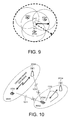
- FIG. 10 illustrates an example of spatial re-use with beamformed transmission.
- FIG. 11 illustrates an example of spatial re-use with different channel width.
- FIG. 12 is a flow chart of a method of spatial re-use with TPC and adaptive CCA in accordance with one novel aspect.
- FIG. 13 illustrates an adaptive CCA threshold of a spatial reuse STA based on baseline CCA level and a reference transmit power level.
- FIG. 1 illustrates a wireless network 100 having overlapping basic service set (OBSS) with spatial re-use in accordance with one novel aspect.
- Wireless network 100 comprises a plurality of wireless stations 111 (STA 1 ), 112 (STA 2 ), 113 (STA 3 ), and 114 (STA 4 ).
- Each station can be an access point station (AP-STA), or a non-AP-STA.
- STA 1 and STA 2 belong to a first BSS 1 having STA 2 as an access point (AP), and STA 3 and STA 4 belong to a second BSS 2 having STA 4 as an access point (AP).
- BSS 1 and BSS 2 are overlapping BSS (OBSS) with overlapping coverages.
- STA 1 and STA 2 have gained the access to the wireless medium and have ongoing frame exchange between them. Meanwhile, STA 3 is trying to initiate a frame exchange with STA 4 .
- an enhanced distributed channel access protocol is used as a channel contention procedure for wireless devices to gain access to the shared wireless medium, e.g., to obtain a transmitting opportunity (TXOP) for transmitting radio signals onto the shared wireless medium.
- TXOP transmitting opportunity
- the primary channel is BUSY of one of the predefined conditions is met based on Clear Channel Assessment (CCA) sensitivity levels.
- CCA Clear Channel Assessment
- the transmit channel width is selected based on the secondary channel CCA during an interval (PIFS) immediately preceding the start of TXOP.
- the secondary channel is BUSY if one of the predefined conditions is met based on CCA levels.
- IEEE 802.11ac is a wireless networking standard in the 802.11 family providing high-throughput WLANs on the 5 GHz band.
- the High Efficiency WLAN study group (HEW SG) is a study group within IEEE 802.11 working group that will consider the improvement of spectrum efficiency to enhance the system throughput in high-density scenarios of wireless devices. Because of HEW SG, TGax (an IEEE task group) was formed and tasked to work on IEEE 802.11ax standard that will become a successor to IEEE 802.11ac.
- a solution based on transmit power control (TPC) and adaptive CCA level is provided 1) to increase the spatial re-use without causing collision; 2) to maintain fairness between stations in different BSSs; 3) to maintain fairness between HEW stations and legacy stations; and 4) to maintain power efficiency.
- TPC transmit power control
- adaptive CCA level is provided 1) to increase the spatial re-use without causing collision; 2) to maintain fairness between stations in different BSSs; 3) to maintain fairness between HEW stations and legacy stations; and 4) to maintain power efficiency.
- STA 3 if STA 3 wants to establish a link with STA 4 without interfering with STA 1 /STA 2 with spatial re-use, it requires several pre-conditions: 1) STA 3 needs to identify whether the STA 1 /STA 2 link is an inter-BSS link or an intra-BSS link; 2) STA 3 should not cause interference to STA 1 and STA 2 , e.g., radio signal 121 does not interfere STA 1 and radio signal 122 does not interfere STA 2 ; and 3) STA 4 should not cause interference to STA 1 and STA 2 , e.g., radio signal 123 does not interfere STA 1 and radio signal 124 does not interfere STA 4 .
- pre-condition 3 might not be satisfied.
- STA 4 transmission results in collision it is called the hidden node problem. Skipping the pre-condition 3) results in simpler procedure at the expense of higher chance of collision.
- pre-condition 2) might only be partially satisfied, i.e., STA 3 might cause interference to one of STA 1 or STA 2 .
- TPC and adaptive CCA is applied by STA 3 and/or STA 4 to satisfy the preconditions for spatial re-use and thereby increasing network throughput.
- FIG. 2 is a simplified block diagram of an initiating device 201 and a responding device 211 in a wireless network 200 in accordance with one novel aspect.
- Initiating device 201 comprises memory 202 , a processor 203 , a control and configuration module 204 , a power controller 205 , an EDCA module 206 , a spatial re-use detection module 207 , and a transceiver 208 coupled to antenna 209 .
- responding device 211 comprises memory 212 , a processor 213 , a control and configuration module 214 , a power controller 215 , an EDCA module 216 , a spatial re-use detection module 217 , and a transceiver 218 coupled to antenna 219 .
- the transceiver converts received baseband signals from the processor to RF signals and sends out to the antenna.
- the processor processes the received baseband signals from the transceiver and invoke different functional modules to be configured to perform various features supported by the wireless devices.
- the different modules are functional modules that can be implemented in software, firmware, hardware, or any combination thereof.
- the function modules when executed by processors 203 and 213 (via program instructions 209 and 219 contained in memory 202 and 212 ), interwork with each other to allow the wireless devices to perform channel access with spatial re-use.
- the spatial re-use detection module observe the wireless medium to confirm that it is allowed to start a spatial re-use frame exchange 231 , the EDCA module contends the wireless medium for spatial re-use with other STAs through a random backoff EDCA procedure, the control and configuration module performs various control and configuration functionalities, and the power control module determines and controls a transmit (TX) power level (or TX spectral power density) such that spatial re-use frame exchange 231 does not cause collision in the network.
- TX transmit
- FIG. 3 illustrates a method flow of a wireless device performing spatial re-use frame exchange in a wireless network.
- the wireless network comprises a plurality of stations STA 1 , STA 2 , STA 3 , and STA 4 .
- STA 1 and STA 2 have gained a TXOP to access the wireless medium and have ongoing frame exchange between them.
- STA 3 is trying to initiate a frame exchange with STA 4 by exploiting spatial re-use of the wireless medium.
- STA 3 performs spatial observation of the wireless medium and update its database for spatial re-use purpose. Note that spatial observation is an optional step and can occur during a long-term or a short-term moving observation window before the actual spatial re-use frame exchange.
- STA 3 performs spatial re-use detection and observes the on-going frame exchange in the wireless medium to confirm whether STA 3 is allowed to start a spatial re-use frame exchange.
- STA 3 applies TPC with adaptive CCA level in determining its TX power level.
- STA 3 decides whether its TX power level is sufficient to close the link with STA 4 based on its prior experience or observation. If there is not sufficient margin to close the link, STA 3 abandons its attempt for spatial re-use based on current spatial detection. If STA 3 has sufficient link margin, it then raises its CCA level based on the observed signal (power density) level from STA 1 and STA 2 such that it can perform EDCA backoff procedure.
- step 333 STA 3 performs an EDCA backoff procedure to contend the wireless medium with other spatial re-use STAs for spatial re-use frame exchange with STA 4 .
- step 334 STA 3 gains a spatial re-use TXOP and starts frame exchange with STA 4 .
- STA 4 is engaging in spatial observation when it receives a spatial re-use packet from STA 3 .
- STA 4 applies TPC in determining its TX power level when it transmits a response to STA 3 .
- FIG. 4 illustrates a preferred embodiment of transmit power control (TPC) and adaptive CCA level for spatial re-use with HEW stations.
- STA 1 and STA 2 have ongoing frame exchange in BSS 1
- STA 3 applies TPC to ensure that any spatial re-use frame exchange in BSS 2 will not causing interference to STA 1 and to STA 2 .
- STA 1 and STA 2 signal their transmit power level (TX-PWR_STA 1 and TX-PWR_STA 2 ) and their received signal strength indicator (RSSI) from the peer. Signaling TX-PWR allows a receiver (e.g., STA 3 ) to determine the pathloss.
- the pathloss between STA 1 and STA 3 TX-PWR_STA 1 ⁇ RSSI (by STA 3 from STA 1 ).
- the pathloss between STA 2 and STA 3 TX-PWR_STA 2 ⁇ RSSI (by STA 3 from STA 2 ).
- STA 3 can then determine its own TX power level (TPC) based on the following equations, and STA 3 should select the lower TX power level between TPC 1 and TPC 2 such that STA 3 would not cause interference to both STA 1 and STA 2 .
- TPC TX power level
- TPC 1 or TPC 2 only one of the two in-equality (TPC 1 or TPC 2 ) needs to be satisfied if the STA 3 only observes transmission of one of STA 1 or STA 2 .
- STA 3 Since STA 3 power arrives at STA 1 /STA 2 below its peer RSSI from STA 2 /STA 1 minus fixed margin, it does not cause interference to STA 1 /STA 2 .
- the fixed margin e.g., 20 dB, is required for signal to noise ratio (SNR) for operating certain MCS (Modulation and coding scheme). If STA 3 cannot close the link with STA 4 , then STA 3 should abandon its transmission. In some situations, STA 3 does not receive either STA 1 or STA 2 signal. In this case, only one transmit power level (TPC 1 or TPC 2 ) obtained from the received signal is used.
- SNR signal to noise ratio
- STA 1 and STA 2 might be operating at certain interference level from other links (which is above the noise level).
- a more precise estimation of the TX power level for STA 3 can be obtained if STA 1 and STA 2 directly signal their received interference level, or their adjusted CCA level.
- STA 3 can then determine its TX power level based on the following equations for STA 1 and STA 2 respectively and select the lower TX power level between TPC 1 and TPC 2 such that STA 3 would not cause interference to both STA 1 and STA 2 .
- TPC1 ⁇ Pathloss STA1-3 ⁇ received interference level_STA1 ⁇ error margin
- TPC2 ⁇ Pathloss (STA2-3) ⁇ received interference level_STA2 ⁇ error margin or TPC1 ⁇ Pathloss (STA1-3) ⁇ adjusted CCA level_STA1 ⁇ error margin
- TPC2 ⁇ Pathloss (STA2-3) ⁇ adjusted CCA level_STA2 ⁇ error margin TPC1 ⁇ Pathloss (STA1-3) ⁇ received interference level_STA1 ⁇ error margin
- TPC2 ⁇ Pathloss (STA2-3) ⁇ adjusted CCA level_STA2 ⁇ error margin TPC1 ⁇ Pathloss (STA1-3) ⁇ received interference level_STA1 ⁇ error margin
- TPC2 ⁇ Pathloss (STA2-3) ⁇ adjusted CCA level_STA2 ⁇ error margin TPC1 ⁇ Pathloss (STA1-3) ⁇
- TPC 1 or TPC 2 only one of the two in-equality (TPC 1 or TPC 2 ) needs to be satisfied if the STA 3 only observes transmission of one of STA 1 or STA 2 .
- the error margin e.g., 5 dB, is applied to accommodate error.
- the adjusted CCA level of STA 3 is equal to the received interference (+noise) level at STA 3 . If STA 3 cannot close the link with STA 4 , then STA 3 should abandon its transmission. In some situations, the STA 3 does not receive either STA 1 or STA 2 signal. In this case, only one transmit power level (TPC 1 or TPC 2 ) obtained from the received signal is used.
- STA 3 In addition to transmit power level (TX-PWR), RSSI from peer, received interference level, adjusted CCA level, additional information is required by STA 3 from STA 1 and STA 2 for spatial re-use purpose.
- STA 3 needs to identify whether the STA 1 /STA 2 link is an inter-BSS link or an intra-BSS link. In order to do that, STA 1 and STA 2 should signal their BSS color, or TX IDs and RX IDs.
- a BSS color is a shortened indication (e.g., a 3-5 bits indication) of BSS ID, which is chosen by an AP based on its observation of BSS colors of overlapping neighbor BSSs.
- STA 3 needs to know the remaining TXOP duration of the ongoing STA 1 -STA 2 frame exchange so that STA 3 can gain a spatial re-use TXOP that is fair to other legacy STAs. Further details of the spatial re-use TXOP duration will be explained later with respect to FIG. 8 .
- the spatial re-use STAs calculate space loss to STA 1 and STA 2 and adjust their transmit power to be below the received interference-margin of STA 1 and STA 2 to avoid collision.
- TPC and adaptive CCA can avoid the collision during spatial re-use.
- spatial re-use STAs do not have the information to adjust their transmit power level. This is because legacy STAs do not signal their transmit power and received interference, CCA, or RSSI from peer. Therefore, a different TPC should be used in a mixed environment with legacy STAs.
- FIG. 5 illustrates another embodiment of transmit power control and adaptive CCA level based on RSSI for spatial re-use with legacy stations.
- legacy STA 1 and STA 2 have ongoing frame exchange, and HEW STA 3 applies TPC to ensure that any spatial re-use frame exchange will not causing interference to STA 1 and to STA 2 .
- STA 1 and STA 2 in FIG. 5 are legacy STAs, they do not signal their TX-PWR, another TPC is proposed for STA 3 that is based on the RSSI and signal bandwidth from STA 1 and STA 2 .
- the received interference level is at the CCA of the legacy STA, and 2) the transmit power (i.e., TX-PWR_Ref) is the same for all STAs, with a margin to accommodate the TX power level differences.
- the transmit power i.e., TX-PWR_Ref
- all non-AP STAs have the same transmit power level and all AP STAs have the same transmit power level where AP's transmit power level and non-AP STA's transmit power level differ by a fixed value. As illustrated in FIG.
- a reference transmit power level TX-PWR_Ref and the baseline CCA level at CCA_baseline are defined.
- STA 3 intending to access the medium, receives a signal from STA 1 with a power level RX-PWR STA1 exceeding CCA and/or receives a signal from STA 2 with a power level RX-PWR STA2 exceeding CCA.
- STA 3 is then allowed to access the medium in concurrent with STA 1 's transmission. If the adjusted transmit power is not enough to close the link, then STA 3 abandons the transmission. Note that the margin is used to accommodate differences in transmit power from TX-PWR_Ref in STA 1 and STA 2 , since STA 1 and/or STA 2 might not signal their transmit power. By reducing the transmit power below (TX-PWR_Ref ⁇ margin), the STA 3 reduces the chance of causing interference to the transmitting STA (STA 1 ) and achieves the spatial re-use.
- FIG. 6 illustrates one embodiment of spatial re-use with excessive margin in a wireless network 600 .
- STA 1 and STA 2 have ongoing frame exchange, and STA 3 is trying to initiate spatial re-use frame exchange with other STAs.
- STA 1 has excess margin M_rx in the received link.
- the excess margin is defined as the difference between the received SNR and the required SNR when highest MCS is being used.
- STA 1 can allow other OBSS spatial re-use STAs (e.g., STA 3 ) more room for spatial re-use by: 1) signaling M_rx to other spatial re-use STAs, which allows OBSS STAs to have higher spatial re-use TPC; 2) lowering its own TPC to reduce interference to OBSS STAs, and 3) signaling an artificially raised received interference level or adjusted CCA to a higher level corresponding to M_rx, which allows OBSS STAs to have higher spatial re-use TPC.
- the spatial re-use STA 4 in response to STA 3 signal should adjust its transmit power based on information received or received RSSI in the frame exchange signals of STA 1 and STA 2 immediately prior to STA 3 's transmission of spatial re-use signal.
- FIG. 7 illustrates a processing flow of spatial re-use in accordance with one novel aspect.
- spatial re-use STA 3 performs a four-step spatial re-use procedure to be able to have spatial re-use frame exchange while OBSS STA 1 and STA 2 have ongoing frame exchange.
- the four steps are spatial observation, spatial re-use detection, spatial contention, and spatial re-use frame exchange.
- STA 3 observes the medium and constantly updates its database prior to frame exchange.
- the database information obtained from information signaled by STAs, observed RSSIs, BSS color, etc.
- the spatial observation allows STA 3 to form a decision of what transmit power level to use during spatial re-use, and to determine whether the recipient STA is nearby or not when a nearby STA sends a frame. Note the TPC based on the long-term spatial observation is overly conservative since most of neighbor STAs observed might not be active during the spatial re-use frame exchange.
- STA 3 wants to initiate a frame exchange and therefore detects ongoing frame exchange in the medium to confirm that it is allowed to start a spatial re-use frame exchange. Since a pair of STAs (STA 1 and STA 2 ) are doing frame exchange, both STA 1 and STA 2 need to be taken into considerations during the spatial re-use detection. In order for STA 3 not to interfere with both STA 1 and STA 2 , STA 3 observes the medium and performs spatial re-use detection. Spatial re-use detection mandates STA 3 to observe the medium for a duration (e.g., T 2 ) during which both STA 1 and STA 2 transmit PPDU.
- a duration e.g., T 2
- STA 3 determines a first transmit power that would not cause interference to STA 1 , a second transmit power that would not cause interference to STA 2 , and then selects the lower transmit power so that the spatial re-use frame exchange would not interfere both STA 1 and STA 2 .
- STA 3 might only receive signal from one of STA 1 or STA 2 during spatial detection.
- STA 3 should also collects spatial re-use information such as BSS color, received interference level or received RSSI or adjusted CCA, remaining TXOP duration from STA 1 and STA 2 .
- a spatial re-use STA 4 should also observes the medium and the spatial re-use information collected immediately prior to receiving a signal from STA 3 is used to determine its transmit power level.
- STA 3 contends the medium for spatial re-use with other STAs. After spatial re-use detection is completed, STA 3 decides whether to initiate a spatial re-use frame exchange based on if it can close the link. STA 3 shall perform a backoff procedure (e.g., EDCA procedure) during time T 3 to prevent collision with other spatial re-use stations. STA 3 spatial re-use backoff procedure should be independent from non-spatial-reuse backoff procedures that are not invoked by the adaptive CCA. This is to ensure fairness to legacy STAs, because legacy STAs do not participate in the spatial re-use EDCA.
- EDCA procedure e.g., EDCA procedure
- the spatial re-use EDCA cannot be used to change the back off counter of the EDCA that employs fixed legacy CCA levels. It is important that all spatial re-use STA use the same procedure to determine when to start spatial re-use backoff procedure to ensure all spatial re-use STAs compete equally and avoids collision among the spatial re-use STAs.
- STA 3 starts a spatial re-use frame exchange by transmitting a frame to its intended recipient station (e.g., STA 4 ).
- STA 3 gains spatial re-use TXOP and starts frame exchange with its peer station (e.g., STA 4 ) during time T 4 .
- peer station e.g., STA 4
- STA 3 shall start with a request to send (RTS) transmission to avoid STA 4 interfering with STA 1 /STA 2 or any other OBSS STAs in proximity to STA 4 .
- Legacy STA will not respond with clear to send (CTS) if its NAV is not zero.
- CTS clear to send
- Spatial re-use STA 4 adopts the CCA and TX power level adjustment rules for spatial re-use when it responds to STA 3 .
- STA 4 should determine whether it could respond and adjust its TX power level based on the spatial re-use information it receives during spatial observation of ongoing medium activities prior to STA 3 's transmission, the prior or observed link margin with STA 3 .
- STA 4 determines its TX power level the same way as STA 3 based on its received or observed spatial re-use information.
- FIG. 8 illustrates spatial re-use and corresponding frame exchange with a fair TXOP duration and EDCA rules in a mixed wireless network with both legacy stations and spatial re-use stations.
- AP 1 , STA 1 and STA 2 belong to a first BSS 1
- spatial re-use STA 3 belongs to a second BSS 2 .
- STA 1 and AP 1 engages in an ongoing frame exchange.
- Spatial re-use STA 3 initiates a spatial re-use frame exchange with other stations in BSS 2 (e.g., another STA, STA 4 , not shown).
- STA 2 is a legacy station, and its NAV setting is non-zero from time t 0 to t 1 due to the ongoing frame exchange between STA 1 and AP 1 .
- STA 3 when spatial re-use STA 3 establishes spatial re-use duration from t 3 to t 2 , STA 2 has to reset its NAV from t 1 to t 2 . This results in an unfair advantage of spatial re-use STA 3 over legacy STA 2 since it causes STA 2 to be deferred further.
- the spatial re-use frame exchange duration (TXOP) should be limited to the original NAV setting between STA 1 and AP 1 .
- the spatial re-use transmission shall end before time t 1 so that it will not cause STA 2 NAV to be extended to time t 2 .
- STA 2 can resume medium contention from time t 1 .
- STA 1 and AP 1 can signal the remaining TXOP duration. For example, they signal the remaining duration from a reference time epoch in the packet such as at the end of the preamble or end of the packet transmission.
- STA 3 performs spatial contention so that STA 3 contends the medium and gains a fair spatial re-use duration with TXOP that ends at time t 1 .
- the OBSS non-AP spatial re-use STA or OBSS spatial re-use AP may initiate a spatial re-use exchange after a spatial re-use Backoff.
- the spatial re-use Backoff is initialized with pre-defined EDCA parameters or from the most recently received spatial re-use EDCA parameter set element sent by the AP with which the STA is associated.
- the spatial re-use Backoff is initialized with the spatial re-use EDCA parameters.
- the spatial re-use Backoff function begins or resumes when the spatial detection is performed.
- the spatial re-use Backoff function is independent of all other legacy backoff functions but follows the similar EDCAF backoff procedure.
- An OBSS non-AP spatial re-use STA or OBSS spatial re-use AP that invokes or resumes a spatial re-use Backoff at the confirmation of a spatial re-use condition shall set a spatial re-use timer to NAV or based on spatial re-use information such as received remaining TXOP duration and reset its NAV and suspend EDCAF backoff procedures.
- An OBSS non-AP spatial re-use STA or OBSS spatial re-use AP that initiates a new spatially re-use frame exchange after a spatial re-use Backoff procedure shall start the exchange with RTS/CTS when transmitting to a legacy STA or start with regular frame when transmitting to another spatial re-use STA and shall limit the duration of the exchange such that it ends before the expiry of the spatial re-use timer.
- the STA shall obey the TXOP limit of the AC of the frames transmitted within the spatial re-use frame exchange or the remaining TXOP duration received during spatial detection.
- An STA that transmits a spatial re-use frame exchange may transmit additional spatial re-use frame exchanges by continuing to use the spatial re-use Backoff function until the expiry of the spatial re-use timer. If the ongoing frame exchange transmission is between a pair of STAs within its BSS (with matching BSS color), the STA does not reset its NAV even though the Spatially Re-use conditions are met.
- FIG. 9 illustrates an example of OFDMA operation.
- One mode of Uplink (UL) OFDMA operation starts with AP 1 transmitting a trigger frame and multiple STAs (STA 1 -STA 3 ) transmit UL OFDMA signals which occupy a fraction of the channel bandwidth.
- STAs in response to AP signal, might not perform CCA before their uplink transmission and STAs have high transmit power density (narrow band signal), it is expected that STAs' signals may propagate farther than APs signal. Additionally, STAs' transmission duration can be shorter than TXOP. Therefore, it is more difficult to perform spatial observation or spatial re-use detection for UL OFDMA.
- an OBSS spatial re-use STA can use the aggregate received power and aggregate received interference from these OFDMA STAs to adapt its CCA level and determine its transmit power adjustment.
- an OBSS spatial re-use STA can use the max-received power from all the OFDMA STAs to adapt its CCA and adjust its TX power to be below minimum received interference of all OFDMA STAs.
- no spatial re-use is applied if UL OFDMA is used.
- AP-to-AP coordination is required for UL OFDMA to mitigate OBSS interference based on some pre-determined procedure.
- FIG. 10 illustrates an example of spatial re-use with beamformed transmission.
- STA with spatial reciprocity it can employ beamforming during spatial re-use detection.
- Spatial reciprocity is a device capability of transmitting and receiving with the same antenna pattern that could be synthesized with multiple antennas.
- STA 1 and STA 2 engages in an ongoing frame exchange in BSS 1 .
- Spatial re-use STA 3 can perform spatial detection under beamformed condition.
- proper beamforming antenna setting 1013 can be used to suppress the received power from STA 1 and/or STA 2 or to enhance link margin with STA 4 during spatial detection and spatial re-use frame exchange.
- spatial re-use STA 3 initiates a spatial re-use frame exchange with STA 4 in BSS 2 .
- STA 3 performs a spatial detection with radio signals 1011 and 1012 from STA 1 and STA 2 via spatially reciprocal beamforming. If STA 3 cannot hear from STA 1 and STA 2 using a beamformed antenna pattern 1013 for receiving, then the radio signals transmitted from the spatially reciprocal device STA 3 do not interfere STA 1 and STA 2 if STA 3 applies with the same beamformed antenna pattern 1013 .
- the same adaptive CCA and transmit power adjustment procedure can be applied to the spatially reciprocal beamforming STAs for spatial re-use.
- Proper beamforming in conjunction with the proposed TPC and adaptive CCA can enhance the spatial re-use by suppressing STA 1 and/or STA 2 signal level and/or enhancing link robustness and quality between STA 3 and STA 4 .
- FIG. 11 illustrates an example of spatial re-use with different channel widths.
- the signal propagation range is determined by the spectral density (power/Hz) instead of the signal power level.
- the baseline (primary channel) CCA levels are based on equal spectral density for all RX channel widths.
- the CCA level/channel width (in unit of 20 MHz) is equal to ⁇ 82 dBm, ⁇ 79 dBm, ⁇ 76 dBm, ⁇ 73 dBm for any 20 MHz, 40 MHz, 80 MHz, and 160 MHz RX channels, respectively.
- the TX spectral density is not the same for all TX channel widths.
- the TX spectral density of a narrower TX channel is typically higher than the TX spectral density of a wider TX channel, e.g., TX_PWR/20M>TX_PWR/40M>TX_PWR/80M>TX_PWR/160M.
- TX_PWR/20M>TX_PWR/40M>TX_PWR/80M>TX_PWR/160M e.g., TX_PWR/20M>TX_PWR/40M>TX_PWR/80M>TX_PWR/160M.
- these transmit power level is determined based on the received power density level (received RSSI scaled by signal bandwidth from legacy STAs) or the received interference power density level or adjusted CCA level scaled by the signal bandwidth received from spatial re-use STA. Additionally, the signaled TX power level should be adjusted by bandwidth. This resolves the issue of narrower width transmission interfering or deferring a wider width transmission. The likelihood of the wider channel transmission is increased.
- an STA follow the following modified EDCA channel access: a) Transmit a 160 MHz or 80+80 MHz mask PPDU at the power level P if the secondary channel, the secondary 40 MHz channel and the secondary 80 MHz channel were idle during an interval of PIFS immediately preceding the start of the TXOP; b) Transmit an 80 MHz mask PPDU at the power level P-3 dB on the primary 80 MHz channel if the secondary channel and the secondary 40 MHz channel were idle during an interval of PIFS immediately preceding the start of the TXOP; c) Transmit a 40 MHz mask PPDU at a power level P-6 dB on the primary 40 MHz channel if the secondary channel was idle during an interval of PIFS immediately preceding the start of the TXOP; d) Transmit a 20 MHz mask PPDU at a power level P-9 dB on the primary
- FIG. 12 is a flow chart of a method of spatial re-use with TPC and adaptive CCA in accordance with one novel aspect.
- a spatial re-use station detects spatial re-use information associated with other peer stations belong to an inter-BSS or overlapping BSS.
- the inter-BSS peer stations engage an ongoing frame exchange.
- the spatial re-use information comprises a TX spectral density (power/Hz) and received signal or interference information of each inter-BSS peer station.
- the spatial re-use STA determines a TX spectral density based on the detected spatial re-use information.
- the spatial re-use STA contends the medium for spatial re-use transmission opportunity (TXOP) with an intra-BSS peer station.
- TXOP spatial re-use transmission opportunity
- the spatial re-use STA starts a spatial re-use frame exchange with the intra-BSS peer station using the determined TX spectral density such that the spatial re-use frame exchange does not interfere with the ongoing frame exchange.
- the spatial re-use STA adapts its CCA level to spatially reuse the medium without causing collision and interference to OBSS stations and thus increases network throughput.
- a reference transmit power level TX-PWR_Ref and the baseline CCA level at CCA_baseline are defined.
- STA 3 intending to access the medium, receives a signal from STA 1 with a power level RX-PWR STA1 exceeding CCA and/or receives a signal from STA 2 with a power level RX-PWR STA2 exceeding CCA.
- the above description is a general case of two stations (STA 1 and STA 2 ).
- FIG. 13 illustrates an adaptive CCA threshold of a spatial reuse STA based on baseline CCA level (Baseline CCA) and a reference transmit power level (Ref_PWR Level ).
- the baseline CCA level is ⁇ 72 dBm (20 MHz)
- the reference transmit power level is 23 dBm.
- CCA Threshold max ⁇ ⁇ Baseline ⁇ ⁇ CCA min ⁇ ⁇ Upper ⁇ ⁇ Limit Baseline ⁇ ⁇ CCA + ( Ref PWR Level - TX PWR ) ⁇ ⁇
- Spatial re-use by STA 3 may cause interference to the ongoing frame exchange between STA 1 and STA 2 .
- STA 3 During spatial re-use contention, if STA 3 observes the medium energy level increases (due to another STA initiating a spatial re-use transmission), STA 3 should abandon the spatial re-use attempt. This limit the number of spatial re-use transmission, which can significantly increase interference to STA 1 and STA 2 .
- the responding station sends a response to inhibit the spatial re-use attempt by STA 3 .
- the response comprises a flag in a header indicating that spatial re-use is disallowed and thus inhibiting the spatial re-use attempt by the initiating station STA 3 .
- an initiating station may also set the spatial re-use inhibit flag in a frame header to prevent too many stations from transmitting spatial re-use.
Abstract
Description
Pathloss (STA1-3)=TX-PWR_STA1−RSSI (by STA3 from STA1);
Pathloss (STA2-3)=TX-PWR_STA2−RSSI (by STA3 from STA2); and
TPC1−pathloss(STA1-3)<RSSI (by STA1 from STA2)−Fixed Margin;
TPC2−pathloss(STA2-3)<RSSI (by STA2 from STA1)−Fixed Margin.
In an embodiment, only one of the two in-equality (TPC1 or TPC2) needs to be satisfied if the STA3 only observes transmission of one of STA1 or STA2.
TPC1−Pathloss (STA1-3)<received interference level_STA1−error margin;
TPC2−Pathloss (STA2-3)<received interference level_STA2−error margin; or
TPC1−Pathloss (STA1-3)<adjusted CCA level_STA1−error margin;
TPC2−Pathloss (STA2-3)<adjusted CCA level_STA2−error margin.
Claims (27)
Priority Applications (3)
| Application Number | Priority Date | Filing Date | Title |
|---|---|---|---|
| US15/019,849 US9820162B2 (en) | 2014-01-24 | 2016-02-09 | Adaptive CCA and TX power level adjustment for dense deployment of wireless networks |
| EP17155030.4A EP3206444A1 (en) | 2016-02-09 | 2017-02-07 | Adaptive cca and tx power level adjustment for dense deployment of wireless networks |
| DE202017006909.1U DE202017006909U1 (en) | 2014-01-24 | 2017-02-07 | Adaptive CCA and TX power level adjustment for dense deployment of wireless networks |
Applications Claiming Priority (7)
| Application Number | Priority Date | Filing Date | Title |
|---|---|---|---|
| US201461931080P | 2014-01-24 | 2014-01-24 | |
| US201461932324P | 2014-01-28 | 2014-01-28 | |
| US201461937719P | 2014-02-10 | 2014-02-10 | |
| PCT/US2015/012556 WO2015112780A1 (en) | 2014-01-24 | 2015-01-23 | Adaptive cca and tx power level adjustment for dense deployment of wireless networks |
| US201562114272P | 2015-02-10 | 2015-02-10 | |
| US201562116703P | 2015-02-16 | 2015-02-16 | |
| US15/019,849 US9820162B2 (en) | 2014-01-24 | 2016-02-09 | Adaptive CCA and TX power level adjustment for dense deployment of wireless networks |
Related Parent Applications (1)
| Application Number | Title | Priority Date | Filing Date |
|---|---|---|---|
| PCT/US2015/012556 Continuation-In-Part WO2015112780A1 (en) | 2014-01-24 | 2015-01-23 | Adaptive cca and tx power level adjustment for dense deployment of wireless networks |
Publications (2)
| Publication Number | Publication Date |
|---|---|
| US20160174079A1 US20160174079A1 (en) | 2016-06-16 |
| US9820162B2 true US9820162B2 (en) | 2017-11-14 |
Family
ID=56112499
Family Applications (1)
| Application Number | Title | Priority Date | Filing Date |
|---|---|---|---|
| US15/019,849 Active 2035-04-27 US9820162B2 (en) | 2014-01-24 | 2016-02-09 | Adaptive CCA and TX power level adjustment for dense deployment of wireless networks |
Country Status (2)
| Country | Link |
|---|---|
| US (1) | US9820162B2 (en) |
| DE (1) | DE202017006909U1 (en) |
Cited By (7)
| Publication number | Priority date | Publication date | Assignee | Title |
|---|---|---|---|---|
| US20150296370A1 (en) * | 2014-04-09 | 2015-10-15 | Newracom, Inc. | Operation method of station based on station density in wireless local area network |
| US10694452B2 (en) | 2018-08-08 | 2020-06-23 | Hewlett Packard Enterprise Development Lp | Foreign AP handling in 802.11AX by color matching |
| US10848254B2 (en) | 2018-09-07 | 2020-11-24 | Hewlett Packard Enterprise Development Lp | Enhanced channel access in 802.11ax using SRG for foreign APs |
| US10869280B2 (en) | 2018-09-02 | 2020-12-15 | Cisco Technology, Inc. | Managing coverage areas provided by densely-arranged wireless endpoint devices with directional antennas |
| US11381366B2 (en) | 2018-11-16 | 2022-07-05 | Samsung Electronics Co., Ltd. | Wireless communication devices for transmitting data using spatial reuse and data communication methods using the same |
| US11432247B2 (en) | 2019-04-22 | 2022-08-30 | Cypress Semiconductor Corporation | Methods, systems and devices for varying wireless transmit power based on path loss information |
| US20230247515A1 (en) * | 2006-03-02 | 2023-08-03 | Tango Networks, Inc. | Calling line/name identification of enterprise subscribers in mobile calls |
Families Citing this family (35)
| Publication number | Priority date | Publication date | Assignee | Title |
|---|---|---|---|---|
| WO2015120579A1 (en) * | 2014-02-11 | 2015-08-20 | 华为技术有限公司 | Data sending method and apparatus |
| EP3123804B1 (en) * | 2014-03-28 | 2019-12-04 | Intel IP Corporation | Mechanisms of virtual clear channel assessment for wi-fi devices |
| EP3139690B1 (en) * | 2014-05-01 | 2023-06-14 | LG Electronics Inc. | Method for improving space reuse rate in wireless lan system and apparatus for same |
| US10743289B2 (en) * | 2014-05-26 | 2020-08-11 | Wilus Institute Of Standards And Technology Inc. | Wireless communication method and wireless communication device for broadband link configuration |
| CN106538029B (en) | 2014-06-27 | 2020-10-16 | 泰科弗勒克斯公司 | Method and apparatus for transmitting data units |
| WO2015198157A2 (en) * | 2014-06-27 | 2015-12-30 | Tech Flux, Ltd. | Method and device for transmitting data |
| US10064066B2 (en) * | 2014-10-20 | 2018-08-28 | Lg Electronics Inc. | Method for transmitting and receiving wireless signal in wireless communication system and apparatus therefor |
| WO2016068624A2 (en) | 2014-10-29 | 2016-05-06 | 주식회사 윌러스표준기술연구소 | Wireless communication method and wireless communication device for configuring broadband link |
| US9942901B2 (en) * | 2014-11-07 | 2018-04-10 | Cisco Technology, Inc. | Minimizing interference in wireless communication |
| US10021721B2 (en) * | 2015-01-28 | 2018-07-10 | Newracom, Inc. | Transmission control method |
| WO2016154818A1 (en) * | 2015-03-27 | 2016-10-06 | 华为技术有限公司 | Multi-site access method, apparatus and system |
| WO2016176110A1 (en) * | 2015-04-28 | 2016-11-03 | Interdigital Patent Holdings, Inc. | Methods, apparatus and systems for procedures for carrier sense multiple access and spatial reuse in sub-channelized wireless local area networks (wlans) |
| US10135651B2 (en) * | 2015-06-24 | 2018-11-20 | Newracom, Inc. | Enhanced clear channel assessment |
| WO2017033790A1 (en) * | 2015-08-21 | 2017-03-02 | 日本電信電話株式会社 | Radio communication system and radio communication method |
| US10375702B2 (en) | 2015-09-18 | 2019-08-06 | Mediatek Inc. | Method and apparatus for guided adaptive spatial reuse in wireless communication |
| US10206227B2 (en) | 2015-09-22 | 2019-02-12 | Mediatek Inc. | Device and method of setting clear channel assessment threshold |
| US10075976B2 (en) | 2015-11-06 | 2018-09-11 | Cisco Technology, Inc. | Enhanced clear channel assessment |
| US20170223710A1 (en) * | 2016-01-29 | 2017-08-03 | Laurent Cariou | Setting parameters for joint overlapping basic service set packet detect level and transmit power |
| EP3429301B1 (en) * | 2016-03-08 | 2021-12-22 | Sony Group Corporation | Wireless communication device and wireless communication method |
| US10764877B2 (en) | 2016-05-06 | 2020-09-01 | Qualcomm Incorporated | Trigger frame in wireless local area network |
| WO2017195458A1 (en) * | 2016-05-13 | 2017-11-16 | パナソニック インテレクチュアル プロパティ コーポレーション オブ アメリカ | Wireless station and communication method |
| US11438778B2 (en) * | 2016-09-26 | 2022-09-06 | Sony Corporation | Access point device, station device, wireless control method, communication control method, and program |
| EP3520334B1 (en) * | 2016-09-30 | 2022-02-16 | ZTE Corporation | Techniques of improving edca mechanism in spatial reuse |
| US20180176789A1 (en) * | 2016-12-16 | 2018-06-21 | Avago Technologies General Ip( Singapore) Pte Ltd. | Spatial reuse ppdu indication |
| RU2752237C2 (en) * | 2016-12-20 | 2021-07-23 | Сони Корпорейшн | Communication device and method for communication |
| US10123358B2 (en) * | 2016-12-22 | 2018-11-06 | Qualcomm Incorporated | Priority management for new radio-spectrum sharing (NR-SS) |
| US10236998B1 (en) | 2017-01-18 | 2019-03-19 | Cisco Technology Inc. | Interference-cancellation-based CCA adjustment |
| WO2019013765A1 (en) | 2017-07-11 | 2019-01-17 | Hewlett-Packard Development Company, L.P. | Transmission power adjustments |
| EP3761692A4 (en) * | 2018-02-28 | 2021-04-28 | Panasonic Intellectual Property Corporation of America | Radio communication device and radio communication method |
| CN110536469A (en) | 2018-05-23 | 2019-12-03 | 华为技术有限公司 | The method and apparatus of spatial reuse based on multi-access point AP cooperation |
| KR20200042774A (en) * | 2018-10-16 | 2020-04-24 | 삼성전자주식회사 | Apparatus and method for managing spatial reuse management in wireless local area network system |
| CN112840709B (en) * | 2018-10-23 | 2022-10-11 | 华为技术有限公司 | Uplink power control system and method in communication system with multi-access point coordination |
| CN112584400B (en) * | 2019-09-30 | 2023-08-25 | 瑞昱半导体股份有限公司 | Method and apparatus for spatial reuse enhancement in a multi-station environment |
| US11357047B2 (en) * | 2020-05-13 | 2022-06-07 | Qualcomm Incorporated | Adaptive detection threshold for contention-based channel access |
| US20240031094A1 (en) * | 2022-07-14 | 2024-01-25 | Mediatek Inc. | Method for performing mesh control in wireless communications system, and associated apparatus |
Citations (3)
| Publication number | Priority date | Publication date | Assignee | Title |
|---|---|---|---|---|
| US20030033394A1 (en) | 2001-03-21 | 2003-02-13 | Stine John A. | Access and routing protocol for ad hoc network using synchronous collision resolution and node state dissemination |
| US20080137627A1 (en) | 2006-12-09 | 2008-06-12 | Matthew Fischer | Method and system for coexistence between 20 mhz and 40 mhz overlapping basic service sets (obss) in wireless local area networks |
| WO2015112780A1 (en) | 2014-01-24 | 2015-07-30 | Mediatek Singapore Pte. Ltd. | Adaptive cca and tx power level adjustment for dense deployment of wireless networks |
-
2016
- 2016-02-09 US US15/019,849 patent/US9820162B2/en active Active
-
2017
- 2017-02-07 DE DE202017006909.1U patent/DE202017006909U1/en active Active
Patent Citations (3)
| Publication number | Priority date | Publication date | Assignee | Title |
|---|---|---|---|---|
| US20030033394A1 (en) | 2001-03-21 | 2003-02-13 | Stine John A. | Access and routing protocol for ad hoc network using synchronous collision resolution and node state dissemination |
| US20080137627A1 (en) | 2006-12-09 | 2008-06-12 | Matthew Fischer | Method and system for coexistence between 20 mhz and 40 mhz overlapping basic service sets (obss) in wireless local area networks |
| WO2015112780A1 (en) | 2014-01-24 | 2015-07-30 | Mediatek Singapore Pte. Ltd. | Adaptive cca and tx power level adjustment for dense deployment of wireless networks |
Non-Patent Citations (2)
| Title |
|---|
| EPO, Search Report for the EP patent application 17155030.4 dated Jun. 2, 2017 (7 pages). |
| International Search Report and Written Opinion of International Search Authority for PCT/US 15/12556 dated Apr. 17, 2015 (6 pages). |
Cited By (7)
| Publication number | Priority date | Publication date | Assignee | Title |
|---|---|---|---|---|
| US20230247515A1 (en) * | 2006-03-02 | 2023-08-03 | Tango Networks, Inc. | Calling line/name identification of enterprise subscribers in mobile calls |
| US20150296370A1 (en) * | 2014-04-09 | 2015-10-15 | Newracom, Inc. | Operation method of station based on station density in wireless local area network |
| US10694452B2 (en) | 2018-08-08 | 2020-06-23 | Hewlett Packard Enterprise Development Lp | Foreign AP handling in 802.11AX by color matching |
| US10869280B2 (en) | 2018-09-02 | 2020-12-15 | Cisco Technology, Inc. | Managing coverage areas provided by densely-arranged wireless endpoint devices with directional antennas |
| US10848254B2 (en) | 2018-09-07 | 2020-11-24 | Hewlett Packard Enterprise Development Lp | Enhanced channel access in 802.11ax using SRG for foreign APs |
| US11381366B2 (en) | 2018-11-16 | 2022-07-05 | Samsung Electronics Co., Ltd. | Wireless communication devices for transmitting data using spatial reuse and data communication methods using the same |
| US11432247B2 (en) | 2019-04-22 | 2022-08-30 | Cypress Semiconductor Corporation | Methods, systems and devices for varying wireless transmit power based on path loss information |
Also Published As
| Publication number | Publication date |
|---|---|
| US20160174079A1 (en) | 2016-06-16 |
| DE202017006909U1 (en) | 2018-10-24 |
Similar Documents
| Publication | Publication Date | Title |
|---|---|---|
| US9820162B2 (en) | Adaptive CCA and TX power level adjustment for dense deployment of wireless networks | |
| US9749967B2 (en) | Spatial reuse parameters for opportunistic adaptive TPC and CCA | |
| WO2015112780A1 (en) | Adaptive cca and tx power level adjustment for dense deployment of wireless networks | |
| US9673956B2 (en) | Prioritized channel access schemes with spatial reuse consideration | |
| CN110024338B (en) | Techniques to improve EDCA mechanisms in spatial multiplexing | |
| US10178686B2 (en) | Increased network throughput with CCA level enhancement | |
| KR101931703B1 (en) | Method and apparatus for transmitting frame in wireless local area network | |
| KR100603561B1 (en) | System of wireless local area network based on transmit power control and method thereof | |
| US9992797B2 (en) | Wide bandwidth favored channel access methods in wireless local area networks | |
| US10516457B2 (en) | Beamforming enhancements for spatial reuse in wireless networks | |
| US9942857B2 (en) | Method for transmitting and receiving interference control signals based on power information, and apparatus therefor | |
| US20170079068A1 (en) | Fairness In Wireless Networks With Adaptive Clear Channel Assessment Thresholds | |
| US10362586B2 (en) | System and method for spatial reuse in directional random access | |
| RU2681350C1 (en) | Station, access point and implemented wireless transfer treatment methods in a wireless communication network | |
| EP3014795B1 (en) | Beamforming enhancements for spatial reuse in wireless networks | |
| US20160149676A1 (en) | Network Allocation Vector Improvement for Wireless Networks | |
| WO2018083860A1 (en) | Communication device and communication method | |
| US20220232580A1 (en) | User Device and Method with Beam Management Enhancements | |
| EP3206444A1 (en) | Adaptive cca and tx power level adjustment for dense deployment of wireless networks | |
| CN117939607A (en) | Controlling transmit power across a Basic Service Set (BSS) |
Legal Events
| Date | Code | Title | Description |
|---|---|---|---|
| AS | Assignment |
Owner name: MEDIATEK SINGAPORE PTE. LTD., SINGAPORE Free format text: ASSIGNMENT OF ASSIGNORS INTEREST;ASSIGNORS:WANG, JAMES JUNE-MING;LIU, JIANHAN;HSU, YUNGPING;SIGNING DATES FROM 20160204 TO 20160207;REEL/FRAME:037760/0845 |
|
| AS | Assignment |
Owner name: MEDIATEK SINGAPORE PTE. LTD., SINGAPORE Free format text: ASSIGNMENT OF ASSIGNORS INTEREST;ASSIGNOR:YU, CHING-HWA;REEL/FRAME:038505/0614 Effective date: 20160506 |
|
| STCF | Information on status: patent grant |
Free format text: PATENTED CASE |
|
| MAFP | Maintenance fee payment |
Free format text: PAYMENT OF MAINTENANCE FEE, 4TH YEAR, LARGE ENTITY (ORIGINAL EVENT CODE: M1551); ENTITY STATUS OF PATENT OWNER: LARGE ENTITY Year of fee payment: 4 |