US9814577B2 - Implantable mesh for musculoskeletal trauma, orthopedic reconstruction and soft tissue repair - Google Patents
Implantable mesh for musculoskeletal trauma, orthopedic reconstruction and soft tissue repair Download PDFInfo
- Publication number
- US9814577B2 US9814577B2 US13/040,072 US201113040072A US9814577B2 US 9814577 B2 US9814577 B2 US 9814577B2 US 201113040072 A US201113040072 A US 201113040072A US 9814577 B2 US9814577 B2 US 9814577B2
- Authority
- US
- United States
- Prior art keywords
- mesh
- strands
- orthopedic implant
- bone plate
- materials
- Prior art date
- Legal status (The legal status is an assumption and is not a legal conclusion. Google has not performed a legal analysis and makes no representation as to the accuracy of the status listed.)
- Active
Links
Images


Classifications
-
- A—HUMAN NECESSITIES
- A61—MEDICAL OR VETERINARY SCIENCE; HYGIENE
- A61F—FILTERS IMPLANTABLE INTO BLOOD VESSELS; PROSTHESES; DEVICES PROVIDING PATENCY TO, OR PREVENTING COLLAPSING OF, TUBULAR STRUCTURES OF THE BODY, e.g. STENTS; ORTHOPAEDIC, NURSING OR CONTRACEPTIVE DEVICES; FOMENTATION; TREATMENT OR PROTECTION OF EYES OR EARS; BANDAGES, DRESSINGS OR ABSORBENT PADS; FIRST-AID KITS
- A61F2/00—Filters implantable into blood vessels; Prostheses, i.e. artificial substitutes or replacements for parts of the body; Appliances for connecting them with the body; Devices providing patency to, or preventing collapsing of, tubular structures of the body, e.g. stents
- A61F2/02—Prostheses implantable into the body
- A61F2/28—Bones
- A61F2/2846—Support means for bone substitute or for bone graft implants, e.g. membranes or plates for covering bone defects
-
- A—HUMAN NECESSITIES
- A61—MEDICAL OR VETERINARY SCIENCE; HYGIENE
- A61B—DIAGNOSIS; SURGERY; IDENTIFICATION
- A61B17/00—Surgical instruments, devices or methods, e.g. tourniquets
- A61B17/56—Surgical instruments or methods for treatment of bones or joints; Devices specially adapted therefor
- A61B17/58—Surgical instruments or methods for treatment of bones or joints; Devices specially adapted therefor for osteosynthesis, e.g. bone plates, screws, setting implements or the like
- A61B17/68—Internal fixation devices, including fasteners and spinal fixators, even if a part thereof projects from the skin
- A61B17/80—Cortical plates, i.e. bone plates; Instruments for holding or positioning cortical plates, or for compressing bones attached to cortical plates
- A61B17/8028—Cushions, i.e. elements forming interface between bone plate and bone
-
- A—HUMAN NECESSITIES
- A61—MEDICAL OR VETERINARY SCIENCE; HYGIENE
- A61B—DIAGNOSIS; SURGERY; IDENTIFICATION
- A61B17/00—Surgical instruments, devices or methods, e.g. tourniquets
- A61B17/56—Surgical instruments or methods for treatment of bones or joints; Devices specially adapted therefor
- A61B17/58—Surgical instruments or methods for treatment of bones or joints; Devices specially adapted therefor for osteosynthesis, e.g. bone plates, screws, setting implements or the like
- A61B17/68—Internal fixation devices, including fasteners and spinal fixators, even if a part thereof projects from the skin
- A61B17/80—Cortical plates, i.e. bone plates; Instruments for holding or positioning cortical plates, or for compressing bones attached to cortical plates
- A61B17/8085—Cortical plates, i.e. bone plates; Instruments for holding or positioning cortical plates, or for compressing bones attached to cortical plates with pliable or malleable elements or having a mesh-like structure, e.g. small strips
-
- A—HUMAN NECESSITIES
- A61—MEDICAL OR VETERINARY SCIENCE; HYGIENE
- A61F—FILTERS IMPLANTABLE INTO BLOOD VESSELS; PROSTHESES; DEVICES PROVIDING PATENCY TO, OR PREVENTING COLLAPSING OF, TUBULAR STRUCTURES OF THE BODY, e.g. STENTS; ORTHOPAEDIC, NURSING OR CONTRACEPTIVE DEVICES; FOMENTATION; TREATMENT OR PROTECTION OF EYES OR EARS; BANDAGES, DRESSINGS OR ABSORBENT PADS; FIRST-AID KITS
- A61F2/00—Filters implantable into blood vessels; Prostheses, i.e. artificial substitutes or replacements for parts of the body; Appliances for connecting them with the body; Devices providing patency to, or preventing collapsing of, tubular structures of the body, e.g. stents
- A61F2/02—Prostheses implantable into the body
- A61F2/30—Joints
- A61F2/32—Joints for the hip
- A61F2/36—Femoral heads ; Femoral endoprostheses
-
- A—HUMAN NECESSITIES
- A61—MEDICAL OR VETERINARY SCIENCE; HYGIENE
- A61F—FILTERS IMPLANTABLE INTO BLOOD VESSELS; PROSTHESES; DEVICES PROVIDING PATENCY TO, OR PREVENTING COLLAPSING OF, TUBULAR STRUCTURES OF THE BODY, e.g. STENTS; ORTHOPAEDIC, NURSING OR CONTRACEPTIVE DEVICES; FOMENTATION; TREATMENT OR PROTECTION OF EYES OR EARS; BANDAGES, DRESSINGS OR ABSORBENT PADS; FIRST-AID KITS
- A61F2/00—Filters implantable into blood vessels; Prostheses, i.e. artificial substitutes or replacements for parts of the body; Appliances for connecting them with the body; Devices providing patency to, or preventing collapsing of, tubular structures of the body, e.g. stents
- A61F2/02—Prostheses implantable into the body
- A61F2/28—Bones
- A61F2002/2817—Bone stimulation by chemical reactions or by osteogenic or biological products for enhancing ossification, e.g. by bone morphogenetic or morphogenic proteins [BMP] or by transforming growth factors [TGF]
-
- A—HUMAN NECESSITIES
- A61—MEDICAL OR VETERINARY SCIENCE; HYGIENE
- A61F—FILTERS IMPLANTABLE INTO BLOOD VESSELS; PROSTHESES; DEVICES PROVIDING PATENCY TO, OR PREVENTING COLLAPSING OF, TUBULAR STRUCTURES OF THE BODY, e.g. STENTS; ORTHOPAEDIC, NURSING OR CONTRACEPTIVE DEVICES; FOMENTATION; TREATMENT OR PROTECTION OF EYES OR EARS; BANDAGES, DRESSINGS OR ABSORBENT PADS; FIRST-AID KITS
- A61F2/00—Filters implantable into blood vessels; Prostheses, i.e. artificial substitutes or replacements for parts of the body; Appliances for connecting them with the body; Devices providing patency to, or preventing collapsing of, tubular structures of the body, e.g. stents
- A61F2/02—Prostheses implantable into the body
- A61F2/30—Joints
- A61F2002/30001—Additional features of subject-matter classified in A61F2/28, A61F2/30 and subgroups thereof
- A61F2002/30003—Material related properties of the prosthesis or of a coating on the prosthesis
- A61F2002/30004—Material related properties of the prosthesis or of a coating on the prosthesis the prosthesis being made from materials having different values of a given property at different locations within the same prosthesis
- A61F2002/30014—Material related properties of the prosthesis or of a coating on the prosthesis the prosthesis being made from materials having different values of a given property at different locations within the same prosthesis differing in elasticity, stiffness or compressibility
-
- A—HUMAN NECESSITIES
- A61—MEDICAL OR VETERINARY SCIENCE; HYGIENE
- A61F—FILTERS IMPLANTABLE INTO BLOOD VESSELS; PROSTHESES; DEVICES PROVIDING PATENCY TO, OR PREVENTING COLLAPSING OF, TUBULAR STRUCTURES OF THE BODY, e.g. STENTS; ORTHOPAEDIC, NURSING OR CONTRACEPTIVE DEVICES; FOMENTATION; TREATMENT OR PROTECTION OF EYES OR EARS; BANDAGES, DRESSINGS OR ABSORBENT PADS; FIRST-AID KITS
- A61F2/00—Filters implantable into blood vessels; Prostheses, i.e. artificial substitutes or replacements for parts of the body; Appliances for connecting them with the body; Devices providing patency to, or preventing collapsing of, tubular structures of the body, e.g. stents
- A61F2/02—Prostheses implantable into the body
- A61F2/30—Joints
- A61F2002/30001—Additional features of subject-matter classified in A61F2/28, A61F2/30 and subgroups thereof
- A61F2002/30003—Material related properties of the prosthesis or of a coating on the prosthesis
- A61F2002/30004—Material related properties of the prosthesis or of a coating on the prosthesis the prosthesis being made from materials having different values of a given property at different locations within the same prosthesis
- A61F2002/30032—Material related properties of the prosthesis or of a coating on the prosthesis the prosthesis being made from materials having different values of a given property at different locations within the same prosthesis differing in absorbability or resorbability, i.e. in absorption or resorption time
-
- A—HUMAN NECESSITIES
- A61—MEDICAL OR VETERINARY SCIENCE; HYGIENE
- A61F—FILTERS IMPLANTABLE INTO BLOOD VESSELS; PROSTHESES; DEVICES PROVIDING PATENCY TO, OR PREVENTING COLLAPSING OF, TUBULAR STRUCTURES OF THE BODY, e.g. STENTS; ORTHOPAEDIC, NURSING OR CONTRACEPTIVE DEVICES; FOMENTATION; TREATMENT OR PROTECTION OF EYES OR EARS; BANDAGES, DRESSINGS OR ABSORBENT PADS; FIRST-AID KITS
- A61F2/00—Filters implantable into blood vessels; Prostheses, i.e. artificial substitutes or replacements for parts of the body; Appliances for connecting them with the body; Devices providing patency to, or preventing collapsing of, tubular structures of the body, e.g. stents
- A61F2/02—Prostheses implantable into the body
- A61F2/30—Joints
- A61F2002/30001—Additional features of subject-matter classified in A61F2/28, A61F2/30 and subgroups thereof
- A61F2002/30003—Material related properties of the prosthesis or of a coating on the prosthesis
- A61F2002/3006—Properties of materials and coating materials
- A61F2002/30062—(bio)absorbable, biodegradable, bioerodable, (bio)resorbable, resorptive
-
- A—HUMAN NECESSITIES
- A61—MEDICAL OR VETERINARY SCIENCE; HYGIENE
- A61F—FILTERS IMPLANTABLE INTO BLOOD VESSELS; PROSTHESES; DEVICES PROVIDING PATENCY TO, OR PREVENTING COLLAPSING OF, TUBULAR STRUCTURES OF THE BODY, e.g. STENTS; ORTHOPAEDIC, NURSING OR CONTRACEPTIVE DEVICES; FOMENTATION; TREATMENT OR PROTECTION OF EYES OR EARS; BANDAGES, DRESSINGS OR ABSORBENT PADS; FIRST-AID KITS
- A61F2/00—Filters implantable into blood vessels; Prostheses, i.e. artificial substitutes or replacements for parts of the body; Appliances for connecting them with the body; Devices providing patency to, or preventing collapsing of, tubular structures of the body, e.g. stents
- A61F2/02—Prostheses implantable into the body
- A61F2/30—Joints
- A61F2002/30001—Additional features of subject-matter classified in A61F2/28, A61F2/30 and subgroups thereof
- A61F2002/30108—Shapes
- A61F2002/30199—Three-dimensional shapes
- A61F2002/30224—Three-dimensional shapes cylindrical
- A61F2002/30235—Three-dimensional shapes cylindrical tubular, e.g. sleeves
-
- A—HUMAN NECESSITIES
- A61—MEDICAL OR VETERINARY SCIENCE; HYGIENE
- A61F—FILTERS IMPLANTABLE INTO BLOOD VESSELS; PROSTHESES; DEVICES PROVIDING PATENCY TO, OR PREVENTING COLLAPSING OF, TUBULAR STRUCTURES OF THE BODY, e.g. STENTS; ORTHOPAEDIC, NURSING OR CONTRACEPTIVE DEVICES; FOMENTATION; TREATMENT OR PROTECTION OF EYES OR EARS; BANDAGES, DRESSINGS OR ABSORBENT PADS; FIRST-AID KITS
- A61F2/00—Filters implantable into blood vessels; Prostheses, i.e. artificial substitutes or replacements for parts of the body; Appliances for connecting them with the body; Devices providing patency to, or preventing collapsing of, tubular structures of the body, e.g. stents
- A61F2/02—Prostheses implantable into the body
- A61F2/30—Joints
- A61F2002/30001—Additional features of subject-matter classified in A61F2/28, A61F2/30 and subgroups thereof
- A61F2002/30108—Shapes
- A61F2002/30199—Three-dimensional shapes
- A61F2002/30291—Three-dimensional shapes spirally-coiled, i.e. having a 2D spiral cross-section
- A61F2002/30293—Cylindrical body made by spirally rolling up a sheet or a strip around itself
-
- A—HUMAN NECESSITIES
- A61—MEDICAL OR VETERINARY SCIENCE; HYGIENE
- A61F—FILTERS IMPLANTABLE INTO BLOOD VESSELS; PROSTHESES; DEVICES PROVIDING PATENCY TO, OR PREVENTING COLLAPSING OF, TUBULAR STRUCTURES OF THE BODY, e.g. STENTS; ORTHOPAEDIC, NURSING OR CONTRACEPTIVE DEVICES; FOMENTATION; TREATMENT OR PROTECTION OF EYES OR EARS; BANDAGES, DRESSINGS OR ABSORBENT PADS; FIRST-AID KITS
- A61F2/00—Filters implantable into blood vessels; Prostheses, i.e. artificial substitutes or replacements for parts of the body; Appliances for connecting them with the body; Devices providing patency to, or preventing collapsing of, tubular structures of the body, e.g. stents
- A61F2/02—Prostheses implantable into the body
- A61F2/30—Joints
- A61F2/30767—Special external or bone-contacting surface, e.g. coating for improving bone ingrowth
- A61F2/30907—Nets or sleeves applied to surface of prostheses or in cement
- A61F2002/30909—Nets
- A61F2002/30914—Details of the mesh structure, e.g. disposition of the woven warp and weft wires
-
- A—HUMAN NECESSITIES
- A61—MEDICAL OR VETERINARY SCIENCE; HYGIENE
- A61F—FILTERS IMPLANTABLE INTO BLOOD VESSELS; PROSTHESES; DEVICES PROVIDING PATENCY TO, OR PREVENTING COLLAPSING OF, TUBULAR STRUCTURES OF THE BODY, e.g. STENTS; ORTHOPAEDIC, NURSING OR CONTRACEPTIVE DEVICES; FOMENTATION; TREATMENT OR PROTECTION OF EYES OR EARS; BANDAGES, DRESSINGS OR ABSORBENT PADS; FIRST-AID KITS
- A61F2/00—Filters implantable into blood vessels; Prostheses, i.e. artificial substitutes or replacements for parts of the body; Appliances for connecting them with the body; Devices providing patency to, or preventing collapsing of, tubular structures of the body, e.g. stents
- A61F2/02—Prostheses implantable into the body
- A61F2/30—Joints
- A61F2/30767—Special external or bone-contacting surface, e.g. coating for improving bone ingrowth
- A61F2/30907—Nets or sleeves applied to surface of prostheses or in cement
- A61F2002/30909—Nets
- A61F2002/30915—Nets made of a stack of bonded perforated sheets, grids or wire meshes
-
- A—HUMAN NECESSITIES
- A61—MEDICAL OR VETERINARY SCIENCE; HYGIENE
- A61F—FILTERS IMPLANTABLE INTO BLOOD VESSELS; PROSTHESES; DEVICES PROVIDING PATENCY TO, OR PREVENTING COLLAPSING OF, TUBULAR STRUCTURES OF THE BODY, e.g. STENTS; ORTHOPAEDIC, NURSING OR CONTRACEPTIVE DEVICES; FOMENTATION; TREATMENT OR PROTECTION OF EYES OR EARS; BANDAGES, DRESSINGS OR ABSORBENT PADS; FIRST-AID KITS
- A61F2/00—Filters implantable into blood vessels; Prostheses, i.e. artificial substitutes or replacements for parts of the body; Appliances for connecting them with the body; Devices providing patency to, or preventing collapsing of, tubular structures of the body, e.g. stents
- A61F2/02—Prostheses implantable into the body
- A61F2/30—Joints
- A61F2/3094—Designing or manufacturing processes
- A61F2002/30968—Sintering
-
- A—HUMAN NECESSITIES
- A61—MEDICAL OR VETERINARY SCIENCE; HYGIENE
- A61F—FILTERS IMPLANTABLE INTO BLOOD VESSELS; PROSTHESES; DEVICES PROVIDING PATENCY TO, OR PREVENTING COLLAPSING OF, TUBULAR STRUCTURES OF THE BODY, e.g. STENTS; ORTHOPAEDIC, NURSING OR CONTRACEPTIVE DEVICES; FOMENTATION; TREATMENT OR PROTECTION OF EYES OR EARS; BANDAGES, DRESSINGS OR ABSORBENT PADS; FIRST-AID KITS
- A61F2/00—Filters implantable into blood vessels; Prostheses, i.e. artificial substitutes or replacements for parts of the body; Appliances for connecting them with the body; Devices providing patency to, or preventing collapsing of, tubular structures of the body, e.g. stents
- A61F2/02—Prostheses implantable into the body
- A61F2/30—Joints
- A61F2/44—Joints for the spine, e.g. vertebrae, spinal discs
- A61F2002/4495—Joints for the spine, e.g. vertebrae, spinal discs having a fabric structure, e.g. made from wires or fibres
-
- A—HUMAN NECESSITIES
- A61—MEDICAL OR VETERINARY SCIENCE; HYGIENE
- A61F—FILTERS IMPLANTABLE INTO BLOOD VESSELS; PROSTHESES; DEVICES PROVIDING PATENCY TO, OR PREVENTING COLLAPSING OF, TUBULAR STRUCTURES OF THE BODY, e.g. STENTS; ORTHOPAEDIC, NURSING OR CONTRACEPTIVE DEVICES; FOMENTATION; TREATMENT OR PROTECTION OF EYES OR EARS; BANDAGES, DRESSINGS OR ABSORBENT PADS; FIRST-AID KITS
- A61F2210/00—Particular material properties of prostheses classified in groups A61F2/00 - A61F2/26 or A61F2/82 or A61F9/00 or A61F11/00 or subgroups thereof
- A61F2210/0004—Particular material properties of prostheses classified in groups A61F2/00 - A61F2/26 or A61F2/82 or A61F9/00 or A61F11/00 or subgroups thereof bioabsorbable
-
- A—HUMAN NECESSITIES
- A61—MEDICAL OR VETERINARY SCIENCE; HYGIENE
- A61F—FILTERS IMPLANTABLE INTO BLOOD VESSELS; PROSTHESES; DEVICES PROVIDING PATENCY TO, OR PREVENTING COLLAPSING OF, TUBULAR STRUCTURES OF THE BODY, e.g. STENTS; ORTHOPAEDIC, NURSING OR CONTRACEPTIVE DEVICES; FOMENTATION; TREATMENT OR PROTECTION OF EYES OR EARS; BANDAGES, DRESSINGS OR ABSORBENT PADS; FIRST-AID KITS
- A61F2230/00—Geometry of prostheses classified in groups A61F2/00 - A61F2/26 or A61F2/82 or A61F9/00 or A61F11/00 or subgroups thereof
- A61F2230/0063—Three-dimensional shapes
- A61F2230/0069—Three-dimensional shapes cylindrical
-
- A—HUMAN NECESSITIES
- A61—MEDICAL OR VETERINARY SCIENCE; HYGIENE
- A61F—FILTERS IMPLANTABLE INTO BLOOD VESSELS; PROSTHESES; DEVICES PROVIDING PATENCY TO, OR PREVENTING COLLAPSING OF, TUBULAR STRUCTURES OF THE BODY, e.g. STENTS; ORTHOPAEDIC, NURSING OR CONTRACEPTIVE DEVICES; FOMENTATION; TREATMENT OR PROTECTION OF EYES OR EARS; BANDAGES, DRESSINGS OR ABSORBENT PADS; FIRST-AID KITS
- A61F2230/00—Geometry of prostheses classified in groups A61F2/00 - A61F2/26 or A61F2/82 or A61F9/00 or A61F11/00 or subgroups thereof
- A61F2230/0063—Three-dimensional shapes
- A61F2230/0091—Three-dimensional shapes helically-coiled or spirally-coiled, i.e. having a 2-D spiral cross-section
-
- A—HUMAN NECESSITIES
- A61—MEDICAL OR VETERINARY SCIENCE; HYGIENE
- A61F—FILTERS IMPLANTABLE INTO BLOOD VESSELS; PROSTHESES; DEVICES PROVIDING PATENCY TO, OR PREVENTING COLLAPSING OF, TUBULAR STRUCTURES OF THE BODY, e.g. STENTS; ORTHOPAEDIC, NURSING OR CONTRACEPTIVE DEVICES; FOMENTATION; TREATMENT OR PROTECTION OF EYES OR EARS; BANDAGES, DRESSINGS OR ABSORBENT PADS; FIRST-AID KITS
- A61F2250/00—Special features of prostheses classified in groups A61F2/00 - A61F2/26 or A61F2/82 or A61F9/00 or A61F11/00 or subgroups thereof
- A61F2250/0014—Special features of prostheses classified in groups A61F2/00 - A61F2/26 or A61F2/82 or A61F9/00 or A61F11/00 or subgroups thereof having different values of a given property or geometrical feature, e.g. mechanical property or material property, at different locations within the same prosthesis
- A61F2250/0018—Special features of prostheses classified in groups A61F2/00 - A61F2/26 or A61F2/82 or A61F9/00 or A61F11/00 or subgroups thereof having different values of a given property or geometrical feature, e.g. mechanical property or material property, at different locations within the same prosthesis differing in elasticity, stiffness or compressibility
-
- A—HUMAN NECESSITIES
- A61—MEDICAL OR VETERINARY SCIENCE; HYGIENE
- A61F—FILTERS IMPLANTABLE INTO BLOOD VESSELS; PROSTHESES; DEVICES PROVIDING PATENCY TO, OR PREVENTING COLLAPSING OF, TUBULAR STRUCTURES OF THE BODY, e.g. STENTS; ORTHOPAEDIC, NURSING OR CONTRACEPTIVE DEVICES; FOMENTATION; TREATMENT OR PROTECTION OF EYES OR EARS; BANDAGES, DRESSINGS OR ABSORBENT PADS; FIRST-AID KITS
- A61F2250/00—Special features of prostheses classified in groups A61F2/00 - A61F2/26 or A61F2/82 or A61F9/00 or A61F11/00 or subgroups thereof
- A61F2250/0014—Special features of prostheses classified in groups A61F2/00 - A61F2/26 or A61F2/82 or A61F9/00 or A61F11/00 or subgroups thereof having different values of a given property or geometrical feature, e.g. mechanical property or material property, at different locations within the same prosthesis
- A61F2250/003—Special features of prostheses classified in groups A61F2/00 - A61F2/26 or A61F2/82 or A61F9/00 or A61F11/00 or subgroups thereof having different values of a given property or geometrical feature, e.g. mechanical property or material property, at different locations within the same prosthesis differing in adsorbability or resorbability, i.e. in adsorption or resorption time
-
- A—HUMAN NECESSITIES
- A61—MEDICAL OR VETERINARY SCIENCE; HYGIENE
- A61F—FILTERS IMPLANTABLE INTO BLOOD VESSELS; PROSTHESES; DEVICES PROVIDING PATENCY TO, OR PREVENTING COLLAPSING OF, TUBULAR STRUCTURES OF THE BODY, e.g. STENTS; ORTHOPAEDIC, NURSING OR CONTRACEPTIVE DEVICES; FOMENTATION; TREATMENT OR PROTECTION OF EYES OR EARS; BANDAGES, DRESSINGS OR ABSORBENT PADS; FIRST-AID KITS
- A61F2310/00—Prostheses classified in A61F2/28 or A61F2/30 - A61F2/44 being constructed from or coated with a particular material
- A61F2310/00005—The prosthesis being constructed from a particular material
- A61F2310/00011—Metals or alloys
-
- A—HUMAN NECESSITIES
- A61—MEDICAL OR VETERINARY SCIENCE; HYGIENE
- A61F—FILTERS IMPLANTABLE INTO BLOOD VESSELS; PROSTHESES; DEVICES PROVIDING PATENCY TO, OR PREVENTING COLLAPSING OF, TUBULAR STRUCTURES OF THE BODY, e.g. STENTS; ORTHOPAEDIC, NURSING OR CONTRACEPTIVE DEVICES; FOMENTATION; TREATMENT OR PROTECTION OF EYES OR EARS; BANDAGES, DRESSINGS OR ABSORBENT PADS; FIRST-AID KITS
- A61F2310/00—Prostheses classified in A61F2/28 or A61F2/30 - A61F2/44 being constructed from or coated with a particular material
- A61F2310/00005—The prosthesis being constructed from a particular material
- A61F2310/00365—Proteins; Polypeptides; Degradation products thereof
Definitions
- the present invention relates to biocompatible mesh materials that are formed into implantable structures for treatment of musculoskeletal trauma, orthopedic reconstruction and soft tissue applications.
- Biocompatible mesh materials have traditionally been used in soft tissue surgery. But these materials have been largely ignored for skeletal repair, due in part to their flexibility and lack of strength.
- U.S. Pat. No. 3,463,158 describes polyglycolic acid materials which are used to make absorbable and partially absorbable woven devices which are said to be useful in the repair of hernias, arteries and veins.
- the devices of the present invention provide a significant improvement over the current technology by employing mesh materials in a non-traditional manner and/or by employing certain new mesh materials and modified mesh materials in medical applications.
- the implantable devices of the present invention employ meshes comprised of bioabsorbable materials or non-bioabsorbable materials or a combination of bioabsorbable and non-bioabsorbable materials.
- Each device is made in the form of a structure having the strength and other physical characteristics necessary to carry out its intended purpose.
- the meshes can be employed alone to form implantable devices or they can be combined with other and different meshes and/or non-mesh materials to form implantable devices.
- the devices also can be combined with pharmaceutical agents, bone growth enhancers and the like.
- Mesh materials which can be used in the present invention, can take numerous forms. They can be woven, knitted, braided or knotted, or an arrangement of interlocking links (such as the links of the type found in jewelry or chain link fencing) or other interlocking, intertwined or interwoven constructions and the terms “mesh” or “mesh materials” as used herein are intended to include these various forms and constructions.
- FIG. 1 illustrates a simple implantable mesh
- FIG. 2 illustrates the type of mesh shown in FIG. 1 in a more dense weave with smaller voids.
- FIG. 3 illustrates a mesh with variable spacing between strands.
- FIG. 4 illustrates a loosely woven mesh having alternating pairs of strands in each direction.
- FIG. 5 illustrates a mesh wherein the strands are not parallel to the edges of the sheet.
- FIG. 6 illustrates a mesh with alternating pairs of strands.
- FIG. 7 illustrates a mesh having different strands in different dimensions.
- FIG. 8 illustrates a mesh with solid oval strands in one direction and hollow round strands in the other.
- FIGS. 9A and 9B illustrate meshes which are knitted.
- FIG. 9C illustrates a braided mesh
- FIG. 9D illustrates a tubular braided mesh
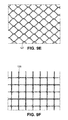
- FIG. 9E illustrates a mesh in an interlocking link configuration.
- FIG. 9F illustrates a knotted mesh
- FIG. 10 illustrates a mesh between two heated platens.
- FIG. 10A illustrates a mesh with strands of different materials between two heated platens.
- FIG. 11 illustrates a filled mesh
- FIG. 12 illustrates two different meshes laminated together.
- FIG. 12A illustrates two different meshes layered one on the other and having filled or sintered edges.
- FIG. 12B illustrates a mesh having a variable shape.
- FIG. 13 and FIG. 13A illustrate tubular forms of meshes.
- FIGS. 13B-1, 13B-2 and 13B-3 illustrate tubular forms of woven meshes which have been rolled upon themselves.
- FIG. 14 illustrates a flattened tubular mesh
- FIG. 14A illustrates a section of tubular mesh to be sealed at one or both ends.
- FIGS. 14B-1 and 14B-2 illustrate a multi-component flattened tubular mesh construct.
- FIGS. 14B-3 and 14B-4 illustrate a resected rib segment which is repaired using flattened tubular mesh.
- FIG. 14C illustrates a flattened tubular mesh with a movable member and a means of affixing the member relative to the mesh.
- FIGS. 14D-1 and 14D-2 illustrate an inner mesh member formed into a loop and adjusted through a tubular mesh member.
- FIG. 14D-3 illustrates a mesh strap with a fastener affixed to one end.
- FIGS. 14E-1 and 14E-2 illustrate flattened tubular mesh covering a bone plate.
- FIGS. 14E-3, 14E-4 and 14E-5 illustrate bone plates having mesh material laminated thereon
- FIGS. 15 and 15A illustrate rolled mesh tubes with and without a core.
- FIG. 16 illustrates a diagonally rolled mesh
- FIG. 16A illustrates a rolled pre-shaped mesh sheet.
- FIGS. 16B-1 , B- 2 , B- 3 and B- 4 illustrate a sequence using a rolled pre-shaped mesh sheet to make a hip stem.
- FIGS. 16C-1 , C- 2 , C- 3 and C- 4 illustrate the use of mesh and a core member to make a hip stem.
- FIG. 17 illustrates the structure of a compressed sintered mesh.
- FIG. 18 illustrates cancellous bone of the femur.
- FIG. 19 illustrates a bone plate with a mesh central section.
- FIG. 20 illustrates a woven mesh that has been fused and perforated.
- the invention has to do with implantable devices made from mesh materials.
- One or more than one type of mesh material can be used in an implantable device of the invention.
- the mesh material can be combined with non-mesh materials such as rods, tubes, solid sheets, perforated sheets, fillers and other materials of various shapes, forms and compositions to make a composite implant structure having sufficient strength to carry out its intended purpose.
- the implantable devices of the invention can be used to repair or replace a bone or a joint or reattach a tendon, muscle or cartilage. Novel mesh structures for soft tissue repair are also described.
- a woven implantable mesh consists of two sets of strands crossed over and under each other in a simple alternating pattern as shown in FIG. 1 .
- Strands 1 are approximately perpendicular to strands 2 and they intersect at points of contact 3 .
- the mesh can also be woven with a variable spacing between strands. This can occur along one axis or along both as shown in FIG. 3 wherein strands 5 and strands 6 are closely spaced along both axes as compared with strands 7 and strands 8 . This concept is subject to numerous variations as will be apparent to those having skill in the art.
- a loosely woven mesh can be created by alternating pairs of strands in each direction as shown in FIG. 4 where strand pair 10 alternates with strand pair 12 along one axis and strand pair 11 alternates with strand pair 13 along another axis. Variations of this include double strands along only one axis and one strand or numbers of strands greater than two in any direction.
- the material properties can be changed uniformly as shown in FIG. 6 or distinctly different directional properties can be created as shown in FIG. 7 .
- relatively stiff strands 17 are alternated with relatively flexible strands 18 along one axis and strands of one material 19 are alternated with strands of another material 20 along the other axis.
- relatively stiff strands 21 are along one axis and flexible strands 22 are along the other.
- FIGS. 1-7 show essentially round strands but they could also be flattened strips or intermediate shapes such as ovals.
- FIG. 8 shows a mesh with solid oval strands 23 in one direction and hollow round strands 24 in the other.
- FIGS. 9A-9F illustrate different types of knitted mesh.
- strands 121 and 122 are illustrated in a weft-knitted construction.
- FIG. 9B illustrates a warp-knitted construction with strands 123 and 124 .
- FIG. 9C shows a braided mesh using flat strands 125 and 126 .
- tubular braided mesh can be made, for example, following the construction of the braided shield for coaxial cable as illustrated in FIG. 9D .
- FIG. 9E illustrates a mesh having an interlocking link configuration using strands 127 .
- a knotted mesh with strands 128 is illustrated in FIG. 9F .
- the strand materials can come from any of the classes of biocompatible implant materials; metallics, bioresorbable polymers and non-resorbable polymers. In addition, organic materials such as collagen are suitable in some applications.
- the strands can have various physical structures. For example, they can be monofilament or thread or yarn structures. They can be braided or they can be hollow tubular structures and the hollow tubular structures can have a cross-section which is round, oval, square, rectangular, triangular or of any other closed geometric shape, including irregular shapes. If the hollow strands are porous or biodegradable, they can be filled with medication or bone growth substances to provide a timed release at the surgical site. A surgical mesh which incorporates a timed release of antibiotics is particularly attractive in abdominal wall or hernia repair.
- FIG. 10 illustrates a basic mesh 30 , as illustrated in FIG. 1 , between two heated platens 25 and 26 .
- the resulting mesh will be fused at each point of contact where the strands cross one another (i.e., at the intersections).
- adhesives, knots or other means known to those having skill in the art can be used to adhere the strands to one another at points of contact.
- FIG. 10A illustrates this concept. Variations on this concept would include a mesh material wherein most of the strands have a lower melting point than the others or wherein most of the strands have a higher melting point than the others.
- the lower melting point strands can be dispersed evenly, unevenly or in a specific woven pattern.
- One lower melting point strand or one higher melting point strand could be woven in a manner that would cause it to have one or more than one point of contact with itself, such as a woven loop.
- a sintered mesh material according to the invention could comprise higher melting point strands and at least one lower melting point strand having one or more than one point of contact with itself or two or more than two lower melting point strands having at least one of point of contact wherein the lower melting point strand or strands are sintered, and therefore affixed, at the point or points of contact.
- Another method of constraining the strands in a mesh is to fill the interstices between the strands with another biocompatible material thereby locking the strands in their relative positions. This also serves to combine the properties of the mesh material and the filler. In this manner, the mesh structure can act as a reinforcing element for the filler resulting in a composite material having properties superior to either material alone.
- Suitable filling materials include resorbable polymers, hydrogels, collagen as well as non-resorbable polymers. If this material is bioresorbable, then the gradual degradation of the bioresorbable component will alter the overall mechanical properties of the filled mesh over time. If the filling material is non-resorbable, then the mechanical properties will remain unchanged after implantation.
- a filling material that softens at a relatively low temperature also provides the advantage of allowing the mesh to be shaped intraoperatively. In surgery, it is often necessary to contour an implant to match the patient's anatomy and have the implant maintain the new contour while providing support to the tissue. Most polymer based meshes can be contoured but have the tendency to spring back to their original shape. Filling the mesh with a material that softens at a low temperature allows the implant to be heated in the operating room, contoured to fit the patient and then, after cooling, it maintains that form because the filler locks the strands in their new positions.
- FIG. 11 illustrates a filled woven mesh comprised of strands 27 , strands 28 and filling material 29 .
- This feature of intraoperatively reshaping an implant device is applicable to all of the embodiments of the invention wherein the materials used to make the implant (e.g., a mesh material, a combination of mesh materials or a combination of mesh material and non-mesh material) can be reshaped upon heating to a new contour that fits a patient's anatomy and the implant device maintains the new contour upon cooling.
- the materials used to make the implant e.g., a mesh material, a combination of mesh materials or a combination of mesh material and non-mesh material
- Implantable meshes can also be comprised of at least two sheets of mesh optionally adhered to one another, for example, laminated together or adhered to one another at predetermined discreet points of contact such as at points 32 a and 32 b in FIG. 12 .
- the layers in a laminated construction can be multiple layers of the same mesh or they can be comprised of layers of different mesh materials.
- the orientation of the strands can remain constant or be varied from layer to layer.
- FIG. 12 illustrates one possible configuration where only two layers are shown for clarity, the layers being comprised of the mesh 30 of FIG. 1 and the mesh 31 of FIG. 8 .
- a multilayer construction can have only the edges (i.e., the perimeter) sintered, filled or both.
- the center section remains flexible.
- FIG. 12A An example is shown in FIG. 12A wherein a filling material 32 is applied around the edges of layered meshes 33 and 34 to make a layered mesh composite 35 .
- Implantable mesh products can be produced in shapes other than flat sheets.
- FIG. 12B depicts a flat central section 36 which then tapers to a smaller, cable-like cross section 37 at each end (i.e., the opposing ends).
- the cable-like cross-section can also be described as a rope or strap and this portion of the device is made from the same material as the mesh material.
- Such a construct may be attached to a needle and sutured around bone or soft tissue to provide a larger area of support where required.
- Mesh may be fabricated in tubular form by weaving, knitting or braiding processes. (See FIGS. 9A-9D .) As with flat mesh materials, these tubular structures can incorporate multiple strand materials, process variations which produce a wide range of densities and strengths as well as three dimensional configurations. Rounds ( FIG. 13 illustrating woven round tubular mesh 38 ), ovals and flattened tubular forms ( FIG. 14 illustrating woven, flattened tubular mesh 44 ) are but a few examples and others will be apparent to those having skill in the art. These forms of mesh can also be sintered, filled or the like as previously described. One or more than one form may be inserted within the hollow core of another as illustrated in FIG. 13A which depicts a coaxial arrangement of cylindrical mesh tubes 38 and 39 .
- Tubular mesh structures can also be combined with rolled and compacted mesh structures in various configurations as will be apparent to those skilled in the art based on the disclosures herein.
- a cylindrical mesh tube can also be rolled down upon itself to form a ring-like structure 40 or 41 as shown in FIGS. 13B-1 and 13B-2 , respectively. It too can be rolled around an optional core element as shown in the section view 13 B- 3 illustrating core element 42 and mesh 43 .
- Flattened tubular mesh could be made by weaving, braiding or knitting to produce a flat, hollow cable or strap which additionally can be combined with many other components to form implantable medical devices.
- FIG. 14 shows a flattened tubular mesh 44 in its simplest form.
- a section of mesh 44 , sealed at one end can form a packet for containing medication and this can be used in the manner described in U.S. Pat. No. 6,916,483.
- the mesh structure permits body fluids to act upon the contents yet will contain them in a volume for implantation at a desired location in the body or in another implant.
- FIG. 14A illustrates this concept.
- the open end can be sealed intraoperatively using heat, adhesives, sutures or the like.
- Heating elements 45 and 46 are illustrated. These are moved in the directions of arrows 45 A and 46 A to seal one end 47 .
- both ends 47 and 48 can be sealed before implantation in a patient.
- FIGS. 14B-1 and 14B-2 illustrate a multi-component flattened tubular mesh construct.
- Outer layer 50 and intermediate layer 51 are flattened tubular mesh with a core strip 52 comprising a solid material or mesh. These components can be selected to provide strength, stiffness, a targeted resorption profile, tissue ingrowth properties, etc.
- one end of the outer member is partially cut away; the other forms a flattened tubular pocket.
- Such a construct can be slipped over the end of a segmentally resected rib, seating the rib in the pocket. This concept can also be applied to any fractured or incised bone.
- an open end of the flattened tubular mesh can be slipped over the end of the segmentally resected rib.
- an orthopedic implant which is comprised of a mesh material shaped in the form of a structure for repairing a bone. This is illustrated in FIGS. 14B-3 and 14B-4 where sleeves 55 and 56 are slipped over each end of the resected rib segment 57 . This can be reimplanted into the chest wall defect to achieve fusion.
- FIGS. 14C through 14D-3 the members can also be designed to be moveable relative to one another as shown in FIGS. 14C through 14D-3 .
- FIG. 14C illustrates an outer flattened tubular member 60 which can be fixed in position.
- the inner mesh strap 61 can be attached to tissue (hard or soft) and slid into or out of the outer member 60 which can be fixed by various means, for example, bracket 62 , thereby moving one tissue fixation point relative to the other.
- FIGS. 14D-1 and 14D-2 depict an inner mesh member 64 (cable or flat mesh) formed into a loop. Each end of this inner member is inserted through an opposite end of a flattened tubular mesh member 65 and then exits through lateral slots 66 and 67 .
- FIG. 14D-3 illustrates a single mesh strap 68 with a fastener 69 on one end. The free end of the mesh strap 68 is inserted through the slot in the fastener forming a loop, and by pulling on this end, the loop can be tightened.
- FIGS. 14E-1 and 14E-2 illustrate this embodiment. These figures show the mesh 70 being perforated after being drawn over the bone plate structure 71 to expose the fastener holes 72 . This perforation process can be performed with a heated punch to fuse, at least partially, the mesh to the plate and/or to fuse the edges of the holes to the mesh 70 .
- the bone plate structure 71 can be comprised of a solid material or it can be comprised of mesh material which is the same as or different from mesh 70 .
- the bone plate structure 71 can be a filled and/or laminated mesh, a sintered mesh, a mesh strap or other mesh of the types described herein. It could also be a solid metal or plastic or a combination thereof or a combination of solid material and mesh material (e.g., a laminate) and it could be comprised of a resorbable, non-resorbable or a combination of resorbable and non-resorbable materials.
- FIGS. 14E-3 , E- 4 and E- 5 Each figure illustrates a section view of bone plate structure 71 .
- mesh material 73 is laminated to the top surface of bone plate structure 71 .
- mesh material 74 is laminated to the bottom surface of bone plate structure 71 .
- mesh material 73 is laminated to the top surface and mesh material 74 is laminated to the bottom surface of bone plate structure 71 .
- Tubular mesh structures may also be created by rolling up sheets of mesh. These can be single sheets, laminated sheets, sintered sheets or filled sheets or any combination thereof.
- a shaped core can be used in the process and this core may become part of the implant or may only be used for a portion of the fabrication process.
- This core can be solid, tubular or shaped, and it can be comprised of any implant materials known in the art.
- the core can be a composite of various implant materials and it may also take the form of a partial core if required. It is also possible to roll the mesh sheets with no core. Afterwards the rolled construct can be formed into a final cross-sectional shape using heat and/or pressure, adhesives, filling material, any flowable material that can be hardened by curing, etc.
- FIG. 15 illustrates a tube 75 rolled parallel to one of the strand directions and parallel to the edge of the mesh sheet. In the finished form, the mechanical properties will be uniform over the length of the tube.
- FIG. 15A shows a mesh sheet 76 rolled around a core 77 .
- FIG. 16 illustrates a mesh 80 rolled diagonally with respect to the edges of the sheet 81 and 82 .
- a tube When rolling is complete, a tube will be formed and the middle of the tube will have the greatest number of mesh layers. This number will steadily decrease as one moves from the middle toward either end of the tube. In this way, a variable stiffness mesh tube may be created.
- the ends of the tube can be cut square if desired. Furthermore the tube can be sectioned at any point to create the desired properties at an end.
- this concept can be carried further by shaping the mesh sheet prior to rolling.
- FIG. 16A The sheet of mesh 86 in this case is essentially the full sheet from FIG. 16 , cut diagonally with one corner truncated. When this shaped sheet is rolled, the result will be a tubular member with a stiffness that decreases from edge 87 to edge 88 .
- FIGS. 16B through 16E illustrate the use of a rolled, pre-shaped sheet as part of a larger process to produce a more complex shape.
- the process starts with a pre-cut or pre-shaped sheet of mesh 90 that is rolled lengthwise ( FIG. 16B-1 ) in the direction of arrow 91 .
- the result is a wrapped preform 92 with an axis of symmetry 93 ( FIG. 16B-2 ).
- This preform is then placed between two platens 94 and 95 ( FIG. 16B-3 ).
- Each platen has a cavity conforming to half of the final shape of the implant.
- Heat and/or pressure is used to compress and/or sinter the preform to the desired final shape—in this case a hip stem 96 ( FIG. 16B-4 ).
- an orthopedic implant which is comprised of a mesh material shaped in the form of a structure (a prosthesis) for replacing a bone and/or a joint.
- FIGS. 16C-1 through 16C-4 depict a different use of mesh to form a complex implant shape—in this case another hip stem.
- a core comprised of a main shaft 100 and arm 101 is wrapped by a mesh strip 102 ( FIG. 16C-1 ).
- This process proceeds much as one would tape an ankle or wrist, until the desired intermediate shape 103 is achieved ( FIG. 16C-2 ).
- the intermediate shape 103 is pressed between two shaped platens 104 and 105 ( FIG. 16C-3 ) to achieve the final implant 106 ( FIG. 16C-4 ).
- More complex three-dimensional shapes can be formed by compacting the implantable mesh, similar to wadding up a piece of paper to throw in the trash. This can be done with single sheets, laminated sheets, rolled sheets, sintered sheets or filled sheets of mesh, or any combination thereof. Once the mesh is compacted into the desired shape, it can be locked in place by sintering and/or filling the strands. While a hip stem is illustrated, obviously this process could be used to produce a wide range of implants including bone plates, screws, rods, etc. The resulting three-dimensional structure of a compressed, sintered mesh ( FIG. 17 ) is quite similar to that of cancellous bone ( FIG. 18 ). Additionally, it is possible to coat this three dimensional mesh structure with other implant materials to provide an outer layer which is not mesh based.
- FIG. 19 illustrates a bone plate 110 with a mesh central section 111 , solid ends 112 for attachment to the bone and optional sides 113 .
- Bone plate 110 can be manufactured by, for example, cutting a piece of mesh to approximately the shape and size of bone plate 110 , filling the ends and side with a curable, flowable filling material and then curing the filling material.
- An alternative embodiment could be made without sides 113 .
- the ends and/or sides of bone plate 110 can be made of a material which softens on heating so that it can be conformed to the shape of the operating site of the patient. Then it would harden and retain its shape at body temperature.
- the central section was filled with a bioresorbable material (not shown), it would initially be stiff but then would gradually transfer the mechanical load to the bone as the bioresorbable material degrades. The result would be an implant of reduced residual mass that would prevent stress shielding.
- bioresorbable filling material would also allow the implant to be heated to the softening point of the bioresorbable material for intraoperative contouring of the implant to the bone surface.
- the mesh material also can be perforated.
- the perforation process can be combined with heat to fuse the perforated edges to prevent fraying or loosening of the fibers or strands.
- FIG. 20 illustrates this concept.
- Mesh structures provide a means of producing surgical and orthopedic implants with enhanced properties. They represent a method of combining a wide range of existing implant materials in new ways to maximize their advantages and minimize their individual limitations.
- Strands of various materials can be interwoven at the mesh level.
- Various fabrication methods e.g., weaving, knitting, braiding and perforating
- Layers of different mesh can be laminated together to produce a hybrid implant material with properties precisely tailored to the clinical indication.
- These mesh structures can be further reinforced by sintering the strands to prevent movement and/or by encapsulating them in another material. In this manner, an implant can be made with properties not found in the current selection of biomaterials.
- Implants for fracture fixation could be made with the required initial strength but also with the ability to partially or completely resorb preventing stress shielding, minimizing the amount of residual foreign material in the patient and reducing the number of second (removal) surgeries.
- Reconstructive implants could be made with internal structures similar to cancellous bone, thus offering a better combination of strength, resiliency and reduced weight.
- Surgical meshes for muscle, ligament or tendon repair and/or reattachment to bone can be wholly or partially resorbable and offer the ability to deliver antibiotics or other medications to the local surgical site.
- the exposed surfaces of implants could be designed either to encourage or discourage the ingrowth of hard or soft tissues. The net result is a new class of biomaterials with enhanced mechanical and biological properties.
Abstract
Description
Claims (13)
Priority Applications (1)
| Application Number | Priority Date | Filing Date | Title |
|---|---|---|---|
| US13/040,072 US9814577B2 (en) | 2007-07-18 | 2011-03-03 | Implantable mesh for musculoskeletal trauma, orthopedic reconstruction and soft tissue repair |
Applications Claiming Priority (2)
| Application Number | Priority Date | Filing Date | Title |
|---|---|---|---|
| US11/779,559 US20090024147A1 (en) | 2007-07-18 | 2007-07-18 | Implantable mesh for musculoskeletal trauma, orthopedic reconstruction and soft tissue repair |
| US13/040,072 US9814577B2 (en) | 2007-07-18 | 2011-03-03 | Implantable mesh for musculoskeletal trauma, orthopedic reconstruction and soft tissue repair |
Related Parent Applications (1)
| Application Number | Title | Priority Date | Filing Date |
|---|---|---|---|
| US11/779,559 Continuation US20090024147A1 (en) | 2007-07-18 | 2007-07-18 | Implantable mesh for musculoskeletal trauma, orthopedic reconstruction and soft tissue repair |
Publications (2)
| Publication Number | Publication Date |
|---|---|
| US20110152865A1 US20110152865A1 (en) | 2011-06-23 |
| US9814577B2 true US9814577B2 (en) | 2017-11-14 |
Family
ID=40259978
Family Applications (2)
| Application Number | Title | Priority Date | Filing Date |
|---|---|---|---|
| US11/779,559 Abandoned US20090024147A1 (en) | 2007-07-18 | 2007-07-18 | Implantable mesh for musculoskeletal trauma, orthopedic reconstruction and soft tissue repair |
| US13/040,072 Active US9814577B2 (en) | 2007-07-18 | 2011-03-03 | Implantable mesh for musculoskeletal trauma, orthopedic reconstruction and soft tissue repair |
Family Applications Before (1)
| Application Number | Title | Priority Date | Filing Date |
|---|---|---|---|
| US11/779,559 Abandoned US20090024147A1 (en) | 2007-07-18 | 2007-07-18 | Implantable mesh for musculoskeletal trauma, orthopedic reconstruction and soft tissue repair |
Country Status (10)
| Country | Link |
|---|---|
| US (2) | US20090024147A1 (en) |
| EP (1) | EP2166989B1 (en) |
| JP (1) | JP2010533551A (en) |
| KR (1) | KR20100035706A (en) |
| CN (1) | CN101754730A (en) |
| AU (1) | AU2008276381A1 (en) |
| CA (1) | CA2695119C (en) |
| MX (1) | MX2010000060A (en) |
| RU (1) | RU2010105687A (en) |
| WO (1) | WO2009012001A1 (en) |
Cited By (1)
| Publication number | Priority date | Publication date | Assignee | Title |
|---|---|---|---|---|
| US11766332B2 (en) | 2016-07-26 | 2023-09-26 | Warsaw Orthopedic, Inc. | Implantable mesh |
Families Citing this family (71)
| Publication number | Priority date | Publication date | Assignee | Title |
|---|---|---|---|---|
| US20090192530A1 (en) * | 2008-01-29 | 2009-07-30 | Insightra Medical, Inc. | Fortified mesh for tissue repair |
| US20090187197A1 (en) * | 2007-08-03 | 2009-07-23 | Roeber Peter J | Knit PTFE Articles and Mesh |
| US9034002B2 (en) | 2008-02-18 | 2015-05-19 | Covidien Lp | Lock bar spring and clip for implant deployment device |
| US9301826B2 (en) | 2008-02-18 | 2016-04-05 | Covidien Lp | Lock bar spring and clip for implant deployment device |
| US9044235B2 (en) | 2008-02-18 | 2015-06-02 | Covidien Lp | Magnetic clip for implant deployment device |
| US8808314B2 (en) | 2008-02-18 | 2014-08-19 | Covidien Lp | Device and method for deploying and attaching an implant to a biological tissue |
| US9393002B2 (en) | 2008-02-18 | 2016-07-19 | Covidien Lp | Clip for implant deployment device |
| US9393093B2 (en) | 2008-02-18 | 2016-07-19 | Covidien Lp | Clip for implant deployment device |
| EP2247245B1 (en) | 2008-02-18 | 2017-06-28 | Covidien LP | A device for deploying and attaching a patch to a biological tissue |
| US9398944B2 (en) | 2008-02-18 | 2016-07-26 | Covidien Lp | Lock bar spring and clip for implant deployment device |
| US8317808B2 (en) | 2008-02-18 | 2012-11-27 | Covidien Lp | Device and method for rolling and inserting a prosthetic patch into a body cavity |
| US8758373B2 (en) | 2008-02-18 | 2014-06-24 | Covidien Lp | Means and method for reversibly connecting a patch to a patch deployment device |
| US9833240B2 (en) | 2008-02-18 | 2017-12-05 | Covidien Lp | Lock bar spring and clip for implant deployment device |
| EP2349037A2 (en) * | 2008-08-06 | 2011-08-03 | Allosource | Kerf cranial closure methods and device |
| EP2792307B1 (en) | 2008-10-20 | 2017-10-04 | Covidien LP | A device for attaching a patch to a biological tissue |
| DE102009008688A1 (en) * | 2009-02-06 | 2010-08-19 | Aesculap Ag | Closing implant i.e. craniotomy closure, for closing large cranial bone openings in skull of patient, has closure elements separated from each other and directly or indirectly movable relative to each other |
| WO2010093950A1 (en) * | 2009-02-12 | 2010-08-19 | Osteotech, Inc. | Delivery system cartridge |
| US8591582B2 (en) | 2009-02-26 | 2013-11-26 | Depuy International Limited | Support structure implant for a bone cavity |
| GB0903250D0 (en) | 2009-02-26 | 2009-04-08 | Depuy Int Ltd | Support structure implant for a bone cavity |
| US10159512B2 (en) | 2009-03-17 | 2018-12-25 | Bonfix Ltd | Hallux abducto valgus assemblies |
| AU2010286117B9 (en) | 2009-08-17 | 2014-07-10 | Covidien Lp | Articulating patch deployment device and method of use |
| AU2010286116B2 (en) | 2009-08-17 | 2014-06-26 | Covidien Lp | Means and method for reversibly connecting an implant to a deployment device |
| DE102009060799A1 (en) * | 2009-12-31 | 2011-07-07 | Aesculap AG, 78532 | Textile network, in particular for the treatment or treatment of prolapse or for the prevention of dyspareunia |
| US9510925B2 (en) * | 2010-02-02 | 2016-12-06 | Covidien Lp | Surgical meshes |
| US20120095482A1 (en) * | 2010-05-11 | 2012-04-19 | Dale Peterson | Endoprosthetic textile scaffold |
| US20120046517A1 (en) * | 2010-08-18 | 2012-02-23 | Konstantin Lazarov Valtchev | Second generation tape |
| AU2011298049B2 (en) | 2010-08-29 | 2016-02-18 | Bonfix Ltd. | Orthopedic implant for treatment of bone deformities |
| WO2012107722A1 (en) * | 2011-02-08 | 2012-08-16 | Rami Atalla | Very lightweight surgical mesh for vaginal prolapse repair |
| CN102293692A (en) * | 2011-06-18 | 2011-12-28 | 四川大学 | Bionic bone-repairing stent body with laminated structure and preparation method thereof |
| WO2012177759A1 (en) | 2011-06-20 | 2012-12-27 | Rdc Holdings, Llc | System and method for repairing joints |
| US8998925B2 (en) | 2011-06-20 | 2015-04-07 | Rdc Holdings, Llc | Fixation system for orthopedic devices |
| US8900617B2 (en) * | 2011-07-21 | 2014-12-02 | Warsaw Orthopedic, Inc. | Bio-Remodable Bone Augmentation device and method |
| ES2763336T3 (en) * | 2012-02-28 | 2020-05-28 | Incorpracyl Tech Ltd | Tissue support structure |
| US9149354B2 (en) | 2012-07-20 | 2015-10-06 | Anthony E. Sudekum | Flexor tendon repair device |
| EP2943131B1 (en) * | 2013-01-09 | 2019-07-17 | Cook Medical Technologies LLC | Abdominal retractor |
| AU2014212444B2 (en) * | 2013-01-29 | 2017-05-18 | Chester Evan Sutterlin | Occipital plate assemblies with polyaxial head connectors |
| US9585695B2 (en) | 2013-03-15 | 2017-03-07 | Woven Orthopedic Technologies, Llc | Surgical screw hole liner devices and related methods |
| CN103519921B (en) * | 2013-09-30 | 2016-08-17 | 暨南大学 | A kind of humerus or the reconstructing device of near end of thighbone |
| RU2553207C2 (en) * | 2013-11-01 | 2015-06-10 | Сергей Владимирович Шалашов | Device for plasty in case of post-operative hernia of anterior abdominal wall |
| US9907593B2 (en) | 2014-08-05 | 2018-03-06 | Woven Orthopedic Technologies, Llc | Woven retention devices, systems and methods |
| US8956394B1 (en) | 2014-08-05 | 2015-02-17 | Woven Orthopedic Technologies, Llc | Woven retention devices, systems and methods |
| US20160074071A1 (en) | 2014-09-16 | 2016-03-17 | Woven Orthopedic Technologies, Llc | Methods of using woven retention devices and systems |
| AU2015332133A1 (en) * | 2014-10-14 | 2017-04-20 | Antonio Sambusseti | Absorbable device for bone regeneration |
| USD740427S1 (en) | 2014-10-17 | 2015-10-06 | Woven Orthopedic Technologies, Llc | Orthopedic woven retention device |
| RU2620494C2 (en) * | 2014-10-23 | 2017-05-25 | Артур Магомедович Омаров | Implant unit for reconstruction of defective bone and method for reconstruction of defective bone |
| US10555758B2 (en) | 2015-08-05 | 2020-02-11 | Woven Orthopedic Technologies, Llc | Tapping devices, systems and methods for use in bone tissue |
| KR20170026847A (en) | 2015-08-31 | 2017-03-09 | 성균관대학교산학협력단 | Baby carriage with automatic breaking function |
| US10130738B2 (en) * | 2015-08-31 | 2018-11-20 | Ethicon Llc | Adjunct material to promote tissue growth |
| US10596660B2 (en) * | 2015-12-15 | 2020-03-24 | Howmedica Osteonics Corp. | Porous structures produced by additive layer manufacturing |
| CN105496609B (en) * | 2015-12-17 | 2017-12-01 | 北京市春立正达医疗器械股份有限公司 | One kind overhauls titanium net |
| WO2018044188A1 (en) * | 2016-08-29 | 2018-03-08 | Олег Викторович БАРЗИНСКИЙ | Implant for repairing bone defects |
| KR20220149620A (en) * | 2016-11-03 | 2022-11-08 | 아리조나 보드 오브 리전츠 온 비해프 오브 더 유니버시티 오브 아리조나 | Stacked tissue encapsulation device systems with or without oxygen delivery |
| WO2018107114A1 (en) | 2016-12-09 | 2018-06-14 | Woven Orthopedic Technologies, LLC. | Retention devices, lattices and related systems and methods |
| KR101922966B1 (en) * | 2017-02-22 | 2018-11-28 | 가톨릭관동대학교산학협력단 | Manufacturing method of implant for orbital wall and implant for orbital wall |
| CN110494101B (en) * | 2017-03-29 | 2022-05-27 | 佛兰芒技术研究所有限公司 | Surgical implant comprising a hierarchical porous structure |
| RU2644550C1 (en) * | 2017-05-10 | 2018-02-12 | Федеральное государственное бюджетное учреждение "Московский научно-исследовательский институт глазных болезней имени Гельмгольца" Министерства здравоохранения Российской Федерации | Method of glaucoma surgical treatment |
| US11628517B2 (en) | 2017-06-15 | 2023-04-18 | Howmedica Osteonics Corp. | Porous structures produced by additive layer manufacturing |
| DE102017115404A1 (en) * | 2017-07-10 | 2019-01-10 | Karl Leibinger Medizintechnik Gmbh & Co. Kg | Bone augmentation piece and bone augmentation piece kit with inserted (dental) implant |
| CA3079532A1 (en) | 2017-10-19 | 2019-04-25 | C.R.Bard, Inc. | Self-gripping hernia prosthesis |
| US10499966B2 (en) * | 2017-10-24 | 2019-12-10 | DePuy Synthes Products, Inc. | Bone fixation system including an implant having a plate portion and a mesh portion |
| EP3479798B1 (en) | 2017-11-03 | 2023-06-21 | Howmedica Osteonics Corp. | Flexible construct for femoral reconstruction |
| RU2675049C1 (en) * | 2017-11-13 | 2018-12-14 | Федеральное государственное бюджетное учреждение "Российский ордена Трудового Красного Знамени научно-исследовательский институт травматологии и ортопедии имени Р.Р. Вредена" Министерства здравоохранения Российской Федерации (ФГБУ "РНИИТО им. Р.Р. Вредена" Минздрава России) | Device for replacing defects of proximal femur when performing revision hip replacement |
| USD875252S1 (en) * | 2018-02-09 | 2020-02-11 | Riverpoint Medical, Llc | Implantable surgical membrane |
| USD875251S1 (en) * | 2018-02-09 | 2020-02-11 | Riverpoint Medical, Llc | Implantable surgical membrane |
| EP3653171A1 (en) * | 2018-11-16 | 2020-05-20 | Sofradim Production | Implants suitable for soft tissue repair |
| DE102018130205A1 (en) * | 2018-11-28 | 2020-05-28 | Aesculap Ag | Medical chain network |
| CN109893305B (en) * | 2019-04-16 | 2021-03-23 | 南京医科大学附属逸夫医院 | Tissue engineering scaffold with partitions |
| JP2022539893A (en) * | 2019-07-10 | 2022-09-13 | アスクレーピオス コーポレイション | Systems, devices and methods for bone suture attachment and support |
| GB2589600B (en) * | 2019-12-04 | 2022-03-02 | Veterinary Tissue Bank Ltd | A DBM scaffold product and a method of manufacturing the same |
| US20230041443A1 (en) * | 2020-02-05 | 2023-02-09 | Fuji Filter Manufacturing Co., Ltd. | Implant for bone fracture treatment and method for manufacturing implant for bone fracture treatment |
| CN112370098B (en) * | 2020-10-20 | 2022-02-25 | 广东施泰宝医疗科技有限公司 | Tendon suture system for joint replacement |
Citations (36)
| Publication number | Priority date | Publication date | Assignee | Title |
|---|---|---|---|---|
| US1156440A (en) | 1915-01-29 | 1915-10-12 | John X Smith | Fracture-clamp. |
| US3040741A (en) | 1958-12-15 | 1962-06-26 | Puritan Compressed Gas Corp | Quick donning harness for oxygen masks |
| US3463158A (en) | 1963-10-31 | 1969-08-26 | American Cyanamid Co | Polyglycolic acid prosthetic devices |
| US3710789A (en) | 1970-12-04 | 1973-01-16 | Univ Minnesota | Method of repairing bone fractures with expanded metal |
| US4883486A (en) | 1988-05-31 | 1989-11-28 | Indu Kapadia | Prosthetic ligament |
| US5139497A (en) | 1991-11-25 | 1992-08-18 | Timesh, Inc. | Orbital repair implant |
| US5139528A (en) | 1988-02-26 | 1992-08-18 | Sulzer Brothers Limited | Method of securing a mesh to a metal substrate for a bone implant |
| US5195542A (en) | 1989-04-27 | 1993-03-23 | Dominique Gazielly | Reinforcement and supporting device for the rotator cuff of a shoulder joint of a person |
| US5368602A (en) * | 1993-02-11 | 1994-11-29 | De La Torre; Roger A. | Surgical mesh with semi-rigid border members |
| US5397359A (en) * | 1991-08-07 | 1995-03-14 | Oscobal Ag | Metal wire structure for endoprosthetics |
| US5443483A (en) | 1993-04-22 | 1995-08-22 | Axel Kirsch | Appliance for accelerating the healing of a bone surgery site |
| US5468242A (en) | 1993-11-19 | 1995-11-21 | Leibinger Gmbh | Form-fitting mesh implant |
| US5549619A (en) | 1991-06-04 | 1996-08-27 | Clinical Product Development Limited | Medical/surgical devices |
| US5779706A (en) * | 1992-06-15 | 1998-07-14 | Medicon Eg | Surgical system |
| US5824088A (en) * | 1994-04-27 | 1998-10-20 | Kirsch; Axel | Cover device for bone voids and method for the manufacture thereof |
| JPH1156862A (en) | 1997-08-12 | 1999-03-02 | Ikufumi Yamada | Smoother for ligament reconstruction |
| US5948020A (en) | 1995-05-01 | 1999-09-07 | Sam Yang Co., Ltd. | Implantable bioresorbable membrane and method for the preparation thereof |
| US5980540A (en) | 1997-04-11 | 1999-11-09 | Kinamed, Inc. | Perforated cover for covering spaces in the cranium and conforming to the shape of the cranium |
| US6071291A (en) | 1997-10-21 | 2000-06-06 | Howmedica Leibinger Gmbh & Co. Kg (Leibinger) | Micro dynamic mesh |
| US6113640A (en) | 1997-06-11 | 2000-09-05 | Bionx Implants Oy | Reconstructive bioabsorbable joint prosthesis |
| US6232354B1 (en) | 1999-01-25 | 2001-05-15 | Seng C. Tan | Microcellular polymer foams and method for their production |
| US6280473B1 (en) | 1996-08-19 | 2001-08-28 | Macropore, Inc. | Resorbable, macro-porous, non-collapsing and flexible membrane barrier for skeletal repair and regeneration |
| US6391059B1 (en) | 1998-04-07 | 2002-05-21 | Macropore, Inc. | Membrane with tissue-guiding surface corrugations |
| US6391060B1 (en) * | 1997-10-22 | 2002-05-21 | Sofradim Productions | Prosthetic implant for obstructing an anatomical duct, and obstructing assembly comprising same |
| US20020123750A1 (en) | 2001-02-28 | 2002-09-05 | Lukas Eisermann | Woven orthopedic implants |
| US20020173854A1 (en) | 2001-01-25 | 2002-11-21 | Tecomet, Inc. | Method for making a mesh-and-plate surgical implant |
| US6497728B2 (en) * | 2000-02-16 | 2002-12-24 | Korea Advanced Institute Of Science And Technology | Metal jacket for a cementless artificial joint stem and artificial joint having the jacket |
| US6585769B1 (en) * | 1999-04-05 | 2003-07-01 | Howmedica Osteonics Corp. | Artificial spinal ligament |
| US20050015154A1 (en) | 2003-06-25 | 2005-01-20 | Baylor College Of Medicine Office Of Technology Administration | Tissue integration design for seamless implant fixation |
| US20050054998A1 (en) * | 2003-09-05 | 2005-03-10 | Poccia John F. | Absorbent article |
| US20050260247A1 (en) | 2002-07-22 | 2005-11-24 | Ralph James D | Implantable prosthetic devices containing timed release therapeutic agents |
| US20050283255A1 (en) | 2001-06-04 | 2005-12-22 | Perry Geremakis | Tissue-derived mesh for orthopedic regeneration |
| US20060264948A1 (en) * | 2005-05-03 | 2006-11-23 | Williams Lytton A | Bone anchored surgical mesh |
| US20070270812A1 (en) * | 2006-04-14 | 2007-11-22 | Sdgi Holdings, Inc. | Fixation plate and method of use |
| US20080004714A1 (en) * | 2006-06-28 | 2008-01-03 | The Cleveland Clinic Foundation | Anti-adhesion membrane |
| US20080262630A1 (en) * | 2005-10-13 | 2008-10-23 | Synthes (U.S.A. | Drug-Impregnated Encasement |
-
2007
- 2007-07-18 US US11/779,559 patent/US20090024147A1/en not_active Abandoned
-
2008
- 2008-06-13 RU RU2010105687/14A patent/RU2010105687A/en unknown
- 2008-06-13 JP JP2010517043A patent/JP2010533551A/en not_active Withdrawn
- 2008-06-13 CN CN200880024988A patent/CN101754730A/en active Pending
- 2008-06-13 MX MX2010000060A patent/MX2010000060A/en not_active Application Discontinuation
- 2008-06-13 KR KR1020107000764A patent/KR20100035706A/en not_active Application Discontinuation
- 2008-06-13 AU AU2008276381A patent/AU2008276381A1/en not_active Abandoned
- 2008-06-13 WO PCT/US2008/066806 patent/WO2009012001A1/en active Application Filing
- 2008-06-13 EP EP08770918.4A patent/EP2166989B1/en not_active Not-in-force
- 2008-06-13 CA CA2695119A patent/CA2695119C/en not_active Expired - Fee Related
-
2011
- 2011-03-03 US US13/040,072 patent/US9814577B2/en active Active
Patent Citations (37)
| Publication number | Priority date | Publication date | Assignee | Title |
|---|---|---|---|---|
| US1156440A (en) | 1915-01-29 | 1915-10-12 | John X Smith | Fracture-clamp. |
| US3040741A (en) | 1958-12-15 | 1962-06-26 | Puritan Compressed Gas Corp | Quick donning harness for oxygen masks |
| US3463158A (en) | 1963-10-31 | 1969-08-26 | American Cyanamid Co | Polyglycolic acid prosthetic devices |
| US3710789A (en) | 1970-12-04 | 1973-01-16 | Univ Minnesota | Method of repairing bone fractures with expanded metal |
| US5139528A (en) | 1988-02-26 | 1992-08-18 | Sulzer Brothers Limited | Method of securing a mesh to a metal substrate for a bone implant |
| US4883486A (en) | 1988-05-31 | 1989-11-28 | Indu Kapadia | Prosthetic ligament |
| US5195542A (en) | 1989-04-27 | 1993-03-23 | Dominique Gazielly | Reinforcement and supporting device for the rotator cuff of a shoulder joint of a person |
| US5549619A (en) | 1991-06-04 | 1996-08-27 | Clinical Product Development Limited | Medical/surgical devices |
| US5397359A (en) * | 1991-08-07 | 1995-03-14 | Oscobal Ag | Metal wire structure for endoprosthetics |
| US5139497A (en) | 1991-11-25 | 1992-08-18 | Timesh, Inc. | Orbital repair implant |
| US5779706A (en) * | 1992-06-15 | 1998-07-14 | Medicon Eg | Surgical system |
| US5368602A (en) * | 1993-02-11 | 1994-11-29 | De La Torre; Roger A. | Surgical mesh with semi-rigid border members |
| US5443483A (en) | 1993-04-22 | 1995-08-22 | Axel Kirsch | Appliance for accelerating the healing of a bone surgery site |
| US5468242A (en) | 1993-11-19 | 1995-11-21 | Leibinger Gmbh | Form-fitting mesh implant |
| US5824088A (en) * | 1994-04-27 | 1998-10-20 | Kirsch; Axel | Cover device for bone voids and method for the manufacture thereof |
| US5948020A (en) | 1995-05-01 | 1999-09-07 | Sam Yang Co., Ltd. | Implantable bioresorbable membrane and method for the preparation thereof |
| US6280473B1 (en) | 1996-08-19 | 2001-08-28 | Macropore, Inc. | Resorbable, macro-porous, non-collapsing and flexible membrane barrier for skeletal repair and regeneration |
| US5980540A (en) | 1997-04-11 | 1999-11-09 | Kinamed, Inc. | Perforated cover for covering spaces in the cranium and conforming to the shape of the cranium |
| US6113640A (en) | 1997-06-11 | 2000-09-05 | Bionx Implants Oy | Reconstructive bioabsorbable joint prosthesis |
| JPH1156862A (en) | 1997-08-12 | 1999-03-02 | Ikufumi Yamada | Smoother for ligament reconstruction |
| US6071291A (en) | 1997-10-21 | 2000-06-06 | Howmedica Leibinger Gmbh & Co. Kg (Leibinger) | Micro dynamic mesh |
| US6391060B1 (en) * | 1997-10-22 | 2002-05-21 | Sofradim Productions | Prosthetic implant for obstructing an anatomical duct, and obstructing assembly comprising same |
| US6391059B1 (en) | 1998-04-07 | 2002-05-21 | Macropore, Inc. | Membrane with tissue-guiding surface corrugations |
| US6232354B1 (en) | 1999-01-25 | 2001-05-15 | Seng C. Tan | Microcellular polymer foams and method for their production |
| US6585769B1 (en) * | 1999-04-05 | 2003-07-01 | Howmedica Osteonics Corp. | Artificial spinal ligament |
| US6497728B2 (en) * | 2000-02-16 | 2002-12-24 | Korea Advanced Institute Of Science And Technology | Metal jacket for a cementless artificial joint stem and artificial joint having the jacket |
| US20020173854A1 (en) | 2001-01-25 | 2002-11-21 | Tecomet, Inc. | Method for making a mesh-and-plate surgical implant |
| US20050043733A1 (en) * | 2001-02-28 | 2005-02-24 | Lukas Eisermann | Woven orthopedic implants |
| US20020123750A1 (en) | 2001-02-28 | 2002-09-05 | Lukas Eisermann | Woven orthopedic implants |
| US20050283255A1 (en) | 2001-06-04 | 2005-12-22 | Perry Geremakis | Tissue-derived mesh for orthopedic regeneration |
| US20050260247A1 (en) | 2002-07-22 | 2005-11-24 | Ralph James D | Implantable prosthetic devices containing timed release therapeutic agents |
| US20050015154A1 (en) | 2003-06-25 | 2005-01-20 | Baylor College Of Medicine Office Of Technology Administration | Tissue integration design for seamless implant fixation |
| US20050054998A1 (en) * | 2003-09-05 | 2005-03-10 | Poccia John F. | Absorbent article |
| US20060264948A1 (en) * | 2005-05-03 | 2006-11-23 | Williams Lytton A | Bone anchored surgical mesh |
| US20080262630A1 (en) * | 2005-10-13 | 2008-10-23 | Synthes (U.S.A. | Drug-Impregnated Encasement |
| US20070270812A1 (en) * | 2006-04-14 | 2007-11-22 | Sdgi Holdings, Inc. | Fixation plate and method of use |
| US20080004714A1 (en) * | 2006-06-28 | 2008-01-03 | The Cleveland Clinic Foundation | Anti-adhesion membrane |
Non-Patent Citations (2)
| Title |
|---|
| Keskin et al, Collagen-chondroitin sulfate-based PLLA-SAIB-coated rhBMP-2 delivery system for bone repair; Biomaterials 26 (2005) 4023-4034, available online Nov. 13, 2004 (Introduction; Fig. 4). |
| Supplementary European Search Report dated Jun. 25, 2013. |
Cited By (1)
| Publication number | Priority date | Publication date | Assignee | Title |
|---|---|---|---|---|
| US11766332B2 (en) | 2016-07-26 | 2023-09-26 | Warsaw Orthopedic, Inc. | Implantable mesh |
Also Published As
| Publication number | Publication date |
|---|---|
| EP2166989A4 (en) | 2013-08-07 |
| AU2008276381A1 (en) | 2009-01-22 |
| EP2166989B1 (en) | 2017-03-08 |
| US20090024147A1 (en) | 2009-01-22 |
| RU2010105687A (en) | 2011-08-27 |
| MX2010000060A (en) | 2010-03-22 |
| EP2166989A1 (en) | 2010-03-31 |
| WO2009012001A1 (en) | 2009-01-22 |
| CN101754730A (en) | 2010-06-23 |
| US20110152865A1 (en) | 2011-06-23 |
| CA2695119C (en) | 2016-03-29 |
| CA2695119A1 (en) | 2009-01-22 |
| JP2010533551A (en) | 2010-10-28 |
| KR20100035706A (en) | 2010-04-06 |
Similar Documents
| Publication | Publication Date | Title |
|---|---|---|
| US9814577B2 (en) | Implantable mesh for musculoskeletal trauma, orthopedic reconstruction and soft tissue repair | |
| US6113640A (en) | Reconstructive bioabsorbable joint prosthesis | |
| AU708260B2 (en) | Joint prosthesis | |
| JP5893672B2 (en) | Drug impregnation container | |
| US10709539B2 (en) | Three-dimensional polymeric medical implants | |
| US6827743B2 (en) | Woven orthopedic implants | |
| US20170165077A1 (en) | Retention devices, lattices and related systems and methods | |
| CN100490752C (en) | Artificial intervertebral disk insertion jig, jig set, and artificial intervertebral disk | |
| EP2762172B1 (en) | Three-Dimensional Polymeric Medical Implants | |
| CN104024507A (en) | Knit With Zones Without Barbs, Method Of Making Same And Prostheses Obtained Therefrom | |
| US20230200856A1 (en) | Retention devices, lattices and related systems and methods | |
| CN112494174A (en) | Interface rivet weaving nail sheath device and manufacturing method thereof | |
| DE102016222603A1 (en) | Implant and a kit for treating a bone defect | |
| US20230001051A1 (en) | A dbm scaffold product and a method of manufacturing the same | |
| US20180168791A1 (en) | Implantable areal device for supporting tissue | |
| CN214259573U (en) | Interface rivet weaving nail sheath device | |
| Gupta | Shaped biotextiles for medical implants | |
| CN114642771A (en) | Artificial ligament with traction unit and preparation method thereof |
Legal Events
| Date | Code | Title | Description |
|---|---|---|---|
| AS | Assignment |
Owner name: BIODYNAMICS LLC, NEW JERSEY Free format text: ASSIGNMENT OF ASSIGNORS INTEREST;ASSIGNORS:RALPH, JAMES D.;TROXELL, THOMAS N.;MICHELS, MARK;SIGNING DATES FROM 20070720 TO 20070803;REEL/FRAME:043817/0024 |
|
| STCF | Information on status: patent grant |
Free format text: PATENTED CASE |
|
| AS | Assignment |
Owner name: FIRST COMMERCE BANK, NEW JERSEY Free format text: SECURITY INTEREST;ASSIGNOR:BIODYNAMICS, LLC;REEL/FRAME:048883/0203 Effective date: 20141229 |
|
| FEPP | Fee payment procedure |
Free format text: MAINTENANCE FEE REMINDER MAILED (ORIGINAL EVENT CODE: REM.); ENTITY STATUS OF PATENT OWNER: SMALL ENTITY |
|
| AS | Assignment |
Owner name: FIRST COMMERCE BANK, NEW JERSEY Free format text: ASSIGNMENT OF ASSIGNORS INTEREST;ASSIGNORS:BIODYNAMICS LLC;MBD MEDICAL LLC;REEL/FRAME:056792/0325 Effective date: 20210615 |
|
| FEPP | Fee payment procedure |
Free format text: SURCHARGE FOR LATE PAYMENT, SMALL ENTITY (ORIGINAL EVENT CODE: M2554); ENTITY STATUS OF PATENT OWNER: SMALL ENTITY |
|
| MAFP | Maintenance fee payment |
Free format text: PAYMENT OF MAINTENANCE FEE, 4TH YR, SMALL ENTITY (ORIGINAL EVENT CODE: M2551); ENTITY STATUS OF PATENT OWNER: SMALL ENTITY Year of fee payment: 4 |
|
| AS | Assignment |
Owner name: NEW AMSTERDAM, LLC, NEW JERSEY Free format text: ASSIGNMENT OF ASSIGNORS INTEREST;ASSIGNOR:FIRST COMMERCE BANK;REEL/FRAME:058135/0345 Effective date: 20210928 |