US9802100B2 - Dynamic positioning golf training apparatus - Google Patents
Dynamic positioning golf training apparatus Download PDFInfo
- Publication number
- US9802100B2 US9802100B2 US15/043,746 US201615043746A US9802100B2 US 9802100 B2 US9802100 B2 US 9802100B2 US 201615043746 A US201615043746 A US 201615043746A US 9802100 B2 US9802100 B2 US 9802100B2
- Authority
- US
- United States
- Prior art keywords
- foot
- ball
- platform
- coupled
- adjustment means
- Prior art date
- Legal status (The legal status is an assumption and is not a legal conclusion. Google has not performed a legal analysis and makes no representation as to the accuracy of the status listed.)
- Active
Links
Images


Classifications
-
- A—HUMAN NECESSITIES
- A63—SPORTS; GAMES; AMUSEMENTS
- A63B—APPARATUS FOR PHYSICAL TRAINING, GYMNASTICS, SWIMMING, CLIMBING, OR FENCING; BALL GAMES; TRAINING EQUIPMENT
- A63B69/00—Training appliances or apparatus for special sports
- A63B69/36—Training appliances or apparatus for special sports for golf
- A63B69/3667—Golf stance aids, e.g. means for positioning a golfer's feet
-
- A—HUMAN NECESSITIES
- A63—SPORTS; GAMES; AMUSEMENTS
- A63B—APPARATUS FOR PHYSICAL TRAINING, GYMNASTICS, SWIMMING, CLIMBING, OR FENCING; BALL GAMES; TRAINING EQUIPMENT
- A63B71/00—Games or sports accessories not covered in groups A63B1/00 - A63B69/00
- A63B71/02—Games or sports accessories not covered in groups A63B1/00 - A63B69/00 for large-room or outdoor sporting games
- A63B71/023—Supports, e.g. poles
- A63B2071/025—Supports, e.g. poles on rollers or wheels
-
- A—HUMAN NECESSITIES
- A63—SPORTS; GAMES; AMUSEMENTS
- A63B—APPARATUS FOR PHYSICAL TRAINING, GYMNASTICS, SWIMMING, CLIMBING, OR FENCING; BALL GAMES; TRAINING EQUIPMENT
- A63B2208/00—Characteristics or parameters related to the user or player
- A63B2208/02—Characteristics or parameters related to the user or player posture
- A63B2208/0204—Standing on the feet
-
- A—HUMAN NECESSITIES
- A63—SPORTS; GAMES; AMUSEMENTS
- A63B—APPARATUS FOR PHYSICAL TRAINING, GYMNASTICS, SWIMMING, CLIMBING, OR FENCING; BALL GAMES; TRAINING EQUIPMENT
- A63B2225/00—Miscellaneous features of sport apparatus, devices or equipment
- A63B2225/09—Adjustable dimensions
- A63B2225/093—Height
Definitions
- the present disclosure relates to the field of golf training aids; in particular, an apparatus to enable golfers to practice uneven golf shots.
- An embodiment of the present invention is a golf training apparatus comprising a foot platform, the foot platform comprising a right foot surface and a left foot surface, a right foot adjustment means and a left foot adjustment means operably engaged with the right foot surface and the left foot surface, and a foot platform base coupled to the right foot adjustment means and the left foot adjustment means; and, a ball platform, the ball platform comprising a ball surface, a ball surface adjustment means coupled to the ball surface, and a ball platform base coupled to the ball surface adjustment means.
- Another embodiment of the present invention is golf training apparatus comprising a foot platform, the foot platform comprising a right foot surface and a left foot surface, a right foot adjustment means and a left foot adjustment means operably engaged with the right foot surface and the left foot surface, a foot platform base coupled to the right foot adjustment means and the left foot adjustment means, and an adjustable foot platform support means coupled to the foot platform base; and, a ball platform, the ball platform comprising a ball surface, a ball surface adjustment means coupled to the ball surface, a ball platform base coupled to the ball surface adjustment mean, and an adjustable ball platform support means coupled to the ball platform base.
- Yet another embodiment of the present invention is a golf training apparatus comprising a foot platform, the foot platform comprising a right foot surface and a left foot surface, a right foot adjustment means and a left foot adjustment means operably coupled to the right foot surface and the left foot surface, a foot platform base coupled to the right foot adjustment means and the left foot adjustment means, an adjustable foot platform support means coupled to the foot platform base, and at least two wheels coupled to the foot platform base; and, a ball platform, the ball platform comprising a ball surface, a ball surface adjustment means coupled to the ball surface, a ball platform base coupled to the ball surface adjustment means, and an adjustable ball platform support means coupled to the ball platform base.
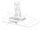
- FIG. 1 is a perspective view of a golf training apparatus, according to an embodiment of the present disclosure
- FIG. 2 is a perspective view of a golf training apparatus, according to an embodiment of the present disclosure
- FIG. 3 is a perspective view of a foot platform of golf training apparatus in an engaged position, according to an embodiment of the present disclosure
- FIG. 4 is a perspective view of a foot platform of golf training apparatus in a collapsed position, according to an embodiment of the present disclosure
- FIG. 5 is an exploded view of a foot platform of golf training apparatus, according to an embodiment of the present disclosure
- FIG. 6 a perspective view of a ball platform of golf training apparatus in an engaged position, according to an embodiment of the present disclosure.
- FIG. 7 is an exploded view of a ball platform of golf training apparatus, according to an embodiment of the present disclosure.
- golf training apparatus 100 is a two-part construction generally comprised of a foot platform 102 and a ball platform 104 .
- a real or artificial hitting surface Regardless of the type of surface, the vast majority of driving rages have the golfer practicing on a substantially flat surface. While golfers typically hit off a flat surface when hitting tee shots, they often experience uneven lies during play due to the numerous hills and valleys on many golf courses. Flat driving range surfaces do not enable the golfer to become accustomed to the necessary balance and hitting technique required to successfully execute uneven golf shots in a consistent manner.
- Golf training apparatus 100 enables the golfer to practice balance and technique for uneven golf shots by manipulating both the plane of the golfer's stance as well as the position of the ball.
- FIG. 2 is a perspective view of foot platform 102 and a ball platform 104 .
- a golfer stands on foot platform 102 when practicing a golf shot, while the golf ball rests on, and is struck from, ball platform 104 . While standing on foot platform 102 , the golfer strikes the golf ball resting on ball platform 104 .
- Foot platform 102 can be manipulated in a variety of positions to simulate uphill, downhill and uneven golf shots.
- Ball platform 104 can be positioned according to a variety of configurations to correspond with the desired position of foot platform 102 to simulate the desired golf ball position, or lie, relative to the user's stance. Foot platform 102 and ball platform 104 may be portable and capable of being set up on a standard driving range surface.
- FIG. 2 shows foot platform 102 in an engaged position, and ball platform 104 in a flat position.
- FIG. 3 is a perspective view of foot platform 102 in an engaged position.
- foot platform 102 comprises a right foot surface 106 a and a left foot surface 106 b .
- the user may face either direction when standing on foot platform 102 , and the designation of “right” and “left” is simply meant to illustrate that the user places each foot on an independent surface.
- support legs 110 are extended to provide support for foot platform 102 and to configure foot platform 102 to a desired height.
- Support leg lock 114 b is engaged to hold support leg 110 in place via support arm 122 .
- Right foot surface 106 a and left foot surface 106 b are configured in a desired position by disengaging adjustment arm lock 114 a and setting adjustment arms 112 to a desired position. The desired position is held in place by engaging adjustment arm lock 114 a .
- Support leg 110 and adjustment arms 112 are coupled to foot platform base 116 , which provides structural support for foot platform 102
- FIG. 4 is a perspective view of foot platform 102 in a collapsed position, according to an embodiment of the present disclosure.
- the user When configured in a collapsed position, the user may easily transport foot platform 102 to and from the practice area.
- support legs 110 are positioned such that they are in contact with foot platform base 116 .
- Wheels 108 are coupled to one end of foot platform base 116
- an extendable handle 118 is coupled to an opposite end of foot platform base 116 .
- the user grips and lifts extendable handle 118 and rolls foot platform 102 via wheels 108 .
- the user may then reconfigure foot platform 102 for use by configuring foot platform 102 as described in FIG. 3 .
- FIG. 5 is an exploded view of foot platform 102 illustrating the construction details of foot platform 102 .
- foot platform 102 is generally comprised of right foot surface 106 a and left foot surface 106 b , which are coupled to foot surface connection 120 .
- Foot surface connection 120 is coupled to foot platform base 116 , and may have a spherical ball bearing fitting at the connection with foot platform base 116 such that foot surface connection 120 may be rotated and pivoted to alter the plane of right foot surface 106 a and left foot surface 106 b .
- Adjustment arms 112 is coupled to foot platform base 116 via adjustment arm lock 114 a , and is coupled to an upper surface of foot surface connection 120 .
- Adjustment arms 112 are operable to provide support for right foot surface 106 a and left foot surface 106 b when right foot surface 106 a and left foot surface 106 b are positioned in a desired configuration.
- adjustment arm lock 114 a locks adjustment arms 112 in place and stabilizes right foot surface 106 a and left foot surface 106 b .
- Support legs 110 are coupled to foot platform base 116 and support arm 122 .
- Support legs 110 and support arm 122 are secured in a desired position by support leg lock 114 b .
- Wheels 108 are coupled to one end of foot platform base 116 , and extendable handle 118 is coupled to an opposite end.
- FIG. 6 is a perspective view of ball platform 104 of golf training apparatus 100 in an engaged position.
- ball platform 104 is generally comprised of ball surface 202 , ball platform support legs 204 , support leg locks 206 , ball surface connector 208 , ball surface support bracket 210 , ball surface adjustment handle 212 , and ball platform base 214 .
- a user extends ball platform support legs 204 to a desired position and locks them in place with support leg locks 206 , and adjusts ball surface 202 to a desired position and locks it in place with ball surface adjustment handle 212 .
- Ball surface 202 may have an artificial turf surface or other synthetic surface to mimic the feel of grass and hold a golf ball in place.
- Ball surface 202 is coupled to ball surface connector 208 .
- Ball surface connector 208 may be configured such that it may enable ball surface 202 to be configured upward, downward and side-to-side.
- Ball surface connector 208 is coupled to ball platform base 214 , and may be stabilized by ball surface support bracket 210 . When adjusted to desired position, a user may place a golf ball on ball surface 202 for practice.
- FIG. 7 is an exploded view of ball platform 104 illustrating the construction details of ball platform 104 .
- Ball surface 202 is coupled to ball surface support plate 216 .
- Ball surface support plate 216 is coupled to ball surface connector 208 .
- Ball surface connector 208 may be comprised of a support plate connector and a platform base connector with a rotatable support means therebetween. The rotatable support means of ball surface connector 208 enables ball surface 202 to be rotatably positioned.
- Ball surface connector 208 may be coupled to ball platform base 214 .
- Ball surface adjustment handle 212 is operably connected to ball surface connector 208 and ball platform base 214 , such that ball surface adjustment handle 212 may lock ball surface connector 208 in a desired position when engaged.
- Ball surface support bracket 210 is coupled to ball platform base 214 and ball surface connector 208 to provide stabilizing support to ball surface connector 208 .
- Ball platform support legs 204 are pivotably coupled to ball platform base 214 .
- Support leg locks 206 are operably connected to ball platform support legs 204 and ball platform base 214 , such that ball platform support legs 204 may be configured to a desired position and locked in place.
- a user may use embodiments of the present disclosure in a variety of use cases, locations, and with or without golf balls.
- the portability of the invention makes it easy to use inside or outside.
- Preferred locations for use include golf driving ranges, back yards, open fields, indoor golf facilities or personal residences.
- Embodiments of the present disclosure solve the problem of poor ball strikes resulting from challenging and/or unusual balance issues.
- the primary use cases for the invention are as an uneven golf lie trainer, a coaching aid to improve swing flaws, and a balance aid device.
- Embodiments of the present disclosure could be utilized to help rehabilitation patients recovering from an injury. In such cases, a patient would stand on the foot platform and go through rehabilitation processes with a physical therapist to improve balance and strength.
- Alternative embodiments may provide for a motorized actuator to automatically adjust the positioning of the foot platform and/or the ball platform.
Abstract
An apparatus to enable golfers to practice uneven golf shots. According to embodiments of the present disclosure, a golf training apparatus is generally comprised of a foot platform and a ball platform that may be dynamically positioned. The golf training apparatus enables the golfer to practice balance and technique for uneven golf shots by manipulating both the plane of the golfer's stance as well as the position of the ball.
Description
The present disclosure relates to the field of golf training aids; in particular, an apparatus to enable golfers to practice uneven golf shots.
Regular practice is essential to achieving competency in the game of golf. Golfing centers offering the golfer hitting areas to practice and improve their game are highly popular. Such practice areas, often called driving ranges, often employ synthetic mats off of which a ball may be hit with a club. Unfortunately, many artificial golf hitting areas do not allow for the golfer to control the horizontal and vertical orientation of the golf ball to better emulate the conditions golfers experience on a golf course.
Various prior art solutions exist to create a practice device where the surface thereof can be adjusted in some way so as to vary its angle relative to the horizontal in order to provide a more realistic practice surface for golfers. These devices can be difficult to operate, and are usually so heavy that they must essentially remain in one location because of the difficulty in moving them. They may require complicated and expensive hydraulic mechanisms to operate, electrical power for motors associated with the device, and metal framework to support the weight of the platform surface as well as the golfer when practicing.
Various devices for tilting golf practice platforms have been proposed. However, no solution currently exists that enables the golfer to independently alter the orientation and plane of both the golf ball and the golfer's stance. Nor is there a solution that provides these features in a light weight and portable construction. What is needed, therefore, is a golf practice apparatus that is both portable, and capable of manipulating the orientation and plane of a golfer's stance and the position of the golf ball. The inventors have developed a solution that is embodied by the present invention, which is described in detail below.
The following presents a simplified summary of some embodiments of the invention in order to provide a basic understanding of the invention. This summary is not an extensive overview of the invention. It is not intended to identify key/critical elements of the invention or to delineate the scope of the invention. Its sole purpose is to present some embodiments of the invention in a simplified form as a prelude to the more detailed description that is presented later.
An embodiment of the present invention is a golf training apparatus comprising a foot platform, the foot platform comprising a right foot surface and a left foot surface, a right foot adjustment means and a left foot adjustment means operably engaged with the right foot surface and the left foot surface, and a foot platform base coupled to the right foot adjustment means and the left foot adjustment means; and, a ball platform, the ball platform comprising a ball surface, a ball surface adjustment means coupled to the ball surface, and a ball platform base coupled to the ball surface adjustment means.
Another embodiment of the present invention is golf training apparatus comprising a foot platform, the foot platform comprising a right foot surface and a left foot surface, a right foot adjustment means and a left foot adjustment means operably engaged with the right foot surface and the left foot surface, a foot platform base coupled to the right foot adjustment means and the left foot adjustment means, and an adjustable foot platform support means coupled to the foot platform base; and, a ball platform, the ball platform comprising a ball surface, a ball surface adjustment means coupled to the ball surface, a ball platform base coupled to the ball surface adjustment mean, and an adjustable ball platform support means coupled to the ball platform base.
Yet another embodiment of the present invention is a golf training apparatus comprising a foot platform, the foot platform comprising a right foot surface and a left foot surface, a right foot adjustment means and a left foot adjustment means operably coupled to the right foot surface and the left foot surface, a foot platform base coupled to the right foot adjustment means and the left foot adjustment means, an adjustable foot platform support means coupled to the foot platform base, and at least two wheels coupled to the foot platform base; and, a ball platform, the ball platform comprising a ball surface, a ball surface adjustment means coupled to the ball surface, a ball platform base coupled to the ball surface adjustment means, and an adjustable ball platform support means coupled to the ball platform base.
The foregoing has outlined rather broadly the more pertinent and important features of the present invention so that the detailed description of the invention that follows may be better understood and so that the present contribution to the art can be more fully appreciated. Additional features of the invention will be described hereinafter which form the subject of the claims of the invention. It should be appreciated by those skilled in the art that the conception and the disclosed specific methods and structures may be readily utilized as a basis for modifying or designing other structures for carrying out the same purposes of the present invention. It should be realized by those skilled in the art that such equivalent structures do not depart from the spirit and scope of the invention as set forth in the appended claims.
The above and other objects, features and advantages of the present disclosure will be more apparent from the following detailed description taken in conjunction with the accompanying drawings, in which:
Exemplary embodiments are described herein to provide a detailed description of the present disclosure. Variations of these embodiments will be apparent to those of skill in the art. Moreover, certain terminology is used in the following description for convenience only and is not limiting. For example, the words “right,” “left,” “top,” “bottom,” “upper,” “lower,” “inner” and “outer” designate directions in the drawings to which reference is made. The word “a” is defined to mean “at least one.” The terminology includes the words above specifically mentioned, derivatives thereof, and words of similar import.
Referring now to FIG. 1 , a perspective view of a golf training apparatus 100 is shown. According to an embodiment, golf training apparatus 100 is a two-part construction generally comprised of a foot platform 102 and a ball platform 104. Typically golfers practice at driving ranges with either a real or artificial hitting surface. Regardless of the type of surface, the vast majority of driving rages have the golfer practicing on a substantially flat surface. While golfers typically hit off a flat surface when hitting tee shots, they often experience uneven lies during play due to the numerous hills and valleys on many golf courses. Flat driving range surfaces do not enable the golfer to become accustomed to the necessary balance and hitting technique required to successfully execute uneven golf shots in a consistent manner. Golf training apparatus 100 enables the golfer to practice balance and technique for uneven golf shots by manipulating both the plane of the golfer's stance as well as the position of the ball.
Ball surface adjustment handle 212 is operably connected to ball surface connector 208 and ball platform base 214, such that ball surface adjustment handle 212 may lock ball surface connector 208 in a desired position when engaged. Ball surface support bracket 210 is coupled to ball platform base 214 and ball surface connector 208 to provide stabilizing support to ball surface connector 208. Ball platform support legs 204 are pivotably coupled to ball platform base 214. Support leg locks 206 are operably connected to ball platform support legs 204 and ball platform base 214, such that ball platform support legs 204 may be configured to a desired position and locked in place.
A user may use embodiments of the present disclosure in a variety of use cases, locations, and with or without golf balls. The portability of the invention makes it easy to use inside or outside. Preferred locations for use include golf driving ranges, back yards, open fields, indoor golf facilities or personal residences. Embodiments of the present disclosure solve the problem of poor ball strikes resulting from challenging and/or unusual balance issues. The primary use cases for the invention are as an uneven golf lie trainer, a coaching aid to improve swing flaws, and a balance aid device.
Embodiments of the present disclosure could be utilized to help rehabilitation patients recovering from an injury. In such cases, a patient would stand on the foot platform and go through rehabilitation processes with a physical therapist to improve balance and strength. Alternative embodiments may provide for a motorized actuator to automatically adjust the positioning of the foot platform and/or the ball platform.
The present disclosure includes that contained in the appended claims as well as that of the foregoing description. Although this invention has been described in its exemplary forms with a certain degree of particularity, it is understood that the present disclosure of has been made only by way of example and numerous changes in the details of construction and combination and arrangement of parts may be employed without departing from the spirit and scope of the invention.
Claims (4)
1. A golf training apparatus comprising:
a foot platform, the foot platform comprising an independent right foot surface and an independent left foot surface, a right foot adjustment means and a left foot adjustment means operably engaged with the independent right foot surface and the independent left foot surface such that the independent right foot surface and the independent left foot surface may be independently configured to a desired position, a foot platform base coupled to the right foot adjustment means and the left foot adjustment means, an adjustable foot platform support means coupled to the foot platform base, and at least two wheels coupled to the foot platform base, the adjustable foot platform support means being configured to elevate the at least two wheels from the ground and selectively position the foot platform base to a desired height; and,
a ball platform, the ball platform comprising a ball surface, a ball surface adjustment means coupled to the ball surface, a ball platform base coupled to the ball surface adjustment means, and an adjustable ball platform support means coupled to the ball platform base.
2. The golf training apparatus of claim 1 further comprising a locking means coupled to the right foot adjustment means and the left foot adjustment means.
3. The golf training apparatus of claim 1 further comprising an extendable handle coupled to the foot platform base.
4. The golf training apparatus of claim 1 further comprising a handle operably coupled to the ball surface adjustment means.
Priority Applications (1)
| Application Number | Priority Date | Filing Date | Title |
|---|---|---|---|
| US15/043,746 US9802100B2 (en) | 2016-02-15 | 2016-02-15 | Dynamic positioning golf training apparatus |
Applications Claiming Priority (1)
| Application Number | Priority Date | Filing Date | Title |
|---|---|---|---|
| US15/043,746 US9802100B2 (en) | 2016-02-15 | 2016-02-15 | Dynamic positioning golf training apparatus |
Publications (2)
| Publication Number | Publication Date |
|---|---|
| US20170232321A1 US20170232321A1 (en) | 2017-08-17 |
| US9802100B2 true US9802100B2 (en) | 2017-10-31 |
Family
ID=59560031
Family Applications (1)
| Application Number | Title | Priority Date | Filing Date |
|---|---|---|---|
| US15/043,746 Active US9802100B2 (en) | 2016-02-15 | 2016-02-15 | Dynamic positioning golf training apparatus |
Country Status (1)
| Country | Link |
|---|---|
| US (1) | US9802100B2 (en) |
Cited By (1)
| Publication number | Priority date | Publication date | Assignee | Title |
|---|---|---|---|---|
| US11465026B2 (en) | 2019-04-04 | 2022-10-11 | Perfection Platforms, Ltd. | Apparatus and methods for golf stroke training |
Citations (16)
| Publication number | Priority date | Publication date | Assignee | Title |
|---|---|---|---|---|
| US2879996A (en) * | 1957-01-07 | 1959-03-31 | Albrecht M Lederer | Golf practicing machine |
| US5720670A (en) | 1994-09-16 | 1998-02-24 | Griffin Intellectual Property Development Corporation | Golf practice apparatus |
| US5820478A (en) | 1997-07-11 | 1998-10-13 | Slopemaster Golf, Inc. | Powered tiltable platform |
| US5944615A (en) * | 1998-08-11 | 1999-08-31 | Lee; Bum Ho | Golf practice apparatus |
| US5957788A (en) * | 1997-04-01 | 1999-09-28 | Eze; Obi Walter | Sports practice apparatus |
| US6312345B1 (en) | 2000-05-12 | 2001-11-06 | David T. Pelz | Golf practice platform for a variety of golf shots |
| US20020128084A1 (en) | 2001-02-23 | 2002-09-12 | Lee Sang Chul | Inclination-adjustable golf training device |
| US6450895B1 (en) * | 2000-06-05 | 2002-09-17 | Denny J. Galluzzo, Jr. | Golf practice device with adjustable golf ball tee platform and adjustable leg stance platform |
| US6663498B2 (en) | 1999-05-14 | 2003-12-16 | Arthur R. Stipan | Tiltable golf platform |
| US20040110570A1 (en) | 2000-11-22 | 2004-06-10 | Hutchon Bruce Gordon Imrie | Tiltable golf platform |
| US20050113182A1 (en) * | 2003-11-26 | 2005-05-26 | Kim Sung T. | Golf shot practice apparatus |
| US20060205528A1 (en) * | 2003-04-28 | 2006-09-14 | Mcmillan Vern | Training device for golfers |
| US20090023523A1 (en) * | 2007-07-20 | 2009-01-22 | Gary Poillucci | Apparatus and method for collecting projectile game pieces |
| US7993249B1 (en) * | 2005-11-01 | 2011-08-09 | Fassl Michael J | Swing enhancement exercise device with resilient resistance |
| US8496538B1 (en) | 2011-01-11 | 2013-07-30 | Nelson Tyler | Tilting golf practice platform |
| US20150005083A1 (en) | 2013-06-28 | 2015-01-01 | Chen-Chung Tang | Tiltable/adjustable golf practice device |
-
2016
- 2016-02-15 US US15/043,746 patent/US9802100B2/en active Active
Patent Citations (17)
| Publication number | Priority date | Publication date | Assignee | Title |
|---|---|---|---|---|
| US2879996A (en) * | 1957-01-07 | 1959-03-31 | Albrecht M Lederer | Golf practicing machine |
| US5720670A (en) | 1994-09-16 | 1998-02-24 | Griffin Intellectual Property Development Corporation | Golf practice apparatus |
| US5957788A (en) * | 1997-04-01 | 1999-09-28 | Eze; Obi Walter | Sports practice apparatus |
| US5820478A (en) | 1997-07-11 | 1998-10-13 | Slopemaster Golf, Inc. | Powered tiltable platform |
| US5944615A (en) * | 1998-08-11 | 1999-08-31 | Lee; Bum Ho | Golf practice apparatus |
| US6663498B2 (en) | 1999-05-14 | 2003-12-16 | Arthur R. Stipan | Tiltable golf platform |
| US6312345B1 (en) | 2000-05-12 | 2001-11-06 | David T. Pelz | Golf practice platform for a variety of golf shots |
| US6450895B1 (en) * | 2000-06-05 | 2002-09-17 | Denny J. Galluzzo, Jr. | Golf practice device with adjustable golf ball tee platform and adjustable leg stance platform |
| US20040110570A1 (en) | 2000-11-22 | 2004-06-10 | Hutchon Bruce Gordon Imrie | Tiltable golf platform |
| US20020128084A1 (en) | 2001-02-23 | 2002-09-12 | Lee Sang Chul | Inclination-adjustable golf training device |
| US20060205528A1 (en) * | 2003-04-28 | 2006-09-14 | Mcmillan Vern | Training device for golfers |
| US20050113182A1 (en) * | 2003-11-26 | 2005-05-26 | Kim Sung T. | Golf shot practice apparatus |
| US7993249B1 (en) * | 2005-11-01 | 2011-08-09 | Fassl Michael J | Swing enhancement exercise device with resilient resistance |
| US20090023523A1 (en) * | 2007-07-20 | 2009-01-22 | Gary Poillucci | Apparatus and method for collecting projectile game pieces |
| US8496538B1 (en) | 2011-01-11 | 2013-07-30 | Nelson Tyler | Tilting golf practice platform |
| US20150005083A1 (en) | 2013-06-28 | 2015-01-01 | Chen-Chung Tang | Tiltable/adjustable golf practice device |
| US9011264B2 (en) | 2013-06-28 | 2015-04-21 | Chen-Chung Tang | Tiltable/adjustable golf practice device |
Cited By (1)
| Publication number | Priority date | Publication date | Assignee | Title |
|---|---|---|---|---|
| US11465026B2 (en) | 2019-04-04 | 2022-10-11 | Perfection Platforms, Ltd. | Apparatus and methods for golf stroke training |
Also Published As
| Publication number | Publication date |
|---|---|
| US20170232321A1 (en) | 2017-08-17 |
Similar Documents
| Publication | Publication Date | Title |
|---|---|---|
| US7658689B2 (en) | Ultimate defender | |
| US8777781B2 (en) | Variable gravity training device | |
| US8801548B2 (en) | Tennis and golf training device having an adjustable hoop | |
| US10953298B1 (en) | Basketball trainer device | |
| US20130344996A1 (en) | Soccer Training Device, Method of Use and System | |
| US8133125B2 (en) | Leverage discs | |
| CN106075862B (en) | A kind of golf practice device and training court analogy method | |
| US20130040762A1 (en) | Tennis, golf and basketball training device having an adjustable hoop | |
| US20160375334A1 (en) | Rotating training device for kicking a soccer ball or football | |
| US20050288120A1 (en) | Dual sport swing training aid and method of using | |
| US20120122602A1 (en) | Golf training method and apparatus | |
| US20210379460A1 (en) | Hockey training device | |
| US8197364B2 (en) | Training device for beach volleyball players | |
| US20220016492A1 (en) | Basketball training apparatus and method for using same in shooting a basketball | |
| US9802100B2 (en) | Dynamic positioning golf training apparatus | |
| US7056237B2 (en) | Portable basketball rebound apparatus and method | |
| US7025689B2 (en) | Adjustable athletic swing training aid | |
| US10478701B2 (en) | Golf ball stopping device for simulating a putting green hole | |
| US20060122003A1 (en) | Portable golf swing position training aid kit | |
| US20110165956A1 (en) | Smart Golf Club | |
| US10661140B2 (en) | Golf-training apparatus | |
| KR20090117562A (en) | Plate for practicing golf-swing with vertical actuator | |
| KR200373620Y1 (en) | Carrying putting practice device that is possible direction indicate of shot | |
| JP2006524516A (en) | Golfer training device | |
| US10702752B2 (en) | Golf ball stopping device for simulating a putting green hole |
Legal Events
| Date | Code | Title | Description |
|---|---|---|---|
| STCF | Information on status: patent grant |
Free format text: PATENTED CASE |
|
| MAFP | Maintenance fee payment |
Free format text: PAYMENT OF MAINTENANCE FEE, 4TH YEAR, MICRO ENTITY (ORIGINAL EVENT CODE: M3551); ENTITY STATUS OF PATENT OWNER: MICROENTITY Year of fee payment: 4 |