US9801407B2 - Compression system for producing a high density compact product - Google Patents
Compression system for producing a high density compact product Download PDFInfo
- Publication number
- US9801407B2 US9801407B2 US14/182,094 US201414182094A US9801407B2 US 9801407 B2 US9801407 B2 US 9801407B2 US 201414182094 A US201414182094 A US 201414182094A US 9801407 B2 US9801407 B2 US 9801407B2
- Authority
- US
- United States
- Prior art keywords
- treated material
- die
- compression
- treated
- distiller
- Prior art date
- Legal status (The legal status is an assumption and is not a legal conclusion. Google has not performed a legal analysis and makes no representation as to the accuracy of the status listed.)
- Expired - Fee Related, expires
Links
Images


Classifications
-
- A—HUMAN NECESSITIES
- A23—FOODS OR FOODSTUFFS; TREATMENT THEREOF, NOT COVERED BY OTHER CLASSES
- A23N—MACHINES OR APPARATUS FOR TREATING HARVESTED FRUIT, VEGETABLES OR FLOWER BULBS IN BULK, NOT OTHERWISE PROVIDED FOR; PEELING VEGETABLES OR FRUIT IN BULK; APPARATUS FOR PREPARING ANIMAL FEEDING- STUFFS
- A23N17/00—Apparatus specially adapted for preparing animal feeding-stuffs
- A23N17/005—Apparatus specially adapted for preparing animal feeding-stuffs for shaping by moulding, extrusion, pressing, e.g. pellet-mills
-
- A—HUMAN NECESSITIES
- A23—FOODS OR FOODSTUFFS; TREATMENT THEREOF, NOT COVERED BY OTHER CLASSES
- A23K—FODDER
- A23K10/00—Animal feeding-stuffs
- A23K10/30—Animal feeding-stuffs from material of plant origin, e.g. roots, seeds or hay; from material of fungal origin, e.g. mushrooms
- A23K10/37—Animal feeding-stuffs from material of plant origin, e.g. roots, seeds or hay; from material of fungal origin, e.g. mushrooms from waste material
- A23K10/38—Animal feeding-stuffs from material of plant origin, e.g. roots, seeds or hay; from material of fungal origin, e.g. mushrooms from waste material from distillers' or brewers' waste
-
- A23P1/12—
-
- A—HUMAN NECESSITIES
- A23—FOODS OR FOODSTUFFS; TREATMENT THEREOF, NOT COVERED BY OTHER CLASSES
- A23P—SHAPING OR WORKING OF FOODSTUFFS, NOT FULLY COVERED BY A SINGLE OTHER SUBCLASS
- A23P10/00—Shaping or working of foodstuffs characterised by the products
- A23P10/20—Agglomerating; Granulating; Tabletting
- A23P10/25—Agglomeration or granulation by extrusion or by pressing, e.g. through small holes, through sieves or between surfaces
-
- A—HUMAN NECESSITIES
- A23—FOODS OR FOODSTUFFS; TREATMENT THEREOF, NOT COVERED BY OTHER CLASSES
- A23P—SHAPING OR WORKING OF FOODSTUFFS, NOT FULLY COVERED BY A SINGLE OTHER SUBCLASS
- A23P10/00—Shaping or working of foodstuffs characterised by the products
- A23P10/20—Agglomerating; Granulating; Tabletting
- A23P10/28—Tabletting; Making food bars by compression of a dry powdered mixture
-
- A—HUMAN NECESSITIES
- A23—FOODS OR FOODSTUFFS; TREATMENT THEREOF, NOT COVERED BY OTHER CLASSES
- A23P—SHAPING OR WORKING OF FOODSTUFFS, NOT FULLY COVERED BY A SINGLE OTHER SUBCLASS
- A23P30/00—Shaping or working of foodstuffs characterised by the process or apparatus
- A23P30/20—Extruding
-
- B29C47/0011—
-
- B29C47/0023—
-
- B29C47/30—
-
- B29C47/38—
-
- B29C47/6018—
-
- B29C47/827—
-
- B29C47/866—
-
- B29C47/8815—
-
- B29C47/90—
-
- B29C47/92—
-
- B—PERFORMING OPERATIONS; TRANSPORTING
- B29—WORKING OF PLASTICS; WORKING OF SUBSTANCES IN A PLASTIC STATE IN GENERAL
- B29C—SHAPING OR JOINING OF PLASTICS; SHAPING OF MATERIAL IN A PLASTIC STATE, NOT OTHERWISE PROVIDED FOR; AFTER-TREATMENT OF THE SHAPED PRODUCTS, e.g. REPAIRING
- B29C48/00—Extrusion moulding, i.e. expressing the moulding material through a die or nozzle which imparts the desired form; Apparatus therefor
- B29C48/03—Extrusion moulding, i.e. expressing the moulding material through a die or nozzle which imparts the desired form; Apparatus therefor characterised by the shape of the extruded material at extrusion
- B29C48/05—Filamentary, e.g. strands
-
- B—PERFORMING OPERATIONS; TRANSPORTING
- B29—WORKING OF PLASTICS; WORKING OF SUBSTANCES IN A PLASTIC STATE IN GENERAL
- B29C—SHAPING OR JOINING OF PLASTICS; SHAPING OF MATERIAL IN A PLASTIC STATE, NOT OTHERWISE PROVIDED FOR; AFTER-TREATMENT OF THE SHAPED PRODUCTS, e.g. REPAIRING
- B29C48/00—Extrusion moulding, i.e. expressing the moulding material through a die or nozzle which imparts the desired form; Apparatus therefor
- B29C48/03—Extrusion moulding, i.e. expressing the moulding material through a die or nozzle which imparts the desired form; Apparatus therefor characterised by the shape of the extruded material at extrusion
- B29C48/09—Articles with cross-sections having partially or fully enclosed cavities, e.g. pipes or channels
-
- B—PERFORMING OPERATIONS; TRANSPORTING
- B29—WORKING OF PLASTICS; WORKING OF SUBSTANCES IN A PLASTIC STATE IN GENERAL
- B29C—SHAPING OR JOINING OF PLASTICS; SHAPING OF MATERIAL IN A PLASTIC STATE, NOT OTHERWISE PROVIDED FOR; AFTER-TREATMENT OF THE SHAPED PRODUCTS, e.g. REPAIRING
- B29C48/00—Extrusion moulding, i.e. expressing the moulding material through a die or nozzle which imparts the desired form; Apparatus therefor
- B29C48/25—Component parts, details or accessories; Auxiliary operations
- B29C48/30—Extrusion nozzles or dies
- B29C48/345—Extrusion nozzles comprising two or more adjacently arranged ports, for simultaneously extruding multiple strands, e.g. for pelletising
-
- B—PERFORMING OPERATIONS; TRANSPORTING
- B29—WORKING OF PLASTICS; WORKING OF SUBSTANCES IN A PLASTIC STATE IN GENERAL
- B29C—SHAPING OR JOINING OF PLASTICS; SHAPING OF MATERIAL IN A PLASTIC STATE, NOT OTHERWISE PROVIDED FOR; AFTER-TREATMENT OF THE SHAPED PRODUCTS, e.g. REPAIRING
- B29C48/00—Extrusion moulding, i.e. expressing the moulding material through a die or nozzle which imparts the desired form; Apparatus therefor
- B29C48/25—Component parts, details or accessories; Auxiliary operations
- B29C48/36—Means for plasticising or homogenising the moulding material or forcing it through the nozzle or die
- B29C48/395—Means for plasticising or homogenising the moulding material or forcing it through the nozzle or die using screws surrounded by a cooperating barrel, e.g. single screw extruders
-
- B—PERFORMING OPERATIONS; TRANSPORTING
- B29—WORKING OF PLASTICS; WORKING OF SUBSTANCES IN A PLASTIC STATE IN GENERAL
- B29C—SHAPING OR JOINING OF PLASTICS; SHAPING OF MATERIAL IN A PLASTIC STATE, NOT OTHERWISE PROVIDED FOR; AFTER-TREATMENT OF THE SHAPED PRODUCTS, e.g. REPAIRING
- B29C48/00—Extrusion moulding, i.e. expressing the moulding material through a die or nozzle which imparts the desired form; Apparatus therefor
- B29C48/25—Component parts, details or accessories; Auxiliary operations
- B29C48/36—Means for plasticising or homogenising the moulding material or forcing it through the nozzle or die
- B29C48/50—Details of extruders
- B29C48/505—Screws
- B29C48/53—Screws having a varying channel depth, e.g. varying the diameter of the longitudinal screw trunk
-
- B—PERFORMING OPERATIONS; TRANSPORTING
- B29—WORKING OF PLASTICS; WORKING OF SUBSTANCES IN A PLASTIC STATE IN GENERAL
- B29C—SHAPING OR JOINING OF PLASTICS; SHAPING OF MATERIAL IN A PLASTIC STATE, NOT OTHERWISE PROVIDED FOR; AFTER-TREATMENT OF THE SHAPED PRODUCTS, e.g. REPAIRING
- B29C48/00—Extrusion moulding, i.e. expressing the moulding material through a die or nozzle which imparts the desired form; Apparatus therefor
- B29C48/25—Component parts, details or accessories; Auxiliary operations
- B29C48/78—Thermal treatment of the extrusion moulding material or of preformed parts or layers, e.g. by heating or cooling
- B29C48/86—Thermal treatment of the extrusion moulding material or of preformed parts or layers, e.g. by heating or cooling at the nozzle zone
- B29C48/872—Thermal treatment of the extrusion moulding material or of preformed parts or layers, e.g. by heating or cooling at the nozzle zone characterised by differential heating or cooling
-
- B—PERFORMING OPERATIONS; TRANSPORTING
- B29—WORKING OF PLASTICS; WORKING OF SUBSTANCES IN A PLASTIC STATE IN GENERAL
- B29C—SHAPING OR JOINING OF PLASTICS; SHAPING OF MATERIAL IN A PLASTIC STATE, NOT OTHERWISE PROVIDED FOR; AFTER-TREATMENT OF THE SHAPED PRODUCTS, e.g. REPAIRING
- B29C48/00—Extrusion moulding, i.e. expressing the moulding material through a die or nozzle which imparts the desired form; Apparatus therefor
- B29C48/25—Component parts, details or accessories; Auxiliary operations
- B29C48/78—Thermal treatment of the extrusion moulding material or of preformed parts or layers, e.g. by heating or cooling
- B29C48/875—Thermal treatment of the extrusion moulding material or of preformed parts or layers, e.g. by heating or cooling for achieving a non-uniform temperature distribution, e.g. using barrels having both cooling and heating zones
-
- B—PERFORMING OPERATIONS; TRANSPORTING
- B29—WORKING OF PLASTICS; WORKING OF SUBSTANCES IN A PLASTIC STATE IN GENERAL
- B29C—SHAPING OR JOINING OF PLASTICS; SHAPING OF MATERIAL IN A PLASTIC STATE, NOT OTHERWISE PROVIDED FOR; AFTER-TREATMENT OF THE SHAPED PRODUCTS, e.g. REPAIRING
- B29C48/00—Extrusion moulding, i.e. expressing the moulding material through a die or nozzle which imparts the desired form; Apparatus therefor
- B29C48/25—Component parts, details or accessories; Auxiliary operations
- B29C48/88—Thermal treatment of the stream of extruded material, e.g. cooling
- B29C48/90—Thermal treatment of the stream of extruded material, e.g. cooling with calibration or sizing, i.e. combined with fixing or setting of the final dimensions of the extruded article
-
- B—PERFORMING OPERATIONS; TRANSPORTING
- B29—WORKING OF PLASTICS; WORKING OF SUBSTANCES IN A PLASTIC STATE IN GENERAL
- B29C—SHAPING OR JOINING OF PLASTICS; SHAPING OF MATERIAL IN A PLASTIC STATE, NOT OTHERWISE PROVIDED FOR; AFTER-TREATMENT OF THE SHAPED PRODUCTS, e.g. REPAIRING
- B29C48/00—Extrusion moulding, i.e. expressing the moulding material through a die or nozzle which imparts the desired form; Apparatus therefor
- B29C48/25—Component parts, details or accessories; Auxiliary operations
- B29C48/88—Thermal treatment of the stream of extruded material, e.g. cooling
- B29C48/911—Cooling
-
- B—PERFORMING OPERATIONS; TRANSPORTING
- B29—WORKING OF PLASTICS; WORKING OF SUBSTANCES IN A PLASTIC STATE IN GENERAL
- B29C—SHAPING OR JOINING OF PLASTICS; SHAPING OF MATERIAL IN A PLASTIC STATE, NOT OTHERWISE PROVIDED FOR; AFTER-TREATMENT OF THE SHAPED PRODUCTS, e.g. REPAIRING
- B29C48/00—Extrusion moulding, i.e. expressing the moulding material through a die or nozzle which imparts the desired form; Apparatus therefor
- B29C48/25—Component parts, details or accessories; Auxiliary operations
- B29C48/92—Measuring, controlling or regulating
-
- F—MECHANICAL ENGINEERING; LIGHTING; HEATING; WEAPONS; BLASTING
- F26—DRYING
- F26B—DRYING SOLID MATERIALS OR OBJECTS BY REMOVING LIQUID THEREFROM
- F26B17/00—Machines or apparatus for drying materials in loose, plastic, or fluidised form, e.g. granules, staple fibres, with progressive movement
- F26B17/18—Machines or apparatus for drying materials in loose, plastic, or fluidised form, e.g. granules, staple fibres, with progressive movement with movement performed by rotating helical blades or other rotary conveyors which may be heated moving materials in stationary chambers, e.g. troughs
- F26B17/20—Machines or apparatus for drying materials in loose, plastic, or fluidised form, e.g. granules, staple fibres, with progressive movement with movement performed by rotating helical blades or other rotary conveyors which may be heated moving materials in stationary chambers, e.g. troughs the axis of rotation being horizontal or slightly inclined
-
- F—MECHANICAL ENGINEERING; LIGHTING; HEATING; WEAPONS; BLASTING
- F26—DRYING
- F26B—DRYING SOLID MATERIALS OR OBJECTS BY REMOVING LIQUID THEREFROM
- F26B5/00—Drying solid materials or objects by processes not involving the application of heat
- F26B5/14—Drying solid materials or objects by processes not involving the application of heat by applying pressure, e.g. wringing; by brushing; by wiping
-
- A—HUMAN NECESSITIES
- A23—FOODS OR FOODSTUFFS; TREATMENT THEREOF, NOT COVERED BY OTHER CLASSES
- A23P—SHAPING OR WORKING OF FOODSTUFFS, NOT FULLY COVERED BY A SINGLE OTHER SUBCLASS
- A23P10/00—Shaping or working of foodstuffs characterised by the products
- A23P10/20—Agglomerating; Granulating; Tabletting
-
- B29C2947/92—
-
- B29C2947/92019—
-
- B29C2947/92209—
-
- B29C2947/92428—
-
- B29C2947/9259—
-
- B29C2947/926—
-
- B29C2947/92638—
-
- B29C2947/92704—
-
- B29C2947/92923—
-
- B—PERFORMING OPERATIONS; TRANSPORTING
- B29—WORKING OF PLASTICS; WORKING OF SUBSTANCES IN A PLASTIC STATE IN GENERAL
- B29C—SHAPING OR JOINING OF PLASTICS; SHAPING OF MATERIAL IN A PLASTIC STATE, NOT OTHERWISE PROVIDED FOR; AFTER-TREATMENT OF THE SHAPED PRODUCTS, e.g. REPAIRING
- B29C2948/00—Indexing scheme relating to extrusion moulding
- B29C2948/92—Measuring, controlling or regulating
- B29C2948/92009—Measured parameter
- B29C2948/92019—Pressure
-
- B—PERFORMING OPERATIONS; TRANSPORTING
- B29—WORKING OF PLASTICS; WORKING OF SUBSTANCES IN A PLASTIC STATE IN GENERAL
- B29C—SHAPING OR JOINING OF PLASTICS; SHAPING OF MATERIAL IN A PLASTIC STATE, NOT OTHERWISE PROVIDED FOR; AFTER-TREATMENT OF THE SHAPED PRODUCTS, e.g. REPAIRING
- B29C2948/00—Indexing scheme relating to extrusion moulding
- B29C2948/92—Measuring, controlling or regulating
- B29C2948/92009—Measured parameter
- B29C2948/92209—Temperature
-
- B—PERFORMING OPERATIONS; TRANSPORTING
- B29—WORKING OF PLASTICS; WORKING OF SUBSTANCES IN A PLASTIC STATE IN GENERAL
- B29C—SHAPING OR JOINING OF PLASTICS; SHAPING OF MATERIAL IN A PLASTIC STATE, NOT OTHERWISE PROVIDED FOR; AFTER-TREATMENT OF THE SHAPED PRODUCTS, e.g. REPAIRING
- B29C2948/00—Indexing scheme relating to extrusion moulding
- B29C2948/92—Measuring, controlling or regulating
- B29C2948/92323—Location or phase of measurement
- B29C2948/92428—Calibration, after-treatment, or cooling zone
-
- B—PERFORMING OPERATIONS; TRANSPORTING
- B29—WORKING OF PLASTICS; WORKING OF SUBSTANCES IN A PLASTIC STATE IN GENERAL
- B29C—SHAPING OR JOINING OF PLASTICS; SHAPING OF MATERIAL IN A PLASTIC STATE, NOT OTHERWISE PROVIDED FOR; AFTER-TREATMENT OF THE SHAPED PRODUCTS, e.g. REPAIRING
- B29C2948/00—Indexing scheme relating to extrusion moulding
- B29C2948/92—Measuring, controlling or regulating
- B29C2948/92504—Controlled parameter
- B29C2948/9258—Velocity
- B29C2948/9259—Angular velocity
-
- B—PERFORMING OPERATIONS; TRANSPORTING
- B29—WORKING OF PLASTICS; WORKING OF SUBSTANCES IN A PLASTIC STATE IN GENERAL
- B29C—SHAPING OR JOINING OF PLASTICS; SHAPING OF MATERIAL IN A PLASTIC STATE, NOT OTHERWISE PROVIDED FOR; AFTER-TREATMENT OF THE SHAPED PRODUCTS, e.g. REPAIRING
- B29C2948/00—Indexing scheme relating to extrusion moulding
- B29C2948/92—Measuring, controlling or regulating
- B29C2948/92504—Controlled parameter
- B29C2948/9258—Velocity
- B29C2948/926—Flow or feed rate
-
- B—PERFORMING OPERATIONS; TRANSPORTING
- B29—WORKING OF PLASTICS; WORKING OF SUBSTANCES IN A PLASTIC STATE IN GENERAL
- B29C—SHAPING OR JOINING OF PLASTICS; SHAPING OF MATERIAL IN A PLASTIC STATE, NOT OTHERWISE PROVIDED FOR; AFTER-TREATMENT OF THE SHAPED PRODUCTS, e.g. REPAIRING
- B29C2948/00—Indexing scheme relating to extrusion moulding
- B29C2948/92—Measuring, controlling or regulating
- B29C2948/92504—Controlled parameter
- B29C2948/92609—Dimensions
- B29C2948/92638—Length
-
- B—PERFORMING OPERATIONS; TRANSPORTING
- B29—WORKING OF PLASTICS; WORKING OF SUBSTANCES IN A PLASTIC STATE IN GENERAL
- B29C—SHAPING OR JOINING OF PLASTICS; SHAPING OF MATERIAL IN A PLASTIC STATE, NOT OTHERWISE PROVIDED FOR; AFTER-TREATMENT OF THE SHAPED PRODUCTS, e.g. REPAIRING
- B29C2948/00—Indexing scheme relating to extrusion moulding
- B29C2948/92—Measuring, controlling or regulating
- B29C2948/92504—Controlled parameter
- B29C2948/92704—Temperature
-
- B—PERFORMING OPERATIONS; TRANSPORTING
- B29—WORKING OF PLASTICS; WORKING OF SUBSTANCES IN A PLASTIC STATE IN GENERAL
- B29C—SHAPING OR JOINING OF PLASTICS; SHAPING OF MATERIAL IN A PLASTIC STATE, NOT OTHERWISE PROVIDED FOR; AFTER-TREATMENT OF THE SHAPED PRODUCTS, e.g. REPAIRING
- B29C2948/00—Indexing scheme relating to extrusion moulding
- B29C2948/92—Measuring, controlling or regulating
- B29C2948/92819—Location or phase of control
- B29C2948/92923—Calibration, after-treatment or cooling zone
-
- B29C47/0016—
-
- B29C47/12—
-
- B29C47/20—
-
- B29C47/402—
-
- B29C47/60—
-
- B29C47/884—
-
- B29C47/8895—
-
- B29C47/904—
-
- B—PERFORMING OPERATIONS; TRANSPORTING
- B29—WORKING OF PLASTICS; WORKING OF SUBSTANCES IN A PLASTIC STATE IN GENERAL
- B29C—SHAPING OR JOINING OF PLASTICS; SHAPING OF MATERIAL IN A PLASTIC STATE, NOT OTHERWISE PROVIDED FOR; AFTER-TREATMENT OF THE SHAPED PRODUCTS, e.g. REPAIRING
- B29C48/00—Extrusion moulding, i.e. expressing the moulding material through a die or nozzle which imparts the desired form; Apparatus therefor
- B29C48/03—Extrusion moulding, i.e. expressing the moulding material through a die or nozzle which imparts the desired form; Apparatus therefor characterised by the shape of the extruded material at extrusion
- B29C48/04—Particle-shaped
-
- B—PERFORMING OPERATIONS; TRANSPORTING
- B29—WORKING OF PLASTICS; WORKING OF SUBSTANCES IN A PLASTIC STATE IN GENERAL
- B29C—SHAPING OR JOINING OF PLASTICS; SHAPING OF MATERIAL IN A PLASTIC STATE, NOT OTHERWISE PROVIDED FOR; AFTER-TREATMENT OF THE SHAPED PRODUCTS, e.g. REPAIRING
- B29C48/00—Extrusion moulding, i.e. expressing the moulding material through a die or nozzle which imparts the desired form; Apparatus therefor
- B29C48/03—Extrusion moulding, i.e. expressing the moulding material through a die or nozzle which imparts the desired form; Apparatus therefor characterised by the shape of the extruded material at extrusion
- B29C48/06—Rod-shaped
-
- B—PERFORMING OPERATIONS; TRANSPORTING
- B29—WORKING OF PLASTICS; WORKING OF SUBSTANCES IN A PLASTIC STATE IN GENERAL
- B29C—SHAPING OR JOINING OF PLASTICS; SHAPING OF MATERIAL IN A PLASTIC STATE, NOT OTHERWISE PROVIDED FOR; AFTER-TREATMENT OF THE SHAPED PRODUCTS, e.g. REPAIRING
- B29C48/00—Extrusion moulding, i.e. expressing the moulding material through a die or nozzle which imparts the desired form; Apparatus therefor
- B29C48/25—Component parts, details or accessories; Auxiliary operations
- B29C48/30—Extrusion nozzles or dies
- B29C48/32—Extrusion nozzles or dies with annular openings, e.g. for forming tubular articles
-
- B—PERFORMING OPERATIONS; TRANSPORTING
- B29—WORKING OF PLASTICS; WORKING OF SUBSTANCES IN A PLASTIC STATE IN GENERAL
- B29C—SHAPING OR JOINING OF PLASTICS; SHAPING OF MATERIAL IN A PLASTIC STATE, NOT OTHERWISE PROVIDED FOR; AFTER-TREATMENT OF THE SHAPED PRODUCTS, e.g. REPAIRING
- B29C48/00—Extrusion moulding, i.e. expressing the moulding material through a die or nozzle which imparts the desired form; Apparatus therefor
- B29C48/25—Component parts, details or accessories; Auxiliary operations
- B29C48/36—Means for plasticising or homogenising the moulding material or forcing it through the nozzle or die
- B29C48/395—Means for plasticising or homogenising the moulding material or forcing it through the nozzle or die using screws surrounded by a cooperating barrel, e.g. single screw extruders
- B29C48/40—Means for plasticising or homogenising the moulding material or forcing it through the nozzle or die using screws surrounded by a cooperating barrel, e.g. single screw extruders using two or more parallel screws or at least two parallel non-intermeshing screws, e.g. twin screw extruders
- B29C48/402—Means for plasticising or homogenising the moulding material or forcing it through the nozzle or die using screws surrounded by a cooperating barrel, e.g. single screw extruders using two or more parallel screws or at least two parallel non-intermeshing screws, e.g. twin screw extruders the screws having intermeshing parts
-
- B—PERFORMING OPERATIONS; TRANSPORTING
- B29—WORKING OF PLASTICS; WORKING OF SUBSTANCES IN A PLASTIC STATE IN GENERAL
- B29C—SHAPING OR JOINING OF PLASTICS; SHAPING OF MATERIAL IN A PLASTIC STATE, NOT OTHERWISE PROVIDED FOR; AFTER-TREATMENT OF THE SHAPED PRODUCTS, e.g. REPAIRING
- B29C48/00—Extrusion moulding, i.e. expressing the moulding material through a die or nozzle which imparts the desired form; Apparatus therefor
- B29C48/25—Component parts, details or accessories; Auxiliary operations
- B29C48/88—Thermal treatment of the stream of extruded material, e.g. cooling
- B29C48/90—Thermal treatment of the stream of extruded material, e.g. cooling with calibration or sizing, i.e. combined with fixing or setting of the final dimensions of the extruded article
- B29C48/904—Thermal treatment of the stream of extruded material, e.g. cooling with calibration or sizing, i.e. combined with fixing or setting of the final dimensions of the extruded article using dry calibration, i.e. no quenching tank, e.g. with water spray for cooling or lubrication
-
- B—PERFORMING OPERATIONS; TRANSPORTING
- B29—WORKING OF PLASTICS; WORKING OF SUBSTANCES IN A PLASTIC STATE IN GENERAL
- B29C—SHAPING OR JOINING OF PLASTICS; SHAPING OF MATERIAL IN A PLASTIC STATE, NOT OTHERWISE PROVIDED FOR; AFTER-TREATMENT OF THE SHAPED PRODUCTS, e.g. REPAIRING
- B29C48/00—Extrusion moulding, i.e. expressing the moulding material through a die or nozzle which imparts the desired form; Apparatus therefor
- B29C48/25—Component parts, details or accessories; Auxiliary operations
- B29C48/88—Thermal treatment of the stream of extruded material, e.g. cooling
- B29C48/911—Cooling
- B29C48/9135—Cooling of flat articles, e.g. using specially adapted supporting means
-
- B—PERFORMING OPERATIONS; TRANSPORTING
- B29—WORKING OF PLASTICS; WORKING OF SUBSTANCES IN A PLASTIC STATE IN GENERAL
- B29C—SHAPING OR JOINING OF PLASTICS; SHAPING OF MATERIAL IN A PLASTIC STATE, NOT OTHERWISE PROVIDED FOR; AFTER-TREATMENT OF THE SHAPED PRODUCTS, e.g. REPAIRING
- B29C48/00—Extrusion moulding, i.e. expressing the moulding material through a die or nozzle which imparts the desired form; Apparatus therefor
- B29C48/25—Component parts, details or accessories; Auxiliary operations
- B29C48/88—Thermal treatment of the stream of extruded material, e.g. cooling
- B29C48/919—Thermal treatment of the stream of extruded material, e.g. cooling using a bath, e.g. extruding into an open bath to coagulate or cool the material
Definitions
- This invention relates to an apparatus and method for treating granular material such as dry distiller grains (DDG) for the purpose of transforming the granular loose material into a dense cohesive bulk product and optionally extracting and collecting liquids and vapors from the bulk material as a separate product.
- granular material such as dry distiller grains (DDG)
- wet distiller grains are susceptible to mold and mildew when exposed to air for about 4 to 5 days. This potential mold and mildew issue makes it imperative that the wet grains are used and consumed relatively quickly, because extended storage of wet grains is not feasible.
- a drying process is applied to the wet grains prior to their delivery as livestock feed. Typically, the wet grains are treated in rotating drying drums where combustion gases are heated to approximately 900 degrees Fahrenheit and then injected into the wet grains to evaporate the excess moisture. At the conclusion of the drying process, the wet grains are transformed into dried distiller grains having moisture content in the range of 10 to 15% water.
- the dried grains are a more desirable livestock feed in that they are not as susceptible to mold or mildew given their lower water content. Dried grains therefore have longer storage life. The dried grains have an added benefit in that they are more concentrated and therefore contain more nutritional value per unit volume than wet grains.
- dried grains While dried grains have several advantages over wet grains, they do have some properties that make them less than desirable as a livestock feed.
- the dried grains have a loose and granular consistency which makes them susceptible to dilution and spoilage when spread on the ground as feed and exposed to the weather. In this loose granular form, the livestock consuming the dried grains do not receive the full potential benefit of the nutritional value of the feed, because of the relatively low density of the material.
- transportation of loose granular material such as dried grains also presents material handling issues when compared to more dense bulk material. Another serious concern with dried grains is the safety of the drying process that transforms wet grains to dried grains.
- pelletizing of dried grains has been implemented by many livestock feed manufacturers.
- the pellets or range cubes are formed by compressing dried grains with the addition of binder materials or supplements that help the resulting pellet become dense and cohesive. While this solution is an improvement over the loose granular dried grains, the addition of supplements to the dried grains results in an increase in cost and lowers the nutritional value per unit volume of the final product in comparison to a dried grain pellet produced without such binders and supplements.
- One of the main problems with the pellets and cubes produced from this conventional technique is that they are made with binders and fillers, to keep them together. Even with these additives, the pellets and cubes can fall apart.
- a system and method is needed that produces a sufficiently dense pellet having the highest fat and protein content, without adding any binders, which are non-natural additives like molasses.
- Some of the conventional pellet producing methods require a heating or curing process applied to the pellet or cube after it is formed in order to boil off the corn oil, which also lowers the protein level. Thus, there is a need to provide a method that does not require a heating or curing process after the pellet or cube is produced.
- the pellet After the pellet is made, it must be transported from the manufacturing facility to the farmer. Typically, during transport, the product is subjected to several intermediate transfers using an auger.
- the cattle feed industry currently produces cube and pellets that cannot be augured several times. Even with the increase in product density, the resulting product that includes binders and supplements does not have sufficient density and cohesiveness to maintain their structural integrity when subjected to the repeated stress of being augured several times during transport. This repeated stress can cause the product to break apart or become damaged.
- a compression system including a compression device and a controller.
- the compression device comprises a through hole which extends longitudinally through a compression chamber and provides a passage for compressing a treated material.
- the through hole includes an inlet orifice for receiving the treated material in a modulus state and the through hole includes an outlet orifice for discharging the treated material.
- the outlet orifice includes a cross sectional area that is less than a cross sectional area defined by the inlet orifice.
- the treated material is pressed longitudinally through the compression chamber by simultaneously applying a lateral pressure and a two-dimensional cross-section compression which includes a pressure applied in a direction traverse to a direction of transport and a pressure applied in a direction parallel to the direction of transport.
- the controller controls the two-dimensional cross-section compression applied to the treated material such that, during compression, liquids in the treated material migrate to the outer surface of the treated material upon reaching the outlet orifice.
- some embodiments are directed towards a die that simultaneously applies a two-dimension cross-sectional and lateral pressure at about 180 degrees Fahrenheit, wherein the product exits the die 140 degrees.
- the density of the pellets or cubes is manipulated and controlled during the production process such it prevents the final product from crumbling or falling apart.
- FIG. 1B shows another exemplary embodiment of a system for producing a distiller grain pellet in accordance with the present teachings
- FIG. 2 shows an example of a profile screw used to compress and transport the distiller dried grains through the production line
- FIG. 3 shows a perspective view of a conical shaped compression enclosure positioned between a first and second die where the distiller dried grains are simultaneously compressed parallel to the horizontal axis of transport and then compressed transverse to the horizontal axis of transport;
- FIG. 4 shows an alternative embodiment of FIG. 3 where the conical shaped enclosure feeds multiple extrusion die extremity tubes
- FIG. 5 shows a compression enclosure where multiple distiller grain die extremities have separately adjustable cooling heat exchangers for the individual die extremities
- FIG. 6 shows a heat exchanger arrangement using a compression refrigeration system to cool the extruded distiller grain feed in the die extremity
- FIG. 7A shows the collection and vacuum system that extracts and collects oil from the extruded distiller grain exiting the cooling heat exchanger
- FIG. 7B shows an alternative embodiment of FIG. 7A where a cooling heat exchanger is mounted around a perforated die extremity
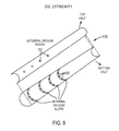
- FIG. 8 shows details of the perforated die extremity that permits oil water and vapor to be vacuumed out of the treated distiller grain
- FIGS. 9A-9B show the device that adjusts the length of pellets exiting the die extremity.
- FIG. 10 illustrates an operational flow chart of a method of producing distiller grain pellets utilizing the device in accordance with the present teachings.
- distiller grain pellet producing devices described herein enable pellet production without the addition of binders and fillers to avoid negatively affecting the nutritional value of the final product.
- Various embodiments of the distiller grain pellet producing devices produces a livestock feed material in the form of pelletized distiller dried grains having high shipping durability, high quality, and high nutritional value. The final product provides optimum nutritional value in a very compact and efficient form.
- Various embodiments extract and collect grain oils and moisture from the distiller dried grains during the production process.
- Various embodiments of the pellet producing device pass the distiller dried grain through a die that applies a cross-sectional compression, while controlling the density of the product.
- Various embodiments of the pellet producing device in various structural forms, for example, in the form of pellets, cubes, or tubs having various configurations such as round, square, rectangular or oblong.
- Various embodiments of the pellet producing device provides a high-protein and fat content product, without additives, that can be spread onto the ground as livestock feed and is capable of enduring various weather conditions. Various embodiments provide a method that does not require heating or curing of the pellets after the pellets are produced. Various embodiments of the pellet producing device take an initial by-product of an ethanol production or a corn by-product and produce a dried distiller grain product capable of being consumed by livestock.
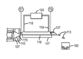
- FIG. 1A shows a schematic diagram of a distiller grain (DG) pellet production device 100 which can be used to process dried distiller grains into pelletized distiller grain product.
- the pellet production device 100 can include a loading zone, which may include a hopper 101 , a heating zone, which may include heaters 105 , a compression zone, which may include a compression enclosure 110 , and a cooling zone, which may include a heat exchanger 117 .
- the device 100 can include a loading zone for loading the distiller dried grains into the heating zone.
- Distiller dried grains supplied from hopper 101 in loose granular form can be feed into the heating zone at an inlet chute 102 of a profile screw extruder 112 shown in FIGS. 1A and 2 .
- a variable speed motor 104 connects to the screw of the extruder and drives the screw element 103 of the profile screw extruder.
- the distiller dried grains entering the profile screw extruder at inlet chute 102 can have a moisture content in the range of about 10-15% by weight.
- heat is added to the distiller dried grain by heaters 105 positioned along the wall 106 of the profile screw extruder.
- FIG. 2 shows a general shape of the profile screw 112 where the shaft diameter increases from d 1 to d 2 along the length of the screw which creates an increasing compression force on the treated material being conveyed downward due to the rotation of the screw.
- the heaters 105 can be arranged along the profile screw 112 in heating zones where the individual heaters can be equipped with independent heater controls for creating separate heating zones where selected temperatures are maintained in the treated distiller grain as it is conveyed and compressed in the profile extruder 112 .
- the type of heater devices employed for heating the treated material can include but are not limited to electric heaters, combustion gas heaters, microwave heaters, solar powered heaters or any combination of these or any other suitable heating devices.
- a series of temperature sensors may be embedded within the wall 106 of the profile screw extruder. These temperature sensors can be used to monitor the temperature of the treated material so that appropriate adjustments to the heater output, distiller died grain feeding rate, and profile screw rotation rate are regulated to maintain the treated material within a desired temperature range along the treatment zones of the profile screw extruder 112 . While five temperature sensors are shown, it should be understood that there may be more temperature sensors or less temperature sensors depending on the material treated, the length of the profile screw extruder and the desired precision of temperature monitoring within the heating and compression treatment zone.
- the temperature sensors may be connected in a computer control loop where the individual heater output regulators, a profile screw extruder motor speed regulator, and a distiller grain feed flow controller may all be individually controlled by a controller 10 to maintain preselected temperature conditions in the treated distiller grain as it travels along the profile screw extruder 112 .
- the distiller grain is forced through a first die orifice 107 located at the entrance of die 110 by the pressure applied to the treated material due to the rotation of the profile extruder 112 .
- This first die orifice 107 generally has a cross section area that is less than the cross sectional area defined by the circumference of the inside wall 108 of the outlet 111 of the profile extruder shown in FIG. 2 .
- the configuration of the die 110 performs a critical function in the process to form the treated distiller grain.
- the die 110 is configured such that the distiller grain is compressed parallel to its axis of transport and it is also compressed in a direction transverse to the direction of transport as it passes through.
- FIG. 3 A simulated free body diagram of the compressive forces on the treated material at location 114 inside the enclosure is shown in FIG. 3 where T F represents the transverse compression force and H F represents the force acting parallel to the axis of material transport.
- This transverse compression T F of the treated distiller dried grain strengthens the outer surface of the treated distiller grain which results in a more durable final product.
- the amount of transverse compression T F that is applied to the distiller dried grain in compression enclosure 110 depends on the pressure applied by the profile extruder 112 , the length of enclosure 110 and the angle of inclination A of the surface walls. These parameters can be selected to design a specific compression enclosure 110 to obtain a desired outer surface durability of the final product and the type of material that is being treated.
- the compression enclosure is shown as a die having a conical shaped configuration.
- the compression enclosure is shown as a die having a conical shaped configuration.
- the transverse compression force T F and the parallel force H F are approximately equal for most, but not all applications.
- Several sensors can be employed to assist in monitoring the condition of the distiller grain as it passes through the compression enclosure 110 .
- temperature sensor T5 the temperature of the treated distiller grain can be measured prior to entering the first die orifice 107 .
- a further distiller dried grain temperature reading can be measured between the first die orifice 107 and the second die orifice 115 by temperature sensor T7.
- Another temperature reading can be taken at temperature sensor T8 to measure the temperature of the treated distiller grain after it passes the second die orifice 115 and exits the die extremity tube 116 .
- the moisture (mainly corn oil) in the distiller grain is forced to the outside walls of the extrudate after exiting the second die orifice 115 .
- the mixture of heated liquid and vapor from the oil and water in the distiller grain migrates to and collects on the outer surfaces of the treated distiller grain to form a lubrication layer.
- the oil functions as a lubricant between outer surface of the distiller grain and the inner wall of the die extremity tube 116 and helps the distiller grain to pass through the die extremity.
- the treated distiller grain is still in a relatively modulus state when it is directed into a die extremity tube 116 .
- the compression enclosure 110 may include a plurality of die extremity tubes 116 , as shown in FIGS. 4 and 5 .
- the die extremity tubes 116 may have a cross section opening that will produce a round, square, rectangular or oblong shape to name just a few of the possible configurations.
- FIG. 4 shows a modified compression enclosure 110 a with multiple die openings 115 .
- FIG. 5 shows different die extremity tubes 116 having different diameter and shape extending from the modified compression enclosure 110 b .
- a partial listing of cooling devices and methods that may be used would include cryogenic coolers, refrigerated air heat exchangers, water chillers, cooling towers and any other known cooling device or combination of cooling devices that are capable of cooling the treated distiller grain to a stable internal temperature before it is discharges as a final product.
- Another exemplary cooling system for multiple die extremity tubes is shown in FIG. 5 .
- two different shaped die extremity tubes 116 a and 116 b are cooled in heat exchangers 117 a and 117 b .
- the control of the flow of the coolant to the heat exchangers 117 a , 117 b is regulated by control valves 125 a and 125 b .
- FIG. 6 Another exemplary embodiment of a cooling arrangement is shown in FIG. 6 .
- two vapor compression refrigeration systems are used to cool the treated distiller grain in the die extremity tubes.
- Refrigeration compressors 121 a and 121 b direct compressed refrigerant vapor to condensers 122 a and 122 b .
- the condensed refrigerant is than passed through expansion valves 123 a and 123 b where low pressure cool refrigerant is then passed into heat exchangers coils 117 a and 117 b .
- FIG. 7A shows an optional water/vapor and oil extraction and recovery system.
- the extraction system is deployed at the end of the die extremity tube 116 .
- the distiller grain exiting the die extremity tube 116 enters a perforated pipe 129 having perforations 130 that are arranged in slots around the lower portion of pipe 129 .
- Perforations 131 are provided in the upper portion of pipe 129 .
- Pipe 129 is surrounded by a tube 132 that includes a collection pipe 133 which in turn is connected to separating vessel 134 .
- FIG. 8 shows further details of the perforations 130 and 131 in pipe 129 .
- a pipe 135 is connected to the inlet of a vacuum pump 136 which discharges into pipe 162 .
- a vacuum is created in the space between the inner wall of tube 132 and the openings 130 and 131 in the perforated pipe that are exposed to the surface treated distiller dried grain inside pipe 129 .
- the vacuum acts to extract oil, water and/or vapor from the surface and the interior of the treated distiller grain through the openings 30 , 31 as the treated material passes through inside pipe 129 .
- the collected oil, water and/or vapor are then directed to the separator tank 134 by way of pipe 133 .
- the separation tank 134 directs the collected oil, water and/or vapor through a path that separates the oil from the water within the separator tank.
- the oil is then drawn out of the separation tank to be used on site or to be shipped out to be processed into other products such as diesel fuel.
- the water may be collected and used on site or it may be discharged out of pipe 147 .
- the inlets and outlets 144 and 145 are interchangeable depending on the type of coolant flow desired.
- the perforations 130 and 131 are located between the coils 44 that form the heat exchanger.
- a tube 132 encloses the heat exchanger 144 and the perforated pipe 129 .
- the perforations 130 and 131 are spaced such that they are not covered or obstructed by the heat exchanger coils 144 .
- the space between the inside wall of pipe 132 and the perforations 130 and 131 in pipe 129 are subjected to a vacuum by way of pipe 133 that is connected to separating tank 134 and vacuum pump 136 .
- FIG. 9A shows a cutting device 137 that may be used after the cooling process to cut the treated material into pellets having a desired length.
- the pellets may also be referred to as range cubes.
- the cutting device 137 includes a mounting bar 138 a lateral adjustment clamp 139 that is connected to a connecting rod 40 which is pivotally connected at pivot 143 to the pellet length adjustment member 142 .
- a locking bolt 150 screws into the top of clamp 139 to secure the lateral position of the connecting rod 140 on the support bar 138 .
- the pivot point 143 shown in FIG. 9B comprises two spaced apart members 151 and 152 that receive connecting rod 140 . Members 151 , 152 and 140 are secured in a pivoting relationship by bolt 149 and lock nut 148 .
- the pivot 143 may be in the form of a ball and socket or any other device that will permit adjustable pivotal motion between the connecting rod 140 and pellet length adjustment member 142 .
- the support bar 138 can be mounted on the end of the die extremity tube 116 or other support member. In FIGS. 1A, 1B, 7A, and 7B , this cutting device 137 is positioned above the exit point of device 100 such that it cuts the treated material into pellets, which may be collected into a container 160 . By adjusting the lateral position of the pellet length adjuster 142 along the support bar 138 , as shown by the longitudinal directional arrow in FIG.
- the cutting device 137 can be connected to a support surface of the system via support bar 138 ( FIGS. 7A, 7B, 9A, and 9B ).
- the cutting device 137 can be longitudinally movable relative to the support surface via support bar 138 , as shown by the longitudinal directional arrow in FIG. 9A , such that the cutting device 137 is adjustable between a retracted configuration and an extended configuration.
- the cutting device 137 can be configured to pivot relative to the support surface as depicted by the arcuate directional arrow in FIG. 9A .
- the cutting device 137 can be configured to include a tip portion having, for example, a slanted configuration (best shown in the slanted position in FIGS. 1A, 1B, 7A, and 7B ) configured to exert a force on the dense compact body 113 to break off the dense compact body exiting the system to the predetermined length.
- the extrudate may simply split open relieving the boiling gas of the water and corn oil mixture and damaging the integrity and size and shape and density of the extrudate.
- multiple die extremities 116 , 116 a , 116 b may be included on the same die to allow for high volume output of extrudate but still allowing a slow speed within each die extremity for longer dwell time to achieve adequate cooling.
- the examples in FIGS. 4-5 show only two to three multiple die extremities extending from a single die, but the design is not limited to this exemplary embodiment.
- the device has been designed and manufactured to include, for example, fifteen to twenty die extremities extending from a single die.
- FIG. 10 illustrates an operational flow chart of a method for producing the distiller grain pellets utilizing the device in accordance with the present teachings.
- Dried corn distiller grain with a moisture content of about 10-12% by weight is feed into hopper at block 200 .
- the dried corn distiller grain is passed into a heating zone comprising one or more heaters and a rotating screw as indicated in block 210 .
- the dried corn distiller grain is gradually heated in by electrical heaters, for example, in five heating zones where the dried corn distiller grain is heated to about 140 degrees Fahrenheit by the time it arrives at the location designated as T5. Rotation of the screw transfers the dried corn distiller grain through the heating zone while simultaneously increasing the compressive force applied to the distiller grain as indicated at block 220 .
- the distiller grain becomes modulus such that it is capable of flowing through a the restrictive die.
- the dried corn distiller grain is transferred into a compression enclosure that simultaneously applies a transverse force and a parallel force onto the distiller grain as indicated at block 230 .
- the dried corn distiller grain is pressed through the first die orifice 107 .
- pellet producing device and method of the present disclosure without departing from the scope of its teachings.
- a wide variety of different kinds of pellets, cubes or tubs can be produced from various loose granular materials using substantially the same device since virtually unlimited numbers of shapes of the compression enclosure and one or more die extremity tubes can be designed and used to meet the requirements of a particular loose granular material.
- the device may be used to compress feeding products such sorghum.
- various embodiment of the device includes a controller 10 that controls various sensors and components, such as pressure sensors, humidity sensors, temperature sensors, and drive controls, positioned in various locations throughout the device and connected in a computer control loop to set, maintain and control preselected conditions such as temperature, pressure, humidity, density, flow rate, and residence time in the treated material and/or components of the system.
- sensors and components such as pressure sensors, humidity sensors, temperature sensors, and drive controls, positioned in various locations throughout the device and connected in a computer control loop to set, maintain and control preselected conditions such as temperature, pressure, humidity, density, flow rate, and residence time in the treated material and/or components of the system.
Abstract
Description
Claims (12)
Priority Applications (6)
| Application Number | Priority Date | Filing Date | Title |
|---|---|---|---|
| US14/182,094 US9801407B2 (en) | 2011-04-15 | 2014-02-17 | Compression system for producing a high density compact product |
| US14/823,352 US9282764B1 (en) | 2011-04-15 | 2015-08-11 | Distiller grain production device |
| US14/845,107 US9481120B2 (en) | 2011-04-15 | 2015-09-03 | Distiller grain production device |
| US14/845,079 US9480281B1 (en) | 2011-04-15 | 2015-09-03 | Distiller grain production device |
| US15/339,818 US20170042212A1 (en) | 2011-04-15 | 2016-10-31 | Distiller grain production device |
| US15/947,752 US20180220694A1 (en) | 2011-04-15 | 2018-04-06 | Distiller grain production device |
Applications Claiming Priority (4)
| Application Number | Priority Date | Filing Date | Title |
|---|---|---|---|
| US201161476224P | 2011-04-15 | 2011-04-15 | |
| US13/448,358 US8287268B1 (en) | 2011-04-15 | 2012-04-16 | Distiller grain pellet production devices |
| US13/652,393 US8652555B2 (en) | 2011-04-15 | 2012-10-15 | Distiller grain pellet production methods |
| US14/182,094 US9801407B2 (en) | 2011-04-15 | 2014-02-17 | Compression system for producing a high density compact product |
Related Parent Applications (1)
| Application Number | Title | Priority Date | Filing Date |
|---|---|---|---|
| US13/652,393 Continuation US8652555B2 (en) | 2011-04-15 | 2012-10-15 | Distiller grain pellet production methods |
Related Child Applications (1)
| Application Number | Title | Priority Date | Filing Date |
|---|---|---|---|
| US14/823,352 Continuation US9282764B1 (en) | 2011-04-15 | 2015-08-11 | Distiller grain production device |
Publications (2)
| Publication Number | Publication Date |
|---|---|
| US20140161921A1 US20140161921A1 (en) | 2014-06-12 |
| US9801407B2 true US9801407B2 (en) | 2017-10-31 |
Family
ID=46981666
Family Applications (8)
| Application Number | Title | Priority Date | Filing Date |
|---|---|---|---|
| US13/448,358 Active US8287268B1 (en) | 2011-04-15 | 2012-04-16 | Distiller grain pellet production devices |
| US13/652,393 Expired - Fee Related US8652555B2 (en) | 2011-04-15 | 2012-10-15 | Distiller grain pellet production methods |
| US14/182,094 Expired - Fee Related US9801407B2 (en) | 2011-04-15 | 2014-02-17 | Compression system for producing a high density compact product |
| US14/823,352 Expired - Fee Related US9282764B1 (en) | 2011-04-15 | 2015-08-11 | Distiller grain production device |
| US14/845,107 Expired - Fee Related US9481120B2 (en) | 2011-04-15 | 2015-09-03 | Distiller grain production device |
| US14/845,079 Active US9480281B1 (en) | 2011-04-15 | 2015-09-03 | Distiller grain production device |
| US15/339,818 Abandoned US20170042212A1 (en) | 2011-04-15 | 2016-10-31 | Distiller grain production device |
| US15/947,752 Abandoned US20180220694A1 (en) | 2011-04-15 | 2018-04-06 | Distiller grain production device |
Family Applications Before (2)
| Application Number | Title | Priority Date | Filing Date |
|---|---|---|---|
| US13/448,358 Active US8287268B1 (en) | 2011-04-15 | 2012-04-16 | Distiller grain pellet production devices |
| US13/652,393 Expired - Fee Related US8652555B2 (en) | 2011-04-15 | 2012-10-15 | Distiller grain pellet production methods |
Family Applications After (5)
| Application Number | Title | Priority Date | Filing Date |
|---|---|---|---|
| US14/823,352 Expired - Fee Related US9282764B1 (en) | 2011-04-15 | 2015-08-11 | Distiller grain production device |
| US14/845,107 Expired - Fee Related US9481120B2 (en) | 2011-04-15 | 2015-09-03 | Distiller grain production device |
| US14/845,079 Active US9480281B1 (en) | 2011-04-15 | 2015-09-03 | Distiller grain production device |
| US15/339,818 Abandoned US20170042212A1 (en) | 2011-04-15 | 2016-10-31 | Distiller grain production device |
| US15/947,752 Abandoned US20180220694A1 (en) | 2011-04-15 | 2018-04-06 | Distiller grain production device |
Country Status (1)
| Country | Link |
|---|---|
| US (8) | US8287268B1 (en) |
Cited By (1)
| Publication number | Priority date | Publication date | Assignee | Title |
|---|---|---|---|---|
| US20180103655A1 (en) * | 2016-10-18 | 2018-04-19 | Ferrara Candy Company | Hard Candy with Gummy Center and Systems and Methods for Making Same |
Families Citing this family (49)
| Publication number | Priority date | Publication date | Assignee | Title |
|---|---|---|---|---|
| US9707728B2 (en) * | 2015-03-06 | 2017-07-18 | Nationwide 5, Llc | Grain dehydrating compressor for wet grain system and method |
| US9897375B2 (en) * | 2011-04-15 | 2018-02-20 | Nationwide 5, Llc | Continuous flow dryer for treating bulk material |
| US8287268B1 (en) | 2011-04-15 | 2012-10-16 | Thomas Michael R | Distiller grain pellet production devices |
| DE102012208677B4 (en) * | 2012-05-23 | 2018-08-02 | Battenfeld-Cincinnati Germany Gmbh | Method and device for tempering plastic plastic material |
| US10863765B2 (en) * | 2012-10-24 | 2020-12-15 | Nationwide 5, Llc | High-fat and high-protein animal feed supplement and process of manufacture |
| CN105008490B (en) * | 2013-01-25 | 2017-03-29 | 卡拉厄里斯能源与环境有限公司 | Turbulent flow Vacuum Heat separation method and system |
| US9968114B1 (en) | 2013-10-18 | 2018-05-15 | Purina Animal Nutrition Llc | System and method for producing pelleted animal feed blocks |
| US10667545B2 (en) | 2014-05-15 | 2020-06-02 | Purina Animal Nutrition Llc | Methods of feeding high fat poured feed blocks |
| US9936720B2 (en) | 2014-05-15 | 2018-04-10 | Purina Animal Nutrition Llc | High fat poured feed block |
| US20160066600A1 (en) * | 2014-09-08 | 2016-03-10 | The United States Of America, As Represented By The Secretary Of Agriculture | Method and System for Producing Aquaculture Feed |
| JP6463508B2 (en) * | 2015-01-16 | 2019-02-06 | ココテッラ カンパニーCocoTerra Company | Chocolate processing system and method |
| US9616632B2 (en) * | 2015-03-06 | 2017-04-11 | Nationwide 5, Llc | Wet grain drying system and method |
| CN105076291A (en) * | 2015-07-12 | 2015-11-25 | 湖南飘香食品有限公司 | Screw-type cooling and oil draining machine |
| BR112018008829A2 (en) * | 2015-12-02 | 2018-11-06 | Agrisoma Biosciences Inc. | Method to Remove Glycosinolates from Oilseed Flours |
| BR112018013547B1 (en) * | 2016-01-18 | 2022-11-01 | Kellogg Company | APPARATUS AND METHOD FOR PRODUCING CEREAL IN THE FORM OF FLAKES WITHOUT THE USE OF A FLAKE FORMING MILL |
| US9750268B1 (en) * | 2016-04-19 | 2017-09-05 | Nationwide 5, Llc | Grain bulk densifying die apparatus and method |
| EP3445481B1 (en) * | 2016-04-22 | 2021-11-03 | Steerlife India Private Limited | Fractional lobe processor, and related process for the wet granulation of powdery material |
| US10739426B2 (en) * | 2016-06-28 | 2020-08-11 | Koninklijke Philips N.V. | Magnetic resonance imaging with improved thermal performance |
| CN106799824A (en) * | 2017-02-15 | 2017-06-06 | 黄浩华 | Expansion-exsiccation machine |
| US20190024974A1 (en) * | 2017-07-20 | 2019-01-24 | DryAir LLC | Grain drying auger and drum with air holes |
| CN107536092A (en) * | 2017-08-15 | 2018-01-05 | 山东誉亚大豆机械制造有限公司 | Plain meat forming machine |
| CN107741135B (en) * | 2017-10-25 | 2019-11-01 | 宣城市水阳三宝食品有限公司 | A kind of eight-angle drier of cooking stove baking |
| CN107906853A (en) * | 2017-11-09 | 2018-04-13 | 湖州览春酒业有限公司 | Wine brewing vinasse press filtration drying mechanism |
| RU186434U1 (en) * | 2018-05-29 | 2019-01-21 | Федеральное государственное бюджетное образовательное учреждение высшего образования "Ульяновский государственный аграрный университет имени П.А. Столыпина" | DEVICE FOR GRAIN DRYING |
| RU186440U1 (en) * | 2018-05-29 | 2019-01-21 | Федеральное государственное бюджетное образовательное учреждение высшего образования "Ульяновский государственный аграрный университет имени П.А. Столыпина" | DEVICE FOR GRAIN DRYING |
| CN111156814B (en) * | 2018-11-07 | 2024-03-29 | 中石化石油工程技术服务股份有限公司 | Internal circulation rock debris material dehumidification device |
| KR20210099646A (en) * | 2018-12-14 | 2021-08-12 | 차이나 토바코 후난 인더스트리얼 코포레이션 리미티드 | Molding device, cigarette filter rod and manufacturing method thereof |
| US11470853B2 (en) | 2019-03-15 | 2022-10-18 | CocoTerra Company | Interface and application for designing a chocolate-making experience |
| RU192090U1 (en) * | 2019-07-05 | 2019-09-03 | Федеральное государственное бюджетное образовательное учреждение высшего образования "Белгородский государственный аграрный университет имени В.Я. Горина" | Granulating auger press for feed mixtures with grass meal |
| CN110403217A (en) * | 2019-08-30 | 2019-11-05 | 淮北市乾乾生物科技有限公司 | A kind of livestock feed processing extruding apparatus and its application method |
| CN110558200A (en) * | 2019-10-17 | 2019-12-13 | 安徽省金裕皖酒业有限公司 | vinasse matrix for non-edible fungus cultivation and preparation method and application thereof |
| CN110715513B (en) * | 2019-10-29 | 2020-09-04 | 福州众点网络技术开发有限公司 | Extrusion type dehydration equipment for activated carbon raw materials |
| CN110694555A (en) * | 2019-11-04 | 2020-01-17 | 蒋加顺 | High-efficient fodder pelletization device based on carousel cutting |
| CN111067120B (en) * | 2020-01-17 | 2021-10-15 | 淮北瑞农饲料有限公司 | Pellet feed former |
| CN111334870B (en) * | 2020-03-24 | 2022-04-12 | 福建唐源合纤科技有限公司 | A novel screw extruder feeding structure for production of polyamide fibre 6 polymeric fiber |
| WO2021198501A1 (en) * | 2020-04-01 | 2021-10-07 | Mars, Incorporated | Process for producing a meat analogue and apparatus therefor |
| CN111588056B (en) * | 2020-06-04 | 2021-05-18 | 四川利达华锐机械有限公司 | Stable fodder granulation machine subassembly of even ejection of compact of granule |
| CN112146354A (en) * | 2020-09-17 | 2020-12-29 | 庞玉琼 | Lees drying device is used in white spirit production |
| CN112385871B (en) * | 2020-11-13 | 2021-08-17 | 沈阳美佳营养科技有限公司 | Feed granulator |
| CN112985041A (en) * | 2021-03-08 | 2021-06-18 | 深圳市迅捷兴科技股份有限公司 | Circuit board moves back membrane section waste film sediment dewatering device |
| RU2761465C1 (en) * | 2021-03-11 | 2021-12-08 | Федеральное государственное бюджетное образовательное учреждение высшего образования "Кубанский государственный аграрный университет имени И.Т. Трубилина" | Press-granulator for high-protein feed |
| CN114098129A (en) * | 2021-12-01 | 2022-03-01 | 哈尔滨天通生物工程技术有限公司 | Dry-method puffing process and dry-method puffing machine |
| CH719199B1 (en) * | 2021-12-03 | 2023-11-15 | Circular Food Solutions Ag | Textured, high-moisture plant protein from brewer's spent grains. |
| EP4190164A1 (en) * | 2021-12-03 | 2023-06-07 | Circular Food Solutions AG | Low moisture texturised plant protein from brewer's spent grain |
| CH719198B1 (en) * | 2021-12-03 | 2023-11-15 | Circular Food Solutions Ag | Textured, low-moisture plant protein made from spent grains. |
| EP4190166A1 (en) * | 2021-12-03 | 2023-06-07 | Circular Food Solutions AG | High moisture texturised plant protein from brewer's spent grain |
| CN114274486B (en) * | 2021-12-21 | 2023-10-13 | 安庆市悦发管业有限公司 | Extrusion die for double-layer multipoint support HDPE winding pipe |
| CN114603818B (en) * | 2022-03-24 | 2023-08-18 | 江西理工大学 | Double-screw extruder for biodegradable materials |
| CN115682650A (en) * | 2022-11-02 | 2023-02-03 | 西安泰金新能科技股份有限公司 | Lightweight rubber roll capable of monitoring pressing force |
Citations (33)
| Publication number | Priority date | Publication date | Assignee | Title |
|---|---|---|---|---|
| US2373167A (en) * | 1943-03-31 | 1945-04-10 | Western Electric Co | Extrusion apparatus |
| US3357049A (en) * | 1964-12-18 | 1967-12-12 | Spindler Wolfgang | Extruder control system |
| US3499952A (en) * | 1967-01-19 | 1970-03-10 | Phillips Petroleum Co | Pressure regulation in visbreaking extruder |
| US3868469A (en) | 1972-05-16 | 1975-02-25 | Manuel L Chalin | Method of dutching cocoa |
| US3904769A (en) * | 1973-07-05 | 1975-09-09 | Griffith Laboratories | Structured products having controlled gas-generated cells therein and methods of making them |
| US3970761A (en) | 1975-05-27 | 1976-07-20 | Wenger Manufacturing | Method of preparing dense, uniformly layered vegetable protein meat analogue |
| US4042715A (en) | 1975-05-27 | 1977-08-16 | Wenger Manufacturing | Dense, uniformly layered vegetable protein meat analogue |
| US4185123A (en) | 1977-07-15 | 1980-01-22 | Wenger Manufacturing | High-output method for producing dense, uniformly layered meat analogue product |
| US4260351A (en) * | 1975-11-04 | 1981-04-07 | Hitachi Cables, Ltd. | Apparatus for producing foamed plastic insulated wires |
| US4372734A (en) | 1980-02-06 | 1983-02-08 | General Foods Inc. | Apparatus for mixing and extruding simulated meat mix for pet food |
| US4423082A (en) | 1981-11-23 | 1983-12-27 | Kraft, Inc. | Method for manufacturing quick cooking pasta products |
| US4882105A (en) | 1987-11-09 | 1989-11-21 | Beta Raven Inc. | Method of automatically controlling an extruder |
| US5242292A (en) | 1991-09-30 | 1993-09-07 | Wenger Manufacturing, Inc. | Extruder apparatus for producing sterile pelleted feed product |
| US5413475A (en) | 1992-02-27 | 1995-05-09 | Mitsubishi Jukogyo Kabushiki Kaisha | Serial two-stage extruder |
| US5525050A (en) | 1992-08-11 | 1996-06-11 | Nissei Plastic Industrial Co., Ltd. | Temperature control unit for injection molding machines |
| US5558886A (en) | 1993-10-21 | 1996-09-24 | Centro De Investigacion Y De Estudios Avanzados Del I.P.N. | Extrusion apparatus for the preparation of instant fresh corn dough or masa |
| US5643618A (en) | 1994-05-11 | 1997-07-01 | General Mills, Inc. | Apparatus for making multiple, complexly patterned extrudates |
| US5776534A (en) | 1996-04-03 | 1998-07-07 | General Mills, Inc. | Food apparatus for forming multiple colored extrudates and method of preparation |
| US5919509A (en) | 1997-05-01 | 1999-07-06 | General Mills, Inc. | Method and apparatus for producing multiple food extrudates |
| US6277425B1 (en) | 1998-12-28 | 2001-08-21 | Good Mark Foods, Inc. | Method for producing an extruded cooked food product |
| US6403138B1 (en) | 2000-07-28 | 2002-06-11 | Kraft Foods Holdings, Inc. | Method for reforming dairy products |
| US20040032040A1 (en) * | 2002-08-13 | 2004-02-19 | Harris Holton E. | Plastics extruder dimension and viscosity control system and method |
| US20050230872A1 (en) * | 2004-03-26 | 2005-10-20 | Scobee Robert E | Pellet mill and method of making peanut hull granules |
| US20060138690A1 (en) * | 2004-06-25 | 2006-06-29 | Technoplast Kunststofftechnik Gmbh & Co. Kg | Method for producing profiles made of thermoplastic material |
| US7097873B2 (en) | 2000-01-18 | 2006-08-29 | Clextral | Method and installation for continuously preparing caseinate |
| US7347965B2 (en) | 2005-09-29 | 2008-03-25 | Uniloy Milacron Usa, Inc. | Apparatus and method for injection molding |
| US20080290548A1 (en) | 2007-05-22 | 2008-11-27 | Scott Landers | Pellet mill die and pelletizing process |
| US20090238920A1 (en) | 2008-03-21 | 2009-09-24 | Lewis Ted C | Process for making high grade protein product |
| US20090304835A1 (en) | 2006-01-25 | 2009-12-10 | Absorbent Technologies, Inc. | Methods For Producing Superabsorbent Polymers For Use In Agricultural Applications |
| US20100074981A1 (en) | 2001-10-29 | 2010-03-25 | Frito-Lay Of North America, Inc. | Apparatus and Method for Imprinting Lines on Direct-Expanded Food Products Having Complex Shapes With Improved Dimensional Quality |
| US7695747B2 (en) | 2007-09-17 | 2010-04-13 | Russell Meier | Method of producing dried distillers grain agglomerated particles |
| US8067047B2 (en) | 2006-06-27 | 2011-11-29 | James Fajt | Method and devices for forming articles |
| US8118582B1 (en) | 2008-04-03 | 2012-02-21 | Purdue Research Foundation | Method and apparatus for producing biobased carriers from byproducts of biomass processing |
Family Cites Families (19)
| Publication number | Priority date | Publication date | Assignee | Title |
|---|---|---|---|---|
| US3032822A (en) * | 1959-05-05 | 1962-05-08 | Union Carbide Corp | Extrusion control |
| US3085289A (en) * | 1961-04-03 | 1963-04-16 | Jurian W Van Riper | Plastic material extrusion head |
| US3924997A (en) * | 1972-08-21 | 1975-12-09 | Phillips Petroleum Co | Apparatus for drying polymeric material |
| US4173445A (en) * | 1978-07-17 | 1979-11-06 | Monsanto Company | Plastics extrusion apparatus |
| US4290989A (en) * | 1979-12-10 | 1981-09-22 | Frito-Lay, Inc. | Method and apparatus for extruding a plurality of ribbons |
| US4632795A (en) * | 1982-11-26 | 1986-12-30 | Wenger Manufacturing, Inc. | Method and apparatus for extrusion processing of cellulose bearing materials |
| US4883421A (en) * | 1987-03-10 | 1989-11-28 | Nabisco Brands, Inc. | Directional flow bar extruder |
| US4979434A (en) * | 1989-06-07 | 1990-12-25 | Nabisco Brands, Inc. | Extruder apparatus for producing an at least partially baked product having a cookie-like crumb structure |
| US5077074A (en) * | 1989-06-07 | 1991-12-31 | Nabisco Brands, Inc. | Preparation of cookie products involving extrusion heating and wire cutting |
| JP4670174B2 (en) * | 2000-06-30 | 2011-04-13 | 株式会社デンソー | Ceramic sheet forming method and forming apparatus |
| AT410195B (en) * | 2001-05-09 | 2003-02-25 | Technoplast Kunststofftechnik | METHOD AND DEVICE FOR ADAPTING AN EXTRUSION TOOL TO AN EXTRUDER |
| US6620448B2 (en) * | 2001-10-29 | 2003-09-16 | Recot, Inc. | Extruder die with additive reservoir |
| US6783787B2 (en) * | 2002-03-28 | 2004-08-31 | Frito-Lay North America, Inc. | Apparatus and method for improving the dimensional quality of direct-expanded food products having complex shapes |
| US6854970B2 (en) * | 2001-10-29 | 2005-02-15 | Frito-Lay North America, Inc. | Extruder die injection nozzle |
| ES2339000T3 (en) * | 2002-01-14 | 2010-05-14 | Buhler Ag | MACHINE TO PROCESS FLUID / PASTABLE MASSES THROUGH A SECTION THAT CAN BE VIBRATED IN THE TRANSPORT DIRECTION. |
| US7318720B2 (en) * | 2003-08-07 | 2008-01-15 | Arunas Antanas Pabedinskas | Die assembly and production process for profile extrusion |
| US8926308B2 (en) * | 2010-04-21 | 2015-01-06 | Intercontinental Great Brands Llc | Dough extruders and methods |
| US8287268B1 (en) | 2011-04-15 | 2012-10-16 | Thomas Michael R | Distiller grain pellet production devices |
| US8714952B2 (en) * | 2011-06-13 | 2014-05-06 | Floracraft Corp. | System and method for manufacturing cylindrical foam articles |
-
2012
- 2012-04-16 US US13/448,358 patent/US8287268B1/en active Active
- 2012-10-15 US US13/652,393 patent/US8652555B2/en not_active Expired - Fee Related
-
2014
- 2014-02-17 US US14/182,094 patent/US9801407B2/en not_active Expired - Fee Related
-
2015
- 2015-08-11 US US14/823,352 patent/US9282764B1/en not_active Expired - Fee Related
- 2015-09-03 US US14/845,107 patent/US9481120B2/en not_active Expired - Fee Related
- 2015-09-03 US US14/845,079 patent/US9480281B1/en active Active
-
2016
- 2016-10-31 US US15/339,818 patent/US20170042212A1/en not_active Abandoned
-
2018
- 2018-04-06 US US15/947,752 patent/US20180220694A1/en not_active Abandoned
Patent Citations (33)
| Publication number | Priority date | Publication date | Assignee | Title |
|---|---|---|---|---|
| US2373167A (en) * | 1943-03-31 | 1945-04-10 | Western Electric Co | Extrusion apparatus |
| US3357049A (en) * | 1964-12-18 | 1967-12-12 | Spindler Wolfgang | Extruder control system |
| US3499952A (en) * | 1967-01-19 | 1970-03-10 | Phillips Petroleum Co | Pressure regulation in visbreaking extruder |
| US3868469A (en) | 1972-05-16 | 1975-02-25 | Manuel L Chalin | Method of dutching cocoa |
| US3904769A (en) * | 1973-07-05 | 1975-09-09 | Griffith Laboratories | Structured products having controlled gas-generated cells therein and methods of making them |
| US3970761A (en) | 1975-05-27 | 1976-07-20 | Wenger Manufacturing | Method of preparing dense, uniformly layered vegetable protein meat analogue |
| US4042715A (en) | 1975-05-27 | 1977-08-16 | Wenger Manufacturing | Dense, uniformly layered vegetable protein meat analogue |
| US4260351A (en) * | 1975-11-04 | 1981-04-07 | Hitachi Cables, Ltd. | Apparatus for producing foamed plastic insulated wires |
| US4185123A (en) | 1977-07-15 | 1980-01-22 | Wenger Manufacturing | High-output method for producing dense, uniformly layered meat analogue product |
| US4372734A (en) | 1980-02-06 | 1983-02-08 | General Foods Inc. | Apparatus for mixing and extruding simulated meat mix for pet food |
| US4423082A (en) | 1981-11-23 | 1983-12-27 | Kraft, Inc. | Method for manufacturing quick cooking pasta products |
| US4882105A (en) | 1987-11-09 | 1989-11-21 | Beta Raven Inc. | Method of automatically controlling an extruder |
| US5242292A (en) | 1991-09-30 | 1993-09-07 | Wenger Manufacturing, Inc. | Extruder apparatus for producing sterile pelleted feed product |
| US5413475A (en) | 1992-02-27 | 1995-05-09 | Mitsubishi Jukogyo Kabushiki Kaisha | Serial two-stage extruder |
| US5525050A (en) | 1992-08-11 | 1996-06-11 | Nissei Plastic Industrial Co., Ltd. | Temperature control unit for injection molding machines |
| US5558886A (en) | 1993-10-21 | 1996-09-24 | Centro De Investigacion Y De Estudios Avanzados Del I.P.N. | Extrusion apparatus for the preparation of instant fresh corn dough or masa |
| US5643618A (en) | 1994-05-11 | 1997-07-01 | General Mills, Inc. | Apparatus for making multiple, complexly patterned extrudates |
| US5776534A (en) | 1996-04-03 | 1998-07-07 | General Mills, Inc. | Food apparatus for forming multiple colored extrudates and method of preparation |
| US5919509A (en) | 1997-05-01 | 1999-07-06 | General Mills, Inc. | Method and apparatus for producing multiple food extrudates |
| US6277425B1 (en) | 1998-12-28 | 2001-08-21 | Good Mark Foods, Inc. | Method for producing an extruded cooked food product |
| US7097873B2 (en) | 2000-01-18 | 2006-08-29 | Clextral | Method and installation for continuously preparing caseinate |
| US6403138B1 (en) | 2000-07-28 | 2002-06-11 | Kraft Foods Holdings, Inc. | Method for reforming dairy products |
| US20100074981A1 (en) | 2001-10-29 | 2010-03-25 | Frito-Lay Of North America, Inc. | Apparatus and Method for Imprinting Lines on Direct-Expanded Food Products Having Complex Shapes With Improved Dimensional Quality |
| US20040032040A1 (en) * | 2002-08-13 | 2004-02-19 | Harris Holton E. | Plastics extruder dimension and viscosity control system and method |
| US20050230872A1 (en) * | 2004-03-26 | 2005-10-20 | Scobee Robert E | Pellet mill and method of making peanut hull granules |
| US20060138690A1 (en) * | 2004-06-25 | 2006-06-29 | Technoplast Kunststofftechnik Gmbh & Co. Kg | Method for producing profiles made of thermoplastic material |
| US7347965B2 (en) | 2005-09-29 | 2008-03-25 | Uniloy Milacron Usa, Inc. | Apparatus and method for injection molding |
| US20090304835A1 (en) | 2006-01-25 | 2009-12-10 | Absorbent Technologies, Inc. | Methods For Producing Superabsorbent Polymers For Use In Agricultural Applications |
| US8067047B2 (en) | 2006-06-27 | 2011-11-29 | James Fajt | Method and devices for forming articles |
| US20080290548A1 (en) | 2007-05-22 | 2008-11-27 | Scott Landers | Pellet mill die and pelletizing process |
| US7695747B2 (en) | 2007-09-17 | 2010-04-13 | Russell Meier | Method of producing dried distillers grain agglomerated particles |
| US20090238920A1 (en) | 2008-03-21 | 2009-09-24 | Lewis Ted C | Process for making high grade protein product |
| US8118582B1 (en) | 2008-04-03 | 2012-02-21 | Purdue Research Foundation | Method and apparatus for producing biobased carriers from byproducts of biomass processing |
Cited By (1)
| Publication number | Priority date | Publication date | Assignee | Title |
|---|---|---|---|---|
| US20180103655A1 (en) * | 2016-10-18 | 2018-04-19 | Ferrara Candy Company | Hard Candy with Gummy Center and Systems and Methods for Making Same |
Also Published As
| Publication number | Publication date |
|---|---|
| US9282764B1 (en) | 2016-03-15 |
| US9480281B1 (en) | 2016-11-01 |
| US20130040023A1 (en) | 2013-02-14 |
| US20170042212A1 (en) | 2017-02-16 |
| US20140161921A1 (en) | 2014-06-12 |
| US20120260808A1 (en) | 2012-10-18 |
| US9481120B2 (en) | 2016-11-01 |
| US8652555B2 (en) | 2014-02-18 |
| US8287268B1 (en) | 2012-10-16 |
| US20160249673A1 (en) | 2016-09-01 |
| US20180220694A1 (en) | 2018-08-09 |
Similar Documents
| Publication | Publication Date | Title |
|---|---|---|
| US9481120B2 (en) | Distiller grain production device | |
| US20180172348A1 (en) | Continuous flow dryer for treating bulk material | |
| US20210145040A1 (en) | High-Fat and High-Protein Animal Feed Supplement and Process of Manufacture | |
| US5596815A (en) | Material drying process | |
| DE69133520T2 (en) | Enthalpy control for a CO2 refrigeration system | |
| CA2944385C (en) | A method and apparatus for pressing oilseed to extract oil therefrom | |
| EP1022531B1 (en) | Process for heating bulk materials, particularly plastic granules | |
| EP2522935A2 (en) | Device for pelletising or granulating a fluid or paste material | |
| US10960632B2 (en) | Grain dehydrating compressor for wet grain system and method | |
| US20170208837A1 (en) | Wet Grain Drying System and Method | |
| US20150245652A1 (en) | System for Processing Primary Food Product Waste Into Secondary Food Product | |
| US20080178488A1 (en) | Portable counter flow drying and highly efficient grain drier with integrated heat recovery | |
| RU2493750C1 (en) | Granulated feed-stuffs production method | |
| US5928678A (en) | Mash feed conditioning apparatus | |
| CN117545537A (en) | Method and device for pressing liquid extracts from a material to be pressed | |
| DE102021005340A1 (en) | Device and method for the production of cooled fresh concrete | |
| KR101424168B1 (en) | Apparatus and operation method for pressure control of continuous dehydrating extruder | |
| WO1999060317A1 (en) | Method and plant for drying of cut/pelletized material, in particular animal and/or vegetable feed-stuff, nutrient etc. | |
| WO2002024000A1 (en) | Method and plant for producing feed pellets | |
| RU2730621C1 (en) | Fodders production method |
Legal Events
| Date | Code | Title | Description |
|---|---|---|---|
| AS | Assignment |
Owner name: INTEGRATED RESOURCES, LLC, OKLAHOMA Free format text: ASSIGNMENT OF ASSIGNORS INTEREST;ASSIGNOR:THOMAS, MICHAEL R.;REEL/FRAME:034753/0787 Effective date: 20141120 |
|
| AS | Assignment |
Owner name: V-3 NUTRITION, LLC, NEBRASKA Free format text: ASSIGNMENT OF ASSIGNORS INTEREST;ASSIGNOR:MIDWEST COMMUNITY DEVELOPMENT FUND IV, LLC;REEL/FRAME:034841/0588 Effective date: 20150115 Owner name: MIDWEST COMMUNITY DEVELOPMENT FUND IV, LLC, MISSOU Free format text: SECURITY AGREEMENT;ASSIGNORS:JOHNSON, RAYMOND TAYLOR, JR.;WESTERN, SAMANTHA RAE;THOMAS, MICHAEL RAY;REEL/FRAME:034841/0286 Effective date: 20131224 Owner name: MIDWEST COMMUNITY DEVELOPMENT FUND IV, LLC, MISSOU Free format text: ASSIGNMENT OF ASSIGNORS INTEREST;ASSIGNORS:JOHNSON, RAYMOND TAYLOR, JR;WESTERN, SAMANTHA RAE;THOMAS, MICHAEL RAY;REEL/FRAME:034841/0550 Effective date: 20131224 |
|
| AS | Assignment |
Owner name: MIDWEST COMMUNITY DEVELOPMENT FUND IV, LLC, MISSOU Free format text: CORRECTIVE ASSIGNMENT TO CORRECT THE INCORRECT PATENT NO. 8.652,855 PREVIOUSLY RECORDED AT REEL: 034841 FRAME: 0550. ASSIGNOR(S) HEREBY CONFIRMS THE ASSIGNMENT;ASSIGNORS:JOHNSON, RAYMOND TAYLOR, JR.;WESTERN, SAMANTHA RAE;THOMAS, MICHAEL RAY;REEL/FRAME:035001/0232 Effective date: 20131224 |
|
| AS | Assignment |
Owner name: WESTERN, SAMANTHA R., MARYLAND Free format text: ASSIGNMENT OF ASSIGNORS INTEREST;ASSIGNOR:THOMAS, MICHAEL R.;REEL/FRAME:034963/0843 Effective date: 20110415 Owner name: JOHNSON, RAYMOND T., MARYLAND Free format text: ASSIGNMENT OF ASSIGNORS INTEREST;ASSIGNORS:THOMAS, MICHAEL R.;WESTERN, SAMANTHA R.;REEL/FRAME:034963/0839 Effective date: 20130303 Owner name: RAYEMAN ELEMENTS, INC., NEBRASKA Free format text: LICENSE AGREEMENT;ASSIGNORS:THOMAS, MICHAEL R.;WESTERN, SAMANTHA R.;REEL/FRAME:034994/0720 Effective date: 20110415 Owner name: RAYEMAN ELEMENTS, INC., NEBRASKA Free format text: LICENSE AGREEMENT;ASSIGNOR:JOHNSON, RAY;REEL/FRAME:034994/0748 Effective date: 20130420 |
|
| AS | Assignment |
Owner name: NATIONWIDE 5, LLC, NEBRASKA Free format text: ASSIGNMENT OF ASSIGNORS INTEREST;ASSIGNOR:THOMAS, MICHAEL R.;REEL/FRAME:037875/0349 Effective date: 20160130 Owner name: THOMAS, MICHAEL R., MISSOURI Free format text: ASSIGNMENT OF ASSIGNORS INTEREST;ASSIGNOR:V-3 NUTRITION, LLC;REEL/FRAME:037875/0329 Effective date: 20160129 |
|
| AS | Assignment |
Owner name: THOMAS, MICHAEL R., MISSOURI Free format text: ASSIGNMENT OF ASSIGNORS INTEREST;ASSIGNOR:INTEGRATED RESOURCES, LLC;REEL/FRAME:040595/0011 Effective date: 20151028 |
|
| STCF | Information on status: patent grant |
Free format text: PATENTED CASE |
|
| FEPP | Fee payment procedure |
Free format text: MAINTENANCE FEE REMINDER MAILED (ORIGINAL EVENT CODE: REM.); ENTITY STATUS OF PATENT OWNER: SMALL ENTITY |
|
| LAPS | Lapse for failure to pay maintenance fees |
Free format text: PATENT EXPIRED FOR FAILURE TO PAY MAINTENANCE FEES (ORIGINAL EVENT CODE: EXP.); ENTITY STATUS OF PATENT OWNER: SMALL ENTITY |
|
| STCH | Information on status: patent discontinuation |
Free format text: PATENT EXPIRED DUE TO NONPAYMENT OF MAINTENANCE FEES UNDER 37 CFR 1.362 |
|
| FP | Lapsed due to failure to pay maintenance fee |
Effective date: 20211031 |