US9801290B2 - Foldable display - Google Patents
Foldable display Download PDFInfo
- Publication number
- US9801290B2 US9801290B2 US14/792,310 US201514792310A US9801290B2 US 9801290 B2 US9801290 B2 US 9801290B2 US 201514792310 A US201514792310 A US 201514792310A US 9801290 B2 US9801290 B2 US 9801290B2
- Authority
- US
- United States
- Prior art keywords
- axle
- guide
- engaged
- guide line
- sidewall
- Prior art date
- Legal status (The legal status is an assumption and is not a legal conclusion. Google has not performed a legal analysis and makes no representation as to the accuracy of the status listed.)
- Active, expires
Links
Images


Classifications
-
- G—PHYSICS
- G09—EDUCATION; CRYPTOGRAPHY; DISPLAY; ADVERTISING; SEALS
- G09F—DISPLAYING; ADVERTISING; SIGNS; LABELS OR NAME-PLATES; SEALS
- G09F9/00—Indicating arrangements for variable information in which the information is built-up on a support by selection or combination of individual elements
-
- H—ELECTRICITY
- H05—ELECTRIC TECHNIQUES NOT OTHERWISE PROVIDED FOR
- H05K—PRINTED CIRCUITS; CASINGS OR CONSTRUCTIONAL DETAILS OF ELECTRIC APPARATUS; MANUFACTURE OF ASSEMBLAGES OF ELECTRICAL COMPONENTS
- H05K5/00—Casings, cabinets or drawers for electric apparatus
- H05K5/0017—Casings, cabinets or drawers for electric apparatus with operator interface units
-
- G—PHYSICS
- G06—COMPUTING; CALCULATING OR COUNTING
- G06F—ELECTRIC DIGITAL DATA PROCESSING
- G06F1/00—Details not covered by groups G06F3/00 - G06F13/00 and G06F21/00
- G06F1/16—Constructional details or arrangements
- G06F1/1613—Constructional details or arrangements for portable computers
- G06F1/1633—Constructional details or arrangements of portable computers not specific to the type of enclosures covered by groups G06F1/1615 - G06F1/1626
- G06F1/1637—Details related to the display arrangement, including those related to the mounting of the display in the housing
- G06F1/1652—Details related to the display arrangement, including those related to the mounting of the display in the housing the display being flexible, e.g. mimicking a sheet of paper, or rollable
-
- G—PHYSICS
- G09—EDUCATION; CRYPTOGRAPHY; DISPLAY; ADVERTISING; SEALS
- G09F—DISPLAYING; ADVERTISING; SIGNS; LABELS OR NAME-PLATES; SEALS
- G09F9/00—Indicating arrangements for variable information in which the information is built-up on a support by selection or combination of individual elements
- G09F9/30—Indicating arrangements for variable information in which the information is built-up on a support by selection or combination of individual elements in which the desired character or characters are formed by combining individual elements
- G09F9/301—Indicating arrangements for variable information in which the information is built-up on a support by selection or combination of individual elements in which the desired character or characters are formed by combining individual elements flexible foldable or roll-able electronic displays, e.g. thin LCD, OLED
-
- H—ELECTRICITY
- H05—ELECTRIC TECHNIQUES NOT OTHERWISE PROVIDED FOR
- H05K—PRINTED CIRCUITS; CASINGS OR CONSTRUCTIONAL DETAILS OF ELECTRIC APPARATUS; MANUFACTURE OF ASSEMBLAGES OF ELECTRICAL COMPONENTS
- H05K5/00—Casings, cabinets or drawers for electric apparatus
- H05K5/02—Details
- H05K5/0217—Mechanical details of casings
- H05K5/0226—Hinges
Definitions
- the present disclosure generally relates to a foldable display.
- Rollable or foldable displays include a flexible display module.
- Flexible display modules which are bendable or foldable, have been undergoing active research and development.
- Flexible display modules include a flexible display panel and various supportive functional components.
- Such flexible display panels include a base substrate, various functional layers formed over the base substrate and pixels formed over the base substrate.
- One inventive aspect is a foldable display including a hinge member.
- Another aspect is a foldable display that can reduce deformation thereof.
- a foldable display including a housing and a flexible display module.
- the housing includes a first supporting member, a second supporting member arranged to be spaced apart from the first supporting member, and a hinge member connecting the first and second supporting members.
- the flexible display module is connected to the first and second supporting members.
- the hinge member includes a first body and a second body.
- the first body includes a rotation portion, a first axle engaged with one surface of the rotation portion, and a second axle engaged with the other surface of the rotation portion.
- the second body includes a connection portion including a first guide line facing the one surface of the rotation portion of the first body and engaged with the first axle and a second guide line facing the other surface of the rotation portion of the first body, engaged with the second axle, and having a curved line shape.
- the second body further includes a fixing portion connected to the connection portion of the second body and connected to the first supporting member.
- connection portion of the second body includes a first sidewall in which the first guide line is defined and a second sidewall in which the second guide line is defined.
- the second sidewall is spaced apart from the first sidewall to face the first sidewall.
- the first guide line is a first slit formed through the first sidewall and the second guide line is a second slit formed through the second sidewall.
- the first body further includes a fixing portion connected to the rotation portion of the first body, and the fixing portion of the first body is connected to the second supporting member.
- the hinge member further includes a third body.
- the third body includes a rotation portion, a third axle engaged with one surface of the rotation portion, and a fourth axle engaged with the other surface of the rotation portion.
- the first body further includes a connection portion including a third guide line facing the one surface of the rotation portion of the third body and engaged with the third axle and a fourth guide line facing the other surface of the rotation portion of the third body and engaged with the fourth axle.
- connection portion of the first body includes a third sidewall in which the third guide line is defined and a fourth sidewall in which the fourth guide line is defined.
- the fourth sidewall is spaced apart from the third sidewall to face the third sidewall.
- the third guide line is a third slit formed through the third sidewall and the fourth guide line is a fourth slit formed through the fourth sidewall.
- the third body further includes a fixing portion connected to the rotation portion of the third body, and the fixing portion of the third body is connected to the second supporting member.
- the hinge member can include a first body, a second body, and a third body.
- the first body includes a first axle engaged with one surface of the rotation portion, a second axle engaged with the other surface of the rotation portion, a third axle engaged with the one surface of the rotation portion and spaced apart from the first axle, and a fourth axle engaged with the other surface of the rotation portion and spaced apart from the second axle.
- the second body includes a connection portion including a first guide line facing the one surface of the rotation portion and engaged with the first axle and a second guide line facing the other surface of the rotation portion and engaged with the second axle.
- the third body includes a connection portion including a third guide line facing the one surface of the rotation portion and engaged with the third axle and a fourth guide line facing the other surface of the rotation portion and engaged with the fourth axle.
- One guide line of the first and second guide lines has a curved line shape and one guide line of the third and fourth guide lines has the curved line shape.
- connection portion of the second body includes a first sidewall in which the first guide line is defined and a second sidewall in which the second guide line is defined.
- connection portion of the third body includes a third sidewall in which the third guide line is defined and a fourth sidewall in which the fourth guide line is defined.
- the second body further includes a first fixing portion connected to the first and second sidewalls and connected to the first supporting member.
- the third body further includes a second fixing portion connected to the third and fourth sidewalls and connected to the second supporting member.
- the guide line having the curved line shape of the first and second guide lines and the guide line having the curved line shape of the third and fourth guide lines have a mirror-inverted shape when viewed in the first, second, third, and fourth sidewalls.
- Each of the first, second, third, and fourth guide lines is a slit formed through a corresponding sidewall among the first, second, third, and fourth sidewalls.
- the hinge member can include a first body, a second body, and a third body.
- the first body includes a bottom portion provided with a rotation axle, a rotation arm engaged with the rotation axle, a first connection portion comprising a first guide line having a curved line shape and a first guide slit and being formed on the bottom portion, and a second connection portion including a second guide line having the curved line shape and a second guide slit and being formed on the bottom portion to be spaced apart from the first connection portion.
- the second body includes a first rotation portion, a first axle engaged with one surface of the first rotation portion and the first guide line and a second axle engaged with the other surface of the first rotation portion and engaged with the rotation arm after passing through the first guide slit.
- the third body includes a second rotation portion, a third axle engaged with one surface of the second rotation portion and the second guide line and a fourth axle engaged with the other surface of the second rotation portion and engaged with the rotation arm after passing through the second guide slit.
- the first body further includes a first fixing portion engaged with the first rotation portion and engaged with the first supporting member.
- the second body further includes a second fixing portion connected to the second rotation portion and connected to the second supporting member.
- the first connection portion includes a first sidewall in which the first guide line is defined and a second sidewall spaced apart from the first sidewall, in which the first guide slit is defined.
- the second connection portion includes a third sidewall protruded from the bottom portion, in which the second guide line is defined, and a fourth sidewall spaced apart from the third sidewall, in which the second guide slit is defined.
- the second and fourth sidewalls are arranged closer to the rotation axle than the first and third sidewalls.
- the first guide line crosses the second guide line.
- the first and second guide slits are substantially parallel to each other.
- the rotation arm is provided with a through-hole into which the rotation axle is inserted and third and fourth guide lines arranged such that the thru-hole is interposed between the third and fourth guide lines.
- the first axle further includes a first protrusion engaged with the third guide line
- the third axle further includes a second protrusion engaged with the fourth guide line.
- a foldable display comprising a housing comprising: i) a first support, ii) a second support spaced apart from the first support, and iii) a hinge connecting the first and second supports to each other; a flexible display module connected to the first and second supports, wherein the hinge comprises: a first body comprising: i) a rotation portion including first and second surfaces opposing each other, ii) a first axle engaged with the first surface of the rotation portion, and iii) a second axle engaged with the second surface of the rotation portion; and a second body comprising a connection portion including first and second surfaces opposing each other, wherein a first guide line is defined in the first surface of the connection portion and engaged with the first axle, wherein a second guide line is defined in the second surface of the connection portion and engaged with the second axle, and wherein the second guide line has a curved shape.
- the second body further comprises a fixing portion connected to the connection portion of the second body and the first support.
- the connection portion of the second body can comprise a first sidewall in which the first guide line is defined; and a second sidewall in which the second guide line is defined, wherein the second sidewall is spaced apart from and opposes the first sidewall.
- the first guide line can be a first slit formed through the first sidewall and the second guide line can be a second slit formed through the second sidewall.
- the first body can further comprise a fixing portion connected to the rotation portion of the first body the second support.
- the foldable display further comprises a third body comprising: i) a rotation portion including first and second surfaces opposing each other, ii) a third axle engaged with the first surface of the rotation portion, and iii) a fourth axle engaged with the second surface of the rotation portion, wherein the first body further comprises a connection portion including third and fourth surfaces opposing each other, wherein a third guide line is defined in the third surface of the connection portion and engaged with the third axle, and wherein a fourth guide line is defined in the fourth surface of the connection portion and engaged with the fourth axle.
- connection portion of the first body comprises a third sidewall in which the third guide line is defined; and a fourth sidewall in which the fourth guide line is defined, wherein the fourth sidewall is spaced apart from and opposes the third sidewall.
- the third guide line can be a third slit formed through the third sidewall and the fourth guide line can be a fourth slit formed through the fourth sidewall.
- the third body can further comprise a fixing portion connected to the rotation portion of the third body and the second supporting member.
- a foldable display comprising a housing comprising a first support, a second support, spaced apart from the first support, and a hinge connecting the first and second supports to each other; and a flexible display module connected to the first and second supports, wherein the hinge comprises: a first body having first and second surfaces opposing each other, wherein the first body comprises: i) a first axle engaged with the first surface of the first body, ii) a second axle engaged with the second surface of the first body, iii) a third axle engaged with the first surface of the first body and spaced apart from the first axle, and iv) a fourth axle engaged with the second surface of the first body and spaced apart from the second axle; a second body comprising a connection portion including: i) a first guide line facing the first surface of the first body and engaged with the first axle and ii) a second guide line facing the second surface of the first body and engaged with the second axle; and a third body comprising a connection portion including: i) a
- connection portion of the second body comprises a first sidewall in which the first guide line is defined; and a second sidewall in which the second guide line is defined
- connection portion of the third body comprises: a third sidewall in which the third guide line is defined; and a fourth sidewall in which the fourth guide line is defined.
- the second body can further comprise a first fixing portion connected to the first and second sidewalls and the first support and the third body can further comprise a second fixing portion connected to the third and fourth sidewalls and the second support.
- the guide lines that have the curved line shapes have a substantially mirror-inverted shape.
- Each of the first, second, third, and fourth guide lines can be a slit formed through a corresponding sidewall among the first, second, third, and fourth sidewalls.
- a foldable display comprising a housing comprising a first support, a second support, spaced apart from the first support, and a hinge connecting the first and second supports to each other; and a flexible display module connected to the first and second supports, wherein the hinge comprises: a first body comprising: i) a bottom portion, ii) a rotation axle formed over the bottom portion, iii) a rotation arm engaged with the rotation axle, iv) a first connection portion including a first guide line having a curved line shape and a first guide slit and v) a second connection portion including a second guide line having the curved line shape and a second guide slit, wherein the first and second connection portions are formed over the bottom portion and are spaced apart from each other; a second body comprising: i) a first rotation portion including first and second surfaces opposing each other, ii) a first axle engaged with the first surface of the first rotation portion and the first guide line and iii) a second axle engaged with
- the second body further comprises a first fixing portion connected to the first rotation portion and the first support and wherein the third body further comprises a second fixing portion connected to the second rotation portion and the second support.
- the first connection portion comprises a first sidewall in which the first guide line is defined and a second sidewall spaced apart from the first sidewall, in which the first guide slit is defined
- the second connection portion comprises a third sidewall in which the second guide line is defined and a fourth sidewall spaced apart from the third sidewall, in which the second guide slit is defined, and wherein the second and fourth sidewalls are arranged closer to the rotation axle than the first and third sidewalls.
- the first guide line crosses the second guide line.
- the first and second guide slits can be substantially parallel to each other.
- the rotation arm can have i) a though-hole into which the rotation axle is inserted and ii) third and fourth guide lines defined on opposing sides of the through-hole, the second axle can further comprise a first protrusion engaged with the third guide line, and the fourth axle can further comprise a second protrusion engaged with the fourth guide line.
- the hinge member is operated when the foldable display is folded, and thus the deformation in the flexible display module can be reduced.
- the folding area is maintained at a substantially constant length by the housing since the flexible display module is folded by the two axles of the hinge member moving the two guide lines.
- the flexible display module can be stably protected by the housing.
- FIG. 1A is a perspective view showing a foldable display according to an exemplary embodiment.
- FIG. 1B is a perspective view showing a foldable display in a folded state according to an exemplary embodiment.
- FIG. 2A is a perspective view showing a foldable display according to an exemplary embodiment.
- FIG. 2B is a perspective view showing a foldable display in a folded state according to an exemplary embodiment.
- FIG. 3A is a perspective view showing a foldable display according to an exemplary embodiment.
- FIG. 3B is an exploded perspective view showing a foldable display according to an exemplary embodiment.
- FIG. 3C is a perspective view showing a hinge member according to an exemplary embodiment.
- FIG. 3D is an exploded perspective view showing a hinge member according to an exemplary embodiment.
- FIG. 3E is a side view showing the operation of a hinge member according to an exemplary embodiment.
- FIG. 4A is a perspective view showing a hinge member according to an exemplary embodiment.
- FIG. 4B is an exploded perspective view showing a hinge member according to an exemplary embodiment.
- FIG. 4C is a side view showing the operation of a hinge member according to an exemplary embodiment.
- FIG. 5A is a perspective view showing a foldable display according to an exemplary embodiment.
- FIG. 5B is an exploded perspective view showing a foldable display according to an exemplary embodiment.
- FIG. 5C is an exploded perspective view showing a hinge member according to an exemplary embodiment.
- FIG. 5D is a perspective view showing the operation of a hinge member according to an exemplary embodiment.
- first, second, etc. may be used herein to describe various elements, components, regions, layers and/or sections, these elements, components, regions, layers and/or sections should not be limited by these terms. These terms are only used to distinguish one element, component, region, layer or section from another element, component, region, layer or section. Thus, a first element, component, region, layer or section discussed below could be termed a second element, component, region, layer or section without departing from the teachings of the described technology.
- spatially relative terms such as “beneath”, “below”, “lower”, “above”, “upper” and the like, may be used herein for ease of description to describe one element or feature's relationship to another element(s) or feature(s) as illustrated in the figures. It will be understood that the spatially relative terms are intended to encompass different orientations of the device in use or operation in addition to the orientation depicted in the figures. For example, if the device in the figures is turned over, elements described as “below” or “beneath” other elements or features would then be oriented “above” the other elements or features. Thus, the exemplary term “below” can encompass both an orientation of above and below. The device may be otherwise oriented (rotated 90 degrees or at other orientations) and the spatially relative descriptors used herein are to be interpreted accordingly.
- FIG. 1A is a perspective view showing a foldable display according to an exemplary embodiment.
- FIG. 1B is a perspective view showing a foldable display in a folded state according to an exemplary embodiment.
- FIG. 2A is a perspective view showing a foldable display according to an exemplary embodiment.
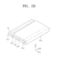
- FIG. 2B is a perspective view showing a foldable display in a folded state according to an exemplary embodiment.
- the foldable display includes a first display area DA 1 , a second display area DA 2 , and a folding area FA.
- the foldable display can also include two or more folding areas.
- the folding area FA is interposed between the first and second display areas DA 1 and DA 2 .
- a folding axis FX is defined in the folding area FA.
- the folding axis FX serves as a rotation axis when the foldable display is folded.
- the foldable display includes a display surface DS on which an image IM is displayed.
- the display surface DS includes a display surface of the first display area DA 1 , a display surface of the second display area DA 2 , and a display surface of the folding area FA.
- a first direction DR 1 and a second direction DR 2 define the display surface DS when the foldable display is unfolded.
- a third direction DR 3 indicates the thickness direction of the foldable display and the second direction DR 2 indicates the direction in which the folding axis FX extends.
- the foldable display can be folded along the folding axis FX such that the display surface of the first display area DA 1 faces the display surface of the second display area DA 2 .
- the configuration of the foldable display in which the foldable display folded such that the display surfaces of different areas face each other is referred to as an inner folding.
- the foldable display when the first display area DA 1 is rotated in a clockwise direction with respect to the folding axis FX, the foldable display is inner folded.
- the folding axis FX is defined at a center of the foldable display along the first direction DR 1 .
- the foldable display can be folded with respect to the folding axis FX to allow the display surfaces of the first and second display areas DA 1 and DA 2 are toward the outside of the foldable display.
- the folded state allowing the display surfaces of the different areas to face the outside of the foldable display is referred to as an outer folding.
- an image IM can be displayed.
- the image IM can be displayed in the display surface of the folding area FA exposed to the outside.
- the image IM can be displayed when the foldable display is in an unfolded state.
- the first display area DA 1 , the second display area DA 2 , and the folding area FA can respectively display images including independent information or respectively display different portions of one image including continuous information, for example, a single image can be displayed by the first and second display areas DA 1 and DA 2 and the folding area FA.
- the foldable display can include a plurality of folding areas FA 1 and FA 2 .
- the foldable display including two folding areas FA 1 and FA 2 will be described.
- the foldable display includes first, second, and third display areas DA 1 , DA 2 , and DA 3 and first and second folding areas FA 1 and FA 2 .
- first folding area FA 1 is interposed between the first and second display areas DA 1 and DA 2
- second folding area FA 2 is interposed between the second and third display areas DA 2 and DA 3 .
- First and second folding axes FX 1 and FX 2 are respectively defined in the first and second folding areas FA 1 and FA 2 .
- the foldable display can be inner-folded or outer-folded.
- the foldable display can be inner-folded in the first folding area FA 1 along the first folding axis FX 1 and inner-folded in the second folding area FA 2 along the second axis FX 2 .
- the image IM can be displayed by the foldable display.
- the image IM can be displayed by the display surface of the first folding area FA 1 and the display surface of the second folding area FA 2 , which are exposed to the outside.
- FIG. 3A is a perspective view showing a foldable display according to an exemplary embodiment.
- FIG. 3B is an exploded perspective view showing a foldable display according to an exemplary embodiment.
- FIG. 3C is a perspective view showing a hinge member or hinge 230 according to an exemplary embodiment.
- FIG. 3D is an exploded perspective view showing the hinge member 230 according to an exemplary embodiment.
- FIG. 3E is a side view showing the operation of the hinge member 230 according to an exemplary embodiment.
- the hinge member 230 shown in FIGS. 3A to 3E can be applied to the first and second folding areas FA 1 and FA 2 shown in FIGS. 2A and 2B .
- the foldable display includes a flexible display module 100 (hereinafter, referred to as a display module) and a housing 200 .
- the display module 100 is partially or entirely connected to the housing 200 .
- the connective structure connecting the display module 100 and the housing 200 should not be limited to a specific structure.
- the housing 200 can provides a substantially flat plane surface on which the display module 100 is arranged.
- the housing 200 defines a predetermined space and the display module 100 is accommodated in the predetermined space.
- the housing 200 defines a stepped space therein and the display module 100 is accommodated in the stepped space.
- the display module 100 can be entirely rolled or folded at a specific area.
- the display module 100 includes at least a flexible display panel and various functional members.
- the display panel can be an organic light-emitting diode (OLED) display panel, an electrophoretic display (EPD) panel, or an electrowetting display (EWD) panel.
- the functional members can include a protective member, an optical member, and a touch panel.
- the display module 100 includes a first area 110 , a second area 120 , and a third area 130 respectively corresponding to the first display area DA 1 , the second display area DA 2 , and the folding area FA, which are described with reference to FIGS. 1A to 1C .
- the first area 110 , the second area 120 , and the third area 130 are virtual areas separated from each other by the housing 200 .
- the housing 200 includes a plurality of sections with are connected to each other.
- the housing 200 includes a first supporting member or a first support 210 , a second supporting member or a second support 220 arranged to be spaced from the first supporting member 210 , and the hinge member 230 connecting the first and second supporting members 210 and 220 .
- the number of the supporting members corresponds to the number of the display areas DA 1 and DA 2 .
- the first and second supporting members 210 and 220 respectively support the first and second areas 110 and 120 and are respectively connected to the first and second areas 110 and 120 .
- Each of the first and second supporting members 210 and 220 can includes a plurality of sections that are connected to each other or can be integrally formed in a single unitary and individual unit via, for example, injection molding or extrusion molding.
- FIGS. 3A and 3B show two hinge members 230 spaced apart from each other in the second direction DR 2 .
- the number of the hinge members 230 should not be limited to two.
- Each of the two hinge members 230 connects the first and second supporting members 210 and 220 to each other.
- One end of each of the two hinge members 230 is connected to the first supporting member 210 and the other end of each of the two hinge members 230 is connected to the second supporting member 220 .
- the hinge member 230 will be described in detail with reference to FIGS. 3C to 3E .
- the hinge member 230 includes a plurality of bodies BD 1 , BD 2 , and BD 3 that are connected to each other.
- FIGS. 3C to 3E show an embodiment of the hinge member 230 that includes three bodies.
- the first body BD 1 includes a connection portion CT 1 and a fixing portion CP 1 .
- the connection portion CT 1 and the fixing portion CP 1 can be integrally formed in a single unitary and individual unit or can be separately formed and connected to each other.
- the connection portion CT 1 includes a first guide line SLT 1 - 1 and a second guide line SLT 1 - 2 .
- One of the first and second guide lines SLT 1 - 1 and SLT 1 - 2 has a straight line shape and the other of the first and second guide lines SLT 1 - 1 and SLT 1 - 2 has a curved line shape.
- the connection portion CT 1 includes a bottom BP 1 , a first sidewall SW 1 - 1 , and a second sidewall SW 1 - 2 .
- the first sidewall SW 1 - 1 is protruded from the bottom BP 1 and the first guide line SLT 1 - 1 is defined in the first sidewall SW 1 - 1 .
- the second sidewall SW 1 - 2 is protruded from the bottom BP 1 and the second guide line SLT 1 - 2 is defined in the second sidewall SW 1 - 2 .
- the second sidewall SW 1 - 2 is spaced apart from the first sidewall SW 1 - 1 in the second direction DR 2 and faces the first sidewall SW 1 - 1 .
- the first guide line SLT 1 - 1 corresponds to a slit formed through the first sidewall SW 1 - 1 and the second guide line SLT 1 - 2 corresponds to a slit formed through the second sidewall SW 1 - 2 .
- the first and second guide lines SLT 1 - 1 and SLT 1 - 2 should not be limited to the slit as long as the first and second guide lines SLT 1 - 1 and SLT 1 - 2 guide the rotation of the first and second bodies DB 1 and BD 2 .
- the first and second guide lines SLT 1 - 1 and SLT 1 - 2 can be grooves respectively defined in an inner surface of the first sidewall SW 1 - 1 and an inner surface of the second sidewall SW 1 - 2 .
- the first guide line SLT 1 - 1 crosses the second guide line SLT 1 - 2 when viewed in a plan view defined by the first and third directions DR 1 and DR 3 .
- the second guide line SLT 1 - 2 has the curved line shape extending from an upper portion of the second sidewall SW 1 - 2 to a lower portion of the second sidewall SW 1 - 2 .
- the first guide line SLT 1 - 1 has the straight line shape extending from a left portion of the first sidewall SW 1 - 1 to a right portion of the first sidewall SW 1 - 1 .
- the fixing portion CP 1 is connected to the bottom BP 1 , the first sidewall SW 1 - 1 , and the second sidewall SW 1 - 2 .
- the hinge member 230 is connected to the first supporting member 210 through the fixing portion CP 1 .
- the fixing portion CP 1 can be omitted.
- the connection portion CT 1 can be directly connected to the first supporting member 210 .
- the bottom BP 1 of the connection portion CT 1 can be omitted.
- the first and second sidewalls SW 1 - 1 and SW 1 - 2 can be the only elements connected to the fixing member CT 1 or can be directly connected to the first supporting member 210 .
- the second body BD 2 includes a rotation portion RX 2 , a first axle RX 2 - 1 , a second axle RX 2 - 2 , and a connection portion CT 2 .
- the first axle RX 2 - 1 is engaged with one surface of the rotation portion RX 2 and the second axle RX 2 - 2 is engaged with the other surface RX 2 -S 2 of the rotation portion RX 2 .
- the one surface of the rotation portion RX 2 not illustrated in FIG. 3D .
- the one surface of the rotation portion RX 2 and the other surface RX 2 -S 2 of the rotation portion RX 2 oppose each other in the second direction DR 2 .
- a first insertion hole H 2 - 1 engaged with the first axle RX 2 - 1 is defined through the one surface of the rotation portion RX 2 and a second insertion hole H 2 - 2 engaged with the second axle RX 2 - 2 is defined through the other surface RX 2 -S 2 of the rotation portion RX 2 .
- the rotation portion RX 2 is inserted into a space defined by the connection portion CT 1 of the first body BD 1 , i.e., by the first and second sidewalls SW 1 - 1 and SW 1 - 2 .
- the rotation portion RX 2 includes a curved surface RX 2 -SC connecting the one surface and the other surface RX 2 -S 2 of the rotation portion RX 2 .
- the first axle RX 2 - 1 is inserted into the first insertion hole H 2 - 1 through the first guide line SLT 1 - 1 and the second axle RX 2 - 2 is inserted into the second insertion hole H 2 - 2 through the second guide line SLT 1 - 2 .
- the first and second axles RX 2 - 1 and RX 2 - 2 are formed in different positions from each other.
- a line extending through a central axis the first axle RX 2 - 1 and a line extending through a central axis of the second axle RX 2 - 2 are substantially parallel to the second direction DR 2 but do not overlap each other.
- the connection portion CT 2 includes a bottom BP 2 , a first sidewall SW 2 - 1 , and a second sidewall SW 2 - 2 , which are connected to the rotation portion RX 2 .
- the bottom BP 2 is omitted.
- First and second guide lines SLT 2 - 1 and SLT 2 - 2 are respectively defined in the first and second sidewalls SW 2 - 1 and SW 2 - 2 .
- the first and second sidewalls SW 2 - 1 and SW 2 - 2 respectively correspond to the first and second sidewalls SW 1 - 1 and SW 1 - 2 of the first body BD 1 .
- the first and second guide lines SLT 2 - 1 and SLT 2 - 2 respectively correspond to the first and second guide lines SLT 1 - 1 and SLT 1 - 2 of the first body BD 1 .
- the connection portion CT 2 of the second body BD 2 can have substantially the same structure and functions as that of the first body BD 1 , and thus details thereof will be omitted.
- the third body BD 3 includes a rotation portion RX 3 , a first axle RX 3 - 1 , a second axle RX 3 - 2 , and a fixing portion CP 3 .
- the first axle RX 3 - 1 is engaged with one surface of the rotation portion RX 3 and the second axle RX 3 - 2 is engaged with the other surface RX 3 -S 2 of the rotation portion RX 3 .
- the one surface of the rotation portion RX 3 and the other surface RX 3 -S 2 of the rotation portion RX 3 oppose each other in the second direction DR 2 .
- a first insertion hole H 3 - 1 engaged with the first axle RX 3 - 1 is defined through the one surface of the rotation portion RX 3 and a second insertion hole H 3 - 2 engaged with the second axle RX 3 - 2 is defined through the other surface RX 3 -S 2 of the rotation portion RX 3 .
- the rotation portion RX 3 is inserted into a space defined by the connection portion CT 2 of the second body BD 2 , i.e., by the first and second sidewalls SW 2 - 1 and SW 2 - 2 .
- the rotation portion RX 3 includes a curved surface RX 3 -SC connecting the one surface and the other surface RX 3 -S 2 of the rotation portion RX 3 .
- the first axle RX 3 - 1 is inserted into the first insertion hole H 3 - 1 through the first guide line SLT 2 - 1 and the second axle RX 3 - 2 is inserted into the second insertion hole H 3 - 2 through the second guide line SLT 2 - 2 .
- the hinge member 230 is connected to the second supporting member 220 by the fixing portion CP 3 .
- the fixing portion CP 3 has a stepped shape.
- the second body BD 2 is omitted, and in these embodiments, the third body BD 3 can be directly connected to the first body BD 1 .
- the rotation portion RX 3 of the third body BD 3 can be inserted into the space defined by the first and second sidewalls SW 1 - 1 and SW 1 - 2 .
- the first, second, and third bodies BD 1 , BD 2 , and BD 3 are aligned in the first direction DR 1 .
- the first and second axles RX 2 - 1 and RX 2 - 2 of the second body BD 2 are arranged at one end, e.g., the left end as illustrated in FIG. 3E , of the first and second guide lines SLT 1 - 1 and SLT 1 - 2 of the first body BD 1 .
- the first and second axles RX 3 - 1 and RX 3 - 2 of the third body BD 3 are arranged at one end, e.g., the left end as illustrated in FIG. 3E , of the first and second guide lines SLT 2 - 1 and SLT 2 - 2 of the second body BD 2 .
- the first and second axles RX 2 - 1 and RX 2 - 2 of the second body BD 2 respectively move along the first and second guide lines SLT 1 - 1 and SLT 1 - 2 of the first body BD 1 .
- the rotation portion RX 2 of the second body BD 2 is rotated, the first and second axles RX 2 - 1 and RX 2 - 2 of the second body BD 2 move to the other end, e.g., the right end as illustrated in FIG. 3E , of the first and second guide lines SLT 1 - 1 and SLT 1 - 2 of the first body BD 1 .
- the first and second axles RX 3 - 1 and RX 3 - 2 of the third body BD 3 move to the other end, e.g., the right end as illustrated in FIG. 3E , of the first and second guide lines SLT 2 - 1 and SLT 2 - 2 of the second body BD 2 .
- the display module 100 is folded while the two axles RX 2 - 1 , RX 2 - 2 , RX 3 - 1 , and RX 3 - 2 of each of the second and third bodies BD 1 and BD 2 move along two guide lines SLT 1 - 1 , SLT 1 - 2 , SLT 2 - 1 , and SLT 2 - 2 of a corresponding body of the first and second bodies BD 1 and BD 2 , the length of the folding area FA, which is in the folded state, does not become less than that of the folding area FA, which is in the unfolded state. That is, the folding area FA maintains a substantially constant length due to the structure of the housing 200 (refer to FIGS. 3A and 3B ).
- the length of the folding area FA generally refers to the length in the second direction DR 2 .
- the folding area FA in the folded state can have a second length L 2 that is substantially equal to the first length L 1 . Accordingly, the display module 100 arranged inside the housing 200 can be inner-folded while maintaining the constant length thereof. That is, the display module 100 can be stably protected by the housing 200 without compressing or extending the length of the display module 100 .
- FIG. 4A is a perspective view showing a hinge member 230 - 1 according to an exemplary embodiment.
- FIG. 4B is an exploded perspective view showing the hinge member 230 - 1 according to an exemplary embodiment.
- FIG. 4C is a side view showing the operation of the hinge member 230 - 1 according to an exemplary embodiment.
- the same reference numerals denote the same elements in FIGS. 3A to 3E , and thus detailed descriptions of the same elements will be omitted.
- the hinge member 230 - 1 described hereinafter is arranged in the folding area FA and the configuration of the housing 200 should not be limited to a specific structure.
- the hinge member 230 - 1 includes a first body BD 10 , a second body BD 20 , and a third body BD 30 .
- the second and third bodies BD 20 and BD 30 are connected to the first body BD 10 .
- the first body BD 10 includes a rotation portion RX, a first axle RX 2 - 1 engaged with one surface of the rotation portion RX, a second axle RX 2 - 2 engaged with the other surface RX-S 2 of the rotation portion RX, a third axle RX 3 - 1 engaged with the one surface of the rotation portion RX and spaced apart from the first axle RX 2 - 1 , and a fourth axle RX 3 - 2 engaged with the other surface RX-S 2 of the rotation portion RX and spaced apart from the second axle RX 2 - 2 .
- First and third insertion holes H 2 - 1 and H 3 - 1 are respectively engaged with the first and third axles RX 2 - 1 and RX 3 - 1 and are defined through the one surface of the rotation portion RX.
- Second and fourth insertion holes H 2 - 2 and H 3 - 2 are respectively engaged with the second and fourth axles RX 2 - 2 and RX 3 - 2 and are defined through the other surface RX-S 2 of the rotation portion RX.
- the second body BD 20 includes a fixing portion CP 2 and a connection portion CT 2 .
- the hinge member 230 - 1 is connected to the first supporting member 210 (refer to FIGS. 3A and 3B ) by the fixing portion CP 2 .
- the fixing portion CP 2 is omitted.
- the connection portion CT 2 includes a bottom BP 2 , a first sidewall SW 2 - 1 , and a second sidewall SW 2 - 2 .
- the bottom BP 2 is omitted.
- the first sidewall SW 2 - 1 is protruded from the bottom BP 2 and the first guide line SLT 2 - 1 is defined in the first sidewall SW 2 - 1 .
- the second sidewall SW 2 - 2 is protruded from the bottom BP 2 and the second guide line SLT 2 - 2 is defined in the second sidewall SW 2 - 2 .
- One of the first and second guide lines SLT 2 - 1 and SLT 2 - 2 has a straight line shape and the other of the first and second guide lines SLT 2 - 1 and SLT 2 - 2 has a curved line shape.
- FIG. 4A shows the second guide line SLT 2 - 2 as having the curved line shape.
- the first and second guide lines SLT 2 - 1 and SLT 2 - 2 have a slit shape.
- the first guide line SLT 2 - 1 crosses the second guide line SLT 2 - 2 when viewed in the first and second sidewalls SW 2 - 1 and SW 2 - 2 .
- the second guide line SLT 2 - 2 has a curved line shape extending from an upper portion of the second sidewall SW 2 - 2 to a lower portion of the second sidewall SW 2 - 2 .
- the first guide line SLT 2 - 1 has a substantially straight line shape extending from a left portion of the first sidewall SW 2 - 1 to a right portion of the first sidewall SW 2 - 1 .
- the third body BD 30 includes a fixing portion CP 3 and a connection portion CT 3 .
- the third body BD 30 has substantially the same structure and functions as that of the second body BD 20 , and thus detailed descriptions of the third body BD 30 will be omitted.
- the hinge member 230 - 1 is connected to the second supporting member 220 (refer to FIGS. 3A and 3B ) by the fixing portion CP 3 .
- the third body BD 30 includes a bottom BP 3 , a first sidewall SW 3 - 1 , and a second sidewall SW 3 - 2 .
- a first guide line SLT 3 - 1 is defined through the first sidewall SW 3 - 1 and a second guide line SLT 3 - 2 is defined through the second sidewall SW 3 - 2 .
- the first guide line SLT 3 - 1 crosses the second guide line SLT 3 - 2 when viewed in the first and second sidewalls SW 3 - 1 and SW 3 - 2 .
- the second guide line SLT 3 - 2 has a curved line shape extending from an upper portion of the second sidewall SW 3 - 2 to a lower portion of the second sidewall SW 3 - 2 .
- the first guide line SLT 3 - 1 has a substantially straight line shape extending from a left portion of the first sidewall SW 3 - 1 to a right portion of the first sidewall SW 3 - 1 .
- the second guide line SLT 2 - 2 of the second body BD 20 and the second guide line SLT 3 - 2 of the third body BD 30 have a substantially mirror-inverted shape when viewed in a plan view defined by the first and third directions DR 1 and DR 3 .
- the first, second, and third bodies BD 10 , BD 20 , and BD 30 are aligned in the first direction DR 1 .
- the first and second axles RX 2 - 1 and RX 2 - 2 are arranged at one end, e.g., the left end as illustrated in FIG. 4C , of the first and second guide lines SLT 2 - 1 and SLT 2 - 2 of the second body BD 20 .
- the third and fourth axles RX 3 - 1 and RX 3 - 2 are arranged at one end, e.g., the right end as illustrated in FIG. 4C , of the first and second guide lines SLT 3 - 1 and SLT 3 - 2 of the third body BD 3 .
- the first and second axles RX 2 - 1 and RX 2 - 2 respectively move along the first and second guide lines SLT 2 - 1 and SLT 2 - 2 of the second body BD 20 .
- the rotation portion RX is rotated, the first and second axles RX 2 - 1 and RX 2 - 2 move to the other end, e.g., the right end as illustrated in FIG. 4C , of the first and second guide lines SLT 2 - 1 and SLT 2 - 2 of the second body BD 20 .
- the third body BD 30 is rotated, the third and fourth axles RX 3 - 1 and RX 3 - 2 move to the other end, e.g., the left end as illustrated in FIG. 4C , of the first and second guide lines SLT 3 - 1 and SLT 3 - 2 of the third body BD 30 .
- the foldable display is folded while the four axles RX 2 - 1 , RX 2 - 2 , RX 3 - 1 , and RX 3 - 2 respectively move along the guide lines SLT 2 - 1 , SLT 2 - 2 , SLT 3 - 1 , and SLT 3 - 2 , the length of the folding area FA in the folded state does not become less than that of the folding area FA in the unfolded state. That is, the folding area FA maintains a substantially constant length due to the structure of the housing 200 (refer to FIGS. 3A and 3B ).
- FIG. 5A is a perspective view showing a foldable display according to an exemplary embodiment.
- FIG. 5B is an exploded perspective view showing a foldable display according to an exemplary embodiment.
- FIG. 5C is an exploded perspective view showing a hinge member according to an exemplary embodiment.
- FIG. 5D is a perspective view showing the operation of a hinge member according to an exemplary embodiment.
- the same reference numerals denote the same elements in FIGS. 3A to 4C , and thus detailed descriptions of the same elements will be omitted.
- the foldable display includes a flexible display module 100 (hereinafter, referred to as a display module) and a housing 200 .
- the display module includes two display areas 110 and 120 and one folding area 130 .
- the housing 200 includes a first supporting member 210 , a second supporting member 220 arranged to be spaced apart from the first supporting member 210 , and a hinge member 230 - 2 connecting the first and second supporting members 210 and 220 .
- the first and second supporting members 210 and 220 respectively support the display areas 110 and 120 and are respectively connected to the display areas 110 and 120 .
- FIGS. 5A and 5B show two hinge members 230 - 2 spaced apart from each other in the second direction DR 2 .
- the hinge member 230 - 2 includes first, second, and third bodies BD 100 , BD 200 , and BD 300 .
- Each of the second and third bodies BD 200 and BD 300 is engaged with the first body BD 100 to be rotatable.
- the first body BD 100 includes a bottom portion BP, a rotation arm RX-A, a first connection portion CT 1 , and a second connection portion CT 2 .
- the bottom BP, the first connection portion CT 1 , and the second connection portion CT 2 can be integrally formed in a single unitary and individual unit or can be separately formed to be connected to each other.
- a rotation axle RX-B, with which the rotation arm RX-A is engaged, is formed on the bottom portion BP.
- the first connection portion CT 1 and the second connection portion CT 2 are arranged on the bottom portion BP and spaced apart from each other in the second direction DR 2 .
- the first connection portion CT 1 includes a first guide line SLT 2 - 1 and a first guide slit SLT 2 - 2 .
- the second connection portion CT 2 includes a second guide line SLT 3 - 1 and a second guide slit SLT 3 - 2 .
- the first and second guide slits SLT 2 - 2 and SLT 3 - 2 are substantially parallel to each other.
- the first guide line SLT 2 - 1 and the second guide line SLT 3 - 1 have a curved line shape.
- the first guide line SLT 2 - 1 crosses the second guide line SLT 3 - 1
- the first guide line SLT 2 - 1 and the second guide line SLT 3 - 1 have a substantially mirror-inverted shape with respect to the third direction DR 3 .
- the first and second guide lines SLT 2 - 1 and SLT 3 - 1 have a slit shape, but they should not be limited to the slit shape. That is, the first and second guide lines SLT 2 - 1 and SLT 3 - 1 have a groove shape.
- the first connection portion CT 1 includes a first sidewall SW 2 - 1 and a second sidewall SW 2 - 2 .
- the first sidewall SW 2 - 1 is protruded from the bottom portion BP and the first guide line SLT 2 - 1 is defined in the first sidewall SW 2 - 1 .
- the second sidewall SW 2 - 2 is protruded from the bottom portion BP and the first guide slit SLT 2 - 2 is defined in the second sidewall SW 2 - 2 .
- the second connection portion CT 2 includes a third sidewall SW 3 - 1 and a fourth sidewall SW 3 - 2 .
- the second guide line SLT 3 - 1 is defined in the third sidewall SW 3 - 1 and the second guide slit SLT 3 - 2 is defined in the fourth sidewall SW 3 - 2 .
- the second and fourth sidewalls SW 2 - 2 and SW 3 - 2 are arranged closer to the rotation axle RX-B than the first and third sidewalls SW 2 - 1 and SW 3 - 1 .
- the rotation arm RX-A is includes a through-hole RX-AR, into which the rotation axle RX-B is inserted, and third and fourth guide lines RX-AS 1 and RX-AS 2 defined such that the through-hole RX-AR is interposed between the third and fourth guide lines RX-AS 1 and RX-AS 2 .
- FIG. 5C shows the third and fourth guide lines RX-AS 1 and RX-AS 2 having a slit shape.
- a second axle RX 2 - 2 of the second body BD 200 and a second axle RX 3 - 2 of the third body BD 300 are respectively engaged with the third and fourth guide lines RX-AS 1 and RX-AS 2 .
- the second body BD 200 includes a fixing portion CP 2 , a rotation portion RX 2 , a first axle RX 2 - 1 , and the second axle RX 2 - 2 .
- the fixing portion CP 2 is connected to the first supporting member 210 .
- the first axle RX 2 - 1 is engaged with one surface of the rotation portion RX 2 and the first guide line SLT 2 - 1 .
- the second axle RX 2 - 2 is engaged with the other surface RX 2 -S 2 of the rotation portion RX 2 and the rotation arm RX-A.
- the second axle RX 2 - 2 is engaged with the third guide line RX-AS 1 of the rotation arm RX-A after passing through the first guide slit SLT 2 - 2 .
- the second axle RX 2 - 2 can further include a protrusion RX 2 - 2 P engaged with the third guide line RX-AS 1 of the rotation arm RX-A.
- the third body BD 300 includes a fixing portion CP 3 , a rotation portion RX 3 , a first axle RX 3 - 1 , and the second axle RX 3 - 2 .
- the fixing portion CP 3 is connected to the second supporting member 220 .
- the first axle RX 3 - 1 is engaged with one surface RX 3 -S 1 of the rotation portion RX 3 and the first guide line SLT 3 - 1 .
- the second axle RX 3 - 2 is engaged with the other surface of the rotation portion RX 3 and the rotation arm RX-A.
- the second axle RX 3 - 2 is engaged with the fourth guide line RX-AS 2 of the rotation arm RX-A after passing through the second guide slit SLT 3 - 2 .
- the second axle RX 3 - 2 can further include a protrusion RX 3 - 2 P engaged with the fourth guide line RX-AS 2 of the rotation arm RX-A.
- the rotation arm RX-A is aligned substantially parallel to the second direction DR 2 .
- the first and second axles RX 2 - 1 and RX 2 - 2 of the second body BD 200 are arranged at one end of each of the first guide line SLT 2 - 1 and the first guide slit SLT 2 - 2 .
- the first and second axles RX 3 - 1 and RX 3 - 2 of the third body BD 300 are arranged at one end of each of the second guide line SLT 3 - 1 and the second guide slit SLT 3 - 2 .
- the first axle RX 2 - 1 of the second body BD 200 and the first axle RX 3 - 1 of the third body BD 300 can be aligned on substantially the same line.
- the rotation arm RX-A When the foldable display is folded, the rotation arm RX-A is rotated in a counter-clockwise direction.
- the first and second axles RX 2 - 1 and RX 2 - 2 of the second body BD 200 respectively move along the first guide line SLT 2 - 1 and the first guide slit SLT 2 - 2 of the second body BD 200 .
- the rotation portion RX of the second body BD 200 When the rotation portion RX of the second body BD 200 is rotated, the first and second axles RX 2 - 1 and RX 2 - 2 of the second body BD 200 move to the other ends of the first guide line SLT 2 - 1 and the first guide slit SLT 2 - 2 .
- the foldable display is folded while the four axles RX 2 - 1 , RX 2 - 2 , RX 3 - 1 , and RX 3 - 2 respectively move along the guide lines SLT 2 - 1 and SLT 3 - 1 and the guide slits SLT 2 - 2 and SLT 3 - 2 , the length of the folding area FA in the folded state does not become less than that of the folding area FA in the unfolded state. That is, the folding area FA of the housing 200 (refer to FIGS. 5A and 5B ) maintains a substantially constant length.
Abstract
A foldable display is disclosed. In one aspect, the foldable display includes a housing comprising first and second supports and a hinge connecting the first and second supports to each other. The foldable display also includes a flexible display module connected to the first and second supports. The hinge includes a first body including a rotation portion and first and second axles engaged with the rotation portion. The hinge further includes a second body including a connection portion. First and second guide lines are defined in the connection portion and are respectively engaged with the first and second axles. The second guide line has a curved shape.
Description
This U.S. non-provisional patent application claims priority under 35 U.S.C. §119 of Korean Patent Application No. 10-2015-0006987, filed on Jan. 14, 2015, the contents of which are hereby incorporated by reference in its entirety.
Field
The present disclosure generally relates to a foldable display.
Description of the Related Technology
Rollable or foldable displays include a flexible display module. Flexible display modules, which are bendable or foldable, have been undergoing active research and development. Flexible display modules include a flexible display panel and various supportive functional components. Such flexible display panels include a base substrate, various functional layers formed over the base substrate and pixels formed over the base substrate.
One inventive aspect is a foldable display including a hinge member.
Another aspect is a foldable display that can reduce deformation thereof.
Another aspect is a foldable display including a housing and a flexible display module. The housing includes a first supporting member, a second supporting member arranged to be spaced apart from the first supporting member, and a hinge member connecting the first and second supporting members. The flexible display module is connected to the first and second supporting members.
The hinge member includes a first body and a second body. The first body includes a rotation portion, a first axle engaged with one surface of the rotation portion, and a second axle engaged with the other surface of the rotation portion. The second body includes a connection portion including a first guide line facing the one surface of the rotation portion of the first body and engaged with the first axle and a second guide line facing the other surface of the rotation portion of the first body, engaged with the second axle, and having a curved line shape.
The second body further includes a fixing portion connected to the connection portion of the second body and connected to the first supporting member.
The connection portion of the second body includes a first sidewall in which the first guide line is defined and a second sidewall in which the second guide line is defined. The second sidewall is spaced apart from the first sidewall to face the first sidewall.
The first guide line is a first slit formed through the first sidewall and the second guide line is a second slit formed through the second sidewall.
The first body further includes a fixing portion connected to the rotation portion of the first body, and the fixing portion of the first body is connected to the second supporting member.
The hinge member further includes a third body. The third body includes a rotation portion, a third axle engaged with one surface of the rotation portion, and a fourth axle engaged with the other surface of the rotation portion.
The first body further includes a connection portion including a third guide line facing the one surface of the rotation portion of the third body and engaged with the third axle and a fourth guide line facing the other surface of the rotation portion of the third body and engaged with the fourth axle.
The connection portion of the first body includes a third sidewall in which the third guide line is defined and a fourth sidewall in which the fourth guide line is defined. The fourth sidewall is spaced apart from the third sidewall to face the third sidewall.
The third guide line is a third slit formed through the third sidewall and the fourth guide line is a fourth slit formed through the fourth sidewall.
The third body further includes a fixing portion connected to the rotation portion of the third body, and the fixing portion of the third body is connected to the second supporting member.
The hinge member can include a first body, a second body, and a third body. The first body includes a first axle engaged with one surface of the rotation portion, a second axle engaged with the other surface of the rotation portion, a third axle engaged with the one surface of the rotation portion and spaced apart from the first axle, and a fourth axle engaged with the other surface of the rotation portion and spaced apart from the second axle.
The second body includes a connection portion including a first guide line facing the one surface of the rotation portion and engaged with the first axle and a second guide line facing the other surface of the rotation portion and engaged with the second axle.
The third body includes a connection portion including a third guide line facing the one surface of the rotation portion and engaged with the third axle and a fourth guide line facing the other surface of the rotation portion and engaged with the fourth axle.
One guide line of the first and second guide lines has a curved line shape and one guide line of the third and fourth guide lines has the curved line shape.
The connection portion of the second body includes a first sidewall in which the first guide line is defined and a second sidewall in which the second guide line is defined. The connection portion of the third body includes a third sidewall in which the third guide line is defined and a fourth sidewall in which the fourth guide line is defined.
The second body further includes a first fixing portion connected to the first and second sidewalls and connected to the first supporting member. The third body further includes a second fixing portion connected to the third and fourth sidewalls and connected to the second supporting member.
The guide line having the curved line shape of the first and second guide lines and the guide line having the curved line shape of the third and fourth guide lines have a mirror-inverted shape when viewed in the first, second, third, and fourth sidewalls.
Each of the first, second, third, and fourth guide lines is a slit formed through a corresponding sidewall among the first, second, third, and fourth sidewalls.
The hinge member can include a first body, a second body, and a third body. The first body includes a bottom portion provided with a rotation axle, a rotation arm engaged with the rotation axle, a first connection portion comprising a first guide line having a curved line shape and a first guide slit and being formed on the bottom portion, and a second connection portion including a second guide line having the curved line shape and a second guide slit and being formed on the bottom portion to be spaced apart from the first connection portion.
The second body includes a first rotation portion, a first axle engaged with one surface of the first rotation portion and the first guide line and a second axle engaged with the other surface of the first rotation portion and engaged with the rotation arm after passing through the first guide slit.
The third body includes a second rotation portion, a third axle engaged with one surface of the second rotation portion and the second guide line and a fourth axle engaged with the other surface of the second rotation portion and engaged with the rotation arm after passing through the second guide slit.
The first body further includes a first fixing portion engaged with the first rotation portion and engaged with the first supporting member. The second body further includes a second fixing portion connected to the second rotation portion and connected to the second supporting member.
The first connection portion includes a first sidewall in which the first guide line is defined and a second sidewall spaced apart from the first sidewall, in which the first guide slit is defined. The second connection portion includes a third sidewall protruded from the bottom portion, in which the second guide line is defined, and a fourth sidewall spaced apart from the third sidewall, in which the second guide slit is defined. The second and fourth sidewalls are arranged closer to the rotation axle than the first and third sidewalls.
The first guide line crosses the second guide line. The first and second guide slits are substantially parallel to each other.
The rotation arm is provided with a through-hole into which the rotation axle is inserted and third and fourth guide lines arranged such that the thru-hole is interposed between the third and fourth guide lines. The first axle further includes a first protrusion engaged with the third guide line, and the third axle further includes a second protrusion engaged with the fourth guide line.
Another aspect is a foldable display, comprising a housing comprising: i) a first support, ii) a second support spaced apart from the first support, and iii) a hinge connecting the first and second supports to each other; a flexible display module connected to the first and second supports, wherein the hinge comprises: a first body comprising: i) a rotation portion including first and second surfaces opposing each other, ii) a first axle engaged with the first surface of the rotation portion, and iii) a second axle engaged with the second surface of the rotation portion; and a second body comprising a connection portion including first and second surfaces opposing each other, wherein a first guide line is defined in the first surface of the connection portion and engaged with the first axle, wherein a second guide line is defined in the second surface of the connection portion and engaged with the second axle, and wherein the second guide line has a curved shape.
In exemplary embodiments, the second body further comprises a fixing portion connected to the connection portion of the second body and the first support. The connection portion of the second body can comprise a first sidewall in which the first guide line is defined; and a second sidewall in which the second guide line is defined, wherein the second sidewall is spaced apart from and opposes the first sidewall. The first guide line can be a first slit formed through the first sidewall and the second guide line can be a second slit formed through the second sidewall. The first body can further comprise a fixing portion connected to the rotation portion of the first body the second support.
In exemplary embodiments, the foldable display further comprises a third body comprising: i) a rotation portion including first and second surfaces opposing each other, ii) a third axle engaged with the first surface of the rotation portion, and iii) a fourth axle engaged with the second surface of the rotation portion, wherein the first body further comprises a connection portion including third and fourth surfaces opposing each other, wherein a third guide line is defined in the third surface of the connection portion and engaged with the third axle, and wherein a fourth guide line is defined in the fourth surface of the connection portion and engaged with the fourth axle.
In exemplary embodiments, the connection portion of the first body comprises a third sidewall in which the third guide line is defined; and a fourth sidewall in which the fourth guide line is defined, wherein the fourth sidewall is spaced apart from and opposes the third sidewall. The third guide line can be a third slit formed through the third sidewall and the fourth guide line can be a fourth slit formed through the fourth sidewall. The third body can further comprise a fixing portion connected to the rotation portion of the third body and the second supporting member.
Another aspect is a foldable display, comprising a housing comprising a first support, a second support, spaced apart from the first support, and a hinge connecting the first and second supports to each other; and a flexible display module connected to the first and second supports, wherein the hinge comprises: a first body having first and second surfaces opposing each other, wherein the first body comprises: i) a first axle engaged with the first surface of the first body, ii) a second axle engaged with the second surface of the first body, iii) a third axle engaged with the first surface of the first body and spaced apart from the first axle, and iv) a fourth axle engaged with the second surface of the first body and spaced apart from the second axle; a second body comprising a connection portion including: i) a first guide line facing the first surface of the first body and engaged with the first axle and ii) a second guide line facing the second surface of the first body and engaged with the second axle; and a third body comprising a connection portion including: i) a third guide line facing the first surface of the first body and engaged with the third axle and ii) a fourth guide line facing the second surface of the rotation portion and engaged with the fourth axle, wherein one of the first and second guide lines has a curved line shape and one of the third and fourth guide lines has a curved line shape.
In exemplary embodiments, the connection portion of the second body comprises a first sidewall in which the first guide line is defined; and a second sidewall in which the second guide line is defined, and wherein the connection portion of the third body comprises: a third sidewall in which the third guide line is defined; and a fourth sidewall in which the fourth guide line is defined. The second body can further comprise a first fixing portion connected to the first and second sidewalls and the first support and the third body can further comprise a second fixing portion connected to the third and fourth sidewalls and the second support.
In exemplary embodiments, the guide lines that have the curved line shapes have a substantially mirror-inverted shape. Each of the first, second, third, and fourth guide lines can be a slit formed through a corresponding sidewall among the first, second, third, and fourth sidewalls.
Another aspect is a foldable display, comprising a housing comprising a first support, a second support, spaced apart from the first support, and a hinge connecting the first and second supports to each other; and a flexible display module connected to the first and second supports, wherein the hinge comprises: a first body comprising: i) a bottom portion, ii) a rotation axle formed over the bottom portion, iii) a rotation arm engaged with the rotation axle, iv) a first connection portion including a first guide line having a curved line shape and a first guide slit and v) a second connection portion including a second guide line having the curved line shape and a second guide slit, wherein the first and second connection portions are formed over the bottom portion and are spaced apart from each other; a second body comprising: i) a first rotation portion including first and second surfaces opposing each other, ii) a first axle engaged with the first surface of the first rotation portion and the first guide line and iii) a second axle engaged with the second surface of the first rotation portion and the rotation arm after passing through the first guide slit; and a third body comprising: i) a second rotation portion including third and fourth surfaces opposing each other, ii) a third axle engaged with the third surface of the second rotation portion and the second guide line and iii) a fourth axle engaged with the fourth surface of the second rotation portion and the rotation arm after passing through the second guide slit.
In exemplary embodiments, the second body further comprises a first fixing portion connected to the first rotation portion and the first support and wherein the third body further comprises a second fixing portion connected to the second rotation portion and the second support.
In exemplary embodiments, the first connection portion comprises a first sidewall in which the first guide line is defined and a second sidewall spaced apart from the first sidewall, in which the first guide slit is defined, wherein the second connection portion comprises a third sidewall in which the second guide line is defined and a fourth sidewall spaced apart from the third sidewall, in which the second guide slit is defined, and wherein the second and fourth sidewalls are arranged closer to the rotation axle than the first and third sidewalls.
In exemplary embodiments, the first guide line crosses the second guide line. The first and second guide slits can be substantially parallel to each other. The rotation arm can have i) a though-hole into which the rotation axle is inserted and ii) third and fourth guide lines defined on opposing sides of the through-hole, the second axle can further comprise a first protrusion engaged with the third guide line, and the fourth axle can further comprise a second protrusion engaged with the fourth guide line.
According to at least one embodiment, the hinge member is operated when the foldable display is folded, and thus the deformation in the flexible display module can be reduced. The folding area is maintained at a substantially constant length by the housing since the flexible display module is folded by the two axles of the hinge member moving the two guide lines. Thus, the flexible display module can be stably protected by the housing.
The above and other advantages of the present disclosure will become readily apparent by reference to the following detailed description when considered in conjunction with the accompanying drawings.
It will be understood that when an element or layer is referred to as being “on”, “connected to” or “coupled to” another element or layer, it can be directly on, connected or coupled to the other element or layer or intervening elements or layers may also be present. In contrast, when an element is referred to as being “directly on,” “directly connected to” or “directly coupled to” another element or layer, there are no intervening elements or layers present. Like numbers refer to like elements throughout. As used herein, the term “and/or” includes any and all combinations of one or more of the associated listed items.
It will be understood that, although the terms first, second, etc. may be used herein to describe various elements, components, regions, layers and/or sections, these elements, components, regions, layers and/or sections should not be limited by these terms. These terms are only used to distinguish one element, component, region, layer or section from another element, component, region, layer or section. Thus, a first element, component, region, layer or section discussed below could be termed a second element, component, region, layer or section without departing from the teachings of the described technology.
Spatially relative terms, such as “beneath”, “below”, “lower”, “above”, “upper” and the like, may be used herein for ease of description to describe one element or feature's relationship to another element(s) or feature(s) as illustrated in the figures. It will be understood that the spatially relative terms are intended to encompass different orientations of the device in use or operation in addition to the orientation depicted in the figures. For example, if the device in the figures is turned over, elements described as “below” or “beneath” other elements or features would then be oriented “above” the other elements or features. Thus, the exemplary term “below” can encompass both an orientation of above and below. The device may be otherwise oriented (rotated 90 degrees or at other orientations) and the spatially relative descriptors used herein are to be interpreted accordingly.
The terminology used herein is for the purpose of describing particular embodiments only and is not intended to be limiting of the described technology. As used herein, the singular forms, “a”, “an” and “the” are intended to include the plural forms as well, unless the context clearly indicates otherwise. It will be further understood that the terms “includes” and/or “including”, when used in this specification, specify the presence of stated features, integers, steps, operations, elements, and/or components, but do not preclude the presence or addition of one or more other features, integers, steps, operations, elements, components, and/or groups thereof.
Unless otherwise defined, all terms (including technical and scientific terms) used herein have the same meaning as commonly understood by one of ordinary skill in the art to which the described technology belongs. It will be further understood that terms, such as those defined in commonly used dictionaries, should be interpreted as having a meaning that is consistent with their meaning in the context of the relevant art and will not be interpreted in an idealized or overly formal sense unless expressly so defined herein.
Hereinafter, the described technology will be explained in detail with reference to the accompanying drawings.
Referring to FIGS. 1A and 1B , the foldable display includes a first display area DA1, a second display area DA2, and a folding area FA. In contrast to the embodiment of the foldable display shown in FIGS. 1A and 1B , the foldable display can also include two or more folding areas.
The folding area FA is interposed between the first and second display areas DA1 and DA2. A folding axis FX is defined in the folding area FA. The folding axis FX serves as a rotation axis when the foldable display is folded.
The foldable display includes a display surface DS on which an image IM is displayed. The display surface DS includes a display surface of the first display area DA1, a display surface of the second display area DA2, and a display surface of the folding area FA. In the present exemplary embodiment, a first direction DR1 and a second direction DR2 define the display surface DS when the foldable display is unfolded. A third direction DR3 indicates the thickness direction of the foldable display and the second direction DR2 indicates the direction in which the folding axis FX extends.
Referring to FIG. 1B , the foldable display can be folded along the folding axis FX such that the display surface of the first display area DA1 faces the display surface of the second display area DA2. Hereinafter, the configuration of the foldable display in which the foldable display folded such that the display surfaces of different areas face each other is referred to as an inner folding. In the present exemplary embodiment, when the first display area DA1 is rotated in a clockwise direction with respect to the folding axis FX, the foldable display is inner folded. In some embodiments, to inner fold the foldable display such that the first display area DA1 is aligned with the second display area DA2, the folding axis FX is defined at a center of the foldable display along the first direction DR1.
Although not shown in figures, the foldable display can be folded with respect to the folding axis FX to allow the display surfaces of the first and second display areas DA1 and DA2 are toward the outside of the foldable display. Hereinafter, the folded state allowing the display surfaces of the different areas to face the outside of the foldable display is referred to as an outer folding.
Referring to FIGS. 1A and 1B , when the display surface of the first display area DA1 and the display surface of the second display area DA2 are exposed to the outside, an image IM can be displayed. In addition, the image IM can be displayed in the display surface of the folding area FA exposed to the outside. As shown in FIG. 1A , the image IM can be displayed when the foldable display is in an unfolded state. The first display area DA1, the second display area DA2, and the folding area FA can respectively display images including independent information or respectively display different portions of one image including continuous information, for example, a single image can be displayed by the first and second display areas DA1 and DA2 and the folding area FA.
Referring to FIGS. 2A and 2B , the foldable display can include a plurality of folding areas FA1 and FA2. In the present exemplary embodiment, the foldable display including two folding areas FA1 and FA2 will be described.
The foldable display includes first, second, and third display areas DA1, DA2, and DA3 and first and second folding areas FA1 and FA2. When the foldable display is in the unfolded state, the first folding area FA1 is interposed between the first and second display areas DA1 and DA2 and the second folding area FA2 is interposed between the second and third display areas DA2 and DA3. First and second folding axes FX1 and FX2 are respectively defined in the first and second folding areas FA1 and FA2. The foldable display can be inner-folded or outer-folded.
As shown in FIG. 2B , the foldable display can be inner-folded in the first folding area FA1 along the first folding axis FX1 and inner-folded in the second folding area FA2 along the second axis FX2. As shown in FIGS. 2A and 2B , when the display surface of the first display area DA1, the display surface of the second display area DA2, and the display surface of the third display area DA3 are exposed to the outside, the image IM can be displayed by the foldable display. In addition, the image IM can be displayed by the display surface of the first folding area FA1 and the display surface of the second folding area FA2, which are exposed to the outside.
The hinge member 230 shown in FIGS. 3A to 3E can be applied to the first and second folding areas FA1 and FA2 shown in FIGS. 2A and 2B .
Referring to FIGS. 3A and 3B , the foldable display includes a flexible display module 100 (hereinafter, referred to as a display module) and a housing 200. The display module 100 is partially or entirely connected to the housing 200. The connective structure connecting the display module 100 and the housing 200 should not be limited to a specific structure. For instance, the housing 200 can provides a substantially flat plane surface on which the display module 100 is arranged. In the present exemplary embodiment, the housing 200 defines a predetermined space and the display module 100 is accommodated in the predetermined space. The housing 200 defines a stepped space therein and the display module 100 is accommodated in the stepped space.
The display module 100 can be entirely rolled or folded at a specific area. The display module 100 includes at least a flexible display panel and various functional members. The display panel can be an organic light-emitting diode (OLED) display panel, an electrophoretic display (EPD) panel, or an electrowetting display (EWD) panel. The functional members can include a protective member, an optical member, and a touch panel.
The display module 100 includes a first area 110, a second area 120, and a third area 130 respectively corresponding to the first display area DA1, the second display area DA2, and the folding area FA, which are described with reference to FIGS. 1A to 1C . The first area 110, the second area 120, and the third area 130 are virtual areas separated from each other by the housing 200.
The housing 200 includes a plurality of sections with are connected to each other. The housing 200 includes a first supporting member or a first support 210, a second supporting member or a second support 220 arranged to be spaced from the first supporting member 210, and the hinge member 230 connecting the first and second supporting members 210 and 220. The number of the supporting members corresponds to the number of the display areas DA1 and DA2.
The first and second supporting members 210 and 220 respectively support the first and second areas 110 and 120 and are respectively connected to the first and second areas 110 and 120. Each of the first and second supporting members 210 and 220 can includes a plurality of sections that are connected to each other or can be integrally formed in a single unitary and individual unit via, for example, injection molding or extrusion molding.
Referring to FIGS. 3C and 3D , the hinge member 230 includes a plurality of bodies BD1, BD2, and BD3 that are connected to each other. FIGS. 3C to 3E show an embodiment of the hinge member 230 that includes three bodies.
The first body BD1 includes a connection portion CT1 and a fixing portion CP1. The connection portion CT1 and the fixing portion CP1 can be integrally formed in a single unitary and individual unit or can be separately formed and connected to each other. The connection portion CT1 includes a first guide line SLT1-1 and a second guide line SLT1-2. One of the first and second guide lines SLT1-1 and SLT1-2 has a straight line shape and the other of the first and second guide lines SLT1-1 and SLT1-2 has a curved line shape.
The connection portion CT1 includes a bottom BP1, a first sidewall SW1-1, and a second sidewall SW1-2. The first sidewall SW1-1 is protruded from the bottom BP1 and the first guide line SLT1-1 is defined in the first sidewall SW1-1. The second sidewall SW1-2 is protruded from the bottom BP1 and the second guide line SLT1-2 is defined in the second sidewall SW1-2. The second sidewall SW1-2 is spaced apart from the first sidewall SW1-1 in the second direction DR2 and faces the first sidewall SW1-1.
The first guide line SLT1-1 corresponds to a slit formed through the first sidewall SW1-1 and the second guide line SLT1-2 corresponds to a slit formed through the second sidewall SW1-2. The first and second guide lines SLT1-1 and SLT1-2 should not be limited to the slit as long as the first and second guide lines SLT1-1 and SLT1-2 guide the rotation of the first and second bodies DB1 and BD2. In the present exemplary embodiment, the first and second guide lines SLT1-1 and SLT1-2 can be grooves respectively defined in an inner surface of the first sidewall SW1-1 and an inner surface of the second sidewall SW1-2.
The first guide line SLT1-1 crosses the second guide line SLT1-2 when viewed in a plan view defined by the first and third directions DR1 and DR3. The second guide line SLT1-2 has the curved line shape extending from an upper portion of the second sidewall SW1-2 to a lower portion of the second sidewall SW1-2. The first guide line SLT1-1 has the straight line shape extending from a left portion of the first sidewall SW1-1 to a right portion of the first sidewall SW1-1.
The fixing portion CP1 is connected to the bottom BP1, the first sidewall SW1-1, and the second sidewall SW1-2. The hinge member 230 is connected to the first supporting member 210 through the fixing portion CP1. In some exemplary embodiment, the fixing portion CP1 can be omitted. In these embodiments, the connection portion CT1 can be directly connected to the first supporting member 210.
In some exemplary embodiments, the bottom BP1 of the connection portion CT1 can be omitted. In these embodiments, the first and second sidewalls SW1-1 and SW1-2 can be the only elements connected to the fixing member CT1 or can be directly connected to the first supporting member 210.
The second body BD2 includes a rotation portion RX2, a first axle RX2-1, a second axle RX2-2, and a connection portion CT2. The first axle RX2-1 is engaged with one surface of the rotation portion RX2 and the second axle RX2-2 is engaged with the other surface RX2-S2 of the rotation portion RX2. The one surface of the rotation portion RX2 not illustrated in FIG. 3D . The one surface of the rotation portion RX2 and the other surface RX2-S2 of the rotation portion RX2 oppose each other in the second direction DR2. A first insertion hole H2-1 engaged with the first axle RX2-1 is defined through the one surface of the rotation portion RX2 and a second insertion hole H2-2 engaged with the second axle RX2-2 is defined through the other surface RX2-S2 of the rotation portion RX2.
The rotation portion RX2 is inserted into a space defined by the connection portion CT1 of the first body BD1, i.e., by the first and second sidewalls SW1-1 and SW1-2. The rotation portion RX2 includes a curved surface RX2-SC connecting the one surface and the other surface RX2-S2 of the rotation portion RX2. The first axle RX2-1 is inserted into the first insertion hole H2-1 through the first guide line SLT1-1 and the second axle RX2-2 is inserted into the second insertion hole H2-2 through the second guide line SLT1-2. The first and second axles RX2-1 and RX2-2 are formed in different positions from each other. A line extending through a central axis the first axle RX2-1 and a line extending through a central axis of the second axle RX2-2 are substantially parallel to the second direction DR2 but do not overlap each other.
The connection portion CT2 includes a bottom BP2, a first sidewall SW2-1, and a second sidewall SW2-2, which are connected to the rotation portion RX2. In some exemplary embodiments, the bottom BP2 is omitted. First and second guide lines SLT2-1 and SLT2-2 are respectively defined in the first and second sidewalls SW2-1 and SW2-2. The first and second sidewalls SW2-1 and SW2-2 respectively correspond to the first and second sidewalls SW1-1 and SW1-2 of the first body BD1. The first and second guide lines SLT2-1 and SLT2-2 respectively correspond to the first and second guide lines SLT1-1 and SLT1-2 of the first body BD1. The connection portion CT2 of the second body BD2 can have substantially the same structure and functions as that of the first body BD1, and thus details thereof will be omitted.
The third body BD3 includes a rotation portion RX3, a first axle RX3-1, a second axle RX3-2, and a fixing portion CP3. The first axle RX3-1 is engaged with one surface of the rotation portion RX3 and the second axle RX3-2 is engaged with the other surface RX3-S2 of the rotation portion RX3. The one surface of the rotation portion RX3 and the other surface RX3-S2 of the rotation portion RX3 oppose each other in the second direction DR2. A first insertion hole H3-1 engaged with the first axle RX3-1 is defined through the one surface of the rotation portion RX3 and a second insertion hole H3-2 engaged with the second axle RX3-2 is defined through the other surface RX3-S2 of the rotation portion RX3.
The rotation portion RX3 is inserted into a space defined by the connection portion CT2 of the second body BD2, i.e., by the first and second sidewalls SW2-1 and SW2-2. The rotation portion RX3 includes a curved surface RX3-SC connecting the one surface and the other surface RX3-S2 of the rotation portion RX3. The first axle RX3-1 is inserted into the first insertion hole H3-1 through the first guide line SLT2-1 and the second axle RX3-2 is inserted into the second insertion hole H3-2 through the second guide line SLT2-2.
The hinge member 230 is connected to the second supporting member 220 by the fixing portion CP3. The fixing portion CP3 has a stepped shape.
In some exemplary embodiments, the second body BD2 is omitted, and in these embodiments, the third body BD3 can be directly connected to the first body BD1. The rotation portion RX3 of the third body BD3 can be inserted into the space defined by the first and second sidewalls SW1-1 and SW1-2.
Referring to FIG. 3E , when the display module 100 (refer to FIGS. 3A and 3B ) is in the unfolded state, the first, second, and third bodies BD1, BD2, and BD3 are aligned in the first direction DR1. The first and second axles RX2-1 and RX2-2 of the second body BD2 are arranged at one end, e.g., the left end as illustrated in FIG. 3E , of the first and second guide lines SLT1-1 and SLT1-2 of the first body BD1. The first and second axles RX3-1 and RX3-2 of the third body BD3 are arranged at one end, e.g., the left end as illustrated in FIG. 3E , of the first and second guide lines SLT2-1 and SLT2-2 of the second body BD2.
When the foldable display is folded by an external force, the first and second axles RX2-1 and RX2-2 of the second body BD2 respectively move along the first and second guide lines SLT1-1 and SLT1-2 of the first body BD1. When the rotation portion RX2 of the second body BD2 is rotated, the first and second axles RX2-1 and RX2-2 of the second body BD2 move to the other end, e.g., the right end as illustrated in FIG. 3E , of the first and second guide lines SLT1-1 and SLT1-2 of the first body BD1. When the rotation portion RX3 of the third body BD3 is rotated, the first and second axles RX3-1 and RX3-2 of the third body BD3 move to the other end, e.g., the right end as illustrated in FIG. 3E , of the first and second guide lines SLT2-1 and SLT2-2 of the second body BD2.
As described above, since the display module 100 is folded while the two axles RX2-1, RX2-2, RX3-1, and RX3-2 of each of the second and third bodies BD1 and BD2 move along two guide lines SLT1-1, SLT1-2, SLT2-1, and SLT2-2 of a corresponding body of the first and second bodies BD1 and BD2, the length of the folding area FA, which is in the folded state, does not become less than that of the folding area FA, which is in the unfolded state. That is, the folding area FA maintains a substantially constant length due to the structure of the housing 200 (refer to FIGS. 3A and 3B ).
Here, the length of the folding area FA generally refers to the length in the second direction DR2. When the folding area FA in the unfolded state has a first length L1, the folding area FA in the folded state can have a second length L2 that is substantially equal to the first length L1. Accordingly, the display module 100 arranged inside the housing 200 can be inner-folded while maintaining the constant length thereof. That is, the display module 100 can be stably protected by the housing 200 without compressing or extending the length of the display module 100.
Referring to FIGS. 4A and 4B , the hinge member 230-1 includes a first body BD10, a second body BD20, and a third body BD30. The second and third bodies BD20 and BD30 are connected to the first body BD10.
The first body BD10 includes a rotation portion RX, a first axle RX2-1 engaged with one surface of the rotation portion RX, a second axle RX2-2 engaged with the other surface RX-S2 of the rotation portion RX, a third axle RX3-1 engaged with the one surface of the rotation portion RX and spaced apart from the first axle RX2-1, and a fourth axle RX3-2 engaged with the other surface RX-S2 of the rotation portion RX and spaced apart from the second axle RX2-2.
First and third insertion holes H2-1 and H3-1 are respectively engaged with the first and third axles RX2-1 and RX3-1 and are defined through the one surface of the rotation portion RX. Second and fourth insertion holes H2-2 and H3-2 are respectively engaged with the second and fourth axles RX2-2 and RX3-2 and are defined through the other surface RX-S2 of the rotation portion RX.
The second body BD20 includes a fixing portion CP2 and a connection portion CT2. The hinge member 230-1 is connected to the first supporting member 210 (refer to FIGS. 3A and 3B ) by the fixing portion CP2. In some exemplary embodiments, the fixing portion CP2 is omitted.
The connection portion CT2 includes a bottom BP2, a first sidewall SW2-1, and a second sidewall SW2-2. In some exemplary embodiments, the bottom BP2 is omitted. The first sidewall SW2-1 is protruded from the bottom BP2 and the first guide line SLT2-1 is defined in the first sidewall SW2-1. The second sidewall SW2-2 is protruded from the bottom BP2 and the second guide line SLT2-2 is defined in the second sidewall SW2-2. One of the first and second guide lines SLT2-1 and SLT2-2 has a straight line shape and the other of the first and second guide lines SLT2-1 and SLT2-2 has a curved line shape. FIG. 4A shows the second guide line SLT2-2 as having the curved line shape.
The first and second guide lines SLT2-1 and SLT2-2 have a slit shape. The first guide line SLT2-1 crosses the second guide line SLT2-2 when viewed in the first and second sidewalls SW2-1 and SW2-2. The second guide line SLT2-2 has a curved line shape extending from an upper portion of the second sidewall SW2-2 to a lower portion of the second sidewall SW2-2. The first guide line SLT2-1 has a substantially straight line shape extending from a left portion of the first sidewall SW2-1 to a right portion of the first sidewall SW2-1.
The third body BD30 includes a fixing portion CP3 and a connection portion CT3. The third body BD30 has substantially the same structure and functions as that of the second body BD20, and thus detailed descriptions of the third body BD30 will be omitted.
The hinge member 230-1 is connected to the second supporting member 220 (refer to FIGS. 3A and 3B ) by the fixing portion CP3. The third body BD30 includes a bottom BP3, a first sidewall SW3-1, and a second sidewall SW3-2. A first guide line SLT3-1 is defined through the first sidewall SW3-1 and a second guide line SLT3-2 is defined through the second sidewall SW3-2.
The first guide line SLT3-1 crosses the second guide line SLT3-2 when viewed in the first and second sidewalls SW3-1 and SW3-2. The second guide line SLT3-2 has a curved line shape extending from an upper portion of the second sidewall SW3-2 to a lower portion of the second sidewall SW3-2. The first guide line SLT3-1 has a substantially straight line shape extending from a left portion of the first sidewall SW3-1 to a right portion of the first sidewall SW3-1.
The second guide line SLT2-2 of the second body BD20 and the second guide line SLT3-2 of the third body BD30 have a substantially mirror-inverted shape when viewed in a plan view defined by the first and third directions DR1 and DR3.
Referring to FIG. 4C , when the display module 100 (refer to FIGS. 3A and 3B ) is in the unfolded state, the first, second, and third bodies BD10, BD20, and BD30 are aligned in the first direction DR1. The first and second axles RX2-1 and RX2-2 are arranged at one end, e.g., the left end as illustrated in FIG. 4C , of the first and second guide lines SLT2-1 and SLT2-2 of the second body BD20. The third and fourth axles RX3-1 and RX3-2 are arranged at one end, e.g., the right end as illustrated in FIG. 4C , of the first and second guide lines SLT3-1 and SLT3-2 of the third body BD3.
When the foldable display is folded, the first and second axles RX2-1 and RX2-2 respectively move along the first and second guide lines SLT2-1 and SLT2-2 of the second body BD20. When the rotation portion RX is rotated, the first and second axles RX2-1 and RX2-2 move to the other end, e.g., the right end as illustrated in FIG. 4C , of the first and second guide lines SLT2-1 and SLT2-2 of the second body BD20. When the third body BD30 is rotated, the third and fourth axles RX3-1 and RX3-2 move to the other end, e.g., the left end as illustrated in FIG. 4C , of the first and second guide lines SLT3-1 and SLT3-2 of the third body BD30.
As described above, since the foldable display is folded while the four axles RX2-1, RX2-2, RX3-1, and RX3-2 respectively move along the guide lines SLT2-1, SLT2-2, SLT3-1, and SLT3-2, the length of the folding area FA in the folded state does not become less than that of the folding area FA in the unfolded state. That is, the folding area FA maintains a substantially constant length due to the structure of the housing 200 (refer to FIGS. 3A and 3B ).
Referring to FIGS. 5A and 5B , the foldable display includes a flexible display module 100 (hereinafter, referred to as a display module) and a housing 200. In the present exemplary embodiment, the display module includes two display areas 110 and 120 and one folding area 130.
The housing 200 includes a first supporting member 210, a second supporting member 220 arranged to be spaced apart from the first supporting member 210, and a hinge member 230-2 connecting the first and second supporting members 210 and 220. The first and second supporting members 210 and 220 respectively support the display areas 110 and 120 and are respectively connected to the display areas 110 and 120.
Referring to FIG. 5C , the hinge member 230-2 includes first, second, and third bodies BD100, BD200, and BD300. Each of the second and third bodies BD200 and BD300 is engaged with the first body BD100 to be rotatable.
The first body BD100 includes a bottom portion BP, a rotation arm RX-A, a first connection portion CT1, and a second connection portion CT2. The bottom BP, the first connection portion CT1, and the second connection portion CT2 can be integrally formed in a single unitary and individual unit or can be separately formed to be connected to each other. A rotation axle RX-B, with which the rotation arm RX-A is engaged, is formed on the bottom portion BP. The first connection portion CT1 and the second connection portion CT2 are arranged on the bottom portion BP and spaced apart from each other in the second direction DR2.
The first connection portion CT1 includes a first guide line SLT2-1 and a first guide slit SLT2-2. The second connection portion CT2 includes a second guide line SLT3-1 and a second guide slit SLT3-2. The first and second guide slits SLT2-2 and SLT3-2 are substantially parallel to each other.
The first guide line SLT2-1 and the second guide line SLT3-1 have a curved line shape. The first guide line SLT2-1 crosses the second guide line SLT3-1, and the first guide line SLT2-1 and the second guide line SLT3-1 have a substantially mirror-inverted shape with respect to the third direction DR3. In FIG. 5C , the first and second guide lines SLT2-1 and SLT3-1 have a slit shape, but they should not be limited to the slit shape. That is, the first and second guide lines SLT2-1 and SLT3-1 have a groove shape.
The first connection portion CT1 includes a first sidewall SW2-1 and a second sidewall SW2-2. The first sidewall SW2-1 is protruded from the bottom portion BP and the first guide line SLT2-1 is defined in the first sidewall SW2-1. The second sidewall SW2-2 is protruded from the bottom portion BP and the first guide slit SLT2-2 is defined in the second sidewall SW2-2. The second connection portion CT2 includes a third sidewall SW3-1 and a fourth sidewall SW3-2. The second guide line SLT3-1 is defined in the third sidewall SW3-1 and the second guide slit SLT3-2 is defined in the fourth sidewall SW3-2. The second and fourth sidewalls SW2-2 and SW3-2 are arranged closer to the rotation axle RX-B than the first and third sidewalls SW2-1 and SW3-1.
The rotation arm RX-A is includes a through-hole RX-AR, into which the rotation axle RX-B is inserted, and third and fourth guide lines RX-AS1 and RX-AS2 defined such that the through-hole RX-AR is interposed between the third and fourth guide lines RX-AS1 and RX-AS2. FIG. 5C shows the third and fourth guide lines RX-AS1 and RX-AS2 having a slit shape. A second axle RX2-2 of the second body BD200 and a second axle RX3-2 of the third body BD300 are respectively engaged with the third and fourth guide lines RX-AS1 and RX-AS2.
The second body BD200 includes a fixing portion CP2, a rotation portion RX2, a first axle RX2-1, and the second axle RX2-2. The fixing portion CP2 is connected to the first supporting member 210. The first axle RX2-1 is engaged with one surface of the rotation portion RX2 and the first guide line SLT2-1. The second axle RX2-2 is engaged with the other surface RX2-S2 of the rotation portion RX2 and the rotation arm RX-A. The second axle RX2-2 is engaged with the third guide line RX-AS1 of the rotation arm RX-A after passing through the first guide slit SLT2-2. The second axle RX2-2 can further include a protrusion RX2-2P engaged with the third guide line RX-AS1 of the rotation arm RX-A.
The third body BD300 includes a fixing portion CP3, a rotation portion RX3, a first axle RX3-1, and the second axle RX3-2. The fixing portion CP3 is connected to the second supporting member 220. The first axle RX3-1 is engaged with one surface RX3-S1 of the rotation portion RX3 and the first guide line SLT3-1. The second axle RX3-2 is engaged with the other surface of the rotation portion RX3 and the rotation arm RX-A. The second axle RX3-2 is engaged with the fourth guide line RX-AS2 of the rotation arm RX-A after passing through the second guide slit SLT3-2. The second axle RX3-2 can further include a protrusion RX3-2P engaged with the fourth guide line RX-AS2 of the rotation arm RX-A.
Referring to FIG. 5D , when the foldable display is in the unfolded state, the rotation arm RX-A is aligned substantially parallel to the second direction DR2. The first and second axles RX2-1 and RX2-2 of the second body BD200 are arranged at one end of each of the first guide line SLT2-1 and the first guide slit SLT2-2. The first and second axles RX3-1 and RX3-2 of the third body BD300 are arranged at one end of each of the second guide line SLT3-1 and the second guide slit SLT3-2. The first axle RX2-1 of the second body BD200 and the first axle RX3-1 of the third body BD300 can be aligned on substantially the same line.
When the foldable display is folded, the rotation arm RX-A is rotated in a counter-clockwise direction. The first and second axles RX2-1 and RX2-2 of the second body BD200 respectively move along the first guide line SLT2-1 and the first guide slit SLT2-2 of the second body BD200. When the rotation portion RX of the second body BD200 is rotated, the first and second axles RX2-1 and RX2-2 of the second body BD200 move to the other ends of the first guide line SLT2-1 and the first guide slit SLT2-2. When the rotation portion RX3 of the third body BD300 is rotated, the first and second axles RX3-1 and RX3-2 of the third body BD300 move to the other ends of the second guide line SLT3-1 and the second guide slit SLT3-2.
When the rotation arm RX-A is rotated in the counter-clockwise direction, the protrusion RX2-2P of the second axle RX2-2 of the second body BD200 and the protrusion RX3-2P of the second axle RX3-2 of the third body BD300 respectively move along the third guide line RX-AS1 and the fourth guide line RX-AS2.
As described above, since the foldable display is folded while the four axles RX2-1, RX2-2, RX3-1, and RX3-2 respectively move along the guide lines SLT2-1 and SLT3-1 and the guide slits SLT2-2 and SLT3-2, the length of the folding area FA in the folded state does not become less than that of the folding area FA in the unfolded state. That is, the folding area FA of the housing 200 (refer to FIGS. 5A and 5B ) maintains a substantially constant length.
Although the exemplary embodiments of the inventive technology have been described, it is understood that the invention should not be limited to these exemplary embodiments but various changes and modifications can be made by one ordinary skilled in the art within the spirit and scope of the inventive technology as hereinafter claimed.
Claims (25)
1. A foldable display, comprising:
a housing comprising: i) a first support, ii) a second support spaced apart from the first support, and iii) a hinge connecting the first and second supports to each other;
a flexible display module connected to the first and second supports, wherein the hinge comprises:
a first body comprising: i) a rotation portion including first and second surfaces opposing each other, ii) a first axle engaged with the first surface of the rotation portion, and iii) a second axle engaged with the second surface of the rotation portion; and
a second body comprising a connection portion including first and second surfaces opposing each other, wherein a first guide line is defined in the first surface of the connection portion and engaged with the first axle, wherein a second guide line is defined in the second surface of the connection portion and engaged with the second axle, wherein the first guide line is configured to guide the first axle along a substantially straight line parallel to the first surface and the second guide line is configured to guide the second axle along a curved path extending from an upper portion of the second surface to a lower portion of the second surface, and wherein the first and second guide lines at least partially overlap each other in a cross-sectional plane of the axial direction in which the first and second axles extend.
2. The foldable display of claim 1 , wherein the second body further comprises a fixing portion connected to the connection portion of the second body and the first support.
3. The foldable display of claim 2 , wherein the connection portion of the second body comprises:
a first sidewall in which the first guide line is defined; and
a second sidewall in which the second guide line is defined,
wherein the second sidewall is spaced apart from and opposes the first sidewall.
4. The foldable display of claim 3 , wherein the first guide line is a-first slit formed through the first sidewall and the second guide line is a second slit formed through the second sidewall.
5. The foldable display of claim 3 , wherein the first body further comprises a fixing portion connected to the rotation portion of the first body the second support.
6. A foldable display comprising:
a housing comprising: i) a first support, ii) a second support spaced apart from the first support, and iii) a hinge connecting the first and second supports to each other;
a flexible display module connected to the first and second supports, wherein the hinge comprises:
a first body comprising: i) a rotation portion including first and second surfaces opposing each other, ii) a first axle engaged with the first surface of the rotation portion, and iii) a second axle engaged with the second surface of the rotation portion;
a second body comprising a connection portion including first and second surfaces opposing each other and, wherein a first guide line is defined in the first surface of the connection portion and engaged with the first axle, wherein a second guide line is defined in the second surface of the connection portion and engaged with the second axle, wherein the second guide line has a curved shape, and wherein the first and second guide lines at least partially overlap each other in a cross-sectional plane of the axial direction in which the first and second axles extend; and
a third body comprising: i) a rotation portion including first and second surfaces opposing each other, ii) a third axle engaged with the first surface of the rotation portion, and iii) a fourth axle engaged with the second surface of the rotation portion, wherein the first body further comprises a connection portion including third and fourth surfaces opposing each other, wherein a third guide line is defined in the third surface of the connection portion and engaged with the third axle, and wherein a fourth guide line is defined in the fourth surface of the connection portion and engaged with the fourth axle.
7. The foldable display of claim 6 , wherein the connection portion of the first body comprises:
a third sidewall in which the third guide line is defined; and
a fourth sidewall in which the fourth guide line is defined,
wherein the fourth sidewall is spaced apart from and opposes the third sidewall.
8. The foldable display of claim 7 , wherein the third guide line is a third slit formed through the third sidewall and the fourth guide line is a fourth slit formed through the fourth sidewall.
9. The foldable display of claim 7 , wherein the third body further comprises a fixing portion connected to the rotation portion of the third body and the second supporting member.
10. A foldable display, comprising:
a housing comprising a first support, a second support, spaced apart from the first support, and a hinge connecting the first and second supports to each other; and
a flexible display module connected to the first and second supports,
wherein the hinge comprises:
a first body comprising a rotation portion having first and second surfaces opposing each other, wherein the first body further comprises: i) a first axle engaged with the first surface of the first body, ii) a second axle engaged with the second surface of the first body, iii) a third axle engaged with the first surface of the first body and spaced apart from the first axle, and iv) a fourth axle engaged with the second surface of the first body and spaced apart from the second axle;
a second body comprising a connection portion including: i) a first guide line facing the first surface of the first body and engaged with the first axle and ii) a second guide line facing the second surface of the first body and engaged with the second axle; and
a third body comprising a connection portion including: i) a third guide line facing the first surface of the first body and engaged with the third axle and ii) a fourth guide line facing the second surface of the rotation portion and engaged with the fourth axle,
wherein one of the first and second guide lines has a curved line shape configured to guide the first or second axle, respectively, along a curved path extending from an upper portion of the second surface to a lower portion of the first or second surface, respectively, and one of the third and fourth guide lines has a curved line shape configured to guide the third or fourth axle, respectively, along a curved path extending from an upper portion of the second surface to a lower portion of the first or second surface, respectively, and
wherein the first and second guide lines at least partially overlap each other in a cross-sectional plane of the axial direction in which the first and second axles extend.
11. The foldable display of claim 10 , wherein the connection portion of the second body comprises:
a first sidewall in which the first guide line is defined; and
a second sidewall in which the second guide line is defined, and
wherein the connection portion of the third body comprises:
a third sidewall in which the third guide line is defined; and
a fourth sidewall in which the fourth guide line is defined.
12. The foldable display of claim 10 , wherein the second body further comprises a first fixing portion connected to the first and second sidewalls and the first support and wherein the third body further comprises a second fixing portion connected to the third and fourth sidewalls and the second support.
13. The foldable display of claim 10 , wherein the guide lines that have the curved line shapes have a substantially mirror-inverted shape.
14. The foldable display of claim 10 , wherein each of the first, second, third, and fourth guide lines is a slit formed through a corresponding sidewall among the first, second, third, and fourth sidewalls.
15. A foldable display, comprising:
a housing comprising a first support, a second support, spaced apart from the first support, and a hinge connecting the first and second supports to each other; and
a flexible display module connected to the first and second supports,
wherein the hinge comprises:
a first body comprising: i) a bottom portion, ii) a rotation axle formed over the bottom portion, iii) a rotation arm engaged with the rotation axle, iv) a first connection portion including a first guide line having a curved line shape and a first guide slit and v) a second connection portion including a second guide line having the curved line shape and a second guide slit, wherein the first and second connection portions are formed over the bottom portion and are spaced apart from each other;
a second body comprising: i) a first rotation portion including first and second surfaces opposing each other, ii) a first axle engaged with the first surface of the first rotation portion and the first guide line and iii) a second axle engaged with the second surface of the first rotation portion and the rotation arm after passing through the first guide slit; and
a third body comprising: i) a second rotation portion including third and fourth surfaces opposing each other, ii) a third axle engaged with the third surface of the second rotation portion and the second guide line and iii) a fourth axle engaged with the fourth surface of the second rotation portion and the rotation arm after passing through the second guide slit.
16. The foldable display of claim 15 , wherein the second body further comprises a first fixing portion connected to the first rotation portion and the first support and wherein the third body further comprises a second fixing portion connected to the second rotation portion and the second support.
17. The foldable display of claim 15 , wherein the first connection portion comprises a first sidewall in which the first guide line is defined and a second sidewall spaced apart from the first sidewall, in which the first guide slit is defined, wherein the second connection portion comprises a third sidewall in which the second guide line is defined and a fourth sidewall spaced apart from the third sidewall, in which the second guide slit is defined, and wherein the second and fourth sidewalls are arranged closer to the rotation axle than the first and third sidewalls.
18. The foldable display of claim 15 , wherein the first guide line crosses the second guide line.
19. The foldable display of claim 18 , wherein the first and second guide slits are substantially parallel to each other.
20. The foldable display of claim 15 , wherein the rotation arm has i) a though-hole into which the rotation axle is inserted and ii) third and fourth guide lines defined on opposing sides of the through-hole, wherein the second axle further comprises a first protrusion engaged with the third guide line, and wherein the fourth axle further comprises a second protrusion engaged with the fourth guide line.
21. The foldable display of claim 1 , wherein the first and second guidelines are inclined with respect to each other.
22. The foldable display of claim 1 , wherein the first and second guidelines are formed as through-holes.
23. A foldable display, comprising:
a housing comprising: i) a first support, ii) a second support spaced apart from the first support, and iii) a hinge connecting the first and second supports to each other;
a flexible display module connected to the first and second supports, wherein the hinge comprises:
a first body comprising: i) a rotation portion including first and second surfaces opposing each other, ii) a first axle engaged with the first surface of the rotation portion, and iii) a second axle engaged with the second surface of the rotation portion; and
a second body comprising a connection portion including first and second surfaces opposing each other, wherein a first guide line is defined in the first surface of the connection portion and engaged with the first axle, wherein a second guide line is defined in the second surface of the connection portion and engaged with the second axle, wherein the first and second guidelines are inclined with respect to each other, and wherein the first guide line is configured to guide the first axle along a substantially straight line parallel to the first surface and the second guide is configured to guide the second axle along a curved path extending from an upper portion of the second surface to a lower portion of the second surface.
24. The foldable display of claim 1 , wherein the first and second guidelines are formed as through-holes.
25. The foldable display of claim 24 , wherein each of the through-holes has an elongated shape.
Applications Claiming Priority (2)
| Application Number | Priority Date | Filing Date | Title |
|---|---|---|---|
| KR1020150006987A KR102341879B1 (en) | 2015-01-14 | 2015-01-14 | Folderable display device |
| KR10-2015-0006987 | 2015-01-14 |
Publications (2)
| Publication Number | Publication Date |
|---|---|
| US20160205792A1 US20160205792A1 (en) | 2016-07-14 |
| US9801290B2 true US9801290B2 (en) | 2017-10-24 |
Family
ID=56368532
Family Applications (1)
| Application Number | Title | Priority Date | Filing Date |
|---|---|---|---|
| US14/792,310 Active 2035-07-09 US9801290B2 (en) | 2015-01-14 | 2015-07-06 | Foldable display |
Country Status (3)
| Country | Link |
|---|---|
| US (1) | US9801290B2 (en) |
| KR (1) | KR102341879B1 (en) |
| CN (1) | CN105788452B (en) |
Cited By (27)
| Publication number | Priority date | Publication date | Assignee | Title |
|---|---|---|---|---|
| US20170118853A1 (en) * | 2015-10-23 | 2017-04-27 | Industrial Technology Research Institute | Foldable body and foldable display apparatus |
| US20180054501A1 (en) * | 2015-12-29 | 2018-02-22 | Guangdong Oppo Mobile Telecommunications Corp., Ltd. | Foldable mobile terminal |
| US9946310B1 (en) * | 2017-08-24 | 2018-04-17 | Shin Zu Shing Co., Ltd. | Hinge and electronic device using the same |
| US20180110139A1 (en) * | 2016-10-13 | 2018-04-19 | Samsung Electronics Co., Ltd. | Foldable electronic device including flexible display |
| US20180192528A1 (en) * | 2016-11-22 | 2018-07-05 | Compal Electronics, Inc. | Foldable electronic device and linking assembly |
| US20180347245A1 (en) * | 2016-11-01 | 2018-12-06 | Boe Technology Group Co., Ltd. | Support device for foldable flexible screen and a display device using the same |
| USD846545S1 (en) * | 2016-06-30 | 2019-04-23 | Intel Corporation | Computer notebook |
| US20190174645A1 (en) * | 2017-12-04 | 2019-06-06 | Lg Display Co., Ltd. | Foldable display apparatus |
| US10331177B2 (en) | 2015-09-25 | 2019-06-25 | Intel Corporation | Hinge for an electronic device |
| US20200209918A1 (en) * | 2018-12-28 | 2020-07-02 | Samsung Display Co., Ltd. | Display device |
| US20200257335A1 (en) * | 2019-02-12 | 2020-08-13 | Samsung Display Co., Ltd. | Folding member and display device including the same |
| US20200281084A1 (en) * | 2017-10-06 | 2020-09-03 | Hewlett-Packard Development Company, L.P. | Hinge assemblies |
| US10863642B2 (en) * | 2019-03-26 | 2020-12-08 | Fujitsu Client Computing Limited | Hinge and housing for electronic device |
| USD904331S1 (en) * | 2018-11-29 | 2020-12-08 | Lg Electronics Inc. | Mobile phone |
| US10908652B2 (en) * | 2016-08-19 | 2021-02-02 | Microsoft Technology Licensing, Llc | Modular hinge for a computing device |
| US10909889B2 (en) * | 2019-05-07 | 2021-02-02 | Samsung Display Co., Ltd. | Display device |
| US20210173450A1 (en) * | 2019-12-09 | 2021-06-10 | Samsung Display Co., Ltd. | Display device |
| US11089696B2 (en) * | 2019-08-27 | 2021-08-10 | Lenovo (Singapore) Pte. Ltd. | Portable information device |
| US11114629B2 (en) | 2016-11-18 | 2021-09-07 | Samsung Display Co., Ltd. | Foldable display device |
| US11341873B2 (en) * | 2019-07-26 | 2022-05-24 | Innolux Corporation | Foldable display device |
| US11340663B2 (en) | 2017-11-28 | 2022-05-24 | Samsung Electronics Co., Ltd. | Foldable display device |
| US20220217858A1 (en) * | 2021-01-05 | 2022-07-07 | Samsung Display Co., Ltd. | Display apparatus |
| US11531380B2 (en) * | 2019-08-20 | 2022-12-20 | Compal Electronics, Inc. | Electronic device |
| US11537173B2 (en) | 2019-02-19 | 2022-12-27 | Samsung Electronics Co., Ltd. | Hinge module and foldable electronic device including the same |
| US20230007797A1 (en) * | 2021-07-05 | 2023-01-05 | Wuhan China Star Optoelectronics Semiconductor Display Technology Co.,Ltd | Hinge, flexible display panel, and electronic device |
| US11647595B2 (en) | 2019-02-12 | 2023-05-09 | Samsung Display Co., Ltd. | Electronic apparatus |
| US20230418332A1 (en) * | 2020-08-31 | 2023-12-28 | Min Woo Chung | Method for folding foldable display device and foldable display device |
Families Citing this family (68)
| Publication number | Priority date | Publication date | Assignee | Title |
|---|---|---|---|---|
| USD819628S1 (en) * | 2014-02-22 | 2018-06-05 | Samsung Electronics Co., Ltd. | Electronic device |
| USD775601S1 (en) * | 2014-04-18 | 2017-01-03 | Lg Electronics Inc. | Cellular phone |
| USD775602S1 (en) * | 2014-04-18 | 2017-01-03 | Lg Electronics Inc. | Cellular phone |
| USD777131S1 (en) * | 2014-04-18 | 2017-01-24 | Lg Electronics Inc. | Cellular phone |
| USD777132S1 (en) * | 2014-04-18 | 2017-01-24 | Lg Electronics Inc. | Cellular phone |
| USD794634S1 (en) * | 2015-07-01 | 2017-08-15 | Samsung Electronics Co., Ltd. | Mobile terminal |
| USD788774S1 (en) * | 2015-07-07 | 2017-06-06 | Lg Electronics Inc. | Tablet computer |
| KR20170028018A (en) * | 2015-09-03 | 2017-03-13 | 엘지전자 주식회사 | Mobile terminal |
| USD822633S1 (en) * | 2015-11-04 | 2018-07-10 | Lenovo (Beijing) Co., Ltd. | Flexible electronic device |
| WO2017130279A1 (en) * | 2016-01-25 | 2017-08-03 | 富士通株式会社 | Hinge and electronic apparatus |
| EP3489818A4 (en) * | 2016-07-19 | 2020-01-01 | Shenzhen Royole Technologies Co., Ltd | Flexible device |
| CN108366739B (en) * | 2016-07-19 | 2021-08-17 | 深圳市柔宇科技股份有限公司 | Flexible device |
| CN106057083B (en) * | 2016-07-21 | 2019-04-26 | 武汉华星光电技术有限公司 | A kind of flexible screen applied to illumination and display product |
| KR102513204B1 (en) | 2016-08-17 | 2023-03-22 | 가부시키가이샤 한도오따이 에네루기 켄큐쇼 | Display device |
| KR102636648B1 (en) * | 2016-09-13 | 2024-02-15 | 삼성전자주식회사 | Flexible Display Electronic device |
| KR102545778B1 (en) * | 2016-10-11 | 2023-06-21 | (주)에이유플렉스 | Hinge Structure for Folderable Display Device |
| WO2018070782A1 (en) * | 2016-10-11 | 2018-04-19 | 박현민 | In-folding hinge structure having flexible display panel installed thereon |
| JP6830202B2 (en) * | 2016-11-01 | 2021-02-17 | 日本発條株式会社 | Hinge structure |
| CN106873717B (en) * | 2017-02-06 | 2019-11-26 | 武汉华星光电技术有限公司 | Flexible Displays mould group and electronic device with the Flexible Displays mould group |
| TWI674603B (en) * | 2017-02-08 | 2019-10-11 | 仁寶電腦工業股份有限公司 | Electronic device and hinge assembly thereof |
| USD842679S1 (en) * | 2017-02-15 | 2019-03-12 | Southco, Inc. | Hinge |
| CN106710450A (en) * | 2017-02-17 | 2017-05-24 | 武汉华星光电技术有限公司 | Folding mechanism for flexible display screen |
| KR102379216B1 (en) * | 2017-04-24 | 2022-03-28 | 삼성디스플레이 주식회사 | Display apparatus |
| CN106847099A (en) | 2017-04-24 | 2017-06-13 | 京东方科技集团股份有限公司 | Foldable display device |
| TWI612207B (en) * | 2017-04-25 | 2018-01-21 | 華碩電腦股份有限公司 | Hinge assembly and electronic device using the same |
| CN107269677B (en) * | 2017-07-06 | 2023-08-15 | 王宁光 | Hinge mechanism of folding display screen |
| CN107370848B (en) * | 2017-08-25 | 2024-02-20 | Oppo广东移动通信有限公司 | Foldable mobile terminal, folding mechanism and folding assembly thereof |
| JP7024991B2 (en) * | 2017-09-21 | 2022-02-24 | 株式会社ナチュラレーザ・ワン | Switchgear and terminal device |
| JP6453413B1 (en) * | 2017-10-04 | 2019-01-16 | レノボ・シンガポール・プライベート・リミテッド | Portable information equipment |
| USD839714S1 (en) * | 2017-12-04 | 2019-02-05 | Compal Electronics, Inc. | Hinge |
| US10872840B2 (en) * | 2018-01-19 | 2020-12-22 | Wuhan China Star Optoelectronics Semiconductor Display Technology Co., Ltd. | Thermal conductive sheet |
| KR102583233B1 (en) * | 2018-02-12 | 2023-09-26 | 삼성디스플레이 주식회사 | Foldable display device |
| CN110206814B (en) * | 2018-02-28 | 2020-05-26 | 兆利科技工业股份有限公司 | Rotating shaft module of folding device |
| KR20190124110A (en) | 2018-04-25 | 2019-11-04 | (주)오라컴디스플레이 | Infolding Hinge Structure for Flexible Display Panel |
| WO2019209060A1 (en) * | 2018-04-25 | 2019-10-31 | (주)오라컴디스플레이 | Infolding-type hinge structure having flexible display panel installed therein |
| USD858251S1 (en) * | 2018-05-06 | 2019-09-03 | van Cronenburg Architectural Hardware BVBA | Offset pivot hinge |
| USD858252S1 (en) * | 2018-05-25 | 2019-09-03 | Fiasco Limited | Flip over hinge |
| TWI673545B (en) | 2018-06-21 | 2019-10-01 | 兆利科技工業股份有限公司 | A Hinge Module For The Foldable Type Device |
| USD878181S1 (en) * | 2018-07-05 | 2020-03-17 | Nikolaus Alexander Farrugia | Hinge |
| USD922974S1 (en) * | 2018-08-22 | 2021-06-22 | Lg Electronics Inc. | Mobile phone |
| CN208967363U (en) * | 2018-09-19 | 2019-06-11 | 云谷(固安)科技有限公司 | A kind of device of auto-folder flexible display screen |
| JP2020046541A (en) * | 2018-09-19 | 2020-03-26 | レノボ・シンガポール・プライベート・リミテッド | Portable information appliance |
| TWI687795B (en) | 2018-09-27 | 2020-03-11 | 兆利科技工業股份有限公司 | A hinge module for the foldable type device |
| KR102608435B1 (en) * | 2018-11-02 | 2023-12-04 | 삼성디스플레이 주식회사 | Display apparatus |
| TWI693500B (en) | 2018-12-06 | 2020-05-11 | 兆利科技工業股份有限公司 | A hinge module for a foldable type device |
| USD916576S1 (en) * | 2018-12-26 | 2021-04-20 | Hsing Hua Kuan | Hinge |
| KR20200081639A (en) * | 2018-12-27 | 2020-07-08 | (주)에이유플렉스 | Infolding Hinge Structure for Flexible Display Panel |
| USD909370S1 (en) * | 2019-02-01 | 2021-02-02 | Samsung Electronics Co., Ltd. | Tablet computer |
| TWI710308B (en) | 2019-02-16 | 2020-11-11 | 兆利科技工業股份有限公司 | A hinge module for the foldable type device |
| CN109872630B (en) * | 2019-03-01 | 2021-11-16 | 联想(北京)有限公司 | Foldable device and electronic equipment |
| KR102223632B1 (en) * | 2019-03-13 | 2021-03-05 | 주식회사 에스코넥 | A hinge device installed on a flexible display panel |
| CN109915714B (en) * | 2019-03-15 | 2020-12-22 | 昆山国显光电有限公司 | Supporting structure and display device |
| CN109785758B (en) * | 2019-03-29 | 2021-05-14 | 霸州市云谷电子科技有限公司 | Folding display screen and display device |
| KR102645471B1 (en) * | 2019-04-15 | 2024-03-11 | 삼성디스플레이 주식회사 | Display device |
| TWI703428B (en) | 2019-05-21 | 2020-09-01 | 兆利科技工業股份有限公司 | A folding-length-difference compensatory mechanism for the multi-step foldable device |
| KR20200135636A (en) | 2019-05-23 | 2020-12-03 | 삼성디스플레이 주식회사 | Foldable display device |
| US10838458B1 (en) * | 2019-05-31 | 2020-11-17 | Samsung Electronics Co., Ltd. | Foldable electronic device including display protection structure |
| TWI709843B (en) * | 2019-09-19 | 2020-11-11 | 富世達股份有限公司 | Retractable shaft structure of flexible display screen |
| KR20210042214A (en) * | 2019-10-08 | 2021-04-19 | 삼성디스플레이 주식회사 | Foldable display device |
| KR102183555B1 (en) | 2020-02-05 | 2020-11-26 | 노란 | Foldable structure for flexible display panel |
| CN111654564B (en) * | 2020-05-25 | 2021-02-09 | 维沃移动通信有限公司 | Screen assembly and electronic equipment |
| USD989015S1 (en) * | 2020-06-02 | 2023-06-13 | Samsung Electronics Co., Ltd. | Television receiver |
| CN113851040B (en) * | 2020-06-28 | 2022-11-15 | Oppo广东移动通信有限公司 | Electronic device |
| KR20220004843A (en) * | 2020-07-02 | 2022-01-12 | 삼성디스플레이 주식회사 | Display device |
| CN112968048B (en) * | 2021-02-10 | 2022-07-12 | 武汉华星光电半导体显示技术有限公司 | Display device and manufacturing method thereof |
| CN113488516B (en) * | 2021-06-28 | 2022-05-03 | 武汉华星光电半导体显示技术有限公司 | Display panel and display device |
| KR102636256B1 (en) * | 2022-06-15 | 2024-02-14 | 노완동 | Water drop shaped hinge structure |
| KR102619821B1 (en) * | 2022-06-30 | 2024-01-03 | 노완동 | Water drop shaped hinge structure |
Citations (62)
| Publication number | Priority date | Publication date | Assignee | Title |
|---|---|---|---|---|
| US3228133A (en) * | 1965-03-02 | 1966-01-11 | Baermann Max | Permanent magnet display board |
| US3553873A (en) * | 1968-10-17 | 1971-01-12 | Neil Weston | Magnetic keeper for picture frames |
| US3755938A (en) * | 1971-06-14 | 1973-09-04 | A Bytwork | Graphmatic magnegraph |
| US3928921A (en) * | 1972-12-11 | 1975-12-30 | Noray Unlimited Inc | Multi-magnetic layer teaching aid |
| US4242823A (en) * | 1977-08-30 | 1981-01-06 | John Bruno | Magnetically attractive display device |
| US4584223A (en) * | 1984-06-20 | 1986-04-22 | Krapf Wallace A | Magnetic display panels |
| US5965848A (en) * | 1997-07-22 | 1999-10-12 | Randice-Lisa Altschul | Disposable portable electronic devices and method of making |
| US20040164950A1 (en) * | 2002-08-14 | 2004-08-26 | Florencio Cabrera | Optical resonant gel display |
| US6889458B2 (en) * | 2002-08-29 | 2005-05-10 | John S. Copley | Flexible artwork display system |
| US20050193610A1 (en) * | 2004-03-05 | 2005-09-08 | Rost Brian E. | Circuit directory display device |
| US20060061541A1 (en) * | 2004-09-17 | 2006-03-23 | Smart Displayer Technology Co., Ltd. | Flexible display device |
| US20060146488A1 (en) * | 2005-01-05 | 2006-07-06 | Nokia Corporation | Foldable electronic device and a flexible display device |
| US20080303782A1 (en) * | 2007-06-05 | 2008-12-11 | Immersion Corporation | Method and apparatus for haptic enabled flexible touch sensitive surface |
| US20100038023A1 (en) * | 2006-03-23 | 2010-02-18 | Lg Chem, Ltd. | Pressure Sensitive Adhesive Composition for Transporting Flexible Substrate |
| US20100075717A1 (en) * | 2008-09-22 | 2010-03-25 | Htc Corporation | Handheld electronic device |
| US20100182518A1 (en) * | 2009-01-16 | 2010-07-22 | Kirmse Noel J | System and method for a display system |
| US20100227650A1 (en) * | 2009-03-03 | 2010-09-09 | Lg Electronics Inc. | Mobile terminal |
| KR20110100936A (en) | 2010-03-05 | 2011-09-15 | 삼성전자주식회사 | Portable terminal with flexible display element |
| US20120007796A1 (en) * | 2010-07-08 | 2012-01-12 | Nokia Corporation | Flexible Apparatus |
| US20120044620A1 (en) * | 2010-08-17 | 2012-02-23 | Pantech Co., Ltd. | Mobile device |
| US20120068798A1 (en) * | 2010-09-17 | 2012-03-22 | Apple Inc. | Accessory device with magnetic attachment |
| KR101133050B1 (en) | 2010-09-06 | 2012-04-04 | 주식회사 케이에이치바텍 | Free-stop hinge module of folder type mobile phone |
| US20120120618A1 (en) * | 2010-11-17 | 2012-05-17 | Microsoft Corporation | Hinge mechanism for mobile electronic device |
| US20120194448A1 (en) * | 2011-01-31 | 2012-08-02 | Apple Inc. | Cover attachment with flexible display |
| US20120264489A1 (en) * | 2011-04-14 | 2012-10-18 | Samsung Electronics Co., Ltd. | Portable communication device having flexible display unit |
| US20130010405A1 (en) * | 2011-07-06 | 2013-01-10 | Rothkopf Fletcher R | Flexible display devices |
| US20130021762A1 (en) * | 2011-07-11 | 2013-01-24 | Polymer Vision B.V. | Flexible display with display support |
| US8369075B2 (en) * | 2010-08-04 | 2013-02-05 | Msi Computer (Shenzhen) Co., Ltd. | Foldable electronic device |
| JP2013050547A (en) | 2011-08-30 | 2013-03-14 | Canon Inc | Display device |
| KR101292974B1 (en) | 2010-06-30 | 2013-08-02 | 주식회사 팬택 | Mobile Communication Terminal With Flexible Display |
| US20130235008A1 (en) * | 2012-03-12 | 2013-09-12 | Samsung Electronics Co., Ltd | Apparatus and methods for displaying on flexible display |
| US8590232B2 (en) * | 1999-06-16 | 2013-11-26 | Bonnie Roche | Display devices, accessories therefor and methods |
| US20130314611A1 (en) * | 2012-05-22 | 2013-11-28 | Isao Okutsu | Television and electronic apparatus |
| KR101346146B1 (en) | 2011-12-23 | 2013-12-31 | 주식회사 세네카 | Hinge Module for Flexible Display Device |
| US20140239065A1 (en) * | 2011-07-18 | 2014-08-28 | Tiger T G Zhou | Wearable personal digital device with changeable bendable battery and expandable display used as standalone electronic payment card |
| US20140267951A1 (en) * | 2013-03-14 | 2014-09-18 | Samsung Electronics Co., Ltd. | Digitizer and method of manufacturing the same |
| US20140320396A1 (en) * | 2013-04-26 | 2014-10-30 | Immersion Corporation | Passive stiffness and active deformation haptic output devices for flexible displays |
| US20140375530A1 (en) * | 2010-08-10 | 2014-12-25 | Stephen E. Delaporte | Reconfigurable touch screen computing device |
| US20150055286A1 (en) * | 2013-08-20 | 2015-02-26 | Semiconductor Energy Laboratory Co., Ltd. | Display device |
| US8971031B2 (en) * | 2012-08-07 | 2015-03-03 | Creator Technology B.V. | Display system with a flexible display |
| US8971034B2 (en) * | 2011-08-17 | 2015-03-03 | Creator Technology B.V. | Display device with flexible display |
| US9013864B2 (en) * | 2012-11-02 | 2015-04-21 | Blackberry Limited | Support for a flexible display |
| US20150116917A1 (en) * | 2013-10-31 | 2015-04-30 | Sony Corporation | Information processing apparatus |
| US20150146387A1 (en) * | 2013-11-22 | 2015-05-28 | Samsung Display Co., Ltd. | Foldable display device |
| US9064431B2 (en) * | 2012-06-26 | 2015-06-23 | Samsung Display Co., Ltd. | Flexible display device having a folding device including a plurality of link members |
| US9173288B1 (en) * | 2014-09-01 | 2015-10-27 | Lg Display Co., Ltd. | Foldable display apparatus |
| US9179559B1 (en) * | 2014-09-01 | 2015-11-03 | Lg Display Co., Ltd. | Foldable display apparatus |
| US9204565B1 (en) * | 2014-12-30 | 2015-12-01 | Lg Display Co., Ltd. | Foldable display apparatus |
| US9250733B2 (en) * | 2014-02-17 | 2016-02-02 | Samsung Electronics Co., Ltd. | Hinge device and foldable display apparatus having the same |
| US20160085268A1 (en) * | 2014-09-24 | 2016-03-24 | Dell Products, Lp | Protective Cover and Display Position Detection for a Flexible Display Screen |
| US20160085319A1 (en) * | 2014-09-18 | 2016-03-24 | Lg Electronics Inc. | Mobile terminal and method for controlling the same |
| US20160091923A1 (en) * | 2014-09-25 | 2016-03-31 | Dell Products, Lp | Bi-stable Hinge |
| US20160105542A1 (en) * | 2014-10-08 | 2016-04-14 | Lg Electronics Inc. | Mobile terminal |
| US20160132074A1 (en) * | 2014-11-10 | 2016-05-12 | Lg Electronics Inc. | Mobile terminal and method for controlling the same |
| US20160139634A1 (en) * | 2014-11-19 | 2016-05-19 | Seneka Co., Ltd. | Hinge device |
| US9348450B1 (en) * | 2014-12-31 | 2016-05-24 | Lg Display Co., Ltd. | Foldable display apparatus |
| US20160162112A1 (en) * | 2014-09-19 | 2016-06-09 | Lg Electronics Inc. | Mobile terminal and method of controlling the same |
| US20160187935A1 (en) * | 2014-12-31 | 2016-06-30 | Microsoft Technology Licensing, Llc | Multi-pivot hinge cover |
| US9395070B2 (en) * | 2013-07-19 | 2016-07-19 | Semiconductor Energy Laboratory Co., Ltd. | Support of flexible component and light-emitting device |
| US20160324023A1 (en) * | 2015-04-30 | 2016-11-03 | Samsung Electronics Co., Ltd. | Flexible device |
| US20160334836A1 (en) * | 2014-01-29 | 2016-11-17 | Hewlett-Packard Development Company, L.P. | Electronic device with flexible display |
| US20160349802A1 (en) * | 2015-05-27 | 2016-12-01 | Samsung Display Co., Ltd. | Hinge module apparatus |
Family Cites Families (3)
| Publication number | Priority date | Publication date | Assignee | Title |
|---|---|---|---|---|
| CN102760385B (en) * | 2011-04-27 | 2014-05-14 | 瑞轩科技股份有限公司 | Display |
| JP5148767B1 (en) * | 2012-04-05 | 2013-02-20 | ナガシマ工芸株式会社 | Display device |
| KR101389442B1 (en) * | 2012-10-18 | 2014-04-30 | 이유구 | Flexible hinge device and flexible hinge device with flexible display devices |
-
2015
- 2015-01-14 KR KR1020150006987A patent/KR102341879B1/en active IP Right Grant
- 2015-07-06 US US14/792,310 patent/US9801290B2/en active Active
- 2015-12-16 CN CN201510940306.XA patent/CN105788452B/en active Active
Patent Citations (64)
| Publication number | Priority date | Publication date | Assignee | Title |
|---|---|---|---|---|
| US3228133A (en) * | 1965-03-02 | 1966-01-11 | Baermann Max | Permanent magnet display board |
| US3553873A (en) * | 1968-10-17 | 1971-01-12 | Neil Weston | Magnetic keeper for picture frames |
| US3755938A (en) * | 1971-06-14 | 1973-09-04 | A Bytwork | Graphmatic magnegraph |
| US3928921A (en) * | 1972-12-11 | 1975-12-30 | Noray Unlimited Inc | Multi-magnetic layer teaching aid |
| US4242823A (en) * | 1977-08-30 | 1981-01-06 | John Bruno | Magnetically attractive display device |
| US4584223A (en) * | 1984-06-20 | 1986-04-22 | Krapf Wallace A | Magnetic display panels |
| US5965848A (en) * | 1997-07-22 | 1999-10-12 | Randice-Lisa Altschul | Disposable portable electronic devices and method of making |
| US8590232B2 (en) * | 1999-06-16 | 2013-11-26 | Bonnie Roche | Display devices, accessories therefor and methods |
| US20040164950A1 (en) * | 2002-08-14 | 2004-08-26 | Florencio Cabrera | Optical resonant gel display |
| US6889458B2 (en) * | 2002-08-29 | 2005-05-10 | John S. Copley | Flexible artwork display system |
| US20050193610A1 (en) * | 2004-03-05 | 2005-09-08 | Rost Brian E. | Circuit directory display device |
| US20060061541A1 (en) * | 2004-09-17 | 2006-03-23 | Smart Displayer Technology Co., Ltd. | Flexible display device |
| US20060146488A1 (en) * | 2005-01-05 | 2006-07-06 | Nokia Corporation | Foldable electronic device and a flexible display device |
| US20100038023A1 (en) * | 2006-03-23 | 2010-02-18 | Lg Chem, Ltd. | Pressure Sensitive Adhesive Composition for Transporting Flexible Substrate |
| US20080303782A1 (en) * | 2007-06-05 | 2008-12-11 | Immersion Corporation | Method and apparatus for haptic enabled flexible touch sensitive surface |
| US20100075717A1 (en) * | 2008-09-22 | 2010-03-25 | Htc Corporation | Handheld electronic device |
| US20100182518A1 (en) * | 2009-01-16 | 2010-07-22 | Kirmse Noel J | System and method for a display system |
| US20100227650A1 (en) * | 2009-03-03 | 2010-09-09 | Lg Electronics Inc. | Mobile terminal |
| US8355755B2 (en) * | 2009-03-03 | 2013-01-15 | Lg Electronics Inc. | Mobile terminal |
| KR20110100936A (en) | 2010-03-05 | 2011-09-15 | 삼성전자주식회사 | Portable terminal with flexible display element |
| KR101292974B1 (en) | 2010-06-30 | 2013-08-02 | 주식회사 팬택 | Mobile Communication Terminal With Flexible Display |
| US20120007796A1 (en) * | 2010-07-08 | 2012-01-12 | Nokia Corporation | Flexible Apparatus |
| US8698737B2 (en) * | 2010-07-08 | 2014-04-15 | Nokia Corporation | Flexible apparatus |
| US8369075B2 (en) * | 2010-08-04 | 2013-02-05 | Msi Computer (Shenzhen) Co., Ltd. | Foldable electronic device |
| US20140375530A1 (en) * | 2010-08-10 | 2014-12-25 | Stephen E. Delaporte | Reconfigurable touch screen computing device |
| US20120044620A1 (en) * | 2010-08-17 | 2012-02-23 | Pantech Co., Ltd. | Mobile device |
| KR101133050B1 (en) | 2010-09-06 | 2012-04-04 | 주식회사 케이에이치바텍 | Free-stop hinge module of folder type mobile phone |
| US20120068798A1 (en) * | 2010-09-17 | 2012-03-22 | Apple Inc. | Accessory device with magnetic attachment |
| US20120120618A1 (en) * | 2010-11-17 | 2012-05-17 | Microsoft Corporation | Hinge mechanism for mobile electronic device |
| US20120194448A1 (en) * | 2011-01-31 | 2012-08-02 | Apple Inc. | Cover attachment with flexible display |
| US20120264489A1 (en) * | 2011-04-14 | 2012-10-18 | Samsung Electronics Co., Ltd. | Portable communication device having flexible display unit |
| US20130010405A1 (en) * | 2011-07-06 | 2013-01-10 | Rothkopf Fletcher R | Flexible display devices |
| US20130021762A1 (en) * | 2011-07-11 | 2013-01-24 | Polymer Vision B.V. | Flexible display with display support |
| US20140239065A1 (en) * | 2011-07-18 | 2014-08-28 | Tiger T G Zhou | Wearable personal digital device with changeable bendable battery and expandable display used as standalone electronic payment card |
| US8971034B2 (en) * | 2011-08-17 | 2015-03-03 | Creator Technology B.V. | Display device with flexible display |
| JP2013050547A (en) | 2011-08-30 | 2013-03-14 | Canon Inc | Display device |
| KR101346146B1 (en) | 2011-12-23 | 2013-12-31 | 주식회사 세네카 | Hinge Module for Flexible Display Device |
| US20130235008A1 (en) * | 2012-03-12 | 2013-09-12 | Samsung Electronics Co., Ltd | Apparatus and methods for displaying on flexible display |
| US20130314611A1 (en) * | 2012-05-22 | 2013-11-28 | Isao Okutsu | Television and electronic apparatus |
| US9064431B2 (en) * | 2012-06-26 | 2015-06-23 | Samsung Display Co., Ltd. | Flexible display device having a folding device including a plurality of link members |
| US8971031B2 (en) * | 2012-08-07 | 2015-03-03 | Creator Technology B.V. | Display system with a flexible display |
| US9013864B2 (en) * | 2012-11-02 | 2015-04-21 | Blackberry Limited | Support for a flexible display |
| US20140267951A1 (en) * | 2013-03-14 | 2014-09-18 | Samsung Electronics Co., Ltd. | Digitizer and method of manufacturing the same |
| US20140320396A1 (en) * | 2013-04-26 | 2014-10-30 | Immersion Corporation | Passive stiffness and active deformation haptic output devices for flexible displays |
| US9395070B2 (en) * | 2013-07-19 | 2016-07-19 | Semiconductor Energy Laboratory Co., Ltd. | Support of flexible component and light-emitting device |
| US20150055286A1 (en) * | 2013-08-20 | 2015-02-26 | Semiconductor Energy Laboratory Co., Ltd. | Display device |
| US20150116917A1 (en) * | 2013-10-31 | 2015-04-30 | Sony Corporation | Information processing apparatus |
| US20150146387A1 (en) * | 2013-11-22 | 2015-05-28 | Samsung Display Co., Ltd. | Foldable display device |
| US20160334836A1 (en) * | 2014-01-29 | 2016-11-17 | Hewlett-Packard Development Company, L.P. | Electronic device with flexible display |
| US9250733B2 (en) * | 2014-02-17 | 2016-02-02 | Samsung Electronics Co., Ltd. | Hinge device and foldable display apparatus having the same |
| US9173288B1 (en) * | 2014-09-01 | 2015-10-27 | Lg Display Co., Ltd. | Foldable display apparatus |
| US9179559B1 (en) * | 2014-09-01 | 2015-11-03 | Lg Display Co., Ltd. | Foldable display apparatus |
| US20160085319A1 (en) * | 2014-09-18 | 2016-03-24 | Lg Electronics Inc. | Mobile terminal and method for controlling the same |
| US20160162112A1 (en) * | 2014-09-19 | 2016-06-09 | Lg Electronics Inc. | Mobile terminal and method of controlling the same |
| US20160085268A1 (en) * | 2014-09-24 | 2016-03-24 | Dell Products, Lp | Protective Cover and Display Position Detection for a Flexible Display Screen |
| US20160091923A1 (en) * | 2014-09-25 | 2016-03-31 | Dell Products, Lp | Bi-stable Hinge |
| US20160105542A1 (en) * | 2014-10-08 | 2016-04-14 | Lg Electronics Inc. | Mobile terminal |
| US20160132074A1 (en) * | 2014-11-10 | 2016-05-12 | Lg Electronics Inc. | Mobile terminal and method for controlling the same |
| US20160139634A1 (en) * | 2014-11-19 | 2016-05-19 | Seneka Co., Ltd. | Hinge device |
| US9204565B1 (en) * | 2014-12-30 | 2015-12-01 | Lg Display Co., Ltd. | Foldable display apparatus |
| US20160187935A1 (en) * | 2014-12-31 | 2016-06-30 | Microsoft Technology Licensing, Llc | Multi-pivot hinge cover |
| US9348450B1 (en) * | 2014-12-31 | 2016-05-24 | Lg Display Co., Ltd. | Foldable display apparatus |
| US20160324023A1 (en) * | 2015-04-30 | 2016-11-03 | Samsung Electronics Co., Ltd. | Flexible device |
| US20160349802A1 (en) * | 2015-05-27 | 2016-12-01 | Samsung Display Co., Ltd. | Hinge module apparatus |
Cited By (45)
| Publication number | Priority date | Publication date | Assignee | Title |
|---|---|---|---|---|
| US10331177B2 (en) | 2015-09-25 | 2019-06-25 | Intel Corporation | Hinge for an electronic device |
| US10168733B2 (en) * | 2015-10-23 | 2019-01-01 | Industrial Technology Research Institute | Foldable body and foldable display apparatus |
| US20170118853A1 (en) * | 2015-10-23 | 2017-04-27 | Industrial Technology Research Institute | Foldable body and foldable display apparatus |
| US20180054501A1 (en) * | 2015-12-29 | 2018-02-22 | Guangdong Oppo Mobile Telecommunications Corp., Ltd. | Foldable mobile terminal |
| US10491724B2 (en) * | 2015-12-29 | 2019-11-26 | Guangdong Oppo Mobile Telecommunications Corp., Ltd. | Foldable mobile terminal |
| USD846545S1 (en) * | 2016-06-30 | 2019-04-23 | Intel Corporation | Computer notebook |
| USD847810S1 (en) * | 2016-06-30 | 2019-05-07 | Intel Corporation | Computer notebook |
| USD1003894S1 (en) | 2016-06-30 | 2023-11-07 | Intel Corporation | Computer notebook |
| USD888711S1 (en) | 2016-06-30 | 2020-06-30 | Intel Corporation | Computer notebook |
| US10908652B2 (en) * | 2016-08-19 | 2021-02-02 | Microsoft Technology Licensing, Llc | Modular hinge for a computing device |
| US10306783B2 (en) * | 2016-10-13 | 2019-05-28 | Samsung Electronics Co., Ltd | Foldable electronic device including flexible display |
| US20180110139A1 (en) * | 2016-10-13 | 2018-04-19 | Samsung Electronics Co., Ltd. | Foldable electronic device including flexible display |
| US20180347245A1 (en) * | 2016-11-01 | 2018-12-06 | Boe Technology Group Co., Ltd. | Support device for foldable flexible screen and a display device using the same |
| US10487550B2 (en) * | 2016-11-01 | 2019-11-26 | Boe Technology Group Co., Ltd. | Support device for foldable flexible screen and a display device using the same |
| US11114629B2 (en) | 2016-11-18 | 2021-09-07 | Samsung Display Co., Ltd. | Foldable display device |
| US10129991B2 (en) * | 2016-11-22 | 2018-11-13 | Compal Electronics, Inc. | Foldable electronic device and linking assembly |
| US20180192528A1 (en) * | 2016-11-22 | 2018-07-05 | Compal Electronics, Inc. | Foldable electronic device and linking assembly |
| US9946310B1 (en) * | 2017-08-24 | 2018-04-17 | Shin Zu Shing Co., Ltd. | Hinge and electronic device using the same |
| US11490532B2 (en) * | 2017-10-06 | 2022-11-01 | Hewlett-Packard Development Company, L.P. | Hinge assemblies |
| US20200281084A1 (en) * | 2017-10-06 | 2020-09-03 | Hewlett-Packard Development Company, L.P. | Hinge assemblies |
| US11340663B2 (en) | 2017-11-28 | 2022-05-24 | Samsung Electronics Co., Ltd. | Foldable display device |
| US11747867B2 (en) | 2017-11-28 | 2023-09-05 | Samsung Electronics Co., Ltd. | Foldable display device |
| US10863641B2 (en) * | 2017-12-04 | 2020-12-08 | Lg Display Co., Ltd. | Foldable display apparatus |
| US20190174645A1 (en) * | 2017-12-04 | 2019-06-06 | Lg Display Co., Ltd. | Foldable display apparatus |
| USD904331S1 (en) * | 2018-11-29 | 2020-12-08 | Lg Electronics Inc. | Mobile phone |
| US20200209918A1 (en) * | 2018-12-28 | 2020-07-02 | Samsung Display Co., Ltd. | Display device |
| US11106239B2 (en) * | 2018-12-28 | 2021-08-31 | Samsung Display Co., Ltd. | Display device |
| US11023009B2 (en) * | 2019-02-12 | 2021-06-01 | Samsung Display Co., Ltd. | Folding member and display device including the same |
| US20200257335A1 (en) * | 2019-02-12 | 2020-08-13 | Samsung Display Co., Ltd. | Folding member and display device including the same |
| US11647595B2 (en) | 2019-02-12 | 2023-05-09 | Samsung Display Co., Ltd. | Electronic apparatus |
| US11762433B2 (en) | 2019-02-19 | 2023-09-19 | Samsung Electronics Co., Ltd. | Hinge module and foldable electronic device including the same |
| US11537173B2 (en) | 2019-02-19 | 2022-12-27 | Samsung Electronics Co., Ltd. | Hinge module and foldable electronic device including the same |
| US10863642B2 (en) * | 2019-03-26 | 2020-12-08 | Fujitsu Client Computing Limited | Hinge and housing for electronic device |
| US11455916B2 (en) * | 2019-05-07 | 2022-09-27 | Samsung Display Co., Ltd. | Display device |
| US10909889B2 (en) * | 2019-05-07 | 2021-02-02 | Samsung Display Co., Ltd. | Display device |
| US11341873B2 (en) * | 2019-07-26 | 2022-05-24 | Innolux Corporation | Foldable display device |
| US11531380B2 (en) * | 2019-08-20 | 2022-12-20 | Compal Electronics, Inc. | Electronic device |
| US11089696B2 (en) * | 2019-08-27 | 2021-08-10 | Lenovo (Singapore) Pte. Ltd. | Portable information device |
| US11599156B2 (en) * | 2019-12-09 | 2023-03-07 | Samsung Display Co., Ltd. | Display device |
| US20210173450A1 (en) * | 2019-12-09 | 2021-06-10 | Samsung Display Co., Ltd. | Display device |
| US20230418332A1 (en) * | 2020-08-31 | 2023-12-28 | Min Woo Chung | Method for folding foldable display device and foldable display device |
| US11947394B2 (en) * | 2020-08-31 | 2024-04-02 | Min Woo Chung | Method for folding foldable display device and foldable display device |
| US11678449B2 (en) * | 2021-01-05 | 2023-06-13 | Samsung Display Co., Ltd. | Display apparatus |
| US20220217858A1 (en) * | 2021-01-05 | 2022-07-07 | Samsung Display Co., Ltd. | Display apparatus |
| US20230007797A1 (en) * | 2021-07-05 | 2023-01-05 | Wuhan China Star Optoelectronics Semiconductor Display Technology Co.,Ltd | Hinge, flexible display panel, and electronic device |
Also Published As
| Publication number | Publication date |
|---|---|
| CN105788452A (en) | 2016-07-20 |
| US20160205792A1 (en) | 2016-07-14 |
| KR20160087972A (en) | 2016-07-25 |
| CN105788452B (en) | 2020-02-18 |
| KR102341879B1 (en) | 2021-12-23 |
Similar Documents
| Publication | Publication Date | Title |
|---|---|---|
| US9801290B2 (en) | Foldable display | |
| US11099691B2 (en) | Display device | |
| US10043421B2 (en) | Foldable display device | |
| US10420233B2 (en) | Display apparatus | |
| US11558966B2 (en) | Support member and display device including the same | |
| US11240920B2 (en) | Foldable display device having adjustable support units retreatable into recessed portions of set frames | |
| US9730318B2 (en) | Rollable display device, method of manufacturing the same, and flexible display device | |
| US9685100B2 (en) | Rollable display | |
| CN109523915B (en) | Display device | |
| US9743537B2 (en) | Rollable display device and method of manufacturing the same | |
| KR20220031882A (en) | Display apparatus | |
| KR102235171B1 (en) | Foldable display apparatus | |
| US20150257289A1 (en) | Foldable display apparatus | |
| US10909889B2 (en) | Display device | |
| US9639122B2 (en) | Stretchable display | |
| CN112562504A (en) | Foldable display device | |
| US20160028042A1 (en) | Display apparatus | |
| US20210034118A1 (en) | Display device | |
| US20220261046A1 (en) | Hinge mechanism and foldable device having same | |
| WO2023035405A1 (en) | Display device | |
| US10095190B2 (en) | Smart watch and method of replacing components of the same | |
| US11550357B2 (en) | Electronic device | |
| US11678449B2 (en) | Display apparatus | |
| CN116420126A (en) | Display device |
Legal Events
| Date | Code | Title | Description |
|---|---|---|---|
| AS | Assignment |
Owner name: SAMSUNG DISPLAY CO., LTD., KOREA, REPUBLIC OF Free format text: ASSIGNMENT OF ASSIGNORS INTEREST;ASSIGNOR:AHN, SUNGSANG;REEL/FRAME:036093/0669 Effective date: 20150518 |
|
| STCF | Information on status: patent grant |
Free format text: PATENTED CASE |
|
| MAFP | Maintenance fee payment |
Free format text: PAYMENT OF MAINTENANCE FEE, 4TH YEAR, LARGE ENTITY (ORIGINAL EVENT CODE: M1551); ENTITY STATUS OF PATENT OWNER: LARGE ENTITY Year of fee payment: 4 |