US9800461B2 - Ring-based network interconnect - Google Patents
Ring-based network interconnect Download PDFInfo
- Publication number
- US9800461B2 US9800461B2 US14/567,143 US201414567143A US9800461B2 US 9800461 B2 US9800461 B2 US 9800461B2 US 201414567143 A US201414567143 A US 201414567143A US 9800461 B2 US9800461 B2 US 9800461B2
- Authority
- US
- United States
- Prior art keywords
- network
- link
- root node
- switch
- link segment
- Prior art date
- Legal status (The legal status is an assumption and is not a legal conclusion. Google has not performed a legal analysis and makes no representation as to the accuracy of the status listed.)
- Active, expires
Links
- 238000000034 method Methods 0.000 claims description 18
- 230000008569 process Effects 0.000 description 15
- 230000002093 peripheral effect Effects 0.000 description 10
- 238000010586 diagram Methods 0.000 description 9
- 238000013507 mapping Methods 0.000 description 7
- 238000004891 communication Methods 0.000 description 6
- 238000001514 detection method Methods 0.000 description 6
- 230000007704 transition Effects 0.000 description 5
- 230000000116 mitigating effect Effects 0.000 description 4
- 238000011084 recovery Methods 0.000 description 4
- 230000003068 static effect Effects 0.000 description 4
- 238000005516 engineering process Methods 0.000 description 3
- 230000004048 modification Effects 0.000 description 3
- 238000012986 modification Methods 0.000 description 3
- 230000008867 communication pathway Effects 0.000 description 2
- 230000000977 initiatory effect Effects 0.000 description 2
- 230000007246 mechanism Effects 0.000 description 2
- 230000003287 optical effect Effects 0.000 description 2
- 238000011144 upstream manufacturing Methods 0.000 description 2
- 230000008859 change Effects 0.000 description 1
- 238000013480 data collection Methods 0.000 description 1
- 230000006870 function Effects 0.000 description 1
- 238000010348 incorporation Methods 0.000 description 1
- 238000012545 processing Methods 0.000 description 1
- 230000004044 response Effects 0.000 description 1
- 238000013519 translation Methods 0.000 description 1
Images


Classifications
-
- H—ELECTRICITY
- H04—ELECTRIC COMMUNICATION TECHNIQUE
- H04L—TRANSMISSION OF DIGITAL INFORMATION, e.g. TELEGRAPHIC COMMUNICATION
- H04L41/00—Arrangements for maintenance, administration or management of data switching networks, e.g. of packet switching networks
- H04L41/08—Configuration management of networks or network elements
- H04L41/0803—Configuration setting
-
- H—ELECTRICITY
- H04—ELECTRIC COMMUNICATION TECHNIQUE
- H04L—TRANSMISSION OF DIGITAL INFORMATION, e.g. TELEGRAPHIC COMMUNICATION
- H04L12/00—Data switching networks
- H04L12/28—Data switching networks characterised by path configuration, e.g. LAN [Local Area Networks] or WAN [Wide Area Networks]
- H04L12/46—Interconnection of networks
- H04L12/4604—LAN interconnection over a backbone network, e.g. Internet, Frame Relay
- H04L12/462—LAN interconnection over a bridge based backbone
- H04L12/4625—Single bridge functionality, e.g. connection of two networks over a single bridge
-
- H—ELECTRICITY
- H04—ELECTRIC COMMUNICATION TECHNIQUE
- H04L—TRANSMISSION OF DIGITAL INFORMATION, e.g. TELEGRAPHIC COMMUNICATION
- H04L41/00—Arrangements for maintenance, administration or management of data switching networks, e.g. of packet switching networks
- H04L41/06—Management of faults, events, alarms or notifications
- H04L41/0654—Management of faults, events, alarms or notifications using network fault recovery
- H04L41/0663—Performing the actions predefined by failover planning, e.g. switching to standby network elements
-
- H—ELECTRICITY
- H04—ELECTRIC COMMUNICATION TECHNIQUE
- H04L—TRANSMISSION OF DIGITAL INFORMATION, e.g. TELEGRAPHIC COMMUNICATION
- H04L41/00—Arrangements for maintenance, administration or management of data switching networks, e.g. of packet switching networks
- H04L41/12—Discovery or management of network topologies
Definitions
- the present invention relates to bus networks and in particular to peripheral bus networks for airborne and vehicle-based electronics.
- PCI Peripheral Component Interconnect
- PCIe Peripheral Component Interconnect Express
- PCIe is a tree-based architecture with a root node (or root complex) and end-point nodes coupled thereto via one or more switches. Because of the tree-based architecture, PCIe may be susceptible to single-point failures (SPF) in which a failure on an intermediate link segment isolates the end-point nodes that are distal to the point of failure relative to the root node.
- SPF single-point failures
- the susceptibility to single-point failures, and the mitigation thereof may be a safety issue.
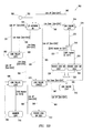
- FIG. 1 shows a block diagram of a network in accordance with at least some embodiments
- FIG. 1A shows aspects of the network of FIG. 1 in further detail
- FIG. 2 shows a block diagram of a network in accordance with at least some embodiments
- FIG. 3 shows a flowchart of a process in accordance with at least some embodiments
- FIG. 4 shows a block diagram of a portion of a network in accordance with at least some embodiments
- FIG. 5A shows a block diagram of a network in accordance with at least some embodiments
- FIG. 5B shows a state diagram of a portion of a state machine for controlling the configuration of the network of FIG. 5A ;
- FIG. 6 shows a flowchart of a process in accordance with at least some embodiments
- FIG. 7 shows a block diagram of a device in accordance with at least some embodiments.
- FIG. 8A shows a block diagram of a portion of a network in accordance with at least some embodiments.
- FIG. 8B shows another portion of the network of FIG. 8A .
- End-point node means a device that natively resides on a bus and produces or consumes data on the bus. End-point nodes include, but are not limited to, bus-native storage devices, bus-native input/output (I/O) devices and signal interface devices.
- I/O input/output
- Link means a full-duplex communication pathway of any width linking two root nodes and comprising one or more link segments.
- Link segment means a communication pathway that is a part of a link.
- Root node is a network node that includes logic and other circuitry for connecting a processor (CPU) to the network.
- CPU processor
- PCIe Peripheral Component Interconnect Express
- the logic and other circuitry for connecting the CPU to a PCIe network is referred to as a root complex.
- Service point device means a device that provides a network connection and interface between the network and a sensor.
- “Sensor” means an end-point device that produces or consumes data in an interface that is not native to the network.
- “Signal interface device” means a device that can be configured to connect to the network and provides an interface between a sensor and the network.
- a service point device may include a signal interface device.
- network 100 may be a Peripheral Component Interconnect Express (PCIe) network.
- PCIe is an industry-standard computer expansion bus.
- the PCIe specification is promulgated by the PCI-SIG, Beaverton, Oreg.
- Network 100 includes root nodes 1021 - 1023 , switches 104 A- 104 C connected to root nodes 1021 - 1023 , respectively and switches 1041 - 1049 connected by serial link segments as further described below.
- Root nodes 1021 - 1023 may include a processor (CPU) and, in the PCIe context, a root complex.
- End-point nodes 1061 - 1069 are coupled to respective ones of switches 1041 - 1049 .
- end-point nodes 1061 - 1069 may include storage devices and input/output (I/O) devices, but are not limited to such devices. Other end-point device embodiments are described below in conjunction with FIGS. 7 and 8 .
- each of switches 1041 - 1049 is shown with a single connected end-point node, 1061 - 1069 . It would be readily appreciated, that network 100 is not limited to such embodiments, and any of switches 1041 - 1049 may have multiple connected end-point nodes.
- a commercially available switch may be the PEX8714 device from PLX Technology, Inc., San Jose, Calif., includes five ports.
- a switch such a switch 1041 comprising a PEX8714 could support two additional end-point nodes, with one port connected to link 1051 and another to link 1052 .
- the PEX8714 device is an example of a switch that may be used in embodiments of network 100 and other switches with differing numbers of available ports also may be used embodiments in accordance with the disclosed principles.
- Switches 1041 and 1049 also are coupled by respective link segments 1051 and 1059 to switch 104 A.
- switches 1043 and 1044 are coupled by respective link segments 1053 and 1054 to switch 104 B and switches 1046 and 1047 are connected by respective link segments 1056 and 1057 to switch 104 C.
- a network link (or simply “link”) may comprise one or more link segments. Links may be single segment links or multi-segment links. A link comprising a single link segment may simply be referred to as a link, and such single segment links will be clear from the context. For example, single-segment link 1081 connects switches 104 A and 104 B. Similarly, link 1082 connects switches 104 B and 104 C and link 1083 couples switch 104 C and 104 A.
- Multi-segment link 1075 includes link segments 1051 , 1052 , 1055 and 1053 . Each link segment includes two ends, each end connected to a switch. For example, link segment 1051 has an end connected to switch 104 A and another end connected to switch 1041 . Similarly, link segment 1055 has an end connected to switch 1042 and another connected to switch 1043 . Likewise, multi-segment link 1076 includes link segments 1054 , 1058 , 1071 and 1056 ; and multi-segment link 1077 includes link segments 1057 , 1072 , 1073 and 1059 . Link segments convey electrical and/or data communication signals between network devices connected thereto.
- Links 1081 - 1083 may connect to a non-transparent port on one of the respective switches 104 A- 104 C.
- ports 111 A- 1110 in switches 104 A- 104 C, respectively, may be non-transparent.
- at least one of the ports connected to the link segments between in switches 1041 - 1043 , or between switches 1043 and 1048 may be non-transparent.
- at least one of the ports connected to the link segments between switches 1044 - 1046 , or between switches 1046 and 104 C, and at least one of the ports connected to link segments between switches 1047 - 1049 , or between switches 1049 and 104 A may be non-transparent.
- port 1116 in switch 1046 may be non-transparent.
- ports 1113 and 1119 in switches 1043 and 1049 may be non-transparent.
- a non-transparent port may comprise a non-transparent bridge in which transactions crossing the bridge are address-translated between address spaces assigned on each side of the bridge.
- root node 1021 will not enumerate devices connected to switches 104 B and 104 C.
- root node 1022 will not enumerate devices connected to switches 104 A and 104 C, and root node 1023 will not enumerate devices connected to switches 104 A and 104 B.
- a port that is initially set as a non-transparent port may be unset and a port initially in transparent mode may be reset in non-transparent mode. This will be described further below in conjunction with the mitigation of single-point failures.
- FIG. 1A illustrating in further detail the ring-based interconnects of network 100 .
- FIG. 1A shows a set of four ring interconnections (or simply “rings”) 1091 , 1092 , 1093 and 1094 , as traced by the bold lines shown in FIG. 1A .
- the bold lines are not intended to necessarily represent electrical or communication circuits, but to guide the eye in delineating the ring interconnections.
- link segments 1081 - 1083 may connect to a non-transparent port in switches 104 A- 104 C. The operation of the ring interconnections in mitigating single-point failures will be described below.
- Each ring interconnection in accordance with the principles disclosed herein may include two or more network nodes.
- rings 1091 - 1094 includes three or more network nodes, and each of the rings 1091 - 1094 includes at least two root nodes.
- ring 1094 includes three root nodes 1021 - 1023 .
- each of switches 104 A- 104 C connecting root nodes 1021 - 1023 , respectively, to the network provides three or more connections to the network.
- Each network device that is not a root node provides at least two connections to the network.
- each of switches 1041 - 1049 provides two connections to the network.
- Network 200 includes five rings 2091 - 2095 .
- the bold lines are to guide the eye in delineating the ring topology, and do not necessarily represent electrical or communication circuits.
- Network 200 includes root nodes 2021 - 2026 , coupled to the network via switches 204 A- 204 F, respectively. Similarly to link segments 1081 - 1083 in FIG.
- link 2081 for example, between switches 204 B and 204 D may connect to a non-transparent port on one of switches 204 B and 204 D, say port 211 D, to segregate root nodes 2022 and 2024 , and their respective end-point device domains, as described further below.
- each of rings 2091 - 2095 includes at least three root nodes, and each of the switches 204 A- 204 F associated with the respective root node provides at least three connections to the network.
- Network 200 also includes end-point nodes 2061 - 2066 connected to the network via switches 2041 - 2046 , respectively. Also similarly to network 100 , each of network switches 2014 - 2046 provides two connections to the network.
- each of root nodes 1021 - 1023 may be associated with a respective domain 1031 - 1033 .
- Root node 1021 may include a root complex for domain 1031 .
- root nodes 1022 and 1023 may include a root complex for domains 1032 and 1033 , respectively.
- each of root nodes 1021 - 1023 may enumerate the various devices on the network, or generate an address translation mapping if a device is connected to network 100 via a non-transparent port.
- link segments 1081 - 1083 between switches 104 A- 104 C may be connected via a non-transparent port in each one of the switches 104 A- 104 C.
- the root nodes, and their respective domains 1031 - 1033 may be segregated, and communication between the root nodes (and their respective domains) effected via an address mapping between the root nodes and also between the devices in each of the respective domains thereof.
- the view of each network device is as a memory space, although network devices, end-point nodes in particular, are not necessarily memory as such.
- the root node address space may be referred to as a mapped address space and the mapping of a network device into the mapped address space as device address mapping.
- Communication with the network device uses its mapped address. Stated otherwise, data may be sent to a network device by a write to its mapped address and received from a network device by a read from its mapped address as if the network device were memory, although a network device need not be limited to a memory device.
- Process 300 starts at block 302 and at block 304 a link connection is detected by a network device.
- the detecting network device notifies the nearest root node that it has connected to network, block 306 .
- the detection and notification may be effected via the hardware supporting the PCIe hot-plug capability within a PCIe switch.
- the root node notified in block 306 reads a network configuration file stored therein, block 308 .
- the network configuration file specifies the network connection topology at start-up.
- the network configuration file specifies the configuration, or layout of the network at start-up.
- the network configuration specifies the layout of the memory-mapped address space for each root node and the addresses assigned to each network device.
- the notified root node determines, based on the configuration file, if the notifying device is in the root node's address space. If so, process 300 proceeds by the “Y” branch of block 310 and enumerates the device, block 312 . In this way, the notifying device may then be informed of its address within the root node's address space. Otherwise, process 300 proceeds by the “N” branch of block 310 and, in block 314 , sets up a non-transparent address mapping between the root node's address space and the address space of the notifying device as specified in the configuration file.
- the network configuration may be static. That is, the network, once initialized in accordance with the configuration as set forth in the static configuration file, does not change architecturally, absent a single-point failure and recovery therefrom, as described further below. This prevents, for example, a new device from joining the network.
- a static configuration may be advantageous in a network employed in a system in which safety and/or security are paramount, such as a network that is part of an airborne or other vehicular electronics system.
- the configuration file may be digitally signed to prevent unauthorized modification of the configuration file.
- FIG. 4 showing a portion 400 of network 100 .
- Portion 400 is but for the illustrated SPF comprised of ring 1092 , FIG. 1A .
- the SPF is shown as a missing link segment to represent a link failure between switch 1045 and switch 1046 .
- root node 1022 may be the root node of switch 1046 and end-point node 1066 connected thereto.
- port 111 C in switch 104 C may be a non-transparent port.
- any communication between, say, root node 1022 and end-point device 1066 is routed through root node 1023 via link segment 1082 .
- SPF switch 1046 and any devices connected thereto such as end-point node 1066 , are isolated.
- SPF recovery in accordance with at least some embodiments, an exemplary network and associated state diagram for a state machine for controlling the network in response to link failures will be described in conjunction with FIGS. 5A and 5B .
- a process for recovering from the SPF will be described below in conjunction with FIG. 6 .
- Network 2200 includes root nodes 2221 , 2223 and 2224 .
- Each of root nodes 2221 , 2223 and 2224 may include one or more CPUs and, in a PCIe context, a root complex.
- Root nodes 2221 , 2223 and 2224 are connected to network 2200 via switches 221 A- 2210 , respectively.
- Network 2200 also comprises end-point nodes 2261 , 2262 and 2263 which are coupled to network 2200 via switches 2212 , 2213 and 2216 , respectively. Similar to network 100 , FIG. 1 , network 2200 incorporates ring interconnections.
- the ring interconnections include links 2231 , 2232 and 2234 .
- another ring interconnection includes link 2231 and link segments 2243 , 2242 and 2241
- still another ring interconnection comprises link 2234 and link segments 2244 and 2245 .
- Links 2231 and 2234 may be non-transparent links wherein a port, e.g. port 2250 in switch 221 A and port 2252 in switch 221 C is a non-transparent port. As described further below in conjunction with FIG.
- root node 2221 may comprise a root complex for a network chain including switches 221 A, 2212 and 2213 ; the end-point devices connected to switches 2212 and 2213 , 2261 and 2262 , respectively; and the link segments therebetween, link segment 2241 between switches 221 A and 2212 and link segment 2242 between switches 2212 and 2213 .
- root node 2221 may set up switch 2211 such that link segment 2241 is a transparent link segment on the root domain of root node 2221 .
- port 2251 on switch 2211 may be set up as transparent port.
- Root node 2221 may also set up switch 2212 such that the link segment 2242 is transparent wherein port 2253 is set as a transparent port.
- root node 2221 may set up switch 2213 such that link segment 2243 is non-transparent (NT) wherein port 2254 is set as a non-transparent port.
- NT non-transparent
- the system enters via path 552 , the “I/O Network OK” state 504 , where depending on Link Up/Down events the state machine transitions to other states.
- a “Link Down” event is caused when the hardware detects the link segment disconnection.
- a “Link Up” event is caused when the hardware detects a link segment that was previously disconnected becomes connected.
- hardware may detect link disconnections and connections by via the hardware supporting the PCIe hot-plug capability within a PCIe switch.
- Root node 2223 may then initiate a network reconfiguration and sets the link control for link segment 2243 in switch 2213 to be upstream and the link control for link segment 2242 in switch 2213 to be non-transparent. Stated otherwise, port 2254 is set to an upstream port, and port 2257 in switch 2213 is set to a non-transparent port. This allows for link segment 2242 to be reconnected without root node 2221 assuming control of device 2262 , while allowing root node 2223 to be the root complex for end-point node 2262 .
- the state machine transitions, at path 562 to the “Link Failure 2242 ( 2 )” state 514 .
- state machine 500 may not include a mechanism to handle a link segment 2241 failure because such a failure could not be handled if link segment 2243 is also disconnected, as devices 2261 and 2262 are then completely disconnected from the system.
- end-point node 2262 is hosted on root node 2221 , end-node 2262 is re-hosted on root node 2223 , via path 572 and “Rehost 2262 on 2223 ” state 520 .
- State machine 500 returns via join 522 and path 574 to “Link Failure 2241 ” state, 516 .
- state machine 500 proceeds via fork 518 and path 576 to “Rehost 2261 on 2223 ” state 524 .
- State machine 500 returns via join 522 and path 574 to “Link Failure 2241 ” state 516 .
- State machine 500 may include path 570 to account for the possibility that end-point node 2262 may have already been re-hosted on root node 2223 from root node 2221 .
- the re-hosting process starts by reconfiguration of the links involved, such that the root complex for that part of the network is transparent to the device and the non-transparent port is moved to isolate the rest of the downstream network.
- the devices are enumerated and the drivers for those devices may be loaded on the new host, or if the software may not be loaded, the address mapping becomes accessible to the software running on root node 2221 via the non-transparent link 2231 using a specific address mapping such that direct accesses to end-point node 2262 are routed from root node 2221 , through switch 221 A, link 2231 , switch 221 B, link segment 2243 , and switch 2213 , to end-point node 2262 .
- FIG. 6 illustrates a flow chart of a process 600 for SPF recovery in accordance with at least some embodiments.
- Process 600 starts at block 602 .
- a link segment disconnection is detected.
- a hotlink detection/disconnection notification may be through a hardware interrupt generated by a network switch.
- polling of the link state may be used to detect a link segment disconnection.
- the network device detecting the link segment disconnect a switch for example, notifies the closest connected root node of the link segment disconnect, block 606 .
- the notifying network device may be switch 1046 .
- the notified root node enumerates the switches on the link segments where the failure was reported, block 608 .
- non-transparent port 1116 may be unset, switch 1046 on link segment 1056 enumerated, and root node 1023 becomes the root node for switch 1046 and its end-point node 1066 .
- Blocks 604 - 606 are performed by each of the disconnected switches, illustrated by the loop in block 610 via the “N” branch thereof. Although blocks 604 - 608 are depicted serially for ease of illustration, they are not necessarily performed serially.
- Process 600 ends at block 612 upon completion of the actions by the disconnected switches, as depicted by the “Y” branch of block 610 .
- network devices may be deployed in an environment in which safety and/or security are issues, such as a network that is part of an airborne or other vehicular electronics system.
- safety and/or security are issues
- Such systems may include a multiplicity of electronic devices that generate data and signals that may then be aggregated and communicated to other devices that may, for example, process the data.
- the distribution of data within the system may be effected using network having a ring-based interconnect network with an SPF recovery mechanism in accordance with the principles described herein.
- a device, referred to herein as a service point device, that may be used in conjunction therewith to connect various electronic devices such as electronic devices in an airborne or vehicular electronics system will now be described in conjunction with FIG. 7 .
- FIG. 7 shows a service point device 700 in accordance with some embodiments.
- Service point device 700 includes a signal interface device 702 .
- signal interface device 702 may connect to one or more sensors and provide an interface to a network.
- Signal interface device 702 may connect to a network via a network device, such as switch 704 .
- switch 704 may be a PCIe switch in at least some embodiments of service point device 700 .
- Switch 704 may then provide the connection of service point device 700 to a network, such as ring-based interconnect network 100 , FIG. 1 .
- signal interface device may be an end-point node such as an end-point node 1061 - 1066 .
- Power to signal interface device 702 and switch 704 may be provided by a power supply 706 .
- FIGS. 8A and 8B show portions 800 A and 800 B, respectively of a network 800 in accordance with at least some embodiments.
- Network 800 may comprise a ring-based topology similar to the examples of FIGS. 1 and 2 .
- Network 800 includes service point devices 700 .
- a plurality of sensors 802 are coupled to respective ones of signal interface devices 702 in service point devices 700 .
- Power supplies 706 have been omitted in FIG. 7 for ease of illustration.
- Sensors 802 may be an end-point device that either creates or consumes data on an interface that is not network native.
- Examples include analog I/O devices such as analog instrumentation, digital I/O devices that are not network native, such as ARINC-429 bus devices, MIL-STD-1553 bus devices, Ethernet network interconnect cards (NIC), serial peripheral interface (SPI) devices, controller area network (CAN) devices, or radios and similar analog devices, or embedded processor systems without a network-native interface card and the like.
- analog I/O devices such as analog instrumentation, digital I/O devices that are not network native, such as ARINC-429 bus devices, MIL-STD-1553 bus devices, Ethernet network interconnect cards (NIC), serial peripheral interface (SPI) devices, controller area network (CAN) devices, or radios and similar analog devices, or embedded processor systems without a network-native interface card and the like.
- NIC Ethernet network interconnect cards
- SPI serial peripheral interface
- CAN controller area network
- radios and similar analog devices or embedded processor systems without a network-native interface card and the like.
- two sensors 802 are shown coupled to each of signal interface devices 702
- RAM 812 A may be included and coupled to CPU 810 A to provide programming instructions to CPU 810 A.
- programming instructions stored in RAM 812 A may be executed by CPU 810 A to perform actions in conjunction with processes 300 and 600 described above in conjunction with FIGS. 3 and 6 , respectively.
- RAM 812 A may be comprised, at least in part, of non-volatile memory, such as flash memory. However, any suitable memory technology may be used.
- switch 806 A may be connected via port 8111 to a switch 8061 .
- An end-point node 8121 may also be connected to switch 8061 and switch 8061 further connected to switch 8062 .
- End-point node 8121 and end-point node 8122 connected to switch 8062 may comprise service point devices, but either additionally or alternatively might comprise other end-point devices also.
- Switch 8062 may also be coupled to switch 806 B and thereby to root node 808 B.
- Switch 806 B may be connected to a second port, port 811 A on switch 806 A in accordance with the ring-based topology principles described herein. In this way, SPF mitigation may be provided as set forth hereinabove in conjunction with FIGS. 1-6 .
- Switch 806 B may be coupled to a root node 808 B which may also comprise a CPU, CPU 810 B. Root node 808 B may also include RAM 812 B. Similar to RAM 812 A, RAM 812 B may be coupled to and provide programming instructions to CPU 810 B, including programming instructions for performing actions in conjunction with processes 300 and 600 .
Abstract
Description
Claims (4)
Priority Applications (3)
| Application Number | Priority Date | Filing Date | Title |
|---|---|---|---|
| US14/567,143 US9800461B2 (en) | 2014-12-11 | 2014-12-11 | Ring-based network interconnect |
| PCT/US2015/064736 WO2016094529A1 (en) | 2014-12-11 | 2015-12-09 | Ring-based network interconnect |
| US15/648,217 US10673693B2 (en) | 2014-12-11 | 2017-07-12 | Ring based network interconnect |
Applications Claiming Priority (1)
| Application Number | Priority Date | Filing Date | Title |
|---|---|---|---|
| US14/567,143 US9800461B2 (en) | 2014-12-11 | 2014-12-11 | Ring-based network interconnect |
Related Child Applications (1)
| Application Number | Title | Priority Date | Filing Date |
|---|---|---|---|
| US15/648,217 Continuation US10673693B2 (en) | 2014-12-11 | 2017-07-12 | Ring based network interconnect |
Publications (2)
| Publication Number | Publication Date |
|---|---|
| US20160173325A1 US20160173325A1 (en) | 2016-06-16 |
| US9800461B2 true US9800461B2 (en) | 2017-10-24 |
Family
ID=56108113
Family Applications (2)
| Application Number | Title | Priority Date | Filing Date |
|---|---|---|---|
| US14/567,143 Active 2035-03-19 US9800461B2 (en) | 2014-12-11 | 2014-12-11 | Ring-based network interconnect |
| US15/648,217 Active 2035-01-14 US10673693B2 (en) | 2014-12-11 | 2017-07-12 | Ring based network interconnect |
Family Applications After (1)
| Application Number | Title | Priority Date | Filing Date |
|---|---|---|---|
| US15/648,217 Active 2035-01-14 US10673693B2 (en) | 2014-12-11 | 2017-07-12 | Ring based network interconnect |
Country Status (2)
| Country | Link |
|---|---|
| US (2) | US9800461B2 (en) |
| WO (1) | WO2016094529A1 (en) |
Families Citing this family (7)
| Publication number | Priority date | Publication date | Assignee | Title |
|---|---|---|---|---|
| US20170364687A1 (en) * | 2016-06-18 | 2017-12-21 | Lior Malka | Sealed network initialization |
| CN111030911B (en) * | 2018-10-09 | 2022-04-22 | 中车株洲电力机车研究所有限公司 | Train network system and terminal equipment access management method for train network system |
| US11038749B2 (en) * | 2018-12-24 | 2021-06-15 | Intel Corporation | Memory resource allocation in an end-point device |
| US11729184B2 (en) | 2019-05-28 | 2023-08-15 | Rankin Labs, Llc | Detecting covertly stored payloads of data within a network |
| US11516048B2 (en) * | 2019-12-18 | 2022-11-29 | Rankin Labs, Llc | Distribution of data over a network with interconnected rings |
| US11652663B1 (en) | 2022-01-28 | 2023-05-16 | Honeywell International Inc. | Controller area network braided ring |
| CN116028430B (en) * | 2023-03-28 | 2023-06-13 | 飞腾信息技术有限公司 | Scanning method of pcie equipment and system-on-chip |
Citations (19)
| Publication number | Priority date | Publication date | Assignee | Title |
|---|---|---|---|---|
| US20020169960A1 (en) | 2001-02-07 | 2002-11-14 | Shinya Iguchi | Storage device including a non-volatile memory |
| US6839792B2 (en) | 2000-12-15 | 2005-01-04 | Innovative Concepts, Inc. | Data modem |
| US20060230217A1 (en) | 2003-05-15 | 2006-10-12 | Moll Laurent R | Peripheral bus switch having virtual peripheral bus and configurable host bridge |
| US20080240134A1 (en) | 2007-03-30 | 2008-10-02 | International Business Machines Corporation | Multi-node, peripheral component switch for a computer system |
| US20090022317A1 (en) | 2007-07-20 | 2009-01-22 | Seiko Epson Corporation | Vehicle security system |
| US7783818B1 (en) * | 2007-12-28 | 2010-08-24 | Emc Corporation | Modularized interconnect between root complexes and I/O modules |
| US20110112969A1 (en) | 2009-10-30 | 2011-05-12 | Gettaround, Inc. | Vehicle access control services and platform |
| US20120180507A1 (en) | 2005-12-16 | 2012-07-19 | Eric Leebow | Computer interface system |
| US20120303177A1 (en) | 2009-12-03 | 2012-11-29 | Continental Automotive Gmbh | Docking terminal and system for controlling vehicle functions |
| WO2013103519A1 (en) | 2012-01-06 | 2013-07-11 | Ge Intelligent Platforms, Inc. | Extensible daisy-chain topology for compute devices |
| US20130179622A1 (en) * | 2012-01-06 | 2013-07-11 | Gary L. Pratt | System and method for transmitting and receiving data using an industrial expansion bus |
| US20130179722A1 (en) | 2012-01-06 | 2013-07-11 | Glen Smith | Ring topology for compute devices |
| US20130227193A1 (en) | 2009-11-05 | 2013-08-29 | Rj Intellectual Properties, Llc | Unified System Area Network And Switch |
| US20140195108A1 (en) | 2013-01-07 | 2014-07-10 | Service Solutions U.S. Llc | Telecommunication Device Configured to Forward Vehicle Information from a Mobile Vehicle Monitoring Device |
| US20140237156A1 (en) * | 2012-10-25 | 2014-08-21 | Plx Technology, Inc. | Multi-path id routing in a pcie express fabric environment |
| US8904556B1 (en) | 2012-08-29 | 2014-12-02 | Rockwell Collins, Inc. | Multi-level security display with secure input/output |
| EP2808204A1 (en) | 2012-01-25 | 2014-12-03 | Toyota Jidosha Kabushiki Kaisha | Vehicle remote operation information provision device, vehicle-mounted remote operation information acquisition device, and vehicle remote operation system comprising these devices |
| US20160154756A1 (en) * | 2014-03-31 | 2016-06-02 | Avago Technologies General Ip (Singapore) Pte. Ltd | Unordered multi-path routing in a pcie express fabric environment |
| US9361249B2 (en) * | 2010-03-11 | 2016-06-07 | Ricoh Company, Ltd. | Communication apparatus, communication system and adapter |
Family Cites Families (4)
| Publication number | Priority date | Publication date | Assignee | Title |
|---|---|---|---|---|
| CN102285421B (en) | 2011-07-25 | 2013-06-05 | 大行科技(深圳)有限公司 | Grip of bicycle |
| US8683105B1 (en) * | 2011-09-02 | 2014-03-25 | Rockwell Collins, Inc. | Modular avionics system |
| US10649948B2 (en) * | 2011-10-05 | 2020-05-12 | Analog Devices, Inc. | Two-wire communication systems and applications |
| KR102007368B1 (en) * | 2012-12-17 | 2019-08-05 | 한국전자통신연구원 | PCI express switch and computer system using the same |
-
2014
- 2014-12-11 US US14/567,143 patent/US9800461B2/en active Active
-
2015
- 2015-12-09 WO PCT/US2015/064736 patent/WO2016094529A1/en active Application Filing
-
2017
- 2017-07-12 US US15/648,217 patent/US10673693B2/en active Active
Patent Citations (22)
| Publication number | Priority date | Publication date | Assignee | Title |
|---|---|---|---|---|
| US6839792B2 (en) | 2000-12-15 | 2005-01-04 | Innovative Concepts, Inc. | Data modem |
| US7167945B2 (en) | 2000-12-15 | 2007-01-23 | Feldstein Andy A | Data modem |
| US7293128B2 (en) | 2000-12-15 | 2007-11-06 | Innovative Concepts, Inc. | Data modem |
| US7296165B2 (en) | 2000-12-15 | 2007-11-13 | Innovative Concepts, Inc. | Method for power down interrupt in a data modem |
| US20020169960A1 (en) | 2001-02-07 | 2002-11-14 | Shinya Iguchi | Storage device including a non-volatile memory |
| US20060230217A1 (en) | 2003-05-15 | 2006-10-12 | Moll Laurent R | Peripheral bus switch having virtual peripheral bus and configurable host bridge |
| US20120180507A1 (en) | 2005-12-16 | 2012-07-19 | Eric Leebow | Computer interface system |
| US20080240134A1 (en) | 2007-03-30 | 2008-10-02 | International Business Machines Corporation | Multi-node, peripheral component switch for a computer system |
| US20090022317A1 (en) | 2007-07-20 | 2009-01-22 | Seiko Epson Corporation | Vehicle security system |
| US7783818B1 (en) * | 2007-12-28 | 2010-08-24 | Emc Corporation | Modularized interconnect between root complexes and I/O modules |
| US20110112969A1 (en) | 2009-10-30 | 2011-05-12 | Gettaround, Inc. | Vehicle access control services and platform |
| US20130227193A1 (en) | 2009-11-05 | 2013-08-29 | Rj Intellectual Properties, Llc | Unified System Area Network And Switch |
| US20120303177A1 (en) | 2009-12-03 | 2012-11-29 | Continental Automotive Gmbh | Docking terminal and system for controlling vehicle functions |
| US9361249B2 (en) * | 2010-03-11 | 2016-06-07 | Ricoh Company, Ltd. | Communication apparatus, communication system and adapter |
| US20130179622A1 (en) * | 2012-01-06 | 2013-07-11 | Gary L. Pratt | System and method for transmitting and receiving data using an industrial expansion bus |
| US20130179722A1 (en) | 2012-01-06 | 2013-07-11 | Glen Smith | Ring topology for compute devices |
| WO2013103519A1 (en) | 2012-01-06 | 2013-07-11 | Ge Intelligent Platforms, Inc. | Extensible daisy-chain topology for compute devices |
| EP2808204A1 (en) | 2012-01-25 | 2014-12-03 | Toyota Jidosha Kabushiki Kaisha | Vehicle remote operation information provision device, vehicle-mounted remote operation information acquisition device, and vehicle remote operation system comprising these devices |
| US8904556B1 (en) | 2012-08-29 | 2014-12-02 | Rockwell Collins, Inc. | Multi-level security display with secure input/output |
| US20140237156A1 (en) * | 2012-10-25 | 2014-08-21 | Plx Technology, Inc. | Multi-path id routing in a pcie express fabric environment |
| US20140195108A1 (en) | 2013-01-07 | 2014-07-10 | Service Solutions U.S. Llc | Telecommunication Device Configured to Forward Vehicle Information from a Mobile Vehicle Monitoring Device |
| US20160154756A1 (en) * | 2014-03-31 | 2016-06-02 | Avago Technologies General Ip (Singapore) Pte. Ltd | Unordered multi-path routing in a pcie express fabric environment |
Non-Patent Citations (11)
| Title |
|---|
| Budruk, Ravi et al., PCI Express System Architecture, MindShare, Inc., 2003, 222 pages. |
| Conley, Reginald, PCIe Goes ‘Clock-less’, PLX Technology, Independent SSC Operation without SSC Clock Isolation, White Paper, May 11, 2012, 9 pages. |
| Conley, Reginald, PCIe Goes 'Clock-less', PLX Technology, Independent SSC Operation without SSC Clock Isolation, White Paper, May 11, 2012, 9 pages. |
| Dolphin Interconnect Solutions, Dolphin Express IX Reflective Memory/Multicast, Whitepaper, Jun. 19, 2013, 8 pages. |
| Integrated Device Technology, PCI Express(r) Solutions, Product Overview, Aug. 14, 2014, 4 pages. |
| PCI Express System Architecture, Chapter 3, Address Spaces & Transaction Routing, Aug. 5, 2003, pp. 105-152. |
| PCI-Express AceXtreme(r) Data Sheet, Model BU-67302B0C0L-202, Data Device Corporation, 2012, (62 pages). |
| PCT Application No. PCT/US2015/064736 Search Report and Written Opinion dated Apr. 18, 2016. |
| PLX Technology and Avago Technologies, A Demonstration of PCI Express Generation 3 over a Fiber Optical Link, White Paper, Nov. 15, 2011, 9 pages. |
| PLX Technology, Product Brief, PEX 8717, PCI Express Gen 3 Switch, 16 Lanes, 10 Ports, Aug. 1, 2011, 5 pages. |
| PLX Technology, Product Brief, PEX8714, PCI Express Gen3 Switch, 12 Lanes, 5 Ports, Sep. 10, 2012, 4 pages. |
Also Published As
| Publication number | Publication date |
|---|---|
| WO2016094529A1 (en) | 2016-06-16 |
| US10673693B2 (en) | 2020-06-02 |
| US20160173325A1 (en) | 2016-06-16 |
| US20170310544A1 (en) | 2017-10-26 |
Similar Documents
| Publication | Publication Date | Title |
|---|---|---|
| US10673693B2 (en) | Ring based network interconnect | |
| JP7118922B2 (en) | Switching device, peripheral component interconnect express system and its initialization method | |
| US9030943B2 (en) | Recovering from failures without impact on data traffic in a shared bus architecture | |
| US11132323B2 (en) | System, apparatus and method for extended communication modes for a multi-drop interconnect | |
| US11372790B2 (en) | Redundancy in a PCI express system | |
| CN1909559B (en) | Interface board based on rapid periphery components interconnection and method for switching main-control board | |
| JP2005141739A (en) | Dynamic reconfiguration of pci express link | |
| US9864605B2 (en) | Multistage boot image loading by configuration of a bus interface | |
| JP2007219873A (en) | Switch and network bridge device | |
| US10432557B2 (en) | Network device | |
| US20160267035A1 (en) | Methods and apparatus for augmented bus numbering | |
| US8775712B2 (en) | Bus connecting device for connecting host with external device | |
| US20120131188A1 (en) | Network concentrator and method of controlling the same | |
| US7206889B2 (en) | Systems and methods for enabling communications among devices in a multi-cache line size environment and disabling communications among devices of incompatible cache line sizes | |
| JP6155500B2 (en) | Relay device | |
| CA2434899C (en) | Fault tolerance | |
| JP6357879B2 (en) | System and fault handling method | |
| US11797468B2 (en) | Peripheral component interconnect express device and computing system including the same | |
| US20220382705A1 (en) | Peripheral component interconnect express device and operating method thereof | |
| JP3410002B2 (en) | Communication control integrated circuit and communication control system | |
| WO2020232582A1 (en) | Integrated circuit having interface multiplexing functionality and pin switching method | |
| US20230421432A1 (en) | Communication apparatus and communication system | |
| US11921657B2 (en) | Peripheral component interconnect express (PCIE) device for supporting separate reference clock(s) operating between host and direct memory access (DMA) controller | |
| KR102144791B1 (en) | Apparatus and method of detecting error of serial communication lines | |
| US20240012770A1 (en) | Interface device having plurality of ports and method of operating the same |
Legal Events
| Date | Code | Title | Description |
|---|---|---|---|
| AS | Assignment |
Owner name: ELBIT SYSTEMS OF AMERICA, LLC, TEXAS Free format text: ASSIGNMENT OF ASSIGNORS INTEREST;ASSIGNORS:WOODWARD, ROBERT A.;HERRING, DANIEL M.;HULL, ANDREW W.;REEL/FRAME:034573/0709 Effective date: 20141212 |
|
| AS | Assignment |
Owner name: WELLS FARGO BANK, NATIONAL ASSOCIATION, AS COLLATERAL AGENT, TEXAS Free format text: SECURITY INTEREST;ASSIGNORS:ELBIT SYSTEMS OF AMERICA, LLC;KMC SYSTEMS, INC.;REEL/FRAME:043439/0953 Effective date: 20170828 Owner name: WELLS FARGO BANK, NATIONAL ASSOCIATION, AS COLLATE Free format text: SECURITY INTEREST;ASSIGNORS:ELBIT SYSTEMS OF AMERICA, LLC;KMC SYSTEMS, INC.;REEL/FRAME:043439/0953 Effective date: 20170828 |
|
| STCF | Information on status: patent grant |
Free format text: PATENTED CASE |
|
| AS | Assignment |
Owner name: WELLS FARGO BANK, NATIONAL ASSOCIATION, TEXAS Free format text: SECURITY INTEREST;ASSIGNOR:ELBIT SYSTEMS OF AMERICA, LLC;REEL/FRAME:050375/0425 Effective date: 20190913 |
|
| MAFP | Maintenance fee payment |
Free format text: PAYMENT OF MAINTENANCE FEE, 4TH YEAR, LARGE ENTITY (ORIGINAL EVENT CODE: M1551); ENTITY STATUS OF PATENT OWNER: LARGE ENTITY Year of fee payment: 4 |
|
| AS | Assignment |
Owner name: CAPITAL ONE, NATIONAL ASSOCIATION, AS AGENT, ILLINOIS Free format text: SECURITY INTEREST;ASSIGNORS:ELBIT SYSTEMS OF AMERICA, LLC;SPARTON CORPORATION;SPARTON DELEON SPRINGS, LLC;AND OTHERS;REEL/FRAME:066642/0935 Effective date: 20240221 Owner name: ELBIT SYSTEMS OF AMERICA, LLC, TEXAS Free format text: RELEASE BY SECURED PARTY;ASSIGNOR:WELLS FARGO BANK, NATIONAL ASSOCIATION;REEL/FRAME:066644/0612 Effective date: 20240221 |