US9799377B1 - Gas-charging head with integral valves - Google Patents
Gas-charging head with integral valves Download PDFInfo
- Publication number
- US9799377B1 US9799377B1 US14/739,286 US201514739286A US9799377B1 US 9799377 B1 US9799377 B1 US 9799377B1 US 201514739286 A US201514739286 A US 201514739286A US 9799377 B1 US9799377 B1 US 9799377B1
- Authority
- US
- United States
- Prior art keywords
- gas
- valve
- channel
- charging head
- channels
- Prior art date
- Legal status (The legal status is an assumption and is not a legal conclusion. Google has not performed a legal analysis and makes no representation as to the accuracy of the status listed.)
- Active, expires
Links
- 238000004891 communication Methods 0.000 claims abstract description 28
- 238000007789 sealing Methods 0.000 claims description 7
- 238000013500 data storage Methods 0.000 claims description 5
- 238000005070 sampling Methods 0.000 claims description 4
- 239000007789 gas Substances 0.000 abstract description 60
- 239000001307 helium Substances 0.000 abstract description 17
- 229910052734 helium Inorganic materials 0.000 abstract description 17
- SWQJXJOGLNCZEY-UHFFFAOYSA-N helium atom Chemical compound [He] SWQJXJOGLNCZEY-UHFFFAOYSA-N 0.000 abstract description 17
- 238000000034 method Methods 0.000 abstract description 9
- 238000003860 storage Methods 0.000 description 7
- IJGRMHOSHXDMSA-UHFFFAOYSA-N Atomic nitrogen Chemical compound N#N IJGRMHOSHXDMSA-UHFFFAOYSA-N 0.000 description 6
- 238000010926 purge Methods 0.000 description 6
- 230000006835 compression Effects 0.000 description 4
- 238000007906 compression Methods 0.000 description 4
- 239000000203 mixture Substances 0.000 description 3
- 229910052757 nitrogen Inorganic materials 0.000 description 3
- 238000010586 diagram Methods 0.000 description 2
- 230000007246 mechanism Effects 0.000 description 2
- 230000008569 process Effects 0.000 description 2
- UFHFLCQGNIYNRP-UHFFFAOYSA-N Hydrogen Chemical compound [H][H] UFHFLCQGNIYNRP-UHFFFAOYSA-N 0.000 description 1
- 230000008878 coupling Effects 0.000 description 1
- 238000010168 coupling process Methods 0.000 description 1
- 238000005859 coupling reaction Methods 0.000 description 1
- 230000001066 destructive effect Effects 0.000 description 1
- 238000005553 drilling Methods 0.000 description 1
- 230000009977 dual effect Effects 0.000 description 1
- 239000001257 hydrogen Substances 0.000 description 1
- 229910052739 hydrogen Inorganic materials 0.000 description 1
- 238000004519 manufacturing process Methods 0.000 description 1
- 230000000116 mitigating effect Effects 0.000 description 1
- 238000012986 modification Methods 0.000 description 1
- 230000004048 modification Effects 0.000 description 1
- 238000012544 monitoring process Methods 0.000 description 1
- 230000009467 reduction Effects 0.000 description 1
- 238000006467 substitution reaction Methods 0.000 description 1
- 238000012360 testing method Methods 0.000 description 1
Images


Classifications
-
- G—PHYSICS
- G11—INFORMATION STORAGE
- G11B—INFORMATION STORAGE BASED ON RELATIVE MOVEMENT BETWEEN RECORD CARRIER AND TRANSDUCER
- G11B33/00—Constructional parts, details or accessories not provided for in the other groups of this subclass
- G11B33/14—Reducing influence of physical parameters, e.g. temperature change, moisture, dust
- G11B33/1486—Control/regulation of the pressure, e.g. the pressure inside the housing of a drive
-
- F—MECHANICAL ENGINEERING; LIGHTING; HEATING; WEAPONS; BLASTING
- F17—STORING OR DISTRIBUTING GASES OR LIQUIDS
- F17C—VESSELS FOR CONTAINING OR STORING COMPRESSED, LIQUEFIED OR SOLIDIFIED GASES; FIXED-CAPACITY GAS-HOLDERS; FILLING VESSELS WITH, OR DISCHARGING FROM VESSELS, COMPRESSED, LIQUEFIED, OR SOLIDIFIED GASES
- F17C13/00—Details of vessels or of the filling or discharging of vessels
- F17C13/02—Special adaptations of indicating, measuring, or monitoring equipment
-
- F—MECHANICAL ENGINEERING; LIGHTING; HEATING; WEAPONS; BLASTING
- F17—STORING OR DISTRIBUTING GASES OR LIQUIDS
- F17C—VESSELS FOR CONTAINING OR STORING COMPRESSED, LIQUEFIED OR SOLIDIFIED GASES; FIXED-CAPACITY GAS-HOLDERS; FILLING VESSELS WITH, OR DISCHARGING FROM VESSELS, COMPRESSED, LIQUEFIED, OR SOLIDIFIED GASES
- F17C13/00—Details of vessels or of the filling or discharging of vessels
- F17C13/04—Arrangement or mounting of valves
-
- F—MECHANICAL ENGINEERING; LIGHTING; HEATING; WEAPONS; BLASTING
- F17—STORING OR DISTRIBUTING GASES OR LIQUIDS
- F17C—VESSELS FOR CONTAINING OR STORING COMPRESSED, LIQUEFIED OR SOLIDIFIED GASES; FIXED-CAPACITY GAS-HOLDERS; FILLING VESSELS WITH, OR DISCHARGING FROM VESSELS, COMPRESSED, LIQUEFIED, OR SOLIDIFIED GASES
- F17C5/00—Methods or apparatus for filling containers with liquefied, solidified, or compressed gases under pressures
- F17C5/06—Methods or apparatus for filling containers with liquefied, solidified, or compressed gases under pressures for filling with compressed gases
-
- G—PHYSICS
- G11—INFORMATION STORAGE
- G11B—INFORMATION STORAGE BASED ON RELATIVE MOVEMENT BETWEEN RECORD CARRIER AND TRANSDUCER
- G11B33/00—Constructional parts, details or accessories not provided for in the other groups of this subclass
- G11B33/14—Reducing influence of physical parameters, e.g. temperature change, moisture, dust
- G11B33/148—Reducing friction, adhesion, drag
-
- F—MECHANICAL ENGINEERING; LIGHTING; HEATING; WEAPONS; BLASTING
- F17—STORING OR DISTRIBUTING GASES OR LIQUIDS
- F17C—VESSELS FOR CONTAINING OR STORING COMPRESSED, LIQUEFIED OR SOLIDIFIED GASES; FIXED-CAPACITY GAS-HOLDERS; FILLING VESSELS WITH, OR DISCHARGING FROM VESSELS, COMPRESSED, LIQUEFIED, OR SOLIDIFIED GASES
- F17C2260/00—Purposes of gas storage and gas handling
- F17C2260/04—Reducing risks and environmental impact
- F17C2260/044—Avoiding pollution or contamination
Definitions
- HDDs hard-disk drives
- AD is a measure of the amount of information that can be stored in a unit of area of the information-storage medium used to store information in the information-storage device, for example, an HDD.
- FIG. 1A is a perspective view of a gas-charging head, in one or more embodiments described herein;
- FIG. 1B is an exploded perspective view of the gas-charging head showing its component parts, in one or more embodiments described herein;
- FIG. 1C is an enlarged perspective view of the gas-charging head showing a third valve mounted directly on a body of the gas-charging head, in one or more alternative embodiments described herein;
- FIG. 1D is an enlarged perspective view of the gas-charging head showing an arrangement of channels communicating with a first valve, in one or more embodiments described herein;
- FIG. 1E is an enlarged perspective view of the gas-charging head showing an arrangement of channels communicating with a second valve, in one or more embodiments described herein;
- FIG. 1F is an enlarged perspective view of the gas-charging head showing an arrangement of channels communicating with a third valve, in one or more embodiments described herein;
- FIG. 1G is an enlarged perspective view of the gas-charging head showing an arrangement of channels communicating with a fourth valve, in one or more embodiments described herein;
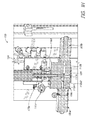
- FIG. 1H is an enlarged perspective cross-sectional view of the gas-charging head showing dual channels and a single channel communicating with a central channel and respective first and second valves, in one or more embodiments described herein;
- FIG. 2 is a schematic diagram of a system in which the gas-charging head is incorporated, in one or more embodiments described herein;
- FIG. 3 is a flow chart of a method of using the gas-charging head to charge a device with a quantity of gas, in one or more embodiments described herein.
- a perspective view of a gas-charging head 100 is shown.
- the gas-charging head 100 was developed by the inventor to provide an economical and efficient means for charging the interior space of a device, by way of example without limitation thereto, a data storage device such as a hard disk drive (HDD) or solid-state hybrid drive (SSHD), with a gas, such as helium, hydrogen and/or nitrogen, without limitation thereto.
- a data storage device such as a hard disk drive (HDD) or solid-state hybrid drive (SSHD)
- SSHD solid-state hybrid drive
- An HDD filled with helium, or alternatively another gas having molecular weight less than that of air, allows a reduction of fly height of a magnetic-recording head over a surface of a magnetic-recording disk in writing and/or reading operations to or from the disk that results in an increased areal density (AD) of information stored therein.
- AD areal density
- utility may be found in one or more of the following, without limitation thereto: reducing the consumption of expensive helium gas in filling the interior space of the HDD, mitigating the release of helium to the surrounding manufacturing environment that is monitored for leakage of trace amounts of helium from sealed HDDs, and/or increasing the speed with which HDDs can be charged with helium using an automated system and method, as for example shown in FIGS. 2 and 3 , respectively.
- FIG. 1B an exploded perspective view of the gas-charging head 100 detailing its component parts is shown.
- a plurality of valves by way of example without limitation thereto, valves 108 a , 108 b , 108 c and 108 d , are shown integrated in the gas-charging head 100 , which eliminates a corresponding plurality of dedicated valve manifolds and tubulation for gas-flow from dedicated valve manifolds to a body, which is substantially different from body 104 a of one or more embodiments described herein and shown in FIGS. 1A and 1B .
- the gas-charging head 100 includes the body 104 a and at least one valve, by way of example without limitation thereto, valve 108 a , 108 b , 108 c and/or 108 d , mounted on the body 104 a .
- valve 108 a , 108 b , 108 c and/or 108 d mounted on the body 104 a .
- the body 104 a has a plurality of channels, by way of example without limitation thereto, channels 112 a 1 , 112 a 2 , 112 b , 112 c 1 , 112 c 2 , 112 d , 112 e , 114 a , 114 b 1 , 114 b 2 , 114 c , 114 d 1 and 114 d 2 .
- the plurality of channels may be understood to refer to the set of channels 112 a 1 , 112 a 2 , 112 b , 112 c 1 , 112 c 2 , 112 d , 112 e , 114 a , 114 b 1 , 114 b 2 , 114 c , 114 d 1 and 114 d 2 , by way of example without limitation thereto.
- the plurality of channels is operable to communicate with an interior space of the device, which further eliminates a corresponding plurality of dedicated valve manifolds and tubulation for gas-flow from dedicated valve manifolds to a body, and also conserves the use of expensive helium gas in filling the interior space of the device, for example, an HDD.
- channel 112 a 1 , 112 a 2 , 112 b , 112 c 1 , 112 c 2 , 112 d , 112 e , 114 a , 114 b 1 , 114 b 2 , 114 c , 114 d 1 and/or 114 d 2 is operable to permit a flow of gas therethrough.
- At least one valve may be mounted on the body 104 a in communication with the channel, by way of example without limitation thereto, respective channel 112 a 1 , 112 a 2 , 112 b , 112 c 1 , 112 c 2 , 112 d , 112 e , 114 a , 114 b 1 , 114 b 2 , 114 c , 114 d 1 and/or 114 d 2 , of the plurality of channels.
- the body 104 a and a portion of the channel by way of example without limitation thereto, channel 112 a 1 , 112 a 2 , 112 b , 112 c 1 , 112 c 2 , 112 d , 112 e , 114 a , 114 b 1 , 114 b 2 , 114 c , 114 d 1 and/or 114 d 2 , are operable as a valve manifold for the valve, by way of example without limitation thereto, one of respective valves 108 a , 108 b , 108 c and/or 108 d.
- the body 104 a that includes the plurality of channels is operable to permit the flow of gas therethrough to the device, or in the alternative, from the device.
- a volume of the plurality of channels is less than a volume of a corresponding plurality of dedicated valve manifolds and tubulation for a gas-flow that the plurality of channels is operable to supply, which conserves the use of expensive helium gas in filling the interior space of the device, for example, an HDD.
- a plurality of valves is mounted on the body 104 a , the valve may be a first valve 108 a of the plurality of valves.
- the plurality of valves may be understood to refer to the set of valves 108 a , 108 b , 108 c and 108 d , by way of example without limitation thereto.
- the first valve 108 a of the plurality of valves is operable to communicate with a vacuum line 116 a .
- the valve may be a second valve 108 b of the plurality of valves that is mounted on the body 104 a .
- the second valve 108 b of the plurality of valves is operable to communicate with a gas-supply line 116 b .
- the gas-supply line 116 b is operable to supply a gas having molecular weight less than that of air to charge the device.
- the gas may be selected from the group of gases consisting of helium, nitrogen, and any mixture of helium and nitrogen, without limitation thereto.
- a third valve 108 c is in communication with a third channel, by way of example without limitation thereto, channel 112 c 1 , 112 c 2 and/or 114 c , of the plurality of channels and is operable to communicate with a gas-concentration sensor 110 .
- the third valve 108 c may be connected to the third channel, by way of example without limitations thereto, channel 112 c 1 , 112 c 2 and/or 114 c , in the body 104 a via a gas-sampling line (not shown). As shown in FIGS.
- the third valve 108 c and the gas-concentration sensor 110 are mounted on a separate concentration-sensing body 104 b , without limitation thereto, as the third valve 108 c and/or the gas-concentration sensor 110 may, in the alternative, be mounted on body 104 a (see, for example, FIG. 1C ).
- the valve may be a fourth valve 108 d of the plurality of valves that is mounted on the body 104 a that is operable to communicate with a purge-gas-supply line 116 d.
- the gas-charging head 100 may further include other components, such as a pressure transducer 120 in communication with the plurality of channels, which are subsequently described in the course of the following further description of the gas-charging head 100 .
- the body 104 a provides for communication between channels of the plurality of channels in delivering gas to the device.
- first channels 112 a 1 and 112 a 2 , second channel 112 b , third channels 112 c 1 and 112 c 2 , and fourth channel 112 d communicate directly with a central fifth channel 112 e that communicates directly with a charging port of the device, for example, an HDD.
- first channel 114 a , second channels 114 b 1 and 114 b 2 , third channel 114 c , and fourth channels 114 d 1 and 114 d 2 communicate directly with respective vertical riser channels.
- the vertical riser channels in turn communicate with respective connection elbows 118 a , 118 b and 118 d , except for elbow 118 c that communicates with channels in the separate concentration-sensing body 104 b , as the separate concentration-sensing body 104 b occupies the position that elbow 118 c would otherwise occupy to communicate with a respective vertical riser channel in body 104 a .
- Elbows 118 a , 118 b , 118 c and 118 d are provided with couplings that allow them to communicate with respective lines 116 a , 116 b , 116 c and 116 d , viz.: vacuum line 116 a , gas-supply line 116 b , low-pressure line 116 c , and purge-gas-supply line 116 d .
- the pressure transducer 120 also communicates with the central fifth channel 112 e through a respective vertical riser channel and a sixth channel (not shown).
- the pressure transducer 120 is operable to be in continuous communication with the interior space of the device through the sixth channel in communication with the fifth channel 112 e for monitoring the pressure within the interior space of the device to control operations of the plurality of valves affecting the pressure therein throughout the operation of the gas-charging head 100 , when in compliant contact with the charging port of the device.
- plug 140 seals the opening of the sixth channel, which may be fabricated by drilling, as may other of the channels be fabricated, into the body 104 a to join the respective vertical riser channel of the pressure transducer 120 with the central fifth channel 112 e.
- the central fifth channel 112 e is designed to accommodate a sealing tool 128 (see, for example FIG. 1H ) for opening and/or closing a charging port seal of the charging port of the device.
- the charging port seal may include a sticky label; in another embodiment, the charging port seal may include a charging port screw, without limitation to either.
- the sealing tool 128 may include a shaft portion disposed in the center of the central fifth channel 112 e by sleeve 132 d .
- the shaft portion of the sealing tool 128 is sealed in the central fifth channel 112 e by an upper O-ring 132 c and a lower O-ring 132 e disposed above and below sleeve 132 d , respectively.
- the lower O-ring 132 e may be further disposed between sleeve 132 d and a limit washer 132 f , that bottoms out on a lip portion of the central fifth channel 112 e produced by providing the central fifth channel 112 e with an upper diameter greater than a lower diameter thereof.
- the upper O-ring 132 c may be further disposed between sleeve 132 d and an annular compression plate 132 a provided with screw holes for fastening the compression plate 132 a to the body 104 a with screws, of which screw 132 b is an example.
- the central fifth channel 112 e is further operable to accommodate the charging port of the device.
- charging port O-ring 136 c may be disposed between body 104 a and a second annular compression plate 136 a provided with screw holes for fastening the second compression plate 136 a to the body 104 a with screws, of which screw 136 b is an example.
- the charging port O-ring 136 c is operable to engage the charging port of the device to create a gas-tight seal that precludes leakage of gas when the device is being charged with gas.
- third channels 112 c 1 , 112 c 2 and 114 c may be provided with a means of communicating with each other in the absence of the third valve 108 c being mounted directly on the body 104 a .
- blanking-plate O-ring 144 c may be disposed between body 104 a and a blanking plate 144 a provided with screw holes for fastening the blanking plate 144 a to the body 104 a with screws, of which screw 144 b is an example.
- the blanking plate 144 a when the blanking plate 144 a is fastened to the body 104 a with the blanking-plate O-ring 144 c interposed therebetween a cavity is created therebetween allowing for communication of the third channels 112 c 1 , 112 c 2 and 114 c with one another that is sealed off from the surrounding environment of the gas-charging head 100 so that gas can flow therebetween without leakage to or from the surrounding environment.
- FIG. 1C in an alternative embodiment, an enlarged perspective view of the gas-charging head 100 in which the third valve 108 c is mounted directly on the body 104 a of the gas-charging head 100 is shown.
- the third valve 108 c is mounted directly over the ports to third channels 112 c 1 , 112 c 2 and 114 c .
- third channels 112 c 1 , 112 c 2 and 114 c in combination with the body 104 a provide the function of a valve manifold for the third valve 108 c .
- the third valve 108 c may be mounted on a separate concentration-sensing body 104 b as shown in FIGS. 1A and 1B , in which the concentration-sensing body 104 b is mounted over the vertical riser channel associated with gas flows to the third valve 108 c .
- the third valve 108 c may be mounted on a separate concentration-sensing body 104 b in a similar way as shown in FIGS.
- concentration-sensing body 104 b communicates indirectly with the vertical riser channel associated with gas flows to the third valve 108 c through a gas-sampling line (not shown) that communicates directly with the vertical riser channel associated with gas flows to the third valve 108 c , being attached thereto with an elbow similar to 118 c.
- the four valves 108 a , 108 b , 108 c and 108 d are mounted on the body 104 a , which provides for a less massive gas-charging head that due to lesser inertia can move more rapidly to make compliant contact with the device for charging the device with gas.
- the gas-charging head 100 may be provided with a slide bracket 124 that engages a rail to allow the gas-charging head 100 to move up and down the rail in making compliant contact with the device for charging the device with gas. As shown in FIG.
- first valve 108 a , second valve 108 b , third valve 108 c and fourth valve 108 d communicate through channels in the body 104 a with respective lines, viz., vacuum line 116 a , gas-supply line 116 b , low-pressure line 116 c , and purge-gas-supply line 116 d .
- low-pressure line 116 c may also function as a gas-sampling line communicating with the separate concentration-sensing body 104 b (not shown in FIG. 1C ) in which the gas-concentration sensor 110 (not shown in FIG. 1C ) is installed.
- the gas-concentration sensor 110 (not shown in FIG. 1C ) may be installed on the body 104 a in communication with third valve 108 c by means of additional channels within body 104 a.
- FIG. 1D an enlarged perspective view of the gas-charging head 100 detailing an arrangement of first channels, by way of example without limitation thereto, channels 112 a 1 , 112 a 2 and 114 a , communicating with a first valve 108 a is shown.
- the first channels 112 a 1 , 112 a 2 and 114 a may be differentiated with respect to their functionality relative to first valve 108 a , as follows: the first channels 112 a 1 and 112 a 2 are inbound to first valve 108 a from centrally located fifth channel 112 e , which is operable to communicate directly with the charging port of the device; and, the first channel 114 a is outbound from first valve 108 a to the vertical riser channel for the first valve 108 a , which communicates directly with the vacuum line 116 a .
- inbound and outbound refer to the direction of gas flow in a channel, respectively, to or from a valve with which the channel communicates.
- This arrangement allows for substantially equal cross-sectional areas for gas conductance between the inbound pair of first channels 112 a 1 and 112 a 2 and outbound first channel 114 a , as the inbound first channels 112 a 1 and 112 a 2 engage with a narrow annular orifice on the valve face of first valve 108 a , whereas the outbound first channel 114 a engages with a larger diameter circular orifice on the valve face of first valve 108 a .
- the first channels 112 a 1 and 112 a 2 that engage with the narrow annular orifice on the valve face of first valve 108 a may be outbound channels, whereas the first channel 114 a that engages with the larger diameter circular orifice on the valve face of first valve 108 a may be an inbound channel.
- the first channels 112 a 1 , 112 a 2 and 114 a are differentiated with respect to their connectivity relative to the fifth channel 112 e and the vacuum line 116 a , as follows: the first channel 114 a is inbound (not shown in FIG.
- first valve 108 a from centrally located fifth channel 112 e , which is operable to communicate directly with the charging port of the device; and, the first channels 112 a 1 and 112 a 2 are outbound (not shown in FIG. 1D ) from first valve 108 a to the vertical riser channel for the first valve 108 a , which communicates directly with the vacuum line 116 a . Therefore, it should be recognized that a variety of other configurations within the interior of body 104 a for channels communicating with the first valve 108 a are within the spirit and scope of one or more embodiments, although not expressly shown herein.
- an enlarged perspective view is shown of the gas-charging head 100 detailing an arrangement of second channels, by way of example without limitation thereto, channels 112 b , 114 b 1 and 114 b 2 , for communicating with a second valve 108 b (not shown).
- the second channels 112 b , 114 b 1 and 114 b 2 may be differentiated with respect to their functionality relative to second valve 108 b , as follows: the second channels 114 b 1 and 114 b 2 are inbound to second valve 108 b from the vertical riser channel for the second valve 108 b , which communicates directly with the gas-supply line 116 b ; and, the second channel 112 b is outbound from second valve 108 b to centrally located fifth channel 112 e , which is operable to communicate directly with the charging port of the device.
- This arrangement allows for substantially equal cross-sectional areas for gas conductance between the inbound pair of second channels 114 b 1 and 114 b 2 , and outbound second channel 112 b , as the inbound second channels 114 b 1 and 114 b 2 engage with a narrow annular orifice on the valve face of second valve 108 b , whereas the outbound second channel 112 b engages with a larger diameter circular orifice on the valve face of second valve 108 b .
- the second channels 114 b 1 and 114 b 2 that engage with the narrow annular orifice on the valve face of second valve 108 b may be outbound channels, whereas the second channel 112 b that engages with the larger diameter circular orifice on the valve face of second valve 108 b may be an inbound channel.
- the second channels 112 b , 114 b 1 and 114 b 2 are differentiated with respect to their connectivity relative to the fifth channel 112 e and the gas-supply line 116 b , as follows: the second channel 112 b is inbound (not shown in FIG.
- FIG. 1F an enlarged perspective view of the gas-charging head 100 detailing an arrangement of third channels, by way of example without limitation thereto, channels 112 c 1 , 112 c 2 and 114 c , communicating with a third valve 108 c is shown.
- the third channels 112 c 1 , 112 c 2 and 114 c may be differentiated with respect to their functionality relative to third valve 108 c , as follows: the third channels 112 c 1 and 112 c 2 are inbound to third valve 108 c from centrally located fifth channel 112 e , which is operable to communicate directly with the charging port of the device; and, the third channel 114 c is outbound from third valve 108 c to the vertical riser channel for the third valve 108 c , which communicates directly with the low-pressure line 116 c .
- This arrangement allows for substantially equal cross-sectional areas for gas conductance between the inbound pair of third channels 112 c 1 and 112 c 2 and outbound third channel 114 c , as the inbound third channels 112 c 1 and 112 c 2 engage with a narrow annular orifice on the valve face of third valve 108 c , whereas the outbound third channel 114 c engages with a larger diameter circular orifice on the valve face of third valve 108 c .
- the third channels 112 c 1 and 112 c 2 that engage with the narrow annular orifice on the valve face of third valve 108 c may be outbound channels, whereas the third channel 114 c that engages with the larger diameter circular orifice on the valve face of third valve 108 c may be an inbound channel.
- the third channels 112 c 1 , 112 c 2 and 114 c are differentiated with respect to their connectivity relative to the fifth channel 112 e and the low-pressure line 116 c , as follows: the third channel 114 c is inbound (not shown in FIG.
- third valve 108 c from centrally located fifth channel 112 e , which is operable to communicate directly with the charging port of the device; and, the third channels 112 c 1 and 112 c 2 are outbound (not shown in FIG. 1D ) from third valve 108 c to the vertical riser channel for the third valve 108 c , which communicates directly with the low-pressure line 116 c . Therefore, it should be recognized that a variety of other configurations within the interior of body 104 a for channels communicating with the third valve 108 c are within the spirit and scope of one or more embodiments, although not expressly shown herein.
- FIG. 1G an enlarged perspective view of the gas-charging head 100 detailing an arrangement of fourth channels, by way of example without limitation thereto, channels 112 d , 114 d 1 and 114 d 2 , communicating with a fourth valve 108 d is shown.
- the fourth channels 112 d , 114 d 1 and 114 d 2 may be differentiated with respect to their functionality relative to fourth valve 108 d , as follows: the fourth channels 114 d 1 and 114 d 2 are inbound to fourth valve 108 d from the vertical riser channel for the fourth valve 108 d , which communicates directly with the purge-gas-supply line 116 d ; and, the fourth channel 112 d is outbound from fourth valve 108 d to centrally located fifth channel 112 e , which is operable to communicate directly with the charging port of the device.
- This arrangement allows for substantially equal cross-sectional areas for gas conductance between the inbound pair of fourth channels 114 d 1 and 114 d 2 , and outbound fourth channel 112 d , as the inbound fourth channels 114 d 1 and 114 d 2 engage with a narrow annular orifice on the valve face of fourth valve 108 d , whereas the outbound fourth channel 112 d engages with a larger diameter circular orifice on the valve face of fourth valve 108 d .
- the fourth channels 114 d 1 and 114 d 2 that engage with the narrow annular orifice on the valve face of fourth valve 108 d may be outbound channels, whereas the fourth channel 112 d that engages with the larger diameter circular orifice on the valve face of fourth valve 108 d may be an inbound channel.
- the fourth channels 112 d , 114 d 1 and 114 d 2 are differentiated with respect to their connectivity relative to the fifth channel 112 e and the purge-gas-supply line 116 d , as follows: the fourth channel 112 d is inbound (not shown in FIG.
- FIG. 1H an enlarged perspective cross-sectional view of the gas-charging head 100 is shown.
- the two first channels 112 a 1 and 112 a 2 and the single second channel 112 b are shown in communication with first valve 108 a and second valve 108 b , respectively; the two first channels 112 a 1 and 112 a 2 and the single second channel 112 b are also shown in communication with the central fifth channel 112 e .
- the first channel 114 a (not shown in the cross-sectional view) communicates with the first valve 108 a and the vertical riser channel (not shown in the cross-sectional view) that communicates with the vacuum line 116 a .
- FIG. 1H is representative of other similar configurations of the channels associated with the remaining valves of the plurality of valves of the gas-charging head 100 , one or more embodiments of which may also be appreciated with reference to the preceding FIGS. 1D-1G .
- the gas-charging head 100 may further include a sealing tool 128 , which includes a shaft portion 128 a .
- the sealing tool 128 may be a screwdriver that is operable to loosen a charging port screw in a charging port of the device.
- the sealing tool 128 may be a rod disposed in the fifth channel 112 e of the gas-charging head 100 .
- the fifth channel 112 e is operable to communicate with the charging port of the device.
- a charging-port seal may be disposed on the end of the rod such that the rod is operable to place the charging-port seal over an orifice of the charging port.
- the gas-charging head 100 includes the slide bracket 124 that is part of a mechanism for moving the gas-charging head 100 into compliant contact with the device.
- the purge-gas-supply line 116 d that is in communication with fourth valve 108 d is also shown in FIG. 1H .
- FIG. 2 a schematic diagram of a system 200 in which the gas-charging head 100 is incorporated is shown.
- the gas-charging head 100 is incorporated into a system 200 that further includes a proportional-integral-differential (PID) controller 214 and a pressure transducer 120 in communication with the plurality of channels that is operable to sense gas pressure within the interior space of the device.
- the system 200 further includes two principal sub-systems, including namely: the gas-charging head 100 and a control system 210 .
- control system 210 includes the PID controller 214 , a system controller 218 operable to send signals to the PID controller and to receive signals from the PID controller 214 , and a demultiplexer (Demux) 222 operable to receive signals from the system controller 218 and the PID controller 214 and to send control signals to the plurality of valves, viz., valves 108 a , 108 b , 108 c and/or 108 d .
- Demux demultiplexer
- the gas-charging head 100 includes the body 104 a , the plurality of valves, viz., valves 108 a , 108 b , 108 c and 108 d , in communication with the plurality of channels within the body 104 a , which are operable to receive signals from the demultiplexer 222 , and the pressure transducer 120 that is operable to send a signal to the PID controller 214 in the control system 210 .
- the system controller 218 may comprise an apparatus selected from the group consisting of a timer, a bank of programmable electronic switches, a computer, programmable logic array (PLA), or similar cybernetic device, or any combination of the preceding that may be programmed in firmware (FW) and/or software (SW) that includes, for example without limitation thereto, machine executable code to execute the operations of charging the device with a charge of gas, as subsequently described (see, for example, FIG. 3 and/or subsequent discussion of FIG. 2 ).
- firmware firmware
- SW software
- the PID controller 214 senses a signal from the pressure transducer 120 and controls a current, or alternatively a voltage, that is supplied to the valve, by way of example without limitation thereto, valve 108 a , 108 b , 108 c or alternatively 108 d to proportionally control flow of the gas therethrough.
- first valve 108 a , second valve 108 b , third valve 108 c and fourth valve 108 d may be compact proportional solenoid valves, without limitation thereto.
- the PID controller 214 is operable to control gas flows through the plurality of valves that is in communication with the plurality of channels.
- system 200 further includes a system controller 218 operable to direct an output of the PID controller 214 to the valve, by way of example without limitation thereto, one of the valves 108 a , 108 b , 108 c or alternatively 108 d .
- system 200 further includes a slide bracket 124 that is part of a mechanism for moving the gas-charging head 100 into compliant contact with the device.
- the operation of the system 200 to charge a device using the gas-charging head 100 is next described.
- the gas-charging head 100 is brought into compliant contact with the device to form a gas-tight connection between a channel, for example, channel 112 e , of the gas-charging head 100 and a charging port in communication with the interior space of the device.
- the channel, for example, channel 112 e , of the gas-charging head 100 is presented to the charging port to allow flow of gas through the channel, for example, channel 112 e , in communication with the interior space of the device.
- a first valve 108 a is opened to allow flow of gas through a first channel 112 a 1 , 112 a 2 , 114 a from an interior space of the device to a vacuum line 116 a to evacuate gas from the interior space of the device.
- the PID controller 214 controls the first valve 108 a based on the pressure sensed by a pressure transducer 120 .
- the first valve 108 a is closed; and, a second valve 108 b is opened to allow flow of gas through a second channel 112 b , 114 b 1 , 114 b 2 to the interior space of the device to charge the interior space of the device with a quantity of the gas.
- the second valve 108 b is closed; and, a third valve 108 c is opened to allow flow of a sample of the gas through a third channel 112 c 1 , 112 c 2 , 114 c from an interior space of the device to a gas-concentration sensor 110 to determine a concentration of the gas in the interior space of the device.
- one or more embodiments allow an in-process, non-destructive helium concentration check for the interior space of the HDD that avoids a post-assembly test that changes the internal helium concentration.
- the PID controller 214 controls the second valve 108 b based on the pressure sensed by a pressure transducer 120 . At which time, the helium concentration is established at a slightly higher pressure than the final target pressure for the interior specification of the HDD.
- the PID controller 214 opens the third valve 108 c that allows some of the helium-air mixture to flow out of the interior space of the HDD to reduce the pressure to the final target value. As the helium-air mixture flows out of the HDD, it passes the gas-concentration sensor 110 . A sample is thereby captured and checked for concentration during the process without affecting the final pressure or concentration.
- the system 220 is operable to perform the following further operations.
- the third valve 108 c is closed to establish a final pressure within the interior space of the device.
- the charging port is sealed to preclude flow of gas through a channel, for example, channel 112 e , in communication with the interior space of the device.
- the phrase “sealed to preclude flow of gas” may refer to tightening a screw in the charging port to preclude gas flow therethrough, or alternatively, placing a charging-port seal, by way of example without limitation thereto, a gas-flow-restricting sticky label, over an orifice of a charging port not having a screw, without limitation thereto.
- the third valve 108 c is closed; and, a fourth valve 108 d is opened to allow flow of a purge gas through a fourth channel 112 d , 114 d 1 , 114 d 2 to purge the channel, for example, channel 112 e , of the gas-charging head 100 .
- the third valve 108 c and the fourth valve 108 d are both closed after purging the channel, for example, channel 112 e .
- the gas-charging head 100 is removed from compliant contact with the device.
- the device may be removed from the work station in which the system is located, and another device loaded into the work station to be charged with gas by the system 200 .
- a flow chart of a method 300 of using the gas-charging head 100 to charge a device with a quantity of gas is shown.
- the subsequently described operations of the flow chart are recited in a particular order as indicated by the number labels of the blocks shown therein, this is by way of example and not limitation, as the re-ordering of particular operations within the flow chart is also within the spirit and scope of one or more embodiments described herein.
- the gas-charging head is brought into compliant contact with the device to form a gas-tight connection between a channel of the gas-charging head and a charging port in communication with the interior space of the device.
- the channel of the gas-charging head is presented to the charging port to allow flow of gas through the channel in communication with the interior space of the device.
- the phrase “presented to the charging port” may refer to removing a screw from the charging port, or alternatively, engaging with an open charging port not having a screw, without limitation thereto.
- a first valve is opened to allow flow of gas through a first channel from an interior space of the device to a vacuum line to evacuate gas from the interior space of the device.
- the first valve is closed and a second valve is opened to allow flow of gas through a second channel to the interior space of the device to charge the interior space of the device with a quantity of the gas.
- the second valve is closed and a third valve is opened to allow flow of a sample of the gas through a third channel from an interior space of the device to a concentration sensor to determine a concentration of the gas in the interior space of the device.
- the third valve is closed to establish a final pressure within the interior space of the device.
- the charging port is sealed to preclude flow of gas through a channel in communication with the interior space of the device.
- the phrase “sealed to preclude flow of gas” may refer to tightening a screw in the charging port to preclude gas flow therethrough, or alternatively, placing a charging-port seal, by way of example without limitation thereto, a gas-flow-restricting sticky label, over an orifice of a charging port not having a screw, without limitation thereto.)
- the third valve is opened and a fourth valve is opened to allow flow of a purge gas through a fourth channel to purge the channel of the gas-charging head; and, after purging the channel, both the third valve and the fourth valve are closed.
- the gas-charging head is removed from compliant contact with the device.
Abstract
Description
Claims (19)
Priority Applications (1)
| Application Number | Priority Date | Filing Date | Title |
|---|---|---|---|
| US14/739,286 US9799377B1 (en) | 2015-05-01 | 2015-06-15 | Gas-charging head with integral valves |
Applications Claiming Priority (2)
| Application Number | Priority Date | Filing Date | Title |
|---|---|---|---|
| US201562156113P | 2015-05-01 | 2015-05-01 | |
| US14/739,286 US9799377B1 (en) | 2015-05-01 | 2015-06-15 | Gas-charging head with integral valves |
Publications (1)
| Publication Number | Publication Date |
|---|---|
| US9799377B1 true US9799377B1 (en) | 2017-10-24 |
Family
ID=60082857
Family Applications (1)
| Application Number | Title | Priority Date | Filing Date |
|---|---|---|---|
| US14/739,286 Active 2035-10-07 US9799377B1 (en) | 2015-05-01 | 2015-06-15 | Gas-charging head with integral valves |
Country Status (1)
| Country | Link |
|---|---|
| US (1) | US9799377B1 (en) |
Cited By (1)
| Publication number | Priority date | Publication date | Assignee | Title |
|---|---|---|---|---|
| US11842753B2 (en) | 2021-08-20 | 2023-12-12 | Seagate Technology Llc | Jukebox data storage system with inert environment |
Citations (114)
| Publication number | Priority date | Publication date | Assignee | Title |
|---|---|---|---|---|
| US5309945A (en) * | 1992-09-09 | 1994-05-10 | Kabushiki Kaisha Neriki | Valve assembly for gas cylinder |
| US6049973A (en) | 1999-04-12 | 2000-04-18 | Western Digital Corporation | Method of assembling an integrated computer module |
| US20010029979A1 (en) * | 1997-11-14 | 2001-10-18 | Dao-Hong Zheng | Gas control device and method of supplying gas |
| US6467153B2 (en) | 1997-06-11 | 2002-10-22 | Western Digital Technologies, Inc. | Method for manufacturing a disk drive |
| US20020189709A1 (en) * | 1997-07-11 | 2002-12-19 | Noah Craig M. | Bulk chemical delivery system |
| US20030034067A1 (en) * | 2001-08-20 | 2003-02-20 | David Haruch | Fluid distribution device |
| US6651192B1 (en) | 2000-11-30 | 2003-11-18 | Western Digital Technologies, Inc. | Method and system for testing reliability attributes in disk drives |
| US6657801B1 (en) | 2002-09-30 | 2003-12-02 | Western Digital Technologies, Inc. | Disk drive with improved characterization segment pattern and method of recording the same |
| US6687093B1 (en) | 2001-05-31 | 2004-02-03 | Western Digital Technologies, Inc. | Head stack assembly shipping comb with temporary locating feature for internal head disk assembly build process and disk drive manufactured using the same |
| US6751041B1 (en) | 2002-01-31 | 2004-06-15 | Western Digital Technologies, Inc. | Method and apparatus for selecting servo track writing speed |
| US6788480B1 (en) | 2001-12-22 | 2004-09-07 | Western Digital Technologies, Inc. | Method and apparatus for determining track density during a servo-track writing operation |
| US6791782B1 (en) | 2002-01-31 | 2004-09-14 | Western Digital Technologies, Inc. | Method and apparatus for determining operational spindle rotation rate in a disk drive |
| US6792669B2 (en) | 2001-11-30 | 2004-09-21 | Western Digital Technologies, Inc. | Method for allocating disk drive spindle motors based on an operating characteristic |
| US6798592B1 (en) | 2001-08-31 | 2004-09-28 | Western Digital Technologies, Inc. | Method for reducing position error signal in a disk drive |
| US6894861B1 (en) | 2001-09-28 | 2005-05-17 | Western Digital Technologies, Inc. | Method for reducing written-in runout during servo track writing of a disk drive |
| US6897393B1 (en) | 2002-04-30 | 2005-05-24 | Western Digital Technologies, Inc. | Methods for reducing costs and increasing throughput in the manufacture of disk drives by categorizing the disk drives based upon measured disk pack imbalance |
| US6898044B1 (en) | 2003-04-30 | 2005-05-24 | Western Digital Technologies, Inc. | Method for calculating a format specific parameter in a disk drive having differing surface formats |
| US6943972B1 (en) | 2003-06-27 | 2005-09-13 | Western Digital Technologies, Inc. | Selecting a track density for each disk surface of a disk drive based on head characteristic |
| US7003626B1 (en) | 2003-05-30 | 2006-02-21 | Western Digital Technologies, Inc. | Method for storing format specific data in a microcontroller execution memory |
| US7027242B1 (en) | 2004-09-23 | 2006-04-11 | Western Digital (Fremont), Inc. | Method and apparatus for measuring write-induced pole tip protrusion |
| US7046467B1 (en) | 2003-04-30 | 2006-05-16 | Western Digital Technologies, Inc. | Method for generating a format specific data structure in a disk drive having differing surface formats |
| US7058759B1 (en) | 2003-03-31 | 2006-06-06 | Western Digital Technologies, Inc. | Configuring a disk drive to support a targeted storage format |
| US7072129B1 (en) | 2004-06-30 | 2006-07-04 | Western Digital Technologies, Inc. | Identifying defective data sectors in a disk drive |
| US7076391B1 (en) | 2002-10-31 | 2006-07-11 | Western Digital Technologies, Inc. | Methods and systems for asynchronously testing a plurality of disk drives |
| US7076603B1 (en) | 2003-03-31 | 2006-07-11 | Western Digital Technologies, Inc. | Method for mapping a selected sector to a zone on a disk |
| US7136242B1 (en) | 2004-12-09 | 2006-11-14 | Western Digital Technologies, Inc. | Servo writing substantially linear servo wedges to reduce overwrite effect in perpendicular magnetic recording |
| US7139145B1 (en) | 2004-09-23 | 2006-11-21 | Western Digital Technologies, Inc. | Cluster-based defect detection testing for disk drives |
| US7145744B1 (en) | 2005-08-03 | 2006-12-05 | Western Digital Technologies, Inc. | Reducing spiral write time and clock track drift while writing spiral reference patterns to a disk of a disk drive |
| US7178432B1 (en) | 2005-11-30 | 2007-02-20 | Western Digital Technologies, Inc. | Methods, devices and systems for screw feeding by vacuum and gravity |
| US7199959B1 (en) | 2004-12-13 | 2007-04-03 | Western Digital Technologies, Inc. | Repeatable timing error correction system for use in a servo writer |
| US7203020B1 (en) | 2005-10-07 | 2007-04-10 | Western Digital Technologies, Inc. | System and method for particle monitoring for a head disk assembly to detect a head disk interface event |
| US7209310B1 (en) | 2005-07-25 | 2007-04-24 | Western Digital Technologies, Inc. | Disk drive identifying starting track by performing multiple load operations |
| US7222410B1 (en) | 2004-10-27 | 2007-05-29 | Western Digital Technologies, Inc. | Method of assembly of a disk drive including engaging first and second VCM plates while maintaining a holding force against the first VCM plate |
| US7236911B1 (en) | 2004-06-16 | 2007-06-26 | Western Digital Technologies, Inc. | Using a genetic algorithm to select a subset of quality metrics as input to a disk drive failure prediction algorithm |
| US7269525B1 (en) | 2004-06-16 | 2007-09-11 | Western Digital Technologies, Inc. | Binning disk drives during manufacturing by evaluating quality metrics prior to a final quality audit |
| US20080084630A1 (en) | 2006-10-05 | 2008-04-10 | Western Digital Technologies, Inc. | Media cover for manufacturing a disk drive |
| US7458282B1 (en) | 2006-11-21 | 2008-12-02 | Western Digital Technologies, Inc. | Screwdriver comprising a slider having an attached screw bit and a position detector for position feedback |
| US7490398B1 (en) | 2006-02-22 | 2009-02-17 | Western Digital Technologies, Inc. | Methods for assembling a disk drive using robotic end effector |
| US7506553B1 (en) | 2007-06-18 | 2009-03-24 | Western Digital Technologies, Inc. | Methods, devices and systems for adaptively driving screws using a screw driving tool |
| US20090157848A1 (en) | 2007-12-18 | 2009-06-18 | Western Digital Technologies, Inc. | Application server processing tcp/ip requests from a client by invoking an asynchronous function |
| US7549204B1 (en) | 2005-11-30 | 2009-06-23 | Western Digital Technologies, Inc. | Methods for picking and placing workpieces into small form factor hard disk drives |
| US7552526B1 (en) | 2005-01-12 | 2009-06-30 | Western Digital Technologies, Inc. | Tooling mandrel for assembling a head stack assembly with a disk drive base |
| US7559590B1 (en) | 2005-10-19 | 2009-07-14 | Western Digital Technologies, Inc. | Pressure transmission assembly for mounting to a robotic device having a rotatable end effector |
| US7561416B1 (en) | 2006-12-15 | 2009-07-14 | Western Digital Technologies, Inc. | Storage device fixture with simultaneous unload mechanism |
| US7596722B1 (en) | 2006-02-14 | 2009-09-29 | Western Digital Technologies, Inc. | Asynchronous automatic software module updates in a multi-cell disk drive test system |
| US7634375B1 (en) | 2002-10-31 | 2009-12-15 | Western Digital Technologies, Inc. | Multi-drive adaptor for use in a slot of a disk drive test system |
| US7653983B1 (en) | 2007-06-26 | 2010-02-02 | Western Digital Technologies, Inc. | Manufacturing assembly for manufacturing a disk drive |
| US7669711B1 (en) | 2005-10-19 | 2010-03-02 | Western Digital Technologies, Inc. | Disk pack balancing station |
| US7671599B1 (en) | 2007-01-31 | 2010-03-02 | Western Digital Technologies, Inc. | Static electricity monitor comprising a walking footpad electrode and handrail electrode |
| US7673638B1 (en) | 2006-06-16 | 2010-03-09 | Western Digital Technologies, Inc. | System and method to monitor particles removed from a component |
| US7690705B1 (en) | 2006-12-21 | 2010-04-06 | Western Digital Technologies, Inc. | Vacuum chuck useful for affixing cover seals to hard disk drives |
| US20100108256A1 (en) | 2008-11-05 | 2010-05-06 | Western Digital Technologies, Inc. | Closed loop control of adhesive dot characteristics |
| US7863889B1 (en) | 2007-02-06 | 2011-01-04 | Western Digital Technologies, Inc. | Component receptacle to segregate components |
| US7869183B1 (en) | 2006-08-23 | 2011-01-11 | Western Digital Technologies, Inc. | Static electricity monitoring device comprising a first footpad electrically insulated from a second footpad |
| US7896218B2 (en) | 2007-06-28 | 2011-03-01 | Western Digital Technologies, Inc. | Apparatus and method for conductive metal ball bonding with electrostatic discharge detection |
| US7900272B1 (en) | 2006-08-23 | 2011-03-08 | Western Digital Technologies, Inc. | Static control garment |
| US7912666B1 (en) | 2005-11-28 | 2011-03-22 | Western Digital Technologies, Inc. | Disk drive grouping in a multi-cell disk drive test system |
| US7916599B1 (en) | 2008-05-23 | 2011-03-29 | Western Digital Technologies, Inc. | Method to balance spindles in a plurality of disk drives |
| US7940487B1 (en) | 2008-06-24 | 2011-05-10 | Western Digital Technologies, Inc. | Heating a head disk assembly for a time interval prior to writing spiral servo tracks to the disk |
| US7974038B2 (en) | 2007-12-10 | 2011-07-05 | Western Digital Technologies, Inc. | Servo writer with retract capacitor for generating a VCM driving current during a power failure |
| US7980159B1 (en) | 2005-11-30 | 2011-07-19 | Western Digital Technologies, Inc. | Methods, devices and systems for screw feeding by vacuum and gravity |
| US8078421B1 (en) | 2007-12-19 | 2011-12-13 | Western Digital Technologies, Inc. | Multi-cell disk drive test system providing a power recovery mode |
| US8092610B1 (en) | 2010-12-21 | 2012-01-10 | Western Digital Technologies, Inc. | Apparatus and method for cleaning a driver used in disk drive manufacturing |
| US8094414B1 (en) | 2009-07-09 | 2012-01-10 | Western Digital Technologies, Inc. | Head gimbal assembly mounting mechanism |
| US8098460B1 (en) | 2009-06-30 | 2012-01-17 | Western Digital Technologies, Inc. | Dual-state clamping mechanism |
| US8135208B1 (en) | 2009-01-15 | 2012-03-13 | Western Digital Technologies, Inc. | Calibrated vision based robotic system utilizing upward and downward looking cameras |
| US8162366B1 (en) | 2010-03-26 | 2012-04-24 | Western Digital Technologies, Inc. | Systems and methods for gripping a component |
| US8168033B1 (en) | 2007-06-12 | 2012-05-01 | Western Digital Technologies, Inc. | Methods and devices for printing and affixing an individual label onto an item having a machine readable code thereon |
| US8180487B1 (en) | 2008-09-30 | 2012-05-15 | Western Digital Technologies, Inc. | Calibrated vision based robotic system |
| US8199425B1 (en) | 2009-05-29 | 2012-06-12 | Western Digital Technologies, Inc. | Method to replace gas in a disk drive |
| US8218256B1 (en) | 2009-10-30 | 2012-07-10 | Western Digital Technologies, Inc. | Disk spindle assembly cartridge |
| US8223448B1 (en) | 2010-04-22 | 2012-07-17 | Western Digital Technologies, Inc. | Disk drive calibrating preamp for servo sectors and data sectors |
| US8230570B1 (en) | 2009-06-12 | 2012-07-31 | Western Digital Technologies, Inc. | Automatic gravity vacuum screw feeding |
| US8245601B1 (en) | 2010-03-31 | 2012-08-21 | Western Digital Technologies, Inc. | Screwdriver sleeve finder |
| US8267831B1 (en) | 2009-05-19 | 2012-09-18 | Western Digital Technologies, Inc. | Method and apparatus for washing, etching, rinsing, and plating substrates |
| US8270118B1 (en) | 2009-10-30 | 2012-09-18 | Western Digital Technologies, Inc. | Head stack assembly cartridge |
| US8300338B1 (en) | 2010-09-30 | 2012-10-30 | Western Digital Technologies, Inc. | Disk drive correlating different fly height measurements to verify disk warpage |
| US8307537B1 (en) | 2005-10-24 | 2012-11-13 | Western Digital Technologies, Inc. | Method of using a tooling mandrel for assembling a disk drive |
| US8322235B1 (en) | 2011-02-18 | 2012-12-04 | Western Digital Technologies, Inc. | Microactuator test assembly comprising a spreader pin for engaging a load beam of an actuator arm |
| US8327529B1 (en) | 2010-06-04 | 2012-12-11 | Western Digital Technologies, Inc. | Assembly tool system |
| US8335049B1 (en) | 2010-06-07 | 2012-12-18 | Western Digital Technologies, Inc. | Disk drive detecting crack in microactuator |
| US8345367B1 (en) | 2010-12-23 | 2013-01-01 | Western Digital Technologies, Inc. | Recording defects on a hard drive |
| US8356384B1 (en) | 2010-06-30 | 2013-01-22 | Western Digital Technologies, Inc. | Hard drive assembly tools for evacuating particles |
| US8369073B2 (en) | 2010-09-30 | 2013-02-05 | Western Digital Technologies, Inc. | Systems and methods for connecting multiple hard drives |
| US8379363B1 (en) | 2010-03-26 | 2013-02-19 | Western Digital Technologies, Inc. | Bulk erase tool to erase a perpendicular media recording disk of a disk drive |
| US8387631B1 (en) | 2008-12-10 | 2013-03-05 | Western Digital Technologies, Inc. | HDA vacuum cleaning machine for manufacturing of HDD |
| US20130057986A1 (en) | 2011-09-06 | 2013-03-07 | Western Digital Technologies, Inc. | System and method to align a boss of a head gimbal assembly to a boss hole of an actuator arm for disk drive assembly |
| US8424824B1 (en) | 2009-12-22 | 2013-04-23 | Western Digital Technologies, Inc. | Balancer swivel arm assembly |
| US8424418B1 (en) | 2010-09-30 | 2013-04-23 | Western Digital Technologies, Inc. | Systems and methods for coupling screwdrivers to screw finders |
| US8432630B1 (en) | 2010-06-30 | 2013-04-30 | Western Digital Technologies, Inc. | Disk drive component test system |
| US8447551B1 (en) | 2010-06-30 | 2013-05-21 | Western Digital Technologies, Inc. | Hard drive assembly tool calibration verification |
| US8447430B1 (en) | 2010-06-30 | 2013-05-21 | Western Digital Technologies, Inc. | Systems and methods for assembly tool calibration verification |
| US8451578B1 (en) | 2010-02-12 | 2013-05-28 | Western Digital Technologies, Inc. | Hard drive particle cleaning system and method |
| US8453841B1 (en) | 2009-04-23 | 2013-06-04 | Western Digital Technologies, Inc. | Disk placement and storage assembly with disk cassette and disk slotter |
| US8485772B1 (en) | 2010-02-24 | 2013-07-16 | Western Digital Technologies, Inc. | Media flip and cassette exchange apparatus and method |
| US8493681B1 (en) | 2010-11-23 | 2013-07-23 | Western Digital Technologies, Inc. | Disk drive generating map of margin rectangles around defects |
| US8537480B1 (en) | 2010-11-23 | 2013-09-17 | Western Digital Technologies, Inc. | Hard drive testing |
| US20130248545A1 (en) | 2012-03-23 | 2013-09-26 | Western Digital Technologies, Inc. | Fastener container to provide fasteners to a fastener feeder |
| US8547657B1 (en) | 2010-06-10 | 2013-10-01 | Western Digital Technologies, Inc. | Disk drive detecting defective microactuator |
| US8553968B1 (en) | 2005-02-18 | 2013-10-08 | Western Digital Technologies, Inc. | Using optical character recognition augmented by an error correction code to detect serial numbers written on a wafer |
| US8565511B1 (en) | 2010-12-22 | 2013-10-22 | Western Digital Technologies, Inc. | Apparatus and method to align a manufacturing device having an end effecter and fixture in a parallel manner |
| US8582229B1 (en) | 2010-09-27 | 2013-11-12 | Western Digital Technologies, Inc. | Pushpin assembly |
| US8596107B1 (en) | 2010-03-30 | 2013-12-03 | Western Digital Technologies, Inc. | Correlation standard for calibrating a scanning electron microscope |
| US8605383B1 (en) | 2012-05-21 | 2013-12-10 | Western Digital Technologies, Inc. | Methods, devices and systems for characterizing polarities of piezoelectric (PZT) elements of a two PZT element microactuator |
| US8640328B1 (en) | 2010-06-18 | 2014-02-04 | Western Digital Technologies, Inc. | Systems for fastening a head stack to a hard drive base assembly |
| US8650716B1 (en) | 2011-12-13 | 2014-02-18 | Western Digital Technologies, Inc. | Methods and apparatus for minimizing contamination in hard disk drive assembly processes |
| US8653824B1 (en) | 2009-12-16 | 2014-02-18 | Western Digital (Fremont), Llc | Delta temperature test method and system |
| US8662554B1 (en) | 2011-12-20 | 2014-03-04 | Western Digital Technologies, Inc. | Vacuum pick-up end effecter to pick and place a component in a manufacturing process |
| US8683676B1 (en) | 2011-04-29 | 2014-04-01 | Western Digital Technologies, Inc. | Apparatus and method to grip a disk clamp of a disk drive |
| US8713333B1 (en) | 2011-03-24 | 2014-04-29 | Western Digital Technologies, Inc. | Apparatus and method to simulate a power trip to a disk drive |
| US8707531B1 (en) | 2009-10-22 | 2014-04-29 | Western Digital Technologies, Inc. | Storage device assembly fixture |
| US8763790B1 (en) | 2011-05-25 | 2014-07-01 | Western Digital Technologies, Inc. | Clean room roller conveyor with motors between and torquing drive roller pairs |
| US8789446B1 (en) | 2011-06-28 | 2014-07-29 | Western Digital Technologies, Inc. | Screw feeding apparatus to deliver a screw from a vibrating rail to a screw guide tube |
| US8811135B1 (en) | 2012-03-20 | 2014-08-19 | Western Digital Technologies, Inc. | Disk drive component flow fixture |
-
2015
- 2015-06-15 US US14/739,286 patent/US9799377B1/en active Active
Patent Citations (127)
| Publication number | Priority date | Publication date | Assignee | Title |
|---|---|---|---|---|
| US5309945A (en) * | 1992-09-09 | 1994-05-10 | Kabushiki Kaisha Neriki | Valve assembly for gas cylinder |
| US6467153B2 (en) | 1997-06-11 | 2002-10-22 | Western Digital Technologies, Inc. | Method for manufacturing a disk drive |
| US20020189709A1 (en) * | 1997-07-11 | 2002-12-19 | Noah Craig M. | Bulk chemical delivery system |
| US20010029979A1 (en) * | 1997-11-14 | 2001-10-18 | Dao-Hong Zheng | Gas control device and method of supplying gas |
| US6049973A (en) | 1999-04-12 | 2000-04-18 | Western Digital Corporation | Method of assembling an integrated computer module |
| US6651192B1 (en) | 2000-11-30 | 2003-11-18 | Western Digital Technologies, Inc. | Method and system for testing reliability attributes in disk drives |
| US6687093B1 (en) | 2001-05-31 | 2004-02-03 | Western Digital Technologies, Inc. | Head stack assembly shipping comb with temporary locating feature for internal head disk assembly build process and disk drive manufactured using the same |
| US20030034067A1 (en) * | 2001-08-20 | 2003-02-20 | David Haruch | Fluid distribution device |
| US6798592B1 (en) | 2001-08-31 | 2004-09-28 | Western Digital Technologies, Inc. | Method for reducing position error signal in a disk drive |
| US6894861B1 (en) | 2001-09-28 | 2005-05-17 | Western Digital Technologies, Inc. | Method for reducing written-in runout during servo track writing of a disk drive |
| US6792669B2 (en) | 2001-11-30 | 2004-09-21 | Western Digital Technologies, Inc. | Method for allocating disk drive spindle motors based on an operating characteristic |
| US6788480B1 (en) | 2001-12-22 | 2004-09-07 | Western Digital Technologies, Inc. | Method and apparatus for determining track density during a servo-track writing operation |
| US6751041B1 (en) | 2002-01-31 | 2004-06-15 | Western Digital Technologies, Inc. | Method and apparatus for selecting servo track writing speed |
| US6791782B1 (en) | 2002-01-31 | 2004-09-14 | Western Digital Technologies, Inc. | Method and apparatus for determining operational spindle rotation rate in a disk drive |
| US6897393B1 (en) | 2002-04-30 | 2005-05-24 | Western Digital Technologies, Inc. | Methods for reducing costs and increasing throughput in the manufacture of disk drives by categorizing the disk drives based upon measured disk pack imbalance |
| US6657801B1 (en) | 2002-09-30 | 2003-12-02 | Western Digital Technologies, Inc. | Disk drive with improved characterization segment pattern and method of recording the same |
| US7634375B1 (en) | 2002-10-31 | 2009-12-15 | Western Digital Technologies, Inc. | Multi-drive adaptor for use in a slot of a disk drive test system |
| US7076391B1 (en) | 2002-10-31 | 2006-07-11 | Western Digital Technologies, Inc. | Methods and systems for asynchronously testing a plurality of disk drives |
| US7058759B1 (en) | 2003-03-31 | 2006-06-06 | Western Digital Technologies, Inc. | Configuring a disk drive to support a targeted storage format |
| US7076603B1 (en) | 2003-03-31 | 2006-07-11 | Western Digital Technologies, Inc. | Method for mapping a selected sector to a zone on a disk |
| US7046467B1 (en) | 2003-04-30 | 2006-05-16 | Western Digital Technologies, Inc. | Method for generating a format specific data structure in a disk drive having differing surface formats |
| US6898044B1 (en) | 2003-04-30 | 2005-05-24 | Western Digital Technologies, Inc. | Method for calculating a format specific parameter in a disk drive having differing surface formats |
| US7003626B1 (en) | 2003-05-30 | 2006-02-21 | Western Digital Technologies, Inc. | Method for storing format specific data in a microcontroller execution memory |
| US6943972B1 (en) | 2003-06-27 | 2005-09-13 | Western Digital Technologies, Inc. | Selecting a track density for each disk surface of a disk drive based on head characteristic |
| US7269525B1 (en) | 2004-06-16 | 2007-09-11 | Western Digital Technologies, Inc. | Binning disk drives during manufacturing by evaluating quality metrics prior to a final quality audit |
| US7236911B1 (en) | 2004-06-16 | 2007-06-26 | Western Digital Technologies, Inc. | Using a genetic algorithm to select a subset of quality metrics as input to a disk drive failure prediction algorithm |
| US7072129B1 (en) | 2004-06-30 | 2006-07-04 | Western Digital Technologies, Inc. | Identifying defective data sectors in a disk drive |
| US7139145B1 (en) | 2004-09-23 | 2006-11-21 | Western Digital Technologies, Inc. | Cluster-based defect detection testing for disk drives |
| US7027242B1 (en) | 2004-09-23 | 2006-04-11 | Western Digital (Fremont), Inc. | Method and apparatus for measuring write-induced pole tip protrusion |
| US7222410B1 (en) | 2004-10-27 | 2007-05-29 | Western Digital Technologies, Inc. | Method of assembly of a disk drive including engaging first and second VCM plates while maintaining a holding force against the first VCM plate |
| US7136242B1 (en) | 2004-12-09 | 2006-11-14 | Western Digital Technologies, Inc. | Servo writing substantially linear servo wedges to reduce overwrite effect in perpendicular magnetic recording |
| US7199959B1 (en) | 2004-12-13 | 2007-04-03 | Western Digital Technologies, Inc. | Repeatable timing error correction system for use in a servo writer |
| US7743486B1 (en) | 2005-01-12 | 2010-06-29 | Western Digital Technologies, Inc. | Method for assembling a head stack assembly with a disk drive base utilizing a tooling mandrel |
| US7552526B1 (en) | 2005-01-12 | 2009-06-30 | Western Digital Technologies, Inc. | Tooling mandrel for assembling a head stack assembly with a disk drive base |
| US8553968B1 (en) | 2005-02-18 | 2013-10-08 | Western Digital Technologies, Inc. | Using optical character recognition augmented by an error correction code to detect serial numbers written on a wafer |
| US7209310B1 (en) | 2005-07-25 | 2007-04-24 | Western Digital Technologies, Inc. | Disk drive identifying starting track by performing multiple load operations |
| US7145744B1 (en) | 2005-08-03 | 2006-12-05 | Western Digital Technologies, Inc. | Reducing spiral write time and clock track drift while writing spiral reference patterns to a disk of a disk drive |
| US7203020B1 (en) | 2005-10-07 | 2007-04-10 | Western Digital Technologies, Inc. | System and method for particle monitoring for a head disk assembly to detect a head disk interface event |
| US7559590B1 (en) | 2005-10-19 | 2009-07-14 | Western Digital Technologies, Inc. | Pressure transmission assembly for mounting to a robotic device having a rotatable end effector |
| US7874424B1 (en) | 2005-10-19 | 2011-01-25 | Western Digital Technologies, Inc. | Disk pack balancing station |
| US7669711B1 (en) | 2005-10-19 | 2010-03-02 | Western Digital Technologies, Inc. | Disk pack balancing station |
| US8307537B1 (en) | 2005-10-24 | 2012-11-13 | Western Digital Technologies, Inc. | Method of using a tooling mandrel for assembling a disk drive |
| US7912666B1 (en) | 2005-11-28 | 2011-03-22 | Western Digital Technologies, Inc. | Disk drive grouping in a multi-cell disk drive test system |
| US8561285B1 (en) | 2005-11-30 | 2013-10-22 | Western Digital Technologies, Inc. | Methods and devices for picking and placing workpieces into small form factor hard disk drives |
| US7549204B1 (en) | 2005-11-30 | 2009-06-23 | Western Digital Technologies, Inc. | Methods for picking and placing workpieces into small form factor hard disk drives |
| US7178432B1 (en) | 2005-11-30 | 2007-02-20 | Western Digital Technologies, Inc. | Methods, devices and systems for screw feeding by vacuum and gravity |
| US8127643B1 (en) | 2005-11-30 | 2012-03-06 | Western Digital Technologies, Inc. | Methods, devices and systems for screw feeding by vacuum and gravity |
| US7980159B1 (en) | 2005-11-30 | 2011-07-19 | Western Digital Technologies, Inc. | Methods, devices and systems for screw feeding by vacuum and gravity |
| US7596722B1 (en) | 2006-02-14 | 2009-09-29 | Western Digital Technologies, Inc. | Asynchronous automatic software module updates in a multi-cell disk drive test system |
| US7987585B1 (en) | 2006-02-22 | 2011-08-02 | Western Digital Technologies, Inc. | System for assembling a disk drive using a robotic end effector |
| US7490398B1 (en) | 2006-02-22 | 2009-02-17 | Western Digital Technologies, Inc. | Methods for assembling a disk drive using robotic end effector |
| US7673638B1 (en) | 2006-06-16 | 2010-03-09 | Western Digital Technologies, Inc. | System and method to monitor particles removed from a component |
| US7869183B1 (en) | 2006-08-23 | 2011-01-11 | Western Digital Technologies, Inc. | Static electricity monitoring device comprising a first footpad electrically insulated from a second footpad |
| US7869182B1 (en) | 2006-08-23 | 2011-01-11 | Western Digital Technologies, Inc. | Monitoring device for use with an insulated dual portion garment |
| US7900272B1 (en) | 2006-08-23 | 2011-03-08 | Western Digital Technologies, Inc. | Static control garment |
| US7921543B2 (en) | 2006-10-05 | 2011-04-12 | Western Digital Technologies, Inc. | Method of manufacturing a disk drive using a media cover |
| US20080084630A1 (en) | 2006-10-05 | 2008-04-10 | Western Digital Technologies, Inc. | Media cover for manufacturing a disk drive |
| US7458282B1 (en) | 2006-11-21 | 2008-12-02 | Western Digital Technologies, Inc. | Screwdriver comprising a slider having an attached screw bit and a position detector for position feedback |
| US7561416B1 (en) | 2006-12-15 | 2009-07-14 | Western Digital Technologies, Inc. | Storage device fixture with simultaneous unload mechanism |
| US7690705B1 (en) | 2006-12-21 | 2010-04-06 | Western Digital Technologies, Inc. | Vacuum chuck useful for affixing cover seals to hard disk drives |
| US7671599B1 (en) | 2007-01-31 | 2010-03-02 | Western Digital Technologies, Inc. | Static electricity monitor comprising a walking footpad electrode and handrail electrode |
| US7863889B1 (en) | 2007-02-06 | 2011-01-04 | Western Digital Technologies, Inc. | Component receptacle to segregate components |
| US8168033B1 (en) | 2007-06-12 | 2012-05-01 | Western Digital Technologies, Inc. | Methods and devices for printing and affixing an individual label onto an item having a machine readable code thereon |
| US7506553B1 (en) | 2007-06-18 | 2009-03-24 | Western Digital Technologies, Inc. | Methods, devices and systems for adaptively driving screws using a screw driving tool |
| US7653983B1 (en) | 2007-06-26 | 2010-02-02 | Western Digital Technologies, Inc. | Manufacturing assembly for manufacturing a disk drive |
| US7896218B2 (en) | 2007-06-28 | 2011-03-01 | Western Digital Technologies, Inc. | Apparatus and method for conductive metal ball bonding with electrostatic discharge detection |
| US8066171B1 (en) | 2007-06-28 | 2011-11-29 | Western Digital Technologies, Inc. | Conductive metal ball bonding with electrostatic discharge detection |
| US7974038B2 (en) | 2007-12-10 | 2011-07-05 | Western Digital Technologies, Inc. | Servo writer with retract capacitor for generating a VCM driving current during a power failure |
| US20090157848A1 (en) | 2007-12-18 | 2009-06-18 | Western Digital Technologies, Inc. | Application server processing tcp/ip requests from a client by invoking an asynchronous function |
| US8078421B1 (en) | 2007-12-19 | 2011-12-13 | Western Digital Technologies, Inc. | Multi-cell disk drive test system providing a power recovery mode |
| US7916599B1 (en) | 2008-05-23 | 2011-03-29 | Western Digital Technologies, Inc. | Method to balance spindles in a plurality of disk drives |
| US7940487B1 (en) | 2008-06-24 | 2011-05-10 | Western Digital Technologies, Inc. | Heating a head disk assembly for a time interval prior to writing spiral servo tracks to the disk |
| US8180487B1 (en) | 2008-09-30 | 2012-05-15 | Western Digital Technologies, Inc. | Calibrated vision based robotic system |
| US20100108256A1 (en) | 2008-11-05 | 2010-05-06 | Western Digital Technologies, Inc. | Closed loop control of adhesive dot characteristics |
| US8387631B1 (en) | 2008-12-10 | 2013-03-05 | Western Digital Technologies, Inc. | HDA vacuum cleaning machine for manufacturing of HDD |
| US8135208B1 (en) | 2009-01-15 | 2012-03-13 | Western Digital Technologies, Inc. | Calibrated vision based robotic system utilizing upward and downward looking cameras |
| US8453841B1 (en) | 2009-04-23 | 2013-06-04 | Western Digital Technologies, Inc. | Disk placement and storage assembly with disk cassette and disk slotter |
| US8267831B1 (en) | 2009-05-19 | 2012-09-18 | Western Digital Technologies, Inc. | Method and apparatus for washing, etching, rinsing, and plating substrates |
| US8199425B1 (en) | 2009-05-29 | 2012-06-12 | Western Digital Technologies, Inc. | Method to replace gas in a disk drive |
| US8689433B1 (en) | 2009-06-12 | 2014-04-08 | Western Digital Technologies, Inc. | Automatic gravity vacuum screw feeding |
| US8230570B1 (en) | 2009-06-12 | 2012-07-31 | Western Digital Technologies, Inc. | Automatic gravity vacuum screw feeding |
| US8098460B1 (en) | 2009-06-30 | 2012-01-17 | Western Digital Technologies, Inc. | Dual-state clamping mechanism |
| US8094414B1 (en) | 2009-07-09 | 2012-01-10 | Western Digital Technologies, Inc. | Head gimbal assembly mounting mechanism |
| US8707531B1 (en) | 2009-10-22 | 2014-04-29 | Western Digital Technologies, Inc. | Storage device assembly fixture |
| US8270118B1 (en) | 2009-10-30 | 2012-09-18 | Western Digital Technologies, Inc. | Head stack assembly cartridge |
| US8218256B1 (en) | 2009-10-30 | 2012-07-10 | Western Digital Technologies, Inc. | Disk spindle assembly cartridge |
| US8432631B1 (en) | 2009-10-30 | 2013-04-30 | Western Digital Technologies, Inc. | Disk spindle assembly cartridge |
| US8544164B1 (en) | 2009-10-30 | 2013-10-01 | Western Digital Technologies, Inc. | Method for test mounting a head stack assembly cartridge |
| US8653824B1 (en) | 2009-12-16 | 2014-02-18 | Western Digital (Fremont), Llc | Delta temperature test method and system |
| US8424824B1 (en) | 2009-12-22 | 2013-04-23 | Western Digital Technologies, Inc. | Balancer swivel arm assembly |
| US8451578B1 (en) | 2010-02-12 | 2013-05-28 | Western Digital Technologies, Inc. | Hard drive particle cleaning system and method |
| US8485772B1 (en) | 2010-02-24 | 2013-07-16 | Western Digital Technologies, Inc. | Media flip and cassette exchange apparatus and method |
| US8162366B1 (en) | 2010-03-26 | 2012-04-24 | Western Digital Technologies, Inc. | Systems and methods for gripping a component |
| US8379363B1 (en) | 2010-03-26 | 2013-02-19 | Western Digital Technologies, Inc. | Bulk erase tool to erase a perpendicular media recording disk of a disk drive |
| US8596107B1 (en) | 2010-03-30 | 2013-12-03 | Western Digital Technologies, Inc. | Correlation standard for calibrating a scanning electron microscope |
| US8245601B1 (en) | 2010-03-31 | 2012-08-21 | Western Digital Technologies, Inc. | Screwdriver sleeve finder |
| US8223448B1 (en) | 2010-04-22 | 2012-07-17 | Western Digital Technologies, Inc. | Disk drive calibrating preamp for servo sectors and data sectors |
| US8454755B1 (en) | 2010-06-04 | 2013-06-04 | Western Digital Technologies, Inc. | Methods for evacuating particles from a hard drive component |
| US8327529B1 (en) | 2010-06-04 | 2012-12-11 | Western Digital Technologies, Inc. | Assembly tool system |
| US8335049B1 (en) | 2010-06-07 | 2012-12-18 | Western Digital Technologies, Inc. | Disk drive detecting crack in microactuator |
| US8547657B1 (en) | 2010-06-10 | 2013-10-01 | Western Digital Technologies, Inc. | Disk drive detecting defective microactuator |
| US8640328B1 (en) | 2010-06-18 | 2014-02-04 | Western Digital Technologies, Inc. | Systems for fastening a head stack to a hard drive base assembly |
| US8432630B1 (en) | 2010-06-30 | 2013-04-30 | Western Digital Technologies, Inc. | Disk drive component test system |
| US8447430B1 (en) | 2010-06-30 | 2013-05-21 | Western Digital Technologies, Inc. | Systems and methods for assembly tool calibration verification |
| US8447551B1 (en) | 2010-06-30 | 2013-05-21 | Western Digital Technologies, Inc. | Hard drive assembly tool calibration verification |
| US8356384B1 (en) | 2010-06-30 | 2013-01-22 | Western Digital Technologies, Inc. | Hard drive assembly tools for evacuating particles |
| US8582229B1 (en) | 2010-09-27 | 2013-11-12 | Western Digital Technologies, Inc. | Pushpin assembly |
| US8424418B1 (en) | 2010-09-30 | 2013-04-23 | Western Digital Technologies, Inc. | Systems and methods for coupling screwdrivers to screw finders |
| US8300338B1 (en) | 2010-09-30 | 2012-10-30 | Western Digital Technologies, Inc. | Disk drive correlating different fly height measurements to verify disk warpage |
| US8369073B2 (en) | 2010-09-30 | 2013-02-05 | Western Digital Technologies, Inc. | Systems and methods for connecting multiple hard drives |
| US8493681B1 (en) | 2010-11-23 | 2013-07-23 | Western Digital Technologies, Inc. | Disk drive generating map of margin rectangles around defects |
| US8537480B1 (en) | 2010-11-23 | 2013-09-17 | Western Digital Technologies, Inc. | Hard drive testing |
| US8312585B1 (en) | 2010-12-21 | 2012-11-20 | Western Digital Technologies, Inc. | Apparatus and method for cleaning a driver used in disk drive manufacturing |
| US8092610B1 (en) | 2010-12-21 | 2012-01-10 | Western Digital Technologies, Inc. | Apparatus and method for cleaning a driver used in disk drive manufacturing |
| US8565511B1 (en) | 2010-12-22 | 2013-10-22 | Western Digital Technologies, Inc. | Apparatus and method to align a manufacturing device having an end effecter and fixture in a parallel manner |
| US8345367B1 (en) | 2010-12-23 | 2013-01-01 | Western Digital Technologies, Inc. | Recording defects on a hard drive |
| US8322235B1 (en) | 2011-02-18 | 2012-12-04 | Western Digital Technologies, Inc. | Microactuator test assembly comprising a spreader pin for engaging a load beam of an actuator arm |
| US8713333B1 (en) | 2011-03-24 | 2014-04-29 | Western Digital Technologies, Inc. | Apparatus and method to simulate a power trip to a disk drive |
| US8683676B1 (en) | 2011-04-29 | 2014-04-01 | Western Digital Technologies, Inc. | Apparatus and method to grip a disk clamp of a disk drive |
| US8763790B1 (en) | 2011-05-25 | 2014-07-01 | Western Digital Technologies, Inc. | Clean room roller conveyor with motors between and torquing drive roller pairs |
| US8789446B1 (en) | 2011-06-28 | 2014-07-29 | Western Digital Technologies, Inc. | Screw feeding apparatus to deliver a screw from a vibrating rail to a screw guide tube |
| US20130057986A1 (en) | 2011-09-06 | 2013-03-07 | Western Digital Technologies, Inc. | System and method to align a boss of a head gimbal assembly to a boss hole of an actuator arm for disk drive assembly |
| US8650716B1 (en) | 2011-12-13 | 2014-02-18 | Western Digital Technologies, Inc. | Methods and apparatus for minimizing contamination in hard disk drive assembly processes |
| US8662554B1 (en) | 2011-12-20 | 2014-03-04 | Western Digital Technologies, Inc. | Vacuum pick-up end effecter to pick and place a component in a manufacturing process |
| US8811135B1 (en) | 2012-03-20 | 2014-08-19 | Western Digital Technologies, Inc. | Disk drive component flow fixture |
| US20130248545A1 (en) | 2012-03-23 | 2013-09-26 | Western Digital Technologies, Inc. | Fastener container to provide fasteners to a fastener feeder |
| US8605383B1 (en) | 2012-05-21 | 2013-12-10 | Western Digital Technologies, Inc. | Methods, devices and systems for characterizing polarities of piezoelectric (PZT) elements of a two PZT element microactuator |
Cited By (1)
| Publication number | Priority date | Publication date | Assignee | Title |
|---|---|---|---|---|
| US11842753B2 (en) | 2021-08-20 | 2023-12-12 | Seagate Technology Llc | Jukebox data storage system with inert environment |
Similar Documents
| Publication | Publication Date | Title |
|---|---|---|
| US9582942B2 (en) | Error logging method for a coating plant | |
| CN100548441C (en) | The valve operation diagnostic method that is used for pressure swing adsorption system | |
| US11906496B2 (en) | Gas detection device | |
| CN103187074A (en) | Hermetically resealable hard-disk drive configured for recharging with a low-density gas | |
| WO2008006100A3 (en) | Search engine for audio data | |
| WO2004112179A3 (en) | Fuel cell system and gas leak detection method | |
| WO2006055897A3 (en) | Method for detecting space-shifted media | |
| WO2007087012A3 (en) | Write recovery of erroneous data | |
| CN106500933A (en) | High pressure resistant fuel tank leakage diagnosing method | |
| KR20060105518A (en) | Substrate processing apparatus, history information recording method, history information recording program, and history information recording system | |
| US9799377B1 (en) | Gas-charging head with integral valves | |
| CN102297752A (en) | Cell shell leak hunting equipment and leak hunting method thereof | |
| CN104062153A (en) | Blowing sampling system and blowing sampling method for analysis of content of impurities gas | |
| CN110749434A (en) | System and method for testing pressure maintaining characteristic of pressure maintaining cabin of coring device | |
| CN111077023A (en) | Dynamic and static combined loading gas-containing coal pore pressure response and damage determination device | |
| CN105353986B (en) | A kind of naked disk storage file system of vehicle-mounted DVR | |
| CN109186883B (en) | Air tightness detection system and method for square lithium ion battery | |
| CN206847875U (en) | The measurement jig of Kato air-tightness | |
| US9202504B2 (en) | Producing a magnetic disk device | |
| US20180224356A1 (en) | Interface designed with differential pumping and built-in figure of merit method to monitor chambers where environmentally sensitive samples are prepared and transferred for analysis | |
| CN103257022B (en) | Seal testing instrument and seal testing methods | |
| CN109979868A (en) | The teaching method of carrying device | |
| US7570454B1 (en) | Fill valve with a press-fit member for a sealed housing | |
| CN204988643U (en) | Sealing washer gas tightness detection device | |
| CN103412496B (en) | Detect the method and system of single vacuum source multistation suction nozzle material state |
Legal Events
| Date | Code | Title | Description |
|---|---|---|---|
| AS | Assignment |
Owner name: WESTERN DIGITAL TECHNOLOGIES, INC., CALIFORNIA Free format text: ASSIGNMENT OF ASSIGNORS INTEREST;ASSIGNOR:HENRY, PAUL H.;REEL/FRAME:036170/0690 Effective date: 20150430 |
|
| AS | Assignment |
Owner name: JPMORGAN CHASE BANK, N.A., AS COLLATERAL AGENT, ILLINOIS Free format text: SECURITY AGREEMENT;ASSIGNOR:WESTERN DIGITAL TECHNOLOGIES, INC.;REEL/FRAME:038744/0481 Effective date: 20160512 Owner name: JPMORGAN CHASE BANK, N.A., AS COLLATERAL AGENT, ILLINOIS Free format text: SECURITY AGREEMENT;ASSIGNOR:WESTERN DIGITAL TECHNOLOGIES, INC.;REEL/FRAME:038722/0229 Effective date: 20160512 Owner name: U.S. BANK NATIONAL ASSOCIATION, AS COLLATERAL AGENT, CALIFORNIA Free format text: SECURITY AGREEMENT;ASSIGNOR:WESTERN DIGITAL TECHNOLOGIES, INC.;REEL/FRAME:038744/0281 Effective date: 20160512 Owner name: JPMORGAN CHASE BANK, N.A., AS COLLATERAL AGENT, IL Free format text: SECURITY AGREEMENT;ASSIGNOR:WESTERN DIGITAL TECHNOLOGIES, INC.;REEL/FRAME:038722/0229 Effective date: 20160512 Owner name: U.S. BANK NATIONAL ASSOCIATION, AS COLLATERAL AGEN Free format text: SECURITY AGREEMENT;ASSIGNOR:WESTERN DIGITAL TECHNOLOGIES, INC.;REEL/FRAME:038744/0281 Effective date: 20160512 Owner name: JPMORGAN CHASE BANK, N.A., AS COLLATERAL AGENT, IL Free format text: SECURITY AGREEMENT;ASSIGNOR:WESTERN DIGITAL TECHNOLOGIES, INC.;REEL/FRAME:038744/0481 Effective date: 20160512 |
|
| STCF | Information on status: patent grant |
Free format text: PATENTED CASE |
|
| AS | Assignment |
Owner name: WESTERN DIGITAL TECHNOLOGIES, INC., CALIFORNIA Free format text: RELEASE BY SECURED PARTY;ASSIGNOR:U.S. BANK NATIONAL ASSOCIATION, AS COLLATERAL AGENT;REEL/FRAME:045501/0714 Effective date: 20180227 |
|
| MAFP | Maintenance fee payment |
Free format text: PAYMENT OF MAINTENANCE FEE, 4TH YEAR, LARGE ENTITY (ORIGINAL EVENT CODE: M1551); ENTITY STATUS OF PATENT OWNER: LARGE ENTITY Year of fee payment: 4 |
|
| AS | Assignment |
Owner name: WESTERN DIGITAL TECHNOLOGIES, INC., CALIFORNIA Free format text: RELEASE OF SECURITY INTEREST AT REEL 038744 FRAME 0481;ASSIGNOR:JPMORGAN CHASE BANK, N.A.;REEL/FRAME:058982/0556 Effective date: 20220203 |
|
| AS | Assignment |
Owner name: JPMORGAN CHASE BANK, N.A., ILLINOIS Free format text: PATENT COLLATERAL AGREEMENT - A&R LOAN AGREEMENT;ASSIGNOR:WESTERN DIGITAL TECHNOLOGIES, INC.;REEL/FRAME:064715/0001 Effective date: 20230818 |