US9795359B2 - System and method for measuring fluidics in arteries - Google Patents
System and method for measuring fluidics in arteries Download PDFInfo
- Publication number
- US9795359B2 US9795359B2 US15/356,280 US201615356280A US9795359B2 US 9795359 B2 US9795359 B2 US 9795359B2 US 201615356280 A US201615356280 A US 201615356280A US 9795359 B2 US9795359 B2 US 9795359B2
- Authority
- US
- United States
- Prior art keywords
- wire
- transducer
- artery
- catheter body
- doppler
- Prior art date
- Legal status (The legal status is an assumption and is not a legal conclusion. Google has not performed a legal analysis and makes no representation as to the accuracy of the status listed.)
- Active
Links
Images


Classifications
-
- A—HUMAN NECESSITIES
- A61—MEDICAL OR VETERINARY SCIENCE; HYGIENE
- A61B—DIAGNOSIS; SURGERY; IDENTIFICATION
- A61B8/00—Diagnosis using ultrasonic, sonic or infrasonic waves
- A61B8/12—Diagnosis using ultrasonic, sonic or infrasonic waves in body cavities or body tracts, e.g. by using catheters
-
- A—HUMAN NECESSITIES
- A61—MEDICAL OR VETERINARY SCIENCE; HYGIENE
- A61B—DIAGNOSIS; SURGERY; IDENTIFICATION
- A61B5/00—Measuring for diagnostic purposes; Identification of persons
- A61B5/02—Detecting, measuring or recording pulse, heart rate, blood pressure or blood flow; Combined pulse/heart-rate/blood pressure determination; Evaluating a cardiovascular condition not otherwise provided for, e.g. using combinations of techniques provided for in this group with electrocardiography or electroauscultation; Heart catheters for measuring blood pressure
- A61B5/0205—Simultaneously evaluating both cardiovascular conditions and different types of body conditions, e.g. heart and respiratory condition
-
- A—HUMAN NECESSITIES
- A61—MEDICAL OR VETERINARY SCIENCE; HYGIENE
- A61B—DIAGNOSIS; SURGERY; IDENTIFICATION
- A61B5/00—Measuring for diagnostic purposes; Identification of persons
- A61B5/02—Detecting, measuring or recording pulse, heart rate, blood pressure or blood flow; Combined pulse/heart-rate/blood pressure determination; Evaluating a cardiovascular condition not otherwise provided for, e.g. using combinations of techniques provided for in this group with electrocardiography or electroauscultation; Heart catheters for measuring blood pressure
- A61B5/021—Measuring pressure in heart or blood vessels
-
- A—HUMAN NECESSITIES
- A61—MEDICAL OR VETERINARY SCIENCE; HYGIENE
- A61B—DIAGNOSIS; SURGERY; IDENTIFICATION
- A61B5/00—Measuring for diagnostic purposes; Identification of persons
- A61B5/48—Other medical applications
- A61B5/4836—Diagnosis combined with treatment in closed-loop systems or methods
- A61B5/4839—Diagnosis combined with treatment in closed-loop systems or methods combined with drug delivery
-
- A—HUMAN NECESSITIES
- A61—MEDICAL OR VETERINARY SCIENCE; HYGIENE
- A61B—DIAGNOSIS; SURGERY; IDENTIFICATION
- A61B8/00—Diagnosis using ultrasonic, sonic or infrasonic waves
- A61B8/06—Measuring blood flow
-
- A—HUMAN NECESSITIES
- A61—MEDICAL OR VETERINARY SCIENCE; HYGIENE
- A61B—DIAGNOSIS; SURGERY; IDENTIFICATION
- A61B8/00—Diagnosis using ultrasonic, sonic or infrasonic waves
- A61B8/06—Measuring blood flow
- A61B8/065—Measuring blood flow to determine blood output from the heart
-
- A—HUMAN NECESSITIES
- A61—MEDICAL OR VETERINARY SCIENCE; HYGIENE
- A61B—DIAGNOSIS; SURGERY; IDENTIFICATION
- A61B8/00—Diagnosis using ultrasonic, sonic or infrasonic waves
- A61B8/08—Detecting organic movements or changes, e.g. tumours, cysts, swellings
- A61B8/0866—Detecting organic movements or changes, e.g. tumours, cysts, swellings involving foetal diagnosis; pre-natal or peri-natal diagnosis of the baby
-
- A—HUMAN NECESSITIES
- A61—MEDICAL OR VETERINARY SCIENCE; HYGIENE
- A61B—DIAGNOSIS; SURGERY; IDENTIFICATION
- A61B8/00—Diagnosis using ultrasonic, sonic or infrasonic waves
- A61B8/44—Constructional features of the ultrasonic, sonic or infrasonic diagnostic device
- A61B8/4444—Constructional features of the ultrasonic, sonic or infrasonic diagnostic device related to the probe
- A61B8/445—Details of catheter construction
-
- A—HUMAN NECESSITIES
- A61—MEDICAL OR VETERINARY SCIENCE; HYGIENE
- A61B—DIAGNOSIS; SURGERY; IDENTIFICATION
- A61B8/00—Diagnosis using ultrasonic, sonic or infrasonic waves
- A61B8/44—Constructional features of the ultrasonic, sonic or infrasonic diagnostic device
- A61B8/4477—Constructional features of the ultrasonic, sonic or infrasonic diagnostic device using several separate ultrasound transducers or probes
-
- A—HUMAN NECESSITIES
- A61—MEDICAL OR VETERINARY SCIENCE; HYGIENE
- A61B—DIAGNOSIS; SURGERY; IDENTIFICATION
- A61B8/00—Diagnosis using ultrasonic, sonic or infrasonic waves
- A61B8/44—Constructional features of the ultrasonic, sonic or infrasonic diagnostic device
- A61B8/4483—Constructional features of the ultrasonic, sonic or infrasonic diagnostic device characterised by features of the ultrasound transducer
-
- A—HUMAN NECESSITIES
- A61—MEDICAL OR VETERINARY SCIENCE; HYGIENE
- A61B—DIAGNOSIS; SURGERY; IDENTIFICATION
- A61B8/00—Diagnosis using ultrasonic, sonic or infrasonic waves
- A61B8/48—Diagnostic techniques
- A61B8/488—Diagnostic techniques involving Doppler signals
-
- A—HUMAN NECESSITIES
- A61—MEDICAL OR VETERINARY SCIENCE; HYGIENE
- A61B—DIAGNOSIS; SURGERY; IDENTIFICATION
- A61B2503/00—Evaluating a particular growth phase or type of persons or animals
- A61B2503/04—Babies, e.g. for SIDS detection
- A61B2503/045—Newborns, e.g. premature baby monitoring
-
- A—HUMAN NECESSITIES
- A61—MEDICAL OR VETERINARY SCIENCE; HYGIENE
- A61B—DIAGNOSIS; SURGERY; IDENTIFICATION
- A61B5/00—Measuring for diagnostic purposes; Identification of persons
- A61B5/15—Devices for taking samples of blood
- A61B5/150007—Details
- A61B5/150015—Source of blood
- A61B5/150038—Source of blood for blood from umbilical cord
-
- A—HUMAN NECESSITIES
- A61—MEDICAL OR VETERINARY SCIENCE; HYGIENE
- A61B—DIAGNOSIS; SURGERY; IDENTIFICATION
- A61B8/00—Diagnosis using ultrasonic, sonic or infrasonic waves
- A61B8/08—Detecting organic movements or changes, e.g. tumours, cysts, swellings
- A61B8/0891—Detecting organic movements or changes, e.g. tumours, cysts, swellings for diagnosis of blood vessels
-
- A—HUMAN NECESSITIES
- A61—MEDICAL OR VETERINARY SCIENCE; HYGIENE
- A61B—DIAGNOSIS; SURGERY; IDENTIFICATION
- A61B8/00—Diagnosis using ultrasonic, sonic or infrasonic waves
- A61B8/44—Constructional features of the ultrasonic, sonic or infrasonic diagnostic device
- A61B8/4416—Constructional features of the ultrasonic, sonic or infrasonic diagnostic device related to combined acquisition of different diagnostic modalities, e.g. combination of ultrasound and X-ray acquisitions
-
- A—HUMAN NECESSITIES
- A61—MEDICAL OR VETERINARY SCIENCE; HYGIENE
- A61B—DIAGNOSIS; SURGERY; IDENTIFICATION
- A61B8/00—Diagnosis using ultrasonic, sonic or infrasonic waves
- A61B8/52—Devices using data or image processing specially adapted for diagnosis using ultrasonic, sonic or infrasonic waves
- A61B8/5215—Devices using data or image processing specially adapted for diagnosis using ultrasonic, sonic or infrasonic waves involving processing of medical diagnostic data
- A61B8/5223—Devices using data or image processing specially adapted for diagnosis using ultrasonic, sonic or infrasonic waves involving processing of medical diagnostic data for extracting a diagnostic or physiological parameter from medical diagnostic data
Definitions
- This invention relates in general to systems and methods for measuring arteries and in particular to systems and methods for measuring parameters related to blood in arteries.
- Non Invasive Doppler echocardiography used for measuring blood mean velocity in arteries employs a Doppler transducer outside the arteries to transmit ultrasound to the arteries, and must be conducted so that the sound waves are directed to the arteries at angles not more than about 15 degrees from the direction of blood flow. Otherwise, the blood mean velocity measurement is not accurate. For certain locations of the human body, this may not be practical.
- Conventional cardiac catheterization cannot provide continuous measurement of cardiac output. It is therefore desirable to provide improved systems and methods for measuring arterial blood mean velocity and cardiac output with related derived indices of cardiac function.
- One embodiment of the invention is directed to an apparatus for performing measurements in an artery, comprising a Doppler catheter, including a Doppler transducer and a wire connected to the Doppler transducer; and an elongated catheter body having a conduit therein for housing the wire of the Doppler catheter.
- the body has a proximal end and a distal end; wherein the wire is movable in the conduit relative to the catheter body so that the Doppler transducer and the wire are capable of being threaded into said conduit at the proximal end after the distal end of the catheter has been inserted into the artery, until the Doppler transducer emerges outside the conduit at the distal end of said body for performing ultrasound measurements in the artery.
- Another embodiment of the invention is directed to a method for measuring blood mean velocity in an artery, comprising inserting into the artery an elongated catheter body having a proximal end and a distal end so that the distal end is located at a desired location in the artery for measuring blood mean velocity, the body defining therein a conduit therein. Thereafter inserted into the conduit at the proximal end of the body is a Doppler catheter that includes a Doppler transducer and a wire connected to the Doppler transducer so that the Doppler transducer passes through and extends outside the conduit to be located at said desired location. Ultrasound measurement of the blood mean velocity in the artery at said desired location using the Doppler transducer is performed.
- Yet another embodiment of the invention is directed to an apparatus for performing measurements in an artery, comprising a Doppler catheter which includes a Doppler transducer, a second transducer and wires connected to the Doppler transducer and the second transducer.
- the Doppler catheter is suitable for being inserted and withdrawn from a conduit in an elongated catheter body having the conduit therein for housing the wire of the Doppler catheter.
- the body has a proximal end and a distal end; wherein said wires are movable in the conduit relative to the catheter body so that the Doppler transducer, the second transducer and the wires are capable of being threaded into said conduit at the proximal end after the distal end of the catheter has been inserted into the artery, until the Doppler transducer and the second transducer emerge outside the conduit at the distal end of said body for performing ultrasound measurement in and measurement of a cross-sectional dimension of the artery.
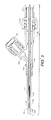
- FIG. 1A is a perspective view of a cardiac output Doppler catheter and an artery catheter to illustrate one embodiment of the invention.
- FIG. 1B is an exploded view of portions of FIG. 1A within the circle 1 B in FIG. 1A .
- FIG. 2 is a perspective view of the cardiac output Doppler catheter of FIG. 1A where the Doppler transducer extends through a Y shaped connector and inserted into the artery catheter.
- FIG. 3 is a cross-sectional view of one end of the Doppler catheter that includes the Doppler transducer and a cap for protecting the Doppler transducer.
- FIG. 4 is a cross-sectional view of the Y shaped connector of FIG. 1B and of the proximal end of the artery catheter connected to the Y shaped connector.
- FIG. 5 is a cross-sectional view of the Y shaped connector of FIG. 1B and one portion of the Doppler catheter that includes the Doppler transducer, a wire and a portion of a sleeve.
- FIG. 6A is a partly perspective and partly cross-sectional view of the cardiac output Doppler catheter and artery catheter of FIG. 1A and a connector with a port connected to a syringe and another port for connection to a pressure transducer to illustrate applications of one embodiment of the invention.
- FIG. 6B is an exploded view of a portion of the Doppler catheter and artery catheter of FIG. 6A within the circle 6 B in FIG. 6A .
- FIG. 7A is a perspective view of components of a portion of a cardiac output Doppler catheter to illustrate an alternative embodiment of the invention with two transducers.
- FIG. 7B is a cross-sectional view of components of a portion of a cardiac output Doppler catheter of FIG. 7A after the components are assembled.
- FIG. 7C is a cross-sectional view of a portion of the cardiac output Doppler catheter of FIG. 7A, 7B within the circle 7 C in FIG. 7B to illustrate the connections of power and ground leads to the Doppler transducer.
- FIG. 7D is a cross-sectional view of a portion of the cardiac output Doppler catheter of FIGS. 7A, 7B within the circle 7 D in FIG. 7B to illustrate the connections of power and ground leads to the transducer.
- FIG. 7E is a perspective view of components of a portion of a cardiac output Doppler catheter of FIG. 7A after the components are assembled.
- FIG. 8 is a schematic view of parts of the human body, including the heart and lung. This schematic also shows the positions of Doppler-tipped catheters and shows a computer, which can be used for determining the blood flow in a portion of the body.
- FIG. 1A is a perspective view of a cardiac output Doppler catheter 12 and an artery catheter 14 to illustrate one embodiment of the invention.
- FIG. 1B is an exploded perspective view of portions of the apparatus in FIG. 1A within the circle 1 B in FIG. 1A .
- the cardiac output Doppler catheter of FIG. 1A is intended to be placed within an artery.
- the distal end 14 a of an artery catheter 14 is first inserted into an artery (not shown) until its distal end 14 a is located at or near a location in the artery desirable for performing ultrasound measurements.
- the distal end 12 ′ of the cardiac output Doppler catheter 12 that contains a Doppler transducer 12 a and an electrical wire 12 b connected thereto are inserted at the proximal end 14 b of the artery catheter into a conduit 14 c (see FIGS. 4, 6B ) in the body of the artery catheter, where the insertion causes the Doppler transducer 12 a and the electrical wire 12 b to be moved relative to the conduit until the Doppler transducer 12 a exits the distal end 14 a of the artery catheter and is located at the desired location in the artery for performing ultrasound measurements.
- FIG. 2 is a perspective view of the cardiac output Doppler catheter 12 of FIG. 1A where the distal end 12 ′ of the Doppler catheter 12 containing Doppler transducer 12 a is inserted through a preferably Y shaped connector 16 into the artery catheter.
- FIG. 6B shows the relative positions of the Doppler transducer 12 a and the distal end 14 a of the artery catheter when the Doppler transducer 12 a is placed at a position suitable for performing ultrasound measurements in the artery. As shown in FIG.
- wire 12 b of the cardiac output Doppler catheter 12 is inside the conduit 14 c of the artery catheter 14 , with a portion of the wire and the Doppler transducer 12 a being outside of the conduit 14 c to be placed at a location in the artery suitable for performing ultrasound measurement of blood mean velocity.
- the Doppler transducer 12 a is protected by a Doppler tip layer 12 e shown more clearly in FIG. 7A .
- the advantage of the above arrangement is that since the Doppler transducer 12 a is placed in the artery it is measuring, the Doppler transducer can be positioned to send ultrasound waves in a direction substantially parallel to the blood flow and this greatly improves the accuracy of the ultrasound measurement of blood mean velocity in the artery. Another advantage is that continuous measurement of cardiac output can be provided.
- a first port 16 a at the distal end of a Y shaped connector 16 is attached to the artery catheter 14 at the proximal end 14 b of the artery catheter.
- the distal end 12 ′ of catheter 12 (containing Doppler transducer 12 a ) and the wire 12 b attached to the transducer are threaded through the Y shaped connector and inserted into a conduit (shown in FIGS. 4 and 6B ) within the body of artery catheter 14 .
- a conduit shown in FIGS. 4 and 6B
- the cardiac output Doppler catheter 12 includes a connector 12 c away from the proximal end 12 ′′ of the Doppler catheter 12 , and another connector 12 d at its proximal end 12 ′′.
- the cardiac output Doppler catheter 12 also includes a sleeve 12 f enclosing and protecting the wire 12 b from the environment.
- the wire 12 b is movable relative to connector 12 c , so that when the wire is moved from its position substantially all enclosed by sleeve 12 f as shown in FIG. 1A to a position as shown in FIG.
- the Y shaped connector 16 has at its proximal end a second port 16 b shaped so that the port mates with the connector 12 c (shown in FIG. 5 ) to form a stable and sturdy connection between the artery catheter 14 and the cardiac output Doppler catheter 12 .
- the Doppler transducer 12 a in distal end 12 ′ of catheter 12 and the wire 12 b are movable relative to port 16 a and this stable connection so as to insert or withdraw the Doppler transducer 12 a and the wire 12 b into or from the conduit in the artery catheter 14 .
- FIG. 3 is a cross-sectional view of the distal end 12 ′ of the Doppler catheter that contains the Doppler transducer, and of a cap 22 for protecting the Doppler transducer.
- cap 22 is shaped to mate with the connector 12 c when the Doppler catheter is not connected to the artery catheter body, to enclose and protect the Doppler transducer 12 a .
- the connector 12 c also centers the Doppler transducer 12 a when the Doppler transducer is inserted into the conduit in the body of the artery catheter 14 .
- FIG. 4 is a cross-sectional view of the Y shaped connector of FIG. 1B where the wire 12 b of the Doppler catheter 12 is not in the conduit 14 c of the artery catheter
- the proximal end 14 b of the artery catheter 14 is inserted into the distal end 16 a of the Y shaped connector 16
- a shrink tubing 17 fits snugly by a heat shrink process over the connection between the artery catheter 14 and the Y shaped connector 16 to reduce the stress on and chance of breakage of the artery catheter 14 .
- the Y shaped connector 16 includes a Touchy Borst valve that tightens around the Doppler catheter 12 when longitudinal pressure along direction 18 is applied to prevent blood from leaking past and around the Doppler catheter 12 when it is inserted into the conduit of the artery catheter 14 .
- FIG. 5 is a cross-sectional view of the Y shaped connector of FIG. 1B , the proximal end 14 b of artery catheter 14 and a portion of the Doppler catheter 12 that includes the wire 12 b and a portion of sleeve 12 f , where the wire 12 b of the Doppler catheter 12 is in the conduit 14 c of the artery catheter 14 .
- conduit 14 c has cross-sectional dimensions that are such that there is clearance 19 between the Doppler catheter 12 containing wire 12 b and the surface of the conduit 14 c . This allows a clear path between the third monitoring/infusion port 16 c (also shown in FIG.
- the monitoring/infusion port 16 c of connector 16 can also be used for infusion or injection of a substance such as crystalloids or hyperalimentation fluids.
- blood pressure monitoring, substance infusion or injection, and retrieval of blood samples in or from the artery can also be performed while blood mean velocity is being measured as described above, or when the Doppler catheter is not used for measuring blood mean velocity and wire 12 b is not in conduit 14 c .
- These functions may be performed by connecting the appropriate equipment to monitoring/infusion port 16 c through a port connector 21 that connects to and fits over port 16 c as shown in FIG. 5 .
- port 16 c and the port at the proximal end 16 b of the Y shaped connector 16 may be enclosed by means of connectors 23 as shown in FIG. 4 .
- the elongated catheter body of the artery catheter 14 comprises a material firm enough to enable the body to be inserted into arteries, but flexible enough to bend along turns in the arteries, such as turns in an umbilical artery in newborns.
- the elongated catheter body of the artery catheter 14 comprises a polyurethane material.
- connector 16 preferably is Y-shaped, it will be understood that connector 16 may be in shapes other than Y; such variations are within the scope of the invention.
- the monitoring/infusion port 16 c of connector 16 is located between ports 16 a and 16 b at the distal and proximal ends of the connector respectively.
- FIG. 6A is a partly perspective and partly cross-sectional view of the cardiac output Doppler catheter 12 and artery catheter 14 of FIG. 1A and of a connector 16 with the monitoring/infusion port 16 c port connected to yet another connector 24 with two ports: a port connected to a syringe 26 and another port connected to a pressure transducer 28 to illustrate applications of one embodiment of the invention.
- the connector 24 contains a valve (not shown) therein to allow either the syringe 26 or the pressure transducer 28 , but not both, to be connected to port 16 c at any one time.
- Part of the cardiac output Doppler catheter 12 is truncated and not shown in FIG. 6A .
- FIG. 6A Part of the cardiac output Doppler catheter 12 is truncated and not shown in FIG. 6A .
- FIG. 6B is an exploded view of a portion of the Doppler catheter and artery catheter of FIG. 6A within the circle 6 B in FIG. 6A .
- the blood pressure in the artery may be monitored by means of a pressure transducer 28 providing a pressure reading at an output.
- Substances may also be injected into the artery through connectors 16 and 24 by means of syringe 26 .
- FIG. 7A is a perspective view of components of a portion of a cardiac output Doppler catheter 112 to illustrate an alternative embodiment of the invention with two transducers.
- FIG. 7B is a cross-sectional view of components of the distal end of the cardiac output Doppler catheter of FIG. 7A after the components are assembled.
- FIGS. 7C, 7D are cross-sectional views of portions of the cardiac output Doppler catheter of FIGS. 7A, 7B to illustrate the connections of power and ground leads to the two transducers.
- cardiac output Doppler catheter 112 of FIGS. 7A-7E includes at least two transducers: Doppler transducer 12 a as in the embodiments described above, but also at least a second transducer 52 .
- Transducers 12 a , 52 comprise piezo crystals # 1 and # 2 respectively as shown in FIG. 7A .
- Cardiac output Doppler catheter 112 includes a housing 114 for the piezo crystal # 1 , which is protected by the housing 114 and a matching layer 12 e from the environment in the artery.
- Power lead 116 is electrically connected to piezo crystal # 1 , and an optional ground lead 118 is preferably electrically connected to housing 114 (connections shown in dashed lines in FIG. 7A ).
- Cardiac output Doppler catheter 112 also includes a housing 124 for the piezo crystal # 2 , which is protected by the housing 124 and a matching layer 122 from the environment in the artery.
- Power lead 126 is electrically connected to piezo crystal # 2
- an optional ground lead 128 is preferably electrically connected to housing 124 (connections shown in dashed lines in FIG. 7A ).
- FIG. 7B is a cross-sectional view of components of the distal end of the cardiac output Doppler catheter 112 of FIG. 7A after the components are assembled.
- FIG. 7C is a cross-sectional view of a portion of the cardiac output Doppler catheter of FIG. 7A, 7B within the circle 7 C in FIG. 7B to illustrate the connections of power and ground leads to the Doppler transducer 12 a .
- FIG. 7D is a cross-sectional view of a portion of the cardiac output Doppler catheter of FIGS. 7A, 7B within the circle 7 D in FIG. 7B to illustrate the connections of power and ground leads to the transducer 52 .
- the alternative embodiment of FIGS. 7A-7E uses the same components and functions in the same manner as the embodiments of FIGS. 1A through 6B for measuring blood mean velocity.
- the advantage of having at least a second transducer that is employed on the side of the Doppler catheter 12 is that this second transducer can be used for measuring a cross-sectional dimension of the artery. This can be done by simply detecting the time of travel of sound waves and its reflection between the second transducer and an adjacent wall of the artery. The distance between the transducer and the artery wall can then be calculated from the time measured and the speed of sound in the blood. If it can be assumed that the Doppler catheter 12 is placed at the central axis of the artery and that the artery has a substantially circular cross-section, then the cross-sectional dimension of the artery can be computed from this time measurement, and from the speed of sound in the blood.
- the Doppler catheter 12 may be rotated in the artery so that the only one side transducer is used to measure multiple (e.g. at least two) cross-sectional dimensions of the artery at two or more different angular orientations of the Doppler catheter relative to the artery. More accurate cross-section dimensions of the artery can then be derived from the above measurements.
- the ultrasound measurement provided by the Doppler transducer provides the blood mean velocity. Blood volume flow or cardiac output can then be computed from this mean velocity and the cross-sectional dimensions of the artery. Blood pressure monitoring, substance infusion or injection, and retrieval of blood samples in or from the artery can be performed while blood flow is being measured as described above, or when the Doppler catheter is not used for measuring blood flow and the Doppler catheter is not in conduit 14 c.
- FIG. 8 is a schematic view of parts of the body, including the heart 210 and lungs 212 .
- the heart is divided into the right atrium 210 a and right ventricle 210 b , and the left atrium 210 c and left ventricle 210 d .
- the pulmonary artery 214 connects the right ventricle 210 b to the lungs 212 .
- the aorta 216 is a passage through which blood goes to the different parts of the body. In a fetus and neonatal patient, the pulmonary artery 214 and aorta 216 are connected by the ductus arteriosus 218 .
- FIG. 8 shows two positions in which a catheter can be placed into the arteries to determine the blood flow of the patient.
- Doppler-tipped catheter 220 (which can be any one of the embodiments described above) is positioned down through the heart past the ductus arteriosus in the pulmonary artery 214 . Notice that the tip of the Doppler-tipped catheter 220 a is near but facing away from the ductus arteriosus 218 .
- Doppler-tipped catheter 222 is placed through the umbilical cord up through the aorta 16 to a position near and facing the ductus arteriosus 218 .
- the velocity of blood in the bloodstream can be determined with the use of a Doppler-tipped catheter in a manner such that the cardiac output or blood flow Q can be computed from the blood mean velocity and the cross-sectional area of the blood vessel.
- the mean velocity is determined using the Doppler shift in the frequency between the transmitted signal and the received signal. This shift is proportional to the blood velocity.
- Catheter 220 a will show decreased flow. Conversely, if the pressure is inadequate, the blood supply remains adequate but the gas supply is reduced—normal Q with decreased V. Please note that the concentration of oxygen may be adequate, just that the surface area available for gas exchange is reduced. In the last case, catheter 220 a will show normal flow.
- Right to left shunting is used loosely with any condition that leads to inadequate oxygenation of the body.
- Left to right shunting refers to excess blood supply to the lung.
- the Doppler-tipped catheter placed into an artery of the patient can help determine shunt fractions through the ductus arteriosus 18 .
- the frequency shift signal from the Doppler-tipped catheter will provide the blood flow velocity toward (antegrade) or away from (retrograde) the catheter.
- the positive portion of the frequency shift signal gives an indication of the antegrade blood flow through the aorta 216 to the body.
- the negative portion gives an indication of the left-to-right shunting of retrograde blood flow through the ductus arteriosus 218 . In this manner, the shunt fraction through the ductus arteriosus 218 can be determined.
- the 8 will have a retrograde portion of a frequency shift data which corresponds to the blood flow from the right ventricle 210 d to the lungs 212 , with an antegrade portion which shows the right-to-left shunting through the ductus arteriosus 218 .
- the signal from the velocimeter connected to the catheter can be set to measure blood flow velocity toward (antegrade) or away from (retrograde) the catheter.
- the software in the computer 224 switches the velocimeter so as to alternately analyze the antegrade and retrograde portion of the signal every 50 milliseconds.
- the above sections are essentially taken from U.S. Pat. No. 5,433,205.
- the artery into which Doppler catheter 12 and 112 may be placed as described above can be the radial, pulmonary, femoral or umbilical artery. Where the artery is an umbilical artery of a neonatal patient, said location for locating the Doppler transducer 12 a is close to the patent ductus arteriosus of the patient, and the ultrasound measurement measures antegrade and retrograde blood velocity.
- the analysis and computations mentioned above may be performed using computer 224 of FIG. 8 .
- blood pressure may be monitored while Doppler ultrasound measurements are performed.
- both the blood velocity (or blood flow in the case of Doppler catheter 112 ) and information related to the blood pressure measurement may be displayed at substantially the same time on display 226 in FIG. 8 , in real time and continuously if desired.
- a cardiac assist device 250 may be placed in the aorta 216 as shown in FIG. 8 or the left ventricle 210 d (shown as 250 ′ in dashed lines). If placed in the aorta 216 , and the catheter 220 a is at the position shown in FIG. 8 , catheter 220 a may be used as shown in FIG. 8 to measure the velocity of the combined blood flow in the aorta and cardiac assist device. If placed in the left ventricle 210 d , catheter 220 a may be advanced to a location (not shown) in tandem or within cardiac assist device 250 ′ to measure the blood velocity in the cardiac assist device 250 ′. If the catheter 220 a is to be used in this manner, the elongated catheter body of catheter 220 a may comprise a material rigid enough to be placed in tandem or within cardiac assist devices, and can contain metal.
- a systolic time interval parameter can also be derived from a result of the Doppler measurement described above.
- Ahmed et al. “Systolic Time Intervals as Measures of the Contractile State of the Left Ventricular Myocardium in Man,” Journal of the American Heart Association, Circulation, Vol. XLVI, September 1972, pp. 559-571.
Abstract
An apparatus for performing measurements in an artery includes a Doppler catheter, comprising a Doppler transducer and a wire connected to the Doppler transducer; and an elongated catheter body having a conduit therein for housing the wire of the Doppler catheter. The body has a proximal end and a distal end; wherein the wire is movable in the conduit relative to the catheter body so that the Doppler transducer and the wire are capable of being threaded into said conduit at the proximal end after the distal end of the catheter has been inserted into the artery, until the Doppler transducer emerges outside the conduit at the distal end of said body for performing ultrasound measurements in the artery. Another embodiment employs at least an additional side transducer for measuring the cross-sectional dimension of the artery useful for computing blood flow.
Description
This application is a continuation of U.S. patent application Ser. No. 14/789,137 filed Jul. 1, 2015, which is a divisional of U.S. patent application Ser. No. 14/326,034 filed Jul. 8, 2014, both of which are incorporated by reference herein for all purposes.
This invention relates in general to systems and methods for measuring arteries and in particular to systems and methods for measuring parameters related to blood in arteries.
Conventional methods for measuring arterial blood mean velocity include Doppler echocardiography and Cardiac Catheterization. Non Invasive Doppler echocardiography used for measuring blood mean velocity in arteries employs a Doppler transducer outside the arteries to transmit ultrasound to the arteries, and must be conducted so that the sound waves are directed to the arteries at angles not more than about 15 degrees from the direction of blood flow. Otherwise, the blood mean velocity measurement is not accurate. For certain locations of the human body, this may not be practical. Conventional cardiac catheterization cannot provide continuous measurement of cardiac output. It is therefore desirable to provide improved systems and methods for measuring arterial blood mean velocity and cardiac output with related derived indices of cardiac function.
One embodiment of the invention is directed to an apparatus for performing measurements in an artery, comprising a Doppler catheter, including a Doppler transducer and a wire connected to the Doppler transducer; and an elongated catheter body having a conduit therein for housing the wire of the Doppler catheter. The body has a proximal end and a distal end; wherein the wire is movable in the conduit relative to the catheter body so that the Doppler transducer and the wire are capable of being threaded into said conduit at the proximal end after the distal end of the catheter has been inserted into the artery, until the Doppler transducer emerges outside the conduit at the distal end of said body for performing ultrasound measurements in the artery.
Another embodiment of the invention is directed to a method for measuring blood mean velocity in an artery, comprising inserting into the artery an elongated catheter body having a proximal end and a distal end so that the distal end is located at a desired location in the artery for measuring blood mean velocity, the body defining therein a conduit therein. Thereafter inserted into the conduit at the proximal end of the body is a Doppler catheter that includes a Doppler transducer and a wire connected to the Doppler transducer so that the Doppler transducer passes through and extends outside the conduit to be located at said desired location. Ultrasound measurement of the blood mean velocity in the artery at said desired location using the Doppler transducer is performed.
Yet another embodiment of the invention is directed to an apparatus for performing measurements in an artery, comprising a Doppler catheter which includes a Doppler transducer, a second transducer and wires connected to the Doppler transducer and the second transducer. The Doppler catheter is suitable for being inserted and withdrawn from a conduit in an elongated catheter body having the conduit therein for housing the wire of the Doppler catheter. The body has a proximal end and a distal end; wherein said wires are movable in the conduit relative to the catheter body so that the Doppler transducer, the second transducer and the wires are capable of being threaded into said conduit at the proximal end after the distal end of the catheter has been inserted into the artery, until the Doppler transducer and the second transducer emerge outside the conduit at the distal end of said body for performing ultrasound measurement in and measurement of a cross-sectional dimension of the artery.
All patents, patent applications, articles, books, specifications, other publications, documents and things referenced herein are hereby incorporated herein by this reference in their entirety for all purposes. To the extent of any inconsistency or conflict in the definition or use of a term between any of the incorporated publications, documents or things and the text of the present document, the definition or use of the term in the present document shall prevail.
Identical components are labeled by the same numerals in this document.
Identical components are labeled by the same numerals in this document.
Ultrasound measurements are then performed in a conventional manner using the Doppler transducer 12 a. FIG. 2 is a perspective view of the cardiac output Doppler catheter 12 of FIG. 1A where the distal end 12′ of the Doppler catheter 12 containing Doppler transducer 12 a is inserted through a preferably Y shaped connector 16 into the artery catheter. FIG. 6B shows the relative positions of the Doppler transducer 12 a and the distal end 14 a of the artery catheter when the Doppler transducer 12 a is placed at a position suitable for performing ultrasound measurements in the artery. As shown in FIG. 6B , wire 12 b of the cardiac output Doppler catheter 12 is inside the conduit 14 c of the artery catheter 14, with a portion of the wire and the Doppler transducer 12 a being outside of the conduit 14 c to be placed at a location in the artery suitable for performing ultrasound measurement of blood mean velocity. The Doppler transducer 12 a is protected by a Doppler tip layer 12 e shown more clearly in FIG. 7A .
The advantage of the above arrangement is that since the Doppler transducer 12 a is placed in the artery it is measuring, the Doppler transducer can be positioned to send ultrasound waves in a direction substantially parallel to the blood flow and this greatly improves the accuracy of the ultrasound measurement of blood mean velocity in the artery. Another advantage is that continuous measurement of cardiac output can be provided.
As shown in FIGS. 1A and 1B , a first port 16 a at the distal end of a Y shaped connector 16 is attached to the artery catheter 14 at the proximal end 14 b of the artery catheter. As shown in FIG. 2 , the distal end 12′ of catheter 12 (containing Doppler transducer 12 a) and the wire 12 b attached to the transducer are threaded through the Y shaped connector and inserted into a conduit (shown in FIGS. 4 and 6B ) within the body of artery catheter 14. As shown in FIGS. 1A and 1B , the cardiac output Doppler catheter 12 includes a connector 12 c away from the proximal end 12″ of the Doppler catheter 12, and another connector 12 d at its proximal end 12″. The cardiac output Doppler catheter 12 also includes a sleeve 12 f enclosing and protecting the wire 12 b from the environment. The wire 12 b is movable relative to connector 12 c, so that when the wire is moved from its position substantially all enclosed by sleeve 12 f as shown in FIG. 1A to a position as shown in FIG. 2 where most of the wire 12 b extends outside the sleeve and is inserted into the conduit of the artery catheter 14, the distal end of the wire 12 b (and transducer 12 a) is moved past the connector 12 c and the Y shaped connector 16 in a forward direction 18. But when the wire 12 b is withdrawn from the conduit and moved past the connector 12 c back into the sleeve 12 f in a direction opposite to direction 18, the distal end of the wire 12 b connected to the transducer 12 a is then located near the connector 12 c as shown in FIG. 1A .
The Y shaped connector 16 has at its proximal end a second port 16 b shaped so that the port mates with the connector 12 c (shown in FIG. 5 ) to form a stable and sturdy connection between the artery catheter 14 and the cardiac output Doppler catheter 12. The Doppler transducer 12 a in distal end 12′ of catheter 12 and the wire 12 b are movable relative to port 16 a and this stable connection so as to insert or withdraw the Doppler transducer 12 a and the wire 12 b into or from the conduit in the artery catheter 14.
The sleeve 12 f is shorter than the wire 12 b so that when the wire is withdrawn from the conduit in the artery catheter 14, the sleeve limits the extent by which the wire is withdrawn from the conduit. FIG. 3 is a cross-sectional view of the distal end 12′ of the Doppler catheter that contains the Doppler transducer, and of a cap 22 for protecting the Doppler transducer. As shown in FIG. 3 , cap 22 is shaped to mate with the connector 12 c when the Doppler catheter is not connected to the artery catheter body, to enclose and protect the Doppler transducer 12 a. The connector 12 c also centers the Doppler transducer 12 a when the Doppler transducer is inserted into the conduit in the body of the artery catheter 14.
Preferably, the elongated catheter body of the artery catheter 14 comprises a material firm enough to enable the body to be inserted into arteries, but flexible enough to bend along turns in the arteries, such as turns in an umbilical artery in newborns. In one embodiment, the elongated catheter body of the artery catheter 14 comprises a polyurethane material. While connector 16 preferably is Y-shaped, it will be understood that connector 16 may be in shapes other than Y; such variations are within the scope of the invention. Preferably the monitoring/infusion port 16 c of connector 16 is located between ports 16 a and 16 b at the distal and proximal ends of the connector respectively.
As shown in FIG. 7AE instead of having only one Doppler transducer 12 a as in the embodiments described above, cardiac output Doppler catheter 112 of FIGS. 7A-7E includes at least two transducers: Doppler transducer 12 a as in the embodiments described above, but also at least a second transducer 52. Transducers 12 a, 52 comprise piezo crystals #1 and #2 respectively as shown in FIG. 7A . Cardiac output Doppler catheter 112 includes a housing 114 for the piezo crystal #1, which is protected by the housing 114 and a matching layer 12 e from the environment in the artery. Power lead 116 is electrically connected to piezo crystal #1, and an optional ground lead 118 is preferably electrically connected to housing 114 (connections shown in dashed lines in FIG. 7A ). Cardiac output Doppler catheter 112 also includes a housing 124 for the piezo crystal #2, which is protected by the housing 124 and a matching layer 122 from the environment in the artery. Power lead 126 is electrically connected to piezo crystal #2, and an optional ground lead 128 is preferably electrically connected to housing 124 (connections shown in dashed lines in FIG. 7A ). The housings 114 and 124 are then connected together by sections 132, 134 of a jacket 1 and section 136 of jacket 2 to form the distal end of cardiac output Doppler catheter 112, where the leads 116, 128, 126, 128 are housed within the sections. FIG. 7B is a cross-sectional view of components of the distal end of the cardiac output Doppler catheter 112 of FIG. 7A after the components are assembled.
The advantage of having at least a second transducer that is employed on the side of the Doppler catheter 12 is that this second transducer can be used for measuring a cross-sectional dimension of the artery. This can be done by simply detecting the time of travel of sound waves and its reflection between the second transducer and an adjacent wall of the artery. The distance between the transducer and the artery wall can then be calculated from the time measured and the speed of sound in the blood. If it can be assumed that the Doppler catheter 12 is placed at the central axis of the artery and that the artery has a substantially circular cross-section, then the cross-sectional dimension of the artery can be computed from this time measurement, and from the speed of sound in the blood. If the artery does not have a substantially circular cross-section, employing additional transducers located at different positions around a circumference or perimeter of the Doppler catheter will provide measurement of distances between the Doppler catheter and the artery wall at multiple positions around a circumference or perimeter of the artery to yield multiple (e.g. at least two) cross-sectional dimensions of the artery. Alternatively, instead of using more than one transducer (side transducer) located on the side of Doppler catheter 12, the Doppler catheter 12 may be rotated in the artery so that the only one side transducer is used to measure multiple (e.g. at least two) cross-sectional dimensions of the artery at two or more different angular orientations of the Doppler catheter relative to the artery. More accurate cross-section dimensions of the artery can then be derived from the above measurements.
The ultrasound measurement provided by the Doppler transducer provides the blood mean velocity. Blood volume flow or cardiac output can then be computed from this mean velocity and the cross-sectional dimensions of the artery. Blood pressure monitoring, substance infusion or injection, and retrieval of blood samples in or from the artery can be performed while blood flow is being measured as described above, or when the Doppler catheter is not used for measuring blood flow and the Doppler catheter is not in conduit 14 c.
The different embodiments above may be used for measurements and display of information as described in U.S. Pat. No. 5,433,205, which is incorporated herein in its entirety by reference. Sections below are taken from this patent to illustrate how the different embodiments above may be used. FIG. 8 of this document contains the same information as FIG. 1 of U.S. Pat. No. 5,433,205.
An important part of monitoring the ventilation perfusion match is monitoring the blood flow in the body. When patients are on life support systems, oxygen is pumped under pressure into the lung 212 at high concentrations. Thus, if the surface area of the lung 212 available for gas exchange is decreased by disease, e.g. pneumonia, the higher concentration of oxygen will provide an adequate amount of oxygen to the body through the available surface area. Sometimes the lung 212 tends to collapse or have poor compliance, as in premature infants. Pressure to deliver the oxygen and open the lungs then becomes essential. However, excess pressure will over-distend the alveoli and squeeze the surrounding blood out, causing an inadequate availability of blood for gas exchange. In this case, due to over-distension, ventilation V is increased; however, due to the squeeze effect, Q is decreased. Catheter 220 a will show decreased flow. Conversely, if the pressure is inadequate, the blood supply remains adequate but the gas supply is reduced—normal Q with decreased V. Please note that the concentration of oxygen may be adequate, just that the surface area available for gas exchange is reduced. In the last case, catheter 220 a will show normal flow.
Right to left shunting is used loosely with any condition that leads to inadequate oxygenation of the body. Left to right shunting refers to excess blood supply to the lung.
The ductus arteriosus 218 complicates the above picture. If this conduit between the pulmonary artery, the main blood vessel to the lung, and the aorta, the main blood vessel in the body, does not close, the blood takes the path of least resistance and may bypass the lung completely. This effect is caused by excess pressure or over-distension of the lung described above—right to left shunting with V/Q>1. On the other hand, normally the pressure in the aorta is higher than that of the pulmonary artery. Hence, if the ductus is open, the blood will leak back into the lungs—left to right shunting with V/Q<1. Catheter 222 a will show retrograde flow and catheter 220 a will show increased antegrade flow. This assumes that normal V/Q=1.
The Doppler-tipped catheter placed into an artery of the patient can help determine shunt fractions through the ductus arteriosus 18. The frequency shift signal from the Doppler-tipped catheter will provide the blood flow velocity toward (antegrade) or away from (retrograde) the catheter. The positive portion of the frequency shift signal gives an indication of the antegrade blood flow through the aorta 216 to the body. The negative portion gives an indication of the left-to-right shunting of retrograde blood flow through the ductus arteriosus 218. In this manner, the shunt fraction through the ductus arteriosus 218 can be determined. Alternately, a Doppler-tipped catheter 220 of FIG. 8 will have a retrograde portion of a frequency shift data which corresponds to the blood flow from the right ventricle 210 d to the lungs 212, with an antegrade portion which shows the right-to-left shunting through the ductus arteriosus 218. The signal from the velocimeter connected to the catheter can be set to measure blood flow velocity toward (antegrade) or away from (retrograde) the catheter. The software in the computer 224 switches the velocimeter so as to alternately analyze the antegrade and retrograde portion of the signal every 50 milliseconds.
The above sections are essentially taken from U.S. Pat. No. 5,433,205. The artery into which Doppler catheter 12 and 112 may be placed as described above can be the radial, pulmonary, femoral or umbilical artery. Where the artery is an umbilical artery of a neonatal patient, said location for locating the Doppler transducer 12 a is close to the patent ductus arteriosus of the patient, and the ultrasound measurement measures antegrade and retrograde blood velocity. The analysis and computations mentioned above may be performed using computer 224 of FIG. 8 . As described above, blood pressure may be monitored while Doppler ultrasound measurements are performed. Thus, both the blood velocity (or blood flow in the case of Doppler catheter 112) and information related to the blood pressure measurement may be displayed at substantially the same time on display 226 in FIG. 8 , in real time and continuously if desired.
A cardiac assist device 250 may be placed in the aorta 216 as shown in FIG. 8 or the left ventricle 210 d (shown as 250′ in dashed lines). If placed in the aorta 216, and the catheter 220 a is at the position shown in FIG. 8 , catheter 220 a may be used as shown in FIG. 8 to measure the velocity of the combined blood flow in the aorta and cardiac assist device. If placed in the left ventricle 210 d, catheter 220 a may be advanced to a location (not shown) in tandem or within cardiac assist device 250′ to measure the blood velocity in the cardiac assist device 250′. If the catheter 220 a is to be used in this manner, the elongated catheter body of catheter 220 a may comprise a material rigid enough to be placed in tandem or within cardiac assist devices, and can contain metal.
A systolic time interval parameter can also be derived from a result of the Doppler measurement described above. For details of such derivation, please see Ahmed et al., “Systolic Time Intervals as Measures of the Contractile State of the Left Ventricular Myocardium in Man,” Journal of the American Heart Association, Circulation, Vol. XLVI, September 1972, pp. 559-571.
While the invention has been described above by reference to various embodiments, it will be understood that changes and modifications may be made without departing from the scope of the invention, which is to be defined only by the appended claims and their equivalents.
Claims (25)
1. An apparatus for performing measurements in an artery, comprising:
a Doppler transducer;
a wire, capable of carrying an electrical signal along a length of the wire, the wire having a distal end connected to the Doppler transducer at a distal portion of the wire, and the wire having a proximal end;
a first connector having an opening through which the wire would pass during operation of the apparatus;
a second connector at the proximal end of the wire, suitable for electrical connections to the wire;
a catheter body having a proximal end and a distal end and having a conduit therein for containing portions of the wire;
an enclosing sleeve having a first position and a second position wherein, when in the first position, the enclosing sleeve encloses substantially all of the wire save for the distal portion of the wire connected to the Doppler transducer, and wherein, when in the second position, the enclosing sleeve does not enclose a majority of the wire and unenclosed portions of the wire would pass into the conduit of the catheter body;
a third connector attached to the catheter body at the proximal end of the catheter body, shaped to mate with the first connector to form a stable connection between the catheter body and the enclosing sleeve;
wherein, after the stable connection has been formed, the wire and Doppler transducer are movable in the conduit through the stable connection with movement of the Doppler transducer being from around the proximal end of the catheter body to beyond the distal end of the catheter body, whereby the Doppler transducer can emerge outside the conduit at the distal end of the catheter body for performing ultrasound measurements in the artery; and
wherein the enclosing sleeve provides a barrier between the wire and an environment when the wire is withdrawn from the catheter body.
2. The apparatus of claim 1 , wherein the enclosing sleeve is shorter than the wire such that when the wire is withdrawn from the conduit, the length of the enclosing sleeve limits an extent by which the wire can be withdrawn from the conduit.
3. The apparatus of claim 1 , further comprising a cap for connection to the first connector when the Doppler transducer and wire are not connected to the catheter body, to enclose and protect the Doppler transducer.
4. The apparatus of claim 1 , wherein the first connector provides centering for the Doppler transducer for when the Doppler transducer is inserted into the conduit of the catheter body.
5. The apparatus of claim 1 , wherein the third connector comprises:
a first port that permits the Doppler transducer and the wire to pass there through and be inserted into the conduit;
a second port coupled to the proximal end of the catheter body; and
a third port providing a clear path enabling blood pressure in the artery near the distal end of the catheter body to be monitored through the second port whether or not the Doppler transducer and the wire are in the conduit.
6. The apparatus of claim 1 , wherein the third connector comprises:
a first port that permits the Doppler transducer and the wire to pass there through and be inserted into the conduit;
a second port coupled to the proximal end of the catheter body; and
a third port providing a clear path enabling infusion of a substance to the artery, retrieval of blood samples, or monitoring blood pressure in the artery near the distal end of the catheter body.
7. The apparatus of claim 6 , wherein the third port provides the clear path whether or not the Doppler transducer and the wire are in the conduit.
8. The apparatus of claim 6 , wherein the third connector is Y-shaped.
9. The apparatus of claim 8 , wherein the third port is located on the third connector between the first port and the second port.
10. The apparatus of claim 1 , wherein the catheter body comprises a material firm enough to enable the catheter body to be inserted into arteries but flexible enough to bend along turns in the arteries as in an umbilical artery in newborns.
11. The apparatus of claim 1 , wherein the catheter body comprises a material rigid enough to be placed in tandem with a cardiac assist device or within the cardiac assist device.
12. The apparatus of claim 1 , wherein the catheter body comprises polyurethane or metal.
13. The apparatus of claim 1 , further comprising at least one second transducer for measuring at least one cross-sectional dimension of the artery, and at least one second wire connected to the at least one second transducer.
14. The apparatus of claim 13 , further comprising:
ground wires for the Doppler transducer and the second transducer; and
a housing containing the wire, the at least one second wire and the ground wires with the ground wires connected to the housing.
15. The apparatus of claim 13 , wherein the Doppler transducer or the second transducer are used for measuring blood mean velocity in the artery.
16. The apparatus of claim 1 , wherein the Doppler transducer is configured to be positioned to send ultrasound waves in a direction substantially parallel to blood flow for ultrasound measurement of blood mean velocity in the artery.
17. The apparatus of claim 1 , wherein the Doppler transducer is configured to provide continuous measurement of cardiac output.
18. An apparatus for performing measurements in an artery, comprising:
a Doppler transducer;
a second transducer;
a wire set comprising a plurality of wires, capable of carrying an electrical signal along a length of the wire set, the wire set having a proximal end and having a distal end with at least one wire of the wire set connected to the Doppler transducer at a distal portion of the wire set and at least one other wire of the wire set connected to the second transducer at the distal portion of the wire set;
a first connector having an opening through which the wire set would pass during operation of the apparatus;
a second connector at the proximal end of the wire set, suitable for electrical connections to connected wires of the plurality of wires;
a catheter body having a proximal end and a distal end and having a conduit therein for containing portions of the wire set;
an enclosing sleeve having a first position and a second position wherein, when in the first position, the enclosing sleeve encloses substantially all of the wire set save for the distal portion of the wire set connected to the Doppler transducer and the second transducer, and wherein, when in the second position, the enclosing sleeve does not enclose a majority of the wire set and unenclosed portions of the wire set would pass into the conduit of the catheter body;
a third connector attached to the catheter body at the proximal end of the catheter body, shaped to mate with the first connector to form a stable connection between the catheter body and the enclosing sleeve;
wherein, after the stable connection has been formed, the wire set, the Doppler transducer and the second transducer are movable in the conduit through the stable connection with movement of the Doppler transducer and the second transducer being from around the proximal end of the catheter body to beyond the distal end of the catheter body, whereby the Doppler transducer and the second transducer can emerge outside the conduit at the distal end of the catheter body for performing ultrasound measurements in the artery after the distal end of the catheter body has been inserted into the artery for performing ultrasound measurement in the artery and measurement of a cross-sectional dimension of the artery; and
wherein the enclosing sleeve provides a barrier between the wire set and an environment when the wire set is withdrawn from the catheter body.
19. A method for performing measurements in an artery, comprising:
providing a Doppler transducer and a wire capable of carrying an electrical signal along a length of the wire, the wire having a distal end connected to the Doppler transducer at a distal portion of the wire, and the wire having a proximal end;
inserting, into a patient, a catheter body having a proximal end and a distal end and having a conduit therein for containing portions of the wire;
moving an enclosing sleeve from a first position to a second position, the first position being wherein the enclosing sleeve encloses substantially all of the wire save for the distal portion of the wire connected to the Doppler transducer, and the second position being wherein the enclosing sleeve does not enclose a majority of the wire and unenclosed portions of the wire would pass into the conduit of the catheter body, while the wire is sterile and the enclosing sleeve provides a barrier between the wire and an environment at least in the first position;
wherein moving the enclosing sleeve from the first position to the second position moves the wire and Doppler transducer in the conduit;
positioning the wire such that the Doppler transducer emerges outside the conduit at the distal end of the catheter body for performing ultrasound measurements in the artery; and
making an ultrasound measurement.
20. The method of claim 19 , wherein the ultrasound measurement comprises measuring retrograde flow and antegrade flow.
21. The method of claim 19 , further comprising:
measuring antegrade blood flow through an aorta of the patient to a body of the patient;
measuring retrograde blood flow through a ductus arteriosus of the patient; and
determining, in real time, a shunt fraction through the ductus arteriosus.
22. The method of claim 19 , further comprising:
providing a second transducer; and
measuring a time of travel of sound waves and their reflection between the second transducer and an adjacent wall of the artery for use in determining a distance between the second transducer and the adjacent wall of the artery.
23. The method of claim 22 , further comprising:
providing additional transducers; and
making additional time of travel measurements in a plurality of directions to determine a plurality of distances between the additional transducers and the adjacent wall of the artery for noncircular cross-section arteries.
24. The method of claim 22 , further comprising:
rotating the second transducer to obtain additional time of travel measurements in a plurality of directions to determine a plurality of distances between the second transducer and the adjacent wall of the artery for noncircular cross-section arteries.
25. The method of claim 19 , further comprising positioning the Doppler transducer to be proximate to a patent ductus arteriosus of a neonatal patient before making the ultrasound measurement.
Priority Applications (1)
| Application Number | Priority Date | Filing Date | Title |
|---|---|---|---|
| US15/356,280 US9795359B2 (en) | 2014-07-08 | 2016-11-18 | System and method for measuring fluidics in arteries |
Applications Claiming Priority (3)
| Application Number | Priority Date | Filing Date | Title |
|---|---|---|---|
| US14/326,034 US9320493B2 (en) | 2014-07-08 | 2014-07-08 | System and method for measuring fluidics in arteries |
| US14/789,137 US9504443B2 (en) | 2014-07-08 | 2015-07-01 | System and method for measuring fluidics in arteries |
| US15/356,280 US9795359B2 (en) | 2014-07-08 | 2016-11-18 | System and method for measuring fluidics in arteries |
Related Parent Applications (1)
| Application Number | Title | Priority Date | Filing Date |
|---|---|---|---|
| US14/789,137 Continuation US9504443B2 (en) | 2014-07-08 | 2015-07-01 | System and method for measuring fluidics in arteries |
Publications (2)
| Publication Number | Publication Date |
|---|---|
| US20170065251A1 US20170065251A1 (en) | 2017-03-09 |
| US9795359B2 true US9795359B2 (en) | 2017-10-24 |
Family
ID=55066106
Family Applications (3)
| Application Number | Title | Priority Date | Filing Date |
|---|---|---|---|
| US14/326,034 Active US9320493B2 (en) | 2014-07-08 | 2014-07-08 | System and method for measuring fluidics in arteries |
| US14/789,137 Active US9504443B2 (en) | 2014-07-08 | 2015-07-01 | System and method for measuring fluidics in arteries |
| US15/356,280 Active US9795359B2 (en) | 2014-07-08 | 2016-11-18 | System and method for measuring fluidics in arteries |
Family Applications Before (2)
| Application Number | Title | Priority Date | Filing Date |
|---|---|---|---|
| US14/326,034 Active US9320493B2 (en) | 2014-07-08 | 2014-07-08 | System and method for measuring fluidics in arteries |
| US14/789,137 Active US9504443B2 (en) | 2014-07-08 | 2015-07-01 | System and method for measuring fluidics in arteries |
Country Status (1)
| Country | Link |
|---|---|
| US (3) | US9320493B2 (en) |
Families Citing this family (18)
| Publication number | Priority date | Publication date | Assignee | Title |
|---|---|---|---|---|
| US8781555B2 (en) | 2007-11-26 | 2014-07-15 | C. R. Bard, Inc. | System for placement of a catheter including a signal-generating stylet |
| ES2651898T3 (en) | 2007-11-26 | 2018-01-30 | C.R. Bard Inc. | Integrated system for intravascular catheter placement |
| US9521961B2 (en) | 2007-11-26 | 2016-12-20 | C. R. Bard, Inc. | Systems and methods for guiding a medical instrument |
| US9532724B2 (en) | 2009-06-12 | 2017-01-03 | Bard Access Systems, Inc. | Apparatus and method for catheter navigation using endovascular energy mapping |
| EP2912999B1 (en) | 2010-05-28 | 2022-06-29 | C. R. Bard, Inc. | Apparatus for use with needle insertion guidance system |
| CA3044652C (en) | 2015-08-28 | 2023-08-08 | Crisi Medical Systems, Inc. | Flow sensor system including spring contacts |
| EP3341052B1 (en) * | 2015-08-28 | 2021-09-29 | Crisi Medical Systems, Inc. | Flow sensor system with absorber |
| EP3653240B1 (en) | 2015-08-28 | 2022-08-24 | Crisi Medical Systems, Inc. | Flow sensor system including transmissive connection |
| US10258742B2 (en) | 2016-06-17 | 2019-04-16 | Becton, Dickinson And Company | Method and apparatus for wetting internal fluid path surfaces of a fluid port to increase ultrasonic signal transmission |
| US11020563B2 (en) | 2016-07-14 | 2021-06-01 | C. R. Bard, Inc. | Automated catheter-to-vessel size comparison tool and related methods |
| CN109561880B (en) * | 2016-08-02 | 2022-02-08 | 皇家飞利浦有限公司 | System for determining cardiac output |
| WO2020081373A1 (en) | 2018-10-16 | 2020-04-23 | Bard Access Systems, Inc. | Safety-equipped connection systems and methods thereof for establishing electrical connections |
| CN109907748B (en) * | 2019-05-20 | 2024-02-06 | 山东大学齐鲁医院 | Invasive blood pressure measuring device convenient for blood sample collection |
| CA3152545A1 (en) | 2019-09-20 | 2021-03-25 | Bard Access Systems, Inc. | Automatic vessel detection tools and methods |
| AU2021210902A1 (en) | 2020-01-22 | 2022-08-25 | Becton, Dickinson And Company | Apparatus and method to join a coupler and flow tube in an ultrasonic flow meter |
| WO2022020351A1 (en) | 2020-07-21 | 2022-01-27 | Bard Access Systems, Inc. | System, method and apparatus for magnetic tracking of ultrasound probe and generation of 3d visualization thereof |
| WO2022051657A1 (en) | 2020-09-03 | 2022-03-10 | Bard Access Systems, Inc. | Portable ultrasound systems and methods |
| US11925505B2 (en) | 2020-09-25 | 2024-03-12 | Bard Access Systems, Inc. | Minimum catheter length tool |
Citations (18)
| Publication number | Priority date | Publication date | Assignee | Title |
|---|---|---|---|---|
| US4665925A (en) | 1985-09-13 | 1987-05-19 | Pfizer Hospital Products Group, Inc. | Doppler catheter |
| EP0253687A2 (en) | 1986-07-18 | 1988-01-20 | Pfizer Hospital Products Group, Inc. | Doppler tip wire guide |
| US4915103A (en) | 1987-12-23 | 1990-04-10 | N. Visveshwara, M.D., Inc. | Ventilation synchronizer |
| US5105818A (en) | 1987-04-10 | 1992-04-21 | Cardiometric, Inc. | Apparatus, system and method for measuring spatial average velocity and/or volumetric flow of blood in a vessel and screw joint for use therewith |
| US5121749A (en) | 1988-10-05 | 1992-06-16 | Cardiometrics, Inc. | Position in dependent volumetric flow measuring apparatus |
| US5163911A (en) | 1990-10-31 | 1992-11-17 | Baxter International Inc. | Over-the-wire catheter |
| US5176141A (en) | 1989-10-16 | 1993-01-05 | Du-Med B.V. | Disposable intra-luminal ultrasonic instrument |
| US5246007A (en) | 1992-03-13 | 1993-09-21 | Cardiometrics, Inc. | Vascular catheter for measuring flow characteristics and method |
| US5405318A (en) | 1992-05-05 | 1995-04-11 | Baxter International Inc. | Ultra-sound catheter for removing obstructions from tubular anatomical structures such as blood vessels |
| US5433205A (en) | 1994-04-08 | 1995-07-18 | Visveshwara; Nadarasa | Method of optimizing ventilation perfusion match |
| US5779643A (en) | 1996-11-26 | 1998-07-14 | Hewlett-Packard Company | Imaging guidewire with back and forth sweeping ultrasonic source |
| US5800395A (en) | 1996-12-05 | 1998-09-01 | Mdc Investment Holdings, Inc. | Medical device with retractable needle |
| US20010045899A1 (en) | 2000-03-21 | 2001-11-29 | Bertil Hoek | Passive biotelemetry |
| US20030225336A1 (en) | 2002-03-21 | 2003-12-04 | Radiant Medical, Inc. | Devices and methods for measuring blood flow rate or cardiac output and for heating or cooling the body |
| US20040122354A1 (en) | 2002-09-05 | 2004-06-24 | Semba Charles P. | Infusion catheter having an integrated doppler transducer |
| US20050054982A1 (en) | 2003-09-10 | 2005-03-10 | Bellucci Mitchell J. | Umbilical cord sampling system and method |
| US20120078106A1 (en) | 2010-09-28 | 2012-03-29 | General Electric Company | Method and system for non-invasive monitoring of patient parameters |
| US20140276609A1 (en) | 2013-03-12 | 2014-09-18 | Fetal Care Consultants, LLC | Fetal Intervention Using Magnetically-Guided Navigation |
-
2014
- 2014-07-08 US US14/326,034 patent/US9320493B2/en active Active
-
2015
- 2015-07-01 US US14/789,137 patent/US9504443B2/en active Active
-
2016
- 2016-11-18 US US15/356,280 patent/US9795359B2/en active Active
Patent Citations (18)
| Publication number | Priority date | Publication date | Assignee | Title |
|---|---|---|---|---|
| US4665925A (en) | 1985-09-13 | 1987-05-19 | Pfizer Hospital Products Group, Inc. | Doppler catheter |
| EP0253687A2 (en) | 1986-07-18 | 1988-01-20 | Pfizer Hospital Products Group, Inc. | Doppler tip wire guide |
| US5105818A (en) | 1987-04-10 | 1992-04-21 | Cardiometric, Inc. | Apparatus, system and method for measuring spatial average velocity and/or volumetric flow of blood in a vessel and screw joint for use therewith |
| US4915103A (en) | 1987-12-23 | 1990-04-10 | N. Visveshwara, M.D., Inc. | Ventilation synchronizer |
| US5121749A (en) | 1988-10-05 | 1992-06-16 | Cardiometrics, Inc. | Position in dependent volumetric flow measuring apparatus |
| US5176141A (en) | 1989-10-16 | 1993-01-05 | Du-Med B.V. | Disposable intra-luminal ultrasonic instrument |
| US5163911A (en) | 1990-10-31 | 1992-11-17 | Baxter International Inc. | Over-the-wire catheter |
| US5246007A (en) | 1992-03-13 | 1993-09-21 | Cardiometrics, Inc. | Vascular catheter for measuring flow characteristics and method |
| US5405318A (en) | 1992-05-05 | 1995-04-11 | Baxter International Inc. | Ultra-sound catheter for removing obstructions from tubular anatomical structures such as blood vessels |
| US5433205A (en) | 1994-04-08 | 1995-07-18 | Visveshwara; Nadarasa | Method of optimizing ventilation perfusion match |
| US5779643A (en) | 1996-11-26 | 1998-07-14 | Hewlett-Packard Company | Imaging guidewire with back and forth sweeping ultrasonic source |
| US5800395A (en) | 1996-12-05 | 1998-09-01 | Mdc Investment Holdings, Inc. | Medical device with retractable needle |
| US20010045899A1 (en) | 2000-03-21 | 2001-11-29 | Bertil Hoek | Passive biotelemetry |
| US20030225336A1 (en) | 2002-03-21 | 2003-12-04 | Radiant Medical, Inc. | Devices and methods for measuring blood flow rate or cardiac output and for heating or cooling the body |
| US20040122354A1 (en) | 2002-09-05 | 2004-06-24 | Semba Charles P. | Infusion catheter having an integrated doppler transducer |
| US20050054982A1 (en) | 2003-09-10 | 2005-03-10 | Bellucci Mitchell J. | Umbilical cord sampling system and method |
| US20120078106A1 (en) | 2010-09-28 | 2012-03-29 | General Electric Company | Method and system for non-invasive monitoring of patient parameters |
| US20140276609A1 (en) | 2013-03-12 | 2014-09-18 | Fetal Care Consultants, LLC | Fetal Intervention Using Magnetically-Guided Navigation |
Non-Patent Citations (12)
| Title |
|---|
| "Ductus Arteriosus," Wikipedia, retrieved Jan. 15, 2014, http://en.wikipedia.org/wiki/Ductus-arteriosus, 2 pages. |
| "Patent Ductus Arteriosus," Wikipedia, retrieved Mar. 17, 2014, http://en.wikipedia.org/wiki/Patent-ductus-arteriosus, 6 pages. |
| "Ventilation/Perfusion Ratio," Wikipedia, retrieved Jan. 15, 2014, http://en.wikipedia.org/wiki/Ventilation/perfusion-ratio, 3 pages. |
| "Ventricular Assist Device," Wikipedia, retrieved Jul. 3, 2014, http://en.wikipedia.org/wiki/Ventriclar-assist-device, 11 pages. |
| "Ductus Arteriosus," Wikipedia, retrieved Jan. 15, 2014, http://en.wikipedia.org/wiki/Ductus—arteriosus, 2 pages. |
| "Patent Ductus Arteriosus," Wikipedia, retrieved Mar. 17, 2014, http://en.wikipedia.org/wiki/Patent—ductus—arteriosus, 6 pages. |
| "Ventilation/Perfusion Ratio," Wikipedia, retrieved Jan. 15, 2014, http://en.wikipedia.org/wiki/Ventilation/perfusion—ratio, 3 pages. |
| "Ventricular Assist Device," Wikipedia, retrieved Jul. 3, 2014, http://en.wikipedia.org/wiki/Ventriclar—assist—device, 11 pages. |
| Ahmed et al., "Systolic Time Intervals as Measures of the Contractile State of the Left Ventricular Myocardium in Man," Circulation 46(3):559-571, Sep. 1, 1972. |
| Cikes et al., "The Shape of the Aortic Outflow Velocity Profile Revisited: Is There a relation Between Its Asymmetry and Ventricular Function in CoronaryArtery Disease?" European Journal of Echocardiography 10(7):847-857, published online Jun. 16, 2009. |
| International Search Report and Written Opinion mailed Sep. 29, 2015, International Patent Application No. PCT/US2015/037347, filed Jun. 24, 2015, 10 pages. |
| Livingstone, "Ultrasound-Based Methods of Cardiac Output Monitoring," Chapter 30, copyright 2000, 1995, 1990, 1985, 1979, 7 pages. |
Also Published As
| Publication number | Publication date |
|---|---|
| US20170065251A1 (en) | 2017-03-09 |
| US9504443B2 (en) | 2016-11-29 |
| US20160007969A1 (en) | 2016-01-14 |
| US20160007953A1 (en) | 2016-01-14 |
| US9320493B2 (en) | 2016-04-26 |
Similar Documents
| Publication | Publication Date | Title |
|---|---|---|
| US9795359B2 (en) | System and method for measuring fluidics in arteries | |
| US11197619B2 (en) | System and apparatus comprising a multi-sensor catheter for right heart and pulmonary artery catheterization | |
| CN103997954B (en) | Measure the equipment, system and method for blood pressure gradient | |
| US5058595A (en) | Judkins-type angiographic catheter with Doppler crystal, and method of use | |
| US10729329B2 (en) | Fiber optic sensor assembly for sensor delivery device | |
| US4856529A (en) | Ultrasonic pulmonary artery catheter and method | |
| US5354220A (en) | Electrical coupler for coupling an ultrasonic transducer to a catheter | |
| JP7071442B2 (en) | Equipment and methods for navigation, evaluation and / or diagnosis of blood vessels | |
| US6819951B2 (en) | Peripherally inserted central catheter with continuous central venous oximetry and proximal high flow port | |
| JPH0554975B2 (en) | ||
| US20210275054A1 (en) | Ntravascular sensing devices having flexible tip structure | |
| JP2016190011A (en) | Optical connector for medical appliance | |
| EP3166501B1 (en) | System for measuring fluidics in arteries | |
| JP2614888B2 (en) | Multi-lumen catheter for thermodilution measurement | |
| JPH0458974B2 (en) | ||
| JP2016093290A (en) | Balloon catheter | |
| US20230016283A1 (en) | System and Method of Non-Invasive Continuous Echocardiographic Monitoring | |
| CN212037503U (en) | Intracardiac blood pressure monitoring pipe | |
| US20220233163A1 (en) | System and Method of Non-Invasive Continuous Echocardiographic Monitoring | |
| US20240065560A1 (en) | Lumen design within intravenous tube to transmit blood pressure wave for invasive blood pressure monitoring | |
| GB2544989A (en) | Insert devices for pressure compensation | |
| Steele | Hemodynamic gizmos and gadgets (and how to use them). |
Legal Events
| Date | Code | Title | Description |
|---|---|---|---|
| STCF | Information on status: patent grant |
Free format text: PATENTED CASE |
|
| MAFP | Maintenance fee payment |
Free format text: PAYMENT OF MAINTENANCE FEE, 4TH YR, SMALL ENTITY (ORIGINAL EVENT CODE: M2551); ENTITY STATUS OF PATENT OWNER: SMALL ENTITY Year of fee payment: 4 |