US9794715B2 - System and methods for processing stereo audio content - Google Patents
System and methods for processing stereo audio content Download PDFInfo
- Publication number
- US9794715B2 US9794715B2 US14/201,655 US201414201655A US9794715B2 US 9794715 B2 US9794715 B2 US 9794715B2 US 201414201655 A US201414201655 A US 201414201655A US 9794715 B2 US9794715 B2 US 9794715B2
- Authority
- US
- United States
- Prior art keywords
- channel
- center
- audio
- signal
- filter
- Prior art date
- Legal status (The legal status is an assumption and is not a legal conclusion. Google has not performed a legal analysis and makes no representation as to the accuracy of the status listed.)
- Active, expires
Links
Images


Classifications
-
- H—ELECTRICITY
- H04—ELECTRIC COMMUNICATION TECHNIQUE
- H04S—STEREOPHONIC SYSTEMS
- H04S5/00—Pseudo-stereo systems, e.g. in which additional channel signals are derived from monophonic signals by means of phase shifting, time delay or reverberation
-
- H—ELECTRICITY
- H04—ELECTRIC COMMUNICATION TECHNIQUE
- H04S—STEREOPHONIC SYSTEMS
- H04S2400/00—Details of stereophonic systems covered by H04S but not provided for in its groups
- H04S2400/01—Multi-channel, i.e. more than two input channels, sound reproduction with two speakers wherein the multi-channel information is substantially preserved
-
- H—ELECTRICITY
- H04—ELECTRIC COMMUNICATION TECHNIQUE
- H04S—STEREOPHONIC SYSTEMS
- H04S2400/00—Details of stereophonic systems covered by H04S but not provided for in its groups
- H04S2400/05—Generation or adaptation of centre channel in multi-channel audio systems
-
- H—ELECTRICITY
- H04—ELECTRIC COMMUNICATION TECHNIQUE
- H04S—STEREOPHONIC SYSTEMS
- H04S2420/00—Techniques used stereophonic systems covered by H04S but not provided for in its groups
- H04S2420/01—Enhancing the perception of the sound image or of the spatial distribution using head related transfer functions [HRTF's] or equivalents thereof, e.g. interaural time difference [ITD] or interaural level difference [ILD]
-
- H—ELECTRICITY
- H04—ELECTRIC COMMUNICATION TECHNIQUE
- H04S—STEREOPHONIC SYSTEMS
- H04S3/00—Systems employing more than two channels, e.g. quadraphonic
- H04S3/002—Non-adaptive circuits, e.g. manually adjustable or static, for enhancing the sound image or the spatial distribution
- H04S3/004—For headphones
-
- H—ELECTRICITY
- H04—ELECTRIC COMMUNICATION TECHNIQUE
- H04S—STEREOPHONIC SYSTEMS
- H04S3/00—Systems employing more than two channels, e.g. quadraphonic
- H04S3/02—Systems employing more than two channels, e.g. quadraphonic of the matrix type, i.e. in which input signals are combined algebraically, e.g. after having been phase shifted with respect to each other
Definitions
- Stereophonic reproduction occurs when a sound source (such as an orchestra) is recorded on two different sound channels by one or more microphones.
- a sound source such as an orchestra
- the sound source Upon reproduction by a pair of loudspeakers, the sound source does not appear to emanate from a single point between the loudspeakers, but instead appears to be distributed throughout and behind the plane of the two loudspeakers.
- the two-channel recording provides for the reproduction of a sound field which enables a listener to both locate various sound sources (e.g., individual instruments or voices) and to sense the acoustical character of the recording room.
- Two channel recordings are also often made using a single microphone with post-processing using pan-pots, stereo studio panners, or the like.
- true stereophonic reproduction is characterized by two distinct qualities that distinguish it from single-channel reproduction.
- the first quality is the directional separation of sound sources to produce the sensation of width.
- the second quality is the sensation of depth and presence that it creates.
- the sensation of directional separation has been described as that which gives the listener the ability to judge the selective location of various sound sources, such as the position of the instruments in an orchestra.
- the sensation of presence is the feeling that the sounds seem to emerge, not from the reproducing loudspeakers themselves, but from positions in between and usually somewhat behind the loudspeakers. The latter sensation gives the listener an impression of the size, acoustical character, and the depth of the recording location.
- the term “ambience” has been used to describe the sensation of width, depth, and presence. Two-channel stereophonic sound reproduction preserves both qualities of directional separation and ambience.
- a method includes (under control of a hardware processor) receiving left and right audio channels, combining at least a portion of the left audio channel with at least a portion of the right audio channel to produce a center channel, deriving left and right audio signals at least in part from the center channel, and applying a first virtualization filter comprising a first head-related transfer function to the left audio signal to produce a virtualized left channel.
- the method can also include applying a second virtualization filter including a second head-related transfer function to the right audio signal to produce a virtualized right channel, applying a third virtualization filter including a third head-related transfer function to a portion of the center channel to produce a phantom center channel, mixing the phantom center channel with the virtualized left and right channels to produce left and right output signals, and outputting the left and right output signals to headphone speakers for playback over the headphone speakers.
- the method of the previous paragraph can be used in conjunction with any subcombination of the following features: applying first and second gains to the center channel to produce a first scaled center channel and a second scaled center channel; using the second scaled center channel to perform said deriving; and values of the first and second gains can be linked based on amplitude or energy.
- a method includes (under control of a hardware processor) processing a two channel audio signal including two audio channels to generate three or more processed audio channels, where the three or more processed audio channels include a left channel, a right channel, and a center channel.
- the center channel can be derived from a combination of the two audio channels of the two channel audio signal.
- the method can also include applying each of the processed audio channels to the input of a virtualization system, applying one or more virtualization filters of the virtualization system to the left channel, the right channel, and a portion of the center channel, and outputting a virtualized two channel audio signal from the virtualization system.
- processing the two channel audio signal can further include deriving the left channel and the right channel at least in part from the center channel; further including applying first and second gains to the center channel to produce a first scaled center channel and a second scaled center channel, where the processing further includes deriving the left and right channels from the second scaled center channel; values of the first and second gains can be linked; values of the first and second gains can be linked based on amplitude; and values of the first and second gains can be linked based on energy.
- a system can include a hardware processor that can receive left and right audio signals and process the left and right audio signals to generate three or more processed audio signals.
- the three or more processed audio signals can include a left audio signal, a right audio signal, and a center audio signal.
- the processor can also filter each of the left and right audio signals with one or more first virtualization filters to produce filtered left and right signals.
- the processor can also filter a portion of the center audio signal with a second virtualization filter to produce a filtered center signal. Further, the processor can combine the filtered left signal, filtered right signal, and filtered center signal to produce left and right output signals and output the filtered left and right output signals.
- the one or more virtualization filters can include two head-related impulse responses for each of the three or more processed audio signals; the one or more virtualization filters can include a pair of ipsilateral and contralateral head-related transfer functions for each of the three or more processed audio signals; the three or more processed audio signals can include five processed audio signals, and wherein the hardware processor is further configured to filter each of the five processed signals; the hardware processor can apply at least the following filters to the five processed signals: a left front filter, a right front filter, a center filter, a left surround filter, and a right surround filter; the hardware processor can apply gains to at least some of the inputs to the left front filter, the right front filter, the left surround filter, and the right surround filter; values of the gains can be linked; values of the gains can be linked based on amplitude; values of the gains can be linked based on energy; the three or more processed audio signals can include six processed audio signals and the hardware processor can filter five of the six
- FIG. 1 illustrates a conventional stereo M-S butterfly matrix.
- FIG. 2 illustrates a pair of conventional stereo M-S butterfly matrices placed in series.
- FIG. 3 illustrates an embodiment of a modified pair of stereo M-S butterfly matrices.
- FIG. 4 illustrates an embodiment of a headphone virtualization system.
- FIG. 4A illustrates an example of a left front filter.
- FIG. 5 illustrates another embodiment of a headphone virtualization system.
- FIG. 6 illustrates another embodiment of a headphone virtualization system.
- FIG. 7 illustrates another embodiment of a headphone virtualization system.
- FIGS. 8 through 15 depict example head-related transfer functions that may be used in any of the virtualization systems described herein.
- Embodiments described herein concern processing audio signals, including signals representing physical sound. These signals can be represented by digital electronic signals.
- analog waveforms may be shown or discussed to illustrate the concepts; however, it should be understood that some embodiments operate in the context of a time series of digital bytes or words, said bytes or words forming a discrete approximation of an analog signal or (ultimately) a physical sound.
- the discrete, digital signal corresponds to a digital representation of a periodically sampled audio waveform.
- a sampling rate of approximately 44.1 kHz may be used. Higher sampling rates such as 96 khz may alternatively be used.
- the quantization scheme and bit resolution can be chosen to satisfy the requirements of a particular application.
- the techniques and apparatus described herein may be applied interdependently in a number of channels. For example, they can be used in the context of a surround audio system having more than two channels.
- a “digital audio signal” or “audio signal” does not describe a mere mathematical abstraction, but, in addition to having its ordinary meaning, denotes information embodied in or carried by a physical medium capable of detection by a machine or apparatus.
- This term includes recorded or transmitted signals, and should be understood to include conveyance by any form of encoding, including pulse code modulation (PCM), but not limited to PCM.
- PCM pulse code modulation
- Outputs or inputs, or indeed intermediate audio signals could be encoded or compressed by any of various known methods, including MPEG, ATRAC, AC3, or the proprietary methods of DTS, Inc. as described in U.S. Pat. Nos. 5,974,380; 5,978,762; and 6,487,535. Some modification of the calculations may be performed to accommodate that particular compression or encoding method.
- Embodiments described herein may be implemented in a consumer electronics device, such as a DVD or BD player, TV tuner, CD player, handheld player, Internet audio/video device, a gaming console, a mobile phone, headphones, or the like.
- a consumer electronic device can include a Central Processing Unit (CPU), which may represent one or more types of processors, such as an IBM PowerPC, Intel Pentium (x86) processors, and so forth.
- CPU Central Processing Unit
- RAM Random Access Memory
- the consumer electronic device may also include permanent storage devices such as a hard drive, which may also be in communication with the CPU over an I/O bus.
- a graphics card may also be connected to the CPU via a video bus, and transmits signals representative of display data to the display monitor.
- External peripheral data input devices such as a keyboard or a mouse, may be connected to the audio reproduction system over a USB port.
- a USB controller can translate data and instructions to and from the CPU for external peripherals connected to the USB port. Additional devices such as printers, microphones, speakers, headphones, and the like may be connected to the consumer electronic device.
- the consumer electronic device may utilize an operating system having a graphical user interface (GUI), such as WINDOWS from Microsoft Corporation of Redmond, Wash., MAC OS from Apple, Inc. of Cupertino, Calif., various versions of mobile GUIs designed for mobile operating systems such as Android, and so forth.
- GUI graphical user interface
- the consumer electronic device may execute one or more computer programs.
- the operating system and computer programs are tangibly embodied in a computer-readable medium, e.g. one or more of the fixed and/or removable data storage devices including the hard drive. Both the operating system and the computer programs may be loaded from the aforementioned data storage devices into the RAM for execution by the CPU.
- the computer programs may comprise instructions which, when read and executed by the CPU, cause the same to perform the steps to execute the steps or features of embodiments described herein.
- Embodiments described herein may have many different configurations and architectures. Any such configuration or architecture may be readily substituted.
- a person having ordinary skill in the art will recognize the above described sequences are the most commonly utilized in computer-readable mediums, but there are other existing sequences that may be substituted.
- Elements of one embodiment may be implemented by hardware, firmware, software or any combination thereof. When implemented as hardware, embodiments described herein may be employed on one audio signal processor or distributed amongst various processing components.
- the elements of an embodiment can include the code segments to perform the necessary tasks.
- the software can include the actual code to carry out the operations described in one embodiment or code that emulates or simulates the operations.
- the program or code segments can be stored in a processor or machine accessible medium or transmitted by a computer data signal embodied in a carrier wave, or a signal modulated by a carrier, over a transmission medium.
- the processor readable or accessible medium or machine readable or accessible medium may include any medium that can store, transmit, or transfer information.
- a computer-readable storage medium or non-transitory computer storage can include a physical computing machine storage device but does not encompass a signal.
- Examples of the processor readable medium include an electronic circuit, a semiconductor memory device, a read only memory (ROM), a flash memory, an erasable ROM (EROM), a floppy diskette, a compact disk (CD) ROM, an optical disk, a hard disk, a fiber optic medium, a radio frequency (RF) link, etc.
- the computer data signal may include any signal that can propagate over a transmission medium such as electronic network channels, optical fibers, air, electromagnetic, RF links, etc.
- the code segments may be downloaded via computer networks such as the Internet, Intranet, etc.
- the machine accessible medium may be embodied in an article of manufacture.
- the machine accessible medium may include data that, when accessed by a machine, cause the machine to perform the operation described in the following.
- the term “data,” in addition to having its ordinary meaning, here refers to any type of information that is encoded for machine-readable purposes. Therefore, it may include program, code, a file, etc.
- All or part of various embodiments may be implemented by software executing in a machine, such as a hardware processor comprising digital logic circuitry.
- the software may have several modules coupled to one another.
- a software module can be coupled to another module to receive variables, parameters, arguments, pointers, etc. and/or to generate or pass results, updated variables, pointers, etc.
- a software module may also be a software driver or interface to interact with the operating system running on the platform.
- a software module may also include a hardware driver to configure, set up, initialize, send, or receive data to and from a hardware device.
- Various embodiments may be described as one or more processes, which may be depicted as a flowchart, a flow diagram, a structure diagram, or a block diagram. Although a block diagram may describe the operations as a sequential process, many of the operations can be performed in parallel or concurrently. In addition, the order of the operations may be re-arranged. A process is terminated when its operations are completed. A process may correspond to a method, a program, a procedure, or the like.
- stereo audio content When conventional stereo audio content is played back over headphones, the listener may experience various phenomena that negatively impact the listening experience, including in-head localization and listener fatigue. This may be caused by the way in which the stereo audio content is mastered or mixed. Stereo audio content is often mastered for stereo loudspeakers positioned in front of the listener, and may include extreme panning of some audio components to the left or right loudspeakers. When this audio content is played back over headphones, the audio content may sound as if it is being played from inside of the listeners head, and the extreme panning of some audio components may be fatiguing or unnatural for the listener.
- a conventional method of improving the headphone listening experience with stereo audio content is to virtualize stereo loudspeakers.
- Conventional stereo virtualization techniques involve the processing of two-channel stereo audio content for playback over headphones.
- the audio content is processed to give a listener the impression that the audio content is being played through loudspeakers in front of the listener, and not through headphones.
- conventional stereo virtualization techniques often fail to provide a satisfactory listening experience.
- center-panned audio components such as voice
- some conventional stereo virtualization algorithms attempt to extract the center panned audio components and redirect them to a virtualized center channel loudspeaker, in concert with the traditional left and right virtualized loudspeakers.
- FIG. 1 illustrates a conventional stereo M-S butterfly matrix 100 .
- a left channel signal “L IN ” and a right channel signal “R IN ” are input into the matrix 100 .
- the L IN signal is added to the R IN signal to generate a mid signal “M” output, and the R IN signal is subtracted from the L IN signal to generate a side signal “S” output.
- FIG. 2 illustrates a pair of conventional stereo M-S butterfly matrices 200 and 202 placed in series.
- the M and S outputs of the first M-S butterfly matrix 200 are connected to two scalars 204 and 206 .
- the scalars 204 and 206 reduce the gain of the first M and S outputs by half.
- the reduced signals are then input into the second M-S butterfly matrix 202 .
- the combination of two M-S butterfly matrices in series with 1 ⁇ 2 scalars results in the outputs (L OUT and R OUT ) of the second M-S butterfly matrix 202 equaling the original right channel input signal R IN and left channel input signal L IN .
- FIG. 3 illustrates an embodiment of a modified pair of stereo M-S butterfly matrices 300 and 302 .
- the M and S outputs of the first M-S butterfly matrix 300 are connected to two scalars 304 and 306 .
- the scalars 304 and 306 may have a value of 1 ⁇ 2, or may be adjusted to other values.
- the signal is directed through two center scalars GC 1 and GC 2 .
- the result of the first center scalar GC 1 is output as a dedicated center channel signal C OUT
- the result of the second center scalar GC 2 is input to the second M-S butterfly matrix 302 .
- the second M-S butterfly matrix 302 outputs a left channel signal L OUT and a right channel signal R OUT .
- the values of the two center scalars GC 1 and GC 2 are linked.
- the values of GC 1 and GC 2 determine how much of the audio signal is directed to the dedicated center channel C OUT and how much remains as a “phantom” center channel (i.e., a component of L OUT and R OUT ).
- a smaller GC 1 can mean that more of the audio signal is directed to a phantom center channel, while a smaller GC 2 mean more of the audio signal is directed to the dedicated center channel C OUT .
- the C OUT , L OUT , and R OUT signals may then be connected to loudspeakers arranged in center, left, and right locations for playback of the audio content.
- the C OUT , L OUT , and R OUT signals may be processed further, as described below.
- FIG. 4 illustrates an embodiment of a headphone virtualization system.
- the headphone virtualization system includes an input stage as shown in FIG. 3 .
- the input stage includes a pair of M-S butterfly matrices 400 and 402 , M and S scalars 404 and 406 , and two center scalars GC 1 and GC 2 .
- the center channel signal C OUT from the input stage is fed to a center filter 408 .
- the left channel signal L OUT from the input stage is fed to a left front filter 410 .
- the right channel signal R OUT from the input stage is fed to a right front filter 412 .
- the outputs of the center filter 408 , left front filter 410 , and right front filter 412 are then combined into a left headphone signal HP L and a right headphone signal HP R .
- the left headphone signal HP L and the right headphone signal HP R may then be connected to headphones for playback of the audio content.
- the center, left front, and right front filters ( 408 , 410 , 412 ) utilize head related transfer functions (HRTFs) to give a listener the impression that the audio signals are emanating from certain virtual locations when the audio signals are played back over headphones.
- the virtual locations may correspond to any loudspeaker layout, such as a standard 3.1 speaker layout.
- the center filter 408 filters the center channel signal C OUT to sound as if it is emanating from a center speaker in front of the listener.
- the left front filter 410 filters the left channel signal L OUT to sound as if it is emanating from a speaker in front and to the left of the listener.
- the right front filter 412 filters the right channel signal R OUT to sound as if it is emanating from a speaker in front and to the right of the listener.
- the center, left front, and right front ( 408 , 410 , 412 ) filters may utilize a topology similar to the example topology described below in relation to FIG. 4A .
- FIG. 4A illustrates an example of a left front filter.
- the left front filter receives an input signal LF IN .
- the input signal LF IN is filtered by an ipsilateral head-related impulse response (HRIR) 420 .
- HRIR head-related impulse response
- the result of the ipsilateral HRIR 420 is output as a component of the left headphone signal HP L .
- the input signal LF IN is also delayed by an inter-aural time difference (ITD) 422 .
- the delayed signal is then filtered by a contralateral HRIR 424 .
- the result of the contralateral HRIR 424 is output as a component of the right headphone signal HP R .
- the ipsilateral HRIR 420 , ITD 422 , and contralateral HRIR 424 may be easily modified and rearranged to create other filters, such as right front, center, left surround, and right surround filters.
- the ipsilateral HRIR 420 and contralateral HRIR 424 are preferably minimum phase. The minimum phase can help to avoid audible comb filter effects caused by time delays between center, left front, right front, left surround, and right surround filters. While the example filter of FIG. 4A utilizes HRIRs with minimum phase, binaural room responses may be used as an alternative to HRIRs.
- FIG. 5 illustrates another embodiment of a headphone virtualization system.
- the system of FIG. 5 can allow audio components that were hard-panned to the left or right to emanate more to the sides of the listener. This arrangement can better emulate the panning trajectories a headphone listener expects to hear.
- the system of FIG. 5 includes an input stage as shown in FIGS. 3 and 4 .
- the input stage includes a pair of M-S butterfly matrices 500 and 502 , M and S scalars 504 and 506 , and two center scalars GC 1 and GC 2 .
- the center channel signal C OUT from the input stage is fed to a center filter 508 .
- the left channel signal L OUT from the input stage is directed to two left scalars GL 1 and GL 2 .
- the result of the first left scalar GL 1 is fed to a left front filter 510
- the result of the second left scalar GL 2 is fed to a left surround filter 514 .
- the right channel signal R OUT from the input stage is directed to two right scalars GR 1 and GR 2 .
- the result of the first right scalar GR 1 is fed to a right front filter 512
- the result of the second right scalar GR 2 is fed to a right surround filter 516 .
- the outputs of the center filter 508 , left front filter 510 , right front filter 512 , left surround filter 514 , and right surround filter 516 are then combined into a left headphone signal HP L and a right headphone signal HP R .
- the left headphone signal HP L and the right headphone signal HP R may then be connected to headphones or other loudspeakers for playback of the audio content.
- the center, left front, right front, left surround, and right surround filters ( 508 , 510 , 512 , 514 , 516 ) utilize HRTFs to give a listener the impression that the audio signals are emanating from certain virtual locations when the audio signals are played back over headphones.
- the virtual locations may correspond to any loudspeaker layout, such as a standard 5.1 speaker layout or a speaker layout with surround channels more to the sides of the listener.
- the center filter 508 filters the center channel signal C OUT to sound as if it is emanating from a center speaker in front of the listener.
- the left front filter 510 filters the result of GL 1 to sound as if it is emanating from a speaker in front and to the left of the listener.
- the right front filter 512 filters the result of GR 1 to sound as if it is emanating from a speaker in front and to the right of the listener.
- the left surround filter 514 filters the result of GL 2 to sound as if it is emanating from a speaker to the left side of the listener.
- the right surround filter 516 filters the result of GR 2 to sound as if it is emanating from a speaker to the right side of the listener.
- the center, left front, right front, left surround, and right surround filters ( 508 , 510 , 512 , 514 , 516 ) may utilize a topology similar to the example topology shown in FIG. 4A .
- the filters may be modified to give the impression that the audio signals are emanating from any location.
- a more standard 5.1 speaker layout may be used, where the left surround filter 514 filters the result of GL 2 to sound as if it is emanating from a speaker behind and to the left of the listener, and the right surround filter 516 filters the result of GR 2 to sound as if it is emanating from a speaker behind and to the right of the listener.
- the values of the left and right scalars are linked.
- the value of GL 1 equals the value of GR 1
- the value of GL 2 equals the value of GR 2 , in order to maintain left-right balance.
- the values of GL 1 and GL 2 determine how much of the audio signal is directed to a left front audio channel or to a left surround audio channel.
- the values of GR 1 and GR 2 determine how much of the audio signal is directed to a right front audio channel or to a right surround audio channel. As the values of GL 2 and GR 2 increase, the audio content is virtually panned from in front of the listener to the sides (or behind) of the listener.
- the listener may have an improved listening experience over headphones. How far to the sides of the listener the audio content is directed may be easily adjusted by modifying GL 1 , GL 2 , GR 1 , and GR 2 . Also, how much audio content is anchored in front of the listener may be easily adjusted by modifying GC 1 and GC 2 . These adjustments may give a listener the impression that the audio content is coming from outside of the listener's head, while maintaining the strong left-right separation that a listener expects with headphones.
- FIG. 6 illustrates another embodiment of a headphone virtualization system.
- the system of FIG. 6 utilizes center and surround filters, without the use of front filters.
- the headphone virtualization system of FIG. 6 includes an input stage as shown in FIG. 3 .
- the input stage includes a pair of M-S butterfly matrices 600 and 602 , M and S scalars 604 and 606 , and two center scalars GC 1 and GC 2 .
- the center channel signal C OUT from the input stage is fed to a center filter 608 .
- the left channel signal L OUT from the input stage is fed to a left surround filter 614 .
- the right channel signal R OUT from the input stage is fed to a right surround filter 616 .
- the outputs of the center filter 608 , left surround filter 614 , and right surround filter 616 are then combined into a left headphone signal HP L and a right headphone signal HP R .
- the left headphone signal HP L and the right headphone signal HP R may then be connected to headphones or other loudspeakers for playback of the audio content.
- the center, left side, and right side filters utilize HRTFs to give a listener the impression that the audio signals are emanating from certain virtual locations when the audio signals are played back over headphones.
- the center filter 608 filters the center channel signal C OUT to sound as if it is emanating from a center speaker in front of the listener.
- the left surround filter 614 filters the left channel signal L OUT to sound as if it is emanating from a speaker to the left side of the listener.
- the right surround filter 616 filters the right channel signal R OUT to sound as if it is emanating from a speaker to the right side of the listener.
- the center, left surround, and right surround filters ( 608 , 614 , 616 ) may utilize a topology similar to the example topology shown in FIG. 4A .
- the system of FIG. 6 does not utilize left and right scalars GL 1 , GL 2 , GR 1 , and GR 2 .
- the left surround filter 614 and right surround filter 616 are configured to virtualize L OUT and R OUT to any location to the left and right sides of the listener, as determined by the parameters of the left surround filter 614 and right surround filter 616 .
- FIG. 7 illustrates another embodiment of a headphone virtualization system.
- the input stage of the system of FIG. 7 has been modified to generate a “dry” center channel component C OUT1 .
- the M and S outputs of a first M-S butterfly matrix 700 are connected to two scalars 704 and 706 .
- the scalars 704 and 706 may have a value of 1 ⁇ 2, or may be adjusted to other values.
- the signal is directed through three center scalars GC 1 A, GC 1 B and GC 2 .
- the result of the first center scalar GC 1 A is output as a dry center channel signal C OUT1 .
- the dry center signal C OUT1 is a scaled version of the mid signal “M” (i.e., L IN +R IN ) and is downmixed directly with the left and right output signals.
- the result of the second center scalar GC 1 B is fed to a center filter 708 .
- the result of the third center scalar GC 2 is input to a second M-S butterfly matrix 702 .
- the second M-S butterfly matrix 702 outputs left channel signal L OUT and a right channel signal R OUT .
- the values of the three center scalars GC 1 A, GC 1 B, and GC 2 are linked.
- the values of GC 1 A, GC 1 B, and GC 2 determine how much of the audio signal is directed to a dry center channel C OUT1 , how much is directed to a dedicated center channel C OUT2 , and how much remains as a “phantom” center channel (i.e., a component of L OUT and R OUT ).
- a larger GC 2 means more of the audio signal is directed to a phantom center channel.
- a larger GC 1 A means more of the audio signal is directed to the dry center channel C OUT1 .
- a larger GC 1 B means more of the audio signal is directed to the dedicated center channel C OUT2 .
- the C OUT2 , L OUT , and R OUT signals may then be processed further, as described below.
- the headphone virtualization system of FIG. 7 includes a virtualizer stage similar to the virtualizer stage of FIG. 5 .
- the left channel signal L OUT from the input stage is directed to two left scalars GL 1 and GL 2 .
- the result of the first left scalar GL 1 is fed to a left front filter 710
- the result of the second left scalar GL 2 is fed to a left surround filter 714 .
- the right channel signal R OUT from the input stage is directed to two right scalars GR 1 and GR 2 .
- the result of the first right scalar GR 1 is fed to a right front filter 712
- the result of the second right scalar GR 2 is fed to a right surround filter 716 .
- the dry center channel component C OUT1 and the outputs of the center filter 708 , left front filter 710 , right front filter 712 , left surround filter 714 , and right surround filter 716 are then combined into a left headphone signal HP L and a right headphone signal HP R .
- the left headphone signal HP L and the right headphone signal HP R may then be connected to headphones or other loudspeakers for playback of the audio content.
- the center, left front, right front, left surround, and right surround filters can utilize HRTFs to give a listener the impression that the audio signals are emanating from certain virtual locations when the audio signals are played back over headphones.
- the virtual locations may correspond to any loudspeaker layout, such as a standard 5.1 speaker layout or a speaker layout with surround channels more to the sides of the listener.
- the center filter 708 filters the dedicated center channel signal C OUT2 to sound as if it is emanating from a center speaker in front of the listener.
- the left front filter 710 filters the result of GL 1 to sound as if it is emanating from a speaker in front and to the left of the listener.
- the right front filter 712 filters the result of GR 1 to sound as if it is emanating from a speaker in front and to the right of the listener.
- the left surround filter 714 filters the result of GL 2 to sound as if it is emanating from a speaker to the left side of the listener.
- the right surround filter 716 filters the result of GR 2 to sound as if it is emanating from a speaker to the right side of the listener.
- the center, left front, right front, left surround, and right surround filters ( 708 , 710 , 712 , 714 , 716 ) may utilize a topology similar to the example topology shown in FIG. 4A .
- the filters may be modified to give the impression that the audio signals are emanating from any location.
- a more standard 5.1 speaker layout may be used, where the left surround filter 714 filters the result of GL 2 to sound as if it is emanating from a speaker behind and to the left of the listener, and the right surround filter 716 filters the result of GR 2 to sound as if it is emanating from a speaker behind and to the right of the listener.
- the values of the left and right scalars may be linked.
- the value of GL 1 equals the value of GR 1
- the value of GL 2 equals the value of GR 2 .
- the values of GL 1 and GL 2 determine how much of the audio signal is directed to a left front audio channel or to a left surround audio channel.
- the values of GR 1 and GR 2 determine how much of the audio signal is directed to a right front audio channel or to a right surround audio channel. As the values of GL 2 and GR 2 increase, the audio content is virtually panned from in front of the listener to the sides (or behind) of the listener.
- the listener may have an improved listening experience over headphones. How far to the sides of the listener the audio content is directed may be easily adjusted by modifying GL 1 , GL 2 , GR 1 , and GR 2 . Also, how much audio content is anchored in front of the listener may be easily adjusted by modifying GC 1 A, GC 1 B, and GC 2 .
- the dry center channel component C OUT1 may further adjust the apparent depth of the center channel.
- a larger GC 1 A may place the center channel more in the head of the listener, while a larger GC 1 B may place the center channel more in front of the listener. These adjustments may give a listener the impression that the audio content is coming from outside of the listener's head, while maintaining the strong left-right separation that a listener expects with headphones.
- the embodiments may be easily modified to apply to a pair of loudspeakers.
- the left front, right front, center, left surround, and right surround filters may be modified to utilize filters that correspond to stereo loudspeaker reproduction instead of headphones.
- a stereo crosstalk canceller may be applied to the output of the headphone filter topology.
- other well-known loudspeaker-based virtualization techniques may be applied. The result of these filters (and optionally a dry center signal) may then be combined into a left speaker signal and a right speaker signal.
- the center scalars may adjust the amount of audio content directed to a virtual center channel loudspeaker versus a phantom center channel
- the left and right scalars may adjust amount of audio content directed to virtual loudspeakers to the sides of the listener. These adjustments may give a listener the impression that the audio content has a wider stereo image when the content is played over stereo loudspeakers.
- any of the HRTFs described above can be derived from real binaural room impulse response measurements for accurate “speakers in a room” perception or they can be based on models (e.g., a spherical head model).
- the former HRTFs can be considered to more accurately represent a hearing response for a particular room, whereas the latter modeled HRTFs may be more processed.
- the modeled HRTFs may be averaged versions or approximations of real HRTFs.
- real HRTF measurements may be more suitable for listeners (including many older listeners) who prefer the in-room loudspeaker listening experience over headphones.
- the modeled HRTF measurements can affect the audio signal equalization more subtly than the real HRTFs and may be more suitable for consumers (such as younger listeners) that wish to have an enhanced (yet not fully out of head) version of a typical headphone listening experience.
- Another approach could include a hybrid of both HRTF models, where the HRTFs applied to the front channels are using real HRTF data and the HRTFs applied to the side (or rear) channels use modeled HRTF data.
- the front channels may be filtered with modeled HRTFs and the side (or rear) channels may be filtered with real HRTFs.
- the “real” HRTFs can also be considered modeled HRTFs in some embodiments, just less modeled than the “modeled” HRTFs.
- the “real” HRTFs may still be approximations to HRTFs in nature, yet may be less approximate than the modeled HRTFs.
- the modeled HRTFs may have more averaging applied, or fewer peaks, or fewer amplitude deviations (e.g., in the frequency domain) than the real HRTFs.
- the real HRTFs can thus be considered to be more accurate HRTFs than the modeled HRTFs.
- some HRTFs applied in the processing described herein can be more modeled or averaged than other HRTFs. HRTFs with less modeling than other HRTFs can be perceived to create a more out-of-head listening experience than other HRTFs.
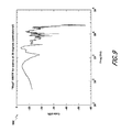
- FIGS. 8 and 9 show example real ipsilateral and contralateral HRTFs for a sound source at 30 degrees, respectively.
- FIGS. 10 and 11 show example modeled ipsilateral and contralateral HRTFs for a sound source at 30 degrees, respectively.
- the contrast between the example real HRTFs and the example modeled HRTFs is strong, with the real HRTFs having more and deeper peaks and valleys than the modeled HRTFs.
- the modeled ipsilateral HRTF in FIG. 10 has a generally upward trend as frequency increases, while the real ipsilateral HRTF in FIG.
- the real contralateral HRTF in FIG. 9 and the modeled contralateral HRTF in FIG. 11 both have a downward trend, but the peaks and valleys of the real contralateral HRTF are deeper and greater in number than with the modeled contralateral HRTF. Further, differences in starting and ending (as well as other) gain values also exist between the real and modeled HRTFs in FIGS. 9 through 11 , as is apparent from the FIGURES.
- FIGS. 12 through 15 Similar insights may be gained by comparing the real and modeled HRTFs shown in FIGS. 12 through 15 .
- FIGS. 12 and 13 show example real ipsilateral and contralateral HRTFs for a sound source at 90 degrees
- FIGS. 14 and 15 show example modeled ipsilateral and contralateral HRTFs for a sound source at 90 degrees, respectively.
- the modeled HRTFs in FIGS. 14 and 15 manifest more roundedness, averaging, or modeling than the real HRTFs in FIGS. 12 and 13 .
- starting and ending gain values differ.
- the HRTFs (or HRIR equivalents) shown in FIGS. 8 through 15 may be used as example filters for any of the HRTFs (or HRIRs) described above. However, the example HRTFs shown represent responses associated with a single room, and other HRTFs may be used instead for other rooms.
- the system may also store multiple different HRTFs for multiple different rooms and provide a user interface that enables a user to select an HRTF for a desired room.
- embodiments described herein can facilitate providing listeners who are used to an in-head listening experience of traditional headphones with a more out-of-head listening experience.
- this out-of-head listening experience may be tempered so as to be less out-of-head than a full out-of-head virtualization approach that might be appreciated by listeners who prefer a stereo loudspeaker experience.
- Parameters of the virtualization approaches described herein, including any of the gain parameters described above, may be varied to adjust between a full out-of-head experience and a fully (or partially) in-head experience.
- additional channels may be added to any of the systems described above.
- Providing additional channels can facilitate smoother panning transitions from one virtual speaker location to another.
- two additional channels can be added to FIG. 5 or 7 to create 7 channels to which a virtualization filter (with an appropriate HRTF) may each be applied.
- FIGS. 5 and 7 include filters for simulating front and side speakers, and the two new channels could be filtered to create two intermediate virtual speakers, one on each side of the listener's head and between the front and side channels. Panning can then be performed from front to intermediate to side speakers and vice versa.
- Any number of channels can be included in any of the systems described above to pan in any virtual direction around a listener's head.
Abstract
Description
Claims (19)
Priority Applications (1)
| Application Number | Priority Date | Filing Date | Title |
|---|---|---|---|
| US14/201,655 US9794715B2 (en) | 2013-03-13 | 2014-03-07 | System and methods for processing stereo audio content |
Applications Claiming Priority (2)
| Application Number | Priority Date | Filing Date | Title |
|---|---|---|---|
| US201361779941P | 2013-03-13 | 2013-03-13 | |
| US14/201,655 US9794715B2 (en) | 2013-03-13 | 2014-03-07 | System and methods for processing stereo audio content |
Publications (2)
| Publication Number | Publication Date |
|---|---|
| US20140270185A1 US20140270185A1 (en) | 2014-09-18 |
| US9794715B2 true US9794715B2 (en) | 2017-10-17 |
Family
ID=50397306
Family Applications (1)
| Application Number | Title | Priority Date | Filing Date |
|---|---|---|---|
| US14/201,655 Active 2035-01-02 US9794715B2 (en) | 2013-03-13 | 2014-03-07 | System and methods for processing stereo audio content |
Country Status (2)
| Country | Link |
|---|---|
| US (1) | US9794715B2 (en) |
| WO (1) | WO2014164361A1 (en) |
Cited By (1)
| Publication number | Priority date | Publication date | Assignee | Title |
|---|---|---|---|---|
| US20170154636A1 (en) * | 2014-12-12 | 2017-06-01 | Huawei Technologies Co., Ltd. | Signal processing apparatus for enhancing a voice component within a multi-channel audio signal |
Families Citing this family (14)
| Publication number | Priority date | Publication date | Assignee | Title |
|---|---|---|---|---|
| CN104956689B (en) | 2012-11-30 | 2017-07-04 | Dts(英属维尔京群岛)有限公司 | For the method and apparatus of personalized audio virtualization |
| WO2015048551A2 (en) * | 2013-09-27 | 2015-04-02 | Sony Computer Entertainment Inc. | Method of improving externalization of virtual surround sound |
| WO2016054098A1 (en) * | 2014-09-30 | 2016-04-07 | Nunntawi Dynamics Llc | Method for creating a virtual acoustic stereo system with an undistorted acoustic center |
| US10306392B2 (en) | 2015-11-03 | 2019-05-28 | Dolby Laboratories Licensing Corporation | Content-adaptive surround sound virtualization |
| JP2019518373A (en) | 2016-05-06 | 2019-06-27 | ディーティーエス・インコーポレイテッドDTS,Inc. | Immersive audio playback system |
| EP3373595A1 (en) | 2017-03-07 | 2018-09-12 | Thomson Licensing | Sound rendering with home cinema system and television |
| US10979844B2 (en) * | 2017-03-08 | 2021-04-13 | Dts, Inc. | Distributed audio virtualization systems |
| US10623883B2 (en) * | 2017-04-26 | 2020-04-14 | Hewlett-Packard Development Company, L.P. | Matrix decomposition of audio signal processing filters for spatial rendering |
| US10841726B2 (en) * | 2017-04-28 | 2020-11-17 | Hewlett-Packard Development Company, L.P. | Immersive audio rendering |
| JP7243052B2 (en) * | 2018-06-25 | 2023-03-22 | カシオ計算機株式会社 | Audio extraction device, audio playback device, audio extraction method, audio playback method, machine learning method and program |
| JP2021184509A (en) | 2018-08-29 | 2021-12-02 | ソニーグループ株式会社 | Signal processing device, signal processing method, and program |
| GB2584630A (en) * | 2019-05-29 | 2020-12-16 | Nokia Technologies Oy | Audio processing |
| CN111031467A (en) * | 2019-12-27 | 2020-04-17 | 中航华东光电(上海)有限公司 | Method for enhancing front and back directions of hrir |
| WO2023059838A1 (en) * | 2021-10-08 | 2023-04-13 | Dolby Laboratories Licensing Corporation | Headtracking adjusted binaural audio |
Citations (160)
| Publication number | Priority date | Publication date | Assignee | Title |
|---|---|---|---|---|
| US2511482A (en) | 1943-09-17 | 1950-06-13 | Sonotone Corp | Method of testing hearing |
| US3745674A (en) | 1972-02-03 | 1973-07-17 | R Thompson | Hearing tester |
| US3808354A (en) | 1972-12-13 | 1974-04-30 | Audiometric Teleprocessing Inc | Computer controlled method and system for audiometric screening |
| US3809811A (en) | 1972-08-10 | 1974-05-07 | Univ Sherbrooke | System for conducting automatically an audiometric test |
| US4107465A (en) | 1977-12-22 | 1978-08-15 | Centre De Recherche Industrielle Du Quebec | Automatic audiometer system |
| US4284847A (en) | 1978-06-30 | 1981-08-18 | Richard Besserman | Audiometric testing, analyzing, and recording apparatus and method |
| US4476724A (en) | 1981-11-17 | 1984-10-16 | Robert Bosch Gmbh | Audiometer |
| US4862505A (en) | 1986-10-23 | 1989-08-29 | Keith William J | Audiometer with interactive graphic display for children |
| US4868880A (en) | 1988-06-01 | 1989-09-19 | Yale University | Method and device for compensating for partial hearing loss |
| US5033086A (en) | 1988-10-24 | 1991-07-16 | AKG Akustische u. Kino-Gerate Gesellschaft m.b.H | Stereophonic binaural recording or reproduction method |
| US5438623A (en) | 1993-10-04 | 1995-08-01 | The United States Of America As Represented By The Administrator Of National Aeronautics And Space Administration | Multi-channel spatialization system for audio signals |
| US5579396A (en) | 1993-07-30 | 1996-11-26 | Victor Company Of Japan, Ltd. | Surround signal processing apparatus |
| WO1997025834A2 (en) | 1996-01-04 | 1997-07-17 | Virtual Listening Systems, Inc. | Method and device for processing a multi-channel signal for use with a headphone |
| US5737389A (en) | 1995-12-18 | 1998-04-07 | At&T Corp. | Technique for determining a compression ratio for use in processing audio signals within a telecommunications system |
| US5785661A (en) | 1994-08-17 | 1998-07-28 | Decibel Instruments, Inc. | Highly configurable hearing aid |
| US5825894A (en) | 1994-08-17 | 1998-10-20 | Decibel Instruments, Inc. | Spatialization for hearing evaluation |
| US5870481A (en) | 1996-09-25 | 1999-02-09 | Qsound Labs, Inc. | Method and apparatus for localization enhancement in hearing aids |
| US5912976A (en) | 1996-11-07 | 1999-06-15 | Srs Labs, Inc. | Multi-channel audio enhancement system for use in recording and playback and methods for providing same |
| US6086541A (en) | 1998-12-22 | 2000-07-11 | Rho; Yunsung | Method for testing hearing ability by using ARS (automatic voice response system) run by a computer, a program therefor and a noise blocker |
| US6109107A (en) | 1997-05-07 | 2000-08-29 | Scientific Learning Corporation | Method and apparatus for diagnosing and remediating language-based learning impairments |
| US6144747A (en) | 1997-04-02 | 2000-11-07 | Sonics Associates, Inc. | Head mounted surround sound system |
| US6212496B1 (en) | 1998-10-13 | 2001-04-03 | Denso Corporation, Ltd. | Customizing audio output to a user's hearing in a digital telephone |
| EP1089526A2 (en) | 1999-08-30 | 2001-04-04 | Lucent Technologies Inc. | Telephone with sound customizable to audiological profile of user |
| WO2001024576A1 (en) | 1999-09-28 | 2001-04-05 | Sound Id | Producing and storing hearing profiles and customized audio data based |
| US6319207B1 (en) | 2000-03-13 | 2001-11-20 | Sharmala Naidoo | Internet platform with screening test for hearing loss and for providing related health services |
| US6322521B1 (en) | 2000-01-24 | 2001-11-27 | Audia Technology, Inc. | Method and system for on-line hearing examination and correction |
| US6343131B1 (en) | 1997-10-20 | 2002-01-29 | Nokia Oyj | Method and a system for processing a virtual acoustic environment |
| US6379314B1 (en) | 2000-06-19 | 2002-04-30 | Health Performance, Inc. | Internet system for testing hearing |
| US20020068986A1 (en) | 1999-12-01 | 2002-06-06 | Ali Mouline | Adaptation of audio data files based on personal hearing profiles |
| US20020076072A1 (en) | 1999-04-26 | 2002-06-20 | Cornelisse Leonard E. | Software implemented loudness normalization for a digital hearing aid |
| US6428485B1 (en) | 1999-07-02 | 2002-08-06 | Gye-Won Sim | Method for testing hearing ability by using internet and recording medium on which the method therefor is recorded |
| US20030028385A1 (en) | 2001-06-30 | 2003-02-06 | Athena Christodoulou | Audio reproduction and personal audio profile gathering apparatus and method |
| US6522988B1 (en) | 2000-01-24 | 2003-02-18 | Audia Technology, Inc. | Method and system for on-line hearing examination using calibrated local machine |
| US20030073926A1 (en) | 2001-10-11 | 2003-04-17 | Johansen Benny B. | Method for setting volume and/or balance controls during a hearing test |
| US20030073927A1 (en) | 2001-10-11 | 2003-04-17 | Johansen Benny B. | Method for muting and/or un-muting of audio sources during a hearing test |
| US20030070485A1 (en) | 2001-10-11 | 2003-04-17 | Johansen Benny B. | Method for setting tone controls during a hearing test |
| US20030072455A1 (en) | 2001-10-11 | 2003-04-17 | Johansen Benny B. | Method and system for generating audio streams during a hearing test |
| US20030101215A1 (en) | 2001-11-27 | 2003-05-29 | Sunil Puria | Method for using sub-stimuli to reduce audio distortion in digitally generated stimuli during a hearing test |
| US6582378B1 (en) | 1999-09-29 | 2003-06-24 | Rion Co., Ltd. | Method of measuring frequency selectivity, and method and apparatus for estimating auditory filter shape by a frequency selectivity measurement method |
| US6584440B2 (en) | 2001-02-02 | 2003-06-24 | Wisconsin Alumni Research Foundation | Method and system for rapid and reliable testing of speech intelligibility in children |
| US20030123676A1 (en) | 2001-03-22 | 2003-07-03 | Schobben Daniel Willem Elisabeth | Method of deriving a head-related transfer function |
| US6644120B1 (en) | 1996-04-29 | 2003-11-11 | Bernafon, Inc. | Multimedia feature for diagnostic instrumentation |
| US20030223603A1 (en) | 2002-05-28 | 2003-12-04 | Beckman Kenneth Oren | Sound space replication |
| US20040049125A1 (en) | 2002-08-08 | 2004-03-11 | Norio Nakamura | Mobile terminal and mobile audiometer system |
| US6707918B1 (en) | 1998-03-31 | 2004-03-16 | Lake Technology Limited | Formulation of complex room impulse responses from 3-D audio information |
| US6724862B1 (en) | 2002-01-15 | 2004-04-20 | Cisco Technology, Inc. | Method and apparatus for customizing a device based on a frequency response for a hearing-impaired user |
| WO2004039126A2 (en) | 2002-10-25 | 2004-05-06 | Motorola Inc | Mobile radio communications device and method for adjusting audio characteristics |
| US6741706B1 (en) | 1998-03-25 | 2004-05-25 | Lake Technology Limited | Audio signal processing method and apparatus |
| US6801627B1 (en) | 1998-09-30 | 2004-10-05 | Openheart, Ltd. | Method for localization of an acoustic image out of man's head in hearing a reproduced sound via a headphone |
| US6813490B1 (en) | 1999-12-17 | 2004-11-02 | Nokia Corporation | Mobile station with audio signal adaptation to hearing characteristics of the user |
| WO2004104761A2 (en) | 2003-05-15 | 2004-12-02 | Tympany, Inc. | User interface for automated diagnostic hearing test |
| US6829361B2 (en) | 1999-12-24 | 2004-12-07 | Koninklijke Philips Electronics N.V. | Headphones with integrated microphones |
| US6840908B2 (en) | 2001-10-12 | 2005-01-11 | Sound Id | System and method for remotely administered, interactive hearing tests |
| US20050124375A1 (en) | 2002-03-12 | 2005-06-09 | Janusz Nowosielski | Multifunctional mobile phone for medical diagnosis and rehabilitation |
| US20050135644A1 (en) | 2003-12-23 | 2005-06-23 | Yingyong Qi | Digital cell phone with hearing aid functionality |
| US6913578B2 (en) | 2001-05-03 | 2005-07-05 | Apherma Corporation | Method for customizing audio systems for hearing impaired |
| US6928179B1 (en) | 1999-09-29 | 2005-08-09 | Sony Corporation | Audio processing apparatus |
| US6970569B1 (en) | 1998-10-30 | 2005-11-29 | Sony Corporation | Audio processing apparatus and audio reproducing method |
| WO2006002036A2 (en) | 2004-06-15 | 2006-01-05 | Johnson & Johnson Consumer Companies, Inc. | Audiometer instrument computer control system and method of use |
| WO2006007632A1 (en) | 2004-07-16 | 2006-01-26 | Era Centre Pty Ltd | A method for diagnostic home testing of hearing impairment, and related developmental problems in infants, toddlers, and children |
| US20060045281A1 (en) | 2004-08-27 | 2006-03-02 | Motorola, Inc. | Parameter adjustment in audio devices |
| US20060083394A1 (en) * | 2004-10-14 | 2006-04-20 | Mcgrath David S | Head related transfer functions for panned stereo audio content |
| US7042986B1 (en) | 2002-09-12 | 2006-05-09 | Plantronics, Inc. | DSP-enabled amplified telephone with digital audio processing |
| US7048692B2 (en) | 2002-01-22 | 2006-05-23 | Rion Co., Ltd. | Method and apparatus for estimating auditory filter shape |
| US20060215844A1 (en) | 2005-03-16 | 2006-09-28 | Voss Susan E | Method and device to optimize an audio sound field for normal and hearing-impaired listeners |
| US7133730B1 (en) | 1999-06-15 | 2006-11-07 | Yamaha Corporation | Audio apparatus, controller, audio system, and method of controlling audio apparatus |
| US7136492B2 (en) | 2002-07-11 | 2006-11-14 | Phonak Ag | Visual or audio playback of an audiogram |
| US7143031B1 (en) | 2001-12-18 | 2006-11-28 | The United States Of America As Represented By The Secretary Of The Army | Determining speech intelligibility |
| US7149684B1 (en) | 2001-12-18 | 2006-12-12 | The United States Of America As Represented By The Secretary Of The Army | Determining speech reception threshold |
| US7152082B2 (en) | 2000-08-14 | 2006-12-19 | Dolby Laboratories Licensing Corporation | Audio frequency response processing system |
| WO2006136174A2 (en) | 2005-06-24 | 2006-12-28 | Microsound A/S | Methods and systems for assessing hearing ability |
| US20070003077A1 (en) | 2002-12-09 | 2007-01-04 | Pedersen Soren L | Method of fitting portable communication device to a hearing impaired user |
| US7162047B2 (en) | 2002-03-18 | 2007-01-09 | Sony Corporation | Audio reproducing apparatus |
| US7167571B2 (en) | 2002-03-04 | 2007-01-23 | Lenovo Singapore Pte. Ltd | Automatic audio adjustment system based upon a user's auditory profile |
| US7181297B1 (en) | 1999-09-28 | 2007-02-20 | Sound Id | System and method for delivering customized audio data |
| US7184557B2 (en) | 2005-03-03 | 2007-02-27 | William Berson | Methods and apparatuses for recording and playing back audio signals |
| US7190795B2 (en) | 2003-10-08 | 2007-03-13 | Henry Simon | Hearing adjustment appliance for electronic audio equipment |
| US20070071263A1 (en) | 2005-09-26 | 2007-03-29 | Siemens Audiologische Technik Gmbh | Individually adjustable hearing apparatus |
| US7206416B2 (en) | 2003-08-01 | 2007-04-17 | University Of Florida Research Foundation, Inc. | Speech-based optimization of digital hearing devices |
| US7221765B2 (en) | 2002-04-12 | 2007-05-22 | Siemens Audiologische Technik Gmbh | System and method for individualized training of hearing aid users |
| US20070129649A1 (en) | 2005-08-31 | 2007-06-07 | Tympany, Inc. | Stenger Screening in Automated Diagnostic Hearing Test |
| US20070189545A1 (en) | 2006-01-30 | 2007-08-16 | Siemens Audiologische Technik Gmbh | Audiometer |
| US20080002845A1 (en) | 2005-02-17 | 2008-01-03 | Shunsaku Imaki | Auditory Head Outside Lateralization Apparatus and Auditory Head Outside Lateralization Method |
| US20080008328A1 (en) | 2006-07-06 | 2008-01-10 | Sony Ericsson Mobile Communications Ab | Audio processing in communication terminals |
| US7330552B1 (en) | 2003-12-19 | 2008-02-12 | Lamance Andrew | Multiple positional channels from a conventional stereo signal pair |
| US7333863B1 (en) | 1997-05-05 | 2008-02-19 | Warner Music Group, Inc. | Recording and playback control system |
| US20080049946A1 (en) | 2006-08-22 | 2008-02-28 | Phonak Ag | Self-paced in-situ audiometry |
| US7366307B2 (en) | 2002-10-11 | 2008-04-29 | Micro Ear Technology, Inc. | Programmable interface for fitting hearing devices |
| US7386140B2 (en) | 2002-10-23 | 2008-06-10 | Matsushita Electric Industrial Co., Ltd. | Audio information transforming method, audio information transforming program, and audio information transforming device |
| US20080167575A1 (en) | 2004-06-14 | 2008-07-10 | Johnson & Johnson Consumer Companies, Inc. | Audiologist Equipment Interface User Database For Providing Aural Rehabilitation Of Hearing Loss Across Multiple Dimensions Of Hearing |
| US7440575B2 (en) | 2002-11-22 | 2008-10-21 | Nokia Corporation | Equalization of the output in a stereo widening network |
| US20080269636A1 (en) | 2004-06-14 | 2008-10-30 | Johnson & Johnson Consumer Companies, Inc. | System for and Method of Conveniently and Automatically Testing the Hearing of a Person |
| US20080279401A1 (en) | 2007-05-07 | 2008-11-13 | Sunil Bharitkar | Stereo expansion with binaural modeling |
| US20080316879A1 (en) | 2004-07-14 | 2008-12-25 | Sony Corporation | Recording Medium, Recording Apparatus and Method, Data Processing Apparatus and Method and Data Outputting Apparatus |
| US20090013787A1 (en) | 2004-04-08 | 2009-01-15 | Philip Stuart Esnouf | Hearing testing device |
| US7529545B2 (en) | 2001-09-20 | 2009-05-05 | Sound Id | Sound enhancement for mobile phones and others products producing personalized audio for users |
| US20090116657A1 (en) | 2007-11-06 | 2009-05-07 | Starkey Laboratories, Inc. | Simulated surround sound hearing aid fitting system |
| US7536021B2 (en) | 1997-09-16 | 2009-05-19 | Dolby Laboratories Licensing Corporation | Utilization of filtering effects in stereo headphone devices to enhance spatialization of source around a listener |
| US7564979B2 (en) | 2005-01-08 | 2009-07-21 | Robert Swartz | Listener specific audio reproduction system |
| US20090268919A1 (en) | 2008-04-25 | 2009-10-29 | Samsung Electronics Co., Ltd | Method and apparatus to measure hearing ability of user of mobile device |
| EP2124479A1 (en) | 2008-05-16 | 2009-11-25 | Alcatel Lucent | Correction device for an audio reproducing device |
| WO2010017156A1 (en) | 2008-08-04 | 2010-02-11 | Audigence, Inc. | Automatic performance optimization for perceptual devices |
| US20100056950A1 (en) | 2008-08-29 | 2010-03-04 | University Of Florida Research Foundation, Inc. | System and methods for creating reduced test sets used in assessing subject response to stimuli |
| US20100056951A1 (en) | 2008-08-29 | 2010-03-04 | University Of Florida Research Foundation, Inc. | System and methods of subject classification based on assessed hearing capabilities |
| US7680465B2 (en) | 2006-07-31 | 2010-03-16 | Broadcom Corporation | Sound enhancement for audio devices based on user-specific audio processing parameters |
| US20100098262A1 (en) | 2008-10-17 | 2010-04-22 | Froehlich Matthias | Method and hearing device for parameter adaptation by determining a speech intelligibility threshold |
| US7715575B1 (en) | 2005-02-28 | 2010-05-11 | Texas Instruments Incorporated | Room impulse response |
| US20100119093A1 (en) | 2008-11-13 | 2010-05-13 | Michael Uzuanis | Personal listening device with automatic sound equalization and hearing testing |
| US20100137739A1 (en) | 2008-08-20 | 2010-06-03 | Lee Sang-Min | Method and device for hearing test |
| US20100166238A1 (en) | 2008-12-29 | 2010-07-01 | Samsung Electronics Co., Ltd. | Surround sound virtualization apparatus and method |
| US20100183161A1 (en) | 2007-07-06 | 2010-07-22 | Phonak Ag | Method and arrangement for training hearing system users |
| US20100191143A1 (en) | 2006-04-04 | 2010-07-29 | Cleartone Technologies Limited | Calibrated digital headset and audiometric test methods therewith |
| US7773755B2 (en) | 2004-08-27 | 2010-08-10 | Sony Corporation | Reproduction apparatus and reproduction system |
| US20100215199A1 (en) | 2007-10-03 | 2010-08-26 | Koninklijke Philips Electronics N.V. | Method for headphone reproduction, a headphone reproduction system, a computer program product |
| US7793545B2 (en) | 2007-10-04 | 2010-09-14 | Benson Medical Instruments Company | Audiometer with interchangeable transducer |
| US20100272297A1 (en) | 2007-11-14 | 2010-10-28 | Phonak Ag | Method and arrangement for fitting a hearing system |
| US7826630B2 (en) | 2004-06-29 | 2010-11-02 | Sony Corporation | Sound image localization apparatus |
| WO2010139760A2 (en) | 2009-06-04 | 2010-12-09 | Syddansk Universitet | System and method for conducting an alternative forced choice hearing test |
| US20100310101A1 (en) | 2009-06-09 | 2010-12-09 | Dean Robert Gary Anderson | Method and apparatus for directional acoustic fitting of hearing aids |
| US20100316227A1 (en) | 2009-06-10 | 2010-12-16 | Siemens Medical Instruments Pte. Ltd. | Method for determining a frequency response of a hearing apparatus and associated hearing apparatus |
| US20100329490A1 (en) | 2008-02-20 | 2010-12-30 | Koninklijke Philips Electronics N.V. | Audio device and method of operation therefor |
| US20110009771A1 (en) | 2008-02-29 | 2011-01-13 | France Telecom | Method and device for determining transfer functions of the hrtf type |
| US7876908B2 (en) | 2004-12-29 | 2011-01-25 | Phonak Ag | Process for the visualization of hearing ability |
| WO2011014906A1 (en) | 2009-08-02 | 2011-02-10 | Peter Blamey | Fitting of sound processors using improved sounds |
| US20110046511A1 (en) | 2009-08-18 | 2011-02-24 | Samsung Electronics Co., Ltd. | Portable sound source playing apparatus for testing hearing ability and method of testing hearing ability using the apparatus |
| WO2011026908A1 (en) | 2009-09-03 | 2011-03-10 | National Digital Research Centre | An auditory test and compensation method |
| US20110075853A1 (en) | 2009-07-23 | 2011-03-31 | Dean Robert Gary Anderson | Method of deriving individualized gain compensation curves for hearing aid fitting |
| WO2011039413A1 (en) | 2009-09-30 | 2011-04-07 | Nokia Corporation | An apparatus |
| US20110091046A1 (en) * | 2006-06-02 | 2011-04-21 | Lars Villemoes | Binaural multi-channel decoder in the context of non-energy-conserving upmix rules |
| US7933419B2 (en) | 2005-10-05 | 2011-04-26 | Phonak Ag | In-situ-fitted hearing device |
| US7936888B2 (en) | 2004-12-23 | 2011-05-03 | Kwon Dae-Hoon | Equalization apparatus and method based on audiogram |
| US7936887B2 (en) | 2004-09-01 | 2011-05-03 | Smyth Research Llc | Personalized headphone virtualization |
| US20110106508A1 (en) | 2007-08-29 | 2011-05-05 | Phonak Ag | Fitting procedure for hearing devices and corresponding hearing device |
| US7949141B2 (en) | 2003-11-12 | 2011-05-24 | Dolby Laboratories Licensing Corporation | Processing audio signals with head related transfer function filters and a reverberator |
| US7978866B2 (en) | 2005-11-18 | 2011-07-12 | Sony Corporation | Acoustics correcting apparatus |
| US20110190658A1 (en) | 2010-02-02 | 2011-08-04 | Samsung Electronics Co., Ltd. | Portable sound source reproducing apparatus for testing hearing ability and method using the same |
| US20110211702A1 (en) * | 2008-07-31 | 2011-09-01 | Mundt Harald | Signal Generation for Binaural Signals |
| US20110219879A1 (en) | 2010-03-09 | 2011-09-15 | Siemens Medical Instruments Pte. Ltd. | Hearing-test method |
| US8059833B2 (en) | 2004-12-28 | 2011-11-15 | Samsung Electronics Co., Ltd. | Method of compensating audio frequency response characteristics in real-time and a sound system using the same |
| US20110280409A1 (en) | 2010-05-12 | 2011-11-17 | Sound Id | Personalized Hearing Profile Generation with Real-Time Feedback |
| US8064624B2 (en) | 2007-07-19 | 2011-11-22 | Fraunhofer-Gesellschaft Zur Foerderung Der Angewandten Forschung E.V. | Method and apparatus for generating a stereo signal with enhanced perceptual quality |
| US20110305358A1 (en) | 2010-06-14 | 2011-12-15 | Sony Corporation | Head related transfer function generation apparatus, head related transfer function generation method, and sound signal processing apparatus |
| US8112166B2 (en) | 2007-01-04 | 2012-02-07 | Sound Id | Personalized sound system hearing profile selection process |
| WO2012016527A1 (en) | 2010-08-05 | 2012-02-09 | The Chinese University Of Hong Kong | Method and system for self-managed sound enhancement |
| US20120051569A1 (en) | 2009-02-16 | 2012-03-01 | Peter John Blamey | Automated fitting of hearing devices |
| US8130989B2 (en) | 2006-09-07 | 2012-03-06 | Siemens Audiologische Technik Gmbh | Gender-specific hearing device adjustment |
| US20120057715A1 (en) | 2010-09-08 | 2012-03-08 | Johnston James D | Spatial audio encoding and reproduction |
| US8135138B2 (en) | 2007-08-29 | 2012-03-13 | University Of California, Berkeley | Hearing aid fitting procedure and processing based on subjective space representation |
| US20120063616A1 (en) | 2010-09-10 | 2012-03-15 | Martin Walsh | Dynamic compensation of audio signals for improved perceived spectral imbalances |
| US8144902B2 (en) | 2007-11-27 | 2012-03-27 | Microsoft Corporation | Stereo image widening |
| US8160281B2 (en) | 2004-09-08 | 2012-04-17 | Samsung Electronics Co., Ltd. | Sound reproducing apparatus and sound reproducing method |
| US8161816B2 (en) | 2009-11-03 | 2012-04-24 | Matthew Beck | Hearing test method and apparatus |
| US8166312B2 (en) | 2007-09-05 | 2012-04-24 | Phonak Ag | Method of individually fitting a hearing device or hearing aid |
| US20120099733A1 (en) | 2010-10-20 | 2012-04-26 | Srs Labs, Inc. | Audio adjustment system |
| US8195453B2 (en) | 2007-09-13 | 2012-06-05 | Qnx Software Systems Limited | Distributed intelligibility testing system |
| US8196470B2 (en) | 2006-03-01 | 2012-06-12 | 3M Innovative Properties Company | Wireless interface for audiometers |
| US20120157876A1 (en) | 2010-12-21 | 2012-06-21 | Samsung Electronics Co., Ltd. | Hearing test method and apparatus |
| US8284946B2 (en) | 2006-03-07 | 2012-10-09 | Samsung Electronics Co., Ltd. | Binaural decoder to output spatial stereo sound and a decoding method thereof |
| US20120288124A1 (en) | 2011-05-09 | 2012-11-15 | Dts, Inc. | Room characterization and correction for multi-channel audio |
| US8340303B2 (en) | 2005-10-25 | 2012-12-25 | Samsung Electronics Co., Ltd. | Method and apparatus to generate spatial stereo sound |
Family Cites Families (1)
| Publication number | Priority date | Publication date | Assignee | Title |
|---|---|---|---|---|
| US5956674A (en) | 1995-12-01 | 1999-09-21 | Digital Theater Systems, Inc. | Multi-channel predictive subband audio coder using psychoacoustic adaptive bit allocation in frequency, time and over the multiple channels |
-
2014
- 2014-03-07 WO PCT/US2014/022131 patent/WO2014164361A1/en active Application Filing
- 2014-03-07 US US14/201,655 patent/US9794715B2/en active Active
Patent Citations (171)
| Publication number | Priority date | Publication date | Assignee | Title |
|---|---|---|---|---|
| US2511482A (en) | 1943-09-17 | 1950-06-13 | Sonotone Corp | Method of testing hearing |
| US3745674A (en) | 1972-02-03 | 1973-07-17 | R Thompson | Hearing tester |
| US3809811A (en) | 1972-08-10 | 1974-05-07 | Univ Sherbrooke | System for conducting automatically an audiometric test |
| US3808354A (en) | 1972-12-13 | 1974-04-30 | Audiometric Teleprocessing Inc | Computer controlled method and system for audiometric screening |
| US4107465A (en) | 1977-12-22 | 1978-08-15 | Centre De Recherche Industrielle Du Quebec | Automatic audiometer system |
| US4284847A (en) | 1978-06-30 | 1981-08-18 | Richard Besserman | Audiometric testing, analyzing, and recording apparatus and method |
| US4476724A (en) | 1981-11-17 | 1984-10-16 | Robert Bosch Gmbh | Audiometer |
| US4862505A (en) | 1986-10-23 | 1989-08-29 | Keith William J | Audiometer with interactive graphic display for children |
| US4868880A (en) | 1988-06-01 | 1989-09-19 | Yale University | Method and device for compensating for partial hearing loss |
| US5033086A (en) | 1988-10-24 | 1991-07-16 | AKG Akustische u. Kino-Gerate Gesellschaft m.b.H | Stereophonic binaural recording or reproduction method |
| US5579396A (en) | 1993-07-30 | 1996-11-26 | Victor Company Of Japan, Ltd. | Surround signal processing apparatus |
| US5438623A (en) | 1993-10-04 | 1995-08-01 | The United States Of America As Represented By The Administrator Of National Aeronautics And Space Administration | Multi-channel spatialization system for audio signals |
| US5785661A (en) | 1994-08-17 | 1998-07-28 | Decibel Instruments, Inc. | Highly configurable hearing aid |
| US5825894A (en) | 1994-08-17 | 1998-10-20 | Decibel Instruments, Inc. | Spatialization for hearing evaluation |
| US6167138A (en) | 1994-08-17 | 2000-12-26 | Decibel Instruments, Inc. | Spatialization for hearing evaluation |
| US5737389A (en) | 1995-12-18 | 1998-04-07 | At&T Corp. | Technique for determining a compression ratio for use in processing audio signals within a telecommunications system |
| WO1997025834A2 (en) | 1996-01-04 | 1997-07-17 | Virtual Listening Systems, Inc. | Method and device for processing a multi-channel signal for use with a headphone |
| US7210353B2 (en) | 1996-04-29 | 2007-05-01 | Diagnostic Group, Llc | Multimedia feature for diagnostic instrumentation |
| US6644120B1 (en) | 1996-04-29 | 2003-11-11 | Bernafon, Inc. | Multimedia feature for diagnostic instrumentation |
| US20050148900A1 (en) | 1996-04-29 | 2005-07-07 | Diagnostic Group, Llc | Method of obtaining data related to hearing ability with automatic delivery of corrective instructions |
| US20070204696A1 (en) | 1996-04-29 | 2007-09-06 | Diagnostic Group, Llc | Multimedia feature for diagnostic instrumentation |
| US5870481A (en) | 1996-09-25 | 1999-02-09 | Qsound Labs, Inc. | Method and apparatus for localization enhancement in hearing aids |
| US5912976A (en) | 1996-11-07 | 1999-06-15 | Srs Labs, Inc. | Multi-channel audio enhancement system for use in recording and playback and methods for providing same |
| US6144747A (en) | 1997-04-02 | 2000-11-07 | Sonics Associates, Inc. | Head mounted surround sound system |
| US7333863B1 (en) | 1997-05-05 | 2008-02-19 | Warner Music Group, Inc. | Recording and playback control system |
| US6109107A (en) | 1997-05-07 | 2000-08-29 | Scientific Learning Corporation | Method and apparatus for diagnosing and remediating language-based learning impairments |
| US6457362B1 (en) | 1997-05-07 | 2002-10-01 | Scientific Learning Corporation | Method and apparatus for diagnosing and remediating language-based learning impairments |
| US7536021B2 (en) | 1997-09-16 | 2009-05-19 | Dolby Laboratories Licensing Corporation | Utilization of filtering effects in stereo headphone devices to enhance spatialization of source around a listener |
| US7539319B2 (en) | 1997-09-16 | 2009-05-26 | Dolby Laboratories Licensing Corporation | Utilization of filtering effects in stereo headphone devices to enhance spatialization of source around a listener |
| US6343131B1 (en) | 1997-10-20 | 2002-01-29 | Nokia Oyj | Method and a system for processing a virtual acoustic environment |
| US6741706B1 (en) | 1998-03-25 | 2004-05-25 | Lake Technology Limited | Audio signal processing method and apparatus |
| US6707918B1 (en) | 1998-03-31 | 2004-03-16 | Lake Technology Limited | Formulation of complex room impulse responses from 3-D audio information |
| US6801627B1 (en) | 1998-09-30 | 2004-10-05 | Openheart, Ltd. | Method for localization of an acoustic image out of man's head in hearing a reproduced sound via a headphone |
| US6212496B1 (en) | 1998-10-13 | 2001-04-03 | Denso Corporation, Ltd. | Customizing audio output to a user's hearing in a digital telephone |
| US6970569B1 (en) | 1998-10-30 | 2005-11-29 | Sony Corporation | Audio processing apparatus and audio reproducing method |
| US6086541A (en) | 1998-12-22 | 2000-07-11 | Rho; Yunsung | Method for testing hearing ability by using ARS (automatic voice response system) run by a computer, a program therefor and a noise blocker |
| US20020076072A1 (en) | 1999-04-26 | 2002-06-20 | Cornelisse Leonard E. | Software implemented loudness normalization for a digital hearing aid |
| US7133730B1 (en) | 1999-06-15 | 2006-11-07 | Yamaha Corporation | Audio apparatus, controller, audio system, and method of controlling audio apparatus |
| US6428485B1 (en) | 1999-07-02 | 2002-08-06 | Gye-Won Sim | Method for testing hearing ability by using internet and recording medium on which the method therefor is recorded |
| EP1089526A2 (en) | 1999-08-30 | 2001-04-04 | Lucent Technologies Inc. | Telephone with sound customizable to audiological profile of user |
| US7181297B1 (en) | 1999-09-28 | 2007-02-20 | Sound Id | System and method for delivering customized audio data |
| WO2001024576A1 (en) | 1999-09-28 | 2001-04-05 | Sound Id | Producing and storing hearing profiles and customized audio data based |
| US6928179B1 (en) | 1999-09-29 | 2005-08-09 | Sony Corporation | Audio processing apparatus |
| US6582378B1 (en) | 1999-09-29 | 2003-06-24 | Rion Co., Ltd. | Method of measuring frequency selectivity, and method and apparatus for estimating auditory filter shape by a frequency selectivity measurement method |
| US20020068986A1 (en) | 1999-12-01 | 2002-06-06 | Ali Mouline | Adaptation of audio data files based on personal hearing profiles |
| US6813490B1 (en) | 1999-12-17 | 2004-11-02 | Nokia Corporation | Mobile station with audio signal adaptation to hearing characteristics of the user |
| US6829361B2 (en) | 1999-12-24 | 2004-12-07 | Koninklijke Philips Electronics N.V. | Headphones with integrated microphones |
| US6522988B1 (en) | 2000-01-24 | 2003-02-18 | Audia Technology, Inc. | Method and system for on-line hearing examination using calibrated local machine |
| US6322521B1 (en) | 2000-01-24 | 2001-11-27 | Audia Technology, Inc. | Method and system for on-line hearing examination and correction |
| US6319207B1 (en) | 2000-03-13 | 2001-11-20 | Sharmala Naidoo | Internet platform with screening test for hearing loss and for providing related health services |
| US6379314B1 (en) | 2000-06-19 | 2002-04-30 | Health Performance, Inc. | Internet system for testing hearing |
| US8009836B2 (en) | 2000-08-14 | 2011-08-30 | Dolby Laboratories Licensing Corporation | Audio frequency response processing system |
| US7152082B2 (en) | 2000-08-14 | 2006-12-19 | Dolby Laboratories Licensing Corporation | Audio frequency response processing system |
| US6584440B2 (en) | 2001-02-02 | 2003-06-24 | Wisconsin Alumni Research Foundation | Method and system for rapid and reliable testing of speech intelligibility in children |
| US20030123676A1 (en) | 2001-03-22 | 2003-07-03 | Schobben Daniel Willem Elisabeth | Method of deriving a head-related transfer function |
| US6913578B2 (en) | 2001-05-03 | 2005-07-05 | Apherma Corporation | Method for customizing audio systems for hearing impaired |
| US20030028385A1 (en) | 2001-06-30 | 2003-02-06 | Athena Christodoulou | Audio reproduction and personal audio profile gathering apparatus and method |
| US7529545B2 (en) | 2001-09-20 | 2009-05-05 | Sound Id | Sound enhancement for mobile phones and others products producing personalized audio for users |
| US20030073927A1 (en) | 2001-10-11 | 2003-04-17 | Johansen Benny B. | Method for muting and/or un-muting of audio sources during a hearing test |
| US20030072455A1 (en) | 2001-10-11 | 2003-04-17 | Johansen Benny B. | Method and system for generating audio streams during a hearing test |
| US20030073926A1 (en) | 2001-10-11 | 2003-04-17 | Johansen Benny B. | Method for setting volume and/or balance controls during a hearing test |
| US20030070485A1 (en) | 2001-10-11 | 2003-04-17 | Johansen Benny B. | Method for setting tone controls during a hearing test |
| US6840908B2 (en) | 2001-10-12 | 2005-01-11 | Sound Id | System and method for remotely administered, interactive hearing tests |
| US20030101215A1 (en) | 2001-11-27 | 2003-05-29 | Sunil Puria | Method for using sub-stimuli to reduce audio distortion in digitally generated stimuli during a hearing test |
| US7143031B1 (en) | 2001-12-18 | 2006-11-28 | The United States Of America As Represented By The Secretary Of The Army | Determining speech intelligibility |
| US7149684B1 (en) | 2001-12-18 | 2006-12-12 | The United States Of America As Represented By The Secretary Of The Army | Determining speech reception threshold |
| US6724862B1 (en) | 2002-01-15 | 2004-04-20 | Cisco Technology, Inc. | Method and apparatus for customizing a device based on a frequency response for a hearing-impaired user |
| US7048692B2 (en) | 2002-01-22 | 2006-05-23 | Rion Co., Ltd. | Method and apparatus for estimating auditory filter shape |
| US7167571B2 (en) | 2002-03-04 | 2007-01-23 | Lenovo Singapore Pte. Ltd | Automatic audio adjustment system based upon a user's auditory profile |
| US20050124375A1 (en) | 2002-03-12 | 2005-06-09 | Janusz Nowosielski | Multifunctional mobile phone for medical diagnosis and rehabilitation |
| US7162047B2 (en) | 2002-03-18 | 2007-01-09 | Sony Corporation | Audio reproducing apparatus |
| US7221765B2 (en) | 2002-04-12 | 2007-05-22 | Siemens Audiologische Technik Gmbh | System and method for individualized training of hearing aid users |
| US20090156959A1 (en) | 2002-05-23 | 2009-06-18 | Tympany, Llc | Stenger screening in automated diagnostic hearing test |
| US20030223603A1 (en) | 2002-05-28 | 2003-12-04 | Beckman Kenneth Oren | Sound space replication |
| US7136492B2 (en) | 2002-07-11 | 2006-11-14 | Phonak Ag | Visual or audio playback of an audiogram |
| US20040049125A1 (en) | 2002-08-08 | 2004-03-11 | Norio Nakamura | Mobile terminal and mobile audiometer system |
| US7042986B1 (en) | 2002-09-12 | 2006-05-09 | Plantronics, Inc. | DSP-enabled amplified telephone with digital audio processing |
| US7366307B2 (en) | 2002-10-11 | 2008-04-29 | Micro Ear Technology, Inc. | Programmable interface for fitting hearing devices |
| US7386140B2 (en) | 2002-10-23 | 2008-06-10 | Matsushita Electric Industrial Co., Ltd. | Audio information transforming method, audio information transforming program, and audio information transforming device |
| WO2004039126A2 (en) | 2002-10-25 | 2004-05-06 | Motorola Inc | Mobile radio communications device and method for adjusting audio characteristics |
| US7440575B2 (en) | 2002-11-22 | 2008-10-21 | Nokia Corporation | Equalization of the output in a stereo widening network |
| US20070003077A1 (en) | 2002-12-09 | 2007-01-04 | Pedersen Soren L | Method of fitting portable communication device to a hearing impaired user |
| WO2004104761A2 (en) | 2003-05-15 | 2004-12-02 | Tympany, Inc. | User interface for automated diagnostic hearing test |
| US7206416B2 (en) | 2003-08-01 | 2007-04-17 | University Of Florida Research Foundation, Inc. | Speech-based optimization of digital hearing devices |
| US7190795B2 (en) | 2003-10-08 | 2007-03-13 | Henry Simon | Hearing adjustment appliance for electronic audio equipment |
| US7949141B2 (en) | 2003-11-12 | 2011-05-24 | Dolby Laboratories Licensing Corporation | Processing audio signals with head related transfer function filters and a reverberator |
| US7330552B1 (en) | 2003-12-19 | 2008-02-12 | Lamance Andrew | Multiple positional channels from a conventional stereo signal pair |
| US20050135644A1 (en) | 2003-12-23 | 2005-06-23 | Yingyong Qi | Digital cell phone with hearing aid functionality |
| US20090013787A1 (en) | 2004-04-08 | 2009-01-15 | Philip Stuart Esnouf | Hearing testing device |
| US20080269636A1 (en) | 2004-06-14 | 2008-10-30 | Johnson & Johnson Consumer Companies, Inc. | System for and Method of Conveniently and Automatically Testing the Hearing of a Person |
| US20080167575A1 (en) | 2004-06-14 | 2008-07-10 | Johnson & Johnson Consumer Companies, Inc. | Audiologist Equipment Interface User Database For Providing Aural Rehabilitation Of Hearing Loss Across Multiple Dimensions Of Hearing |
| WO2006002036A2 (en) | 2004-06-15 | 2006-01-05 | Johnson & Johnson Consumer Companies, Inc. | Audiometer instrument computer control system and method of use |
| US7826630B2 (en) | 2004-06-29 | 2010-11-02 | Sony Corporation | Sound image localization apparatus |
| US20080316879A1 (en) | 2004-07-14 | 2008-12-25 | Sony Corporation | Recording Medium, Recording Apparatus and Method, Data Processing Apparatus and Method and Data Outputting Apparatus |
| WO2006007632A1 (en) | 2004-07-16 | 2006-01-26 | Era Centre Pty Ltd | A method for diagnostic home testing of hearing impairment, and related developmental problems in infants, toddlers, and children |
| US20060045281A1 (en) | 2004-08-27 | 2006-03-02 | Motorola, Inc. | Parameter adjustment in audio devices |
| US7773755B2 (en) | 2004-08-27 | 2010-08-10 | Sony Corporation | Reproduction apparatus and reproduction system |
| US7936887B2 (en) | 2004-09-01 | 2011-05-03 | Smyth Research Llc | Personalized headphone virtualization |
| US8160281B2 (en) | 2004-09-08 | 2012-04-17 | Samsung Electronics Co., Ltd. | Sound reproducing apparatus and sound reproducing method |
| US20060083394A1 (en) * | 2004-10-14 | 2006-04-20 | Mcgrath David S | Head related transfer functions for panned stereo audio content |
| US7634092B2 (en) | 2004-10-14 | 2009-12-15 | Dolby Laboratories Licensing Corporation | Head related transfer functions for panned stereo audio content |
| US7936888B2 (en) | 2004-12-23 | 2011-05-03 | Kwon Dae-Hoon | Equalization apparatus and method based on audiogram |
| US8059833B2 (en) | 2004-12-28 | 2011-11-15 | Samsung Electronics Co., Ltd. | Method of compensating audio frequency response characteristics in real-time and a sound system using the same |
| US7876908B2 (en) | 2004-12-29 | 2011-01-25 | Phonak Ag | Process for the visualization of hearing ability |
| US7564979B2 (en) | 2005-01-08 | 2009-07-21 | Robert Swartz | Listener specific audio reproduction system |
| US20080002845A1 (en) | 2005-02-17 | 2008-01-03 | Shunsaku Imaki | Auditory Head Outside Lateralization Apparatus and Auditory Head Outside Lateralization Method |
| US7715575B1 (en) | 2005-02-28 | 2010-05-11 | Texas Instruments Incorporated | Room impulse response |
| US7184557B2 (en) | 2005-03-03 | 2007-02-27 | William Berson | Methods and apparatuses for recording and playing back audio signals |
| US20060215844A1 (en) | 2005-03-16 | 2006-09-28 | Voss Susan E | Method and device to optimize an audio sound field for normal and hearing-impaired listeners |
| WO2006136174A2 (en) | 2005-06-24 | 2006-12-28 | Microsound A/S | Methods and systems for assessing hearing ability |
| US20070129649A1 (en) | 2005-08-31 | 2007-06-07 | Tympany, Inc. | Stenger Screening in Automated Diagnostic Hearing Test |
| US20070071263A1 (en) | 2005-09-26 | 2007-03-29 | Siemens Audiologische Technik Gmbh | Individually adjustable hearing apparatus |
| US7933419B2 (en) | 2005-10-05 | 2011-04-26 | Phonak Ag | In-situ-fitted hearing device |
| US8340303B2 (en) | 2005-10-25 | 2012-12-25 | Samsung Electronics Co., Ltd. | Method and apparatus to generate spatial stereo sound |
| US7978866B2 (en) | 2005-11-18 | 2011-07-12 | Sony Corporation | Acoustics correcting apparatus |
| US20070189545A1 (en) | 2006-01-30 | 2007-08-16 | Siemens Audiologische Technik Gmbh | Audiometer |
| US8196470B2 (en) | 2006-03-01 | 2012-06-12 | 3M Innovative Properties Company | Wireless interface for audiometers |
| US8284946B2 (en) | 2006-03-07 | 2012-10-09 | Samsung Electronics Co., Ltd. | Binaural decoder to output spatial stereo sound and a decoding method thereof |
| US20100191143A1 (en) | 2006-04-04 | 2010-07-29 | Cleartone Technologies Limited | Calibrated digital headset and audiometric test methods therewith |
| US20110091046A1 (en) * | 2006-06-02 | 2011-04-21 | Lars Villemoes | Binaural multi-channel decoder in the context of non-energy-conserving upmix rules |
| US20080008328A1 (en) | 2006-07-06 | 2008-01-10 | Sony Ericsson Mobile Communications Ab | Audio processing in communication terminals |
| US7680465B2 (en) | 2006-07-31 | 2010-03-16 | Broadcom Corporation | Sound enhancement for audio devices based on user-specific audio processing parameters |
| US20080049946A1 (en) | 2006-08-22 | 2008-02-28 | Phonak Ag | Self-paced in-situ audiometry |
| US8130989B2 (en) | 2006-09-07 | 2012-03-06 | Siemens Audiologische Technik Gmbh | Gender-specific hearing device adjustment |
| US8112166B2 (en) | 2007-01-04 | 2012-02-07 | Sound Id | Personalized sound system hearing profile selection process |
| US20080279401A1 (en) | 2007-05-07 | 2008-11-13 | Sunil Bharitkar | Stereo expansion with binaural modeling |
| US20100183161A1 (en) | 2007-07-06 | 2010-07-22 | Phonak Ag | Method and arrangement for training hearing system users |
| US8064624B2 (en) | 2007-07-19 | 2011-11-22 | Fraunhofer-Gesellschaft Zur Foerderung Der Angewandten Forschung E.V. | Method and apparatus for generating a stereo signal with enhanced perceptual quality |
| US8135138B2 (en) | 2007-08-29 | 2012-03-13 | University Of California, Berkeley | Hearing aid fitting procedure and processing based on subjective space representation |
| US20110106508A1 (en) | 2007-08-29 | 2011-05-05 | Phonak Ag | Fitting procedure for hearing devices and corresponding hearing device |
| US20120134521A1 (en) | 2007-08-29 | 2012-05-31 | University Of California | Hearing aid fitting procedure and processing based on subjective space representation |
| US8166312B2 (en) | 2007-09-05 | 2012-04-24 | Phonak Ag | Method of individually fitting a hearing device or hearing aid |
| US8195453B2 (en) | 2007-09-13 | 2012-06-05 | Qnx Software Systems Limited | Distributed intelligibility testing system |
| US20100215199A1 (en) | 2007-10-03 | 2010-08-26 | Koninklijke Philips Electronics N.V. | Method for headphone reproduction, a headphone reproduction system, a computer program product |
| US7793545B2 (en) | 2007-10-04 | 2010-09-14 | Benson Medical Instruments Company | Audiometer with interchangeable transducer |
| US20090116657A1 (en) | 2007-11-06 | 2009-05-07 | Starkey Laboratories, Inc. | Simulated surround sound hearing aid fitting system |
| US20100272297A1 (en) | 2007-11-14 | 2010-10-28 | Phonak Ag | Method and arrangement for fitting a hearing system |
| US8144902B2 (en) | 2007-11-27 | 2012-03-27 | Microsoft Corporation | Stereo image widening |
| US20100329490A1 (en) | 2008-02-20 | 2010-12-30 | Koninklijke Philips Electronics N.V. | Audio device and method of operation therefor |
| US20110009771A1 (en) | 2008-02-29 | 2011-01-13 | France Telecom | Method and device for determining transfer functions of the hrtf type |
| US8358786B2 (en) | 2008-04-25 | 2013-01-22 | Samsung Electronics Co., Ltd. | Method and apparatus to measure hearing ability of user of mobile device |
| US20090268919A1 (en) | 2008-04-25 | 2009-10-29 | Samsung Electronics Co., Ltd | Method and apparatus to measure hearing ability of user of mobile device |
| EP2124479A1 (en) | 2008-05-16 | 2009-11-25 | Alcatel Lucent | Correction device for an audio reproducing device |
| US20110211702A1 (en) * | 2008-07-31 | 2011-09-01 | Mundt Harald | Signal Generation for Binaural Signals |
| WO2010017156A1 (en) | 2008-08-04 | 2010-02-11 | Audigence, Inc. | Automatic performance optimization for perceptual devices |
| US20100137739A1 (en) | 2008-08-20 | 2010-06-03 | Lee Sang-Min | Method and device for hearing test |
| US20100056951A1 (en) | 2008-08-29 | 2010-03-04 | University Of Florida Research Foundation, Inc. | System and methods of subject classification based on assessed hearing capabilities |
| US20100056950A1 (en) | 2008-08-29 | 2010-03-04 | University Of Florida Research Foundation, Inc. | System and methods for creating reduced test sets used in assessing subject response to stimuli |
| US20100098262A1 (en) | 2008-10-17 | 2010-04-22 | Froehlich Matthias | Method and hearing device for parameter adaptation by determining a speech intelligibility threshold |
| US20100119093A1 (en) | 2008-11-13 | 2010-05-13 | Michael Uzuanis | Personal listening device with automatic sound equalization and hearing testing |
| US20100166238A1 (en) | 2008-12-29 | 2010-07-01 | Samsung Electronics Co., Ltd. | Surround sound virtualization apparatus and method |
| US20120051569A1 (en) | 2009-02-16 | 2012-03-01 | Peter John Blamey | Automated fitting of hearing devices |
| WO2010139760A2 (en) | 2009-06-04 | 2010-12-09 | Syddansk Universitet | System and method for conducting an alternative forced choice hearing test |
| US20100310101A1 (en) | 2009-06-09 | 2010-12-09 | Dean Robert Gary Anderson | Method and apparatus for directional acoustic fitting of hearing aids |
| US20100316227A1 (en) | 2009-06-10 | 2010-12-16 | Siemens Medical Instruments Pte. Ltd. | Method for determining a frequency response of a hearing apparatus and associated hearing apparatus |
| US20110075853A1 (en) | 2009-07-23 | 2011-03-31 | Dean Robert Gary Anderson | Method of deriving individualized gain compensation curves for hearing aid fitting |
| WO2011014906A1 (en) | 2009-08-02 | 2011-02-10 | Peter Blamey | Fitting of sound processors using improved sounds |
| US20110046511A1 (en) | 2009-08-18 | 2011-02-24 | Samsung Electronics Co., Ltd. | Portable sound source playing apparatus for testing hearing ability and method of testing hearing ability using the apparatus |
| WO2011026908A1 (en) | 2009-09-03 | 2011-03-10 | National Digital Research Centre | An auditory test and compensation method |
| WO2011039413A1 (en) | 2009-09-30 | 2011-04-07 | Nokia Corporation | An apparatus |
| US8161816B2 (en) | 2009-11-03 | 2012-04-24 | Matthew Beck | Hearing test method and apparatus |
| US20110190658A1 (en) | 2010-02-02 | 2011-08-04 | Samsung Electronics Co., Ltd. | Portable sound source reproducing apparatus for testing hearing ability and method using the same |
| US20110219879A1 (en) | 2010-03-09 | 2011-09-15 | Siemens Medical Instruments Pte. Ltd. | Hearing-test method |
| US20110280409A1 (en) | 2010-05-12 | 2011-11-17 | Sound Id | Personalized Hearing Profile Generation with Real-Time Feedback |
| US20110305358A1 (en) | 2010-06-14 | 2011-12-15 | Sony Corporation | Head related transfer function generation apparatus, head related transfer function generation method, and sound signal processing apparatus |
| WO2012016527A1 (en) | 2010-08-05 | 2012-02-09 | The Chinese University Of Hong Kong | Method and system for self-managed sound enhancement |
| US20120057715A1 (en) | 2010-09-08 | 2012-03-08 | Johnston James D | Spatial audio encoding and reproduction |
| US20120063616A1 (en) | 2010-09-10 | 2012-03-15 | Martin Walsh | Dynamic compensation of audio signals for improved perceived spectral imbalances |
| US20120099733A1 (en) | 2010-10-20 | 2012-04-26 | Srs Labs, Inc. | Audio adjustment system |
| US20120157876A1 (en) | 2010-12-21 | 2012-06-21 | Samsung Electronics Co., Ltd. | Hearing test method and apparatus |
| US20120288124A1 (en) | 2011-05-09 | 2012-11-15 | Dts, Inc. | Room characterization and correction for multi-channel audio |
Non-Patent Citations (8)
| Title |
|---|
| Boothroyd et al. Video-game for Speech Perception Testing and Training of Young Hearing-impaired Children, Jan. 1992, Graduate School, City of University of New York. |
| International Preliminary Report on Patentability issued in application No. PCT/US2014/022131 on May 13, 2015. |
| International Search Report and Written Opinion issued in application No. PCT/US2013/072108 on Apr. 14, 2014. |
| International Search Report and Written Opinion issued in application No. PCT/US2014/022131 on May 16, 2014. |
| Ninadvorko et al. "Audio-visual perception of video and multimedia programs", Audio Engineering Society, presented al the 21 st Conference, Jun. 1-3, 2002, St. Petersburg, Russia. |
| U.S. Appl. No. 14/091,112, Entitled Method and Apparatus for Personalized Audio Virtualization, filed Nov. 26, 2013. |
| Usher et al. "Visualizing auditory spatial imagery of multi-channel audio", Audio Engineering Society, Presented at the 116th Convention, May 8-11, 2004, Berlin, Germany. |
| Written Opinion issued in application No. PCT/US2014/022131 on Feb. 16, 2015. |
Cited By (2)
| Publication number | Priority date | Publication date | Assignee | Title |
|---|---|---|---|---|
| US20170154636A1 (en) * | 2014-12-12 | 2017-06-01 | Huawei Technologies Co., Ltd. | Signal processing apparatus for enhancing a voice component within a multi-channel audio signal |
| US10210883B2 (en) * | 2014-12-12 | 2019-02-19 | Huawei Technologies Co., Ltd. | Signal processing apparatus for enhancing a voice component within a multi-channel audio signal |
Also Published As
| Publication number | Publication date |
|---|---|
| US20140270185A1 (en) | 2014-09-18 |
| WO2014164361A1 (en) | 2014-10-09 |
Similar Documents
| Publication | Publication Date | Title |
|---|---|---|
| US9794715B2 (en) | System and methods for processing stereo audio content | |
| US11681490B2 (en) | Binaural rendering for headphones using metadata processing | |
| US10070245B2 (en) | Method and apparatus for personalized audio virtualization | |
| JP4944245B2 (en) | Method and apparatus for generating a stereo signal with enhanced perceptual quality | |
| EP0965247B1 (en) | Multi-channel audio enhancement system for use in recording and playback and methods for providing same | |
| US7668317B2 (en) | Audio post processing in DVD, DTV and other audio visual products | |
| US9706327B2 (en) | Audio decoder configured to convert audio input channels for headphone listening | |
| US20150092965A1 (en) | Method of improving externalization of virtual surround sound | |
| US9264838B2 (en) | System and method for variable decorrelation of audio signals | |
| US11223920B2 (en) | Methods and systems for extended reality audio processing for near-field and far-field audio reproduction | |
| CN107040862A (en) | Audio-frequency processing method and processing system | |
| WO2018151858A1 (en) | Apparatus and method for downmixing multichannel audio signals | |
| US20220139403A1 (en) | Audio System Height Channel Up-Mixing | |
| CN114584914A (en) | 3D sound effect method and device |
Legal Events
| Date | Code | Title | Description |
|---|---|---|---|
| AS | Assignment |
Owner name: DTS LLC, CALIFORNIA Free format text: ASSIGNMENT OF ASSIGNORS INTEREST;ASSIGNOR:WALSH, MARTIN;REEL/FRAME:037419/0888 Effective date: 20140307 |
|
| AS | Assignment |
Owner name: ROYAL BANK OF CANADA, AS COLLATERAL AGENT, CANADA Free format text: SECURITY INTEREST;ASSIGNORS:INVENSAS CORPORATION;TESSERA, INC.;TESSERA ADVANCED TECHNOLOGIES, INC.;AND OTHERS;REEL/FRAME:040797/0001 Effective date: 20161201 |
|
| STCF | Information on status: patent grant |
Free format text: PATENTED CASE |
|
| AS | Assignment |
Owner name: DTS, INC., CALIFORNIA Free format text: ASSIGNMENT OF ASSIGNORS INTEREST;ASSIGNOR:DTS LLC;REEL/FRAME:047119/0508 Effective date: 20180912 |
|
| AS | Assignment |
Owner name: BANK OF AMERICA, N.A., NORTH CAROLINA Free format text: SECURITY INTEREST;ASSIGNORS:ROVI SOLUTIONS CORPORATION;ROVI TECHNOLOGIES CORPORATION;ROVI GUIDES, INC.;AND OTHERS;REEL/FRAME:053468/0001 Effective date: 20200601 |
|
| AS | Assignment |
Owner name: DTS, INC., CALIFORNIA Free format text: RELEASE BY SECURED PARTY;ASSIGNOR:ROYAL BANK OF CANADA;REEL/FRAME:052920/0001 Effective date: 20200601 Owner name: DTS LLC, CALIFORNIA Free format text: RELEASE BY SECURED PARTY;ASSIGNOR:ROYAL BANK OF CANADA;REEL/FRAME:052920/0001 Effective date: 20200601 Owner name: PHORUS, INC., CALIFORNIA Free format text: RELEASE BY SECURED PARTY;ASSIGNOR:ROYAL BANK OF CANADA;REEL/FRAME:052920/0001 Effective date: 20200601 Owner name: INVENSAS BONDING TECHNOLOGIES, INC. (F/K/A ZIPTRONIX, INC.), CALIFORNIA Free format text: RELEASE BY SECURED PARTY;ASSIGNOR:ROYAL BANK OF CANADA;REEL/FRAME:052920/0001 Effective date: 20200601 Owner name: INVENSAS CORPORATION, CALIFORNIA Free format text: RELEASE BY SECURED PARTY;ASSIGNOR:ROYAL BANK OF CANADA;REEL/FRAME:052920/0001 Effective date: 20200601 Owner name: TESSERA ADVANCED TECHNOLOGIES, INC, CALIFORNIA Free format text: RELEASE BY SECURED PARTY;ASSIGNOR:ROYAL BANK OF CANADA;REEL/FRAME:052920/0001 Effective date: 20200601 Owner name: FOTONATION CORPORATION (F/K/A DIGITALOPTICS CORPORATION AND F/K/A DIGITALOPTICS CORPORATION MEMS), CALIFORNIA Free format text: RELEASE BY SECURED PARTY;ASSIGNOR:ROYAL BANK OF CANADA;REEL/FRAME:052920/0001 Effective date: 20200601 Owner name: TESSERA, INC., CALIFORNIA Free format text: RELEASE BY SECURED PARTY;ASSIGNOR:ROYAL BANK OF CANADA;REEL/FRAME:052920/0001 Effective date: 20200601 Owner name: IBIQUITY DIGITAL CORPORATION, MARYLAND Free format text: RELEASE BY SECURED PARTY;ASSIGNOR:ROYAL BANK OF CANADA;REEL/FRAME:052920/0001 Effective date: 20200601 |
|
| MAFP | Maintenance fee payment |
Free format text: PAYMENT OF MAINTENANCE FEE, 4TH YEAR, LARGE ENTITY (ORIGINAL EVENT CODE: M1551); ENTITY STATUS OF PATENT OWNER: LARGE ENTITY Year of fee payment: 4 |
|
| AS | Assignment |
Owner name: IBIQUITY DIGITAL CORPORATION, CALIFORNIA Free format text: PARTIAL RELEASE OF SECURITY INTEREST IN PATENTS;ASSIGNOR:BANK OF AMERICA, N.A., AS COLLATERAL AGENT;REEL/FRAME:061786/0675 Effective date: 20221025 Owner name: PHORUS, INC., CALIFORNIA Free format text: PARTIAL RELEASE OF SECURITY INTEREST IN PATENTS;ASSIGNOR:BANK OF AMERICA, N.A., AS COLLATERAL AGENT;REEL/FRAME:061786/0675 Effective date: 20221025 Owner name: DTS, INC., CALIFORNIA Free format text: PARTIAL RELEASE OF SECURITY INTEREST IN PATENTS;ASSIGNOR:BANK OF AMERICA, N.A., AS COLLATERAL AGENT;REEL/FRAME:061786/0675 Effective date: 20221025 Owner name: VEVEO LLC (F.K.A. VEVEO, INC.), CALIFORNIA Free format text: PARTIAL RELEASE OF SECURITY INTEREST IN PATENTS;ASSIGNOR:BANK OF AMERICA, N.A., AS COLLATERAL AGENT;REEL/FRAME:061786/0675 Effective date: 20221025 |