US9769558B2 - Wireless pairing of earbuds and case - Google Patents
Wireless pairing of earbuds and case Download PDFInfo
- Publication number
- US9769558B2 US9769558B2 US15/275,366 US201615275366A US9769558B2 US 9769558 B2 US9769558 B2 US 9769558B2 US 201615275366 A US201615275366 A US 201615275366A US 9769558 B2 US9769558 B2 US 9769558B2
- Authority
- US
- United States
- Prior art keywords
- case
- earbud
- lid
- wireless
- earbuds
- Prior art date
- Legal status (The legal status is an assumption and is not a legal conclusion. Google has not performed a legal analysis and makes no representation as to the accuracy of the status listed.)
- Active
Links
- 230000004044 response Effects 0.000 claims abstract description 60
- 238000000034 method Methods 0.000 claims description 41
- 230000006854 communication Effects 0.000 claims description 25
- 238000004891 communication Methods 0.000 claims description 25
- 230000009471 action Effects 0.000 claims description 12
- 230000000881 depressing effect Effects 0.000 claims description 5
- 230000014759 maintenance of location Effects 0.000 description 27
- 230000001939 inductive effect Effects 0.000 description 24
- 239000000463 material Substances 0.000 description 21
- 229910002056 binary alloy Inorganic materials 0.000 description 16
- 230000013011 mating Effects 0.000 description 16
- 230000007246 mechanism Effects 0.000 description 16
- 238000012546 transfer Methods 0.000 description 15
- 230000006870 function Effects 0.000 description 14
- 239000000696 magnetic material Substances 0.000 description 13
- 239000004033 plastic Substances 0.000 description 12
- 229920003023 plastic Polymers 0.000 description 12
- 230000008878 coupling Effects 0.000 description 11
- 238000010168 coupling process Methods 0.000 description 11
- 238000005859 coupling reaction Methods 0.000 description 11
- 238000010586 diagram Methods 0.000 description 11
- 230000036961 partial effect Effects 0.000 description 11
- KDLHZDBZIXYQEI-UHFFFAOYSA-N Palladium Chemical compound [Pd] KDLHZDBZIXYQEI-UHFFFAOYSA-N 0.000 description 10
- 230000003287 optical effect Effects 0.000 description 10
- 230000008569 process Effects 0.000 description 10
- XLYOFNOQVPJJNP-UHFFFAOYSA-N water Substances O XLYOFNOQVPJJNP-UHFFFAOYSA-N 0.000 description 10
- PCHJSUWPFVWCPO-UHFFFAOYSA-N gold Chemical compound [Au] PCHJSUWPFVWCPO-UHFFFAOYSA-N 0.000 description 9
- 229910052737 gold Inorganic materials 0.000 description 9
- 239000010931 gold Substances 0.000 description 9
- 125000006850 spacer group Chemical group 0.000 description 9
- 230000004907 flux Effects 0.000 description 8
- 229910052751 metal Inorganic materials 0.000 description 8
- 239000002184 metal Substances 0.000 description 8
- 230000035699 permeability Effects 0.000 description 8
- RYGMFSIKBFXOCR-UHFFFAOYSA-N Copper Chemical compound [Cu] RYGMFSIKBFXOCR-UHFFFAOYSA-N 0.000 description 7
- 239000010949 copper Substances 0.000 description 7
- 210000000613 ear canal Anatomy 0.000 description 7
- 239000007788 liquid Substances 0.000 description 7
- 238000003860 storage Methods 0.000 description 7
- PXHVJJICTQNCMI-UHFFFAOYSA-N Nickel Chemical compound [Ni] PXHVJJICTQNCMI-UHFFFAOYSA-N 0.000 description 6
- 241000746998 Tragus Species 0.000 description 6
- 229910052802 copper Inorganic materials 0.000 description 6
- 239000012212 insulator Substances 0.000 description 6
- 230000005355 Hall effect Effects 0.000 description 5
- KJTLSVCANCCWHF-UHFFFAOYSA-N Ruthenium Chemical compound [Ru] KJTLSVCANCCWHF-UHFFFAOYSA-N 0.000 description 5
- 230000008901 benefit Effects 0.000 description 5
- 230000008859 change Effects 0.000 description 5
- 239000004020 conductor Substances 0.000 description 5
- 229910052763 palladium Inorganic materials 0.000 description 5
- 229910052703 rhodium Inorganic materials 0.000 description 5
- 239000010948 rhodium Substances 0.000 description 5
- MHOVAHRLVXNVSD-UHFFFAOYSA-N rhodium atom Chemical compound [Rh] MHOVAHRLVXNVSD-UHFFFAOYSA-N 0.000 description 5
- 229910052707 ruthenium Inorganic materials 0.000 description 5
- 239000013598 vector Substances 0.000 description 5
- 229910045601 alloy Inorganic materials 0.000 description 4
- 239000000956 alloy Substances 0.000 description 4
- 230000009286 beneficial effect Effects 0.000 description 4
- 238000003780 insertion Methods 0.000 description 4
- 230000037431 insertion Effects 0.000 description 4
- 238000007747 plating Methods 0.000 description 4
- BASFCYQUMIYNBI-UHFFFAOYSA-N platinum Chemical compound [Pt] BASFCYQUMIYNBI-UHFFFAOYSA-N 0.000 description 4
- OKTJSMMVPCPJKN-UHFFFAOYSA-N Carbon Chemical compound [C] OKTJSMMVPCPJKN-UHFFFAOYSA-N 0.000 description 3
- 230000006399 behavior Effects 0.000 description 3
- 229910052799 carbon Inorganic materials 0.000 description 3
- 230000001413 cellular effect Effects 0.000 description 3
- 230000003750 conditioning effect Effects 0.000 description 3
- 239000003989 dielectric material Substances 0.000 description 3
- 210000003128 head Anatomy 0.000 description 3
- 238000007654 immersion Methods 0.000 description 3
- 230000001965 increasing effect Effects 0.000 description 3
- 238000003032 molecular docking Methods 0.000 description 3
- 230000005405 multipole Effects 0.000 description 3
- 230000003647 oxidation Effects 0.000 description 3
- 238000007254 oxidation reaction Methods 0.000 description 3
- 239000000049 pigment Substances 0.000 description 3
- 229920000642 polymer Polymers 0.000 description 3
- 230000002829 reductive effect Effects 0.000 description 3
- 230000000717 retained effect Effects 0.000 description 3
- 230000005236 sound signal Effects 0.000 description 3
- 210000000707 wrist Anatomy 0.000 description 3
- 229910000906 Bronze Inorganic materials 0.000 description 2
- 229910000881 Cu alloy Inorganic materials 0.000 description 2
- 239000004593 Epoxy Substances 0.000 description 2
- XEEYBQQBJWHFJM-UHFFFAOYSA-N Iron Chemical compound [Fe] XEEYBQQBJWHFJM-UHFFFAOYSA-N 0.000 description 2
- OAICVXFJPJFONN-UHFFFAOYSA-N Phosphorus Chemical compound [P] OAICVXFJPJFONN-UHFFFAOYSA-N 0.000 description 2
- BQCADISMDOOEFD-UHFFFAOYSA-N Silver Chemical compound [Ag] BQCADISMDOOEFD-UHFFFAOYSA-N 0.000 description 2
- GWEVSGVZZGPLCZ-UHFFFAOYSA-N Titan oxide Chemical compound O=[Ti]=O GWEVSGVZZGPLCZ-UHFFFAOYSA-N 0.000 description 2
- 229920000122 acrylonitrile butadiene styrene Polymers 0.000 description 2
- 239000004676 acrylonitrile butadiene styrene Substances 0.000 description 2
- 239000000853 adhesive Substances 0.000 description 2
- 230000001070 adhesive effect Effects 0.000 description 2
- 230000007175 bidirectional communication Effects 0.000 description 2
- -1 but not limited to Substances 0.000 description 2
- 230000007797 corrosion Effects 0.000 description 2
- 238000005260 corrosion Methods 0.000 description 2
- 238000013461 design Methods 0.000 description 2
- 210000005069 ears Anatomy 0.000 description 2
- 230000005674 electromagnetic induction Effects 0.000 description 2
- 238000005516 engineering process Methods 0.000 description 2
- 230000001976 improved effect Effects 0.000 description 2
- 230000000977 initiatory effect Effects 0.000 description 2
- 229910052741 iridium Inorganic materials 0.000 description 2
- GKOZUEZYRPOHIO-UHFFFAOYSA-N iridium atom Chemical compound [Ir] GKOZUEZYRPOHIO-UHFFFAOYSA-N 0.000 description 2
- 239000000314 lubricant Substances 0.000 description 2
- 229910001092 metal group alloy Inorganic materials 0.000 description 2
- 150000002739 metals Chemical class 0.000 description 2
- 239000002991 molded plastic Substances 0.000 description 2
- 238000012544 monitoring process Methods 0.000 description 2
- 229910052759 nickel Inorganic materials 0.000 description 2
- 229910052762 osmium Inorganic materials 0.000 description 2
- SYQBFIAQOQZEGI-UHFFFAOYSA-N osmium atom Chemical compound [Os] SYQBFIAQOQZEGI-UHFFFAOYSA-N 0.000 description 2
- 230000035515 penetration Effects 0.000 description 2
- 229910052697 platinum Inorganic materials 0.000 description 2
- 238000012545 processing Methods 0.000 description 2
- 229910052709 silver Inorganic materials 0.000 description 2
- 239000004332 silver Substances 0.000 description 2
- 229910000679 solder Inorganic materials 0.000 description 2
- 238000013022 venting Methods 0.000 description 2
- 238000010146 3D printing Methods 0.000 description 1
- 229910001316 Ag alloy Inorganic materials 0.000 description 1
- 229910000531 Co alloy Inorganic materials 0.000 description 1
- CWYNVVGOOAEACU-UHFFFAOYSA-N Fe2+ Chemical compound [Fe+2] CWYNVVGOOAEACU-UHFFFAOYSA-N 0.000 description 1
- 229910052779 Neodymium Inorganic materials 0.000 description 1
- 229910000990 Ni alloy Inorganic materials 0.000 description 1
- 239000004820 Pressure-sensitive adhesive Substances 0.000 description 1
- 229910000831 Steel Inorganic materials 0.000 description 1
- XECAHXYUAAWDEL-UHFFFAOYSA-N acrylonitrile butadiene styrene Chemical compound C=CC=C.C=CC#N.C=CC1=CC=CC=C1 XECAHXYUAAWDEL-UHFFFAOYSA-N 0.000 description 1
- 230000003213 activating effect Effects 0.000 description 1
- 229910000828 alnico Inorganic materials 0.000 description 1
- 229910052782 aluminium Inorganic materials 0.000 description 1
- XAGFODPZIPBFFR-UHFFFAOYSA-N aluminium Chemical compound [Al] XAGFODPZIPBFFR-UHFFFAOYSA-N 0.000 description 1
- 238000013459 approach Methods 0.000 description 1
- 238000003491 array Methods 0.000 description 1
- 238000013475 authorization Methods 0.000 description 1
- 230000002457 bidirectional effect Effects 0.000 description 1
- 230000015572 biosynthetic process Effects 0.000 description 1
- 239000010974 bronze Substances 0.000 description 1
- 230000010267 cellular communication Effects 0.000 description 1
- 235000019506 cigar Nutrition 0.000 description 1
- 229910017052 cobalt Inorganic materials 0.000 description 1
- 239000010941 cobalt Substances 0.000 description 1
- GUTLYIVDDKVIGB-UHFFFAOYSA-N cobalt atom Chemical compound [Co] GUTLYIVDDKVIGB-UHFFFAOYSA-N 0.000 description 1
- 239000002131 composite material Substances 0.000 description 1
- 239000012141 concentrate Substances 0.000 description 1
- 238000007796 conventional method Methods 0.000 description 1
- KUNSUQLRTQLHQQ-UHFFFAOYSA-N copper tin Chemical compound [Cu].[Sn] KUNSUQLRTQLHQQ-UHFFFAOYSA-N 0.000 description 1
- 238000012937 correction Methods 0.000 description 1
- 230000000994 depressogenic effect Effects 0.000 description 1
- 238000001514 detection method Methods 0.000 description 1
- 239000002019 doping agent Substances 0.000 description 1
- 239000003814 drug Substances 0.000 description 1
- 210000000883 ear external Anatomy 0.000 description 1
- 230000000694 effects Effects 0.000 description 1
- 230000005672 electromagnetic field Effects 0.000 description 1
- 239000011521 glass Substances 0.000 description 1
- 238000002347 injection Methods 0.000 description 1
- 239000007924 injection Substances 0.000 description 1
- 238000001746 injection moulding Methods 0.000 description 1
- 229910052500 inorganic mineral Inorganic materials 0.000 description 1
- 230000003993 interaction Effects 0.000 description 1
- 229910052742 iron Inorganic materials 0.000 description 1
- SZVJSHCCFOBDDC-UHFFFAOYSA-N iron(II,III) oxide Inorganic materials O=[Fe]O[Fe]O[Fe]=O SZVJSHCCFOBDDC-UHFFFAOYSA-N 0.000 description 1
- 230000005415 magnetization Effects 0.000 description 1
- 238000004519 manufacturing process Methods 0.000 description 1
- 238000002844 melting Methods 0.000 description 1
- 230000008018 melting Effects 0.000 description 1
- 238000003801 milling Methods 0.000 description 1
- 239000011707 mineral Substances 0.000 description 1
- 230000000116 mitigating effect Effects 0.000 description 1
- 239000000203 mixture Substances 0.000 description 1
- 238000000465 moulding Methods 0.000 description 1
- QEFYFXOXNSNQGX-UHFFFAOYSA-N neodymium atom Chemical compound [Nd] QEFYFXOXNSNQGX-UHFFFAOYSA-N 0.000 description 1
- 239000000615 nonconductor Substances 0.000 description 1
- 230000003071 parasitic effect Effects 0.000 description 1
- 239000004417 polycarbonate Substances 0.000 description 1
- 229920000515 polycarbonate Polymers 0.000 description 1
- 229920001690 polydopamine Polymers 0.000 description 1
- 238000003825 pressing Methods 0.000 description 1
- 229910000982 rare earth metal group alloy Inorganic materials 0.000 description 1
- 230000000284 resting effect Effects 0.000 description 1
- 230000002441 reversible effect Effects 0.000 description 1
- 230000001953 sensory effect Effects 0.000 description 1
- 238000007493 shaping process Methods 0.000 description 1
- 238000005507 spraying Methods 0.000 description 1
- 239000010935 stainless steel Substances 0.000 description 1
- 229910001220 stainless steel Inorganic materials 0.000 description 1
- 230000003068 static effect Effects 0.000 description 1
- 239000010959 steel Substances 0.000 description 1
- 239000000758 substrate Substances 0.000 description 1
- 239000004408 titanium dioxide Substances 0.000 description 1
- 230000007704 transition Effects 0.000 description 1
Images


Classifications
-
- A—HUMAN NECESSITIES
- A45—HAND OR TRAVELLING ARTICLES
- A45C—PURSES; LUGGAGE; HAND CARRIED BAGS
- A45C11/00—Receptacles for purposes not provided for in groups A45C1/00-A45C9/00
-
- A—HUMAN NECESSITIES
- A45—HAND OR TRAVELLING ARTICLES
- A45C—PURSES; LUGGAGE; HAND CARRIED BAGS
- A45C11/00—Receptacles for purposes not provided for in groups A45C1/00-A45C9/00
- A45C11/24—Etuis for purposes not covered by a single one of groups A45C11/02 - A45C11/22, A45C11/26, A45C11/32 - A45C11/38
-
- A—HUMAN NECESSITIES
- A45—HAND OR TRAVELLING ARTICLES
- A45C—PURSES; LUGGAGE; HAND CARRIED BAGS
- A45C13/00—Details; Accessories
- A45C13/005—Hinges
-
- A—HUMAN NECESSITIES
- A45—HAND OR TRAVELLING ARTICLES
- A45C—PURSES; LUGGAGE; HAND CARRIED BAGS
- A45C13/00—Details; Accessories
- A45C13/02—Interior fittings; Means, e.g. inserts, for holding and packing articles
-
- A—HUMAN NECESSITIES
- A45—HAND OR TRAVELLING ARTICLES
- A45C—PURSES; LUGGAGE; HAND CARRIED BAGS
- A45C13/00—Details; Accessories
- A45C13/10—Arrangement of fasteners
- A45C13/1069—Arrangement of fasteners magnetic
-
- B—PERFORMING OPERATIONS; TRANSPORTING
- B65—CONVEYING; PACKING; STORING; HANDLING THIN OR FILAMENTARY MATERIAL
- B65D—CONTAINERS FOR STORAGE OR TRANSPORT OF ARTICLES OR MATERIALS, e.g. BAGS, BARRELS, BOTTLES, BOXES, CANS, CARTONS, CRATES, DRUMS, JARS, TANKS, HOPPERS, FORWARDING CONTAINERS; ACCESSORIES, CLOSURES, OR FITTINGS THEREFOR; PACKAGING ELEMENTS; PACKAGES
- B65D25/00—Details of other kinds or types of rigid or semi-rigid containers
- B65D25/02—Internal fittings
-
- B—PERFORMING OPERATIONS; TRANSPORTING
- B65—CONVEYING; PACKING; STORING; HANDLING THIN OR FILAMENTARY MATERIAL
- B65D—CONTAINERS FOR STORAGE OR TRANSPORT OF ARTICLES OR MATERIALS, e.g. BAGS, BARRELS, BOTTLES, BOXES, CANS, CARTONS, CRATES, DRUMS, JARS, TANKS, HOPPERS, FORWARDING CONTAINERS; ACCESSORIES, CLOSURES, OR FITTINGS THEREFOR; PACKAGING ELEMENTS; PACKAGES
- B65D43/00—Lids or covers for rigid or semi-rigid containers
- B65D43/14—Non-removable lids or covers
- B65D43/16—Non-removable lids or covers hinged for upward or downward movement
-
- H—ELECTRICITY
- H01—ELECTRIC ELEMENTS
- H01R—ELECTRICALLY-CONDUCTIVE CONNECTIONS; STRUCTURAL ASSOCIATIONS OF A PLURALITY OF MUTUALLY-INSULATED ELECTRICAL CONNECTING ELEMENTS; COUPLING DEVICES; CURRENT COLLECTORS
- H01R13/00—Details of coupling devices of the kinds covered by groups H01R12/70 or H01R24/00 - H01R33/00
- H01R13/46—Bases; Cases
- H01R13/52—Dustproof, splashproof, drip-proof, waterproof, or flameproof cases
- H01R13/521—Sealing between contact members and housing, e.g. sealing insert
-
- H—ELECTRICITY
- H02—GENERATION; CONVERSION OR DISTRIBUTION OF ELECTRIC POWER
- H02J—CIRCUIT ARRANGEMENTS OR SYSTEMS FOR SUPPLYING OR DISTRIBUTING ELECTRIC POWER; SYSTEMS FOR STORING ELECTRIC ENERGY
- H02J50/00—Circuit arrangements or systems for wireless supply or distribution of electric power
- H02J50/10—Circuit arrangements or systems for wireless supply or distribution of electric power using inductive coupling
-
- H—ELECTRICITY
- H02—GENERATION; CONVERSION OR DISTRIBUTION OF ELECTRIC POWER
- H02J—CIRCUIT ARRANGEMENTS OR SYSTEMS FOR SUPPLYING OR DISTRIBUTING ELECTRIC POWER; SYSTEMS FOR STORING ELECTRIC ENERGY
- H02J7/00—Circuit arrangements for charging or depolarising batteries or for supplying loads from batteries
- H02J7/0042—Circuit arrangements for charging or depolarising batteries or for supplying loads from batteries characterised by the mechanical construction
- H02J7/0044—Circuit arrangements for charging or depolarising batteries or for supplying loads from batteries characterised by the mechanical construction specially adapted for holding portable devices containing batteries
-
- H—ELECTRICITY
- H02—GENERATION; CONVERSION OR DISTRIBUTION OF ELECTRIC POWER
- H02J—CIRCUIT ARRANGEMENTS OR SYSTEMS FOR SUPPLYING OR DISTRIBUTING ELECTRIC POWER; SYSTEMS FOR STORING ELECTRIC ENERGY
- H02J7/00—Circuit arrangements for charging or depolarising batteries or for supplying loads from batteries
- H02J7/0047—Circuit arrangements for charging or depolarising batteries or for supplying loads from batteries with monitoring or indicating devices or circuits
-
- H02J7/025—
-
- H—ELECTRICITY
- H04—ELECTRIC COMMUNICATION TECHNIQUE
- H04B—TRANSMISSION
- H04B1/00—Details of transmission systems, not covered by a single one of groups H04B3/00 - H04B13/00; Details of transmission systems not characterised by the medium used for transmission
- H04B1/38—Transceivers, i.e. devices in which transmitter and receiver form a structural unit and in which at least one part is used for functions of transmitting and receiving
- H04B1/3827—Portable transceivers
- H04B1/3888—Arrangements for carrying or protecting transceivers
-
- H—ELECTRICITY
- H04—ELECTRIC COMMUNICATION TECHNIQUE
- H04B—TRANSMISSION
- H04B5/00—Near-field transmission systems, e.g. inductive loop type
- H04B5/0025—Near field system adaptations
- H04B5/0037—Near field system adaptations for power transfer
-
- H04B5/79—
-
- H—ELECTRICITY
- H04—ELECTRIC COMMUNICATION TECHNIQUE
- H04R—LOUDSPEAKERS, MICROPHONES, GRAMOPHONE PICK-UPS OR LIKE ACOUSTIC ELECTROMECHANICAL TRANSDUCERS; DEAF-AID SETS; PUBLIC ADDRESS SYSTEMS
- H04R1/00—Details of transducers, loudspeakers or microphones
- H04R1/02—Casings; Cabinets ; Supports therefor; Mountings therein
-
- H—ELECTRICITY
- H04—ELECTRIC COMMUNICATION TECHNIQUE
- H04R—LOUDSPEAKERS, MICROPHONES, GRAMOPHONE PICK-UPS OR LIKE ACOUSTIC ELECTROMECHANICAL TRANSDUCERS; DEAF-AID SETS; PUBLIC ADDRESS SYSTEMS
- H04R1/00—Details of transducers, loudspeakers or microphones
- H04R1/10—Earpieces; Attachments therefor ; Earphones; Monophonic headphones
- H04R1/1016—Earpieces of the intra-aural type
-
- H—ELECTRICITY
- H04—ELECTRIC COMMUNICATION TECHNIQUE
- H04R—LOUDSPEAKERS, MICROPHONES, GRAMOPHONE PICK-UPS OR LIKE ACOUSTIC ELECTROMECHANICAL TRANSDUCERS; DEAF-AID SETS; PUBLIC ADDRESS SYSTEMS
- H04R1/00—Details of transducers, loudspeakers or microphones
- H04R1/10—Earpieces; Attachments therefor ; Earphones; Monophonic headphones
- H04R1/1025—Accumulators or arrangements for charging
-
- H—ELECTRICITY
- H04—ELECTRIC COMMUNICATION TECHNIQUE
- H04R—LOUDSPEAKERS, MICROPHONES, GRAMOPHONE PICK-UPS OR LIKE ACOUSTIC ELECTROMECHANICAL TRANSDUCERS; DEAF-AID SETS; PUBLIC ADDRESS SYSTEMS
- H04R1/00—Details of transducers, loudspeakers or microphones
- H04R1/10—Earpieces; Attachments therefor ; Earphones; Monophonic headphones
- H04R1/1041—Mechanical or electronic switches, or control elements
-
- H—ELECTRICITY
- H04—ELECTRIC COMMUNICATION TECHNIQUE
- H04R—LOUDSPEAKERS, MICROPHONES, GRAMOPHONE PICK-UPS OR LIKE ACOUSTIC ELECTROMECHANICAL TRANSDUCERS; DEAF-AID SETS; PUBLIC ADDRESS SYSTEMS
- H04R1/00—Details of transducers, loudspeakers or microphones
- H04R1/10—Earpieces; Attachments therefor ; Earphones; Monophonic headphones
- H04R1/1058—Manufacture or assembly
- H04R1/1075—Mountings of transducers in earphones or headphones
-
- H—ELECTRICITY
- H04—ELECTRIC COMMUNICATION TECHNIQUE
- H04R—LOUDSPEAKERS, MICROPHONES, GRAMOPHONE PICK-UPS OR LIKE ACOUSTIC ELECTROMECHANICAL TRANSDUCERS; DEAF-AID SETS; PUBLIC ADDRESS SYSTEMS
- H04R1/00—Details of transducers, loudspeakers or microphones
- H04R1/20—Arrangements for obtaining desired frequency or directional characteristics
- H04R1/22—Arrangements for obtaining desired frequency or directional characteristics for obtaining desired frequency characteristic only
- H04R1/28—Transducer mountings or enclosures modified by provision of mechanical or acoustic impedances, e.g. resonator, damping means
- H04R1/2807—Enclosures comprising vibrating or resonating arrangements
- H04R1/2815—Enclosures comprising vibrating or resonating arrangements of the bass reflex type
- H04R1/2823—Vents, i.e. ports, e.g. shape thereof or tuning thereof with damping material
- H04R1/2826—Vents, i.e. ports, e.g. shape thereof or tuning thereof with damping material for loudspeaker transducers
-
- H—ELECTRICITY
- H04—ELECTRIC COMMUNICATION TECHNIQUE
- H04R—LOUDSPEAKERS, MICROPHONES, GRAMOPHONE PICK-UPS OR LIKE ACOUSTIC ELECTROMECHANICAL TRANSDUCERS; DEAF-AID SETS; PUBLIC ADDRESS SYSTEMS
- H04R1/00—Details of transducers, loudspeakers or microphones
- H04R1/20—Arrangements for obtaining desired frequency or directional characteristics
- H04R1/32—Arrangements for obtaining desired frequency or directional characteristics for obtaining desired directional characteristic only
- H04R1/34—Arrangements for obtaining desired frequency or directional characteristics for obtaining desired directional characteristic only by using a single transducer with sound reflecting, diffracting, directing or guiding means
- H04R1/345—Arrangements for obtaining desired frequency or directional characteristics for obtaining desired directional characteristic only by using a single transducer with sound reflecting, diffracting, directing or guiding means for loudspeakers
-
- H—ELECTRICITY
- H04—ELECTRIC COMMUNICATION TECHNIQUE
- H04R—LOUDSPEAKERS, MICROPHONES, GRAMOPHONE PICK-UPS OR LIKE ACOUSTIC ELECTROMECHANICAL TRANSDUCERS; DEAF-AID SETS; PUBLIC ADDRESS SYSTEMS
- H04R5/00—Stereophonic arrangements
- H04R5/033—Headphones for stereophonic communication
-
- H—ELECTRICITY
- H04—ELECTRIC COMMUNICATION TECHNIQUE
- H04R—LOUDSPEAKERS, MICROPHONES, GRAMOPHONE PICK-UPS OR LIKE ACOUSTIC ELECTROMECHANICAL TRANSDUCERS; DEAF-AID SETS; PUBLIC ADDRESS SYSTEMS
- H04R9/00—Transducers of moving-coil, moving-strip, or moving-wire type
- H04R9/02—Details
- H04R9/025—Magnetic circuit
-
- H—ELECTRICITY
- H04—ELECTRIC COMMUNICATION TECHNIQUE
- H04R—LOUDSPEAKERS, MICROPHONES, GRAMOPHONE PICK-UPS OR LIKE ACOUSTIC ELECTROMECHANICAL TRANSDUCERS; DEAF-AID SETS; PUBLIC ADDRESS SYSTEMS
- H04R9/00—Transducers of moving-coil, moving-strip, or moving-wire type
- H04R9/06—Loudspeakers
-
- A—HUMAN NECESSITIES
- A45—HAND OR TRAVELLING ARTICLES
- A45C—PURSES; LUGGAGE; HAND CARRIED BAGS
- A45C11/00—Receptacles for purposes not provided for in groups A45C1/00-A45C9/00
- A45C2011/001—Receptacles for purposes not provided for in groups A45C1/00-A45C9/00 for portable audio devices, e.g. headphones or MP3-players
-
- A—HUMAN NECESSITIES
- A45—HAND OR TRAVELLING ARTICLES
- A45C—PURSES; LUGGAGE; HAND CARRIED BAGS
- A45C13/00—Details; Accessories
- A45C13/02—Interior fittings; Means, e.g. inserts, for holding and packing articles
- A45C2013/026—Inserts
-
- F16B2001/0035—
-
- F—MECHANICAL ENGINEERING; LIGHTING; HEATING; WEAPONS; BLASTING
- F16—ENGINEERING ELEMENTS AND UNITS; GENERAL MEASURES FOR PRODUCING AND MAINTAINING EFFECTIVE FUNCTIONING OF MACHINES OR INSTALLATIONS; THERMAL INSULATION IN GENERAL
- F16B—DEVICES FOR FASTENING OR SECURING CONSTRUCTIONAL ELEMENTS OR MACHINE PARTS TOGETHER, e.g. NAILS, BOLTS, CIRCLIPS, CLAMPS, CLIPS OR WEDGES; JOINTS OR JOINTING
- F16B2200/00—Constructional details of connections not covered for in other groups of this subclass
- F16B2200/83—Use of a magnetic material
-
- H02J2007/0096—
-
- H—ELECTRICITY
- H02—GENERATION; CONVERSION OR DISTRIBUTION OF ELECTRIC POWER
- H02J—CIRCUIT ARRANGEMENTS OR SYSTEMS FOR SUPPLYING OR DISTRIBUTING ELECTRIC POWER; SYSTEMS FOR STORING ELECTRIC ENERGY
- H02J7/00—Circuit arrangements for charging or depolarising batteries or for supplying loads from batteries
- H02J7/00032—Circuit arrangements for charging or depolarising batteries or for supplying loads from batteries characterised by data exchange
- H02J7/00034—Charger exchanging data with an electronic device, i.e. telephone, whose internal battery is under charge
-
- H—ELECTRICITY
- H04—ELECTRIC COMMUNICATION TECHNIQUE
- H04B—TRANSMISSION
- H04B1/00—Details of transmission systems, not covered by a single one of groups H04B3/00 - H04B13/00; Details of transmission systems not characterised by the medium used for transmission
- H04B1/38—Transceivers, i.e. devices in which transmitter and receiver form a structural unit and in which at least one part is used for functions of transmitting and receiving
- H04B1/3827—Portable transceivers
- H04B1/385—Transceivers carried on the body, e.g. in helmets
-
- H—ELECTRICITY
- H04—ELECTRIC COMMUNICATION TECHNIQUE
- H04M—TELEPHONIC COMMUNICATION
- H04M1/00—Substation equipment, e.g. for use by subscribers
- H04M1/60—Substation equipment, e.g. for use by subscribers including speech amplifiers
- H04M1/6033—Substation equipment, e.g. for use by subscribers including speech amplifiers for providing handsfree use or a loudspeaker mode in telephone sets
-
- H—ELECTRICITY
- H04—ELECTRIC COMMUNICATION TECHNIQUE
- H04R—LOUDSPEAKERS, MICROPHONES, GRAMOPHONE PICK-UPS OR LIKE ACOUSTIC ELECTROMECHANICAL TRANSDUCERS; DEAF-AID SETS; PUBLIC ADDRESS SYSTEMS
- H04R1/00—Details of transducers, loudspeakers or microphones
- H04R1/20—Arrangements for obtaining desired frequency or directional characteristics
- H04R1/22—Arrangements for obtaining desired frequency or directional characteristics for obtaining desired frequency characteristic only
- H04R1/28—Transducer mountings or enclosures modified by provision of mechanical or acoustic impedances, e.g. resonator, damping means
- H04R1/2807—Enclosures comprising vibrating or resonating arrangements
- H04R1/2853—Enclosures comprising vibrating or resonating arrangements using an acoustic labyrinth or a transmission line
- H04R1/2857—Enclosures comprising vibrating or resonating arrangements using an acoustic labyrinth or a transmission line for loudspeaker transducers
-
- H—ELECTRICITY
- H04—ELECTRIC COMMUNICATION TECHNIQUE
- H04R—LOUDSPEAKERS, MICROPHONES, GRAMOPHONE PICK-UPS OR LIKE ACOUSTIC ELECTROMECHANICAL TRANSDUCERS; DEAF-AID SETS; PUBLIC ADDRESS SYSTEMS
- H04R2201/00—Details of transducers, loudspeakers or microphones covered by H04R1/00 but not provided for in any of its subgroups
- H04R2201/10—Details of earpieces, attachments therefor, earphones or monophonic headphones covered by H04R1/10 but not provided for in any of its subgroups
- H04R2201/105—Manufacture of mono- or stereophonic headphone components
-
- H—ELECTRICITY
- H04—ELECTRIC COMMUNICATION TECHNIQUE
- H04R—LOUDSPEAKERS, MICROPHONES, GRAMOPHONE PICK-UPS OR LIKE ACOUSTIC ELECTROMECHANICAL TRANSDUCERS; DEAF-AID SETS; PUBLIC ADDRESS SYSTEMS
- H04R2201/00—Details of transducers, loudspeakers or microphones covered by H04R1/00 but not provided for in any of its subgroups
- H04R2201/10—Details of earpieces, attachments therefor, earphones or monophonic headphones covered by H04R1/10 but not provided for in any of its subgroups
- H04R2201/109—Arrangements to adapt hands free headphones for use on both ears
-
- H—ELECTRICITY
- H04—ELECTRIC COMMUNICATION TECHNIQUE
- H04R—LOUDSPEAKERS, MICROPHONES, GRAMOPHONE PICK-UPS OR LIKE ACOUSTIC ELECTROMECHANICAL TRANSDUCERS; DEAF-AID SETS; PUBLIC ADDRESS SYSTEMS
- H04R2420/00—Details of connection covered by H04R, not provided for in its groups
- H04R2420/03—Connection circuits to selectively connect loudspeakers or headphones to amplifiers
-
- H—ELECTRICITY
- H04—ELECTRIC COMMUNICATION TECHNIQUE
- H04R—LOUDSPEAKERS, MICROPHONES, GRAMOPHONE PICK-UPS OR LIKE ACOUSTIC ELECTROMECHANICAL TRANSDUCERS; DEAF-AID SETS; PUBLIC ADDRESS SYSTEMS
- H04R2420/00—Details of connection covered by H04R, not provided for in its groups
- H04R2420/07—Applications of wireless loudspeakers or wireless microphones
-
- H—ELECTRICITY
- H04—ELECTRIC COMMUNICATION TECHNIQUE
- H04R—LOUDSPEAKERS, MICROPHONES, GRAMOPHONE PICK-UPS OR LIKE ACOUSTIC ELECTROMECHANICAL TRANSDUCERS; DEAF-AID SETS; PUBLIC ADDRESS SYSTEMS
- H04R2460/00—Details of hearing devices, i.e. of ear- or headphones covered by H04R1/10 or H04R5/033 but not provided for in any of their subgroups, or of hearing aids covered by H04R25/00 but not provided for in any of its subgroups
- H04R2460/03—Aspects of the reduction of energy consumption in hearing devices
-
- H—ELECTRICITY
- H04—ELECTRIC COMMUNICATION TECHNIQUE
- H04R—LOUDSPEAKERS, MICROPHONES, GRAMOPHONE PICK-UPS OR LIKE ACOUSTIC ELECTROMECHANICAL TRANSDUCERS; DEAF-AID SETS; PUBLIC ADDRESS SYSTEMS
- H04R2460/00—Details of hearing devices, i.e. of ear- or headphones covered by H04R1/10 or H04R5/033 but not provided for in any of their subgroups, or of hearing aids covered by H04R25/00 but not provided for in any of its subgroups
- H04R2460/09—Non-occlusive ear tips, i.e. leaving the ear canal open, for both custom and non-custom tips
-
- H—ELECTRICITY
- H04—ELECTRIC COMMUNICATION TECHNIQUE
- H04R—LOUDSPEAKERS, MICROPHONES, GRAMOPHONE PICK-UPS OR LIKE ACOUSTIC ELECTROMECHANICAL TRANSDUCERS; DEAF-AID SETS; PUBLIC ADDRESS SYSTEMS
- H04R2460/00—Details of hearing devices, i.e. of ear- or headphones covered by H04R1/10 or H04R5/033 but not provided for in any of their subgroups, or of hearing aids covered by H04R25/00 but not provided for in any of its subgroups
- H04R2460/17—Hearing device specific tools used for storing or handling hearing devices or parts thereof, e.g. placement in the ear, replacement of cerumen barriers, repair, cleaning hearing devices
Definitions
- the described embodiments relate generally to portable listening devices such as earbuds and other types of headphones, and to cases for storing and charging such devices.
- Portable listening devices can be used with a wide variety of electronic devices such as portable media players, smart phones, tablet computers, laptop computers, stereo systems and other types of devices.
- Portable listening devices have historically included one or more small speakers configured to be place on, in, or near a user's ear, structural components that hold the speakers in place, and a cable that electrically connects the portable listening device to an audio source.
- Other portable listening devices can be wireless devices that do not include a cable and instead, wirelessly receive a stream of audio data from a wireless audio source.
- wireless portable listening devices have many advantages over wired devices, they also have some potential drawbacks.
- wireless portable listening devices typically require one or more batteries, such as a rechargeable battery, that provides power to the wireless communication circuitry and other components of the device.
- Single use batteries need to be replaced when their charge is depleted while rechargeable batteries need to be periodically recharged.
- the portable wireless listening device is a pair of wireless earbuds, the earbuds can be relatively small and easy to lose when not in use. Further, achieving high-end acoustic performance from the relatively small earbuds can challenge manufacturers due to the reduced amount of space available within each earbud.
- Some embodiments of the present disclosure relate to a case that can store and charge a portable listening device, such as a pair of wireless earbuds or other types of headphones.
- the case can include one or more features that can improve the user experience associated with using the case and the portable listening device.
- some embodiments of the disclosure pertain to a case for wireless earbuds that includes a detector that detects if the earbuds are stored in the case along with a detector that detects if a lid of the case is opened or closed.
- Circuitry within the case can use information from the detectors to improve the user experience associated with charging the earbuds, pairing the earbuds to a host device, such as a portable media player or other source of an audio signal, and/or turning one or more features of the earbuds off to extend the life of any battery used to power the earbuds.
- a host device such as a portable media player or other source of an audio signal
- a case for a portable listening device can include a lid that, when closed, encloses the listening device within the case and when open exposes the stored listening device so that a user can remove the listening device from the case.
- the lid can be pivotably coupled to a housing of the case with a bi-stable hinge with an over center configuration where the lid is in a stable position when it is either closed or fully open and is unstable at positions in between such that the lid tends to move to the open or closed position.
- the bi-stable operation of the lid can provide a positive user experience in opening and closing the lid as the lid moves easily, and with minimal effort, between closed and fully open positions.
- a case for a portable listening device can be configured to magnetically attract and retain the listening device within the case.
- Still other embodiments facilitate the pairing of a wireless portable listening device with a host device and/or automatically turn OFF the wireless radio of a wireless portable listening device when the device is stored and fully enclosed within the case and automatically turn ON the wireless radio upon opening the case lid.
- Various embodiments of the disclosure can include all of the above features together or just some of the features.
- a case for transporting and charging a portable listening device that includes a rechargeable battery and a power contact.
- the portable listening device case can include a housing configured to receive the portable listening device; a lid attached to the housing and operable between a closed position where the lid conceals the listening device within the case and an open position where the lid is displaced from the housing such that a user can remove the listening device from the case; a detector configured to generate a detect signal when the listening device is placed in the housing; and charging circuitry configured to initiate charging of the rechargeable battery in response to receiving the detect signal.
- a case for a pair of earbuds includes a housing having one or more cavities configured to receive the pair of earbuds; a lid attached to the housing and operable between a closed position where the lid is aligned over the one or more cavities and an open position where the lid is displaced from the one or more cavities; and a charging system.
- the charging system can include a case battery; an earbud detector configured to detect when an earbud is placed in the one or more cavities; and charging circuitry configured to initiate charging of the earbud when the earbud detector detects that the earbud is inserted into the one or more cavities.
- the one or more cavities can include a first cavity configured to receive a first earbud in the pair of earbuds and a second cavity sized and shaped to receive a second earbud in the pair of earbuds.
- the earbud detector can include a first earbud sensor configured to detect when the first earbud is placed in first cavity and a second earbud sensor configured to detect when the second earbud is placed in the second cavity.
- a case for a pair of earbuds each earbud having an ear interface portion, a stem, an earbud battery and a wireless radio
- the case can include: a housing having a first cavity configured to receive a first earbud in the pair of earbuds and a second cavity configured to receive a second earbud in the pair of earbuds; a lid attached to the housing and operable between a closed position where the lid conceals the earbuds within the case and an open position that allows a user to remove the earbuds from the case; and a charging system.
- the charging system can include a case battery; a first connector configured to interface to a power source for charging the case battery; a second connector configured to couple to each of the first and second earbuds, the second connector having at least one contact positioned in the first cavity and at least one contact positioned in the second cavity; an earbud detector configured to detect when an earbud is placed in either of the first or second cavities; and charging circuitry configured to initiate charging of an earbud battery when the earbud detector detects insertion of an earbud within either the first cavity or the second cavity and configured to cease charging the earbud when the earbud detector detects an earbud is removed from the cavity.
- Some embodiments of the disclosure pertain to a case that can be used to store a portable listening device or another type of electronic device.
- the case can include: a housing having a cavity to receive the electronic device and a receiving opening that communicates with the receiving opening; a lid secured to housing with a pivotable joint, the lid being operable between an open position in which the receiving opening is exposed and a closed position in which the lid covers the receiving opening; and a plurality of magnetic elements disposed within the housing and the lid, the plurality of magnetic elements configured to create an over center position for the lid such that the lid resists rotating from the open position to the closed position until the lid is moved past the over center position when the lid is then attracted to the closed position.
- a case for a portable listening device can include: a housing having a cavity to receive the listening device; a lid attached to the housing with a pivotable joint allowing the lid to rotate between a closed position where the lid is aligned over the cavity and an open position where the lid is angularly displaced allowing the listening device to be removed from the cavity; and a plurality of magnetic elements disposed within the housing and the lid, the plurality of magnetic elements configured to secure the lid in the closed position and to resist the lid moving from the open position to the closed position.
- the plurality of magnetic elements can include a first pair of magnetic elements configured to repel each other and a second pair of magnetic elements configured to attract each other.
- the first pair of magnetic elements can include a first magnet positioned in the lid adjacent to the pivotable joint and a second magnet positioned in the housing adjacent to the pivotable joint and oriented to repel the first magnet.
- the second pair of magnetic elements can include a first magnetic element positioned in the lid opposite the pivotable joint and a second magnetic element positioned in a housing wall opposite the pivotable joint and oriented to attract the first magnetic element.
- both of the magnetic elements of the second pair of magnetic elements are magnets.
- one of the magnetic elements of the second pair of magnetic elements is a magnet and the other magnetic element is a magnetic material.
- a case for a portable listening device includes: a housing having a cavity to receive the listening device and a receiving opening that communicates with the cavity; a lid secured to housing with a pivotable joint, the lid being operable between an open position in which the receiving opening is exposed and a closed position in which the lid covers the receiving opening; a first magnetic element located in the lid proximate the pivotable joint and oriented to repel a second magnetic element located in the housing proximate the pivotable joint; and a third magnetic element located in the lid at a distal end of the lid opposite the pivotable joint and oriented to attract a fourth magnetic element located in the housing at a distal end of the housing opposite the pivotable joint; wherein the first, second, third and fourth magnetic elements cooperate to define an over center position for the lid disposed between the open position and the closed position such that that the lid resists rotating from the open position to the closed position until the lid is moved past the over center position where the lid is impelled to the closed position.
- Some embodiments pertain to a case for a portable listening device having a wireless radio
- the case includes: a housing having a cavity configured to receive the portable listening device; a lid attached to the housing and operable between a closed position where the lid conceals the portable listening device within the case and an open position where the lid is displaced from the housing such that a user can remove the portable listening device from the case; a lid sensor to detect if the lid is in the closed position or the open position; and circuitry configured to turn ON the wireless radio when the lid sensor detects that the lid is moved from the closed position to the open position.
- the lid sensor can generate an open signal when the lid moves from a closed position to an open position, and the circuitry can be configured to turn ON the wireless radio in response to the open signal.
- the case can further include an electrical connector having a first contact positioned within the cavity to electrically connect to a second contact on the portable listening device when the portable listening device is received within the cavity, and the case the circuitry can turn ON the wireless radio in the portable listening device by sending an instruction to the portable listening device over the first contact.
- a case for a portable listening device having a wireless radio includes: a housing having a cavity configured to receive the portable listening device; a lid attached to the housing and operable between a closed position where the lid conceals the portable listening device within the case and an open position where the lid is displaced from the housing such that a user can remove the portable listening device from the case; a device detector configured to detect when the portable listening device is placed in the cavity; a lid sensor to detect if the lid is in the closed position or the open position; and circuitry configured to turn OFF the wireless radio when the lid sensor detects that the lid is moved from the open position to the closed position.
- the lid sensor can generate a close signal when the lid moves from an open position to a closed position, and the circuitry can be configured to turn OFF the wireless radio in response to the close signal.
- the case can further include an electrical connector having a first contact positioned within the cavity to electrically connect to a second contact on the portable listening device when the portable listening device is received within the cavity, and the case the circuitry can turn OFF the wireless radio in the portable listening device by sending an instruction to the portable listening device over the first contact.
- a case for a pair of earbuds can include: a housing having a first cavity configured to receive a first earbud in the pair of earbuds and a second cavity configured to receive a second earbud in the pair of earbuds; a lid attached to the housing and operable between a closed position where the lid conceals the earbuds within the case and an open position that allows a user to remove the earbuds from the case; a lid sensor to detect if the lid is in the closed position or the open position; a case battery; circuitry configured charge an earbud battery within each earbud; and circuitry configured to turn ON a wireless radio in an earbud when the lid sensor detects that the lid is moved from the closed position to the open position and to turn OFF the wireless radio in an earbud when the lid sensor detects that the lid is moved from the open position to the closed position.
- the lid sensor can generate an open signal when the lid moves from a closed position to an open position and generate an close signal when the lid moves from an open to a closed position
- the circuitry included within the case can be configured to turn ON the wireless radio in response to the open signal and to turn OFF the wireless radio in response to the close signal
- the case can further include a device detector that detects when a portable listening device is received within the cavity, and circuitry within the case can be configured to only send instructions to the portable listening device to turn the wireless radio ON or OFF if the device detector detects that the portable listening device is received within the cavity.
- the lid sensor can be a Hall-effect sensor.
- an earbud that includes: a housing having a non-occluding ear portion; a directional sound port disposed in the non-occluding ear portion; a driver assembly positioned within the housing having a front volume disposed in front of the driver assembly and a back volume disposed behind the driver assembly; and an acoustic insert positioned within the housing behind the driver assembly and attached to an interior surface of the housing such that the acoustic insert and the housing form a bass channel that is routed from the back volume to a multiport vent within the housing.
- the acoustic insert can include a recess defined by raised weld regions that are acoustically bonded to the interior surface of the housing.
- the recess within the acoustic insert forms three walls of the bass channel and the housing forms a fourth wall of the bass channel.
- the acoustic insert can further include an aperture that couples the front volume to the multiport vent, and the bass channel and the aperture can be coupled to a multiport chamber that is vented through the multiport vent.
- the acoustic insert is formed from a carbon doped plastic that absorbs laser energy.
- the earbud housing can be made from Acrylonitrile butadiene styrene (ABS) with a titanium dioxide pigment.
- An earbud can include: a housing having an ear portion coupled to a stem; a cavity formed within the ear portion; a driver assembly positioned within the cavity and defining a front volume disposed in front of the driver assembly and a back volume disposed behind the driver assembly; an acoustic insert positioned within the cavity behind the driver assembly and attached to an interior surface of the housing; and a bass channel formed by the acoustic insert and the housing that is routed from the back volume to an external environment via a vent.
- the acoustic insert can include a recess defined by raised weld regions that are bonded to the interior surface of the housing.
- the acoustic insert can further include an aperture that couples the front volume to the external environment.
- a method of forming an earbud can include: forming a housing having an interior surface and an exterior surface; forming an acoustic insert such that it has a recess defined by raised weld regions; inserting the acoustic insert within the housing such that the raised weld regions are disposed against the interior surface of the housing; and directing a laser through the housing such that it impinges the raised weld regions of the acoustic insert and welds the raised weld regions to the interior surface of the housing.
- the housing can be formed from a plastic that is substantially transparent to a wavelength of the laser, and the acoustic insert can be formed from a carbon doped plastic that absorbs laser energy.
- a case for a pair of wireless earbuds having a wireless radio can include: a housing having a first cavity configured to receive a first earbud in the pair of earbuds and a second cavity configured to receive a second earbud in the pair of earbuds; a lid attached to the housing and operable between a closed position where the lid conceals the earbuds within the case and an open position that allows a user to remove the earbuds from the case; a connector configured to couple to each of the first and second earbuds, the connector having a first contact positioned in the first cavity and a second contact positioned in the second cavity; a lid sensor configured to generate a detect signal when the lid is moved from a closed position to an open position; and circuitry coupled to the first or second contacts and configured to, in response to the detect signal, send one or more signals to the pair of wireless earbuds to turn ON the wireless radio and to initiate pairing of the pair of wireless earbuds to an electronic device.
- the circuitry can include a processor operatively coupled to a computer-readable memory that stores instructions that can be executed by the processor to send the one or more signals.
- the connector can include a first power contact for the first earbud of the pair of wireless earbuds and a second power contact for the second earbud of the pair of wireless earbuds, and each of the first and second power contacts can be configured to transmit both power and data to the first earbud and the second earbud, respectively.
- a case for a portable listening device that includes a wireless radio can include: a housing having a receiving area for the portable listening device; a lid attached to the housing and operable between a closed position where the lid conceals the portable listening device within the case and an open position that allows a user to remove the portable listening device from the receiving area; an electrical connector positioned within the receiving area, the electrical connector having one or more case electrical contacts that electrically connect to the one or more device electrical contacts when the portable listening device is received in the receiving area, an input device configured to generate a signal in response to a user-generated action; and a processor coupled to the input device and the electrical connector.
- the processor can be configured to receive the signal from the input device and, in response, send an instruction to the portable listening device through the electrical connector to initiate wireless pairing of the portable listening device to a host electronic device.
- the processor can be further configured to receive send an instruction to the portable listening device through the electrical connector to turn ON its wireless radio in response to receiving the signal from the input device prior to sending an instruction to the portable listening device to initiate wireless pairing of the portable listening device to the host electronic device.
- the portable listening device can be a pair (first and second) of wireless earbuds and the electrical connector can include a first contact for transmitting power to the first wireless earbud and a second contact for transmitting power to the second wireless earbud.
- Circuitry positioned within the housing can be configured to transmit data signals between the case and the first and second wireless earbuds over the first and second contacts, respectively, that are also used to charge the earbuds.
- the input device can include one or both of a lid sensor that is activated by a user moving the lid from the closed position to the open position and a depressible button on the case.
- the different input devices can generate different signals that are distinguishable by the processor and can be used by the processor to initiate different pairing procedures.
- the case can also include a rechargeable battery that is coupled to one or more case electrical contacts within the case that are configured to provide electrical charge to the first and second wireless earbuds to recharge a batteries within the earbuds.
- a method of wirelessly pairing a first electronic device to a second electronic device can include: receiving an input from a user at a third electronic device, different than the first and second devices.
- the third electronic device can communicate a user input signal to the first electronic device through a wired connection between the third and the first electronic devices.
- the first electronic device can broadcast a wireless pairing request, and in response to receiving the wireless pairing request, the second electronic device can wirelessly pair with the first device.
- the first electronic device can be a wireless headphone set
- the second electronic device can be a mobile electronic device
- the third electronic device can be a case for the portable listening device.
- the input from the user can be opening a lid of a case.
- a case for a pair of earbuds where each earbud has an ear portion and a stem portion with an electrical connector disposed at a distal end of the stem portion.
- the case can include: a housing; an insert positioned within the housing, the insert having first and second cavities sized and shaped to accommodate first and second earbuds, respectively, each of the first and second cavities having a receiving opening to receive an earbud into the cavity and a contact opening opposite the receiving opening; and a contact assembly attached to the insert, the contact assembly comprising a first pair of electrical contacts extending into the first cavity and a second pair of electrical contacts extending into the second cavity, the first and second pairs of electrical contacts configured to make electrical contact with the electrical connector disposed at the distal end of the first and second earbuds, respectively, through the contact opening.
- the insert can include first and second shells joined together, the first shell including the first cavity and the second shell including the second cavity.
- the case can further include a collar adhered to a top of the contact assembly and to a periphery of a distal end of each of the first and the second shells.
- the first and second pairs of electrical contacts can each have arcuate portions that are positioned by a contact carrier to couple to the electrical connector disposed at the distal end of the first and second earbuds.
- an electrical connector assembly for an earbud charging system can be configured to receive an earbud having an ear portion and a stem portion with an earbud connector disposed at a distal end of the stem portion.
- the electrical connector assembly can include: a shell having a receiving opening to receive the earbud in a stem-first orientation, a distal end opposite the receiving opening, and a contact opening proximate the distal end that opens to the receiving opening; a contact carrier formed from a dielectric material and coupled to the distal end of the shell, the contact carrier having a cavity sized to receive the distal end of the shell and a pair of contact receiving slots; and a pair of deflectable electrical contacts disposed within the pair of contact receiving slots, each deflectable electrical contact having a contact portion that extends through the contact opening of the shell.
- a case for a pair of earbuds where each earbud has an ear interface portion and a stem portion with an electrical connector disposed at a distal end of the stem portion.
- the case can include: a housing; an insert positioned within the housing, the insert having first and second earbud receiving cavities sized and shaped to accommodate first and second earbuds, respectively, each of the first and second receiving cavities having a receiving opening to receive an earbud into the receiving cavity in a stem-first orientation, a contact opening at an opposite end of the receiving opening; a contact carrier formed from a dielectric material and coupled to the insert, the contact carrier having first and second pairs of contact receiving slots disposed at a contact interface region and a debris recess configured to capture debris positioned between the first pair of contact receiving slots and a second debris recess disposed below the contact interface region and sized and shaped to capture debris; a first pair of deflectable electrical contacts disposed within first pair of contact receiving slots, each of the first pair of deflectable electrical contacts having
- the debris recess can include a first debris recess positioned between the first pair of contact receiving slots and a second debris recess positioned between the second pair of contact receiving slots.
- Each of the first and second earbud receiving cavities can include an elongated tube portion sized and shaped to accommodate the stem portion of an earbud and a larger earbud receiving opening sized and shaped to at least partially accommodate the ear interface portion.
- the contact portion of each of the deflectable electrical contacts can have a curved profile.
- a wireless earbud in some embodiments includes: a housing having a stem portion aligned with a longitudinal axis, the stem portion including first and second ends; a speaker assembly having a driver unit and a directional sound port proximate the first end and offset from the longitudinal axis, wherein the driver unit is aligned to emit sound from the directional sound port and comprises a magnet, a voice coil, and a diaphragm; a rechargeable battery disposed in the housing; and first and second external contacts exposed at an external surface at the second end of the stem portion and electrically coupled to provide power to the rechargeable battery.
- the first and second external contacts can each have a partial annular shape and can be spaced in an oppositional and symmetrical relationship with each other. In some instances an outer perimeter of the first and second external contacts is flush with an exterior surface of the stem portion.
- a wireless earbud includes: a housing having a stem portion aligned with a longitudinal axis, the stem portion including first and second ends; a speaker assembly having a driver unit and a directional sound port proximate the first end and offset from the longitudinal axis, wherein the driver unit is aligned to emit sound from the directional sound port and comprises a magnet, a voice coil, and a diaphragm; a rechargeable battery disposed in the housing; a first semicircular contact disposed at an external surface at the second end of the stem portion and electrically coupled to the rechargeable battery; and a second semicircular contact disposed at an external surface at the second end of the stem portion, the first and second partial annular contacts spaced in an oppositional and symmetrical relationship with each other.
- a wireless earbud includes: a housing; a rechargeable battery disposed in the housing; a speaker assembly including a driver unit and a directional sound port, wherein the driver unit is aligned to emit sound from the directional sound port and comprises a magnet, a voice coil, and a diaphragm; and a plurality of contacts exposed at an external surface of the housing, each contact in the plurality of contacts including a conductive base having a binary metal alloy plated layer at an outer surface of each contact, the binary metal alloy plated layer comprising rhodium and ruthenium.
- the weight percentage of rhodium is at least 85 percent, with the remainder in ruthenium.
- Some embodiments of the disclosure pertain to a case for an earbud having one or more earbud magnetic components.
- the case can include: a receiving cavity sized and shaped to accept the earbud; one or more housing magnetic components disposed within the case and positioned and configured to magnetically attract and magnetically secure the earbud into the receiving cavity and the second earbud into the second receiving cavity; and a lid operable between an open position in which the receiving cavity is exposed and a closed position in which the lid covers the receiving cavity.
- the case can be configured to store a pair of earbuds and the receiving cavity includes a first receiving cavity sized and shaped to accept a first earbud in the pair of earbuds, and a second receiving cavity sized and shaped to accept a second earbud in the pair of earbuds.
- the one or more housing magnetic components can include a first plurality of magnetic components disposed around the first receiving cavity and configured to magnetically attract and magnetically retain the first earbud within the first receiving cavity, and a second plurality of magnetic components disposed around the second receiving cavity and configured to magnetically attract and magnetically retain the second earbud within the second receiving cavity.
- the first plurality of magnetic components can include a first magnetic component positioned and configured to magnetically attract a speaker magnet in the first earbud and the second plurality of magnetic components can include a second magnetic component positioned and configured to magnetically attract a speaker magnet in the second earbud.
- the first plurality of magnetic components can include a first magnetic component positioned and configured to magnetically attract a magnetic plate disposed in an ear portion of the first earbud and the second plurality of magnetic components can include a second magnetic component positioned and configured to magnetically attract a magnetic plate disposed in an ear portion of the second earbud.
- the first plurality of magnetic components can includes one or more magnetic components disposed around a portion of the first receiving cavity that accepts an ear interface portion of the first earbud and the second plurality of magnetic components can include one or more magnetic components disposed around a portion of the second receiving cavity that accepts an ear interface portion of the second earbud.
- the first plurality of magnetic components can include a first housing magnetic component arranged to attract a speaker magnet in the first earbud, and a second housing magnetic component arranged to attract a magnetic plate disposed within an ear portion of the first earbud; and the second plurality of magnetic components can include a third housing magnetic component arranged to attract a speaker magnet in the second earbud, and a fourth housing magnetic component arranged to attract a magnetic plate disposed within an ear portion of the second earbud.
- the first plurality of magnetic components includes a first set of magnetic components that form a first Halbach array to increase attractive forces for the first earbud and the second plurality of magnetic components includes a second set of magnetic components that form a second Halbach array to increase attractive forces for the second earbud.
- the first and second Halbach arrays can be configured to attract the first and the second earbuds into respective cavities and magnetically retain them within the cavities until they are removed by a user.
- an earbud includes: a housing formed to fit at least partially within a user's ear; a directional sound port formed within the housing; a speaker assembly disposed within the housing and including a driver unit comprising a first magnet, the driver unit aligned to emit sound from the directional sound port; a magnetic retention component, separate from the speaker assembly, and positioned in the housing.
- the housing can have an ear portion and a stem portion, and the magnetic retention component can be disposed within the ear portion.
- the driver unit can include a diaphragm and a voice coil, and the first magnet can be operatively coupled to the voice coil to move the diaphragm in response to electrical signals and the magnetic retention component is not operatively coupled to the voice coil.
- a wireless listening system includes a pair of wireless earbuds and a storage case for the pair of earbuds.
- Each wireless earbud can include: a housing formed to fit at least partially within a user's ear; a directional sound port formed within the housing; a speaker assembly disposed within the housing and including a driver unit comprising a first magnet, a diaphragm and a voice coil, and wherein the first magnet is operatively coupled to the voice coil to move the diaphragm in response to electrical signals, the driver unit aligned to emit sound from the directional sound port; and a magnetic retention component, separate from the speaker assembly, and positioned in the housing.
- the storage case can include: a first receiving cavity sized and shaped to accept a first earbud of the pair of earbuds; a second receiving cavity sized and shaped to accept a second earbud of the pair of earbuds; a plurality of housing magnetic components disposed within the case and positioned and configured to magnetically attract and magnetically secure the first earbud into the first receiving cavity and the second earbud into the second receiving cavity; and a lid operable between an open position in which the first and second receiving cavities are exposed and a closed position in which the lid covers the first and second receiving cavities.
- the plurality of housing magnetic components can include a first magnetic component positioned and configured to magnetically attract a speaker magnet in the first earbud and a second magnetic component positioned and configured to magnetically attract a speaker magnet in the second earbud.
- the plurality of housing magnetic components can further includes a third magnetic component positioned and configured to magnetically attract a magnetic plate disposed in an ear portion of the first earbud and a fourth magnetic component positioned and configured to magnetically attract a magnetic plate disposed in an ear portion of the second earbud.
- a case for a portable listening device includes: a housing having one or more cavities configured to receive the portable listening device and an exterior charging surface; a lid attached to the housing and operable between a closed position where the lid is aligned over the one or more cavities and an open position where the lid is displaced from the one or more cavities; a battery; a first charging system configured to charge the portable listening device when positioned in the one or more cavities, and a second charging system including a transmitting coil positioned within the housing adjacent to the exterior charging surface, the transmitting coil configured to wirelessly transmit power to a power receiving coil of an electronic device positioned outside the housing adjacent to the exterior charging surface.
- the portable listening device can be a case for a pair of earbuds; the housing can include first and second cavities configured to receive first and second earbuds, respectively; and the first charging system can be configured to charge the first and second earbuds when the earbuds are positioned within the first and second cavities.
- a case for a pair of earbuds can include an ear interface portion, a stem, an earbud battery and a wireless radio.
- the case include: a housing having a first cavity configured to receive a first earbud in the pair of earbuds and a second cavity configured to receive a second earbud in the pair of earbuds; a lid operable between a closed position where the lid conceals the pair of earbuds within the case and an open position where the lid is displaced from the case such that a user can remove the earbuds from the case and first and second charging systems.
- the first charging system can include: a case battery; a wireless power receiving coil positioned within the housing, the wireless power receiving coil configured to wirelessly receive power from a wireless power source; a connector configured to couple to each of the first and second earbuds, the second connector having at least one contact positioned in the first cavity and at least one contact positioned in the second cavity; and charging circuitry operatively coupled to charge the case battery and provide power to the connector to charge the first and second earbuds from wireless power received over the wireless power receiving coil.
- the second charging system can include a transmitting coil positioned within the housing and configured to wirelessly transmit power to a power receiving coil of an auxiliary electronic device positioned adjacent the case.
- the case can further include an earbud detector configured to detect when an earbud is placed in either of the first or second cavities.
- an electrical receptacle connector includes: a housing comprised of an electrically insulative polymer that extends between a receiving face and a rear face, the housing defining a cavity that communicates with an opening in the receiving face to receive a plug portion of a mating plug connector; a contact spacer positioned adjacent to the rear face; a gasket disposed between the rear face of the housing and the contact assembly; a plurality of contacts, each of the plurality of contacts having a tip positioned within the cavity, an anchor portion that anchors each contact to the contact spacer and a beam portion that connects the tip to the anchor portion; and a metallic bracket disposed around an outside surface of the housing.
- an electrical receptacle connector includes: a housing comprised of an electrically insulative polymer that extends between a receiving face and a rear face, the housing defining a cavity that communicates with a front opening in the receiving face to receive a plug portion of a mating plug connector and wherein the housing has a plurality of slots that form a portion of the cavity; a contact assembly including: (i) a contact spacer positioned adjacent to the rear face; (ii) a plurality of contacts, each of the plurality of contacts having a tip that extents into the cavity through one of the plurality of slots, an anchor portion coupled to the contact spacer, and a beam portion that connects the tip to the anchor portion; and (iii) a ground latch having first and second spring arms on opposing sides of the plurality of contacts; a gasket disposed between the rear face of the housing and the contact assembly; and a metallic bracket disposed around an outside surface of the housing and formed to secure the contact assembly to the housing.
- an earbud including: a housing defining a cavity in which one or more electrical components of the earbud are housed, the housing having a touch sensitive region at an exterior surface of the housing and an interior surface within the cavity opposite the exterior surface; a capacitive sensor insert having a first surface with metallized circuitry formed thereon and positioned within the housing such that the first surface is adjacent the interior surface of the housing; an earbud processor disposed within the housing; and at least one conductor that electrically couples the capacitive sensor insert to the earbud processor.
- the capacitive sensor insert can be formed to closely match a shape of the housing.
- the metallized circuitry forms at least one self-capacitance sensor in which, when touched by a user, loads self-capacitance circuitry that can be detected.
- the metallized circuitry includes row and column electrodes that form at least one mutual-capacitance sensor in which, when touched by a user, mutual coupling between row and column electrodes is altered and detected.
- the capacitive sensor insert is formed from a plastic that includes metallic particulates.
- an earbud includes: a housing that defines an enclosed cavity in which one or more electrical components of the earbud are housed, the earbud housing having a touch sensitive region at an exterior curved surface of the housing and an interior curved surface within the enclosed cavity opposite the exterior curved surface; a directional sound port formed within the housing; a speaker assembly disposed within the enclosed cavity and including a driver unit comprising a magnet, the driver unit aligned to emit sound from the directional sound port; a capacitive sensor configured to sense a user's touch on the touch sensitive region, the capacitive sensor including a sensor insert positioned within the enclosed cavity and one or more acoustic apertures aligned with the directional sound port, the sensor insert having a first surface adjacent to and contoured to match the interior curved surface, the first surface including metallized circuitry formed thereon and at least partially surrounding the acoustic aperture; and a processor coupled to the capacitive sensor and disposed within the enclosed cavity.
- a case for a listening device includes: a housing having a cavity to receive the listening device; a lid attached to the housing with a pivotable joint allowing the lid to rotate between a closed position where the lid is aligned over the cavity and an open position where the lid is angularly displaced allowing the listening device to be removed from the cavity, and an over center mechanism for the lid including an extension attached to the lid and disposed on an opposite side of the pivotable joint from the lid, wherein the extension is in contact with an arm that resists the lid rotating from the open position to the closed position until the lid is moved past an over center position when the lid is then impelled to the closed position.
- a case for an electronic device includes: a housing having a cavity to receive the electronic device and a receiving opening that communicates with the receiving opening; a lid secured to housing with a first pivotable joint, the lid being operable between an open position in which the receiving opening is exposed and a closed position in which the lid covers the receiving opening; and a spring loaded over center mechanism for the lid.
- the spring-loaded over-center mechanism can include: an extension coupled to the lid and having a rounded contact portion at a distal end; an arm coupled to the housing by a second pivotable joint, the arm extending between a first end attached to the second pivotable joint and a second end, opposite the first end, the arm having first and second surfaces extending between the first and second ends; and a torsion spring formed around the second pivotable joint such that it applies a torque to the arm forcing the arm against the rounded portion of the extension.
- FIG. 1 is a side view of a case having a lid and configured to hold a pair of earbuds according to embodiments of the disclosure
- FIG. 2 is a system level diagram of a case with a charging system coupled to a pair of earbuds according to some embodiments of the disclosure
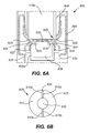
- FIG. 3 is a simplified cross-sectional view of the case shown in FIG. 1 ;
- FIG. 4A is a partial cross-sectional view of an earbud connector according to an embodiment of the disclosure.
- FIG. 4B is a plan view of the earbud connector illustrated in FIG. 4A ;
- FIG. 5A is a partial cross-sectional view of another embodiment of an earbud connector according to the disclosure.
- FIG. 5B is a plan view of the earbud connector illustrated in FIG. 5A ;
- FIG. 6A is a partial cross-sectional view of another embodiment of an earbud connector according to the disclosure.
- FIG. 6B is a plan view of the earbud connector illustrated in FIG. 6A ;
- FIG. 6C is an isometric exploded view of a connector assembly for the earbud connector illustrated in FIG. 6A ;
- FIG. 6D is an isometric view of the assembled earbud connector illustrated in FIG. 6A ;
- FIG. 7A is an isometric exploded view of another embodiment of an earbud connector according to the disclosure.
- FIG. 7B is an isometric view of the assembled earbud connector illustrated in FIG. 7A ;
- FIG. 8A is a partial cross-sectional view of another embodiment of an earbud connector according to the disclosure.
- FIG. 8B is a plan view of the connector on the earbud illustrated in FIG. 8A ;
- FIG. 8C is an isometric exploded view of the earbud connector illustrated in FIG. 8A ;
- FIGS. 9A and 9B are front and rear isometric views of one of the earbuds shown in FIG. 1 , respectively;
- FIG. 10 is a top view of the case shown in FIG. 1 with the case lid removed;
- FIG. 11 is a partial cross-sectional view of an earbud retained in a cavity within the case illustrated in FIG. 10 along section A-A;
- FIG. 12 is a partial cross-sectional view of an earbud retained in a cavity within the case illustrated in FIG. 10 along section B-B;
- FIG. 13 is an isometric view of a case having an over center lid according to some embodiments of the disclosure.
- FIG. 14 is an isometric view of the case shown in FIG. 13 with the over center lid in an open position;
- FIG. 15 is a graph showing attraction and repulsion forces associated with an over center lid according to some embodiments of the disclosure.
- FIG. 16 is a side view of a case that includes one pair of magnets with misaligned poles and one pair with a high permeable material surrounding them according to some embodiments of the disclosure;
- FIG. 17 is a side view of a case that includes two pairs of magnets attached to springs according to some embodiments of the disclosure.
- FIG. 18 is an isometric view of a magnet that may be used in a case according to some embodiments of the disclosure.
- FIG. 19 is an isometric view of a magnet that may be used in a case according to some embodiments of the disclosure.
- FIG. 20 is an isometric view of a magnet that may be used in a case according to some embodiments of the disclosure.
- FIG. 21 is an isometric view of a magnet that may be used in a case according to some embodiments of the disclosure.
- FIG. 22A is a side view of a case with a torsion spring over center mechanism according to some embodiments of the disclosure with its lid closed;
- FIG. 22B is an isometric view of the torsion spring over center mechanism illustrated in FIG. 22A ;
- FIG. 22C is a side view of the case illustrated in FIG. 22A with its lid partially open;
- FIG. 22D is a side view of the case illustrated in FIG. 22A with its lid open further;
- FIG. 23 is a simplified perspective view of a wireless charging system according to embodiments of the disclosure.
- FIG. 24 is a block diagram of an inductive power receiving system that can be part of the charging system illustrated in FIG. 23 according to some embodiments;
- FIG. 25 is a simplified plan view of the earbud case illustrated in FIG. 23 ;
- FIG. 26 is a block diagram of an embodiment of the inductive power transmitting system illustrated in FIG. 23 ;
- FIG. 27 is a simplified isometric view of an inductively charged case on an inductive charging system according to some embodiments of the disclosure.
- FIG. 28 is an isometric view of an electrical connector that can be included in the case illustrated in FIG. 1 according to some embodiments of the disclosure;
- FIG. 29 is an isometric exploded view of the electrical connector illustrated in FIG. 28 ;
- FIG. 30 illustrates isometric front and rear views of a left earbud according to some embodiments of the disclosure
- FIG. 31 illustrates isometric front and rear views of a right earbud according to some embodiments of the disclosure
- FIG. 32 is a cross-sectional view of one of the earbuds illustrated in FIGS. 30 and 31 ;
- FIG. 33 is a cross-sectional view of one of the earbuds illustrated in FIGS. 30 and 31 with some components removed;
- FIG. 34 is a plan view of a flexible circuit board that can be used in earbuds according to some embodiments of the disclosure.
- FIG. 35 is an isometric view of the flexible circuit board illustrated in FIG. 34 ;
- FIG. 36 is an isometric view of a connector structure that can be included in the earbuds illustrated in FIGS. 30 and 31 ;
- FIG. 37 is an isometric view of contacts for the connector structure illustrated in FIG. 36 according to some embodiments of the disclosure.
- FIG. 38 is an isometric view of the contact structure illustrated in FIG. 36 ;
- FIG. 39 is an isometric view of an earbud connector contact according to an embodiment of the disclosure.
- FIG. 40 is an isometric view of an insert molded connector contact that was illustrated in FIG. 39 ;
- FIG. 41 is an isometric view of an earbud with a capacitive sensor insert according to some embodiments of the disclosure.
- FIG. 42 is a cross-section of the earbud and the capacitive sensor insert illustrated in FIG. 41 ;
- FIG. 43 is a plan view of a capacitive sensor insert illustrated according to an embodiment of the disclosure.
- FIG. 44 is a plan view of a capacitive sensor insert illustrated according to an embodiment of the disclosure.
- FIG. 45A is an illustration of an earbud with an acoustic insert according to an embodiment of the disclosure.
- FIG. 45B is an illustration of the earbud with the acoustic insert illustrated in FIG. 45A ;
- FIG. 46 is a flowchart illustrating steps associated with manufacturing an earbud according to some embodiments of the disclosure.
- FIG. 47 illustrates a system 47 according to some embodiments of the disclosure
- FIG. 48 is a simplified block diagram of a system 4800 according to some embodiments of the disclosure.
- FIG. 49 is a flowchart illustrating steps associated with pairing wireless headphones with a host device according to some embodiments of the disclosure.
- FIG. 50 is a flowchart illustrating steps associated with activating a wireless radio in earbuds according to some embodiments of the disclosure.
- FIG. 51 is a flowchart illustrating steps associated with deactivating a wireless radio in earbuds according to some embodiments of the disclosure.
- Some embodiments of the present disclosure relate to portable listening devices and cases for containing and/or charging such devices that have improved features that can improve the user experience associated with using the case and/or the portable listening device. While the present disclosure can be useful for a wide variety of portable listening devices, some embodiments of the disclosure are particularly useful for wireless earbuds and cases for wireless earbuds as described in more detail below.
- a pair of wireless earbuds are sized and shaped to fit within a case that can also include a rechargeable battery and charging circuitry.
- the pair of earbuds can be charged when an earbud detector within the case detects that the earbuds are placed within the case.
- the case can include sensors to detect if the lid is open such that the wireless radio within each earbud can be activated so they are ready for use by the user. Similarly, when the lid is closed the wireless radio can be shut off so the charge in the earbud batteries is conserved.
- the case can have a pairing button on it that is operable to place the earbuds in a pairing mode.
- the case can also have one or more charge indicator lights to inform the user of the charge level in the case battery as well as the charge level in each earbud.
- the case can have a lid with an over center configuration such that the lid is in a first stable position when in a closed position and is in a second stable position when in the open position, but is in an unstable position in-between the closed position and the open position.
- the over center configuration can be achieved by using two pairs of magnets while in other embodiments it can be achieved with a torsion spring.
- the case can have one or more magnets within it to attract the earbuds into cavities formed within the case and to retain them until a user removes them.
- the case can be liquid-tight to prevent liquid from damaging the internal circuitry.
- the electrical connections for both the earbud recharging and for recharging the case can be resistant to penetration by a liquid.
- the earbuds can have an acoustic insert that forms one or more acoustic ports such as a bass port vent and a rear vent that enable the internal speaker to provide audio performance in the confined space within the earbud housing.
- the earbud case can be used to initiate Bluetooth® pairing of the earbuds with a host device.
- a lid position sensor detects when the lid is open and initiates pairing of the earbuds.
- the term “portable listening device” includes any portable device designed to play sound that can be heard by a user. Headphones are one type of portable listening device, portable speakers are another.
- the term “headphones” represents a pair of small, portable listening devices that are designed to be worn on or around a user's head. They convert an electrical signal to a corresponding sound that can be heard by the user. Headphones include traditional headphones that are worn over a user's head and include left and right listening devices connected to each other by a headband, headsets (a combination of a headphone and a microphone), and earbuds (very small headphones that are designed to be fitted directly in a user's ear).
- earbuds which can also be referred to as earphones or ear-fitting headphones, includes both small headphones that fit within a user's outer ear facing the ear canal without being inserted into the ear canal, and in-ear headphones, sometimes referred to as canalphones, that are inserted in the ear canal itself.
- FIG. 1 depicts a simplified plan view of a case 100 for a pair of wireless earbuds according to some embodiments of the disclosure.
- case 100 includes a housing 105 , also called a body, having one or more cavities 110 a , 110 b configured to receive a pair of earbuds 115 a , 115 b .
- cavities 110 a , 110 b can be positioned adjacent to each other on opposite sides of a center plane of case 100 .
- Each cavity 110 a , 110 b can be sized and shaped to match that of its respective earbud 115 a , 115 b .
- Each cavity can include a stem section 116 a , 116 b and a bud section 117 a , 117 b .
- Each stem section 116 a , 116 b can be an elongated generally cylindrical cavity that extends from its respective bud section 117 a , 117 b towards a bottom 106 of case 100 .
- Each bud section 117 a , 117 b can be offset from its respective stem section 116 a , 116 b and open at an upper surface 108 of housing 105 .
- Embodiments of the disclosure are not limited to any particular shape, configuration or number of cavities 110 a , 110 b and in other embodiments cavities 110 a , 110 b can have different shapes to accommodate different types of earbuds, different configurations and/or can be a single cavity or more than two cavities.
- Case 100 further includes a lid 120 attached to housing 105 .
- Lid 120 is operable between a closed position where lid 120 is aligned over one or more cavities 110 a , 110 b fully enclosing pair of earbuds 115 a , 115 b within the housing, and an open position where the lid is displaced from the housing and cavities 110 a , 110 b such that a user can remove the earbuds from the cavities or replace the earbuds within the cavities.
- Lid 120 can be pivotably attached to housing 105 and can include a magnetic or mechanical system (not shown in FIG. 1 ) that provides lid 120 with a bi-stable operation, as described more fully below.
- case 100 can also include a charging system 125 configured to charge pair of earbuds 115 a , 115 b ; one or more magnets 130 configured to orient and retain the pair of earbuds within one or more cavities 110 a , 110 b ; and other features that are further described below.
- a charging system 125 configured to charge pair of earbuds 115 a , 115 b
- one or more magnets 130 configured to orient and retain the pair of earbuds within one or more cavities 110 a , 110 b ; and other features that are further described below.
- FIG. 2 is a simplified block diagram of system 200 according to an embodiment of the present disclosure.
- System 200 can include pair of earbuds 202 a , 202 b , a case 204 for the pair of earbuds, and a power source 205 for charging the case.
- Earbuds 202 a , 202 b can be positioned within case 204 (e.g., within an interior space or cavity of the case defined by a housing or an insert within the housing) where they can be conveniently stored and charged.
- Case 204 can be representative of case 100 and earbuds 202 a , 202 b can be representative of earbuds 115 a , 115 b discussed above with respect to FIG. 1 .
- Each earbud 202 a , 202 b can each have one or more inputs 255 , internal components 260 and one or more outputs 265 .
- one or more inputs 255 can be a microphone input and one or more buttons or sensors that register a user's touch.
- an accelerometer or a capacitive sensor can be used as an input 255 and can be activated, for example, by a user to answer a call or command earbuds 202 a , 202 b to enter a pairing mode that can be indicated by a light on either or both earbuds.
- one or more internal components 260 can include a speaker, a microphone, a rechargeable battery, a processor, and/or other circuitry and components.
- one or more outputs 265 can be audio from a speaker, a light or other indicator. In some embodiments the indicator light can indicate an incoming call, a battery charge level, a pairing mode or other function.
- each of earbuds 202 a , 202 b can include a wireless radio that can be both an input 255 and an output 265 device.
- the wireless radio can enable the earbuds to receive an audio signal from an audio player, such as a smart phone.
- one or more of earbuds 202 a , 202 b include a radio that can also transmit an audio signal such as a microphone signal from one or more of the earbuds.
- one or more of earbuds 202 a , 202 b can include a radio that can transmit communication signals that can command the receiving device (e.g., a host device such as a smartphone) to perform one or more functions such as, but not limited to, connect a phone call, disconnect a phone call, pause audio playback, fast forward or rewind audio playback or mute a microphone signal.
- the wireless radio can employ any short range, low power communication protocol such as Bluetooth®, low power Bluetooth®, or Zigbee among protocols.
- Case 204 can include a case processor 210 , an earbud detector 215 , radio 217 , a lid sensor 220 , case charging circuitry 225 , a battery 227 and earbud charging circuitry 230 .
- Case 204 can also include an earbud interface 245 that enables circuitry within case 204 to communicate with and/or charge earbuds 202 a , 202 b and power source interface 250 that couples the case to wired or wireless power source 205 , such as an AC or DC power source or an inductive charging pad.
- case charging circuitry 225 , battery 227 , earbud charging circuitry 230 and interfaces 245 and 250 are all representative components of charging system 125 shown in FIG. 1 .
- Power source interface 250 can be part of a receptacle connector for a micro USB connector, a Lightening connector or other connector that can provide power to earbud case 204 .
- power interface 250 can include a wireless power receiver, such as one or more wireless power receiving coils, that can receive inductive power from power source 205 .
- Earbud interface 245 can transfer power and/or data between case 204 and the earbuds via case transfer interface 270 in each earbud.
- Earbud interface 245 can include an electrical connector, such as one of the connectors described herein with respect to FIGS. 4A-8C , a different type of electrical connector, or a wireless power transmitter, such as a wireless power transmitting coil that can transmit inductive power to an inductive power receiver within the earbuds.
- Case processor 210 can be configured to control various functions of case 204 as described in more detail below.
- earbud detector 215 includes one or more sensors that detect when one or both of earbuds 202 a , 202 b are placed within case 204 .
- earbud detector 215 can be a circuit that periodically “pings” the earbud contacts within case 204 to determine if either earbud 202 a , 202 b is present.
- earbud detector 215 can be any type of mechanical or electrical sensor, such as, but not limited to, a magnetic sensor, an optical sensor, a switch, a hall effect sensor, a flux sensor, a capacitive sensor, a photodetector, a proximity detector, a momentary switch or any other type of sensor.
- earbud detector 215 is a flux sensor
- the flux sensor can be beneficial to minimizing power consumption of case 204 .
- a flux sensor can be formed in case 204 for each earbud from a coil of wire and one or more magnets within earbuds 202 a , 202 b .
- Each flux sensor can be configured to generate a current in the coil of wire when an earbud is inserted or withdrawn from case 204 and the magnet within the earbud passes through the coil of wire.
- a flux sensor can function as a completely passive sensor that requires no power to operate, and generates its own energy to notify processor 210 of the removal or replacement of either earbud 202 a , 202 b within case 204 .
- a hall effect sensor can also be beneficial to minimize power consumption.
- one or more sensors can be beneficial so that a voltage bias (e.g., a ping) need not be applied to the earbud connectors, thus mitigating contact corrosion and/or oxidation in moist environments.
- a voltage bias e.g., a ping
- case 204 can include separate earbud receiving cavities within the case, such as cavities 110 a , 110 b described above, and earbud detector 215 can include first and second earbud detectors—one detector for each cavity.
- the first earbud detector can be operatively coupled to detect when an earbud (e.g., a left earbud) is inserted within a first of the cavities and the second earbud detector can be operatively coupled to detect when an earbud (e.g., a right earbud) is inserted within the other cavity.
- a single detector can detect when either earbud 202 a , 202 b is placed within case 204 .
- earbud detector 215 can generate a detect signal that can be sent to and processed by other circuitry within case 204 to initiate charging of the buds.
- earbud detector 215 includes first and second detectors that can detect the insertion of the left and right earbuds (or first and second earbuds that are interchangeable between the left and right ears), respectively, each earbud detector can generate a separate detect signal that can initiate charging of the detected earbud only.
- earbud detector 215 can also be used to stop charging. For example, earbud detector 215 can detect when either or both of the earbuds are removed from the case and generate a removal signal that stops the charging of the removed earbud or earbuds.
- earbud detector 215 can initiate the charging process of each earbud 202 a , 202 b when the earbud detector detects that electrical contact is made between the earbuds and corresponding charging contacts within the housing (e.g., within each cavity 110 a , 110 b ). More specifically, in various embodiments earbud detector 215 can periodically “ping” the charging contacts to see if either or both earbuds 202 a , 202 b are present within each cavity 110 a , 110 b .
- earbud detector 215 is part of processor 210 and the processor does the sensing. In other embodiments, earbud detector 215 is separate active/passive components. In various embodiments, case 204 does not include a case processor 210 and instead, circuitry comprising various active and/or passive components is configured to perform the functions described herein and attributed to the processor.
- case processor 210 can communicate with pair of earbuds 202 a , 202 b by sending and receiving data through earbud interface 245 (and through case interface of either or both earbuds) and can communicate with power source 205 by sending and receiving data through power source interface 250 .
- earbud interface 245 and power source interface 250 can be capable of carrying both power and data signals for single or bidirectional communication.
- separate power and data contacts can be used while in various embodiments one set of contacts is used for both power and data.
- power source 205 can be a computing device that communicates with power source interface 250 through an interface (not shown), such as a USB interconnect or a Lightning interconnect developed by Apple Inc.
- the interconnect can provide DC current to case battery 227 for charging and can provide bidirectional communication between case processor 210 and the computing device.
- power source 205 can transmit firmware updates to both case processor 210 and pair of earbuds 202 a , 202 b through the same contacts that are used to charge the devices.
- Data communication between earbud interface 245 and pair of earbuds 202 a , 202 b can use a similar communication protocol as discussed above or any other protocol such as, for example, serial communications.
- case 204 can include a wireless radio 217 that enables the case to transmit and receive data communications with earbuds 202 a , 202 b and a host device (e.g., a smartphone, a tablet computer, a laptop computer or the like) in addition to, or instead of, relying on data exchange through interfaces 245 and 250 .
- a wireless radio 217 can be used to initiate a pairing sequence between earbuds 202 a , 202 b and a host device.
- radio 217 can be used to receive a music download from a host device to be stored in case 204 .
- Lid sensor 220 can detect when a lid to the case (e.g., lid 120 shown in FIG. 1 ) is in the open position and when the lid is in the closed position.
- case processor 210 is coupled to lid sensor 220 and receives signals from the lid sensor indicating when the lid is opened and closed. More specifically, in some embodiments lid sensor 220 can generate and send an “open” signal to processor 210 upon detecting when the lid is opened, and lid sensor 220 can generate and send a “closed” signal to processor 210 upon detecting the closure of the lid.
- Processor 210 can be configured to communicate with pair of earbuds 202 a , 202 b to turn ON their wireless radios when the lid is in the open position (e.g., in response to receiving the “open” signal) so they are ready for use by a user and turn OFF their wireless radios when the lid is in the closed position (e.g., in response to receiving the “closed” signal) to conserve their power.
- lid sensor 220 can also trigger case processor 210 to enter a pairing mode when the case lid is opened, as explained in more detail below.
- case processor 210 can communicate with pair of earbuds 202 a , 202 b through earbud interface 245 and case interface 270 using a wired connection as discussed above, while in other embodiments case processor 210 can communicate with earbuds 202 a , 202 b through interfaces 245 and 270 wirelessly in addition to, or instead of, using a wired connection.
- lid sensor 220 can be any type of mechanical or electrical switch including, but not limited to, a momentary switch, a capacitive sensor, a magnetic sensor (e.g., hall effect) or an optical sensor.
- Case battery 227 provides power for the circuitry associated with case 204 and can be a rechargeable battery that can be charged by power source 205 and enclosure charging circuitry 225 through power source interface 250 .
- Case battery 227 is also coupled to earbud interface 245 and can charge pair of earbuds 202 a , 202 b in conjunction with earbud charging circuitry 230 .
- earbud charging circuitry 230 can charge pair of earbuds 202 a , 202 b anytime they are properly stored within cavities 110 a , 110 b even though case 204 is not coupled to power source 205 .
- case 204 can be capable of charging pair of earbuds 202 a , 202 b while the case is, for example, in a user's pocket as long as case battery 227 has sufficient charge.
- case battery 227 can be sealed within case 204 , while in some embodiments the case battery can be removable for servicing and/or replacement with another charged battery.
- Case processor 210 can additionally be coupled to case charging circuitry 225 that can control the charging of case battery 227 (e.g., control the voltage and current supplied to the battery to optimize the speed of charging and the life of the battery).
- case charging circuitry 225 can include a DC/DC converter, an AC/DC converter, battery voltage level monitoring circuitry and/or safety features to properly charge case battery 227 .
- case processor 210 can be coupled to earbud charging circuitry 230 that can control the charging of batteries within pair of earbuds 202 a , 202 b (e.g., control the voltage and current supplied to the batteries to optimize the speed of charging and the life of the batteries) through earbud interface 245 .
- earbud charging circuitry 230 can include a DC/DC converter, battery voltage level monitoring circuitry and/or safety features to properly charge earbud batteries.
- case 204 can include one or more charge indicators 235 that can indicate a charge level of case battery 227 and/or the pair of earbud batteries such that a user can see the indicators on an outer surface of case 100 (see FIG. 1 ).
- charge indicators 235 can include three LEDs, one indicating the status for case battery 227 and one for indicating the status of the battery in each of pair of earbuds 202 a , 202 b .
- charge indicators 235 can be a first color (e.g., green) if the respective battery is near full charge, a second color (e.g., amber) if the respective battery is less than 75 percent charged and a third color (e.g., red) if there is no charge or limited charge.
- charge indicators 235 can include multiple LEDs for each of battery 227 , earbud 115 a and earbud 115 b , where the number of LEDs lit indicate the strength of the battery for each component. For example, in one particular instance three sets of three LEDs can be included on case 204 .
- case 204 can also include one or more user input devices 240 .
- Each included input device 240 can be a button or other type of input that, in response to being activated by or otherwise receiving input from a user, generates a signal that can be communicated to processor 210 or other circuitry within case 204 .
- Processor 210 or the other circuitry, can then act upon the signal.
- the wireless radios used by pair of earbuds 202 a , 202 b can be a Bluetooth® or other radio system that requires a pairing sequence to establish communication between the pair of earbuds and a wireless transmitter in an electronic device.
- processor 210 can send a signal to the earbuds via earbud interface 245 to place the wireless radios within pair of earbuds 202 a , 202 b into a pairing mode. More specifically, in some embodiments the user can depress a pairing button located on case 204 that notifies case processor 210 to instruct pair of earbuds 202 a , 202 b via interface 245 to enter a pairing mode. In some embodiments pair of earbuds 202 a , 202 b can be required to be within the case (e.g., within cavities 110 a , 110 b as shown in FIG. 1 ) while entering the pairing mode while in other embodiments the earbuds may not need to be within case 204 and only need to be within wireless communication range of the case. Further details with regard to wireless pairing will be discussed later in the application.
- case 100 includes housing 105 having cavities 110 a , 110 b for holding pair of earbuds 115 a , 115 b and various electronic circuitry.
- Case 100 further includes lid 120 attached to housing 105 and operable between a closed position where lid 120 is aligned over one or more cavities 110 a , 110 b fully enclosing pair of earbuds 115 a , 115 b within housing and an open position where the cavities 110 a , 110 b are exposed such that a user can remove or replace the earbuds within the cavities.
- lid 120 can be pivotably attached to housing 105 with joint 305 enabling the lid to be operable between a closed position and an open position.
- lid 120 can have a bi-stable position where it is stable in the closed and open positions, but unstable between those positions such that it tends to be attracted to either the closed or the open position.
- the bi-stable operation can be enabled by employing a first pair of magnetic elements 310 a , 310 b and a second pair of magnetic elements 315 a , 315 b , as discussed in more detail below.
- a lid sensor 220 can be disposed in housing 105 and configured to detect when lid 120 is in the closed position (e.g., when a detectable medium 320 is adjacent the lid sensor) and when the lid is in the open position (e.g., when the detectable medium is not adjacent the lid sensor).
- the detectable medium can be a magnetic material.
- Pair of earbuds 115 a , 115 b can fit within cavities 110 a , 110 b each of which is sized and shaped to accept one of the earbuds.
- Lid 120 can include a cavity (or pair of cavities 360 a , 360 b as shown in FIG. 3 ) into which the portion of each earbud that extends out of its respective cavity 110 a , 110 b , extents into. While not shown in FIG. 3 , each cavity 360 a , 360 b can be sized and shaped to match the size and shape of the portion of each earbud the cavity surrounds to more securely store the earbuds within case 100 .
- Each earbud can include a speaker assembly (not shown in FIG. 3 ) disposed within a housing of the earbud.
- the speaker assembly can include a driver unit aligned to emit sound from the directional sound port.
- the driver unit can include an electromagnetic voice coil, a speaker diaphragm and a driver magnet (shown in FIG. 3 as magnet 325 ) operatively coupled to the voice coil to move the diaphragm in response to electrical signals and produce sound.
- earbuds can include an additional magnetic plate 330 that is not operatively coupled to the voice coil. Either or both of magnet 325 and magnetic plate 330 can be attracted to at least one housing magnetic component 130 disposed within case 100 .
- magnetic plate 330 can be made from a magnetic material and in various embodiments it can be made with a metal injection molding process. In some embodiments magnetic plate 330 is magnetized while in other embodiments it is not magnetized but is magnetically attractable.
- the magnetic plate 330 in each earbud can be positioned direction adjacent to the earbud housing. Additionally, the magnetic plate be contoured to match the curvature of the housing thereby ensuring a minimum distance between the magnetic plate and the housing across the surface are of the magnetic plate. Similarly, at least some or the housing magnetic components 130 can be disposed as close as possible to the surface of the receiving cavity at a location that is spaced directly apart from where the magnetic plate 330 will be when an earbud is received within the cavity. In some embodiments the housing components 130 can be contoured to match the curvature of the receiving area (which matches the curvature of its respective earbud) to minimize the distance between the housing magnetic component 130 and the magnetic plate 330 .
- housing 105 and lid 120 can be made from the same material while in various embodiments they can be made from different materials. In some embodiments both housing 105 and/or lid 120 can be made from a plastic material, stainless steel, aluminum or any other material.
- Charging system 125 can include a circuit board 335 or other electrical routing structure, a rechargeable case battery 227 , electrical interconnects 340 to pair of earbuds 115 a , 115 b , one or more electronic components, such as case processor 210 , and an electrical connector 345 for connecting to power source 205 (see FIG. 2 ).
- connector 345 can, for example, be a non-proprietary interface such as a USB connector or can be a proprietary interface such as the Lightning connector developed by Apple Inc.
- connector 345 can be liquid-tight, as discussed in more detail below.
- One or more charge indicators 235 can be visible on an exterior surface 350 of case 100 .
- each earbud in pair of earbuds 115 a , 115 b can be electrically coupled to charging system 125 by a connector 347 disposed at an end of a stem portion of each earbuds 115 a , 115 b , as discussed in more detail below.
- FIGS. 4A-8C illustrate several examples of electrical connectors that can be used between each individual earbud in pair of earbuds 115 a , 115 b and case 100 (see FIG. 3 ), similar to connector 347 in FIG. 3 . While each of FIGS. 4A-8C illustrate an earbud connector for a first earbud 115 a , it is to be understood that second earbud 115 b can be configured identical to first earbud 115 a and thus include a similar electrical connector. Additionally, while the embodiments illustrated in FIGS. 4A-8C include external contacts that are disposed at the end of a stem of the earbud, the contacts can be at different locations in other embodiments.
- FIGS. 4A and 4B are simplified cross-sectional views of an electrical connector 400 that can be incorporated into earbud case 100 and an electrical connector 405 at the end of a stem portion of an earbud 115 a according to an embodiment of the disclosure.
- Electrical connector 405 can be used to conduct power and/or data according to some embodiments of the disclosure.
- Connector 405 can be part of an earbud interface and can include first and second earbud contacts 410 , 415 , respectively.
- a bottom view of electrical connector 405 is illustrated in FIG. 4B .
- earbud contacts 410 , 415 can be annular and separated by an insulator 420 .
- Receptacle connector 400 can be used in a case such as case 100 illustrated above and can have a first earbud case contact 425 and a second earbud case contact 430 .
- First annular contact 410 can interface with first earbud contact 425 and second annular contact 415 can interface with second earbud contact 430 .
- First and second annular contacts 410 , 415 can be any type of conductive material including gold, silver or palladium plated copper.
- first and second earbud contacts 410 , 415 are power and ground contacts. That is, either of first and second earbud contacts 410 , 415 , respectively can be used for power while the other can be used for ground. As examples, in some embodiments first contact 410 is used for power and second contact 415 is ground while in other embodiments first contact 410 is used for ground and second contact 415 is used for power. In various embodiments other connector configurations can be used that have more than two contacts.
- First and second earbud case contacts 425 , 430 can be coupled to charging system 125 (see FIG. 3 ) with electrical interconnects 340 in case 100 to facilitate charging and communication of each earbud 115 a , 115 b .
- a circular microphone aperture 435 can be located in the center of second annular contact 415 of each earbud 115 a , 115 b to facilitate two way telephonic communication and/or noise cancellation.
- Microphone aperture 435 can be covered by an aesthetic acoustic mesh to protect the microphone from debris and damage.
- FIGS. 5A and 5B illustrate another example receptacle connector 500 that can be incorporated into earbud case 100 and an electrical connector 505 at the end of a stem portion of an earbud 115 a according to an embodiment of the disclosure.
- Connector 500 has one annular contact and one center contact, however, as described in more detail below.
- Connector 505 can be part of an earbud interface and can include first and second earbud contacts 510 , 515 , respectively.
- a bottom view of electrical connector 505 is illustrated in FIG. 5B .
- ring contact 510 can be ring shaped and circular contact 515 can be circular with the contacts separated by an insulator 520 (e.g., insulator 520 can be an air gap).
- Ring contact 510 can interface with first earbud contact 525 and circular contact 515 can interface with second earbud contact 530 .
- a circular microphone aperture 535 can be located between ring contact 510 and circular contact 515 so one or more of pair of earbuds 115 a , 115 b can be used for two way telephonic communication.
- FIGS. 6A and 6B illustrate another example receptacle connector 600 that can be incorporated into earbud case 100 and an electrical earbud connector 605 disposed at the end of a stem portion of an earbud 115 a according to an embodiment of the disclosure.
- Receptacle connector 600 can make electrical contact with electrical earbud connector 605 as described in more detail below.
- Earbud connector 605 can be part of an earbud interface and can include first and second earbud contacts 610 , 615 , respectively.
- a bottom view of electrical earbud connector 605 is illustrated in FIG. 6B . As shown in FIG. 6B , contacts 610 , 615 can be spaced from each other in an oppositional and symmetrical relationship.
- each of earbud contacts 610 and 615 can have a partial annular shape (i.e., a partial ring) with the open portions of each contact facing the other.
- contact 610 can include ends 610 a , 610 b and contact 615 can include ends 615 a , 615 b where end 610 a is spaced apart from end 615 a and end 610 b is spaced apart from end 615 b .
- FIG. 6B illustrates each of contacts 610 , 615 as half rings, in other embodiments the contacts can include shorter length arcs and/or have different opposing shapes altogether.
- Earbud contacts 610 , 615 can be separated from each other by an insulator 620 (e.g., insulator 620 can be a dielectric material as discussed in more detail below).
- Earbud contact 610 can interface with first earbud case contact 625 and earbud contact 615 can interface with second earbud case contact 630 .
- a circular microphone aperture 635 can be located between earbud contacts 610 and 615 enabling pair of earbuds 115 a , 115 b to be used for two way telephonic communication.
- Receptacle connector 600 can include a contact carrier 640 that retains earbud case contacts 625 , 630 as described in more detail below. In some embodiments, contact carrier 640 can make earbud receptacle cavity 645 liquid-tight.
- each of the first and second earbud contacts 610 , 615 can include a contact portion that extends into an earbud receiving cavity of the earbud case when the earbud is positioned within the cavity.
- Receptacle connector 600 can include a pair of earbud case contacts 625 , 630 that are positioned on opposite sides of and extend into the earbud receiving cavity. Earbud case contacts 625 , 630 can be held within receiving slots 628 , 633 of a contact carrier 640 as discussed further below.
- each earbud contact 610 , 615 can have an arcuate cross-section that makes contact with arcuate contact portions 626 , 631 of contacts 625 , 630 respectively, during a mating event when the earbud is inserted into the earbud receiving cavity.
- the combination of arcuate surfaces on the earbud contact and earbud case contact enable a contact wiping motion each time the earbuds are inserted within and drawn out of the receptacle connector, creating a reliable interconnect.
- contacts 625 , 630 are illustrated in a deflected state that illustrates their approximate position when earbud 115 a is fully inserted into its receiving cavity such that the earbud contact is engaged with the earbud case connector.
- the same contacts 625 , 630 are also illustrated in FIG. 6A in a non-deflected state 627 , 632 showing the contacts extending into the earbud receiving cavity prior to being mated with the earbud contacts of earbud 115 a .
- the earbud case contacts 625 , 630 come in contact with the earbud contacts and deflect outward.
- the exterior contacting surfaces of the earbud contacts and earbud case contacts rub against each other during both the mating event and during a de-mating event when the earbud 115 a is withdrawn from the earbud receiving cavity.
- the deflecting arcuate portions 626 , 631 of contacts 625 , 630 respectively are deflected by arcuate portions of first and second earbud contacts 610 , 615 , respectively during insertion and withdrawal of the first and second earbuds. Since the arcuate portions are in direct contact and contacts 625 , 630 are in a deflected (e.g., spring loaded state), pair of earbuds 115 a , 115 b has a vertical (e.g., ejecting) force applied to them when fully mated with the case.
- one or more magnets can be used to overcome the vertical force and hold the earbuds within their respective cavities.
- one of contacts 625 , 630 can be arranged to make contact with the earbud contacts 610 , 615 , first by preloading one of contacts 625 , 630 at a different height than the other (e.g., sequential contacts). This can be useful in some embodiments to make a ground connection to the earbud first before making an active electrical connection with it.
- the wiping contacts and the sequentially contacting contacts can be used in any of the connector embodiments disclosed herein.
- contact carrier 640 can include a debris recess 609 disposed below the contact interface region.
- Debris recess 609 can have a cup-like shape defined by sidewalls 609 a and can be useful for providing a location for debris that falls into either earbud cavity.
- Debris recess 609 can be disposed between earbud case contact receiving slots 628 , 633 and spaced apart from the contact area so the debris does not interfere with the earbuds making electrical contact with receptacle connector 600 .
- Debris recess 609 can further be open to the earbud receiving cavity so that debris can be periodically cleaned out as needed.
- a separate debris recess 609 is disposed under each earbud contact area while in other embodiments a single debris recess can be sufficiently wide to capture debris from both contact areas.
- Debris recess 609 can be included in any of the connector embodiments disclosed herein.
- debris recess 609 has a depth below arcuate portions 626 , 631 of contacts 625 , 630 that is 50 percent or more than a diameter of debris recess 609 .
- debris recess 609 has a depth that is 75 percent or more than the diameter of debris recess 609 while in another embodiment its depth is 100 percent (e.g., having a depth to diameter ratio of 1:1) or more of the diameter.
- contacts 625 can be made out of a copper, nickel and silver alloy while in other embodiments they can be made out of a phosphor and bronze alloy, and in other embodiments a different alloy can be used.
- connector 600 includes first and second shells 650 , 655 that define receiving cavities for a pair of earbuds retaining and guiding a stem portion of each earbud into case 100 (see FIG. 1 ). While not shown in FIG. 6C , the receiving cavity in each shell can include an elongated tube portion that opens to a larger earbud receiving opening.
- the elongated tube portion can be sized and shaped to accommodate the stem section of an earbud and the larger earbud receiving opening can be sized and shaped to partially or fully accommodate the ear interface portion (i.e., the portion of the earbud that fits within a user's ear).
- shells 650 , 655 can be separate components joined together by the contact carrier while in other embodiments shells 650 , 655 can be a single component that can be formed, for example, in a molding process, a 3 D printing process or with a milling process.
- Contact carrier 640 holds first and second earbud contacts 625 , 630 , respectively, that can interface with a first earbud, and also holds third and fourth earbud contacts 660 , 665 , respectively, that can interface with a second earbud.
- a collar 670 can be bonded to a top surface 675 of contact carrier 640 .
- collar 670 can have a removable tie bar (not shown in FIG. 6C ) that holds the three pieces of the collar together during assembly and that can then be removed after assembly such that the tie bar is not included within a finished earbud case.
- Distal ends 680 , 685 of first and second shells 650 , 655 can be narrower than the elongated tube portion of shell 650 , 655 , and each distal end 680 , 685 can be fit within and bonded to collar 670 forming a completed shell and receptacle connector assembly 690 , illustrated in FIG. 6D .
- each earbud case contact 625 , 630 fits within a respective contact opening of shell 650 and each earbud case contact 625 , 630 fits within a respective contact opening (e.g., opening 687 visible in FIG. 6C ) of shell 655 .
- Each contact opening (e.g., opening 687 ) enables its respective contact to extend into the earbud receiving cavity within its respective shell 650 , 655 to make electrical contact with an earbud contact during a mating event.
- shell and contact assembly 690 can create a liquid-tight seal as defined herein.
- Shell and contact assembly 690 can subsequently be assembled into a case, such as case 100 illustrated in FIG. 1 .
- first and second shells 650 , 655 can be a single shell having two cavities, one cavity for each earbud.
- a liquid-tight seal shall mean a seal that conforms to one or more of the following ratings as defined by the International Protection Rating and International Electrochemical Commission (IEC) 60529 that can also be known as the I.P.68 rating.
- IEC International Protection Rating and International Electrochemical Commission
- the liquid-tight seal will protect the connector assembly against the harmful ingress of water and have a “liquid ingress” rating between 1 (dripping water) and 8 (immersion beyond 1 meter).
- the liquid-tight seal shall be rated between 1 (dripping water) and 4 (splashing water) while in some embodiments the liquid-tight seal shall be rated between 2 (dripping water with device tilted at 15 degrees) and 5 (water jet).
- liquid-tight seal shall be rated between 3 (spraying water) and 6 (powerful water jets) while in some embodiments the liquid-tight seal shall be rated between 4 (splashing water) and 7 (immersion up to 1 meter). In various embodiments the liquid-tight seal shall be rated between 5 (water jets) and 8 (immersion beyond 1 meter) while in some embodiments liquid-tight shall mean the seal will protect the electronic device against liquid ingress up to 100 feet for 30 minutes.
- FIGS. 7A and 7B another example of a receptacle connector 700 is illustrated that is similar to connector 600 illustrated in FIGS. 6A and 6B .
- Receptacle connector 700 has a different configuration for the contacts and the contact carrier, however, as described in more detail below.
- This embodiment can use the same earbud connector shown in FIGS. 6A and 6B , where the earbud contacts are semicircular and separated by an insulator.
- a contact carrier 740 holds first and second earbud contacts 725 , 730 , respectively, that can interface with a first earbud, and also holds third and fourth earbud contacts 760 , 765 , respectively, that can interface with a second earbud.
- a cap 770 can be bonded to a bottom surface 775 of contact carrier 740 with a layer of adhesive 773 .
- distal ends of first and second shells 750 , 755 can be fit within and bonded to contact carrier 740 forming a completed shell and receptacle connector assembly 790 .
- Shell and contact assembly 790 can be liquid-tight, meeting one or more of the ranges as defined herein. Shell and contact assembly 790 can subsequently be assembled into a case, such as case 100 illustrated in FIG. 1 .
- first and second earbud contacts can have an arcuate cross-section and can make contact with arcuate portions of receptacle connector contacts 725 , 730 .
- the combination of arcuate surfaces can enable a wiping motion each time the earbuds are inserted within and drawn out of the receptacle connector, creating a reliable interconnect.
- one contact can be arranged to make contact with the earbud first.
- the contacts can be preloaded at different heights. This can be useful in some embodiments to ground the earbud first before making an active electrical connection with it.
- FIGS. 8A and 8B another example of a receptacle connector 800 is illustrated that is similar to connector 400 illustrated in FIGS. 4A and 4B .
- Receptacle connector 800 has a different configuration for the inner and outer contacts, however, as described in more detail below.
- earbud contacts 810 , 815 can be annular and separated by an electrical insulator 820 .
- First annular contact 810 can interface with first earbud contact 825 and second annular contact 815 can interface with second earbud contact 830 .
- First and second annular contacts 810 , 815 can be formed from any type of conductive material including copper and copper alloys and can be plated with any metal.
- a circular microphone aperture 835 can be located in the center of second annular contact 815 so one or more of pair of earbuds 115 a , 115 b (see FIG. 1 ) can be used for two way telephonic communication.
- Microphone aperture 835 can be covered by an aesthetic acoustic mesh to protect the microphone from debris and damage.
- first and second earbud contacts can have an arcuate cross-section and can make contact with arcuate portions of contacts 825 , 830 respectively in receptacle connector 800 .
- the combination of arcuate surfaces can enable a wiping motion each time the earbuds are inserted within and drawn out of the receptacle connector, creating a reliable interconnect.
- an exterior surface 821 of the earbud stem can be flush with an exterior side surface of the earbud contacts.
- one contact can be arranged to make contact with the earbud first.
- the contacts can be preloaded at different heights. This can be useful in some embodiments to ground the earbud first before making an active electrical connection with it.
- FIG. 8C an exploded view of receptacle connector 800 is shown illustrating how it can be coupled to first and second shells 850 , 855 that retain and guide a stem portion of each earbud into case 100 (see FIG. 1 ).
- Contact carrier 840 holds first and second earbud contacts 825 , 830 , respectively, that can be used with a first earbud, and also holds third and fourth earbud contacts that can be used with a second earbud.
- Contact carrier 840 can be bonded to distal ends 880 , 885 of first and second shells 850 , 855 , respectively, forming a completed shell and receptacle connector assembly.
- Shell and contact assembly can create a liquid-tight seal as defined herein.
- Shell and contact assembly 690 can subsequently be assembled into a case, such as case 100 illustrated in FIG. 1 .
- first and second shells 850 , 855 can be a single shell having two cavities, one cavity for each earbud.
- the electrical connector (for example connector 405 in FIG. 4A ) on pair of earbuds 115 a , 115 b may not be an annular (e.g., ring shaped) external contact-type connector and can be any other type of electrical connector, such as, but not limited to a pin and socket, a pin and contact pad or a wiping arm and contact pad.
- one or more contact pads can be located on a vertical portion of the stem portion of the pair of earbuds and a wiping arm can interface with them.
- an interface connector can be disposed on the ear portion of the earbud housing.
- a mating connector can be disposed within the case and can interface with the connector when the earbud is placed in its respective cavity.
- such a connector can be gold plated to minimize corrosion that can occur as a result of being in contact with a user's ear for extended periods of time.
- wireless inductive charging of the earbuds can be used.
- FIGS. 9A and 9B illustrate front and rear perspective views, respectively, of one of wireless earbuds 115 a , 115 b .
- earbuds 115 a , 115 b include an external housing having an ear interface portion 903 and a stem portion 910 .
- Ear interface portion 903 can be formed to fit at least partially within a user's ear and can be non-occluding, as discussed in more detail herein.
- An aesthetic acoustic mesh 915 can fit on ear interface portion 903 and allow sound to travel from an internal speaker to a user's ear.
- Some embodiments can have one or more user inputs 955 that can be used to answer a call, pause or mute playback, or perform other functions.
- the outer housing for pair of earbuds 115 a , 115 b can be made from a plastic material including, but not limited to, ABS or a polycarbonate.
- housing 105 can include multiple retention magnets 905 a - 905 h for the earbuds and one or more sensors.
- Earbuds 115 a , 115 b can be inserted in cavities 110 a , 110 b and retained in the cavities by the retention magnets 905 a - 905 h .
- Each cavity 110 a , 110 b can include a stem section 116 a , 116 b and a bud section 117 a , 117 b .
- Earbud retention magnets 905 a - 905 d are used to retain first earbud 115 a and retention magnets 905 e - 905 h are used to retain second earbud 115 b .
- retention magnets 905 e - 905 h are used to retain second earbud 115 b .
- fewer or additional retention magnets 905 a - 905 h can be used and the magnets can vary in geometry, size and placement from those depicted.
- Lid sensor 220 can be used to detect whether lid 120 (see FIG. 1 ) is closed or open. In the embodiments illustrated in FIG. 10 , lid sensor 220 is disposed between cavities 110 a , 110 b , but the lid sensor can be located differently in other embodiments. Lid magnets 910 a , 910 b can be used for operating the lid (not shown in FIG. 10 ), as discussed in more detail below, and in some cases can increase the strength of retention magnets 905 a - h , as also discussed in more detail below.
- Cross-sectional view A-A is shown in FIG. 11 and illustrates a side view of how earbud 115 a can be oriented relative to the magnets discussed above.
- FIG. 11 illustrates a cross-sectional view of earbud 115 a in case 100 .
- earbud 115 a is secured within cavity 110 a in housing 105 .
- earbud 115 a can have a speaker magnet 325 and/or a magnetic plate 330 positioned to align with earbud retention magnets 905 f and 905 h .
- Speaker magnet 325 and/or magnetic plate 330 can be attracted to one or more earbud retention magnets 905 f and 905 h and one or both can include a magnetic material.
- a magnetic material is any material that is capable of being attracted by or acquiring the properties of a magnet to attract magnetic materials.
- Some example magnetic materials are, but are not limited to: neodymium, steel, nickel, cobalt, and alnico, an aluminum-nickel-cobalt alloy, some alloys of rare earth metals, and some naturally occurring minerals such as lodestone.
- a magnet is a magnetic material that is magnetized so it attracts a magnetic material.
- magnetic plate 330 can include a magnetic material and magnets 905 f and 905 h can be oriented and positioned to be within a distance to attract the magnetic plate with sufficient force to retain earbud 115 a in housing 105 even if the housing is inverted or shaken.
- the strength of retention magnets 905 f , 905 h can be selected to allow a user to grasp earbud 115 a with their fingers and remove it from housing 105 by applying a force greater than the force of magnetic retention.
- one or more of retention magnets 905 f , 905 h can be positioned and oriented to attract speaker magnet 325 which can assist with attracting earbud 115 a into housing 105 and retaining it.
- an earbud ejection mechanism can be included in the case. For example, a mechanical ejector that pushes the earbuds out when the lid is opened (or when an ejection button is pushed).
- lid magnet 910 b can be used to attract lid 120 (or a magnetic material 1105 disposed within the lid) and can also be used as a part of a Halbach array to augment the magnetic field of earbud retention magnets 905 to attract earbud 115 a from a greater distance and to retain it more securely.
- a Halbach array is a special arrangement of permanent magnets that augments the magnetic field on one side of the magnetic array while cancelling the field to near zero on the other side.
- Retention magnets 905 e , 905 f and 905 g can also be used as a part of the Halbach array.
- FIG. 12 a cross-sectional view B-B of housing 105 is shown from FIG. 10 .
- three earbud retention magnets 905 e , 905 f and 905 g are disposed within housing 105 to secure earbud 115 a within its cavity.
- magnets 905 g and 905 e can have an angled upper surface to partially conform to the circular shape of ear interface portion 805 of earbud 115 a . Any configuration or arrangement of magnets can be used to attract speaker magnet 325 and/or magnetic plate 330 .
- a carrier 920 can be formed to retain and position one or more of retention magnets 905 a - 905 h.
- the magnetic plate 330 in each earbud can be positioned direction adjacent to the earbud housing and be contoured to match the curvature of the housing (as shown in FIGS. 11 and 12 ) to ensure a minimum distance between the magnetic plate and the housing across the surface are of the magnetic plate and increase the magnetic attraction between the housing magnetic components and magnetic plate 330 using minimal magnetic material.
- some or all of the housing magnetic components 905 a - 905 h can be disposed as close as possible to an appropriate surface of the earbud case and contoured in shape to match the surface.
- FIGS. 13-21 illustrate case 1300 having a lid with a magnetically actuated over center position and several example magnet geometries.
- case 1300 can be similar to case 100 illustrated in FIG. 1 and used to retain a pair of earbuds, however case 1300 can be used for myriad other purposes such as, for example, but not limited to, a container for storing medicine, a container for storing cigars or a recharging container for a miniature portable media player.
- case 1300 can include a housing 1305 having a receiving opening 1301 , a bottom face 1302 disposed opposite of the receiving opening. Similar to the cases discussed above, case 1300 can have a closed position, illustrated in FIG. 13 where a housing 1305 is covered by a lid 1310 that is pivotally coupled to the housing. Case 1300 can also have an open position, illustrated in FIG. 14 where lid 1310 is pivotally displaced from housing 1305 by an angle theta.
- Case 1300 can further include an upper wall 1303 opposite a lower wall 1304 and a first sidewall 1306 opposite a second sidewall 1307 where the walls extend between receiving opening 1301 and bottom face 1302 defining a cavity 1308 that communicates with receiving opening 1301 .
- Receiving opening 1301 can be further defined by four wall ends 1309 a , 1309 b , 1309 c and 1309 d including ends of upper wall 1303 , lower wall 1304 , first sidewall 1306 and second sidewall 1307 , respectively.
- a first pair of magnetic elements 1315 a , 1315 b can be oriented such that they repel one another and are disposed proximate pivotable joint 1317 with first magnetic element 1315 a of the first pair disposed within housing 1305 and a second magnetic element 1315 b of the first pair disposed within lid 1310 .
- first pair of magnetic elements 1315 a , 1315 b can both be magnets.
- a second pair of magnetic elements 1320 a , 1320 b are oriented such that they attract one another and are disposed proximate to a wall end 1309 a opposite pivotable joint 1317 with a first magnetic element 1320 a of the second pair of magnetic elements disposed within housing 1305 and a second magnetic element 1320 b of the second pair of magnetic elements disposed within lid 1310 .
- both magnetic elements 1320 a , 1320 b can be magnets while in another embodiment one of the magnetic elements can be a magnet while the other element is a magnetic material.
- case 1300 can be configured to create an over center configuration for lid 1310 where the lid is in a first stable position when in the closed position (illustrated in FIG. 13 ) and is in a second stable position when in the open position (illustrated in FIG. 14 ), but is in an unstable position in-between the closed position and the open position.
- this can be achieved by the attractive forces between second pair of magnetic elements 1320 a , 1320 b over powering the repulsive forces of first pair of magnetic elements 1315 a , 1315 b when lid 1310 is transitioned from the open position to the closed position. This condition can be explained graphically as illustrated in FIG. 15 .
- any of the magnetic arrangements disclosed herein can be arranged in a multipole configuration to concentrate the magnetic field within and between the magnets.
- a multipole can be used for magnetic elements 1320 a and 1320 b where 1320 a has a north end adjacent a south end and 1320 b has a south end that attracts to 1320 a 's north end, and has a north end that attracts to 1320 a 's south end.
- any other arrangement can be used.
- a multipole arrangement can be beneficial to attenuate magnetic fields outside of the case so they don't negatively interact with other magnetic objects such as cards with magnetic strips on them.
- FIG. 15 illustrates a graph of the magnetic forces on lid 1310 .
- lid 1310 has an over center position due to forces imparted on it from two pairs of magnetic elements.
- first pair of magnetic elements 1315 a , 1315 b are oriented to have repulsive forces which are shown as the line on the graph labeled F Repulsion .
- second pair of magnetic elements 1320 a , 1320 b are oriented to have attractive forces which are shown as the line on the graph labeled F Attraction . From examination of FIG.
- X° is an over center position for lid 1310 where it is unstable and it will “automatically” (i.e., through magnetic attraction) move either towards the closed position or the open position.
- first pair of magnetic elements 1315 a , 1315 b and second pair of magnetic elements 1320 a , 1320 b have the same strength, the over center design will work since the leverage the first pair of magnetic elements has on the pivotable joint is less than the leverage the second pair of magnetic elements has on the pivotable joint. More specifically, since first pair of magnetic elements 1315 a , 1315 b are closer to the pivotable joint it will apply less torque to lid 1310 than second pair of magnetic elements 1320 a , 1320 b.
- second pair of magnetic elements 1320 a , 1320 b moves apart from one another faster than first pair of magnetic elements 1315 a , 1315 b . Since magnetic forces vary exponentially with distance, the F Attraction falls much faster than F Repulsion , therefore at some angle of X° the F Repulsion overcomes the F Attraction and the lid will be attracted to the open position. When transitioning from the open position to the closed position the reverse happens and after the over center point is reached the lid will be attracted to the closed position.
- first pair of magnetic elements 1315 a , 1315 b can be configured to stop lid 1310 from fully opening (i.e., where theta is 180°).
- first pair of magnets 1315 a , 1315 b can be configured to be repulsive, therefore in such embodiments the magnetic elements could be elongated such that when lid 1310 rotates close to the 180° open position first pair of magnetic elements 1315 a , 1315 b repel each other such that the weight of the lid is supported by their repulsive force and the lid is essentially suspended in a semi-open position.
- Some shapes of magnets such as an “L” can be used to enhance the forces to support lid 1310 in a semi-open position.
- the force vector of first pair of magnetic elements 1315 a , 1315 b can be adjusted to increase or decrease this effect, as discussed in more detail below.
- case 1300 can be designed to have a particular feel for a user.
- case 1300 can be designed so a user can hold case 1300 in their hand in the closed position and by snapping their wrist lid 1310 will snap open and remain in the open position without resting against 1305 .
- lid 1310 can be in the open position and the user can snap their wrist and close the lid.
- a user can use their hand to try to open lid 1310 and once the lid has been moved a certain distance the lid will snap or spring open.
- a user can grasp lid 1310 and move it towards the closed position and at a certain distance the lid will snap or spring closed.
- case 1600 has one pair of magnetic elements having misaligned poles (i.e., force vectors) and another pair of magnetic elements having a high permeability material used to increase magnetic forces.
- lid 1604 is pivotally attached to housing 1603 .
- first pair of magnetic elements 1605 a , 1605 b are oriented so the force vectors are not directly aligned as illustrated by the arrows.
- lid 1604 can still have an over center position, however the F Repulsion from first pair of magnetic elements 1605 a , 1605 b will be less than the scenario illustrated in FIG. 13 .
- one feature of such a misalignment of force vectors can be used to resist lid 1604 from transitioning to a 180° fully open position. More specifically, magnetic forces from first pair of magnetic elements 1605 a , 1605 b can resist lid 1604 from going to the closed position, but can also resist lid from going to the 180° open position. Other variations of misaligned magnetic force vectors can be used and are within the scope of this disclosure.
- second pair of magnetic elements 1610 a , 1610 b can have a high permeability material 1615 a , 1615 b at least partially surrounding them to increase the forces of attraction between the second pair of magnetic elements.
- a high permeability material as discussed herein can be any material with a relatively high permeability.
- the permeability of a material is the measure of the material's ability to support the formation of a magnetic field within itself. More specifically, it is the degree of magnetization that a material obtains in response to an applied magnetic field. Thus, the more “magnetically conductive”, or the less resistant a material is to magnetic fields, the higher its permeability.
- high permeability material 1615 a , 1615 b as discussed herein can essentially re-direct the magnetic fields from second pair of magnetic elements 1610 a , 1610 b so the attractive forces are increased.
- High permeability materials can also be used on repulsive magnets, lid magnets or magnets used to attract and secure earbuds within the case.
- FIG. 17 illustrates another embodiment of a case 1700 .
- case 1700 has springs attached to the first and second pairs of magnetic elements to change the over center behavior of the lid.
- Case 1700 can have a first pair of magnetic elements 1705 a , 1705 b configured to be repulsive and a second pair of magnetic elements 1710 a , 1710 b configured to attract.
- springs 1707 a , 1707 b can be attached to first pair of magnetic elements 1705 a , 1705 b and springs 1717 a , 1717 b can be attached to second pair of magnetic elements 1710 a , 1710 b .
- Springs 1707 a , 1707 b , 1717 a , 1717 b can be used to change the over center position and behavior of lid 1704 .
- first and second magnetic elements 1705 a , 1705 b can repel each other and compress springs 1707 a , 1707 b , relieving some of the repulsive forces.
- second pair of magnetic elements 1710 a , 1710 b can be attracted closer together resulting in higher attractive forces since springs 1717 a , 1717 b allow the magnetic elements to move closer together.
- Other configurations of springs can be used with magnetic elements without departing from this disclosure.
- FIGS. 18-21 various magnet geometries can be used in the cases discussed above. These are only examples, and other geometries can be used without departing from the disclosure.
- FIG. 18 shows a square bar 1800
- FIG. 19 shows a rectangular bar 1900
- FIG. 20 shows an “L” shaped bar 2000
- FIG. 21 shows a cylindrical bar 2100 .
- case 2200 has a lid 2210 with a spring actuated over center mechanism 2220 .
- Case 2200 can be similar to case 100 illustrated in FIG. 1 and case 1300 illustrated in FIG. 13 and in some embodiments can used to store and charge a pair of earbuds or other type of portable listening device. In other embodiments, however case 2200 can be used to store a variety of other objects different than portable listening devices.
- case 2200 can have a closed position, illustrated in FIG. 22A where a housing 2205 is covered by a lid 2210 that is pivotally coupled to the housing. Case 2200 can also have an open position, illustrated in FIG. 22D where lid 2210 is pivotally displaced from housing 2205 .
- a spring actuated over center mechanism 2220 is shown in more detail in the expanded view in FIG. 22A .
- Lid 2210 includes an extension 2225 attached to the lid and disposed on an opposite side of pivotable joint 2230 from the lid. That is, when lid 2210 rotates about pivotable joint 2230 , extension 2225 also rotates about the pivotable joint.
- Extension 2225 has a rounded distal end 2226 that is in contact with a spring loaded arm 2235 such that the lid resists rotating from the open position to the closed position until the lid is moved past an over center position (illustrated in FIG. 22C ) when the lid is then impelled to the closed position (illustrated in FIG. 22D ).
- Spring loaded arm 2235 is attached to a second pivotable joint 2240 at a first end and extends to a distal tip 2245 .
- Spring loaded arm 2235 can have a rounded distal tip 2245 with a first and second surface 2246 , 2247 , respectively arranged opposite each other and extending between the distal tip and the first end.
- spring loaded arm 2235 has a rotational force from a torsion spring applying a clock-wise torque.
- extension 2225 rotates in a clock-wise direction about pivotable joint 2230 , slides along a first portion 2248 of first surface 2246 , and forces arm 2235 in a counter-clock-wise direction increasing the clock-wise torque on the arm.
- spring loaded mechanism 2220 resists lid 2210 transitioning from the closed position (illustrated in FIG. 22A ) towards the open position (illustrated in FIG. 22D .)
- FIG. 22B illustrates an isometric view of spring loaded mechanism 2220 .
- spring loaded mechanism 2220 includes a spring loaded arm 2235 , extension 2225 , torsion spring 2250 and spring stop 2255 .
- Torsion spring 2250 is formed around a pin of second pivotable joint 2240 , however in other embodiments a different configuration for the mechanism can be used including, but not limited to, cantilevered springs and coil springs.
- FIG. 22C illustrates case 2200 with a partially open lid 2210 .
- lid 2210 is shown in an over center position where the lid is in a first stable position when in the closed position (illustrated in FIG. 22A ) and is in a second stable position when in the open position (illustrated in FIG. 22D ), but is in an unstable position in-between the closed position and the open position.
- the over-center performance of lid 2210 can be achieved by extension 2225 having a rounded distal end 2226 that is in contact with arm 2235 that has a clockwise torque applied to it.
- extension 2225 is oriented perpendicular to first surface 2246 when in the unstable position in-between the closed position and the open position.
- arm 2235 and or distal end 2226 can have a lubricant and/or one or more lubricant channels on it to maintain a low coefficient of friction between the parts and to provide smooth actuation.
- FIG. 22D illustrates case 2200 with a fully open lid 2210 .
- lid 2210 is past the over-center position and is in a stable open position.
- the stable position can be achieved by extension 2225 being past the over center location on arm 2235 , with extension 2225 sliding along a second portion 2249 of first surface 2246 , and the arm holding the lid open due to the clock-wise torque applied to the arm by torsion spring 2250 (see FIG. 22B ).
- FIG. 23 illustrates an earbud case 2300 that includes a wireless power transmitting component 2330 that enables the case to wirelessly charge an accessory electronic device outside of the case instead of within the case.
- case 2300 is depicted as wireless charging a watch 2301 that is placed over and aligned with wireless power transmitting component 2330 .
- FIG. 23 illustrates a watch as the accessory device being charged
- embodiments of the disclosure can be used to wirelessly charge other appropriate electronic devices as well.
- embodiments of the disclosure are particularly well suited for use with portable electronic media devices because of their potentially small form factor.
- an electronic media device includes any device with at least one electronic component that can be used to present human-perceivable media.
- Such devices can include, for example, portable music players (e.g., MP3 devices and Apple's iPodTM devices), portable video players (e.g., portable DVD players), cellular telephones (e.g., smart telephones such as Apple's iPhone devices), video cameras, digital still cameras, projection systems (e.g., holographic projection systems), gaming systems, PDAs, as well as tablet (e.g., Apple's iPad devices), laptop or other mobile computers.
- portable music players e.g., MP3 devices and Apple's iPodTM devices
- portable video players e.g., portable DVD players
- cellular telephones e.g., smart telephones such as Apple's iPhone devices
- video cameras e.g., digital still cameras
- projection systems e.g., holographic projection systems
- gaming systems e.g., PDAs, as well as tablet (e.g., Apple's
- case 2300 can include all or some of the features of case 204 discussed above with respect to FIG. 2 along with a second charging system in which a wireless power transmitting component 2330 is positioned within housing 2335 adjacent to an exterior charging surface 2340 .
- exterior charging surface 2340 can be any exterior surface of case 2300 .
- Wireless power transmitting component 2330 can be configured to wirelessly transmit power across housing 2335 to a power receiving coil (not shown in FIG. 23 ) of watch 2301 when the watch is positioned outside housing 2335 adjacent to exterior charging surface 2340 , as discussed in more detail below.
- watch 2301 includes a casing 2302 that houses a display 2304 and various input devices including a dial 2306 and a button 2308 .
- Watch 2301 can be worn on a user's wrist and secured thereto by a band 2310 .
- Casing 2302 also houses electronic circuitry (not shown in FIG. 23 ), including a processor and communication circuitry.
- a battery (not shown in FIG. 23 ) internal to casing 2302 powers watch 2301 .
- the battery can be recharged by a wireless power transfer system and watch 2301 can include circuitry configured to operate as a receiver in the wireless power transfer system while wireless power transmitter component 2330 is a transmitter in the system.
- a wireless power transfer system is an inductive power transfer system.
- a power-receiving electronic device includes or otherwise incorporates an inductive power-receiving element configured to wirelessly receive power and/or charge one or more internal batteries.
- a charging device i.e., power transmitting component
- an inductive power-transmitting element configured to wirelessly transmit power to the power-receiving electronic device.
- FIG. 24 is a block diagram of inductive power receiving system 2400 according to an embodiment of the present disclosure.
- system 2400 is an inductive power receiving system that can be located within casing 2302 of watch 2301 (see FIG. 23 ) or within a different type of electronic accessory that can be charged by wireless power transmitting component 2330 .
- power receiving system 2400 is operatively coupled with an appropriate inductive power transmitting component, such as wireless power transmitting component 2330 , battery 2402 within the device can be wirelessly charged.
- Battery 2402 is operably connected to a receive coil 2404 via power conditioning circuitry 2406 .
- Receive coil 2404 can be inductively coupled to a transmit coil of a charging device to receive power wirelessly from the charging device and pass the received power to battery 2402 within the electronic device via power conditioning circuitry 2406 .
- Power conditioning circuitry 2406 can be configured to convert the alternating current received by the receive coil 2404 into direct current power for use by other components of the device.
- a processing unit 2410 can direct the power, via one or more routing circuits and under the execution of an appropriate program residing in a memory 2412 , to perform or coordinate one or more functions of the electronic device typically powered by battery 2402 .
- case 2300 is illustrated with a pair of earbuds 115 a , 115 b stored within a housing 2505 of the case and covered by a lid 2520 .
- Case 2300 can charge earbuds 115 a , 115 b in the same manner as case 100 discussed above (i.e., either with a wired connection or with a wireless power transfer system).
- Case 2300 can also, however, include an inductive charging system 2525 positioned and configured to charge a different portable electronic device positioned outside of case 2300 instead of within the case.
- Inductive charging system 2525 can include a wireless power transmitting component to wirelessly charge an auxiliary device such as watch 2301 (see FIG. 23 ).
- case 2500 can be different from case 100 (see FIG. 1 ) and can be of any other configuration having one or more cavities and a lid that covers the one or more cavities.
- lid 2520 can be separable from the case.
- Inductive charging system 2525 can include wireless charging circuitry within housing 2505 that enables case 2300 to wirelessly recharge a battery, for example, battery 2402 (see FIG. 24 ) of watch 2301 .
- FIG. 26 is a block diagram of a wireless charging system 2600 according to an embodiment of the disclosure.
- wireless charging system 2600 includes an inductive power transmitting component 2602 .
- Inductive power transmitting component 2602 includes a power source 2604 , which can be case battery 227 (see FIG. 2 ), operatively coupled to a transmit coil 2606 to transmit power to a wearable device via electromagnetic induction or magnetic resonance.
- Transmit coil 2606 can be an electromagnetic coil that produces a time-varying electromagnetic flux to induce a current within an electromagnetic coil within an electronic device (e.g., coil 2404 in FIG. 24 ).
- Transmit coil 2606 can transmit power at a selected frequency or band of frequencies.
- the transmit frequency is substantially fixed, although this is not required.
- the transmit frequency can be adjusted to improve power transfer efficiency for particular operational conditions. More particularly, a high transmit frequency can be selected if more power is required by the accessory and a low transmit frequency can be selected if less power is required by the accessory.
- transmit coil 2606 can produce a static electromagnetic field and can physically move, shift, or otherwise change its position to produce a spatially-varying electromagnetic flux to induce a current within the receive coil.
- the wearable electronic device can receive charge to replenish the charge of its rechargeable battery or to provide power to operating components associated with the electronic device.
- transmit coil 2606 can be positioned within the housing of case 2300 (see FIG. 23 ) such that it aligns with receive coil 2404 (see FIG. 24 ) in watch 2301 along a mutual axis. If misaligned, the power transfer efficiency between transmit coil 2606 and receive coil 2404 (see FIG. 24 ) can decrease as misalignment increases.
- one or more alignment features can be used to aid the alignment along a mutual axis, including mechanical alignment features (e.g., recesses, ledges, detents) and magnetic features (e.g., alignment magnet 2630 ), as discussed in more detail below.
- mechanical alignment features e.g., recesses, ledges, detents
- magnetic features e.g., alignment magnet 2630
- alignment magnet 2630 can be included in case 2300 that magnetically mates with an alignment magnet (not shown) of watch 2301 to facilitate proper alignment of the case and the wearable electronic device. More specifically, alignment magnet 2630 attracts the mating alignment magnet in watch 2301 such that the wearable device is laterally moved into a particular location and held firmly against an outer surface of the case. Additionally, the top and bottom surfaces of case 2300 and watch 2301 , respectively, can cooperate to further facilitate alignment. For example, in one embodiment a bottom surface of watch 2301 is convex and a top surface of case 2300 is concave, following the same curvature as the bottom surface of the wearable device.
- case 2300 can also include one or more sensors to determine whether watch 2301 is present and ready to receive transmitted power from the charger.
- watch 2301 can include an optical sensor, such as an infrared proximity sensor. When watch 2301 is attached to case 2300 , the infrared proximity sensor can produce a signal used to determine the presence of the wearable device.
- Other methods or structures to verify the presence of watch 2301 can include a mass sensor, a mechanical interlock, switch, button or the like, a Hall-effect sensor, or other electronic sensor.
- Some embodiments can include a prioritized charging algorithm to preferentially use the stored charge in case battery 227 (see FIG. 2 ) depending on what chargeable devices are coupled to case 2300 .
- charging system 2525 (see FIG. 25 ) can be programmed to first recharge earbuds 115 a , 115 b , then charge watch 2301 .
- a user is able to program the charging priority while in another example case 2300 can simply charge any device that is coupled to it.
- case 2300 can be coupled to a power source through connector 345 (see FIG. 3 ) and can charge one device, preferentially charge multiple devices or simultaneously charge multiple devices.
- Some embodiments can have a wired interface for case 2300 charging battery 2402 (see FIG. 24 ) and/or for exchanging data with watch 2301 .
- the wired interface can be in addition to or instead of a wireless interface.
- case 2300 can include contacts that are sized and positioned to physically and electrically couple to one or more contacts on watch 2301 .
- the contacts can include one or more power contacts as well as one or more data contacts, such as a pair of differential data contacts.
- connector 345 (see FIG. 3 ) of case can be used to charge watch 2301 .
- case 2700 can be similar to other cases in this disclosure, such as case 100 in FIG. 1 , and can be inductively charged by a charging station 2705 .
- Case 2700 can have a rechargeable battery that can be inductively recharged with a wireless charging system similar to that illustrated and described above with reference to FIGS. 23 through 26 . More specifically, all of the features described above with regard to inductively charged watch 2301 can be employed in inductively charged case 2700 .
- Wireless charging station 2705 can include wireless charging circuitry within housing 2710 that enables case 2700 to wirelessly recharge an internal battery.
- Wireless charging station 2705 can include an inductive power transmitting coil 2715 , that is similar to wireless power transmitting component 2602 described above in FIG. 26 .
- Inductive power transmitting coil 2715 is capable of transmitting power to case 2700 via electromagnetic induction or magnetic resonance.
- case 2700 When case 2700 is operatively coupled (e.g., disposed on or adjacent to) charging station 2705 , the case can receive charge to replenish the charge of its rechargeable battery or to provide power to operating components associated with the case.
- transmit coil 2715 can be positioned within the housing of charging station 2705 such that it aligns with one or more receive coils 2720 in case 2700 along a mutual axis. If misaligned, the power transfer efficiency between transmit coil 2715 and receive coil 2720 can decrease as misalignment increases.
- one or more alignment features can be used to aid the alignment along a mutual axis, including mechanical alignment features (e.g., recesses, ledges, detents) and magnetic features (e.g., alignment magnet), as discussed herein.
- case 2700 can include more than one receive coil and can detect which receive coil is better aligned and selectively only receive charge from that particular coil.
- case 2700 can use one or more planar receive coils 2720 , however in other embodiments other receive coil designs can be used.
- FIGS. 28 and 29 illustrate a liquid-tight electrical connector 2800 .
- electrical connector 2800 can have mounting flanges and sealed features to make it resistant or impervious to liquid penetration.
- Electrical connector 2800 can be used to couple power and data to a case, similar to connector 345 in FIG. 3 .
- connector 2800 can, for example, be any non-proprietary interface such as a USB connector or can be any proprietary interface such as the Lightning connector used by Apple Incorporated of Cupertino, Calif.
- connector 2800 can be liquid-tight, as discussed in more detail below.
- Metallic bracket 2805 is formed around an exterior portion of connector 2800 and has one or more mounting holes 2810 for securing the connector to a circuit board or a chassis.
- Connector 2800 has a receiving face 2815 that has a front opening (not shown in FIG. 28 , but shown in FIG. 3 for connector 345 ) for receiving a plug portion of a mating connector.
- An interconnection face 2820 contains a plurality of metallic pins 2825 that each connect to an internal electrical contact as described in more detail below.
- One or more ground pins 2826 can also extend out of interconnection face 2820 .
- Metallic pins 2825 and ground pins 2826 can be sealed by an overmolded portion 2830 so they are liquid-tight.
- Metallic bracket 2805 can be two pieces and welded together as described below.
- Metallic bracket 2805 can also have one or more deformable fingers 2835 that can be used to secure the components of connector 2800 together.
- connector 2800 includes a contact plate 2980 coupled to a housing 2905 with a gasket to make the connector liquid-tight.
- Housing 2905 is made from an electrically insulative polymer that extends between receiving face 2815 and a rear face 2910 .
- Housing 2905 defines a cavity 2915 that communicates with a front opening in receiving face 2815 to receive a plug portion of a mating plug connector.
- a spacer 2920 is formed from a plastic material and has a plurality of retention features 2925 that are each configured to each receive an electrical contact from a set of electrical contacts 2930 that can be stitched into it.
- Each electrical contact in the set of electrical contacts 2930 can include an elongated beam portion 2935 positioned between a contact tip 2940 and an anchor portion 2945 .
- Each contact tip 2940 is positioned within cavity 2915 so that it can be electrically coupled to a corresponding plug connector contact during a mating event.
- Anchor portion 2935 allows tip 2940 of each contact to flex slightly downward during a mating event and biases the tip to keep physical and electrical contact with a contact in the plug connector that aligns with the particular receptacle contact.
- Anchor portion 2945 can be a substantially flat plate with one or more cutouts that fits within a slot 2950 of housing 2905 to secure or anchor the contacts in place.
- Set of electrical contacts 2930 can further include electrical leads 2955 that extend out of interconnection face 2820 (see FIG. 28 ) of connector assembly 2800 that can couple the receptacle connector to a printed circuit board or similar substrate.
- Each contact in the set of contacts 2930 can also have an alignment portion 2960 adjacent anchor portion 2945 to align the contact structures within slots 2950 of housing 2905 .
- set of electrical contacts 2930 includes eight contacts spaced apart from each other along a single row.
- a ground latch 2965 can be formed from a conductive metal and inserted through ground slots 2970 in spacer 2920 .
- the ground latch can include first and second spring arms extending along opposing sides of the set of contacts 2930 .
- the first and second spring arms can latch to retention features of a corresponding plug connector to assist in retaining the plug connector within the receptacle connector 2800 after a mating event.
- ground latch 2965 can be insert mold within spacer 2920 .
- Spacer 2920 , with set of contacts 2930 and ground latch 2965 can then be overmolded with dielectric overmold portion 2975 .
- Overmold portion 2975 covers a portion of spacer 2920 and the anchor portion of each contact in the set of contacts 2930 forming a liquid-tight seal to leads 2955 and ground latch 2965 and creating an integrated contact plate 2980 .
- a gasket 2985 can be disposed against rear face 2910 of housing 2905 and contact plate 2980 can then be pressed against the gasket to form a liquid-tight assembly.
- Metallic bracket 2805 can include a top bracket 2990 a laser welded to a bottom bracket 2990 b .
- Bracket fingers 2835 can be formed to hold contact plate 2980 against housing 2905 such that connector 2800 is liquid-tight. That is, if liquid were to enter receiving opening of connector (see connector 345 in FIG. 3 ) the liquid would not be able to pass through the connector and enter case 100 .
- earbuds 3000 a , 3000 b can be similar to earbuds 115 a , 115 b illustrated in FIG. 1 , however earbuds 3000 a , 3000 b can include various other features including in ear sensing and acoustic features as described in more detail below.
- FIGS. 30 and 31 show front and rear perspective views, respectively, of a non-occluding left earbud 3000 a ( FIG. 30 ) and a non-occluding right earbud 3000 b ( FIG. 31 ).
- non-occluding earbuds are designed not to form an airtight seal between the ear (or ear canal) and the outer surface of the earbud.
- occluding earbuds are generally designed to fit inside of the user's ear canal and form a substantially airtight seal.
- Each earbud 3000 a , 3000 b can include an external housing 3005 having an ear portion 3010 coupled to a stem portion 3015 .
- Housing 3005 can have an asymmetric shape amenable to in-the-ear retention, but does not form an airtight seal with the user's ear or ear canal.
- the absence of an airtight seal can benefit from volumes within the earbud being specifically tuned (e.g., by specifically shaping the volumes and/or adding material to the volumes) to achieve a desired frequency response.
- Ear portion 3010 can include a directional sound port 3020 offset with respect to a center axis of the ear bud.
- Directional sound port 3020 can be designed to direct sound waves from an internal driver (e.g., part of an earbud speaker, not shown in FIGS. 30 and 31 ) directly into a user's ear canal.
- secondary apertures in the earbud can be employed in housing 3005 to achieve desired sound performance.
- one or more secondary apertures can serve as a controlled leak port to expose an acoustic pressure within the earbud to the external, surrounding environment.
- the secondary apertures can be calibrated to modify an acoustic response of the earbud.
- earbuds 3000 a , 3000 b each include a front leak port 3025 and a multiport 3030 formed in ear portion 3010 .
- Multiport 3030 can include both a rear vent 3035 and a bass port 3040 , that will be described in more detail below.
- earbuds according to embodiments of this disclosure can be constructed to have a seamless finish even though two or more parts are joined together to form part of the earbud.
- Ear portion 3010 of earbuds 3000 a , 3000 b can also include one or more “in the ear” sensors to assist each earbud 3000 a , 3000 b in determining whether or not the earbud is in a user's ear.
- an optical tragus sensor 3045 is configured to sense the presence or absence of a user's tragus
- an optical concha sensor 3050 is configured to sense the presence or absence of a user's concha.
- Tragus and concha sensors 3045 , 3050 can use any type of optical sensor including, but not limited to an LED or vertical cavity surface emitting laser (VCSEL) device.
- VCSEL vertical cavity surface emitting laser
- ear detection can be useful for features such as, but not limited to, determining which earbud 3000 a , 3000 b to use as a microphone when a user desires to accept a call and when a user stops using one earbud and starts using the other earbud.
- a distal end 3055 of stem portion 3015 of each earbud 3000 a , 3000 b can include an electrical connector 3060 that is formed to make contact with a corresponding connector (e.g., a receptacle connector) of a charging station and/or earbud charging case, such as one of the connector structures described in FIGS. 4A-8C .
- each connector 3060 can include first and second contacts spaced apart from each other in an oppositional and symmetrical relationship, such as partially annular earbud contacts 610 and 615 shown in FIG. 6B .
- Each of the first and second contacts can include an outer perimeter that is flush with an exterior surface of the stem portion and include an arcuate or other curved surface that creates a strong wiping action during a contact mating event.
- Electrical connector 3060 can be used to recharge an internal battery within each earbud 3000 a , 3000 b and in some cases can also be used to transfer data to and from each earbud.
- Distal end 3055 can also include a bottom microphone port 3065 (e.g., microphone aperture 635 illustrated in FIG. 6B ) that works in conjunction with a top microphone port 3070 to receive a user's voice and/or perform noise cancellation.
- FIGS. 32 and 33 illustrate partial cross sections of earbuds 3000 a , 3000 b .
- earbuds 3000 a , 3000 b include a driver 3205 , an acoustic insert 3220 , a flexible circuit 3225 , an antenna 3330 , a rechargeable battery 3335 and an electrical connector 3060 .
- Driver 3205 is located within ear portion 3010 and defines a front acoustic volume 3210 in front of the driver and a rear acoustic volume 3215 behind the driver.
- Driver 3205 can include an electromagnetic voice coil, a driver magnet and a speaker diaphragm (not shown in FIG. 32 ).
- Ear portion 3010 further includes a folded up portion of a flexible circuit 3225 that can contain one or more sensors, controllers and myriad other circuits for operating earbud 3000 a,b .
- Flexible circuit 3225 can include portions that are flexible as well as portions that are not flexible, such as multilayer epoxy and glass composite circuit boards and can further couple the myriad electronic systems of earbud 3000 a , 3000 b together, as described in more detail below.
- Stem portion 3015 of earbud 3000 a , 3000 b can include an antenna 3330 , a rechargeable battery 3335 and electrical connector 3060 .
- a portion of flexible circuit 3225 can extend down and electrically connect to electrical connector 3060 .
- earbuds 3000 a , 3000 b include several internal sensors. In FIG. 33 some internal components of earbud 3000 a , 3000 b have been removed for clarity. Ear portion 3010 can contain a tragus sensor 3045 , a concha optical sensor 3050 and an accelerometer 3315 that can work together to determine whether earbud 3000 a , 3000 b is in a user's ear. Flexible circuit 3225 (see FIG. 32 ) can be used to electrically couple all these devices together.
- FIGS. 34 and 35 illustrate simplified views of flexible circuit 3225 .
- flexible circuit 3225 is shown in a flat pattern.
- FIG. 35 shows flexible circuit 3225 folded up as it is installed in earbud 3000 a , 3000 b as shown in FIG. 32 .
- a concha portion 3405 can be used to attach to and communicate with optical concha sensor 3050 (see FIG. 33 ).
- concha portion 3405 can include one or more electrical terminals that can be bonded to contacts of optical concha sensor 3050 .
- Processor portion 3410 can include one or more central processing units, controllers and passives.
- Processor portion 3410 can be a rigid portion of flexible circuit 3225 and can include multiple stacked routing layers. In one embodiment processor portion can have 4, 6, 8 or 10 routing layers.
- An accelerometer portion 3415 can include one or more accelerometers to assist in detecting a position and/or orientation of the earbud, to assist in acting as a microphone that may be used to mitigate wind noise and to function as a user input device recognizing a tap or touching sequence on the earbud housing.
- a top microphone portion 3420 can be used to attach to and communicate with a top microphone through one or more electrical terminals.
- a tragus sensor portion 3430 can be used to attach to and communicate with optical tragus sensor 3045 (see FIG. 33 ) through one or more 3430 formed within portion, and a bottom microphone portion 3435 can be used to attach to and communicate with a bottom microphone through one or more terminals formed within portion 3435 .
- Each of the flexible portions 3440 can be sufficiently flexible to fold up flexible circuit 3225 as illustrated in FIG. 35 . Further, each of the flexible portions 3440 can include one or more electrical traces that route electrical signals between different components of flexible circuit 3225 . For example, flexible portion 3440 between concha portion 3405 and processor portion 3410 can include one or more electrical traces that run between the concha portion terminals and the processor. Similarly, flexible portion 3440 between bottom microphone portion 3435 can include one or more electrical traces that run between the bottom microphone terminals and the processor.
- FIGS. 36-41 illustrate several embodiments of earbud connectors that can be used in the distal end of a stem portion of each earbud such as connector 3060 in FIG. 30 .
- connector 3600 can be affixed to a distal end 3055 of an earbud 3000 a , 3000 b and be used to couple charging and data signals to the earbuds.
- Connector 3600 can be mated with receptacle connectors that can be disposed in a case or docking station such as the receptacle connectors disclosed in FIGS. 4A-8C .
- Connector 3600 is illustrated in FIG. 36 in a partially assembled state before it is attached to a distal end 3055 of a stem portion 3015 of earbud 3000 a , 3000 b .
- connector 3600 includes an inner circular metallic contact 3610 and an outer circular metallic contact 3615 with a dielectric ring 3620 separating the two contacts.
- inner circular contact 3610 can have an aperture 3613 within it that can be used for both a receptacle connector contact surface and an aperture for a microphone.
- inner and outer circular contacts 3610 , 3615 can be separately manufactured components and can be made from a metal or alloy that can have one or more layers of plating, as described in more detail below.
- inner and outer circular contacts 3610 , 3615 can be made from a copper or copper-based alloy such as, but not limited to C5212 phosphor bronze.
- inner and outer circular contacts 3610 , 3615 can be individually machined, cast or metal injection molded. In further embodiments they can be made from an electrically conductive plastic or made from an insulative plastic that is plated with one or more metals or alloys.
- connector 3600 includes inner and outer circular contacts 3610 , 3615 , respectively that can be manufactured as separate components.
- inner and outer circular contacts 3610 , 3615 include one or more ridges 3625 to enable increased retention force to dielectric ring 3620 .
- the contacts can each include coupling tabs. More specifically inner circular contact 3610 can have a first coupling tab 3630 for attaching to a portion of flexible circuit 3225 (see FIGS. 34-36 ). In some embodiments first coupling tab 3630 is soldered to a metallized pad 3635 (see FIG.
- Outer circular contact 3615 can have a second coupling tab 3640 for attaching to a portion of flexible circuit 3225 similar to the aforementioned process.
- outer circular contact 3615 can have an arcuate cross-section to facilitate wiping of a mating contact to provide a reliable interconnect with a receptacle connector.
- Inner circular contact 3610 can also have an arcuate or sloped cross-section to promote contact wiping with a receptacle connector.
- inner and outer circular contacts 3610 , 3615 can be plated with one or more metals that can prevent oxidation of the contact surface for reduced interconnect resistance and in further embodiments the plating can be used to provide an aesthetically appealing appearance, as described in more detail below.
- inner and outer circular contacts 3610 , 3615 can be plated first with a layer of nickel followed by a final layer of gold.
- inner and outer circular contacts 3610 , 3615 can be plated with a first layer of copper between 3 and 5 microns thick, followed by a layer of gold between 0.5 and 0.7 microns thick, followed by a layer of gold between 0.1 and 0.2 microns thick, followed by a layer of palladium between 0.5 and 0.8 microns thick, followed by a layer of gold between 0.1 and 0.2 microns thick, followed by a binary alloy layer including a first element and a second element, between 0.7 and 1.0 microns thick.
- inner and outer circular contacts 3610 , 3615 can be plated with a first layer of copper between 3 and 4.5 microns thick, followed by a layer of gold between 0.5 and 0.9 microns thick, followed by a layer of palladium between 0.5 and 0.8 microns thick, followed by a layer of gold between 0.1 and 0.2 microns thick, followed by a binary alloy layer including a first element and a second element, between 0.65 and 1.0 microns thick.
- the first element of the binary alloy layer may be an element in a first group consisting of platinum, palladium, iridium, osmium and rhodium. In these and other embodiments of the present invention, the first element may be rhodium.
- the second element of the binary alloy layer may be an element in a second group consisting of platinum, palladium, iridium, osmium, and ruthenium. In these and other embodiments of the present invention, the second element may be ruthenium.
- the first element may comprise approximately 85 weight percent of the binary alloy while the second element may comprise approximately 15 weight percent of the binary alloy. In these and other embodiments of the present invention, the first element may comprise approximately 90 weight percent of the binary alloy while the second element may comprise approximately 10 weight percent of the binary alloy. In these and other embodiments of the present invention, the first element may comprise approximately 95 weight percent of the binary alloy while the second element may comprise approximately 5 weight percent of the binary alloy. In these and other embodiments of the present invention, the first element may comprise approximately 99 weight percent of the binary alloy while the second element may comprise approximately 1 weight percent of the binary alloy. In these and other embodiments of the present invention, the first element may comprise more than or approximately 99.5 weight percent of the binary alloy while the second element may comprise less than or approximately 0.5 weight percent of the binary alloy.
- first and second coupling tabs 3630 , 3640 can be masked before the final layer of the binary alloy, leaving them with a gold surface for improved solderability.
- inner and outer circular contacts 3610 , 3615 After inner and outer circular contacts 3610 , 3615 are plated they can be insert molded to form a connector 3600 as shown in FIG. 38 .
- a dielectric ring 3620 can be molded in-between and around portions of inner and outer circular contacts 3610 , 3615 , and can be used to form one or more attachment tabs 3655 that assist connector 3600 being attached to earbud 3000 a , 3000 b as illustrated in FIG. 36 .
- connector 3900 is similar to connector 3600 illustrated in FIG. 36 , however connector 3900 includes two semicircular contacts instead of circular inner and an outer contacts.
- An end view of connector 3900 is similar to the end view of connector 605 illustrated in FIG. 6B .
- Connector 3900 includes a first semicircular contact 3910 and a second semicircular contact 3915 with a dielectric layer 3920 separating the two contacts.
- First and second semicircular contacts 3910 , 3915 can be spaced in an oppositional and symmetrical relationship with each other.
- first and second semicircular contacts 3910 , 3915 can form an aperture 3913 between them that can be used for both a receptacle connector contact surface and an aperture for a microphone.
- First and second semicircular contacts 3910 , 3915 can be manufactured and plated using the same processes described above with regard to connector 3600 .
- first and second semicircular contacts 3910 , 3915 can each include coupling tabs similar to connector 3600 . More specifically first semicircular contact 3910 can have a first coupling tab 3930 for attaching to a portion of flexible circuit 3225 (see FIGS. 34-36 ). Second semicircular contact 3915 can have a second coupling tab 3940 for attaching to a portion of flexible circuit 3225 similar to the aforementioned process.
- first and second semicircular contacts 3910 , 3915 are plated they can be insert molded to form a connector 3900 as shown in FIG. 40 .
- a dielectric layer 3920 can be molded in-between and around portions of first and second semicircular contacts 3910 , 3915 , respectively, and can be used to form one or more attachment tabs 3955 that assist connector 3900 being attached to earbud 3000 a,b as illustrated in FIG. 36 .
- FIG. 41 illustrates a simplified perspective view of earbud 4100 .
- earbud 4100 includes a housing 4105 and a capacitive sensor insert 4110 that can sense a user's touch on exterior surface 4115 of the housing.
- Capacitive sensor insert 4110 has sensor circuitry 4120 that can create one or more capacitive sensors, as explained in more detail below.
- sensor circuitry 4120 can create a first capacitive sensor in region 4125 on exterior surface 4115 of housing 4105 that can be used to detect the touch of a user's ear for in the ear sensing and can create a second capacitive sensor in region 4130 that can be used to detect the touch of a user's finger to answer a call or to perform any other function.
- FIG. 42 illustrates a simplified cross-section of earbud housing 4104 .
- housing 4105 includes a capacitive sensor insert 4110 positioned within a cavity 4205 defined by the housing. Cavity can also house one or more other components of the earbuds 3000 a,b .
- Earbud housing 4105 has at least one touch sensitive region 4125 , 4130 at exterior surface 4115 of the housing that is formed by capacitive sensor insert 4110 .
- Housing 4105 has an interior surface 4210 within cavity 4205 , opposite exterior surface 4115 .
- Capacitive sensor insert 4110 has a first surface 4215 with metalized sensor circuitry 4120 (see FIG. 41 ) that is positioned adjacent interior surface 4210 of housing 4105 .
- Capacitive sensor insert 4110 has a second surface 4220 that is opposite first surface 4215 .
- FIGS. 43 and 44 illustrate simplified plan views of capacitive sensor inserts 4300 , 4400 , respectively.
- different types of circuitry can be used to form the capacitive sensors, for example in FIG. 43 self-capacitance circuitry can be used and in FIG. 44 mutual-capacitance sensor circuitry can be used.
- sensor insert 4300 has self-capacitance sensor circuitry 4305 that senses the touch of a user (e.g., the user's ear and/or finger) on exterior surface 4115 (see FIG. 42 ) of housing 4105 .
- the user's touch loads the self-capacitance circuitry and/or increases the parasitic capacitance to ground which is interpreted by the sensor insert 4300 and communicated to the earbud processor.
- Sensor circuitry 4305 can have one or more interconnect regions 4310 , for example solder pads or plated through holes, that allow it to be coupled to an earbud processor with one or more conductors.
- sensor insert 4300 can be formed from a plastic that includes metallic particulates.
- a laser can then be used to laser activate regions 4315 on first surface 4320 of sensor insert 4300 , that correspond to the desired location of sensor circuitry 4305 .
- the laser activated regions can then be metallized in a plating bath.
- metal circuitry can be plated on to the activated regions forming sensor circuitry 4305 .
- This process may be known in the art as laser direct structuring.
- Other methods can be used for form sensor insert 4300 without departing from this disclosure.
- a flexible circuit can be adhered to first surface 4320 of sensor insert and used as the sensor circuitry.
- first surface 4320 can be entirely plated and can be etched using a photo-imageable ink.
- sensor insert 4300 can have one or more acoustic apertures 4325 that allow sound to pass through and can be aligned with a sound port of the earbuds.
- insert 4300 can be formed in a hemispherical or other shape to closely match a shape of the external earbud housing.
- sensor circuitry 4305 can fully surround or partially surround the acoustic apertures.
- sensor insert 4400 has mutual-capacitance sensor circuitry 4405 that senses the touch of a user (e.g., the user's ear and/or finger) on exterior surface 4115 (see FIG. 42 ) of housing 4105 .
- the user's touch alters the mutual coupling between row and column electrodes 4410 , which are scanned sequentially and communicated to the earbud processor.
- Sensor circuitry 4405 is formed on first surface 4407 of sensor insert 4400 and can have one or more interconnect regions 4415 , for example solder pads or plated through holes, that allow it to be coupled to earbud processor with one or more conductors.
- sensor insert 4400 can be manufactured in the same way and can have similar features and functions. Additionally, in some embodiments sensor insert 4400 can include one or more acoustic apertures 4425 that allow sound to pass through sensor circuitry 4305 and at least some of sensor circuitry 4405 can fully surround or partially surround the acoustic apertures. Additionally, in some embodiments sensor insert 4400 can be formed in a hemispherical or other shape to closely match a shape of the external earbud housing.
- FIG. 45A illustrates a simplified rear perspective view of earbud 3000 a .
- earbud 3000 a includes an acoustic insert 4505 (shown in dashed lines within housing 3005 and in solid lines outside of the housing) that can be used to provide venting for driver (e.g., speaker) in earbud 3000 a .
- driver e.g., speaker
- acoustic insert 4505 can be used to assist in forming a bass port 3040 and a rear vent 3035 , that combine into a multiport 3030 .
- certain features of acoustic insert 4505 can be useful for forming acoustic vents in a relatively small and confined area such as an earbud housing.
- Earbud 3000 a can have multiple acoustic apertures, some of which are shown in FIG. 30 .
- each earbud can also have a directional sound port 3020 and a front leak port 3025 .
- These apertures can provide venting for the driver, sound for the user, and can help tune the frequency response of earbud 3000 a .
- each aperture is not just a random opening, but instead can be intentionally formed for a particular purpose, namely to change the frequency response of ear bud 3000 a in a way that helps to tune the frequency response and/or provide a consistent bass response amongst the same user and across users.
- the acoustic apertures can each also include various meshes (e.g., a directional sound port mesh, front leak mesh, back vent mesh, bass port mesh, and a multiport mesh) that cover or fit into a corresponding acoustic aperture of earbud 3000 a.
- various meshes e.g., a directional sound port mesh, front leak mesh, back vent mesh, bass port mesh, and a multiport mesh
- FIG. 45B illustrates a simplified side view of earbud 3000 a with acoustic insert 4505 .
- acoustic insert 4505 and driver 4570 are disposed within housing 3005 (illustrated in dashed lines).
- Driver 4570 can be positioned within cavity 4510 of housing 3005 , forming a front volume 4515 in front of the driver and a back volume 4520 behind the driver.
- Driver 4570 can be positioned such that front volume 4515 is acoustically isolated from a back volume 4520 .
- Front and back volumes 4515 , 4520 respectively can be formed within cavity 4510 at least partially by housing 3005 and sized and shaped to achieve a desired frequency response of the earbud.
- portions of acoustic insert 4505 are formed to closely match the contours of an interior surface 4525 of housing 3005 . More specifically, raised regions 4530 of acoustic insert 4505 can be formed to fit securely against interior surface 4525 such that they can be bonded to interior surface 4525 forming a bass port channel 4527 and a multiport chamber 4507 that are acoustically sealed. That is, bass port channel 4527 can be formed by first, second and third walls 4535 , 4540 , 4545 , respectively of bass port recess 4550 and a fourth wall formed by interior surface 4525 of housing 3005 . Similarly, raised regions 4530 can be sealed to interior surface 4525 forming multiport chamber 4507 that is acoustically sealed.
- Bass port channel 4527 can have an entrance aperture 4555 that communicates with back volume 4520 .
- Bass port channel 4527 can be routed from entrance aperture 4555 to an exit aperture 4560 that is formed within multiport chamber 4507 that can be vented to the ambient.
- Rear vent 3035 can also be routed to multiport chamber 4507 , providing a vent from back volume 4520 through rear vent aperture 4565 in acoustic insert 4505 to multiport chamber 4507 .
- the size and shape of bass port channel 4527 and rear vent aperture 4565 can be formed for a particular purpose, namely to change the frequency response of ear bud 3000 a in a way that helps to tune the frequency response and/or provide a consistent bass response amongst the same user and across users.
- Housing 3005 can serve as a housing for the remaining components of the earbud assembly and can be formed in any suitable manner and can be made from any suitable material.
- housing 3005 is made from a molded plastic.
- acoustic insert 4505 can be made from any suitable material including a molded plastic.
- housing 3005 can be made from an ABS plastic that is substantially transparent, or at least semitransparent to the wavelength of a laser ( FIG. 46 , step 4605 ).
- Acoustic insert 4505 can be made from a plastic that is opaque or at least mostly opaque to the same laser ( FIG. 46 , step 4610 ).
- Acoustic insert 4505 can be placed within cavity 4510 of housing 3005 such that raised regions 4530 are firmly against interior surface 4525 ( FIG. 46 , step 4615 ).
- a laser beam from the laser can then be directed through housing 3005 such that it impinges raised regions 4530 , melting at least a portion of the raised regions and bonding them to interior surface 4525 of housing 3005 ( FIG. 46 , step 4620 ).
- housing 3005 can use a relatively low amount of pigment, a pigment that is transparent to the laser, or other features to allow the laser to be transmitted through the housing with enough energy to melt at least a portion of raised regions 4530 .
- Acoustic insert 4505 can be made from a plastic that contains an absorptive dopant, such as carbon, so it absorbs the laser energy.
- a laser system that is similar to a laser direct structuring laser can be used to perform the laser bonding operation.
- raised regions 4530 can be bonded to interior surface 4525 with other methods such as, but not limited to, a pressure sensitive adhesive, a heat activated film or a laser activated adhesive.
- FIGS. 47-49 illustrate a wireless pairing system 4700 that includes a pair of wireless headphones 4710 (e.g., a pair of wireless earbuds) that can be wirelessly paired to a host device 4715 (e.g., a computer, a smartphone, a tablet computer, a smart watch, or the like), with the pairing initiated by an intermediate device 4705 (e.g., a case for the headphones).
- a host device 4715 e.g., a computer, a smartphone, a tablet computer, a smart watch, or the like
- Intermediate device 4705 can instruct wireless headphones 4710 to enter a pairing sequence with host device 4715 in response to a user input.
- the user input can be a user-initiated event, such as opening earbud case lid 4720 or depressing an input button 4725 .
- headphones 4710 can receive the pairing instruction via a wired connection between intermediate device 4705 and wireless headphones 4710 (e.g., through mated electrical contacts in a case for a pair of wireless earbuds and the earbuds as described above).
- intermediate device 4705 can include a wireless radio that communicates the instruction to the wireless radio within wireless headphones 4710 .
- headphones 4710 can initiate a pairing sequence to host device 4715 via a wireless communication protocol (e.g., via Bluetooth®) that supports bidirectional data transfer.
- headphones 4710 are a pair of wireless earbuds and only one earbud in the pair (i.e., a primary earbud) is paired with the companion host device 4715 .
- the primary earbud communicatively couples with the other earbud (a secondary earbud) so that audio data received from host device 4715 by the primary wireless earbud can be shared with the communicatively coupled secondary wireless earbud.
- headphones 4710 do not include a user input mechanism, such as a button that can be pressed for a user to initiate pairing between the headphones and host device 4715 , and wireless pairing between intermediate device 4705 and host device 4715 can only be initiated via intermediate device 4705 (e.g., in response to user-input by either opening the case lid or pressing an input button on the case or other suitable means) or by host device 4715 .
- a user input mechanism such as a button that can be pressed for a user to initiate pairing between the headphones and host device 4715
- wireless pairing between intermediate device 4705 and host device 4715 can only be initiated via intermediate device 4705 (e.g., in response to user-input by either opening the case lid or pressing an input button on the case or other suitable means) or by host device 4715 .
- FIG. 48 illustrates a wireless pairing system 4800 according to an embodiment of the present disclosure that includes intermediate device 4705 , headphones 4710 and host device 4715 shown in FIG. 47 . While FIG. 48 illustrates simplified block diagrams of each of intermediate device 4705 , wireless headphones 4710 and host device 4715 , it is understood each of the illustrated devices can include functions and features in addition to those illustrated in FIG. 48 . For example, while not shown in FIG. 48 , each of intermediate device 4705 , wireless headphones 4710 and host device 4715 can include a battery, such as a rechargeable battery, that provides power to the various components of each device.
- a battery such as a rechargeable battery
- host device 4715 can be an electronic device or portable media player, such as an iPodTM media player manufactured and sold by Apple Inc., assignee of the present application.
- a media player can be any device capable of storing and playing media assets including, but not limited to, audio, video, and/or still images.
- host device 4715 can be a mobile phone (e. g., using conventional cellular communication technology), a personal digital assistant (PDA), or a multifunctional device that incorporates a combination of media player, mobile phone, and/or PDA capabilities, such as an iPhoneTM mobile device produced and sold by Apple, Inc.
- Host device 4715 can also be a general-purpose computer, such as a handheld computer, laptop computer, desktop computer, or the like.
- Host device 4715 includes a processor 4820 , a memory 4825 , a user interface 4830 , a first wireless transceiver 4835 (e.g., a Bluetooth transceiver), a second wireless transceiver 4840 (e.g., a cellular transceiver) and a wired input/output 4845 .
- Processor 4820 which can be implemented as one or more integrated circuits, can control the operation of host device 4715 . For example, in response to user input signals provided by a user through user interface 4830 , processor 4820 can initiate programs to search, list or play media assets stored in memory 4825 . In communication with cellular transceiver 4840 , processor 4820 can control placing and receiving of telephone calls.
- Second transceiver 4840 can also be used to communicate data with a network, including network storage 4815 .
- First transceiver 4835 can be used to support short range wireless communication (e.g., Bluetooth communication) between host device 4715 and various accessory devices, including headphones 4710 .
- Memory 4825 can store any information, including Bluetooth pairing information as described in more detail below.
- Wired input/output 4845 can be any wired connection, such as a USB protocol or a proprietary protocol, such as that used by the Apple LightningTM connector.
- Wireless headphones 4710 can be traditional headphones that are worn over a user's head, headsets (a combination of a headphone and a microphone), earbuds (very small headphones that are designed to be fitted directly in a user's ear) or any other portable listening device.
- wireless headphones 4710 include a processor 4850 , a wired input/output 4855 , a memory 4860 and a wireless transceiver 4865 (e.g., a Bluetooth transceiver).
- Wired input/output 4855 can be any wired connection between intermediate device 4705 and wireless headphones 4710 including a proprietary interconnection.
- wired input/output 4855 is an electrical connector, such as connector 347 (see FIG. 3 ) or any of the connectors illustrated in FIGS. 4A-8C , that provides a direct electrical connection between wireless headphones 4710 and intermediate device 4705 when the headphones are mated with the intermediate device (e.g., stored in a case).
- Wired input/output 4855 can be used for charging wireless headphones 4710 and/or communicating data with intermediate device 4705 .
- wired input/output 4855 of headphones 4710 can be used to receive a signal from wired input/output 4875 of intermediate device 4705 to initiate a pairing sequence of the headphones, as described in more detail below.
- Wireless transceiver 4865 can be used to support short range wireless communication (e.g., Bluetooth communication) between headphones 4710 and various host devices, including host device 4715 .
- intermediate device 4705 may also be equipped with a wireless transceiver (not shown; e.g., a Bluetooth transceiver) that can wirelessly communicate with wireless transceiver 4865 .
- Wireless transceiver 4865 enables headphones 4710 to communicate wirelessly with host device 4715 once a channel for wireless communication has been established between the two.
- headphones 4710 and host device 4715 may each be provided with Bluetooth® technology, including appropriate short-range transceiver units.
- Bluetooth® pairing it may be possible to establish a Bluetooth® pairing between host device 4715 and headphones 4710 using conventional techniques, such as manual entry of a passcode (or PIN code) associated with headphones 4710 into host device 4715 . In other embodiments. Bluetooth® pairings can be established automatically as described below.
- Memory 4860 can store firmware for operating headphones 4710 as well as data for coupling with other wireless ear buds and for pairing headphones 4710 with companion host devices.
- memory 4860 can store a connection history for companion host devices such as host device 4715 , with which headphones 4710 have previously paired.
- the connection history can include data for automatically pairing headphones 4710 with the companion host device without having to configure a connection between the headphones and the companion host device (e.g., enter a password, exchange shared secrets, etc.).
- the connection history can include one or more link keys for connecting to a wireless network (e.g., Bluetooth link keys).
- Memory 4860 can also store a MAC address that uniquely identifies headphones 4710 as well as store a paired partner MAC address of another headphone that has previously coupled with the wireless ear bud 165 .
- headphones 4710 are wireless earbuds and memory 4860 can store the MAC address of a paired partner earbud.
- the host device can save related pairing information from headphones 4710 to a network storage system 4815 such as cloud storage.
- the related pairing information stored in network storage 4815 can then be used by other host devices to be pre-paired with wireless headphones 4710 .
- wireless headphones are initially paired with an iPhone. The iPhone communicates the pairing information to the user's iTunes or iCloud account that is saved on a remote network separate from host device 4715 (e.g., in the iCloud). The wireless headphones will then be listed on the user's iTunes or iCloud account as an authorized wireless device for the account.
- the user's iCloud account may include a first list of host devices (one or more smart phones, one or more tablet computers and one or more laptop computers) including host device 4715 that are automatically authorized, for example based on the previous authorization and/or authentication of the devices to the iCloud account, to be paired with one or more wireless headphones that have been added to the account (including wireless headphones 4710 ).
- the user can then go to their iPad which can be automatically paired to the headphones without having to initiate a separate pairing sequence between headphones 4710 and the iPad based on the list of approved pairing in the user's iCloud account.
- Multiple host devices can be pre-authorized and automatically paired using this feature.
- intermediate device 4705 can be a case for headphones 4710 , a docking station, or another type of accessory or electronic device.
- intermediate device 4705 includes a processor 4870 , a wired input/output 4875 , and a user input device 4880 and a memory 4885 .
- Processor 4870 can control the operation of intermediate device 4705 by executing computer instructions stored in a computer-readable memory or medium, such as memory 4885 .
- instructions stored within memory 4885 can cause processor 4870 to, in response to user input signals provided by user input device 4880 , send an instruction to headphones 4710 (e.g., via wired I/O interface 4875 or by a wireless channel between intermediate device 4705 and wireless headphones 4710 ) to enter a pairing sequence with a host device.
- Wired input/output 4875 can be any wired connection between intermediate device 4705 and wireless headphones 4710 including a proprietary interconnection.
- wired input/output 4855 is a portion of an electrical connector 347 (see FIG.
- Wired input/output 4855 can be used for charging and/or data. In various embodiments wired input/output 4855 can be used to transmit a signal to headphones 4710 to initiate a pairing sequence, as described in more detail below.
- User input device 4880 can be any device operable by a user.
- user input device 4880 is a lid sensor such as lid sensor 220 (see FIG. 2 ) that detects an opening or a closing of a lid of intermediate device 4705 .
- processor 4870 sends a signal through wired input/output 4875 of intermediate device to wired input/output 4855 of headphones to processor 4850 of headphones 4710 to initiate a pairing sequence and/or to turn on Bluetooth transceiver 4865 .
- wireless headphones 4710 have never been paired before and headphones 4710 enter a pairing sequence.
- headphones 4710 have been paired before and headphones 4710 activate Bluetooth transceiver 4865 but do not initiate a pairing sequence.
- intermediate device 4705 may include one or more indicator lights to notify a user that it has sent a pairing signal to headphones 4710 .
- FIG. 49 describes a method 4900 in which an intermediate device (e.g., intermediate device 4705 ) initiates wireless pairing between a host device (e.g., host device 4715 ) and a pair of wireless headphones (e.g., wireless headphones 4710 ).
- the method set forth in FIG. 49 can be carried out by, for example, a processor within the intermediate device executing computer instructions stored within a computer-readable memory (e.g., processor 4870 executing instructions stored in computer-readable memory 4885 ).
- the intermediate device receives a user input.
- the intermediate device is a case for a pair of headphones or a pair of earbuds.
- the user input can be opening a lid of the case, depressing a button on the case or doing anything else to the case that the case registers as a user input indicative of a desire to initiate the pairing sequence.
- a lid sensor sends a signal to processor 4870 notifying the processor that the lid has been opened.
- the intermediate device determines if the headphones are connected to the intermediate device.
- the intermediate device is an earbud case and the pair of wireless headphones is a pair of wireless earbuds that fit within earbud receiving cavities of the case.
- the earbud case can include one or more earbud detectors as described above that can generate a signal indicating whether and can determine whether the earbuds are stored within the case as described above and provide a signal to the processor indicating whether the earbuds are stored within the case.
- an earbud case can determine if earbuds are stored within the case based on whether one or more electrical contacts on the earbuds are electrically connected to one or more electrical contacts within the case.
- the intermediate device is a docking station that couples to the headphones with a mating connector. If some embodiments, if the headphones are not connected to intermediate device there is no action taken by the intermediate device (step 4912 ), while if the headphones are connected to the intermediate device the method proceeds to step 4915 . In other embodiments, step 4910 is optional and the intermediate device proceeds with step 4915 regardless. In such embodiments, however, if the headphones are not communicatively coupled to the intermediate device, the headphones will not receive the instruction generated in step 4915 and thus the end result of method 4900 in such cases will be “no action taken” (step 4912 ).
- the intermediate device transmits an “initiate pairing” instruction or signal to the headphones.
- the intermediate device transmits the “initiate pairing” signal through a charging connection between the headphones and the intermediate device.
- the intermediate device can send the signal wirelessly to the headphones.
- different user inputs result in the intermediate device transmitting different “initiate pairing” signals to the headphones that are distinguishable by the headphones.
- the intermediate device is a case for a pair of earbuds
- the case can transmit an instruction to the earbuds to automatically pair with a known and previously paired host when the lid opened.
- step 4910 is optional and intermediate device transmits an “initiate pairing” request signal to the headphones without attempting to determine if the headphones are connected, but if the headphones are not connected, the signal will not be received.
- step 4920 the headphones receive the “initiate pairing” signal from the intermediate device through an electrical connector, or through a wireless connection.
- the headphones determine if a pairing sequence should be initiated.
- the headphones examine a pairing memory within the headphones and determine if this is a first pairing or a subsequent pairing of the headphones. If it is a first pairing the headphone processor can determine what type of user input was received to determine if pairing should be initiated. For example, for a first pairing (e.g., the pairing memory of the headphones is empty) if a user opened the lid, pairing can be initiated, but if a user pushed a button pairing is not initiated.
- pairing memory of the headphones has at least one registry
- a user opens the lid pairing is not initiated but if a user pushed a button then pairing is initiated.
- the headphones will only pair to a host device within a predetermined proximity of the headphones.
- the headphones will only pair to a host electronic device within 10 meters, while in another embodiment it must be within 5 meters and in a further embodiment within 3 meters and in yet another embodiment within 1 meter.
- the maximum proximity pairing distance between the headphones and host device can be set at either the headphones or at the host device.
- the distance can be controlled by the headphones by the strength of the wireless signal sent from the headphones to the host device.
- the headphones can broadcast a pairing signal that is at a predetermined reduced power level to insure that the electronic device is within a desired proximity.
- the headphones may broadcast a pairing signal that is 80% or less of its normal broadcasting power (i.e., its normal signal strength).
- the pairing signal may be 50% or less of the normal signal strength and in a further embodiment it may be 25% or less of the normal signal strength.
- the distance can be controlled by the host electronic device based on the strength of the signal received from the headphones. For example, in some embodiments the host electronic device will only accept the wireless pairing request from the first device if the strength of the wireless signal transmitting the pairing request is above a predetermined threshold that is higher than a minimum signal strength required for normal wireless communication between the first and second devices. In one embodiment the predetermined threshold is 200% higher than the normal minimum signal strength required for wireless communication between the headphones and host device. In another embodiment the predetermined threshold is 150% higher than the normal minimum signal strength and in still further embodiments it can be 100% or 50% higher than the normal minimum signal strength.
- step 4927 if the host electronic device is not sufficiently proximate the headphones, the headphones will not accept (or will not receive) the pairing request and no further action to consummate the pairing is taken (step 4927 ). However if the required conditions are met, the method proceeds to step 4930 .
- the headphones in response to the headphones determining that a pairing sequence should be initiated (or should continue), transmit a wireless pairing signal using a wireless protocol common between the headphones and host device.
- a wireless protocol common between the headphones and host device.
- this may be a standardized recurring Bluetooth signal that can stop after a predetermined period of time if there is no answer.
- other known wireless protocols can be used.
- step 4935 in response to receiving the pairing signal, the host device authenticates and pairs the headphones.
- the host device provides the user a prompt asking if pairing should be performed before pairing the headphones. If the user accepts, the host device sends data to the headphones and authentication of the headphones is performed.
- a case for a pair of wireless earbuds can automatically turn ON the wireless radio of the earbuds when a user opens the lid that encloses the earbuds within the case.
- FIG. 50 illustrates a method 5000 in which an earbud case (e.g., intermediate device 4705 ) turns ON the wireless radio of a pair of earbuds (e.g., wireless headphones 4710 ) stored within the case according to some embodiments of the disclosure.
- method 5000 can start when intermediate device 4705 detects that lid 4720 is moved from a closed position to an open position (step 5005 ).
- the case can generate and send an instruction to the pair of earbuds that causes the earbuds to turn their wireless radio on.
- the instruction can be sent over one or more electrical contacts positioned within the receiving cavity as described above.
- the buds can be further instructed to initiate a pairing sequence with a host device.
- a single user interaction with the case e.g., opening lid 4720 or depressing button 4725
- a single instruction from intermediate device 4705 can initiate both actions and in other embodiments the case can send multiple instructions in response to the single event.
- the closure of lid 4720 can automatically turn OFF the wireless radio in the earbuds as described with respect to FIG. 51 , which illustrates a method 5100 according to some embodiments of the disclosure.
- method 5100 can start when intermediate device 4705 detects that lid 4720 is moved from an open position to a closed position (step 5105 ). If the earbuds are not in the case, then no action is taken (step S 120 ). If wireless headphones 4710 are within the case (step 5110 ), the case can generate and send an instruction to the pair of earbuds that causes the earbuds to turn OFF their wireless radio thus saving charge of the batteries within the earbuds.
- case 100 described in FIG. 1 can be a case for a pair of headphones instead of a pair of earbuds.
- cavities 110 a , 110 b can be sized and shaped to hold left and right earpads of the headphones along with portions of a band connecting the two earpads.
- a single cavity can be included in the case to hold the earpads and some or all of the connecting headband.
- case 100 can be sized and shaped to hold a portable speaker or other type of listening device.
- spatially relative terms such as “bottom” or “top” and the like may be used to describe an element and/or feature's relationship to another element(s) and/or feature(s) as, for example, illustrated in the figures. It will be understood that the spatially relative terms are intended to encompass different orientations of the device in use and/or operation in addition to the orientation depicted in the figures. For example, if the device in the figures is turned over, elements described as a “bottom” surface may then be oriented “above” other elements or features. The device may be otherwise oriented (e.g., rotated 90 degrees or at other orientations) and the spatially relative descriptors used herein interpreted accordingly.
Abstract
A case for a pair of wireless earbuds includes a lid and a lid sensor configured to generate a detect signal when the lid is moved from a closed position to an open position. The case further includes circuitry configured to, in response to receiving the detect signal, send a signal to the wireless earbuds to turn them on and to initiate a pairing sequence between the wireless earbuds and an electronic device.
Description
This application is a Continuation of U.S. patent application Ser. No. 15/273,685, for “WIRELESS PAIRING OF EARBUDS AND CASE” filed Sep. 22, 2015, which claims benefit to U.S. Provisional Patent Application Ser. No. 62/235,205, for “EARBUD CASE WITH CHARGING SYSTEM” filed on Sep. 30, 2015, to U.S. Provisional Patent Application Ser. No. 62/235,213, for “CASE WITH MAGNETIC OVER-CENTER MECHANISM” filed on Sep. 30, 2015, to U.S. Provisional Patent Application Ser. No. 62/235,219, for “MAGNETIC RETENTION OF EARBUD WITHIN CAVITY” filed on Sep. 30, 2015, to U.S. Provisional Patent Application Ser. No. 62/235,226, for “CASE WITH INDUCTIVE CHARGING SYSTEM” filed on Sep. 30, 2015 and to U.S. Provisional Patent Application Ser. No. 62/384,114, for “CASE FOR CHARGING AND RETAINING PORTABLE LISTENING DEVICES” filed on Sep. 6, 2016, each of which is hereby incorporated by reference in its entirety for all purposes.
This application is related to the following commonly assigned U.S. nonprovisional patent applications:
- U.S. nonprovisional patent application Ser. No. 15/273,671, for “EARBUD CASE WITH CHARGING SYSTEM”, Filed on Sep. 22, 2016; U.S. nonprovisional patent application Ser. No. 15/273,675, for “CASE WITH MAGNETIC OVER-CENTER MECHANISM”, Filed on Sep. 22, 2016; U.S. nonprovisional patent application Ser. No. 15/273,677, for “EARBUD CASE WITH WIRELESS RADIO SHUTDOWN FEATURE”, Filed on Sep. 22, 2016; U.S. nonprovisional patent application Ser. No. 15/273,683, for “EARBUDS WITH ACOUSTIC INSERT”, Filed on Sep. 22, 2016; U.S. nonprovisional patent application Ser. No. 15/273,687, for “EARBUD CASE WITH RECEPTACLE CONNECTOR FOR EARBUDS” Filed on Sep. 22, 2016; U.S. nonprovisional patent application Ser. No. 15/273,690, for “WIRELESS EARBUDS WITH ELECTRONIC CONTACTS” Filed on Sep. 22, 2016; U.S. nonprovisional patent application Ser. No. 15/273,691, for“MAGNETIC RETENTION OF EARBUD WITHIN CAVITY”, Filed on Sep. 22, 2016; U.S. nonprovisional patent application Ser. No. 15/273,693, for “CASE WITH INDUCTIVE CHARGING TRANSMITTER TO CHARGE A PORTABLE DEVICE” Filed on Sep. 22, 2016; U.S. nonprovisional patent application Ser. No. 15/273,694, For “WATERPROOF RECEPTACLE CONNECTOR” Filed on Sep. 22, 2016; U.S. nonprovisional patent application Ser. No. 15/273,696, for “EARBUDS WITH CAPACITIVE TOUCH SENSOR” Filed on Sep. 22, 2016; U.S. nonprovisional patent application Ser. No. 15/273,698, for “CASE WITH TORSION SPRING OVER-CENTER MECHANISM” Filed on Sep. 22, 2016; each of which is hereby incorporated by reference in its entirety for all purposes.
The described embodiments relate generally to portable listening devices such as earbuds and other types of headphones, and to cases for storing and charging such devices.
Portable listening devices can be used with a wide variety of electronic devices such as portable media players, smart phones, tablet computers, laptop computers, stereo systems and other types of devices. Portable listening devices have historically included one or more small speakers configured to be place on, in, or near a user's ear, structural components that hold the speakers in place, and a cable that electrically connects the portable listening device to an audio source. Other portable listening devices can be wireless devices that do not include a cable and instead, wirelessly receive a stream of audio data from a wireless audio source.
While wireless portable listening devices have many advantages over wired devices, they also have some potential drawbacks. For example, wireless portable listening devices, typically require one or more batteries, such as a rechargeable battery, that provides power to the wireless communication circuitry and other components of the device. Single use batteries need to be replaced when their charge is depleted while rechargeable batteries need to be periodically recharged. Also, if the portable wireless listening device is a pair of wireless earbuds, the earbuds can be relatively small and easy to lose when not in use. Further, achieving high-end acoustic performance from the relatively small earbuds can challenge manufacturers due to the reduced amount of space available within each earbud.
Some embodiments of the present disclosure relate to a case that can store and charge a portable listening device, such as a pair of wireless earbuds or other types of headphones. In various embodiments the case can include one or more features that can improve the user experience associated with using the case and the portable listening device. For example, some embodiments of the disclosure pertain to a case for wireless earbuds that includes a detector that detects if the earbuds are stored in the case along with a detector that detects if a lid of the case is opened or closed. Circuitry within the case can use information from the detectors to improve the user experience associated with charging the earbuds, pairing the earbuds to a host device, such as a portable media player or other source of an audio signal, and/or turning one or more features of the earbuds off to extend the life of any battery used to power the earbuds.
In other embodiments, a case for a portable listening device can include a lid that, when closed, encloses the listening device within the case and when open exposes the stored listening device so that a user can remove the listening device from the case. The lid can be pivotably coupled to a housing of the case with a bi-stable hinge with an over center configuration where the lid is in a stable position when it is either closed or fully open and is unstable at positions in between such that the lid tends to move to the open or closed position. The bi-stable operation of the lid can provide a positive user experience in opening and closing the lid as the lid moves easily, and with minimal effort, between closed and fully open positions. In other embodiments a case for a portable listening device can be configured to magnetically attract and retain the listening device within the case. Still other embodiments facilitate the pairing of a wireless portable listening device with a host device and/or automatically turn OFF the wireless radio of a wireless portable listening device when the device is stored and fully enclosed within the case and automatically turn ON the wireless radio upon opening the case lid. Various embodiments of the disclosure can include all of the above features together or just some of the features.
In some embodiments a case for transporting and charging a portable listening device that includes a rechargeable battery and a power contact is provided. The portable listening device case can include a housing configured to receive the portable listening device; a lid attached to the housing and operable between a closed position where the lid conceals the listening device within the case and an open position where the lid is displaced from the housing such that a user can remove the listening device from the case; a detector configured to generate a detect signal when the listening device is placed in the housing; and charging circuitry configured to initiate charging of the rechargeable battery in response to receiving the detect signal.
In some embodiments a case for a pair of earbuds includes a housing having one or more cavities configured to receive the pair of earbuds; a lid attached to the housing and operable between a closed position where the lid is aligned over the one or more cavities and an open position where the lid is displaced from the one or more cavities; and a charging system. The charging system can include a case battery; an earbud detector configured to detect when an earbud is placed in the one or more cavities; and charging circuitry configured to initiate charging of the earbud when the earbud detector detects that the earbud is inserted into the one or more cavities. The one or more cavities can include a first cavity configured to receive a first earbud in the pair of earbuds and a second cavity sized and shaped to receive a second earbud in the pair of earbuds. The earbud detector can include a first earbud sensor configured to detect when the first earbud is placed in first cavity and a second earbud sensor configured to detect when the second earbud is placed in the second cavity.
In some embodiments a case for a pair of earbuds, each earbud having an ear interface portion, a stem, an earbud battery and a wireless radio is provided. The case can include: a housing having a first cavity configured to receive a first earbud in the pair of earbuds and a second cavity configured to receive a second earbud in the pair of earbuds; a lid attached to the housing and operable between a closed position where the lid conceals the earbuds within the case and an open position that allows a user to remove the earbuds from the case; and a charging system. The charging system can include a case battery; a first connector configured to interface to a power source for charging the case battery; a second connector configured to couple to each of the first and second earbuds, the second connector having at least one contact positioned in the first cavity and at least one contact positioned in the second cavity; an earbud detector configured to detect when an earbud is placed in either of the first or second cavities; and charging circuitry configured to initiate charging of an earbud battery when the earbud detector detects insertion of an earbud within either the first cavity or the second cavity and configured to cease charging the earbud when the earbud detector detects an earbud is removed from the cavity.
Some embodiments of the disclosure pertain to a case that can be used to store a portable listening device or another type of electronic device. The case can include: a housing having a cavity to receive the electronic device and a receiving opening that communicates with the receiving opening; a lid secured to housing with a pivotable joint, the lid being operable between an open position in which the receiving opening is exposed and a closed position in which the lid covers the receiving opening; and a plurality of magnetic elements disposed within the housing and the lid, the plurality of magnetic elements configured to create an over center position for the lid such that the lid resists rotating from the open position to the closed position until the lid is moved past the over center position when the lid is then attracted to the closed position.
In some embodiments a case for a portable listening device is provided. The case can include: a housing having a cavity to receive the listening device; a lid attached to the housing with a pivotable joint allowing the lid to rotate between a closed position where the lid is aligned over the cavity and an open position where the lid is angularly displaced allowing the listening device to be removed from the cavity; and a plurality of magnetic elements disposed within the housing and the lid, the plurality of magnetic elements configured to secure the lid in the closed position and to resist the lid moving from the open position to the closed position. The plurality of magnetic elements can include a first pair of magnetic elements configured to repel each other and a second pair of magnetic elements configured to attract each other. The first pair of magnetic elements can include a first magnet positioned in the lid adjacent to the pivotable joint and a second magnet positioned in the housing adjacent to the pivotable joint and oriented to repel the first magnet. The second pair of magnetic elements can include a first magnetic element positioned in the lid opposite the pivotable joint and a second magnetic element positioned in a housing wall opposite the pivotable joint and oriented to attract the first magnetic element. In some instances both of the magnetic elements of the second pair of magnetic elements are magnets. In some instances one of the magnetic elements of the second pair of magnetic elements is a magnet and the other magnetic element is a magnetic material.
In some embodiments, a case for a portable listening device includes: a housing having a cavity to receive the listening device and a receiving opening that communicates with the cavity; a lid secured to housing with a pivotable joint, the lid being operable between an open position in which the receiving opening is exposed and a closed position in which the lid covers the receiving opening; a first magnetic element located in the lid proximate the pivotable joint and oriented to repel a second magnetic element located in the housing proximate the pivotable joint; and a third magnetic element located in the lid at a distal end of the lid opposite the pivotable joint and oriented to attract a fourth magnetic element located in the housing at a distal end of the housing opposite the pivotable joint; wherein the first, second, third and fourth magnetic elements cooperate to define an over center position for the lid disposed between the open position and the closed position such that that the lid resists rotating from the open position to the closed position until the lid is moved past the over center position where the lid is impelled to the closed position.
Some embodiments pertain to a case for a portable listening device having a wireless radio where the case includes: a housing having a cavity configured to receive the portable listening device; a lid attached to the housing and operable between a closed position where the lid conceals the portable listening device within the case and an open position where the lid is displaced from the housing such that a user can remove the portable listening device from the case; a lid sensor to detect if the lid is in the closed position or the open position; and circuitry configured to turn ON the wireless radio when the lid sensor detects that the lid is moved from the closed position to the open position. The lid sensor can generate an open signal when the lid moves from a closed position to an open position, and the circuitry can be configured to turn ON the wireless radio in response to the open signal. In some instances the case can further include an electrical connector having a first contact positioned within the cavity to electrically connect to a second contact on the portable listening device when the portable listening device is received within the cavity, and the case the circuitry can turn ON the wireless radio in the portable listening device by sending an instruction to the portable listening device over the first contact.
In some embodiments a case for a portable listening device having a wireless radio includes: a housing having a cavity configured to receive the portable listening device; a lid attached to the housing and operable between a closed position where the lid conceals the portable listening device within the case and an open position where the lid is displaced from the housing such that a user can remove the portable listening device from the case; a device detector configured to detect when the portable listening device is placed in the cavity; a lid sensor to detect if the lid is in the closed position or the open position; and circuitry configured to turn OFF the wireless radio when the lid sensor detects that the lid is moved from the open position to the closed position. The lid sensor can generate a close signal when the lid moves from an open position to a closed position, and the circuitry can be configured to turn OFF the wireless radio in response to the close signal. In some instances the case can further include an electrical connector having a first contact positioned within the cavity to electrically connect to a second contact on the portable listening device when the portable listening device is received within the cavity, and the case the circuitry can turn OFF the wireless radio in the portable listening device by sending an instruction to the portable listening device over the first contact.
In some embodiments a case for a pair of earbuds can include: a housing having a first cavity configured to receive a first earbud in the pair of earbuds and a second cavity configured to receive a second earbud in the pair of earbuds; a lid attached to the housing and operable between a closed position where the lid conceals the earbuds within the case and an open position that allows a user to remove the earbuds from the case; a lid sensor to detect if the lid is in the closed position or the open position; a case battery; circuitry configured charge an earbud battery within each earbud; and circuitry configured to turn ON a wireless radio in an earbud when the lid sensor detects that the lid is moved from the closed position to the open position and to turn OFF the wireless radio in an earbud when the lid sensor detects that the lid is moved from the open position to the closed position. In some embodiments, the lid sensor can generate an open signal when the lid moves from a closed position to an open position and generate an close signal when the lid moves from an open to a closed position, and the circuitry included within the case can be configured to turn ON the wireless radio in response to the open signal and to turn OFF the wireless radio in response to the close signal. In various embodiments the case can further include a device detector that detects when a portable listening device is received within the cavity, and circuitry within the case can be configured to only send instructions to the portable listening device to turn the wireless radio ON or OFF if the device detector detects that the portable listening device is received within the cavity. In various examples, the lid sensor can be a Hall-effect sensor.
Some embodiments of the disclosure pertain to an earbud that includes: a housing having a non-occluding ear portion; a directional sound port disposed in the non-occluding ear portion; a driver assembly positioned within the housing having a front volume disposed in front of the driver assembly and a back volume disposed behind the driver assembly; and an acoustic insert positioned within the housing behind the driver assembly and attached to an interior surface of the housing such that the acoustic insert and the housing form a bass channel that is routed from the back volume to a multiport vent within the housing. The acoustic insert can include a recess defined by raised weld regions that are acoustically bonded to the interior surface of the housing. In some instances the recess within the acoustic insert forms three walls of the bass channel and the housing forms a fourth wall of the bass channel. The acoustic insert can further include an aperture that couples the front volume to the multiport vent, and the bass channel and the aperture can be coupled to a multiport chamber that is vented through the multiport vent. In some examples the acoustic insert is formed from a carbon doped plastic that absorbs laser energy. In some examples, the earbud housing can be made from Acrylonitrile butadiene styrene (ABS) with a titanium dioxide pigment.]
An earbud according to some embodiments can include: a housing having an ear portion coupled to a stem; a cavity formed within the ear portion; a driver assembly positioned within the cavity and defining a front volume disposed in front of the driver assembly and a back volume disposed behind the driver assembly; an acoustic insert positioned within the cavity behind the driver assembly and attached to an interior surface of the housing; and a bass channel formed by the acoustic insert and the housing that is routed from the back volume to an external environment via a vent. The acoustic insert can include a recess defined by raised weld regions that are bonded to the interior surface of the housing. The acoustic insert can further include an aperture that couples the front volume to the external environment.
In some embodiments a method of forming an earbud is provided. The method can include: forming a housing having an interior surface and an exterior surface; forming an acoustic insert such that it has a recess defined by raised weld regions; inserting the acoustic insert within the housing such that the raised weld regions are disposed against the interior surface of the housing; and directing a laser through the housing such that it impinges the raised weld regions of the acoustic insert and welds the raised weld regions to the interior surface of the housing. In some instances the housing can be formed from a plastic that is substantially transparent to a wavelength of the laser, and the acoustic insert can be formed from a carbon doped plastic that absorbs laser energy.
In some embodiments a case for a pair of wireless earbuds having a wireless radio can include: a housing having a first cavity configured to receive a first earbud in the pair of earbuds and a second cavity configured to receive a second earbud in the pair of earbuds; a lid attached to the housing and operable between a closed position where the lid conceals the earbuds within the case and an open position that allows a user to remove the earbuds from the case; a connector configured to couple to each of the first and second earbuds, the connector having a first contact positioned in the first cavity and a second contact positioned in the second cavity; a lid sensor configured to generate a detect signal when the lid is moved from a closed position to an open position; and circuitry coupled to the first or second contacts and configured to, in response to the detect signal, send one or more signals to the pair of wireless earbuds to turn ON the wireless radio and to initiate pairing of the pair of wireless earbuds to an electronic device. The circuitry can include a processor operatively coupled to a computer-readable memory that stores instructions that can be executed by the processor to send the one or more signals. The connector can include a first power contact for the first earbud of the pair of wireless earbuds and a second power contact for the second earbud of the pair of wireless earbuds, and each of the first and second power contacts can be configured to transmit both power and data to the first earbud and the second earbud, respectively.
In some embodiments a case for a portable listening device that includes a wireless radio can include: a housing having a receiving area for the portable listening device; a lid attached to the housing and operable between a closed position where the lid conceals the portable listening device within the case and an open position that allows a user to remove the portable listening device from the receiving area; an electrical connector positioned within the receiving area, the electrical connector having one or more case electrical contacts that electrically connect to the one or more device electrical contacts when the portable listening device is received in the receiving area, an input device configured to generate a signal in response to a user-generated action; and a processor coupled to the input device and the electrical connector. The processor can be configured to receive the signal from the input device and, in response, send an instruction to the portable listening device through the electrical connector to initiate wireless pairing of the portable listening device to a host electronic device. In some instances the processor can be further configured to receive send an instruction to the portable listening device through the electrical connector to turn ON its wireless radio in response to receiving the signal from the input device prior to sending an instruction to the portable listening device to initiate wireless pairing of the portable listening device to the host electronic device.
In various embodiments the portable listening device can be a pair (first and second) of wireless earbuds and the electrical connector can include a first contact for transmitting power to the first wireless earbud and a second contact for transmitting power to the second wireless earbud. Circuitry positioned within the housing can be configured to transmit data signals between the case and the first and second wireless earbuds over the first and second contacts, respectively, that are also used to charge the earbuds. The input device can include one or both of a lid sensor that is activated by a user moving the lid from the closed position to the open position and a depressible button on the case. In some instances where two or more different input devices are included, such as a lid sensor and a depressible button, the different input devices can generate different signals that are distinguishable by the processor and can be used by the processor to initiate different pairing procedures. The case can also include a rechargeable battery that is coupled to one or more case electrical contacts within the case that are configured to provide electrical charge to the first and second wireless earbuds to recharge a batteries within the earbuds.
In some embodiments a method of wirelessly pairing a first electronic device to a second electronic device is provided. The method can include: receiving an input from a user at a third electronic device, different than the first and second devices. In response to receiving the input, the third electronic device can communicate a user input signal to the first electronic device through a wired connection between the third and the first electronic devices. In response to the first electronic device receiving the user input signal, the first electronic device can broadcast a wireless pairing request, and in response to receiving the wireless pairing request, the second electronic device can wirelessly pair with the first device. In some instances, the first electronic device can be a wireless headphone set, the second electronic device can be a mobile electronic device and the third electronic device can be a case for the portable listening device. Also, in some embodiments where the third electronic device is a case for a portable listening device, the input from the user can be opening a lid of a case.
In some embodiments a case for a pair of earbuds is provided where each earbud has an ear portion and a stem portion with an electrical connector disposed at a distal end of the stem portion. The case can include: a housing; an insert positioned within the housing, the insert having first and second cavities sized and shaped to accommodate first and second earbuds, respectively, each of the first and second cavities having a receiving opening to receive an earbud into the cavity and a contact opening opposite the receiving opening; and a contact assembly attached to the insert, the contact assembly comprising a first pair of electrical contacts extending into the first cavity and a second pair of electrical contacts extending into the second cavity, the first and second pairs of electrical contacts configured to make electrical contact with the electrical connector disposed at the distal end of the first and second earbuds, respectively, through the contact opening. The insert can include first and second shells joined together, the first shell including the first cavity and the second shell including the second cavity. The case can further include a collar adhered to a top of the contact assembly and to a periphery of a distal end of each of the first and the second shells. The first and second pairs of electrical contacts can each have arcuate portions that are positioned by a contact carrier to couple to the electrical connector disposed at the distal end of the first and second earbuds.
In some embodiments an electrical connector assembly for an earbud charging system is provided. The electrical connector assembly can be configured to receive an earbud having an ear portion and a stem portion with an earbud connector disposed at a distal end of the stem portion. The electrical connector assembly can include: a shell having a receiving opening to receive the earbud in a stem-first orientation, a distal end opposite the receiving opening, and a contact opening proximate the distal end that opens to the receiving opening; a contact carrier formed from a dielectric material and coupled to the distal end of the shell, the contact carrier having a cavity sized to receive the distal end of the shell and a pair of contact receiving slots; and a pair of deflectable electrical contacts disposed within the pair of contact receiving slots, each deflectable electrical contact having a contact portion that extends through the contact opening of the shell.
In some embodiments a case for a pair of earbuds is provided where each earbud has an ear interface portion and a stem portion with an electrical connector disposed at a distal end of the stem portion. The case can include: a housing; an insert positioned within the housing, the insert having first and second earbud receiving cavities sized and shaped to accommodate first and second earbuds, respectively, each of the first and second receiving cavities having a receiving opening to receive an earbud into the receiving cavity in a stem-first orientation, a contact opening at an opposite end of the receiving opening; a contact carrier formed from a dielectric material and coupled to the insert, the contact carrier having first and second pairs of contact receiving slots disposed at a contact interface region and a debris recess configured to capture debris positioned between the first pair of contact receiving slots and a second debris recess disposed below the contact interface region and sized and shaped to capture debris; a first pair of deflectable electrical contacts disposed within first pair of contact receiving slots, each of the first pair of deflectable electrical contacts having a contact portion that extends into the first receiving cavity in the contact interface region; and a second pair of deflectable electrical contacts disposed within second pair of contact receiving slots, each of the second pair of deflectable electrical contacts having a contact portion that extends into the second receiving cavity in the contact interface region. In some instance the debris recess can include a first debris recess positioned between the first pair of contact receiving slots and a second debris recess positioned between the second pair of contact receiving slots. Each of the first and second earbud receiving cavities can include an elongated tube portion sized and shaped to accommodate the stem portion of an earbud and a larger earbud receiving opening sized and shaped to at least partially accommodate the ear interface portion. The contact portion of each of the deflectable electrical contacts can have a curved profile.
In some embodiments a wireless earbud is provided that includes: a housing having a stem portion aligned with a longitudinal axis, the stem portion including first and second ends; a speaker assembly having a driver unit and a directional sound port proximate the first end and offset from the longitudinal axis, wherein the driver unit is aligned to emit sound from the directional sound port and comprises a magnet, a voice coil, and a diaphragm; a rechargeable battery disposed in the housing; and first and second external contacts exposed at an external surface at the second end of the stem portion and electrically coupled to provide power to the rechargeable battery. The first and second external contacts can each have a partial annular shape and can be spaced in an oppositional and symmetrical relationship with each other. In some instances an outer perimeter of the first and second external contacts is flush with an exterior surface of the stem portion.
In some embodiments a wireless earbud includes: a housing having a stem portion aligned with a longitudinal axis, the stem portion including first and second ends; a speaker assembly having a driver unit and a directional sound port proximate the first end and offset from the longitudinal axis, wherein the driver unit is aligned to emit sound from the directional sound port and comprises a magnet, a voice coil, and a diaphragm; a rechargeable battery disposed in the housing; a first semicircular contact disposed at an external surface at the second end of the stem portion and electrically coupled to the rechargeable battery; and a second semicircular contact disposed at an external surface at the second end of the stem portion, the first and second partial annular contacts spaced in an oppositional and symmetrical relationship with each other.
In some embodiments a wireless earbud includes: a housing; a rechargeable battery disposed in the housing; a speaker assembly including a driver unit and a directional sound port, wherein the driver unit is aligned to emit sound from the directional sound port and comprises a magnet, a voice coil, and a diaphragm; and a plurality of contacts exposed at an external surface of the housing, each contact in the plurality of contacts including a conductive base having a binary metal alloy plated layer at an outer surface of each contact, the binary metal alloy plated layer comprising rhodium and ruthenium. In some instances, the weight percentage of rhodium is at least 85 percent, with the remainder in ruthenium.
Some embodiments of the disclosure pertain to a case for an earbud having one or more earbud magnetic components. The case can include: a receiving cavity sized and shaped to accept the earbud; one or more housing magnetic components disposed within the case and positioned and configured to magnetically attract and magnetically secure the earbud into the receiving cavity and the second earbud into the second receiving cavity; and a lid operable between an open position in which the receiving cavity is exposed and a closed position in which the lid covers the receiving cavity. The case can be configured to store a pair of earbuds and the receiving cavity includes a first receiving cavity sized and shaped to accept a first earbud in the pair of earbuds, and a second receiving cavity sized and shaped to accept a second earbud in the pair of earbuds. In some embodiments the one or more housing magnetic components can include a first plurality of magnetic components disposed around the first receiving cavity and configured to magnetically attract and magnetically retain the first earbud within the first receiving cavity, and a second plurality of magnetic components disposed around the second receiving cavity and configured to magnetically attract and magnetically retain the second earbud within the second receiving cavity.
In some examples the first plurality of magnetic components can include a first magnetic component positioned and configured to magnetically attract a speaker magnet in the first earbud and the second plurality of magnetic components can include a second magnetic component positioned and configured to magnetically attract a speaker magnet in the second earbud. In other examples the first plurality of magnetic components can include a first magnetic component positioned and configured to magnetically attract a magnetic plate disposed in an ear portion of the first earbud and the second plurality of magnetic components can include a second magnetic component positioned and configured to magnetically attract a magnetic plate disposed in an ear portion of the second earbud.
In some instances the first plurality of magnetic components can includes one or more magnetic components disposed around a portion of the first receiving cavity that accepts an ear interface portion of the first earbud and the second plurality of magnetic components can include one or more magnetic components disposed around a portion of the second receiving cavity that accepts an ear interface portion of the second earbud. In some instances the first plurality of magnetic components can include a first housing magnetic component arranged to attract a speaker magnet in the first earbud, and a second housing magnetic component arranged to attract a magnetic plate disposed within an ear portion of the first earbud; and the second plurality of magnetic components can include a third housing magnetic component arranged to attract a speaker magnet in the second earbud, and a fourth housing magnetic component arranged to attract a magnetic plate disposed within an ear portion of the second earbud. In some instances the first plurality of magnetic components includes a first set of magnetic components that form a first Halbach array to increase attractive forces for the first earbud and the second plurality of magnetic components includes a second set of magnetic components that form a second Halbach array to increase attractive forces for the second earbud. The first and second Halbach arrays can be configured to attract the first and the second earbuds into respective cavities and magnetically retain them within the cavities until they are removed by a user.
In some embodiments an earbud includes: a housing formed to fit at least partially within a user's ear; a directional sound port formed within the housing; a speaker assembly disposed within the housing and including a driver unit comprising a first magnet, the driver unit aligned to emit sound from the directional sound port; a magnetic retention component, separate from the speaker assembly, and positioned in the housing. The housing can have an ear portion and a stem portion, and the magnetic retention component can be disposed within the ear portion. The driver unit can include a diaphragm and a voice coil, and the first magnet can be operatively coupled to the voice coil to move the diaphragm in response to electrical signals and the magnetic retention component is not operatively coupled to the voice coil.
In some embodiments a wireless listening system is provided that includes a pair of wireless earbuds and a storage case for the pair of earbuds. Each wireless earbud can include: a housing formed to fit at least partially within a user's ear; a directional sound port formed within the housing; a speaker assembly disposed within the housing and including a driver unit comprising a first magnet, a diaphragm and a voice coil, and wherein the first magnet is operatively coupled to the voice coil to move the diaphragm in response to electrical signals, the driver unit aligned to emit sound from the directional sound port; and a magnetic retention component, separate from the speaker assembly, and positioned in the housing. The storage case can include: a first receiving cavity sized and shaped to accept a first earbud of the pair of earbuds; a second receiving cavity sized and shaped to accept a second earbud of the pair of earbuds; a plurality of housing magnetic components disposed within the case and positioned and configured to magnetically attract and magnetically secure the first earbud into the first receiving cavity and the second earbud into the second receiving cavity; and a lid operable between an open position in which the first and second receiving cavities are exposed and a closed position in which the lid covers the first and second receiving cavities. The plurality of housing magnetic components can include a first magnetic component positioned and configured to magnetically attract a speaker magnet in the first earbud and a second magnetic component positioned and configured to magnetically attract a speaker magnet in the second earbud. The plurality of housing magnetic components can further includes a third magnetic component positioned and configured to magnetically attract a magnetic plate disposed in an ear portion of the first earbud and a fourth magnetic component positioned and configured to magnetically attract a magnetic plate disposed in an ear portion of the second earbud.
In some embodiments a case for a portable listening device includes: a housing having one or more cavities configured to receive the portable listening device and an exterior charging surface; a lid attached to the housing and operable between a closed position where the lid is aligned over the one or more cavities and an open position where the lid is displaced from the one or more cavities; a battery; a first charging system configured to charge the portable listening device when positioned in the one or more cavities, and a second charging system including a transmitting coil positioned within the housing adjacent to the exterior charging surface, the transmitting coil configured to wirelessly transmit power to a power receiving coil of an electronic device positioned outside the housing adjacent to the exterior charging surface. In some embodiments the portable listening device can be a case for a pair of earbuds; the housing can include first and second cavities configured to receive first and second earbuds, respectively; and the first charging system can be configured to charge the first and second earbuds when the earbuds are positioned within the first and second cavities.
In some embodiments a case for a pair of earbuds is provided. Each earbud can include an ear interface portion, a stem, an earbud battery and a wireless radio. The case include: a housing having a first cavity configured to receive a first earbud in the pair of earbuds and a second cavity configured to receive a second earbud in the pair of earbuds; a lid operable between a closed position where the lid conceals the pair of earbuds within the case and an open position where the lid is displaced from the case such that a user can remove the earbuds from the case and first and second charging systems. The first charging system can include: a case battery; a wireless power receiving coil positioned within the housing, the wireless power receiving coil configured to wirelessly receive power from a wireless power source; a connector configured to couple to each of the first and second earbuds, the second connector having at least one contact positioned in the first cavity and at least one contact positioned in the second cavity; and charging circuitry operatively coupled to charge the case battery and provide power to the connector to charge the first and second earbuds from wireless power received over the wireless power receiving coil. The second charging system can include a transmitting coil positioned within the housing and configured to wirelessly transmit power to a power receiving coil of an auxiliary electronic device positioned adjacent the case. The case can further include an earbud detector configured to detect when an earbud is placed in either of the first or second cavities.
In some embodiments an electrical receptacle connector is disclosed that includes: a housing comprised of an electrically insulative polymer that extends between a receiving face and a rear face, the housing defining a cavity that communicates with an opening in the receiving face to receive a plug portion of a mating plug connector; a contact spacer positioned adjacent to the rear face; a gasket disposed between the rear face of the housing and the contact assembly; a plurality of contacts, each of the plurality of contacts having a tip positioned within the cavity, an anchor portion that anchors each contact to the contact spacer and a beam portion that connects the tip to the anchor portion; and a metallic bracket disposed around an outside surface of the housing.
In some other embodiments an electrical receptacle connector includes: a housing comprised of an electrically insulative polymer that extends between a receiving face and a rear face, the housing defining a cavity that communicates with a front opening in the receiving face to receive a plug portion of a mating plug connector and wherein the housing has a plurality of slots that form a portion of the cavity; a contact assembly including: (i) a contact spacer positioned adjacent to the rear face; (ii) a plurality of contacts, each of the plurality of contacts having a tip that extents into the cavity through one of the plurality of slots, an anchor portion coupled to the contact spacer, and a beam portion that connects the tip to the anchor portion; and (iii) a ground latch having first and second spring arms on opposing sides of the plurality of contacts; a gasket disposed between the rear face of the housing and the contact assembly; and a metallic bracket disposed around an outside surface of the housing and formed to secure the contact assembly to the housing.
Some embodiments pertain to an earbud including: a housing defining a cavity in which one or more electrical components of the earbud are housed, the housing having a touch sensitive region at an exterior surface of the housing and an interior surface within the cavity opposite the exterior surface; a capacitive sensor insert having a first surface with metallized circuitry formed thereon and positioned within the housing such that the first surface is adjacent the interior surface of the housing; an earbud processor disposed within the housing; and at least one conductor that electrically couples the capacitive sensor insert to the earbud processor. The capacitive sensor insert can be formed to closely match a shape of the housing. In some instances the metallized circuitry forms at least one self-capacitance sensor in which, when touched by a user, loads self-capacitance circuitry that can be detected. In other instances the metallized circuitry includes row and column electrodes that form at least one mutual-capacitance sensor in which, when touched by a user, mutual coupling between row and column electrodes is altered and detected. The capacitive sensor insert is formed from a plastic that includes metallic particulates.
In some embodiments an earbud includes: a housing that defines an enclosed cavity in which one or more electrical components of the earbud are housed, the earbud housing having a touch sensitive region at an exterior curved surface of the housing and an interior curved surface within the enclosed cavity opposite the exterior curved surface; a directional sound port formed within the housing; a speaker assembly disposed within the enclosed cavity and including a driver unit comprising a magnet, the driver unit aligned to emit sound from the directional sound port; a capacitive sensor configured to sense a user's touch on the touch sensitive region, the capacitive sensor including a sensor insert positioned within the enclosed cavity and one or more acoustic apertures aligned with the directional sound port, the sensor insert having a first surface adjacent to and contoured to match the interior curved surface, the first surface including metallized circuitry formed thereon and at least partially surrounding the acoustic aperture; and a processor coupled to the capacitive sensor and disposed within the enclosed cavity.
In some embodiments a case for a listening device includes: a housing having a cavity to receive the listening device; a lid attached to the housing with a pivotable joint allowing the lid to rotate between a closed position where the lid is aligned over the cavity and an open position where the lid is angularly displaced allowing the listening device to be removed from the cavity, and an over center mechanism for the lid including an extension attached to the lid and disposed on an opposite side of the pivotable joint from the lid, wherein the extension is in contact with an arm that resists the lid rotating from the open position to the closed position until the lid is moved past an over center position when the lid is then impelled to the closed position.
In some embodiments a case for an electronic device includes: a housing having a cavity to receive the electronic device and a receiving opening that communicates with the receiving opening; a lid secured to housing with a first pivotable joint, the lid being operable between an open position in which the receiving opening is exposed and a closed position in which the lid covers the receiving opening; and a spring loaded over center mechanism for the lid. The spring-loaded over-center mechanism can include: an extension coupled to the lid and having a rounded contact portion at a distal end; an arm coupled to the housing by a second pivotable joint, the arm extending between a first end attached to the second pivotable joint and a second end, opposite the first end, the arm having first and second surfaces extending between the first and second ends; and a torsion spring formed around the second pivotable joint such that it applies a torque to the arm forcing the arm against the rounded portion of the extension.
To better understand the nature and advantages of the present disclosure, reference should be made to the following description and the accompanying figures. It is to be understood, however, that each of the figures is provided for the purpose of illustration only and is not intended as a definition of the limits of the scope of the present disclosure. Also, as a general rule, and unless it is evident to the contrary from the description, where elements in different figures use identical reference numbers, the elements are generally either identical or at least similar in function or purpose.
To better understand the nature and advantages of the present disclosure, reference should be made to the following description and the accompanying figures. It is to be understood, however, that each of the figures is provided for the purpose of illustration only and is not intended as a definition of the limits of the scope of the present disclosure. Also, as a general rule, and unless it is evident to the contrary from the description, where elements in different figures use identical reference numbers, the elements are generally either identical or at least similar in function or purpose.
Some embodiments of the present disclosure relate to portable listening devices and cases for containing and/or charging such devices that have improved features that can improve the user experience associated with using the case and/or the portable listening device. While the present disclosure can be useful for a wide variety of portable listening devices, some embodiments of the disclosure are particularly useful for wireless earbuds and cases for wireless earbuds as described in more detail below.
For example, in some embodiments a pair of wireless earbuds are sized and shaped to fit within a case that can also include a rechargeable battery and charging circuitry. The pair of earbuds can be charged when an earbud detector within the case detects that the earbuds are placed within the case. Further the case can include sensors to detect if the lid is open such that the wireless radio within each earbud can be activated so they are ready for use by the user. Similarly, when the lid is closed the wireless radio can be shut off so the charge in the earbud batteries is conserved.
In another example the case can have a pairing button on it that is operable to place the earbuds in a pairing mode. In a further example the case can also have one or more charge indicator lights to inform the user of the charge level in the case battery as well as the charge level in each earbud.
In another example the case can have a lid with an over center configuration such that the lid is in a first stable position when in a closed position and is in a second stable position when in the open position, but is in an unstable position in-between the closed position and the open position. In some embodiments the over center configuration can be achieved by using two pairs of magnets while in other embodiments it can be achieved with a torsion spring. In further examples the case can have one or more magnets within it to attract the earbuds into cavities formed within the case and to retain them until a user removes them.
In another example the case can be liquid-tight to prevent liquid from damaging the internal circuitry. The electrical connections for both the earbud recharging and for recharging the case can be resistant to penetration by a liquid.
In another example the earbuds can have an acoustic insert that forms one or more acoustic ports such as a bass port vent and a rear vent that enable the internal speaker to provide audio performance in the confined space within the earbud housing.
In another example the earbud case can be used to initiate Bluetooth® pairing of the earbuds with a host device. In one embodiment a lid position sensor detects when the lid is open and initiates pairing of the earbuds.
In order to better appreciate the features and aspects of portable listening devices and their cases according to the present disclosure, further context for the disclosure is provided in the following section by discussing several particular implementations for earbuds and a case for earbuds according to embodiments of the present disclosure. The specific embodiments discussed are for example purposes only and other embodiments can be employed in other portable listening devices and cases that can be used for other portable listening devices as well as other devices.
As used herein, the term “portable listening device” includes any portable device designed to play sound that can be heard by a user. Headphones are one type of portable listening device, portable speakers are another. The term “headphones” represents a pair of small, portable listening devices that are designed to be worn on or around a user's head. They convert an electrical signal to a corresponding sound that can be heard by the user. Headphones include traditional headphones that are worn over a user's head and include left and right listening devices connected to each other by a headband, headsets (a combination of a headphone and a microphone), and earbuds (very small headphones that are designed to be fitted directly in a user's ear). Traditional headphones include both over-ear headphones (sometimes referred to as either circumaural or full-size headphones) that have earpads that fully encompass a user's ears, and on-ear headphones (sometimes referred to as supra-aural headphones) that have earpads that press against a user's ear instead of surrounding the ear. As used herein, the term “earbuds”, which can also be referred to as earphones or ear-fitting headphones, includes both small headphones that fit within a user's outer ear facing the ear canal without being inserted into the ear canal, and in-ear headphones, sometimes referred to as canalphones, that are inserted in the ear canal itself.
Earbud Case
Each earbud 202 a, 202 b can each have one or more inputs 255, internal components 260 and one or more outputs 265. In some embodiments one or more inputs 255 can be a microphone input and one or more buttons or sensors that register a user's touch. In various embodiments an accelerometer or a capacitive sensor can be used as an input 255 and can be activated, for example, by a user to answer a call or command earbuds 202 a, 202 b to enter a pairing mode that can be indicated by a light on either or both earbuds. In various embodiments one or more internal components 260 can include a speaker, a microphone, a rechargeable battery, a processor, and/or other circuitry and components. In various embodiments one or more outputs 265 can be audio from a speaker, a light or other indicator. In some embodiments the indicator light can indicate an incoming call, a battery charge level, a pairing mode or other function.
In some embodiments each of earbuds 202 a, 202 b can include a wireless radio that can be both an input 255 and an output 265 device. The wireless radio can enable the earbuds to receive an audio signal from an audio player, such as a smart phone. In some embodiments one or more of earbuds 202 a, 202 b include a radio that can also transmit an audio signal such as a microphone signal from one or more of the earbuds. In yet further embodiments, one or more of earbuds 202 a, 202 b can include a radio that can transmit communication signals that can command the receiving device (e.g., a host device such as a smartphone) to perform one or more functions such as, but not limited to, connect a phone call, disconnect a phone call, pause audio playback, fast forward or rewind audio playback or mute a microphone signal. The wireless radio can employ any short range, low power communication protocol such as Bluetooth®, low power Bluetooth®, or Zigbee among protocols.
In embodiments where earbud detector 215 is a flux sensor, the flux sensor can be beneficial to minimizing power consumption of case 204. As an example, a flux sensor can be formed in case 204 for each earbud from a coil of wire and one or more magnets within earbuds 202 a, 202 b. Each flux sensor can be configured to generate a current in the coil of wire when an earbud is inserted or withdrawn from case 204 and the magnet within the earbud passes through the coil of wire. In a further example, a flux sensor can function as a completely passive sensor that requires no power to operate, and generates its own energy to notify processor 210 of the removal or replacement of either earbud 202 a, 202 b within case 204. In some embodiments a hall effect sensor can also be beneficial to minimize power consumption. In various embodiments, one or more sensors can be beneficial so that a voltage bias (e.g., a ping) need not be applied to the earbud connectors, thus mitigating contact corrosion and/or oxidation in moist environments.
In one example case 204 can include separate earbud receiving cavities within the case, such as cavities 110 a, 110 b described above, and earbud detector 215 can include first and second earbud detectors—one detector for each cavity. The first earbud detector can be operatively coupled to detect when an earbud (e.g., a left earbud) is inserted within a first of the cavities and the second earbud detector can be operatively coupled to detect when an earbud (e.g., a right earbud) is inserted within the other cavity. In other embodiments a single detector can detect when either earbud 202 a, 202 b is placed within case 204.
In response to detecting the insertion of an earbud within the case, earbud detector 215 can generate a detect signal that can be sent to and processed by other circuitry within case 204 to initiate charging of the buds. When earbud detector 215 includes first and second detectors that can detect the insertion of the left and right earbuds (or first and second earbuds that are interchangeable between the left and right ears), respectively, each earbud detector can generate a separate detect signal that can initiate charging of the detected earbud only.
Similar to initiating charging, earbud detector 215 can also be used to stop charging. For example, earbud detector 215 can detect when either or both of the earbuds are removed from the case and generate a removal signal that stops the charging of the removed earbud or earbuds.
In some embodiments earbud detector 215 can initiate the charging process of each earbud 202 a, 202 b when the earbud detector detects that electrical contact is made between the earbuds and corresponding charging contacts within the housing (e.g., within each cavity 110 a, 110 b). More specifically, in various embodiments earbud detector 215 can periodically “ping” the charging contacts to see if either or both earbuds 202 a, 202 b are present within each cavity 110 a, 110 b. Even if either or both earbuds 202 a, 202 b have zero battery charge they can still have a characteristic impedance or other electrical characteristic that enables earbud detector 215 to detect that they are connected to the charging contacts and initiate charging with earbud charging circuitry 230. The charging contacts and electrical connection between earbuds 202 a, 202 b and case 204 will be discussed in detail below. In some embodiments earbud detector 215 is part of processor 210 and the processor does the sensing. In other embodiments, earbud detector 215 is separate active/passive components. In various embodiments, case 204 does not include a case processor 210 and instead, circuitry comprising various active and/or passive components is configured to perform the functions described herein and attributed to the processor.
In some embodiments case processor 210 can communicate with pair of earbuds 202 a, 202 b by sending and receiving data through earbud interface 245 (and through case interface of either or both earbuds) and can communicate with power source 205 by sending and receiving data through power source interface 250. That is, in various embodiments earbud interface 245 and power source interface 250 can be capable of carrying both power and data signals for single or bidirectional communication. In some embodiments separate power and data contacts can be used while in various embodiments one set of contacts is used for both power and data. For example, in some embodiments power source 205 can be a computing device that communicates with power source interface 250 through an interface (not shown), such as a USB interconnect or a Lightning interconnect developed by Apple Inc. The interconnect can provide DC current to case battery 227 for charging and can provide bidirectional communication between case processor 210 and the computing device. In another example power source 205 can transmit firmware updates to both case processor 210 and pair of earbuds 202 a, 202 b through the same contacts that are used to charge the devices. Data communication between earbud interface 245 and pair of earbuds 202 a, 202 b can use a similar communication protocol as discussed above or any other protocol such as, for example, serial communications.
In some embodiments case 204 can include a wireless radio 217 that enables the case to transmit and receive data communications with earbuds 202 a, 202 b and a host device (e.g., a smartphone, a tablet computer, a laptop computer or the like) in addition to, or instead of, relying on data exchange through interfaces 245 and 250. For example, wireless radio 217 can be used to initiate a pairing sequence between earbuds 202 a, 202 b and a host device. In another example radio 217 can be used to receive a music download from a host device to be stored in case 204.
Similarly, in some embodiments case processor 210 can be coupled to earbud charging circuitry 230 that can control the charging of batteries within pair of earbuds 202 a, 202 b (e.g., control the voltage and current supplied to the batteries to optimize the speed of charging and the life of the batteries) through earbud interface 245. In various embodiments earbud charging circuitry 230 can include a DC/DC converter, battery voltage level monitoring circuitry and/or safety features to properly charge earbud batteries.
In various embodiments case 204 can include one or more charge indicators 235 that can indicate a charge level of case battery 227 and/or the pair of earbud batteries such that a user can see the indicators on an outer surface of case 100 (see FIG. 1 ). In some embodiments charge indicators 235 can include three LEDs, one indicating the status for case battery 227 and one for indicating the status of the battery in each of pair of earbuds 202 a, 202 b. In various embodiments charge indicators 235 can be a first color (e.g., green) if the respective battery is near full charge, a second color (e.g., amber) if the respective battery is less than 75 percent charged and a third color (e.g., red) if there is no charge or limited charge. In some embodiments, charge indicators 235 can include multiple LEDs for each of battery 227, earbud 115 a and earbud 115 b, where the number of LEDs lit indicate the strength of the battery for each component. For example, in one particular instance three sets of three LEDs can be included on case 204.
In some embodiments case 204 can also include one or more user input devices 240. Each included input device 240 can be a button or other type of input that, in response to being activated by or otherwise receiving input from a user, generates a signal that can be communicated to processor 210 or other circuitry within case 204. Processor 210, or the other circuitry, can then act upon the signal. For example, in various embodiments the wireless radios used by pair of earbuds 202 a, 202 b can be a Bluetooth® or other radio system that requires a pairing sequence to establish communication between the pair of earbuds and a wireless transmitter in an electronic device. In such embodiments, if input device 240 is a wireless pairing button, processor 210 can send a signal to the earbuds via earbud interface 245 to place the wireless radios within pair of earbuds 202 a, 202 b into a pairing mode. More specifically, in some embodiments the user can depress a pairing button located on case 204 that notifies case processor 210 to instruct pair of earbuds 202 a, 202 b via interface 245 to enter a pairing mode. In some embodiments pair of earbuds 202 a, 202 b can be required to be within the case (e.g., within cavities 110 a, 110 b as shown in FIG. 1 ) while entering the pairing mode while in other embodiments the earbuds may not need to be within case 204 and only need to be within wireless communication range of the case. Further details with regard to wireless pairing will be discussed later in the application.
Now referring to FIG. 3 , a simplified cross-sectional perspective view of case 100 is illustrated. As shown in FIG. 3 , case 100 includes housing 105 having cavities 110 a, 110 b for holding pair of earbuds 115 a, 115 b and various electronic circuitry. Case 100 further includes lid 120 attached to housing 105 and operable between a closed position where lid 120 is aligned over one or more cavities 110 a, 110 b fully enclosing pair of earbuds 115 a, 115 b within housing and an open position where the cavities 110 a, 110 b are exposed such that a user can remove or replace the earbuds within the cavities.
As discussed above, lid 120 can be pivotably attached to housing 105 with joint 305 enabling the lid to be operable between a closed position and an open position. In some embodiments lid 120 can have a bi-stable position where it is stable in the closed and open positions, but unstable between those positions such that it tends to be attracted to either the closed or the open position. In various embodiments the bi-stable operation can be enabled by employing a first pair of magnetic elements 310 a, 310 b and a second pair of magnetic elements 315 a, 315 b, as discussed in more detail below. In some embodiments a lid sensor 220 can be disposed in housing 105 and configured to detect when lid 120 is in the closed position (e.g., when a detectable medium 320 is adjacent the lid sensor) and when the lid is in the open position (e.g., when the detectable medium is not adjacent the lid sensor). In some embodiments the detectable medium can be a magnetic material.
Pair of earbuds 115 a, 115 b can fit within cavities 110 a, 110 b each of which is sized and shaped to accept one of the earbuds. In some embodiments, when each earbud is fully inserted within its respective cavity 110 a, 110 b, a portion of each earbud extends out of the cavity enabling a user to easily grab and remove the earbud from the case. Lid 120 can include a cavity (or pair of cavities 360 a, 360 b as shown in FIG. 3 ) into which the portion of each earbud that extends out of its respective cavity 110 a, 110 b, extents into. While not shown in FIG. 3 , each cavity 360 a, 360 b can be sized and shaped to match the size and shape of the portion of each earbud the cavity surrounds to more securely store the earbuds within case 100.
Each earbud can include a speaker assembly (not shown in FIG. 3 ) disposed within a housing of the earbud. The speaker assembly can include a driver unit aligned to emit sound from the directional sound port. The driver unit can include an electromagnetic voice coil, a speaker diaphragm and a driver magnet (shown in FIG. 3 as magnet 325) operatively coupled to the voice coil to move the diaphragm in response to electrical signals and produce sound. In addition to the driver magnet, earbuds according to some embodiments of the disclosure can include an additional magnetic plate 330 that is not operatively coupled to the voice coil. Either or both of magnet 325 and magnetic plate 330 can be attracted to at least one housing magnetic component 130 disposed within case 100. The attraction can be strong enough to magnetically secure first earbud 115 a into first cavity 110 a and second earbud 115 b into second cavity 110 b, as discussed in more detail below. In some embodiments magnetic plate 330 can be made from a magnetic material and in various embodiments it can be made with a metal injection molding process. In some embodiments magnetic plate 330 is magnetized while in other embodiments it is not magnetized but is magnetically attractable.
To increase the magnetic attraction between magnetic component 130 and magnetic plate 330, the magnetic plate 330 in each earbud can be positioned direction adjacent to the earbud housing. Additionally, the magnetic plate be contoured to match the curvature of the housing thereby ensuring a minimum distance between the magnetic plate and the housing across the surface are of the magnetic plate. Similarly, at least some or the housing magnetic components 130 can be disposed as close as possible to the surface of the receiving cavity at a location that is spaced directly apart from where the magnetic plate 330 will be when an earbud is received within the cavity. In some embodiments the housing components 130 can be contoured to match the curvature of the receiving area (which matches the curvature of its respective earbud) to minimize the distance between the housing magnetic component 130 and the magnetic plate 330.
In some embodiments housing 105 and lid 120 can be made from the same material while in various embodiments they can be made from different materials. In some embodiments both housing 105 and/or lid 120 can be made from a plastic material, stainless steel, aluminum or any other material.
Earbud Connectors
In some embodiments first and second earbud contacts 410, 415, respectively are power and ground contacts. That is, either of first and second earbud contacts 410, 415, respectively can be used for power while the other can be used for ground. As examples, in some embodiments first contact 410 is used for power and second contact 415 is ground while in other embodiments first contact 410 is used for ground and second contact 415 is used for power. In various embodiments other connector configurations can be used that have more than two contacts.
First and second earbud case contacts 425, 430 can be coupled to charging system 125 (see FIG. 3 ) with electrical interconnects 340 in case 100 to facilitate charging and communication of each earbud 115 a, 115 b. In various embodiments a circular microphone aperture 435 can be located in the center of second annular contact 415 of each earbud 115 a, 115 b to facilitate two way telephonic communication and/or noise cancellation. Microphone aperture 435 can be covered by an aesthetic acoustic mesh to protect the microphone from debris and damage.
In some embodiments, each of the first and second earbud contacts 610, 615, respectively, can include a contact portion that extends into an earbud receiving cavity of the earbud case when the earbud is positioned within the cavity. Receptacle connector 600 can include a pair of earbud case contacts 625, 630 that are positioned on opposite sides of and extend into the earbud receiving cavity. Earbud case contacts 625, 630 can be held within receiving slots 628, 633 of a contact carrier 640 as discussed further below. The contact portion of each earbud contact 610, 615 can have an arcuate cross-section that makes contact with arcuate contact portions 626, 631 of contacts 625, 630 respectively, during a mating event when the earbud is inserted into the earbud receiving cavity. The combination of arcuate surfaces on the earbud contact and earbud case contact enable a contact wiping motion each time the earbuds are inserted within and drawn out of the receptacle connector, creating a reliable interconnect. In FIG. 6A , contacts 625, 630 are illustrated in a deflected state that illustrates their approximate position when earbud 115 a is fully inserted into its receiving cavity such that the earbud contact is engaged with the earbud case connector.
The same contacts 625, 630 are also illustrated in FIG. 6A in a non-deflected state 627, 632 showing the contacts extending into the earbud receiving cavity prior to being mated with the earbud contacts of earbud 115 a. During a mating event, as earbud 115 a is inserted deeper into the earbud receiving cavity, the earbud case contacts 625, 630 come in contact with the earbud contacts and deflect outward. The exterior contacting surfaces of the earbud contacts and earbud case contacts rub against each other during both the mating event and during a de-mating event when the earbud 115 a is withdrawn from the earbud receiving cavity. In various embodiments the deflecting arcuate portions 626, 631 of contacts 625, 630 respectively, are deflected by arcuate portions of first and second earbud contacts 610, 615, respectively during insertion and withdrawal of the first and second earbuds. Since the arcuate portions are in direct contact and contacts 625, 630 are in a deflected (e.g., spring loaded state), pair of earbuds 115 a, 115 b has a vertical (e.g., ejecting) force applied to them when fully mated with the case. In some embodiments, as discussed in more detail herein, one or more magnets can be used to overcome the vertical force and hold the earbuds within their respective cavities.
In some embodiments one of contacts 625, 630 can be arranged to make contact with the earbud contacts 610, 615, first by preloading one of contacts 625, 630 at a different height than the other (e.g., sequential contacts). This can be useful in some embodiments to make a ground connection to the earbud first before making an active electrical connection with it. The wiping contacts and the sequentially contacting contacts can be used in any of the connector embodiments disclosed herein.
In various embodiments contact carrier 640 can include a debris recess 609 disposed below the contact interface region. Debris recess 609 can have a cup-like shape defined by sidewalls 609 a and can be useful for providing a location for debris that falls into either earbud cavity. Debris recess 609 can be disposed between earbud case contact receiving slots 628, 633 and spaced apart from the contact area so the debris does not interfere with the earbuds making electrical contact with receptacle connector 600. Debris recess 609 can further be open to the earbud receiving cavity so that debris can be periodically cleaned out as needed. In some embodiments a separate debris recess 609 is disposed under each earbud contact area while in other embodiments a single debris recess can be sufficiently wide to capture debris from both contact areas.
In some embodiments contacts 625, can be made out of a copper, nickel and silver alloy while in other embodiments they can be made out of a phosphor and bronze alloy, and in other embodiments a different alloy can be used.
Now referring to FIG. 6C an exploded view of receptacle connector 600 is shown. As shown in FIG. 6C , connector 600 includes first and second shells 650, 655 that define receiving cavities for a pair of earbuds retaining and guiding a stem portion of each earbud into case 100 (see FIG. 1 ). While not shown in FIG. 6C , the receiving cavity in each shell can include an elongated tube portion that opens to a larger earbud receiving opening. The elongated tube portion can be sized and shaped to accommodate the stem section of an earbud and the larger earbud receiving opening can be sized and shaped to partially or fully accommodate the ear interface portion (i.e., the portion of the earbud that fits within a user's ear).
In some embodiments shells 650, 655 can be separate components joined together by the contact carrier while in other embodiments shells 650, 655 can be a single component that can be formed, for example, in a molding process, a 3D printing process or with a milling process. Contact carrier 640 holds first and second earbud contacts 625, 630, respectively, that can interface with a first earbud, and also holds third and fourth earbud contacts 660, 665, respectively, that can interface with a second earbud. A collar 670 can be bonded to a top surface 675 of contact carrier 640. In some embodiments collar 670 can have a removable tie bar (not shown in FIG. 6C ) that holds the three pieces of the collar together during assembly and that can then be removed after assembly such that the tie bar is not included within a finished earbud case.
Distal ends 680, 685 of first and second shells 650, 655, respectively, can be narrower than the elongated tube portion of shell 650, 655, and each distal end 680, 685 can be fit within and bonded to collar 670 forming a completed shell and receptacle connector assembly 690, illustrated in FIG. 6D . In the completed assembly, each earbud case contact 625, 630 fits within a respective contact opening of shell 650 and each earbud case contact 625, 630 fits within a respective contact opening (e.g., opening 687 visible in FIG. 6C ) of shell 655. Each contact opening (e.g., opening 687) enables its respective contact to extend into the earbud receiving cavity within its respective shell 650, 655 to make electrical contact with an earbud contact during a mating event. When assembled, shell and contact assembly 690 can create a liquid-tight seal as defined herein. Shell and contact assembly 690 can subsequently be assembled into a case, such as case 100 illustrated in FIG. 1 . In some embodiments first and second shells 650, 655 can be a single shell having two cavities, one cavity for each earbud.
As defined herein, a liquid-tight seal shall mean a seal that conforms to one or more of the following ratings as defined by the International Protection Rating and International Electrochemical Commission (IEC) 60529 that can also be known as the I.P.68 rating. In some embodiments the liquid-tight seal will protect the connector assembly against the harmful ingress of water and have a “liquid ingress” rating between 1 (dripping water) and 8 (immersion beyond 1 meter). In various embodiments the liquid-tight seal shall be rated between 1 (dripping water) and 4 (splashing water) while in some embodiments the liquid-tight seal shall be rated between 2 (dripping water with device tilted at 15 degrees) and 5 (water jet). In various embodiments the liquid-tight seal shall be rated between 3 (spraying water) and 6 (powerful water jets) while in some embodiments the liquid-tight seal shall be rated between 4 (splashing water) and 7 (immersion up to 1 meter). In various embodiments the liquid-tight seal shall be rated between 5 (water jets) and 8 (immersion beyond 1 meter) while in some embodiments liquid-tight shall mean the seal will protect the electronic device against liquid ingress up to 100 feet for 30 minutes.
Now referring to FIGS. 7A and 7B another example of a receptacle connector 700 is illustrated that is similar to connector 600 illustrated in FIGS. 6A and 6B . Receptacle connector 700 has a different configuration for the contacts and the contact carrier, however, as described in more detail below. This embodiment can use the same earbud connector shown in FIGS. 6A and 6B , where the earbud contacts are semicircular and separated by an insulator.
A contact carrier 740 holds first and second earbud contacts 725, 730, respectively, that can interface with a first earbud, and also holds third and fourth earbud contacts 760, 765, respectively, that can interface with a second earbud. A cap 770 can be bonded to a bottom surface 775 of contact carrier 740 with a layer of adhesive 773. As illustrated in FIG. 7B , distal ends of first and second shells 750, 755, respectively, can be fit within and bonded to contact carrier 740 forming a completed shell and receptacle connector assembly 790. Shell and contact assembly 790 can be liquid-tight, meeting one or more of the ranges as defined herein. Shell and contact assembly 790 can subsequently be assembled into a case, such as case 100 illustrated in FIG. 1 .
Similar to contact carrier 640, first and second earbud contacts can have an arcuate cross-section and can make contact with arcuate portions of receptacle connector contacts 725, 730. The combination of arcuate surfaces can enable a wiping motion each time the earbuds are inserted within and drawn out of the receptacle connector, creating a reliable interconnect. Further, in some embodiments one contact can be arranged to make contact with the earbud first. In one example the contacts can be preloaded at different heights. This can be useful in some embodiments to ground the earbud first before making an active electrical connection with it.
Now referring to FIGS. 8A and 8B another example of a receptacle connector 800 is illustrated that is similar to connector 400 illustrated in FIGS. 4A and 4B . Receptacle connector 800 has a different configuration for the inner and outer contacts, however, as described in more detail below.
In some embodiments, earbud contacts 810, 815 can be annular and separated by an electrical insulator 820. First annular contact 810 can interface with first earbud contact 825 and second annular contact 815 can interface with second earbud contact 830. First and second annular contacts 810, 815 can be formed from any type of conductive material including copper and copper alloys and can be plated with any metal. In various embodiments a circular microphone aperture 835 can be located in the center of second annular contact 815 so one or more of pair of earbuds 115 a, 115 b (see FIG. 1 ) can be used for two way telephonic communication. Microphone aperture 835 can be covered by an aesthetic acoustic mesh to protect the microphone from debris and damage.
Similar to contact carrier 640, first and second earbud contacts can have an arcuate cross-section and can make contact with arcuate portions of contacts 825, 830 respectively in receptacle connector 800. The combination of arcuate surfaces can enable a wiping motion each time the earbuds are inserted within and drawn out of the receptacle connector, creating a reliable interconnect. Additionally, as shown in FIG. 8A , in some embodiments an exterior surface 821 of the earbud stem can be flush with an exterior side surface of the earbud contacts. Further, in some embodiments one contact can be arranged to make contact with the earbud first. In one example the contacts can be preloaded at different heights. This can be useful in some embodiments to ground the earbud first before making an active electrical connection with it.
Now referring to FIG. 8C an exploded view of receptacle connector 800 is shown illustrating how it can be coupled to first and second shells 850, 855 that retain and guide a stem portion of each earbud into case 100 (see FIG. 1 ). Contact carrier 840 holds first and second earbud contacts 825, 830, respectively, that can be used with a first earbud, and also holds third and fourth earbud contacts that can be used with a second earbud. Contact carrier 840 can be bonded to distal ends 880, 885 of first and second shells 850, 855, respectively, forming a completed shell and receptacle connector assembly. Shell and contact assembly can create a liquid-tight seal as defined herein. Shell and contact assembly 690 can subsequently be assembled into a case, such as case 100 illustrated in FIG. 1 . In some embodiments first and second shells 850, 855 can be a single shell having two cavities, one cavity for each earbud.
In some embodiments the electrical connector (for example connector 405 in FIG. 4A ) on pair of earbuds 115 a, 115 b may not be an annular (e.g., ring shaped) external contact-type connector and can be any other type of electrical connector, such as, but not limited to a pin and socket, a pin and contact pad or a wiping arm and contact pad. In various embodiments one or more contact pads can be located on a vertical portion of the stem portion of the pair of earbuds and a wiping arm can interface with them. In another example an interface connector can be disposed on the ear portion of the earbud housing. A mating connector can be disposed within the case and can interface with the connector when the earbud is placed in its respective cavity. In some embodiments such a connector can be gold plated to minimize corrosion that can occur as a result of being in contact with a user's ear for extended periods of time. In yet further examples wireless inductive charging of the earbuds can be used.
Magnetic Retention of Earbuds
Now referring to FIG. 10 , a top view of housing 105 (see FIG. 1 ) of case 100 for pair of earbuds 115 a, 115 b is illustrated. As shown in FIG. 10 , housing 105 can include multiple retention magnets 905 a-905 h for the earbuds and one or more sensors. Earbuds 115 a, 115 b can be inserted in cavities 110 a, 110 b and retained in the cavities by the retention magnets 905 a-905 h. Each cavity 110 a, 110 b can include a stem section 116 a, 116 b and a bud section 117 a, 117 b. Earbud retention magnets 905 a-905 d are used to retain first earbud 115 a and retention magnets 905 e-905 h are used to retain second earbud 115 b. However, in other embodiments fewer or additional retention magnets 905 a-905 h can be used and the magnets can vary in geometry, size and placement from those depicted.
As defined herein, a magnetic material is any material that is capable of being attracted by or acquiring the properties of a magnet to attract magnetic materials. This includes ferromagnets (i.e., magnets including iron) as well as non-ferrous magnets. Some example magnetic materials are, but are not limited to: neodymium, steel, nickel, cobalt, and alnico, an aluminum-nickel-cobalt alloy, some alloys of rare earth metals, and some naturally occurring minerals such as lodestone. In comparison, a magnet is a magnetic material that is magnetized so it attracts a magnetic material.
In one embodiment magnetic plate 330 can include a magnetic material and magnets 905 f and 905 h can be oriented and positioned to be within a distance to attract the magnetic plate with sufficient force to retain earbud 115 a in housing 105 even if the housing is inverted or shaken. However, the strength of retention magnets 905 f, 905 h can be selected to allow a user to grasp earbud 115 a with their fingers and remove it from housing 105 by applying a force greater than the force of magnetic retention. In further embodiments one or more of retention magnets 905 f, 905 h can be positioned and oriented to attract speaker magnet 325 which can assist with attracting earbud 115 a into housing 105 and retaining it. In other embodiments, an earbud ejection mechanism can be included in the case. For example, a mechanical ejector that pushes the earbuds out when the lid is opened (or when an ejection button is pushed).
In some embodiments additional magnets such as those depicted in FIG. 10 can be used to augment the attraction and retention forces imparted on magnetic plate 330 and/or speaker magnet 325. More specifically, lid magnet 910 b can be used to attract lid 120 (or a magnetic material 1105 disposed within the lid) and can also be used as a part of a Halbach array to augment the magnetic field of earbud retention magnets 905 to attract earbud 115 a from a greater distance and to retain it more securely. A Halbach array is a special arrangement of permanent magnets that augments the magnetic field on one side of the magnetic array while cancelling the field to near zero on the other side. Retention magnets 905 e, 905 f and 905 g (see FIG. 10 ) can also be used as a part of the Halbach array.
Now referring to FIG. 12 , a cross-sectional view B-B of housing 105 is shown from FIG. 10 . As shown in FIG. 12 three earbud retention magnets 905 e, 905 f and 905 g are disposed within housing 105 to secure earbud 115 a within its cavity. In some embodiments, magnets 905 g and 905 e can have an angled upper surface to partially conform to the circular shape of ear interface portion 805 of earbud 115 a. Any configuration or arrangement of magnets can be used to attract speaker magnet 325 and/or magnetic plate 330. In some embodiments a carrier 920 can be formed to retain and position one or more of retention magnets 905 a-905 h.
Also, as described above with respect to FIG. 3 , the magnetic plate 330 in each earbud can be positioned direction adjacent to the earbud housing and be contoured to match the curvature of the housing (as shown in FIGS. 11 and 12 ) to ensure a minimum distance between the magnetic plate and the housing across the surface are of the magnetic plate and increase the magnetic attraction between the housing magnetic components and magnetic plate 330 using minimal magnetic material. Similarly, some or all of the housing magnetic components 905 a-905 h can be disposed as close as possible to an appropriate surface of the earbud case and contoured in shape to match the surface.
Magnetically Actuated Case
Now referring simultaneously to FIGS. 13 and 14 , in some embodiments case 1300 can include a housing 1305 having a receiving opening 1301, a bottom face 1302 disposed opposite of the receiving opening. Similar to the cases discussed above, case 1300 can have a closed position, illustrated in FIG. 13 where a housing 1305 is covered by a lid 1310 that is pivotally coupled to the housing. Case 1300 can also have an open position, illustrated in FIG. 14 where lid 1310 is pivotally displaced from housing 1305 by an angle theta. Case 1300 can further include an upper wall 1303 opposite a lower wall 1304 and a first sidewall 1306 opposite a second sidewall 1307 where the walls extend between receiving opening 1301 and bottom face 1302 defining a cavity 1308 that communicates with receiving opening 1301. Receiving opening 1301 can be further defined by four wall ends 1309 a, 1309 b, 1309 c and 1309 d including ends of upper wall 1303, lower wall 1304, first sidewall 1306 and second sidewall 1307, respectively.
A first pair of magnetic elements 1315 a, 1315 b can be oriented such that they repel one another and are disposed proximate pivotable joint 1317 with first magnetic element 1315 a of the first pair disposed within housing 1305 and a second magnetic element 1315 b of the first pair disposed within lid 1310. In some embodiments first pair of magnetic elements 1315 a, 1315 b can both be magnets. A second pair of magnetic elements 1320 a, 1320 b are oriented such that they attract one another and are disposed proximate to a wall end 1309 a opposite pivotable joint 1317 with a first magnetic element 1320 a of the second pair of magnetic elements disposed within housing 1305 and a second magnetic element 1320 b of the second pair of magnetic elements disposed within lid 1310. In some embodiments both magnetic elements 1320 a, 1320 b can be magnets while in another embodiment one of the magnetic elements can be a magnet while the other element is a magnetic material.
In some embodiments case 1300 can be configured to create an over center configuration for lid 1310 where the lid is in a first stable position when in the closed position (illustrated in FIG. 13 ) and is in a second stable position when in the open position (illustrated in FIG. 14 ), but is in an unstable position in-between the closed position and the open position. In some embodiments this can be achieved by the attractive forces between second pair of magnetic elements 1320 a, 1320 b over powering the repulsive forces of first pair of magnetic elements 1315 a, 1315 b when lid 1310 is transitioned from the open position to the closed position. This condition can be explained graphically as illustrated in FIG. 15 .
In some embodiments any of the magnetic arrangements disclosed herein can be arranged in a multipole configuration to concentrate the magnetic field within and between the magnets. In some embodiments a multipole can be used for magnetic elements 1320 a and 1320 b where 1320 a has a north end adjacent a south end and 1320 b has a south end that attracts to 1320 a's north end, and has a north end that attracts to 1320 a's south end. In other embodiments any other arrangement can be used. A multipole arrangement can be beneficial to attenuate magnetic fields outside of the case so they don't negatively interact with other magnetic objects such as cards with magnetic strips on them.
Continuing to refer to FIG. 15 , at an angle of 0° lid 1310 is closed and the attractive forces (FAttraction) of second pair of magnetic elements 1320 a, 1320 b are greater than the repulsive forces (FRepulsion) of first pair of magnetic elements 1315 a, 1315 b so the lid is secured in the closed position. In some embodiments, even if first pair of magnetic elements 1315 a, 1315 b and second pair of magnetic elements 1320 a, 1320 b have the same strength, the over center design will work since the leverage the first pair of magnetic elements has on the pivotable joint is less than the leverage the second pair of magnetic elements has on the pivotable joint. More specifically, since first pair of magnetic elements 1315 a, 1315 b are closer to the pivotable joint it will apply less torque to lid 1310 than second pair of magnetic elements 1320 a, 1320 b.
However, as lid 1310 transitions to greater angles of theta (i.e., when transitioning to an open position), second pair of magnetic elements 1320 a, 1320 b moves apart from one another faster than first pair of magnetic elements 1315 a, 1315 b. Since magnetic forces vary exponentially with distance, the FAttraction falls much faster than FRepulsion, therefore at some angle of X° the FRepulsion overcomes the FAttraction and the lid will be attracted to the open position. When transitioning from the open position to the closed position the reverse happens and after the over center point is reached the lid will be attracted to the closed position.
In some embodiments first pair of magnetic elements 1315 a, 1315 b can be configured to stop lid 1310 from fully opening (i.e., where theta is 180°). In some embodiments first pair of magnets 1315 a, 1315 b can be configured to be repulsive, therefore in such embodiments the magnetic elements could be elongated such that when lid 1310 rotates close to the 180° open position first pair of magnetic elements 1315 a, 1315 b repel each other such that the weight of the lid is supported by their repulsive force and the lid is essentially suspended in a semi-open position. Some shapes of magnets such as an “L” can be used to enhance the forces to support lid 1310 in a semi-open position. In various embodiments the force vector of first pair of magnetic elements 1315 a, 1315 b can be adjusted to increase or decrease this effect, as discussed in more detail below.
In some embodiments case 1300 can be designed to have a particular feel for a user. For example, in one embodiment case 1300 can be designed so a user can hold case 1300 in their hand in the closed position and by snapping their wrist lid 1310 will snap open and remain in the open position without resting against 1305. In further embodiments lid 1310 can be in the open position and the user can snap their wrist and close the lid. In further embodiments a user can use their hand to try to open lid 1310 and once the lid has been moved a certain distance the lid will snap or spring open. In further embodiments a user can grasp lid 1310 and move it towards the closed position and at a certain distance the lid will snap or spring closed.
Now referring to FIG. 16 another embodiment of a case 1600 with a magnetically actuated lid 1604 is illustrated. As shown in FIG. 16 , case 1600 has one pair of magnetic elements having misaligned poles (i.e., force vectors) and another pair of magnetic elements having a high permeability material used to increase magnetic forces. Similar to previous embodiments, lid 1604 is pivotally attached to housing 1603. However, in this case first pair of magnetic elements 1605 a, 1605 b are oriented so the force vectors are not directly aligned as illustrated by the arrows. In this scenario, lid 1604 can still have an over center position, however the FRepulsion from first pair of magnetic elements 1605 a, 1605 b will be less than the scenario illustrated in FIG. 13 . However, one feature of such a misalignment of force vectors can be used to resist lid 1604 from transitioning to a 180° fully open position. More specifically, magnetic forces from first pair of magnetic elements 1605 a, 1605 b can resist lid 1604 from going to the closed position, but can also resist lid from going to the 180° open position. Other variations of misaligned magnetic force vectors can be used and are within the scope of this disclosure.
Continuing to refer to FIG. 16 , second pair of magnetic elements 1610 a, 1610 b can have a high permeability material 1615 a, 1615 b at least partially surrounding them to increase the forces of attraction between the second pair of magnetic elements. A high permeability material as discussed herein can be any material with a relatively high permeability. The permeability of a material is the measure of the material's ability to support the formation of a magnetic field within itself. More specifically, it is the degree of magnetization that a material obtains in response to an applied magnetic field. Thus, the more “magnetically conductive”, or the less resistant a material is to magnetic fields, the higher its permeability. Following this behavior, high permeability material 1615 a, 1615 b as discussed herein can essentially re-direct the magnetic fields from second pair of magnetic elements 1610 a, 1610 b so the attractive forces are increased. High permeability materials can also be used on repulsive magnets, lid magnets or magnets used to attract and secure earbuds within the case.
Now referring to FIGS. 18-21 , various magnet geometries can be used in the cases discussed above. These are only examples, and other geometries can be used without departing from the disclosure. FIG. 18 shows a square bar 1800, while FIG. 19 shows a rectangular bar 1900. FIG. 20 shows an “L” shaped bar 2000 while FIG. 21 shows a cylindrical bar 2100.
Spring Actuated Case
Now referring to FIGS. 22A-22D a case and a spring actuated hinges are illustrated. As shown in FIG. 22A , case 2200 has a lid 2210 with a spring actuated over center mechanism 2220. Case 2200 can be similar to case 100 illustrated in FIG. 1 and case 1300 illustrated in FIG. 13 and in some embodiments can used to store and charge a pair of earbuds or other type of portable listening device. In other embodiments, however case 2200 can be used to store a variety of other objects different than portable listening devices.
Similar to the cases discussed above, case 2200 can have a closed position, illustrated in FIG. 22A where a housing 2205 is covered by a lid 2210 that is pivotally coupled to the housing. Case 2200 can also have an open position, illustrated in FIG. 22D where lid 2210 is pivotally displaced from housing 2205. A spring actuated over center mechanism 2220 is shown in more detail in the expanded view in FIG. 22A . Lid 2210 includes an extension 2225 attached to the lid and disposed on an opposite side of pivotable joint 2230 from the lid. That is, when lid 2210 rotates about pivotable joint 2230, extension 2225 also rotates about the pivotable joint. Extension 2225 has a rounded distal end 2226 that is in contact with a spring loaded arm 2235 such that the lid resists rotating from the open position to the closed position until the lid is moved past an over center position (illustrated in FIG. 22C ) when the lid is then impelled to the closed position (illustrated in FIG. 22D ).
Spring loaded arm 2235 is attached to a second pivotable joint 2240 at a first end and extends to a distal tip 2245. Spring loaded arm 2235 can have a rounded distal tip 2245 with a first and second surface 2246, 2247, respectively arranged opposite each other and extending between the distal tip and the first end. In the illustration in FIG. 22A , spring loaded arm 2235 has a rotational force from a torsion spring applying a clock-wise torque. As lid 2210 is moved towards the open position, extension 2225 rotates in a clock-wise direction about pivotable joint 2230, slides along a first portion 2248 of first surface 2246, and forces arm 2235 in a counter-clock-wise direction increasing the clock-wise torque on the arm. Thus, spring loaded mechanism 2220 resists lid 2210 transitioning from the closed position (illustrated in FIG. 22A ) towards the open position (illustrated in FIG. 22D .)
Earbud Case with Wireless Charging Transmitter
Reference is now made to FIG. 23 , which illustrates an earbud case 2300 that includes a wireless power transmitting component 2330 that enables the case to wirelessly charge an accessory electronic device outside of the case instead of within the case. For example, as shown in FIG. 23 , case 2300 is depicted as wireless charging a watch 2301 that is placed over and aligned with wireless power transmitting component 2330. While FIG. 23 illustrates a watch as the accessory device being charged, embodiments of the disclosure can be used to wirelessly charge other appropriate electronic devices as well. In some instances, embodiments of the disclosure are particularly well suited for use with portable electronic media devices because of their potentially small form factor. As used herein, an electronic media device includes any device with at least one electronic component that can be used to present human-perceivable media. Such devices can include, for example, portable music players (e.g., MP3 devices and Apple's iPod™ devices), portable video players (e.g., portable DVD players), cellular telephones (e.g., smart telephones such as Apple's iPhone devices), video cameras, digital still cameras, projection systems (e.g., holographic projection systems), gaming systems, PDAs, as well as tablet (e.g., Apple's iPad devices), laptop or other mobile computers. Some of these devices can be configured to provide audio, video or other data or sensory output.
In the embodiment illustrated in FIG. 23 , case 2300 can include all or some of the features of case 204 discussed above with respect to FIG. 2 along with a second charging system in which a wireless power transmitting component 2330 is positioned within housing 2335 adjacent to an exterior charging surface 2340. In some embodiments exterior charging surface 2340 can be any exterior surface of case 2300. Wireless power transmitting component 2330 can be configured to wirelessly transmit power across housing 2335 to a power receiving coil (not shown in FIG. 23 ) of watch 2301 when the watch is positioned outside housing 2335 adjacent to exterior charging surface 2340, as discussed in more detail below.
As further shown in FIG. 23 , watch 2301 includes a casing 2302 that houses a display 2304 and various input devices including a dial 2306 and a button 2308. Watch 2301 can be worn on a user's wrist and secured thereto by a band 2310. Casing 2302 also houses electronic circuitry (not shown in FIG. 23 ), including a processor and communication circuitry. A battery (not shown in FIG. 23 ) internal to casing 2302 powers watch 2301. The battery can be recharged by a wireless power transfer system and watch 2301 can include circuitry configured to operate as a receiver in the wireless power transfer system while wireless power transmitter component 2330 is a transmitter in the system. One example of a wireless power transfer system is an inductive power transfer system. In an inductive power transfer system, a power-receiving electronic device includes or otherwise incorporates an inductive power-receiving element configured to wirelessly receive power and/or charge one or more internal batteries. Similarly, a charging device (i.e., power transmitting component) includes or otherwise incorporates an inductive power-transmitting element configured to wirelessly transmit power to the power-receiving electronic device.
Now referring to FIG. 25 , case 2300 is illustrated with a pair of earbuds 115 a, 115 b stored within a housing 2505 of the case and covered by a lid 2520. Case 2300 can charge earbuds 115 a, 115 b in the same manner as case 100 discussed above (i.e., either with a wired connection or with a wireless power transfer system). Case 2300 can also, however, include an inductive charging system 2525 positioned and configured to charge a different portable electronic device positioned outside of case 2300 instead of within the case. Inductive charging system 2525 can include a wireless power transmitting component to wirelessly charge an auxiliary device such as watch 2301 (see FIG. 23 ). In some embodiments case 2500 can be different from case 100 (see FIG. 1 ) and can be of any other configuration having one or more cavities and a lid that covers the one or more cavities. In one example lid 2520 can be separable from the case. Inductive charging system 2525 can include wireless charging circuitry within housing 2505 that enables case 2300 to wirelessly recharge a battery, for example, battery 2402 (see FIG. 24 ) of watch 2301.
Transmit coil 2606 can be an electromagnetic coil that produces a time-varying electromagnetic flux to induce a current within an electromagnetic coil within an electronic device (e.g., coil 2404 in FIG. 24 ). Transmit coil 2606 can transmit power at a selected frequency or band of frequencies. In one example the transmit frequency is substantially fixed, although this is not required. In another example, the transmit frequency can be adjusted to improve power transfer efficiency for particular operational conditions. More particularly, a high transmit frequency can be selected if more power is required by the accessory and a low transmit frequency can be selected if less power is required by the accessory. In other examples, transmit coil 2606 can produce a static electromagnetic field and can physically move, shift, or otherwise change its position to produce a spatially-varying electromagnetic flux to induce a current within the receive coil.
When watch 2301 (see FIG. 23 ) is operatively coupled (e.g., disposed on or adjacent to) case 2300, the wearable electronic device can receive charge to replenish the charge of its rechargeable battery or to provide power to operating components associated with the electronic device. To facilitate the transfer of electromagnetic energy, transmit coil 2606 can be positioned within the housing of case 2300 (see FIG. 23 ) such that it aligns with receive coil 2404 (see FIG. 24 ) in watch 2301 along a mutual axis. If misaligned, the power transfer efficiency between transmit coil 2606 and receive coil 2404 (see FIG. 24 ) can decrease as misalignment increases. In some embodiments, one or more alignment features can be used to aid the alignment along a mutual axis, including mechanical alignment features (e.g., recesses, ledges, detents) and magnetic features (e.g., alignment magnet 2630), as discussed in more detail below.
As one example, alignment magnet 2630 can be included in case 2300 that magnetically mates with an alignment magnet (not shown) of watch 2301 to facilitate proper alignment of the case and the wearable electronic device. More specifically, alignment magnet 2630 attracts the mating alignment magnet in watch 2301 such that the wearable device is laterally moved into a particular location and held firmly against an outer surface of the case. Additionally, the top and bottom surfaces of case 2300 and watch 2301, respectively, can cooperate to further facilitate alignment. For example, in one embodiment a bottom surface of watch 2301 is convex and a top surface of case 2300 is concave, following the same curvature as the bottom surface of the wearable device.
In some embodiments, case 2300 (see FIG. 23 ) can also include one or more sensors to determine whether watch 2301 is present and ready to receive transmitted power from the charger. For example, watch 2301 can include an optical sensor, such as an infrared proximity sensor. When watch 2301 is attached to case 2300, the infrared proximity sensor can produce a signal used to determine the presence of the wearable device. Other methods or structures to verify the presence of watch 2301 can include a mass sensor, a mechanical interlock, switch, button or the like, a Hall-effect sensor, or other electronic sensor.
Some embodiments can include a prioritized charging algorithm to preferentially use the stored charge in case battery 227 (see FIG. 2 ) depending on what chargeable devices are coupled to case 2300. For example charging system 2525 (see FIG. 25 ) can be programmed to first recharge earbuds 115 a, 115 b, then charge watch 2301. In another example a user is able to program the charging priority while in another example case 2300 can simply charge any device that is coupled to it. In further examples case 2300 can be coupled to a power source through connector 345 (see FIG. 3 ) and can charge one device, preferentially charge multiple devices or simultaneously charge multiple devices.
Some embodiments can have a wired interface for case 2300 charging battery 2402 (see FIG. 24 ) and/or for exchanging data with watch 2301. The wired interface can be in addition to or instead of a wireless interface. For example, in one embodiment case 2300 can include contacts that are sized and positioned to physically and electrically couple to one or more contacts on watch 2301. The contacts can include one or more power contacts as well as one or more data contacts, such as a pair of differential data contacts. In another embodiment connector 345 (see FIG. 3 ) of case can be used to charge watch 2301.
Wirelessly Charged Case
Now referring to FIG. 27 , a simplified perspective view of case 2700 on a charging station 2705 is illustrated. As shown in FIG. 27 , case 2700 can be similar to other cases in this disclosure, such as case 100 in FIG. 1 , and can be inductively charged by a charging station 2705. Case 2700 can have a rechargeable battery that can be inductively recharged with a wireless charging system similar to that illustrated and described above with reference to FIGS. 23 through 26 . More specifically, all of the features described above with regard to inductively charged watch 2301 can be employed in inductively charged case 2700.
To facilitate the transfer of electromagnetic energy, transmit coil 2715 can be positioned within the housing of charging station 2705 such that it aligns with one or more receive coils 2720 in case 2700 along a mutual axis. If misaligned, the power transfer efficiency between transmit coil 2715 and receive coil 2720 can decrease as misalignment increases. In some embodiments, one or more alignment features can be used to aid the alignment along a mutual axis, including mechanical alignment features (e.g., recesses, ledges, detents) and magnetic features (e.g., alignment magnet), as discussed herein. In further embodiments case 2700 can include more than one receive coil and can detect which receive coil is better aligned and selectively only receive charge from that particular coil. In various embodiments case 2700 can use one or more planar receive coils 2720, however in other embodiments other receive coil designs can be used.
Waterproof Receptacle Connector
As shown in FIG. 29 connector 2800 includes a contact plate 2980 coupled to a housing 2905 with a gasket to make the connector liquid-tight. Housing 2905 is made from an electrically insulative polymer that extends between receiving face 2815 and a rear face 2910. Housing 2905 defines a cavity 2915 that communicates with a front opening in receiving face 2815 to receive a plug portion of a mating plug connector. A spacer 2920 is formed from a plastic material and has a plurality of retention features 2925 that are each configured to each receive an electrical contact from a set of electrical contacts 2930 that can be stitched into it. Each electrical contact in the set of electrical contacts 2930, can include an elongated beam portion 2935 positioned between a contact tip 2940 and an anchor portion 2945. Each contact tip 2940 is positioned within cavity 2915 so that it can be electrically coupled to a corresponding plug connector contact during a mating event.
A ground latch 2965 can be formed from a conductive metal and inserted through ground slots 2970 in spacer 2920. The ground latch can include first and second spring arms extending along opposing sides of the set of contacts 2930. The first and second spring arms can latch to retention features of a corresponding plug connector to assist in retaining the plug connector within the receptacle connector 2800 after a mating event. In other embodiments ground latch 2965 can be insert mold within spacer 2920. Spacer 2920, with set of contacts 2930 and ground latch 2965, can then be overmolded with dielectric overmold portion 2975. Overmold portion 2975 covers a portion of spacer 2920 and the anchor portion of each contact in the set of contacts 2930 forming a liquid-tight seal to leads 2955 and ground latch 2965 and creating an integrated contact plate 2980. A gasket 2985 can be disposed against rear face 2910 of housing 2905 and contact plate 2980 can then be pressed against the gasket to form a liquid-tight assembly. Metallic bracket 2805 can include a top bracket 2990 a laser welded to a bottom bracket 2990 b. Bracket fingers 2835 can be formed to hold contact plate 2980 against housing 2905 such that connector 2800 is liquid-tight. That is, if liquid were to enter receiving opening of connector (see connector 345 in FIG. 3 ) the liquid would not be able to pass through the connector and enter case 100.
Wireless Earbuds
Now referring to FIGS. 30-46 , non-occluding earbuds 3000 a, 3000 b and methods for making the same are described and illustrated. As shown in FIGS. 30 and 31 earbuds 3000 a, 3000 b can be similar to earbuds 115 a, 115 b illustrated in FIG. 1 , however earbuds 3000 a, 3000 b can include various other features including in ear sensing and acoustic features as described in more detail below.
In addition, secondary apertures in the earbud can be employed in housing 3005 to achieve desired sound performance. For example, one or more secondary apertures can serve as a controlled leak port to expose an acoustic pressure within the earbud to the external, surrounding environment. In this aspect, the secondary apertures can be calibrated to modify an acoustic response of the earbud. In this embodiment earbuds 3000 a, 3000 b each include a front leak port 3025 and a multiport 3030 formed in ear portion 3010. Multiport 3030 can include both a rear vent 3035 and a bass port 3040, that will be described in more detail below. In addition, earbuds according to embodiments of this disclosure can be constructed to have a seamless finish even though two or more parts are joined together to form part of the earbud.
A distal end 3055 of stem portion 3015 of each earbud 3000 a, 3000 b can include an electrical connector 3060 that is formed to make contact with a corresponding connector (e.g., a receptacle connector) of a charging station and/or earbud charging case, such as one of the connector structures described in FIGS. 4A-8C . In one particular embodiment, each connector 3060 can include first and second contacts spaced apart from each other in an oppositional and symmetrical relationship, such as partially annular earbud contacts 610 and 615 shown in FIG. 6B . Each of the first and second contacts can include an outer perimeter that is flush with an exterior surface of the stem portion and include an arcuate or other curved surface that creates a strong wiping action during a contact mating event. Electrical connector 3060 can be used to recharge an internal battery within each earbud 3000 a, 3000 b and in some cases can also be used to transfer data to and from each earbud. Distal end 3055 can also include a bottom microphone port 3065 (e.g., microphone aperture 635 illustrated in FIG. 6B ) that works in conjunction with a top microphone port 3070 to receive a user's voice and/or perform noise cancellation.
As shown in FIG. 33 , earbuds 3000 a, 3000 b include several internal sensors. In FIG. 33 some internal components of earbud 3000 a, 3000 b have been removed for clarity. Ear portion 3010 can contain a tragus sensor 3045, a concha optical sensor 3050 and an accelerometer 3315 that can work together to determine whether earbud 3000 a, 3000 b is in a user's ear. Flexible circuit 3225 (see FIG. 32 ) can be used to electrically couple all these devices together.
Foldable, Flexible Circuit
An accelerometer portion 3415 can include one or more accelerometers to assist in detecting a position and/or orientation of the earbud, to assist in acting as a microphone that may be used to mitigate wind noise and to function as a user input device recognizing a tap or touching sequence on the earbud housing. A top microphone portion 3420 can be used to attach to and communicate with a top microphone through one or more electrical terminals. A tragus sensor portion 3430 can be used to attach to and communicate with optical tragus sensor 3045 (see FIG. 33 ) through one or more 3430 formed within portion, and a bottom microphone portion 3435 can be used to attach to and communicate with a bottom microphone through one or more terminals formed within portion 3435.
Each of the flexible portions 3440 can be sufficiently flexible to fold up flexible circuit 3225 as illustrated in FIG. 35 . Further, each of the flexible portions 3440 can include one or more electrical traces that route electrical signals between different components of flexible circuit 3225. For example, flexible portion 3440 between concha portion 3405 and processor portion 3410 can include one or more electrical traces that run between the concha portion terminals and the processor. Similarly, flexible portion 3440 between bottom microphone portion 3435 can include one or more electrical traces that run between the bottom microphone terminals and the processor.
Earbud Connectors
As shown in FIG. 37 , connector 3600 includes inner and outer circular contacts 3610, 3615, respectively that can be manufactured as separate components. In one example inner and outer circular contacts 3610, 3615, include one or more ridges 3625 to enable increased retention force to dielectric ring 3620. To electrically couple inner and outer circular contacts 3610, 3615, to earbuds 3000 a, 3000 b the contacts can each include coupling tabs. More specifically inner circular contact 3610 can have a first coupling tab 3630 for attaching to a portion of flexible circuit 3225 (see FIGS. 34-36 ). In some embodiments first coupling tab 3630 is soldered to a metallized pad 3635 (see FIG. 36 ) on flexible circuit 3225, however in other embodiments it can be attached with a conductive epoxy or other method. Outer circular contact 3615 can have a second coupling tab 3640 for attaching to a portion of flexible circuit 3225 similar to the aforementioned process.
As described above, outer circular contact 3615 can have an arcuate cross-section to facilitate wiping of a mating contact to provide a reliable interconnect with a receptacle connector. Inner circular contact 3610 can also have an arcuate or sloped cross-section to promote contact wiping with a receptacle connector. In some embodiments inner and outer circular contacts 3610, 3615, can be plated with one or more metals that can prevent oxidation of the contact surface for reduced interconnect resistance and in further embodiments the plating can be used to provide an aesthetically appealing appearance, as described in more detail below.
In various embodiments inner and outer circular contacts 3610, 3615, can be plated first with a layer of nickel followed by a final layer of gold. In some embodiments inner and outer circular contacts 3610, 3615, can be plated with a first layer of copper between 3 and 5 microns thick, followed by a layer of gold between 0.5 and 0.7 microns thick, followed by a layer of gold between 0.1 and 0.2 microns thick, followed by a layer of palladium between 0.5 and 0.8 microns thick, followed by a layer of gold between 0.1 and 0.2 microns thick, followed by a binary alloy layer including a first element and a second element, between 0.7 and 1.0 microns thick.
In some embodiments inner and outer circular contacts 3610, 3615, can be plated with a first layer of copper between 3 and 4.5 microns thick, followed by a layer of gold between 0.5 and 0.9 microns thick, followed by a layer of palladium between 0.5 and 0.8 microns thick, followed by a layer of gold between 0.1 and 0.2 microns thick, followed by a binary alloy layer including a first element and a second element, between 0.65 and 1.0 microns thick.
In these and other embodiments of the present invention, the first element of the binary alloy layer may be an element in a first group consisting of platinum, palladium, iridium, osmium and rhodium. In these and other embodiments of the present invention, the first element may be rhodium.
In these and other embodiments of the present invention, the second element of the binary alloy layer may be an element in a second group consisting of platinum, palladium, iridium, osmium, and ruthenium. In these and other embodiments of the present invention, the second element may be ruthenium.
In these and other embodiments of the present invention, the first element may comprise approximately 85 weight percent of the binary alloy while the second element may comprise approximately 15 weight percent of the binary alloy. In these and other embodiments of the present invention, the first element may comprise approximately 90 weight percent of the binary alloy while the second element may comprise approximately 10 weight percent of the binary alloy. In these and other embodiments of the present invention, the first element may comprise approximately 95 weight percent of the binary alloy while the second element may comprise approximately 5 weight percent of the binary alloy. In these and other embodiments of the present invention, the first element may comprise approximately 99 weight percent of the binary alloy while the second element may comprise approximately 1 weight percent of the binary alloy. In these and other embodiments of the present invention, the first element may comprise more than or approximately 99.5 weight percent of the binary alloy while the second element may comprise less than or approximately 0.5 weight percent of the binary alloy.
In some embodiments a combination of rhodium and ruthenium for the binary alloy can be used to prevent oxidation of the contact surface while providing an aesthetically appealing gray or silver appearance. Other combinations and compositions of plating are within the scope of this disclosure. In yet further embodiments first and second coupling tabs 3630, 3640 can be masked before the final layer of the binary alloy, leaving them with a gold surface for improved solderability.
After inner and outer circular contacts 3610, 3615 are plated they can be insert molded to form a connector 3600 as shown in FIG. 38 . A dielectric ring 3620 can be molded in-between and around portions of inner and outer circular contacts 3610, 3615, and can be used to form one or more attachment tabs 3655 that assist connector 3600 being attached to earbud 3000 a, 3000 b as illustrated in FIG. 36 .
Now referring to FIGS. 39 and 40 perspective views of connector 3900 are illustrated. As shown in FIGS. 39 and 40 , connector 3900 is similar to connector 3600 illustrated in FIG. 36 , however connector 3900 includes two semicircular contacts instead of circular inner and an outer contacts. An end view of connector 3900 is similar to the end view of connector 605 illustrated in FIG. 6B . Connector 3900 includes a first semicircular contact 3910 and a second semicircular contact 3915 with a dielectric layer 3920 separating the two contacts. First and second semicircular contacts 3910, 3915, respectively, can be spaced in an oppositional and symmetrical relationship with each other. In various embodiments first and second semicircular contacts 3910, 3915, respectively, can form an aperture 3913 between them that can be used for both a receptacle connector contact surface and an aperture for a microphone. First and second semicircular contacts 3910, 3915, respectively, can be manufactured and plated using the same processes described above with regard to connector 3600.
To electrically couple first and second semicircular contacts 3910, 3915, respectively, to earbud 3000 a, 3000 b they can each include coupling tabs similar to connector 3600. More specifically first semicircular contact 3910 can have a first coupling tab 3930 for attaching to a portion of flexible circuit 3225 (see FIGS. 34-36 ). Second semicircular contact 3915 can have a second coupling tab 3940 for attaching to a portion of flexible circuit 3225 similar to the aforementioned process.
After first and second semicircular contacts 3910, 3915, respectively, are plated they can be insert molded to form a connector 3900 as shown in FIG. 40 . A dielectric layer 3920 can be molded in-between and around portions of first and second semicircular contacts 3910, 3915, respectively, and can be used to form one or more attachment tabs 3955 that assist connector 3900 being attached to earbud 3000 a,b as illustrated in FIG. 36 .
Capacitive Sensor Insert
Now referring to FIG. 43 , a plan view of sensor insert 4300 is illustrated. As shown in FIG. 43 , sensor insert 4300 has self-capacitance sensor circuitry 4305 that senses the touch of a user (e.g., the user's ear and/or finger) on exterior surface 4115 (see FIG. 42 ) of housing 4105. The user's touch loads the self-capacitance circuitry and/or increases the parasitic capacitance to ground which is interpreted by the sensor insert 4300 and communicated to the earbud processor. Sensor circuitry 4305 can have one or more interconnect regions 4310, for example solder pads or plated through holes, that allow it to be coupled to an earbud processor with one or more conductors.
In one embodiment sensor insert 4300 can be formed from a plastic that includes metallic particulates. A laser can then be used to laser activate regions 4315 on first surface 4320 of sensor insert 4300, that correspond to the desired location of sensor circuitry 4305. The laser activated regions can then be metallized in a plating bath. In one example metal circuitry can be plated on to the activated regions forming sensor circuitry 4305. This process may be known in the art as laser direct structuring. Other methods can be used for form sensor insert 4300 without departing from this disclosure. For example in another embodiment a flexible circuit can be adhered to first surface 4320 of sensor insert and used as the sensor circuitry. In another example first surface 4320 can be entirely plated and can be etched using a photo-imageable ink.
In further embodiments sensor insert 4300 can have one or more acoustic apertures 4325 that allow sound to pass through and can be aligned with a sound port of the earbuds. In some embodiments insert 4300 can be formed in a hemispherical or other shape to closely match a shape of the external earbud housing. Additionally, in some embodiments, sensor circuitry 4305 can fully surround or partially surround the acoustic apertures.
Now referring to FIG. 44 , a plan view of sensor insert 4400 is illustrated. As shown in FIG. 44 , sensor insert 4400 has mutual-capacitance sensor circuitry 4405 that senses the touch of a user (e.g., the user's ear and/or finger) on exterior surface 4115 (see FIG. 42 ) of housing 4105. The user's touch alters the mutual coupling between row and column electrodes 4410, which are scanned sequentially and communicated to the earbud processor. Sensor circuitry 4405 is formed on first surface 4407 of sensor insert 4400 and can have one or more interconnect regions 4415, for example solder pads or plated through holes, that allow it to be coupled to earbud processor with one or more conductors.
As described above with regard to sensor insert 4300 in FIG. 43 , sensor insert 4400 can be manufactured in the same way and can have similar features and functions. Additionally, in some embodiments sensor insert 4400 can include one or more acoustic apertures 4425 that allow sound to pass through sensor circuitry 4305 and at least some of sensor circuitry 4405 can fully surround or partially surround the acoustic apertures. Additionally, in some embodiments sensor insert 4400 can be formed in a hemispherical or other shape to closely match a shape of the external earbud housing.
Acoustic Insert
In some embodiments, portions of acoustic insert 4505 are formed to closely match the contours of an interior surface 4525 of housing 3005. More specifically, raised regions 4530 of acoustic insert 4505 can be formed to fit securely against interior surface 4525 such that they can be bonded to interior surface 4525 forming a bass port channel 4527 and a multiport chamber 4507 that are acoustically sealed. That is, bass port channel 4527 can be formed by first, second and third walls 4535, 4540, 4545, respectively of bass port recess 4550 and a fourth wall formed by interior surface 4525 of housing 3005. Similarly, raised regions 4530 can be sealed to interior surface 4525 forming multiport chamber 4507 that is acoustically sealed.
Myriad methods can be used to bond raised regions 4530 of acoustic insert to interior surface 4525 of housing 3005. In one embodiment housing 3005 can be made from an ABS plastic that is substantially transparent, or at least semitransparent to the wavelength of a laser (FIG. 46 , step 4605). Acoustic insert 4505 can be made from a plastic that is opaque or at least mostly opaque to the same laser (FIG. 46 , step 4610). Acoustic insert 4505 can be placed within cavity 4510 of housing 3005 such that raised regions 4530 are firmly against interior surface 4525 (FIG. 46 , step 4615). A laser beam from the laser can then be directed through housing 3005 such that it impinges raised regions 4530, melting at least a portion of the raised regions and bonding them to interior surface 4525 of housing 3005 (FIG. 46 , step 4620).
In some embodiments, to enable the laser to be directed through housing 3005, housing 3005 can use a relatively low amount of pigment, a pigment that is transparent to the laser, or other features to allow the laser to be transmitted through the housing with enough energy to melt at least a portion of raised regions 4530. Acoustic insert 4505 can be made from a plastic that contains an absorptive dopant, such as carbon, so it absorbs the laser energy. In one embodiment a laser system that is similar to a laser direct structuring laser can be used to perform the laser bonding operation. In other embodiments raised regions 4530 can be bonded to interior surface 4525 with other methods such as, but not limited to, a pressure sensitive adhesive, a heat activated film or a laser activated adhesive.
Wireless Pairing
In some cases, headphones 4710 are a pair of wireless earbuds and only one earbud in the pair (i.e., a primary earbud) is paired with the companion host device 4715. In such cases, the primary earbud communicatively couples with the other earbud (a secondary earbud) so that audio data received from host device 4715 by the primary wireless earbud can be shared with the communicatively coupled secondary wireless earbud.
In some embodiments, headphones 4710 do not include a user input mechanism, such as a button that can be pressed for a user to initiate pairing between the headphones and host device 4715, and wireless pairing between intermediate device 4705 and host device 4715 can only be initiated via intermediate device 4705 (e.g., in response to user-input by either opening the case lid or pressing an input button on the case or other suitable means) or by host device 4715.
In some embodiments, host device 4715 can be an electronic device or portable media player, such as an iPod™ media player manufactured and sold by Apple Inc., assignee of the present application. In general, a media player can be any device capable of storing and playing media assets including, but not limited to, audio, video, and/or still images. Alternatively, host device 4715 can be a mobile phone (e. g., using conventional cellular communication technology), a personal digital assistant (PDA), or a multifunctional device that incorporates a combination of media player, mobile phone, and/or PDA capabilities, such as an iPhone™ mobile device produced and sold by Apple, Inc. Host device 4715 can also be a general-purpose computer, such as a handheld computer, laptop computer, desktop computer, or the like.
In another example once headphones 4710 are paired with host device 4715, the host device can save related pairing information from headphones 4710 to a network storage system 4815 such as cloud storage. In one embodiment the related pairing information stored in network storage 4815 can then be used by other host devices to be pre-paired with wireless headphones 4710. As an illustrative example, in one embodiment wireless headphones are initially paired with an iPhone. The iPhone communicates the pairing information to the user's iTunes or iCloud account that is saved on a remote network separate from host device 4715 (e.g., in the iCloud). The wireless headphones will then be listed on the user's iTunes or iCloud account as an authorized wireless device for the account. For example, the user's iCloud account may include a first list of host devices (one or more smart phones, one or more tablet computers and one or more laptop computers) including host device 4715 that are automatically authorized, for example based on the previous authorization and/or authentication of the devices to the iCloud account, to be paired with one or more wireless headphones that have been added to the account (including wireless headphones 4710). The user can then go to their iPad which can be automatically paired to the headphones without having to initiate a separate pairing sequence between headphones 4710 and the iPad based on the list of approved pairing in the user's iCloud account. Multiple host devices can be pre-authorized and automatically paired using this feature.
In some embodiments, intermediate device 4705 can be a case for headphones 4710, a docking station, or another type of accessory or electronic device. In some embodiments intermediate device 4705 includes a processor 4870, a wired input/output 4875, and a user input device 4880 and a memory 4885.
In step 4910, in response to receiving the user input, the intermediate device determines if the headphones are connected to the intermediate device. For example, in some embodiments the intermediate device is an earbud case and the pair of wireless headphones is a pair of wireless earbuds that fit within earbud receiving cavities of the case. The earbud case can include one or more earbud detectors as described above that can generate a signal indicating whether and can determine whether the earbuds are stored within the case as described above and provide a signal to the processor indicating whether the earbuds are stored within the case. As one particular example, an earbud case can determine if earbuds are stored within the case based on whether one or more electrical contacts on the earbuds are electrically connected to one or more electrical contacts within the case. In another embodiment the intermediate device is a docking station that couples to the headphones with a mating connector. If some embodiments, if the headphones are not connected to intermediate device there is no action taken by the intermediate device (step 4912), while if the headphones are connected to the intermediate device the method proceeds to step 4915. In other embodiments, step 4910 is optional and the intermediate device proceeds with step 4915 regardless. In such embodiments, however, if the headphones are not communicatively coupled to the intermediate device, the headphones will not receive the instruction generated in step 4915 and thus the end result of method 4900 in such cases will be “no action taken” (step 4912).
In step 4915, in response to the intermediate device determining that the headphones are connected to the intermediate device, the intermediate device transmits an “initiate pairing” instruction or signal to the headphones. In one embodiment the intermediate device transmits the “initiate pairing” signal through a charging connection between the headphones and the intermediate device. In another embodiment the intermediate device can send the signal wirelessly to the headphones. In one example different user inputs result in the intermediate device transmitting different “initiate pairing” signals to the headphones that are distinguishable by the headphones. As one example where the intermediate device is a case for a pair of earbuds, the case can transmit an instruction to the earbuds to automatically pair with a known and previously paired host when the lid opened. If, the input button is depressed, either before or after the lid is opened, the case can transmit an instruction to the earbuds to enter a discovery mode instead of the automatic pairing mode. The discovery mode then enables the earbuds to be selectively paired by a user to a different host device using a standard pairing sequence. In some embodiments, as described above, step 4910 is optional and intermediate device transmits an “initiate pairing” request signal to the headphones without attempting to determine if the headphones are connected, but if the headphones are not connected, the signal will not be received.
In step 4920 the headphones receive the “initiate pairing” signal from the intermediate device through an electrical connector, or through a wireless connection.
In step 4925, in response to receiving the “initiate pairing” signal, the headphones determine if a pairing sequence should be initiated. In one embodiment the headphones examine a pairing memory within the headphones and determine if this is a first pairing or a subsequent pairing of the headphones. If it is a first pairing the headphone processor can determine what type of user input was received to determine if pairing should be initiated. For example, for a first pairing (e.g., the pairing memory of the headphones is empty) if a user opened the lid, pairing can be initiated, but if a user pushed a button pairing is not initiated. However, if this is a subsequent pairing (e.g., the pairing memory of the headphones has at least one registry), if a user opens the lid pairing is not initiated but if a user pushed a button then pairing is initiated. These are only examples and other logic sequences are within the scope of this disclosure.
In a further example the headphones will only pair to a host device within a predetermined proximity of the headphones. In one example the headphones will only pair to a host electronic device within 10 meters, while in another embodiment it must be within 5 meters and in a further embodiment within 3 meters and in yet another embodiment within 1 meter. The maximum proximity pairing distance between the headphones and host device can be set at either the headphones or at the host device.
In some embodiments, the distance can be controlled by the headphones by the strength of the wireless signal sent from the headphones to the host device. For example, the headphones can broadcast a pairing signal that is at a predetermined reduced power level to insure that the electronic device is within a desired proximity. In one embodiment the headphones may broadcast a pairing signal that is 80% or less of its normal broadcasting power (i.e., its normal signal strength). In another embodiment the pairing signal may be 50% or less of the normal signal strength and in a further embodiment it may be 25% or less of the normal signal strength.
In some embodiments, the distance can be controlled by the host electronic device based on the strength of the signal received from the headphones. For example, in some embodiments the host electronic device will only accept the wireless pairing request from the first device if the strength of the wireless signal transmitting the pairing request is above a predetermined threshold that is higher than a minimum signal strength required for normal wireless communication between the first and second devices. In one embodiment the predetermined threshold is 200% higher than the normal minimum signal strength required for wireless communication between the headphones and host device. In another embodiment the predetermined threshold is 150% higher than the normal minimum signal strength and in still further embodiments it can be 100% or 50% higher than the normal minimum signal strength.
Regardless of the approach taken, if the host electronic device is not sufficiently proximate the headphones, the headphones will not accept (or will not receive) the pairing request and no further action to consummate the pairing is taken (step 4927). However if the required conditions are met, the method proceeds to step 4930.
In step 4930, in response to the headphones determining that a pairing sequence should be initiated (or should continue), the headphones transmit a wireless pairing signal using a wireless protocol common between the headphones and host device. In some embodiments this may be a standardized recurring Bluetooth signal that can stop after a predetermined period of time if there is no answer. In other embodiments, other known wireless protocols can be used.
In step 4935, in response to receiving the pairing signal, the host device authenticates and pairs the headphones. In one example the host device provides the user a prompt asking if pairing should be performed before pairing the headphones. If the user accepts, the host device sends data to the headphones and authentication of the headphones is performed.
In some instances, prior to initiating a wireless pairing sequence between a pair of wireless headphones and a host device, a case for a pair of wireless earbuds according to the present disclosure can automatically turn ON the wireless radio of the earbuds when a user opens the lid that encloses the earbuds within the case. FIG. 50 illustrates a method 5000 in which an earbud case (e.g., intermediate device 4705) turns ON the wireless radio of a pair of earbuds (e.g., wireless headphones 4710) stored within the case according to some embodiments of the disclosure. As shown in FIG. 50 , method 5000 can start when intermediate device 4705 detects that lid 4720 is moved from a closed position to an open position (step 5005).
If the earbuds are not in the case, then no action is taken (step 5020). If wireless headphones 4710 are within the case (step 5010), the case can generate and send an instruction to the pair of earbuds that causes the earbuds to turn their wireless radio on. In some embodiments the instruction can be sent over one or more electrical contacts positioned within the receiving cavity as described above. Once the earbuds turn their wireless radio on, the buds can be further instructed to initiate a pairing sequence with a host device. In some embodiments, a single user interaction with the case (e.g., opening lid 4720 or depressing button 4725) can generate instructions that are sent to the earbuds to both turn on the earbud wireless radio and initiate a pairing sequence as described with respect to FIG. 49 . In some embodiments a single instruction from intermediate device 4705 can initiate both actions and in other embodiments the case can send multiple instructions in response to the single event.
In other embodiments, the closure of lid 4720 can automatically turn OFF the wireless radio in the earbuds as described with respect to FIG. 51 , which illustrates a method 5100 according to some embodiments of the disclosure. As shown in FIG. 51 , method 5100 can start when intermediate device 4705 detects that lid 4720 is moved from an open position to a closed position (step 5105). If the earbuds are not in the case, then no action is taken (step S120). If wireless headphones 4710 are within the case (step 5110), the case can generate and send an instruction to the pair of earbuds that causes the earbuds to turn OFF their wireless radio thus saving charge of the batteries within the earbuds.
While the various embodiments and examples described above were primarily focused on earbuds and a case for storing such earbuds, embodiments of the disclosure are not limited to such and the techniques of the disclosure described above are equally applicable to headphones and other listening devices and cases for such. For example, in one embodiment, case 100 described in FIG. 1 can be a case for a pair of headphones instead of a pair of earbuds. In such an embodiment, cavities 110 a, 110 b can be sized and shaped to hold left and right earpads of the headphones along with portions of a band connecting the two earpads. In other embodiments, a single cavity can be included in the case to hold the earpads and some or all of the connecting headband. Similarly, in other embodiments, case 100 can be sized and shaped to hold a portable speaker or other type of listening device.
For simplicity, various internal components, such as circuitry, bus, memory, storage devices and other components of pair of earbuds 115 a, 115 b, case 100 (see FIG. 1 ) and wearable electronic device 2301 (see FIG. 23 ) are sometimes not shown in the figures. Also, it is noted that some embodiments have been described as a process that is depicted as a flow diagram or block diagram. Although each diagram may describe the process as a sequential series of operations, many of the operations can be performed in parallel or concurrently. In addition, the order of the operations may be rearranged. A process may have additional steps not included in the figures.
In the foregoing specification, embodiments of the disclosure have been described with reference to numerous specific details that may vary from implementation to implementation. The specification and drawings are, accordingly, to be regarded in an illustrative rather than a restrictive sense. The sole and exclusive indicator of the scope of the disclosure, and what is intended by the applicants to be the scope of the disclosure, is the literal and equivalent scope of the set of claims that issue from this application, in the specific form in which such claims issue, including any subsequent correction. The specific details of particular embodiments may be combined in any suitable manner without departing from the spirit and scope of embodiments of the disclosure. Additionally, spatially relative terms, such as “bottom” or “top” and the like may be used to describe an element and/or feature's relationship to another element(s) and/or feature(s) as, for example, illustrated in the figures. It will be understood that the spatially relative terms are intended to encompass different orientations of the device in use and/or operation in addition to the orientation depicted in the figures. For example, if the device in the figures is turned over, elements described as a “bottom” surface may then be oriented “above” other elements or features. The device may be otherwise oriented (e.g., rotated 90 degrees or at other orientations) and the spatially relative descriptors used herein interpreted accordingly.
Claims (20)
1. A case for a pair of wireless earbuds having a wireless radio, the case comprising:
a housing having a first cavity configured to receive a first earbud in the pair of wireless earbuds and a second cavity configured to receive a second earbud in the pair of wireless earbuds;
a lid attached to the housing and operable between a closed position where the lid conceals the pair of wireless earbuds within the case and an open position that allows a user to remove the pair of wireless earbuds from the case;
a connector configured to couple to each of the first and second earbuds, the connector including a first contact positioned in the first cavity and a second contact positioned in the second cavity;
a lid sensor configured to generate a first signal when the lid is moved from the closed position to the open position;
an input device configured to generate a second signal in response to detecting a user-generated action; and
circuitry coupled to at least one of the first or second contacts and configured to (1) detect the first and the second signals and (2) in response to detecting at least one of the first or the second signals, send an instruction to the pair of wireless earbuds to turn ON the wireless radio and to initiate pairing of the pair of wireless earbuds to an electronic device.
2. The case of claim 1 wherein the circuitry includes a processor operatively coupled to a computer-readable memory that stores instructions that can be executed by the processor to send the instruction.
3. The case of claim 1 wherein the connector includes a first set of power contacts for the first earbud of the pair of wireless earbuds and a second set of power contacts for the second earbud of the pair of wireless earbuds, and wherein the first set of power contacts is configured to transmit both power and data to the first earbud and the second set of power contacts is configured to transmit both power and data to the second earbud.
4. A case for a portable listening device that includes a wireless radio and one or more device electrical contacts, the case comprising:
a housing having a receiving area for the portable listening device;
a lid attached to the housing and operable between a closed position where the lid conceals the portable listening device within the case and an open position that allows a user to remove the portable listening device from the receiving area;
an electrical connector positioned within the receiving area, the electrical connector having one or more case electrical contacts that electrically connect to the one or more device electrical contacts when the portable listening device is received in the receiving area;
a first input device configured to generate a first signal in response to detecting movement of the lid from the closed position to the open position;
a second input device configured to generate a second signal in response to detecting a user-generated action; and
a processor coupled to the first and second input devices and the electrical connector, the processor configured to send an instruction to the portable listening device through the electrical connector to initiate wireless pairing of the portable listening device to a host electronic device in response to receiving the first signal or the second signal.
5. The case of claim 4 wherein the first input device comprises a lid sensor that generates the first signal in response to movement of the lid from the closed position to the open position.
6. The case of claim 4 wherein the second input device comprises a depressible button on the case that generates the second signal in response to depressing the depressible button.
7. The case of claim 4 wherein the first input device comprises a lid sensor, the second input device comprises a depressible button on the case, and the first and second signals are distinguishable by the processor.
8. The case of claim 7 wherein the portable listening device comprises first and second wireless earbuds and the electrical connector includes a first case electrical contact for transmitting power to the first wireless earbud and a second case electrical contact for transmitting power to the second wireless earbud.
9. The case of claim 8 further comprising circuitry positioned within the housing and configured to communicate data signals between the case and the first and second wireless earbuds over the first and second case electrical contacts, respectively.
10. The case of claim 4 further comprising a rechargeable battery that is coupled to the one or more case electrical contacts and configured to provide recharging energy to the portable listening device.
11. The case of claim 4 wherein the processor is further configured to send an instruction to the portable listening device through the electrical connector to turn ON the wireless radio of the portable listening device in response to receiving the first signal or the second signal prior to sending the instruction to the portable listening device to initiate wireless pairing of the portable listening device to the host electronic device.
12. A method of wirelessly pairing a first electronic device to a second electronic device using a third electronic device, the method comprising:
generating a first input signal or a second input signal at the third electronic device, wherein the first input signal is generated in response to detecting movement of a lid of the third electronic device from a closed position to an open position and the second input signal is generated in response to detecting a user-generated action at the third electronic device;
in response to the first input signal or the second input signal, generating a pairing instruction at the third electronic device and communicating the pairing instruction from the third electronic device to the first electronic device through an electrical connector that electrically couples the third and the first electronic devices;
in response to receiving the pairing instruction at the first electronic device, broadcasting an initiate pairing request from the first electronic device; and
in response to receiving the initiate pairing request at the second electronic device, wirelessly pairing the second electronic device with the first electronic device.
13. The method of claim 12 wherein the first electronic device is a wireless headphone set, the second electronic device is a mobile electronic device and the third electronic device is a case for the wireless headphone set.
14. The method of claim 13 wherein the user-generated action at the third electronic device includes depressing a button on the case for the wireless headphone set.
15. The method of claim 13 wherein a processor within the third electronic device receives and can distinguish between the first input signal and the second input signal and, in response, generate a first pairing instruction that causes the wireless headphone set to automatically pair with a known and previously paired host device or a second pairing instruction that causes the wireless headphone set to enter a discovery mode that enables the wireless headphone set to be selectively paired with a new host device, and wherein:
in response to the processor receiving the first input signal, the third electronic device generates and communicates the first pairing instruction to the wireless headphone set, and
in response to the processor receiving the second input signal, the third electronic device generates and communicates the second pairing instruction to the wireless headphone set.
16. The method of claim 15 wherein, in response to receiving the first pairing instruction, the first electronic device checks a memory to determine if it has previously wirelessly paired with another device.
17. The method of claim 12 wherein the electrical connector is also used to charge the first electronic device.
18. The method of claim 12 wherein in response to receiving the pairing instruction, the first electronic device broadcasts the initiate pairing request with a pre-determined signal strength that is less than a strength of its normal broadcasting power.
19. The method of claim 12 wherein the second electronic device only wirelessly pairs with the first electronic device if a signal strength of a wireless signal broadcasting the initiate pairing request is above a predetermined threshold that is higher than a minimum signal strength required for normal wireless communication between the first and second electronic devices.
20. The method of claim 12 wherein, in response to receiving the initiate pairing request, the second electronic device authenticates the first electronic device prior to wirelessly pairing to the first electronic device.
Priority Applications (2)
| Application Number | Priority Date | Filing Date | Title |
|---|---|---|---|
| US15/275,366 US9769558B2 (en) | 2015-09-30 | 2016-09-24 | Wireless pairing of earbuds and case |
| US15/588,400 US9973845B2 (en) | 2015-09-30 | 2017-05-05 | Earbuds with acoustic insert |
Applications Claiming Priority (7)
| Application Number | Priority Date | Filing Date | Title |
|---|---|---|---|
| US201562235219P | 2015-09-30 | 2015-09-30 | |
| US201562235213P | 2015-09-30 | 2015-09-30 | |
| US201562235226P | 2015-09-30 | 2015-09-30 | |
| US201562235205P | 2015-09-30 | 2015-09-30 | |
| US201662384114P | 2016-09-06 | 2016-09-06 | |
| US15/273,685 US9967649B2 (en) | 2015-09-30 | 2016-09-22 | Wireless pairing of earbuds and case |
| US15/275,366 US9769558B2 (en) | 2015-09-30 | 2016-09-24 | Wireless pairing of earbuds and case |
Related Parent Applications (1)
| Application Number | Title | Priority Date | Filing Date |
|---|---|---|---|
| US15/273,685 Continuation US9967649B2 (en) | 2015-09-30 | 2016-09-22 | Wireless pairing of earbuds and case |
Publications (2)
| Publication Number | Publication Date |
|---|---|
| US20170094399A1 US20170094399A1 (en) | 2017-03-30 |
| US9769558B2 true US9769558B2 (en) | 2017-09-19 |
Family
ID=56990298
Family Applications (26)
| Application Number | Title | Priority Date | Filing Date |
|---|---|---|---|
| US15/273,690 Active 2036-12-10 US10003880B2 (en) | 2015-09-30 | 2016-09-22 | Wireless earbuds with electronic contacts |
| US15/273,685 Active US9967649B2 (en) | 2015-09-30 | 2016-09-22 | Wireless pairing of earbuds and case |
| US15/273,677 Active US9961431B2 (en) | 2015-09-30 | 2016-09-22 | Earbud case with wireless radio shutdown feature |
| US15/273,698 Active US10397683B2 (en) | 2015-09-30 | 2016-09-22 | Case with torsion spring over-center mechanism |
| US15/273,691 Active 2036-11-09 US10225637B2 (en) | 2015-09-30 | 2016-09-22 | Magnetic retention of earbud within cavity |
| US15/273,687 Active US10009678B2 (en) | 2015-09-30 | 2016-09-22 | Earbud case with receptacle connector for earbuds |
| US15/273,671 Active 2036-11-24 US10097913B2 (en) | 2015-09-30 | 2016-09-22 | Earbud case with charging system |
| US15/273,696 Active 2036-11-18 US10003881B2 (en) | 2015-09-30 | 2016-09-22 | Earbuds with capacitive touch sensor |
| US15/273,675 Active 2036-09-29 US9967648B2 (en) | 2015-09-30 | 2016-09-22 | Case with magnetic over-center mechanism |
| US15/273,683 Active 2036-10-08 US10397682B2 (en) | 2015-09-30 | 2016-09-22 | Earbuds with acoustic insert |
| US15/273,694 Active US9973840B2 (en) | 2015-09-30 | 2016-09-22 | Waterproof receptacle connector |
| US15/273,693 Active 2036-10-31 US9967650B2 (en) | 2015-09-30 | 2016-09-22 | Case with inductive charging system to charge a portable device |
| US15/275,366 Active US9769558B2 (en) | 2015-09-30 | 2016-09-24 | Wireless pairing of earbuds and case |
| US15/275,364 Active US10182282B2 (en) | 2015-09-30 | 2016-09-24 | Earbud case with charging system |
| US15/588,444 Active US9967644B2 (en) | 2015-09-30 | 2017-05-05 | Magnetic retention of earbud within cavity |
| US15/588,400 Active 2036-09-26 US9973845B2 (en) | 2015-09-30 | 2017-05-05 | Earbuds with acoustic insert |
| US15/680,095 Active US9961433B2 (en) | 2015-09-30 | 2017-08-17 | Case with inductive charging system to charge a portable device |
| US15/851,348 Active US10212506B2 (en) | 2015-09-30 | 2017-12-21 | Case with magnetic over-center mechanism |
| US16/430,853 Active US10880630B2 (en) | 2015-09-30 | 2019-06-04 | Wireless earbud |
| US16/430,823 Active US10904652B2 (en) | 2015-09-30 | 2019-06-04 | Earbud case with insert |
| US16/430,773 Active US10681446B2 (en) | 2015-09-30 | 2019-06-04 | Earbud case with pairing button |
| US16/870,373 Active US11026010B2 (en) | 2015-09-30 | 2020-05-08 | Portable listening device with sensors |
| US16/882,020 Active US11026011B2 (en) | 2015-09-30 | 2020-05-22 | Wireless earbud |
| US17/131,610 Active US11690428B2 (en) | 2015-09-30 | 2020-12-22 | Portable listening device with accelerometer |
| US17/306,683 Active US11944172B2 (en) | 2015-09-30 | 2021-05-03 | Portable listening device with sensors |
| US18/197,646 Pending US20230301408A1 (en) | 2015-09-30 | 2023-05-15 | Portable listening device with wireless charging case |
Family Applications Before (12)
| Application Number | Title | Priority Date | Filing Date |
|---|---|---|---|
| US15/273,690 Active 2036-12-10 US10003880B2 (en) | 2015-09-30 | 2016-09-22 | Wireless earbuds with electronic contacts |
| US15/273,685 Active US9967649B2 (en) | 2015-09-30 | 2016-09-22 | Wireless pairing of earbuds and case |
| US15/273,677 Active US9961431B2 (en) | 2015-09-30 | 2016-09-22 | Earbud case with wireless radio shutdown feature |
| US15/273,698 Active US10397683B2 (en) | 2015-09-30 | 2016-09-22 | Case with torsion spring over-center mechanism |
| US15/273,691 Active 2036-11-09 US10225637B2 (en) | 2015-09-30 | 2016-09-22 | Magnetic retention of earbud within cavity |
| US15/273,687 Active US10009678B2 (en) | 2015-09-30 | 2016-09-22 | Earbud case with receptacle connector for earbuds |
| US15/273,671 Active 2036-11-24 US10097913B2 (en) | 2015-09-30 | 2016-09-22 | Earbud case with charging system |
| US15/273,696 Active 2036-11-18 US10003881B2 (en) | 2015-09-30 | 2016-09-22 | Earbuds with capacitive touch sensor |
| US15/273,675 Active 2036-09-29 US9967648B2 (en) | 2015-09-30 | 2016-09-22 | Case with magnetic over-center mechanism |
| US15/273,683 Active 2036-10-08 US10397682B2 (en) | 2015-09-30 | 2016-09-22 | Earbuds with acoustic insert |
| US15/273,694 Active US9973840B2 (en) | 2015-09-30 | 2016-09-22 | Waterproof receptacle connector |
| US15/273,693 Active 2036-10-31 US9967650B2 (en) | 2015-09-30 | 2016-09-22 | Case with inductive charging system to charge a portable device |
Family Applications After (13)
| Application Number | Title | Priority Date | Filing Date |
|---|---|---|---|
| US15/275,364 Active US10182282B2 (en) | 2015-09-30 | 2016-09-24 | Earbud case with charging system |
| US15/588,444 Active US9967644B2 (en) | 2015-09-30 | 2017-05-05 | Magnetic retention of earbud within cavity |
| US15/588,400 Active 2036-09-26 US9973845B2 (en) | 2015-09-30 | 2017-05-05 | Earbuds with acoustic insert |
| US15/680,095 Active US9961433B2 (en) | 2015-09-30 | 2017-08-17 | Case with inductive charging system to charge a portable device |
| US15/851,348 Active US10212506B2 (en) | 2015-09-30 | 2017-12-21 | Case with magnetic over-center mechanism |
| US16/430,853 Active US10880630B2 (en) | 2015-09-30 | 2019-06-04 | Wireless earbud |
| US16/430,823 Active US10904652B2 (en) | 2015-09-30 | 2019-06-04 | Earbud case with insert |
| US16/430,773 Active US10681446B2 (en) | 2015-09-30 | 2019-06-04 | Earbud case with pairing button |
| US16/870,373 Active US11026010B2 (en) | 2015-09-30 | 2020-05-08 | Portable listening device with sensors |
| US16/882,020 Active US11026011B2 (en) | 2015-09-30 | 2020-05-22 | Wireless earbud |
| US17/131,610 Active US11690428B2 (en) | 2015-09-30 | 2020-12-22 | Portable listening device with accelerometer |
| US17/306,683 Active US11944172B2 (en) | 2015-09-30 | 2021-05-03 | Portable listening device with sensors |
| US18/197,646 Pending US20230301408A1 (en) | 2015-09-30 | 2023-05-15 | Portable listening device with wireless charging case |
Country Status (12)
| Country | Link |
|---|---|
| US (26) | US10003880B2 (en) |
| EP (17) | EP3154275B1 (en) |
| JP (5) | JP6316893B2 (en) |
| KR (15) | KR101830397B1 (en) |
| CN (35) | CN106559720B (en) |
| AU (13) | AU2016231629B2 (en) |
| BR (1) | BR112018003113B1 (en) |
| DK (10) | DK3151582T3 (en) |
| HK (1) | HK1257206A1 (en) |
| MX (1) | MX2018002079A (en) |
| TW (11) | TWI650025B (en) |
| WO (1) | WO2017058675A2 (en) |
Cited By (40)
| Publication number | Priority date | Publication date | Assignee | Title |
|---|---|---|---|---|
| US20170279291A1 (en) * | 2016-03-25 | 2017-09-28 | Intel Corporation | Integration of wireless charging coil to a chassis |
| US9961433B2 (en) | 2015-09-30 | 2018-05-01 | Apple Inc. | Case with inductive charging system to charge a portable device |
| US20190013686A1 (en) * | 2017-07-07 | 2019-01-10 | EcoFlow Technology Limited | Mobile power source |
| US20190332141A1 (en) * | 2018-04-26 | 2019-10-31 | Guangdong Oppo Mobile Telecommunications Corp., Ltd. | Method for Detecting Wearing-State and Wearable Device |
| US10608450B2 (en) | 2018-05-22 | 2020-03-31 | Microsoft Technology Licensing, Llc | Power polarity detection for accessory mode change |
| US10750268B2 (en) | 2018-08-27 | 2020-08-18 | Apple Inc. | Capacitive wireless charging for wireless earbuds |
| US10784722B2 (en) * | 2018-09-04 | 2020-09-22 | Guangzhou U&I Technology Company Limited | BLUETOOTH headset, charging cabin and charging system thereof |
| USD915387S1 (en) | 2018-12-31 | 2021-04-06 | IntaglioTech, LLC | Earbud holder |
| US11025084B2 (en) | 2018-10-23 | 2021-06-01 | Google Llc | Dynamic adjustment of charging voltage supplied from a first device to a second device |
| US11033087B2 (en) | 2016-09-06 | 2021-06-15 | Apple Inc. | Inductively chargeable earbud case |
| USD927476S1 (en) * | 2018-12-31 | 2021-08-10 | IntaglioTech, LLC | Earbud holder |
| USD930361S1 (en) | 2020-01-27 | 2021-09-14 | Skullcandy, Inc. | Earbud headset case |
| US11172101B1 (en) * | 2018-09-20 | 2021-11-09 | Apple Inc. | Multifunction accessory case |
| US20210376881A1 (en) * | 2020-05-29 | 2021-12-02 | Shure Acquisition Holdings, Inc. | Wearable Device With Conductive Coil for Wireless Charging and Communicating |
| USD944011S1 (en) | 2019-10-28 | 2022-02-22 | Speculative Product Design, Llc | Outer covering for earbud case |
| US11281424B2 (en) | 2020-08-06 | 2022-03-22 | Plantronics, Inc. | Control pod for a wireless headset |
| USD953739S1 (en) * | 2019-09-13 | 2022-06-07 | Apple Inc. | Case |
| US20220210535A1 (en) * | 2019-04-25 | 2022-06-30 | Huawei Technologies Co., Ltd. | Wireless Headset and Headset Box |
| USD958147S1 (en) | 2021-05-14 | 2022-07-19 | Skullcandy, Inc. | Earbud headset case |
| USD958536S1 (en) | 2020-07-17 | 2022-07-26 | Speculative Product Design, Llc | Outer covering for earbud case |
| USD958535S1 (en) | 2020-07-17 | 2022-07-26 | Speculative Product Design, Llc | Outer covering for earbud case |
| USD958534S1 (en) | 2020-12-30 | 2022-07-26 | Skullcandy, Inc. | Earbud headset case |
| US11412823B2 (en) | 2019-07-25 | 2022-08-16 | Speculative Product Design, Llc | Protective outer case, especially for portable audio device systems |
| USD962643S1 (en) | 2019-09-20 | 2022-09-06 | Apple Inc. | Case |
| US11437886B2 (en) * | 2019-11-06 | 2022-09-06 | Positive Energy, a Gravity and Motion Company, Inc. | Methods and apparatus for kinetic energy harvesting |
| US20220286768A1 (en) * | 2021-03-03 | 2022-09-08 | Luxshare-Ict Co., Ltd. | Earphone system and communication method between charging box and earphone |
| US20230066353A1 (en) * | 2021-09-01 | 2023-03-02 | Daimond Smith | Multimodal Audio Broadcast Assembly |
| US20230074689A1 (en) * | 2021-09-07 | 2023-03-09 | Beijing Xiaomi Mobile Software Co., Ltd. | Earphone box and earphone |
| US11616871B2 (en) | 2015-04-03 | 2023-03-28 | Pinn, Inc. | Mobile system with wireless earbud |
| US20230135513A1 (en) * | 2021-10-29 | 2023-05-04 | Nucurrent, Inc. | Wireless Power Transfer System For Listening Devices With Expandable Case |
| US20230139532A1 (en) * | 2021-10-29 | 2023-05-04 | Nucurrent, Inc. | Wireless Power Transfer System For Listening Devices |
| USD988295S1 (en) | 2019-07-25 | 2023-06-06 | Speculative Product Design, Llc | Outer covering for earbud case |
| US11678100B2 (en) | 2020-10-07 | 2023-06-13 | Plantronics, Inc. | Control pod with docking headset |
| US11751652B2 (en) | 2019-07-25 | 2023-09-12 | Speculative Product Design, Llc | Protective outer case, especially for portable audio device systems |
| US11803251B2 (en) | 2020-05-28 | 2023-10-31 | Atelier Polymath LLC | Efficient communication scheme for split keyboard |
| US11806531B2 (en) | 2020-12-02 | 2023-11-07 | Envoy Medical Corporation | Implantable cochlear system with inner ear sensor |
| US11818781B2 (en) | 2020-06-04 | 2023-11-14 | Samsung Electronics Co., Ltd. | Communication method between multi devices in Bluetooth communication environment and electronic device therefor |
| US11910149B2 (en) | 2018-09-21 | 2024-02-20 | Apple Inc. | Force-activated earphone |
| US11917355B2 (en) * | 2018-09-21 | 2024-02-27 | Apple Inc. | Force-activated earphone |
| US11930324B2 (en) | 2021-03-30 | 2024-03-12 | Sonova Ag | Systems and methods for performing an authenticated pairing procedure for a communication channel between a hearing device and a charging device |
Families Citing this family (454)
| Publication number | Priority date | Publication date | Assignee | Title |
|---|---|---|---|---|
| USD335548S (en) * | 1991-03-06 | 1993-05-11 | Sherry Linda | Shade for a celing light |
| USD344365S (en) * | 1991-03-06 | 1994-02-15 | Mondo Luciano G | Combined razor and shaving cream dispenser |
| USD822716S1 (en) | 2016-05-13 | 2018-07-10 | Google Llc | Voice interface device |
| US8326951B1 (en) | 2004-06-05 | 2012-12-04 | Sonos, Inc. | Establishing a secure wireless network with minimum human intervention |
| US10652661B2 (en) | 2008-06-27 | 2020-05-12 | Snik, LLC | Headset cord holder |
| US8621724B2 (en) | 2008-06-27 | 2014-01-07 | Snik Llc | Headset cord holder |
| US10524038B2 (en) | 2012-02-22 | 2019-12-31 | Snik Llc | Magnetic earphones holder |
| US9769556B2 (en) | 2012-02-22 | 2017-09-19 | Snik Llc | Magnetic earphones holder including receiving external ambient audio and transmitting to the earphones |
| KR20150072141A (en) * | 2013-12-19 | 2015-06-29 | 삼성전자주식회사 | Apparatus and method for conrolling charging of electronic deviece |
| WO2015164287A1 (en) * | 2014-04-21 | 2015-10-29 | Uqmartyne Management Llc | Wireless earphone |
| KR101973488B1 (en) | 2014-09-30 | 2019-04-29 | 애플 인크. | Loudspeaker with reduced audio coloration caused by reflections from a surface |
| USRE49437E1 (en) | 2014-09-30 | 2023-02-28 | Apple Inc. | Audio driver and power supply unit architecture |
| US9329831B1 (en) | 2015-02-25 | 2016-05-03 | Sonos, Inc. | Playback expansion |
| US9807491B2 (en) | 2015-04-03 | 2017-10-31 | Pinn, Inc. | Electronic device with wireless earbud |
| US10001965B1 (en) | 2015-09-03 | 2018-06-19 | Sonos, Inc. | Playback system join with base |
| US10856068B2 (en) * | 2015-09-16 | 2020-12-01 | Apple Inc. | Earbuds |
| US10117012B2 (en) | 2015-09-28 | 2018-10-30 | Apple Inc. | Wireless ear buds with proximity sensors |
| US9985459B2 (en) * | 2015-09-30 | 2018-05-29 | Telefonaktiebolaget Lm Ericsson (Publ) | Wireless charging system with user determined removal |
| US10582284B2 (en) | 2015-09-30 | 2020-03-03 | Apple Inc. | In-ear headphone |
| US20170105825A1 (en) * | 2015-10-16 | 2017-04-20 | Colgate-Palmolive Company | Case for powered oral care implement and system incorporating the same |
| US9963913B2 (en) * | 2015-11-05 | 2018-05-08 | William Scott Howell | Latch with magnetic hold-open and magnetic hold-close |
| US9900680B2 (en) * | 2015-11-10 | 2018-02-20 | Skullcandy, Inc. | Wireless earbuds and related methods |
| USD821970S1 (en) * | 2016-04-07 | 2018-07-03 | Bragi GmbH | Wearable device charger |
| US10631074B2 (en) | 2016-04-19 | 2020-04-21 | Snik Llc | Magnetic earphones holder |
| US10455306B2 (en) | 2016-04-19 | 2019-10-22 | Snik Llc | Magnetic earphones holder |
| US10951968B2 (en) * | 2016-04-19 | 2021-03-16 | Snik Llc | Magnetic earphones holder |
| US10225640B2 (en) | 2016-04-19 | 2019-03-05 | Snik Llc | Device and system for and method of transmitting audio to a user |
| US11272281B2 (en) | 2016-04-19 | 2022-03-08 | Snik Llc | Magnetic earphones holder |
| KR20170119922A (en) * | 2016-04-20 | 2017-10-30 | 엘지전자 주식회사 | Portable sound equipment |
| KR102307976B1 (en) | 2016-05-10 | 2021-09-30 | 구글 엘엘씨 | Implementations for voice assistant on devices |
| CN108604254B (en) | 2016-05-13 | 2022-04-12 | 谷歌有限责任公司 | Voice controlled closed captioning display |
| GB2551799A (en) * | 2016-06-30 | 2018-01-03 | Al-Amin Mohammed | Wireless headphone system |
| US10888039B2 (en) * | 2016-07-06 | 2021-01-05 | Bragi GmbH | Shielded case for wireless earpieces |
| USD808281S1 (en) | 2016-08-26 | 2018-01-23 | Apple Inc. | Packaging with accessory |
| CN106130197A (en) * | 2016-08-31 | 2016-11-16 | 矽力杰半导体技术(杭州)有限公司 | Electric energy reception antenna and the wearable electronic applying it |
| USD806388S1 (en) | 2016-09-06 | 2018-01-02 | Apple Inc. | Case |
| US10516281B2 (en) | 2016-09-21 | 2019-12-24 | Otter Products, Llc | Charging apparatus for wireless earphone |
| US10911863B2 (en) | 2016-09-23 | 2021-02-02 | Apple Inc. | Illuminated user interface architecture |
| US10085083B2 (en) | 2016-09-23 | 2018-09-25 | Apple Inc. | Wireless headset carrying case with digital audio output port |
| US10535966B2 (en) | 2016-10-03 | 2020-01-14 | Google Llc | Planar electrical connector for an electronic device |
| GB2554815B (en) | 2016-10-03 | 2021-03-31 | Google Llc | Voice-activated electronic device assembly with separable base |
| US10448520B2 (en) * | 2016-10-03 | 2019-10-15 | Google Llc | Voice-activated electronic device assembly with separable base |
| US10057672B2 (en) * | 2016-10-04 | 2018-08-21 | Nxp B.V. | Optical communication interface |
| KR102546249B1 (en) * | 2016-10-10 | 2023-06-23 | 삼성전자주식회사 | output device outputting audio signal and method for controlling thereof |
| US10424955B2 (en) * | 2016-10-28 | 2019-09-24 | Starkey Laboratories, Inc. | Charging system with compressible contacts |
| US10491024B2 (en) * | 2016-10-28 | 2019-11-26 | Starkey Laboratories, Inc. | Charging systems for contact chargers and related methods |
| SE542475C2 (en) * | 2017-01-03 | 2020-05-19 | Earin Ab | A storage and charging capsule for wireless earbuds |
| WO2018128299A1 (en) * | 2017-01-04 | 2018-07-12 | Lg Electronics Inc. | Portable sound equipment |
| EP3573422B1 (en) * | 2017-01-17 | 2024-02-21 | Sony Group Corporation | Pairing of wireless nodes |
| EP3351135B1 (en) * | 2017-01-20 | 2020-01-08 | The Gillette Company LLC | Personal care product docking system with flux guiding members |
| EP3351134B1 (en) * | 2017-01-20 | 2020-01-08 | The Gillette Company LLC | Personal care product system with flux guiding members |
| USD831375S1 (en) | 2017-01-20 | 2018-10-23 | The Gillette Company Llc | Shaving razor stand |
| EP3351138B1 (en) | 2017-01-20 | 2020-09-09 | The Gillette Company LLC | Personal care product docking system |
| WO2018141010A1 (en) * | 2017-01-31 | 2018-08-09 | Blamey & Saunders Hearing Pty Ltd | A magnetic battery cover for a hearing device |
| US10441470B2 (en) * | 2017-02-06 | 2019-10-15 | 1964 Ears, Llc | Interactive air pressure exchange system |
| USD841580S1 (en) * | 2017-02-14 | 2019-02-26 | Guangzhou U&I Technology Company Limited | Charger box of bluetooth headset |
| US10264343B2 (en) * | 2017-03-10 | 2019-04-16 | Quip Technologies Inc. | Mobile device storage and charging apparatus |
| US11323794B2 (en) | 2017-03-20 | 2022-05-03 | Buderflys Technologies, Inc. | Personal hearing device |
| US10873203B2 (en) * | 2017-03-31 | 2020-12-22 | Flir Commercial Systems, Inc. | Systems and methods for wireless charging of devices |
| US10362384B2 (en) * | 2017-04-19 | 2019-07-23 | Spigen Korea Co., Ltd. | Earphone cover |
| EP3404933A1 (en) | 2017-05-15 | 2018-11-21 | Oticon Medical A/S | A hearing aid for placement on head of a user |
| WO2018213336A1 (en) * | 2017-05-16 | 2018-11-22 | Snik Llc | Magnetic earphones holder |
| US10834738B2 (en) * | 2017-06-02 | 2020-11-10 | Apple Inc. | Optimized Bluetooth scheduling for accessory devices |
| US10951043B2 (en) * | 2017-06-04 | 2021-03-16 | Apple Inc. | Multi-device charging user interface |
| US10866619B1 (en) | 2017-06-19 | 2020-12-15 | Apple Inc. | Electronic device having sealed button biometric sensing system |
| CN107275854A (en) * | 2017-06-26 | 2017-10-20 | Tcl通力电子(惠州)有限公司 | Socket |
| WO2019025247A1 (en) * | 2017-08-04 | 2019-02-07 | Adaptive Regelsysteme Gesellschaft M.B.H. | Intelligent piece of garment having an energy store |
| KR102366797B1 (en) * | 2017-08-22 | 2022-02-23 | 삼성전자주식회사 | Electronic device including cover having open/close structure using magnetic force |
| CN109429128B (en) | 2017-09-01 | 2021-03-23 | 可立新株式会社 | Wireless earphone and charging box |
| KR20190025468A (en) * | 2017-09-01 | 2019-03-11 | 쓰리엠 이노베이티브 프로퍼티즈 캄파니 | Respirator |
| KR102014196B1 (en) * | 2017-09-01 | 2019-08-27 | 크레신 주식회사 | Wireless earphone and charging case |
| US10938253B2 (en) | 2017-09-08 | 2021-03-02 | Apple Inc. | Wireless power system with battery charge indicators |
| WO2019051307A1 (en) * | 2017-09-08 | 2019-03-14 | Human, Incorporated | Charging system |
| CN107705525B (en) * | 2017-09-18 | 2019-11-26 | 李文杰 | A kind of remote control device, remote control tail-hood component and its flashlight |
| CN207665151U (en) * | 2017-09-18 | 2018-07-27 | 东莞泉声电子有限公司 | Earphone heads with MMCX sockets and its detachable earphone component |
| JP2019057961A (en) * | 2017-09-19 | 2019-04-11 | パナソニックIpマネジメント株式会社 | Non-contact charger |
| CN107613573B (en) * | 2017-09-28 | 2021-07-09 | 上海摩软通讯技术有限公司 | Wireless audio reproducing apparatus and communication method thereof |
| JP6612925B2 (en) * | 2017-09-29 | 2019-11-27 | 本田技研工業株式会社 | Magazine type charger |
| US10725515B2 (en) | 2017-09-29 | 2020-07-28 | Apple Inc. | Inductive interconnection system |
| CN107770880B (en) * | 2017-10-23 | 2021-04-09 | 上海摩软通讯技术有限公司 | Wireless audio reproducing apparatus and control method and system thereof |
| KR102415970B1 (en) * | 2017-10-23 | 2022-07-01 | 삼성전자주식회사 | Battery change type earbuds and apparatus for the same |
| CN107786685B (en) * | 2017-10-23 | 2020-11-03 | 上海摩软通讯技术有限公司 | Configuration system and method for wireless audio reproduction device |
| EP3602728B1 (en) * | 2017-10-25 | 2022-11-09 | Google LLC | System and method for restricting and enabling charging |
| WO2019087428A1 (en) * | 2017-10-30 | 2019-05-09 | イアフレド株式会社 | Sound reproduction device |
| KR102386280B1 (en) | 2017-11-20 | 2022-04-14 | 애플 인크. | Headphones |
| KR101885734B1 (en) * | 2017-11-20 | 2018-09-10 | 주식회사 아론 | A case including a speaker for outputting sound using earphones |
| FR3074193B1 (en) | 2017-11-28 | 2020-07-10 | Linxens Holding | ELECTRICAL CIRCUIT, ELECTRONIC MODULE FOR A CHIP CARD REALIZED ON THIS ELECTRICAL CIRCUIT AND METHOD FOR THE PRODUCTION OF SUCH AN ELECTRICAL CIRCUIT. |
| DE112018005720T5 (en) * | 2017-11-29 | 2020-07-16 | Iee International Electronics & Engineering S.A. | Self-standing sandwich structure with at least one capacitive sensor element and / or at least one heating element for motor vehicle applications |
| CN107809697B (en) * | 2017-11-30 | 2019-12-20 | 成都必盛科技有限公司 | Earphone box for establishing interaction with wireless earphone |
| CN107809696B (en) * | 2017-11-30 | 2019-12-20 | 成都必盛科技有限公司 | Wireless earphone capable of establishing interaction with earphone box |
| US11034460B2 (en) * | 2017-12-08 | 2021-06-15 | The Boeing Company | Additively manufactured septa for acoustic panels |
| EP3499910B1 (en) * | 2017-12-14 | 2022-12-28 | Vestel Elektronik Sanayi ve Ticaret A.S. | Device and method for detecting removal of an in-the-ear headphone from a user's ear |
| CN107948798B (en) * | 2017-12-19 | 2020-02-14 | 歌尔股份有限公司 | Charging box, wireless device and wireless earphone |
| WO2019126402A1 (en) * | 2017-12-19 | 2019-06-27 | Human, Incorporated | Ear-worn device |
| CN108039752B (en) * | 2017-12-19 | 2021-05-18 | 歌尔股份有限公司 | Charging box and power supply control method of charging box |
| KR101952906B1 (en) * | 2017-12-20 | 2019-02-28 | 부전전자 주식회사 | Acoustic device having multiple vibration plates |
| EP3502799A1 (en) * | 2017-12-22 | 2019-06-26 | The Swatch Group Research and Development Ltd | Device for recharging an electromechanical or electronic watch and assembly comprising same |
| CN107968891B (en) * | 2017-12-22 | 2020-09-01 | 维沃移动通信有限公司 | Reminding method of mobile terminal and mobile terminal |
| KR102473262B1 (en) | 2018-01-08 | 2022-12-05 | 삼성전자주식회사 | Electronic device for controlling establishing or releasing communication connection and method for controlling thereof |
| CN108174457B (en) * | 2018-01-12 | 2020-09-01 | 恒玄科技(上海)股份有限公司 | Charging box, communication system and communication method of Bluetooth headset |
| CN108153143B (en) * | 2018-01-15 | 2020-10-30 | 广东小天才科技有限公司 | Intelligence wrist-watch with camera plug and rotation function |
| CN108365644A (en) * | 2018-02-02 | 2018-08-03 | 梦卓科技(深圳)有限公司 | Body sensor network intelligent node stores charging box and its magnetic alignment method |
| CN110165721B (en) * | 2018-02-14 | 2021-08-06 | 英业达科技有限公司 | Intelligent electronic product with wireless charging function |
| US11716580B2 (en) | 2018-02-28 | 2023-08-01 | Starkey Laboratories, Inc. | Health monitoring with ear-wearable devices and accessory devices |
| US10939216B2 (en) | 2018-02-28 | 2021-03-02 | Starkey Laboratories, Inc. | Health monitoring with ear-wearable devices and accessory devices |
| US10728642B2 (en) * | 2018-02-28 | 2020-07-28 | Starkey Laboratories, Inc. | Portable case for modular hearing assistance devices |
| US10997943B2 (en) * | 2018-03-02 | 2021-05-04 | Facebook Technologies, Llc | Portable compute case for storing and wirelessly communicating with an eyewear device |
| US10516929B2 (en) * | 2018-03-06 | 2019-12-24 | Bose Corporation | Audio device |
| US10277061B1 (en) | 2018-03-08 | 2019-04-30 | Nxp B.V. | Wireless device |
| US10728646B2 (en) * | 2018-03-22 | 2020-07-28 | Apple Inc. | Earbud devices with capacitive sensors |
| CN108423303A (en) * | 2018-03-23 | 2018-08-21 | 安徽义良罐业科技有限公司 | A kind of tea can storage device |
| US10722427B2 (en) * | 2018-03-29 | 2020-07-28 | Simon Charles Cantor | Hermetically sealable case for medical device and medicine |
| US11438687B2 (en) | 2018-03-30 | 2022-09-06 | Sony Corporation | Speaker device and assignment method |
| KR20190115962A (en) * | 2018-04-04 | 2019-10-14 | 엘지전자 주식회사 | Portable sound equipment system |
| US10771884B2 (en) * | 2018-04-05 | 2020-09-08 | Apple Inc. | Electronic devices with coherent self-mixing proximity sensors |
| USD892498S1 (en) * | 2018-04-18 | 2020-08-11 | Catalyst Lifestyle Limited | Case for electronic device |
| CN108683968A (en) * | 2018-04-23 | 2018-10-19 | Oppo广东移动通信有限公司 | Display control method and related product |
| CN108599304B (en) * | 2018-05-03 | 2021-05-28 | Oppo广东移动通信有限公司 | Charging box, charging control method and related product |
| CN108773583A (en) * | 2018-05-08 | 2018-11-09 | 炬众钛合(天津)科技发展有限公司 | A kind of environmental protection package object of wireless charging type |
| US10510065B2 (en) * | 2018-05-08 | 2019-12-17 | Capital One Services, Llc | Interacting with an automated teller machine using a user device |
| DE102018111742A1 (en) | 2018-05-16 | 2019-11-21 | Sonova Ag | Hearing system and a method for operating a hearing system |
| CN108882082B (en) * | 2018-05-18 | 2020-08-18 | 深圳市沃特沃德股份有限公司 | Method for sending instruction to Bluetooth headset and storage box |
| WO2019218369A1 (en) * | 2018-05-18 | 2019-11-21 | 深圳傲智天下信息科技有限公司 | Portable smart voice interaction control device, method and system |
| KR102630205B1 (en) * | 2018-05-31 | 2024-01-26 | 삼성메디슨 주식회사 | Wireless ultrasound probe, ultrasound diagnostic apparatus connected to the wireless ultrasound probes and operating the same |
| CN108540891A (en) * | 2018-06-05 | 2018-09-14 | 歌尔股份有限公司 | A kind of Earphone box and its control method |
| US20200216228A1 (en) * | 2018-06-05 | 2020-07-09 | Goertek Inc. | Earphone box and control method thereof |
| CN208434085U (en) * | 2018-06-05 | 2019-01-25 | 歌尔科技有限公司 | A kind of wireless headset |
| WO2019234938A1 (en) * | 2018-06-08 | 2019-12-12 | バブル ラボ カンパニー・リミテッド | Earphones |
| CN108810696B (en) * | 2018-06-12 | 2019-12-24 | 歌尔科技有限公司 | Electric quantity prompting method, TWS earphone and earphone charging equipment |
| CN108810697B (en) * | 2018-06-14 | 2019-12-06 | 歌尔科技有限公司 | Wireless earphone pairing method and device and wireless earphone |
| CN108901081B (en) * | 2018-06-15 | 2021-03-30 | Oppo广东移动通信有限公司 | Control method of charging equipment and charging equipment |
| CN108901006B (en) * | 2018-06-15 | 2021-06-08 | Oppo广东移动通信有限公司 | Wireless earphone pairing method and electronic equipment |
| CN108600892B (en) * | 2018-06-15 | 2020-05-22 | 歌尔科技有限公司 | Upgrading method and device, wireless headset, TWS headset and charging box |
| CN108462955A (en) * | 2018-06-15 | 2018-08-28 | Oppo广东移动通信有限公司 | The pairing connection method of wireless transmitting-receiving equipments and wireless transmitting-receiving equipments |
| CN108848429A (en) * | 2018-06-15 | 2018-11-20 | Oppo广东移动通信有限公司 | The pairing connection method of wireless transmitting-receiving equipments and wireless transmitting-receiving equipments |
| EP3588974A3 (en) * | 2018-06-22 | 2020-01-22 | Sivantos Pte. Ltd. | Method for charging a hearing device, hearing device system, hearing device and charging unit |
| TWI691215B (en) * | 2018-06-29 | 2020-04-11 | 潘建全 | Middle tube structure of earphone channel tube |
| CN109068206B (en) | 2018-07-02 | 2020-01-21 | Oppo广东移动通信有限公司 | Master-slave earphone switching control method and related product |
| US10541726B1 (en) * | 2018-07-02 | 2020-01-21 | Google Llc | Data over power line design |
| KR102040126B1 (en) * | 2018-07-03 | 2019-11-05 | 주식회사 이엠텍 | Cradle for wireless earbuds |
| KR102048202B1 (en) * | 2018-07-03 | 2019-11-25 | 주식회사 이엠텍 | Cradle for wireless earbuds |
| CN108860679A (en) * | 2018-07-09 | 2018-11-23 | 芜湖康奇制药有限公司 | A kind of dosage injection filling auxiliary device of drug |
| US11290818B1 (en) * | 2018-07-11 | 2022-03-29 | Apple Inc. | Wearable electronic device with speakers and sensors |
| CN108900942B (en) * | 2018-07-16 | 2019-12-17 | 维沃移动通信有限公司 | Play control method and electronic equipment |
| US10681448B2 (en) * | 2018-07-17 | 2020-06-09 | Barry R. Mason | Storage pouch for earbuds |
| CN112470360B (en) | 2018-07-20 | 2024-03-12 | 铁三角有限公司 | Charger for wireless earphone, wireless earphone and wireless earphone system |
| CN112333608B (en) * | 2018-07-26 | 2022-03-22 | Oppo广东移动通信有限公司 | Voice data processing method and related product |
| CN109068211B (en) * | 2018-08-01 | 2020-06-05 | 广东思派康电子科技有限公司 | TWS earphone and computer readable storage medium thereof |
| CN109150294B (en) * | 2018-08-14 | 2021-02-23 | 歌尔科技有限公司 | Communication method, wireless earphone and charging box |
| EP3847733B1 (en) * | 2018-09-07 | 2023-03-22 | Google LLC | System for charging wireless communication devices |
| TWM574776U (en) * | 2018-09-07 | 2019-02-21 | 正崴精密工業股份有限公司 | Headphone charging storage box |
| US10419838B1 (en) | 2018-09-07 | 2019-09-17 | Plantronics, Inc. | Headset with proximity user interface |
| CN109327756B (en) * | 2018-09-13 | 2020-09-22 | 歌尔科技有限公司 | Charging box of wireless earphone and control method and device thereof |
| US11055056B1 (en) * | 2018-09-25 | 2021-07-06 | Facebook Technologies, Llc | Split system for artificial reality |
| US11102563B2 (en) * | 2018-09-28 | 2021-08-24 | Apple Inc. | Attachment mechanism for eartips |
| WO2020069374A1 (en) * | 2018-09-28 | 2020-04-02 | Apple Inc. | Eartips for coupling via wireform attachment mechanisms |
| CN108900945A (en) * | 2018-09-29 | 2018-11-27 | 上海与德科技有限公司 | Bluetooth headset box and audio recognition method, server and storage medium |
| CN109413556B (en) * | 2018-09-30 | 2021-03-02 | Oppo广东移动通信有限公司 | Equipment positioning method and device, earphone device and electronic equipment |
| CN109546699A (en) * | 2018-10-19 | 2019-03-29 | 歌尔股份有限公司 | A kind of earphone charging box and starting-up method |
| CN109587597B (en) * | 2018-10-29 | 2020-07-10 | 歌尔科技有限公司 | Interactive control method and device for combined sound box and combined sound box |
| CN109361980B (en) * | 2018-10-31 | 2020-07-14 | 出门问问信息科技有限公司 | Earphone box |
| US10659862B1 (en) * | 2018-10-31 | 2020-05-19 | X Development Llc | Modular in-ear device |
| USD912011S1 (en) | 2018-10-31 | 2021-03-02 | Beijing Xiaomi Mobile Software Co., Ltd. | Bluetooth earphone |
| CN109495850A (en) * | 2018-11-01 | 2019-03-19 | Oppo广东移动通信有限公司 | Connection method, device and the Earphone box of earphone and terminal |
| KR102059417B1 (en) | 2018-11-07 | 2019-12-27 | 주식회사 이엠텍 | Bluetooth earbud |
| TWI681604B (en) * | 2018-11-16 | 2020-01-01 | 大陸商東莞寶德電子有限公司 | Detachable charing pad |
| CN109286870A (en) * | 2018-11-23 | 2019-01-29 | 歌尔科技有限公司 | A kind of pairing control method, device and the wireless headset of wireless headset |
| WO2020111604A1 (en) * | 2018-11-27 | 2020-06-04 | 박태수 | Earphone charging case |
| KR101960680B1 (en) * | 2018-11-27 | 2019-03-21 | 박태수 | Earphone charging case |
| CN109361983A (en) * | 2018-11-30 | 2019-02-19 | 歌尔科技有限公司 | Wireless headset charging box |
| TWI694728B (en) * | 2018-12-06 | 2020-05-21 | 瑞昱半導體股份有限公司 | Wireless headset and wireless headset and charging box assembly |
| KR102642314B1 (en) | 2018-12-06 | 2024-03-04 | 삼성전자주식회사 | Electronic device having waterproof structure |
| CN109638911B (en) * | 2018-12-14 | 2020-08-25 | 珠海市杰理科技股份有限公司 | Charging communication circuit, system and method, intelligent terminal and accessory thereof |
| CN109511035A (en) * | 2018-12-14 | 2019-03-22 | 歌尔股份有限公司 | A kind of Earphone box, wireless headset and its awakening method |
| CN109413535A (en) * | 2018-12-14 | 2019-03-01 | 歌尔科技有限公司 | A kind of true wireless stereo headset |
| US11284181B2 (en) | 2018-12-20 | 2022-03-22 | Microsoft Technology Licensing, Llc | Audio device charging case with data connectivity |
| CN109788385A (en) * | 2018-12-20 | 2019-05-21 | 歌尔科技有限公司 | A kind of charging box |
| CN109660898A (en) * | 2018-12-21 | 2019-04-19 | 成都必盛科技有限公司 | Charging box, earphone and its control method |
| US10911878B2 (en) | 2018-12-21 | 2021-02-02 | Starkey Laboratories, Inc. | Modularization of components of an ear-wearable device |
| CN109348352A (en) * | 2018-12-21 | 2019-02-15 | 歌尔科技有限公司 | Wearing and touch control detection circuit and earphone |
| CN109348351A (en) * | 2018-12-21 | 2019-02-15 | 歌尔科技有限公司 | Bluetooth headset and charging box for bluetooth headset |
| CN109379663A (en) * | 2018-12-25 | 2019-02-22 | 歌尔科技有限公司 | Earphone box and headset assembly |
| JP7052711B2 (en) * | 2018-12-26 | 2022-04-12 | 株式会社Jvcケンウッド | Charge control device, charging case, charging system, charge control method and program |
| CN117528315A (en) * | 2019-01-05 | 2024-02-06 | 深圳市韶音科技有限公司 | Bone conduction loudspeaker |
| CN109512116A (en) * | 2019-01-07 | 2019-03-26 | 优奈柯恩(北京)科技有限公司 | Portable accommodating case and its accessory, control device |
| US10701472B1 (en) * | 2019-01-07 | 2020-06-30 | Bose Corporation | Earbud charging case |
| CN109768596B (en) * | 2019-01-11 | 2021-04-09 | 维沃移动通信有限公司 | Electric quantity display method, earphone charging device and earphone |
| CN109600694B (en) * | 2019-01-16 | 2020-08-11 | 歌尔科技有限公司 | Wireless earphone pairing method and device, terminal and charging box |
| US11070098B2 (en) | 2019-01-16 | 2021-07-20 | Google Llc | Wireless charger with adaptive alignment assistance |
| EP3912008B1 (en) * | 2019-01-17 | 2023-04-05 | Google LLC | Magnetic sensing device for lid |
| US20200266640A1 (en) * | 2019-02-20 | 2020-08-20 | Acouva, Inc. | Multi function charger case |
| CN113710312A (en) | 2019-02-21 | 2021-11-26 | 恩沃伊医疗公司 | Implantable cochlear system with integrated components and lead characterization |
| CN109907455B (en) * | 2019-02-25 | 2021-06-15 | 华为技术有限公司 | Glasses case, wireless glasses and wireless suit that charges that can be used to wireless charging |
| US10932027B2 (en) * | 2019-03-03 | 2021-02-23 | Bose Corporation | Wearable audio device with docking or parking magnet having different magnetic flux on opposing sides of the magnet |
| US11067644B2 (en) | 2019-03-14 | 2021-07-20 | Bose Corporation | Wearable audio device with nulling magnet |
| GB201903660D0 (en) * | 2019-03-18 | 2019-05-01 | Binatone Electronics Int Ltd | Earphone system |
| US11166093B2 (en) | 2019-03-19 | 2021-11-02 | Logitech Europe S.A. | Earphone device support and case |
| US11061081B2 (en) | 2019-03-21 | 2021-07-13 | Bose Corporation | Wearable audio device |
| US11076214B2 (en) | 2019-03-21 | 2021-07-27 | Bose Corporation | Wearable audio device |
| USD904901S1 (en) * | 2019-03-25 | 2020-12-15 | Apple Inc. | Case with earphones |
| USD905002S1 (en) | 2019-05-09 | 2020-12-15 | Apple Inc. | Case with earphones |
| CA190079S (en) | 2019-03-25 | 2021-04-23 | Apple Inc | Case with earphones |
| CN109788391A (en) * | 2019-03-26 | 2019-05-21 | 梁裕生 | Earphone hardware component and its bluetooth headset |
| KR102607566B1 (en) * | 2019-04-01 | 2023-11-30 | 삼성전자주식회사 | Method for wearing detection of acoustic device and acoustic device supporting the same |
| CN209593703U (en) * | 2019-04-02 | 2019-11-05 | 宜百科技(深圳)有限公司 | A kind of earphone external member |
| US11456606B2 (en) * | 2019-04-03 | 2022-09-27 | Iyo Inc. | Battery charging case |
| KR102609837B1 (en) * | 2019-04-04 | 2023-12-05 | 삼성전자 주식회사 | Electronic device and method of communicating with an external device via a power supply line |
| USD900065S1 (en) | 2019-04-23 | 2020-10-27 | Harman International Industries, Incorporated | Headphone |
| CN110299736B (en) * | 2019-04-25 | 2021-06-25 | 维沃移动通信有限公司 | Earphone charging box |
| CN110198503B (en) * | 2019-04-25 | 2021-08-13 | 华为技术有限公司 | Wireless earphone |
| CN109922401A (en) * | 2019-04-26 | 2019-06-21 | 歌尔科技有限公司 | Wireless headset control method, system and wireless headset, charging box and storage medium |
| CN109922402B (en) * | 2019-04-29 | 2020-08-28 | 歌尔科技有限公司 | Earphone loss prevention method, true wireless earphone, charging box and earphone set product |
| CN110300366A (en) * | 2019-05-05 | 2019-10-01 | 常德沁音科技有限公司 | A kind of portable hearing aid |
| CN110035347A (en) * | 2019-05-14 | 2019-07-19 | 广州由我科技股份有限公司 | A kind of bluetooth headset and its cabin of charging, suit system |
| CN110544965B (en) * | 2019-05-16 | 2021-07-30 | 珠海市杰理科技股份有限公司 | Communication method, communication device, chip of communication device, equipment to be charged and system |
| CN110134193A (en) * | 2019-05-23 | 2019-08-16 | 歌尔科技有限公司 | A kind of wearable product |
| CN110049398A (en) * | 2019-05-23 | 2019-07-23 | 深圳市迈斯高科技有限公司 | A kind of Novel earphone structure and assemble method |
| CN110099325B (en) * | 2019-05-24 | 2020-06-05 | 歌尔科技有限公司 | Wireless earphone box-entering detection method and device, wireless earphone and earphone product |
| CN110166868B (en) * | 2019-05-28 | 2020-07-17 | 歌尔科技有限公司 | Charging box and charging system communicating with wireless earphone |
| US11272282B2 (en) | 2019-05-30 | 2022-03-08 | Bose Corporation | Wearable audio device |
| CN110166869B (en) * | 2019-05-30 | 2020-07-10 | 深圳市安特信技术有限公司 | Bluetooth headset pairing device and pairing method |
| CN110166873A (en) * | 2019-05-31 | 2019-08-23 | 雅刚电子(惠州)有限公司 | Wireless headset and its charging box |
| CN110166871B (en) * | 2019-05-31 | 2020-11-10 | 歌尔科技有限公司 | Earphone charging box, TWS earphone, working state switching method and storage medium |
| US11943594B2 (en) | 2019-06-07 | 2024-03-26 | Sonos Inc. | Automatically allocating audio portions to playback devices |
| CN110166876B (en) * | 2019-06-15 | 2021-06-08 | 常德沁音科技有限公司 | Magnetic attraction type wireless Bluetooth headset charging box |
| USD916291S1 (en) * | 2019-06-17 | 2021-04-13 | Oxiwear, Inc. | Earpiece |
| KR20220024505A (en) | 2019-06-17 | 2022-03-03 | 옥시웨어, 인크. | Wearable Earpiece Oxygen Monitor |
| KR200491432Y1 (en) * | 2019-06-19 | 2020-04-07 | 이경호 | Slide open and close Bluetooth earphone case |
| US11523206B2 (en) * | 2019-06-28 | 2022-12-06 | Sonos, Inc. | Wireless earbud charging |
| KR102071268B1 (en) * | 2019-07-03 | 2020-01-30 | 주식회사 블루콤 | Structure for communications between the wireless ear bud and the charge cradle |
| US10893351B1 (en) | 2019-07-04 | 2021-01-12 | Sharetronic Data Technology (Hong Kong) Limited | Headphone charging case |
| CN112188338A (en) | 2019-07-04 | 2021-01-05 | 缤特力股份有限公司 | Small headset enhancement on ear detection with multiple capacitive sensing |
| CN110312183B (en) * | 2019-07-05 | 2020-09-22 | 歌尔股份有限公司 | Wireless earphone and wireless earphone charging device |
| EP3764665B1 (en) * | 2019-07-09 | 2023-06-07 | GN Audio A/S | A method for manufacturing a hearing device |
| KR200491932Y1 (en) * | 2019-07-12 | 2020-07-02 | (주)케이디랩 | Non-adhesive cover unit for earphone case |
| CN110365080A (en) * | 2019-07-19 | 2019-10-22 | 常德沁音科技有限公司 | A kind of the charging bluetooth earphone box and charging method of automatic sensing charging |
| TWI723474B (en) * | 2019-07-23 | 2021-04-01 | 美律實業股份有限公司 | Earphone collecting box |
| CN110366062B (en) * | 2019-07-24 | 2021-02-05 | 江西联创宏声电子股份有限公司 | TWS earphone in-place detection method and system |
| CN110191391B (en) * | 2019-07-24 | 2019-10-15 | 恒玄科技(上海)有限公司 | Charging box, earphone external member and communication means |
| US20220273919A1 (en) * | 2019-07-26 | 2022-09-01 | Photokinetix Holdings Inc. | Intravaginal devices, compositions and methods to treat atrophic vaginitis |
| CN110474388A (en) * | 2019-08-02 | 2019-11-19 | 深圳市岍丞技术有限公司 | A kind of high efficiency, the charging storehouse of stabilized communication and storehouse of charging communication means |
| CN110430502B (en) * | 2019-08-02 | 2020-10-16 | 深圳市安特信技术有限公司 | Bluetooth headset pairing method and charging base |
| US10764699B1 (en) * | 2019-08-09 | 2020-09-01 | Bose Corporation | Managing characteristics of earpieces using controlled calibration |
| CN110611856B (en) * | 2019-08-16 | 2021-04-23 | 歌尔股份有限公司 | Communication control method, device and system, charging box and wireless earphone |
| CN110460930B (en) * | 2019-08-16 | 2020-11-10 | 歌尔股份有限公司 | Earphone control method and circuit and intelligent wrist-worn device |
| CN210783233U (en) * | 2019-08-19 | 2020-06-19 | Oppo广东移动通信有限公司 | Storage box |
| CN110519671A (en) * | 2019-08-26 | 2019-11-29 | 华为技术有限公司 | Wireless headset |
| CN110470697B (en) * | 2019-08-28 | 2023-03-21 | 歌尔科技有限公司 | Earphone storage device, earphone and earphone water content detection method |
| CN112449258A (en) * | 2019-08-29 | 2021-03-05 | Oppo广东移动通信有限公司 | In-cartridge detection method, charging cartridge, electronic apparatus, and storage medium and system |
| CN114727269A (en) * | 2019-09-06 | 2022-07-08 | 华为技术有限公司 | Bluetooth connection method and related device |
| CN110602584A (en) * | 2019-09-06 | 2019-12-20 | 华为技术有限公司 | Wireless earphone and wireless earphone system |
| CN110730402B (en) * | 2019-09-06 | 2021-05-18 | 华为技术有限公司 | Earphone set |
| CN112468914B (en) * | 2019-09-06 | 2023-03-24 | 炬芯科技股份有限公司 | Multifunctional charging box control method, multifunctional charging box and Bluetooth headset |
| CN110677757A (en) * | 2019-09-09 | 2020-01-10 | Oppo广东移动通信有限公司 | Wireless earphone electric quantity display method and device and electronic equipment |
| USD906297S1 (en) * | 2019-09-13 | 2020-12-29 | Apple Inc. | Pair of earphones |
| CN210927937U (en) * | 2019-09-19 | 2020-07-03 | 北京小米移动软件有限公司 | Terminal device, wireless earphone and electronic device assembly |
| USD909347S1 (en) | 2019-09-20 | 2021-02-02 | Apple Inc. | Earphone |
| US11838714B1 (en) * | 2019-09-20 | 2023-12-05 | Apple Inc. | Parallel wireless charging for electronic devices |
| CN110611348A (en) * | 2019-09-23 | 2019-12-24 | 湖南国声声学科技股份有限公司深圳分公司 | Charging interface multiplexing method, charging box, earphone and computer readable storage medium |
| US11700472B1 (en) * | 2019-09-25 | 2023-07-11 | Apple Inc. | Wireless charging with master-slave receivers |
| CN110611858B (en) * | 2019-09-29 | 2021-08-20 | 歌尔股份有限公司 | Earphone in-out box control method, earphone box and readable storage medium |
| EP3819451B1 (en) * | 2019-10-15 | 2024-01-24 | Google LLC | Magnetic bistable hinge system |
| USD923609S1 (en) * | 2019-10-20 | 2021-06-29 | Feng Li | Earphones and housing assembly |
| USD1003284S1 (en) | 2019-10-23 | 2023-10-31 | Catalyst Lifestyle Limited | Sleeve for electronic device |
| CN110602598B (en) * | 2019-10-24 | 2021-12-17 | 歌尔科技有限公司 | Wireless earphone, charging box and wireless earphone charging system |
| US11026034B2 (en) * | 2019-10-25 | 2021-06-01 | Google Llc | System and method for self-calibrating audio listening devices |
| CN110677764A (en) * | 2019-10-29 | 2020-01-10 | 歌尔股份有限公司 | TWS earphone and in-ear detection method thereof |
| CN111225308B (en) * | 2019-10-30 | 2022-02-15 | 维沃移动通信有限公司 | Electric quantity prompting method, storage box and earphone |
| KR102166637B1 (en) * | 2019-10-30 | 2020-10-16 | 주식회사 블루콤 | Cradles for bluetooth headsets |
| SE544117C2 (en) | 2019-10-31 | 2021-12-28 | Zound Industries Int Ab | A charging container for storing and charging a pair of wireless earbuds |
| CN110677766A (en) * | 2019-10-31 | 2020-01-10 | 歌尔科技有限公司 | Wireless earphone charging box and wireless earphone |
| CN110798768A (en) * | 2019-10-31 | 2020-02-14 | 华为技术有限公司 | Wireless earphone |
| CN112752180B (en) * | 2019-10-31 | 2022-08-26 | 华为技术有限公司 | Bluetooth earphone |
| KR102227134B1 (en) | 2019-11-13 | 2021-03-15 | 주식회사 이엠텍 | Wireless ear bud having contact point outside of ear |
| US11737158B2 (en) * | 2019-11-14 | 2023-08-22 | Dsp Group Ltd. | True wireless stereo system and method |
| KR20210059389A (en) | 2019-11-15 | 2021-05-25 | 삼성전자주식회사 | Electronic device and method for performing communication connection with external electronic device |
| US11863927B2 (en) * | 2019-11-20 | 2024-01-02 | Bose Corporation | Audio device proximity detection |
| USD933595S1 (en) | 2019-11-21 | 2021-10-19 | Sharetronic Data Technology (Hong Kong) Limited | Headphone charging case |
| USD942942S1 (en) | 2019-11-21 | 2022-02-08 | Sharetronic Data Technology (Hong Kong) Limited | Headphone charging case |
| CN110933616B (en) * | 2019-11-21 | 2022-05-17 | 昆山泰芯微电子有限公司 | Wireless earphone pairing method and system |
| CN110989331B (en) * | 2019-11-22 | 2022-03-01 | 歌尔科技有限公司 | Intelligent wrist-wearing equipment |
| CN110756936B (en) * | 2019-11-25 | 2023-04-28 | 歌尔股份有限公司 | Welding method and device for charging head, earphone and storage medium |
| CN110994718B (en) * | 2019-11-28 | 2023-11-07 | 歌尔科技有限公司 | Wireless earphone, charging box and wireless earphone charging system |
| CN111030212B (en) * | 2019-11-28 | 2021-11-16 | 青岛歌尔智能传感器有限公司 | Multifunctional earphone charging box |
| CN110798772B (en) * | 2019-11-28 | 2021-04-20 | 歌尔股份有限公司 | Wireless earphone charging box and wireless earphone device |
| USD934565S1 (en) | 2019-11-28 | 2021-11-02 | Catalyst Lifestyle Limited | Case for an electronic device |
| CN210780164U (en) * | 2019-11-29 | 2020-06-16 | 深圳市摩菲无线充电技术有限公司 | Travel type multifunctional charger structure and control system thereof |
| CN110830871B (en) * | 2019-11-29 | 2021-03-19 | 歌尔科技有限公司 | TWS earphone box with spiral opening and closing cover |
| CN110958525A (en) * | 2019-12-03 | 2020-04-03 | 青岛歌尔智能传感器有限公司 | Communication method and device of earphone and charging box, wireless earphone and storage medium |
| US11265656B2 (en) * | 2019-12-10 | 2022-03-01 | Starkey Laboratories, Inc. | Pairing system and method for ear-worn devices |
| KR102188530B1 (en) * | 2019-12-10 | 2020-12-08 | 에스텍 주식회사 | The tws module |
| CN111147971B (en) * | 2019-12-19 | 2021-12-07 | 佳禾智能科技股份有限公司 | TWS earphone and charging box two-way communication method |
| CN110972020B (en) * | 2019-12-19 | 2021-06-01 | 东莞市逸音电子科技有限公司 | Novel intelligent touch Bluetooth headset |
| CN113015049B (en) * | 2019-12-19 | 2022-06-14 | Oppo广东移动通信有限公司 | Switch detection method, wireless earphone, earphone box and storage medium |
| CN111031434B (en) * | 2019-12-23 | 2022-02-22 | 歌尔股份有限公司 | Bluetooth headset and Bluetooth headset assembly |
| KR20210082979A (en) * | 2019-12-26 | 2021-07-06 | 삼성전자주식회사 | Mobile Device, and method of operating the mobile device |
| CN111131953A (en) * | 2019-12-27 | 2020-05-08 | 深圳春沐源控股有限公司 | Earphone assembly |
| CN111031439A (en) * | 2019-12-27 | 2020-04-17 | 深圳春沐源控股有限公司 | Earphone box |
| CN110973795A (en) * | 2019-12-27 | 2020-04-10 | 深圳春沐源控股有限公司 | Earphone box |
| CN111031440A (en) * | 2019-12-27 | 2020-04-17 | 深圳春沐源控股有限公司 | Earphone assembly |
| CN111012017A (en) * | 2019-12-27 | 2020-04-17 | 深圳春沐源控股有限公司 | Earphone box |
| CN111031441A (en) * | 2019-12-27 | 2020-04-17 | 深圳春沐源控股有限公司 | Earphone assembly |
| US11233417B2 (en) * | 2020-01-02 | 2022-01-25 | Sennheiser Electronic Gmbh & Co. Kg | Rechargeable charger for rechargeable devices, and method for charging rechargeable devices |
| KR102286975B1 (en) * | 2020-01-06 | 2021-08-05 | 엘지전자 주식회사 | Electronic device |
| USD927185S1 (en) | 2020-01-06 | 2021-08-10 | Ahmet Sadikoglu | Pouch for earbud charging case |
| KR102166659B1 (en) | 2020-01-10 | 2020-10-16 | (주)마키나 | Wireless sound device set compatible with various devices |
| CN113141568A (en) * | 2020-01-17 | 2021-07-20 | Oppo广东移动通信有限公司 | State detection method, earphone charging box and storage medium |
| USD884682S1 (en) | 2020-01-18 | 2020-05-19 | Dongguan Pinmi Electronic Technology Co., Ltd | Earphones |
| CN111064269B (en) * | 2020-01-20 | 2020-12-01 | 温州如剑环保科技有限公司 | Desktop charging equipment for charger baby |
| KR20210098774A (en) * | 2020-02-03 | 2021-08-11 | 삼성전자주식회사 | An electronic device for storing an external electronic device |
| CN212115615U (en) * | 2020-02-07 | 2020-12-08 | 东莞富强电子有限公司 | Bluetooth wireless earphone |
| KR20210101696A (en) * | 2020-02-10 | 2021-08-19 | 삼성전자주식회사 | Electronic device and method for controling buffer |
| KR20210101597A (en) * | 2020-02-10 | 2021-08-19 | 삼성전자주식회사 | Ear wearable device |
| USD904351S1 (en) * | 2020-02-11 | 2020-12-08 | Qin Zhang | Wireless headset |
| US11882407B2 (en) * | 2020-02-11 | 2024-01-23 | Reshma N Kheraj | Charging case for earbuds |
| US20220000229A1 (en) * | 2020-02-14 | 2022-01-06 | Noah Sapir | Apparatus and method for wireless earpiece holder with one-handed operation |
| US20210265861A1 (en) * | 2020-02-26 | 2021-08-26 | Apple Inc. | Wireless Power System |
| USD986713S1 (en) | 2020-02-28 | 2023-05-23 | Catalyst Lifestyle Limited | Case for electronic device |
| CN111326902A (en) * | 2020-03-02 | 2020-06-23 | 义乌辛璟电子商务有限公司 | Electrical apparatus USB socket device that can multi-directionly insert based on light sense control |
| CN113364072A (en) * | 2020-03-06 | 2021-09-07 | 华为技术有限公司 | Charging method, device and system |
| USD894123S1 (en) | 2020-03-09 | 2020-08-25 | Shenzhen Maitewei Investment And Development Co., Ltd. | Wireless earbuds with charging case |
| CN113395620B (en) * | 2020-03-11 | 2022-08-09 | Oppo广东移动通信有限公司 | Method for identifying charging box switch cover, earphone, charging box and system |
| CN111432301A (en) * | 2020-03-18 | 2020-07-17 | 苏州能斯达电子科技有限公司 | Wearing type audio equipment based on piezoresistive touch control |
| USD1000423S1 (en) | 2020-03-19 | 2023-10-03 | Molonlave Group Llc | Electronic device |
| CN211720289U (en) * | 2020-03-19 | 2020-10-20 | 昆山众赢昌盛贸易有限公司 | Mobile power supply |
| CN111405404A (en) * | 2020-03-20 | 2020-07-10 | 歌尔股份有限公司 | TWS earphone communication device, system and charging box |
| CN111293756B (en) * | 2020-03-23 | 2021-10-01 | 电子科技大学 | Wireless charging device, system, method, mobile terminal and storage medium |
| CN113453108B (en) * | 2020-03-24 | 2022-08-16 | Oppo广东移动通信有限公司 | Wireless earphone, wireless earphone system and wireless earphone shutdown method |
| KR102270566B1 (en) * | 2020-03-25 | 2021-06-30 | 아카소 주식회사 | Housing device |
| CN111405407B (en) * | 2020-03-27 | 2021-09-24 | 维沃移动通信有限公司 | Charging box and wireless earphone assembly |
| CN111447521B (en) * | 2020-03-31 | 2022-03-01 | 歌尔股份有限公司 | Wireless earphone charging box and wireless earphone charging device |
| US11212607B2 (en) * | 2020-03-31 | 2021-12-28 | Bose Corporation | Multi-stage body engagement detection |
| USD938399S1 (en) | 2020-04-01 | 2021-12-14 | Target Brands, Inc. | Earphone |
| US11495912B2 (en) | 2020-04-10 | 2022-11-08 | Water Pik, Inc. | Charging connector for oral health devices |
| USD955977S1 (en) | 2020-04-10 | 2022-06-28 | Water Pik, Inc. | Charging connector |
| WO2021210923A1 (en) * | 2020-04-14 | 2021-10-21 | 삼성전자 주식회사 | Electronic device comprising wireless communication circuit for bluetooth communication, and method for operating same |
| US11477562B2 (en) | 2020-04-18 | 2022-10-18 | Ballast Technology Llc | Wireless headphone charging system |
| US11601747B2 (en) * | 2020-04-24 | 2023-03-07 | Google Llc | Magnet system for wireless earbuds and case |
| CN113562322B (en) * | 2020-04-29 | 2022-10-11 | 华为技术有限公司 | Storage box and opening and closing device of storage box |
| CN111526449B (en) * | 2020-05-11 | 2022-02-01 | 美特科技(苏州)有限公司 | Wireless earphone and wireless earphone control method |
| US11425479B2 (en) | 2020-05-26 | 2022-08-23 | Logitech Europe S.A. | In-ear audio device with interchangeable faceplate |
| USD1002582S1 (en) | 2020-05-29 | 2023-10-24 | Oxiwear, Inc. | Earpiece and charger case |
| KR102277254B1 (en) | 2020-06-02 | 2021-07-15 | 프레임바이 주식회사 | Storage case for Bluetooth earphone |
| US11197142B1 (en) * | 2020-06-04 | 2021-12-07 | Bose Corporation | Methods and systems for communicating with device cases |
| KR20210152325A (en) | 2020-06-08 | 2021-12-15 | 박영덕 | mattress |
| CN111770417A (en) * | 2020-06-12 | 2020-10-13 | 东莞佳蓝电子科技有限公司 | True wireless stereo earphone charging box and true wireless stereo earphone equipment |
| KR102367276B1 (en) * | 2020-06-15 | 2022-02-24 | 테크기어 주식회사 | Wireless charging structure of the ear canal custom hearing aid |
| WO2021254012A1 (en) * | 2020-06-16 | 2021-12-23 | Oppo广东移动通信有限公司 | Bistable hinge for earphone charge case and earphone charge case |
| US11089398B1 (en) | 2020-06-16 | 2021-08-10 | Apple Inc. | Battery charging control for wireless headphones |
| US20210391739A1 (en) * | 2020-06-16 | 2021-12-16 | Apple Inc. | Battery Charging Control for Electronic Devices |
| WO2021254100A1 (en) * | 2020-06-16 | 2021-12-23 | Oppo广东移动通信有限公司 | Rotating mechanism and housing case |
| KR20220011019A (en) * | 2020-07-20 | 2022-01-27 | 삼성전자주식회사 | Electronic device including acoustic dimple |
| WO2022025897A1 (en) | 2020-07-30 | 2022-02-03 | Google Llc | Device, system, and method to optimize battery temperature in an electronic device |
| TWI757812B (en) * | 2020-08-03 | 2022-03-11 | 和碩聯合科技股份有限公司 | Electronic system |
| KR20220017305A (en) * | 2020-08-04 | 2022-02-11 | 삼성전자주식회사 | A system including a power supply case and a wearable device and a power supply controlling method of the system |
| CN115843433A (en) * | 2020-08-10 | 2023-03-24 | 谷歌有限责任公司 | Acoustic environment control system and method |
| CN112040358A (en) * | 2020-08-11 | 2020-12-04 | 青岛歌尔智能传感器有限公司 | Box-entering detection method, system and computer readable storage medium |
| USD930623S1 (en) * | 2020-08-20 | 2021-09-14 | Shenzhen Nearbyexpress Technology Development Company Limited | Earphone and earphone box |
| KR20220023603A (en) | 2020-08-21 | 2022-03-02 | 삼성전자주식회사 | Portable device communicating with charger and operating method thereof |
| KR20220023604A (en) * | 2020-08-21 | 2022-03-02 | 삼성전자주식회사 | Device and method for detecting attachment and detachment of portable device |
| TWI779337B (en) * | 2020-08-24 | 2022-10-01 | 瑞昱半導體股份有限公司 | Bluetooth earphone system, and storage and charging case for bluetooth earphones |
| CN112040457A (en) * | 2020-08-26 | 2020-12-04 | 广州番禺巨大汽车音响设备有限公司 | Pairing connection method, device and system of TWS wireless Bluetooth headset |
| CN114125619A (en) * | 2020-08-28 | 2022-03-01 | 中国华录集团有限公司 | Telescopic earphone box and wireless earphone kit |
| US11564046B2 (en) * | 2020-08-28 | 2023-01-24 | Envoy Medical Corporation | Programming of cochlear implant accessories |
| US11387679B2 (en) | 2020-08-31 | 2022-07-12 | Stmicroelectronics Design And Application S.R.O. | Enclosure wireless charging |
| US11716560B1 (en) | 2020-09-25 | 2023-08-01 | Apple Inc. | Wireless headphone accessory |
| US11503399B2 (en) | 2020-09-25 | 2022-11-15 | Apple Inc. | Replaceable mesh in portable electronic devices |
| US11115746B1 (en) | 2020-09-25 | 2021-09-07 | Apple Inc. | Dynamic latching of hinged devices |
| CN112423177B (en) * | 2020-09-27 | 2022-11-15 | 广东美她实业投资有限公司 | Contact method, device, equipment and storage medium of wireless earphone charging contact point |
| CN112165665B (en) * | 2020-09-27 | 2023-03-14 | 维沃移动通信有限公司 | Earphone control method and device and electronic equipment |
| USD911705S1 (en) * | 2020-09-29 | 2021-03-02 | elago CO. LTD | Cover for earphone charging case or the like |
| KR20220048379A (en) * | 2020-10-12 | 2022-04-19 | 삼성전자주식회사 | Electronic device comprising batteries and method for controlling charging of batteries thereof |
| WO2022078178A1 (en) * | 2020-10-16 | 2022-04-21 | Oppo广东移动通信有限公司 | Wireless earbud charging case, charging case, and wireless charging system |
| CN112235708B (en) * | 2020-10-29 | 2022-07-15 | 深圳市安特信技术有限公司 | Testing system and method for earphone production |
| USD978842S1 (en) | 2020-11-11 | 2023-02-21 | Apple Inc. | Pair of earphones |
| CN114531797A (en) | 2020-11-23 | 2022-05-24 | 投机性产品设计有限责任公司 | Housing for a foldable mobile device |
| CN112214134B (en) * | 2020-11-25 | 2023-04-07 | 烟台正海科技股份有限公司 | Non-contact type press knob touch screen and function starting method thereof |
| USD969772S1 (en) | 2020-12-02 | 2022-11-15 | Logitech Europe S.A. | Earphone |
| USD974038S1 (en) | 2020-12-02 | 2023-01-03 | Logitech Europe S.A. | Earphone case |
| USD1002583S1 (en) | 2020-12-02 | 2023-10-24 | Logitech Europe S.A. | Combined earphone and earphone case |
| US11471689B2 (en) | 2020-12-02 | 2022-10-18 | Envoy Medical Corporation | Cochlear implant stimulation calibration |
| US11697019B2 (en) | 2020-12-02 | 2023-07-11 | Envoy Medical Corporation | Combination hearing aid and cochlear implant system |
| KR20220081762A (en) * | 2020-12-09 | 2022-06-16 | 삼성전자주식회사 | Electronic device and method for controlling charging of battery |
| TWI755195B (en) | 2020-12-10 | 2022-02-11 | 仁寶電腦工業股份有限公司 | Receiving box for hearing aid device |
| CN112660592B (en) * | 2020-12-13 | 2022-11-01 | 湖北华鑫光电有限公司 | Take convenient strorage device for optical lens blank |
| US20240055911A1 (en) * | 2020-12-18 | 2024-02-15 | Dish Ukraine Llc | Wireless device charging apparatus and method |
| US20220192335A1 (en) * | 2020-12-18 | 2022-06-23 | Bose Corporation | Cases with multipole magnet hinges |
| DK181069B1 (en) * | 2020-12-23 | 2022-11-08 | Gn Hearing 2 As | Magnet shielding by using a magnetisable plate |
| DK202070871A1 (en) * | 2020-12-23 | 2022-06-24 | Gn Hearing 2 As | Magnet shielding by using a non-magnetic element |
| WO2022141854A1 (en) * | 2020-12-31 | 2022-07-07 | 深圳市亚马电子有限公司 | Earphone charging case with adaptor function |
| KR20220098629A (en) * | 2021-01-04 | 2022-07-12 | 삼성전자주식회사 | Audio output device and method for determining whether to connect with an object |
| US11589150B2 (en) | 2021-01-07 | 2023-02-21 | Apple Inc. | Wireless listening device |
| US11785372B2 (en) | 2021-01-07 | 2023-10-10 | Apple Inc. | Wireless listening device |
| DK202170010A1 (en) * | 2021-01-08 | 2022-08-11 | Gn Hearing As | A charging kit for charging one or more rechargeable hearing devices |
| CN112887891B (en) * | 2021-01-11 | 2022-12-30 | 维沃移动通信有限公司 | Use state detection method and device and electronic equipment |
| US11457707B2 (en) | 2021-01-13 | 2022-10-04 | Nlu Products, L.L.C. | Earbud case with rotating latch |
| CN113286215A (en) * | 2021-02-07 | 2021-08-20 | 珠海市杰理科技股份有限公司 | Wireless earphone, control method thereof and earphone system |
| US11633591B2 (en) | 2021-02-23 | 2023-04-25 | Envoy Medical Corporation | Combination implant system with removable earplug sensor and implanted battery |
| US11839765B2 (en) | 2021-02-23 | 2023-12-12 | Envoy Medical Corporation | Cochlear implant system with integrated signal analysis functionality |
| US11606637B2 (en) | 2021-02-26 | 2023-03-14 | Apple Inc. | Wireless listening device |
| JP2022135660A (en) * | 2021-03-05 | 2022-09-15 | ソニーセミコンダクタソリューションズ株式会社 | charging system |
| WO2022190995A1 (en) * | 2021-03-11 | 2022-09-15 | ソニーグループ株式会社 | Biopotential electrode body and biopotential sensor |
| CN112866970B (en) * | 2021-03-16 | 2023-03-24 | 芯原微电子(成都)有限公司 | Communication connection method and device, electronic equipment and wireless transmission system |
| JP1716335S (en) * | 2021-03-17 | 2022-05-31 | earphone | |
| US11444479B1 (en) | 2021-03-23 | 2022-09-13 | Rfa Brands Llc | Power bank and packaging system for a power bank |
| USD969815S1 (en) | 2021-03-24 | 2022-11-15 | Catalyst Lifestyle Limited | Case for electronic device |
| DE102022101495A1 (en) * | 2021-03-24 | 2022-09-29 | Samsung Electronics Co., Ltd. | MOBILE DEVICE, ELECTRONIC DEVICE AND ELECTRONIC SYSTEM FOR POWERLINE COMMUNICATIONS |
| USD994327S1 (en) | 2021-03-26 | 2023-08-08 | Catalyst Lifestyle Limited | Case for electronic device |
| CN117136559A (en) * | 2021-03-30 | 2023-11-28 | 索诺瓦公司 | Extending a hearing device using a user interface device to enable authentication |
| KR20220138164A (en) * | 2021-04-05 | 2022-10-12 | 삼성전자주식회사 | Wearable electronic device and electronic device charging the same |
| US11865339B2 (en) | 2021-04-05 | 2024-01-09 | Envoy Medical Corporation | Cochlear implant system with electrode impedance diagnostics |
| CN113255958B (en) * | 2021-04-06 | 2024-03-12 | 北京城建设计发展集团股份有限公司 | Urban rail transit passenger flow volume change interval prediction method for describing fluctuation characteristics |
| KR20220140289A (en) * | 2021-04-09 | 2022-10-18 | 삼성전자주식회사 | Case for electronic device |
| USD998968S1 (en) | 2021-08-27 | 2023-09-19 | Apple Inc. | Case with earphones |
| US11843254B2 (en) * | 2021-05-19 | 2023-12-12 | Skullcandy, Inc | Gaps between transmitters and receivers in wireless power systems and related systems, methods, and devices |
| USD1000117S1 (en) | 2021-05-19 | 2023-10-03 | Apple Inc. | Case with earphones |
| CN113212941B (en) * | 2021-05-28 | 2022-12-23 | 长江大学 | Neonate's screening is with transportation storage device who gathers sample |
| EP4099713A1 (en) * | 2021-06-02 | 2022-12-07 | Sonova AG | Charger for one or more hearing devices |
| DE102021114974A1 (en) | 2021-06-10 | 2022-12-15 | Infineon Technologies Ag | Devices and methods for position detection by a 3D magnetic field sensor |
| CN113490095B (en) * | 2021-06-30 | 2022-10-11 | 歌尔科技有限公司 | Charging box |
| CN113438585B (en) * | 2021-06-30 | 2023-03-28 | 南昌勤胜电子科技有限公司 | Wireless earphone in-box detection method and device and wireless earphone |
| US11259110B2 (en) * | 2021-07-08 | 2022-02-22 | Robert Charles DeMaio | Charging case for earbuds and interchangeable, rechargeable batteries |
| WO2023009100A1 (en) * | 2021-07-26 | 2023-02-02 | Hewlett-Packard Development Company, L.P. | Audio signals output |
| CN113691904B (en) * | 2021-08-04 | 2024-03-22 | 维沃移动通信有限公司 | Earphone box and earphone assembly |
| WO2023014378A1 (en) * | 2021-08-06 | 2023-02-09 | Noah Sapir | Apparatus and method for wireless earpiece holder with one-handed operation |
| USD999194S1 (en) * | 2021-08-10 | 2023-09-19 | Shenzhen Shengyuan Tech Ltd | Wireless earphone |
| USD1008210S1 (en) * | 2021-08-13 | 2023-12-19 | Harman International Industries, Incorporated | Headphone |
| KR102546097B1 (en) | 2021-08-25 | 2023-06-22 | (주)파트론 | Portable sound output device and control method thereof |
| DE202021104596U1 (en) | 2021-08-26 | 2022-11-29 | Weidmüller Interface GmbH & Co. KG | housing system |
| KR20240017858A (en) * | 2021-08-26 | 2024-02-08 | 엘지전자 주식회사 | Cradles and portable audio devices |
| US11528973B1 (en) | 2021-09-02 | 2022-12-20 | Bose Corporation | Cases for electronic devices |
| KR20230036573A (en) * | 2021-09-06 | 2023-03-15 | 주식회사 노바랩스 | Wireless Charging Device |
| US11621582B1 (en) * | 2021-09-10 | 2023-04-04 | Jacob Epstein | Mobile accessory wirelessly powered by mobile device |
| WO2023052436A1 (en) * | 2021-09-28 | 2023-04-06 | Sivantos Pte. Ltd. | Magnetic connector for a galvanic charging connection of an electronic device, in particular a hearing aid |
| CN113911504B (en) * | 2021-10-14 | 2023-05-23 | 高邮市恒升彩印包装有限公司 | Multi-functional environmental protection carton of concatenation formula |
| KR102503203B1 (en) * | 2021-11-03 | 2023-02-24 | 주식회사 파워랩스 | Wireless Power Transmit and Receive Speaker |
| WO2023084201A1 (en) * | 2021-11-11 | 2023-05-19 | Prevayl Innovations Limited | Retainer arranged to receive and retain an electronics module, electronics module, method and system |
| GB2612796A (en) * | 2021-11-11 | 2023-05-17 | Prevayl Innovations Ltd | Retainer arranged to receive and retain an electronics module, electronics module, method and system |
| US11595767B1 (en) | 2021-11-18 | 2023-02-28 | Sonova Ag | Rechargeable hearing devices and chargers for use with same |
| KR20230080746A (en) * | 2021-11-30 | 2023-06-07 | 삼성전자주식회사 | Wearable electronic device including antenna |
| CN218416646U (en) * | 2021-12-30 | 2023-01-31 | 瑞声光电科技(常州)有限公司 | Sound production device |
| USD1005992S1 (en) | 2021-12-30 | 2023-11-28 | Harman International Industries, Incorporated | Headphone |
| JP2023102074A (en) | 2022-01-11 | 2023-07-24 | パナソニックIpマネジメント株式会社 | Wireless headphones and control method for wireless headphones |
| JP2023102076A (en) | 2022-01-11 | 2023-07-24 | パナソニックIpマネジメント株式会社 | Wireless headphone setting system and wireless headphone setting method |
| JP2023102075A (en) | 2022-01-11 | 2023-07-24 | パナソニックIpマネジメント株式会社 | Headphones and control method for headphones |
| CN114650524A (en) * | 2022-04-14 | 2022-06-21 | 西安闻泰电子科技有限公司 | Connection method and device of wireless Bluetooth headset, electronic equipment and storage medium |
| US11930326B2 (en) * | 2022-04-20 | 2024-03-12 | Jenniera Williamson | Hearing aid charging case |
| JP2023170567A (en) * | 2022-05-19 | 2023-12-01 | フォスター電機株式会社 | Charger |
| US20230411709A1 (en) * | 2022-06-17 | 2023-12-21 | Thales Defense & Security, Inc. | Systems for providing a common battery piloting channel and vehicular amplifier adapter retention |
| EP4304197A1 (en) * | 2022-07-05 | 2024-01-10 | GN Audio A/S | Headset with capacitive sensor |
| CN115000610B (en) * | 2022-08-03 | 2022-10-25 | 扬州千裕电气有限公司 | Charging energy storage device for lithium battery and cooling operation method |
| CN218387840U (en) * | 2022-09-20 | 2023-01-24 | 深圳市拙野创意有限公司 | Wireless earphone charging box with prepressing damping effect |
| WO2024064042A1 (en) * | 2022-09-21 | 2024-03-28 | Apple Inc. | Wireless charging of electronic devices |
| US11877108B1 (en) * | 2023-07-12 | 2024-01-16 | Qiufeng Xiao | Case for wireless earphones |
Citations (108)
| Publication number | Priority date | Publication date | Assignee | Title |
|---|---|---|---|---|
| US4379988A (en) | 1981-01-19 | 1983-04-12 | Patricio Mattatall | Molded hearing aid and battery charger |
| US5253300A (en) | 1991-03-22 | 1993-10-12 | H. C. Knapp Sound Technology Inc. | Solar powered hearing aid |
| US5610494A (en) | 1992-03-13 | 1997-03-11 | Audiologie Prothese Innovation A.P.I. | Device for recharging the storage battery of an intra-auricular prosthesis, and method for manufacturing same |
| US6190203B1 (en) | 1998-10-27 | 2001-02-20 | Yazaki Corporation | Waterproof connector and method of assembling the same |
| US6310960B1 (en) | 1998-02-23 | 2001-10-30 | Research International, Inc. | Rechargeable hearing aid system |
| US20020147026A1 (en) | 2001-04-04 | 2002-10-10 | Yung-Tsun Hsieh | Magnetic hinge apparatus |
| US6519448B1 (en) | 1998-09-30 | 2003-02-11 | William A. Dress | Personal, self-programming, short-range transceiver system |
| US20030165250A1 (en) | 2002-03-01 | 2003-09-04 | Engenity Llc | Hearing aid storage case with hearing aid activity detection |
| US6658124B1 (en) | 2000-04-06 | 2003-12-02 | Advanced Bionics Corporation | Rechargeable hearing aid |
| EP1427648A1 (en) | 2001-08-21 | 2004-06-16 | L'Oréal USA, Inc. | Virtual hinge |
| US20050175491A1 (en) | 2004-02-10 | 2005-08-11 | Ponziani Robert L. | Integral spark detector in fitting which supports igniter in gas turbine engine |
| US20050212479A1 (en) | 2002-09-13 | 2005-09-29 | Sony Corp. | Charging device and charging method |
| US20050227635A1 (en) | 2001-06-11 | 2005-10-13 | Hawkins Jeffrey C | Hand-held device |
| CN1706171A (en) | 2002-10-22 | 2005-12-07 | 索尼爱立信移动通讯股份有限公司 | Split battery supply |
| USD529288S1 (en) | 2005-03-09 | 2006-10-03 | Soohyun Ham | Carrying case for communications headset system |
| US20070032274A1 (en) | 2005-07-28 | 2007-02-08 | Lee Thomas H | Wireless battery charging of electronic devices such as wireless headsets/headphones |
| US20070104343A1 (en) | 2005-11-09 | 2007-05-10 | Zounds, Inc. | Rechargeable hearing aid |
| US20070195978A1 (en) | 2006-02-17 | 2007-08-23 | Zounds, Inc. | Method for communicating with a hearing aid |
| US20070254696A1 (en) | 2004-05-21 | 2007-11-01 | Sanyo Electric Co., Ltd. | Broadcast Reception Mobile Terminal |
| US20080090626A1 (en) | 2000-11-07 | 2008-04-17 | Griffin Jason T | Communication Device With Multiple Detachable Communication Modules |
| US20080166006A1 (en) | 2007-01-06 | 2008-07-10 | Apple Inc | Light diffuser |
| US20080166968A1 (en) | 2007-01-06 | 2008-07-10 | Apple Inc. | Apparatuses and methods that facilitate the transfer of power and information among electrical devices |
| US20080180874A1 (en) | 2007-01-30 | 2008-07-31 | Gauger Daniel M | Headphone battery charging |
| WO2008118478A1 (en) | 2007-03-26 | 2008-10-02 | The Gillette Company | Hearing aid with secondary battery and electrical contacts to charge battery |
| US20080240486A1 (en) | 2007-03-27 | 2008-10-02 | Martin Garcia | System and method for an earphone device |
| US20080278269A1 (en) | 2007-05-10 | 2008-11-13 | Ernesto Ramirez | System and Method for an Information Handling System Articulated Magnetic Latch |
| US20080320190A1 (en) | 2007-06-22 | 2008-12-25 | Apple Inc. | Communication between a host device and an accessory via an intermediate device |
| US20090067652A1 (en) | 2007-09-06 | 2009-03-12 | Siemens Medical Instruments Pte., Ltd. | Hearing device with a contact unit and an associated external unit |
| US20090071502A1 (en) | 2007-07-30 | 2009-03-19 | L'oreal | Compact comprising a cover and a base having interacting magnets |
| US20090141918A1 (en) | 2007-11-29 | 2009-06-04 | Dutton Chris | Wireless listening system |
| US20090296968A1 (en) | 2008-05-28 | 2009-12-03 | Zounds, Inc. | Maintenance station for hearing aid |
| WO2009158635A2 (en) | 2008-06-28 | 2009-12-30 | Microsoft Corporation | Portable media player having a flip form factor |
| US20100056272A1 (en) | 2008-08-29 | 2010-03-04 | Disney Enterprises, Inc. | Music player for video game consoles and electronic devices operable in sleep or power-saving modes |
| US20100116703A1 (en) | 2008-11-07 | 2010-05-13 | Luis Elenes | Protective case and method of its manufacture |
| US7775675B2 (en) | 2006-10-10 | 2010-08-17 | Steven Wayne Hamm | Eyeglasses case |
| US20100210326A1 (en) | 2009-02-13 | 2010-08-19 | Research In Motion Limited | System for opening and closing a mobile communication device |
| DE102009033898B3 (en) | 2009-07-20 | 2010-11-25 | Siemens Medical Instruments Pte. Ltd. | Charging device for e.g. concha hearing aid, has frame contact with section that is made of conductive elastomer and is directly connected with hearing aid contact, and another section electrically connected with former section |
| US20100320961A1 (en) * | 2009-06-22 | 2010-12-23 | Sennheiser Electronic Gmbh & Co. Kg | Transport and/or storage container for rechargeable wireless earphones |
| WO2011018086A1 (en) | 2009-08-11 | 2011-02-17 | Widex A/S | Storage system for a hearing aid |
| US8009001B1 (en) | 2007-02-26 | 2011-08-30 | The Boeing Company | Hyper halbach permanent magnet arrays |
| US8009002B2 (en) | 2004-03-31 | 2011-08-30 | Joachim Fiedler | Detachable magnet holder |
| US8027497B2 (en) | 2006-11-08 | 2011-09-27 | Siemens Audiologische Technik Gmbh | Hearing device with rechargeable battery and movably mounted charging contacts |
| US20110286615A1 (en) | 2010-05-18 | 2011-11-24 | Robert Olodort | Wireless stereo headsets and methods |
| US20110284783A1 (en) | 2009-01-27 | 2011-11-24 | Borgwarner Inc. | Open end variable bleed solenoid (vbs) valve with inherent viscous dampening |
| WO2012022021A1 (en) | 2010-08-16 | 2012-02-23 | Nokia Corporation | Method and apparatus for executing device actions based on context awareness |
| US8126177B2 (en) | 2007-05-22 | 2012-02-28 | Zounds Hearing, Inc. | Modular charger for hearing aid |
| US20120074006A1 (en) | 2010-03-29 | 2012-03-29 | My Innoventure, LLC | Cases and Covers for Electronic Handheld Devices |
| US8170623B2 (en) | 2006-11-17 | 2012-05-01 | Apple Inc. | Charging arrangement for electronic accessories |
| US8180093B2 (en) | 2007-01-05 | 2012-05-15 | Apple Inc. | Assembly for coupling the housings of an electronic device |
| US8181233B2 (en) | 2006-08-30 | 2012-05-15 | Apple Inc. | Pairing of wireless devices using a wired medium |
| US8185084B2 (en) | 2007-01-05 | 2012-05-22 | Apple Inc. | Wireless headset having adaptive powering |
| JP2012100248A (en) | 2010-10-04 | 2012-05-24 | Sony Corp | Cradle |
| EP2469303A1 (en) | 2010-12-24 | 2012-06-27 | Telefonaktiebolaget L M Ericsson (Publ) | System and method for passive location storage |
| US20120237074A1 (en) | 2011-03-15 | 2012-09-20 | Apple Inc. | Seamless earbud structures and methods for making the same |
| US20120243691A1 (en) * | 2008-05-09 | 2012-09-27 | Sure Best Limited | Wireless headset device capable of providing balanced stereo and method thereof |
| US20130063873A1 (en) | 2011-09-12 | 2013-03-14 | Apple Inc. | Integrated inductive charging in protective cover |
| US20130148839A1 (en) | 2010-06-23 | 2013-06-13 | Dean Stevinson | Keyed earphone caddy and carrying case |
| US20130149990A1 (en) | 2011-12-07 | 2013-06-13 | Kevin Otto | Wireless Communication Apparatus for Emergency Situations |
| US20130165046A1 (en) | 2007-01-06 | 2013-06-27 | Apple Inc. | Apparatuses and methods that facilitate the transfer of power and information among radio frequency-based devices |
| US8485404B2 (en) | 2010-03-29 | 2013-07-16 | My Innoventure, LLC | Cases and covers for handheld electronic devices |
| US20130206612A1 (en) | 2012-02-14 | 2013-08-15 | James Chun | Multi-Functional Video Device Accessory |
| US20130238829A1 (en) | 2012-03-08 | 2013-09-12 | Larry R. Laycock | Audio docking devices and systems |
| US20130252552A1 (en) * | 2012-03-21 | 2013-09-26 | Kimble Allyn Vitkus | Door Ajar Detection and Recovery for a Wireless Door Sensor |
| US20130265702A1 (en) | 2012-03-30 | 2013-10-10 | Hybrid Skillz Inc. | Retractable storage system for handheld electronic device |
| EP2665023A1 (en) | 2012-05-15 | 2013-11-20 | BlackBerry Limited | Methods and devices for providing action item reminders |
| CN103429032A (en) | 2013-08-30 | 2013-12-04 | 深圳市秦通科技有限公司 | Electronic device with conversation function and shell body |
| US20130343595A1 (en) | 2012-06-20 | 2013-12-26 | Apple Inc. | Headsets with non-occluding earbuds |
| US20140034080A1 (en) | 2012-08-06 | 2014-02-06 | Ming Company Limited | Magnetic closure |
| US20140073190A1 (en) | 2012-09-11 | 2014-03-13 | Hon Hai Precision Industry Co., Ltd. | Socket connector with a sub-shell flexibly connect with a printed circuit board |
| US20140068944A1 (en) | 2012-09-07 | 2014-03-13 | Apple Inc. | Systems and methods for assembling non-occluding earbuds |
| KR20140044516A (en) | 2012-10-05 | 2014-04-15 | 리티스기술개발(홍콩) 유한회사 | Point-to-multipoint connectable slave keyboard combined with wired usb and wireless bluetooth and automatically charged |
| US8701912B2 (en) | 2005-01-28 | 2014-04-22 | National Products, Inc. | Sealed window for dry box |
| US20140120983A1 (en) | 2012-10-30 | 2014-05-01 | Bin Lam | Methods, systems, and apparatuses for incorporating wireless headsets, terminals, and communication devices into fashion accessories and jewelry |
| US20140138378A1 (en) | 2012-11-21 | 2014-05-22 | Albea Services | Compact closed via a magnet with a concentrated magnetic field |
| US20140166658A1 (en) * | 2012-12-14 | 2014-06-19 | Andrew Hamra | Latch and carry detachable messenger bag and shoulder strap assembly for personal electronic devices |
| US20140233783A1 (en) | 2013-02-15 | 2014-08-21 | Logitech Europe Sa | Mobile communications device case |
| US20140264075A1 (en) | 2013-03-15 | 2014-09-18 | Wesley David LaPorte | Portable electronic device sanitizer |
| WO2014155367A1 (en) | 2013-03-29 | 2014-10-02 | Koninklijke Philips N.V. | Prevention of inadvertent battery depletion ii an automatic external defibrillator |
| US8873790B2 (en) | 2011-07-01 | 2014-10-28 | Apple Inc. | Non-occluding earbuds and methods for making the same |
| US8891800B1 (en) | 2014-02-21 | 2014-11-18 | Jonathan Everett Shaffer | Earbud charging case for mobile device |
| US20140341399A1 (en) | 2013-05-14 | 2014-11-20 | Logitech Europe S.A | Method and apparatus for controlling portable audio devices |
| WO2014209374A1 (en) | 2013-06-28 | 2014-12-31 | Intel Corporation | Geofencing |
| CN204090096U (en) | 2014-09-05 | 2015-01-07 | 深圳市锐讯天成科技有限公司 | A kind of Baffle Box of Bluetooth headset assembly |
| KR101494199B1 (en) | 2013-12-16 | 2015-02-23 | 주식회사 인루츠 | Case with Interactive Communication and Diplay |
| US20150055813A1 (en) | 2013-08-21 | 2015-02-26 | Lorie Ingraham | Wearable malleable earphone case |
| WO2015050073A1 (en) | 2013-10-02 | 2015-04-09 | 日東電工株式会社 | Hearing aid and hearing-aid charging system |
| JP2015109785A (en) | 2013-09-04 | 2015-06-11 | 日東電工株式会社 | Portable apparatus, charging system, power supply circuit board and the like |
| US20150207907A1 (en) | 2012-08-10 | 2015-07-23 | Esselte Leitz Gmbh & Co Kg | Housing |
| US20150245126A1 (en) | 2014-02-21 | 2015-08-27 | Alpha Audiotronics, Inc. | Earbud charging case for mobile device |
| US20150245127A1 (en) | 2014-02-21 | 2015-08-27 | Alpha Audiotronics, Inc. | Earbud charging case |
| US20150245723A1 (en) | 2010-11-02 | 2015-09-03 | Ember Technologies, Inc. | Heated or cooled dishware and drinkware |
| US20150256021A1 (en) | 2014-03-07 | 2015-09-10 | Samsung Electronics Co., Ltd. | Cover member, electronic device, and method for wireless charging |
| US20150307273A1 (en) | 2014-04-25 | 2015-10-29 | Vivint, Inc. | Automated waste management |
| US20150351271A1 (en) | 2014-05-30 | 2015-12-03 | Sheniqua Dawson | Handheld electronic device carrying case |
| US9210498B1 (en) | 2014-11-12 | 2015-12-08 | Alpha Audiotronics, Inc. | Wearable earbud charging band |
| US20160073189A1 (en) * | 2014-09-05 | 2016-03-10 | Epickal AB | Charging of wireless earbuds |
| US9294830B2 (en) | 2005-09-26 | 2016-03-22 | Apple Inc. | Wireless headset having adaptive powering |
| US9319815B2 (en) * | 2011-07-14 | 2016-04-19 | Vivint, Inc. | Managing audio output through an intermediary |
| US20160134959A1 (en) | 2014-11-11 | 2016-05-12 | Alpha Audiotronics, Inc. | Magnetic transportable earbud charging system |
| US20160192055A1 (en) * | 2014-12-26 | 2016-06-30 | Zhongshan K-Mate General Electronics Co., Ltd. | Drive-by-wire earphone capable of being connected with input source for wireless communication |
| US9402120B2 (en) | 2014-09-05 | 2016-07-26 | Epickal AB | Wireless earbuds |
| US20160219358A1 (en) | 2015-01-28 | 2016-07-28 | Alpha Audiotronics, Inc. | Wireless earbuds with reciprocating leader and follower configuration |
| US20160277053A1 (en) * | 2013-10-14 | 2016-09-22 | Tieng Wong Chee | Functional flip cover protective case with physical keypad for smart phone devices |
| US9509358B1 (en) | 2015-09-04 | 2016-11-29 | Alpha Audiotronics, Inc. | Behavior adaptive battery control system for mobile device case |
| EP3101867A1 (en) | 2015-06-05 | 2016-12-07 | Apple Inc. | Wireless audio output devices |
| US20160357510A1 (en) | 2015-06-05 | 2016-12-08 | Apple Inc. | Changing companion communication device behavior based on status of wearable device |
| US20170013875A1 (en) | 2014-03-31 | 2017-01-19 | Nicoventures Holdings Limited | Re-charging pack for an e-cigarette |
| US20170094381A1 (en) | 2015-09-30 | 2017-03-30 | Apple Inc. | Case with torsion spring over-center mechanism |
Family Cites Families (252)
| Publication number | Priority date | Publication date | Assignee | Title |
|---|---|---|---|---|
| US3297933A (en) | 1963-12-30 | 1967-01-10 | Sonotone Corp | Battery dispenser-charger devices |
| US3892638A (en) | 1973-06-21 | 1975-07-01 | Oxy Metal Industries Corp | Electrolyte and method for electrodepositing rhodium-ruthenium alloys |
| JPS5431649A (en) | 1977-08-12 | 1979-03-08 | Sharp Corp | Heating system in microwave ovens |
| JPS5856309A (en) | 1981-09-29 | 1983-04-04 | 日本電気ホームエレクトロニクス株式会社 | Method of forming external electrode of electronic part |
| JPS5974247A (en) | 1982-10-20 | 1984-04-26 | Toyota Motor Corp | Fiber reinforced metallic composite member and its production |
| JPS59200321A (en) | 1983-04-26 | 1984-11-13 | Nissan Shatai Co Ltd | Positioning device of shift lever for operation of automatic transmission |
| US4521919A (en) | 1983-08-30 | 1985-06-04 | Lawrence Molloy | Bathroom radio |
| JPS6070285A (en) | 1983-09-24 | 1985-04-22 | 松下電工株式会社 | Door closure keeper |
| JPS6070285U (en) | 1983-10-20 | 1985-05-18 | 松本 朝子 | Thread puller for sewing machine |
| JPS60237729A (en) | 1984-05-11 | 1985-11-26 | Matsushita Electric Ind Co Ltd | Radio receiver |
| JPS6165951A (en) | 1984-09-08 | 1986-04-04 | Mazda Motor Corp | Controller of automatic transmission |
| JPS6165951U (en) | 1984-10-04 | 1986-05-06 | ||
| JPS6316893U (en) | 1986-07-15 | 1988-02-04 | ||
| JPS6318315U (en) | 1986-07-22 | 1988-02-06 | ||
| JPH0244964Y2 (en) | 1986-07-23 | 1990-11-29 | ||
| JPS6341967U (en) | 1986-09-04 | 1988-03-19 | ||
| DE3633722C1 (en) | 1986-10-03 | 1987-11-12 | Borowsky Hans Dieter | Wireless charging circuit for hearing aids |
| US5135012A (en) | 1988-08-29 | 1992-08-04 | Revlon, Inc. | Magnetic compact case |
| JP3143722B2 (en) | 1992-05-12 | 2001-03-07 | 日本製粉株式会社 | Fried food material and method for producing fried food |
| US5745366A (en) | 1994-07-14 | 1998-04-28 | Omnicell Technologies, Inc. | Pharmaceutical dispensing device and methods |
| JP3192908B2 (en) | 1995-03-09 | 2001-07-30 | 三洋電機株式会社 | Cash register |
| US5912925A (en) * | 1995-05-18 | 1999-06-15 | Aura Communications, Inc. | Diversity circuit for magnetic communication system |
| CN1190993C (en) | 1997-04-17 | 2005-02-23 | 伯斯有限公司 | Acoustic noise reducing |
| JP2972702B2 (en) * | 1998-03-17 | 1999-11-08 | 静岡日本電気株式会社 | Pen input type portable information terminal |
| US6193833B1 (en) | 1998-09-04 | 2001-02-27 | Spx Corporation | Method of laser welding transmission filter housing components |
| ATE192692T1 (en) | 1999-01-28 | 2000-05-15 | Leister Process Tech | LASER JOINING METHOD AND DEVICE FOR CONNECTING VARIOUS PLASTIC WORKPIECES OR PLASTIC WITH OTHER MATERIALS |
| JP2001119863A (en) * | 1999-10-14 | 2001-04-27 | Sony Corp | Charging method and charging apparatus for secondary battery |
| US6751327B1 (en) | 2000-07-11 | 2004-06-15 | Insonus Medical, Inc. | Miniature plastic battery assembly for canal hearing devices |
| TW501326B (en) | 2001-01-10 | 2002-09-01 | Tai-He Yang | Electric equipment with backup battery-stand powered by host machine power source |
| JP2002271879A (en) | 2001-03-13 | 2002-09-20 | Citizen Electronics Co Ltd | Multi-function audio device |
| CA2463922C (en) * | 2001-06-27 | 2013-07-16 | 4 Media, Inc. | Improved media delivery platform |
| FR2833518B1 (en) | 2001-12-14 | 2004-06-25 | Gemplus Card Int | LASER MARKED INFORMATION MEDIUM |
| TW579633B (en) | 2002-03-08 | 2004-03-11 | Benq Corp | A magnetic rotation apparatus |
| CA2488817A1 (en) | 2002-07-12 | 2004-01-22 | E.I. Du Pont De Nemours And Company | A process for laser welding together articles of polyester resin compositions and related products |
| CN2560170Y (en) * | 2002-07-24 | 2003-07-09 | 张绍葛 | Built-in wireless receiver mobile phone set |
| US7349741B2 (en) | 2002-10-11 | 2008-03-25 | Advanced Bionics, Llc | Cochlear implant sound processor with permanently integrated replenishable power source |
| JP4403076B2 (en) | 2002-10-22 | 2010-01-20 | ソニー エリクソン モバイル コミュニケーションズ, エービー | Split battery supply |
| KR20040077291A (en) | 2003-02-28 | 2004-09-04 | 삼성전기주식회사 | Camera module for cellular phone |
| CN2645318Y (en) * | 2003-04-23 | 2004-09-29 | 潘进 | Multifunctional mobile phone charging station |
| US7062057B2 (en) | 2003-08-18 | 2006-06-13 | Chih Hsien Wu | Rechargeable hearing aid |
| JP4475993B2 (en) | 2004-03-22 | 2010-06-09 | 並木精密宝石株式会社 | Multi-function vibration actuator and portable terminal device |
| US8660658B2 (en) * | 2004-05-05 | 2014-02-25 | Advanced Bionics Ag | Speech processor cases |
| KR200369841Y1 (en) * | 2004-09-17 | 2004-12-16 | 박종칠 | Position fix of pen for pencil case |
| CN2744100Y (en) * | 2004-09-28 | 2005-11-30 | 启弘股份有限公司 | Earplug type earphone |
| FI20041682A0 (en) | 2004-12-29 | 2004-12-29 | Filtronic Lk Oy | A method for assembling a speaker chamber in a reproducing apparatus and a speaker chamber |
| US8150082B2 (en) * | 2005-02-22 | 2012-04-03 | Rion Co., Ltd. | Waterproof hearing aid |
| JP2006279959A (en) * | 2005-03-25 | 2006-10-12 | Shogen Nan | Automatic control earphone system employing electrostatic capacitance sensor |
| CN101180914B (en) * | 2005-06-03 | 2011-11-02 | 诺基亚公司 | Headset with adjustable boom |
| US7457649B1 (en) * | 2005-08-31 | 2008-11-25 | Plantronics, Inc. | Headset charging station |
| US20070067954A1 (en) | 2005-09-28 | 2007-03-29 | Finney Benjamin M | Hinge apparatus and methods therefor |
| US20070093279A1 (en) | 2005-10-12 | 2007-04-26 | Craig Janik | Wireless headset system for the automobile |
| WO2007049255A2 (en) * | 2005-10-28 | 2007-05-03 | Koninklijke Philips Electronics N.V. | System and method and for controlling a device using position and touch |
| DE102005060047B4 (en) | 2005-12-15 | 2009-10-15 | Siemens Audiologische Technik Gmbh | Remote control as a case for a hearing device |
| US7952322B2 (en) * | 2006-01-31 | 2011-05-31 | Mojo Mobility, Inc. | Inductive power source and charging system |
| US8169185B2 (en) * | 2006-01-31 | 2012-05-01 | Mojo Mobility, Inc. | System and method for inductive charging of portable devices |
| EP1994622A2 (en) | 2006-03-06 | 2008-11-26 | GN Resound A/S | A hearing aid battery charger |
| US7650194B2 (en) | 2006-03-22 | 2010-01-19 | Fritsch Michael H | Intracochlear nanotechnology and perfusion hearing aid device |
| CN102647647B (en) | 2006-03-24 | 2014-10-29 | 森海泽电子两合公司 | Earphone and volume regulating unit |
| US20070256946A1 (en) | 2006-04-25 | 2007-11-08 | Travel Caddy, Linc. D/B/A Travelon | Carrying case for headphones |
| KR101128170B1 (en) | 2006-05-10 | 2012-03-23 | 엘지전자 주식회사 | Portable terminal having acoustic transducer and the control method |
| KR100842607B1 (en) | 2006-10-13 | 2008-07-01 | 삼성전자주식회사 | Charging cradle for head set device and speaker cover for head set device |
| US7486165B2 (en) | 2006-10-16 | 2009-02-03 | Apple Inc. | Magnetic latch mechanism |
| US8265326B2 (en) | 2007-03-14 | 2012-09-11 | Sanjeev Kumar Singh | Hand-held, portable electronic device with retainer port for receiving one or more attachable wireless audiophones for in situ charging |
| EP2650611A3 (en) | 2007-01-06 | 2013-12-18 | Apple Inc. | LIGHT DIFFUSER FOR A wireless HEADSET |
| CN101232743A (en) * | 2007-01-24 | 2008-07-30 | 鸿富锦精密工业(深圳)有限公司 | Audio playing device and used earphone, automatic control method |
| GB2446982B (en) | 2007-02-16 | 2009-04-29 | Wolfson Microelectronics Plc | Ear-worn speaker-carrying devices |
| US20080240480A1 (en) | 2007-03-26 | 2008-10-02 | Pinnell Leslie J | Secondary Batteries for Hearing Aids |
| EP2140513A1 (en) | 2007-03-26 | 2010-01-06 | The Gillette Company | Lithium ion secondary batteries |
| US8433243B2 (en) | 2007-03-28 | 2013-04-30 | Agere Systems Llc | Wireless earphone for use in bluetooth piconets |
| US8179102B2 (en) * | 2007-06-20 | 2012-05-15 | Motorola Mobility, Inc. | Devices, systems, and methods for priority charging of a group of electronic devices |
| US8259984B2 (en) | 2007-06-29 | 2012-09-04 | Sony Ericsson Mobile Communications Ab | Headset with on-ear detection |
| US7998536B2 (en) * | 2007-07-12 | 2011-08-16 | Applied Materials, Inc. | Silicon precursors to make ultra low-K films of K<2.2 with high mechanical properties by plasma enhanced chemical vapor deposition |
| CA2694286A1 (en) | 2007-07-23 | 2009-01-29 | Asius Technologies, Llc | Diaphonic acoustic transduction coupler and ear bud |
| US8193764B2 (en) * | 2007-08-08 | 2012-06-05 | Jay Marketing Associates, Inc. | Wireless charging of electronic devices |
| CN201122952Y (en) | 2007-08-24 | 2008-09-24 | 中名(东莞)电子有限公司 | Wireless headphone transmitting box |
| EP2037661A1 (en) * | 2007-09-13 | 2009-03-18 | Modelabs Technologies Limited | Housing for a headset with USB charging connector |
| CN201130959Y (en) * | 2007-10-12 | 2008-10-08 | 陈锡阳 | Information terminal for combined earphone |
| US7825626B2 (en) | 2007-10-29 | 2010-11-02 | Embarq Holdings Company Llc | Integrated charger and holder for one or more wireless devices |
| EP2210425B1 (en) | 2007-10-31 | 2013-09-25 | GN Netcom A/S | A communication device with combined electrical socket and microphone opening |
| CN101426039A (en) * | 2007-10-31 | 2009-05-06 | 鸿富锦精密工业(深圳)有限公司 | Portable electronic device protection case |
| US8875212B2 (en) * | 2008-04-15 | 2014-10-28 | Shlomo Selim Rakib | Systems and methods for remote control of interactive video |
| CN101453506A (en) * | 2007-11-29 | 2009-06-10 | 深圳市邦华电子有限公司 | Bluetooth earphone built-in type mobile phone |
| US7845953B2 (en) | 2008-01-07 | 2010-12-07 | Apple Inc. | Input/output connector and housing |
| US8660289B2 (en) * | 2008-02-29 | 2014-02-25 | Apple Inc. | Multiple receiver venting system |
| US8645827B2 (en) | 2008-03-04 | 2014-02-04 | Apple Inc. | Touch event model |
| TWM337208U (en) | 2008-03-17 | 2008-07-21 | Jen-Han Yang | Speaker having earphone function |
| AU2009233897B2 (en) * | 2008-04-07 | 2013-05-02 | Koss Corporation | Wireless earphone that transitions between wireless networks |
| US8320578B2 (en) | 2008-04-30 | 2012-11-27 | Dp Technologies, Inc. | Headset |
| JP3143722U (en) | 2008-05-23 | 2008-07-31 | 碧芬 林 | Video-audio player with wireless audio transmission function and wireless audio transmission module |
| US20100020998A1 (en) * | 2008-07-28 | 2010-01-28 | Plantronics, Inc. | Headset wearing mode based operation |
| US8398602B2 (en) | 2008-11-14 | 2013-03-19 | Panasonic Corporation | Carrying case and syringe system with same |
| US20110192857A1 (en) | 2008-12-18 | 2011-08-11 | Wayne Philip Rothbaum | Magnetically Attached Accessories (For A Case) for a Portable Electronics Device |
| US9312924B2 (en) * | 2009-02-10 | 2016-04-12 | Qualcomm Incorporated | Systems and methods relating to multi-dimensional wireless charging |
| EP3357419A1 (en) * | 2009-02-25 | 2018-08-08 | Valencell, Inc. | Light-guiding devices and monitoring devices incorporating same |
| US8310200B2 (en) * | 2009-04-15 | 2012-11-13 | GM Global Technology Operations LLC | Inductive chargers and inductive charging systems for portable electronic devices |
| EP2441238B1 (en) | 2009-06-09 | 2016-03-30 | GN Netcom A/S | An earphone system comprising an earphone and a portable holding device |
| KR20120052226A (en) | 2009-06-11 | 2012-05-23 | 닛토덴코 가부시키가이샤 | Composite air-permeable film and ventilation structure using the same |
| EP2449253A2 (en) | 2009-07-01 | 2012-05-09 | Flodesign Wind Turbine Corporation | Shrouded wind turbine with rim generator and halbach array |
| WO2011000375A1 (en) * | 2009-07-02 | 2011-01-06 | Widex A/S | An ear plug with surface electrodes |
| EP2521242B1 (en) | 2009-10-08 | 2013-12-18 | Sennheiser Communications A/S | Base station, wireless headset and headband thereto. |
| CN101692494B (en) | 2009-10-13 | 2011-05-04 | 江西科技师范学院 | Poly (5-nitroindole)-supported catalyst electrode of fuel cell and preparation method thereof |
| US8263940B2 (en) * | 2009-10-26 | 2012-09-11 | Finphys Oy | Neutron detector with neutron converter, method for manufacturing the neutron detector and neutron imaging apparatus |
| KR200454960Y1 (en) * | 2009-11-11 | 2011-09-20 | 유성록 | Pencil case having a storage pocket of sharp pencil writing-core case |
| US20110115429A1 (en) | 2009-11-13 | 2011-05-19 | Nokia Corporation | Wireless Charging Adapter Compatible With Wall Charger And Wireless Charging Plate |
| WO2011062937A1 (en) | 2009-11-17 | 2011-05-26 | Nautilus Lifeline Ltd. | Rescue radio for divers |
| US9094054B2 (en) | 2009-11-30 | 2015-07-28 | Broadcom Corporation | IC controlled wireless power operation and applications thereof including control channel communication configuration |
| TWI441587B (en) | 2009-12-31 | 2014-06-11 | Amtran Technology Co Ltd | Handheld device |
| US8515115B2 (en) | 2010-01-06 | 2013-08-20 | Skullcandy, Inc. | Audio earbud headphone with extended curvature |
| US9479857B2 (en) * | 2010-01-28 | 2016-10-25 | Plantronics, Inc. | Floating plate capacitive sensor |
| DE102010006469A1 (en) | 2010-02-01 | 2011-08-04 | Siemens Medical Instruments Pte. Ltd. | Guide device for a listening device |
| CN102149032A (en) * | 2010-02-10 | 2011-08-10 | 美律实业股份有限公司 | In-ear type earphone with capacitance type sensing function |
| US20110206215A1 (en) | 2010-02-21 | 2011-08-25 | Sony Ericsson Mobile Communications Ab | Personal listening device having input applied to the housing to provide a desired function and method |
| JP5502610B2 (en) | 2010-06-16 | 2014-05-28 | 株式会社東芝 | X-ray CT system |
| US8787610B2 (en) * | 2010-06-23 | 2014-07-22 | Dean Stevinson | Ergonomic system for compact winding and storage of earphone set/headphones used with digital media devices |
| US20140376763A1 (en) | 2010-06-23 | 2014-12-25 | Dean Stevinson | Combination wallet and storage case |
| JP5299792B2 (en) | 2010-07-07 | 2013-09-25 | 克祥 原口 | Headphone storage case |
| NO20101208A1 (en) * | 2010-08-31 | 2012-03-01 | Kibano As | Magnetically removable removable electronic devices |
| TWI402663B (en) | 2010-09-17 | 2013-07-21 | Hon Hai Prec Ind Co Ltd | Electronic device with bluetooth earphone |
| JP5569297B2 (en) | 2010-09-24 | 2014-08-13 | 住友電装株式会社 | Waterproof connector |
| TWM404402U (en) | 2010-10-27 | 2011-05-21 | Wistron Corp | Opening mechanism for separating casings with magnetic force and electronic device thereof |
| US20120114154A1 (en) * | 2010-11-05 | 2012-05-10 | Sony Ericsson Mobile Communications Ab | Using accelerometers for left right detection of headset earpieces |
| US7922535B1 (en) | 2010-11-05 | 2011-04-12 | Cheng Uei Precision Industry Co., Ltd. | Electrical connector |
| EP3407160A1 (en) * | 2011-01-31 | 2018-11-28 | Apple Inc. | Handheld portable device |
| US9414105B2 (en) | 2011-02-14 | 2016-08-09 | Blackfire Research Corporation | Mobile source device media playback over rendering devices at lifestyle-determined locations |
| RU2013149993A (en) | 2011-04-18 | 2015-05-27 | Мобилисер Ас | PORTABLE DEVICE CASE COMPLETED WITH THE POSSIBILITY OF ATTACHING ADDITIONAL DEVICES TO IT |
| US8532604B2 (en) * | 2011-04-27 | 2013-09-10 | Nautilus Lifeline Ltd. | Waterproof radio |
| KR101147904B1 (en) | 2011-05-11 | 2012-05-24 | 주식회사 엑셀웨이 | Flat type speaker having multi-layer pcb pattern voice coil film |
| JP5985797B2 (en) | 2011-05-13 | 2016-09-06 | 日本航空電子工業株式会社 | Electrical connector and harness |
| CN102790927A (en) * | 2011-05-18 | 2012-11-21 | 华移联科(沈阳)技术有限公司 | Multimedia player and wireless earphone matching with same |
| CN202085060U (en) | 2011-06-08 | 2011-12-21 | 东南大学 | Positioning linear motor based on halbach permanent magnetic array |
| US8779585B2 (en) * | 2011-08-05 | 2014-07-15 | International Business Machines Corporation | Implementing enhanced thermal conductivity in stacked modules |
| JP6054600B2 (en) * | 2011-08-11 | 2016-12-27 | 富士通コンポーネント株式会社 | connector |
| US20130114823A1 (en) | 2011-11-04 | 2013-05-09 | Nokia Corporation | Headset With Proximity Determination |
| TWM426234U (en) * | 2011-11-25 | 2012-04-01 | Comaxtech Internat Ltd | Earphone improvement structure capable of adjusting bass |
| JP5604413B2 (en) * | 2011-12-20 | 2014-10-08 | シャープ株式会社 | Burn-in equipment |
| CN103208698B (en) * | 2012-01-12 | 2015-05-27 | 富士康(昆山)电脑接插件有限公司 | Electric coupler |
| US8894445B2 (en) | 2012-02-09 | 2014-11-25 | Apple Inc. | Connector receptacle with side ground contacts |
| US9778706B2 (en) | 2012-02-24 | 2017-10-03 | Blackberry Limited | Peekable user interface on a portable electronic device |
| US9315004B2 (en) | 2012-03-06 | 2016-04-19 | Apple Inc. | Accessory units for consumer electronic devices and related assemblies and methods |
| CN202474399U (en) * | 2012-03-09 | 2012-10-03 | 群加科技股份有限公司 | Socket with sparkproof efficacy |
| CN202503645U (en) * | 2012-03-21 | 2012-10-24 | 杨钧尧 | Earphone with a breather hole |
| CN202642374U (en) | 2012-04-23 | 2013-01-02 | 东莞新洲印刷有限公司 | Magnetic opening-closing type packaging box |
| US8983101B2 (en) | 2012-05-22 | 2015-03-17 | Shure Acquisition Holdings, Inc. | Earphone assembly |
| US8947874B2 (en) | 2012-06-08 | 2015-02-03 | Bartley K. Andre | Portable computing device with a housing secured by a magnetic element and related method |
| US8847979B2 (en) * | 2012-06-08 | 2014-09-30 | Samuel G. Smith | Peek mode and graphical user interface (GUI) experience |
| US20130339859A1 (en) * | 2012-06-15 | 2013-12-19 | Muzik LLC | Interactive networked headphones |
| US8976994B2 (en) | 2012-06-20 | 2015-03-10 | Apple Inc. | Earphone having an acoustic tuning mechanism |
| US9185501B2 (en) | 2012-06-20 | 2015-11-10 | Broadcom Corporation | Container-located information transfer module |
| US9641239B2 (en) | 2012-06-22 | 2017-05-02 | Fitbit, Inc. | Adaptive data transfer using bluetooth |
| CN108833639B (en) | 2012-06-29 | 2020-11-24 | 株式会社精好 | Earphone and stereo earphone |
| TWM439945U (en) | 2012-07-02 | 2012-10-21 | Merry Electronics Co Ltd | Storage and charging device for use in Bluetooth earphone |
| US9038452B2 (en) * | 2012-07-11 | 2015-05-26 | Schlumberger Technology Corporation | Systems and methods for measuring forces acting on a downhole tool |
| TWM445369U (en) | 2012-07-13 | 2013-01-21 | Jiy Chang Jing Mih Co Ltd | Earphone and protective frame structure |
| KR101912986B1 (en) | 2012-07-30 | 2018-10-29 | 콘티넨탈 오토모티브 게엠베하 | Capacitive sensing node integration to a surface of a mechanical part |
| CN202728698U (en) * | 2012-08-03 | 2013-02-13 | 歌尔声学股份有限公司 | Earplug type earphone packaging box |
| CN202738080U (en) * | 2012-08-09 | 2013-02-13 | 广东好帮手电子科技股份有限公司 | Vehicle-borne Bluetooth headset device |
| EP2699021B1 (en) | 2012-08-13 | 2016-07-06 | Starkey Laboratories, Inc. | Method and apparatus for own-voice sensing in a hearing assistance device |
| CN103686573B (en) * | 2012-09-25 | 2018-11-06 | Gn瑞声达A/S | Wear-type device with offline mode |
| KR20140057462A (en) * | 2012-11-02 | 2014-05-13 | 주식회사 뉴빛 | Protective cover for mobile devices |
| KR101479817B1 (en) * | 2012-11-26 | 2015-01-06 | 재단법인 씨윗코리아 | Wireless charging apparatus |
| CN203039854U (en) | 2012-12-03 | 2013-07-03 | 常州美欧电子有限公司 | Earphone |
| CN202997644U (en) | 2012-12-26 | 2013-06-12 | 青岛歌尔声学科技有限公司 | Bluetooth earphone charging case |
| CN103905943A (en) * | 2012-12-26 | 2014-07-02 | 鸿富锦精密工业(深圳)有限公司 | Earphone |
| CN103078365B (en) | 2012-12-26 | 2015-12-23 | 青岛歌尔声学科技有限公司 | Charging bluetooth earphone box and charging method thereof |
| WO2014103591A1 (en) | 2012-12-28 | 2014-07-03 | 日本航空電子工業株式会社 | Waterproof connector |
| GB2513089B (en) | 2013-01-07 | 2019-12-11 | Nokia Technologies Oy | A speaker apparatus for a mobile device |
| TWI469652B (en) | 2013-02-08 | 2015-01-11 | Cotron Corp | Earphone |
| US9344793B2 (en) | 2013-02-11 | 2016-05-17 | Symphonic Audio Technologies Corp. | Audio apparatus and methods |
| JP6513895B2 (en) | 2013-02-20 | 2019-05-15 | 日東電工株式会社 | Mobile device and its charging device, mobile device charging system |
| CN104007655A (en) * | 2013-02-22 | 2014-08-27 | 上海科斗电子科技有限公司 | Intelligent watch convenient in call answering and watch strap thereof |
| JP6070285B2 (en) | 2013-03-05 | 2017-02-01 | ウシオ電機株式会社 | Polarized light irradiation device |
| US9929617B2 (en) * | 2013-03-15 | 2018-03-27 | Panasonic Intellectual Property Management Co., Ltd. | Electric motor and electrical device equipped with electric motor |
| US20150208179A1 (en) | 2013-04-03 | 2015-07-23 | Merry Electronics (Suzhou) Co., Ltd., | Laser welded speaker and vibration plate thereof |
| CN103200482B (en) * | 2013-04-09 | 2016-06-29 | 北京兴科迪科技有限公司 | Solar charging type Bluetooth earphone and the vehicle equipped with this bluetooth earphone |
| CN203261452U (en) * | 2013-05-10 | 2013-10-30 | 富港电子(东莞)有限公司 | Tunable earphone |
| US9414893B2 (en) * | 2013-05-24 | 2016-08-16 | Daniel R. Jacobson | Protective box for surgery |
| GB2515518B (en) | 2013-06-26 | 2015-11-04 | Sontia Logic Ltd | Acoustic Transducer |
| US9905944B2 (en) | 2013-07-19 | 2018-02-27 | Foxconn Interconnect Technology Limited | Flippable electrical connector |
| US20150029112A1 (en) | 2013-07-26 | 2015-01-29 | Nxp B.V. | Touch sensor |
| US20150036835A1 (en) * | 2013-08-05 | 2015-02-05 | Christina Summer Chen | Earpieces with gesture control |
| US9113254B2 (en) | 2013-08-05 | 2015-08-18 | Google Technology Holdings LLC | Earbud with pivoting acoustic duct |
| CN103475968B (en) | 2013-08-26 | 2016-12-28 | 歌尔股份有限公司 | A kind of earphone |
| CN203590402U (en) | 2013-08-26 | 2014-05-07 | 歌尔声学股份有限公司 | Earphone |
| TWI655807B (en) | 2013-08-27 | 2019-04-01 | 飛利斯有限公司 | Attachable device having a flexible electronic component |
| US9351063B2 (en) | 2013-09-12 | 2016-05-24 | Sony Corporation | Bluetooth earplugs |
| GB2518600A (en) | 2013-09-16 | 2015-04-01 | Bradley Mcguckin | Case for an electronic device |
| CN203539222U (en) * | 2013-09-25 | 2014-04-16 | 吉林省科学技术信息研究所 | Pedal type toilet seat cover |
| CN103491215A (en) * | 2013-09-26 | 2014-01-01 | 深圳市中兴移动通信有限公司 | Mobile terminal and protective sleeve thereof |
| JP2017504307A (en) | 2013-10-07 | 2017-02-09 | セルラー リサーチ, インコーポレイテッド | Method and system for digitally counting features on an array |
| KR20150044659A (en) | 2013-10-17 | 2015-04-27 | 최민경 | Side earphone case |
| CN103686556B (en) * | 2013-11-19 | 2017-02-08 | 歌尔股份有限公司 | Miniature loudspeaker module group and method for enhancing frequency response of miniature loudspeaker module group, and electronic device |
| CN203800282U (en) | 2013-11-29 | 2014-08-27 | 富士康(昆山)电脑接插件有限公司 | Electric connector |
| US20150156301A1 (en) | 2013-12-02 | 2015-06-04 | New Wallet, Inc. | Smart case for mobile devices |
| JP2015109542A (en) | 2013-12-04 | 2015-06-11 | パナソニックIpマネジメント株式会社 | Speaker, earphone, and hearing aid device |
| US9277324B2 (en) | 2013-12-19 | 2016-03-01 | Apple Inc. | Three part membrane speaker |
| US9647474B2 (en) * | 2014-01-06 | 2017-05-09 | Incipio, Llc | Protective case for mobile device with auxiliary battery and power control |
| US10188350B2 (en) * | 2014-01-07 | 2019-01-29 | Samsung Electronics Co., Ltd. | Sensor device and electronic device having the same |
| CN203761566U (en) | 2014-01-24 | 2014-08-06 | 美律电子(惠州)有限公司 | Earphone with stereo bass channel |
| US20150230022A1 (en) * | 2014-02-07 | 2015-08-13 | Samsung Electronics Co., Ltd. | Wearable electronic system |
| CN103763662B (en) | 2014-02-13 | 2017-08-04 | 彭卫 | Novel Bluetooth earphone |
| US9277661B2 (en) * | 2014-02-20 | 2016-03-01 | Apple Inc. | Magnetic latch |
| WO2015126611A1 (en) * | 2014-02-21 | 2015-08-27 | Alpha Audiotronics, Inc. | Earbud charging case for mobile device |
| CN204424931U (en) | 2014-03-17 | 2015-06-24 | 广州由我电子科技有限公司 | A kind of magnetic-type anticreep bluetooth charging base |
| US20150270737A1 (en) * | 2014-03-21 | 2015-09-24 | Sony Corporation | Terminal device cover and a terminal device for contactless charging |
| GB2524735B (en) | 2014-03-31 | 2017-10-25 | Nicoventures Holdings Ltd | Re-charging pack for an e-cigarette |
| US9626049B2 (en) | 2014-05-05 | 2017-04-18 | Stmicroelectronics Asia Pacific Pte Ltd | Capacitive touch screen including a first sensor pattern for mutual sensing and a second sensor pattern for self sensing |
| CN203836075U (en) | 2014-05-21 | 2014-09-17 | 张铁林 | Halbach array magnetic bearing and rotor supporting system |
| CN105207006B (en) * | 2014-06-12 | 2017-11-17 | 凡甲电子(苏州)有限公司 | Electric connector combination |
| US9782584B2 (en) | 2014-06-13 | 2017-10-10 | Nervana, LLC | Transcutaneous electrostimulator and methods for electric stimulation |
| US9578412B2 (en) | 2014-06-27 | 2017-02-21 | Apple Inc. | Mass loaded earbud with vent chamber |
| CN203942631U (en) * | 2014-07-15 | 2014-11-12 | 常州市武进区半导体照明应用技术研究院 | A kind of ear suspension type radio communication device that is integrated with motion monitoring function |
| CN204031409U (en) * | 2014-07-25 | 2014-12-17 | 韦增麒 | earphone back cavity tuning structure |
| CN204046777U (en) | 2014-07-29 | 2014-12-24 | 深圳市乐迈科技有限公司 | Dormancy formula bluetooth earphone and the dormancy base matched with it |
| TWM495689U (en) * | 2014-07-31 | 2015-02-11 | Jidas Internat Co Ltd | Combined apparatus of bluetooth earphone and charger |
| CN104125523A (en) | 2014-08-01 | 2014-10-29 | 周祥宇 | Dynamic earphone system and application method thereof |
| US10536768B2 (en) | 2014-08-06 | 2020-01-14 | Valencell, Inc. | Optical physiological sensor modules with reduced signal noise |
| US9419362B2 (en) | 2014-08-06 | 2016-08-16 | Foxconn Interconnect Technology Limited | Electrical receptacle connector |
| CN204145753U (en) | 2014-08-14 | 2015-02-04 | 厦门市拙雅科技有限公司 | Low frequency radiation passage turns to audio-amplification structure |
| DK3180927T3 (en) | 2014-08-15 | 2020-05-04 | Ihear Medical Inc | CHANNEL HEARING AND PROCEDURES FOR WIRELESS REMOTE CONTROL OF A DEVICE |
| US9979427B2 (en) | 2014-09-09 | 2018-05-22 | Ppip Llc | Privacy and security systems and methods of use |
| CN204243795U (en) | 2014-09-15 | 2015-04-01 | 厦门市拙雅科技有限公司 | Portable power source earphone charging box |
| TWM496259U (en) | 2014-09-26 | 2015-02-21 | Jess Link Products Co Ltd | Waterproof electrical connector and waterproof housing thereof |
| GB2532745B (en) * | 2014-11-25 | 2017-11-22 | Inova Design Solution Ltd | Portable physiology monitor |
| CN104410937A (en) | 2014-12-02 | 2015-03-11 | 林浩 | Intelligent earphone |
| CN104378709B (en) | 2014-12-04 | 2018-04-06 | 青岛歌尔声学科技有限公司 | Wearable electronic with bluetooth earphone storage and charge function |
| CN204273530U (en) * | 2014-12-05 | 2015-04-22 | 宁波职业技术学院 | A kind of key receiver |
| US9748998B2 (en) | 2014-12-16 | 2017-08-29 | Otter Products, Llc | Electronic device case with peripheral storage |
| CN104581480A (en) | 2014-12-18 | 2015-04-29 | 周祥宇 | Touch control headset system and touch control command recognition method |
| KR200477291Y1 (en) | 2014-12-24 | 2015-05-28 | 주식회사 위드모바일 | Case of mobile phone |
| CN104768092A (en) * | 2015-01-30 | 2015-07-08 | 西安乾易企业管理咨询有限公司 | Earphone and mobile terminal state switching system and method based on earphone |
| CN204362296U (en) * | 2015-02-05 | 2015-05-27 | 安百特半导体有限公司 | Feedforward and the elimination of feedback convolution are snored the earplug of noise and earplug receiver |
| CN204498318U (en) * | 2015-02-13 | 2015-07-22 | 深圳市冠旭电子有限公司 | Self-charging type Bluetooth earphone |
| US20160241972A1 (en) * | 2015-02-17 | 2016-08-18 | Gobeli Garth W | Modifications for Hearing Deficiencies |
| CN104733950B (en) * | 2015-03-09 | 2024-03-29 | 连展科技(深圳)有限公司 | Waterproof socket electric connector |
| CN204598292U (en) | 2015-03-12 | 2015-08-26 | 广东思派康电子科技有限公司 | Adopt the bluetooth earphone touching and knock control |
| CN204465822U (en) | 2015-03-31 | 2015-07-08 | 深圳市极客空间科技有限公司 | A kind of on-vehicle Bluetooth earphone |
| CN107925691A (en) | 2015-04-03 | 2018-04-17 | 品诺有限公司 | Individual radio media station |
| US9807491B2 (en) | 2015-04-03 | 2017-10-31 | Pinn, Inc. | Electronic device with wireless earbud |
| CN104869493B (en) | 2015-04-16 | 2017-10-03 | 武汉威悦信息科技有限公司 | Omnipotent wireless earphone device |
| CN204652605U (en) | 2015-05-29 | 2015-09-16 | 龚小兵 | A kind of rotary lifting-type Baffle Box of Bluetooth |
| CN204652619U (en) * | 2015-06-01 | 2015-09-16 | 陈万里 | Can attraction-type bluetooth earphone |
| US9653940B2 (en) | 2015-06-02 | 2017-05-16 | Voyetra Turtle Beach, Inc. | Headset wireless charging dock |
| EP3118124B1 (en) * | 2015-07-15 | 2021-05-12 | Airbus Defence and Space GmbH | Landing device for a low gravity lander |
| US20180214028A1 (en) * | 2015-07-23 | 2018-08-02 | Yono Health Inc. | System for body temperature measurement |
| US9800966B2 (en) * | 2015-08-29 | 2017-10-24 | Bragi GmbH | Smart case power utilization control system and method |
| US10327082B2 (en) * | 2016-03-02 | 2019-06-18 | Bragi GmbH | Location based tracking using a wireless earpiece device, system, and method |
| KR102581141B1 (en) | 2016-06-22 | 2023-09-22 | 삼성디스플레이 주식회사 | Touch sensor and method for sensing touch using thereof |
| KR102366797B1 (en) | 2017-08-22 | 2022-02-23 | 삼성전자주식회사 | Electronic device including cover having open/close structure using magnetic force |
| US10728642B2 (en) * | 2018-02-28 | 2020-07-28 | Starkey Laboratories, Inc. | Portable case for modular hearing assistance devices |
| EP4085654A1 (en) * | 2019-12-31 | 2022-11-09 | Starkey Laboratories, Inc. | Methods and systems for assessing insertion position of an in-ear assembly of a hearing instrument |
| US10993045B1 (en) * | 2020-03-30 | 2021-04-27 | Sonova Ag | Hearing devices and methods for implementing automatic sensor-based on/off control of a hearing device |
| US11202137B1 (en) * | 2020-05-25 | 2021-12-14 | Bose Corporation | Wearable audio device placement detection |
-
2016
- 2016-09-22 DK DK16190200.2T patent/DK3151582T3/en active
- 2016-09-22 EP EP16190175.6A patent/EP3154275B1/en active Active
- 2016-09-22 US US15/273,690 patent/US10003880B2/en active Active
- 2016-09-22 US US15/273,685 patent/US9967649B2/en active Active
- 2016-09-22 US US15/273,677 patent/US9961431B2/en active Active
- 2016-09-22 US US15/273,698 patent/US10397683B2/en active Active
- 2016-09-22 EP EP19170051.7A patent/EP3541092B1/en active Active
- 2016-09-22 US US15/273,691 patent/US10225637B2/en active Active
- 2016-09-22 EP EP16190180.6A patent/EP3153056B1/en active Active
- 2016-09-22 US US15/273,687 patent/US10009678B2/en active Active
- 2016-09-22 EP EP16190200.2A patent/EP3151582B1/en active Active
- 2016-09-22 US US15/273,671 patent/US10097913B2/en active Active
- 2016-09-22 US US15/273,696 patent/US10003881B2/en active Active
- 2016-09-22 EP EP16190189.7A patent/EP3157265B1/en active Active
- 2016-09-22 US US15/273,675 patent/US9967648B2/en active Active
- 2016-09-22 US US15/273,683 patent/US10397682B2/en active Active
- 2016-09-22 US US15/273,694 patent/US9973840B2/en active Active
- 2016-09-22 EP EP16190209.3A patent/EP3151583B1/en active Active
- 2016-09-22 US US15/273,693 patent/US9967650B2/en active Active
- 2016-09-22 EP EP19156101.8A patent/EP3505001B1/en active Active
- 2016-09-22 EP EP19170264.6A patent/EP3570557B1/en active Active
- 2016-09-22 EP EP19170259.6A patent/EP3541093B1/en active Active
- 2016-09-22 EP EP18209996.0A patent/EP3473130B1/en active Active
- 2016-09-23 CN CN201610849747.3A patent/CN106559720B/en active Active
- 2016-09-23 CN CN201610849749.2A patent/CN106559721B/en active Active
- 2016-09-23 CN CN201621078588.3U patent/CN206101920U/en active Active
- 2016-09-23 TW TW105130920A patent/TWI650025B/en active
- 2016-09-23 EP EP19179477.5A patent/EP3566608A1/en active Pending
- 2016-09-23 AU AU2016231629A patent/AU2016231629B2/en active Active
- 2016-09-23 AU AU2016231633A patent/AU2016231633B2/en active Active
- 2016-09-23 EP EP19156242.0A patent/EP3506647B1/en active Active
- 2016-09-23 TW TW107108283A patent/TWI666942B/en active
- 2016-09-23 CN CN201910403974.7A patent/CN110035348B/en active Active
- 2016-09-23 CN CN201610849637.7A patent/CN106560113B/en active Active
- 2016-09-23 CN CN201610849639.6A patent/CN106560114B/en active Active
- 2016-09-23 CN CN201610848841.7A patent/CN106617580B/en active Active
- 2016-09-23 JP JP2016186288A patent/JP6316893B2/en active Active
- 2016-09-23 CN CN201721463542.8U patent/CN208029042U/en active Active
- 2016-09-23 AU AU2016231631A patent/AU2016231631B2/en active Active
- 2016-09-23 CN CN202210864659.6A patent/CN115243147A/en active Pending
- 2016-09-23 WO PCT/US2016/053580 patent/WO2017058675A2/en active Application Filing
- 2016-09-23 BR BR112018003113-5A patent/BR112018003113B1/en active IP Right Grant
- 2016-09-23 CN CN201621078587.9U patent/CN206101919U/en active Active
- 2016-09-23 CN CN201621078697.5U patent/CN206195049U/en active Active
- 2016-09-23 CN CN201910037290.XA patent/CN109662423B/en active Active
- 2016-09-23 CN CN201910403979.XA patent/CN110115416A/en active Pending
- 2016-09-23 JP JP2016186289A patent/JP6341967B2/en active Active
- 2016-09-23 CN CN201621078699.4U patent/CN206150698U/en active Active
- 2016-09-23 EP EP22183791.7A patent/EP4093049A1/en active Pending
- 2016-09-23 KR KR1020160122237A patent/KR101830397B1/en active IP Right Grant
- 2016-09-23 CN CN201810053066.5A patent/CN108272201A/en active Pending
- 2016-09-23 CN CN201610848843.6A patent/CN106551494B/en active Active
- 2016-09-23 CN CN202110392051.3A patent/CN113080588B/en active Active
- 2016-09-23 KR KR1020160122269A patent/KR101829140B1/en active IP Right Grant
- 2016-09-23 KR KR1020160122143A patent/KR101870525B1/en active IP Right Grant
- 2016-09-23 CN CN201910042013.8A patent/CN109769168B/en active Active
- 2016-09-23 CN CN201621079334.3U patent/CN206314705U/en active Active
- 2016-09-23 CN CN202210530984.9A patent/CN114885244A/en active Pending
- 2016-09-23 CN CN201910587176.4A patent/CN110213688A/en active Pending
- 2016-09-23 TW TW105130923A patent/TWI629905B/en active
- 2016-09-23 JP JP2016186290A patent/JP6318209B2/en active Active
- 2016-09-23 EP EP22184751.0A patent/EP4096239A1/en active Pending
- 2016-09-23 EP EP16190259.8A patent/EP3153057B1/en active Active
- 2016-09-23 JP JP2016186287A patent/JP6165951B2/en active Active
- 2016-09-23 KR KR1020160122287A patent/KR101902628B1/en active IP Right Grant
- 2016-09-23 CN CN201910403980.2A patent/CN110430494B/en active Active
- 2016-09-23 CN CN201910586994.2A patent/CN110150818B/en active Active
- 2016-09-23 CN CN202210543404.XA patent/CN114979884A/en active Pending
- 2016-09-23 CN CN201621079333.9U patent/CN206620243U/en active Active
- 2016-09-23 TW TW105130921A patent/TWI627922B/en active
- 2016-09-23 TW TW110115887A patent/TWI779587B/en active
- 2016-09-23 CN CN201811526338.5A patent/CN109480425B/en active Active
- 2016-09-23 CN CN201621078751.6U patent/CN206150733U/en active Active
- 2016-09-23 DK DKPA201770337A patent/DK179467B1/en active IP Right Grant
- 2016-09-23 CN CN201621078698.XU patent/CN206949751U/en active Active
- 2016-09-23 CN CN201811526395.3A patent/CN109512115B/en active Active
- 2016-09-23 CN CN201910586995.7A patent/CN110292239B/en active Active
- 2016-09-23 CN CN201621079467.0U patent/CN206603376U/en active Active
- 2016-09-23 EP EP19179412.2A patent/EP3567870A3/en active Pending
- 2016-09-23 TW TW108138635A patent/TWI727475B/en active
- 2016-09-23 CN CN201621079469.XU patent/CN206314707U/en active Active
- 2016-09-23 TW TW108107052A patent/TWI681678B/en active
- 2016-09-23 TW TW111134332A patent/TW202304219A/en unknown
- 2016-09-23 TW TW108107046A patent/TWI681677B/en active
- 2016-09-23 TW TW108141597A patent/TWI739210B/en active
- 2016-09-23 KR KR1020160122189A patent/KR101935633B1/en active Application Filing
- 2016-09-23 CN CN201610848842.1A patent/CN106559719B/en active Active
- 2016-09-23 CN CN201621079342.8U patent/CN206354604U/en active Active
- 2016-09-23 AU AU2016231632A patent/AU2016231632B2/en active Active
- 2016-09-23 MX MX2018002079A patent/MX2018002079A/en unknown
- 2016-09-23 TW TW105130924A patent/TWI623203B/en active
- 2016-09-23 EP EP16190260.6A patent/EP3151584B1/en active Active
- 2016-09-23 CN CN201621079468.5U patent/CN206314706U/en active Active
- 2016-09-24 US US15/275,366 patent/US9769558B2/en active Active
- 2016-09-24 US US15/275,364 patent/US10182282B2/en active Active
-
2017
- 2017-05-05 US US15/588,444 patent/US9967644B2/en active Active
- 2017-05-05 US US15/588,400 patent/US9973845B2/en active Active
- 2017-05-17 DK DKPA201770347A patent/DK179736B8/en active IP Right Grant
- 2017-05-17 DK DKPA201770352A patent/DK179737B1/en active IP Right Grant
- 2017-05-17 DK DKPA201770348A patent/DK179609B1/en active IP Right Grant
- 2017-05-17 DK DKPA201770349A patent/DK179735B8/en active IP Right Grant
- 2017-05-17 DK DKPA201770350A patent/DK179820B1/en active IP Right Grant
- 2017-05-17 DK DKPA201770351A patent/DK179726B1/en active IP Right Grant
- 2017-08-17 US US15/680,095 patent/US9961433B2/en active Active
- 2017-12-21 US US15/851,348 patent/US10212506B2/en active Active
- 2017-12-22 AU AU2017279776A patent/AU2017279776B2/en active Active
-
2018
- 2018-02-06 JP JP2018018945A patent/JP6318315B1/en active Active
- 2018-02-12 KR KR1020180017266A patent/KR102033116B1/en active IP Right Grant
- 2018-12-18 HK HK18116209.3A patent/HK1257206A1/en unknown
- 2018-12-26 KR KR1020180169208A patent/KR101998528B1/en active IP Right Grant
- 2018-12-26 KR KR1020180169200A patent/KR102018510B1/en active IP Right Grant
-
2019
- 2019-01-18 AU AU2019200365A patent/AU2019200365B2/en active Active
- 2019-01-22 AU AU2019200416A patent/AU2019200416B2/en active Active
- 2019-01-22 AU AU2019200417A patent/AU2019200417B2/en active Active
- 2019-04-24 AU AU2019202866A patent/AU2019202866B2/en active Active
- 2019-06-04 US US16/430,853 patent/US10880630B2/en active Active
- 2019-06-04 US US16/430,823 patent/US10904652B2/en active Active
- 2019-06-04 US US16/430,773 patent/US10681446B2/en active Active
- 2019-08-29 KR KR1020190106287A patent/KR102081030B1/en active IP Right Grant
- 2019-10-10 KR KR1020190125539A patent/KR102568367B1/en active IP Right Grant
-
2020
- 2020-02-17 KR KR1020200018789A patent/KR102138205B1/en active IP Right Grant
- 2020-03-13 AU AU2020201857A patent/AU2020201857B2/en active Active
- 2020-05-08 US US16/870,373 patent/US11026010B2/en active Active
- 2020-05-22 US US16/882,020 patent/US11026011B2/en active Active
- 2020-07-21 KR KR1020200090119A patent/KR102196321B1/en active IP Right Grant
- 2020-10-01 AU AU2020244538A patent/AU2020244538B2/en active Active
- 2020-10-01 AU AU2020244539A patent/AU2020244539B2/en active Active
- 2020-12-22 US US17/131,610 patent/US11690428B2/en active Active
- 2020-12-22 KR KR1020200180810A patent/KR102259788B1/en active IP Right Grant
-
2021
- 2021-05-03 US US17/306,683 patent/US11944172B2/en active Active
- 2021-05-27 KR KR1020210068258A patent/KR102369753B1/en active IP Right Grant
- 2021-12-17 DK DKPA202170629A patent/DK202170629A1/en unknown
-
2022
- 2022-02-14 KR KR1020220018796A patent/KR20220027111A/en not_active Application Discontinuation
- 2022-11-01 AU AU2022263480A patent/AU2022263480B2/en active Active
-
2023
- 2023-05-15 US US18/197,646 patent/US20230301408A1/en active Pending
- 2023-11-10 DK DKPA202370570A patent/DK202370570A1/en unknown
Patent Citations (168)
| Publication number | Priority date | Publication date | Assignee | Title |
|---|---|---|---|---|
| US4379988A (en) | 1981-01-19 | 1983-04-12 | Patricio Mattatall | Molded hearing aid and battery charger |
| US5253300A (en) | 1991-03-22 | 1993-10-12 | H. C. Knapp Sound Technology Inc. | Solar powered hearing aid |
| US5610494A (en) | 1992-03-13 | 1997-03-11 | Audiologie Prothese Innovation A.P.I. | Device for recharging the storage battery of an intra-auricular prosthesis, and method for manufacturing same |
| US6310960B1 (en) | 1998-02-23 | 2001-10-30 | Research International, Inc. | Rechargeable hearing aid system |
| US6519448B1 (en) | 1998-09-30 | 2003-02-11 | William A. Dress | Personal, self-programming, short-range transceiver system |
| US6190203B1 (en) | 1998-10-27 | 2001-02-20 | Yazaki Corporation | Waterproof connector and method of assembling the same |
| US6658124B1 (en) | 2000-04-06 | 2003-12-02 | Advanced Bionics Corporation | Rechargeable hearing aid |
| US20080090626A1 (en) | 2000-11-07 | 2008-04-17 | Griffin Jason T | Communication Device With Multiple Detachable Communication Modules |
| EP1346483B1 (en) | 2000-11-07 | 2013-08-14 | Research In Motion Limited | Communication device with multiple detachable communication modules |
| US20020147026A1 (en) | 2001-04-04 | 2002-10-10 | Yung-Tsun Hsieh | Magnetic hinge apparatus |
| US20050227635A1 (en) | 2001-06-11 | 2005-10-13 | Hawkins Jeffrey C | Hand-held device |
| EP1427648A1 (en) | 2001-08-21 | 2004-06-16 | L'Oréal USA, Inc. | Virtual hinge |
| US20030165250A1 (en) | 2002-03-01 | 2003-09-04 | Engenity Llc | Hearing aid storage case with hearing aid activity detection |
| US20050212479A1 (en) | 2002-09-13 | 2005-09-29 | Sony Corp. | Charging device and charging method |
| CN1706171A (en) | 2002-10-22 | 2005-12-07 | 索尼爱立信移动通讯股份有限公司 | Split battery supply |
| US20050175491A1 (en) | 2004-02-10 | 2005-08-11 | Ponziani Robert L. | Integral spark detector in fitting which supports igniter in gas turbine engine |
| US8009002B2 (en) | 2004-03-31 | 2011-08-30 | Joachim Fiedler | Detachable magnet holder |
| US20070254696A1 (en) | 2004-05-21 | 2007-11-01 | Sanyo Electric Co., Ltd. | Broadcast Reception Mobile Terminal |
| US8701912B2 (en) | 2005-01-28 | 2014-04-22 | National Products, Inc. | Sealed window for dry box |
| USD529288S1 (en) | 2005-03-09 | 2006-10-03 | Soohyun Ham | Carrying case for communications headset system |
| US20070032274A1 (en) | 2005-07-28 | 2007-02-08 | Lee Thomas H | Wireless battery charging of electronic devices such as wireless headsets/headphones |
| US9287657B2 (en) | 2005-09-26 | 2016-03-15 | Apple Inc. | Headset connector |
| US20170048604A1 (en) | 2005-09-26 | 2017-02-16 | Apple Inc. | Headset Connector |
| US9294830B2 (en) | 2005-09-26 | 2016-03-22 | Apple Inc. | Wireless headset having adaptive powering |
| US20070104343A1 (en) | 2005-11-09 | 2007-05-10 | Zounds, Inc. | Rechargeable hearing aid |
| US20070195978A1 (en) | 2006-02-17 | 2007-08-23 | Zounds, Inc. | Method for communicating with a hearing aid |
| US8538050B2 (en) | 2006-02-17 | 2013-09-17 | Zounds Hearing, Inc. | Method for communicating with a hearing aid |
| US8181233B2 (en) | 2006-08-30 | 2012-05-15 | Apple Inc. | Pairing of wireless devices using a wired medium |
| US7775675B2 (en) | 2006-10-10 | 2010-08-17 | Steven Wayne Hamm | Eyeglasses case |
| US8027497B2 (en) | 2006-11-08 | 2011-09-27 | Siemens Audiologische Technik Gmbh | Hearing device with rechargeable battery and movably mounted charging contacts |
| US8170623B2 (en) | 2006-11-17 | 2012-05-01 | Apple Inc. | Charging arrangement for electronic accessories |
| US8401219B2 (en) | 2007-01-05 | 2013-03-19 | Apple Inc. | Headset connector |
| US8712071B2 (en) | 2007-01-05 | 2014-04-29 | Apple Inc. | Headset electronics |
| US8311255B2 (en) | 2007-01-05 | 2012-11-13 | Apple Inc. | Headset with microphone and connector co-location |
| US8650925B2 (en) | 2007-01-05 | 2014-02-18 | Apple Inc. | Extrusion method for fabricating a compact tube with internal features |
| US8180093B2 (en) | 2007-01-05 | 2012-05-15 | Apple Inc. | Assembly for coupling the housings of an electronic device |
| US8867758B2 (en) | 2007-01-05 | 2014-10-21 | Apple Inc. | Headset electronics |
| US8185084B2 (en) | 2007-01-05 | 2012-05-22 | Apple Inc. | Wireless headset having adaptive powering |
| US20080166006A1 (en) | 2007-01-06 | 2008-07-10 | Apple Inc | Light diffuser |
| US20130165046A1 (en) | 2007-01-06 | 2013-06-27 | Apple Inc. | Apparatuses and methods that facilitate the transfer of power and information among radio frequency-based devices |
| US20080164934A1 (en) | 2007-01-06 | 2008-07-10 | Apple Inc. | Connectors designed for ease of use |
| US9118990B2 (en) | 2007-01-06 | 2015-08-25 | Apple Inc. | Connectors designed for ease of use |
| US20080166968A1 (en) | 2007-01-06 | 2008-07-10 | Apple Inc. | Apparatuses and methods that facilitate the transfer of power and information among electrical devices |
| US20080180874A1 (en) | 2007-01-30 | 2008-07-31 | Gauger Daniel M | Headphone battery charging |
| US8009001B1 (en) | 2007-02-26 | 2011-08-30 | The Boeing Company | Hyper halbach permanent magnet arrays |
| WO2008118478A1 (en) | 2007-03-26 | 2008-10-02 | The Gillette Company | Hearing aid with secondary battery and electrical contacts to charge battery |
| US20080240486A1 (en) | 2007-03-27 | 2008-10-02 | Martin Garcia | System and method for an earphone device |
| US20080278269A1 (en) | 2007-05-10 | 2008-11-13 | Ernesto Ramirez | System and Method for an Information Handling System Articulated Magnetic Latch |
| US8126177B2 (en) | 2007-05-22 | 2012-02-28 | Zounds Hearing, Inc. | Modular charger for hearing aid |
| US8078787B2 (en) | 2007-06-22 | 2011-12-13 | Apple Inc. | Communication between a host device and an accessory via an intermediate device |
| US20080320190A1 (en) | 2007-06-22 | 2008-12-25 | Apple Inc. | Communication between a host device and an accessory via an intermediate device |
| US20090071502A1 (en) | 2007-07-30 | 2009-03-19 | L'oreal | Compact comprising a cover and a base having interacting magnets |
| US20090067652A1 (en) | 2007-09-06 | 2009-03-12 | Siemens Medical Instruments Pte., Ltd. | Hearing device with a contact unit and an associated external unit |
| US20090141918A1 (en) | 2007-11-29 | 2009-06-04 | Dutton Chris | Wireless listening system |
| US20120243691A1 (en) * | 2008-05-09 | 2012-09-27 | Sure Best Limited | Wireless headset device capable of providing balanced stereo and method thereof |
| US20090296968A1 (en) | 2008-05-28 | 2009-12-03 | Zounds, Inc. | Maintenance station for hearing aid |
| WO2009158635A2 (en) | 2008-06-28 | 2009-12-30 | Microsoft Corporation | Portable media player having a flip form factor |
| US20090326689A1 (en) | 2008-06-28 | 2009-12-31 | Microsoft Corporation | Portable media player having a flip form factor |
| US20100056272A1 (en) | 2008-08-29 | 2010-03-04 | Disney Enterprises, Inc. | Music player for video game consoles and electronic devices operable in sleep or power-saving modes |
| US20100116703A1 (en) | 2008-11-07 | 2010-05-13 | Luis Elenes | Protective case and method of its manufacture |
| US20110284783A1 (en) | 2009-01-27 | 2011-11-24 | Borgwarner Inc. | Open end variable bleed solenoid (vbs) valve with inherent viscous dampening |
| US20100210326A1 (en) | 2009-02-13 | 2010-08-19 | Research In Motion Limited | System for opening and closing a mobile communication device |
| US20100320961A1 (en) * | 2009-06-22 | 2010-12-23 | Sennheiser Electronic Gmbh & Co. Kg | Transport and/or storage container for rechargeable wireless earphones |
| DE102009033898B3 (en) | 2009-07-20 | 2010-11-25 | Siemens Medical Instruments Pte. Ltd. | Charging device for e.g. concha hearing aid, has frame contact with section that is made of conductive elastomer and is directly connected with hearing aid contact, and another section electrically connected with former section |
| US9014405B2 (en) | 2009-08-11 | 2015-04-21 | Widex A/S | Storage system for a hearing aid |
| US20120140963A1 (en) | 2009-08-11 | 2012-06-07 | Widex A/S | Storage system for a hearing aid |
| WO2011018086A1 (en) | 2009-08-11 | 2011-02-17 | Widex A/S | Storage system for a hearing aid |
| US20120074006A1 (en) | 2010-03-29 | 2012-03-29 | My Innoventure, LLC | Cases and Covers for Electronic Handheld Devices |
| US8485404B2 (en) | 2010-03-29 | 2013-07-16 | My Innoventure, LLC | Cases and covers for handheld electronic devices |
| US20110286615A1 (en) | 2010-05-18 | 2011-11-24 | Robert Olodort | Wireless stereo headsets and methods |
| US20130148839A1 (en) | 2010-06-23 | 2013-06-13 | Dean Stevinson | Keyed earphone caddy and carrying case |
| WO2012022021A1 (en) | 2010-08-16 | 2012-02-23 | Nokia Corporation | Method and apparatus for executing device actions based on context awareness |
| JP2012100248A (en) | 2010-10-04 | 2012-05-24 | Sony Corp | Cradle |
| US20150245723A1 (en) | 2010-11-02 | 2015-09-03 | Ember Technologies, Inc. | Heated or cooled dishware and drinkware |
| EP2469303A1 (en) | 2010-12-24 | 2012-06-27 | Telefonaktiebolaget L M Ericsson (Publ) | System and method for passive location storage |
| US20160142807A1 (en) | 2011-03-15 | 2016-05-19 | Apple Inc. | Seamless earbud structures and methods for making the same |
| US20150163582A1 (en) | 2011-03-15 | 2015-06-11 | Apple Inc. | Seamless earbud structures and methods for making the same |
| US8965030B2 (en) | 2011-03-15 | 2015-02-24 | Apple Inc. | Seamless earbud structures and methods for making the same |
| US20120237074A1 (en) | 2011-03-15 | 2012-09-20 | Apple Inc. | Seamless earbud structures and methods for making the same |
| US8873790B2 (en) | 2011-07-01 | 2014-10-28 | Apple Inc. | Non-occluding earbuds and methods for making the same |
| US9319815B2 (en) * | 2011-07-14 | 2016-04-19 | Vivint, Inc. | Managing audio output through an intermediary |
| US20130063873A1 (en) | 2011-09-12 | 2013-03-14 | Apple Inc. | Integrated inductive charging in protective cover |
| US20130149990A1 (en) | 2011-12-07 | 2013-06-13 | Kevin Otto | Wireless Communication Apparatus for Emergency Situations |
| US20130206612A1 (en) | 2012-02-14 | 2013-08-15 | James Chun | Multi-Functional Video Device Accessory |
| US20130238829A1 (en) | 2012-03-08 | 2013-09-12 | Larry R. Laycock | Audio docking devices and systems |
| US20130252552A1 (en) * | 2012-03-21 | 2013-09-26 | Kimble Allyn Vitkus | Door Ajar Detection and Recovery for a Wireless Door Sensor |
| US20130265702A1 (en) | 2012-03-30 | 2013-10-10 | Hybrid Skillz Inc. | Retractable storage system for handheld electronic device |
| EP2665023A1 (en) | 2012-05-15 | 2013-11-20 | BlackBerry Limited | Methods and devices for providing action item reminders |
| US20130343595A1 (en) | 2012-06-20 | 2013-12-26 | Apple Inc. | Headsets with non-occluding earbuds |
| US20140034080A1 (en) | 2012-08-06 | 2014-02-06 | Ming Company Limited | Magnetic closure |
| US20150207907A1 (en) | 2012-08-10 | 2015-07-23 | Esselte Leitz Gmbh & Co Kg | Housing |
| US9258663B2 (en) | 2012-09-07 | 2016-02-09 | Apple Inc. | Systems and methods for assembling non-occluding earbuds |
| US20140068944A1 (en) | 2012-09-07 | 2014-03-13 | Apple Inc. | Systems and methods for assembling non-occluding earbuds |
| US20140073190A1 (en) | 2012-09-11 | 2014-03-13 | Hon Hai Precision Industry Co., Ltd. | Socket connector with a sub-shell flexibly connect with a printed circuit board |
| KR20140044516A (en) | 2012-10-05 | 2014-04-15 | 리티스기술개발(홍콩) 유한회사 | Point-to-multipoint connectable slave keyboard combined with wired usb and wireless bluetooth and automatically charged |
| US20140120983A1 (en) | 2012-10-30 | 2014-05-01 | Bin Lam | Methods, systems, and apparatuses for incorporating wireless headsets, terminals, and communication devices into fashion accessories and jewelry |
| US20140138378A1 (en) | 2012-11-21 | 2014-05-22 | Albea Services | Compact closed via a magnet with a concentrated magnetic field |
| US20140166658A1 (en) * | 2012-12-14 | 2014-06-19 | Andrew Hamra | Latch and carry detachable messenger bag and shoulder strap assembly for personal electronic devices |
| US20140233783A1 (en) | 2013-02-15 | 2014-08-21 | Logitech Europe Sa | Mobile communications device case |
| US20140264075A1 (en) | 2013-03-15 | 2014-09-18 | Wesley David LaPorte | Portable electronic device sanitizer |
| WO2014155367A1 (en) | 2013-03-29 | 2014-10-02 | Koninklijke Philips N.V. | Prevention of inadvertent battery depletion ii an automatic external defibrillator |
| US20140341399A1 (en) | 2013-05-14 | 2014-11-20 | Logitech Europe S.A | Method and apparatus for controlling portable audio devices |
| WO2014209374A1 (en) | 2013-06-28 | 2014-12-31 | Intel Corporation | Geofencing |
| US20150055813A1 (en) | 2013-08-21 | 2015-02-26 | Lorie Ingraham | Wearable malleable earphone case |
| CN103429032A (en) | 2013-08-30 | 2013-12-04 | 深圳市秦通科技有限公司 | Electronic device with conversation function and shell body |
| US20160006292A1 (en) | 2013-09-04 | 2016-01-07 | Nitto Denko Corporation | Portable device, charging system, and power source circuit substrate |
| JP2015109785A (en) | 2013-09-04 | 2015-06-11 | 日東電工株式会社 | Portable apparatus, charging system, power supply circuit board and the like |
| WO2015050073A1 (en) | 2013-10-02 | 2015-04-09 | 日東電工株式会社 | Hearing aid and hearing-aid charging system |
| EP3054703A1 (en) | 2013-10-02 | 2016-08-10 | Nitto Denko Corporation | Hearing aid and hearing-aid charging system |
| US20160277053A1 (en) * | 2013-10-14 | 2016-09-22 | Tieng Wong Chee | Functional flip cover protective case with physical keypad for smart phone devices |
| KR101494199B1 (en) | 2013-12-16 | 2015-02-23 | 주식회사 인루츠 | Case with Interactive Communication and Diplay |
| US20150245126A1 (en) | 2014-02-21 | 2015-08-27 | Alpha Audiotronics, Inc. | Earbud charging case for mobile device |
| US20150373448A1 (en) | 2014-02-21 | 2015-12-24 | Alpha Audiotronics, Inc. | Earbud charging case |
| US20150245125A1 (en) | 2014-02-21 | 2015-08-27 | Alpha Audiotronics, Inc. | Earbud charging case for mobile device |
| US8891800B1 (en) | 2014-02-21 | 2014-11-18 | Jonathan Everett Shaffer | Earbud charging case for mobile device |
| US20150245127A1 (en) | 2014-02-21 | 2015-08-27 | Alpha Audiotronics, Inc. | Earbud charging case |
| US9148717B2 (en) | 2014-02-21 | 2015-09-29 | Alpha Audiotronics, Inc. | Earbud charging case |
| WO2015126572A1 (en) | 2014-02-21 | 2015-08-27 | Alpha Audiotronics, Inc. | Earbud charging case |
| US9559548B2 (en) | 2014-03-07 | 2017-01-31 | Samsung Electronics Co., Ltd. | Cover member, electronic device, and method for wireless charging |
| US20150256021A1 (en) | 2014-03-07 | 2015-09-10 | Samsung Electronics Co., Ltd. | Cover member, electronic device, and method for wireless charging |
| US20170013875A1 (en) | 2014-03-31 | 2017-01-19 | Nicoventures Holdings Limited | Re-charging pack for an e-cigarette |
| US20150307273A1 (en) | 2014-04-25 | 2015-10-29 | Vivint, Inc. | Automated waste management |
| US20150351271A1 (en) | 2014-05-30 | 2015-12-03 | Sheniqua Dawson | Handheld electronic device carrying case |
| US9402120B2 (en) | 2014-09-05 | 2016-07-26 | Epickal AB | Wireless earbuds |
| CN204090096U (en) | 2014-09-05 | 2015-01-07 | 深圳市锐讯天成科技有限公司 | A kind of Baffle Box of Bluetooth headset assembly |
| US20160073189A1 (en) * | 2014-09-05 | 2016-03-10 | Epickal AB | Charging of wireless earbuds |
| US20160134959A1 (en) | 2014-11-11 | 2016-05-12 | Alpha Audiotronics, Inc. | Magnetic transportable earbud charging system |
| US20160134961A1 (en) | 2014-11-12 | 2016-05-12 | Alpha Audiotronics, Inc. | Wearable earbud charging band |
| US9210498B1 (en) | 2014-11-12 | 2015-12-08 | Alpha Audiotronics, Inc. | Wearable earbud charging band |
| US20160192055A1 (en) * | 2014-12-26 | 2016-06-30 | Zhongshan K-Mate General Electronics Co., Ltd. | Drive-by-wire earphone capable of being connected with input source for wireless communication |
| US20160219358A1 (en) | 2015-01-28 | 2016-07-28 | Alpha Audiotronics, Inc. | Wireless earbuds with reciprocating leader and follower configuration |
| US20160357510A1 (en) | 2015-06-05 | 2016-12-08 | Apple Inc. | Changing companion communication device behavior based on status of wearable device |
| US20170013342A1 (en) | 2015-06-05 | 2017-01-12 | Apple Inc. | Wireless audio output devices |
| US20160360350A1 (en) | 2015-06-05 | 2016-12-08 | Apple Inc. | Wireless audio output devices |
| EP3101867A1 (en) | 2015-06-05 | 2016-12-07 | Apple Inc. | Wireless audio output devices |
| US9509358B1 (en) | 2015-09-04 | 2016-11-29 | Alpha Audiotronics, Inc. | Behavior adaptive battery control system for mobile device case |
| CN106551494A (en) | 2015-09-30 | 2017-04-05 | 苹果公司 | Box with magnetic eccentric stiffener |
| EP3151584A2 (en) | 2015-09-30 | 2017-04-05 | Apple Inc. | Earbuds with acoustic insert |
| US20170094391A1 (en) | 2015-09-30 | 2017-03-30 | Apple Inc. | Magnetic retention of earbud within cavity |
| US20170094397A1 (en) | 2015-09-30 | 2017-03-30 | Apple Inc. | Wireless earbuds with electronic contacts |
| US20170094395A1 (en) | 2015-09-30 | 2017-03-30 | Apple Inc. | Earbud case with wireless radio shutdown feature |
| US20170094390A1 (en) | 2015-09-30 | 2017-03-30 | Apple Inc. | Earbuds with acoustic insert |
| US20170093454A1 (en) | 2015-09-30 | 2017-03-30 | Apple Inc. | Case with inductive charging system to charge a portable device |
| US20170093453A1 (en) | 2015-09-30 | 2017-03-30 | Apple Inc. | Case with magnetic over-center mechanism |
| US20170094396A1 (en) | 2015-09-30 | 2017-03-30 | Apple Inc. | Wireless pairing of earbuds and case |
| US20170094394A1 (en) | 2015-09-30 | 2017-03-30 | Apple Inc. | Earbud case with charging system |
| US20170094393A1 (en) | 2015-09-30 | 2017-03-30 | Apple Inc. | Earbud case with receptacle connector for earbuds |
| US20170094398A1 (en) | 2015-09-30 | 2017-03-30 | Apple Inc. | Earbuds with capacitive touch sensor |
| US20170093079A1 (en) | 2015-09-30 | 2017-03-30 | Apple Inc. | Waterproof receptacle connector |
| US20170094392A1 (en) | 2015-09-30 | 2017-03-30 | Apple Inc. | Earbud case with charging system |
| US20170094381A1 (en) | 2015-09-30 | 2017-03-30 | Apple Inc. | Case with torsion spring over-center mechanism |
| US20170094399A1 (en) | 2015-09-30 | 2017-03-30 | Apple Inc. | Wireless pairing of earbuds and case |
| CN106559719A (en) | 2015-09-30 | 2017-04-05 | 苹果公司 | Earplug with acoustics insert |
| CN106559720A (en) | 2015-09-30 | 2017-04-05 | 苹果公司 | Wireless earbud with electric contact |
| EP3151583A2 (en) | 2015-09-30 | 2017-04-05 | Apple Inc. | Earbud case with receptacle connector for earbuds |
| CN106559721A (en) | 2015-09-30 | 2017-04-05 | 苹果公司 | The wireless pairing of earplug and box |
| WO2017058675A2 (en) | 2015-09-30 | 2017-04-06 | Apple Inc. | Case for charging and retaining portable listening devices |
| CN106560114A (en) | 2015-09-30 | 2017-04-12 | 苹果公司 | Earbud Case With Wireless Radio Shutdown Feature |
| CN106560113A (en) | 2015-09-30 | 2017-04-12 | 苹果公司 | Earbud Case With Receptacle Connector For Earbuds |
| EP3157265A2 (en) | 2015-09-30 | 2017-04-19 | Apple Inc. | Wireless earbuds with electronic contacts |
| CN106617580A (en) | 2015-09-30 | 2017-05-10 | 苹果公司 | Case for charging and fixing portable listening devices |
| JP2017098943A (en) | 2015-09-30 | 2017-06-01 | アップル インコーポレイテッド | Case for charging and retaining portable listening devices |
| JP2017099259A (en) | 2015-09-30 | 2017-06-01 | アップル インコーポレイテッド | Case for charging and retaining portable listening devices |
| JP2017108606A (en) | 2015-09-30 | 2017-06-15 | アップル インコーポレイテッド | Case for charging and holding portable listening device |
| TW201722169A (en) | 2015-09-30 | 2017-06-16 | 蘋果公司 | Earbud case with charging system |
| TW201720332A (en) | 2015-09-30 | 2017-06-16 | 蘋果公司 | Case with magnetic over-center mechanism |
| JP2017112595A (en) | 2015-09-30 | 2017-06-22 | アップル インコーポレイテッド | Case for charging and retaining portable listening devices |
| TW201724873A (en) | 2015-09-30 | 2017-07-01 | 蘋果公司 | Earbuds with acoustic insert |
Non-Patent Citations (65)
| Title |
|---|
| "Nokia J (BH-806)", Issue 2.0, Nokia, 2011, 10 pages; available at: https://www.nokia.com/en—int/phones/sites/default/files/user-guides/Nokia—BH-806—UG—en.pdf. |
| "Notice of Allowance" issued on Apr. 3, 2017 for U.S. Appl. No. 15/275,364 in 18 pages. |
| "Office Action", China Patent Application No. 201621079333.9, mailed Feb. 8, 2017, 3 pages. |
| "Office Action", China Patent Application No. 201621079334.3, mailed Feb. 23, 2017, 3 pages. |
| "Office Action", China Patent Application No. 201621079342.8, mailed Feb. 23, 2017, 4 pages. |
| "Office Action", China Patent Application No. 201621079467.0, mailed Feb. 22, 2017, 4 pages. |
| "Office Action", China Patent Application No. 201621079468.5, mailed Feb. 23, 2017, 4 pages. |
| "Office Action", China Patent Application No. 201621079469.X, mailed Feb. 23, 2017, 3 pages. |
| "Skybuds—truly wireless earbuds and smartphone case by Alpha Audiotronics, Inc", Kickstarter, Mar. 29, 2016, 37 pages, available at: http://web.archive.org/web/20160329093740/https://www.kickstarter.com/projects/421230074/skybuds-truly-wireless-earbuds-and-smartphone-case/description. |
| Annex to Form PCT/ISA/206 Communication Relating to the Results of the Partial International Search Report for PCT Application No. PCT/US2016/053580 in 9 pages. |
| ANONYMOUS: "Launch Files & Applications on a Scheduled Date with Calendar for Mac OS X", 15 April 2013 (2013-04-15), XP055285939, Retrieved from the Internet <URL:http://osxdaily.com/2013/04/15/launch-file-app-scheduled-date-mac-os-x/> [retrieved on 20160705] |
| Article entitled: "How to Automatically Run Programs and Set Reminders With the Windows Task Scheduler," printed on May 7, 2016 13:33 from [BNSDOCKID:<XP 55285937A >23393/how-to-automatically-run-programs-and-set-reminders-with-the-window-task-scheduler in 7 pages. |
| Article entitled: "Launch Files & Applications ona Scheduled Date with Calendar for Mac OS X," OSXDaily, dated Apr. 15, 2013, printed from [BNSDOCKID:<XP 55285939A >5/launch-file-app-scheduled-date-mac-os-x/ in 5 pages. |
| Article entitled: "Like Trigger?" Copyright 2013-2015, Egomotion Corp., printed from http://gettrigger.com/ in 5 pages. |
| Article entitled: "Siri vs. Cortana—Happy Anniversary (Commercial)," Nokia Ira8, Published on Jul. 28, 2014, 1 page. |
| Avery Hartmans, "These beautiful wireless earbuds are a worthy alternative to Apple's AirPods," Business Insider, printed from http://www.businessinsider.com/skybuds-wireless-earbuds-alpha-audiotronics-review-phot . . . on Mar. 14, 2017 in 11 pages. |
| Avery Hartmans, article entitled "These beautiful wireless earbuds are a worthy alternative to Apple's AirPods", Skybuds wireless earbuds, from Alpha Audiotronics: Review, Photos—Business Insider, dated Mar. 9, 2017 in 11 pages. Printed from http://www.businessinsider.com/skybuds-wireless-earbuds-alpha-audiotronic,s-review-phot, Mar. 14, 2017. |
| Bestsound Technology, "How to Charge Siemens Hearing Aids with eCharger", YouTube Internet Citation, XP-002767611, dated Feb. 13, 2015, printed from https//www.youtube.com/watch=Y6ZM7SpziA (BNSDOCID:<XP 2767611A-1-> in 1 page. |
| BESTSOUND TECHNOLOGY: "How to charge Siemens hearing aids with eCharger", YOUTUBE, 13 February 2015 (2015-02-13), XP002767611, Retrieved from the Internet <URL:https://www.youtube.com/watch?v=-Y6ZM7SpziA> [retrieved on 20170224] |
| Brezinski, Mark, "Sennheiser MX W1 Headphones Review, The MX W1s seem to be more of a tech demo than an actual consumer item" from Reviewed.com, printed from http://headphones.reviewed.com/content/sennheiser-mx-w1-headphones-review-769, on Dec. 17, 2016, 9 pages. |
| CHRIS HOFFMAN: "How to Automatically Run Programs and Set Reminders With the Windows Task Scheduler", 31 August 2012 (2012-08-31), XP055285937, Retrieved from the Internet <URL:http://www.howtogeek.com/123393/how-to-automatically-run-programs-and-set-reminders-with-the-windows-task-scheduler/> [retrieved on 20160705] |
| CN201621078698.X, "First Notification to Make Rectification", mailed on Mar. 15, 2017, 3 pages. |
| CN201621078698.X, "Office Action", mailed on Mar. 15, 2017, 3 pages. |
| EP16190175.6, "Extended European Search Report", mailed on Mar. 15, 2017, 12 pages. |
| EP16190180.6, "Extended Search Report", mailed on Mar. 15, 2017, 11 pages. |
| EP16190189.7, "Partial Search Report", mailed on Mar. 16, 2017, 9 pages. |
| EP16190200.2, "Extended Search Report", mailed on Mar. 7, 2017, 13 pages. |
| EP16190259.8, "Extended Search Report", mailed on Mar. 15, 2017, 11 pages. |
| Extended European Search Report issued in Application No. EP16190189.7, dated Jun. 21, 2017 in 13 pages. |
| First Action Interview Pilot Program Pre-Interview Communication in U.S. Appl. No. 15/273,675, dated Jun. 2, 2017, in 4 pages. |
| First Action Interview Pilot Program Pre-Interview Communication in U.S. Appl. No. 15/273,693, dated Apr. 18, 2017, in 4 pages. |
| First Action Interview Pilot Program Pre-Interview Communication with issue date of Jan. 5, 2017 in 4 pages. |
| First Action Interview Pilot Program Pre-Interview Communication, for U.S. Appl. No. 15/273,677, dated Jul. 12, 2017, 5 pages. |
| First Action Interview Pilot Program Pre-Interview Communication, for U.S. Appl. No. 15/588,444, dated Jul. 12, 2017, 6 pages. |
| First Examination Report for Australia Application No. AU2016231631, dated Jun. 14, 2017 in 2 pages. |
| First Examination Report for Australia Application No. AU2016231632, dated Jun. 2, 2017 in 7 pages |
| Hoffman, Chris, "How to Automatically Run Programs and Set Reminders With the Windows Task Scheduler," Geek Article in 7 pages. Publication date Aug. 31, 2012. |
| International Search Report and Written Opinion for PCT Application No. PCT/US2016/033972 in 14 pages. |
| International Search Report and Written Opinion for PCT Application No. PCT/US2016/035911 in 11 pages. |
| International Search Report and Written Opinion in PCT Application No. PCT/US2016/053580, dated Apr. 5, 2017, 26 pages. |
| Non-Final Office Action issued in U.S. Appl. No. 15/273,694, dated May 15, 2017 in 8 pages. |
| Notice of Allowance in Japanese Application No. JP2016-186287, dated May 22, 2017, in 4 pages. |
| Notice of Allowance in U.S. Appl. No. 15/273,693, dated May 23, 2017, in 9 pages. |
| Notice of Allowance in U.S. Appl. No. 15/275,364, dated Apr. 3, 2017, in 18 pages |
| Notice of Allowance in U.S. Appl. No. 15/275,366, dated Jun. 7, 2017, in 19 pages. |
| Notice of Allowance with notification date of Jun. 6, 2016 for U.S. Appl. No. 14/731,249 in 11 pages. |
| Notice of Decision to Grant, for China Application No. CN201621079342.8, dated Jun. 26, 2017. |
| Office Action in China Application No. CN201621078698.X, dated Mar. 15, 2017, in 3 pages. |
| Office Action in Korean Application No. KR10-2016-0122237, dated May 22, 2017, in 13 pages. |
| Office Action in Korean Application No. KR10-2016-0122269, dated May 22, 2017, 11 pages. |
| Office Action in Taiwan Application No. TW105130923, dated May 9, 2017, in 6 pages. |
| Office Action with issue date of Feb. 8, 2017 in U.S. Appl. No. 15/275,366 in 14 pages. |
| Office Action with issue date of Jan. 26, 2017 from China in Application No. 201621078697.5 in 4 pages. |
| Office Action, for Danish Application No. DKPA 2017 70347, dated Jul. 11, 2017, 10 pages. |
| PCT/US2016/053580, "International Search Report and Written Opinion", Apr. 5, 2017, 26 pages. |
| Siemens AG, "Siemens Accessories for Hearing Instruments: Designed to File Your Lifestyle", available at: https://media.sivantos.com/siemens-website/media/2014/05/Accessories—consumer-leaflet—2013-09—en.pdf, Sep. 10, 2013, 8 pages. |
| Simger Beats Wireless Earbud Headphones Review, by Nerd Techy, Your Guide to New Technolgoy, printed from http://nerdtechy.com/simger-beats-review on Dec. 15, 2016. 9 pages. |
| Supplemental Notice of Allowance in U.S. Appl. No. 15/275,364, dated Apr. 19, 2017, in 2 pages. |
| Supplemental Notice of Allowance in U.S. Appl. No. 15/275,364, dated Jun. 21, 2017, in 6 pages. |
| U.S. Appl. No. 11/824,453 in 188 pages. |
| U.S. Appl. No. 15/071,177 in 143 pages. |
| U.S. Appl. No. 15/076,271 in 193 pages. |
| U.S. Appl. No. 15/273,693, "First Action Interview Pilot Program Pre-Interview Communication", Apr. 18, 2017, 4 pages. |
| U.S. Appl. No. 15/275,364, "Supplemental Notice of Allowance", Apr. 19, 2017, 2 pages. |
| Ugale, et al., A Location-Based Personal Task Reminder for Mobile Users in Wireless College Campus Environment (Indoor and Outdoor); International Journal of Computer Techniques, vol. 2, Issue 1, (2005) in 7 pages. |
Cited By (76)
| Publication number | Priority date | Publication date | Assignee | Title |
|---|---|---|---|---|
| US11616871B2 (en) | 2015-04-03 | 2023-03-28 | Pinn, Inc. | Mobile system with wireless earbud |
| US9967644B2 (en) | 2015-09-30 | 2018-05-08 | Apple Inc. | Magnetic retention of earbud within cavity |
| US10681446B2 (en) | 2015-09-30 | 2020-06-09 | Apple Inc. | Earbud case with pairing button |
| US9967650B2 (en) | 2015-09-30 | 2018-05-08 | Apple Inc. | Case with inductive charging system to charge a portable device |
| US9967649B2 (en) | 2015-09-30 | 2018-05-08 | Apple Inc. | Wireless pairing of earbuds and case |
| US9967648B2 (en) | 2015-09-30 | 2018-05-08 | Apple Inc. | Case with magnetic over-center mechanism |
| US10880630B2 (en) | 2015-09-30 | 2020-12-29 | Apple Inc. | Wireless earbud |
| US9973845B2 (en) | 2015-09-30 | 2018-05-15 | Apple Inc. | Earbuds with acoustic insert |
| US9973840B2 (en) | 2015-09-30 | 2018-05-15 | Apple Inc. | Waterproof receptacle connector |
| US10003881B2 (en) | 2015-09-30 | 2018-06-19 | Apple Inc. | Earbuds with capacitive touch sensor |
| US10003880B2 (en) | 2015-09-30 | 2018-06-19 | Apple Inc. | Wireless earbuds with electronic contacts |
| US10904652B2 (en) | 2015-09-30 | 2021-01-26 | Apple Inc. | Earbud case with insert |
| US9961431B2 (en) | 2015-09-30 | 2018-05-01 | Apple Inc. | Earbud case with wireless radio shutdown feature |
| US10182282B2 (en) | 2015-09-30 | 2019-01-15 | Apple Inc. | Earbud case with charging system |
| US11690428B2 (en) | 2015-09-30 | 2023-07-04 | Apple Inc. | Portable listening device with accelerometer |
| US10097913B2 (en) | 2015-09-30 | 2018-10-09 | Apple Inc. | Earbud case with charging system |
| US10212506B2 (en) | 2015-09-30 | 2019-02-19 | Apple Inc. | Case with magnetic over-center mechanism |
| US10225637B2 (en) | 2015-09-30 | 2019-03-05 | Apple Inc. | Magnetic retention of earbud within cavity |
| US10397682B2 (en) | 2015-09-30 | 2019-08-27 | Apple Inc. | Earbuds with acoustic insert |
| US10397683B2 (en) | 2015-09-30 | 2019-08-27 | Apple Inc. | Case with torsion spring over-center mechanism |
| US11944172B2 (en) | 2015-09-30 | 2024-04-02 | Apple Inc. | Portable listening device with sensors |
| US11026011B2 (en) | 2015-09-30 | 2021-06-01 | Apple Inc. | Wireless earbud |
| US9961433B2 (en) | 2015-09-30 | 2018-05-01 | Apple Inc. | Case with inductive charging system to charge a portable device |
| US11026010B2 (en) | 2015-09-30 | 2021-06-01 | Apple Inc. | Portable listening device with sensors |
| US10009678B2 (en) | 2015-09-30 | 2018-06-26 | Apple Inc. | Earbud case with receptacle connector for earbuds |
| US10027160B2 (en) * | 2016-03-25 | 2018-07-17 | Intel Corporation | Integration of wireless charging coil to a chassis |
| US20170279291A1 (en) * | 2016-03-25 | 2017-09-28 | Intel Corporation | Integration of wireless charging coil to a chassis |
| US11553772B2 (en) | 2016-09-06 | 2023-01-17 | Apple Inc. | Charging case for wireless earphones |
| US11033087B2 (en) | 2016-09-06 | 2021-06-15 | Apple Inc. | Inductively chargeable earbud case |
| US20190013686A1 (en) * | 2017-07-07 | 2019-01-10 | EcoFlow Technology Limited | Mobile power source |
| US10824192B2 (en) * | 2018-04-26 | 2020-11-03 | Guangdong Oppo Mobile Telecommunications Corp., Ltd. | Method for detecting wearing-state and wearable device |
| US20190332141A1 (en) * | 2018-04-26 | 2019-10-31 | Guangdong Oppo Mobile Telecommunications Corp., Ltd. | Method for Detecting Wearing-State and Wearable Device |
| US10608450B2 (en) | 2018-05-22 | 2020-03-31 | Microsoft Technology Licensing, Llc | Power polarity detection for accessory mode change |
| US10750268B2 (en) | 2018-08-27 | 2020-08-18 | Apple Inc. | Capacitive wireless charging for wireless earbuds |
| US11102566B2 (en) | 2018-08-27 | 2021-08-24 | Apple Inc. | Capacitive wireless charging for wireless earbuds |
| US10784722B2 (en) * | 2018-09-04 | 2020-09-22 | Guangzhou U&I Technology Company Limited | BLUETOOTH headset, charging cabin and charging system thereof |
| US11172101B1 (en) * | 2018-09-20 | 2021-11-09 | Apple Inc. | Multifunction accessory case |
| US11910149B2 (en) | 2018-09-21 | 2024-02-20 | Apple Inc. | Force-activated earphone |
| US11917355B2 (en) * | 2018-09-21 | 2024-02-27 | Apple Inc. | Force-activated earphone |
| US11917354B2 (en) | 2018-09-21 | 2024-02-27 | Apple Inc. | Force-activated earphone |
| US11025084B2 (en) | 2018-10-23 | 2021-06-01 | Google Llc | Dynamic adjustment of charging voltage supplied from a first device to a second device |
| USD915387S1 (en) | 2018-12-31 | 2021-04-06 | IntaglioTech, LLC | Earbud holder |
| USD927476S1 (en) * | 2018-12-31 | 2021-08-10 | IntaglioTech, LLC | Earbud holder |
| US20220210535A1 (en) * | 2019-04-25 | 2022-06-30 | Huawei Technologies Co., Ltd. | Wireless Headset and Headset Box |
| US11412823B2 (en) | 2019-07-25 | 2022-08-16 | Speculative Product Design, Llc | Protective outer case, especially for portable audio device systems |
| US11751652B2 (en) | 2019-07-25 | 2023-09-12 | Speculative Product Design, Llc | Protective outer case, especially for portable audio device systems |
| USD988295S1 (en) | 2019-07-25 | 2023-06-06 | Speculative Product Design, Llc | Outer covering for earbud case |
| USD953739S1 (en) * | 2019-09-13 | 2022-06-07 | Apple Inc. | Case |
| USD962643S1 (en) | 2019-09-20 | 2022-09-06 | Apple Inc. | Case |
| USD944011S1 (en) | 2019-10-28 | 2022-02-22 | Speculative Product Design, Llc | Outer covering for earbud case |
| US11437886B2 (en) * | 2019-11-06 | 2022-09-06 | Positive Energy, a Gravity and Motion Company, Inc. | Methods and apparatus for kinetic energy harvesting |
| USD930361S1 (en) | 2020-01-27 | 2021-09-14 | Skullcandy, Inc. | Earbud headset case |
| US11803251B2 (en) | 2020-05-28 | 2023-10-31 | Atelier Polymath LLC | Efficient communication scheme for split keyboard |
| US20210376881A1 (en) * | 2020-05-29 | 2021-12-02 | Shure Acquisition Holdings, Inc. | Wearable Device With Conductive Coil for Wireless Charging and Communicating |
| US11818781B2 (en) | 2020-06-04 | 2023-11-14 | Samsung Electronics Co., Ltd. | Communication method between multi devices in Bluetooth communication environment and electronic device therefor |
| USD958536S1 (en) | 2020-07-17 | 2022-07-26 | Speculative Product Design, Llc | Outer covering for earbud case |
| USD958535S1 (en) | 2020-07-17 | 2022-07-26 | Speculative Product Design, Llc | Outer covering for earbud case |
| USD1004967S1 (en) | 2020-07-17 | 2023-11-21 | Speculative Product Design, Llc | Outer covering for earbud case |
| USD1004966S1 (en) | 2020-07-17 | 2023-11-21 | Speculative Product Design, Llc | Outer covering for earbud case |
| US11281424B2 (en) | 2020-08-06 | 2022-03-22 | Plantronics, Inc. | Control pod for a wireless headset |
| US11678100B2 (en) | 2020-10-07 | 2023-06-13 | Plantronics, Inc. | Control pod with docking headset |
| US11806531B2 (en) | 2020-12-02 | 2023-11-07 | Envoy Medical Corporation | Implantable cochlear system with inner ear sensor |
| USD958534S1 (en) | 2020-12-30 | 2022-07-26 | Skullcandy, Inc. | Earbud headset case |
| US20230077395A1 (en) * | 2021-03-03 | 2023-03-16 | Luxshare-Ict Co., Ltd. | Earphone system and communication method between charging box and earphone |
| US11564028B2 (en) * | 2021-03-03 | 2023-01-24 | Luxshare-Ict Co., Ltd. | Earphone system and communication method between charging box and earphone |
| US20220286768A1 (en) * | 2021-03-03 | 2022-09-08 | Luxshare-Ict Co., Ltd. | Earphone system and communication method between charging box and earphone |
| US11950042B2 (en) * | 2021-03-03 | 2024-04-02 | Luxshare-Ict Co., Ltd. | Earphone system and communication method between charging box and earphone |
| US11950043B2 (en) * | 2021-03-03 | 2024-04-02 | Luxshare-Ict Co., Ltd. | Earphone system and communication method between charging box and earphone |
| US20230077453A1 (en) * | 2021-03-03 | 2023-03-16 | Luxshare-Ict Co., Ltd. | Earphone system and communication method between charging box and earphone |
| US11930324B2 (en) | 2021-03-30 | 2024-03-12 | Sonova Ag | Systems and methods for performing an authenticated pairing procedure for a communication channel between a hearing device and a charging device |
| USD958147S1 (en) | 2021-05-14 | 2022-07-19 | Skullcandy, Inc. | Earbud headset case |
| US20230066353A1 (en) * | 2021-09-01 | 2023-03-02 | Daimond Smith | Multimodal Audio Broadcast Assembly |
| US11653129B2 (en) * | 2021-09-01 | 2023-05-16 | Daimond Smith | Multimodal audio broadcast assembly |
| US20230074689A1 (en) * | 2021-09-07 | 2023-03-09 | Beijing Xiaomi Mobile Software Co., Ltd. | Earphone box and earphone |
| US20230135513A1 (en) * | 2021-10-29 | 2023-05-04 | Nucurrent, Inc. | Wireless Power Transfer System For Listening Devices With Expandable Case |
| US20230139532A1 (en) * | 2021-10-29 | 2023-05-04 | Nucurrent, Inc. | Wireless Power Transfer System For Listening Devices |
Also Published As
Similar Documents
| Publication | Publication Date | Title |
|---|---|---|
| US11026011B2 (en) | Wireless earbud |
Legal Events
| Date | Code | Title | Description |
|---|---|---|---|
| STCF | Information on status: patent grant |
Free format text: PATENTED CASE |
|
| MAFP | Maintenance fee payment |
Free format text: PAYMENT OF MAINTENANCE FEE, 4TH YEAR, LARGE ENTITY (ORIGINAL EVENT CODE: M1551); ENTITY STATUS OF PATENT OWNER: LARGE ENTITY Year of fee payment: 4 |