US9758943B1 - Molded concrete blocks having simulated brick or stone outer surfaces and method of making same - Google Patents
Molded concrete blocks having simulated brick or stone outer surfaces and method of making same Download PDFInfo
- Publication number
- US9758943B1 US9758943B1 US14/176,991 US201414176991A US9758943B1 US 9758943 B1 US9758943 B1 US 9758943B1 US 201414176991 A US201414176991 A US 201414176991A US 9758943 B1 US9758943 B1 US 9758943B1
- Authority
- US
- United States
- Prior art keywords
- mold
- keyways
- block
- wall
- cavity
- Prior art date
- Legal status (The legal status is an assumption and is not a legal conclusion. Google has not performed a legal analysis and makes no representation as to the accuracy of the status listed.)
- Active
Links
Images


Classifications
-
- E—FIXED CONSTRUCTIONS
- E02—HYDRAULIC ENGINEERING; FOUNDATIONS; SOIL SHIFTING
- E02D—FOUNDATIONS; EXCAVATIONS; EMBANKMENTS; UNDERGROUND OR UNDERWATER STRUCTURES
- E02D29/00—Independent underground or underwater structures; Retaining walls
- E02D29/02—Retaining or protecting walls
- E02D29/0258—Retaining or protecting walls characterised by constructional features
- E02D29/0266—Retaining or protecting walls characterised by constructional features made up of preformed elements
-
- B—PERFORMING OPERATIONS; TRANSPORTING
- B28—WORKING CEMENT, CLAY, OR STONE
- B28B—SHAPING CLAY OR OTHER CERAMIC COMPOSITIONS; SHAPING SLAG; SHAPING MIXTURES CONTAINING CEMENTITIOUS MATERIAL, e.g. PLASTER
- B28B7/00—Moulds; Cores; Mandrels
- B28B7/0029—Moulds or moulding surfaces not covered by B28B7/0058 - B28B7/36 and B28B7/40 - B28B7/465, e.g. moulds assembled from several parts
- B28B7/0035—Moulds characterised by the way in which the sidewalls of the mould and the moulded article move with respect to each other during demoulding
- B28B7/0044—Moulds characterised by the way in which the sidewalls of the mould and the moulded article move with respect to each other during demoulding the sidewalls of the mould being only tilted away from the sidewalls of the moulded article, e.g. moulds with hingedly mounted sidewalls
-
- B—PERFORMING OPERATIONS; TRANSPORTING
- B28—WORKING CEMENT, CLAY, OR STONE
- B28B—SHAPING CLAY OR OTHER CERAMIC COMPOSITIONS; SHAPING SLAG; SHAPING MIXTURES CONTAINING CEMENTITIOUS MATERIAL, e.g. PLASTER
- B28B7/00—Moulds; Cores; Mandrels
- B28B7/0064—Moulds characterised by special surfaces for producing a desired surface of a moulded article, e.g. profiled or polished moulding surfaces
- B28B7/0073—Moulds characterised by special surfaces for producing a desired surface of a moulded article, e.g. profiled or polished moulding surfaces with moulding surfaces simulating assembled bricks or blocks with mortar joints
-
- B—PERFORMING OPERATIONS; TRANSPORTING
- B28—WORKING CEMENT, CLAY, OR STONE
- B28B—SHAPING CLAY OR OTHER CERAMIC COMPOSITIONS; SHAPING SLAG; SHAPING MIXTURES CONTAINING CEMENTITIOUS MATERIAL, e.g. PLASTER
- B28B7/00—Moulds; Cores; Mandrels
- B28B7/10—Moulds with means incorporated therein, or carried thereby, for ejecting or detaching the moulded article
-
- B—PERFORMING OPERATIONS; TRANSPORTING
- B28—WORKING CEMENT, CLAY, OR STONE
- B28B—SHAPING CLAY OR OTHER CERAMIC COMPOSITIONS; SHAPING SLAG; SHAPING MIXTURES CONTAINING CEMENTITIOUS MATERIAL, e.g. PLASTER
- B28B7/00—Moulds; Cores; Mandrels
- B28B7/34—Moulds, cores, or mandrels of special material, e.g. destructible materials
- B28B7/348—Moulds, cores, or mandrels of special material, e.g. destructible materials of plastic material or rubber
-
- B—PERFORMING OPERATIONS; TRANSPORTING
- B28—WORKING CEMENT, CLAY, OR STONE
- B28B—SHAPING CLAY OR OTHER CERAMIC COMPOSITIONS; SHAPING SLAG; SHAPING MIXTURES CONTAINING CEMENTITIOUS MATERIAL, e.g. PLASTER
- B28B7/00—Moulds; Cores; Mandrels
- B28B7/0064—Moulds characterised by special surfaces for producing a desired surface of a moulded article, e.g. profiled or polished moulding surfaces
- B28B7/007—Moulds characterised by special surfaces for producing a desired surface of a moulded article, e.g. profiled or polished moulding surfaces with moulding surfaces simulating natural effets, e.g. wood or stone
-
- B—PERFORMING OPERATIONS; TRANSPORTING
- B28—WORKING CEMENT, CLAY, OR STONE
- B28B—SHAPING CLAY OR OTHER CERAMIC COMPOSITIONS; SHAPING SLAG; SHAPING MIXTURES CONTAINING CEMENTITIOUS MATERIAL, e.g. PLASTER
- B28B7/00—Moulds; Cores; Mandrels
- B28B7/06—Moulds with flexible parts
-
- E—FIXED CONSTRUCTIONS
- E02—HYDRAULIC ENGINEERING; FOUNDATIONS; SOIL SHIFTING
- E02D—FOUNDATIONS; EXCAVATIONS; EMBANKMENTS; UNDERGROUND OR UNDERWATER STRUCTURES
- E02D29/00—Independent underground or underwater structures; Retaining walls
- E02D29/02—Retaining or protecting walls
- E02D29/025—Retaining or protecting walls made up of similar modular elements stacked without mortar
Definitions
- each block in a mold which is positioned to provide a textured finished face for each block in a front vertical wall of the mold, and the remainder of the side and end wall surfaces of the mold inclining downwardly and inwardly to result in the formation of downwardly tapered side and rear walls in the resultant block in order to facilitate removal of the block from the mold.
- a hinge is provided in opposite sides or along the bottom of each mold together with placement of cavities in the bottom and rear walls of each block in a manner to be described.
- One or more molds may be placed on a production board, the molds preferably being formed of a rubber or rubber-like material, and the blocks are formed by a wetcast process followed by curing and separation from each mold.
- the concrete block is of generally trapezoidal configuration with a front textured surface which takes on the appearance of a brick, stone and mortar cluster, different stone or rock-like textures.
- Each block is characterized also by having a rear wall and sidewalls joined together into a trapezoidal configuration, and the blocks can be arranged in various configurations, such as, for example, straight, rectangular, circular or serpentine walls without the necessity of inter-locking or otherwise physically joining the blocks together.
- a typical block When used for retaining walls, a typical block is dimensioned to be 16′′ wide by 6′′ high at the front wall surface 12 and 8′′ to 9′′ in depth from the front surface 12 to the rear surface 14 depending upon the depth of the texture and the slope at the rear of the block 10 and will weigh in the order of thirty to fifty pounds each, although dimensions and weights may vary without departing from the scope.
- the blocks can be joined by the application of construction adhesive between layers of block to prevent shifting in relation to each other.
- the blocks can also be anchored into the earth fill behind the wall by the use of a geogrid material that will extend between upper and lower layers of blocks.
- rods may be placed under each geogrid and within the void on the underside of each block and further anchored by the use of the elongated rods positioned against the geogrid in each void and locked in place by means of friction or pinch points between each rod and void.
- Both the geogrid and rod for each layer will extend continuously in a lengthwise direction beneath each row of blocks although these may be alternated as well.
- the rods should be flexible enough to permit shaping of the entire wall into different configurations.
- a simulated stone or brick masonry retaining wall comprising: a plurality of rows of masonry blocks of generally trapezoidal configuration arranged in end-to-end relation to one another in each row; each of the blocks including a recessed portion extending lengthwise of each row; each of the blocks having textured external wall surfaces simulating the appearance of stone or brick.
- a method for molding a concrete block comprising the steps of: providing an outer rigid form having upstanding front and rear walls and opposite end walls arranged in a generally rectangular configuration; an elastomeric insert having a generally rectangular cavity defining front and rear wall surfaces and opposite end surfaces removably inserted into the form, at least one of the front, rear and end wall surfaces having a desired texture simulating a brick or stone to a block to be cast in said cavity; providing an upper opening into the cavity and filling the cavity with a wet cast colored concrete; vibrating the mold to densify and level out the concrete in the mold; curing the concrete in the mold over a predetermined time interval to form a hardened block of concrete; and removing the block from the mold.
- a mold form for casing a concrete block comprising; an elastomeric mold being open at its upper end and having generally rectangular side walls defining front, rear and opposite end wall surfaces arranged in a rectangular array to define a cavity at its upper end with upright, rear and opposite end wall surfaces, at least one of the surfaces being shaped to define a desired configuration and texture in a block to be cast in the mold, the mold having an upper opening into the cavity; the support frames rigidly supporting the mold when a block is cast in the cavity; the support frames being releasable away from engagement with the mold after the casting has hardened whereby to permit expansion of the upright walls of the mold for removal of the hardened casting therefrom.
- a masonry block of generally trapezoidal configuration including a recessed portion extending upwardly from a bottom surface of the block and at least one textured external wall surface simulating the appearance of stone or brick.
- FIG. 1 is a front perspective view of one form of concrete block illustrating placement of a geogrid and rod into a void in the undersurface of each block in accordance with one aspect;
- FIG. 2 is a top plan view of FIG. 1 ;
- FIG. 3 is a cross sectional view taken about lines 3 - 3 of FIG. 2 ;
- FIG. 4 is a rear view of FIG. 1 ;
- FIG. 5 is a perspective view of a retaining wall comprised of a number of composite blocks having different textured frontal surfaces and end surfaces;
- FIG. 6 is a perspective view of a production board having a plurality of support frames with a mold inserted in one of the support frames;
- FIG. 7 is a perspective view of a preferred form of mold including a V-shaped slot at each end of the mold adjacent to its front wall;
- FIG. 8 is a side view of a mold filled with concrete beneath a vacuum tool
- FIG. 9 is an exploded view of the mold shown in FIG. 8 with the cured block being removed with the aid of the vacuum tool;
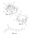
- FIG. 10 is a perspective view of a modified form of mold having textured surfaces along the front and end of the interior of the mold;
- FIG. 11 is a perspective view of the resultant block formed in the mold of FIG. 10 ;
- FIG. 12 is a top plan view of a retaining wall in a serpentine form.
- FIGS. 1-3 a composite concrete or masonry block 10 is illustrated in FIGS. 1-3 and comprises a front textured wall surface 12 and a rear wall surface 14 which is tapered downwardly from a top horizontal surface 16 .
- opposite sidewalls 17 and 18 are generally rectangular or trapezoidal in shape and taper downwardly from the top surface 16 , and along with the front and rear surfaces 12 and 14 terminate in a bottom horizontal surface 20 which is parallel to the top surface 16 . It will be evident by virtue of the downwardly tapered rear surface 14 and sidewall surfaces 17 and 18 which terminate in adjoining relation to the bottom surface 20 that the area or size of the bottom surface is less than the area of the top surface.
- the frontal surface 12 and the bottom surface 20 are upstanding or vertical when the bottom surface 20 is resting upon a horizontal surface, such as, level ground or on the level top surface of a lower adjoining block of a retaining wall as will be hereinafter described.
- the rear surface 14 is formed with a cavity 22 and the bottom surface is formed with a cavity 24 that extends the length of the bottom surface 20 to reduce the weight of each block and facilitate gripping of the rear surface to remove from the mold and for carrying purposes.
- FIGS. 4 and 5 illustrate the utilization of concrete blocks 10 of the present invention in the construction of a retaining wall 30 .
- the finished dimension of each block 10 may be on the order of 16′′ wide by 6′′ high at the front wall surface 12 and 8′′ to 9′′ in depth from the front surface 12 to the rear surface 14 depending upon the depth of the texture and the slope at the rear of the block 10 .
- the voids or cavities 22 and 24 in each block on the rear surface 14 and bottom surface 20 serve to reduce the overall weight of each block 10 by reducing the amount of material required without reducing the overall dimensions of each block.
- the cavity 22 serves as a lifting handle to assist in lifting the retaining wall block from the mold without disturbing the overall dimensions of the block, along with the use of a vacuum to hold the stone while the mold is being removed by hand.
- the mold may also be removed manually by turning the mold over and allowing the block to be removed by gravity pull.
- Blocks can be joined by use of construction adhesives between the layers to prevent movement in relation to one another.
- construction adhesives between the layers to prevent movement in relation to one another.
- the upper edges and adjoining edges will not be completely flush with one another but the chamfered front vertical corners and the wedge shape of the block itself allows for easy configuration of the curved wall.
- the concrete blocks are formed by introduction of a concrete mixture consisting of aggregate sand, cement, water, and water-reducing admixtures, with or without iron oxide color.
- the minimum strength of the concrete is on the order of 4,000 psi.
- Each mold 50 is preferably of a rubber or rubber-like composition having a central cavity 51 of generally trapezoidal configuration defined by a back wall 52 , opposite sides 53 , 54 and a front textured wall 55 , the walls 52 - 54 being tapered on both sides to facilitate ease of removal of the hardened concrete from the rubber mold as well as from a production board B.
- front wall 55 has an inner face of a stone texture which is duplicated from natural stone.
- a raised portion 58 in the bottom wall of the mold is of elongated triangular configuration and is shaped to form the void or cavity 24 extending from end-to-end in each block; and a raised portion 60 in the rear wall 52 is of elongated generally triangular configuration and results in the cavity 22 in the rear surface of each block.
- one or more rubber molds 50 are placed on a standard production board B which can be of various sizes depending upon the manner in which concrete is placed in each mold.
- a standard production board B which can be of various sizes depending upon the manner in which concrete is placed in each mold.
- a BFS SlabFlex® machine Any other type of machinery that produces wet cast products may be used as well.
- Any mold configuration of one or more molds can be mounted on a board B or platform prior to placing concrete in the molds. The molds are positioned so that the textured front wall surface 56 is in a vertical position.
- Support frames 46 are anchored by screws 48 on the production board B in surrounding relation to the mold during concrete placement. The frames 46 are tight enough to prevent the vertical keyways 62 cut in the mold from opening and allowing concrete to leak through the cuts as hereinafter described in more detail.
- a form release agent is applied to the interior of the mold to prevent the concrete from sticking to the mold and prevent bugholes from occurring.
- a water-based release agent is used.
- the inner front wall surface of each mold is surfaced with a different brick or rock orientation. The stone texture may be duplicated from a variety of different styles of natural rock while still maintaining the overall shape of the block.
- the mold may also have a series of intersecting or crossed ridges or ribs 66 projecting inwardly from a common support surface or mat which is secured to the inner front wall surface of the mold.
- the ridges are of sufficient rigidity to resist bending when the concrete is poured into the mold so as to form joints or spacing between the individual bricks or rocks very much similar in appearance to bricks or stones and mortar, and the thickness and depth of each ridge may be varied as illustrated.
- the wet cast machine allows use of multiple colors of concrete to produce a realistic looking natural stone color. A base color with an accent color can be utilized to provide the naturally variegated look of real stone.
- the production board B is then advanced through the filling apparatus for the type of concrete placement equipment that is used to fill the mold with concrete.
- a preferred approach is to fill the mold in the mold cavity by pouring wetcast concrete into the mold cavity.
- the SlabFlex® machine permits use of two or more colors of concrete to produce a realistic looking natural stone color, and the entire matrix of the concrete is colored concrete.
- a base color with an accent color may be used to provide the naturally variegated look of real stone or basic gray concrete without color may be used.
- the production board B is then run through various vibration cycles to densify and level the concrete in the rubber mold followed by smoothing the top surface by use of a hand cement finishing tool and placing the production board B and molds full of concrete in a suitable curing area during the hardening phase which is normally in the range of 12-20 hours depending upon the type of concrete mixture used and the size of the mold.
- each concrete block is removed from the mold and typically is done by hand or using a vacuum demolding device, as shown in FIGS. 8 and 9 .
- This is done by removing the mold and concrete block from the frame 46 using the vacuum, followed by using a manual process and removing the remainder of the concrete block.
- the mold may be peeled off of the textured wall of the mold along the keyways 62 or hinged portions of the mold as shown in FIGS. 8 and 9 . In this way, the textured wall 56 may be manually peeled away from the textured face to preserve the three-dimensional configuration of the textured wall.
- the keyways 62 permit hinging of the rubber mold to facilitate removal of the hardened concrete.
- the rubber molds incorporate a reinforced mesh fabric or strap 64 embedded within the rubber so as to provide reinforcement to the keyways 62 and to prevent tearing at the bottom of the mold. Reversing the mold and allowing the block to be pulled out using gravity is another form of removal. The mold is then placed back into the frames 46 on the production board B.
- the trapezoidal or downwardly tapered configuration of the sidewalls and rear walls greatly facilitate removal of each block along with the formation of voids 22 and 24 , particularly the void or cavity 22 in the rear wall surface.
- the tapering of the sidewalls 17 and 18 rearwardly away from the front wall 12 enables much greater latitude in the formation of each wall into linear, curved, square or rectangular shapes.
- FIGS. 10 and 11 are directed to a modified form of mold 70 which conforms in all respects to the mold 50 and like parts are correspondingly enumerated to the mold illustrated in FIG. 7 .
- the major departure is in the formation of a textured surface at one end 54 ′ and the location of keyways 72 at opposite ends of the front wall 52 ′ opposite to the textured surface in the front wall 55 .
- An additional keyway 74 is formed in the opposite end wall 53 ′ to the textured end surface 54 ′.
- both walls 52 ′ and 53 ′ may be peeled away from the rear wall surface 14 ′ and the end wall opposite to the textured wall surface 54 ′.
- the block 10 ′ is illustrated in FIG.
- the rear surface 14 ′ is formed with a cavity (not shown) and the bottom surface is formed with a cavity that extends a partial length of the bottom surface 20 ′ due to the presence of the sidewall 18 ′.
Abstract
Description
Claims (10)
Priority Applications (4)
| Application Number | Priority Date | Filing Date | Title |
|---|---|---|---|
| US14/176,991 US9758943B1 (en) | 2013-02-08 | 2014-02-10 | Molded concrete blocks having simulated brick or stone outer surfaces and method of making same |
| US15/699,937 US10895055B1 (en) | 2013-02-08 | 2017-09-08 | Molded concrete blocks having simulated brick or stone outer surfaces |
| US15/699,907 US11053656B1 (en) | 2013-02-08 | 2017-09-08 | Method of making molded concrete blocks having simulated brick or stone outer surfaces |
| US17/361,032 US20210395971A1 (en) | 2013-02-08 | 2021-06-28 | Method of making molded concrete blocks having simulated brick or stone outer surfaces |
Applications Claiming Priority (2)
| Application Number | Priority Date | Filing Date | Title |
|---|---|---|---|
| US201361762685P | 2013-02-08 | 2013-02-08 | |
| US14/176,991 US9758943B1 (en) | 2013-02-08 | 2014-02-10 | Molded concrete blocks having simulated brick or stone outer surfaces and method of making same |
Related Child Applications (2)
| Application Number | Title | Priority Date | Filing Date |
|---|---|---|---|
| US15/699,907 Division US11053656B1 (en) | 2013-02-08 | 2017-09-08 | Method of making molded concrete blocks having simulated brick or stone outer surfaces |
| US15/699,937 Division US10895055B1 (en) | 2013-02-08 | 2017-09-08 | Molded concrete blocks having simulated brick or stone outer surfaces |
Publications (1)
| Publication Number | Publication Date |
|---|---|
| US9758943B1 true US9758943B1 (en) | 2017-09-12 |
Family
ID=59752818
Family Applications (4)
| Application Number | Title | Priority Date | Filing Date |
|---|---|---|---|
| US14/176,991 Active US9758943B1 (en) | 2013-02-08 | 2014-02-10 | Molded concrete blocks having simulated brick or stone outer surfaces and method of making same |
| US15/699,907 Active 2034-10-30 US11053656B1 (en) | 2013-02-08 | 2017-09-08 | Method of making molded concrete blocks having simulated brick or stone outer surfaces |
| US15/699,937 Active 2034-03-15 US10895055B1 (en) | 2013-02-08 | 2017-09-08 | Molded concrete blocks having simulated brick or stone outer surfaces |
| US17/361,032 Pending US20210395971A1 (en) | 2013-02-08 | 2021-06-28 | Method of making molded concrete blocks having simulated brick or stone outer surfaces |
Family Applications After (3)
| Application Number | Title | Priority Date | Filing Date |
|---|---|---|---|
| US15/699,907 Active 2034-10-30 US11053656B1 (en) | 2013-02-08 | 2017-09-08 | Method of making molded concrete blocks having simulated brick or stone outer surfaces |
| US15/699,937 Active 2034-03-15 US10895055B1 (en) | 2013-02-08 | 2017-09-08 | Molded concrete blocks having simulated brick or stone outer surfaces |
| US17/361,032 Pending US20210395971A1 (en) | 2013-02-08 | 2021-06-28 | Method of making molded concrete blocks having simulated brick or stone outer surfaces |
Country Status (1)
| Country | Link |
|---|---|
| US (4) | US9758943B1 (en) |
Cited By (4)
| Publication number | Priority date | Publication date | Assignee | Title |
|---|---|---|---|---|
| US20170274556A1 (en) * | 2014-08-15 | 2017-09-28 | Laing O'rourke Australia Pty Limited | Method for Fabricating a Composite Construction Element |
| CN112536912A (en) * | 2020-12-08 | 2021-03-23 | 王光顺 | Production method of building assembly member |
| US20230111563A1 (en) * | 2018-11-29 | 2023-04-13 | Austin Concrete LLC | Imprinting film for a building material and system and method for use of same |
| US11767653B2 (en) * | 2018-03-28 | 2023-09-26 | Tensar International Corporation | Geosynthetic reinforced wall panels comprising soil reinforcing hoop members and retaining wall system formed therewith |
Families Citing this family (1)
| Publication number | Priority date | Publication date | Assignee | Title |
|---|---|---|---|---|
| US20200047373A1 (en) * | 2018-08-13 | 2020-02-13 | Pavestone, LLC | Apparatus for making a masonry block with a roughened surface |
Citations (16)
| Publication number | Priority date | Publication date | Assignee | Title |
|---|---|---|---|---|
| US599786A (en) * | 1898-03-01 | Adolf katz | ||
| US3426122A (en) * | 1968-01-18 | 1969-02-04 | Edmond M Gaudelli | Process for producing stone block structures |
| US3595518A (en) * | 1968-09-16 | 1971-07-27 | Edmond M Gaudelli | Mold bed for molding cementitious products |
| US3883109A (en) * | 1967-10-06 | 1975-05-13 | Pre Cast Concrete Products Lim | Mold for making meter box covers and the like |
| US4647000A (en) * | 1984-05-02 | 1987-03-03 | Hideharu Osada | Flexible mold for forming simulated tile or brick surfaces |
| US20030164574A1 (en) * | 2002-03-04 | 2003-09-04 | James Hammer | Apparatus and methods for making a masonry block with a roughened surface |
| US6616382B2 (en) | 1989-09-28 | 2003-09-09 | Anchor Wall Systems, Inc. | Composite masonry block |
| US20070045897A1 (en) * | 2005-08-23 | 2007-03-01 | Cliff Alexander | Plastic tray for manufacturing a simulated stone product |
| US7267321B1 (en) * | 2003-05-14 | 2007-09-11 | Morrell Kelly J | Wall block mold |
| US20080272132A1 (en) * | 2007-05-03 | 2008-11-06 | Pacific Bin Corporation | Collapsible container |
| US7549616B1 (en) * | 2004-12-21 | 2009-06-23 | Column & Post, Incorporated | Molding device for molding parts |
| US7553109B2 (en) * | 2006-10-04 | 2009-06-30 | Blundell Peter J | High face-area low-volume concrete wall block, form and method |
| US7618578B2 (en) * | 2006-11-21 | 2009-11-17 | Rosetta Hardscapes Llc | Method and apparatus for forming concrete blocks |
| US7687006B2 (en) * | 2006-11-21 | 2010-03-30 | Rosetta Hardscapes, Llc | Form for casting concrete blocks and other objects |
| US7931248B2 (en) * | 2005-12-28 | 2011-04-26 | Boral Stone Products Llc | Flat mold for corner-shaped simulated stone products |
| US8101113B2 (en) * | 2005-04-21 | 2012-01-24 | Oldcastle Building Products Canada, Inc. | Molding apparatus for producing dry cast products having textured side surfaces |
Family Cites Families (37)
| Publication number | Priority date | Publication date | Assignee | Title |
|---|---|---|---|---|
| US1993291A (en) | 1933-05-06 | 1935-03-05 | Vermont Cornelius | Retaining wall |
| DE2731228C2 (en) * | 1977-07-11 | 1983-02-03 | Sf-Vollverbundstein-Kooperation Gmbh, 2820 Bremen | Concrete shaped stone for the production of a retaining wall and retaining wall made of such shaped stones |
| US4512685A (en) | 1981-09-08 | 1985-04-23 | Ameron, Inc. | Mortarless retaining-wall system and components thereof |
| GB8412499D0 (en) * | 1984-05-16 | 1984-06-20 | Cowie A F | Retaining wall block |
| DE8717632U1 (en) * | 1987-04-13 | 1989-08-31 | Hoetzel-Beton Gmbh, 7514 Eggenstein-Leopoldshafen, De | |
| US5843327A (en) * | 1990-06-15 | 1998-12-01 | Lindgren; Haakan | Casting mold device |
| US5161918A (en) | 1991-01-30 | 1992-11-10 | Wedgerock Corporation | Set-back retaining wall and concrete block and offset pin therefor |
| US5066169A (en) * | 1991-02-19 | 1991-11-19 | Gavin Norman W | Retaining wall system |
| US5350256A (en) | 1991-11-26 | 1994-09-27 | Westblock Products, Inc. | Interlocking retaining walls blocks and system |
| US5333427A (en) * | 1992-11-03 | 1994-08-02 | Anchor Hocking Corporation | Decorative utilitarian glass block |
| US5417523A (en) * | 1993-10-29 | 1995-05-23 | Scales; John | Connector and method for engaging soil-reinforcing grid and earth retaining wall |
| US5505034A (en) * | 1993-11-02 | 1996-04-09 | Pacific Pre-Cast Products, Ltd. | Retaining wall block |
| US5622456A (en) * | 1995-03-23 | 1997-04-22 | Rothbury Investments Ltd. | Retaining wall blocks |
| US5788423A (en) * | 1995-09-08 | 1998-08-04 | G.P. Industries, Inc. | Masonry block retaining wall with attached keylock facing panels and method of constructing the same |
| US6224295B1 (en) * | 1996-08-09 | 2001-05-01 | Derrick Ian Peter Price | Soil reinforcement |
| US5820304A (en) | 1997-01-29 | 1998-10-13 | Custom Precast & Masonry, Inc. | Blocks for constructing retaining walls |
| USD403437S (en) * | 1997-06-03 | 1998-12-29 | Rothbury International Inc. | Modular block |
| US5945053A (en) * | 1998-03-13 | 1999-08-31 | Hettinga; Siebolt | Extruded-in fabric hinge and method of making same |
| US6082933A (en) * | 1998-06-09 | 2000-07-04 | Nicolock Of Long Island | Concrete block |
| US6715965B2 (en) * | 1999-09-30 | 2004-04-06 | Redi-Rock International, Llc | Retaining wall blocks and retaining walls constructed from such blocks |
| US6557818B2 (en) * | 1999-09-30 | 2003-05-06 | Redi-Rock International, Llc | Form for manufacturing concrete retaining wall blocks |
| US6827527B2 (en) * | 1999-12-20 | 2004-12-07 | The New Castle Group, Inc. | Wall components and method |
| DE20016658U1 (en) | 2000-09-25 | 2002-02-14 | Karl Weber Betonwerk Gmbh & Co | Step stone for a staircase and stairs made from it |
| US20030070386A1 (en) | 2001-10-16 | 2003-04-17 | Hampton Robert D. | Building block |
| US6884004B1 (en) | 2003-01-13 | 2005-04-26 | Geostar Corporation | Tensile reinforcement-to retaining wall mechanical connection and method |
| US7096634B2 (en) * | 2003-10-24 | 2006-08-29 | Innovative Concrete Design, Inc. | Block wall system |
| DE102004024802A1 (en) * | 2004-05-17 | 2005-12-08 | Sf-Kooperation Gmbh Beton-Konzepte | Retaining wall and concrete block for the production of a retaining wall |
| US20060096180A1 (en) | 2004-10-06 | 2006-05-11 | Price Brian A | Retaining wall block and grid system |
| US20070258776A1 (en) | 2006-04-24 | 2007-11-08 | Strand Todd P | Retaining wall systems |
| US20080095584A1 (en) | 2006-04-24 | 2008-04-24 | Kiltie Corporation | Natural stone simulated surface retaining wall systems |
| US7959380B2 (en) * | 2007-10-11 | 2011-06-14 | Pacific Fence-Crete Ltd. | Landscaping system |
| US8777522B2 (en) * | 2008-01-14 | 2014-07-15 | Micon | Mine seal with multiple mortared walls |
| US20090185870A1 (en) | 2008-01-18 | 2009-07-23 | Shaw Kenneth L | Retaining wall block and method of manufacture |
| US20100133725A1 (en) * | 2008-12-01 | 2010-06-03 | Mccaskey Douglas M | Mold With Reinforced Hinge |
| EP2542723A2 (en) | 2010-03-02 | 2013-01-09 | Keystone Retaining Wall Systems, Inc. | Retaining wall block system |
| US20120057939A1 (en) | 2010-09-07 | 2012-03-08 | Bone Ernest E | Retaining wall block |
| US20120126451A1 (en) * | 2010-11-22 | 2012-05-24 | Owen Robert A | Decorative block |
-
2014
- 2014-02-10 US US14/176,991 patent/US9758943B1/en active Active
-
2017
- 2017-09-08 US US15/699,907 patent/US11053656B1/en active Active
- 2017-09-08 US US15/699,937 patent/US10895055B1/en active Active
-
2021
- 2021-06-28 US US17/361,032 patent/US20210395971A1/en active Pending
Patent Citations (16)
| Publication number | Priority date | Publication date | Assignee | Title |
|---|---|---|---|---|
| US599786A (en) * | 1898-03-01 | Adolf katz | ||
| US3883109A (en) * | 1967-10-06 | 1975-05-13 | Pre Cast Concrete Products Lim | Mold for making meter box covers and the like |
| US3426122A (en) * | 1968-01-18 | 1969-02-04 | Edmond M Gaudelli | Process for producing stone block structures |
| US3595518A (en) * | 1968-09-16 | 1971-07-27 | Edmond M Gaudelli | Mold bed for molding cementitious products |
| US4647000A (en) * | 1984-05-02 | 1987-03-03 | Hideharu Osada | Flexible mold for forming simulated tile or brick surfaces |
| US6616382B2 (en) | 1989-09-28 | 2003-09-09 | Anchor Wall Systems, Inc. | Composite masonry block |
| US20030164574A1 (en) * | 2002-03-04 | 2003-09-04 | James Hammer | Apparatus and methods for making a masonry block with a roughened surface |
| US7267321B1 (en) * | 2003-05-14 | 2007-09-11 | Morrell Kelly J | Wall block mold |
| US7549616B1 (en) * | 2004-12-21 | 2009-06-23 | Column & Post, Incorporated | Molding device for molding parts |
| US8101113B2 (en) * | 2005-04-21 | 2012-01-24 | Oldcastle Building Products Canada, Inc. | Molding apparatus for producing dry cast products having textured side surfaces |
| US20070045897A1 (en) * | 2005-08-23 | 2007-03-01 | Cliff Alexander | Plastic tray for manufacturing a simulated stone product |
| US7931248B2 (en) * | 2005-12-28 | 2011-04-26 | Boral Stone Products Llc | Flat mold for corner-shaped simulated stone products |
| US7553109B2 (en) * | 2006-10-04 | 2009-06-30 | Blundell Peter J | High face-area low-volume concrete wall block, form and method |
| US7618578B2 (en) * | 2006-11-21 | 2009-11-17 | Rosetta Hardscapes Llc | Method and apparatus for forming concrete blocks |
| US7687006B2 (en) * | 2006-11-21 | 2010-03-30 | Rosetta Hardscapes, Llc | Form for casting concrete blocks and other objects |
| US20080272132A1 (en) * | 2007-05-03 | 2008-11-06 | Pacific Bin Corporation | Collapsible container |
Cited By (4)
| Publication number | Priority date | Publication date | Assignee | Title |
|---|---|---|---|---|
| US20170274556A1 (en) * | 2014-08-15 | 2017-09-28 | Laing O'rourke Australia Pty Limited | Method for Fabricating a Composite Construction Element |
| US11767653B2 (en) * | 2018-03-28 | 2023-09-26 | Tensar International Corporation | Geosynthetic reinforced wall panels comprising soil reinforcing hoop members and retaining wall system formed therewith |
| US20230111563A1 (en) * | 2018-11-29 | 2023-04-13 | Austin Concrete LLC | Imprinting film for a building material and system and method for use of same |
| CN112536912A (en) * | 2020-12-08 | 2021-03-23 | 王光顺 | Production method of building assembly member |
Also Published As
| Publication number | Publication date |
|---|---|
| US20210395971A1 (en) | 2021-12-23 |
| US11053656B1 (en) | 2021-07-06 |
| US10895055B1 (en) | 2021-01-19 |
Similar Documents
| Publication | Publication Date | Title |
|---|---|---|
| US20210395971A1 (en) | Method of making molded concrete blocks having simulated brick or stone outer surfaces | |
| US5487526A (en) | Mold device for forming concrete pathways | |
| US5386963A (en) | Form liner | |
| US20040218985A1 (en) | Method of making a composite masonry block | |
| US20110316194A1 (en) | Method And Apparatus For Dry Casting Concrete Blocks Having A Decorative Face | |
| CN104213565A (en) | Die supporting system for large deep pit steep slope surface cushion layer and supporting die casting construction method thereof | |
| US3426122A (en) | Process for producing stone block structures | |
| US8025493B2 (en) | Apparatus for manufacturing a pre-cast retaining wall | |
| US20110185672A1 (en) | Block Moulds and Method | |
| US20120167516A1 (en) | method of forming protrusions on a masonry block | |
| US7918628B1 (en) | Landscaping blocks for forming retaining walls and method of producing landscaping blocks | |
| KR102214348B1 (en) | the improved PC panel unit manufacturing device | |
| US20040123556A1 (en) | Wall unit forming method and apparatus | |
| US3595518A (en) | Mold bed for molding cementitious products | |
| US20090255211A1 (en) | Method and means for producing a concrete block | |
| GB2573293A (en) | Method of casting a textured concrete walling slab | |
| US20090085250A1 (en) | Manufacture of Moulded Paving Elements | |
| WO2007122480A2 (en) | Process for manufacturing building elements for making walls using filling material, particularly earth or the like | |
| US1547530A (en) | Method and apparatus for manufacturing hollow concrete building blocks | |
| EP0096051B1 (en) | Nest-casting of concrete elements | |
| US4784365A (en) | Apparatus for nest-casting of concrete elements | |
| JPH0440165B2 (en) | ||
| JP3079016B2 (en) | Forming method of grooved concrete member and groove pattern forming tool | |
| AU2017268658A1 (en) | Rox in Blox | |
| JPH027018B2 (en) |
Legal Events
| Date | Code | Title | Description |
|---|---|---|---|
| AS | Assignment |
Owner name: PRECAST CONCEPTS, LLC, COLORADO Free format text: ASSIGNMENT OF ASSIGNORS INTEREST;ASSIGNORS:ANDERSON, EDWARD J;PARRINGTON, GEOFFREY S;DEMEYER, DION T;REEL/FRAME:041238/0055 Effective date: 20170201 |
|
| AS | Assignment |
Owner name: NEW PRECAST, LLC, COLORADO Free format text: ASSIGNMENT OF ASSIGNORS INTEREST;ASSIGNOR:PRECAST CONCEPTS, LLC;REEL/FRAME:041477/0910 Effective date: 20170301 |
|
| STCF | Information on status: patent grant |
Free format text: PATENTED CASE |
|
| AS | Assignment |
Owner name: FORTERRA PRECAST CONCEPTS LLC, TEXAS Free format text: ASSIGNMENT OF ASSIGNORS INTEREST;ASSIGNOR:NEW PRECAST LLC;REEL/FRAME:048790/0078 Effective date: 20190319 |
|
| AS | Assignment |
Owner name: BANK OF AMERICA, N.A. (A NATIONAL BANKING INSTITUTION), TEXAS Free format text: SECURITY INTEREST;ASSIGNORS:FORTERRA, INC. (A DELAWARE CORPORATION);FORTERRA PIPE & PRECAST, LLC (A DELAWARE LIMITED LIABILITY COMPANY);BIO CLEAN ENVIRONMENTAL SERVICES, INC. (A CALIFORNIA CORPORATION);AND OTHERS;REEL/FRAME:053228/0967 Effective date: 20200617 Owner name: DEUTSCHE BANK TRUST COMPANY AMERICAS, AS NOTES COLLATERAL AGENT, NEW YORK Free format text: SECURITY AGREEMENT (NOTES);ASSIGNORS:BIO CLEAN ENVIRONMENTAL SERVICES, INC.;FORTERRA CONCRETE PRODUCTS, INC.;GRIFFIN PIPE PRODUCTS COMPANY, LLC;AND OTHERS;REEL/FRAME:053229/0924 Effective date: 20200716 |
|
| AS | Assignment |
Owner name: BANK OF AMERICA, N.A. (A NATIONAL BANKING INSTITUTION), TEXAS Free format text: CORRECTIVE ASSIGNMENT TO CORRECT THE APP 62905899 WHICH WAS ENTERED IN ERROR AND IS TO BE REMOVED FROM THOSE PATENTS PREVIOUSLY RECORDED ON REEL 053228 FRAME 0967. ASSIGNOR(S) HEREBY CONFIRMS THE SECURITY INTEREST.;ASSIGNORS:FORTERRA, INC. (A DELAWARE CORPORATION);FORTERRA PIPE & PRECAST, LLC (A DELAWARE LIMITED LIABILITY COMPANY);BIO CLEAN ENVIRONMENTAL SERVICES, INC. (A CALIFORNIA CORPORATION);AND OTHERS;REEL/FRAME:053246/0963 Effective date: 20200617 |
|
| MAFP | Maintenance fee payment |
Free format text: PAYMENT OF MAINTENANCE FEE, 4TH YEAR, LARGE ENTITY (ORIGINAL EVENT CODE: M1551); ENTITY STATUS OF PATENT OWNER: LARGE ENTITY Year of fee payment: 4 |
|
| AS | Assignment |
Owner name: WELLS FARGO BANK, N.A., AS AGENT, COLORADO Free format text: SECURITY INTEREST;ASSIGNOR:FONTERRA PRECAST CONCEPTS, LLC;REEL/FRAME:059313/0842 Effective date: 20220318 |
|
| AS | Assignment |
Owner name: FORTERRA CONCRETE PRODUCTS, INC., TEXAS Free format text: RELEASE BY SECURED PARTY;ASSIGNOR:DEUTSCHE BANK TRUST COMPANY AMERICAS, AS COLLATERAL AGENT;REEL/FRAME:060199/0286 Effective date: 20220318 Owner name: MODULAR WETLAND SYSTEMS, INC., TEXAS Free format text: RELEASE BY SECURED PARTY;ASSIGNOR:DEUTSCHE BANK TRUST COMPANY AMERICAS, AS COLLATERAL AGENT;REEL/FRAME:060199/0286 Effective date: 20220318 Owner name: FORTERRA PRECAST CONCEPTS, LLC, TEXAS Free format text: RELEASE BY SECURED PARTY;ASSIGNOR:DEUTSCHE BANK TRUST COMPANY AMERICAS, AS COLLATERAL AGENT;REEL/FRAME:060199/0286 Effective date: 20220318 Owner name: BIO CLEAN ENVIRONMENTAL SERVICES, INC., TEXAS Free format text: RELEASE BY SECURED PARTY;ASSIGNOR:DEUTSCHE BANK TRUST COMPANY AMERICAS, AS COLLATERAL AGENT;REEL/FRAME:060199/0286 Effective date: 20220318 Owner name: CUSTOM FAB, INC., TEXAS Free format text: RELEASE BY SECURED PARTY;ASSIGNOR:DEUTSCHE BANK TRUST COMPANY AMERICAS, AS COLLATERAL AGENT;REEL/FRAME:060199/0286 Effective date: 20220318 Owner name: GRIFFIN PIPE PRODUCTS CO., LLC, TEXAS Free format text: RELEASE BY SECURED PARTY;ASSIGNOR:DEUTSCHE BANK TRUST COMPANY AMERICAS, AS COLLATERAL AGENT;REEL/FRAME:060199/0286 Effective date: 20220318 Owner name: UNITED STATES PIPE AND FOUNDRY COMPANY, LLC, TEXAS Free format text: RELEASE BY SECURED PARTY;ASSIGNOR:DEUTSCHE BANK TRUST COMPANY AMERICAS, AS COLLATERAL AGENT;REEL/FRAME:060199/0286 Effective date: 20220318 Owner name: FORTERRA PIPE & PRECAST, LLC, TEXAS Free format text: RELEASE BY SECURED PARTY;ASSIGNOR:DEUTSCHE BANK TRUST COMPANY AMERICAS, AS COLLATERAL AGENT;REEL/FRAME:060199/0286 Effective date: 20220318 Owner name: MODULAR WETLAND SYSTEMS, INC., TEXAS Free format text: RELEASE OF ABL SECURITY INTEREST IN INTELLECTUAL PROPERTY RECORDED AT REEL 053228/FRAME 0967;ASSIGNOR:BANK OF AMERICA, N.A.;REEL/FRAME:059718/0621 Effective date: 20220318 Owner name: FORTERRA PRECAST CONCEPTS, LLC, TEXAS Free format text: RELEASE OF ABL SECURITY INTEREST IN INTELLECTUAL PROPERTY RECORDED AT REEL 053228/FRAME 0967;ASSIGNOR:BANK OF AMERICA, N.A.;REEL/FRAME:059718/0621 Effective date: 20220318 Owner name: UNITED STATES PIPE AND FOUNDRY COMPANY, LLC, TEXAS Free format text: RELEASE OF ABL SECURITY INTEREST IN INTELLECTUAL PROPERTY RECORDED AT REEL 053228/FRAME 0967;ASSIGNOR:BANK OF AMERICA, N.A.;REEL/FRAME:059718/0621 Effective date: 20220318 Owner name: FORTERRA CONCRETE PRODUCTS, INC., TEXAS Free format text: RELEASE OF ABL SECURITY INTEREST IN INTELLECTUAL PROPERTY RECORDED AT REEL 053228/FRAME 0967;ASSIGNOR:BANK OF AMERICA, N.A.;REEL/FRAME:059718/0621 Effective date: 20220318 Owner name: BIO CLEAN ENVIRONMENTAL SERVICES, INC., TEXAS Free format text: RELEASE OF ABL SECURITY INTEREST IN INTELLECTUAL PROPERTY RECORDED AT REEL 053228/FRAME 0967;ASSIGNOR:BANK OF AMERICA, N.A.;REEL/FRAME:059718/0621 Effective date: 20220318 Owner name: FORTERRA PIPE & PRECAST, LLC, TEXAS Free format text: RELEASE OF ABL SECURITY INTEREST IN INTELLECTUAL PROPERTY RECORDED AT REEL 053228/FRAME 0967;ASSIGNOR:BANK OF AMERICA, N.A.;REEL/FRAME:059718/0621 Effective date: 20220318 |
|
| AS | Assignment |
Owner name: WELLS FARGO BANK, NATIONAL ASSOCIATION, AS AGENT, GEORGIA Free format text: PATENT SECURITY AGREEMENT (ABL);ASSIGNORS:UNITED STATES PIPE AND FOUNDRY COMPANY, LLC;GRIFFIN PIPE PRODUCTS CO., LLC;CUSTOM FAB, INC.;AND OTHERS;REEL/FRAME:059479/0437 Effective date: 20220318 Owner name: WELLS FARGO BANK, NATIONAL ASSOCIATION, AS AGENT, GEORGIA Free format text: PATENT SECURITY AGREEMENT (ABL);ASSIGNORS:UNITED STATES PIPE AND FOUNDRY COMPANY, LLC;GRIFFIN PIPE PRODUCTS CO., LLC;CUSTOM FAB, INC.;AND OTHERS;REEL/FRAME:059479/0336 Effective date: 20220318 |