US9744274B2 - Tissue sampling, processing and collection device and method of using same - Google Patents
Tissue sampling, processing and collection device and method of using same Download PDFInfo
- Publication number
- US9744274B2 US9744274B2 US13/315,232 US201113315232A US9744274B2 US 9744274 B2 US9744274 B2 US 9744274B2 US 201113315232 A US201113315232 A US 201113315232A US 9744274 B2 US9744274 B2 US 9744274B2
- Authority
- US
- United States
- Prior art keywords
- tissue
- collection
- processing
- fat
- syringe
- Prior art date
- Legal status (The legal status is an assumption and is not a legal conclusion. Google has not performed a legal analysis and makes no representation as to the accuracy of the status listed.)
- Active, expires
Links
Images


Classifications
-
- A61M1/0058—
-
- A—HUMAN NECESSITIES
- A61—MEDICAL OR VETERINARY SCIENCE; HYGIENE
- A61B—DIAGNOSIS; SURGERY; IDENTIFICATION
- A61B10/00—Other methods or instruments for diagnosis, e.g. instruments for taking a cell sample, for biopsy, for vaccination diagnosis; Sex determination; Ovulation-period determination; Throat striking implements
- A61B10/02—Instruments for taking cell samples or for biopsy
- A61B10/0233—Pointed or sharp biopsy instruments
- A61B10/0283—Pointed or sharp biopsy instruments with vacuum aspiration, e.g. caused by retractable plunger or by connected syringe
-
- A—HUMAN NECESSITIES
- A61—MEDICAL OR VETERINARY SCIENCE; HYGIENE
- A61M—DEVICES FOR INTRODUCING MEDIA INTO, OR ONTO, THE BODY; DEVICES FOR TRANSDUCING BODY MEDIA OR FOR TAKING MEDIA FROM THE BODY; DEVICES FOR PRODUCING OR ENDING SLEEP OR STUPOR
- A61M1/00—Suction or pumping devices for medical purposes; Devices for carrying-off, for treatment of, or for carrying-over, body-liquids; Drainage systems
- A61M1/89—Suction aspects of liposuction
- A61M1/892—Suction aspects of liposuction with treatment of the collected fat
-
- A—HUMAN NECESSITIES
- A61—MEDICAL OR VETERINARY SCIENCE; HYGIENE
- A61M—DEVICES FOR INTRODUCING MEDIA INTO, OR ONTO, THE BODY; DEVICES FOR TRANSDUCING BODY MEDIA OR FOR TAKING MEDIA FROM THE BODY; DEVICES FOR PRODUCING OR ENDING SLEEP OR STUPOR
- A61M1/00—Suction or pumping devices for medical purposes; Devices for carrying-off, for treatment of, or for carrying-over, body-liquids; Drainage systems
- A61M1/89—Suction aspects of liposuction
- A61M1/895—Suction aspects of liposuction with means for reinjection of collected fat
-
- A—HUMAN NECESSITIES
- A61—MEDICAL OR VETERINARY SCIENCE; HYGIENE
- A61M—DEVICES FOR INTRODUCING MEDIA INTO, OR ONTO, THE BODY; DEVICES FOR TRANSDUCING BODY MEDIA OR FOR TAKING MEDIA FROM THE BODY; DEVICES FOR PRODUCING OR ENDING SLEEP OR STUPOR
- A61M1/00—Suction or pumping devices for medical purposes; Devices for carrying-off, for treatment of, or for carrying-over, body-liquids; Drainage systems
- A61M1/71—Suction drainage systems
- A61M1/77—Suction-irrigation systems
Definitions
- the present invention relates to improvements in methods of and apparatus for sampling, processing and collecting tissue samples using aspiration processes.
- adipose i.e. fat
- musculoskeletal i.e. bone, ligament, cartilage and skin
- autologous adipose tissue transplantation involves the procurement of adipose tissue by liposuction techniques from an area of abundance, and re-injection of the harvested adipose tissue into a different site of the same individual for cosmetic/reconstructive augmentation or enhancement purposes.
- adipose tissue must be as ‘clean’ or refined as possible before re-introduction to maximize the chances of graft survival. Such refinement preferably is done with as little exposure of the tissue to air as possible (i.e., “anaerobic tissue handling”).
- U.S. Pat. No. 6,316,247 to Katz et al discloses a method of and apparatus for separating adipose tissue for autologous tissue transplantation.
- Liposuctioned tissue removed from the patient is transferred into the device through the inlet port that is contiguous with the inner flexible porous container.
- Pieces of adipose tissue are “trapped” within the inner flexible container whereas waste components (free oil, blood, serum) are able to drain through the pores and out the outlet port.
- waste components free oil, blood, serum
- the trapped tissue may be rinsed thoroughly with saline or buffer. For very thorough cleansing, the outlet port is sealed, buffer is added, and the inlet port is sealed.
- the device is agitated to encourage thorough rinsing of the tissue, and then the device is held upright and the bottom outlet port unsealed to allow for drainage of waste or active suction of the effluent. This step can be repeated several times as necessary to achieve tissue that is highly “purified”.
- the washed tissue can be expressed from the inner flexible container by ‘rolling’ the tissue out through the inlet port (from bottom to top) into receptacles, e.g., syringes, for re-implantation or any other desired receptacle for further preparation before injection.
- a receptacle can be attached directly to the port such that the tissue can be anaerobically re-injected into the body.
- Another object of the present invention is to provide a new tissue sampling, processing and injection syringe device which avoids the shortcomings and drawbacks of the prior art apparatus and methodologies.
- Another object of the present invention is to provide an improved method of harvesting a tissue sample from a patient or donor using the tissue sampling, processing and injection syringe device.
- Another object of the present invention is to provide an improved method of harvesting, processing and injecting a tissue sample into a patient using the tissue sampling, processing and injection syringe device.
- Another object of the present invention is to provide an improved in-line three-pack tissue sampling, processing and collection device.
- Another object of the present invention is to provide an improved method of processing aspirated tissue during harvesting using the 3-pack tissue sampling, processing and collection device of the present invention, coupled in-line to a hand-held powered tissue aspiration instrument.
- Another object of the present invention is to provide an improved method of injecting processed tissue samples into a patient using a fat-filled tissue injection syringe device.
- Another object of the present invention is to provide an improved method of harvesting, processing and injecting a tissue sample into a patient using the tissue sampling, processing and injection syringe device.
- Another object of the present invention is to provide an improved in-line six-pack tissue sampling, processing and collection device.
- Another object of the present invention is to provide an improved method of processing aspirated tissue during harvesting using the six-pack tissue sampling, processing and collection device
- Another object of the present invention is to provide an improved method of injecting processed tissue into a patient using a fat-filled tissue injection syringe device.
- Another object of the present invention is to provide an improved method of harvesting, processing and injecting a tissue sample into a patient using the tissue sampling, processing and injection syringe device.
- Another object of the present invention is to provide improved tissue sampling, processing and collection devices which can be designed for single-use, as sterile consumables with a high profit margin.
- Another object of the present invention is to provide improved tissue sampling, processing and collection devices which can be easily integrated with stem cell storage banks and cellular differentiation and enrichment programs.
- Another object of the present invention is to provide improved tissue sampling, processing and collection devices which obviate the need for decanting, tissue transfers, autoclaving, or straining operations.
- Another object of the present invention is to provide improved tissue sampling, processing and collection devices which enable gentle tissue harvesting operations, without heat, tissue trauma, blood loss, or surgeon effort.
- Another object of the present invention is to provide a tissue sampling, collection, processing and re-injection system employing the modular and disposable tissue collection components which can be used in both manually-powered and vacuum-powered tissue sampling, processing and collection systems, providing significant levels of improvement in flexibility, convenience, and economy.
- Another object of the present invention is to provide improved tissue sampling, processing and collection methods which work with both integrated and independent single-use sterile devices for aspirating, collecting, selectively sampling, processing, and re-injecting tissue.
- Another object of the present invention is to provide such tissue sampling, processing and collection methods which can be practiced using low vacuum aspiration pressures, to minimize cellular rupture and oils.
- Another object of the present invention is to provide improved tissue sampling, processing and collection methods, wherein aspirated and collected fat tissue is gently cleaned by tumescent fluid used during tissue aspiration operations, and wherein fluids and oils within tissue aspirants filtered through non-occluded micro-pores formed in tissue collection tubes employed in the apparatus.
- Another object of the present invention is to provide improved tissue sampling, processing and collection methods which lavage harvested fat cells within the tissue collection apparatus of the present invention, along with an insulin or a growth factor enriched solution aspirated during tissue aspiration operations.
- Another object of the present invention is to provide improved tissue sampling, processing and collection methods which result in lower cellular injury leading to higher graft survival rates.
- Another object of the present invention is to provide improved tissue sampling, processing and collection methods, wherein collected tissue autografts can be stored for up to two years in an ordinary freezer (2-3° F.) without requiring cryopreservation.
- Another object of the present invention is to provide improved tissue sampling, processing and collection platform which provides an autograft concentrate for an integrated banking program with optional further processing of adipocytes and stem cells.
- Another object of the present invention is to provide improved tissue sampling, processing and collection methods which can be used for treating: facial wrinkles; scars and over-treated areas; Romberg's hemifacial atrophy; AIDS wasting; microsomia; facial revoluminization and youthfulization; breast augmentation; breast reconstruction; butt augmentation; and calf augmentation.
- Another object of the present invention is to provide improved tissue sampling, processing and collection methods which minimize allergy or rejection from autograft.
- Another object of the present invention is to provide improved tissue sampling, processing and collection methods which allow living tissue to provide better and more sustained results.
- Another object of the present invention is to provide improved tissue sampling, processing and collection methods which help to “reboot” the face with non-apoptotic primitive precursor adipocytes and stem cells.
- Another object of the present invention is to provide improved tissue sampling, processing and collection methods which can be used in mesotherapy volume restoration to lessen sagging and youthen skin tissue.
- Another object of the present invention is to provide improved tissue sampling, processing and collection methods which may be used with power assisted injector guns.
- Another object of the present invention is to provide improved tissue sampling, processing and collection methods which can be used in conjunction with multi-needle injectors and rollers.
- Another object of the present invention is to provide a more efficient, versatile, cost-effective, sterile method and system for refining adipose tissue samples for immediate transplantation.
- Another object of the present invention is to provide improved tissue sampling, processing and collection devices which are realized as disposable, single use small volume collection, processing and reinjection devices for manual subcutaneous tissue sampling and re-injection
- Another object of the present invention is to provide improved reusable small, medium and large volume collection, processing, and reinjection devices employing single use disposable components.
- Another object of the present invention is to provide improved tissue sampling, processing and collection devices for use in bone marrow harvesting & processing operations carried out intra-operatively on live patient donors, or on deceased human donors on a post-mortem basis.
- Another object of the present invention is to provide disposable, single use small volume manual collection, processing and reinjection devices.
- Another object of the present invention is to provide reusable small, medium and large volume collection, processing, and reinjection devices that are used in conjunction with air or electrically powered hand-held tissue aspiration instruments, and also employing single use disposable components.
- Another object of the present invention is to provide a disposable device for the refinement of adipose tissue.
- Another object of the present invention is to provide a more efficient, cost-effective, sterile method and system that overcomes the deficiencies of prior devices and systems for the refinement of adipose tissue for autologous adipose transplantation.
- Another object of the present invention is to provide surgeons with an improved method of and apparatus for harvesting tissue for autologous adipose transplantation.
- Another object of the present invention is to provide an improved method and apparatus of harvesting, processing and collecting tissue for use in immediate clinical applications, as well as support of individuals engaged in cell-based science, developmental biology, tissue engineering research and genetic engineering.
- FIG. 1 is a graphical illustration showing the various phases of tissue sampling, collection, processing and re-injection using the devices and methods of the present invention
- FIG. 2 is a perspective view of an illustrative embodiment of the tissue sampling, processing and injection syringe device of the present invention, to which a cannula is connected via a Leur locking connector;
- FIG. 2 A 1 is a perspective view of a tissue collection tube employed in the tissue sampling, processing and collection devices of the present invention shown in FIGS. 9B and 13C , comprising a distal end opening for receipt of a distal tip capping element (i.e. cap), an proximal end opening for receiving a rubber plunger connected to a push shaft (or piston) shown in FIG. 2 A 2 , and two sets of micro-pores formed along one side of the collection tube for allowing fluids to pass therethrough and concentrating cellular material, when un-occluded by the rotatable micro-pore occluder shown in FIG. 2 ;
- a distal tip capping element i.e. cap
- a rubber plunger connected to a push shaft (or piston) shown in FIG. 2 A 2
- two sets of micro-pores formed along one side of the collection tube for allowing fluids to pass therethrough and concentrating cellular material, when un-occluded by the rotatable micro-pore occluder shown in FIG
- FIG. 2 A 2 is a perspective view of a rubber plunger connected to a push shaft (i.e. piston), which is adapted to slide into the interior volume of the tissue collection tube shown in FIG. 2 A 1 ;
- a push shaft i.e. piston
- FIG. 2 A 3 is a perspective view of the micro-pore occluder that slides on and fits about the tissue collection tube shown in FIG. 2 A 1 , and which can be rotatably configured to occlude the micro-pores in its occluded state, or allow the micro-pores to remain exposed and open to the ambient environment;
- FIG. 2 A 4 is a perspective view of the cap adapted to fit over and close off (i.e. create fluid seal over) the distal end opening or tip of the tissue collection tube shown in FIG. 2 A 1 ;
- FIG. 3 is a perspective view showing the assembly of the components of the tissue sampling, processing and injection syringe device of the present invention, depicted in FIGS. 2, 7A, 11A, and 15A ;
- FIG. 4A is a perspective view of the tissue sampling, processing and injection syringe device of the present invention, shown configured with its micro-pores arranged in its occluded state;
- FIG. 4B is a perspective view of the tissue sampling, processing and injection syringe device of the present invention, shown configured with its micro-pores arranged in its non-occluded state;
- FIG. 5 is a flow chart describing the primary steps carried out when practicing the method of harvesting a tissue sample from a patient or donor using the tissue sampling, processing and injection syringe device of the present invention, shown in FIGS. 2 through 4B ;
- FIG. 5A is a partially cut-away perspective view of the tissue sampling, processing and injection syringe device of FIG. 2 , showing its cap being removed from its distal end opening;
- FIG. 5B is a perspective view of the tissue sampling, processing and injection syringe device of FIG. 2 , showing its occluder being slid down its collection barrel and rotating same to cover the micro-pores of the tissue sampling, processing and injection syringe device of the present invention;
- FIG. 5C is a perspective view of the tissue sampling, processing and injection syringe device of FIG. 2 , showing a cannula being attached to the distal end opening of the collection barrel;
- FIG. 5 D 1 is a perspective view of the tissue sampling, processing and injection syringe device of FIG. 2 , showing its plunger being drawn back from the tissue sampling, processing and injection syringe device (from state 1 to state 2 ) to create vacuum pressure within the tissue collection tube and aspirate a sample of fat tissue therein;
- FIG. 5 D 2 is a perspective view of the tissue sampling, processing and injection syringe device of FIG. 2 , being used to aspirate fat tissue sample, by surgeon inserting the syringe device, with micro-pores occluded, and cannula mounted, into desired donor or treatment site, and maintaining backward pressure on plunger/piston to create vacuum, and aspirate a sample of fat tissue from a patient or donor;
- FIG. 5E is a perspective view of the tissue sampling, processing and injection syringe device of FIG. 2 , shown filled with fat tissue;
- FIG. 6 is a flow chart describing the primary steps carried out when practicing the method of processing aspirated tissue sample using the tissue sampling, processing and injection syringe device of the present invention shown in FIG. 2 ;
- FIG. 6A is a perspective view of the tissue sampling, processing and injection syringe device of FIG. 2 , shown with its cannula removed and its distal end opening capped;
- FIGS. 6 B 1 through 6 B 6 set forth a series of illustrations showing the tissue sampling, processing and injection syringe device of FIG. 2 being manually reconfigured from (i) its occluded state shown in FIG. 6 B 1 , during which a sample of tissue can be aspirated/sampled into the collection tube when the plunger is manually withdrawn from its collection barrel while its micro-pores are occluded (i.e. blocked) and ejected from the collection tube when the plunger is pushed into the collection tube while the micro-pores are occluded, into (ii) its non-occluded state shown in FIG.
- FIG. 6C is a perspective view of the tissue sampling, processing and injection syringe device of FIG. 2 , shown being used to concentrate a fat tissue sample within the collection tube by manually pushing its plunger into the collection tube while the micro-pores in the collection tube are in a non-occluded state, allowing fluid in the tissue sample to be expressed (i.e. filtered) through the non-occluded micro-pores and the collected tissue sample to be concentrated for re-injection into the patient, or subsequent processing at a tissue bank;
- FIG. 6D is perspective view of the tissue sampling, processing and injection syringe device of the present invention, showing its plunger being manually pushed into the collection tube while the micro-pores in the collection tube are in a non-occluded state, allowing fluid in the tissue sample to be expressed through the non-occluded micro-pores and the collected tissue sample to be concentrated for rejection into the patient or subsequent processing at a tissue bank;
- FIG. 7 is a flow chart describing the primary steps carried out when practicing the method of injecting processed tissue into a patient using the tissue sampling, processing and injection syringe device of FIG. 2 ;
- FIG. 7A is a perspective view of the tissue sampling, processing and injection syringe device of the present invention, showing a cannula being installed on its distal end opening, connected using a Leur lock connector;
- FIG. 7B is a perspective view of the tissue sampling, processing and injection syringe device of the present invention, shown configured for injecting fat tissue sample into a patient, by depressing the plunger piston while the micro-pores are arranged in the occluded state;
- FIG. 7C is a perspective view of a patient having a tissue sample injected beneath her skin a surgeon using the tissue sampling, processing and injection syringe device of the present invention
- FIG. 7D is a perspective view of the tissue sampling, processing and injection syringe device of the present invention, shown configured in a state after the surgeon completes the injection of the fat tissue sample into the patient;
- FIG. 8 is a flow chart describing the primary steps carried out when practicing the method of harvesting, processing and injecting a tissue sample into a patient using the tissue sampling, processing and injection syringe device of the present invention, depicted in FIGS. 1 through 7D ;
- FIG. 9 is a flow chart describing the primary steps involved when practicing the method of harvesting tissue samples from a patient using the 3-pack tissue sampling, processing and collection device of the present invention shown in FIGS. 9A and 9B , being connected in-line with hand-held tissue aspiration instrument;
- FIG. 9A is a perspective view of the 3-pack tissue sampling, processing and collection device of the present invention being prepared for connection in-line with a hand-held power-assisted tissue aspiration instrument, by removing its barbed connector for connection of the 3-pack tissue sampling, processing and collection device:
- FIG. 9B is a perspective exploded view of the 3-pack tissue sampling, processing and collection device of FIG. 9A , shown comprising a lid with a barbed connector (provided on the vacuum side), a 3-syringe base plate suction mount for mounting three syringe collection tubes, and a chamber with a screw-on connector to mount directly on rear of hand-held tissue aspiration instrument;
- FIG. 9C is a perspective view of the 3-pack tissue sampling, processing and collection device of the present invention shown completely assembled, and connected to a hand-supportable power-assisted tissue aspiration instrument;
- FIG. 9D is a perspective exploded view of the 3-pack tissue sampling, processing and collection device of the present invention, connected to a vacuum source by way of the hand-supportable power-assisted tissue aspiration instrument, while aspirating tissue samples from a patient, and filtering the same during aspiration to produce concentrated tissue prepared for immediate re-injection into the patient, or subsequent processing at a tissue bank;
- FIG. 9E is a cross-sectional diagram of the 3-pack tissue sampling, processing and collection device shown in FIG. 9D , illustrating how aspirated tissue flows from the input side, through the micro-pores formed in the walls of the tissue collection tubes mounted within the device, and out through the vacuum source side of the system, to leave concentrated tissue samples in the collection tubes, prepared for immediate reinjection into the body of the donor patient, or other patient requiring tissue injection;
- FIG. 10 is a flow chart describing the steps carried out when practicing the method of processing aspirated tissue during harvesting using the 3-pack tissue sampling, processing and collection device of the present invention, coupled in-line to a hand-held powered tissue aspiration instrument;
- FIG. 10A is a perspective view of the 3-pack tissue sampling, processing and collection device shown in FIG. 9D , being detached from the hand-supportable powered tissue aspiration instrument;
- FIG. 10B is a perspective view of the 3-pack tissue sampling, processing and collection device shown in FIG. 9D , shown with its lip being removed to provided access to the tissue-filled collection tubes contained within the container housing;
- FIG. 10C is a perspective view showing the removal of the tissue collection tubes from the 3-pack tissue sampling, processing and collection device of the present invention.
- FIG. 11 is a flow chart describing the primary steps carried out when practicing the method of injecting processed tissue samples into a patient using a fat-filled tissue injection syringe device of present invention assembled using a fat-filled tissue collection tube from the device of FIG. 10A , to be converted into the tissue injection syringe device shown in FIG. 2 ;
- FIG. 11A is a perspective view of a fat-filled tissue injection syringe device of present invention, constructed by attaching a micro-pore occluder to a fat-filled collection tube removed from the dissembled 3-pack tissue sampling, processing and collection device of FIG. 10C to occlude its micro-pores, and then inserting a plunger and piston into the proximal end opening of the collection tube (i.e. barrel), and finally attaching a cannula to the distal end opening of the collection tube, by way of a Leur locking connector assembly;
- FIG. 11B is a perspective view of the fat-filled tissue injection syringe device of present invention constructed in FIG. 11A , shown being used by a surgeon to inject tissue into a patient by depressing the piston into the collection tube while its micro-pores are in their occluded state;
- FIG. 11C is a perspective view of the fat-filled tissue injection syringe device of present invention being used to inject processed tissue back into the patient to achieve a desired achieve correction;
- FIG. 11D is a perspective view of the tissue injection syringe device of FIG. 11D after it has been emptied of its tissue sample;
- FIG. 12 is a flow chart describing the primary steps carried out when practicing the method of harvesting, processing and injecting a tissue sample into a patient using the tissue sampling, processing, collection and injection device, depicted in FIGS. 9 through 11D ;
- FIG. 13 is a flow chart describing the primary steps carried out when practicing the method of sampling aspirated tissue samples using 6-pack tissue sampling, processing and collection device of the present invention, shown in FIGS. 13A and 13B , allowing the surgeon to select which collection tubes to fill at any given moment, while coupled in-line with a hand-held tissue aspiration instrument;
- FIG. 13A is a first perspective view of the 6-pack tissue sampling, processing and collection device of the present invention shown completely assembled, adapted for in-line connection with a hand-held power-assisted tissue aspiration instrument, and having six separate tissue collection tubes (i.e. chambers) which may be independently selected by the surgeon, by the manual rotation of the selector knob, and then filled with tissue biopsy or aspirate from different areas within a patient during surgical operations;
- tissue collection tubes i.e. chambers
- FIG. 13B is a second perspective view of the 6-pack tissue sampling, processing and collection device shown in FIG. 13A ;
- FIG. 13C is a first exploded perspective view of the 6-pack tissue sampling, processing and collection device shown in FIGS. 13A and 13B , shown comprising a collection chamber, a lid with barbed connector for connection to the suction tubing, a suction plate having six projections for supporting six tissue collection tubes (i.e. within the collection chamber), a selector with a passageway/flowpath extending from the center of the chamber to periphery thereof to control the flow of aspirated fat sample into the selected tissue collection tube, and a barbed connector for connecting to tubing extending to the hand-supportable tissue aspiration instrument, and a spring pushing up the turning knob and keeping the selector at the bottom of the collection chamber;
- FIG. 13D is a second exploded perspective view of the 6-pack tissue sampling, processing and collection device shown in FIGS. 13A, 13B and 13C ;
- FIG. 13E is a cross-sectional view of the in-line tissue sampling, processing and collection device shown in FIGS. 13A through 13D , illustrating the passage of aspirated tissue within the selector component, extending from the center of the device to the periphery thereof to control the flow of aspirated fat samples into the selected syringe;
- FIG. 13F is a perspective view of the six-pack tissue sampling, processing and collection device connected to a hand-held power-assisted tissue aspiration instrument of the present invention by way of a second of flexible tubing;
- FIG. 13G is perspective view of the six-pack tissue sampling, processing and collection device and hand-held power-assisted tissue aspiration instrument shown in FIG. 13F , being used to aspirate tissue samples from a patient;
- FIG. 13H is a cross-sectional view of the in-line tissue sampling, processing and collection device shown in FIG. 13G , illustrating the flow of an aspirated tissue sample from the patient, through the fat aspiration instrument, to the selector component of the tissue sampling, processing and collection device, through the passageway/flow director, into the selected tissue collection tube, whereupon fat cells are collected within the selected collection tube while excess fluid (i.e. serum and tumescent solution) is expressed through micro-pores (i.e. perforations or fine holes) in the selected tissue collection tube, and passed out through the barded connector towards to vacuum source, leaving cellular components behind because concentrated adipocytes and stem cells are too big to pass through micro-pores and remain within collection tube;
- excess fluid i.e. serum and tumescent solution
- FIG. 14 is a flow chart describing the primary steps carried out when practicing the method of processing aspirated tissue during harvesting using the six-pack tissue sampling, processing and collection device of the present invention, shown in FIGS. 13A and 13B ;
- FIG. 14A is a perspective view of the six-pack tissue sampling, processing and collection device of the present invention, showing its collection lid being removed after the device has been disconnected from the hand-hand power-assisted tissue aspiration instrument shown in FIG. 13F ;
- FIG. 14B is a perspective view of the six-pack tissue sampling, processing and collection device of the present invention, showing the removal of the tissue collection tube suction plate from the collection chamber of the six-pack tissue sampling, processing and collection device;
- FIG. 14C is a perspective view of the six-pack tissue sampling, processing and collection device of the present invention, showing the detachment of the tissue collection tubes (i.e. syringe barrels) from the tissue collection tube suction plate;
- tissue collection tubes i.e. syringe barrels
- FIG. 15 is a flow chart describing the primary steps carried out when practicing the method of injecting processed tissue into a patient using a fat-filled tissue injection syringe device of the present invention which is constructed by attaching a flanged occluder to the tissue collection tube and inserting a plunger and piston into the proximal end opening of the tissue collection tube, shown in FIGS. 3, 5C , and 15 A;
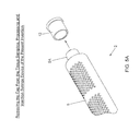
- FIG. 15A is a perspective view of a fat-filled tissue injection syringe device of present invention, constructed by attaching a micro-pore occluder to a fat-filled collection tube removed from the dissembled 6-pack tissue sampling, processing and collection device of FIGS. 13A through 13C to occlude its micro-pores, and then inserting a plunger and piston into the proximal end opening of the collection tube (i.e. barrel), and finally attaching a cannula to the distal end opening of the collection tube, by way of a Leur locking connector assembly;
- FIG. 15B is a perspective view of the fat-filled tissue injection syringe device of present invention constructed in FIG. 15A , shown being used by a surgeon to inject tissue into a patient by depressing the piston into the collection tube while its micro-pores are in their occluded state;
- FIG. 15C is a perspective view of the fat-filled tissue injection syringe device of present invention being used to inject processed tissue back into the patient to achieve a desired achieve correction;
- FIG. 15D is a perspective view of the tissue injection syringe device of FIG. 15D after it has been emptied of its tissue sample.
- FIG. 16 is a flow chart describing the primary steps carried out when practicing the method of harvesting, processing and injecting a tissue sample into a patient using the tissue sampling, processing, collection and injection devices of the present invention, depicted in FIGS. 13 through 15D .
- FIG. 1 shows the various phases of tissue sampling, collection, processing and re-injection using the modular devices and methods of the present invention disclosed herein, wherein modular, disposable tissue aspiration, processing, collection and/or re-injection components can be used in different tissue sampling, processing and collection system designs, providing significant improvements in flexibility, convenience, and economy.
- 3D computer imaging techniques are typically used to survey a patient's body contour and plan out fat tissue transplantation for corrective purposes.
- tissue is harvested in small volumes from the patient/donor using the tissue sampling, processing and injection syringe device 2 with cannula 3 , forming device 1 , shown and described FIGS. 2 through 5E .
- tissue is harvested in medium or large volumes using either 3-pack tissue sampling, processing and collecting device of the present invention shown in FIGS. 9A through 9E , or the 6-pack tissue sampling, processing and collecting device of the present invention shown in FIGS. 13A through 13F , each being connected in-line to outlet port of a hand-supportable power-assisted tissue aspiration instrument 10 as disclosed in Applicant's copending U.S. application Ser. Nos. 12/850,786, 12/462,596 and 12/813,067, incorporated herein by reference.
- fat tissue is collected in individual tissue collection tubes 5 having micro-pores 6 which are selectively occluded or non-occluded simply by rotation of a micro-pore occluder 7 that snap fits about the tissue collection tube, as shown in FIGS. 3 and 5B .
- a single tissue collection tube 5 is filled with fat tissue during manually powered aspiration operations, illustrated in FIGS. 5 D 1 , 5 D 2 , and 5 E.
- the multiple tissue collection tubes 5 shown in FIG. 2 A 1 , without a micro-occluder 7 installed, are supported on the mounting posts of (i) suction mounting plate 38 within the collection chamber of the 3-pack device 30 shown in FIGS. 9B and 10C , and (ii) suction plate 68 within the collection chamber of the 6-pack device shown in FIGS. 13C and 14C .
- each tissue collection tube 5 used to construct the tissue sampling, processing and injection syringe device of FIG. 2 is also used in multiples within the 3-pack and 6-pack tissue sampling, processing and collection devices of FIGS. 9A and 13A .
- the tissue collection tube 5 has the appearance of a syringe barrel, with micro-pores 6 formed in the tube walls normally open for fluid filtration therethrough during tissue collection operations.
- Each tissue collection tube 5 has a distal end opening 5 A adapted to receive a cannula 3 via a Leur lock connector fitting 4 , and a proximal end opening 5 B adapted to receive a plunger 8 A and piston 8 B subassembly 8 .
- Each tissue collection tube 5 is also adapted with a flange 9 having opposite flat side edge surfaces 9 A and 9 B, for engagement with a flat rectangular flange 11 extending from the micro-pore occluder 7 , as shown in FIGS. 2 A 2 and 3 .
- the micro-pore occluder 7 is slid around and rotatable about the tissue collection tube, in either one of two possible configurations.
- tissue can be aspirated into the tissue collection tube.
- a cap 12 is applied to the distal tip of the tissue collection tube 5 and pressure is applied against a collected tissue sample in the tissue collection tube (i.e. by pushing its plunger and piston into the tissue collection tube), fluid is expressed out of the micro-pores 6 formed in the side walls of the tissue collection tube, filtering and concentrating the cellular in situ within the collection tube.
- tissue samples have been collected and processed within individual tissue collection tubes within the collection chamber of multi-pack tissue sampling, processing and collection device 30 or 60 .
- a first option is to readily adapt each tissue-filled collection tube into a tissue injection syringe device by capping their distal end openings with cap 12 , and inserting a plunger piston 8 partially into the proximal end openings thereof. Then these tissue-filled injection syringe devices 2 can be placed in autograft storage, or used immediately in autograft tissue re-injection procedures by simply removing the cap from the distal end opening of the syringe device and connecting a cannula thereto via Leur locking mechanism.
- the tissue collection tubes, filled with filtered and concentrated cellular material can be subjected to further processing and cellular concentration, prior to being place in autograft storage. Thereafter, the tissue collection tubes can be removed from autograft storage and used in autograft tissue re-injection procedures.
- 3D computer imaging is used again to see how closely the surgeon was able to achieve planned body sculpting during a first round of surgery. If necessary, the surgeon can repeat the phases indicated in FIG. 1 to achieve desired results.
- FIG. 2 shows an illustrative embodiment of the tissue sampling, processing and injection syringe device of the present invention 2 , to which a cannula 3 is connected via a Leur locking connector 4 .
- the components of this syringe device 2 are shown in FIGS. 2A through 2D , as comprising: tissue collection tube 5 having (i) distal end opening 5 A for receipt of distal tip capping element (i.e. cap) 12 , (ii) proximal end opening 5 B and (iii) interior volume 5 C; a rubber plunger 8 A connected to a push shaft (or piston) 8 B shown in FIG.
- micro-pore occluder 7 sliding on and fitting about the tissue collection tube 5 , and being rotatably configured to occlude its micro-pores 6 in its occluded state, or allow its micro-pores 6 to remain exposed and open to the ambient environment; and cap 12 adapted to fit over and close off (i.e. create fluid seal over) the distal end opening 5 A, or tip portion of the tissue collection tube shown in FIG. 2A .
- FIG. 3 shows the components of the tissue sampling, processing and injection syringe device 2 , depicted in FIGS. 2, 7A, 11A, and 15A , being assembled in accordance with the principles of the present invention.
- FIG. 4A shows the tissue sampling, processing and injection syringe device 2 of FIG. 2 , arranged with its micro-pores in its occluded state
- FIG. 4B shows the tissue sampling, processing and injection syringe device of FIG. 2 arranged with its micro-pores in its non-occluded state.
- the flow chart of FIG. 5 describes the primary steps carried out when practicing the method of harvesting a tissue sample from a patient or donor using the tissue sampling, processing and injection syringe device of FIGS. 2 through 4B .
- Step 1 of FIG. 5 the tip cap 12 is removed from the syringe device 2 as shown in FIG. 5A .
- Step 2 of FIG. 5 the micro-pores 6 are occluded on the syringe device by rotating the micro-pore occluder 7 into place as shown in FIG. 4A , so that the micro-pores are occluded, as shown in FIG. 5B .
- a suitable cannula is attached to the syringe device 2 as shown in FIG. 5C , and then inserting the cannula 3 into donor site of patient, as shown in FIG. 5 D 2 .
- the plunger 8 B is withdrawn to create vacuum and collect fat in syringe device, until full, as shown in FIG. 5 D 1 .
- the tissue collection tube 5 is made from optically transparent plastic material, the surgeon is able to visually detect the status of tissue filling operations at any moment in time with a simple visual glance at the syringe device.
- a volume of irrigation solution e.g. insulin and/or growth factor enrichment solution
- a volume of irrigation solution is aspirated through the syringe device, containing a collection tissue sample, for the purpose of cleansing and conditioning the tissue sample after harvesting.
- the cannula 3 is removed from patient when the optically transparent tissue collection tube 5 is filled with tissue, as indicated in FIG. 5E .
- the cap 12 is attached to the distal end opening (i.e. tip) of the tissue collection tube of the syringe device.
- the flow chart of FIG. 6 describes the primary steps carried out when practicing the method of processing an aspirated tissue sample using the tissue sampling, processing and injection syringe device of the present invention shown in FIGS. 2 through 4D .
- the cannula 3 is removed from the distal end portion of the tissue collection tube 4 , and a cap 12 is attached to the tip thereof to close off the distal end opening of the tissue collection tube 5 , as shown in FIG. 6A .
- the surgeon's finger can be placed over the distal tip portion, to close off the same, during the following operations described in Steps 2 and 3 below.
- Step 2 the micro-pores of the syringe device are exposed (i.e. configured in the non-occluded state) as shown in FIG. 6B .
- fluid in a collected tissue sample can be filtered/expressed through the micro-pores 6 of the collection tube 5 when the plunger 8 B is manually pushed into the collection tube while the micro-pores are non-occluded to concentrate the collected tissue sample for re-injection into a patient, or subsequent processing at a tissue bank.
- Step 3 the surgeon gently depresses the piston's plunger 8 B to express extra fluid from the collected tissue sample, is expressed through the non-occluded micro-pores 6 and the collected tissue sample is concentrated (in terms of cellular content) as shown in FIGS. 6C, and 6D , for rejection into the patient or subsequent processing at a tissue bank.
- Step 4 the micro-pores on the tissue collection tube are then occluded by manually rotating the micro-pore occluder 7 into its micro-pore occlusion state, as illustrated in FIG. 6B .
- the sample of concentrated tissue can be ejected from the collection tube 5 when the plunger 8 B is pushed into the collection tube while the micro-pores 6 are occluded.
- the flow chart of FIG. 7 describes the steps involved when carrying out the method of injecting a processed tissue sample into a patient using a filled tissue sampling, processing and injection syringe device of the present invention.
- the tip cover 12 is removed from the syringe device 2 .
- Step 2 the micro-pores 6 on the tissue collection tube are occluded by rotating the micro-pore occluder 7 to the micro-pore occlusion state, shown in FIG. 4B .
- a cannula 3 is attached to the distal end opening of the tissue collection tube 5 , as shown in FIG. 7A , and then inserted into a patient where correction is required, by depressing plunger's piston 8 B to inject fat into the patient as required, as shown in FIGS. 7B and 7C .
- the tissue sample material can be ejected out of the tissue collection tube of the syringe device 2 , and into an empty (no air) plastic bag for the purpose of delivering tissue material to tissue bank.
- the flow chart of FIG. 8 describes the primary steps carried out when practicing the method of harvesting, processing and re-injecting a tissue sample into a patient using the tissue sampling, processing and injection syringe device of the present invention, depicted in FIGS. 1 through 7D . These steps are a compilation of the steps previously described in the flow charts of FIGS. 5, 6 and 7 , and will not be repeated here for sake of brevity.
- FIG. 9 describes the primary steps carried out when practicing the method of harvesting tissue samples from a patient using the 3-pack tissue sampling, processing and collection device of the present invention, shown in FIGS. 9A, 9B and 9C , while connected in-line with hand-held power-assisted tissue aspiration instrument 10 as disclosed in Applicant's copending U.S. application Ser. Nos. 12/850,786, 12/462,596 and 12/813,067, incorporated herein by reference incorporated herein by reference.
- FIGS. 9A, 9B and 9C it is appropriate to describe the 3-pack tissue sampling, processing and collection device of the present invention, shown in FIGS. 9A, 9B and 9C .
- the 3-pack tissue sampling, processing and collection device 30 comprises: an optically-transparent collection chamber 31 having closed end 31 A with a central aperture 32 , and an open end 31 B with hollow inner chamber/space 31 C disposed between the closed end 31 A and the open end 31 B; a removable lid 33 for threaded connection to the open end of the collection chamber, and having a central flow channel 34 terminated in a first barbed connector 35 for connecting the device to vacuum source 36 by way of a section of flexible vacuum tubing 37 ; a stationary suction plate 38 having three hollow projections 39 A through 39 C for supporting the open ends of three tissue collection tubes (i.e.
- syringe barrels 5 A through 5 C, each having micro-pores or perforations 6 formed in the walls thereof (to allow fluid to flow and filter therethrough while in the collection chamber) and being keyed for registration with the collection chamber (to prevent rotation); and a second connector 40 connected by threads to the hollow selector post 32 allowing the 3-pack tissue sampling, processing and collection device 30 to be directly connected to the hand-held power-assisted tissue aspiration instrument 10 , indirectly by way of a second section of flexible vacuum tubing 41 , as may be desired by the surgeon.
- These components are assembled as shown in FIGS. 9C and 9D .
- Step 1 of FIG. 9 the barbed connector 35 on back of hand-held tissue aspiration instrument 10 is removed, preparing the device for connection in-line with a hand-held power-assisted tissue aspiration instrument.
- the 3-pack tissue sampling, processing and collection device 30 is attached (i.e. by threads) to the outlet port of the hand piece portion of a powered tissue aspiration instrument 10 , as described above.
- the barb connector removed from the hand-held tissue aspiration instrument is attached to the rear portion of the 3-pack tissue sampling, processing and collection device, to allow for the connection of flexible tubing between the 3-pack tissue sampling, processing and collection device 30 and a vacuum source 36 , as shown in FIG. 9C .
- the collection chamber 31 is labeled for orientation, indicating the side to patient and the side to vacuum source.
- the suction plate 38 has numbers 1 through 3 for each of the capped (i.e. stoppered) tissue collection tubes (i.e. syringe barrels) 5 A through 5 C connected to the suction plate 38 and contained within the collection chamber 31
- Step 4 the selected area is irrigated with fluid during tissue aspiration, as desired, as shown in FIG. 9D .
- fat tissue is aspirated from the patient as shown in FIG. 9D , until the three (3) tissue collection tubes 5 A through 5 C within the collection chamber 31 are filled with fat tissue.
- the collection chamber and tissue collection tubes are all made from optically transparent plastic material, the surgeon is able to visually detect the status of tissue filling operations at any moment in time with a simple visual glance at the tissue sampling, processing and collection device.
- aspirated fat tissue flows from the sampled region of the patient, through the hand-held tissue aspiration instrument 10 through tubing 41 and the hollow post 32 , through passageway/flow 43 , into the tissue collection tubes 5 A through 5 C supported on the stationary suction plate 38 and capped with cap portions 12 A through 12 C, respectively.
- Fat cells are concentrated within the tissue collection tubes while excess fluid is expressed and filtered through micro-pores 6 formed in the side walls of the tissue collection tubes, and passed out through the barded connector 35 towards to vacuum source 36 , in a conventional manner.
- This process occurring within the 3-pack device, leaves concentrated tissue samples in the tissue collection tubes, prepared for reinjection into the body of the donor patient, or other patient requiring tissue injection.
- a volume of irrigation solution is aspirated through the tissue sampling, processing and collection device so as to lavage (i.e. cleanse or wash) the tissue samples contained in the tissue connection tubes, while still contained within the device. This will facilitate further filtration and concentration of the cellular materials within the tissue collection tubes.
- the flow chart of FIG. 10 describes the steps carried out when practicing the method of processing aspirated tissue during harvesting using the 3-pack tissue sampling, processing and collection device of the present invention 30 , coupled in-line to a hand-held powered tissue aspiration instrument 10 , described above.
- Step 1 the processing (i.e. filtration, cleansing and concentration) of tissue samples contained within the tissue collection tubes 5 A through 5 C, occurs automatically during tissue aspiration and collection operations.
- processing i.e. filtration, cleansing and concentration
- Such processes have been detailed in Steps 4 , 5 and 6 in the method described in FIG. 9 , above.
- Step 2 the vacuum tubing is removed from the 3-pack tissue sampling, processing and collection device 30 .
- Step 3 the 3-pack tissue sampling, processing and collection device 30 is disconnected from hand piece portion of the hand-held power tissue aspiration instrument 10 , by way of an unscrewing action of the 3-pack device 30 relative to the hand piece portion of the hand-held power-assisted tissue aspiration instrument 10 .
- Step 4 the barbed connector 35 is replaced on back of hand piece of the tissue aspiration instrument 10 , as shown in FIG. 10A .
- Step 5 the lid on the 3-pack tissue sampling, processing and collection device 30 is removed, as shown in FIG. 10B , revealing the fat-filled tissue collection tubes 5 A through 5 C mounted on the suction plate 38 .
- the fat-filled tissue collection tubes 5 A through 5 C are removed from the collection chamber 41 , as shown in FIG. 10C , with the capped distal tips of the collection tubes facing downwardly.
- a plunger and piston subassembly 8 is inserted into the proximal end opening of each capped tissue collection tube, and returned to the surgeon for immediate reinjection into the patient.
- the tissue filled injection syringes, completed in Step 7 can be delivered, plunger up, to a tissue banking facility, where a musculoskeletal stem cell line or hematopoietic line can be grown out to recoup a stem cell enriched culture of cells that may be returned to the surgeon for auto-graft into the patient, with adipose cell markers, ideal for facial rejuvenation.
- the flow chart of FIG. 11 describes the primary steps carried out when practicing the method of injecting processed tissue samples into a patient using a fat-filled tissue injection syringe device of present invention, constructed by attaching a flanged micro-pore occluder onto a fat-filled tissue collection tube and inserting a plunger and piston into the proximal end opening of the tissue collection tube, as described below.
- Step 1 the distal tip cap is removed from the fat-filled tissue collection tube.
- a micro-pore occluder 7 is slid over the tissue collection tube 5 so as to cover the micro-pores 6 , and snap flange 11 in place, to form a tissue injection syringe device 2 , as shown in FIGS. 3B and 4A .
- a luer lock cannula 3 is screwed onto the distal tip portion of the tissue injection syringe device 2 for reinjection of harvested and processed tissue sample, as shown in FIG. 11A .
- Step 4 the cannula 3 is the inserted into the patient in the area of correction, as shown in FIG. 11C .
- plunger's piston 8 B is gently depressed into the tissue collection tube (i.e. syringe barrel) 5 as shown in FIG. 11B , to inject sufficient tissue into the patient to obtain the desired correction.
- the flow chart of FIG. 12 describes the primary steps carried out when practicing the method of harvesting, processing and injecting a tissue sample into a patient using the tissue sampling, processing and injection syringe device of the present invention, depicted in FIGS. 9 through 11D .
- steps are a compilation of the steps previously described in the flow charts of FIGS. 9, 10 and 11 , they will not be repeated here for sake of brevity.
- FIG. 13 describes the primary steps carried out when practicing the method of harvesting tissue samples from a patient using the 6-pack tissue sampling, processing and collection device of the present invention 60 , shown in FIGS. 13A through 13E , while connected in-line with hand-held power-assisted tissue aspiration instrument 10 as disclosed in Applicant's copending U.S. application Ser. Nos. 12/850,786, 12/462,596 and 12/813,067, incorporated herein by reference incorporated herein by reference.
- FIGS. 13A through 13E it is appropriate to describe the 6-pack tissue sampling, processing and collection device of the present invention, shown in FIGS. 13A through 13E .
- the 3-pack tissue sampling, processing and collection device 60 comprises: an optically-transparent collection chamber 61 having closed end 61 A with a central aperture 62 , and an open end 61 B with hollow inner chamber/space disposed 61 C between the closed end 61 A and the open end 61 B; a removable lid 63 for threaded connection to the open end of the collection chamber, and having a central flow channel 64 terminated in a first barbed connector 65 for connecting the device to vacuum source 36 by way of a section of flexible vacuum tubing 37 ; a stationary suction plate 68 having six hollow projections 69 A through 69 H for supporting the open proximal ends of six tissue collection tubes (i.e.
- syringe barrels 5 A through 5 H respectively, each having micro-pores (i.e. perforations) 6 A, 6 B formed in the side walls thereof (to allow fluid to flow and filter therethrough while in the collection chamber), capped with caps 12 A through 12 H, and being keyed for registration with the collection chamber 61 (to prevent rotation); a rotatable selector 70 , shown in FIG.
- the tissue sampling, processing and collection device 60 inline between the fat aspiration instrument 10 and the vacuum source 36 as shown in FIG. 13F .
- the collection chamber 61 is labeled for orientation, indicating the side to patient and the side to vacuum source.
- the turning knob 75 has an arrow on it.
- the suction plate 69 has numbers 1-6 for each of the capped and perforated tissue collection tubes (i.e. syringe barrels) 5 A through 5 H mounted on the projections of the suction plate 68 .
- the surgeon then pushes down on turning knob 75 against the biasing force of spring 76 and that pushes the selector 70 slightly forward so the knob 75 can be turned to select which tissue collection tube (i.e.
- the selector 70 has a passageway/flow director 80 which extends to the selected tissue collection tube to complete the fluid communication channel, set up by the selector and director, as shown in FIG. 13E .
- the spring 76 maintains the selector 70 in its selected position.
- suction plate 68 has two flanges 68 A and 68 B which snap over the selector 70 , and grip a groove 70 A that runs around it to secure it in place relative to the selector 70 , as shown in FIG. 13E .
- an aspirated fat sample flows from the sampled region of the patient, through the hand-held tissue aspiration instrument 10 , through tubing 79 and the hollow selector post 71 , through passageway/flow director 80 , into the selected collection tube (i.e. syringe) 5 A through 5 H supported on the stationary suction plate 68 and capped with cap portion 12 A and 12 H, respectively.
- Fat cells are collected within the selected tissue collection tube (i.e. syringe barrel) 5 A through 5 H, while excess fluid is expressed through micro-pores 6 A, 6 B formed in the selected collection tube, and passed out through the barded connector 65 towards to vacuum source 36 .
- the 6-pack tissue sampling, processing and collection device 60 is inserted (i.e. installed) between the hand piece of the hand-held tissue aspiration instrument 10 and the vacuum source 36 , as shown in FIG. 13F .
- the 6-pack tissue sampling, processing and collection device 60 has six separate tissue collection tubes (i.e. chambers) which may be independently selected by the surgeon, and filled with tissue or aspirate from different areas within a patient during tissue sampling operations. To do so, the surgeon simply turns the selector knob 75 to control the passage of aspirated tissue into the selected tissue collection tube 5 A through 5 H, providing an unprecedented level of control over tissue sampling operations.
- Step 2 the aspiration area is irrigated as desired, as shown in FIG. 13G .
- fat tissue is aspirated from the irrigated area in the patient, as shown in FIG. 13G , until the six tissue collection tubes contained in its collection chamber 61 are filled with aspirated fat tissue.
- the collection chamber 61 and tissue collection tubes 5 A through 5 H are all made from optically transparent plastic material, the surgeon is able to visually detect the status of tissue filling operations at any moment in time with a simple visual glance at the tissue sampling, processing and collection device 60 .
- a volume of irrigation solution can be aspirated from patient, in the sampling region, to lavage (i.e. clean and filter) the tissue samples contained in the tissue collection tubes, after harvesting, processing and collection.
- FIG. 13H clearly shows the flow path of the fluid and cellular components of aspirated tissue through the 6-pack tissue sampling, processing and collection device 60 during tissue aspiration and processing operations.
- aspirated tissue flows from the patient, through the fat aspiration instrument, to the selector component 70 of the tissue sampling, processing and collection device, then through the passageway/flow director 80 , into the selected tissue collection tube (i.e. syringe barrel) 5 A through 5 H, whereupon fat cells are collected within the selected collection tube, while excess fluid (i.e. serum and tumescent solution) is expressed through micro-pores (i.e.
- the flow chart of FIG. 14 describes the primary steps carried out when practicing the method of processing aspirated tissue during harvesting using the six-pack tissue sampling, processing and collection device of the present invention, described in detail hereinabove.
- Step 1 processing (i.e. filtration, cleansing and concentration) of tissue samples contained within the tissue collection tubes 5 , occurs automatically during tissue aspiration and collection operations.
- processing i.e. filtration, cleansing and concentration
- Such processes have been detailed in Steps 2 , 3 and 4 in the method described in FIG. 13 , above.
- vacuum tubing 67 is removed from the six-pack tissue sampling, processing and collection device 60 .
- Step 3 six-pack tissue sampling, processing and collection device 60 is then disconnected from hand piece of the hand-held tissue aspiration device 10 (e.g. by an unscrewing operation).
- the barbed connector 65 is replaced on the back of the hand piece of the hand-held tissue aspiration device 10 .
- Step 5 the lid on the 3-pack tissue sampling, processing and collection device 60 is removed, as shown in FIG. 14A , and the tissue collection tubes 5 A through 5 H mounted on the suction plate removed from collection chamber 61 , as shown in FIG. 14B .
- Step 6 the fat-filled capped tissue collection tubes 5 A through 5 H are removed from the collection chamber 61 , as shown in FIG. 14C , with the capped distal tips of the collection tubes faced downwardly.
- a plunger and piston subassembly 8 is inserted into the proximal end opening of each capped tissue collection tube, and returned to the surgeon for immediate reinjection into the patient.
- the tissue filled injection syringes, completed in Step 7 can be delivered, plunger up, to a tissue banking facility, where a musculoskeletal stem cell line or hematopoietic line can be grown out to recoup a stem cell enriched culture of cells that may be returned to the surgeon for auto-graft into the patient, with adipose cell markers, ideal for facial rejuvenation.
- the flow chart of FIG. 15 describes the primary steps carried out when practicing the method of injecting processed tissue samples into a patient using a fat-filled tissue injection syringe device of present invention 2 , constructed by attaching a flanged micro-occluder 7 onto the tissue collection tube and inserting a plunger and piston 8 into the proximal end opening of the tissue collection tube, 5 A through 5 H as described below.
- Step 1 the distal tip cap 12 is removed from the fat-filled tissue collection tube 5 .
- a micro-pore occluder 7 is slid over the tissue collection tube 5 so as to cover the micro-pores 6 , and snap the flange 11 in place, to form a tissue injection syringe device 2 , as shown in FIGS. 3B and 4A .
- a luer lock cannula 3 is screwed onto the distal tip portion of the tissue injection syringe device 2 for reinjection of harvested and processed tissue sample, as shown in FIG. 15A .
- Step 4 the cannula 3 is the inserted into the patient in the area of correction, as shown in FIG. 15C .
- plunger's piston 8 is gently depressed into the syringe barrel (i.e. tissue collection tube) 5 , as shown in FIG. 15B to inject sufficient tissue into the patient to obtain the desired correction.
- syringe barrel i.e. tissue collection tube
- the flow chart of FIG. 16 describes the primary steps carried out when practicing the method of harvesting, processing and injecting a tissue sample into a patient using the tissue sampling, processing and injection syringe device 2 of the present invention, depicted in FIGS. 13 through 15D . As these steps are a compilation of the steps previously described in the flow charts of FIGS. 13, 14 and 15 , these steps will not be repeated here for sake of brevity.
- tissue sampling, processing, collecting and re-injection devices of the illustrative embodiments of the present invention described above have been illustrated in connection with adipose (i.e. fat) tissue in the human body, it is understand that the methods and apparatus of the present invention can be used to sample, process, collection and re-inject other types of human tissue including, but not limited to, including autologous and allogeneic forms of musculoskeletal (i.e. bone, ligament, cartilage and skin) tissue, for use in autografting and allografting purposes.
- adipose i.e. fat
- autologous and allogeneic forms of musculoskeletal (i.e. bone, ligament, cartilage and skin) tissue for use in autografting and allografting purposes.
- the devices of the present invention be made from disposable, optically transparent, bio-compatible plastic materials, well known in the art, it is understood that such devices can be made from plastic and other types of materials that are not intended to be disposable, and capable of being processed using autoclaving and other sterilization processes known in the medical and surgical arts.
Abstract
Methods of collecting fat tissue samples in tissue collection syringes mounted in an in-line fat sampling device connected to a hand-held power-assisted tissue aspiration instrument.
Description
This application is a Continuation of application Ser. No. 12/955,420 filed Nov. 29, 2010 now abandoned; which is a Continuation-in-Part (CIP) of application Ser. No. 12/850,786 filed on Aug. 5, 2010 now U.S. Pat. No. 8,465,471, which is a CIP of application Ser. No. 12/462,596 filed Aug. 5, 2009 now U.S. Pat. No. 8,348,929, and copending application Ser. No. 12/813,067 filed Jun. 10, 2010; wherein each said application is owned by Rocin Laboratories, Inc., and incorporated herein by reference in its entirety.
Field of the Invention
The present invention relates to improvements in methods of and apparatus for sampling, processing and collecting tissue samples using aspiration processes.
Brief Description of the State of Knowledge in the Art
There are many applications where human tissue is harvested, processed and transplanted back into human beings for various cosmetic, reconstructive and biomedical reasons.
In general, there are various types of human tissue involved in such transplantation procedures, including autologous and allogeneic forms of adipose (i.e. fat) and musculoskeletal (i.e. bone, ligament, cartilage and skin) tissue, for use in autografting and allografting.
Also, in recent times, public confidence in and comfort with synthetic materials (e.g., silicone and teflon) and foreign tissues (e.g., bovine collagen) has declined. Conversely, the interest in and demand for autologous adipose tissue transplantation has risen.
Typically, autologous adipose tissue transplantation involves the procurement of adipose tissue by liposuction techniques from an area of abundance, and re-injection of the harvested adipose tissue into a different site of the same individual for cosmetic/reconstructive augmentation or enhancement purposes.
Generally, adipose tissue must be as ‘clean’ or refined as possible before re-introduction to maximize the chances of graft survival. Such refinement preferably is done with as little exposure of the tissue to air as possible (i.e., “anaerobic tissue handling”).
Unfortunately, the nature of conventional liposuction procedures have precluded easy tissue isolation after initial harvest (especially on a large scale) because the volume and/or viscosity of ‘raw’ liposuction effluent also contains unwanted components, e.g., oil, blood and anesthetic solution.
Currently, there are no standard techniques, methods, or devices that exist for the simple, large scale isolation and refinement of liposuction-harvested adipose tissue. Although cannulas, needles and methods for tissue harvest and preparation exist, these techniques are tedious, inefficient and require a pseudo-sterile centrifugation step.
Several devices exist for the isolation of certain cells.
For example, U.S. Pat. Nos. 5,035,708 and 5,372,945, issued to Alchas et al., describe an endothelial cell procurement and deposition kit and a device and method for collecting and processing fat tissue and procuring microvessel endothelial cells to produce endothelial cell products.
U.S. Pat. No. 6,316,247 to Katz et al discloses a method of and apparatus for separating adipose tissue for autologous tissue transplantation. Liposuctioned tissue removed from the patient is transferred into the device through the inlet port that is contiguous with the inner flexible porous container. Pieces of adipose tissue are “trapped” within the inner flexible container whereas waste components (free oil, blood, serum) are able to drain through the pores and out the outlet port. After all the desired liposuction effluent is transferred, the trapped tissue may be rinsed thoroughly with saline or buffer. For very thorough cleansing, the outlet port is sealed, buffer is added, and the inlet port is sealed. The device is agitated to encourage thorough rinsing of the tissue, and then the device is held upright and the bottom outlet port unsealed to allow for drainage of waste or active suction of the effluent. This step can be repeated several times as necessary to achieve tissue that is highly “purified”. Finally, the washed tissue can be expressed from the inner flexible container by ‘rolling’ the tissue out through the inlet port (from bottom to top) into receptacles, e.g., syringes, for re-implantation or any other desired receptacle for further preparation before injection. Alternatively, a receptacle can be attached directly to the port such that the tissue can be anaerobically re-injected into the body.
While U.S. Pat. No. 6,316,247 to Katz et al discloses an improved device for harvesting and processing fat tissue during liposuction operations, it involves complex tissue cleansing operations, and handling operations which make it either impractical or undesirable in surgical environments.
Thus, there is a great need in the art for a new and improved method of and apparatus for safely harvesting, processing (i.e. preparing) and collecting adipose and other forms of tissue for immediate autologous tissue transplantation, explant culture endeavors or cell dissociations, while avoiding the shortcomings and drawbacks of the prior art methods and apparatus.
Accordingly, it is a primary object of the present invention to provide a new and improved method of and apparatus for safely harvesting, processing (i.e. preparing) and collecting adipose and other forms of tissue for immediate autologous tissue transplantation, explant culture endeavors or cell dissociations, while avoiding the shortcomings and drawbacks of the prior art methods and apparatus.
Another object of the present invention is to provide a new tissue sampling, processing and injection syringe device which avoids the shortcomings and drawbacks of the prior art apparatus and methodologies.
Another object of the present invention is to provide an improved method of harvesting a tissue sample from a patient or donor using the tissue sampling, processing and injection syringe device.
Another object of the present invention is to provide an improved method of processing aspirated tissue sample using the tissue sampling, processing and injection syringe device. Another object of the present invention is to provide an improved method of injecting a processed tissue sample into a patient using a filled tissue sampling, processing and injection syringe.
Another object of the present invention is to provide an improved method of harvesting, processing and injecting a tissue sample into a patient using the tissue sampling, processing and injection syringe device.
Another object of the present invention is to provide an improved in-line three-pack tissue sampling, processing and collection device.
Another object of the present invention is to provide an improved method of processing aspirated tissue during harvesting using the 3-pack tissue sampling, processing and collection device of the present invention, coupled in-line to a hand-held powered tissue aspiration instrument.
Another object of the present invention is to provide an improved method of injecting processed tissue samples into a patient using a fat-filled tissue injection syringe device.
Another object of the present invention is to provide an improved method of harvesting, processing and injecting a tissue sample into a patient using the tissue sampling, processing and injection syringe device.
Another object of the present invention is to provide an improved in-line six-pack tissue sampling, processing and collection device.
Another object of the present invention is to provide an improved method of processing aspirated tissue during harvesting using the six-pack tissue sampling, processing and collection device
Another object of the present invention is to provide an improved method of injecting processed tissue into a patient using a fat-filled tissue injection syringe device.
Another object of the present invention is to provide an improved method of harvesting, processing and injecting a tissue sample into a patient using the tissue sampling, processing and injection syringe device.
Another object of the present invention is to provide improved tissue sampling, processing and collection devices which can be designed for single-use, as sterile consumables with a high profit margin.
Another object of the present invention is to provide improved tissue sampling, processing and collection devices which can be easily integrated with stem cell storage banks and cellular differentiation and enrichment programs.
Another object of the present invention is to provide improved tissue sampling, processing and collection devices which obviate the need for decanting, tissue transfers, autoclaving, or straining operations.
Another object of the present invention is to provide improved tissue sampling, processing and collection devices which enable gentle tissue harvesting operations, without heat, tissue trauma, blood loss, or surgeon effort.
Another object of the present invention is to provide a tissue sampling, collection, processing and re-injection system employing the modular and disposable tissue collection components which can be used in both manually-powered and vacuum-powered tissue sampling, processing and collection systems, providing significant levels of improvement in flexibility, convenience, and economy.
Another object of the present invention is to provide improved tissue sampling, processing and collection methods which work with both integrated and independent single-use sterile devices for aspirating, collecting, selectively sampling, processing, and re-injecting tissue.
Another object of the present invention is to provide such tissue sampling, processing and collection methods which can be practiced using low vacuum aspiration pressures, to minimize cellular rupture and oils.
Another object of the present invention is to provide improved tissue sampling, processing and collection methods, wherein aspirated and collected fat tissue is gently cleaned by tumescent fluid used during tissue aspiration operations, and wherein fluids and oils within tissue aspirants filtered through non-occluded micro-pores formed in tissue collection tubes employed in the apparatus.
Another object of the present invention is to provide improved tissue sampling, processing and collection methods which lavage harvested fat cells within the tissue collection apparatus of the present invention, along with an insulin or a growth factor enriched solution aspirated during tissue aspiration operations.
Another object of the present invention is to provide improved tissue sampling, processing and collection methods which result in lower cellular injury leading to higher graft survival rates.
Another object of the present invention is to provide improved tissue sampling, processing and collection methods, wherein collected tissue autografts can be stored for up to two years in an ordinary freezer (2-3° F.) without requiring cryopreservation.
Another object of the present invention is to provide improved tissue sampling, processing and collection platform which provides an autograft concentrate for an integrated banking program with optional further processing of adipocytes and stem cells.
Another object of the present invention is to provide improved tissue sampling, processing and collection methods which can be used for treating: facial wrinkles; scars and over-treated areas; Romberg's hemifacial atrophy; AIDS wasting; microsomia; facial revoluminization and youthfulization; breast augmentation; breast reconstruction; butt augmentation; and calf augmentation.
Another object of the present invention is to provide improved tissue sampling, processing and collection methods which minimize allergy or rejection from autograft.
Another object of the present invention is to provide improved tissue sampling, processing and collection methods which allow living tissue to provide better and more sustained results.
Another object of the present invention is to provide improved tissue sampling, processing and collection methods which help to “reboot” the face with non-apoptotic primitive precursor adipocytes and stem cells.
Another object of the present invention is to provide improved tissue sampling, processing and collection methods which can be used in mesotherapy volume restoration to lessen sagging and youthen skin tissue.
Another object of the present invention is to provide improved tissue sampling, processing and collection methods which may be used with power assisted injector guns.
Another object of the present invention is to provide improved tissue sampling, processing and collection methods which can be used in conjunction with multi-needle injectors and rollers.
Another object of the present invention is to provide a more efficient, versatile, cost-effective, sterile method and system for refining adipose tissue samples for immediate transplantation.
Another object of the present invention is to provide improved tissue sampling, processing and collection devices which are realized as disposable, single use small volume collection, processing and reinjection devices for manual subcutaneous tissue sampling and re-injection
Another object of the present invention is to provide improved reusable small, medium and large volume collection, processing, and reinjection devices employing single use disposable components.
Another object of the present invention is to provide improved tissue sampling, processing and collection devices for use in bone marrow harvesting & processing operations carried out intra-operatively on live patient donors, or on deceased human donors on a post-mortem basis.
Another object of the present invention is to provide disposable, single use small volume manual collection, processing and reinjection devices.
Another object of the present invention is to provide reusable small, medium and large volume collection, processing, and reinjection devices that are used in conjunction with air or electrically powered hand-held tissue aspiration instruments, and also employing single use disposable components.
Another object of the present invention is to provide a disposable device for the refinement of adipose tissue.
Another object of the present invention is to provide a more efficient, cost-effective, sterile method and system that overcomes the deficiencies of prior devices and systems for the refinement of adipose tissue for autologous adipose transplantation.
Another object of the present invention is to provide surgeons with an improved method of and apparatus for harvesting tissue for autologous adipose transplantation.
Another object of the present invention is to provide an improved method and apparatus of harvesting, processing and collecting tissue for use in immediate clinical applications, as well as support of individuals engaged in cell-based science, developmental biology, tissue engineering research and genetic engineering.
These and other objects and advantages of the present invention will become apparent hereinafter and the claims to invention appended hereto.
The above objects of the present invention will be more fully understood when taken in conjunction with the following figure Drawings, wherein like elements are indicated by like reference numbers, wherein:
FIG. 2A1 is a perspective view of a tissue collection tube employed in the tissue sampling, processing and collection devices of the present invention shown in FIGS. 9B and 13C , comprising a distal end opening for receipt of a distal tip capping element (i.e. cap), an proximal end opening for receiving a rubber plunger connected to a push shaft (or piston) shown in FIG. 2A2, and two sets of micro-pores formed along one side of the collection tube for allowing fluids to pass therethrough and concentrating cellular material, when un-occluded by the rotatable micro-pore occluder shown in FIG. 2 ;
FIG. 2A2 is a perspective view of a rubber plunger connected to a push shaft (i.e. piston), which is adapted to slide into the interior volume of the tissue collection tube shown in FIG. 2A1;
FIG. 2A3 is a perspective view of the micro-pore occluder that slides on and fits about the tissue collection tube shown in FIG. 2A1, and which can be rotatably configured to occlude the micro-pores in its occluded state, or allow the micro-pores to remain exposed and open to the ambient environment;
FIG. 2A4 is a perspective view of the cap adapted to fit over and close off (i.e. create fluid seal over) the distal end opening or tip of the tissue collection tube shown in FIG. 2A1;
FIG. 5D1 is a perspective view of the tissue sampling, processing and injection syringe device of FIG. 2 , showing its plunger being drawn back from the tissue sampling, processing and injection syringe device (from state 1 to state 2) to create vacuum pressure within the tissue collection tube and aspirate a sample of fat tissue therein;
FIG. 5D2 is a perspective view of the tissue sampling, processing and injection syringe device of FIG. 2 , being used to aspirate fat tissue sample, by surgeon inserting the syringe device, with micro-pores occluded, and cannula mounted, into desired donor or treatment site, and maintaining backward pressure on plunger/piston to create vacuum, and aspirate a sample of fat tissue from a patient or donor;
FIGS. 6B1 through 6B6 set forth a series of illustrations showing the tissue sampling, processing and injection syringe device of FIG. 2 being manually reconfigured from (i) its occluded state shown in FIG. 6B1, during which a sample of tissue can be aspirated/sampled into the collection tube when the plunger is manually withdrawn from its collection barrel while its micro-pores are occluded (i.e. blocked) and ejected from the collection tube when the plunger is pushed into the collection tube while the micro-pores are occluded, into (ii) its non-occluded state shown in FIG. 6B6, during which fluid in a collected tissue sample can be filtered/expressed through the micro-pores of the collection tube when the plunger is manually pushed into the collection tube while the micro-pores are non-occluded to concentrate the collected tissue sample for re-injection into a patient or subsequent processing at a tissue bank;
Referring to the figures in the accompanying Drawings, the various illustrative embodiments of the present invention will be described in great technical detail, wherein like elements will be indicated using like reference numerals.
Overview of the Methods and Apparatus of the Present Invention
The illustration in FIG. 1 shows the various phases of tissue sampling, collection, processing and re-injection using the modular devices and methods of the present invention disclosed herein, wherein modular, disposable tissue aspiration, processing, collection and/or re-injection components can be used in different tissue sampling, processing and collection system designs, providing significant improvements in flexibility, convenience, and economy.
In the case of cosmetic surgical planning, in particular, 3D computer imaging techniques are typically used to survey a patient's body contour and plan out fat tissue transplantation for corrective purposes.
As shown, tissue is harvested in small volumes from the patient/donor using the tissue sampling, processing and injection syringe device 2 with cannula 3, forming device 1, shown and described FIGS. 2 through 5E .
Alternatively, tissue is harvested in medium or large volumes using either 3-pack tissue sampling, processing and collecting device of the present invention shown in FIGS. 9A through 9E , or the 6-pack tissue sampling, processing and collecting device of the present invention shown in FIGS. 13A through 13F , each being connected in-line to outlet port of a hand-supportable power-assisted tissue aspiration instrument 10 as disclosed in Applicant's copending U.S. application Ser. Nos. 12/850,786, 12/462,596 and 12/813,067, incorporated herein by reference.
In either case, fat tissue is collected in individual tissue collection tubes 5 having micro-pores 6 which are selectively occluded or non-occluded simply by rotation of a micro-pore occluder 7 that snap fits about the tissue collection tube, as shown in FIGS. 3 and 5B .
In the case of the tissue sampling, processing and injection syringe device 2 shown and described FIGS. 2 through 5E , a single tissue collection tube 5 is filled with fat tissue during manually powered aspiration operations, illustrated in FIGS. 5D1, 5D2, and 5E.
In the case of the 3-pack tissue sampling, processing and collecting device of the present invention shown in FIGS. 9A through 9E , or the 6-pack tissue sampling, processing and collecting device of the present invention shown in FIGS. 13A through 13F , the multiple tissue collection tubes 5, shown in FIG. 2A1, without a micro-occluder 7 installed, are supported on the mounting posts of (i) suction mounting plate 38 within the collection chamber of the 3-pack device 30 shown in FIGS. 9B and 10C , and (ii) suction plate 68 within the collection chamber of the 6-pack device shown in FIGS. 13C and 14C .
As will be described in greater detail hereinafter, each tissue collection tube 5 used to construct the tissue sampling, processing and injection syringe device of FIG. 2 , is also used in multiples within the 3-pack and 6-pack tissue sampling, processing and collection devices of FIGS. 9A and 13A .
As shown in FIG. 2A1, the tissue collection tube 5 has the appearance of a syringe barrel, with micro-pores 6 formed in the tube walls normally open for fluid filtration therethrough during tissue collection operations. Each tissue collection tube 5 has a distal end opening 5A adapted to receive a cannula 3 via a Leur lock connector fitting 4, and a proximal end opening 5B adapted to receive a plunger 8A and piston 8B subassembly 8. Each tissue collection tube 5 is also adapted with a flange 9 having opposite flat side edge surfaces 9A and 9B, for engagement with a flat rectangular flange 11 extending from the micro-pore occluder 7, as shown in FIGS. 2A2 and 3.
As shown in FIG. 3B , the micro-pore occluder 7 is slid around and rotatable about the tissue collection tube, in either one of two possible configurations. When the micro-occluder 7 is arranged in its micro-pore occlusion state shown in FIG. 4A , and a vacuum is applied at the proximal end opening, tissue can be aspirated into the tissue collection tube. When the micro-occluder 7 is arranged in its micro-pore non-occlusion state shown in FIG. 4B , a cap 12 is applied to the distal tip of the tissue collection tube 5 and pressure is applied against a collected tissue sample in the tissue collection tube (i.e. by pushing its plunger and piston into the tissue collection tube), fluid is expressed out of the micro-pores 6 formed in the side walls of the tissue collection tube, filtering and concentrating the cellular in situ within the collection tube.
Several options are available after tissue samples have been collected and processed within individual tissue collection tubes within the collection chamber of multi-pack tissue sampling, processing and collection device 30 or 60.
A first option is to readily adapt each tissue-filled collection tube into a tissue injection syringe device by capping their distal end openings with cap 12, and inserting a plunger piston 8 partially into the proximal end openings thereof. Then these tissue-filled injection syringe devices 2 can be placed in autograft storage, or used immediately in autograft tissue re-injection procedures by simply removing the cap from the distal end opening of the syringe device and connecting a cannula thereto via Leur locking mechanism. Alternatively, the tissue collection tubes, filled with filtered and concentrated cellular material, can be subjected to further processing and cellular concentration, prior to being place in autograft storage. Thereafter, the tissue collection tubes can be removed from autograft storage and used in autograft tissue re-injection procedures.
Once the surgeon makes use of autograft injections to achieve corrections in the patient, 3D computer imaging is used again to see how closely the surgeon was able to achieve planned body sculpting during a first round of surgery. If necessary, the surgeon can repeat the phases indicated in FIG. 1 to achieve desired results.
Having provided an overview of the apparatus and methods of the present invention, it is appropriate at this juncture to describe the same in greater technical detail below.
Specification of the Tissue Sampling, Processing and Injection Syringe Device of the Present Invention
Method of Harvesting a Tissue Sample from a Patient or Donor Using the Tissue Sampling, Processing and Injection Syringe Device of the Present Invention
The flow chart of FIG. 5 describes the primary steps carried out when practicing the method of harvesting a tissue sample from a patient or donor using the tissue sampling, processing and injection syringe device of FIGS. 2 through 4B .
As indicated in Step 1 of FIG. 5 , the tip cap 12 is removed from the syringe device 2 as shown in FIG. 5A .
As indicated in Step 2 of FIG. 5 , the micro-pores 6 are occluded on the syringe device by rotating the micro-pore occluder 7 into place as shown in FIG. 4A , so that the micro-pores are occluded, as shown in FIG. 5B .
As indicated in Step 3 of FIG. 5 , a suitable cannula is attached to the syringe device 2 as shown in FIG. 5C , and then inserting the cannula 3 into donor site of patient, as shown in FIG. 5D2.
As indicated in Step 4 of FIG. 5 , the plunger 8B is withdrawn to create vacuum and collect fat in syringe device, until full, as shown in FIG. 5D1. As the tissue collection tube 5 is made from optically transparent plastic material, the surgeon is able to visually detect the status of tissue filling operations at any moment in time with a simple visual glance at the syringe device.
Optionally, as indicated in Step 5 of FIG. 5 , a volume of irrigation solution (e.g. insulin and/or growth factor enrichment solution) is aspirated through the syringe device, containing a collection tissue sample, for the purpose of cleansing and conditioning the tissue sample after harvesting.
As indicated in Step 6 of FIG. 5 , the cannula 3 is removed from patient when the optically transparent tissue collection tube 5 is filled with tissue, as indicated in FIG. 5E .
As indicated in Step 7 of FIG. 5 , the cap 12 is attached to the distal end opening (i.e. tip) of the tissue collection tube of the syringe device.
Method of Processing Aspirated Tissue Sample Using the Tissue Sampling, Processing and Injection Syringe Device of the Present Invention
The flow chart of FIG. 6 describes the primary steps carried out when practicing the method of processing an aspirated tissue sample using the tissue sampling, processing and injection syringe device of the present invention shown in FIGS. 2 through 4D .
As indicated in Step 1 of FIG. 6 , the cannula 3 is removed from the distal end portion of the tissue collection tube 4, and a cap 12 is attached to the tip thereof to close off the distal end opening of the tissue collection tube 5, as shown in FIG. 6A . Alternatively, the surgeon's finger can be placed over the distal tip portion, to close off the same, during the following operations described in Steps 2 and 3 below.
As indicated Step 2, the micro-pores of the syringe device are exposed (i.e. configured in the non-occluded state) as shown in FIG. 6B . In this non-occluded state, fluid in a collected tissue sample can be filtered/expressed through the micro-pores 6 of the collection tube 5 when the plunger 8B is manually pushed into the collection tube while the micro-pores are non-occluded to concentrate the collected tissue sample for re-injection into a patient, or subsequent processing at a tissue bank.
As indicated in Step 3, the surgeon gently depresses the piston's plunger 8B to express extra fluid from the collected tissue sample, is expressed through the non-occluded micro-pores 6 and the collected tissue sample is concentrated (in terms of cellular content) as shown in FIGS. 6C, and 6D , for rejection into the patient or subsequent processing at a tissue bank.
As in Step 4, the micro-pores on the tissue collection tube are then occluded by manually rotating the micro-pore occluder 7 into its micro-pore occlusion state, as illustrated in FIG. 6B . In this occluded state, the sample of concentrated tissue can be ejected from the collection tube 5 when the plunger 8B is pushed into the collection tube while the micro-pores 6 are occluded.
Method of Injecting a Processed Tissue Sample into a Patient Using a Filled Tissue Sampling, Processing and Injection Syringe Device of the Present Invention
The flow chart of FIG. 7 describes the steps involved when carrying out the method of injecting a processed tissue sample into a patient using a filled tissue sampling, processing and injection syringe device of the present invention.
As indicated in Step 1 of FIG. 7 , the tip cover 12 is removed from the syringe device 2.
As indicated in Step 2, the micro-pores 6 on the tissue collection tube are occluded by rotating the micro-pore occluder 7 to the micro-pore occlusion state, shown in FIG. 4B .
As indicated in Step 3, a cannula 3 is attached to the distal end opening of the tissue collection tube 5, as shown in FIG. 7A , and then inserted into a patient where correction is required, by depressing plunger's piston 8B to inject fat into the patient as required, as shown in FIGS. 7B and 7C .
Optionally, as indicated in Step 4, the tissue sample material can be ejected out of the tissue collection tube of the syringe device 2, and into an empty (no air) plastic bag for the purpose of delivering tissue material to tissue bank.
Method of Harvesting, Processing and Injecting a Tissue Sample into a Patient Using the Tissue Sampling, Processing and Injection Syringe Device of the Present Invention
The flow chart of FIG. 8 describes the primary steps carried out when practicing the method of harvesting, processing and re-injecting a tissue sample into a patient using the tissue sampling, processing and injection syringe device of the present invention, depicted in FIGS. 1 through 7D . These steps are a compilation of the steps previously described in the flow charts of FIGS. 5, 6 and 7 , and will not be repeated here for sake of brevity.
Specification of the in-Line Three-Pack Tissue Sampling, Processing and Collection Device of the Present Invention
The flow chart of FIG. 9 describes the primary steps carried out when practicing the method of harvesting tissue samples from a patient using the 3-pack tissue sampling, processing and collection device of the present invention, shown in FIGS. 9A, 9B and 9C , while connected in-line with hand-held power-assisted tissue aspiration instrument 10 as disclosed in Applicant's copending U.S. application Ser. Nos. 12/850,786, 12/462,596 and 12/813,067, incorporated herein by reference incorporated herein by reference. However, before describing this method in detail, it is appropriate to describe the 3-pack tissue sampling, processing and collection device of the present invention, shown in FIGS. 9A, 9B and 9C .
As shown in FIG. 9A , the 3-pack tissue sampling, processing and collection device 30 comprises: an optically-transparent collection chamber 31 having closed end 31A with a central aperture 32, and an open end 31B with hollow inner chamber/space 31C disposed between the closed end 31A and the open end 31B; a removable lid 33 for threaded connection to the open end of the collection chamber, and having a central flow channel 34 terminated in a first barbed connector 35 for connecting the device to vacuum source 36 by way of a section of flexible vacuum tubing 37; a stationary suction plate 38 having three hollow projections 39A through 39C for supporting the open ends of three tissue collection tubes (i.e. syringe barrels) 5A through 5C, each having micro-pores or perforations 6 formed in the walls thereof (to allow fluid to flow and filter therethrough while in the collection chamber) and being keyed for registration with the collection chamber (to prevent rotation); and a second connector 40 connected by threads to the hollow selector post 32 allowing the 3-pack tissue sampling, processing and collection device 30 to be directly connected to the hand-held power-assisted tissue aspiration instrument 10, indirectly by way of a second section of flexible vacuum tubing 41, as may be desired by the surgeon. These components are assembled as shown in FIGS. 9C and 9D .
As indicated in Step 1 of FIG. 9 , the barbed connector 35 on back of hand-held tissue aspiration instrument 10 is removed, preparing the device for connection in-line with a hand-held power-assisted tissue aspiration instrument.
As indicated in Step 2 of FIG. 9 , the 3-pack tissue sampling, processing and collection device 30 is attached (i.e. by threads) to the outlet port of the hand piece portion of a powered tissue aspiration instrument 10, as described above.
As indicated Step 3, the barb connector removed from the hand-held tissue aspiration instrument is attached to the rear portion of the 3-pack tissue sampling, processing and collection device, to allow for the connection of flexible tubing between the 3-pack tissue sampling, processing and collection device 30 and a vacuum source 36, as shown in FIG. 9C . Preferably, the collection chamber 31 is labeled for orientation, indicating the side to patient and the side to vacuum source. Also, the suction plate 38 has numbers 1 through 3 for each of the capped (i.e. stoppered) tissue collection tubes (i.e. syringe barrels) 5A through 5C connected to the suction plate 38 and contained within the collection chamber 31
As indicated in Step 4, the selected area is irrigated with fluid during tissue aspiration, as desired, as shown in FIG. 9D .
As indicated in Step 5, fat tissue is aspirated from the patient as shown in FIG. 9D , until the three (3) tissue collection tubes 5A through 5C within the collection chamber 31 are filled with fat tissue. As the collection chamber and tissue collection tubes are all made from optically transparent plastic material, the surgeon is able to visually detect the status of tissue filling operations at any moment in time with a simple visual glance at the tissue sampling, processing and collection device.
As shown in FIG. 9E , during tissue aspiration operations using the 3-pack tissue sampling, processing and collection device, aspirated fat tissue flows from the sampled region of the patient, through the hand-held tissue aspiration instrument 10 through tubing 41 and the hollow post 32, through passageway/flow 43, into the tissue collection tubes 5A through 5C supported on the stationary suction plate 38 and capped with cap portions 12A through 12C, respectively. Fat cells are concentrated within the tissue collection tubes while excess fluid is expressed and filtered through micro-pores 6 formed in the side walls of the tissue collection tubes, and passed out through the barded connector 35 towards to vacuum source 36, in a conventional manner. This process, occurring within the 3-pack device, leaves concentrated tissue samples in the tissue collection tubes, prepared for reinjection into the body of the donor patient, or other patient requiring tissue injection.
Optionally, as indicated in Step 6, a volume of irrigation solution is aspirated through the tissue sampling, processing and collection device so as to lavage (i.e. cleanse or wash) the tissue samples contained in the tissue connection tubes, while still contained within the device. This will facilitate further filtration and concentration of the cellular materials within the tissue collection tubes.
Method of Processing Aspirated Tissue During Harvesting Using the 3-Pack Tissue Sampling, Processing and Collection Device of the Present Invention, Coupled in-Line to a Hand-Held Powered Tissue Aspiration Instrument
The flow chart of FIG. 10 describes the steps carried out when practicing the method of processing aspirated tissue during harvesting using the 3-pack tissue sampling, processing and collection device of the present invention 30, coupled in-line to a hand-held powered tissue aspiration instrument 10, described above.
As indicated in Step 1, the processing (i.e. filtration, cleansing and concentration) of tissue samples contained within the tissue collection tubes 5A through 5C, occurs automatically during tissue aspiration and collection operations. Such processes have been detailed in Steps 4, 5 and 6 in the method described in FIG. 9 , above.
As indicated in Step 2, the vacuum tubing is removed from the 3-pack tissue sampling, processing and collection device 30.
As indicated in Step 3, the 3-pack tissue sampling, processing and collection device 30 is disconnected from hand piece portion of the hand-held power tissue aspiration instrument 10, by way of an unscrewing action of the 3-pack device 30 relative to the hand piece portion of the hand-held power-assisted tissue aspiration instrument 10.
As indicated in Step 4, the barbed connector 35 is replaced on back of hand piece of the tissue aspiration instrument 10, as shown in FIG. 10A .
As indicated in Step 5, the lid on the 3-pack tissue sampling, processing and collection device 30 is removed, as shown in FIG. 10B , revealing the fat-filled tissue collection tubes 5A through 5C mounted on the suction plate 38.
As indicated in Step 6, the fat-filled tissue collection tubes 5A through 5C are removed from the collection chamber 41, as shown in FIG. 10C , with the capped distal tips of the collection tubes facing downwardly.
As indicated in Step 7, a plunger and piston subassembly 8 is inserted into the proximal end opening of each capped tissue collection tube, and returned to the surgeon for immediate reinjection into the patient.
Optionally, as indicated in Step 7, the tissue filled injection syringes, completed in Step 7, can be delivered, plunger up, to a tissue banking facility, where a musculoskeletal stem cell line or hematopoietic line can be grown out to recoup a stem cell enriched culture of cells that may be returned to the surgeon for auto-graft into the patient, with adipose cell markers, ideal for facial rejuvenation.
Method of Injecting Processed Tissue Samples into a Patient Using a Fat-Filled Tissue Injection Syringe Device of Present Invention
The flow chart of FIG. 11 describes the primary steps carried out when practicing the method of injecting processed tissue samples into a patient using a fat-filled tissue injection syringe device of present invention, constructed by attaching a flanged micro-pore occluder onto a fat-filled tissue collection tube and inserting a plunger and piston into the proximal end opening of the tissue collection tube, as described below.
As indicated in Step 1, the distal tip cap is removed from the fat-filled tissue collection tube.
As indicated in Step 2, a micro-pore occluder 7 is slid over the tissue collection tube 5 so as to cover the micro-pores 6, and snap flange 11 in place, to form a tissue injection syringe device 2, as shown in FIGS. 3B and 4A .
As indicated in Step 3, a luer lock cannula 3 is screwed onto the distal tip portion of the tissue injection syringe device 2 for reinjection of harvested and processed tissue sample, as shown in FIG. 11A .
As indicated in Step 4, the cannula 3 is the inserted into the patient in the area of correction, as shown in FIG. 11C .
As indicated in Step 5, plunger's piston 8B is gently depressed into the tissue collection tube (i.e. syringe barrel) 5 as shown in FIG. 11B , to inject sufficient tissue into the patient to obtain the desired correction.
When all tissue has been emptied from the syringe device 2, it will be configured as shown in FIG. 11D .
Method of Harvesting, Processing and Injecting a Tissue Sample into a Patient Using the Tissue Sampling, Processing and Injection Syringe Device of the Present Invention
The flow chart of FIG. 12 describes the primary steps carried out when practicing the method of harvesting, processing and injecting a tissue sample into a patient using the tissue sampling, processing and injection syringe device of the present invention, depicted in FIGS. 9 through 11D . As these steps are a compilation of the steps previously described in the flow charts of FIGS. 9, 10 and 11 , they will not be repeated here for sake of brevity.
Specification of the in-Line Six-Pack Tissue Sampling, Processing and Collection Device of the Present Invention
The flow chart of FIG. 13 describes the primary steps carried out when practicing the method of harvesting tissue samples from a patient using the 6-pack tissue sampling, processing and collection device of the present invention 60, shown in FIGS. 13A through 13E , while connected in-line with hand-held power-assisted tissue aspiration instrument 10 as disclosed in Applicant's copending U.S. application Ser. Nos. 12/850,786, 12/462,596 and 12/813,067, incorporated herein by reference incorporated herein by reference. However, before describing this method in detail, it is appropriate to describe the 6-pack tissue sampling, processing and collection device of the present invention, shown in FIGS. 13A through 13E .
As shown in FIG. 13A , the 3-pack tissue sampling, processing and collection device 60 comprises: an optically-transparent collection chamber 61 having closed end 61A with a central aperture 62, and an open end 61B with hollow inner chamber/space disposed 61C between the closed end 61A and the open end 61B; a removable lid 63 for threaded connection to the open end of the collection chamber, and having a central flow channel 64 terminated in a first barbed connector 65 for connecting the device to vacuum source 36 by way of a section of flexible vacuum tubing 37; a stationary suction plate 68 having six hollow projections 69A through 69H for supporting the open proximal ends of six tissue collection tubes (i.e. syringe barrels) 5A through 5H respectively, each having micro-pores (i.e. perforations) 6A, 6B formed in the side walls thereof (to allow fluid to flow and filter therethrough while in the collection chamber), capped with caps 12A through 12H, and being keyed for registration with the collection chamber 61 (to prevent rotation); a rotatable selector 70, shown in FIG. 13A , for rotational engagement with the suction plate 68 and having a hollow central post section 71 that passes through central aperture 62 and establishes fluid communication with a passage/conduit 72 that extends from center of the to periphery to control the flow of aspirated fat sample from the instrument 10 through the first section of tubing 79, through the selector 70 and into the selected collection tube/projection 69/5 combination; a turning knob 75 mounted on and engaging with the hollow selector post 71 and enabling the turning of the rotatable selector 70 relative to the stationary suction plate 68 to select the collection tube/projection combination (5/69) into which an aspirated fat sample should flow for collection and indexing purposes during tissue sampling; a spring 76 mounted between the turning knob 75 and hollow selector post 71 to push up the turning knob and keeping the selector 70 at the bottom of the collection chamber 71; and a second barbed connector 77 connected by threads to the hollow selector post 71 allowing the tissue sampling, processing and collection device 60 to be connected to the hand-held tissue aspiration instrument 10 by way of a second section of flexible vacuum tubing 79.
Surgeon installs the tissue sampling, processing and collection device 60 inline between the fat aspiration instrument 10 and the vacuum source 36 as shown in FIG. 13F . The collection chamber 61 is labeled for orientation, indicating the side to patient and the side to vacuum source. The turning knob 75 has an arrow on it. The suction plate 69 has numbers 1-6 for each of the capped and perforated tissue collection tubes (i.e. syringe barrels) 5A through 5H mounted on the projections of the suction plate 68. The surgeon then pushes down on turning knob 75 against the biasing force of spring 76 and that pushes the selector 70 slightly forward so the knob 75 can be turned to select which tissue collection tube (i.e. syringe barrel) 5A through 5H to collect to, until it is full, counting from 1 to six. The selector 70 has a passageway/flow director 80 which extends to the selected tissue collection tube to complete the fluid communication channel, set up by the selector and director, as shown in FIG. 13E . The spring 76 maintains the selector 70 in its selected position. As shown in FIGS. 13C and 13D , suction plate 68 has two flanges 68A and 68B which snap over the selector 70, and grip a groove 70A that runs around it to secure it in place relative to the selector 70, as shown in FIG. 13E .
As shown in FIG. 13H , during tissue aspiration operations using the system of the present invention, an aspirated fat sample flows from the sampled region of the patient, through the hand-held tissue aspiration instrument 10, through tubing 79 and the hollow selector post 71, through passageway/flow director 80, into the selected collection tube (i.e. syringe) 5A through 5H supported on the stationary suction plate 68 and capped with cap portion 12A and 12H, respectively. Fat cells are collected within the selected tissue collection tube (i.e. syringe barrel) 5A through 5H, while excess fluid is expressed through micro-pores 6A, 6B formed in the selected collection tube, and passed out through the barded connector 65 towards to vacuum source 36.
Having described the 6-pack tissue sampling, processing and collection device of the present invention above, it is appropriate at this juncture to described how it can be used in tissue sampling, processing and collection operations carried out in accordance with the principles of the present invention.
As indicated in Step 1, the 6-pack tissue sampling, processing and collection device 60 is inserted (i.e. installed) between the hand piece of the hand-held tissue aspiration instrument 10 and the vacuum source 36, as shown in FIG. 13F . Notably, the 6-pack tissue sampling, processing and collection device 60 has six separate tissue collection tubes (i.e. chambers) which may be independently selected by the surgeon, and filled with tissue or aspirate from different areas within a patient during tissue sampling operations. To do so, the surgeon simply turns the selector knob 75 to control the passage of aspirated tissue into the selected tissue collection tube 5A through 5H, providing an unprecedented level of control over tissue sampling operations.
As indicated in Step 2, the aspiration area is irrigated as desired, as shown in FIG. 13G .
As indicated in Step 3, fat tissue is aspirated from the irrigated area in the patient, as shown in FIG. 13G , until the six tissue collection tubes contained in its collection chamber 61 are filled with aspirated fat tissue. As the collection chamber 61 and tissue collection tubes 5A through 5H are all made from optically transparent plastic material, the surgeon is able to visually detect the status of tissue filling operations at any moment in time with a simple visual glance at the tissue sampling, processing and collection device 60.
Optionally, as indicated in Step 4, a volume of irrigation solution can be aspirated from patient, in the sampling region, to lavage (i.e. clean and filter) the tissue samples contained in the tissue collection tubes, after harvesting, processing and collection.
Method of Processing Aspirated Tissue During Harvesting Using the Six-Pack Tissue Sampling, Processing and Collection Device of the Present Invention
The flow chart of FIG. 14 describes the primary steps carried out when practicing the method of processing aspirated tissue during harvesting using the six-pack tissue sampling, processing and collection device of the present invention, described in detail hereinabove.
As indicated in Step 1, processing (i.e. filtration, cleansing and concentration) of tissue samples contained within the tissue collection tubes 5, occurs automatically during tissue aspiration and collection operations. Such processes have been detailed in Steps 2, 3 and 4 in the method described in FIG. 13 , above.
As indicated in Step 2, vacuum tubing 67 is removed from the six-pack tissue sampling, processing and collection device 60.
As indicated in Step 3, six-pack tissue sampling, processing and collection device 60 is then disconnected from hand piece of the hand-held tissue aspiration device 10 (e.g. by an unscrewing operation).
As indicated in Step 4, the barbed connector 65 is replaced on the back of the hand piece of the hand-held tissue aspiration device 10.
As indicated in Step 5, the lid on the 3-pack tissue sampling, processing and collection device 60 is removed, as shown in FIG. 14A , and the tissue collection tubes 5A through 5H mounted on the suction plate removed from collection chamber 61, as shown in FIG. 14B .
As indicated in Step 6, the fat-filled capped tissue collection tubes 5A through 5H are removed from the collection chamber 61, as shown in FIG. 14C , with the capped distal tips of the collection tubes faced downwardly.
As indicated in Step 7, a plunger and piston subassembly 8 is inserted into the proximal end opening of each capped tissue collection tube, and returned to the surgeon for immediate reinjection into the patient.
Optionally, as indicated in Step 7, the tissue filled injection syringes, completed in Step 7, can be delivered, plunger up, to a tissue banking facility, where a musculoskeletal stem cell line or hematopoietic line can be grown out to recoup a stem cell enriched culture of cells that may be returned to the surgeon for auto-graft into the patient, with adipose cell markers, ideal for facial rejuvenation.
Method of Injecting Processed Tissue into a Patient Using a Fat-Filled Tissue Injection Syringe Device of the Present Invention
The flow chart of FIG. 15 describes the primary steps carried out when practicing the method of injecting processed tissue samples into a patient using a fat-filled tissue injection syringe device of present invention 2, constructed by attaching a flanged micro-occluder 7 onto the tissue collection tube and inserting a plunger and piston 8 into the proximal end opening of the tissue collection tube, 5A through 5H as described below.
As indicated in Step 1, the distal tip cap 12 is removed from the fat-filled tissue collection tube 5.
As indicated in Step 2, a micro-pore occluder 7 is slid over the tissue collection tube 5 so as to cover the micro-pores 6, and snap the flange 11 in place, to form a tissue injection syringe device 2, as shown in FIGS. 3B and 4A .
As indicated in Step 3, a luer lock cannula 3 is screwed onto the distal tip portion of the tissue injection syringe device 2 for reinjection of harvested and processed tissue sample, as shown in FIG. 15A .
As indicated in Step 4, the cannula 3 is the inserted into the patient in the area of correction, as shown in FIG. 15C .
As indicated in Step 5, plunger's piston 8 is gently depressed into the syringe barrel (i.e. tissue collection tube) 5, as shown in FIG. 15B to inject sufficient tissue into the patient to obtain the desired correction.
When all tissue has been emptied from the syringe device 2, it will be configured as shown in FIG. 15D .
Method of Harvesting, Processing and Injecting a Tissue Sample into a Patient Using the Tissue Sampling, Processing and Injection Syringe Device of the Present Invention
The flow chart of FIG. 16 describes the primary steps carried out when practicing the method of harvesting, processing and injecting a tissue sample into a patient using the tissue sampling, processing and injection syringe device 2 of the present invention, depicted in FIGS. 13 through 15D . As these steps are a compilation of the steps previously described in the flow charts of FIGS. 13, 14 and 15 , these steps will not be repeated here for sake of brevity.
While the tissue sampling, processing, collecting and re-injection devices of the illustrative embodiments of the present invention described above have been illustrated in connection with adipose (i.e. fat) tissue in the human body, it is understand that the methods and apparatus of the present invention can be used to sample, process, collection and re-inject other types of human tissue including, but not limited to, including autologous and allogeneic forms of musculoskeletal (i.e. bone, ligament, cartilage and skin) tissue, for use in autografting and allografting purposes.
Also, while it is preferred that the devices of the present invention be made from disposable, optically transparent, bio-compatible plastic materials, well known in the art, it is understood that such devices can be made from plastic and other types of materials that are not intended to be disposable, and capable of being processed using autoclaving and other sterilization processes known in the medical and surgical arts.
Several modifications to the illustrative embodiments have been described above. It is understood, however, that various other modifications to the illustrative embodiment of the present invention will readily occur to persons with ordinary skill in the art. All such modifications and variations are deemed to be within the scope and spirit of the present invention as defined by the accompanying Claims to Invention.
Claims (3)
1. A method for collecting fat tissue samples in tissue collection syringes mounted in an in-line fat sampling device connected to a hand-held power-assisted tissue aspiration instrument, said method comprising the steps of:
(a) providing an in-line fat tissue sampling device including
(i) a collection chamber having a closed end with a central aperture, and an open end with a hollow inner chamber disposed between the closed end and the open end;
(ii) a removable lid for releasable connection to the open end of said collection chamber, and having a central flow channel terminated in a first connector for connecting said in-line fat tissue sampling device to a vacuum source by way of a section of flexible vacuum tubing;
(iii) a suction plate having a plurality of hollow projections for supporting the open ends of a plurality of tissue collection syringes, each said tissue collection syringe having holes in the walls of the tissue collecting syringe so as to allow fluid to flow through the holes during tissue aspiration operations, and an end tip opening having a cap closing off said end tip opening;
(iv) a hollow central post section that passes through said central aperture and establishes fluid communication with a passage to control the flow of an aspirated fat sample from said hand-held power-assisted tissue aspiration instrument into one or more of said tissue collection syringes; and
(v) a second connector operably connected to said hollow central post section allowing said in-line fat tissue sampling device to be connected to said hand-held power-assisted tissue aspiration instrument;
(b) aspirating fat tissue from a patient using said hand-held power-assisted tissue aspiration instrument, and collecting fat tissue samples in one or more of said tissue collection syringes;
(c) after tissue aspiration operations, removing said removable lid from said collection chamber;
(d) withdrawing said plurality of tissue collection syringes supported on said suction plate;
(e) removing one said tissue collection syringe from said suction plate, which is filled with aspirated fat tissue;
(f) configuring a syringe hole occluder onto said tissue collection syringe removed in step (e);
(f) rotating said syringe hole occluder so as to occlude said holes formed in the walls of said tissue collection syringe;
(g) inserting a plunger into said tissue collection syringe;
(h) removing said cap from the end tip opening of said tissue collection syringe; and
(i) pushing said plunger and expressing the fat sample out of the end tip opening of said tissue collection syringe.
2. The method of claim 1 , wherein said step (i) further comprises re-injecting the fat sample into the patient.
3. A method for collecting fat tissue samples in tissue collection syringes mounted in an in-line fat sampling device connected to a hand-held power-assisted tissue aspiration instrument, said method comprising the steps of:
(a) providing an in-line fat tissue sampling device including
(i) a collection chamber having a closed end with a central aperture, and an open end with a hollow inner chamber disposed between the closed end and the open end;
(ii) a removable lid for releasable connection to the open end of said collection chamber, and having a central flow channel terminated in a first connector for connecting the device to vacuum source by way of a section of flexible vacuum tubing;
(iii) a suction plate having a plurality of hollow projections for supporting the open ends of a plurality of tissue collection syringes, each said tissue collection syringe having holes in the walls of said tissue collecting syringe so as to allow fluid to flow through the holes during tissue aspiration operations, and an end tip opening having a cap closing off said end tip opening;
(iv) a hollow central post section that passes through said central aperture and establishes fluid communication with a passage to control the flow of aspirated fat sample from said hand-held power-assisted tissue aspiration instrument into one or more of said tissue collection syringes; and
(v) a second connector operably connected to said hollow central post section allowing said in-line fat tissue sampling device to be connected to said hand-held power-assisted tissue aspiration instrument;
(b) aspirating fat tissue from a patient using said hand-held power-assisted tissue aspiration instrument, and collecting fat tissue samples in one or more of said tissue collection syringes;
(c) after tissue aspiration operations, removing said removable lid from said collection chamber;
(d) withdrawing said plurality of tissue collection syringes supported on said suction plate;
(e) removing one said tissue collection syringe from said suction plate, which is filled with aspirated fat tissue;
(f) configuring a syringe hole occluder onto said tissue collection syringe removed in step (e);
(g) rotating said syringe hole occluder as to occlude said holes formed in the walls of said tissue collection syringe;
(h) inserting a plunger into said tissue collection syringe; and
(i) delivering said fat-filled tissue collection container to a tissue banking facility.
Priority Applications (1)
| Application Number | Priority Date | Filing Date | Title |
|---|---|---|---|
| US13/315,232 US9744274B2 (en) | 2009-08-05 | 2011-12-08 | Tissue sampling, processing and collection device and method of using same |
Applications Claiming Priority (4)
| Application Number | Priority Date | Filing Date | Title |
|---|---|---|---|
| US12/462,596 US8348929B2 (en) | 2009-08-05 | 2009-08-05 | Endoscopically-guided tissue aspiration system for safely removing fat tissue from a patient |
| US12/850,786 US8465471B2 (en) | 2009-08-05 | 2010-08-05 | Endoscopically-guided electro-cauterizing power-assisted fat aspiration system for aspirating visceral fat tissue within the abdomen of a patient |
| US12/955,420 US20110213336A1 (en) | 2009-08-05 | 2010-11-29 | Method of and apparatus for sampling, processing and collecting tissue and reinjecting the same into human patients |
| US13/315,232 US9744274B2 (en) | 2009-08-05 | 2011-12-08 | Tissue sampling, processing and collection device and method of using same |
Related Parent Applications (1)
| Application Number | Title | Priority Date | Filing Date |
|---|---|---|---|
| US12/955,420 Continuation US20110213336A1 (en) | 2009-08-05 | 2010-11-29 | Method of and apparatus for sampling, processing and collecting tissue and reinjecting the same into human patients |
Publications (2)
| Publication Number | Publication Date |
|---|---|
| US20120172834A1 US20120172834A1 (en) | 2012-07-05 |
| US9744274B2 true US9744274B2 (en) | 2017-08-29 |
Family
ID=46172499
Family Applications (5)
| Application Number | Title | Priority Date | Filing Date |
|---|---|---|---|
| US12/955,420 Abandoned US20110213336A1 (en) | 2009-08-05 | 2010-11-29 | Method of and apparatus for sampling, processing and collecting tissue and reinjecting the same into human patients |
| US13/315,232 Active 2031-09-08 US9744274B2 (en) | 2009-08-05 | 2011-12-08 | Tissue sampling, processing and collection device and method of using same |
| US13/315,243 Active 2031-12-04 US9814810B2 (en) | 2009-08-05 | 2011-12-08 | Tissue sampling, collection, and processing system |
| US13/315,238 Active 2031-12-22 US9821096B2 (en) | 2009-08-05 | 2011-12-08 | Tissue sampling, processing and injection syringe device and methods of using the same |
| US13/315,235 Abandoned US20120150145A1 (en) | 2009-08-05 | 2011-12-08 | Methods of tissue sampling, collection, processing and re-injection using modular, disposable tissue aspiration, processing, collection and/or re-injection components |
Family Applications Before (1)
| Application Number | Title | Priority Date | Filing Date |
|---|---|---|---|
| US12/955,420 Abandoned US20110213336A1 (en) | 2009-08-05 | 2010-11-29 | Method of and apparatus for sampling, processing and collecting tissue and reinjecting the same into human patients |
Family Applications After (3)
| Application Number | Title | Priority Date | Filing Date |
|---|---|---|---|
| US13/315,243 Active 2031-12-04 US9814810B2 (en) | 2009-08-05 | 2011-12-08 | Tissue sampling, collection, and processing system |
| US13/315,238 Active 2031-12-22 US9821096B2 (en) | 2009-08-05 | 2011-12-08 | Tissue sampling, processing and injection syringe device and methods of using the same |
| US13/315,235 Abandoned US20120150145A1 (en) | 2009-08-05 | 2011-12-08 | Methods of tissue sampling, collection, processing and re-injection using modular, disposable tissue aspiration, processing, collection and/or re-injection components |
Country Status (2)
| Country | Link |
|---|---|
| US (5) | US20110213336A1 (en) |
| WO (1) | WO2012074978A2 (en) |
Families Citing this family (25)
| Publication number | Priority date | Publication date | Assignee | Title |
|---|---|---|---|---|
| US8348929B2 (en) | 2009-08-05 | 2013-01-08 | Rocin Laboratories, Inc. | Endoscopically-guided tissue aspiration system for safely removing fat tissue from a patient |
| US8465471B2 (en) | 2009-08-05 | 2013-06-18 | Rocin Laboratories, Inc. | Endoscopically-guided electro-cauterizing power-assisted fat aspiration system for aspirating visceral fat tissue within the abdomen of a patient |
| US20110213336A1 (en) * | 2009-08-05 | 2011-09-01 | Cucin Robert L | Method of and apparatus for sampling, processing and collecting tissue and reinjecting the same into human patients |
| US9480464B2 (en) | 2011-07-29 | 2016-11-01 | New York University | Tissue collection system |
| KR20140109924A (en) | 2011-12-03 | 2014-09-16 | 아우로보로스 메디컬, 아이엔씨 | Safe cutting heads and systems for fast removal of a target tissue |
| AU2012352199B2 (en) * | 2011-12-16 | 2017-08-17 | Stryker Corporation | Specimen trap with a removable catch tray for retrieving tissue samples from a fluid stream during a medical procedure |
| WO2013165616A1 (en) * | 2012-04-30 | 2013-11-07 | The John Hopkins University | Bone harvesting |
| CA2917674A1 (en) * | 2012-08-10 | 2014-02-13 | The Trustees Of Columbia University In The City Of New York | Injectable brown adipose microtissues for treatment and prevention of obesity and diabetes |
| WO2014164815A2 (en) | 2013-03-12 | 2014-10-09 | Allergan, Inc. | Adipose tissue combinations, devices, and uses thereof |
| US20140350516A1 (en) | 2013-05-23 | 2014-11-27 | Allergan, Inc. | Mechanical syringe accessory |
| WO2015009763A1 (en) | 2013-07-19 | 2015-01-22 | Ouroboros Medical, Inc. | An anti-clogging device for a vacuum-assisted, tissue removal system |
| US9248384B2 (en) | 2013-10-02 | 2016-02-02 | Allergan, Inc. | Fat processing system |
| WO2015112835A1 (en) | 2014-01-24 | 2015-07-30 | COLE Research & Design, Inc. | Oral suction device |
| WO2015143165A1 (en) * | 2014-03-20 | 2015-09-24 | Tissue Genesis, Inc. | Hand-held adipose processor and cell concentrator |
| US10029048B2 (en) | 2014-05-13 | 2018-07-24 | Allergan, Inc. | High force injection devices |
| US20160220234A1 (en) * | 2015-02-04 | 2016-08-04 | Boston Scientific Scimed, Inc. | Multiple sample biopsy device |
| US10433928B2 (en) | 2015-03-10 | 2019-10-08 | Allergan Pharmaceuticals Holdings (Ireland) Unlimited Company | Multiple needle injector |
| EP3291738B1 (en) | 2015-05-07 | 2024-02-14 | Avitus Orthopaedics, Inc. | Systems for bone and tissue harvesting |
| WO2016196597A1 (en) * | 2015-06-04 | 2016-12-08 | The University Of Florida Research Foundation, Inc. | Coaxial biopsy needles |
| KR102288170B1 (en) | 2016-04-08 | 2021-08-09 | 알레간 인코포레이티드 | Aspiration and injection device |
| CN109876201A (en) * | 2019-03-07 | 2019-06-14 | 杭州百桥医疗技术有限公司 | A kind of suction of autologous fat, purifying, precisely injection and safety monitoring system |
| US20210178035A1 (en) * | 2019-12-17 | 2021-06-17 | Ic Surgical, Inc. | Negative pressure pumps and related methods |
| US11229779B1 (en) * | 2020-08-12 | 2022-01-25 | Enrico Guarino | Method for skin ligament injection to obtain a lifting effect |
| BR102020021854A2 (en) * | 2020-10-26 | 2022-05-10 | Gustavo Moreira Costa De Souza | Grease separator by assisted filtration, negative pressure and capillarity |
| US11679198B2 (en) | 2021-04-28 | 2023-06-20 | Chopra Gryskiewicz, LLC | System and related methods for fat harvesting |
Citations (124)
| Publication number | Priority date | Publication date | Assignee | Title |
|---|---|---|---|---|
| US2768754A (en) | 1948-08-12 | 1956-10-30 | Southwick W Briggs | Bonded sawdust filter medium |
| US2895162A (en) | 1957-11-08 | 1959-07-21 | Blue Channel Corp | Machine for recovering meat from animal carcasses |
| US3938505A (en) | 1974-08-16 | 1976-02-17 | Khosrow Jamshidi | Soft tissue biopsy aspirating device |
| US4083706A (en) | 1974-10-25 | 1978-04-11 | Wiley Corless W | Sterile trap accessory for use with surgical aspirator |
| US4568332A (en) | 1983-11-08 | 1986-02-04 | Shippert Ronald D | Medical instrument for suction lipectomy |
| US4651753A (en) | 1984-10-12 | 1987-03-24 | Jayco Pharmaceuticals | Endoscopic multiple biopsy instrument |
| US4710162A (en) | 1986-10-31 | 1987-12-01 | Johnson Gerald W | Fat collection and injection process into same body |
| US4714595A (en) | 1984-12-27 | 1987-12-22 | Baxter Travenol Laboratories, Inc. | Tissue storage system |
| US4744789A (en) | 1986-10-31 | 1988-05-17 | Johnson Gerald W | Syringe device for body fat injection |
| US4792327A (en) | 1986-09-15 | 1988-12-20 | Barry Swartz | Lipectomy cannula |
| US4834703A (en) | 1987-11-23 | 1989-05-30 | Dubrul Will R | Liposuction filter and lipoplasty device |
| US4886492A (en) | 1987-03-24 | 1989-12-12 | Brooke Gerard M | Surgical suction tip with filter |
| US5013300A (en) | 1989-03-09 | 1991-05-07 | Williams James D | Apparatus for suction lipectomy surgery |
| US5027827A (en) | 1990-03-28 | 1991-07-02 | Cody Michael P | Vacuum biopsy apparatus |
| US5052999A (en) | 1990-01-29 | 1991-10-01 | Klein Jeffrey A | Liposuction method and apparatus |
| US5095901A (en) | 1990-04-19 | 1992-03-17 | Davitashvili Evgenia J | Device for stimulation |
| US5102410A (en) | 1990-02-26 | 1992-04-07 | Dressel Thomas D | Soft tissue cutting aspiration device and method |
| US5106364A (en) | 1989-07-07 | 1992-04-21 | Kabushiki Kaisha Topcon | Surgical cutter |
| US5112302A (en) | 1990-07-16 | 1992-05-12 | Cucin Robert L | Method and apparatus for performing liposuction |
| US5171660A (en) | 1989-04-26 | 1992-12-15 | Cryolife, Inc. | Process of revitalizing cells and tissue prior to cryopreservation |
| US5304207A (en) | 1992-02-05 | 1994-04-19 | Merrill Stromer | Electrostimulator with light emitting device |
| US5348022A (en) | 1990-02-28 | 1994-09-20 | Medical Device Technologies, Inc. | Single use automated soft tissue aspiration biopsy device |
| US5348535A (en) | 1990-12-14 | 1994-09-20 | Rocin Laboratories, Inc. | Power-assisted liposuction instrument and cannula assembly therefor |
| US5358638A (en) | 1993-08-27 | 1994-10-25 | Isp Investments Inc. | Multiple layer filter bag including abrasion-resistant material |
| US5372945A (en) | 1985-06-06 | 1994-12-13 | Alchas; Paul G. | Device and method for collecting and processing fat tissue and procuring microvessel endothelial cells to produce endothelial cell product |
| US5520685A (en) | 1994-08-04 | 1996-05-28 | Alto Development Corporation | Thermally-insulated anti-clog tip for electrocautery suction tubes |
| US5643198A (en) | 1990-12-14 | 1997-07-01 | Rocin Laboratories, Inc. | Power-assisted liposuction instrument and cannula assembly therefor |
| US5697383A (en) | 1992-04-02 | 1997-12-16 | The Penn State Research Foundation | Preparation of inexpensive, HIV-free human skin allograft |
| US5792603A (en) | 1995-04-27 | 1998-08-11 | Advanced Tissue Sciences, Inc. | Apparatus and method for sterilizing, seeding, culturing, storing, shipping and testing tissue, synthetic or native, vascular grafts |
| US5865803A (en) | 1997-05-19 | 1999-02-02 | Major; Miklos | Syringe device having a vented piston |
| US5911699A (en) | 1990-07-17 | 1999-06-15 | Aziz Yehia Anis | Removal of tissue |
| US5944748A (en) | 1996-07-25 | 1999-08-31 | Light Medicine, Inc. | Photodynamic therapy apparatus and methods |
| US5980469A (en) | 1994-03-24 | 1999-11-09 | Ethicon Endo-Surgery, Inc. | Method and apparatus for automated biopsy and collection of soft tissue |
| US6033375A (en) | 1997-12-23 | 2000-03-07 | Fibrasonics Inc. | Ultrasonic probe with isolated and teflon coated outer cannula |
| US6121042A (en) | 1995-04-27 | 2000-09-19 | Advanced Tissue Sciences, Inc. | Apparatus and method for simulating in vivo conditions while seeding and culturing three-dimensional tissue constructs |
| US6139518A (en) | 1997-02-07 | 2000-10-31 | Microaire Surgical Instruments, Inc. | Powered assisted liposuction and lipoinjection equipment |
| US6152142A (en) | 1997-02-28 | 2000-11-28 | Tseng; Scheffer C. G. | Grafts made from amniotic membrane; methods of separating, preserving, and using such grafts in surgeries |
| US6162187A (en) | 1999-08-02 | 2000-12-19 | Ethicon Endo-Surgery, Inc. | Fluid collection apparatus for a surgical device |
| US6190364B1 (en) | 1994-12-12 | 2001-02-20 | Becton, Dickinson And Company | Syringe tip cap |
| US6204375B1 (en) | 1998-07-31 | 2001-03-20 | Ambion, Inc. | Methods and reagents for preserving RNA in cell and tissue samples |
| US6213971B1 (en) | 1998-11-04 | 2001-04-10 | James Poole | Power assisted liposuction device |
| US6270471B1 (en) | 1997-12-23 | 2001-08-07 | Misonix Incorporated | Ultrasonic probe with isolated outer cannula |
| US20010014785A1 (en) | 1998-06-04 | 2001-08-16 | Glenn Sussman | Pumping chamber for a liquefracture handpiece |
| US20010031976A1 (en) | 1999-12-20 | 2001-10-18 | Lobdell Donn D. | Asynchronous method of operating microsurgical instruments |
| US6316247B1 (en) | 1999-06-15 | 2001-11-13 | University Of Pittsburgh | System and method for refining liposuctioned adipose tissue |
| US6346107B1 (en) | 1990-12-14 | 2002-02-12 | Robert L. Cucin | Power-assisted liposuction instrument with cauterizing cannual assembly |
| US6394973B1 (en) | 1990-12-14 | 2002-05-28 | Robert L. Cucin | Power-assisted liposuction instrument with cauterizing cannula assembly |
| US6450941B1 (en) | 1994-01-21 | 2002-09-17 | Eric Larsen | Device for the stimulation of body cells through electromagnetic radiation |
| US20020138047A1 (en) | 1991-12-18 | 2002-09-26 | Lopez George A. | Medical valve and method of use |
| US20020151874A1 (en) | 2001-04-12 | 2002-10-17 | Kolster Alwin H. | Liposuction cannula device and method |
| US6468225B1 (en) | 1994-09-20 | 2002-10-22 | Astra Tech Ab | Method and apparatus for collecting bone tissue fragments |
| US6471716B1 (en) | 2000-07-11 | 2002-10-29 | Joseph P. Pecukonis | Low level light therapy method and apparatus with improved wavelength, temperature and voltage control |
| US6471069B2 (en) | 1999-12-03 | 2002-10-29 | Becton Dickinson And Company | Device for separating components of a fluid sample |
| US6478681B1 (en) | 2000-11-27 | 2002-11-12 | Duke University | Magnetic couplings for imparting simultaneous rotary and longitudinal oscillations |
| US20020173814A1 (en) | 1999-08-30 | 2002-11-21 | Christopher C. Jung | Method of operating microsurgical instruments |
| US6494876B1 (en) | 2000-05-15 | 2002-12-17 | Byron Medical, Inc. | Disposable liposuction device and method |
| US6520935B1 (en) | 1994-12-12 | 2003-02-18 | Becton, Dickinson And Company | Syringe and tip cap assembly |
| US6544211B1 (en) | 1995-02-06 | 2003-04-08 | Mark S. Andrew | Tissue liquefaction and aspiration |
| US6544246B1 (en) | 2000-01-24 | 2003-04-08 | Bracco Diagnostics, Inc. | Vial access adapter and vial combination |
| US6554803B1 (en) | 1997-04-02 | 2003-04-29 | Arthur Ashman | Combination syringe and aspirator for bone regeneration material and method for using the syringe |
| US20030088235A1 (en) | 2001-11-08 | 2003-05-08 | Tazi El Hassane | Liposuction devices and methods and surrounding aspiration systems and methods |
| US20030125639A1 (en) | 2002-01-02 | 2003-07-03 | Fisher John S. | Biopsy needle having rotating core for shearing tissue |
| US20030144606A1 (en) | 2002-01-25 | 2003-07-31 | Kadziauskas Kenneth E. | Pulsed vacuum and/or flow method and apparatus for tissue removal |
| US20030187383A1 (en) | 1999-12-09 | 2003-10-02 | The Regents Of The University Of California | Liposuction cannula device and method |
| US6632182B1 (en) | 1998-10-23 | 2003-10-14 | The Trustees Of Columbia University In The City Of New York | Multiple bit, multiple specimen endoscopic biopsy forceps |
| US6638235B2 (en) | 2000-11-06 | 2003-10-28 | Suros Surgical Systems, Inc. | Biopsy apparatus |
| US6663659B2 (en) | 2000-01-13 | 2003-12-16 | Mcdaniel David H. | Method and apparatus for the photomodulation of living cells |
| US6676629B2 (en) | 1995-02-06 | 2004-01-13 | Mark S. Andrew | Tissue liquefaction and aspiration for dental treatment |
| US20040073195A1 (en) | 1990-12-14 | 2004-04-15 | Cucin Robert L. | Power-assisted tissue-aspiration instrument system employing an electronically-controlled air-flow valve assembly within an external instrument controller |
| US6786405B2 (en) | 2002-02-28 | 2004-09-07 | Curt Wiedenhoefer | Tissue and implant product supply system and method |
| US6795728B2 (en) | 2001-08-17 | 2004-09-21 | Minnesota Medical Physics, Llc | Apparatus and method for reducing subcutaneous fat deposits by electroporation |
| US20040222137A1 (en) | 2003-05-06 | 2004-11-11 | Yugen Kaisha Houseki-No-Angel | Water tank filter and purifier |
| US6835202B2 (en) | 1998-07-09 | 2004-12-28 | Curelight Ltd. | Apparatus and method for high energy photodynamic therapy of acne vulgaris and seborrhea |
| US20040267562A1 (en) | 2001-09-05 | 2004-12-30 | Thomas Fuhrer | Method for taking a sample from a system |
| US20050004632A1 (en) | 2001-03-08 | 2005-01-06 | Mellen-Thomas Benedict | Universal light processing for a human body |
| US20050054995A1 (en) | 2003-09-09 | 2005-03-10 | Barzell Winston E. | System and method for irrigation and tissue evacuation and collection |
| US20050075703A1 (en) | 2001-01-22 | 2005-04-07 | Eric Larsen | Photodynamic stimulation device and methods |
| US6899723B2 (en) | 1999-01-15 | 2005-05-31 | Light Sciences Corporation | Transcutaneous photodynamic treatment of targeted cells |
| US6951611B2 (en) | 1999-01-29 | 2005-10-04 | Gambro Dialysatoren Gmbh & Co. Kg | Filters and method for producing filters |
| US20050233298A1 (en) | 2004-04-14 | 2005-10-20 | Farsedakis Lewis E | Portable and other consumer storage for biological material |
| US20050266494A1 (en) | 2000-09-06 | 2005-12-01 | Hodge Timothy A | System and method for computer network ordering of biological testing |
| US6992233B2 (en) | 2002-05-31 | 2006-01-31 | Medafor, Inc. | Material delivery system |
| US20060093527A1 (en) | 2004-03-30 | 2006-05-04 | Genesis Biosystems, Inc. | Autologus tissue harvesting and irrigation device |
| US7041217B1 (en) | 2004-12-20 | 2006-05-09 | Filtertek Inc. | Filter rings |
| US7081128B2 (en) | 2002-03-04 | 2006-07-25 | Hart Barry M | Phototherapy device and method of use |
| US7166576B2 (en) | 2002-08-28 | 2007-01-23 | Dyax Corp. | Methods for preserving organs and tissues |
| US7175081B2 (en) | 2002-02-26 | 2007-02-13 | Meps Realtime, Inc. | Pharmaceutical tracking |
| US7181271B2 (en) | 1998-06-26 | 2007-02-20 | Genetronics, Inc. | Synergism of photodynamic and electropermeation effect on cell vitality as a novel cytotoxic agent |
| US7241616B2 (en) | 2002-06-17 | 2007-07-10 | Jikei University School Of Medicine | System for culturing human cells and tissues |
| US7258674B2 (en) | 2002-02-20 | 2007-08-21 | Liposonix, Inc. | Ultrasonic treatment and imaging of adipose tissue |
| US20070239176A1 (en) | 2006-03-31 | 2007-10-11 | Stokes Michael J | Endoscopic instrument with secondary vacuum source |
| US7295872B2 (en) | 2001-10-10 | 2007-11-13 | Massachusetts Institute Of Technology | System for and method of power efficient electrical tissue stimulation |
| US7306740B2 (en) | 2003-12-09 | 2007-12-11 | Lipose Corporation | Fat collection and preparation system and method |
| US20080033758A1 (en) | 2001-08-24 | 2008-02-07 | Keeley Damon A | Evidence-based outcomes system |
| US7390484B2 (en) | 2001-12-07 | 2008-06-24 | Cytori Therapeutics, Inc. | Self-contained adipose derived stem cell processing unit |
| US20080154292A1 (en) | 2006-12-22 | 2008-06-26 | Huculak John C | Method of operating a microsurgical instrument |
| US7514075B2 (en) | 2001-12-07 | 2009-04-07 | Cytori Therapeutics, Inc. | Systems and methods for separating and concentrating adipose derived stem cells from tissue |
| US20090093790A1 (en) | 1999-07-19 | 2009-04-09 | Iflow Corporation | Method of fluid delivery and catheters for use with same |
| US20090192498A1 (en) | 2007-04-30 | 2009-07-30 | Andrew Mark S | Liposuction of visceral fat using tissue liquefaction |
| US20090192854A1 (en) | 2001-03-09 | 2009-07-30 | Whitefence, Inc. | Method and apparatus for facilitating electronic acquisition and maintenence of goods and services via the internet |
| US7595043B2 (en) | 2001-12-07 | 2009-09-29 | Cytori Therapeutics, Inc. | Method for processing and using adipose-derived stem cells |
| US20090270896A1 (en) | 2007-04-06 | 2009-10-29 | Interlace Medical, Inc. | Tissue cutter with differential hardness |
| US20090270897A1 (en) | 2007-04-06 | 2009-10-29 | Interlace Medical, Inc. | Methods of high rate, low profile tissue removal |
| US7639136B1 (en) | 2005-05-13 | 2009-12-29 | WaveMark, Inc. | RFID medical supplies consumption monitoring system and method |
| US7651684B2 (en) | 2001-12-07 | 2010-01-26 | Cytori Therapeutics, Inc. | Methods of using adipose tissue-derived cells in augmenting autologous fat transfer |
| US7712674B1 (en) | 2005-02-22 | 2010-05-11 | Eigent Technologies Llc | RFID devices for verification of correctness, reliability, functionality and security |
| US7767208B2 (en) | 1999-01-15 | 2010-08-03 | Light Sciences Oncology, Inc. | Noninvasive vascular therapy |
| US7771716B2 (en) | 2001-12-07 | 2010-08-10 | Cytori Therapeutics, Inc. | Methods of using regenerative cells in the treatment of musculoskeletal disorders |
| US7780649B2 (en) | 2005-03-23 | 2010-08-24 | Shippert Ronald D | Tissue transplantation method and apparatus |
| US7789872B2 (en) | 2005-03-23 | 2010-09-07 | Shippert Ronald D | Tissue transplantation method and apparatus |
| US7794449B2 (en) | 2005-03-23 | 2010-09-14 | Shippert Ronald D | Tissue transplantation method and apparatus |
| US7824848B2 (en) | 1998-09-29 | 2010-11-02 | Lifeline Scientific, Inc. | Apparatus and method for maintaining and/or restoring viability of organs |
| WO2011017517A1 (en) | 2009-08-05 | 2011-02-10 | Rocin Laboratories, Inc. | Method of and apparatus for treating abdominal obesity, metabolic syndrome and type ii diabetes mellitus in human patients |
| US7951590B2 (en) | 1999-06-02 | 2011-05-31 | Mg Pharmacy Ltd. | Storage agent for preservation of an animal cell, tissue or organ, and preserved process of the same |
| US7988633B2 (en) | 2005-10-12 | 2011-08-02 | Volcano Corporation | Apparatus and method for use of RFID catheter intelligence |
| US20110213336A1 (en) | 2009-08-05 | 2011-09-01 | Cucin Robert L | Method of and apparatus for sampling, processing and collecting tissue and reinjecting the same into human patients |
| US8062286B2 (en) | 2005-03-23 | 2011-11-22 | Shippert Ronald D | Tissue transplantation method and apparatus |
| US8099297B2 (en) | 2007-01-22 | 2012-01-17 | Hydrojoule, LLC | Business method and system for ordering, purchasing and storing stem cells |
| US8105580B2 (en) | 2001-12-07 | 2012-01-31 | Cytori Therapeutics, Inc. | Methods of using adipose derived stem cells to promote wound healing |
| US8113424B2 (en) | 2009-10-14 | 2012-02-14 | Logi D Inc. | System and method for tracking medical products in a two bin per medical product replenishment system |
| US8133389B2 (en) | 2005-02-07 | 2012-03-13 | Hanuman, Llc | Method and apparatus for preparing platelet rich plasma and concentrates thereof |
| US8152821B2 (en) | 2000-03-03 | 2012-04-10 | C.R. Bard, Inc. | Endoscopic tissue apposition device with multiple suction ports |
| US20120101479A1 (en) | 2009-04-30 | 2012-04-26 | Bill Paspaliaris | [methods and apparatuses for isolating and preparing stem cells] |
| US8182450B2 (en) | 2003-11-26 | 2012-05-22 | Schreiner Group Gmbh & Co. Kg | Label, syringe body and syringe arrangement with label |
Family Cites Families (2)
| Publication number | Priority date | Publication date | Assignee | Title |
|---|---|---|---|---|
| US4919146A (en) * | 1988-10-25 | 1990-04-24 | Medrad, Inc. | Biopsy device |
| WO2000074751A1 (en) | 1999-06-08 | 2000-12-14 | Medical Research Group, Inc. | Method and apparatus for infusing liquids using a chemical reaction in an implanted infusion device |
-
2010
- 2010-11-29 US US12/955,420 patent/US20110213336A1/en not_active Abandoned
-
2011
- 2011-11-29 WO PCT/US2011/062346 patent/WO2012074978A2/en active Application Filing
- 2011-12-08 US US13/315,232 patent/US9744274B2/en active Active
- 2011-12-08 US US13/315,243 patent/US9814810B2/en active Active
- 2011-12-08 US US13/315,238 patent/US9821096B2/en active Active
- 2011-12-08 US US13/315,235 patent/US20120150145A1/en not_active Abandoned
Patent Citations (154)
| Publication number | Priority date | Publication date | Assignee | Title |
|---|---|---|---|---|
| US2768754A (en) | 1948-08-12 | 1956-10-30 | Southwick W Briggs | Bonded sawdust filter medium |
| US2895162A (en) | 1957-11-08 | 1959-07-21 | Blue Channel Corp | Machine for recovering meat from animal carcasses |
| US3938505A (en) | 1974-08-16 | 1976-02-17 | Khosrow Jamshidi | Soft tissue biopsy aspirating device |
| US4083706A (en) | 1974-10-25 | 1978-04-11 | Wiley Corless W | Sterile trap accessory for use with surgical aspirator |
| US4568332A (en) | 1983-11-08 | 1986-02-04 | Shippert Ronald D | Medical instrument for suction lipectomy |
| US4651753A (en) | 1984-10-12 | 1987-03-24 | Jayco Pharmaceuticals | Endoscopic multiple biopsy instrument |
| US4714595A (en) | 1984-12-27 | 1987-12-22 | Baxter Travenol Laboratories, Inc. | Tissue storage system |
| US5372945A (en) | 1985-06-06 | 1994-12-13 | Alchas; Paul G. | Device and method for collecting and processing fat tissue and procuring microvessel endothelial cells to produce endothelial cell product |
| US4792327A (en) | 1986-09-15 | 1988-12-20 | Barry Swartz | Lipectomy cannula |
| US4744789A (en) | 1986-10-31 | 1988-05-17 | Johnson Gerald W | Syringe device for body fat injection |
| US4710162A (en) | 1986-10-31 | 1987-12-01 | Johnson Gerald W | Fat collection and injection process into same body |
| US4886492A (en) | 1987-03-24 | 1989-12-12 | Brooke Gerard M | Surgical suction tip with filter |
| US4834703A (en) | 1987-11-23 | 1989-05-30 | Dubrul Will R | Liposuction filter and lipoplasty device |
| US5013300A (en) | 1989-03-09 | 1991-05-07 | Williams James D | Apparatus for suction lipectomy surgery |
| US5171660A (en) | 1989-04-26 | 1992-12-15 | Cryolife, Inc. | Process of revitalizing cells and tissue prior to cryopreservation |
| US5106364A (en) | 1989-07-07 | 1992-04-21 | Kabushiki Kaisha Topcon | Surgical cutter |
| US5052999A (en) | 1990-01-29 | 1991-10-01 | Klein Jeffrey A | Liposuction method and apparatus |
| US5102410A (en) | 1990-02-26 | 1992-04-07 | Dressel Thomas D | Soft tissue cutting aspiration device and method |
| US5348022A (en) | 1990-02-28 | 1994-09-20 | Medical Device Technologies, Inc. | Single use automated soft tissue aspiration biopsy device |
| US5027827A (en) | 1990-03-28 | 1991-07-02 | Cody Michael P | Vacuum biopsy apparatus |
| US5095901A (en) | 1990-04-19 | 1992-03-17 | Davitashvili Evgenia J | Device for stimulation |
| US5112302A (en) | 1990-07-16 | 1992-05-12 | Cucin Robert L | Method and apparatus for performing liposuction |
| US6203518B1 (en) | 1990-07-17 | 2001-03-20 | Aziz Yehia Anis | Removal of tissue |
| US5911699A (en) | 1990-07-17 | 1999-06-15 | Aziz Yehia Anis | Removal of tissue |
| US5348535A (en) | 1990-12-14 | 1994-09-20 | Rocin Laboratories, Inc. | Power-assisted liposuction instrument and cannula assembly therefor |
| US6872199B2 (en) | 1990-12-14 | 2005-03-29 | Robert L. Cucin | Air-powered tissue aspiration instrument with electro-cauterizing dual-cannula assembly |
| US5643198A (en) | 1990-12-14 | 1997-07-01 | Rocin Laboratories, Inc. | Power-assisted liposuction instrument and cannula assembly therefor |
| US6394973B1 (en) | 1990-12-14 | 2002-05-28 | Robert L. Cucin | Power-assisted liposuction instrument with cauterizing cannula assembly |
| US20090076486A1 (en) | 1990-12-14 | 2009-03-19 | Cucin Robert L | Multi-core connector system for interfacing first and second subsystems supporting air and electrical lines |
| US20050267446A1 (en) | 1990-12-14 | 2005-12-01 | Cucin Robert L | Power-assisted tissue-aspiration instrument system employing an electronically-controlled air-flow valve assembly within an external instrument controller |
| US7381206B2 (en) | 1990-12-14 | 2008-06-03 | Cucin Robert L | Power-assisted tissue-aspiration instrument system employing an electronically-controlled air-flow valve assembly within an external instrument controller |
| US20050256445A1 (en) | 1990-12-14 | 2005-11-17 | Cucin Robert L | Controller for use with an air-powered tissue-aspiration instrument system |
| US20050197648A1 (en) | 1990-12-14 | 2005-09-08 | Cucin Robert L. | Power-assisted liposuction instrument with cauterizing cannula assembly |
| US7384417B2 (en) | 1990-12-14 | 2008-06-10 | Cucin Robert L | Air-powered tissue-aspiration instrument system employing curved bipolar-type electro-cauterizing dual cannula assembly |
| US7740605B2 (en) | 1990-12-14 | 2010-06-22 | Cucin Robert L | Power-assisted liposuction instrument with cauterizing cannula assembly |
| US6346107B1 (en) | 1990-12-14 | 2002-02-12 | Robert L. Cucin | Power-assisted liposuction instrument with cauterizing cannual assembly |
| US6761701B2 (en) | 1990-12-14 | 2004-07-13 | Robert L. Cucin | Power-assisted liposuction instrument with cauterizing cannula assembly |
| US20040073195A1 (en) | 1990-12-14 | 2004-04-15 | Cucin Robert L. | Power-assisted tissue-aspiration instrument system employing an electronically-controlled air-flow valve assembly within an external instrument controller |
| US6652522B2 (en) | 1990-12-14 | 2003-11-25 | Robert L. Cucin | Power-assisted tissue aspiration instrument with cauterizing cannula assembly |
| US20030105454A1 (en) | 1990-12-14 | 2003-06-05 | Cucin Robert L. | Power-assisted liposuction instrument with cauterizing cannula assembly |
| US20020128632A1 (en) | 1990-12-14 | 2002-09-12 | Cucin Robert L. | Power-assisted liposuction instrument with cauterizing cannula assembly |
| US20020138047A1 (en) | 1991-12-18 | 2002-09-26 | Lopez George A. | Medical valve and method of use |
| US5304207A (en) | 1992-02-05 | 1994-04-19 | Merrill Stromer | Electrostimulator with light emitting device |
| US5697383A (en) | 1992-04-02 | 1997-12-16 | The Penn State Research Foundation | Preparation of inexpensive, HIV-free human skin allograft |
| US5358638A (en) | 1993-08-27 | 1994-10-25 | Isp Investments Inc. | Multiple layer filter bag including abrasion-resistant material |
| US6450941B1 (en) | 1994-01-21 | 2002-09-17 | Eric Larsen | Device for the stimulation of body cells through electromagnetic radiation |
| US5980469A (en) | 1994-03-24 | 1999-11-09 | Ethicon Endo-Surgery, Inc. | Method and apparatus for automated biopsy and collection of soft tissue |
| US5520685A (en) | 1994-08-04 | 1996-05-28 | Alto Development Corporation | Thermally-insulated anti-clog tip for electrocautery suction tubes |
| US6468225B1 (en) | 1994-09-20 | 2002-10-22 | Astra Tech Ab | Method and apparatus for collecting bone tissue fragments |
| US6520935B1 (en) | 1994-12-12 | 2003-02-18 | Becton, Dickinson And Company | Syringe and tip cap assembly |
| US6190364B1 (en) | 1994-12-12 | 2001-02-20 | Becton, Dickinson And Company | Syringe tip cap |
| US6676629B2 (en) | 1995-02-06 | 2004-01-13 | Mark S. Andrew | Tissue liquefaction and aspiration for dental treatment |
| US6544211B1 (en) | 1995-02-06 | 2003-04-08 | Mark S. Andrew | Tissue liquefaction and aspiration |
| US5792603A (en) | 1995-04-27 | 1998-08-11 | Advanced Tissue Sciences, Inc. | Apparatus and method for sterilizing, seeding, culturing, storing, shipping and testing tissue, synthetic or native, vascular grafts |
| US6121042A (en) | 1995-04-27 | 2000-09-19 | Advanced Tissue Sciences, Inc. | Apparatus and method for simulating in vivo conditions while seeding and culturing three-dimensional tissue constructs |
| US5944748A (en) | 1996-07-25 | 1999-08-31 | Light Medicine, Inc. | Photodynamic therapy apparatus and methods |
| US6139518A (en) | 1997-02-07 | 2000-10-31 | Microaire Surgical Instruments, Inc. | Powered assisted liposuction and lipoinjection equipment |
| US6152142A (en) | 1997-02-28 | 2000-11-28 | Tseng; Scheffer C. G. | Grafts made from amniotic membrane; methods of separating, preserving, and using such grafts in surgeries |
| US6554803B1 (en) | 1997-04-02 | 2003-04-29 | Arthur Ashman | Combination syringe and aspirator for bone regeneration material and method for using the syringe |
| US5865803A (en) | 1997-05-19 | 1999-02-02 | Major; Miklos | Syringe device having a vented piston |
| US6270471B1 (en) | 1997-12-23 | 2001-08-07 | Misonix Incorporated | Ultrasonic probe with isolated outer cannula |
| US6033375A (en) | 1997-12-23 | 2000-03-07 | Fibrasonics Inc. | Ultrasonic probe with isolated and teflon coated outer cannula |
| US20010014785A1 (en) | 1998-06-04 | 2001-08-16 | Glenn Sussman | Pumping chamber for a liquefracture handpiece |
| US7181271B2 (en) | 1998-06-26 | 2007-02-20 | Genetronics, Inc. | Synergism of photodynamic and electropermeation effect on cell vitality as a novel cytotoxic agent |
| US6835202B2 (en) | 1998-07-09 | 2004-12-28 | Curelight Ltd. | Apparatus and method for high energy photodynamic therapy of acne vulgaris and seborrhea |
| US6204375B1 (en) | 1998-07-31 | 2001-03-20 | Ambion, Inc. | Methods and reagents for preserving RNA in cell and tissue samples |
| US7824848B2 (en) | 1998-09-29 | 2010-11-02 | Lifeline Scientific, Inc. | Apparatus and method for maintaining and/or restoring viability of organs |
| US8268612B2 (en) | 1998-09-29 | 2012-09-18 | Lifeline Scientific, Inc. | Apparatus and method for maintaining and/or restoring viability of organs |
| US6632182B1 (en) | 1998-10-23 | 2003-10-14 | The Trustees Of Columbia University In The City Of New York | Multiple bit, multiple specimen endoscopic biopsy forceps |
| US6213971B1 (en) | 1998-11-04 | 2001-04-10 | James Poole | Power assisted liposuction device |
| US6899723B2 (en) | 1999-01-15 | 2005-05-31 | Light Sciences Corporation | Transcutaneous photodynamic treatment of targeted cells |
| US7767208B2 (en) | 1999-01-15 | 2010-08-03 | Light Sciences Oncology, Inc. | Noninvasive vascular therapy |
| US7018395B2 (en) | 1999-01-15 | 2006-03-28 | Light Sciences Corporation | Photodynamic treatment of targeted cells |
| US6951611B2 (en) | 1999-01-29 | 2005-10-04 | Gambro Dialysatoren Gmbh & Co. Kg | Filters and method for producing filters |
| US7951590B2 (en) | 1999-06-02 | 2011-05-31 | Mg Pharmacy Ltd. | Storage agent for preservation of an animal cell, tissue or organ, and preserved process of the same |
| US6316247B1 (en) | 1999-06-15 | 2001-11-13 | University Of Pittsburgh | System and method for refining liposuctioned adipose tissue |
| US20090093790A1 (en) | 1999-07-19 | 2009-04-09 | Iflow Corporation | Method of fluid delivery and catheters for use with same |
| US6162187A (en) | 1999-08-02 | 2000-12-19 | Ethicon Endo-Surgery, Inc. | Fluid collection apparatus for a surgical device |
| US20030078609A1 (en) | 1999-08-30 | 2003-04-24 | Finlay Russell L. | Method of operating microsurgical instruments |
| US20020173814A1 (en) | 1999-08-30 | 2002-11-21 | Christopher C. Jung | Method of operating microsurgical instruments |
| US6471069B2 (en) | 1999-12-03 | 2002-10-29 | Becton Dickinson And Company | Device for separating components of a fluid sample |
| US6638238B1 (en) | 1999-12-09 | 2003-10-28 | The Regents Of The University Of California | Liposuction cannula device and method |
| US6875207B2 (en) | 1999-12-09 | 2005-04-05 | The Regents Of The University Of California | Liposuction cannula device and method |
| US20030187383A1 (en) | 1999-12-09 | 2003-10-02 | The Regents Of The University Of California | Liposuction cannula device and method |
| US20010031976A1 (en) | 1999-12-20 | 2001-10-18 | Lobdell Donn D. | Asynchronous method of operating microsurgical instruments |
| US6663659B2 (en) | 2000-01-13 | 2003-12-16 | Mcdaniel David H. | Method and apparatus for the photomodulation of living cells |
| US6544246B1 (en) | 2000-01-24 | 2003-04-08 | Bracco Diagnostics, Inc. | Vial access adapter and vial combination |
| US8152821B2 (en) | 2000-03-03 | 2012-04-10 | C.R. Bard, Inc. | Endoscopic tissue apposition device with multiple suction ports |
| US6494876B1 (en) | 2000-05-15 | 2002-12-17 | Byron Medical, Inc. | Disposable liposuction device and method |
| US6471716B1 (en) | 2000-07-11 | 2002-10-29 | Joseph P. Pecukonis | Low level light therapy method and apparatus with improved wavelength, temperature and voltage control |
| US20050266494A1 (en) | 2000-09-06 | 2005-12-01 | Hodge Timothy A | System and method for computer network ordering of biological testing |
| US20050049521A1 (en) | 2000-11-06 | 2005-03-03 | Suros Surgical Systems, Inc. | Collection filter for biopsy apparatus |
| US6638235B2 (en) | 2000-11-06 | 2003-10-28 | Suros Surgical Systems, Inc. | Biopsy apparatus |
| US6478681B1 (en) | 2000-11-27 | 2002-11-12 | Duke University | Magnetic couplings for imparting simultaneous rotary and longitudinal oscillations |
| US20050075703A1 (en) | 2001-01-22 | 2005-04-07 | Eric Larsen | Photodynamic stimulation device and methods |
| US7311722B2 (en) | 2001-01-22 | 2007-12-25 | Eric Larsen | Photodynamic stimulation device and methods |
| US20050004632A1 (en) | 2001-03-08 | 2005-01-06 | Mellen-Thomas Benedict | Universal light processing for a human body |
| US20090192854A1 (en) | 2001-03-09 | 2009-07-30 | Whitefence, Inc. | Method and apparatus for facilitating electronic acquisition and maintenence of goods and services via the internet |
| US20020151874A1 (en) | 2001-04-12 | 2002-10-17 | Kolster Alwin H. | Liposuction cannula device and method |
| US6795728B2 (en) | 2001-08-17 | 2004-09-21 | Minnesota Medical Physics, Llc | Apparatus and method for reducing subcutaneous fat deposits by electroporation |
| US20080033758A1 (en) | 2001-08-24 | 2008-02-07 | Keeley Damon A | Evidence-based outcomes system |
| US20040267562A1 (en) | 2001-09-05 | 2004-12-30 | Thomas Fuhrer | Method for taking a sample from a system |
| US7295872B2 (en) | 2001-10-10 | 2007-11-13 | Massachusetts Institute Of Technology | System for and method of power efficient electrical tissue stimulation |
| US20030088235A1 (en) | 2001-11-08 | 2003-05-08 | Tazi El Hassane | Liposuction devices and methods and surrounding aspiration systems and methods |
| US7901672B2 (en) | 2001-12-07 | 2011-03-08 | Cytori Therapeutics, Inc. | Methods of making enhanced, autologous fat grafts |
| US7390484B2 (en) | 2001-12-07 | 2008-06-24 | Cytori Therapeutics, Inc. | Self-contained adipose derived stem cell processing unit |
| US7514075B2 (en) | 2001-12-07 | 2009-04-07 | Cytori Therapeutics, Inc. | Systems and methods for separating and concentrating adipose derived stem cells from tissue |
| US8119121B2 (en) | 2001-12-07 | 2012-02-21 | Cytori Therapeutics, Inc. | Autologous adipose tissue implant with concentrated stem cells |
| US8105580B2 (en) | 2001-12-07 | 2012-01-31 | Cytori Therapeutics, Inc. | Methods of using adipose derived stem cells to promote wound healing |
| US7651684B2 (en) | 2001-12-07 | 2010-01-26 | Cytori Therapeutics, Inc. | Methods of using adipose tissue-derived cells in augmenting autologous fat transfer |
| US7887795B2 (en) | 2001-12-07 | 2011-02-15 | Cytori Therapeutics, Inc. | Methods of making enhanced, autologous fat grafts |
| US7595043B2 (en) | 2001-12-07 | 2009-09-29 | Cytori Therapeutics, Inc. | Method for processing and using adipose-derived stem cells |
| US7771716B2 (en) | 2001-12-07 | 2010-08-10 | Cytori Therapeutics, Inc. | Methods of using regenerative cells in the treatment of musculoskeletal disorders |
| US7473420B2 (en) | 2001-12-07 | 2009-01-06 | Cytori Therapeutics, Inc. | Systems and methods for treating patients with processed lipoaspirate cells |
| US7687059B2 (en) | 2001-12-07 | 2010-03-30 | Cytori Therapeutics, Inc. | Systems and methods for treating patients with processed lipoaspirate cells |
| US7501115B2 (en) | 2001-12-07 | 2009-03-10 | Cytori Therapeutics, Inc. | Systems and methods for treating patients with processed lipoaspirate cells |
| US20030125639A1 (en) | 2002-01-02 | 2003-07-03 | Fisher John S. | Biopsy needle having rotating core for shearing tissue |
| US20030144606A1 (en) | 2002-01-25 | 2003-07-31 | Kadziauskas Kenneth E. | Pulsed vacuum and/or flow method and apparatus for tissue removal |
| US7258674B2 (en) | 2002-02-20 | 2007-08-21 | Liposonix, Inc. | Ultrasonic treatment and imaging of adipose tissue |
| US7175081B2 (en) | 2002-02-26 | 2007-02-13 | Meps Realtime, Inc. | Pharmaceutical tracking |
| US6786405B2 (en) | 2002-02-28 | 2004-09-07 | Curt Wiedenhoefer | Tissue and implant product supply system and method |
| US7081128B2 (en) | 2002-03-04 | 2006-07-25 | Hart Barry M | Phototherapy device and method of use |
| US6992233B2 (en) | 2002-05-31 | 2006-01-31 | Medafor, Inc. | Material delivery system |
| US7241616B2 (en) | 2002-06-17 | 2007-07-10 | Jikei University School Of Medicine | System for culturing human cells and tissues |
| US7166576B2 (en) | 2002-08-28 | 2007-01-23 | Dyax Corp. | Methods for preserving organs and tissues |
| US7718617B2 (en) | 2002-08-28 | 2010-05-18 | Dyax Corp. | Methods for preserving organs and tissues |
| US20040222137A1 (en) | 2003-05-06 | 2004-11-11 | Yugen Kaisha Houseki-No-Angel | Water tank filter and purifier |
| US20050054995A1 (en) | 2003-09-09 | 2005-03-10 | Barzell Winston E. | System and method for irrigation and tissue evacuation and collection |
| US8182450B2 (en) | 2003-11-26 | 2012-05-22 | Schreiner Group Gmbh & Co. Kg | Label, syringe body and syringe arrangement with label |
| US7306740B2 (en) | 2003-12-09 | 2007-12-11 | Lipose Corporation | Fat collection and preparation system and method |
| US7488427B2 (en) | 2003-12-09 | 2009-02-10 | Lipose Corporation | Fat collection and preparation system and method |
| US20060093527A1 (en) | 2004-03-30 | 2006-05-04 | Genesis Biosystems, Inc. | Autologus tissue harvesting and irrigation device |
| US20050233298A1 (en) | 2004-04-14 | 2005-10-20 | Farsedakis Lewis E | Portable and other consumer storage for biological material |
| US7041217B1 (en) | 2004-12-20 | 2006-05-09 | Filtertek Inc. | Filter rings |
| US8133389B2 (en) | 2005-02-07 | 2012-03-13 | Hanuman, Llc | Method and apparatus for preparing platelet rich plasma and concentrates thereof |
| US7712674B1 (en) | 2005-02-22 | 2010-05-11 | Eigent Technologies Llc | RFID devices for verification of correctness, reliability, functionality and security |
| US7794449B2 (en) | 2005-03-23 | 2010-09-14 | Shippert Ronald D | Tissue transplantation method and apparatus |
| US8062286B2 (en) | 2005-03-23 | 2011-11-22 | Shippert Ronald D | Tissue transplantation method and apparatus |
| US7789872B2 (en) | 2005-03-23 | 2010-09-07 | Shippert Ronald D | Tissue transplantation method and apparatus |
| US7780649B2 (en) | 2005-03-23 | 2010-08-24 | Shippert Ronald D | Tissue transplantation method and apparatus |
| US7639136B1 (en) | 2005-05-13 | 2009-12-29 | WaveMark, Inc. | RFID medical supplies consumption monitoring system and method |
| US7990272B2 (en) | 2005-05-13 | 2011-08-02 | WaveMark, Inc. | RFID medical supplies consumption monitoring system and method |
| US7988633B2 (en) | 2005-10-12 | 2011-08-02 | Volcano Corporation | Apparatus and method for use of RFID catheter intelligence |
| US20070239176A1 (en) | 2006-03-31 | 2007-10-11 | Stokes Michael J | Endoscopic instrument with secondary vacuum source |
| US20080154292A1 (en) | 2006-12-22 | 2008-06-26 | Huculak John C | Method of operating a microsurgical instrument |
| US8099297B2 (en) | 2007-01-22 | 2012-01-17 | Hydrojoule, LLC | Business method and system for ordering, purchasing and storing stem cells |
| US20090270898A1 (en) | 2007-04-06 | 2009-10-29 | Interlace Medical, Inc. | Tissue removal device with high reciprocation rate |
| US20090270897A1 (en) | 2007-04-06 | 2009-10-29 | Interlace Medical, Inc. | Methods of high rate, low profile tissue removal |
| US20090270896A1 (en) | 2007-04-06 | 2009-10-29 | Interlace Medical, Inc. | Tissue cutter with differential hardness |
| US20090192498A1 (en) | 2007-04-30 | 2009-07-30 | Andrew Mark S | Liposuction of visceral fat using tissue liquefaction |
| US20120101479A1 (en) | 2009-04-30 | 2012-04-26 | Bill Paspaliaris | [methods and apparatuses for isolating and preparing stem cells] |
| WO2011017517A1 (en) | 2009-08-05 | 2011-02-10 | Rocin Laboratories, Inc. | Method of and apparatus for treating abdominal obesity, metabolic syndrome and type ii diabetes mellitus in human patients |
| US20110213336A1 (en) | 2009-08-05 | 2011-09-01 | Cucin Robert L | Method of and apparatus for sampling, processing and collecting tissue and reinjecting the same into human patients |
| US8113424B2 (en) | 2009-10-14 | 2012-02-14 | Logi D Inc. | System and method for tracking medical products in a two bin per medical product replenishment system |
Non-Patent Citations (1)
| Title |
|---|
| International Search Report dated Jul. 2, 2012 issued in International Application No. PCT/US 11/62346. |
Also Published As
| Publication number | Publication date |
|---|---|
| US20120150145A1 (en) | 2012-06-14 |
| US20120150069A1 (en) | 2012-06-14 |
| US20110213336A1 (en) | 2011-09-01 |
| WO2012074978A2 (en) | 2012-06-07 |
| US20120172834A1 (en) | 2012-07-05 |
| US9814810B2 (en) | 2017-11-14 |
| US9821096B2 (en) | 2017-11-21 |
| WO2012074978A3 (en) | 2012-09-27 |
| US20120150071A1 (en) | 2012-06-14 |
Similar Documents
| Publication | Publication Date | Title |
|---|---|---|
| US9744274B2 (en) | Tissue sampling, processing and collection device and method of using same | |
| JP6605552B2 (en) | Apparatus and method for preparing tissue for transplantation, in particular adipose tissue, from leaflet fat extracted by liposuction | |
| US8202493B2 (en) | Autologous tissue harvesting and irrigation device | |
| US8172832B1 (en) | Fat harvesting container | |
| US7789872B2 (en) | Tissue transplantation method and apparatus | |
| US7794449B2 (en) | Tissue transplantation method and apparatus | |
| US7780649B2 (en) | Tissue transplantation method and apparatus | |
| US6981948B2 (en) | Bone marrow aspiration system | |
| US8361042B1 (en) | Fat harvesting container | |
| US20080154240A1 (en) | Tissue transplantation method and apparatus | |
| US9322748B1 (en) | Tissue collection and refining device and method | |
| US20110009837A1 (en) | Device for removing biological material | |
| EP3302397B1 (en) | Syringe for cell isolation | |
| US20210046225A1 (en) | Method of harvesting and processing soft tissue and kit therefor | |
| KR102030028B1 (en) | Fat purification system | |
| US20220390333A1 (en) | Adipose tissue particle processing, transfer and storage system | |
| WO2014098909A1 (en) | Fat harvesting container | |
| WO2021059000A2 (en) | A system and set for conversion of adipose cells extracted from the body to adipose cells for re-injecting to the body | |
| CN108130307A (en) | A kind of Mice Islet Cells enrichment method of improvement |
Legal Events
| Date | Code | Title | Description |
|---|---|---|---|
| AS | Assignment |
Owner name: ROCIN LABORATORIES, INC., FLORIDA Free format text: ASSIGNMENT OF ASSIGNORS INTEREST;ASSIGNOR:CUCIN, ROBERT L;REEL/FRAME:027376/0650 Effective date: 20111207 |
|
| STCF | Information on status: patent grant |
Free format text: PATENTED CASE |
|
| MAFP | Maintenance fee payment |
Free format text: PAYMENT OF MAINTENANCE FEE, 4TH YR, SMALL ENTITY (ORIGINAL EVENT CODE: M2551); ENTITY STATUS OF PATENT OWNER: SMALL ENTITY Year of fee payment: 4 |