US9740664B2 - Method for determining parameter values of an induction machine by means of polynominal calculations - Google Patents
Method for determining parameter values of an induction machine by means of polynominal calculations Download PDFInfo
- Publication number
- US9740664B2 US9740664B2 US14/956,334 US201514956334A US9740664B2 US 9740664 B2 US9740664 B2 US 9740664B2 US 201514956334 A US201514956334 A US 201514956334A US 9740664 B2 US9740664 B2 US 9740664B2
- Authority
- US
- United States
- Prior art keywords
- induction machine
- reactance
- parameter values
- polynomial
- resistance
- Prior art date
- Legal status (The legal status is an assumption and is not a legal conclusion. Google has not performed a legal analysis and makes no representation as to the accuracy of the status listed.)
- Active
Links
- 230000006698 induction Effects 0.000 title claims abstract description 106
- 238000000034 method Methods 0.000 title claims abstract description 45
- 238000004364 calculation method Methods 0.000 title claims description 31
- 238000005070 sampling Methods 0.000 claims abstract description 13
- 238000012360 testing method Methods 0.000 description 8
- 239000011159 matrix material Substances 0.000 description 7
- 230000001360 synchronised effect Effects 0.000 description 6
- 238000007796 conventional method Methods 0.000 description 3
- 238000005516 engineering process Methods 0.000 description 3
- 230000007423 decrease Effects 0.000 description 2
- 230000001419 dependent effect Effects 0.000 description 2
- 238000010586 diagram Methods 0.000 description 2
- 230000001052 transient effect Effects 0.000 description 2
- NAWXUBYGYWOOIX-SFHVURJKSA-N (2s)-2-[[4-[2-(2,4-diaminoquinazolin-6-yl)ethyl]benzoyl]amino]-4-methylidenepentanedioic acid Chemical compound C1=CC2=NC(N)=NC(N)=C2C=C1CCC1=CC=C(C(=O)N[C@@H](CC(=C)C(O)=O)C(O)=O)C=C1 NAWXUBYGYWOOIX-SFHVURJKSA-N 0.000 description 1
- 230000001133 acceleration Effects 0.000 description 1
- 230000002411 adverse Effects 0.000 description 1
- 238000013459 approach Methods 0.000 description 1
- 238000002474 experimental method Methods 0.000 description 1
- 230000001939 inductive effect Effects 0.000 description 1
- 238000012986 modification Methods 0.000 description 1
- 230000004048 modification Effects 0.000 description 1
- 238000000611 regression analysis Methods 0.000 description 1
- 235000013599 spices Nutrition 0.000 description 1
- 230000009466 transformation Effects 0.000 description 1
- 238000004804 winding Methods 0.000 description 1
Images
Classifications
-
- G—PHYSICS
- G06—COMPUTING; CALCULATING OR COUNTING
- G06F—ELECTRIC DIGITAL DATA PROCESSING
- G06F17/00—Digital computing or data processing equipment or methods, specially adapted for specific functions
- G06F17/10—Complex mathematical operations
- G06F17/15—Correlation function computation including computation of convolution operations
- G06F17/156—Correlation function computation including computation of convolution operations using a domain transform, e.g. Fourier transform, polynomial transform, number theoretic transform
-
- G—PHYSICS
- G06—COMPUTING; CALCULATING OR COUNTING
- G06F—ELECTRIC DIGITAL DATA PROCESSING
- G06F17/00—Digital computing or data processing equipment or methods, specially adapted for specific functions
- G06F17/10—Complex mathematical operations
- G06F17/11—Complex mathematical operations for solving equations, e.g. nonlinear equations, general mathematical optimization problems
-
- G—PHYSICS
- G06—COMPUTING; CALCULATING OR COUNTING
- G06F—ELECTRIC DIGITAL DATA PROCESSING
- G06F30/00—Computer-aided design [CAD]
- G06F30/30—Circuit design
- G06F30/36—Circuit design at the analogue level
Definitions
- the present invention generally relates to a method for determining the parameter values of an induction machine and, more particularly, to a method for determining the parameter values of an induction machine by means of polynomial calculations.
- Induction machines have been widely used for industrial control purposes.
- a three-phase induction machine uses a three-phase winding as the stator, and the rotor does not require a circuit that generates direct current (DC) magnetic field.
- DC direct current
- the voltage, current and rotational torque of the rotor can be generated under the relative rotation between the stator and the rotor.
- the structure of the induction machine is simple and the operation thereof is convenient.
- the induction machines have become the commonly used alternating current (AC) electric motors.
- AC alternating current
- the induction machines not only provide the required power for the associated apparatuses but also serve a main role in controlling said apparatuses.
- a conventional method for controlling an induction machine needs to be perform via an equivalent model (such as a steady state model and a dynamic state model).
- an equivalent model such as a steady state model and a dynamic state model.
- There are two approaches in determining the parameter values of the induction machine which are off-line parameter determination and on-line parameter determination.
- the off-line parameter determination the parameter values of the induction machine are determined in an off-line mode of the induction machine.
- An example of off-line parameter determination is the standard IEEE 112 test which determines the parameter values of an equivalent circuit of the induction machine via a stator DC test, a lock-rotor test and an off-load starting test.
- the associated equipment and controller are required, and the DC signals are used to determine the resistance of the stator via a self-adjusted procedure when the induction machine is on-load.
- Other parameter values of the induction machine can be determined.
- a method for determining the parameter values of an induction machine by means of polynomial calculations is disclosed.
- the method can be performed by a dedicated computer system.
- the method includes sampling a voltage signal, a current signal and a rotational speed signal of the induction machine at the time the induction machine is started, calculating a resistance and a reactance of the induction machine at each of a plurality of slip rates according to the voltage signal and the current signal, calculating a plurality of coefficients of a polynomial fraction based on the resistances and the reactances; calculating the parameter values of an equivalent circuit according to the plurality of coefficients of the polynomial fraction, calculating a moment of inertia and a friction coefficient of the induction machine according to the calculated parameter values and the rotational speed signal of the equivalent circuit, and outputting the moment of inertia and the friction coefficient of the induction machine.
- the equivalent circuit includes a stator resistance, a stator reactance and a magnetizing reactance that are connected in series to form an open loop.
- the equivalent circuit further includes a rotor reactance and a rotor resistance that are connected to two ends of the magnetizing reactance to form a closed loop.
- the magnetizing reactance, the rotor reactance and the stator reactance have a predetermined ratio
- the predetermined ratio is between 0.95 and 1.05.
- the magnetizing reactance is expressed as
- X m ⁇ 3 ⁇ ( ⁇ 2 ⁇ ⁇ 3 - ⁇ 4 ) ⁇ 2 .
- stator resistance is expressed as
- R S ⁇ 0 + ⁇ 2 ⁇ S 2 1 + ⁇ 2 ⁇ S 2 .
- the above method for determining the parameter values of the induction machine does not require any initial value and is able to determine the optimal values via one-off calculation procedure. As such, the calculation complexity is reduced and high reliability and accuracy is achieved.
- the user is able to predict the parameter values and the operational condition of the induction machine, improving the reliability and accuracy of the precision control technology.
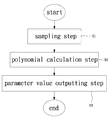
- FIG. 1 shows a flowchart of a method for determining the parameter values of an induction machine by means of polynomial calculations according to an embodiment of the invention.
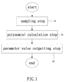
- FIG. 2 shows a diagram of an equivalent circuit of the induction machine under the steady state according to the embodiment of the invention.
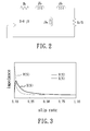
- FIG. 3 shows a relation curve of an impedance of the induction machine during which the induction machine transfers from a stationary state to a synchronous rotational speed state.
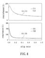
- FIG. 4 shows a simulated impedance relation curve and an actual impedance relation curve under the same sampling slip rate.
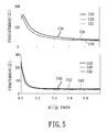
- FIG. 5 shows the relation curves of the resistance and the reactance.
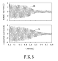
- FIG. 6 shows a simulated current relation curve of the induction machine using the parameter values obtained from the method of the invention, as well as an actual current relation curve of the induction machine.
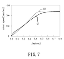
- FIG. 7 shows a simulated relation curve of a rotational speed of the induction machine using the parameter values obtained from the method of the invention, as well as an actual relation curve of the rotational speed of the induction machine.
- slip rate is a ratio of a rotational speed difference to a synchronous rotational speed of a rotating magnetic field of an induction machine, in which the rotational speed difference is the difference between an actual rotational speed and the synchronous rotational speed of the induction machine, as it can be readily appreciated by the persons having ordinary skill in the art.
- FIG. 1 shows a flowchart of a method for determining parameters of an induction machine by means of polynomial calculations according to an embodiment of the invention.
- the method can be performed by a computer system to execute a program for determining the mechanical parameters of an induction machine, such as the moment of inertia and the friction coefficient of a three-phase inductive electric motor.
- the computer system is dedicated for simulating the induction machine. As such, the accuracy of the computer system in simulating the induction machine can be improved, and the initial value is not required.
- the method of the embodiment of the invention is able to determine the optimal solution via one-off calculation procedure, thereby reducing the calculation complexity.
- the performance of the dedicated computer system can be improved.
- a measuring instrument can be used to measure the time-varying voltage, current and rotational speed of the induction machine during which the induction machine transfers from the initial state to the steady state.
- the time-varying voltage, current and rotational speed may have the same sampling scale, and the time-varying voltage and current can be analyzed under time domain to obtain the amplitude and phase at each sampling scale. Accordingly, the equivalent resistance and reactance of the primary side of the induction machine at every sampling point can be obtained.
- the slip rate at each sampling point can be determined from the rotational speeds at the individual sampling points.
- the method of the embodiment of the invention may include a sampling step S 1 , a polynomial calculation step S 2 and a parameter value outputting step S 3 .
- the sampling step S 1 is configured to sample a voltage signal, a current signal and a rotational speed signal of the induction machine at the time the induction machine is started, and to calculate the resistance and the reactance of the induction machine under different slip rates based on the sampled voltage and current signals, as elaborated below.
- the transient time constant of the induction machine is small, the transient value caused by the inductor will rapidly reduce to an ignorable range in the early stage of the start.
- the voltage and current characteristics are determined primarily by the steady state impedance.
- FIG. 2 shows a diagram of an equivalent circuit of the induction machine under the steady state according to the embodiment of the invention.
- the equivalent circuit may include a stator resistance Rs, a stator reactance Xs and a magnetizing reactance Xm, which are connected in series to form an open loop.
- the equivalent circuit further includes a rotor reactance Xr and a per slip rotor resistance Rr/S, which are connected to the magnetizing reactance Xm to form a closed loop.
- the symbol “S” refers to the slip rate.
- R + j ⁇ ⁇ X R S + j ⁇ ⁇ X s + j ⁇ ⁇ X m ⁇ ( R r / S + j ⁇ ⁇ X r ) j ⁇ ⁇ X m + ( R r / S + j ⁇ ⁇ X r ) . ( 1 )
- R is the resistance of the primary side of the induction machine
- X is the reactance of the primary side of the induction machine
- Rs is the stator resistance
- Xs is the stator reactance
- Xm is the magnetizing reactance
- Xr is the rotor reactance
- Rr/S is the per slip rotor resistance.
- both the resistance and the reactance can be represented as a function of the slip rate “S,” as expressed in formulas (2) and (3) below:
- R ⁇ ( S ) R S + X m 2 ⁇ R r / S ( R r / S ) 2 + ( X m + X r ) 2 .
- X ⁇ ( S ) X S + X m - X m 2 ⁇ ( X m + X r ) ( R r / S ) 2 + ( X m + X r ) 2 . ( 3 )
- the polynomial calculation step S 2 may calculate a coefficient for a polynomial fraction. The detail is described below, but it is not taken as a limited sense.
- R R S + SX m 2 ⁇ R r + S 2 ⁇ R S ⁇ ( X m + X r ) 2 / R r 2 1 + S 2 ⁇ ( X m + X r ) 2 / R r 2 .
- the error between the predicted value and the experimental value may be expressed as a polynomial fraction, as shown in a formula (9) below:
- the difference between the predicted value and the actual value may be calculated, and the sum of the squared absolute value of the difference may be calculated to generate a target function “E,” as shown in a formula (11) below:
- the partial derivatives of the target function “E” may be determined and each partial derivative is set as zero, as expressed in formulas (12), (13), (14), (15), (16) and (17) below:
- the parameter value outputting step S 3 is configured to calculate the parameter values of an equivalent circuit based on the coefficients of the polynomial fraction, to calculate a moment of inertia and a friction coefficient of the induction machine based on the calculated parameter values of the equivalent circuit and the rotational speed signal, and to output the calculated moment of inertia and the friction coefficient.
- the detail is described below, but it is not taken as a limited sense.
- the above formula (7) includes five independent variables (Rs, Xs, Xm, Xr and Rr). However, this does not mean that every parameter of the equivalent circuit of the three-phase induction machine can be determined independently.
- the resistance of the equivalent circuit of the induction machine may be calculated according to the formula (2).
- the reactance of the equivalent circuit of the induction machine may be calculated according to the formula (3).
- the reactance may consist of a constant reactance and a varying reactance that varies with the slip rate.
- the stator reactance and the magnetizing reactance may be combined as the constant reactance.
- the magnetizing reactance Xm, the rotor reactance Xr and the stator reactance Xs may have a relation as expressed in a formula (26) below:
- the predetermined ratio ⁇ may be between 0.95 and 1.05, and the formula (26) may be introduced into formula (7) to obtain a formula (27):
- stator reactance Xs, the rotor reactance Xr and the rotor resistance Rr may be expressed as formulas (29), (30) and (31), respectively:
- X S ⁇ 3 ⁇ X m (29).
- R r X m 2 / ⁇ 1 (31).
- stator resistance Rs The value of the stator resistance Rs may be calculated via an optimized ratio, as expressed below:
- stator resistance Rs may be expressed in a formula (34) below:
- the dynamic model of the three-phase induction machine may be expressed as formulas (35), (36), (37) and (38) below:
- v qs ( R S +L S p ) i qs +L m pi qr (35).
- v ds ( R S +L S p ) i ds +L m pi dr (36).
- v qr L m pi qs ⁇ r L m i ds +( R r +L r p ) i qr ⁇ r L r i dr (37).
- v dr ⁇ r L m i qs +L m pi ds + ⁇ r L r i qr +( R r +L r p ) i dr (38).
- i qs and i ds are the currents of the stator
- i qr and i dr are the currents of the rotor
- v qs and v ds are the voltages of the stator
- v qr and v dr are the voltages of the rotor
- “p” is the differential factor.
- the moment of inertia “J” and the friction coefficient “B” determine the relationship between the output rotational torque and the rotational speed of the induction machine, the moment of inertia and the friction coefficient can be obtained when the output rotational torque and the rotational speed are known.
- Equation (40) “J” is the moment of inertia and “B” is the friction coefficient. ⁇ dot over ( ⁇ ) ⁇ and ⁇ are the angular acceleration and the angular velocity, respectively. “T” is the rotational torque.
- n is the serial number of the discrete data.
- ⁇ (n) and ⁇ (n ⁇ 1) are the angular velocities at different discrete time frames.
- T(n) is a discrete rotational torque.
- a target function may be set to obtain the optimal parameter values, as expressed in a formula (42) below.
- the optimal values of the moment of inertia “J” and the friction coefficient “B” are obtained. Namely, the gradients of the moment of inertia “J” and the friction coefficient “B” in the formula (42) are set as zero, then “J” and “B” may be obtained from a formula (43) below:
- ⁇ r (n) and ⁇ r (n ⁇ 1) are the angular velocity at different discrete time frames.
- a three-phase induction machine (e.g. 4 poles, 0.5 hp, and 60 Hz) may be exemplarily used.
- the stator resistance Rs is 38 ⁇
- the rotor resistance Rr is 12 ⁇
- the magnetizing reactance Xm is 288 ⁇
- the stator reactance Xs is 17 ⁇
- the rotor reactance Xr is 17 ⁇ .
- the coefficients of the polynomial fraction and the parameter values of the induction machine may be obtained from the above formulas.
- the method of the embodiment of the invention simply requires one-off calculation procedure to determine the optimal values of the parameters of the induction machine.
- the predetermined ratio ⁇ is dependent on the values of the Xm, Xs and Xr, in which the values of the Xm, Xs and Xr depend from each other.
- the simulated impedance relation curve should be consistent with the actual impedance relation curve irrespective of whether the change of the predetermined ratio ⁇ is small or large.
- a simulation software such as SPICE may be used to draw the relation curves of the resistance and the reactance. It can be recognized from FIG.
- the coefficients of the polynomial fraction are obtained as Table 2 above.
- the relation curves of the resistance and the reactance are shown in FIG. 5 . From FIG. 5 , it can be recognized that the simulated resistance relation curve C 31 using the determined coefficients of the polynomial fraction has a high level of consistence with the actual resistance relation curve C 32 of the polynomial fraction, and that the simulated reactance relation curve C 41 using the determined coefficients of the polynomial fraction has a high level of consistence with the actual reactance relation curve C 42 of the polynomial fraction.
- the predetermined ratio ⁇ is set as 1, the values of the parameters of the induction machine are obtained as Table 2. In FIG.
- the parameter values in Table 2 are used to simulate the dynamic behavior of the system, and the simulated result may be compared with the actual result.
- a simulated current relation curve C 6 is generated using the values in Table 2, and is compared with the actual current relation curve C 5 . It can be observed that the actual current relation curve C 5 is very close to the simulated current relation curve C 6 . Thus, the current patterns in FIG. 6 will appear to be in a steady state. Therefore, it is proven that the change of current is primarily affected by the steady state term.
- a standard test may be performed to determine the values of the parameters, and the determined parameter values may also be used to simulate the dynamic behavior of the system.
- the generated result is less accurate than that generated by the method of the embodiment of the invention.
- the data of two operational conditions are used as reference for determining the values of the parameters.
- the determined parameter values will inevitably have some errors caused thereby.
- the error must be reduced to a minimum extent.
- the method of the embodiment of the invention may be used to reduce the error to a minimum extent via the polynomial calculations.
- FIG. 7 shows a simulated relation curve of a rotational speed of the induction machine using the parameter values obtained from the method of the embodiment of the invention, as well as an actual relation curve of the rotational speed of the induction machine.
- the rotational moment of inertia “J” of the induction machine is 0.38 (g ⁇ m 2 ), and that the friction coefficient “B” of said machine is 0.61 (mN ⁇ m/(rad/sec)).
- the target function “Er” in formula (42) is 8.388 (rad/sec), which is very small.
- the actual relation curve of the rotational speed C 7 is close to the simulated relation curve of the rotational speed C 8 . Therefore, it is proven that the method of the embodiment of the invention is able to determine the parameter values approximate to the actual values.
- the determined parameter values will have high accuracy.
- the method of the embodiment of the invention is able to calculate the resistance and the reactance of the induction machine under different slip rates based on the time-varying voltage, current and rotational speed signals of the induction machine generated at the time the induction machine is started.
- the method also calculates the coefficients of the polynomial fraction based on the resistance and the reactance, calculates the parameter values of the equivalent circuit based on the coefficients of the polynomial fraction, calculates the moment of inertia and the friction coefficient based on the calculated parameter values of the equivalent circuit and the rotational speed signal, and finally outputs the values of the moment of inertia and the friction coefficient.
- the values of the moment of inertia and the friction coefficient may be outputted to a display, a database, a storage device, a computer or the like.
- the method of the embodiment of the invention does not need to determine the parameter values in a no-load low-voltage manner and does not require the initial value.
- the method of the embodiment of the invention is able to obtain the optimal values via one-off calculation procedure.
- the calculation complexity can be reduced, and the calculated parameter values will have high reliability and accuracy.
- the disadvantages of the conventional method such as the use of an initial value, the need to perform the method in a no-load low-voltage manner, as well as high calculation complexity, can be overcome. Accordingly, the user is able to predict the parameter values and the operational condition of the induction machine, improving the reliability and accuracy of the precision control technology.
Abstract
Description
wherein,
α2=(X m +X r)2 /R r 2
β0 =R S
β1 =X m 2 /R r
β2 =R S(X m +X r)2 /R r 2
β3 =X m +X S
β4=[(X m +X r)2(X m +X S)−X m 2(X m +X r)
wherein “R” is the resistance of a primary side of the induction machine, “X” is the reactance of the primary side of the induction machine, “S” is the slip rates, “Xm” is the magnetizing reactance, “Xr” is the rotor reactance, “Xs” is a stator reactance, “Rr” is the rotor resistance, and “Rs” is the stator resistance.
X S=β3 −X m.
X r=η(X m +X S)−X m=ηβ3 −X m.
R r =X m 2/β1.
wherein ω(n) and ω(n−1) are angular velocities at different discrete time frames, wherein T(n) is a discrete rotational torque, and wherein “n” is a serial number of discrete data and is 0, 1, 2 . . . and so on.
(R i ,X i ,S i),i=1, . . . ,n (8).
E i′=[Ri(1+α2Si 2)−(β0+β1Si+β2Si 2)]+j[Xi(1+α2Si 2)−(β3+β4S2)],i=1, . . . ,N (10).
B=A −1 C (25).
X S=β3 −X m (29).
X r=η(X m +X S)−X m=ηβ3 −X m (30).
R r =X m 2/β1 (31).
v qs=(R S +L S p)i qs +L m pi qr (35).
v ds=(R S +L S p)i ds +L m pi dr (36).
v qr =L m pi qs−ωr L m i ds+(R r +L r p)i qr−ωr L r i dr (37).
v dr=ωr L m i qs +L m pi ds+ωr L r i qr+(R r +L r p)i dr (38).
T=3PL m(i dr i qs −i qr i ds) (39).
J{dot over (ω)}+Bω=T (40).
J(ω(n)−ω(n−1))+Bω(n)=T(n),n=0,1, . . . (41).
| TABLE 1 |
| The Coefficients of the Polynomial Fraction and |
| the Parameter Values of the Induction Machine |
| The Coefficients | ||
| of the Polynomial | The Parameters of the Induction Machine |
| Fraction | η = 0.95 | η = 1.00 | η = 1.05 |
| α2 = 64.6 | Xm = 280.7 | Xm = 280.0 | Xm = 295.1 |
| β0 = 38.0 | XS = 24.3 | XS = 17.0 | XS = 9.88 |
| B1 = 6912.0 | Xr = 9.0 | Xr = 17.0 | Xr = 25.1 |
| B2 = 24548.2 | RS = 38.0 | RS = 38.0 | RS = 38.0 |
| B3 = 305.0 | Rr = 11.4 | Rr = 12.0 | Rr = 12.6 |
| B4 = 21352.1 | |||
| TABLE 2 |
| The Coefficients of a Polynomial Fraction and the |
| Parameter Values of the Induction Machine |
| The Coefficients of the | The Parameter Values of the | ||
| Polynomial Fraction | Induction Machine (Ω) | ||
| α2 = 850.0 | Xm = 291.0 | ||
| β0 = 38.8 | XS = 17.2 | ||
| B1 = 6968.3 | Xr = 17.2 | ||
| B2 = 21652.4 | RS = 26.0 | ||
| B3 = 308.2 | Rr = 12.1 | ||
| B4 = 28468.6 | |||
Claims (9)
α2=(X m +X r)2 /R r 2
β0 =R S
β1 =X m 2 /R r
β2 =R S(X m +X r)2 /R r 2
β3 =X m +X S
β4=[(X m +X r)2(X m +X S)−X m 2(X m +X r)
X S=β3 −X m.
X r=η(X m +X S)−X m=ηβ3 −X m.
R r =X m 2/β1.
Applications Claiming Priority (3)
| Application Number | Priority Date | Filing Date | Title |
|---|---|---|---|
| TW104130288 | 2015-09-14 | ||
| TW104130288A | 2015-09-14 | ||
| TW104130288A TW201710924A (en) | 2015-09-14 | 2015-09-14 | Method for estimating parameters of the induction machine by the polynomial regression |
Publications (2)
| Publication Number | Publication Date |
|---|---|
| US20170075861A1 US20170075861A1 (en) | 2017-03-16 |
| US9740664B2 true US9740664B2 (en) | 2017-08-22 |
Family
ID=58236901
Family Applications (1)
| Application Number | Title | Priority Date | Filing Date |
|---|---|---|---|
| US14/956,334 Active US9740664B2 (en) | 2015-09-14 | 2015-12-01 | Method for determining parameter values of an induction machine by means of polynominal calculations |
Country Status (2)
| Country | Link |
|---|---|
| US (1) | US9740664B2 (en) |
| TW (1) | TW201710924A (en) |
Cited By (1)
| Publication number | Priority date | Publication date | Assignee | Title |
|---|---|---|---|---|
| US10391884B2 (en) * | 2015-03-27 | 2019-08-27 | Calsonic Kansei Corporation | Drive power control device for electric vehicle |
Families Citing this family (4)
| Publication number | Priority date | Publication date | Assignee | Title |
|---|---|---|---|---|
| CN113779911A (en) * | 2020-06-10 | 2021-12-10 | 英业达科技有限公司 | Format conversion method and device |
| CN113688474B (en) * | 2021-08-13 | 2024-02-09 | 北京航天飞腾装备技术有限责任公司 | Electric steering engine simulation modeling method based on parameter identification |
| CN114156881B (en) * | 2021-12-08 | 2023-06-23 | 国网宁夏电力有限公司电力科学研究院 | Method for generating transient process sample of power system based on time sequence item-containing proxy model |
| CN114386286B (en) * | 2022-01-18 | 2023-08-08 | 上海交通大学 | Main insulation heat conductivity coefficient calculation method and system based on high heat conductivity mica tape manufacturing |
Citations (46)
| Publication number | Priority date | Publication date | Assignee | Title |
|---|---|---|---|---|
| US3679924A (en) * | 1971-01-19 | 1972-07-25 | Canadian Patents Dev | Synchronous reluctance motors and method of starting |
| US4207510A (en) * | 1978-01-16 | 1980-06-10 | Sri International | Control method and means for efficient operation of brushless d-c motors over a wide range of operating conditions |
| US4947332A (en) * | 1989-09-27 | 1990-08-07 | General Motors Corporation | Road surface estimation |
| US5388052A (en) * | 1993-03-31 | 1995-02-07 | Otis Elevator Company | Method of operating an induction motor |
| US5619435A (en) * | 1993-04-07 | 1997-04-08 | Ford Motor Company | Method and apparatus for simulating the behavior and operation of a three-phase induction machine |
| US5671143A (en) * | 1994-11-25 | 1997-09-23 | Itt Automotive Europe Gmbh | Driving stability controller with coefficient of friction dependent limitation of the reference yaw rate |
| US5671982A (en) * | 1994-11-25 | 1997-09-30 | Itt Automotive Europe Gmbh | System for applying a yawing control moment by setting brake valve opening and closing times |
| US5694321A (en) * | 1994-11-25 | 1997-12-02 | Itt Automotive Europe Gmbh | System for integrated driving stability control |
| US5710705A (en) * | 1994-11-25 | 1998-01-20 | Itt Automotive Europe Gmbh | Method for determining an additional yawing moment based on side slip angle velocity |
| US5711024A (en) * | 1994-11-25 | 1998-01-20 | Itt Automotive Europe Gmbh | System for controlling yaw moment based on an estimated coefficient of friction |
| US5710704A (en) * | 1994-11-25 | 1998-01-20 | Itt Automotive Europe Gmbh | System for driving stability control during travel through a curve |
| US5732377A (en) * | 1994-11-25 | 1998-03-24 | Itt Automotive Europe Gmbh | Process for controlling driving stability with a yaw rate sensor equipped with two lateral acceleration meters |
| US5742507A (en) * | 1994-11-25 | 1998-04-21 | Itt Automotive Europe Gmbh | Driving stability control circuit with speed-dependent change of the vehicle model |
| US5762406A (en) * | 1995-11-17 | 1998-06-09 | Aisin Seiki Kabushiki Kaisha | Vehicle motion control system involving priority oversteer and understeer restraining control |
| US5774821A (en) * | 1994-11-25 | 1998-06-30 | Itt Automotive Europe Gmbh | System for driving stability control |
| US5857754A (en) * | 1996-02-02 | 1999-01-12 | Aisin Seiki Kabushiki Kaisha | Vehicle motion control system |
| US5869943A (en) * | 1996-10-23 | 1999-02-09 | Aisin Seiki Kabushiki Kaisha | Vehicle motion control system |
| US5913578A (en) * | 1996-10-30 | 1999-06-22 | Aisin Seiki Kabushiki Kaisha | Vehicle motion control system |
| US5927830A (en) * | 1995-11-30 | 1999-07-27 | Aisin Seiki Kabushiki Kaisha | Vehicle motion control system for immediately terminating braking control when the vehicle enters onto a stepped or rough road |
| US5964819A (en) * | 1995-06-22 | 1999-10-12 | Nissan Motor Co., Ltd. | Vehicle yawing behavior control apparatus |
| US20020011093A1 (en) * | 2000-06-29 | 2002-01-31 | Fuji Jukogyo Kabushiki Kaisha | Road friction coefficient estimating apparatus and vehicle equipped with road friction coefficient estimating apparatus |
| US20020111752A1 (en) * | 2000-11-20 | 2002-08-15 | Toyota Jidosha Kabushiki Kaisha | Apparatus and method for estimating maximum road friction coefficient |
| US6456920B1 (en) * | 1999-11-29 | 2002-09-24 | Aisin Seiki Kabushiki Kaisha | Apparatus for estimating a vehicle side slip angle |
| US20020149341A1 (en) * | 2001-02-13 | 2002-10-17 | Jinghan Tao | Method and system for measuring a parameter of motor operation |
| US6549842B1 (en) * | 2001-10-31 | 2003-04-15 | Delphi Technologies, Inc. | Method and apparatus for determining an individual wheel surface coefficient of adhesion |
| US20040019439A1 (en) * | 2002-07-23 | 2004-01-29 | Yehia El-Ibiary | Induction motor module and motor incorporating same |
| US20050071095A1 (en) * | 2003-09-30 | 2005-03-31 | Yehia El-Ibiary | Motor parameter estimation method and apparatus |
| US20050067991A1 (en) * | 2003-09-30 | 2005-03-31 | Yehia El-Ibiary | System and method for identifying operational parameters of a motor |
| US20050125135A1 (en) * | 2002-05-23 | 2005-06-09 | Mitsubishi Denki Kabushiki Kaisha | Motor vehicle state detecting system |
| US20050125131A1 (en) * | 2003-10-02 | 2005-06-09 | Toyoda Koki Kabushiki Kaisha | Integrated control apparatus for vehicle |
| US20060015236A1 (en) * | 2004-07-13 | 2006-01-19 | Nissan Motor Co., Ltd. | Drive force distribution system for four wheel independent drive vehicle |
| US20080133066A1 (en) * | 2004-08-06 | 2008-06-05 | Honda Motor Co., Ltd. | Control Device for Vehicle |
| US20080262692A1 (en) * | 2007-04-18 | 2008-10-23 | Masaru Kogure | Road-surface friction-coefficient estimating device |
| US20090210128A1 (en) * | 2006-09-07 | 2009-08-20 | Yokohama National University | Slip ratio estimating device and slip ratio control device |
| US20100090629A1 (en) * | 2008-10-15 | 2010-04-15 | Tesla Motors, Inc. | Flux controlled motor management |
| US20100114447A1 (en) * | 2007-01-18 | 2010-05-06 | Hitach, Ltd. | Automobile and control device for automobile |
| US20100114449A1 (en) * | 2007-04-17 | 2010-05-06 | Nissan Motor Co. Ltd | Device and method for estimating frictional condition of ground contact surface of wheel |
| US20100194324A1 (en) * | 2009-02-03 | 2010-08-05 | General Electric Company | Stator turn fault detection apparatus and method for induction machine |
| US20110209521A1 (en) * | 2008-10-29 | 2011-09-01 | Nissan Motor Co., Ltd. | Device and method for estimating frictional condition of ground surface with which vehicle is in contact |
| US20110276301A1 (en) * | 2010-05-06 | 2011-11-10 | I Shou University | System for computing machine parameters of an induction machine |
| US20120016646A1 (en) * | 2009-03-30 | 2012-01-19 | Honda Motor Co., Ltd. | Device for estimating state quantity of skid motion of vehicle |
| US20120029783A1 (en) * | 2009-03-30 | 2012-02-02 | Honda Motor Co., Ltd. | Road surface friction coefficient estimating device |
| US20120270325A1 (en) * | 2011-04-19 | 2012-10-25 | Ronald Kent Sperry | System and method for evaluating the performance of a pump |
| US20120279793A1 (en) * | 2010-01-22 | 2012-11-08 | Akira Kikuchi | Electrically driven vehicle |
| US8519651B2 (en) * | 2010-10-11 | 2013-08-27 | Mabe, S.A. De C.V. | Dephasing control |
| US20150298577A1 (en) * | 2012-04-20 | 2015-10-22 | Hitachi Construction Machinery Co., Ltd. | Electric drive vehicle |
-
2015
- 2015-09-14 TW TW104130288A patent/TW201710924A/en unknown
- 2015-12-01 US US14/956,334 patent/US9740664B2/en active Active
Patent Citations (64)
| Publication number | Priority date | Publication date | Assignee | Title |
|---|---|---|---|---|
| US3679924A (en) * | 1971-01-19 | 1972-07-25 | Canadian Patents Dev | Synchronous reluctance motors and method of starting |
| US4207510A (en) * | 1978-01-16 | 1980-06-10 | Sri International | Control method and means for efficient operation of brushless d-c motors over a wide range of operating conditions |
| US4947332A (en) * | 1989-09-27 | 1990-08-07 | General Motors Corporation | Road surface estimation |
| US5388052A (en) * | 1993-03-31 | 1995-02-07 | Otis Elevator Company | Method of operating an induction motor |
| US5619435A (en) * | 1993-04-07 | 1997-04-08 | Ford Motor Company | Method and apparatus for simulating the behavior and operation of a three-phase induction machine |
| US5774821A (en) * | 1994-11-25 | 1998-06-30 | Itt Automotive Europe Gmbh | System for driving stability control |
| US5862503A (en) * | 1994-11-25 | 1999-01-19 | Itt Automotive Europe Gmbh | System for driving stability control |
| US5694321A (en) * | 1994-11-25 | 1997-12-02 | Itt Automotive Europe Gmbh | System for integrated driving stability control |
| US5711025A (en) * | 1994-11-25 | 1998-01-20 | Itt Automotive Europe Gmbh | Driving stability control system with selective brake actuation |
| US5710705A (en) * | 1994-11-25 | 1998-01-20 | Itt Automotive Europe Gmbh | Method for determining an additional yawing moment based on side slip angle velocity |
| US5711024A (en) * | 1994-11-25 | 1998-01-20 | Itt Automotive Europe Gmbh | System for controlling yaw moment based on an estimated coefficient of friction |
| US5711023A (en) * | 1994-11-25 | 1998-01-20 | Itt Automotive Europe Gmbh | System for determining side slip angle |
| US5710704A (en) * | 1994-11-25 | 1998-01-20 | Itt Automotive Europe Gmbh | System for driving stability control during travel through a curve |
| US5732377A (en) * | 1994-11-25 | 1998-03-24 | Itt Automotive Europe Gmbh | Process for controlling driving stability with a yaw rate sensor equipped with two lateral acceleration meters |
| US5742507A (en) * | 1994-11-25 | 1998-04-21 | Itt Automotive Europe Gmbh | Driving stability control circuit with speed-dependent change of the vehicle model |
| US5671143A (en) * | 1994-11-25 | 1997-09-23 | Itt Automotive Europe Gmbh | Driving stability controller with coefficient of friction dependent limitation of the reference yaw rate |
| US5671982A (en) * | 1994-11-25 | 1997-09-30 | Itt Automotive Europe Gmbh | System for applying a yawing control moment by setting brake valve opening and closing times |
| US5964819A (en) * | 1995-06-22 | 1999-10-12 | Nissan Motor Co., Ltd. | Vehicle yawing behavior control apparatus |
| US5762406A (en) * | 1995-11-17 | 1998-06-09 | Aisin Seiki Kabushiki Kaisha | Vehicle motion control system involving priority oversteer and understeer restraining control |
| US5927830A (en) * | 1995-11-30 | 1999-07-27 | Aisin Seiki Kabushiki Kaisha | Vehicle motion control system for immediately terminating braking control when the vehicle enters onto a stepped or rough road |
| US5857754A (en) * | 1996-02-02 | 1999-01-12 | Aisin Seiki Kabushiki Kaisha | Vehicle motion control system |
| US5869943A (en) * | 1996-10-23 | 1999-02-09 | Aisin Seiki Kabushiki Kaisha | Vehicle motion control system |
| US5913578A (en) * | 1996-10-30 | 1999-06-22 | Aisin Seiki Kabushiki Kaisha | Vehicle motion control system |
| US6456920B1 (en) * | 1999-11-29 | 2002-09-24 | Aisin Seiki Kabushiki Kaisha | Apparatus for estimating a vehicle side slip angle |
| US20020011093A1 (en) * | 2000-06-29 | 2002-01-31 | Fuji Jukogyo Kabushiki Kaisha | Road friction coefficient estimating apparatus and vehicle equipped with road friction coefficient estimating apparatus |
| US6556911B2 (en) * | 2000-06-29 | 2003-04-29 | Fuji Jukogyo Kabushiki Kaisha | Road friction coefficient estimating apparatus and vehicle equipped with road friction coefficient estimating apparatus |
| US20020111752A1 (en) * | 2000-11-20 | 2002-08-15 | Toyota Jidosha Kabushiki Kaisha | Apparatus and method for estimating maximum road friction coefficient |
| US6473682B2 (en) * | 2000-11-20 | 2002-10-29 | Toyota Jidosha Kabushiki Kaisha | Apparatus and method for estimating maximum road friction coefficient |
| US20020149341A1 (en) * | 2001-02-13 | 2002-10-17 | Jinghan Tao | Method and system for measuring a parameter of motor operation |
| US6549842B1 (en) * | 2001-10-31 | 2003-04-15 | Delphi Technologies, Inc. | Method and apparatus for determining an individual wheel surface coefficient of adhesion |
| US20050125135A1 (en) * | 2002-05-23 | 2005-06-09 | Mitsubishi Denki Kabushiki Kaisha | Motor vehicle state detecting system |
| US20040019439A1 (en) * | 2002-07-23 | 2004-01-29 | Yehia El-Ibiary | Induction motor module and motor incorporating same |
| US6862538B2 (en) * | 2002-07-23 | 2005-03-01 | Reliance Electric Technologies, Llc. | Induction motor module and motor incorporating same |
| US20050071095A1 (en) * | 2003-09-30 | 2005-03-31 | Yehia El-Ibiary | Motor parameter estimation method and apparatus |
| US20070118307A1 (en) * | 2003-09-30 | 2007-05-24 | Yehia El-Ibiary | Motor parameter estimation method and apparatus |
| US20050067991A1 (en) * | 2003-09-30 | 2005-03-31 | Yehia El-Ibiary | System and method for identifying operational parameters of a motor |
| US20070118308A1 (en) * | 2003-09-30 | 2007-05-24 | Yehia El-Ibiary | Motor parameter estimation method and apparatus |
| US7135830B2 (en) * | 2003-09-30 | 2006-11-14 | Reliance Electric Technologies, Llc | System and method for identifying operational parameters of a motor |
| US7184902B2 (en) * | 2003-09-30 | 2007-02-27 | Reliance Electric Technologies, Llc | Motor parameter estimation method and apparatus |
| US7171296B2 (en) * | 2003-10-02 | 2007-01-30 | Toyoda Koki Kabushiki Kaisha | Integrated control apparatus for vehicle |
| US20050125131A1 (en) * | 2003-10-02 | 2005-06-09 | Toyoda Koki Kabushiki Kaisha | Integrated control apparatus for vehicle |
| US20060015236A1 (en) * | 2004-07-13 | 2006-01-19 | Nissan Motor Co., Ltd. | Drive force distribution system for four wheel independent drive vehicle |
| US7440834B2 (en) * | 2004-07-13 | 2008-10-21 | Nissan Motor Co., Ltd. | Drive force distribution system for four wheel independent drive vehicle |
| US20080133066A1 (en) * | 2004-08-06 | 2008-06-05 | Honda Motor Co., Ltd. | Control Device for Vehicle |
| US8170768B2 (en) * | 2006-09-07 | 2012-05-01 | Yokohama National University | Slip ratio estimating device and slip ratio control device |
| US20090210128A1 (en) * | 2006-09-07 | 2009-08-20 | Yokohama National University | Slip ratio estimating device and slip ratio control device |
| US20100114447A1 (en) * | 2007-01-18 | 2010-05-06 | Hitach, Ltd. | Automobile and control device for automobile |
| US20100114449A1 (en) * | 2007-04-17 | 2010-05-06 | Nissan Motor Co. Ltd | Device and method for estimating frictional condition of ground contact surface of wheel |
| US8483926B2 (en) * | 2007-04-17 | 2013-07-09 | Nissan Motor Co., Ltd. | Device and method for estimating frictional condition of ground contact surface of wheel |
| US20080262692A1 (en) * | 2007-04-18 | 2008-10-23 | Masaru Kogure | Road-surface friction-coefficient estimating device |
| US8244432B2 (en) * | 2007-04-18 | 2012-08-14 | Fuji Jukogyo Kabushiki Kaisha | Road-surface friction-coefficient estimating device |
| US20100090629A1 (en) * | 2008-10-15 | 2010-04-15 | Tesla Motors, Inc. | Flux controlled motor management |
| US7960928B2 (en) * | 2008-10-15 | 2011-06-14 | Tesla Motors, Inc. | Flux controlled motor management |
| US20110209521A1 (en) * | 2008-10-29 | 2011-09-01 | Nissan Motor Co., Ltd. | Device and method for estimating frictional condition of ground surface with which vehicle is in contact |
| US20100194324A1 (en) * | 2009-02-03 | 2010-08-05 | General Electric Company | Stator turn fault detection apparatus and method for induction machine |
| US8140291B2 (en) * | 2009-02-03 | 2012-03-20 | General Electric Company | Stator turn fault detection apparatus and method for induction machine |
| US20120016646A1 (en) * | 2009-03-30 | 2012-01-19 | Honda Motor Co., Ltd. | Device for estimating state quantity of skid motion of vehicle |
| US20120029783A1 (en) * | 2009-03-30 | 2012-02-02 | Honda Motor Co., Ltd. | Road surface friction coefficient estimating device |
| US20120279793A1 (en) * | 2010-01-22 | 2012-11-08 | Akira Kikuchi | Electrically driven vehicle |
| US20110276301A1 (en) * | 2010-05-06 | 2011-11-10 | I Shou University | System for computing machine parameters of an induction machine |
| US8676524B2 (en) * | 2010-05-06 | 2014-03-18 | I-Shou University | System for computing machine parameters of an induction machine |
| US8519651B2 (en) * | 2010-10-11 | 2013-08-27 | Mabe, S.A. De C.V. | Dephasing control |
| US20120270325A1 (en) * | 2011-04-19 | 2012-10-25 | Ronald Kent Sperry | System and method for evaluating the performance of a pump |
| US20150298577A1 (en) * | 2012-04-20 | 2015-10-22 | Hitachi Construction Machinery Co., Ltd. | Electric drive vehicle |
Non-Patent Citations (2)
| Title |
|---|
| English abstract translation of "Method for determining complete parameter values of an induction machine by parameter of time varying". |
| Rong-Ching Wu, "Method for determining complete parameter values of an induction machine by parameter of time varying", Search & Discovery Research at ISU & EDH. Summer 2012, pp. 14-20, vol. 14, I-Shou University, Taiwan. |
Cited By (1)
| Publication number | Priority date | Publication date | Assignee | Title |
|---|---|---|---|---|
| US10391884B2 (en) * | 2015-03-27 | 2019-08-27 | Calsonic Kansei Corporation | Drive power control device for electric vehicle |
Also Published As
| Publication number | Publication date |
|---|---|
| US20170075861A1 (en) | 2017-03-16 |
| TW201710924A (en) | 2017-03-16 |
Similar Documents
| Publication | Publication Date | Title |
|---|---|---|
| US9740664B2 (en) | Method for determining parameter values of an induction machine by means of polynominal calculations | |
| JP4253903B2 (en) | Induction motor drive and its parameter evaluation method | |
| JP4685509B2 (en) | AC motor drive control device and drive control method | |
| US20140167674A1 (en) | System for determining a magnetizing curve and rotor resistance of an induction machine and method of making same | |
| CN111656674B (en) | Control device, control method, and motor drive system for power conversion device | |
| CN111656676B (en) | Control device for power conversion device and motor drive system | |
| JP2012519464A (en) | Method and apparatus for determining the position of a rotor shaft of a permanent magnet excited synchronous machine without an angle sensor based on current and voltage signals | |
| CN106655958A (en) | Permanent magnet motor torque compensation method and device | |
| US11757390B2 (en) | Motor inductance measurement device, motor drive system, and motor inductance measurement method | |
| Aarniovuori et al. | Induction motor torque estimation accuracy using motor terminal variables | |
| Diab | Implementation of a novel full-order observer for speed sensorless vector control of induction motor drives | |
| US20150177328A1 (en) | Automated motor adaptation | |
| Aree | Analytical determination of speed-torque and speed-current curves of single-cage induction motor under supply voltage and frequency variations | |
| US8676524B2 (en) | System for computing machine parameters of an induction machine | |
| Rehman | Elimination of the stator resistance sensitivity and voltage sensor requirement problems for DFO control of an induction Machine | |
| Karlovský et al. | Sensorless determination of induction motor drive speed using MRAS method | |
| Kanmachi et al. | Sensor-less speed control of an induction motor | |
| Yong et al. | Optimization-based position estimation of PM synchronous motor drives with magnetic saturation | |
| US20200358385A1 (en) | Method for determining motor parameters during commissioning of synchronous and asynchronous electric motors and related commissioned electric motor | |
| KR101590251B1 (en) | Estimation method of rotor time constant with motor at standstill | |
| Dabbeti et al. | Sensorless speed control of an induction motor drive using predictive current and torque controllers | |
| Gayathri et al. | Performance of vector controlled induction motor drive with reactive power based MRAS rotor resistance estimator | |
| Zamora et al. | Rotor-speed estimator for induction motors using voltage and current measurements | |
| Amalkar et al. | Design and implementation of sensorless speed control for induction motor drive using an optimized extended kalman filter | |
| Abu-Rub et al. | Simple observer for induction motor speed sensorless control |
Legal Events
| Date | Code | Title | Description |
|---|---|---|---|
| AS | Assignment |
Owner name: I-SHOU UNIVERSITY, TAIWAN Free format text: ASSIGNMENT OF ASSIGNORS INTEREST;ASSIGNOR:WU, RONG-CHING;REEL/FRAME:037183/0550 Effective date: 20151104 |
|
| STCF | Information on status: patent grant |
Free format text: PATENTED CASE |
|
| FEPP | Fee payment procedure |
Free format text: MAINTENANCE FEE REMINDER MAILED (ORIGINAL EVENT CODE: REM.); ENTITY STATUS OF PATENT OWNER: SMALL ENTITY |
|
| FEPP | Fee payment procedure |
Free format text: SURCHARGE FOR LATE PAYMENT, SMALL ENTITY (ORIGINAL EVENT CODE: M2554); ENTITY STATUS OF PATENT OWNER: SMALL ENTITY |
|
| MAFP | Maintenance fee payment |
Free format text: PAYMENT OF MAINTENANCE FEE, 4TH YR, SMALL ENTITY (ORIGINAL EVENT CODE: M2551); ENTITY STATUS OF PATENT OWNER: SMALL ENTITY Year of fee payment: 4 |