US9730576B2 - Endoillumination using decentered fiber launch - Google Patents
Endoillumination using decentered fiber launch Download PDFInfo
- Publication number
- US9730576B2 US9730576B2 US13/571,074 US201213571074A US9730576B2 US 9730576 B2 US9730576 B2 US 9730576B2 US 201213571074 A US201213571074 A US 201213571074A US 9730576 B2 US9730576 B2 US 9730576B2
- Authority
- US
- United States
- Prior art keywords
- fiber
- source
- probe
- illumination
- center
- Prior art date
- Legal status (The legal status is an assumption and is not a legal conclusion. Google has not performed a legal analysis and makes no representation as to the accuracy of the status listed.)
- Active, expires
Links
Images


Classifications
-
- A—HUMAN NECESSITIES
- A61—MEDICAL OR VETERINARY SCIENCE; HYGIENE
- A61B—DIAGNOSIS; SURGERY; IDENTIFICATION
- A61B1/00—Instruments for performing medical examinations of the interior of cavities or tubes of the body by visual or photographical inspection, e.g. endoscopes; Illuminating arrangements therefor
- A61B1/06—Instruments for performing medical examinations of the interior of cavities or tubes of the body by visual or photographical inspection, e.g. endoscopes; Illuminating arrangements therefor with illuminating arrangements
- A61B1/07—Instruments for performing medical examinations of the interior of cavities or tubes of the body by visual or photographical inspection, e.g. endoscopes; Illuminating arrangements therefor with illuminating arrangements using light-conductive means, e.g. optical fibres
-
- A—HUMAN NECESSITIES
- A61—MEDICAL OR VETERINARY SCIENCE; HYGIENE
- A61B—DIAGNOSIS; SURGERY; IDENTIFICATION
- A61B3/00—Apparatus for testing the eyes; Instruments for examining the eyes
- A61B3/0008—Apparatus for testing the eyes; Instruments for examining the eyes provided with illuminating means
-
- A—HUMAN NECESSITIES
- A61—MEDICAL OR VETERINARY SCIENCE; HYGIENE
- A61B—DIAGNOSIS; SURGERY; IDENTIFICATION
- A61B90/00—Instruments, implements or accessories specially adapted for surgery or diagnosis and not covered by any of the groups A61B1/00 - A61B50/00, e.g. for luxation treatment or for protecting wound edges
- A61B90/30—Devices for illuminating a surgical field, the devices having an interrelation with other surgical devices or with a surgical procedure
-
- G—PHYSICS
- G02—OPTICS
- G02B—OPTICAL ELEMENTS, SYSTEMS OR APPARATUS
- G02B6/00—Light guides; Structural details of arrangements comprising light guides and other optical elements, e.g. couplings
- G02B6/24—Coupling light guides
- G02B6/42—Coupling light guides with opto-electronic elements
- G02B6/4201—Packages, e.g. shape, construction, internal or external details
- G02B6/4204—Packages, e.g. shape, construction, internal or external details the coupling comprising intermediate optical elements, e.g. lenses, holograms
- G02B6/4206—Optical features
-
- A—HUMAN NECESSITIES
- A61—MEDICAL OR VETERINARY SCIENCE; HYGIENE
- A61B—DIAGNOSIS; SURGERY; IDENTIFICATION
- A61B1/00—Instruments for performing medical examinations of the interior of cavities or tubes of the body by visual or photographical inspection, e.g. endoscopes; Illuminating arrangements therefor
- A61B1/00163—Optical arrangements
- A61B1/00165—Optical arrangements with light-conductive means, e.g. fibre optics
- A61B1/0017—Details of single optical fibres, e.g. material or cladding
-
- A—HUMAN NECESSITIES
- A61—MEDICAL OR VETERINARY SCIENCE; HYGIENE
- A61B—DIAGNOSIS; SURGERY; IDENTIFICATION
- A61B90/00—Instruments, implements or accessories specially adapted for surgery or diagnosis and not covered by any of the groups A61B1/00 - A61B50/00, e.g. for luxation treatment or for protecting wound edges
- A61B90/30—Devices for illuminating a surgical field, the devices having an interrelation with other surgical devices or with a surgical procedure
- A61B2090/306—Devices for illuminating a surgical field, the devices having an interrelation with other surgical devices or with a surgical procedure using optical fibres
-
- F—MECHANICAL ENGINEERING; LIGHTING; HEATING; WEAPONS; BLASTING
- F04—POSITIVE - DISPLACEMENT MACHINES FOR LIQUIDS; PUMPS FOR LIQUIDS OR ELASTIC FLUIDS
- F04C—ROTARY-PISTON, OR OSCILLATING-PISTON, POSITIVE-DISPLACEMENT MACHINES FOR LIQUIDS; ROTARY-PISTON, OR OSCILLATING-PISTON, POSITIVE-DISPLACEMENT PUMPS
- F04C2270/00—Control; Monitoring or safety arrangements
- F04C2270/04—Force
- F04C2270/041—Controlled or regulated
-
- G—PHYSICS
- G02—OPTICS
- G02B—OPTICAL ELEMENTS, SYSTEMS OR APPARATUS
- G02B6/00—Light guides; Structural details of arrangements comprising light guides and other optical elements, e.g. couplings
- G02B6/24—Coupling light guides
- G02B6/36—Mechanical coupling means
- G02B6/3616—Holders, macro size fixtures for mechanically holding or positioning fibres, e.g. on an optical bench
- G02B6/3624—Fibre head, e.g. fibre probe termination
Definitions
- Embodiments described herein relate to the field of microsurgical probes. More particularly, embodiments described herein are related to the field of endoillumination using decentered fiber launch.
- microsurgical procedures are evolving rapidly. Typically, these procedures involve the use of probes that are capable of reaching the tissue that is being treated or diagnosed. Such procedures make use of endoscopic surgical instruments having a probe coupled to a controller device in a remote console.
- Current state of the art probes are quite complex in operation, often times requiring moving parts that are operated using complex mechanical systems. In many cases, an electrical motor is included in the design of the probe.
- Most of the prior art devices have a cost that makes them difficult to discard after one or only a few surgical procedures.
- the complexity of prior art devices leads generally to probes having cross sections of several millimeters. These probes are of little practical use for ophthalmic microsurgical techniques. In ophthalmic surgery, dimensions of one (1) mm or less are preferred, to access areas typically involved without damaging unrelated tissue.
- endoilluminators for the interior of the eye face additional challenges.
- the endoilluminator must couple efficiently to the probe to provide enough light energy to reach the interior of the eye.
- the probe tip is so small, the light must be able to spread over a wide solid angle to illuminate the surgical field (ideally corresponding to an in-plane angle of seventy degrees or greater). Both of these considerations have made it difficult to produce small gauge endoilluminators.
- an endoilluminator system includes an endoilluminator probe and an illumination source.
- the endoilluminator probe includes a nano-scale optical fiber and a probe fiber connector
- the illumination source includes a source fiber connector.
- the illumination source is configured to produce an illumination spot at the source fiber connector having a diameter smaller than a diameter of a fiber core of the nano-scale optical fiber.
- the probe fiber connector and the source connector are configured when connected to align the illumination spot off-center relative to the nano-scale optical fiber such that the angular distribution of light emitted by the nano-scale optical fiber is increased relative to aligning the illumination spot at a center of the nano-scale optical fiber.
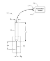
- FIG. 1 shows a schematic of an ophthalmic endoilluminator system according to a particular embodiment of the present invention
- FIGS. 2A and 2B illustrate end views of complementary fiber connectors according to a particular embodiment of the present invention
- FIGS. 3A and 3B illustrate end views of complementary fiber connectors according to an alternative embodiment of the present invention
- FIG. 4 is a graph illustrating the in-plane illumination angle corresponding to full-width at half maximum intensity for various amounts of decentration for a probe according to a particular embodiment of the present invention.
- FIG. 5 is a graph illustrating coupling efficiency for various amounts of decentration for a probe according to a particular embodiment of the present invention.
- Various embodiments of the present invention provide a fiber connector system with a decentered launch of light beams into the probe optical fiber.
- Certain embodiments include a source fiber connector and a probe fiber connector, wherein an illumination spot emitted from the source fiber connector is offset from a center of the probe fiber.
- the connectors can hold the central axes of the source emitter and the probe fiber offset relative to one another.
- the source emitter can be configured to emit an illumination spot off center relative to the probe fiber. Additional features of various embodiments of the present invention are described in the following explanation of the FIGs.
- Various embodiments of the present invention provide improve endoillumination by increasing the angular distribution of the illuminated area using a decentered launch while providing equivalent or greater coupling efficiency for the illumination source to the probe.
- Previous systems have centered the illumination spot on the probe fiber in order to avoid significant drops in coupling efficiency, therefore making less light available for illumination.
- the spot can be decentered without significant illumination loss. The decentration does, however, significantly increase the angular distribution of the illumination, thus allowing a wider area to be illuminated with substantially equal brightness.
- the illumination spot produced by the illumination source can be relatively large, meaning that decentering the spot produces significantly less illumination.
- illuminator systems using a tightly focused spot according to various embodiments of the present invention are used, decentration can be exploited for a larger angular distribution without such losses.
- various embodiments of the present invention may be particularly useful for illumination sources that produce tightly focused illumination spots, such as supercontinuum lasers.
- FIG. 1 which includes an endoprobe 10 with a handle 12 having a length L 1 suitable for being held in a single hand and cannula 14 having a diameter D and length L 2 .
- the endoprobe 10 is optically coupled to an illumination source 16 by a probe fiber connector 104 connected to a source fiber connector 102 .
- the diameter D of the cannula 14 is typically measured in according to the gauge system for needles and similar medical devices; for ophthalmic applications, this is typically 20 Ga (0.84 mm) or less. While the discussion relates to ophthalmic endoilluminators, it could also apply to similar endoillumination devices that are inserted through small incisions to produce wide-angle illumination. For purposes of this specification, “small gauge” will be used to refer to endoilluminators of 20 Ga diameter or less, and “nano-scale” will be used to refer to optical fibers having an outer diameter of 100 ⁇ m or less.
- FIGS. 2A and 2B illustrate end views of complementary fiber connectors 102 and 104 according to a particular embodiment of the present invention.
- the source connector 102 includes a bulkhead 106 for holding a probe fiber connector 104 in alignment with the illumination spot 108 produced by the illumination source 20 .
- the location of the illumination spot 108 is focused off-center relative to the bulkhead 106 , so that when the probe fiber connector 104 is centered by the bulkhead, the illumination spot 108 will enter a fiber core 110 of a probe optical fiber (including core 110 and cladding 112 ) decentered.
- FIGS. 3A and 3B An alternative embodiment is illustrated in FIGS. 3A and 3B .
- the probe fiber is positioned off-center in the probe fiber connector 104 .
- the probe fiber connector 104 When the probe fiber connector 104 is inserted into the bulkhead, it is automatically aligned so that a centered illumination spot 108 from the illumination source 20 will be off-center relative to the fiber core 110 of the probe fiber, as shown in FIG. 4B .
- the alignment of the source fiber connector 102 and the probe fiber connector 104 produces a decentered launch of illumination light into the probe fiber.
- FIG. 4 illustrates the in-plane angular distribution to full-width at half maximum (FWHM) of light intensity as measured from an example probe fiber into which an illumination spot is aligned for a decentered launch into the fiber.
- FWHM full-width at half maximum
- light emitted from an endoilluminator will be considered as having an “angular distribution” of a certain angle if the in-plane angular distribution to FWHM spans that angle.
- the illumination spot size is about 1 ⁇ m into a fiber having a numerical aperture of 0.22.
- the plot illustrates that for decentration of up to 20 ⁇ m, the angular distribution out to which the FWHM extends rises from about 70 degrees to nearly 90 degrees.
- FIG. 5 illustrates the coupling efficiency for the same optical fiber as a function of decentration.
- decentration of the illumination spot coupled into the fiber can actually increase slightly as long as the illumination spot still falls onto the fiber core, falling off only when the spot moves off of the fiber core.
- the decentered alignment of the endoilluminator system may provide a larger angular distribution without even needing to make the relatively minor tradeoff between brightness and angular intensity.
- Various embodiments of the present invention provide an endoilluminator system including fiber connectors providing a decentered alignment between an illumination spot and a probe optical fiber.
- Embodiments of the invention described above are exemplary only. One skilled in the art may recognize various alternative embodiments from those specifically disclosed. Those alternative embodiments are also intended to be within the scope of this disclosure. As such, the invention is limited only by the following claims.
Abstract
Description
Claims (6)
Priority Applications (1)
| Application Number | Priority Date | Filing Date | Title |
|---|---|---|---|
| US13/571,074 US9730576B2 (en) | 2011-08-09 | 2012-08-09 | Endoillumination using decentered fiber launch |
Applications Claiming Priority (2)
| Application Number | Priority Date | Filing Date | Title |
|---|---|---|---|
| US201161521450P | 2011-08-09 | 2011-08-09 | |
| US13/571,074 US9730576B2 (en) | 2011-08-09 | 2012-08-09 | Endoillumination using decentered fiber launch |
Publications (2)
| Publication Number | Publication Date |
|---|---|
| US20130041233A1 US20130041233A1 (en) | 2013-02-14 |
| US9730576B2 true US9730576B2 (en) | 2017-08-15 |
Family
ID=47668965
Family Applications (1)
| Application Number | Title | Priority Date | Filing Date |
|---|---|---|---|
| US13/571,074 Active 2034-02-05 US9730576B2 (en) | 2011-08-09 | 2012-08-09 | Endoillumination using decentered fiber launch |
Country Status (8)
| Country | Link |
|---|---|
| US (1) | US9730576B2 (en) |
| EP (1) | EP2720601B1 (en) |
| JP (1) | JP6114272B2 (en) |
| CN (1) | CN103732122B (en) |
| AU (1) | AU2012294363B2 (en) |
| CA (1) | CA2842435C (en) |
| ES (1) | ES2628304T3 (en) |
| WO (1) | WO2013023080A1 (en) |
Cited By (1)
| Publication number | Priority date | Publication date | Assignee | Title |
|---|---|---|---|---|
| US10918522B2 (en) | 2017-06-08 | 2021-02-16 | Alcon Inc. | Photodisruption-based vitrectomy system |
Families Citing this family (4)
| Publication number | Priority date | Publication date | Assignee | Title |
|---|---|---|---|---|
| US9849034B2 (en) | 2011-11-07 | 2017-12-26 | Alcon Research, Ltd. | Retinal laser surgery |
| US9097616B2 (en) * | 2013-01-25 | 2015-08-04 | Hewlett-Packard Development Company, L.P. | Apparatus for collecting material to be spectrally analyzed |
| US9572629B1 (en) * | 2015-08-31 | 2017-02-21 | Novartis Ag | Sub-micron alignment of a monitoring fiber for optical feedback in an ophthalmic endo-illumination system |
| EP3893824A4 (en) * | 2018-12-13 | 2022-09-21 | IOPtima Ltd. | Methods and systems for laser assisted technology for minimally-invasive ab-interno glaucoma surgery |
Citations (14)
| Publication number | Priority date | Publication date | Assignee | Title |
|---|---|---|---|---|
| US4870952A (en) * | 1983-10-28 | 1989-10-03 | Miquel Martinez | Fiber optic illuminator for use in surgery |
| US5283718A (en) | 1991-08-30 | 1994-02-01 | Progressive Dynamics, Inc. | Fiber optic arc lamp system |
| EP1039321A2 (en) | 1999-03-24 | 2000-09-27 | Lucent Technologies Inc. | Optical fiber ferrule apparatus |
| JP2002231008A (en) | 2001-02-05 | 2002-08-16 | Matsushita Electric Works Ltd | Lighting device |
| US20020149924A1 (en) | 2000-12-21 | 2002-10-17 | Waqidi Falicoff | Optical transformer for small light sources |
| US6478478B1 (en) | 2000-12-04 | 2002-11-12 | Patrick J. Campbell | Fiber-optic connector |
| US20050152643A1 (en) | 2004-01-12 | 2005-07-14 | Blauvelt Henry A. | Apparatus and methods for launching an optical signal into multimode optical fiber |
| US20050259916A1 (en) | 2003-05-21 | 2005-11-24 | David Jenkins | Multimode fiber optical fiber transmission system with offset launch single mode long wavelength vertical cavity surface emitting laser transmitter |
| US20060285796A1 (en) | 2005-06-16 | 2006-12-21 | Matsushita Electric Industrial Co., Ltd. | Coupling method for coupling high power optical beams into an optical waveguide |
| US20090227993A1 (en) | 2008-01-08 | 2009-09-10 | Cornova, Inc. | Shaped fiber ends and methods of making same |
| US20090232438A1 (en) * | 2008-03-17 | 2009-09-17 | Fujifilm Corporation | Low-speckle light source device |
| US20110015528A1 (en) | 2009-07-15 | 2011-01-20 | Hoya Corporation | Medical observation system and processor |
| US20110085348A1 (en) | 2009-10-13 | 2011-04-14 | Dobson Paul J | LED light source for fiber optic cable |
| US20110112377A1 (en) | 2009-11-11 | 2011-05-12 | Papac Michael J | Structured illumination probe and method |
Family Cites Families (3)
| Publication number | Priority date | Publication date | Assignee | Title |
|---|---|---|---|---|
| JPH0434504A (en) * | 1990-05-31 | 1992-02-05 | Furukawa Electric Co Ltd:The | Optical fiber for detecting gas, liquid or the like |
| JP2005168770A (en) * | 2003-12-10 | 2005-06-30 | Olympus Corp | Endoscope |
| CN201352265Y (en) * | 2008-11-21 | 2009-11-25 | 深圳市大族激光科技股份有限公司 | Optical fiber transmission device |
-
2012
- 2012-08-09 CA CA2842435A patent/CA2842435C/en not_active Expired - Fee Related
- 2012-08-09 US US13/571,074 patent/US9730576B2/en active Active
- 2012-08-09 AU AU2012294363A patent/AU2012294363B2/en not_active Ceased
- 2012-08-09 ES ES12822713.9T patent/ES2628304T3/en active Active
- 2012-08-09 EP EP12822713.9A patent/EP2720601B1/en active Active
- 2012-08-09 JP JP2014525150A patent/JP6114272B2/en active Active
- 2012-08-09 WO PCT/US2012/050180 patent/WO2013023080A1/en active Application Filing
- 2012-08-09 CN CN201280038755.XA patent/CN103732122B/en not_active Expired - Fee Related
Patent Citations (16)
| Publication number | Priority date | Publication date | Assignee | Title |
|---|---|---|---|---|
| US4870952A (en) * | 1983-10-28 | 1989-10-03 | Miquel Martinez | Fiber optic illuminator for use in surgery |
| US5283718A (en) | 1991-08-30 | 1994-02-01 | Progressive Dynamics, Inc. | Fiber optic arc lamp system |
| EP1039321A2 (en) | 1999-03-24 | 2000-09-27 | Lucent Technologies Inc. | Optical fiber ferrule apparatus |
| US6478478B1 (en) | 2000-12-04 | 2002-11-12 | Patrick J. Campbell | Fiber-optic connector |
| US20020149924A1 (en) | 2000-12-21 | 2002-10-17 | Waqidi Falicoff | Optical transformer for small light sources |
| JP2002231008A (en) | 2001-02-05 | 2002-08-16 | Matsushita Electric Works Ltd | Lighting device |
| US20050259916A1 (en) | 2003-05-21 | 2005-11-24 | David Jenkins | Multimode fiber optical fiber transmission system with offset launch single mode long wavelength vertical cavity surface emitting laser transmitter |
| US7231114B2 (en) * | 2003-05-21 | 2007-06-12 | Ocp-Europe, Ltd. | Multimode fiber optical fiber transmission system with offset launch single mode long wavelength vertical cavity surface emitting laser transmitter |
| WO2005067573A2 (en) | 2004-01-12 | 2005-07-28 | Xponent Photonics Inc | Apparatus and methods for launching an optical signal into multimode optical fiber |
| US20050152643A1 (en) | 2004-01-12 | 2005-07-14 | Blauvelt Henry A. | Apparatus and methods for launching an optical signal into multimode optical fiber |
| US20060285796A1 (en) | 2005-06-16 | 2006-12-21 | Matsushita Electric Industrial Co., Ltd. | Coupling method for coupling high power optical beams into an optical waveguide |
| US20090227993A1 (en) | 2008-01-08 | 2009-09-10 | Cornova, Inc. | Shaped fiber ends and methods of making same |
| US20090232438A1 (en) * | 2008-03-17 | 2009-09-17 | Fujifilm Corporation | Low-speckle light source device |
| US20110015528A1 (en) | 2009-07-15 | 2011-01-20 | Hoya Corporation | Medical observation system and processor |
| US20110085348A1 (en) | 2009-10-13 | 2011-04-14 | Dobson Paul J | LED light source for fiber optic cable |
| US20110112377A1 (en) | 2009-11-11 | 2011-05-12 | Papac Michael J | Structured illumination probe and method |
Non-Patent Citations (2)
| Title |
|---|
| International Search Report, PCT/US2012/050180, International Searching Authority, Oct. 16, 2012, 2 pgs. |
| Written Opinion, PCT/US2012/050180, International Searching Authority, Oct. 16, 2012, 5 pgs. |
Cited By (1)
| Publication number | Priority date | Publication date | Assignee | Title |
|---|---|---|---|---|
| US10918522B2 (en) | 2017-06-08 | 2021-02-16 | Alcon Inc. | Photodisruption-based vitrectomy system |
Also Published As
| Publication number | Publication date |
|---|---|
| JP6114272B2 (en) | 2017-04-12 |
| CA2842435A1 (en) | 2013-02-14 |
| EP2720601A4 (en) | 2015-01-21 |
| EP2720601A1 (en) | 2014-04-23 |
| EP2720601B1 (en) | 2017-05-03 |
| CA2842435C (en) | 2019-09-03 |
| US20130041233A1 (en) | 2013-02-14 |
| WO2013023080A1 (en) | 2013-02-14 |
| AU2012294363A1 (en) | 2014-02-06 |
| AU2012294363B2 (en) | 2017-02-16 |
| CN103732122A (en) | 2014-04-16 |
| JP2014528760A (en) | 2014-10-30 |
| CN103732122B (en) | 2017-02-22 |
| ES2628304T3 (en) | 2017-08-02 |
Similar Documents
| Publication | Publication Date | Title |
|---|---|---|
| US9730576B2 (en) | Endoillumination using decentered fiber launch | |
| JP4616269B2 (en) | Adapter for connecting a laser therapy device to an object | |
| US8380037B2 (en) | Lateral light emitting device and method of producing the same | |
| EP2498709B1 (en) | Structured illumination probe | |
| US8485972B2 (en) | Structured illumination probe and method | |
| JP6630697B2 (en) | Laser video endoscope | |
| US20090012511A1 (en) | Surgical waveguide | |
| WO2015174289A1 (en) | Endoscopic system | |
| US20090270682A1 (en) | Surgical instrument | |
| EP2169435A2 (en) | Waveguides with aiming mechanisms | |
| CN102202594B (en) | Surgical laser tip apparatus with alignment assembly | |
| KR20130127482A (en) | Optical coherence tomography and illumination using common light source | |
| JP2006204341A (en) | Light source device | |
| US20160066777A1 (en) | Application of highly scattering materials to surgical illumination | |
| US8128231B2 (en) | Enhanced lifetime illuminator | |
| JP2012128018A (en) | Hollow waveguide and laser therapeutic device | |
| US8995477B2 (en) | Ultrashort pulse laser processing apparatus | |
| US20190282327A1 (en) | Medical device inspection scope | |
| JP7462285B2 (en) | Optical probe and tip unit for optical probe | |
| US20240102887A1 (en) | Method for testing an orientation of a distal end of an optical fiber and test device therefor | |
| JP2005296379A (en) | Treating tool for endoscope and treating tool system for endoscope | |
| CN117598650A (en) | Endoscope system and control method |
Legal Events
| Date | Code | Title | Description |
|---|---|---|---|
| AS | Assignment |
Owner name: ALCON RESEARCH, LTD., TEXAS Free format text: ASSIGNMENT OF ASSIGNORS INTEREST;ASSIGNORS:YADLOWSKY, MICHAEL J.;PAPAC, MICHAEL;SIGNING DATES FROM 20120716 TO 20120816;REEL/FRAME:031603/0936 |
|
| STCF | Information on status: patent grant |
Free format text: PATENTED CASE |
|
| AS | Assignment |
Owner name: ALCON INC., SWITZERLAND Free format text: CONFIRMATORY DEED OF ASSIGNMENT EFFECTIVE APRIL 8, 2019;ASSIGNOR:NOVARTIS AG;REEL/FRAME:051454/0788 Effective date: 20191111 |
|
| AS | Assignment |
Owner name: ALCON RESEARCH, LLC, TEXAS Free format text: MERGER;ASSIGNOR:ALCON RESEARCH, LTD.;REEL/FRAME:053273/0022 Effective date: 20190228 |
|
| AS | Assignment |
Owner name: ALCON INC., SWITZERLAND Free format text: CONFIRMATORY DEED OF ASSIGNMENT EFFECTIVE APRIL 8, 2019;ASSIGNOR:ALCON RESEARCH, LLC;REEL/FRAME:053293/0484 Effective date: 20200619 |
|
| MAFP | Maintenance fee payment |
Free format text: PAYMENT OF MAINTENANCE FEE, 4TH YEAR, LARGE ENTITY (ORIGINAL EVENT CODE: M1551); ENTITY STATUS OF PATENT OWNER: LARGE ENTITY Year of fee payment: 4 |