US9722667B2 - Proximity sensing using EHF signals - Google Patents
Proximity sensing using EHF signals Download PDFInfo
- Publication number
- US9722667B2 US9722667B2 US15/263,362 US201615263362A US9722667B2 US 9722667 B2 US9722667 B2 US 9722667B2 US 201615263362 A US201615263362 A US 201615263362A US 9722667 B2 US9722667 B2 US 9722667B2
- Authority
- US
- United States
- Prior art keywords
- signal
- transducer
- circuit
- proximity
- ehf
- Prior art date
- Legal status (The legal status is an assumption and is not a legal conclusion. Google has not performed a legal analysis and makes no representation as to the accuracy of the status listed.)
- Active
Links
- 238000004891 communication Methods 0.000 claims abstract description 118
- 239000002131 composite material Substances 0.000 claims description 44
- 238000001514 detection method Methods 0.000 claims description 23
- 238000000034 method Methods 0.000 claims description 20
- 230000008859 change Effects 0.000 claims description 14
- 238000001228 spectrum Methods 0.000 claims description 4
- 230000001131 transforming effect Effects 0.000 claims 1
- 239000004020 conductor Substances 0.000 description 56
- 239000000758 substrate Substances 0.000 description 15
- 230000008878 coupling Effects 0.000 description 13
- 238000010168 coupling process Methods 0.000 description 13
- 238000005859 coupling reaction Methods 0.000 description 13
- 239000000463 material Substances 0.000 description 13
- 238000010586 diagram Methods 0.000 description 9
- 230000004044 response Effects 0.000 description 8
- 230000010355 oscillation Effects 0.000 description 5
- PXAGFNRKXSYIHU-UHFFFAOYSA-N 1,3-dichloro-2-(2,6-dichlorophenyl)benzene Chemical compound ClC1=CC=CC(Cl)=C1C1=C(Cl)C=CC=C1Cl PXAGFNRKXSYIHU-UHFFFAOYSA-N 0.000 description 4
- 230000009977 dual effect Effects 0.000 description 4
- 238000004519 manufacturing process Methods 0.000 description 4
- 238000005259 measurement Methods 0.000 description 4
- 230000005540 biological transmission Effects 0.000 description 3
- 238000004804 winding Methods 0.000 description 3
- 230000008901 benefit Effects 0.000 description 2
- 230000015556 catabolic process Effects 0.000 description 2
- 238000006731 degradation reaction Methods 0.000 description 2
- 239000011810 insulating material Substances 0.000 description 2
- 239000004065 semiconductor Substances 0.000 description 2
- 230000003321 amplification Effects 0.000 description 1
- 239000000969 carrier Substances 0.000 description 1
- 239000000919 ceramic Substances 0.000 description 1
- 238000006243 chemical reaction Methods 0.000 description 1
- 150000001875 compounds Chemical class 0.000 description 1
- 238000013461 design Methods 0.000 description 1
- 238000011161 development Methods 0.000 description 1
- 230000000694 effects Effects 0.000 description 1
- 238000010292 electrical insulation Methods 0.000 description 1
- 238000005538 encapsulation Methods 0.000 description 1
- 238000005516 engineering process Methods 0.000 description 1
- 230000002708 enhancing effect Effects 0.000 description 1
- 230000003631 expected effect Effects 0.000 description 1
- 239000011521 glass Substances 0.000 description 1
- 238000002955 isolation Methods 0.000 description 1
- 238000001465 metallisation Methods 0.000 description 1
- 238000003199 nucleic acid amplification method Methods 0.000 description 1
- 239000004033 plastic Substances 0.000 description 1
- 238000012545 processing Methods 0.000 description 1
- 230000000644 propagated effect Effects 0.000 description 1
- 229910052710 silicon Inorganic materials 0.000 description 1
- 239000010703 silicon Substances 0.000 description 1
- 229910000679 solder Inorganic materials 0.000 description 1
Images


Classifications
-
- H04B5/70—
-
- H—ELECTRICITY
- H04—ELECTRIC COMMUNICATION TECHNIQUE
- H04B—TRANSMISSION
- H04B5/00—Near-field transmission systems, e.g. inductive loop type
- H04B5/0025—Near field system adaptations
-
- G—PHYSICS
- G01—MEASURING; TESTING
- G01S—RADIO DIRECTION-FINDING; RADIO NAVIGATION; DETERMINING DISTANCE OR VELOCITY BY USE OF RADIO WAVES; LOCATING OR PRESENCE-DETECTING BY USE OF THE REFLECTION OR RERADIATION OF RADIO WAVES; ANALOGOUS ARRANGEMENTS USING OTHER WAVES
- G01S13/00—Systems using the reflection or reradiation of radio waves, e.g. radar systems; Analogous systems using reflection or reradiation of waves whose nature or wavelength is irrelevant or unspecified
- G01S13/02—Systems using reflection of radio waves, e.g. primary radar systems; Analogous systems
- G01S13/04—Systems determining presence of a target
-
- G—PHYSICS
- G01—MEASURING; TESTING
- G01S—RADIO DIRECTION-FINDING; RADIO NAVIGATION; DETERMINING DISTANCE OR VELOCITY BY USE OF RADIO WAVES; LOCATING OR PRESENCE-DETECTING BY USE OF THE REFLECTION OR RERADIATION OF RADIO WAVES; ANALOGOUS ARRANGEMENTS USING OTHER WAVES
- G01S13/00—Systems using the reflection or reradiation of radio waves, e.g. radar systems; Analogous systems using reflection or reradiation of waves whose nature or wavelength is irrelevant or unspecified
- G01S13/02—Systems using reflection of radio waves, e.g. primary radar systems; Analogous systems
- G01S13/06—Systems determining position data of a target
- G01S13/08—Systems for measuring distance only
-
- H—ELECTRICITY
- H04—ELECTRIC COMMUNICATION TECHNIQUE
- H04B—TRANSMISSION
- H04B5/00—Near-field transmission systems, e.g. inductive loop type
-
- H—ELECTRICITY
- H04—ELECTRIC COMMUNICATION TECHNIQUE
- H04B—TRANSMISSION
- H04B5/00—Near-field transmission systems, e.g. inductive loop type
- H04B5/0025—Near field system adaptations
- H04B5/005—Near field system adaptations for isolation purposes
-
- H04B5/75—
-
- H—ELECTRICITY
- H01—ELECTRIC ELEMENTS
- H01L—SEMICONDUCTOR DEVICES NOT COVERED BY CLASS H10
- H01L2224/00—Indexing scheme for arrangements for connecting or disconnecting semiconductor or solid-state bodies and methods related thereto as covered by H01L24/00
- H01L2224/01—Means for bonding being attached to, or being formed on, the surface to be connected, e.g. chip-to-package, die-attach, "first-level" interconnects; Manufacturing methods related thereto
- H01L2224/42—Wire connectors; Manufacturing methods related thereto
- H01L2224/47—Structure, shape, material or disposition of the wire connectors after the connecting process
- H01L2224/48—Structure, shape, material or disposition of the wire connectors after the connecting process of an individual wire connector
- H01L2224/481—Disposition
- H01L2224/48151—Connecting between a semiconductor or solid-state body and an item not being a semiconductor or solid-state body, e.g. chip-to-substrate, chip-to-passive
- H01L2224/48221—Connecting between a semiconductor or solid-state body and an item not being a semiconductor or solid-state body, e.g. chip-to-substrate, chip-to-passive the body and the item being stacked
- H01L2224/48225—Connecting between a semiconductor or solid-state body and an item not being a semiconductor or solid-state body, e.g. chip-to-substrate, chip-to-passive the body and the item being stacked the item being non-metallic, e.g. insulating substrate with or without metallisation
- H01L2224/48227—Connecting between a semiconductor or solid-state body and an item not being a semiconductor or solid-state body, e.g. chip-to-substrate, chip-to-passive the body and the item being stacked the item being non-metallic, e.g. insulating substrate with or without metallisation connecting the wire to a bond pad of the item
-
- H—ELECTRICITY
- H01—ELECTRIC ELEMENTS
- H01L—SEMICONDUCTOR DEVICES NOT COVERED BY CLASS H10
- H01L2224/00—Indexing scheme for arrangements for connecting or disconnecting semiconductor or solid-state bodies and methods related thereto as covered by H01L24/00
- H01L2224/01—Means for bonding being attached to, or being formed on, the surface to be connected, e.g. chip-to-package, die-attach, "first-level" interconnects; Manufacturing methods related thereto
- H01L2224/42—Wire connectors; Manufacturing methods related thereto
- H01L2224/47—Structure, shape, material or disposition of the wire connectors after the connecting process
- H01L2224/49—Structure, shape, material or disposition of the wire connectors after the connecting process of a plurality of wire connectors
- H01L2224/491—Disposition
- H01L2224/4911—Disposition the connectors being bonded to at least one common bonding area, e.g. daisy chain
- H01L2224/49111—Disposition the connectors being bonded to at least one common bonding area, e.g. daisy chain the connectors connecting two common bonding areas, e.g. Litz or braid wires
-
- H—ELECTRICITY
- H01—ELECTRIC ELEMENTS
- H01L—SEMICONDUCTOR DEVICES NOT COVERED BY CLASS H10
- H01L2224/00—Indexing scheme for arrangements for connecting or disconnecting semiconductor or solid-state bodies and methods related thereto as covered by H01L24/00
- H01L2224/01—Means for bonding being attached to, or being formed on, the surface to be connected, e.g. chip-to-package, die-attach, "first-level" interconnects; Manufacturing methods related thereto
- H01L2224/42—Wire connectors; Manufacturing methods related thereto
- H01L2224/47—Structure, shape, material or disposition of the wire connectors after the connecting process
- H01L2224/49—Structure, shape, material or disposition of the wire connectors after the connecting process of a plurality of wire connectors
- H01L2224/491—Disposition
- H01L2224/4911—Disposition the connectors being bonded to at least one common bonding area, e.g. daisy chain
- H01L2224/49113—Disposition the connectors being bonded to at least one common bonding area, e.g. daisy chain the connectors connecting different bonding areas on the semiconductor or solid-state body to a common bonding area outside the body, e.g. converging wires
-
- H—ELECTRICITY
- H01—ELECTRIC ELEMENTS
- H01L—SEMICONDUCTOR DEVICES NOT COVERED BY CLASS H10
- H01L2224/00—Indexing scheme for arrangements for connecting or disconnecting semiconductor or solid-state bodies and methods related thereto as covered by H01L24/00
- H01L2224/01—Means for bonding being attached to, or being formed on, the surface to be connected, e.g. chip-to-package, die-attach, "first-level" interconnects; Manufacturing methods related thereto
- H01L2224/42—Wire connectors; Manufacturing methods related thereto
- H01L2224/47—Structure, shape, material or disposition of the wire connectors after the connecting process
- H01L2224/49—Structure, shape, material or disposition of the wire connectors after the connecting process of a plurality of wire connectors
- H01L2224/491—Disposition
- H01L2224/4912—Layout
- H01L2224/49171—Fan-out arrangements
-
- H—ELECTRICITY
- H01—ELECTRIC ELEMENTS
- H01L—SEMICONDUCTOR DEVICES NOT COVERED BY CLASS H10
- H01L2924/00—Indexing scheme for arrangements or methods for connecting or disconnecting semiconductor or solid-state bodies as covered by H01L24/00
-
- H—ELECTRICITY
- H01—ELECTRIC ELEMENTS
- H01L—SEMICONDUCTOR DEVICES NOT COVERED BY CLASS H10
- H01L2924/00—Indexing scheme for arrangements or methods for connecting or disconnecting semiconductor or solid-state bodies as covered by H01L24/00
- H01L2924/0001—Technical content checked by a classifier
- H01L2924/00012—Relevant to the scope of the group, the symbol of which is combined with the symbol of this group
-
- H—ELECTRICITY
- H01—ELECTRIC ELEMENTS
- H01L—SEMICONDUCTOR DEVICES NOT COVERED BY CLASS H10
- H01L2924/00—Indexing scheme for arrangements or methods for connecting or disconnecting semiconductor or solid-state bodies as covered by H01L24/00
- H01L2924/15—Details of package parts other than the semiconductor or other solid state devices to be connected
- H01L2924/181—Encapsulation
-
- H—ELECTRICITY
- H01—ELECTRIC ELEMENTS
- H01L—SEMICONDUCTOR DEVICES NOT COVERED BY CLASS H10
- H01L2924/00—Indexing scheme for arrangements or methods for connecting or disconnecting semiconductor or solid-state bodies as covered by H01L24/00
- H01L2924/30—Technical effects
- H01L2924/301—Electrical effects
- H01L2924/3011—Impedance
- H01L2924/30111—Impedance matching
Definitions
- This disclosure relates to systems and methods for EHF communications, including systems and methods for sensing proximity and determining distance.
- PCBs printed circuit boards
- Connector and backplane architectures introduce a variety of impedance discontinuities into the signal path, resulting in a degradation of signal quality or integrity.
- Connecting to boards by conventional means, such as signal-carrying mechanical connectors generally creates discontinuities, requiring expensive electronics to negotiate.
- Conventional mechanical connectors may also wear out over time, require precise alignment and manufacturing methods, and are susceptible to mechanical jostling.
- a system may include a first amplifier for amplifying an output signal having an EHF frequency.
- a transducer may be operatively coupled to the first amplifier for converting the amplified output signal into an electromagnetic signal having the EHF frequency.
- a proximity-sensing circuit may be included, responsive to a reference and a composite signal conducted between the first amplifier and the transducer, for sensing the proximity of a transducer field-modifying device proximate to the transducer.
- the composite signal may include the amplified output signal and any electromagnetic received signal received by the transducer and induced by the field-modifying device.
- An illustrative method may include amplifying by a first amplifier an output signal having an EHF frequency.
- a transducer may convert the amplified output signal into an electromagnetic signal having the EHF frequency.
- the proximity of a transducer field-modifying device proximate to the transducer may be sensed in response to a reference and a composite signal conducted between the first amplifier and the transducer.
- the composite signal may include the amplified output signal and any electromagnetic received signal received by the transducer and induced by the field-modifying device.
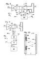
- FIG. 1 shows a simplified schematic overhead view of a first example of an integrated circuit (IC) package including a die and antenna.
- IC integrated circuit
- FIG. 2 shows a schematic side view of an exemplary communication device including an IC package and printed circuit board (PCB).
- PCB printed circuit board
- FIG. 3 shows an isometric view of another exemplary communication device including an IC package with external circuit conductors.
- FIG. 4 shows a bottom view of the exemplary communication device of FIG. 3 .
- FIG. 5 is a circuit diagram showing an exemplary proximity-sensing circuit.
- FIG. 6 is a circuit diagram showing another exemplary proximity-sensing circuit.
- FIG. 7 is a circuit diagram showing another exemplary proximity-sensing circuit.
- FIG. 8 is a circuit diagram showing another exemplary proximity-sensing circuit.
- FIG. 9 is a circuit diagram showing another exemplary proximity-sensing circuit.
- FIG. 10 shows an exemplary distance measuring system having two communications units and a field-modifying device.
- FIG. 11 is a block diagram of a variation of the system of FIG. 10 .
- FIG. 12 shows another exemplary distance measuring system having four communications units.
- FIG. 13 is a block diagram of the system of FIG. 12 .
- FIG. 14 is a flow chart showing an exemplary proximity-sensing method.
- FIG. 15 is a flow chart showing an exemplary distance-measuring method.
- Wireless communication may be used to provide signal communications between components on a device or may provide communication between devices. Wireless communication provides an interface that is not subject to mechanical and electrical degradation. Examples of systems employing wireless communication between chips are disclosed in U.S. Pat. No. 5,621,913 and U.S. Published Patent Application No. 2010/0159829, the disclosures of which are incorporated herein by reference in their entirety for all purposes.
- tightly-coupled transmitter/receiver pairs may be deployed with a transmitter disposed at a terminal portion of a first conduction path and a receiver disposed at a terminal portion of a second conduction path.
- the transmitter and receiver may be disposed in close proximity to each other depending on the strength of the transmitted energy, and the first conduction path and the second conduction path may be discontiguous with respect to each other.
- the transmitter and receiver may be disposed on separate circuit carriers positioned with the antennas of the transmitter/receiver pair in close proximity.
- a transmitter and/or receiver may be configured as an IC package, in which one or more antennas may be positioned adjacent to a die and held in place by a dielectric or insulating encapsulation or bond material. An antenna may also be held in place by a lead frame substrate. Examples of EHF antennas embedded in IC packages are shown in the drawings and described below. Note that IC packages may also be referred to as EHF IC packages or simply packages, and are examples of wireless communication units that are also variously referred to as EHF communication units, communication units, communication devices, comm-link chip packages, and/or comm-link packages.
- FIG. 1 shows an exemplary IC package, generally indicated at 10 .
- IC package 10 includes a chip or die 12 , a transducer 14 providing conversion between electrical and electromagnetic (EM) signals, and conductive connectors 16 , such as bond wires 18 , 20 electrically connecting the transducer to bond pads 22 , 24 connected to a transmitter or receiver circuit included in die 12 .
- IC package 10 further includes an encapsulating material 26 formed around at least a portion of the die and/or the transducer. In this example encapsulating material 26 covers die 12 , conductive connectors 16 , and transducer 14 , and is shown in phantom lines so that details of the die and transducer may be illustrated in solid lines.
- Die 12 includes any suitable structure configured as a miniaturized circuit on a suitable die substrate, and is functionally equivalent to a component also referred to as a chip or an integrated circuit (IC).
- a die substrate may be any suitable semiconductor material; for example, a die substrate may be silicon.
- Die 12 may have a length and a width dimension, each of which may be about 1.0 mm to about 2.0 mm, and preferably about 1.2 mm to about 1.5 mm. Die 12 may be mounted with further electrical conductors 16 , such as a lead frame, not shown in FIG. 1 , providing connection to external circuits.
- a transformer 28 shown in dashed lines, may provide impedance matching between a circuit on die 12 and transducer 14 .
- Transducer 14 may be in the form of a folded dipole or loop antenna 30 , may be configured to operate at radio frequencies such as in the EHF spectrum, and may be configured to transmit and/or receive electromagnetic signals.
- Antenna 30 is separate from but operatively connected to die 12 by suitable conductors 16 , and is located adjacent to die 12 .
- a loop configuration of antenna 30 includes a 0.1 mm band of material, laid out in a loop 1.4 mm long and 0.53 mm wide, with a gap of 0.1 mm at the mouth of the loop, and with the edge of the loop approximately 0.2 mm from the edge of die 12 .
- Encapsulating material 26 is used to assist in holding the various components of IC package 10 in fixed relative positions.
- Encapsulating material 26 may be any suitable material configured to provide electrical insulation and physical protection for the electrical and electronic components of IC package 10 .
- encapsulating material 26 also referred to as insulating material, may be a mold compound, glass, plastic, or ceramic.
- Encapsulating material 26 may also be formed in any suitable shape.
- encapsulating material 26 may be in the form of a rectangular block, encapsulating all components of IC package 10 except the unconnected ends of conductors 16 connecting the die to external circuits. External connections may be formed with other circuits or components.
- FIG. 2 shows a representational side view of a communication device 50 including an IC package 52 flip-mounted to an exemplary printed circuit board (PCB) 54 .
- IC package 52 includes a die 56 , a ground plane 57 , an antenna 58 , bond wires, including bond wire 60 , connecting the die to the antenna.
- the die, antenna, and bond wires are mounted on a package substrate 62 and encapsulated in encapsulating material 64 .
- Ground plane 57 may be mounted to a lower surface of die 56 , and may be any suitable structure configured to provide an electrical ground for the die.
- PCB 54 may include a top dielectric layer 66 having a major face or surface 68 .
- IC package 52 is flip-mounted to surface 68 with flip-mounting bumps 70 attached to a metallization pattern (not shown).
- PCB 54 may further include a layer 72 spaced from surface 68 made of conductive material forming a ground plane within PCB 54 .
- the PCB ground plane may be any suitable structure configured to provide an electrical ground to circuits and components on PCB 54 .
- FIGS. 3 and 4 illustrate another exemplary communication device 80 including an IC package 82 with external circuit conductors 84 and 86 .
- IC package 82 may include a die 88 , a lead frame 90 , conductive connectors 92 in the form of bond wires, an antenna 94 , encapsulating material 96 , and other components not shown to simplify the illustration.
- Die 88 may be mounted in electrical communication with lead frame 90 , which may be any suitable arrangement of electrical conductors or leads 98 configured to allow one or more other circuits to operatively connect with die 90 .
- Antenna 94 may be constructed as a part of the manufacturing process that produces lead frame 90 .
- Leads 98 may be embedded or fixed in a lead frame substrate 100 , shown in phantom lines, corresponding to package substrate 62 .
- the lead frame substrate may be any suitable insulating material configured to substantially hold leads 98 in a predetermined arrangement. Electrical communication between die 88 and leads 98 of lead frame 90 may be accomplished by any suitable method using conductive connectors 92 .
- conductive connectors 92 may include bond wires that electrically connect terminals on a circuit of die 88 with corresponding lead conductors 98 .
- a conductor or lead 98 may include a plated lead 102 formed on an upper surface of lead frame substrate 100 , a via 104 extending through the substrate, a flip-mounting bump 106 mounting IC package 82 to a circuit on a base substrate, such as a PCB, not shown.
- the circuit on the base substrate may include a external conductors, such as external conductor 84 , which for example, may include a strip conductor 108 connecting bump 106 to a further via 110 extending through the base substrate.
- Other vias 112 may extend through the lead frame substrate 100 and there may be additional vias 114 extending through the base substrate.
- die 88 may be inverted and conductive connectors 92 may include bumps, or die solder balls, as described previously, which may be configured to electrically connect points on a circuit of die 88 directly to corresponding leads 98 in what is commonly known as a “flip chip” arrangement.
- a first and a second IC package 10 may be co-located on a single PCB and may provide intra-PCB communication.
- a first IC package 10 may be located on a first PCB and a second IC package 10 may be located on a second PCB and may therefore provide inter-PCB communication.
- One method for enhancing or ensuring proper signal security and integrity is to verify a second IC package is within a predetermined range before or during a communication attempt. To that end, systems and methods for detecting the presence of a second IC package and/or for ensuring another device or surface is within a certain distance will now be described
- FIG. 5 is a circuit diagram showing an illustrative communication system or circuit generally indicated at 150 .
- communication circuit 150 may be at least partially included in the die of an IC package 154 and may be configured as a transmitter, similar to IC package 10 .
- Communication circuit 150 may also include a power amplifier 160 , a transformer 162 , a transducer in the form of an antenna 164 , and a proximity-sensing circuit 165 .
- Signal conductors 156 and 157 connect the power amplifier to the transformer, and signal conductors 158 and 159 connect the transformer to the antenna.
- Proximity-sensing circuit 165 may include a detection circuit 170 and sensing conductors 166 and 168 electrically connecting conductors 158 and 159 , respectively, to the detection circuit.
- proximity of a nearby object may be detected by a change in the effective impedance of antenna 164 caused by the nearby object.
- the object may be considered a transducer field-modifying device.
- a change in the effective impedance of the antenna may produce a change in a composite signal appearing on signal conductors 158 and 159 .
- Power amplifier 160 may be any suitable circuit configured to amplify an RF signal received on an input conductor 161 for transmission by antenna 164 . After amplification, signal conductors 156 and 157 may carry the RF signal through the primary winding of transformer 162 . Signal conductors 158 and 159 may then carry the transformed RF signal to antenna 164 .
- Transformer 162 may be any suitable transformer configured to accomplish impedance matching for improved RF signal strength at the antenna.
- detection circuit 170 may be connected via signal conductors 166 and 168 to signal conductors 158 and 159 at nodes 172 and 174 , respectively.
- Detection circuit 170 may detect a characteristic of a composite signal existing on signal conductors 158 and 159 , such as an amplitude of voltage of the composite RF signal.
- the composite signal may include the amplified and transformed RF output signal as well as any received signal received by antenna 164 .
- the detector circuit may thus detect any difference between the composite signal and the amplified RF signal that exists when the nearby object is in a reference position.
- a reference position may be at a predefined distance from the antenna where the nearby object produces an expected effect on the antenna, and the predefined distance may be a distance sufficient for the nearby object to not produce a predefined effect on the composite signal.
- An amplitude reference level may be provided on a reference conductor 176 to detection circuit 170 .
- detection circuit 170 compares the amplitude of the composite signal occurring at nodes 172 and 174 to the provided reference level on reference conductor 176 . Based on this comparison, a difference between the detected and the reference levels may indicate that an impedance of antenna 164 is different than expected. The amount of difference may be proportional to a reflected signal from a nearby object such as a second IC package or device. Based on the amplitude of the impedance change, a signal may then be generated and output on an indicator conductor 179 indicating the presence or absence of a nearby object. In some examples, this may indicate the presence or absence of a receiving IC package (not shown) suitable for receiving transmissions from IC package 154 .
- FIG. 6 shows another example of a communication system or circuit generally indicated at 180 .
- communication circuit 180 may be at least partially included in the die of an IC package 182 and may be configured as a transmitter, similar to IC packages 10 and 154 previously described.
- communication circuit 180 may also include a power amplifier 188 , a transformer 190 , a transducer in the form of an antenna 192 , and a proximity-sensing circuit 193 .
- Signal conductors 184 and 185 connect the power amplifier to the transformer, and signal conductors 186 and 187 connect the transformer to the antenna.
- proximity-sensing circuit 193 may include a detection circuit 194 similar to circuit 170 .
- detection circuit 194 detects an amplitude of voltage at nodes 198 and 200 .
- a reference level may be detectable by detection circuit 194 on a second circuit such as reference circuit 202 via conductors 204 and 205 .
- Reference circuit 202 may be a replica of a portion of communication circuit 180 . More specifically, reference circuit 202 may receive an RF signal that is also input to amplifier 188 on an input conductor 206 .
- Reference circuit 202 may include a replica power amplifier 208 substantially identical to power amplifier 188 , a replica transformer 210 substantially identical to transformer 190 , and an antenna equivalent 212 having an impedance that is substantially equal to that of antenna 192 when the nearby object is in the reference position.
- Antenna equivalent 212 may include terminals 214 and 216 that are disposed between transformer 210 and impedance 212 , as shown in FIG. 6 .
- reference circuit 202 may be configured to have the same input and substantially equivalent components as a corresponding portion of communication circuit 180 .
- Detection circuit 194 may therefore be configured to detect a reference amplitude of a voltage at terminals 214 and 216 , and communicate the reference amplitude as the reference level to detection circuit 194 via conductors 204 and 205 . That reference level may then be compared to the voltage detected at nodes 198 and 200 , and any difference may be proportional to an impedance change caused by the presence of a nearby object such as a second, receiving IC package (not shown). Based on a predetermined threshold or range of values, detection circuit 194 may then generate a signal on an indicator conductor 220 indicating the presence or absence of a nearby object. In some examples, this may indicate presence or absence of a receiving IC package (not shown) suitable for receiving transmissions from IC package 182 .
- a cancellation network may be configured using two resistive voltage dividers to cancel the transmitted signal portion of a detected signal, allowing any deviation from the expected transmitted signal to be detected as a change from zero.
- FIG. 7 shows an illustrative communication circuit generally indicated at 222 .
- communication circuit 222 may be at least partially located on the die of an IC package 224 configured as a transmitter, similar to IC packages 10 , 154 , and 182 previously described.
- communication circuit 222 may include a power amplifier 230 for amplifying an RF signal received on an input conductor 231 , a transformer 232 , a transducer in the form of an antenna 234 , and a proximity-sensing circuit 235 .
- Amplifier 230 may be connected to the primary winding of transformer 232 by conductors 226 and 227 , and the secondary windings of the transformer may be connected to antenna 234 by conductors 228 and 229 .
- proximity-sensing circuit 235 includes a cancellation network 236 connected to signal conductors 226 , 227 , 228 , and 229 across transformer 232 , and an amplitude detection circuit 238 connected to cancellation network 236 .
- Cancellation network 236 may include resistive voltage dividers 240 and 242 , each connected across transformer 232 .
- Resistive voltage divider 240 may include a first resistor 244 connected in series with a second resistor 246 , with a node 248 between the two resistors.
- resistive voltage divider 242 may include a first resistor 250 connected in series with a second resistor 252 , with a node 254 between the two resistors.
- Resistive voltage dividers 240 and 242 of cancellation network 236 may be configured such that a transmitted signal may be effectively cancelled by the network when measured at nodes 248 and 254 .
- resistance values of resistors 244 , 246 , 250 , and 252 may be chosen with respect to the coupling factor of transformer 232 such that a voltage 258 measured across nodes 248 and 254 is effectively zero when impedance of antenna 234 is at its expected value. This may be achieved by setting the ratio of the value of the second resistor to the sum of the value of the first and second resistors to approximate the coupling factor.
- the expected voltage across the nodes of the voltage dividers is effectively zero when antenna impedance is at an expected value corresponding to when the nearby object is in the reference position. Accordingly, any amplitude indicates variance from that value and therefore reflection of energy into the antenna. Reflection of this sort, in turn, indicates the presence of a second, nearby object or surface (not shown). Comparing the detected voltage to a predetermined value or range of values, a signal may be generated corresponding to either the presence or absence of an object or surface.
- amplitude detection circuit 238 may be any suitable circuit configured to detect the voltage across nodes 248 and 254 , and to generate an signal on an indicator conductor 260 responsive to the voltage detected.
- signal 260 may indicate the presence of a nearby object (not shown) in response to a non-zero value of the detected voltage.
- communication circuit 262 may be at least partially located on the die of an IC package 264 configured as a transmitter.
- communication circuit 262 may include a power amplifier 270 for amplifying an RF signal received on an input conductor 272 , a transducer in the form of an antenna 274 , and a proximity-sensing circuit 275 .
- communication circuit 262 may include an impedance circuit 273 , which may include series resistors, such as series resistors 276 and 278 disposed in signal conductors 266 and 268 , respectively, coupling the amplifier to the transducer.
- proximity-sensing circuit 275 includes a cancellation network 280 connected to signal conductors 266 and 268 across series resistors 276 and 278 , and an amplitude detection circuit 282 connected to cancellation network 280 .
- cancellation network 280 may include resistive voltage dividers 284 and 286 .
- Resistive voltage divider 284 may include a first resistor 288 connected in series with a second resistor 290 , with a node 292 in between, and resistive voltage divider 286 may include a first resistor 294 connected in series with a second resistor 296 , with a node 298 in between.
- resistive voltage dividers 284 and 286 may be configured as described above, but with resistance values chosen with respect to both antenna impedance and the resistance of resistors 276 and 278 to cause a measured voltage across nodes 292 and 298 to be zero if the expected antenna impedance exists. This may be achieved by setting the ratio of the value of the second resistor to the sum of the value of the first and second resistors to approximate the ratio of the antenna impedance to the sum of the antenna impedance and the resistance of a series resistor.
- amplitude detection circuit 282 may be any suitable circuit configured to measure voltage across nodes 292 and 298 , and to generate a signal on an indicator conductor 302 that is responsive to the voltage detected.
- the signal may indicate the presence of a nearby object (not shown) in response to a nonzero value of the voltage at nodes 292 and 298 .
- FIG. 9 shows another illustrative communication circuit generally indicated at 304 .
- communication circuit 304 may be at least partially located on the die of an IC package 306 configured as a transmitter, similar to IC packages previously described.
- communication circuit 304 may include a power amplifier 312 for amplifying an RF signal received on an input conductor 314 , a transformer 316 , a transducer in the form of an antenna 318 , and a proximity-sensing circuit 319 .
- a frequency detection circuit 320 may be connected to signal conductors 308 and 310 extending between power amplifier 312 and transformer 316 .
- Frequency detection circuit 320 may be any suitable circuit configured to sense a frequency of the signal being carried on signal conductors 308 and 310 , and to compare that sensed frequency to a reference value input on a reference conductor 324 .
- the reference value is representative of a frequency that would exist when the nearby object is in the reference position.
- the detection circuit generates a proximity indication signal on an indication conductor 325 in response to a result of the comparison.
- the presence of a nearby object sufficiently close to the antenna causes the frequency of the composite signal appearing on conductors 308 and 310 to vary based on the presence and proximity of the nearby object.
- frequency detection circuit 320 may include an isolation amplifier 326 connected to signal conductors 308 and 310 , providing output to a divider circuit 328 , which in turn may divide the signal to a more usable level and provide a sensed signal on a conductor 322 to a dual counter circuit 330 .
- Dual counter circuit 330 also receives the input reference signal on conductor 324 corresponding to the expected frequency value of the sensed signal when the nearby object is in the reference position.
- the proximity indication signal may be provided by the dual counter circuit to a controller 332 on conductor 325 .
- illustrative circuits using communication circuits formed in IC packages 10 are described which may be used to ensure two surfaces are at a desired spacing or within a desired spacing range, or to determine the actual or relative distance between two surfaces. For example, it may be desirable for a first device to detect that a second device is close enough for secure or unimpaired communications before the devices communicate. Combinations of IC packages 10 or other communication circuits may be utilized to perform this function.
- FIGS. 10 and 11 show examples of distance detecting systems in which reflected EHF signals may be used to determine a distance to a reflective surface.
- reflective measuring system 400 may include two IC packages 402 and 404 mounted near each other on a first surface 406 facing a second surface 408 .
- Second surface 408 may be reflective with respect to RF energy, and may have, for example, an electrically conductive surface.
- IC package 402 may be configured as a transmitter, with IC package 404 configured as a receiver.
- a transmitted EHF signal 410 transmitted by IC package 402 may be reflected by second surface 408 before being received as a reflected EHF signal 412 by IC package 404 .
- the circuitry may then analyze a relationship between the respective signals experienced by IC packages 402 and 404 , calculating an actual or relative distance between first surface 406 and second surface 408 , or determining an indicator signal representative of the distance between the surfaces. For example, a round-trip time of propagation of a signal that is transmitted and reflected may be calculated, which time of propagation is proportional to a distance D between the surfaces.
- an output 414 of receiver IC package 404 may be fed into an input 416 of transmitter IC package 402 .
- One of either IC package 402 or 404 may also be configured to invert the signal, such that a frequency of that inversion may be measured by a measuring circuit 418 , including a frequency counter, that is in communication with the input 416 of IC package 402 .
- This frequency is proportional to a propagation delay in the system. Because signal propagation time through the distance D between surfaces increases as the distance is widened, frequency and propagation delay has a relationship to the distance D between surfaces 406 and 408 , and a distance D is calculated based on the measured frequency. Accordingly, the examples of FIGS. 10 and 11 show that distance may be measured using a reflective measuring system 400 . Accordingly, measuring circuit 418 may generate an indicator signal representative of the distance D.
- FIGS. 12 and 13 show another illustrative distance measuring system generally indicated at 500 , having four IC packages 502 , 504 , 506 , 508 arranged on two surfaces 510 and 512 to form a ring oscillator 514 .
- Ring oscillator 514 may be configured such that IC package 502 on surface 510 transmits an electromagnetic (EM) EHF signal 516 that is received by IC package 504 on surface 512 .
- IC package 504 may be in electrical communication with IC package 506 , also located on surface 512 . Accordingly, EM signal 516 may be converted to signal 518 and directly fed into an input of IC package 506 .
- IC package 506 in turn, may be configured to transmit signal 518 as an EM EHF signal 520 to IC package 508 located on surface 510 .
- a delay in propagation time of the signal corresponding to signals 516 , 518 , and 520 is proportional to the variable distance D′ between surfaces 510 and 512 .
- an output 522 of IC package 508 may be fed directly into an input 524 of IC package 502 , and an odd number (i.e., one or three) of the IC packages may be wired as inverters. Because an odd number of the packages are thus wired to invert the signal, input signal 524 measured at IC package 502 would be inverted at a rate proportional to the overall propagation delay in ring oscillator 514 .
- a measuring circuit 526 such as one including a frequency counter, may measure the frequency of reversal or oscillation and calculate a distance between surfaces 510 and 512 based on that measurement.
- FIG. 14 shows an illustrative method 600 for determining proximity of a nearby object, as variously provided by circuits and systems previously described.
- Step 602 may include amplifying an RF output signal having an EHF frequency.
- Step 604 may include converting the amplified signal from step 602 into an electromagnetic signal.
- a transducer such as an antenna may be used to convert the signal to an EM signal.
- a nearby object may affect the field of the transducer, either directly or indirectly.
- Step 606 may include sensing the proximity of that transducer field-modifying device or object.
- FIG. 15 shows an illustrative method 700 for determining a distance between two surfaces, as variously provided by circuits and systems previously described.
- Step 702 may include transmitting an EHF signal from a first surface toward a second surface.
- the second surface may reflect the EHF signal, or may receive the EHF signal and retransmit a version of the signal in response.
- Step 704 may include receiving whatever signal is transmitted from the second surface, to include a reflected signal.
- Step 706 may include determining and indicating distance between the two surfaces based on a characteristic of the propagation of the signal between the two surfaces.
- a system or method as described above for proximity sensing and distance measurement using EHF signals may include one or more of the following examples.
- a system may include a first amplifier for amplifying an output signal having an EHF frequency.
- a transducer may be operatively coupled to the first amplifier for converting the amplified output signal into an electromagnetic signal having the EHF frequency.
- a proximity-sensing circuit may be included, responsive to a reference and a composite signal conducted between the first amplifier and the transducer, for sensing the proximity of a transducer field-modifying device proximate to the transducer.
- the composite signal may include the amplified output signal and any electromagnetic received signal received by the transducer and induced by the field-modifying device.
- the reference may be representative of a characteristic of the composite signal when the transducer field-modifying device is in a reference position.
- the proximity-sensing circuit may generate an indicator signal indicative of a change in the composite signal. More specifically, the reference may be a reference signal representative of the amplified output signal when the transducer field-modifying device is in a reference position.
- the proximity-sensing circuit may generate an indicator signal indicative of a composite signal including a received signal received by the transducer.
- the proximity-sensing circuit may compare an amplitude of the reference signal with an amplitude of the composite signal.
- the proximity-sensing circuit may include a reference circuit having a second amplifier and a terminating impedance coupled to an output of the amplifier, with the terminating impedance being substantially equivalent to an impedance of the transducer when the transducer field-modifying device is in the reference position.
- the reference circuit may generate the reference signal between the second amplifier and the terminating impedance.
- the reference may instead be representative of a frequency of the amplified output signal when the transducer field-modifying device is in a reference position.
- the proximity-sensing circuit may detect the frequency of the composite signal and produce the indicator signal indicative of when there is a change in the frequency of the composite signal.
- the reference signal may be a clock signal representative of the frequency of the amplified output signal when the transducer field-modifying device is in the reference position.
- the proximity-sensing circuit may include a dual counter responsive to a frequency signal representative of the frequency of the composite signal and the reference signal. The proximity-sensing circuit may produce the indicator signal indicative of a change in the frequency of the composite signal relative to the frequency of the amplified output signal when the transducer field-modifying device is in the reference position.
- the proximity-sensing circuit may include a cancellation circuit that cancels the amplified output signal from the composite signal.
- the system may further include an impedance circuit coupling the first amplifier with the transducer.
- the cancellation circuit may have first and second resistive voltage dividers connected in parallel with the impedance circuit. The resistive voltage dividers may produce relative voltages that effectively cancel an amplified output signal but do not cancel the received signal. The received signal may be detected on the resistive voltage dividers.
- the impedance circuit may include a transformer having a coupling factor
- the voltage dividers may include a first resistor connected to a first conductor coupling the first amplifier to the transformer and a second resistor connected to a second conductor coupling the transformer to the transducer, the ratio of a resistance of the second resistor to the sum of resistances of the first and second resistors is proportional to the coupling factor of the transformer.
- the impedance circuit may include an in-line resistor and the voltage dividers may include a first resistor connected between the in-line resistor and the first amplifier and a second resistor connected between the in-line resistor and the transducer, and the ratio of a resistance of the second resistor to the sum of resistances of the first and second resistors is proportional to the ratio of an impedance of the transducer to the sum of impedances of the transducer and the in-line resistor.
- a system may include a first transmit communication unit mounted on a first surface for transmitting a receive EHF signal toward a second surface spaced from the first surface.
- a first receive communication unit may be mounted on the first surface adjacent the first transmit communication unit for receiving a receive EHF signal transmitted from the second surface.
- a detecting circuit coupled to the first transmit communication unit and the first receive communication unit may determine an indicator representative of a distance between the first and second surfaces based on the propagation of the transmit and receive EHF signals between the first transmit communication unit and the first receive communication unit.
- the detecting circuit may determine from signals representative of the transmit and receive EHF signals, a time representative of the time of propagation of the transmit and receive EHF signals between the first transmit communication unit and the first receive communication unit.
- the transmit EHF signal may reflect off of the second surface and propagate as the receive EHF signal toward the first receive communication unit.
- the transmit and receive EHF signals may be modulated and the detecting circuit may be responsive to a modulation signal input to the first transmit communication unit and a demodulation signal output from the first transmit communication unit.
- the system may further include a second transmit communication unit and a second receive communication unit mounted on the second surface.
- the first transmit communication unit may transmit the transmit EHF signal to the second receive communication unit.
- the second receive communication unit may be coupled to the second transmit communication unit and may communicate a communication signal representative of the transmit EHF signal received by the second receive communication unit to the second transmit communication unit.
- the second transmit communication unit may transmit to the first receive communication unit the receive EHF signal representative of the communication signal.
- the first receive communication unit may be coupled to the first transmit communication unit, with the first and second transmit communication units and first and second receive communication units forming in combination a ring oscillator.
- the detecting circuit may determine an oscillation period of the ring oscillator, the oscillation period being related to a distance between the first surface and the second surface.
- the transmit and receive EHF signals may instead be modulated, and the detecting circuit may be responsive to a modulation signal input to the first transmit communication unit and a demodulation signal output from the first transmit communication unit.
- An illustrative method may include amplifying by a first amplifier an output signal having an EHF frequency.
- a transducer may convert the amplified output signal into an electromagnetic signal having the EHF frequency.
- the proximity of a transducer field-modifying device proximate to the transducer may be sensed in response to a reference and a composite signal conducted between the first amplifier and the transducer.
- the composite signal may include the amplified output signal and any electromagnetic received signal received by the transducer and induced by the field-modifying device.
- the reference may be representative of a characteristic of the composite signal when the transducer field-modifying device is in a reference position, an indicator signal may be generated indicative of a change in the composite signal.
- the reference may be a reference signal representative of the amplified output signal when the transducer field-modifying device is in a reference position, and generating an indicator signal may include generating an indicator signal indicative of a composite signal including a received signal received by the transducer. An amplitude of the reference signal may be compared with an amplitude of the composite signal.
- the output signal may be amplified by a second amplifier, outputting as the reference signal the output signal amplified by the second amplifier to a terminating impedance that is substantially equivalent to an impedance of the transducer when the transducer field-modifying device is in the reference position.
- the reference may instead be representative of a frequency of the amplified output signal when the transducer field-modifying device is in a reference position.
- Generating an indicator signal may include detecting a frequency of the composite signal and producing the indicator signal indicative of when there is a change in the frequency of the composite signal.
- a signal may be produced representative of a received signal by canceling the amplified output signal from the composite signal.
- Canceling the amplified output signal from the composite signal may include applying a voltage divider across an impedance circuit coupling the first amplifier with the transducer.
- the resistive voltage dividers may produce relative voltages that effectively cancel the amplified output signal but do not cancel the received signal.
- Producing a signal representative of a received signal may include detecting the received signal on the resistive voltage dividers.
- the impedance circuit may include a transformer having a coupling factor.
- Applying a voltage divider may include connecting a first resistor to a first conductor coupling the first amplifier to the transformer and connecting a second resistor to a second conductor coupling the transformer to the transducer, with the ratio of a resistance of the second resistor to the sum of resistances of the first and second resistors being proportional to the coupling factor of the transformer.
- the impedance circuit may instead include an inline resistor.
- Applying a voltage divider may include connecting a first resistor between the in-line resistor and the first amplifier and connecting a second resistor between the in-line resistor and the transducer, with the ratio of a resistance of the second resistor to the sum of resistances of the first and second resistors being proportional to the ratio of an impedance of the transducer to the sum of impedances of the transducer and the inline resistor.
- Another illustrative method may include transmitting by a first transmit communication unit mounted on a first surface, a transmit EHF signal toward a second surface.
- a first receive communication unit mounted on the first surface adjacent the first transmit communication unit may receive a receive EHF signal transmitted from the second surface.
- a detecting circuit coupled to the first transmit communication unit and the first receive communication unit may generate an indicator representative of a distance between the first and second surfaces based on the propagation of the transmit and receive EHF signals between the first transmit communication unit and the first receive communication unit.
- Generating an indicator may include determining from signals representative of the transmit and receive EHF signals, a time representative of the time of propagation of the transmit and receive EHF signals between the first transmit communication unit and the first receive communication unit.
- a modulation signal may be input into the first transmit communication unit, modulating by the first transmit communication unit the transmit EHF signal, demodulating by the first receive communication unit the receive EHF signal, and outputting a demodulation signal from the first receive communication unit.
- Generating the indicator may include generating the indicator in response to the modulation signal and the demodulation signal.
- the transmit EHF signal may be transmitted to a second receive communication unit mounted on the second surface.
- a communication signal representative of the transmit EHF signal received by the second receive communication unit may be communicated to a second transmit communication unit mounted on the second surface.
- the receive EHF signal representative of the communication signal may be transmitted by the second transmit communication unit to the first receive communication unit.
- the first receive communication unit may be coupled to the first transmit communication unit so that the first and second transmit communication units and the first and second receive communication units form in combination a ring oscillator.
- Generating an indicator may include determining an oscillation period of the ring oscillator, the oscillation period being related to a distance between the first surface and the second surface.
- a modulation signal may instead be input into the first transmit communication unit, modulating by the first transmit communication unit the transmit EHF signal, demodulating by the first receive communication unit the receive EHF signal, and outputting a demodulation signal from the first receive communication unit.
- Generating the indicator may include generating the indicator in response to the modulation signal and the demodulation signal.
- the inventions described herein relate to industrial and commercial industries, such as electronics and communications industries using devices that communicate with other devices or devices having communication between components in the devices.
Abstract
Description
Claims (16)
Priority Applications (1)
| Application Number | Priority Date | Filing Date | Title |
|---|---|---|---|
| US15/263,362 US9722667B2 (en) | 2011-06-15 | 2016-09-12 | Proximity sensing using EHF signals |
Applications Claiming Priority (4)
| Application Number | Priority Date | Filing Date | Title |
|---|---|---|---|
| US201161497192P | 2011-06-15 | 2011-06-15 | |
| US13/524,956 US9322904B2 (en) | 2011-06-15 | 2012-06-15 | Proximity sensing using EHF signals |
| US14/881,901 US9444523B2 (en) | 2011-06-15 | 2015-10-13 | Proximity sensing using EHF signals |
| US15/263,362 US9722667B2 (en) | 2011-06-15 | 2016-09-12 | Proximity sensing using EHF signals |
Related Parent Applications (1)
| Application Number | Title | Priority Date | Filing Date |
|---|---|---|---|
| US14/881,901 Continuation US9444523B2 (en) | 2011-06-15 | 2015-10-13 | Proximity sensing using EHF signals |
Publications (2)
| Publication Number | Publication Date |
|---|---|
| US20160380676A1 US20160380676A1 (en) | 2016-12-29 |
| US9722667B2 true US9722667B2 (en) | 2017-08-01 |
Family
ID=46466843
Family Applications (4)
| Application Number | Title | Priority Date | Filing Date |
|---|---|---|---|
| US13/524,956 Active 2034-03-04 US9322904B2 (en) | 2008-12-23 | 2012-06-15 | Proximity sensing using EHF signals |
| US13/524,963 Active 2032-12-30 US8897700B2 (en) | 2011-06-15 | 2012-06-15 | Distance measurement using EHF signals |
| US14/881,901 Active US9444523B2 (en) | 2011-06-15 | 2015-10-13 | Proximity sensing using EHF signals |
| US15/263,362 Active US9722667B2 (en) | 2011-06-15 | 2016-09-12 | Proximity sensing using EHF signals |
Family Applications Before (3)
| Application Number | Title | Priority Date | Filing Date |
|---|---|---|---|
| US13/524,956 Active 2034-03-04 US9322904B2 (en) | 2008-12-23 | 2012-06-15 | Proximity sensing using EHF signals |
| US13/524,963 Active 2032-12-30 US8897700B2 (en) | 2011-06-15 | 2012-06-15 | Distance measurement using EHF signals |
| US14/881,901 Active US9444523B2 (en) | 2011-06-15 | 2015-10-13 | Proximity sensing using EHF signals |
Country Status (3)
| Country | Link |
|---|---|
| US (4) | US9322904B2 (en) |
| TW (2) | TWI569031B (en) |
| WO (1) | WO2012174350A1 (en) |
Cited By (1)
| Publication number | Priority date | Publication date | Assignee | Title |
|---|---|---|---|---|
| US11094652B1 (en) * | 2020-07-24 | 2021-08-17 | Realtek Semiconductor Corp. | Configurable radio transceiver and method thereof |
Families Citing this family (41)
| Publication number | Priority date | Publication date | Assignee | Title |
|---|---|---|---|---|
| US8794980B2 (en) | 2011-12-14 | 2014-08-05 | Keyssa, Inc. | Connectors providing HAPTIC feedback |
| US9960820B2 (en) | 2008-12-23 | 2018-05-01 | Keyssa, Inc. | Contactless data transfer systems and methods |
| US8554136B2 (en) * | 2008-12-23 | 2013-10-08 | Waveconnex, Inc. | Tightly-coupled near-field communication-link connector-replacement chips |
| US9954579B2 (en) | 2008-12-23 | 2018-04-24 | Keyssa, Inc. | Smart connectors and associated communications links |
| US9191263B2 (en) | 2008-12-23 | 2015-11-17 | Keyssa, Inc. | Contactless replacement for cabled standards-based interfaces |
| US9219956B2 (en) | 2008-12-23 | 2015-12-22 | Keyssa, Inc. | Contactless audio adapter, and methods |
| US9474099B2 (en) | 2008-12-23 | 2016-10-18 | Keyssa, Inc. | Smart connectors and associated communications links |
| CN103563166B (en) | 2011-03-24 | 2019-01-08 | 基萨公司 | Integrated circuit with electromagnetic communication |
| US8714459B2 (en) | 2011-05-12 | 2014-05-06 | Waveconnex, Inc. | Scalable high-bandwidth connectivity |
| US9614590B2 (en) | 2011-05-12 | 2017-04-04 | Keyssa, Inc. | Scalable high-bandwidth connectivity |
| US8811526B2 (en) | 2011-05-31 | 2014-08-19 | Keyssa, Inc. | Delta modulated low power EHF communication link |
| WO2012174350A1 (en) | 2011-06-15 | 2012-12-20 | Waveconnex, Inc. | Proximity sensing and distance measurement using ehf signals |
| JP5844472B2 (en) | 2011-09-15 | 2016-01-20 | ケッサ・インコーポレーテッド | Wireless communication using dielectric media |
| TW201325344A (en) | 2011-10-20 | 2013-06-16 | Waveconnex Inc | Low-profile wireless connectors |
| TWI562555B (en) | 2011-10-21 | 2016-12-11 | Keyssa Inc | Contactless signal splicing |
| US9559790B2 (en) | 2012-01-30 | 2017-01-31 | Keyssa, Inc. | Link emission control |
| EP2810377B1 (en) | 2012-01-30 | 2019-03-13 | Keyssa, Inc. | Link emission control |
| US9344201B2 (en) | 2012-01-30 | 2016-05-17 | Keyssa, Inc. | Shielded EHF connector assemblies |
| EP2820554B1 (en) | 2012-03-02 | 2016-08-24 | Keyssa, Inc. | Systems and methods for duplex communication |
| WO2013134444A1 (en) | 2012-03-06 | 2013-09-12 | Waveconnex, Inc. | System for constraining an operating parameter of an ehf communication chip |
| WO2013149006A2 (en) | 2012-03-28 | 2013-10-03 | WaverConnex, Inc. | Redirection of electromagnetic signals using substrate structures |
| US10305196B2 (en) | 2012-04-17 | 2019-05-28 | Keyssa, Inc. | Dielectric lens structures for EHF radiation |
| US9515365B2 (en) | 2012-08-10 | 2016-12-06 | Keyssa, Inc. | Dielectric coupling systems for EHF communications |
| WO2014043577A1 (en) | 2012-09-14 | 2014-03-20 | Waveconnex, Inc. | Wireless connections with virtual hysteresis |
| KR20150093830A (en) | 2012-12-14 | 2015-08-18 | 키사, 아이엔씨. | Contactless digital rights management data transfer systems and methods |
| US9531425B2 (en) | 2012-12-17 | 2016-12-27 | Keyssa, Inc. | Modular electronics |
| KR101700789B1 (en) | 2013-03-15 | 2017-01-31 | 키사, 아이엔씨. | Extremely high frequency communication chip |
| KR101751386B1 (en) | 2013-03-15 | 2017-06-27 | 키사, 아이엔씨. | Contactless ehf data communication |
| US9426660B2 (en) | 2013-03-15 | 2016-08-23 | Keyssa, Inc. | EHF secure communication device |
| WO2014186772A1 (en) | 2013-05-16 | 2014-11-20 | Keyssa, Inc. | Extremely high frequency converter |
| DE102014016519B3 (en) * | 2014-11-10 | 2015-09-10 | Micronas Gmbh | Method for increasing the reliability of transducers |
| US9602648B2 (en) | 2015-04-30 | 2017-03-21 | Keyssa Systems, Inc. | Adapter devices for enhancing the functionality of other devices |
| US10049801B2 (en) | 2015-10-16 | 2018-08-14 | Keyssa Licensing, Inc. | Communication module alignment |
| US10250418B2 (en) | 2016-08-02 | 2019-04-02 | Keyssa Systems, Inc. | EHF receiver architecture with dynamically adjustable discrimination threshold |
| US10469112B2 (en) * | 2017-05-31 | 2019-11-05 | Silicon Laboratories Inc. | System, apparatus and method for performing automatic gain control in a receiver for a packet-based protocol |
| US11923084B2 (en) | 2018-09-07 | 2024-03-05 | Cilag Gmbh International | First and second communication protocol arrangement for driving primary and secondary devices through a single port |
| US11931089B2 (en) * | 2018-09-07 | 2024-03-19 | Cilag Gmbh International | Modular surgical energy system with module positional awareness sensing with voltage detection |
| US11804679B2 (en) | 2018-09-07 | 2023-10-31 | Cilag Gmbh International | Flexible hand-switch circuit |
| US11743665B2 (en) | 2019-03-29 | 2023-08-29 | Cilag Gmbh International | Modular surgical energy system with module positional awareness sensing with time counter |
| US11857252B2 (en) | 2021-03-30 | 2024-01-02 | Cilag Gmbh International | Bezel with light blocking features for modular energy system |
| EP4346007A1 (en) * | 2022-09-27 | 2024-04-03 | INTEL Corporation | Contactless multi-drop and broadcast bidirectional communication system |
Citations (309)
| Publication number | Priority date | Publication date | Assignee | Title |
|---|---|---|---|---|
| US2753551A (en) | 1951-06-20 | 1956-07-03 | Raytheon Mfg Co | Circularly polarized radio object locating system |
| GB817349A (en) | 1956-04-24 | 1959-07-29 | Marie G R P | Circularly polarised microwave lenses |
| US3796831A (en) | 1972-11-13 | 1974-03-12 | Rca Corp | Pulse modulation and detection communications system |
| US3971930A (en) | 1974-04-24 | 1976-07-27 | The United States Of America As Represented By The Administrator Of The National Aeronautics And Space Administration | Polarization compensator for optical communications |
| US3987365A (en) | 1974-03-01 | 1976-10-19 | Hitachi, Ltd. | Digital frequency comparator circuit |
| JPS5272502A (en) | 1975-12-13 | 1977-06-17 | Mitsubishi Electric Corp | Code transmitter |
| US4293833A (en) | 1979-11-01 | 1981-10-06 | Hughes Aircraft Company | Millimeter wave transmission line using thallium bromo-iodide fiber |
| US4485312A (en) | 1981-06-15 | 1984-11-27 | Tokyo Shibaura Denki Kabushiki Kaisha | Hysteresis circuit |
| US4497068A (en) | 1982-01-25 | 1985-01-29 | Eaton Corporation | Encoding system for optic data link |
| US4525693A (en) | 1982-05-01 | 1985-06-25 | Junkosha Company Ltd. | Transmission line of unsintered PTFE having sintered high density portions |
| EP0152246A2 (en) | 1984-02-03 | 1985-08-21 | Rosemount Limited | Electrical isolation circuit |
| US4694504A (en) | 1985-06-03 | 1987-09-15 | Itt Electro Optical Products, A Division Of Itt Corporation | Synchronous, asynchronous, and data rate transparent fiber optic communications link |
| US4771294A (en) | 1986-09-10 | 1988-09-13 | Harris Corporation | Modular interface for monolithic millimeter wave antenna array |
| US4800350A (en) | 1985-05-23 | 1989-01-24 | The United States Of America As Represented By The Secretary Of The Navy | Dielectric waveguide using powdered material |
| US4875026A (en) | 1987-08-17 | 1989-10-17 | W. L. Gore & Associates, Inc. | Dielectric waveguide having higher order mode suppression |
| GB2217114A (en) | 1988-03-31 | 1989-10-18 | Junkosha Co Ltd | Electrical transmission circuit |
| US4946237A (en) | 1989-06-30 | 1990-08-07 | At&T Bell Laboratories | Cable having non-metallic armoring layer |
| US5164942A (en) | 1990-09-06 | 1992-11-17 | Ncr Corporation | Antenna control for a wireless local area network station |
| EP0515187A2 (en) | 1991-05-22 | 1992-11-25 | Wolff Controls Corporation | Method and apparatus for sensing proximity of an object using near-field effects |
| US5199086A (en) | 1991-01-17 | 1993-03-30 | Massachusetts Institute Of Technology | Electro-optic system |
| JPH05236031A (en) | 1991-07-23 | 1993-09-10 | Hitachi Maxell Ltd | Data transmission system |
| JPH05327788A (en) | 1992-05-15 | 1993-12-10 | Hitachi Maxell Ltd | Data demodulating circuit |
| JPH076817A (en) | 1993-06-15 | 1995-01-10 | Hitachi Ltd | Connecting device |
| US5471668A (en) | 1994-06-15 | 1995-11-28 | Texas Instruments Incorporated | Combined transmitter/receiver integrated circuit with learn mode |
| US5543808A (en) | 1995-05-24 | 1996-08-06 | The United States Of America As Represented By The Secretary Of The Army | Dual band EHF, VHF vehicular whip antenna |
| CN2237914Y (en) | 1995-09-20 | 1996-10-16 | 汪雪松 | Wireless hearing aid |
| JPH0983538A (en) | 1995-09-18 | 1997-03-28 | Fujitsu Ltd | I/o card for radio communication and radio communication system by i/o card |
| US5621913A (en) | 1992-05-15 | 1997-04-15 | Micron Technology, Inc. | System with chip to chip communication |
| EP0789421A2 (en) | 1996-02-12 | 1997-08-13 | BOEING NORTH AMERICAN, Inc. | Durable, lightweight, radar lens antenna |
| WO1997032413A1 (en) | 1996-02-29 | 1997-09-04 | Ericsson Inc. | Multiple access communications system and method using code and time division |
| JPH1013296A (en) | 1996-03-25 | 1998-01-16 | Internatl Business Mach Corp <Ibm> | Radio transponder |
| JPH1065568A (en) | 1996-08-21 | 1998-03-06 | Oki Electric Ind Co Ltd | Radio equipment |
| CN1178402A (en) | 1996-08-09 | 1998-04-08 | 住友电装株式会社 | Connector for charging electric motor vehicles |
| US5749052A (en) | 1995-05-24 | 1998-05-05 | Tele Digital Development, Inc. | Cellular telephone management system |
| US5754948A (en) | 1995-12-29 | 1998-05-19 | University Of North Carolina At Charlotte | Millimeter-wave wireless interconnection of electronic components |
| US5773878A (en) | 1995-10-28 | 1998-06-30 | Institute Of Microelectronics National University Of Singapore | IC packaging lead frame for reducing chip stress and deformation |
| CN1195908A (en) | 1997-04-10 | 1998-10-14 | 株式会社村田制作所 | Antenna device and radar module |
| EP0884799A2 (en) | 1997-06-13 | 1998-12-16 | Fujitsu Limited | Semiconductor module having antenna element therein |
| US5861782A (en) | 1995-08-18 | 1999-01-19 | Murata Manufacturing Co., Ltd. | Nonradiative dielectric waveguide and method of producing the same |
| EP0896380A2 (en) | 1997-07-11 | 1999-02-10 | Murata Manufacturing Co., Ltd. | Dielectric waveguide |
| CN2313296Y (en) | 1997-07-25 | 1999-04-07 | 电子工业部第五十四研究所 | Eight-multiple diversity receiving simple device for communication signals |
| US5921783A (en) | 1995-04-01 | 1999-07-13 | Klaus-Dieter Fritsch | Electromechanical connection device |
| US5941729A (en) | 1997-09-10 | 1999-08-24 | International Business Machines Corporation | Safe-snap computer cable |
| US5943374A (en) | 1995-12-11 | 1999-08-24 | Hitachi Denshi Kabushiki Kaisha | Out-of-synchronization recovery method and apparatus of data transmission system |
| US5956626A (en) | 1996-06-03 | 1999-09-21 | Motorola, Inc. | Wireless communication device having an electromagnetic wave proximity sensor |
| JPH11298343A (en) | 1998-04-15 | 1999-10-29 | Sony Corp | Portable communication equipment |
| US6011785A (en) | 1994-06-01 | 2000-01-04 | Airnet Communications Corporation | Wideband wireless base-station making use of time division multiple-access bus to effect switchable connections to modulator/demodulator resources |
| JP2000022665A (en) | 1998-07-03 | 2000-01-21 | Nec Corp | Cdma reception method and reception circuit |
| EP0996189A2 (en) | 1998-10-22 | 2000-04-26 | Murata Manufacturing Co., Ltd. | Dielectric line converter, dielectric line unit, directional coupler, high-frequency circuit module, and transmitter-receiver |
| US6072433A (en) | 1996-07-31 | 2000-06-06 | California Institute Of Technology | Autonomous formation flying sensor |
| EP1041666A1 (en) | 1997-12-17 | 2000-10-04 | Murata Manufacturing Co., Ltd. | Nonradiating dielectric line and its integrated circuit |
| JP2001153963A (en) | 1999-11-26 | 2001-06-08 | Nec Corp | Object detector and crew detection system |
| US6252767B1 (en) | 1999-06-22 | 2001-06-26 | Hewlett-Packard Company | Low impedance hinge for notebook computer |
| JP2001326506A (en) | 2000-05-12 | 2001-11-22 | Hitachi Cable Ltd | Array antenna |
| US20020008665A1 (en) | 2000-05-26 | 2002-01-24 | Kyocera Corporation | Antenna feeder line, and antenna module provided with the antenna feeder line |
| US6351237B1 (en) | 1995-06-08 | 2002-02-26 | Metawave Communications Corporation | Polarization and angular diversity among antenna beams |
| US20020027481A1 (en) | 1995-12-07 | 2002-03-07 | Fiedziuszko Slawomir J. | Electromagnetic transmission line elements having a boundary between materials of high and low dielectric constants |
| US6373447B1 (en) | 1998-12-28 | 2002-04-16 | Kawasaki Steel Corporation | On-chip antenna, and systems utilizing same |
| US20020058484A1 (en) | 2000-10-06 | 2002-05-16 | Bobier Joseph A. | Suppressed cycle based carrier modulation using amplitude modulation |
| TW493369B (en) | 2000-09-21 | 2002-07-01 | Shu-Shiung Guo | Electromagnetic wave isolation method for portable communication equipment |
| US20020097085A1 (en) | 2000-10-30 | 2002-07-25 | Shawn Stapleton | High efficiency power amplifier systems and methods |
| US20020106041A1 (en) | 2001-02-05 | 2002-08-08 | Chang Donald C. D. | Sampling technique for digital beam former |
| US20020118083A1 (en) | 2001-02-28 | 2002-08-29 | Albert Pergande | Millimeterwave module compact interconnect |
| JP2002261514A (en) | 2001-02-28 | 2002-09-13 | Matsushita Electric Ind Co Ltd | Nrd guide circuit |
| JP2002265729A (en) | 2001-03-12 | 2002-09-18 | Nippon Pillar Packing Co Ltd | Fluororesin composition for electronic part |
| US20020140584A1 (en) | 2001-02-08 | 2002-10-03 | Hitachi. Ltd. | Method for recording information, method for reproducing information, and information recording apparatus |
| US6490443B1 (en) | 1999-09-02 | 2002-12-03 | Automated Business Companies | Communication and proximity authorization systems |
| US6492973B1 (en) | 1998-09-28 | 2002-12-10 | Sharp Kabushiki Kaisha | Method of driving a flat display capable of wireless connection and device for driving the same |
| CN1389988A (en) | 2002-07-12 | 2003-01-08 | 王逖 | Multiplex commuicator with radio transceivers in several regions and its working method |
| US20030025626A1 (en) | 2001-08-03 | 2003-02-06 | Mcewan Thomas E. | Pulse center detector for radars and reflectometers |
| US6534784B2 (en) | 2001-05-21 | 2003-03-18 | The Regents Of The University Of Colorado | Metal-oxide electron tunneling device for solar energy conversion |
| US6542720B1 (en) | 1999-03-01 | 2003-04-01 | Micron Technology, Inc. | Microelectronic devices, methods of operating microelectronic devices, and methods of providing microelectronic devices |
| EP1298809A2 (en) | 2001-09-28 | 2003-04-02 | Siemens Information and Communication Mobile LLC | System and method for reducing SAR values |
| US20030088404A1 (en) | 2001-04-16 | 2003-05-08 | Yukio Koyanagi | Compression method and apparatus, decompression method and apparatus, compression/decompression system, peak detection method, program, and recording medium |
| US6590544B1 (en) | 1998-09-01 | 2003-07-08 | Qualcomm, Inc. | Dielectric lens assembly for a feed antenna |
| US20030137371A1 (en) | 2001-11-16 | 2003-07-24 | Atsushi Saitoh | Dielectric line, high frequency circuit and high frequency apparatus |
| JP2003209511A (en) | 2002-01-15 | 2003-07-25 | Kddi Research & Development Laboratories Inc | Communication link connecting and disconnecting method for mobile station in communication system between road and vehicle |
| US6607136B1 (en) | 1998-09-16 | 2003-08-19 | Beepcard Inc. | Physical presence digital authentication system |
| US6628178B2 (en) | 2000-08-30 | 2003-09-30 | Tdk Corporation | Radio frequency module parts including surface acoustic wave elements and manufacturing method thereof |
| EP1357395A1 (en) | 2002-04-26 | 2003-10-29 | Hitachi, Ltd. | Miniaturized and hermetically sealed radar sensor for millimeter wave signals |
| US6647246B1 (en) | 2000-01-10 | 2003-11-11 | Industrial Technology Research Institute | Apparatus and method of synchronization using delay measurements |
| JP2004505505A (en) | 2000-07-25 | 2004-02-19 | トムソン ライセンシング ソシエテ アノニム | Transmission of main and auxiliary data using pulse width modulation |
| US20040043734A1 (en) | 2002-08-27 | 2004-03-04 | Shuichi Hashidate | Semiconductor device |
| US6768770B1 (en) | 1999-04-21 | 2004-07-27 | Infineon Technologies Ag | Transceiver with bidirectional internal interface lines |
| US20040160294A1 (en) | 1999-10-29 | 2004-08-19 | Berg Technology, Inc. | Waveguide and backplane systems |
| US20040214621A1 (en) | 2003-04-25 | 2004-10-28 | Motorola, Inc. | Wireless communication device with variable antenna radiation pattern and corresponding method |
| US20050032474A1 (en) | 2003-08-05 | 2005-02-10 | Gordon Gary B. | Resonant frequency user proximity detection |
| JP2005117153A (en) | 2003-10-03 | 2005-04-28 | Toshiba Corp | Wireless communication apparatus, wireless communication method, and wireless communication medium |
| US20050099242A1 (en) | 2003-11-07 | 2005-05-12 | Toko Inc. | Input/output coupling structure for dielectric waveguide |
| US20050109841A1 (en) | 2003-11-17 | 2005-05-26 | Ryan Dennis J. | Multi-interface compact personal token apparatus and methods of use |
| US20050124307A1 (en) | 2003-12-08 | 2005-06-09 | Xytrans, Inc. | Low cost broadband wireless communication system |
| TW200520434A (en) | 2003-12-02 | 2005-06-16 | Jau-Jiun Chen | System of multi-function satellite network |
| US20050140436A1 (en) | 2002-07-19 | 2005-06-30 | Micro Mobio | Dual band power amplifier module for wireless communication devices |
| US6915529B1 (en) | 1998-02-27 | 2005-07-05 | Sharp Kabushiki Kaisha | Milliwave transmitting device, milliwave receiving device and milliwave transmission and reception system capable of simplifying wiring of a receiving system of terrestrial broadcasting service and satellite broadcasting service |
| US6967347B2 (en) | 2001-05-21 | 2005-11-22 | The Regents Of The University Of Colorado | Terahertz interconnect system and applications |
| US20050259824A1 (en) | 2004-05-18 | 2005-11-24 | Kabushiki Kaisha Toshiba | Information processing apparatus, information processing method, and information processing program |
| US20060003710A1 (en) | 2003-02-12 | 2006-01-05 | Yoichi Nakagawa | Transmitter apparatus and radio communication method |
| US20060017157A1 (en) | 2004-04-30 | 2006-01-26 | Sharp Kabushiki Kaisha | High frequency semiconductor apparatus, transmitting apparatus and receiving apparatus |
| US20060029229A1 (en) | 2004-08-03 | 2006-02-09 | Alexei Trifonov | QKD station with EMI signature suppression |
| US20060051981A1 (en) | 2002-09-13 | 2006-03-09 | Hermann Neidlein | Method and device for producing an electrical connection of sub-assemblies and modules |
| US20060077043A1 (en) | 2002-11-21 | 2006-04-13 | Koninlijke Philips Electronics N.V. | Method of recognizing whether a trasponder belongs to a group of transponders |
| US20060082518A1 (en) | 2004-10-19 | 2006-04-20 | Pranil Ram | Multiple monitor display apparatus |
| US7050763B2 (en) | 2001-01-30 | 2006-05-23 | Infineon Technologies Ag | Method and device for transferring a signal from a signal source to a signal sink in a system |
| CN1781255A (en) | 2003-03-07 | 2006-05-31 | 诺基亚有限公司 | Single tone detection and adaptive gain control for direct conversion receivers |
| US20060128372A1 (en) | 2004-12-14 | 2006-06-15 | Gazzola James P | System and method for coverage analysis in a wireless network |
| US20060140305A1 (en) | 2004-12-29 | 2006-06-29 | Netsell Aaron W | Method and apparatus for adaptive modulation of wireless communication signals |
| US20060159158A1 (en) | 2004-12-22 | 2006-07-20 | Artimi Ltd | Contactless connector systems |
| US20060166740A1 (en) | 2004-03-08 | 2006-07-27 | Joaquin Sufuentes | Method and system for identifying, matching and transacting information among portable devices within radio frequency proximity |
| CN1812254A (en) | 2005-01-24 | 2006-08-02 | 北京新体感电子技术有限公司 | Body-response vibration acoustics efficiency amplifying circuit |
| US7113087B1 (en) | 2003-04-08 | 2006-09-26 | Microsoft Corporation | Proximity sensing based on antenna impedance variation |
| US20060258289A1 (en) | 2005-05-12 | 2006-11-16 | Robin Dua | Wireless media system and player and method of operation |
| US20060276157A1 (en) | 2005-06-03 | 2006-12-07 | Chen Zhi N | Apparatus and methods for packaging antennas with integrated circuit chips for millimeter wave applications |
| US20070010295A1 (en) | 2005-07-08 | 2007-01-11 | Firefly Power Technologies, Inc. | Power transmission system, apparatus and method with communication |
| US20070024504A1 (en) | 2005-07-27 | 2007-02-01 | Kabushiki Kaisha Toshiba | Semiconductor device |
| US20070035917A1 (en) | 2005-08-09 | 2007-02-15 | Apple Computer, Inc. | Methods and apparatuses for docking a portable electronic device that has a planar like configuration and that operates in multiple orientations |
| US20070063056A1 (en) | 2005-09-21 | 2007-03-22 | International Business Machines Corporation | Apparatus and methods for packaging antennas with integrated circuit chips for millimeter wave applications |
| US20070070814A1 (en) | 2005-09-26 | 2007-03-29 | Frodyma Frederick J | Method and apparatus for acoustic system having a transceiver module |
| EP1798867A2 (en) | 2005-12-16 | 2007-06-20 | Innovision Research & Technology PLC | Communications devices and method comprising near field RF communicators |
| US20070147425A1 (en) | 2005-12-28 | 2007-06-28 | Wavesat | Wireless modem |
| US20070229270A1 (en) | 2006-03-16 | 2007-10-04 | Broadcom Corporation, A California Corporation | RFID system with RF bus |
| US20070242621A1 (en) | 2006-04-13 | 2007-10-18 | Qualcomm Incorporated | Dynamic carrier sensing thresholds |
| US20070273476A1 (en) | 2004-03-26 | 2007-11-29 | Semiconductor Energy Laboratory Co., Ltd. | Thin Semiconductor Device And Operation Method Of Thin Semiconductor Device |
| US20070278632A1 (en) | 2006-06-01 | 2007-12-06 | Broadcom Corporation | Leadframe IC packages having top and bottom integrated heat spreaders |
| CN101090179A (en) | 2006-06-08 | 2007-12-19 | 诺基亚公司 | Magnetic connector for mobile electronic devices |
| US7311526B2 (en) | 2005-09-26 | 2007-12-25 | Apple Inc. | Magnetic connector for electronic device |
| US20080002652A1 (en) | 2004-11-10 | 2008-01-03 | Gupta Dev V | System and apparatus for high data rate wireless communications |
| JP2008022247A (en) | 2006-07-12 | 2008-01-31 | Toshiba Corp | Agc system |
| TW200810444A (en) | 2006-06-14 | 2008-02-16 | Vishay Intertechnology Inc | RF modem utilizing saw device with pulse shaping and programmable frequency synthesizer |
| US20080055303A1 (en) | 2006-08-31 | 2008-03-06 | Seiko Epson Corporation | Display unit and electronic device |
| US20080055093A1 (en) | 2006-08-30 | 2008-03-06 | Exponent | Shield for radio frequency ID tag or contactless smart card |
| JP2008079241A (en) | 2006-09-25 | 2008-04-03 | Sharp Corp | Detection circuit, modulation mode discrimination circuit, integrated circuit, tuner device, and multi-system compatible receiver |
| US20080089667A1 (en) | 2006-10-13 | 2008-04-17 | Jeff Grady | Interface systems for portable digital media storage and playback devices |
| US20080112101A1 (en) | 2006-11-15 | 2008-05-15 | Mcelwee Patrick T | Transmission line filter for esd protection |
| JP2008124917A (en) | 2006-11-14 | 2008-05-29 | Sony Corp | Radio communications system and radio communications device |
| JP2008129919A (en) | 2006-11-22 | 2008-06-05 | Toshiba Corp | Noncontact ic card reader/writer device and control method for output level of transmission radio wave |
| US20080142250A1 (en) | 2006-12-18 | 2008-06-19 | Tang George C | Electronic component connection support structures including air as a dielectric |
| US20080143435A1 (en) | 2005-01-25 | 2008-06-19 | Innovision Research & Technology Plc | Demodulator |
| US20080150821A1 (en) | 2006-12-22 | 2008-06-26 | Sony Deutschland Gmbh | Flexible substrate integrated waveguides |
| US20080150799A1 (en) | 2006-12-21 | 2008-06-26 | Hemmi Christian O | Polarization Control System and Method for an Antenna Array |
| TW200828839A (en) | 2006-09-11 | 2008-07-01 | Sony Corp | Communication system, communication device, and high frequency coupler |
| US20080159243A1 (en) | 2006-12-30 | 2008-07-03 | Broadcom Corporation | Local wireless communications within a device |
| US20080165065A1 (en) | 2007-01-04 | 2008-07-10 | Hill Robert J | Antennas for handheld electronic devices |
| US20080165002A1 (en) | 2005-01-07 | 2008-07-10 | Optex Co., Ltd. | Microwave Sensor |
| US20080192726A1 (en) | 2006-11-01 | 2008-08-14 | Kumar Mahesh | Wireless HD MAC frame format |
| US20080195788A1 (en) | 2007-02-12 | 2008-08-14 | Wilocity Ltd. | Wireless Docking Station |
| US20080197973A1 (en) | 2004-06-03 | 2008-08-21 | Jean-Pierre Enguent | Load Modulation in an Electromagnetic Transponder |
| US20080238632A1 (en) | 2007-03-30 | 2008-10-02 | Takefumi Endo | Semiconductor integrated circuit device |
| JP2008252566A (en) | 2007-03-30 | 2008-10-16 | Matsushita Electric Ind Co Ltd | Av equipment |
| US20080293446A1 (en) | 2007-05-23 | 2008-11-27 | Broadcom Corporation | Fully integrated RF transceiver integrated circuit |
| US20080290959A1 (en) | 2007-05-22 | 2008-11-27 | Mohammed Ershad Ali | Millimeter wave integrated circuit interconnection scheme |
| US20080289426A1 (en) | 2007-05-25 | 2008-11-27 | Kearns Justin D | Structural health monitoring (shm) transducer assembly and system |
| US20090006677A1 (en) | 2007-06-28 | 2009-01-01 | Broadcom Corporation | Universal serial bus dongle device with wireless telephony transceiver and system for use therewith |
| US20090009337A1 (en) | 2006-06-21 | 2009-01-08 | Broadcom Corporation | Rfid integrated circuit with integrated antenna structure |
| US20090029659A1 (en) | 2007-07-23 | 2009-01-29 | Gonzalez David M | Rf circuit with control unit to reduce signal power under appropriate conditions |
| US20090028177A1 (en) | 2007-06-22 | 2009-01-29 | Vubiq Incorporated | System and method for wireless communication in a backplane fabric architecture |
| US20090033455A1 (en) | 2007-07-31 | 2009-02-05 | Daniella Strat | Antenna-Based Trigger |
| US20090037628A1 (en) | 2007-07-31 | 2009-02-05 | Broadcom Corporation | Processing system with millimeter wave host interface and method for use therewith |
| US20090075688A1 (en) | 2007-09-18 | 2009-03-19 | Ahmadreza Rofougaran | Method and system for calibrating a power amplifier |
| US20090073070A1 (en) | 2007-03-30 | 2009-03-19 | Broadcom Corporation | Dual band antenna and methods for use therewith |
| US7512395B2 (en) | 2006-01-31 | 2009-03-31 | International Business Machines Corporation | Receiver and integrated AM-FM/IQ demodulators for gigabit-rate data detection |
| US20090086844A1 (en) | 2007-09-28 | 2009-04-02 | Ahmadreza Rofougaran | Method And System For A Programmable Local Oscillator Generator Utilizing A DDFS For Extremely High Frequencies |
| US20090094247A1 (en) | 2007-10-03 | 2009-04-09 | Fredlund John R | Image storage system, device and method |
| US20090091486A1 (en) | 2007-10-05 | 2009-04-09 | Infineon Technologies Ag | Analog To Digital Conversion Using Irregular Sampling |
| US20090094506A1 (en) | 2007-10-03 | 2009-04-09 | Qualcomm Incorporated | Millimeter-wave communications for peripheral devices |
| US20090098826A1 (en) | 2007-10-16 | 2009-04-16 | Rafi Zack | Virtual connector based on contactless link |
| US20090111390A1 (en) | 2007-10-24 | 2009-04-30 | Sutton Brian P | Radio communications system designed for a low-power receiver |
| US20090110131A1 (en) | 2001-10-01 | 2009-04-30 | Transoma Medical, Inc. | Assessing Noise on a Communication Channel |
| US20090175323A1 (en) | 2008-01-08 | 2009-07-09 | Qualcomm Incorporated | Methods and Devices for Wireless Chip-to-Chip Communications |
| US20090180408A1 (en) | 2008-01-11 | 2009-07-16 | John Graybeal | Realizing fdd capability by leveraging existing tdd technology |
| US20090189873A1 (en) | 2008-01-29 | 2009-07-30 | Cody George Peterson | Projected Field Haptic Actuation |
| US20090218701A1 (en) | 2008-02-28 | 2009-09-03 | Broadcom Corporation | Inductively coupled integrated circuit with magnetic communication path and methods for use therewith |
| US20090218407A1 (en) | 2008-02-29 | 2009-09-03 | Broadcom Corporation | Integrated circuit with millimeter wave and inductive coupling and methods for use therewith |
| WO2009113373A1 (en) | 2008-03-13 | 2009-09-17 | 日本電気株式会社 | Semiconductor device |
| US20090239392A1 (en) | 2008-03-24 | 2009-09-24 | Kabushiki Kaisha Toshiba | Electronic Apparatus |
| US20090236701A1 (en) | 2008-03-18 | 2009-09-24 | Nanyang Technological University | Chip arrangement and a method of determining an inductivity compensation structure for compensating a bond wire inductivity in a chip arrangement |
| US20090239483A1 (en) | 2007-01-31 | 2009-09-24 | Broadcom Corporation | Apparatus for allocation of wireless resources |
| US20090237317A1 (en) | 2007-03-26 | 2009-09-24 | Broadcom Corporation | Very high frequency dielectric substrate wave guide |
| EP2106192A2 (en) | 2008-03-26 | 2009-09-30 | Sony Corporation | Communication apparatus and communication method, and computer program therefor |
| US20090245808A1 (en) | 2008-03-28 | 2009-10-01 | Ahmadreza Rofougaran | Method and system for inter-chip communication via integrated circuit package waveguides |
| US7599427B2 (en) | 2005-12-30 | 2009-10-06 | Honeywell International Inc. | Micro range radio frequency (RF) communications link |
| US7598923B2 (en) | 2006-05-22 | 2009-10-06 | Sony Corporation | Apparatus and method for communications via multiple millimeter wave signals |
| US20090257445A1 (en) | 2008-04-09 | 2009-10-15 | Altera Corporation | Pld architecture optimized for 10g ethernet physical layer solution |
| JP2009239842A (en) | 2008-03-28 | 2009-10-15 | Renesas Technology Corp | Radio communication system |
| US7612630B2 (en) | 2001-05-08 | 2009-11-03 | Formfactor, Inc. | Electromagnetically coupled interconnect system architecture |
| US20090282163A1 (en) | 2008-05-07 | 2009-11-12 | Takanori Washiro | Communication Apparatus, Communication Method, Program and Communication System |
| US20090280765A1 (en) | 2008-05-07 | 2009-11-12 | Ahmadreza Rofougaran | Method And System For On-Demand Filtering In A Receiver |
| US20090310649A1 (en) | 2002-11-15 | 2009-12-17 | Time Domain Corporation | System And Method For Fast Acquisition Of Ultra Wideband Signals |
| US20100009627A1 (en) | 2006-12-15 | 2010-01-14 | Heikki Huomo | Nfc communicator and method of data communication |
| US7656205B2 (en) | 2008-01-21 | 2010-02-02 | National Taiwan University | Dual-injection locked frequency dividing circuit |
| US7664461B2 (en) | 2006-03-02 | 2010-02-16 | Broadcom Corporation | RFID reader architecture |
| US7667974B2 (en) | 2004-01-28 | 2010-02-23 | Panasonic Corporation | Module and mounted structure using the same |
| US20100063866A1 (en) | 2008-09-09 | 2010-03-11 | Masaki Kinoshita | Service providing method, service processing device, and mobile communicating device |
| US20100071031A1 (en) | 2008-09-15 | 2010-03-18 | Carter Stephen R | Multiple biometric smart card authentication |
| JP2010509834A (en) | 2006-11-13 | 2010-03-25 | エルジー イノテック カンパニー リミテッド | Sensor device, sensor network system, and sensor device control method |
| US20100103045A1 (en) | 2008-10-29 | 2010-04-29 | Yong Liu | Efficient and Flexible Transmit Beamforming Sector Sweep in a Multi-Antenna Communication Device |
| US20100120406A1 (en) | 2008-11-08 | 2010-05-13 | Phoenix Technologies Ltd. | Secure platform management with power savings capacity |
| US20100127804A1 (en) | 2008-11-26 | 2010-05-27 | Nick Vouloumanos | multi-component waveguide assembly |
| US20100149149A1 (en) | 2008-12-15 | 2010-06-17 | Lawther Joel S | Display system |
| US20100159829A1 (en) | 2008-12-23 | 2010-06-24 | Mccormack Gary D | Tightly-coupled near-field communication-link connector-replacement chips |
| US20100167645A1 (en) | 2008-12-25 | 2010-07-01 | Kabushiki Kaisha Toshiba | Information processing apparatus |
| US7760045B2 (en) | 2006-05-19 | 2010-07-20 | Sony Corporation | Semiconductor device interconnecting unit, semiconductor device, high-frequency module, and semiconductor device interconnecting method |
| US7761092B2 (en) | 2004-02-06 | 2010-07-20 | Sony Corporation | Systems and methods for communicating with multiple devices |
| US7769347B2 (en) | 2001-05-02 | 2010-08-03 | Trex Enterprises Corp. | Wireless communication system |
| US7768457B2 (en) | 2007-06-22 | 2010-08-03 | Vubiq, Inc. | Integrated antenna and chip package and method of manufacturing thereof |
| US20100202345A1 (en) | 2009-02-06 | 2010-08-12 | Sony Corporation | Wireless home mesh network bridging adaptor |
| US20100202499A1 (en) | 2009-02-06 | 2010-08-12 | National Taiwan University | Wireless radio frequency signal transceiving system |
| US20100203833A1 (en) | 2009-02-09 | 2010-08-12 | Dorsey John G | Portable electronic device with proximity-based content synchronization |
| JP2010183055A (en) | 2009-01-07 | 2010-08-19 | Sony Corp | Semiconductor device, method for producing same, millimeter-wave dielectric transmission device, method for producing same, and millimeter-wave dielectric transmission system |
| CN201562854U (en) | 2009-11-25 | 2010-08-25 | 联想(北京)有限公司 | Magnetic connector and electronic device with same |
| US7791167B1 (en) | 2008-02-27 | 2010-09-07 | Broadcom Corporation | Inductively coupled integrated circuit and methods for use therewith |
| JP2010531035A (en) | 2007-06-15 | 2010-09-16 | マイクロソフト コーポレーション | Electrical connection between devices |
| US20100231452A1 (en) | 2005-09-23 | 2010-09-16 | California Institute Of Technology | Mm-wave fully integrated phased array receiver and transmitter with on-chip antennas |
| US20100260274A1 (en) | 2009-04-09 | 2010-10-14 | Seiko Epson Corporation | Communication method and communication system |
| US20100265648A1 (en) | 2009-04-21 | 2010-10-21 | Sony Corporation | Information processing device |
| US7820990B2 (en) | 2006-12-11 | 2010-10-26 | Lockheed Martin Corporation | System, method and apparatus for RF directed energy |
| US20100277394A1 (en) | 2007-09-05 | 2010-11-04 | Thomas Haustein | Adaptive Adjustment of an Antenna Arrangement for Exploiting Polarization and/or Beamforming Separation |
| US20100283700A1 (en) | 2009-05-08 | 2010-11-11 | Anokiwave, Inc. | Antennas Using Chip-Package Interconnections for Millimeter-wave Wireless Communication |
| US20100282849A1 (en) | 2008-01-03 | 2010-11-11 | Nxp B.V. | Transponder detection by resonance frequency reduction |
| US20100289591A1 (en) | 2009-05-13 | 2010-11-18 | Qualcomm Incorporated | System and method for efficiently generating an oscillating signal |
| US7840188B2 (en) | 2006-10-31 | 2010-11-23 | Semiconductor Energy Laboratory Co., Ltd. | Semiconductor device |
| US20100297954A1 (en) | 2009-05-20 | 2010-11-25 | Ahmadreza Rofougaran | Method and system for chip-to-chip mesh networks |
| CN101908903A (en) | 2009-06-05 | 2010-12-08 | 联发科技股份有限公司 | Communication system |
| US20100315954A1 (en) | 2009-06-16 | 2010-12-16 | Samsung Electronics Co., Ltd. | System and method for wireless multi-band networks association and maintenance |
| US20110009078A1 (en) | 2009-07-13 | 2011-01-13 | Sony Corporation | Radio transmission system and electronic device |
| US20110012727A1 (en) | 2009-07-14 | 2011-01-20 | Apple Inc. | Method and apparatus for determining the relative positions of connectors |
| US7881753B2 (en) | 2007-09-28 | 2011-02-01 | Broadcom Corporation | Method and system for sharing multiple antennas between TX and RX in a repeat field of polarization isolation |
| US7881675B1 (en) | 2005-01-07 | 2011-02-01 | Gazdzinski Robert F | Wireless connector and methods |
| US20110038282A1 (en) | 2009-08-13 | 2011-02-17 | Sony Corporation | Wireless transmission system and wireless transmission method |
| US20110044404A1 (en) | 2008-03-31 | 2011-02-24 | Nxp B.V. | Digital modulator |
| US20110047588A1 (en) | 2009-08-21 | 2011-02-24 | Sony Corporation | Wired transmission line for AV devices |
| US20110050446A1 (en) | 2009-09-01 | 2011-03-03 | Guidance IP, Ltd. | Proximity sensors |
| JP2011044944A (en) | 2009-08-21 | 2011-03-03 | Sony Corp | Communication device, communication system, and communication method |
| US7907924B2 (en) | 2006-05-19 | 2011-03-15 | Sony Corporation | Semiconductor device interconnecting unit, semiconductor device and high-frequency module having a millimeter wave band |
| EP2309608A1 (en) | 2009-10-09 | 2011-04-13 | Ondal Industrietechnik GmbH | Rotatable electrical coupling and connector therefor |
| US20110084398A1 (en) | 2009-10-08 | 2011-04-14 | Stmicroelectronics S.A. | Semiconductor device comprising an electromagnetic waveguide |
| US20110092212A1 (en) | 2008-06-16 | 2011-04-21 | Mitsuhiro Kubota | Base station control module, wireless base station, base station control device, and base station control method |
| US20110122932A1 (en) | 2008-08-07 | 2011-05-26 | Trex Enterprises Corp. | High data rate milllimeter wave radio on a chip |
| EP2328226A1 (en) | 2008-09-25 | 2011-06-01 | Sony Corporation | Millimetre wave transmission device, millimetre wave transmission method and millimetre wave transmission system |
| US20110127954A1 (en) | 2009-11-30 | 2011-06-02 | Broadcom Corporation | Battery with integrated wireless power receiver and/or RFID |
| US7975079B2 (en) | 2005-02-07 | 2011-07-05 | Broadcom Corporation | Computer chip set having on board wireless interfaces to support parallel communication |
| US20110197237A1 (en) | 2008-10-10 | 2011-08-11 | Turner Steven E | Controlled Delivery of Content Data Streams to Remote Users |
| CN102156510A (en) | 2010-09-17 | 2011-08-17 | 苹果公司 | Electronic device with magnetic attachment |
| EP2360923A1 (en) | 2010-02-24 | 2011-08-24 | Thomson Licensing | Method for selectively requesting adaptive streaming content and a device implementing the method |
| US20110207425A1 (en) | 2009-08-04 | 2011-08-25 | Georgia Tech Research Corporation | Multi-gigabit millimeter wave receiver system and demodulator system |
| US8013610B1 (en) | 2006-12-21 | 2011-09-06 | Seektech, Inc. | High-Q self tuning locating transmitter |
| US8014416B2 (en) | 2006-02-14 | 2011-09-06 | Sibeam, Inc. | HD physical layer of a wireless communication device |
| JP2011176672A (en) | 2010-02-25 | 2011-09-08 | Olympus Corp | Communication conversion device, communication relay system, and communication device |
| US20110221582A1 (en) | 2003-07-30 | 2011-09-15 | Lear Corporation | User-Assisted Programmable Appliance Control |
| US8023886B2 (en) | 2007-09-28 | 2011-09-20 | Broadcom Corporation | Method and system for repeater with gain control and isolation via polarization |
| WO2011114738A1 (en) | 2010-03-19 | 2011-09-22 | シリコンライブラリ株式会社 | Wireless transmission system and wireless transmitter, wireless receiver, wireless transmission method wireless reception method and wireless communication method used with same |
| WO2011114737A1 (en) | 2010-03-19 | 2011-09-22 | シリコンライブラリ株式会社 | Wireless transmission system and wireless transmitter, wireless receiver, wireless transmission method, wireless reception method and wireless communication method used with same |
| US20110249659A1 (en) | 2008-12-22 | 2011-10-13 | Patrick Fontaine | Contention for wireless access using two types of channels |
| US20110250928A1 (en) | 2010-04-13 | 2011-10-13 | Schlub Robert W | Adjustable wireless circuitry with antenna-based proximity detector |
| US8041227B2 (en) | 2006-11-16 | 2011-10-18 | Silicon Laboratories Inc. | Apparatus and method for near-field communication |
| US20110286703A1 (en) | 2007-10-12 | 2011-11-24 | Sony Corporation | Connector system, connecting cable and receiving tool |
| US20110285606A1 (en) | 2008-11-19 | 2011-11-24 | Nxp B.V. | Millimetre-wave radio antenna module |
| US20110292972A1 (en) | 2010-05-27 | 2011-12-01 | Qualcomm Incorporated | System and method for transmtting and receiving signal with quasi-periodic pulse sequence |
| US8081699B2 (en) | 2006-07-15 | 2011-12-20 | Kazimierz Siwiak | Wireless communication system and method with elliptically polarized radio frequency signals |
| US20110311231A1 (en) | 2009-02-26 | 2011-12-22 | Battelle Memorial Institute | Submersible vessel data communications system |
| US20120009880A1 (en) | 2010-07-06 | 2012-01-12 | Solomon Trainin | Device, system and method of wireless communication over a beamformed communication link |
| US20120013499A1 (en) | 2009-03-31 | 2012-01-19 | Kyocera Corporation | Circuit Board, High Frequency Module, and Radar Apparatus |
| US8131645B2 (en) | 2008-09-30 | 2012-03-06 | Apple Inc. | System and method for processing media gifts |
| US20120064664A1 (en) | 2010-09-13 | 2012-03-15 | Semiconductor Energy Laboratory Co., Ltd. | Method for manufacturing semiconductor device |
| US20120069772A1 (en) | 2010-09-20 | 2012-03-22 | Research In Motion Limited | Communications system providing mobile wireless communications device application module associations for respective wireless communications formats and related methods |
| US20120072620A1 (en) | 2010-09-17 | 2012-03-22 | Samsung Electro-Mechanics Co., Ltd. | Terminal and wireless communication method thereof |
| US20120082194A1 (en) | 2009-06-10 | 2012-04-05 | The Regents Of The University Of California | Milli-meter-wave-wireless-interconnect (m2w2 - interconnect) method for short-range communications with ultra-high data capability |
| US20120091799A1 (en) | 2010-09-30 | 2012-04-19 | Broadcom Corporation | Portable computing device with wireless power distribution |
| US20120110635A1 (en) | 2003-04-03 | 2012-05-03 | Mci Communications Services, Inc. | Method and system for detecting characteristics of a wireless network |
| US8183935B2 (en) | 2006-10-03 | 2012-05-22 | Milano Alberto | Phased shifted oscilator and antenna |
| US20120126794A1 (en) | 2010-11-22 | 2012-05-24 | Raymond Jensen | Sensor Assembly And Methods Of Assembling A Sensor Probe |
| US20120139768A1 (en) | 2010-12-01 | 2012-06-07 | Dialog Semiconductor Gmbh | Device and method for the transmission and reception of high fidelity audio using a single wire |
| US8244175B2 (en) | 2007-09-28 | 2012-08-14 | Broadcom Corporation | Method and system for signal repeater with gain control and spatial isolation |
| US20120219039A1 (en) | 2005-08-03 | 2012-08-30 | Kamilo Feher | Polar and quadrature modulated cellular, WiFi, WiLAN, satellite, mobile, communication and position finder systems |
| WO2012129426A2 (en) | 2011-03-24 | 2012-09-27 | Waveconnex, Inc. | Integrated circuit with electromagnetic communication |
| US8279611B2 (en) | 2009-12-09 | 2012-10-02 | Research In Motion Limited | Flexible cable having rectangular waveguide formed therein and methods of manufacturing same |
| US20120249366A1 (en) | 2011-04-04 | 2012-10-04 | Raytheon Company | Communications on the move antenna system |
| US20120265596A1 (en) | 2007-09-06 | 2012-10-18 | Mazed Mohammad A | System and method for intelligent social commerce |
| WO2012155135A2 (en) | 2011-05-12 | 2012-11-15 | Waveconnex, Inc. | Scalable high-bandwidth connectivity |
| US20120290760A1 (en) | 2011-05-12 | 2012-11-15 | Waveconnex, Inc. | Scalable high-bandwidth connectivity |
| US20120286049A1 (en) | 2011-05-12 | 2012-11-15 | Waveconnex, Inc. | Scalable high-bandwidth connectivity |
| WO2012154550A1 (en) | 2011-05-06 | 2012-11-15 | Google Inc. | Physical confirmation for network-provided content |
| US20120295539A1 (en) | 2008-12-23 | 2012-11-22 | Waveconnex, Inc. | Ehf communication with electrical isolation and with dielectric transmission medium |
| US20120307932A1 (en) | 2011-05-31 | 2012-12-06 | Waveconnex, Inc. | Delta modulated low power ehf communication link |
| WO2012166922A1 (en) | 2011-05-31 | 2012-12-06 | Waveconnex, Inc. | Delta modulated low power ehf communication link |
| US20120319496A1 (en) | 2011-06-15 | 2012-12-20 | Waveconnex, Inc. | Proximity sensing using ehf signals |
| US8346847B2 (en) | 2009-06-03 | 2013-01-01 | Apple Inc. | Installing applications based on a seed application from a separate device |
| US20130070817A1 (en) | 2011-09-15 | 2013-03-21 | Gary D. McCormack | Wireless communication with dielectric medium |
| US8422482B2 (en) | 2004-05-19 | 2013-04-16 | Sony Corporation | Space-diversity wireless image communication system |
| WO2013059801A1 (en) | 2011-10-20 | 2013-04-25 | Waveconnex, Inc. | Low-profile wireless connectors |
| WO2013059802A1 (en) | 2011-10-21 | 2013-04-25 | Waveconnex, Inc. | Contactless signal splicing |
| WO2013090625A1 (en) | 2011-12-14 | 2013-06-20 | Waveconnex, Inc. | Connectors providing haptic feedback |
| US20130196598A1 (en) | 2012-01-30 | 2013-08-01 | Waveconnex, Inc. | Link emission control |
| WO2013130486A1 (en) | 2012-03-02 | 2013-09-06 | Waveconnex, Inc., A Delaware Corporation | Contactless replacement for cabled standards-based interfaces |
| WO2013131095A2 (en) | 2012-03-02 | 2013-09-06 | Waveconnex, Inc. | Systems and methods for duplex communication |
| WO2013134444A1 (en) | 2012-03-06 | 2013-09-12 | Waveconnex, Inc. | System for constraining an operating parameter of an ehf communication chip |
| US20130257670A1 (en) | 2012-03-28 | 2013-10-03 | Waveconnex, Inc. | Redirection of electromagnetic signals using substrate structures |
| US20130278360A1 (en) | 2011-07-05 | 2013-10-24 | Waveconnex, Inc. | Dielectric conduits for ehf communications |
| US8634767B2 (en) | 2007-09-30 | 2014-01-21 | Broadcom Corporation | Method and system for utilizing EHF repeaters and/or transceivers for detecting and/or tracking an entity |
| US20140043208A1 (en) | 2012-08-10 | 2014-02-13 | Waveconnex, Inc. | Dielectric coupling systems for ehf communications |
| WO2014026191A1 (en) | 2012-08-10 | 2014-02-13 | Waveconnex, Inc. | Ehf enabled display systems |
| US20140148193A1 (en) | 2012-11-29 | 2014-05-29 | Noam Kogan | Apparatus, system and method of disconnecting a wireless communication link |
| US8755849B2 (en) | 2008-05-07 | 2014-06-17 | Broadcom Corporation | Method and system for power management in a beamforming system |
| US8812833B2 (en) | 2009-06-24 | 2014-08-19 | Marvell World Trade Ltd. | Wireless multiband security |
| US20140253295A1 (en) | 2013-03-11 | 2014-09-11 | Richard D. Roberts | Techniques for Wirelessly Docking to a Device |
| US20140269414A1 (en) | 2013-03-15 | 2014-09-18 | Elwha LLC, a limited liability corporation of the State of Delaware | Frequency accommodation |
| US20140266331A1 (en) | 2011-06-03 | 2014-09-18 | Marvell World Trade Ltd. | Method and apparatus for local oscillation distribution |
| US20150111496A1 (en) | 2013-10-18 | 2015-04-23 | Keyssa, Inc. | Contactless communication unit connector assemblies with signal directing structures |
| CN104937956A (en) | 2012-12-14 | 2015-09-23 | 凯萨股份有限公司 | Contactless digital rights management data transfer systems and methods |
| US9374154B2 (en) | 2012-09-14 | 2016-06-21 | Keyssa, Inc. | Wireless connections with virtual hysteresis |
-
2012
- 2012-06-15 WO PCT/US2012/042616 patent/WO2012174350A1/en active Application Filing
- 2012-06-15 TW TW101121492A patent/TWI569031B/en active
- 2012-06-15 US US13/524,956 patent/US9322904B2/en active Active
- 2012-06-15 TW TW105141799A patent/TWI633322B/en active
- 2012-06-15 US US13/524,963 patent/US8897700B2/en active Active
-
2015
- 2015-10-13 US US14/881,901 patent/US9444523B2/en active Active
-
2016
- 2016-09-12 US US15/263,362 patent/US9722667B2/en active Active
Patent Citations (358)
| Publication number | Priority date | Publication date | Assignee | Title |
|---|---|---|---|---|
| US2753551A (en) | 1951-06-20 | 1956-07-03 | Raytheon Mfg Co | Circularly polarized radio object locating system |
| GB817349A (en) | 1956-04-24 | 1959-07-29 | Marie G R P | Circularly polarised microwave lenses |
| US3796831A (en) | 1972-11-13 | 1974-03-12 | Rca Corp | Pulse modulation and detection communications system |
| US3987365A (en) | 1974-03-01 | 1976-10-19 | Hitachi, Ltd. | Digital frequency comparator circuit |
| US3971930A (en) | 1974-04-24 | 1976-07-27 | The United States Of America As Represented By The Administrator Of The National Aeronautics And Space Administration | Polarization compensator for optical communications |
| JPS5272502A (en) | 1975-12-13 | 1977-06-17 | Mitsubishi Electric Corp | Code transmitter |
| US4293833A (en) | 1979-11-01 | 1981-10-06 | Hughes Aircraft Company | Millimeter wave transmission line using thallium bromo-iodide fiber |
| US4485312A (en) | 1981-06-15 | 1984-11-27 | Tokyo Shibaura Denki Kabushiki Kaisha | Hysteresis circuit |
| US4497068A (en) | 1982-01-25 | 1985-01-29 | Eaton Corporation | Encoding system for optic data link |
| US4525693A (en) | 1982-05-01 | 1985-06-25 | Junkosha Company Ltd. | Transmission line of unsintered PTFE having sintered high density portions |
| EP0152246A2 (en) | 1984-02-03 | 1985-08-21 | Rosemount Limited | Electrical isolation circuit |
| US4800350A (en) | 1985-05-23 | 1989-01-24 | The United States Of America As Represented By The Secretary Of The Navy | Dielectric waveguide using powdered material |
| US4694504A (en) | 1985-06-03 | 1987-09-15 | Itt Electro Optical Products, A Division Of Itt Corporation | Synchronous, asynchronous, and data rate transparent fiber optic communications link |
| US4771294A (en) | 1986-09-10 | 1988-09-13 | Harris Corporation | Modular interface for monolithic millimeter wave antenna array |
| US4875026A (en) | 1987-08-17 | 1989-10-17 | W. L. Gore & Associates, Inc. | Dielectric waveguide having higher order mode suppression |
| GB2217114A (en) | 1988-03-31 | 1989-10-18 | Junkosha Co Ltd | Electrical transmission circuit |
| US4946237A (en) | 1989-06-30 | 1990-08-07 | At&T Bell Laboratories | Cable having non-metallic armoring layer |
| US5164942A (en) | 1990-09-06 | 1992-11-17 | Ncr Corporation | Antenna control for a wireless local area network station |
| US5199086A (en) | 1991-01-17 | 1993-03-30 | Massachusetts Institute Of Technology | Electro-optic system |
| EP0515187A2 (en) | 1991-05-22 | 1992-11-25 | Wolff Controls Corporation | Method and apparatus for sensing proximity of an object using near-field effects |
| JPH05236031A (en) | 1991-07-23 | 1993-09-10 | Hitachi Maxell Ltd | Data transmission system |
| JPH05327788A (en) | 1992-05-15 | 1993-12-10 | Hitachi Maxell Ltd | Data demodulating circuit |
| US5621913A (en) | 1992-05-15 | 1997-04-15 | Micron Technology, Inc. | System with chip to chip communication |
| JPH076817A (en) | 1993-06-15 | 1995-01-10 | Hitachi Ltd | Connecting device |
| US6011785A (en) | 1994-06-01 | 2000-01-04 | Airnet Communications Corporation | Wideband wireless base-station making use of time division multiple-access bus to effect switchable connections to modulator/demodulator resources |
| US5471668A (en) | 1994-06-15 | 1995-11-28 | Texas Instruments Incorporated | Combined transmitter/receiver integrated circuit with learn mode |
| US5921783A (en) | 1995-04-01 | 1999-07-13 | Klaus-Dieter Fritsch | Electromechanical connection device |
| US5749052A (en) | 1995-05-24 | 1998-05-05 | Tele Digital Development, Inc. | Cellular telephone management system |
| US5543808A (en) | 1995-05-24 | 1996-08-06 | The United States Of America As Represented By The Secretary Of The Army | Dual band EHF, VHF vehicular whip antenna |
| US6351237B1 (en) | 1995-06-08 | 2002-02-26 | Metawave Communications Corporation | Polarization and angular diversity among antenna beams |
| US5861782A (en) | 1995-08-18 | 1999-01-19 | Murata Manufacturing Co., Ltd. | Nonradiative dielectric waveguide and method of producing the same |
| JPH0983538A (en) | 1995-09-18 | 1997-03-28 | Fujitsu Ltd | I/o card for radio communication and radio communication system by i/o card |
| CN2237914Y (en) | 1995-09-20 | 1996-10-16 | 汪雪松 | Wireless hearing aid |
| US5773878A (en) | 1995-10-28 | 1998-06-30 | Institute Of Microelectronics National University Of Singapore | IC packaging lead frame for reducing chip stress and deformation |
| US20020027481A1 (en) | 1995-12-07 | 2002-03-07 | Fiedziuszko Slawomir J. | Electromagnetic transmission line elements having a boundary between materials of high and low dielectric constants |
| US5943374A (en) | 1995-12-11 | 1999-08-24 | Hitachi Denshi Kabushiki Kaisha | Out-of-synchronization recovery method and apparatus of data transmission system |
| US5754948A (en) | 1995-12-29 | 1998-05-19 | University Of North Carolina At Charlotte | Millimeter-wave wireless interconnection of electronic components |
| EP0789421A2 (en) | 1996-02-12 | 1997-08-13 | BOEING NORTH AMERICAN, Inc. | Durable, lightweight, radar lens antenna |
| WO1997032413A1 (en) | 1996-02-29 | 1997-09-04 | Ericsson Inc. | Multiple access communications system and method using code and time division |
| US5786626A (en) | 1996-03-25 | 1998-07-28 | Ibm Corporation | Thin radio frequency transponder with leadframe antenna structure |
| JPH1013296A (en) | 1996-03-25 | 1998-01-16 | Internatl Business Mach Corp <Ibm> | Radio transponder |
| US5956626A (en) | 1996-06-03 | 1999-09-21 | Motorola, Inc. | Wireless communication device having an electromagnetic wave proximity sensor |
| US6072433A (en) | 1996-07-31 | 2000-06-06 | California Institute Of Technology | Autonomous formation flying sensor |
| CN1178402A (en) | 1996-08-09 | 1998-04-08 | 住友电装株式会社 | Connector for charging electric motor vehicles |
| JPH1065568A (en) | 1996-08-21 | 1998-03-06 | Oki Electric Ind Co Ltd | Radio equipment |
| CN1195908A (en) | 1997-04-10 | 1998-10-14 | 株式会社村田制作所 | Antenna device and radar module |
| EP0884799A2 (en) | 1997-06-13 | 1998-12-16 | Fujitsu Limited | Semiconductor module having antenna element therein |
| EP0896380A2 (en) | 1997-07-11 | 1999-02-10 | Murata Manufacturing Co., Ltd. | Dielectric waveguide |
| CN2313296Y (en) | 1997-07-25 | 1999-04-07 | 电子工业部第五十四研究所 | Eight-multiple diversity receiving simple device for communication signals |
| US5941729A (en) | 1997-09-10 | 1999-08-24 | International Business Machines Corporation | Safe-snap computer cable |
| EP1041666A1 (en) | 1997-12-17 | 2000-10-04 | Murata Manufacturing Co., Ltd. | Nonradiating dielectric line and its integrated circuit |
| CN1282450A (en) | 1997-12-17 | 2001-01-31 | 株式会社村田制作所 | Nonradioactive dielectric line and its integrated circuit |
| US6915529B1 (en) | 1998-02-27 | 2005-07-05 | Sharp Kabushiki Kaisha | Milliwave transmitting device, milliwave receiving device and milliwave transmission and reception system capable of simplifying wiring of a receiving system of terrestrial broadcasting service and satellite broadcasting service |
| JPH11298343A (en) | 1998-04-15 | 1999-10-29 | Sony Corp | Portable communication equipment |
| JP2000022665A (en) | 1998-07-03 | 2000-01-21 | Nec Corp | Cdma reception method and reception circuit |
| US6590544B1 (en) | 1998-09-01 | 2003-07-08 | Qualcomm, Inc. | Dielectric lens assembly for a feed antenna |
| US6607136B1 (en) | 1998-09-16 | 2003-08-19 | Beepcard Inc. | Physical presence digital authentication system |
| US6492973B1 (en) | 1998-09-28 | 2002-12-10 | Sharp Kabushiki Kaisha | Method of driving a flat display capable of wireless connection and device for driving the same |
| CN1257321A (en) | 1998-10-22 | 2000-06-21 | 株式会社村田制作所 | Dielectric line converter, dielectric line unit, diretional coupler, high-frequency circuit module |
| EP0996189A2 (en) | 1998-10-22 | 2000-04-26 | Murata Manufacturing Co., Ltd. | Dielectric line converter, dielectric line unit, directional coupler, high-frequency circuit module, and transmitter-receiver |
| US6373447B1 (en) | 1998-12-28 | 2002-04-16 | Kawasaki Steel Corporation | On-chip antenna, and systems utilizing same |
| US7778621B2 (en) | 1999-03-01 | 2010-08-17 | Round Rock Research, Llc | Methods of operating electronic devices, and methods of providing electronic devices |
| US6718163B2 (en) | 1999-03-01 | 2004-04-06 | Micron Technology, Inc. | Methods of operating microelectronic devices, and methods of providing microelectronic devices |
| US20120028582A1 (en) | 1999-03-01 | 2012-02-02 | Round Rock Research, Llc | Methods of operating electronic devices, and methods of providing electronic devices |
| US7107019B2 (en) | 1999-03-01 | 2006-09-12 | Micron Technology, Inc. | Methods of operating microelectronic devices, and methods of providing microelectronic devices |
| US8036629B2 (en) | 1999-03-01 | 2011-10-11 | Round Rock Research, Llc | Methods of operating electronic devices, and methods of providing electronic devices |
| US7593708B2 (en) | 1999-03-01 | 2009-09-22 | Keystone Technology Solutions, Llc | Methods of operating electronic devices, and methods of providing electronic devices |
| US6542720B1 (en) | 1999-03-01 | 2003-04-01 | Micron Technology, Inc. | Microelectronic devices, methods of operating microelectronic devices, and methods of providing microelectronic devices |
| US6768770B1 (en) | 1999-04-21 | 2004-07-27 | Infineon Technologies Ag | Transceiver with bidirectional internal interface lines |
| US6252767B1 (en) | 1999-06-22 | 2001-06-26 | Hewlett-Packard Company | Low impedance hinge for notebook computer |
| US6490443B1 (en) | 1999-09-02 | 2002-12-03 | Automated Business Companies | Communication and proximity authorization systems |
| US20040160294A1 (en) | 1999-10-29 | 2004-08-19 | Berg Technology, Inc. | Waveguide and backplane systems |
| JP2001153963A (en) | 1999-11-26 | 2001-06-08 | Nec Corp | Object detector and crew detection system |
| US6647246B1 (en) | 2000-01-10 | 2003-11-11 | Industrial Technology Research Institute | Apparatus and method of synchronization using delay measurements |
| JP2001326506A (en) | 2000-05-12 | 2001-11-22 | Hitachi Cable Ltd | Array antenna |
| US20020008665A1 (en) | 2000-05-26 | 2002-01-24 | Kyocera Corporation | Antenna feeder line, and antenna module provided with the antenna feeder line |
| JP2004505505A (en) | 2000-07-25 | 2004-02-19 | トムソン ライセンシング ソシエテ アノニム | Transmission of main and auxiliary data using pulse width modulation |
| US6628178B2 (en) | 2000-08-30 | 2003-09-30 | Tdk Corporation | Radio frequency module parts including surface acoustic wave elements and manufacturing method thereof |
| TW493369B (en) | 2000-09-21 | 2002-07-01 | Shu-Shiung Guo | Electromagnetic wave isolation method for portable communication equipment |
| US20020058484A1 (en) | 2000-10-06 | 2002-05-16 | Bobier Joseph A. | Suppressed cycle based carrier modulation using amplitude modulation |
| US20020097085A1 (en) | 2000-10-30 | 2002-07-25 | Shawn Stapleton | High efficiency power amplifier systems and methods |
| US7050763B2 (en) | 2001-01-30 | 2006-05-23 | Infineon Technologies Ag | Method and device for transferring a signal from a signal source to a signal sink in a system |
| US20020106041A1 (en) | 2001-02-05 | 2002-08-08 | Chang Donald C. D. | Sampling technique for digital beam former |
| US20020140584A1 (en) | 2001-02-08 | 2002-10-03 | Hitachi. Ltd. | Method for recording information, method for reproducing information, and information recording apparatus |
| JP2002261514A (en) | 2001-02-28 | 2002-09-13 | Matsushita Electric Ind Co Ltd | Nrd guide circuit |
| US20020118083A1 (en) | 2001-02-28 | 2002-08-29 | Albert Pergande | Millimeterwave module compact interconnect |
| JP2002265729A (en) | 2001-03-12 | 2002-09-18 | Nippon Pillar Packing Co Ltd | Fluororesin composition for electronic part |
| US20030088404A1 (en) | 2001-04-16 | 2003-05-08 | Yukio Koyanagi | Compression method and apparatus, decompression method and apparatus, compression/decompression system, peak detection method, program, and recording medium |
| US7769347B2 (en) | 2001-05-02 | 2010-08-03 | Trex Enterprises Corp. | Wireless communication system |
| US7612630B2 (en) | 2001-05-08 | 2009-11-03 | Formfactor, Inc. | Electromagnetically coupled interconnect system architecture |
| US7889022B2 (en) | 2001-05-08 | 2011-02-15 | Formfactor, Inc. | Electromagnetically coupled interconnect system architecture |
| US6967347B2 (en) | 2001-05-21 | 2005-11-22 | The Regents Of The University Of Colorado | Terahertz interconnect system and applications |
| US20060038168A1 (en) | 2001-05-21 | 2006-02-23 | Estes Michael J | Terahertz interconnect system and applications |
| US6534784B2 (en) | 2001-05-21 | 2003-03-18 | The Regents Of The University Of Colorado | Metal-oxide electron tunneling device for solar energy conversion |
| US20030025626A1 (en) | 2001-08-03 | 2003-02-06 | Mcewan Thomas E. | Pulse center detector for radars and reflectometers |
| EP1298809A2 (en) | 2001-09-28 | 2003-04-02 | Siemens Information and Communication Mobile LLC | System and method for reducing SAR values |
| US20090110131A1 (en) | 2001-10-01 | 2009-04-30 | Transoma Medical, Inc. | Assessing Noise on a Communication Channel |
| US20030137371A1 (en) | 2001-11-16 | 2003-07-24 | Atsushi Saitoh | Dielectric line, high frequency circuit and high frequency apparatus |
| US6803841B2 (en) | 2001-11-16 | 2004-10-12 | Murata Manufacturing Co., Ltd. | Dielectric line, having a dielectric strip fitted in a groove between two contacting conductors |
| JP2003209511A (en) | 2002-01-15 | 2003-07-25 | Kddi Research & Development Laboratories Inc | Communication link connecting and disconnecting method for mobile station in communication system between road and vehicle |
| EP1357395A1 (en) | 2002-04-26 | 2003-10-29 | Hitachi, Ltd. | Miniaturized and hermetically sealed radar sensor for millimeter wave signals |
| CN1389988A (en) | 2002-07-12 | 2003-01-08 | 王逖 | Multiplex commuicator with radio transceivers in several regions and its working method |
| US20050140436A1 (en) | 2002-07-19 | 2005-06-30 | Micro Mobio | Dual band power amplifier module for wireless communication devices |
| US20040043734A1 (en) | 2002-08-27 | 2004-03-04 | Shuichi Hashidate | Semiconductor device |
| US20060051981A1 (en) | 2002-09-13 | 2006-03-09 | Hermann Neidlein | Method and device for producing an electrical connection of sub-assemblies and modules |
| US20090310649A1 (en) | 2002-11-15 | 2009-12-17 | Time Domain Corporation | System And Method For Fast Acquisition Of Ultra Wideband Signals |
| US20060077043A1 (en) | 2002-11-21 | 2006-04-13 | Koninlijke Philips Electronics N.V. | Method of recognizing whether a trasponder belongs to a group of transponders |
| US20060003710A1 (en) | 2003-02-12 | 2006-01-05 | Yoichi Nakagawa | Transmitter apparatus and radio communication method |
| CN1781255A (en) | 2003-03-07 | 2006-05-31 | 诺基亚有限公司 | Single tone detection and adaptive gain control for direct conversion receivers |
| US20120110635A1 (en) | 2003-04-03 | 2012-05-03 | Mci Communications Services, Inc. | Method and system for detecting characteristics of a wireless network |
| US7113087B1 (en) | 2003-04-08 | 2006-09-26 | Microsoft Corporation | Proximity sensing based on antenna impedance variation |
| US20040214621A1 (en) | 2003-04-25 | 2004-10-28 | Motorola, Inc. | Wireless communication device with variable antenna radiation pattern and corresponding method |
| US20110221582A1 (en) | 2003-07-30 | 2011-09-15 | Lear Corporation | User-Assisted Programmable Appliance Control |
| US20050032474A1 (en) | 2003-08-05 | 2005-02-10 | Gordon Gary B. | Resonant frequency user proximity detection |
| JP2005117153A (en) | 2003-10-03 | 2005-04-28 | Toshiba Corp | Wireless communication apparatus, wireless communication method, and wireless communication medium |
| US20050099242A1 (en) | 2003-11-07 | 2005-05-12 | Toko Inc. | Input/output coupling structure for dielectric waveguide |
| US20050109841A1 (en) | 2003-11-17 | 2005-05-26 | Ryan Dennis J. | Multi-interface compact personal token apparatus and methods of use |
| US7213766B2 (en) | 2003-11-17 | 2007-05-08 | Dpd Patent Trust Ltd | Multi-interface compact personal token apparatus and methods of use |
| TW200520434A (en) | 2003-12-02 | 2005-06-16 | Jau-Jiun Chen | System of multi-function satellite network |
| US20050124307A1 (en) | 2003-12-08 | 2005-06-09 | Xytrans, Inc. | Low cost broadband wireless communication system |
| US7667974B2 (en) | 2004-01-28 | 2010-02-23 | Panasonic Corporation | Module and mounted structure using the same |
| US7761092B2 (en) | 2004-02-06 | 2010-07-20 | Sony Corporation | Systems and methods for communicating with multiple devices |
| US20060166740A1 (en) | 2004-03-08 | 2006-07-27 | Joaquin Sufuentes | Method and system for identifying, matching and transacting information among portable devices within radio frequency proximity |
| US20070273476A1 (en) | 2004-03-26 | 2007-11-29 | Semiconductor Energy Laboratory Co., Ltd. | Thin Semiconductor Device And Operation Method Of Thin Semiconductor Device |
| US20060017157A1 (en) | 2004-04-30 | 2006-01-26 | Sharp Kabushiki Kaisha | High frequency semiconductor apparatus, transmitting apparatus and receiving apparatus |
| US20050259824A1 (en) | 2004-05-18 | 2005-11-24 | Kabushiki Kaisha Toshiba | Information processing apparatus, information processing method, and information processing program |
| US8422482B2 (en) | 2004-05-19 | 2013-04-16 | Sony Corporation | Space-diversity wireless image communication system |
| US20080197973A1 (en) | 2004-06-03 | 2008-08-21 | Jean-Pierre Enguent | Load Modulation in an Electromagnetic Transponder |
| US20060029229A1 (en) | 2004-08-03 | 2006-02-09 | Alexei Trifonov | QKD station with EMI signature suppression |
| US20060082518A1 (en) | 2004-10-19 | 2006-04-20 | Pranil Ram | Multiple monitor display apparatus |
| US20080002652A1 (en) | 2004-11-10 | 2008-01-03 | Gupta Dev V | System and apparatus for high data rate wireless communications |
| US20060128372A1 (en) | 2004-12-14 | 2006-06-15 | Gazzola James P | System and method for coverage analysis in a wireless network |
| US20060159158A1 (en) | 2004-12-22 | 2006-07-20 | Artimi Ltd | Contactless connector systems |
| US20060140305A1 (en) | 2004-12-29 | 2006-06-29 | Netsell Aaron W | Method and apparatus for adaptive modulation of wireless communication signals |
| US20080165002A1 (en) | 2005-01-07 | 2008-07-10 | Optex Co., Ltd. | Microwave Sensor |
| US7881675B1 (en) | 2005-01-07 | 2011-02-01 | Gazdzinski Robert F | Wireless connector and methods |
| CN1812254A (en) | 2005-01-24 | 2006-08-02 | 北京新体感电子技术有限公司 | Body-response vibration acoustics efficiency amplifying circuit |
| US20080143435A1 (en) | 2005-01-25 | 2008-06-19 | Innovision Research & Technology Plc | Demodulator |
| US7975079B2 (en) | 2005-02-07 | 2011-07-05 | Broadcom Corporation | Computer chip set having on board wireless interfaces to support parallel communication |
| US20060258289A1 (en) | 2005-05-12 | 2006-11-16 | Robin Dua | Wireless media system and player and method of operation |
| US8244179B2 (en) | 2005-05-12 | 2012-08-14 | Robin Dua | Wireless inter-device data processing configured through inter-device transmitted data |
| WO2006133108A2 (en) | 2005-06-03 | 2006-12-14 | International Business Machines Corporation | Packaging antennas with integrated circuit chips |
| US20060276157A1 (en) | 2005-06-03 | 2006-12-07 | Chen Zhi N | Apparatus and methods for packaging antennas with integrated circuit chips for millimeter wave applications |
| CN101496298A (en) | 2005-06-03 | 2009-07-29 | 国际商业机器公司 | Apparatus and methods for packaging antennas with integrated circuit chips for millimeter wave applications |
| US20070010295A1 (en) | 2005-07-08 | 2007-01-11 | Firefly Power Technologies, Inc. | Power transmission system, apparatus and method with communication |
| US20070024504A1 (en) | 2005-07-27 | 2007-02-01 | Kabushiki Kaisha Toshiba | Semiconductor device |
| US20120219039A1 (en) | 2005-08-03 | 2012-08-30 | Kamilo Feher | Polar and quadrature modulated cellular, WiFi, WiLAN, satellite, mobile, communication and position finder systems |
| US20070035917A1 (en) | 2005-08-09 | 2007-02-15 | Apple Computer, Inc. | Methods and apparatuses for docking a portable electronic device that has a planar like configuration and that operates in multiple orientations |
| US20070063056A1 (en) | 2005-09-21 | 2007-03-22 | International Business Machines Corporation | Apparatus and methods for packaging antennas with integrated circuit chips for millimeter wave applications |
| US20100231452A1 (en) | 2005-09-23 | 2010-09-16 | California Institute Of Technology | Mm-wave fully integrated phased array receiver and transmitter with on-chip antennas |
| US8087939B2 (en) | 2005-09-26 | 2012-01-03 | Apple Inc. | Magnetic connector for electronic device |
| US20120083137A1 (en) | 2005-09-26 | 2012-04-05 | Apple Inc. | Magnetic connector for electronic device |
| US20070070814A1 (en) | 2005-09-26 | 2007-03-29 | Frodyma Frederick J | Method and apparatus for acoustic system having a transceiver module |
| US7311526B2 (en) | 2005-09-26 | 2007-12-25 | Apple Inc. | Magnetic connector for electronic device |
| US7645143B2 (en) | 2005-09-26 | 2010-01-12 | Apple Inc. | Magnetic connector for electronic device |
| US7517222B2 (en) | 2005-09-26 | 2009-04-14 | Apple Inc. | Magnetic connector for electronic device |
| EP1798867A2 (en) | 2005-12-16 | 2007-06-20 | Innovision Research & Technology PLC | Communications devices and method comprising near field RF communicators |
| US20070147425A1 (en) | 2005-12-28 | 2007-06-28 | Wavesat | Wireless modem |
| US7599427B2 (en) | 2005-12-30 | 2009-10-06 | Honeywell International Inc. | Micro range radio frequency (RF) communications link |
| US7512395B2 (en) | 2006-01-31 | 2009-03-31 | International Business Machines Corporation | Receiver and integrated AM-FM/IQ demodulators for gigabit-rate data detection |
| US8014416B2 (en) | 2006-02-14 | 2011-09-06 | Sibeam, Inc. | HD physical layer of a wireless communication device |
| US7664461B2 (en) | 2006-03-02 | 2010-02-16 | Broadcom Corporation | RFID reader architecture |
| US20070229270A1 (en) | 2006-03-16 | 2007-10-04 | Broadcom Corporation, A California Corporation | RFID system with RF bus |
| US20070242621A1 (en) | 2006-04-13 | 2007-10-18 | Qualcomm Incorporated | Dynamic carrier sensing thresholds |
| US7760045B2 (en) | 2006-05-19 | 2010-07-20 | Sony Corporation | Semiconductor device interconnecting unit, semiconductor device, high-frequency module, and semiconductor device interconnecting method |
| US7907924B2 (en) | 2006-05-19 | 2011-03-15 | Sony Corporation | Semiconductor device interconnecting unit, semiconductor device and high-frequency module having a millimeter wave band |
| US7598923B2 (en) | 2006-05-22 | 2009-10-06 | Sony Corporation | Apparatus and method for communications via multiple millimeter wave signals |
| US20070278632A1 (en) | 2006-06-01 | 2007-12-06 | Broadcom Corporation | Leadframe IC packages having top and bottom integrated heat spreaders |
| CN101090179A (en) | 2006-06-08 | 2007-12-19 | 诺基亚公司 | Magnetic connector for mobile electronic devices |
| TW200810444A (en) | 2006-06-14 | 2008-02-16 | Vishay Intertechnology Inc | RF modem utilizing saw device with pulse shaping and programmable frequency synthesizer |
| US20090015353A1 (en) | 2006-06-21 | 2009-01-15 | Broadcom Corporation | Integrated circuit with electromagnetic intrachip communication and methods for use therewith |
| US20090009337A1 (en) | 2006-06-21 | 2009-01-08 | Broadcom Corporation | Rfid integrated circuit with integrated antenna structure |
| JP2008022247A (en) | 2006-07-12 | 2008-01-31 | Toshiba Corp | Agc system |
| US8081699B2 (en) | 2006-07-15 | 2011-12-20 | Kazimierz Siwiak | Wireless communication system and method with elliptically polarized radio frequency signals |
| US20080055093A1 (en) | 2006-08-30 | 2008-03-06 | Exponent | Shield for radio frequency ID tag or contactless smart card |
| US20080055303A1 (en) | 2006-08-31 | 2008-03-06 | Seiko Epson Corporation | Display unit and electronic device |
| TW200828839A (en) | 2006-09-11 | 2008-07-01 | Sony Corp | Communication system, communication device, and high frequency coupler |
| JP2008079241A (en) | 2006-09-25 | 2008-04-03 | Sharp Corp | Detection circuit, modulation mode discrimination circuit, integrated circuit, tuner device, and multi-system compatible receiver |
| US8183935B2 (en) | 2006-10-03 | 2012-05-22 | Milano Alberto | Phased shifted oscilator and antenna |
| US20080089667A1 (en) | 2006-10-13 | 2008-04-17 | Jeff Grady | Interface systems for portable digital media storage and playback devices |
| US7840188B2 (en) | 2006-10-31 | 2010-11-23 | Semiconductor Energy Laboratory Co., Ltd. | Semiconductor device |
| US20080192726A1 (en) | 2006-11-01 | 2008-08-14 | Kumar Mahesh | Wireless HD MAC frame format |
| JP2010509834A (en) | 2006-11-13 | 2010-03-25 | エルジー イノテック カンパニー リミテッド | Sensor device, sensor network system, and sensor device control method |
| JP2008124917A (en) | 2006-11-14 | 2008-05-29 | Sony Corp | Radio communications system and radio communications device |
| US20080112101A1 (en) | 2006-11-15 | 2008-05-15 | Mcelwee Patrick T | Transmission line filter for esd protection |
| US8041227B2 (en) | 2006-11-16 | 2011-10-18 | Silicon Laboratories Inc. | Apparatus and method for near-field communication |
| JP2008129919A (en) | 2006-11-22 | 2008-06-05 | Toshiba Corp | Noncontact ic card reader/writer device and control method for output level of transmission radio wave |
| US7820990B2 (en) | 2006-12-11 | 2010-10-26 | Lockheed Martin Corporation | System, method and apparatus for RF directed energy |
| US20100009627A1 (en) | 2006-12-15 | 2010-01-14 | Heikki Huomo | Nfc communicator and method of data communication |
| US20080142250A1 (en) | 2006-12-18 | 2008-06-19 | Tang George C | Electronic component connection support structures including air as a dielectric |
| US20080150799A1 (en) | 2006-12-21 | 2008-06-26 | Hemmi Christian O | Polarization Control System and Method for an Antenna Array |
| US8013610B1 (en) | 2006-12-21 | 2011-09-06 | Seektech, Inc. | High-Q self tuning locating transmitter |
| US20080150821A1 (en) | 2006-12-22 | 2008-06-26 | Sony Deutschland Gmbh | Flexible substrate integrated waveguides |
| US20080159243A1 (en) | 2006-12-30 | 2008-07-03 | Broadcom Corporation | Local wireless communications within a device |
| US20080165065A1 (en) | 2007-01-04 | 2008-07-10 | Hill Robert J | Antennas for handheld electronic devices |
| US20090239483A1 (en) | 2007-01-31 | 2009-09-24 | Broadcom Corporation | Apparatus for allocation of wireless resources |
| US20080195788A1 (en) | 2007-02-12 | 2008-08-14 | Wilocity Ltd. | Wireless Docking Station |
| US20090237317A1 (en) | 2007-03-26 | 2009-09-24 | Broadcom Corporation | Very high frequency dielectric substrate wave guide |
| US8339258B2 (en) | 2007-03-30 | 2012-12-25 | Broadcom Corporation | Dual band antenna and methods for use therewith |
| US20080238632A1 (en) | 2007-03-30 | 2008-10-02 | Takefumi Endo | Semiconductor integrated circuit device |
| US20090073070A1 (en) | 2007-03-30 | 2009-03-19 | Broadcom Corporation | Dual band antenna and methods for use therewith |
| JP2008250713A (en) | 2007-03-30 | 2008-10-16 | Renesas Technology Corp | Semiconductor integrated circuit device |
| US8063769B2 (en) | 2007-03-30 | 2011-11-22 | Broadcom Corporation | Dual band antenna and methods for use therewith |
| JP2008252566A (en) | 2007-03-30 | 2008-10-16 | Matsushita Electric Ind Co Ltd | Av equipment |
| US20080290959A1 (en) | 2007-05-22 | 2008-11-27 | Mohammed Ershad Ali | Millimeter wave integrated circuit interconnection scheme |
| US20080293446A1 (en) | 2007-05-23 | 2008-11-27 | Broadcom Corporation | Fully integrated RF transceiver integrated circuit |
| US20080289426A1 (en) | 2007-05-25 | 2008-11-27 | Kearns Justin D | Structural health monitoring (shm) transducer assembly and system |
| JP2010531035A (en) | 2007-06-15 | 2010-09-16 | マイクロソフト コーポレーション | Electrical connection between devices |
| US7929474B2 (en) | 2007-06-22 | 2011-04-19 | Vubiq Incorporated | System and method for wireless communication in a backplane fabric architecture |
| US20110181484A1 (en) | 2007-06-22 | 2011-07-28 | Vubiq, Inc. | Integrated antenna and chip package and method of manufacturing thereof |
| US20090028177A1 (en) | 2007-06-22 | 2009-01-29 | Vubiq Incorporated | System and method for wireless communication in a backplane fabric architecture |
| US7768457B2 (en) | 2007-06-22 | 2010-08-03 | Vubiq, Inc. | Integrated antenna and chip package and method of manufacturing thereof |
| US7617342B2 (en) | 2007-06-28 | 2009-11-10 | Broadcom Corporation | Universal serial bus dongle device with wireless telephony transceiver and system for use therewith |
| US20090006677A1 (en) | 2007-06-28 | 2009-01-01 | Broadcom Corporation | Universal serial bus dongle device with wireless telephony transceiver and system for use therewith |
| US20090029659A1 (en) | 2007-07-23 | 2009-01-29 | Gonzalez David M | Rf circuit with control unit to reduce signal power under appropriate conditions |
| US20090033455A1 (en) | 2007-07-31 | 2009-02-05 | Daniella Strat | Antenna-Based Trigger |
| US20090037628A1 (en) | 2007-07-31 | 2009-02-05 | Broadcom Corporation | Processing system with millimeter wave host interface and method for use therewith |
| US20100277394A1 (en) | 2007-09-05 | 2010-11-04 | Thomas Haustein | Adaptive Adjustment of an Antenna Arrangement for Exploiting Polarization and/or Beamforming Separation |
| US20120265596A1 (en) | 2007-09-06 | 2012-10-18 | Mazed Mohammad A | System and method for intelligent social commerce |
| US20090075688A1 (en) | 2007-09-18 | 2009-03-19 | Ahmadreza Rofougaran | Method and system for calibrating a power amplifier |
| US7881753B2 (en) | 2007-09-28 | 2011-02-01 | Broadcom Corporation | Method and system for sharing multiple antennas between TX and RX in a repeat field of polarization isolation |
| US20090086844A1 (en) | 2007-09-28 | 2009-04-02 | Ahmadreza Rofougaran | Method And System For A Programmable Local Oscillator Generator Utilizing A DDFS For Extremely High Frequencies |
| US8023886B2 (en) | 2007-09-28 | 2011-09-20 | Broadcom Corporation | Method and system for repeater with gain control and isolation via polarization |
| US8244175B2 (en) | 2007-09-28 | 2012-08-14 | Broadcom Corporation | Method and system for signal repeater with gain control and spatial isolation |
| US8634767B2 (en) | 2007-09-30 | 2014-01-21 | Broadcom Corporation | Method and system for utilizing EHF repeaters and/or transceivers for detecting and/or tracking an entity |
| US20090094247A1 (en) | 2007-10-03 | 2009-04-09 | Fredlund John R | Image storage system, device and method |
| US20090094506A1 (en) | 2007-10-03 | 2009-04-09 | Qualcomm Incorporated | Millimeter-wave communications for peripheral devices |
| US20090091486A1 (en) | 2007-10-05 | 2009-04-09 | Infineon Technologies Ag | Analog To Digital Conversion Using Irregular Sampling |
| US20110286703A1 (en) | 2007-10-12 | 2011-11-24 | Sony Corporation | Connector system, connecting cable and receiving tool |
| US8121542B2 (en) | 2007-10-16 | 2012-02-21 | Rafi Zack | Virtual connector based on contactless link |
| US20090098826A1 (en) | 2007-10-16 | 2009-04-16 | Rafi Zack | Virtual connector based on contactless link |
| US20090111390A1 (en) | 2007-10-24 | 2009-04-30 | Sutton Brian P | Radio communications system designed for a low-power receiver |
| US20100282849A1 (en) | 2008-01-03 | 2010-11-11 | Nxp B.V. | Transponder detection by resonance frequency reduction |
| US20090175323A1 (en) | 2008-01-08 | 2009-07-09 | Qualcomm Incorporated | Methods and Devices for Wireless Chip-to-Chip Communications |
| US20090180408A1 (en) | 2008-01-11 | 2009-07-16 | John Graybeal | Realizing fdd capability by leveraging existing tdd technology |
| US7656205B2 (en) | 2008-01-21 | 2010-02-02 | National Taiwan University | Dual-injection locked frequency dividing circuit |
| US20090189873A1 (en) | 2008-01-29 | 2009-07-30 | Cody George Peterson | Projected Field Haptic Actuation |
| US7791167B1 (en) | 2008-02-27 | 2010-09-07 | Broadcom Corporation | Inductively coupled integrated circuit and methods for use therewith |
| US20100285634A1 (en) | 2008-02-28 | 2010-11-11 | Broadcom Corporation | Inductively coupled integrated circuit with magnetic communication path and methods for use therewith |
| US20090218701A1 (en) | 2008-02-28 | 2009-09-03 | Broadcom Corporation | Inductively coupled integrated circuit with magnetic communication path and methods for use therewith |
| US20090218407A1 (en) | 2008-02-29 | 2009-09-03 | Broadcom Corporation | Integrated circuit with millimeter wave and inductive coupling and methods for use therewith |
| WO2009113373A1 (en) | 2008-03-13 | 2009-09-17 | 日本電気株式会社 | Semiconductor device |
| US20090236701A1 (en) | 2008-03-18 | 2009-09-24 | Nanyang Technological University | Chip arrangement and a method of determining an inductivity compensation structure for compensating a bond wire inductivity in a chip arrangement |
| JP2009231114A (en) | 2008-03-24 | 2009-10-08 | Toshiba Corp | Electronic equipment |
| US20090239392A1 (en) | 2008-03-24 | 2009-09-24 | Kabushiki Kaisha Toshiba | Electronic Apparatus |
| EP2106192A2 (en) | 2008-03-26 | 2009-09-30 | Sony Corporation | Communication apparatus and communication method, and computer program therefor |
| JP2009239842A (en) | 2008-03-28 | 2009-10-15 | Renesas Technology Corp | Radio communication system |
| US20090245808A1 (en) | 2008-03-28 | 2009-10-01 | Ahmadreza Rofougaran | Method and system for inter-chip communication via integrated circuit package waveguides |
| US20110044404A1 (en) | 2008-03-31 | 2011-02-24 | Nxp B.V. | Digital modulator |
| US20090257445A1 (en) | 2008-04-09 | 2009-10-15 | Altera Corporation | Pld architecture optimized for 10g ethernet physical layer solution |
| US8755849B2 (en) | 2008-05-07 | 2014-06-17 | Broadcom Corporation | Method and system for power management in a beamforming system |
| US20090282163A1 (en) | 2008-05-07 | 2009-11-12 | Takanori Washiro | Communication Apparatus, Communication Method, Program and Communication System |
| US20090280765A1 (en) | 2008-05-07 | 2009-11-12 | Ahmadreza Rofougaran | Method And System For On-Demand Filtering In A Receiver |
| US20110092212A1 (en) | 2008-06-16 | 2011-04-21 | Mitsuhiro Kubota | Base station control module, wireless base station, base station control device, and base station control method |
| US20110122932A1 (en) | 2008-08-07 | 2011-05-26 | Trex Enterprises Corp. | High data rate milllimeter wave radio on a chip |
| US20100063866A1 (en) | 2008-09-09 | 2010-03-11 | Masaki Kinoshita | Service providing method, service processing device, and mobile communicating device |
| US20100071031A1 (en) | 2008-09-15 | 2010-03-18 | Carter Stephen R | Multiple biometric smart card authentication |
| EP2328226A1 (en) | 2008-09-25 | 2011-06-01 | Sony Corporation | Millimetre wave transmission device, millimetre wave transmission method and millimetre wave transmission system |
| US8131645B2 (en) | 2008-09-30 | 2012-03-06 | Apple Inc. | System and method for processing media gifts |
| US20110197237A1 (en) | 2008-10-10 | 2011-08-11 | Turner Steven E | Controlled Delivery of Content Data Streams to Remote Users |
| US20100103045A1 (en) | 2008-10-29 | 2010-04-29 | Yong Liu | Efficient and Flexible Transmit Beamforming Sector Sweep in a Multi-Antenna Communication Device |
| US20100120406A1 (en) | 2008-11-08 | 2010-05-13 | Phoenix Technologies Ltd. | Secure platform management with power savings capacity |
| US20110285606A1 (en) | 2008-11-19 | 2011-11-24 | Nxp B.V. | Millimetre-wave radio antenna module |
| US20100127804A1 (en) | 2008-11-26 | 2010-05-27 | Nick Vouloumanos | multi-component waveguide assembly |
| US20100149149A1 (en) | 2008-12-15 | 2010-06-17 | Lawther Joel S | Display system |
| US20110249659A1 (en) | 2008-12-22 | 2011-10-13 | Patrick Fontaine | Contention for wireless access using two types of channels |
| US8554136B2 (en) | 2008-12-23 | 2013-10-08 | Waveconnex, Inc. | Tightly-coupled near-field communication-link connector-replacement chips |
| US20120295539A1 (en) | 2008-12-23 | 2012-11-22 | Waveconnex, Inc. | Ehf communication with electrical isolation and with dielectric transmission medium |
| US20100159829A1 (en) | 2008-12-23 | 2010-06-24 | Mccormack Gary D | Tightly-coupled near-field communication-link connector-replacement chips |
| US20140038521A1 (en) | 2008-12-23 | 2014-02-06 | Waveconnex, Inc. | Tightly-coupled near-field communication-link connector-replacement chips |
| US20100167645A1 (en) | 2008-12-25 | 2010-07-01 | Kabushiki Kaisha Toshiba | Information processing apparatus |
| JP2010183055A (en) | 2009-01-07 | 2010-08-19 | Sony Corp | Semiconductor device, method for producing same, millimeter-wave dielectric transmission device, method for producing same, and millimeter-wave dielectric transmission system |
| US20100202499A1 (en) | 2009-02-06 | 2010-08-12 | National Taiwan University | Wireless radio frequency signal transceiving system |
| US20100202345A1 (en) | 2009-02-06 | 2010-08-12 | Sony Corporation | Wireless home mesh network bridging adaptor |
| US20100203833A1 (en) | 2009-02-09 | 2010-08-12 | Dorsey John G | Portable electronic device with proximity-based content synchronization |
| US20110311231A1 (en) | 2009-02-26 | 2011-12-22 | Battelle Memorial Institute | Submersible vessel data communications system |
| US20120013499A1 (en) | 2009-03-31 | 2012-01-19 | Kyocera Corporation | Circuit Board, High Frequency Module, and Radar Apparatus |
| US20100260274A1 (en) | 2009-04-09 | 2010-10-14 | Seiko Epson Corporation | Communication method and communication system |
| US20100265648A1 (en) | 2009-04-21 | 2010-10-21 | Sony Corporation | Information processing device |
| US20100283700A1 (en) | 2009-05-08 | 2010-11-11 | Anokiwave, Inc. | Antennas Using Chip-Package Interconnections for Millimeter-wave Wireless Communication |
| US20100289591A1 (en) | 2009-05-13 | 2010-11-18 | Qualcomm Incorporated | System and method for efficiently generating an oscillating signal |
| US20100297954A1 (en) | 2009-05-20 | 2010-11-25 | Ahmadreza Rofougaran | Method and system for chip-to-chip mesh networks |
| US8346847B2 (en) | 2009-06-03 | 2013-01-01 | Apple Inc. | Installing applications based on a seed application from a separate device |
| CN101908903A (en) | 2009-06-05 | 2010-12-08 | 联发科技股份有限公司 | Communication system |
| US20120082194A1 (en) | 2009-06-10 | 2012-04-05 | The Regents Of The University Of California | Milli-meter-wave-wireless-interconnect (m2w2 - interconnect) method for short-range communications with ultra-high data capability |
| US20100315954A1 (en) | 2009-06-16 | 2010-12-16 | Samsung Electronics Co., Ltd. | System and method for wireless multi-band networks association and maintenance |
| US8812833B2 (en) | 2009-06-24 | 2014-08-19 | Marvell World Trade Ltd. | Wireless multiband security |
| US20110009078A1 (en) | 2009-07-13 | 2011-01-13 | Sony Corporation | Radio transmission system and electronic device |
| JP2011022640A (en) | 2009-07-13 | 2011-02-03 | Sony Corp | Radio transmission system and electronic device |
| US20110012727A1 (en) | 2009-07-14 | 2011-01-20 | Apple Inc. | Method and apparatus for determining the relative positions of connectors |
| US20110207425A1 (en) | 2009-08-04 | 2011-08-25 | Georgia Tech Research Corporation | Multi-gigabit millimeter wave receiver system and demodulator system |
| US20110038282A1 (en) | 2009-08-13 | 2011-02-17 | Sony Corporation | Wireless transmission system and wireless transmission method |
| JP2011041078A (en) | 2009-08-13 | 2011-02-24 | Sony Corp | Wireless transmission system and wireless transmission method |
| US20110047588A1 (en) | 2009-08-21 | 2011-02-24 | Sony Corporation | Wired transmission line for AV devices |
| JP2011044944A (en) | 2009-08-21 | 2011-03-03 | Sony Corp | Communication device, communication system, and communication method |
| US20110050446A1 (en) | 2009-09-01 | 2011-03-03 | Guidance IP, Ltd. | Proximity sensors |
| US20110084398A1 (en) | 2009-10-08 | 2011-04-14 | Stmicroelectronics S.A. | Semiconductor device comprising an electromagnetic waveguide |
| EP2309608A1 (en) | 2009-10-09 | 2011-04-13 | Ondal Industrietechnik GmbH | Rotatable electrical coupling and connector therefor |
| CN201562854U (en) | 2009-11-25 | 2010-08-25 | 联想(北京)有限公司 | Magnetic connector and electronic device with same |
| US20110127954A1 (en) | 2009-11-30 | 2011-06-02 | Broadcom Corporation | Battery with integrated wireless power receiver and/or RFID |
| US8279611B2 (en) | 2009-12-09 | 2012-10-02 | Research In Motion Limited | Flexible cable having rectangular waveguide formed therein and methods of manufacturing same |
| EP2360923A1 (en) | 2010-02-24 | 2011-08-24 | Thomson Licensing | Method for selectively requesting adaptive streaming content and a device implementing the method |
| JP2011176672A (en) | 2010-02-25 | 2011-09-08 | Olympus Corp | Communication conversion device, communication relay system, and communication device |
| WO2011114737A1 (en) | 2010-03-19 | 2011-09-22 | シリコンライブラリ株式会社 | Wireless transmission system and wireless transmitter, wireless receiver, wireless transmission method, wireless reception method and wireless communication method used with same |
| WO2011114738A1 (en) | 2010-03-19 | 2011-09-22 | シリコンライブラリ株式会社 | Wireless transmission system and wireless transmitter, wireless receiver, wireless transmission method wireless reception method and wireless communication method used with same |
| US20110250928A1 (en) | 2010-04-13 | 2011-10-13 | Schlub Robert W | Adjustable wireless circuitry with antenna-based proximity detector |
| US20110292972A1 (en) | 2010-05-27 | 2011-12-01 | Qualcomm Incorporated | System and method for transmtting and receiving signal with quasi-periodic pulse sequence |
| US20120009880A1 (en) | 2010-07-06 | 2012-01-12 | Solomon Trainin | Device, system and method of wireless communication over a beamformed communication link |
| US20120064664A1 (en) | 2010-09-13 | 2012-03-15 | Semiconductor Energy Laboratory Co., Ltd. | Method for manufacturing semiconductor device |
| US20120072620A1 (en) | 2010-09-17 | 2012-03-22 | Samsung Electro-Mechanics Co., Ltd. | Terminal and wireless communication method thereof |
| CN102156510A (en) | 2010-09-17 | 2011-08-17 | 苹果公司 | Electronic device with magnetic attachment |
| US20120069772A1 (en) | 2010-09-20 | 2012-03-22 | Research In Motion Limited | Communications system providing mobile wireless communications device application module associations for respective wireless communications formats and related methods |
| US20120091799A1 (en) | 2010-09-30 | 2012-04-19 | Broadcom Corporation | Portable computing device with wireless power distribution |
| US20120126794A1 (en) | 2010-11-22 | 2012-05-24 | Raymond Jensen | Sensor Assembly And Methods Of Assembling A Sensor Probe |
| US20120139768A1 (en) | 2010-12-01 | 2012-06-07 | Dialog Semiconductor Gmbh | Device and method for the transmission and reception of high fidelity audio using a single wire |
| WO2012129426A2 (en) | 2011-03-24 | 2012-09-27 | Waveconnex, Inc. | Integrated circuit with electromagnetic communication |
| US20120263244A1 (en) | 2011-03-24 | 2012-10-18 | Waveconnex, Inc. | Integrated circuit with electromagnetic communication |
| US20120249366A1 (en) | 2011-04-04 | 2012-10-04 | Raytheon Company | Communications on the move antenna system |
| WO2012154550A1 (en) | 2011-05-06 | 2012-11-15 | Google Inc. | Physical confirmation for network-provided content |
| US20120286049A1 (en) | 2011-05-12 | 2012-11-15 | Waveconnex, Inc. | Scalable high-bandwidth connectivity |
| JP2014516221A (en) | 2011-05-12 | 2014-07-07 | ウェーブコネックス・インコーポレーテッド | Scalable high bandwidth connectivity |
| US20130183903A1 (en) | 2011-05-12 | 2013-07-18 | Waveconnex, Inc. | Scalable high-bandwidth connectivity |
| TW201249293A (en) | 2011-05-12 | 2012-12-01 | Waveconnex Inc | Scalable high-bandwidth connectivity |
| US20120290760A1 (en) | 2011-05-12 | 2012-11-15 | Waveconnex, Inc. | Scalable high-bandwidth connectivity |
| WO2012155135A2 (en) | 2011-05-12 | 2012-11-15 | Waveconnex, Inc. | Scalable high-bandwidth connectivity |
| WO2012166922A1 (en) | 2011-05-31 | 2012-12-06 | Waveconnex, Inc. | Delta modulated low power ehf communication link |
| US20120307932A1 (en) | 2011-05-31 | 2012-12-06 | Waveconnex, Inc. | Delta modulated low power ehf communication link |
| US8811526B2 (en) | 2011-05-31 | 2014-08-19 | Keyssa, Inc. | Delta modulated low power EHF communication link |
| US20140266331A1 (en) | 2011-06-03 | 2014-09-18 | Marvell World Trade Ltd. | Method and apparatus for local oscillation distribution |
| WO2012174350A1 (en) | 2011-06-15 | 2012-12-20 | Waveconnex, Inc. | Proximity sensing and distance measurement using ehf signals |
| US20120319890A1 (en) | 2011-06-15 | 2012-12-20 | Waveconnex, Inc. | Distance measurement using ehf signals |
| US20120319496A1 (en) | 2011-06-15 | 2012-12-20 | Waveconnex, Inc. | Proximity sensing using ehf signals |
| WO2013006641A2 (en) | 2011-07-05 | 2013-01-10 | Waveconnex, Inc. | Ehf communication with electrical isolation and with dielectric transmission medium |
| US20130278360A1 (en) | 2011-07-05 | 2013-10-24 | Waveconnex, Inc. | Dielectric conduits for ehf communications |
| WO2013040396A1 (en) | 2011-09-15 | 2013-03-21 | Waveconnex, Inc. | Wireless communication with dielectric medium |
| US20130070817A1 (en) | 2011-09-15 | 2013-03-21 | Gary D. McCormack | Wireless communication with dielectric medium |
| US20130106673A1 (en) | 2011-10-20 | 2013-05-02 | Waveconnex, Inc. | Low-profile wireless connectors |
| WO2013059801A1 (en) | 2011-10-20 | 2013-04-25 | Waveconnex, Inc. | Low-profile wireless connectors |
| WO2013059802A1 (en) | 2011-10-21 | 2013-04-25 | Waveconnex, Inc. | Contactless signal splicing |
| US20130109303A1 (en) | 2011-10-21 | 2013-05-02 | Waveconnex, Inc. | Contactless signal splicing |
| WO2013090625A1 (en) | 2011-12-14 | 2013-06-20 | Waveconnex, Inc. | Connectors providing haptic feedback |
| US8939773B2 (en) | 2011-12-14 | 2015-01-27 | Keyssa, Inc. | Connectors providing haptic feedback |
| US8794980B2 (en) | 2011-12-14 | 2014-08-05 | Keyssa, Inc. | Connectors providing HAPTIC feedback |
| US20130157477A1 (en) | 2011-12-14 | 2013-06-20 | Waveconnex, Inc. | Connectors providing haptic feedback |
| US20130196598A1 (en) | 2012-01-30 | 2013-08-01 | Waveconnex, Inc. | Link emission control |
| WO2013131095A2 (en) | 2012-03-02 | 2013-09-06 | Waveconnex, Inc. | Systems and methods for duplex communication |
| WO2013130486A1 (en) | 2012-03-02 | 2013-09-06 | Waveconnex, Inc., A Delaware Corporation | Contactless replacement for cabled standards-based interfaces |
| US20130316653A1 (en) | 2012-03-06 | 2013-11-28 | Waveconnex, Inc. | System for constraining an operating parameter of an ehf communication chip |
| WO2013134444A1 (en) | 2012-03-06 | 2013-09-12 | Waveconnex, Inc. | System for constraining an operating parameter of an ehf communication chip |
| US20130257670A1 (en) | 2012-03-28 | 2013-10-03 | Waveconnex, Inc. | Redirection of electromagnetic signals using substrate structures |
| US20140043208A1 (en) | 2012-08-10 | 2014-02-13 | Waveconnex, Inc. | Dielectric coupling systems for ehf communications |
| WO2014026191A1 (en) | 2012-08-10 | 2014-02-13 | Waveconnex, Inc. | Ehf enabled display systems |
| US9374154B2 (en) | 2012-09-14 | 2016-06-21 | Keyssa, Inc. | Wireless connections with virtual hysteresis |
| US20140148193A1 (en) | 2012-11-29 | 2014-05-29 | Noam Kogan | Apparatus, system and method of disconnecting a wireless communication link |
| CN104937956A (en) | 2012-12-14 | 2015-09-23 | 凯萨股份有限公司 | Contactless digital rights management data transfer systems and methods |
| US20140253295A1 (en) | 2013-03-11 | 2014-09-11 | Richard D. Roberts | Techniques for Wirelessly Docking to a Device |
| US20140269414A1 (en) | 2013-03-15 | 2014-09-18 | Elwha LLC, a limited liability corporation of the State of Delaware | Frequency accommodation |
| US20150111496A1 (en) | 2013-10-18 | 2015-04-23 | Keyssa, Inc. | Contactless communication unit connector assemblies with signal directing structures |
Non-Patent Citations (147)
| Title |
|---|
| "Understanding the FCC Regulations for Low-Power Non-Licensed Transmitters", Office of Engineering and Technology, Federal Communications Commission, OET Bulletin No. 63, Oct. 1993. |
| Bluetooth Audio Dongle Receiver 3.5mm Stereo, Feb. 8, 2013. |
| Bluetooth Headset, Jabra clipper, Jul 28, 2010. |
| Chinese First Office Action, Chinese Application 201280043190.4, Jan. 21, 2015, 18 pages. |
| Chinese First Office Action, Chinese Application No. 201280038180.1, Dec. 1, 2015, 16 pages. |
| Chinese First Office Action, Chinese Application No. 201280062118.6, Jan. 5, 2016, 15 pages. |
| Chinese First Office Action, Chinese Application No. 201380023102.9, Jun. 14, 2016, 13 pages (with concise explanation of relevance). |
| Chinese First Office Action, Chinese Application No. 201380048407.5, Feb. 3, 2016, 14 pages. |
| Chinese First Office Action, Chinese Application No. 201380055859.6, Jan. 20, 2016, 5 pages. |
| Chinese First Office Action, Chinese Application No. 201380071296.X, Sep. 2, 2016, 24 pages (with concise explanation of relevance). |
| Chinese First Office Action, Chinese Application No. 201480024681.3, Nov. 4, 2016, 6 pages (with concise explanation of relevance). |
| Chinese Fourth Office Action, Chinese Application No. 201280025060.8, Jun. 17, 2016, 5 pages (with concise explanation of relevance). |
| Chinese Office Action, Chinese Application No. 201280025060.8, Feb. 14, 2017, 5 pages (with concise explanation of relevance). |
| Chinese Office Action, Chinese Application No. 201280025060.8, Oct. 30, 2014, 8 pages (with concise explanation of relevance). |
| Chinese Office Action, Chinese Application No. 201380023102.9, Mar. 1, 2017, 4 pages. (with concise explanation of relevance). |
| Chinese Second Office Action, Chinese Application No. 201280025060.8, Jun. 11, 2015, 8 pages. |
| Chinese Second Office Action, Chinese Application No. 201280038180.1, Aug. 18, 2016, 9 pages (with concise explanation of relevance). |
| Chinese Second Office Action, Chinese Application No. 201280043190.4, Oct. 26, 2015, 5 pages. |
| Chinese Second Office Action, Chinese Application No. 201280062118.6, Sep. 6, 2016, 4 pages (with concise explanation of relevance). |
| Chinese Second Office Action, Chinese Application No. 201380048407.5, Nov. 22, 2016, 11 pages (with concise explanation of relevance). |
| Chinese Third Office Action, Chinese Application No. 201280025060.8, Dec. 28, 2015, 6 pages. |
| Chinese Third Office Action, Chinese Application No. 201280038180.1, Dec. 2, 2016, 9 pages (with concise explanation of relevance). |
| ECMA Standard: "Standard ECMA-398: Close Proximity Electric Induction Wireless Communications," Jun. 1, 2011, pp. 1-100, May be retrieved from the Internet<URL:http://www.ecma-international.org/publications/standards/Ecma-398.htm>. |
| Enumeration: How the Host Learns about Devices, Jan Axelson's Lakeview Research. |
| European Communication About Intention to Grant a European Patent Including Search Results, European Application No. 14726242, Nov. 30, 2016, 9 pages. |
| European Communication Under Rule 164(2)(a) EPC, European Application No. 14726242.2, Jul. 11, 2016, 3 pages. |
| European Examination Report, European Application No. 13711499.7, Oct. 5, 2015, 8 pages. |
| European Examination Report, European Application No. 13821032.3, Apr. 4, 2016, 3 pages. |
| European Extended Search Report, European Application No. 13879021.7, Oct. 17, 2016, 6 pages. |
| Future Technology Devices Interntional Limited (FTDI) "Technical Note TN-I 13 Simplified Description ofUSB Device Enumeration", Doc. Ref. No. FT-000180, Version 1.0, Issue Date Oct. 28, 2009, 19 pages. |
| Future Technology Devices Interntional Limited (FTDI) "Technical Note TN—I 13 Simplified Description ofUSB Device Enumeration", Doc. Ref. No. FT—000180, Version 1.0, Issue Date Oct. 28, 2009, 19 pages. |
| Goldstone, L. L. "MM Wave Transmission Polarizer", International Symposium Digest-Antennas & Propagation vol. 2, Jun. 1979, 5 pages. |
| Goldstone, L. L. "MM Wave Transmission Polarizer", International Symposium Digest—Antennas & Propagation vol. 2, Jun. 1979, 5 pages. |
| Ingerski, J. et al., "Mobile Tactile Communications, The Role of the UHF Follow-On Satellite Constellation and Its Successor, Mobile User Objective System," IEEE, 2002, pp. 302-306. |
| Japanese Office Action, Japanese Application No. 2014/547442, Mar. 14, 2016, 8 pages. |
| Japanese Office Action, Japanese Application No. 2014-513697, Jan. 20, 2015, 7 pages. |
| Japanese Office Action, Japanese Application No. 2014-513697, Nov. 2, 2015, 5 pages. |
| Japanese Office Action, Japanese Application No. 2014-519270, Mar. 9, 2015, 17 pages. |
| Japanese Office Action, Japanese Application No. 2014-547442, May 25, 2015, 7 pages. |
| Japanese Office Action, Japanese Application No. 2014-547442, Oct. 24, 2016, 5 pages. |
| Japanese Office Action, Japanese Application No. 2015-004839, Aug. 10, 2015, 12 pages. |
| Japanese Office Action, Japanese Application No. 2015-004839, May 16, 2016, 10 pages. |
| Japanese Office Action, Japanese Patent Office, "Notice of Reasons for Rejection" in connection with related Japanese Patent Application No. 2014-501249, dated Jul. 22, 2014, 7 pages. |
| Juntunen, E. A , "60 GHz CMOS Pico-Joule/Bit Oook Receiver Design for Multi-Gigabit Per Second Wireless Communications" thesis paper, Aug. 2008, 52 pages. |
| Korean Office Action, Korean Application No. 10-2013-7027865, Apr. 13, 2015, 8 pages. |
| Korean Office Action, Korean Application No. 10-2013-7027865, Oct. 22, 2014, 12 pages. |
| Korean Office Action, Korean Application No. 10-2015-7029405, Jul. 19, 2016, 4 pages (with concise explanation of relevance). |
| Li, X. et al., "Space-Time Transmissions for Wireless Secret-Key Agreement with Information-Theoretic Secrecy," IEEE, 2003, pp. 1-5. |
| Office of Engineering and Technology Federal Communications Commission, "Understanding the FCC Regulations for Low-Power, Non-Licensed Transmitters", OET Bulletin No. 63, Oct. 1993, 34 pages. |
| PCM510x 2VRMS DirectPath™ , 112/106/IOOdB Audio Stereo DAC with 32-bit, 384kHz PCM Interface by Texas Instruments. |
| PCT International Search Report and Written Opinion, PCT Application No. PCT/US2013/033394, Aug. 8, 2013, 10 pages. |
| PCT International Search Report and Written Opinion, PCT Application No. PCT/US2013/055487, Jan. 24, 2014, 9 pages. |
| PCT International Search Report and Written Opinion, PCT Application No. PCT/US2013/059811, Dec. 2, 2013, 11 pages. |
| PCT International Search Report and Written Opinion, PCT Application No. PCT/US2013/076687, May 21, 2014, 20 pages. |
| PCT International Search Report and Written Opinion, PCT Application No. PCT/US2014/024027, Jul. 21, 2014, 15 pages. |
| PCT International Search Report and Written Opinion, PCT Application No. PCT/US2014/030115, Sep. 22, 2014, 15 pages. |
| PCT International Search Report, PCT Application No. PCT/US2013/075222, Jul. 17, 2014, 4 pages. |
| PCT International Search Report, PCT Application No. PCT/US2013/075892, Apr. 23, 2014, 4 pages. |
| PCT International Search Report, PCT Patent Application No. PCT/US2012/030166, Oct. 31, 2010, 6 pages. |
| PCT International Search Report, PCT Patent Application No. PCT/US2012/037795, Jan. 21, 2013, 7 pages. |
| PCT International Search Report, PCT Patent Application No. PCT/US2012/040214, Aug. 21, 2012, 3 pages. |
| PCT International Search Report, PCT Patent Application No. PCT/US2012/042616, Oct. 1, 2012, 4 pages. |
| PCT International Search Report, PCT Patent Application No. PCT/US2012/045444, Jan. 21, 2013, 7 pages. |
| PCT International Search Report, PCT Patent Application No. PCT/US2012/055488, Dec. 13, 2012, 4 pages. |
| PCT International Search Report, PCT Patent Application No. PCT/US2012/061345, Jan. 24, 2013, 4 pages. |
| PCT International Search Report, PCT Patent Application No. PCT/US2012/061346, Jan. 24, 2013, 5 pages. |
| PCT International Search Report, PCT Patent Application No. PCT/US2012/069576, May 2, 2013, 3 pages. |
| PCT International Search Report, PCT Patent Application No. PCT/US2013/023665, Jun. 20, 2013, 5 pages. |
| PCT International Search Report, PCT Patent Application No. PCT/US2013/027835, dated May 3, 2013, 4 pages. |
| PCT International Search Report, PCT Patent Application No. PCT/US2013/028896, Sep. 26, 2013, 4 pages. |
| PCT International Search Report, PCT Patent Application No. PCT/US2013/029469, Jun. 6, 2013, 5 pages. |
| PCT International Search Report, PCT Patent Application No. PCT/US2013/046631, Sep. 20, 2013, 4 pages. |
| PCT International Search Report, PCT Patent Application No. PCT/US2013/054292, Nov. 29, 2013, 4 pages. |
| PCT Written Opinion, PCT Application No. PCT/US2013/075222, Jul. 17, 2014, 8 pages. |
| PCT Written Opinion, PCT Application No. PCT/US2013/075892, Apr. 23, 2014, 8 pages. |
| PCT Written Opinion, PCT Patent Application No. PCT/US2012/030166, Oct. 31, 2010, 9 pages. |
| PCT Written Opinion, PCT Patent Application No. PCT/US2012/037795, Jan. 21, 2013, 12 pages. |
| PCT Written Opinion, PCT Patent Application No. PCT/US2012/040214, Aug. 21, 2012, 8 pages. |
| PCT Written Opinion, PCT Patent Application No. PCT/US2012/042616, Oct. 1, 2012, 10 pages. |
| PCT Written Opinion, PCT Patent Application No. PCT/US2012/045444, Jan. 21, 2013, 9 pages. |
| PCT Written Opinion, PCT Patent Application No. PCT/US2012/055488, Dec. 13, 2012, 8 pages. |
| PCT Written Opinion, PCT Patent Application No. PCT/US2012/061345, Jan. 24, 2013, 7 pages. |
| PCT Written Opinion, PCT Patent Application No. PCT/US2012/061346, Jan. 24, 2013, 9 pages. |
| PCT Written Opinion, PCT Patent Application No. PCT/US2012/069576, May 2, 2013, 13 pages. |
| PCT Written Opinion, PCT Patent Application No. PCT/US2013/023665, Jun. 20, 2013, 10 pages. |
| PCT Written Opinion, PCT Patent Application No. PCT/US2013/027835, May 3, 2013, 8 pages. |
| PCT Written Opinion, PCT Patent Application No. PCT/US2013/028896, Sep. 26, 2013, 4 pages. |
| PCT Written Opinion, PCT Patent Application No. PCT/US2013/029469, Jun. 6, 2013, 5 pages. |
| PCT Written Opinion, PCT Patent Application No. PCT/US2013/046631, Sep. 20, 2013, 6 pages. |
| PCT Written Opinion, PCT Patent Application No. PCT/US2013/054292, Nov. 29, 2013, 7 pages. |
| Philips, I2S Bus Specification, Jun. 5, 1996. |
| RF Power Amplifier, Mar. 22, 2008, 1 page, May be Retrieved at <http://en.wikipedia.org/wiki/RF-power-amplifier>. |
| RF Power Amplifier, Mar. 22, 2008, 1 page, May be Retrieved at <http://en.wikipedia.org/wiki/RF—power—amplifier>. |
| Silicon Labs USB-to-12S Audio Bridge Chip Brings Plug-and-Play Simplicity to Audio Design, Cision Wire, Feb. 4, 2013. |
| Taiwan Office Action, Taiwan Application No. 101110057, Mar. 23, 2016, 7 pages. |
| Taiwan Office Action, Taiwan Application No. 101119491, May 9, 2016, 9 pages. |
| Taiwan Office Action, Taiwan Application No. 101121492, Jul. 28, 2016, 11 pages. |
| Taiwan Office Action, Taiwan Application No. 101124197, Oct. 17, 2016, 8 pages. |
| Taiwan Office Action, Taiwan Application No. 101138870, Jun. 13, 2016, 8 pages. |
| Taiwan Office Action, Taiwan Application No. 101147406, Mar. 23, 2016, 6 pages. |
| Taiwan Office Action, Taiwan Application No. 102128612, Jan. 10, 2017, 10 pages. |
| TN21065L-I2S, Interfacing 12S-Compatible Audio Devices to the ADSP-21065L Serial Ports, 4/99. |
| TN21065L—I2S, Interfacing 12S-Compatible Audio Devices to the ADSP-21065L Serial Ports, 4/99. |
| United States Advisory Action, U.S. Appl. No. 14/936,877, Dec. 6, 2016, 6 pages. |
| United States Examiner's Answer to Appeal, U.S. Appl. No. 13/541,543, Oct. 7, 2016, 26 pages. |
| United States Office Action, U.S. Appl. No. 12/655,041, Jun. 7, 2013, 9 pages. |
| United States Office Action, U.S. Appl. No. 13/427,576, Oct. 30, 2014, 6 pages. |
| United States Office Action, U.S. Appl. No. 13/485,306, Sep. 26, 2013, 11 pages. |
| United States Office Action, U.S. Appl. No. 13/524,956, Feb. 9, 2015, 17 pages. |
| United States Office Action, U.S. Appl. No. 13/524,963, Mar. 17, 2014, 14 pages. |
| United States Office Action, U.S. Appl. No. 13/541,543, Dec. 21, 2015, 20 pages. |
| United States Office Action, U.S. Appl. No. 13/541,543, Feb. 12, 2015, 25 pages. |
| United States Office Action, U.S. Appl. No. 13/541,543, May 28, 2015, 17 pages. |
| United States Office Action, U.S. Appl. No. 13/541,543, Oct. 28, 2014, 42 pages. |
| United States Office Action, U.S. Appl. No. 13/657,482, Jan. 2, 2015, 29 pages. |
| United States Office Action, U.S. Appl. No. 13/657,482, Sep. 22, 2015, 24 pages. |
| United States Office Action, U.S. Appl. No. 13/760,089, Jul. 7, 2014, 14 pages. |
| United States Office Action, U.S. Appl. No. 13/784,396, Sep. 11, 2014, 7 pages. |
| United States Office Action, U.S. Appl. No. 13/922,062, Jul. 23, 2015, 10 pages. |
| United States Office Action, U.S. Appl. No. 13/963,199, Jul. 27, 2015, 9 pages. |
| United States Office Action, U.S. Appl. No. 13/963,199, Jun. 1, 2016, 8 pages. |
| United States Office Action, U.S. Appl. No. 14/026,913, Feb. 25, 2015, 15 pages. |
| United States Office Action, U.S. Appl. No. 14/026,913, Jun. 5, 2015, 16 pages. |
| United States Office Action, U.S. Appl. No. 14/026,913, Sep. 18, 2015, 9 pages. |
| United States Office Action, U.S. Appl. No. 14/047,924, Aug. 11, 2016, 7 pages. |
| United States Office Action, U.S. Appl. No. 14/047,924, Dec. 19, 2014, 8 pages. |
| United States Office Action, U.S. Appl. No. 14/047,924, Feb. 27, 2014, 9 pages. |
| United States Office Action, U.S. Appl. No. 14/047,924, Feb. 27, 2017, 8 pages. |
| United States Office Action, U.S. Appl. No. 14/047,924, May 21, 2015, 6 pages. |
| United States Office Action, U.S. Appl. No. 14/047,924, Nov. 18, 2015, 7 pages. |
| United States Office Action, U.S. Appl. No. 14/106,765, Dec. 22, 2016, 13 pages. |
| United States Office Action, U.S. Appl. No. 14/106,765, Jun. 9, 2016, 10 pages. |
| United States Office Action, U.S. Appl. No. 14/109,938, Aug. 14, 2015, 12 pages. |
| United States Office Action, U.S. Appl. No. 14/135,458, Apr. 13, 2015, 13 pages. |
| United States Office Action, U.S. Appl. No. 14/215,069, Oct. 30, 2015, 15 pages. |
| United States Office Action, U.S. Appl. No. 14/462,560, Feb. 13, 2015, 12 pages. |
| United States Office Action, U.S. Appl. No. 14/596,172, Feb. 10, 2015, 7 pages. |
| United States Office Action, U.S. Appl. No. 14/881,901, Dec. 17, 2015, 15 pages. |
| United States Office Action, U.S. Appl. No. 14/936,877, Mar. 23, 2016, 15 pages. |
| United States Office Action, U.S. Appl. No. 14/936,877, Oct. 4, 2016, 11 pages. |
| United States Office Action, U.S. Appl. No. 15/144,756, Jun. 16, 2016, 12 pages. |
| United States Office Action, U.S. Appl. No. 15/204,988, Aug. 31, 2016, 10 pages. |
| Universal Serial Bus, Wikipedia, 2012 (32 pages). |
| USB in a NutShell . . . (43 pages). |
| USB Made Simple, MQP Electronics Ltd, 2006-2008 (78 pages). |
| Vahle Electrification Systems, "CPS Contactless Power System", Catalog No. 9d/E, 2004, 12 pages. |
| Wireless HD: "WirelessHD Specification Version 1.1 Overview," May 1, 2010, pp. 1-95, May be retrieved from the Internet<URL:http://www.wirelesshd.org/pdfs/WirelessHD-Specification-Overview-v1.1May2010.pdf>. |
Cited By (1)
| Publication number | Priority date | Publication date | Assignee | Title |
|---|---|---|---|---|
| US11094652B1 (en) * | 2020-07-24 | 2021-08-17 | Realtek Semiconductor Corp. | Configurable radio transceiver and method thereof |
Also Published As
| Publication number | Publication date |
|---|---|
| US20120319890A1 (en) | 2012-12-20 |
| TW201716799A (en) | 2017-05-16 |
| US8897700B2 (en) | 2014-11-25 |
| WO2012174350A1 (en) | 2012-12-20 |
| US9322904B2 (en) | 2016-04-26 |
| US20160036495A1 (en) | 2016-02-04 |
| US9444523B2 (en) | 2016-09-13 |
| US20160380676A1 (en) | 2016-12-29 |
| TW201317605A (en) | 2013-05-01 |
| TWI569031B (en) | 2017-02-01 |
| US20120319496A1 (en) | 2012-12-20 |
| TWI633322B (en) | 2018-08-21 |
Similar Documents
| Publication | Publication Date | Title |
|---|---|---|
| US9722667B2 (en) | Proximity sensing using EHF signals | |
| US9647715B2 (en) | Contactless signal splicing using an extremely high frequency (EHF) communication link | |
| US9444146B2 (en) | Integrated circuit with electromagnetic communication | |
| US10236936B2 (en) | Link emission control | |
| US9300349B2 (en) | Extremely high frequency (EHF) communication control circuit | |
| US8797121B2 (en) | Distributed coupler with first line on substrate and second line in package supporting substrate | |
| TWI551093B (en) | Extremely high frequency communication chip | |
| KR20140039009A (en) | Lta mudulated low power ehf communication link | |
| US20210012958A1 (en) | Emi rejection for near field links | |
| US9568541B2 (en) | Testing of semiconductor packages with integrated antennas | |
| CN110061758A (en) | Radar transceiver chip | |
| US20140159766A1 (en) | High-frequency module and method for inspecting high-frequency module | |
| CN217849428U (en) | Radio frequency chip, radio device and electronic equipment |
Legal Events
| Date | Code | Title | Description |
|---|---|---|---|
| AS | Assignment |
Owner name: WAVECONNEX, INC., CALIFORNIA Free format text: ASSIGNMENT OF ASSIGNORS INTEREST;ASSIGNORS:MCCORMACK, GARY D.;KYLES, IAN A.;REEL/FRAME:041476/0865 Effective date: 20110616 Owner name: KEYSSA, INC., CALIFORNIA Free format text: CHANGE OF NAME;ASSIGNOR:WAVECONNEX, INC.;REEL/FRAME:041893/0808 Effective date: 20140523 |
|
| STCF | Information on status: patent grant |
Free format text: PATENTED CASE |
|
| CC | Certificate of correction | ||
| MAFP | Maintenance fee payment |
Free format text: PAYMENT OF MAINTENANCE FEE, 4TH YEAR, LARGE ENTITY (ORIGINAL EVENT CODE: M1551); ENTITY STATUS OF PATENT OWNER: LARGE ENTITY Year of fee payment: 4 |
|
| AS | Assignment |
Owner name: KEYSSA (ASSIGNMENT FOR THE BENEFIT OF CREDITORS), LLC, CALIFORNIA Free format text: ASSIGNMENT OF ASSIGNORS INTEREST;ASSIGNOR:KEYSSA, INC.;REEL/FRAME:061521/0271 Effective date: 20210624 Owner name: MOLEX, LLC, ILLINOIS Free format text: ASSIGNMENT OF ASSIGNORS INTEREST;ASSIGNOR:KEYSSA (ASSIGNMENT FOR THE BENEFIT OF CREDITORS), LLC;REEL/FRAME:061521/0305 Effective date: 20211123 |