US9718233B2 - Method and apparatus for producing laid fibre fabrics and component preforms made of fibres - Google Patents
Method and apparatus for producing laid fibre fabrics and component preforms made of fibres Download PDFInfo
- Publication number
- US9718233B2 US9718233B2 US14/115,552 US201214115552A US9718233B2 US 9718233 B2 US9718233 B2 US 9718233B2 US 201214115552 A US201214115552 A US 201214115552A US 9718233 B2 US9718233 B2 US 9718233B2
- Authority
- US
- United States
- Prior art keywords
- yarns
- tensioning
- plane
- individually
- workpiece carrier
- Prior art date
- Legal status (The legal status is an assumption and is not a legal conclusion. Google has not performed a legal analysis and makes no representation as to the accuracy of the status listed.)
- Active, expires
Links
Images


Classifications
-
- B—PERFORMING OPERATIONS; TRANSPORTING
- B29—WORKING OF PLASTICS; WORKING OF SUBSTANCES IN A PLASTIC STATE IN GENERAL
- B29C—SHAPING OR JOINING OF PLASTICS; SHAPING OF MATERIAL IN A PLASTIC STATE, NOT OTHERWISE PROVIDED FOR; AFTER-TREATMENT OF THE SHAPED PRODUCTS, e.g. REPAIRING
- B29C55/00—Shaping by stretching, e.g. drawing through a die; Apparatus therefor
- B29C55/02—Shaping by stretching, e.g. drawing through a die; Apparatus therefor of plates or sheets
-
- B—PERFORMING OPERATIONS; TRANSPORTING
- B29—WORKING OF PLASTICS; WORKING OF SUBSTANCES IN A PLASTIC STATE IN GENERAL
- B29B—PREPARATION OR PRETREATMENT OF THE MATERIAL TO BE SHAPED; MAKING GRANULES OR PREFORMS; RECOVERY OF PLASTICS OR OTHER CONSTITUENTS OF WASTE MATERIAL CONTAINING PLASTICS
- B29B11/00—Making preforms
- B29B11/14—Making preforms characterised by structure or composition
- B29B11/16—Making preforms characterised by structure or composition comprising fillers or reinforcement
-
- B—PERFORMING OPERATIONS; TRANSPORTING
- B29—WORKING OF PLASTICS; WORKING OF SUBSTANCES IN A PLASTIC STATE IN GENERAL
- B29C—SHAPING OR JOINING OF PLASTICS; SHAPING OF MATERIAL IN A PLASTIC STATE, NOT OTHERWISE PROVIDED FOR; AFTER-TREATMENT OF THE SHAPED PRODUCTS, e.g. REPAIRING
- B29C70/00—Shaping composites, i.e. plastics material comprising reinforcements, fillers or preformed parts, e.g. inserts
- B29C70/04—Shaping composites, i.e. plastics material comprising reinforcements, fillers or preformed parts, e.g. inserts comprising reinforcements only, e.g. self-reinforcing plastics
- B29C70/28—Shaping operations therefor
- B29C70/54—Component parts, details or accessories; Auxiliary operations, e.g. feeding or storage of prepregs or SMC after impregnation or during ageing
- B29C70/541—Positioning reinforcements in a mould, e.g. using clamping means for the reinforcement
-
- B—PERFORMING OPERATIONS; TRANSPORTING
- B29—WORKING OF PLASTICS; WORKING OF SUBSTANCES IN A PLASTIC STATE IN GENERAL
- B29C—SHAPING OR JOINING OF PLASTICS; SHAPING OF MATERIAL IN A PLASTIC STATE, NOT OTHERWISE PROVIDED FOR; AFTER-TREATMENT OF THE SHAPED PRODUCTS, e.g. REPAIRING
- B29C70/00—Shaping composites, i.e. plastics material comprising reinforcements, fillers or preformed parts, e.g. inserts
- B29C70/04—Shaping composites, i.e. plastics material comprising reinforcements, fillers or preformed parts, e.g. inserts comprising reinforcements only, e.g. self-reinforcing plastics
- B29C70/28—Shaping operations therefor
- B29C70/54—Component parts, details or accessories; Auxiliary operations, e.g. feeding or storage of prepregs or SMC after impregnation or during ageing
- B29C70/56—Tensioning reinforcements before or during shaping
-
- B—PERFORMING OPERATIONS; TRANSPORTING
- B29—WORKING OF PLASTICS; WORKING OF SUBSTANCES IN A PLASTIC STATE IN GENERAL
- B29C—SHAPING OR JOINING OF PLASTICS; SHAPING OF MATERIAL IN A PLASTIC STATE, NOT OTHERWISE PROVIDED FOR; AFTER-TREATMENT OF THE SHAPED PRODUCTS, e.g. REPAIRING
- B29C70/00—Shaping composites, i.e. plastics material comprising reinforcements, fillers or preformed parts, e.g. inserts
- B29C70/04—Shaping composites, i.e. plastics material comprising reinforcements, fillers or preformed parts, e.g. inserts comprising reinforcements only, e.g. self-reinforcing plastics
- B29C70/06—Fibrous reinforcements only
- B29C70/10—Fibrous reinforcements only characterised by the structure of fibrous reinforcements, e.g. hollow fibres
- B29C70/16—Fibrous reinforcements only characterised by the structure of fibrous reinforcements, e.g. hollow fibres using fibres of substantial or continuous length
- B29C70/20—Fibrous reinforcements only characterised by the structure of fibrous reinforcements, e.g. hollow fibres using fibres of substantial or continuous length oriented in a single direction, e.g. roofing or other parallel fibres
- B29C70/205—Fibrous reinforcements only characterised by the structure of fibrous reinforcements, e.g. hollow fibres using fibres of substantial or continuous length oriented in a single direction, e.g. roofing or other parallel fibres the structure being shaped to form a three-dimensional configuration
- B29C70/207—Fibrous reinforcements only characterised by the structure of fibrous reinforcements, e.g. hollow fibres using fibres of substantial or continuous length oriented in a single direction, e.g. roofing or other parallel fibres the structure being shaped to form a three-dimensional configuration arranged in parallel planes of fibres crossing at substantial angles
Definitions
- the invention relates to methods and devices for manufacturing fiber layers and structural component preforms made of fibers, in particular using frames having elastic fiber tensioning.
- components made of fiber composite materials are mostly manufactured from a plurality of layers of sheet-like semi-finished products such as fabrics or fiber layers.
- the layers can be dry (preform technology) or infiltrated with matrix resin (prepreg technology).
- the semi-finished products are manufactured from individual yarns comprised of reinforcing fibers, such as for example from rovings.
- cut sheets are produced from such semi-finished products, which cut sheets are then—usually manually—laid on a positive mold or negative mold corresponding to the component geometry. The cut sheets are placed over the mold individually or in stacks and—often in a manual process—draped into the component mold.
- cuts and overlappings in the semi-finished product are necessary, since the stretchability and shearability of the semi-finished products is limited.
- a device and a method for manufacturing fiber layers and component fiber preforms made of fibers are provided that at least partially overcome these disadvantages.
- a method for manufacturing fiber layers and/or component preforms from fibers may preferably include:
- Steps a) to c) optionally may be repeated one or more times.
- the yarns are yieldably held at or proximal to the edge of the tensioning plane in steps a) and b).
- a device for manufacturing fiber layers and/or component preforms from fibers may preferably include:
- the holding devices may be designed as grippers that yieldably hold the yarns at the edge of the tensioning plane by an elastic or force-controlled holding technique.
- an additional length of yarn is supplied from a coil or reserve to the portion of the to-be-manufactured fiber layer or component perform that contacts, and is subsequently fixed to, the workpiece carrier.
- preforms dry preforms
- preforms having integrated matrix material preforms
- preforms having integrated matrix material preforms
- preforms having integrated matrix material preforms
- preforms having integrated matrix material preforms
- preforms having integrated matrix material preforms
- preforms having integrated matrix material preforms
- preforms having integrated matrix material preforms
- preforms having integrated matrix material preforms
- preforms having integrated matrix material e.g. prepregs
- preforms are molded parts having geometries, which are similar to structural components and which are made from reinforcing yarns and optionally additives for the further processing.
- the preforms i.e. both dry preforms and prestacks, can be packed in handling (shipping) bags made of foils, or plastic moldings.
- a plurality of yarns are held in a tensioning plane using a device for elastically tensioning the yarns, in particular using a frame having elastic yarn tensioning.
- the yarns are thus preferably elastically held laterally on both sides of the tensioning plane, wherein an additional (reserve) length of the yarn can subsequently be supplied on at least one side.
- the yarns extend in the tensioning plane, e.g. in the frame, in a straight-line manner from one side to the opposite side.
- the yarns can be made to completely cover the surface of the tensioning plane by laying the yarns adjacent to one another in the tensioning plane, i.e. for example in the frame.
- a workpiece carrier in the shape of a molding tool (“positive tool”) having the geometry of the component or a suitable pre-geometry is pushed at least substantially perpendicularly through the tensioning plane, i.e. for example from above or below through the frame (or the tensioning plane or the frame moves over the tool, i.e. relative to each other).
- the yarns located in the tensioning plane (in the frame) are bent and tensioned over the tool mold.
- a second molding tool (“negative tool”) can assist, from the opposite direction, in shaping the fiber layer.
- the yarns are thus yieldably (i.e. for example elastically or using slippage or the like) held in the tensioning plane, i.e. for example in the tensioning frame.
- each yarn is separately yieldably held in an individual manner; even more preferably, the yarns are yieldably held on both lateral sides of the tensioning plane.
- a plurality of tensioning planes can preferably be realized by using one or more frames disposed one-over-the-other.
- a square or rectangular frame in plan view can hold e.g. one or two tensioning planes, each having fiber sets tensioned parallel to one another; a hexagonal frame can tension three such tensioning planes, etc.
- a plurality of tensioning planes can also be realized with a plurality of frames, which are disposed one-over-the-other in a direction substantially perpendicular to the tensioning planes. In this way, a plurality of yarn layers can be produced or deposited on the workpiece carrier, simultaneously and with an appropriate orientation of the yarns.
- the yarn orientations can thus be different in all frames, so that a cross pattern arises.
- the yarns of all layers can be brought into contact as necessary, so that upon removal and/or deep drawing, they behave as a single layer and e.g. can simultaneously be brought into contact with the positive tool.
- the application of the yarns is thus effected such that only minimally more yarn lengths are yieldably held, i.e. for example in the frame, than are needed for covering the component mold (workpiece carrier).
- the frames are preferably matched to the component contour such that the holding points in each frame lie close to the component periphery.
- the holding points can be adjustable instead of the frame.
- Tensioning and removal are preferably performed as follows. At the holding points on one lateral side of the tensioning plane, i.e. preferably a lateral frame side (introduction side), the yarns from yarn coils are introduced and held ready for use.
- the yarn ends are transported (e.g. drawn), e.g. using grippers, from a holding point on the introduction side to a holding point on the opposing lateral side of the tensioning plane, i.e. preferably the opposing lateral frame side (introduction side).
- the holding point or the positioning of the (each) gripper is selected such that an individual yarn reserve (additional yarn length) is held ready for use.
- This yarn reserve preferably corresponds to the length of yarn that is drawn out of the tensioning plane (the frame plane) upon the matching to the contour of the component or workpiece carrier.
- the yarns on the introduction side can be redrawn directly from the coils, while on the target side the required additional yarn length can be drawn from this reserve.
- the yarns are severed on the introduction side and are released from the holding points on the target side.
- the layers shaped in one molding step are held in one of the two molding tools (e.g. using a vacuum, needles, adhesive materials, grippers, clamps, freeze grippers) and the two molding tools can be separated and return to their initial positions.
- the two molding tools e.g. using a vacuum, needles, adhesive materials, grippers, clamps, freeze grippers
- yarns herein generally indicates rovings or tows made from reinforcing fibers and matrix fibers or auxiliary fibers made from e.g. carbon, glass, aramid, basalt, or other materials.
- Wide tows so-called heavy tows
- foil strips or strips of auxiliary materials also can be processed (utilized) as yarns in accordance with the present teachings.
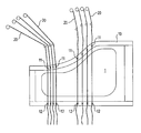
- FIGS. 1A-1E show schematic sectional views of an embodiment of a device according to the present teachings at various stages of a method according to the present teachings.
- FIG. 2 shows a schematic plan view of an embodiment of the device.
- FIG. 3 shows a schematic plan view of a further embodiment of the device.
- FIG. 4 shows a schematic plan view of a further embodiment of the device.
- FIG. 1A a frame 10 is shown in a schematic sectional view.
- yarns 20 which are supplied from yarn coils 21 , can be yieldably tensioned in a tensioning plane.
- Holding devices 11 , 12 are provided on the frame 10 .
- these holding devices 11 , 12 preferably are designed as grippers 11 , 12 , which hold the yarns 20 in a force-controlled (force-mediated) manner by clamping and thereby allow a force-controlled (force-mediated) slippage of the yarns.
- One yarn end 20 e is drawn from right to left in FIG.
- a reserve segment 20 r of the yarn is thus provided laterally outside the gripper 12 , which reserve segment 20 r has a length r.
- the drawing (pulling) of the yarn may be effected using a yarn-drawing (yarn-pulling) device that is not shown in FIG. 1 .
- the gripper 12 may be moved, as shown in FIG.
- FIG. 1A-B towards the yarn roll 21 , may grip the yarn 20 there proximal to the yarn end 20 e , and may then draw (pull) the yarn end 20 e to the position shown in FIG. 1B .
- a positive (convex) tool 1 and a negative (concave) tool 2 respectively having complementary projections 1 a , 1 b , 2 c and recesses 2 a , 2 b , 1 c are shown in FIG. 1 .
- FIG. 1 As can be clearly seen by comparing FIG.
- the yarns 20 which are first tensioned in the tensioning plane, are drawn out of the tensioning plane by movement of the positive tool 1 perpendicular thereto, and abut on the contour of the tool (workpiece carrier) 1 .
- the complementary projections 1 a , 1 b , 2 c and recesses 2 a , 2 b , 1 c form (shape) the preform, i.e. form (shape) the component in a manner similar to deep-drawing. Again, the necessary additional yarn length is supplied via the slip holders 11 , 12 .
- the yarns 20 are subsequently cut in the vicinity of the grippers 11 located on the sides of the yarn coils 21 (see FIG. 1E ). Optionally, they can be cut also on the other side, even though the excess yarn length, which is possibly still present there, is already lost (used up due to central portion of the yarns 20 being drawn out of the tensioning plane).
- the cutting direction is schematically shown by scissors.
- FIGS. 2 and 3 show alternate arrangements for applying fibers 20 to the frame 10 , wherein the yarns 20 are separately and individually held by each of the grippers 11 , 12 .
- FIG. 4 shows two layers of yarns 20 disposed on the frame 10 in different orientations.
Abstract
A method for manufacturing a fiber layer or a component perform includes yieldably tensioning a plurality of yarns in a tensioning plane such that each yarn is separately and individually held in a yieldable manner. Then, a workpiece carrier is moved through the tensioning plane in a perpendicular direction thereto such that the yarns contact the workpiece carrier and respectively bend according to the contour of the workpiece carrier. If a predetermined tensile force on one or more of the plurality of yarns is exceeded, then an additional length of such yarn(s) is supplied from a reserve and/or a coil to cover the workpiece carrier. Then, the ends of the yarns are fixed along an edge of the workpiece carrier.
Description
This application is the U.S. national stage of International Application No. PCT/EP2012/001422 filed on Mar. 30, 2012, which claims priority to German patent application no. 10 2011 100 640.4 filed on May 5, 2011.
The invention relates to methods and devices for manufacturing fiber layers and structural component preforms made of fibers, in particular using frames having elastic fiber tensioning.
Nowadays, components made of fiber composite materials are mostly manufactured from a plurality of layers of sheet-like semi-finished products such as fabrics or fiber layers. In this case, the layers can be dry (preform technology) or infiltrated with matrix resin (prepreg technology). In this case, the semi-finished products are manufactured from individual yarns comprised of reinforcing fibers, such as for example from rovings. For the manufacture of components, cut sheets are produced from such semi-finished products, which cut sheets are then—usually manually—laid on a positive mold or negative mold corresponding to the component geometry. The cut sheets are placed over the mold individually or in stacks and—often in a manual process—draped into the component mold. For complex shapes of components having a high deep-drawing ratio, cuts and overlappings in the semi-finished product are necessary, since the stretchability and shearability of the semi-finished products is limited.
Disadvantages of these methods are:
-
- Use of more expensive semi-finished products (value creation step, warehousing of various semi-finished products, cooling and expiration date for prepregs)
- Sheet cutting and between 30% and 70% waste (clippings)
- Difficult and quality-critical handling of flaccid individual cut sheets
- Shaping of semi-finished products is limited
- Many manual process steps
- Long processing time, high material costs, limited reproducibility
In one aspect of the present teachings, a device and a method for manufacturing fiber layers and component fiber preforms made of fibers are provided that at least partially overcome these disadvantages.
In one aspect of the present teachings, a method for manufacturing fiber layers and/or component preforms from fibers may preferably include:
-
- a) tensioning a plurality of yarns in a tensioning plane;
- b) moving a workpiece carrier through the tensioning plane in a direction substantially perpendicular to the tensioning plane;
- c) fixing the yarns on the workpiece carrier to form the fiber layer and/or the component preform.
Steps a) to c) optionally may be repeated one or more times. Preferably, the yarns are yieldably held at or proximal to the edge of the tensioning plane in steps a) and b).
In another aspect of the present teachings, a device for manufacturing fiber layers and/or component preforms from fibers may preferably include:
-
- a tensioning device configured to tension a plurality of yarns in a tensioning plane, the tensioning device including a holding device for yieldably holding the yarns in an individual manner,
- a workpiece carrier having a contour corresponding to the fiber layer to be manufactured and/or to the component preform, and
- a device configured to move the tensioning device relative to the workpiece carrier, or vice versa, such that the workpiece carrier is movable at least partially through the tensioning plane in a direction that is at least substantially perpendicular to the tensioning plane.
Preferably, the holding devices may be designed as grippers that yieldably hold the yarns at the edge of the tensioning plane by an elastic or force-controlled holding technique. In case the tensile force on any one or more of the yarns exceeds a predetermined tensile force, an additional length of yarn is supplied from a coil or reserve to the portion of the to-be-manufactured fiber layer or component perform that contacts, and is subsequently fixed to, the workpiece carrier.
Among other things, methods and devices are disclosed herein that enable the automated manufacture of dry preforms (preforms) and of preforms having integrated matrix material (prestacks, e.g. prepregs) for components made from fiber composite materials, which components may have a two-dimensional (planar) extension (2D), such as plates, or may have a three-dimensional (non-planar) extension (3D) with a complex geometry such as handles, body panels, etc. In the present specification, preforms are molded parts having geometries, which are similar to structural components and which are made from reinforcing yarns and optionally additives for the further processing. In this case, the preforms, i.e. both dry preforms and prestacks, can be packed in handling (shipping) bags made of foils, or plastic moldings.
For covering a flat or three-dimensional component mold, a plurality of yarns, preferably rovings, are held in a tensioning plane using a device for elastically tensioning the yarns, in particular using a frame having elastic yarn tensioning. The yarns are thus preferably elastically held laterally on both sides of the tensioning plane, wherein an additional (reserve) length of the yarn can subsequently be supplied on at least one side. The yarns extend in the tensioning plane, e.g. in the frame, in a straight-line manner from one side to the opposite side. The yarns can be made to completely cover the surface of the tensioning plane by laying the yarns adjacent to one another in the tensioning plane, i.e. for example in the frame.
A workpiece carrier in the shape of a molding tool (“positive tool”) having the geometry of the component or a suitable pre-geometry is pushed at least substantially perpendicularly through the tensioning plane, i.e. for example from above or below through the frame (or the tensioning plane or the frame moves over the tool, i.e. relative to each other). In this way, the yarns located in the tensioning plane (in the frame) are bent and tensioned over the tool mold. A second molding tool (“negative tool”) can assist, from the opposite direction, in shaping the fiber layer. The yarns are thus yieldably (i.e. for example elastically or using slippage or the like) held in the tensioning plane, i.e. for example in the tensioning frame. Consequently, in case additional yarn lengths are required due the movement of workpiece carrier relative to the tensioning plane (and the possible relative movement of the further molding tool), such additional yarn lengths can be supplied from the reserve length of the yarn provided at at least one edge of the workpiece carrier, so that the workpiece carrier is covered with appropriately tensioned yarns during the deep-drawing of 3D shapes. Thus, it is preferable that each yarn is separately yieldably held in an individual manner; even more preferably, the yarns are yieldably held on both lateral sides of the tensioning plane.
One or more tensioning planes can be utilized. A plurality of tensioning planes can preferably be realized by using one or more frames disposed one-over-the-other. A square or rectangular frame in plan view can hold e.g. one or two tensioning planes, each having fiber sets tensioned parallel to one another; a hexagonal frame can tension three such tensioning planes, etc. A plurality of tensioning planes can also be realized with a plurality of frames, which are disposed one-over-the-other in a direction substantially perpendicular to the tensioning planes. In this way, a plurality of yarn layers can be produced or deposited on the workpiece carrier, simultaneously and with an appropriate orientation of the yarns. The yarn orientations can thus be different in all frames, so that a cross pattern arises. By appropriately designing the frame or by using two auxiliary frames, the yarns of all layers can be brought into contact as necessary, so that upon removal and/or deep drawing, they behave as a single layer and e.g. can simultaneously be brought into contact with the positive tool.
The application of the yarns is thus effected such that only minimally more yarn lengths are yieldably held, i.e. for example in the frame, than are needed for covering the component mold (workpiece carrier).
For this purpose the frames are preferably matched to the component contour such that the holding points in each frame lie close to the component periphery. Alternatively, the holding points can be adjustable instead of the frame.
Tensioning and removal are preferably performed as follows. At the holding points on one lateral side of the tensioning plane, i.e. preferably a lateral frame side (introduction side), the yarns from yarn coils are introduced and held ready for use. The yarn ends are transported (e.g. drawn), e.g. using grippers, from a holding point on the introduction side to a holding point on the opposing lateral side of the tensioning plane, i.e. preferably the opposing lateral frame side (introduction side). On the target side, the holding point or the positioning of the (each) gripper is selected such that an individual yarn reserve (additional yarn length) is held ready for use. This yarn reserve preferably corresponds to the length of yarn that is drawn out of the tensioning plane (the frame plane) upon the matching to the contour of the component or workpiece carrier. Thus for example upon submerging the molding tool through the frame, the yarns on the introduction side can be redrawn directly from the coils, while on the target side the required additional yarn length can be drawn from this reserve.
After completing the molding process, the yarns are severed on the introduction side and are released from the holding points on the target side.
The layers shaped in one molding step are held in one of the two molding tools (e.g. using a vacuum, needles, adhesive materials, grippers, clamps, freeze grippers) and the two molding tools can be separated and return to their initial positions.
The term “yarns” herein generally indicates rovings or tows made from reinforcing fibers and matrix fibers or auxiliary fibers made from e.g. carbon, glass, aramid, basalt, or other materials. Wide tows (so-called heavy tows), foil strips or strips of auxiliary materials also can be processed (utilized) as yarns in accordance with the present teachings.
Variants and specific embodiments of the present teachings include:
-
- Covering of the tensioning plane (of the frame) over the entire surface or only partially (e.g. a strip only in the center or at the edges);
- Yieldable holding of the yarns at the edge(s) of the tensioning plane (frame edge)—elastically (spring, pneumatic) or force-controlled (slippage in clamping, guiding over a braked pulley, weight);
- Simultaneous or sequential application of the yarns in the tensioning plane(s) or on the frame(s);
- Positive tool can be solid, or elastic in parts, or multipart;
- Negative tool can be solid, or fully elastic or elastic in parts, or also multipart;
- Tool actuators can be mechanical or pneumatic or hydraulic. (Stamps, membranes . . . );
- The individual solid and elastic parts of positive and negative tools can be independently controlled and sequentially moved;
- The movement of positive and negative tools toward the tensioning plane or toward the frame can be effected in a straight-line manner or on curved paths, with and without additional rotation (e.g. rolling movement when submerging into the frame);
- Positive and negative tools can be heated and can exert pressure on the fiber layer (e.g. for compacting, activating of binders, and consolidating of the preform);
- Additional materials such as polymer yarns, polymer foils, and webs, can be used between the layers (e.g. analogously to the reinforcing fiber yarns), in order to assist the reshaping and cohesion of the preform (e.g. adhering or fusible yarns, foils, webs, resin films, thermoplastic yarns or foils or webs . . . );
- The reshaping can be assisted and controlled by inserting or laying-on (between or on the reinforcing fiber layers) special membranes, foils, or webs, wherein these membranes, foils, or webs have locally-adjustable stretchability and shearability;
- The grippers can move out (away) from the target side over the frame, grip (pick up) the yarn ends, and draw them (back) over the frame. The grippers thus move farther than to the end of the component contour, in order to produce the yarn reserve on the target side.
- The grippers can be individually moved;
- Alternatively, the two opposing holding points of a frame can move together (e.g. on a frame part) towards each other, grip all yarn ends, and tension the yarns over the frame in the subsequent movement of the holding points away from each other;
- Alternatively, the frame can itself be elastic, and thus provide the required yielding property when holding the yarns;
- Specific embodiment of the frame, the holding points, and the grippers;
- Multi-stage shaping (primary shaping→raw geometry;
- Secondary shaping→finished geometry) are possible; and
- The heating and/or compressing of the preform also serve(s) in particular to provide an intermediate fixing of the layers and/or an improved handling.
Advantages:
-
- Fast production times (automation, simultaneous applying of one or more entire layers, automatic shaping without intermediate handling/treatment);
- Low waste, thereby significant reduction of material costs;
- Direct production of components from fiber materials and, optionally, matrix materials and/or auxiliary materials; no semi-finished products necessary; thereby cost reductions in material procurement and warehousing;
- Any complex geometries are manufacturable, since there are no limitations with respect to shearing or stretching, which has been a problem for semi-finished products;
- High reproducibility due to automation.
Further advantages and useful characteristics follow from the description of exemplary embodiments referring to the Figures:
In FIG. 1A , a frame 10 is shown in a schematic sectional view. By using this frame 10, yarns 20, which are supplied from yarn coils 21, can be yieldably tensioned in a tensioning plane. Holding devices 11, 12 are provided on the frame 10. In the embodiment shown in FIG. 1 , these holding devices 11, 12 preferably are designed as grippers 11, 12, which hold the yarns 20 in a force-controlled (force-mediated) manner by clamping and thereby allow a force-controlled (force-mediated) slippage of the yarns. One yarn end 20 e is drawn from right to left in FIG. 1A from the right lateral side of the frame (tensioning plane) 10 to the opposite (left) side of the frame (tensioning plane) 10 and is held on the right in the gripper 11 and on the left in the gripper 12 (see FIG. 1B ). A reserve segment 20 r of the yarn is thus provided laterally outside the gripper 12, which reserve segment 20 r has a length r. The drawing (pulling) of the yarn may be effected using a yarn-drawing (yarn-pulling) device that is not shown in FIG. 1 . In the alternative, the gripper 12 may be moved, as shown in FIG. 1A-B , towards the yarn roll 21, may grip the yarn 20 there proximal to the yarn end 20 e, and may then draw (pull) the yarn end 20 e to the position shown in FIG. 1B . A positive (convex) tool 1 and a negative (concave) tool 2 respectively having complementary projections 1 a, 1 b, 2 c and recesses 2 a, 2 b, 1 c are shown in FIG. 1 . As can be clearly seen by comparing FIG. 1B to 1D , the yarns 20, which are first tensioned in the tensioning plane, are drawn out of the tensioning plane by movement of the positive tool 1 perpendicular thereto, and abut on the contour of the tool (workpiece carrier) 1. As can be clearly seen by comparing FIGS. 1B and 1C , a first part of the reserve length r is thus used as the yarns 20 are drawn through the slip holder (=gripper 12). Analogously, yarns 20 are guided back from the side of the yarn coil 21 through the slip holder (=gripper 11). When the negative mold 2 is lowered in the opposite direction, as shown in FIG. 1D , the complementary projections 1 a, 1 b, 2 c and recesses 2 a, 2 b, 1 c form (shape) the preform, i.e. form (shape) the component in a manner similar to deep-drawing. Again, the necessary additional yarn length is supplied via the slip holders 11, 12.
The yarns 20 are subsequently cut in the vicinity of the grippers 11 located on the sides of the yarn coils 21 (see FIG. 1E ). Optionally, they can be cut also on the other side, even though the excess yarn length, which is possibly still present there, is already lost (used up due to central portion of the yarns 20 being drawn out of the tensioning plane). The cutting direction is schematically shown by scissors.
The variants and specific embodiments described above in the Summary section can also be used in the described schematic (detailed) embodiment.
It is explicitly stated that all features disclosed in the description and/or the claims are intended to be disclosed separately and independently from one another for the purpose of original disclosure as well as for the purpose of restricting the claimed invention independent of the composition of the features in the embodiments and/or the claims. It is explicitly stated that all value ranges or indications of groups of entities disclose every possible intermediate value or intermediate entity for the purpose of original disclosure as well as for the purpose of restricting the claimed invention.
Claims (30)
1. A method for manufacturing a laid fiber fabric or a component preform, comprising:
(a) tensioning a first plurality of yarns in a first tensioning plane using a frame configured to yieldably tension the yarns such that each individual yarn is separately held in a yieldable manner;
(b) moving a workpiece carrier through the first tensioning plane in a direction that is at least substantially perpendicular to the first tensioning plane; and
(c) fixing the yarns on the workpiece carrier so as to form the laid fiber fabric or the component preform,
wherein each of the yarns is separately, individually and yieldably held at both first and second opposing lateral edges of the at least one tensioning plane such that, on at least one of the first and second edges, additional lengths of the first plurality of yarns are respectively supplyable, in an individual and independent manner, to cover the workpiece carrier during step (b).
2. The method according to claim 1 , wherein:
step (a) further comprises tensioning a second plurality of yarns in a second tensioning plane such that each of the second plurality of yarns is separately and individually held in a yieldable manner; and
in step (b) the workpiece carrier simultaneously moves through the first and second tensioning planes.
3. The method according to claim 2 , wherein the first tensioning plane is at least substantially parallel to the second tensioning plane.
4. The method according to claim 3 , further comprising (i) impregnating the yarns with a matrix resin to form a prepreg or (ii) inserting an additional material between the first plurality of yarns and the second plurality of yarns, the additional material being selected from the group consisting of polymer yarns, polymer foils and polymer webs.
5. The method according to claim 3 , wherein each of the first and second plurality of yarns comprises at least one roving or at least one tow comprised of a plurality of fibers.
6. The method according to claim 5 , wherein in step (b) the additional lengths of the first and second plurality of yarns are respectively supplied from respective yarn coils and/or from respective yarn reserves to cover the workpiece carrier when a predetermined tensile force is exceeded on one or more of the first and second plurality of yarns.
7. The method according to claim 1 , wherein:
step (a) further comprises tensioning a second plurality of yarns in a second tensioning plane such that each of the second plurality of yarns is separately and individually held in a yieldable manner; and
in step (b) the workpiece carrier simultaneously moves through the first and second tensioning planes.
8. The method according to claim 1 , further comprising (i) impregnating the yarns with a matrix resin to form a prepreg or (ii) disposing an additional material on the first plurality of yarns, the additional material being selected from the group consisting of polymer yarns, polymer foils and polymer webs.
9. The method according to claim 1 , wherein each of the yarns comprises a roving or tow comprised of a plurality of fibers.
10. A device for manufacturing a laid fiber fabric or a component preform, comprising:
a first tensioning device configured to tension a first plurality of yarns in a first tensioning plane using a first frame configured to separately hold and tension each individual yarn, the frame including a first plurality of holding devices configured to separately and yieldably hold the respective yarns of the first plurality of yarns, and
a workpiece carrier having a contour corresponding to the laid fiber fabric or the component preform to be manufactured, wherein the workpiece carrier is configured to be movable relative to the tensioning device such that (i) the workpiece carrier is movable at least partially through the first tensioning plane in a direction at least substantially perpendicular to the first tensioning plane and (ii) the first plurality of yarns contacts the workpiece carrier and bends according to the contour of the workpiece carrier,
wherein the device is configured to separately, individually and yieldably hold each of the first plurality of yarns at both first and second opposing lateral edges of the at least one tensioning plane such that, on at least one of the first and second edges, additional lengths of the plurality of yarns are respectively supplyable in an individual and independent manner.
11. The device according to claim 10 , wherein the first plurality of holding devices comprises a first plurality of individually-operable grippers respectively configured to individually and yieldably hold the respective yarns of the first plurality of yarns at an edge of the first tensioning plane by an elastic or force-controlled retention.
12. The device according to claim 11 , further comprising:
a second tensioning device configured to tension a second plurality of yarns in a second tensioning plane and including a second plurality of holding devices configured to separately, individually and yieldably hold the respective yarns of the second plurality of yarns, the second tensioning plane being at least substantially parallel to the first tensioning plane.
13. The device according to claim 12 , wherein the first plurality of yarns extends in a direction that is oblique or perpendicular to the second plurality of yarns.
14. The device according to claim 13 , wherein the first and second plurality of holding devices each respectively comprise at least one device selected from the group consisting of a spring, a pneumatic device, a clamp, a braked guide pulley and a weight, wherein the clamp is configured to permit slippage of the respective yarn therethrough when a predetermined tensile force on the yarn is exceeded.
15. The device according to claim 10 , further comprising:
a second tensioning device configured to tension a second plurality of yarns in a second tensioning plane and including a second plurality of holding devices configured to separately, individually and yieldably hold the respective yarns of the second plurality of yarns, the second tensioning plane being at least substantially parallel to the first tensioning plane,
wherein the first plurality of yarns extends in a direction that is oblique or perpendicular to the second plurality of yarns.
16. The device according to claim 10 , wherein the first plurality of holding devices respectively comprises a plurality of clamps each configured to permit individual slippage of the respective yarn therethrough when a predetermined tensile force on the respective yarn is exceeded.
17. The device according to claim 10 , wherein the first plurality of holding devices comprises a first plurality of individually-operable grippers.
18. A method for manufacturing a laid fiber fabric or a component preform, comprising:
(a) pulling a plurality of yarns from a plurality of yarn coils across a frame and yieldably and respectively fixing the individual yarns of the plurality of yarns under tension in a first tensioning plane in a plurality of individually-operable and individually-movable grippers disposed along at least one edge of the frame, wherein a reserve length of the yarns is maintained on the at least one edge of the frame,
(b) deep-drawing the plurality of yarns by moving a tool mold, which has a contour that is at least partially convex, through the first tensioning plane in a direction that is at least substantially perpendicular to the first tensioning plane such that the plurality of yarns contacts the tool mold and bends according to the contour of the tool mold, wherein when a predetermined tensile force on any one or more of the grippers is exceeded, at least a portion of the reserve length of the respective yarn slips through the respective gripper and is supplied to cover the workpiece carrier, and
(c) severing or releasing the yarns along an edge of the tool mold so as to form the laid fiber fabric or the component preform.
19. The method according to claim 18 , wherein each of the yarns are separately and yieldably held at first and second opposing lateral edges of the first tensioning plane such that, on at least one of the first and second edges, additional lengths of the plurality of yarns are respectively supplyable to cover the tool mold during step (b).
20. The method according to claim 19 , wherein each yarn is separately, individually and yieldably held on both the first and second opposing lateral edges of the first tensioning plane.
21. The method according to claim 20 , wherein:
step (a) further comprises tensioning a second plurality of yarns in a second tensioning plane such that each of the second plurality of yarns is separately and individually held in a yieldable manner; and
in step (b) the tool mold simultaneously moves through the first and second tensioning planes.
22. The method according to claim 21 , wherein the first tensioning plane is at least substantially parallel to the second tensioning plane.
23. The method according to claim 22 , further comprising (i) impregnating the yarns with a matrix resin to form a prepreg or (ii) inserting an additional material between the first plurality of yarns and the second plurality of yarns, the additional material being selected from the group consisting of polymer yarns, polymer foils and polymer webs.
24. The method according to claim 22 , wherein each of the first and second plurality of yarns comprises at least one roving or at least one tow comprised of a plurality of fibers.
25. The method according to claim 24 , wherein in step (b) the additional lengths of the first and second plurality of yarns are respectively supplied from respective yarn coils or from respective yarn reserves to cover the tool mold when a predetermined tensile force is exceeded on one or more of the first and second plurality of yarns.
26. The method according to claim 18 , wherein:
step (a) further comprises tensioning a second plurality of yarns in a second tensioning plane such that each of the second plurality of yarns is separately and individually held in a yieldable manner; and
in step (b) the tool mold simultaneously moves through the first and second tensioning planes.
27. The method according to claim 26 , wherein in step (b) the additional lengths of the first and second plurality of yarns are respectively and individually supplied from respective yarn coils or from respective yarn reserves to cover the tool mold when a predetermined tensile force is exceeded the respective yarn or yarns.
28. The method according to claim 18 , further comprising (i) impregnating the yarns with a matrix resin to form a prepreg or (ii) disposing an additional material on the first plurality of yarns, the additional material being selected from the group consisting of polymer yarns, polymer foils and polymer webs.
29. The method according to claim 1 , wherein:
in step (a), each of the first plurality of yarns is individually pulled and is yieldably and separately held by one of a plurality of grippers,
in step (b) the additional lengths of the first plurality of yarns are respectively and individually supplied from respective yarn coils or from respective yarn reserves to cover the workpiece carrier when a predetermined tensile force on one or more of the grippers is exceeded such that the additional lengths slip through the respective grippers that are subjected to the predetermined tensile force or higher and no additional lengths are supplied through ones of the grippers that are subjected to a force less than the predetermined tensile force, and
after step (c), the yarns are severed or released along an edge of the workpiece carrier so as to form the laid fiber fabric or the component preform.
30. The device according to claim 10 , wherein:
the first plurality of holding devices respectively comprises a plurality of individually-operable grippers each configured to individually pull the respective yarns to cover the workpiece carrier and to permit slippage of the respective yarns therethrough when a predetermined tensile force on the respective gripper is exceeded and to prevent slippage of the respective yarns therethrough when the predetermined tensile force on the respective gripper is not exceeded; and
the device is configured to severe or release the yarns along an edge of the workpiece carrier after the yarns have been bent into the contour corresponding to the laid fiber fabric or the component preform to be manufactured.
Applications Claiming Priority (4)
| Application Number | Priority Date | Filing Date | Title |
|---|---|---|---|
| DE102011100640.4 | 2011-05-05 | ||
| DE102011100640 | 2011-05-05 | ||
| DE102011100640A DE102011100640A1 (en) | 2011-05-05 | 2011-05-05 | Method and apparatus for making fiber webs and component preforms from fibers |
| PCT/EP2012/001422 WO2012149990A1 (en) | 2011-05-05 | 2012-03-30 | Method and apparatus for producing laid fibre fabrics and component preforms made of fibres |
Publications (2)
| Publication Number | Publication Date |
|---|---|
| US20140103571A1 US20140103571A1 (en) | 2014-04-17 |
| US9718233B2 true US9718233B2 (en) | 2017-08-01 |
Family
ID=45953065
Family Applications (1)
| Application Number | Title | Priority Date | Filing Date |
|---|---|---|---|
| US14/115,552 Active 2033-12-29 US9718233B2 (en) | 2011-05-05 | 2012-03-30 | Method and apparatus for producing laid fibre fabrics and component preforms made of fibres |
Country Status (5)
| Country | Link |
|---|---|
| US (1) | US9718233B2 (en) |
| EP (1) | EP2704887B1 (en) |
| DE (1) | DE102011100640A1 (en) |
| PL (1) | PL2704887T3 (en) |
| WO (1) | WO2012149990A1 (en) |
Cited By (3)
| Publication number | Priority date | Publication date | Assignee | Title |
|---|---|---|---|---|
| US10137647B2 (en) * | 2012-12-28 | 2018-11-27 | Compositence Gmbh | Method and device for manufacturing three-dimensional fiber fabrics and component preforms made of fibres in two steps |
| WO2020219889A1 (en) * | 2019-04-24 | 2020-10-29 | Arris Composites Inc. | Method and system for batch preforming of fiber bundles |
| US11007729B2 (en) * | 2013-04-24 | 2021-05-18 | Airbus Defence and Space GmbH | Laying die, laying device and method for manufacturing a laying die |
Families Citing this family (10)
| Publication number | Priority date | Publication date | Assignee | Title |
|---|---|---|---|---|
| DE102010015199B9 (en) | 2010-04-16 | 2013-08-01 | Compositence Gmbh | Fiber guiding device and apparatus for constructing a three-dimensional preform |
| DE102012007439A1 (en) | 2012-04-13 | 2013-10-17 | Compositence Gmbh | Laying head and apparatus and method for building a three-dimensional preform for a component made of a fiber composite material |
| EP2874800B1 (en) * | 2012-07-18 | 2016-09-14 | Voith Patent GmbH | Device and method for producing fibre-reinforced plastics components |
| WO2018156521A1 (en) * | 2017-02-21 | 2018-08-30 | Seriforge, Inc. | Systems and methods of converting fiber into shaped fabric plies for composite preforms and products |
| DE102017205792A1 (en) * | 2017-04-05 | 2018-10-11 | Premium Aerotec Gmbh | Semi-finished product, process and consolidation tool for producing a thermoplastic fiber composite component |
| DE102018208009A1 (en) * | 2018-05-22 | 2019-11-28 | Ubc Composites Gmbh | Process for producing a fiber-reinforced component and device for carrying out the process |
| ES2734598B2 (en) * | 2018-10-10 | 2020-05-04 | Univ Madrid Politecnica | Machine for adapting a fiber structure to a mold for the manufacture of composite material parts |
| JP7153548B2 (en) * | 2018-12-10 | 2022-10-14 | 三菱重工業株式会社 | LAMINATED FORMING METHOD AND FORMING JIG |
| JP7317154B2 (en) * | 2020-02-10 | 2023-07-28 | 三菱重工業株式会社 | Molding jig and molding method |
| GB2607073B (en) * | 2021-05-27 | 2024-03-06 | Gkn Aerospace Services Ltd | Non-crimp fibre forming |
Citations (36)
| Publication number | Priority date | Publication date | Assignee | Title |
|---|---|---|---|---|
| US2964442A (en) * | 1956-08-22 | 1960-12-13 | Polyplex Danish American Plast | Methods of molding reinforced organic plastics for the production of curved plates |
| US3115678A (en) * | 1960-10-07 | 1963-12-31 | Collins & Aikman Corp | Apparatus for molding plastic carpets |
| DE3003666A1 (en) | 1980-02-01 | 1981-08-06 | Richard 4937 Lage Pott | Mechanically laying reinforcements for laminated components - using machine which winds unidirectional layers of filaments for subsequent bonding and cure |
| DE3027655A1 (en) | 1980-03-17 | 1981-09-24 | Herbert 7140 Ludwigsburg Schreiber | METHOD FOR PRODUCING FIBER REINFORCED PLASTIC OBJECTS |
| US4432716A (en) | 1981-03-20 | 1984-02-21 | Lignotock Verfahrenstechnik Gmbh | Apparatus for moulding three-dimensionally shaped moulded articles from binder-containing web-like non-woven fabrics |
| EP0415870A2 (en) | 1989-08-28 | 1991-03-06 | United Technologies Corporation | Preform liners for resin transfer molding |
| JPH03287824A (en) | 1990-03-30 | 1991-12-18 | Toray Ind Inc | Crimping apparatus and production of crimped linear body |
| DE4115831A1 (en) | 1991-05-15 | 1992-11-19 | Bayer Ag | Prodn. of composite laminates - by laying together stack of reinforcing fibrous, materials and thermoplastics, enclosing in film tubing, exhausting tubing and hot pressing |
| US5344687A (en) | 1991-09-27 | 1994-09-06 | Brunswick Technologies, Inc. | Structurally reinforced thermoplastic-fabric composite construction materials that are moldable |
| EP0626252A1 (en) | 1993-05-26 | 1994-11-30 | AEROSPATIALE Société Nationale Industrielle | Machine for contact winding a plurality of individual yarns simultaneously |
| US6054003A (en) * | 1997-06-10 | 2000-04-25 | Bak; Henning | Method of producing a fiber-reinforced, three-dimensional product |
| DE10005202A1 (en) | 2000-02-03 | 2000-11-02 | Inst Verbundwerkstoffe Gmbh | Fiber reinforcement preforms oriented for particular applications are assembled by securing fiber bundles into place by stitching |
| DE19922799A1 (en) | 1999-05-18 | 2000-11-23 | Bayerische Motoren Werke Ag | Composite plastic molding e.g. for vehicle floor pan, involves preforming tool to shape reinforcing fabric before placing it in molding tool |
| US6585842B1 (en) | 1997-03-28 | 2003-07-01 | Societe Nationale D'etude Et De Construction De Moteurs D'aviation (Snecma) | Method and machine for producing multiaxial fibrous webs |
| US20030133691A1 (en) * | 2002-01-11 | 2003-07-17 | Levert Joseph A. | Tension-assisted mounting of fibers on a substrate |
| WO2003099545A1 (en) | 2002-05-29 | 2003-12-04 | Societe De Technologie Michelin | Device and method for applying a strip to a rotary surface |
| DE10250826A1 (en) | 2002-10-31 | 2004-05-19 | Fraunhofer-Gesellschaft zur Förderung der angewandten Forschung e.V. | Process for the production of a 3-dimensional preform |
| EP1584462A2 (en) | 2004-03-23 | 2005-10-12 | Alenia Aeronautica S.P.A. | A method for the manufacture of a dry reinforcing preform for a composite structural member of an aircraft |
| EP1724098A1 (en) | 2005-05-20 | 2006-11-22 | Carbo Tech Composites GmbH | Process for the production of a laminated composite product and a composite product made by the lamination process |
| WO2008056980A2 (en) | 2006-11-07 | 2008-05-15 | N-Tex Technologies B.V. | Method and device for reducing the differences between the tensile stresses in flexible elements |
| GB2452298A (en) | 2007-08-30 | 2009-03-04 | Gkn Aerospace Services Ltd | Composite structure with a hollow body and a rim |
| WO2009077581A2 (en) | 2007-12-19 | 2009-06-25 | Vestas Wind Systems A/S | An apparatus for preparing a pre-form |
| US20090229760A1 (en) | 2005-03-03 | 2009-09-17 | Alexander Hamlyn | Fiber application machine |
| WO2009124724A1 (en) | 2008-04-07 | 2009-10-15 | Airbus Operations Gmbh | Method for the production of a fiber composite/fiber-reinforced plastic part from rovings by means of a mold, and mold for carrying out said method |
| DE102008019147A1 (en) | 2008-04-16 | 2009-10-22 | Airbus Deutschland Gmbh | Process for the production of fiber preforms |
| WO2009158262A1 (en) | 2008-06-27 | 2009-12-30 | Union Carbide Chemicals & Plastics Technology Llc | Pultrusion process for the manufacture of fiber reinforced composites |
| EP2159310A1 (en) | 2007-05-21 | 2010-03-03 | Kabushiki Kaisha Toyoda Jidoshokki | Fiber bundle arranging device and fiber bundle arranging method |
| US20100126652A1 (en) | 2005-07-22 | 2010-05-27 | Paul Joern | Method for producing single-or multi-layered fiber preforms by the tfp process |
| US20110083605A1 (en) | 2009-10-08 | 2011-04-14 | General Electric Company | Resin application and infusion system |
| WO2011128110A1 (en) | 2010-04-16 | 2011-10-20 | Compositence Gmbh | Device and method for producing laid fibre fabrics |
| WO2012035105A1 (en) | 2010-09-17 | 2012-03-22 | Airbus Operations Gmbh | A method and a device for the preparation of a dry textile preform |
| EP2433784A1 (en) | 2010-09-24 | 2012-03-28 | General Electric Company | System and method for the automated delivery and layup of resin infused fibers |
| WO2012136394A1 (en) | 2011-04-08 | 2012-10-11 | Voith Patent Gmbh | Device and method for producing fiber preforms, which are a precursor in the production of fiber-reinforced plastic components in particular |
| WO2012136393A1 (en) | 2011-04-08 | 2012-10-11 | Voith Patent Gmbh | Device and method for producing fiber preforms, which are a precursor in the production of fiber-reinforced plastic components in particular |
| WO2012136392A1 (en) | 2011-04-08 | 2012-10-11 | Voith Patent Gmbh | Device and method for producing fiber preforms, which are a precursor in the production of fiber-reinforced plastic components in particular |
| WO2012136391A1 (en) | 2011-04-08 | 2012-10-11 | Voith Patent Gmbh | Device and method for producing fiber preforms, which are a precursor in the production of fiber-reinforced plastic components in particular |
-
2011
- 2011-05-05 DE DE102011100640A patent/DE102011100640A1/en not_active Withdrawn
-
2012
- 2012-03-30 EP EP12713881.6A patent/EP2704887B1/en not_active Not-in-force
- 2012-03-30 PL PL12713881T patent/PL2704887T3/en unknown
- 2012-03-30 WO PCT/EP2012/001422 patent/WO2012149990A1/en active Application Filing
- 2012-03-30 US US14/115,552 patent/US9718233B2/en active Active
Patent Citations (61)
| Publication number | Priority date | Publication date | Assignee | Title |
|---|---|---|---|---|
| US2964442A (en) * | 1956-08-22 | 1960-12-13 | Polyplex Danish American Plast | Methods of molding reinforced organic plastics for the production of curved plates |
| US3115678A (en) * | 1960-10-07 | 1963-12-31 | Collins & Aikman Corp | Apparatus for molding plastic carpets |
| DE3003666A1 (en) | 1980-02-01 | 1981-08-06 | Richard 4937 Lage Pott | Mechanically laying reinforcements for laminated components - using machine which winds unidirectional layers of filaments for subsequent bonding and cure |
| DE3027655A1 (en) | 1980-03-17 | 1981-09-24 | Herbert 7140 Ludwigsburg Schreiber | METHOD FOR PRODUCING FIBER REINFORCED PLASTIC OBJECTS |
| US4432716A (en) | 1981-03-20 | 1984-02-21 | Lignotock Verfahrenstechnik Gmbh | Apparatus for moulding three-dimensionally shaped moulded articles from binder-containing web-like non-woven fabrics |
| EP0415870A2 (en) | 1989-08-28 | 1991-03-06 | United Technologies Corporation | Preform liners for resin transfer molding |
| US5134002A (en) | 1989-08-28 | 1992-07-28 | United Technologies Corporation | Mold liners for resin transfer molding |
| JPH03287824A (en) | 1990-03-30 | 1991-12-18 | Toray Ind Inc | Crimping apparatus and production of crimped linear body |
| DE4115831A1 (en) | 1991-05-15 | 1992-11-19 | Bayer Ag | Prodn. of composite laminates - by laying together stack of reinforcing fibrous, materials and thermoplastics, enclosing in film tubing, exhausting tubing and hot pressing |
| US5344687A (en) | 1991-09-27 | 1994-09-06 | Brunswick Technologies, Inc. | Structurally reinforced thermoplastic-fabric composite construction materials that are moldable |
| EP0626252A1 (en) | 1993-05-26 | 1994-11-30 | AEROSPATIALE Société Nationale Industrielle | Machine for contact winding a plurality of individual yarns simultaneously |
| US5645677A (en) | 1993-05-26 | 1997-07-08 | Societe Anonyme Dite Aerospatiale Societe Nationale Industrielle | Machine for the simultaneous laying down and winding of a plurality of individual fiber rovings |
| US6585842B1 (en) | 1997-03-28 | 2003-07-01 | Societe Nationale D'etude Et De Construction De Moteurs D'aviation (Snecma) | Method and machine for producing multiaxial fibrous webs |
| US6054003A (en) * | 1997-06-10 | 2000-04-25 | Bak; Henning | Method of producing a fiber-reinforced, three-dimensional product |
| DE19922799A1 (en) | 1999-05-18 | 2000-11-23 | Bayerische Motoren Werke Ag | Composite plastic molding e.g. for vehicle floor pan, involves preforming tool to shape reinforcing fabric before placing it in molding tool |
| DE10005202A1 (en) | 2000-02-03 | 2000-11-02 | Inst Verbundwerkstoffe Gmbh | Fiber reinforcement preforms oriented for particular applications are assembled by securing fiber bundles into place by stitching |
| US20030133691A1 (en) * | 2002-01-11 | 2003-07-17 | Levert Joseph A. | Tension-assisted mounting of fibers on a substrate |
| WO2003099545A1 (en) | 2002-05-29 | 2003-12-04 | Societe De Technologie Michelin | Device and method for applying a strip to a rotary surface |
| US20050139324A1 (en) | 2002-05-29 | 2005-06-30 | Michelin Recherche Et Technique S.A. | Apparatus for applying a strip to a rotary surface |
| DE10250826A1 (en) | 2002-10-31 | 2004-05-19 | Fraunhofer-Gesellschaft zur Förderung der angewandten Forschung e.V. | Process for the production of a 3-dimensional preform |
| US20060169396A1 (en) | 2002-10-31 | 2006-08-03 | Paul Joern | Method for producing a three-dimensional preform |
| US20050268832A1 (en) | 2004-03-23 | 2005-12-08 | Alenia Aeronautica S.P.A. | Method for the manufacture of a dry reinforcing preform for a composite structural member of an aircraft |
| EP1584462A2 (en) | 2004-03-23 | 2005-10-12 | Alenia Aeronautica S.P.A. | A method for the manufacture of a dry reinforcing preform for a composite structural member of an aircraft |
| US20090229760A1 (en) | 2005-03-03 | 2009-09-17 | Alexander Hamlyn | Fiber application machine |
| EP1724098A1 (en) | 2005-05-20 | 2006-11-22 | Carbo Tech Composites GmbH | Process for the production of a laminated composite product and a composite product made by the lamination process |
| US20090202789A1 (en) | 2005-05-20 | 2009-08-13 | Karl Wagner | Process for the Production of a Laminated Composite Product and a Composite Product made by the Lamination Process |
| CN101304859B (en) | 2005-07-22 | 2012-04-04 | 空中客车德国运营有限责任公司 | Method for producing one-or multi-layer layer fibre preforms according to a tfp method |
| US20100126652A1 (en) | 2005-07-22 | 2010-05-27 | Paul Joern | Method for producing single-or multi-layered fiber preforms by the tfp process |
| WO2008056980A2 (en) | 2006-11-07 | 2008-05-15 | N-Tex Technologies B.V. | Method and device for reducing the differences between the tensile stresses in flexible elements |
| CN101657575B (en) | 2007-05-21 | 2012-08-22 | 株式会社丰田自动织机 | Fiber bundle arranging device and fiber bundle arranging method |
| EP2159310A1 (en) | 2007-05-21 | 2010-03-03 | Kabushiki Kaisha Toyoda Jidoshokki | Fiber bundle arranging device and fiber bundle arranging method |
| US20100170628A1 (en) | 2007-05-21 | 2010-07-08 | Kabushiki Kaisha Toyota Jidoshokki | Fiber bundle arranging device and fiber bundle arranging method |
| US20100206994A1 (en) | 2007-08-30 | 2010-08-19 | Scott Barber | Composite structure and related method to obtain it |
| GB2452298A (en) | 2007-08-30 | 2009-03-04 | Gkn Aerospace Services Ltd | Composite structure with a hollow body and a rim |
| US8580060B2 (en) | 2007-12-19 | 2013-11-12 | Vestas Wind Systems A/S | Apparatus for preparing a pre-form |
| WO2009077581A2 (en) | 2007-12-19 | 2009-06-25 | Vestas Wind Systems A/S | An apparatus for preparing a pre-form |
| US20110000608A1 (en) | 2007-12-19 | 2011-01-06 | Vestas Wind Systems A/S | Apparatus for preparing a pre-form |
| WO2009124724A1 (en) | 2008-04-07 | 2009-10-15 | Airbus Operations Gmbh | Method for the production of a fiber composite/fiber-reinforced plastic part from rovings by means of a mold, and mold for carrying out said method |
| US20110115124A1 (en) | 2008-04-07 | 2011-05-19 | Airbus Operations Gmbh | Method For Manufacturing A FRC/FRP- Component From Rovings With A Moulding Tool And Moulding Tool For Implementing The Method |
| DE102008019147A1 (en) | 2008-04-16 | 2009-10-22 | Airbus Deutschland Gmbh | Process for the production of fiber preforms |
| US20110148007A1 (en) | 2008-04-16 | 2011-06-23 | Joachim Piepenbrock | Process for producing fibre preforms |
| WO2009127456A1 (en) | 2008-04-16 | 2009-10-22 | Airbus Operations Gmbh | Process for producing fibre preforms |
| WO2009158262A1 (en) | 2008-06-27 | 2009-12-30 | Union Carbide Chemicals & Plastics Technology Llc | Pultrusion process for the manufacture of fiber reinforced composites |
| US20110104364A1 (en) | 2008-06-27 | 2011-05-05 | Buo Chen | High-Speed Pultrusion Process for the Manufacture of Fiber Reinforced Composites |
| EP2314435A2 (en) | 2009-10-08 | 2011-04-27 | General Electric Company | Resin application and infusion system |
| US20110083605A1 (en) | 2009-10-08 | 2011-04-14 | General Electric Company | Resin application and infusion system |
| WO2011128110A1 (en) | 2010-04-16 | 2011-10-20 | Compositence Gmbh | Device and method for producing laid fibre fabrics |
| DE102010015199A1 (en) | 2010-04-16 | 2011-10-20 | Ingo Karb | Apparatus and method for making fibrous webs and component preforms from fibers |
| US20130174969A1 (en) | 2010-04-16 | 2013-07-11 | Compositence Gmbh | Apparatus and Method for Manufacturing Fibre Layers |
| US20130175723A1 (en) | 2010-09-17 | 2013-07-11 | Christian Luebbering | method and a device for the preparation of a dry textile preform |
| WO2012035105A1 (en) | 2010-09-17 | 2012-03-22 | Airbus Operations Gmbh | A method and a device for the preparation of a dry textile preform |
| US20120247651A1 (en) | 2010-09-24 | 2012-10-04 | General Electric Company | System and Method for the Automated Delivery and Layup of Resin Infused Fibers |
| US20120073730A1 (en) | 2010-09-24 | 2012-03-29 | General Electric Company | System and Method for the Automated Delivery and Layup of Resin Infused Fibers |
| EP2433784A1 (en) | 2010-09-24 | 2012-03-28 | General Electric Company | System and method for the automated delivery and layup of resin infused fibers |
| WO2012136394A1 (en) | 2011-04-08 | 2012-10-11 | Voith Patent Gmbh | Device and method for producing fiber preforms, which are a precursor in the production of fiber-reinforced plastic components in particular |
| WO2012136393A1 (en) | 2011-04-08 | 2012-10-11 | Voith Patent Gmbh | Device and method for producing fiber preforms, which are a precursor in the production of fiber-reinforced plastic components in particular |
| WO2012136392A1 (en) | 2011-04-08 | 2012-10-11 | Voith Patent Gmbh | Device and method for producing fiber preforms, which are a precursor in the production of fiber-reinforced plastic components in particular |
| WO2012136391A1 (en) | 2011-04-08 | 2012-10-11 | Voith Patent Gmbh | Device and method for producing fiber preforms, which are a precursor in the production of fiber-reinforced plastic components in particular |
| US20140035195A1 (en) | 2011-04-08 | 2014-02-06 | Voith Patent Gmbh | Device and method for producing fiber preforms |
| US20140041795A1 (en) | 2011-04-08 | 2014-02-13 | Voith Patent Gmbh | Device and method for producing fiber preforms |
| US20140131914A1 (en) | 2011-04-08 | 2014-05-15 | Voith Patent Gmbh | Device and method for producing fiber preforms |
Non-Patent Citations (6)
| Title |
|---|
| Communication mailed Feb. 10, 2015 from EPO in related EP application No. 12 713 881.6, including English translation of substantive portions. |
| Communication mailed Jul. 10, 2014 from EPO in related EP application No. 12 713 881.6, including English translation of substantive portions. |
| English translation of International Search Report for parent PCT application No. PCT/EP2012/001422. |
| English translation of Written Opinion for parent PCT application No. PCT/EP2012/001422. |
| Office Action mailed Apr. 2, 2015 in related U.S. Appl. No. 13/641,247. |
| Unpublished U.S. Appl. No. 14/394,182. |
Cited By (5)
| Publication number | Priority date | Publication date | Assignee | Title |
|---|---|---|---|---|
| US10137647B2 (en) * | 2012-12-28 | 2018-11-27 | Compositence Gmbh | Method and device for manufacturing three-dimensional fiber fabrics and component preforms made of fibres in two steps |
| US11007729B2 (en) * | 2013-04-24 | 2021-05-18 | Airbus Defence and Space GmbH | Laying die, laying device and method for manufacturing a laying die |
| WO2020219889A1 (en) * | 2019-04-24 | 2020-10-29 | Arris Composites Inc. | Method and system for batch preforming of fiber bundles |
| CN113891793A (en) * | 2019-04-24 | 2022-01-04 | 阿里斯复合材料有限公司 | Method and system for batch preforming of fiber bundles |
| US11345061B2 (en) | 2019-04-24 | 2022-05-31 | Arris Composites Inc. | Method and system for batch preforming of fiber bundles |
Also Published As
| Publication number | Publication date |
|---|---|
| US20140103571A1 (en) | 2014-04-17 |
| EP2704887A1 (en) | 2014-03-12 |
| EP2704887B1 (en) | 2017-02-15 |
| PL2704887T3 (en) | 2017-08-31 |
| WO2012149990A1 (en) | 2012-11-08 |
| DE102011100640A1 (en) | 2012-11-08 |
Similar Documents
| Publication | Publication Date | Title |
|---|---|---|
| US9718233B2 (en) | Method and apparatus for producing laid fibre fabrics and component preforms made of fibres | |
| KR101845453B1 (en) | Device and method for producing laid fibre fabrics | |
| RU2508199C2 (en) | Method of semi-finished product fabrication from esm laminate with two prepreg layers and process unit to this end | |
| JP5668874B2 (en) | Preform manufacturing method and fiber reinforced resin molded product manufacturing method | |
| JP5905082B2 (en) | Method and apparatus for conveying a fiber contour cut from a planar fiber fabric in the process of manufacturing a fiber reinforced plastic molded product | |
| US6592795B2 (en) | Continuous forming method and device for H-shaped FRP member | |
| KR101630584B1 (en) | Manufacturing method for article molded from fiber-reinforced composite material, and article molded from fiber-reinforced composite material | |
| JP6048730B2 (en) | Preform manufacturing method | |
| JP2014510178A5 (en) | ||
| EP2874800B1 (en) | Device and method for producing fibre-reinforced plastics components | |
| MX2014008643A (en) | Method and device for producing a three-dimensional preform from a fibre fabric as part of production of fibre-reinforced formed components. | |
| EP3597412A1 (en) | Shaping device for fiber material and shaping method for fiber material | |
| WO2020138473A1 (en) | Method for manufacturing preform, method for manufacturing composite material molded article, and mold | |
| EP2471649B1 (en) | Membrane manipulating and compacting device for the automated manufacture of composite preforms, and method for obtaining such preforms | |
| EP2186627B1 (en) | Method for continuously forming composite material shape member having varied cross-sectional shape | |
| US20140077423A1 (en) | Method and device for inserting cores of rovings into a press | |
| JP2020040402A (en) | Method for manufacturing curved omega stringers and z-shaped stringers of composite material, and method for manufacturing composite material stiffened panel with curvature | |
| US11660785B2 (en) | Method for manufacturing fiber-reinforced plastic | |
| US20220204182A1 (en) | Process for producing a component having a thermoplastic fiber composite and components made by the process | |
| JP2934437B1 (en) | Molding method of fiber reinforced composite material | |
| US20210402674A1 (en) | Composite material and method of forming composite material | |
| CN115023339A (en) | Automated mechanical forming of composite materials |
Legal Events
| Date | Code | Title | Description |
|---|---|---|---|
| AS | Assignment |
Owner name: COMPOSITENCE GMBH, GERMANY Free format text: ASSIGNMENT OF ASSIGNORS INTEREST;ASSIGNORS:KARB, INGO;WITZEL, VOLKER;SIGNING DATES FROM 20131025 TO 20131028;REEL/FRAME:031573/0583 |
|
| STCF | Information on status: patent grant |
Free format text: PATENTED CASE |
|
| MAFP | Maintenance fee payment |
Free format text: PAYMENT OF MAINTENANCE FEE, 4TH YR, SMALL ENTITY (ORIGINAL EVENT CODE: M2551); ENTITY STATUS OF PATENT OWNER: SMALL ENTITY Year of fee payment: 4 |