US9700841B2 - Synergized PGM close-coupled catalysts for TWC applications - Google Patents
Synergized PGM close-coupled catalysts for TWC applications Download PDFInfo
- Publication number
- US9700841B2 US9700841B2 US14/657,842 US201514657842A US9700841B2 US 9700841 B2 US9700841 B2 US 9700841B2 US 201514657842 A US201514657842 A US 201514657842A US 9700841 B2 US9700841 B2 US 9700841B2
- Authority
- US
- United States
- Prior art keywords
- pgm
- ccc
- spgm
- catalyst
- catalytic
- Prior art date
- Legal status (The legal status is an assumption and is not a legal conclusion. Google has not performed a legal analysis and makes no representation as to the accuracy of the status listed.)
- Expired - Fee Related, expires
Links
- 239000003054 catalyst Substances 0.000 title claims abstract description 88
- 238000006243 chemical reaction Methods 0.000 claims abstract description 141
- 229910052596 spinel Inorganic materials 0.000 claims abstract description 98
- 239000011029 spinel Substances 0.000 claims abstract description 98
- 230000003197 catalytic effect Effects 0.000 claims abstract description 76
- QVGXLLKOCUKJST-UHFFFAOYSA-N atomic oxygen Chemical compound [O] QVGXLLKOCUKJST-UHFFFAOYSA-N 0.000 claims abstract description 28
- 239000001301 oxygen Substances 0.000 claims abstract description 28
- 229910052760 oxygen Inorganic materials 0.000 claims abstract description 28
- 239000000203 mixture Substances 0.000 claims abstract description 23
- 239000000463 material Substances 0.000 claims description 24
- KDLHZDBZIXYQEI-UHFFFAOYSA-N palladium Substances [Pd] KDLHZDBZIXYQEI-UHFFFAOYSA-N 0.000 claims description 22
- 229910017566 Cu-Mn Inorganic materials 0.000 claims description 14
- 229910017871 Cu—Mn Inorganic materials 0.000 claims description 14
- 229910052751 metal Inorganic materials 0.000 claims description 12
- 239000002184 metal Substances 0.000 claims description 12
- 239000011232 storage material Substances 0.000 claims description 10
- XEEYBQQBJWHFJM-UHFFFAOYSA-N Iron Chemical compound [Fe] XEEYBQQBJWHFJM-UHFFFAOYSA-N 0.000 claims description 8
- PXHVJJICTQNCMI-UHFFFAOYSA-N Nickel Chemical compound [Ni] PXHVJJICTQNCMI-UHFFFAOYSA-N 0.000 claims description 6
- 229910052802 copper Inorganic materials 0.000 claims description 6
- 239000010949 copper Substances 0.000 claims description 6
- 229910052763 palladium Inorganic materials 0.000 claims description 5
- BASFCYQUMIYNBI-UHFFFAOYSA-N platinum Chemical group [Pt] BASFCYQUMIYNBI-UHFFFAOYSA-N 0.000 claims description 5
- 229910052703 rhodium Inorganic materials 0.000 claims description 5
- VYZAMTAEIAYCRO-UHFFFAOYSA-N Chromium Chemical compound [Cr] VYZAMTAEIAYCRO-UHFFFAOYSA-N 0.000 claims description 4
- RYGMFSIKBFXOCR-UHFFFAOYSA-N Copper Chemical compound [Cu] RYGMFSIKBFXOCR-UHFFFAOYSA-N 0.000 claims description 4
- FYYHWMGAXLPEAU-UHFFFAOYSA-N Magnesium Chemical compound [Mg] FYYHWMGAXLPEAU-UHFFFAOYSA-N 0.000 claims description 4
- 229910052782 aluminium Inorganic materials 0.000 claims description 4
- XAGFODPZIPBFFR-UHFFFAOYSA-N aluminium Chemical compound [Al] XAGFODPZIPBFFR-UHFFFAOYSA-N 0.000 claims description 4
- 229910052804 chromium Inorganic materials 0.000 claims description 4
- 239000011651 chromium Substances 0.000 claims description 4
- 229910052742 iron Inorganic materials 0.000 claims description 4
- 229910052749 magnesium Inorganic materials 0.000 claims description 4
- 239000011777 magnesium Substances 0.000 claims description 4
- WPBNNNQJVZRUHP-UHFFFAOYSA-L manganese(2+);methyl n-[[2-(methoxycarbonylcarbamothioylamino)phenyl]carbamothioyl]carbamate;n-[2-(sulfidocarbothioylamino)ethyl]carbamodithioate Chemical compound [Mn+2].[S-]C(=S)NCCNC([S-])=S.COC(=O)NC(=S)NC1=CC=CC=C1NC(=S)NC(=O)OC WPBNNNQJVZRUHP-UHFFFAOYSA-L 0.000 claims description 4
- 239000000758 substrate Substances 0.000 claims description 4
- GYHNNYVSQQEPJS-UHFFFAOYSA-N Gallium Chemical compound [Ga] GYHNNYVSQQEPJS-UHFFFAOYSA-N 0.000 claims description 3
- BQCADISMDOOEFD-UHFFFAOYSA-N Silver Chemical compound [Ag] BQCADISMDOOEFD-UHFFFAOYSA-N 0.000 claims description 3
- ATJFFYVFTNAWJD-UHFFFAOYSA-N Tin Chemical compound [Sn] ATJFFYVFTNAWJD-UHFFFAOYSA-N 0.000 claims description 3
- RTAQQCXQSZGOHL-UHFFFAOYSA-N Titanium Chemical compound [Ti] RTAQQCXQSZGOHL-UHFFFAOYSA-N 0.000 claims description 3
- 229910017052 cobalt Inorganic materials 0.000 claims description 3
- 239000010941 cobalt Substances 0.000 claims description 3
- GUTLYIVDDKVIGB-UHFFFAOYSA-N cobalt atom Chemical compound [Co] GUTLYIVDDKVIGB-UHFFFAOYSA-N 0.000 claims description 3
- 229910052733 gallium Inorganic materials 0.000 claims description 3
- 229930195733 hydrocarbon Natural products 0.000 claims description 3
- 150000002430 hydrocarbons Chemical class 0.000 claims description 3
- 229910052759 nickel Inorganic materials 0.000 claims description 3
- 229910052709 silver Inorganic materials 0.000 claims description 3
- 239000004332 silver Substances 0.000 claims description 3
- 229910052718 tin Inorganic materials 0.000 claims description 3
- 239000011135 tin Substances 0.000 claims description 3
- 239000010936 titanium Substances 0.000 claims description 3
- 229910052719 titanium Inorganic materials 0.000 claims description 3
- 150000002739 metals Chemical class 0.000 claims 1
- 239000007789 gas Substances 0.000 abstract description 48
- 238000011068 loading method Methods 0.000 abstract description 34
- 239000000446 fuel Substances 0.000 abstract description 14
- 239000012041 precatalyst Substances 0.000 abstract description 5
- 230000002238 attenuated effect Effects 0.000 abstract description 4
- 230000000694 effects Effects 0.000 abstract description 3
- 229910003455 mixed metal oxide Inorganic materials 0.000 abstract 1
- 239000013074 reference sample Substances 0.000 description 36
- 230000010355 oscillation Effects 0.000 description 27
- 238000012360 testing method Methods 0.000 description 18
- 239000010948 rhodium Substances 0.000 description 11
- 229910002091 carbon monoxide Inorganic materials 0.000 description 10
- 239000000523 sample Substances 0.000 description 10
- 238000010586 diagram Methods 0.000 description 8
- -1 platinum group metals Chemical class 0.000 description 8
- 230000002195 synergetic effect Effects 0.000 description 7
- 239000003344 environmental pollutant Substances 0.000 description 6
- 238000000034 method Methods 0.000 description 6
- 231100000719 pollutant Toxicity 0.000 description 6
- 230000008569 process Effects 0.000 description 6
- 241000894007 species Species 0.000 description 6
- CURLTUGMZLYLDI-UHFFFAOYSA-N Carbon dioxide Chemical compound O=C=O CURLTUGMZLYLDI-UHFFFAOYSA-N 0.000 description 5
- 238000004891 communication Methods 0.000 description 5
- 230000011273 social behavior Effects 0.000 description 4
- 229910002092 carbon dioxide Inorganic materials 0.000 description 3
- 238000009472 formulation Methods 0.000 description 3
- 229910044991 metal oxide Inorganic materials 0.000 description 3
- 150000004706 metal oxides Chemical class 0.000 description 3
- MWUXSHHQAYIFBG-UHFFFAOYSA-N nitrogen oxide Inorganic materials O=[N] MWUXSHHQAYIFBG-UHFFFAOYSA-N 0.000 description 3
- 230000003647 oxidation Effects 0.000 description 3
- 238000007254 oxidation reaction Methods 0.000 description 3
- 238000012545 processing Methods 0.000 description 3
- 230000009467 reduction Effects 0.000 description 3
- MHOVAHRLVXNVSD-UHFFFAOYSA-N rhodium atom Chemical compound [Rh] MHOVAHRLVXNVSD-UHFFFAOYSA-N 0.000 description 3
- 238000001308 synthesis method Methods 0.000 description 3
- IJGRMHOSHXDMSA-UHFFFAOYSA-N Atomic nitrogen Chemical compound N#N IJGRMHOSHXDMSA-UHFFFAOYSA-N 0.000 description 2
- 239000001569 carbon dioxide Substances 0.000 description 2
- 238000001311 chemical methods and process Methods 0.000 description 2
- 239000011248 coating agent Substances 0.000 description 2
- 238000000576 coating method Methods 0.000 description 2
- 238000002485 combustion reaction Methods 0.000 description 2
- 239000000470 constituent Substances 0.000 description 2
- 229910052500 inorganic mineral Inorganic materials 0.000 description 2
- 150000002500 ions Chemical class 0.000 description 2
- 229910052748 manganese Inorganic materials 0.000 description 2
- 239000011572 manganese Substances 0.000 description 2
- 239000011707 mineral Substances 0.000 description 2
- UGFAIRIUMAVXCW-UHFFFAOYSA-N Carbon monoxide Chemical compound [O+]#[C-] UGFAIRIUMAVXCW-UHFFFAOYSA-N 0.000 description 1
- 241000282326 Felis catus Species 0.000 description 1
- KJTLSVCANCCWHF-UHFFFAOYSA-N Ruthenium Chemical compound [Ru] KJTLSVCANCCWHF-UHFFFAOYSA-N 0.000 description 1
- HCHKCACWOHOZIP-UHFFFAOYSA-N Zinc Chemical compound [Zn] HCHKCACWOHOZIP-UHFFFAOYSA-N 0.000 description 1
- 230000004075 alteration Effects 0.000 description 1
- 150000001875 compounds Chemical class 0.000 description 1
- 230000002950 deficient Effects 0.000 description 1
- 238000000151 deposition Methods 0.000 description 1
- 238000013461 design Methods 0.000 description 1
- 230000007717 exclusion Effects 0.000 description 1
- 229910052741 iridium Inorganic materials 0.000 description 1
- GKOZUEZYRPOHIO-UHFFFAOYSA-N iridium atom Chemical compound [Ir] GKOZUEZYRPOHIO-UHFFFAOYSA-N 0.000 description 1
- 238000012423 maintenance Methods 0.000 description 1
- VUZPPFZMUPKLLV-UHFFFAOYSA-N methane;hydrate Chemical compound C.O VUZPPFZMUPKLLV-UHFFFAOYSA-N 0.000 description 1
- 238000012986 modification Methods 0.000 description 1
- 230000004048 modification Effects 0.000 description 1
- 229910052757 nitrogen Inorganic materials 0.000 description 1
- 229910052762 osmium Inorganic materials 0.000 description 1
- SYQBFIAQOQZEGI-UHFFFAOYSA-N osmium atom Chemical compound [Os] SYQBFIAQOQZEGI-UHFFFAOYSA-N 0.000 description 1
- 230000033116 oxidation-reduction process Effects 0.000 description 1
- 230000001590 oxidative effect Effects 0.000 description 1
- 229910052697 platinum Inorganic materials 0.000 description 1
- 239000002243 precursor Substances 0.000 description 1
- 238000002360 preparation method Methods 0.000 description 1
- 229910052707 ruthenium Inorganic materials 0.000 description 1
- 239000000126 substance Substances 0.000 description 1
- 238000010998 test method Methods 0.000 description 1
- 238000011282 treatment Methods 0.000 description 1
- XLYOFNOQVPJJNP-UHFFFAOYSA-N water Substances O XLYOFNOQVPJJNP-UHFFFAOYSA-N 0.000 description 1
- 229910052725 zinc Inorganic materials 0.000 description 1
- 239000011701 zinc Substances 0.000 description 1
Images


Classifications
-
- B—PERFORMING OPERATIONS; TRANSPORTING
- B01—PHYSICAL OR CHEMICAL PROCESSES OR APPARATUS IN GENERAL
- B01D—SEPARATION
- B01D53/00—Separation of gases or vapours; Recovering vapours of volatile solvents from gases; Chemical or biological purification of waste gases, e.g. engine exhaust gases, smoke, fumes, flue gases, aerosols
- B01D53/34—Chemical or biological purification of waste gases
- B01D53/92—Chemical or biological purification of waste gases of engine exhaust gases
- B01D53/94—Chemical or biological purification of waste gases of engine exhaust gases by catalytic processes
- B01D53/9445—Simultaneously removing carbon monoxide, hydrocarbons or nitrogen oxides making use of three-way catalysts [TWC] or four-way-catalysts [FWC]
- B01D53/945—Simultaneously removing carbon monoxide, hydrocarbons or nitrogen oxides making use of three-way catalysts [TWC] or four-way-catalysts [FWC] characterised by a specific catalyst
-
- B—PERFORMING OPERATIONS; TRANSPORTING
- B01—PHYSICAL OR CHEMICAL PROCESSES OR APPARATUS IN GENERAL
- B01D—SEPARATION
- B01D53/00—Separation of gases or vapours; Recovering vapours of volatile solvents from gases; Chemical or biological purification of waste gases, e.g. engine exhaust gases, smoke, fumes, flue gases, aerosols
- B01D53/34—Chemical or biological purification of waste gases
- B01D53/92—Chemical or biological purification of waste gases of engine exhaust gases
- B01D53/94—Chemical or biological purification of waste gases of engine exhaust gases by catalytic processes
- B01D53/9459—Removing one or more of nitrogen oxides, carbon monoxide, or hydrocarbons by multiple successive catalytic functions; systems with more than one different function, e.g. zone coated catalysts
- B01D53/9477—Removing one or more of nitrogen oxides, carbon monoxide, or hydrocarbons by multiple successive catalytic functions; systems with more than one different function, e.g. zone coated catalysts with catalysts positioned on separate bricks, e.g. exhaust systems
-
- B—PERFORMING OPERATIONS; TRANSPORTING
- B01—PHYSICAL OR CHEMICAL PROCESSES OR APPARATUS IN GENERAL
- B01J—CHEMICAL OR PHYSICAL PROCESSES, e.g. CATALYSIS OR COLLOID CHEMISTRY; THEIR RELEVANT APPARATUS
- B01J23/00—Catalysts comprising metals or metal oxides or hydroxides, not provided for in group B01J21/00
- B01J23/005—Spinels
-
- B—PERFORMING OPERATIONS; TRANSPORTING
- B01—PHYSICAL OR CHEMICAL PROCESSES OR APPARATUS IN GENERAL
- B01J—CHEMICAL OR PHYSICAL PROCESSES, e.g. CATALYSIS OR COLLOID CHEMISTRY; THEIR RELEVANT APPARATUS
- B01J23/00—Catalysts comprising metals or metal oxides or hydroxides, not provided for in group B01J21/00
- B01J23/16—Catalysts comprising metals or metal oxides or hydroxides, not provided for in group B01J21/00 of arsenic, antimony, bismuth, vanadium, niobium, tantalum, polonium, chromium, molybdenum, tungsten, manganese, technetium or rhenium
- B01J23/32—Manganese, technetium or rhenium
- B01J23/34—Manganese
-
- B—PERFORMING OPERATIONS; TRANSPORTING
- B01—PHYSICAL OR CHEMICAL PROCESSES OR APPARATUS IN GENERAL
- B01J—CHEMICAL OR PHYSICAL PROCESSES, e.g. CATALYSIS OR COLLOID CHEMISTRY; THEIR RELEVANT APPARATUS
- B01J23/00—Catalysts comprising metals or metal oxides or hydroxides, not provided for in group B01J21/00
- B01J23/38—Catalysts comprising metals or metal oxides or hydroxides, not provided for in group B01J21/00 of noble metals
- B01J23/40—Catalysts comprising metals or metal oxides or hydroxides, not provided for in group B01J21/00 of noble metals of the platinum group metals
- B01J23/46—Ruthenium, rhodium, osmium or iridium
- B01J23/464—Rhodium
-
- B—PERFORMING OPERATIONS; TRANSPORTING
- B01—PHYSICAL OR CHEMICAL PROCESSES OR APPARATUS IN GENERAL
- B01J—CHEMICAL OR PHYSICAL PROCESSES, e.g. CATALYSIS OR COLLOID CHEMISTRY; THEIR RELEVANT APPARATUS
- B01J23/00—Catalysts comprising metals or metal oxides or hydroxides, not provided for in group B01J21/00
- B01J23/70—Catalysts comprising metals or metal oxides or hydroxides, not provided for in group B01J21/00 of the iron group metals or copper
- B01J23/72—Copper
-
- B—PERFORMING OPERATIONS; TRANSPORTING
- B01—PHYSICAL OR CHEMICAL PROCESSES OR APPARATUS IN GENERAL
- B01J—CHEMICAL OR PHYSICAL PROCESSES, e.g. CATALYSIS OR COLLOID CHEMISTRY; THEIR RELEVANT APPARATUS
- B01J23/00—Catalysts comprising metals or metal oxides or hydroxides, not provided for in group B01J21/00
- B01J23/70—Catalysts comprising metals or metal oxides or hydroxides, not provided for in group B01J21/00 of the iron group metals or copper
- B01J23/76—Catalysts comprising metals or metal oxides or hydroxides, not provided for in group B01J21/00 of the iron group metals or copper combined with metals, oxides or hydroxides provided for in groups B01J23/02 - B01J23/36
- B01J23/84—Catalysts comprising metals or metal oxides or hydroxides, not provided for in group B01J21/00 of the iron group metals or copper combined with metals, oxides or hydroxides provided for in groups B01J23/02 - B01J23/36 with arsenic, antimony, bismuth, vanadium, niobium, tantalum, polonium, chromium, molybdenum, tungsten, manganese, technetium or rhenium
- B01J23/889—Manganese, technetium or rhenium
- B01J23/8892—Manganese
-
- B—PERFORMING OPERATIONS; TRANSPORTING
- B01—PHYSICAL OR CHEMICAL PROCESSES OR APPARATUS IN GENERAL
- B01J—CHEMICAL OR PHYSICAL PROCESSES, e.g. CATALYSIS OR COLLOID CHEMISTRY; THEIR RELEVANT APPARATUS
- B01J23/00—Catalysts comprising metals or metal oxides or hydroxides, not provided for in group B01J21/00
- B01J23/70—Catalysts comprising metals or metal oxides or hydroxides, not provided for in group B01J21/00 of the iron group metals or copper
- B01J23/89—Catalysts comprising metals or metal oxides or hydroxides, not provided for in group B01J21/00 of the iron group metals or copper combined with noble metals
- B01J23/8933—Catalysts comprising metals or metal oxides or hydroxides, not provided for in group B01J21/00 of the iron group metals or copper combined with noble metals also combined with metals, or metal oxides or hydroxides provided for in groups B01J23/02 - B01J23/36
- B01J23/8986—Catalysts comprising metals or metal oxides or hydroxides, not provided for in group B01J21/00 of the iron group metals or copper combined with noble metals also combined with metals, or metal oxides or hydroxides provided for in groups B01J23/02 - B01J23/36 with manganese, technetium or rhenium
-
- B01J35/19—
-
- F—MECHANICAL ENGINEERING; LIGHTING; HEATING; WEAPONS; BLASTING
- F01—MACHINES OR ENGINES IN GENERAL; ENGINE PLANTS IN GENERAL; STEAM ENGINES
- F01N—GAS-FLOW SILENCERS OR EXHAUST APPARATUS FOR MACHINES OR ENGINES IN GENERAL; GAS-FLOW SILENCERS OR EXHAUST APPARATUS FOR INTERNAL COMBUSTION ENGINES
- F01N13/00—Exhaust or silencing apparatus characterised by constructional features ; Exhaust or silencing apparatus, or parts thereof, having pertinent characteristics not provided for in, or of interest apart from, groups F01N1/00 - F01N5/00, F01N9/00, F01N11/00
- F01N13/009—Exhaust or silencing apparatus characterised by constructional features ; Exhaust or silencing apparatus, or parts thereof, having pertinent characteristics not provided for in, or of interest apart from, groups F01N1/00 - F01N5/00, F01N9/00, F01N11/00 having two or more separate purifying devices arranged in series
- F01N13/0097—Exhaust or silencing apparatus characterised by constructional features ; Exhaust or silencing apparatus, or parts thereof, having pertinent characteristics not provided for in, or of interest apart from, groups F01N1/00 - F01N5/00, F01N9/00, F01N11/00 having two or more separate purifying devices arranged in series the purifying devices are arranged in a single housing
-
- F—MECHANICAL ENGINEERING; LIGHTING; HEATING; WEAPONS; BLASTING
- F01—MACHINES OR ENGINES IN GENERAL; ENGINE PLANTS IN GENERAL; STEAM ENGINES
- F01N—GAS-FLOW SILENCERS OR EXHAUST APPARATUS FOR MACHINES OR ENGINES IN GENERAL; GAS-FLOW SILENCERS OR EXHAUST APPARATUS FOR INTERNAL COMBUSTION ENGINES
- F01N3/00—Exhaust or silencing apparatus having means for purifying, rendering innocuous, or otherwise treating exhaust
- F01N3/08—Exhaust or silencing apparatus having means for purifying, rendering innocuous, or otherwise treating exhaust for rendering innocuous
- F01N3/10—Exhaust or silencing apparatus having means for purifying, rendering innocuous, or otherwise treating exhaust for rendering innocuous by thermal or catalytic conversion of noxious components of exhaust
- F01N3/101—Three-way catalysts
-
- B—PERFORMING OPERATIONS; TRANSPORTING
- B01—PHYSICAL OR CHEMICAL PROCESSES OR APPARATUS IN GENERAL
- B01D—SEPARATION
- B01D2255/00—Catalysts
- B01D2255/10—Noble metals or compounds thereof
- B01D2255/102—Platinum group metals
- B01D2255/1023—Palladium
-
- B—PERFORMING OPERATIONS; TRANSPORTING
- B01—PHYSICAL OR CHEMICAL PROCESSES OR APPARATUS IN GENERAL
- B01D—SEPARATION
- B01D2255/00—Catalysts
- B01D2255/10—Noble metals or compounds thereof
- B01D2255/102—Platinum group metals
- B01D2255/1025—Rhodium
-
- B—PERFORMING OPERATIONS; TRANSPORTING
- B01—PHYSICAL OR CHEMICAL PROCESSES OR APPARATUS IN GENERAL
- B01D—SEPARATION
- B01D2255/00—Catalysts
- B01D2255/20—Metals or compounds thereof
- B01D2255/207—Transition metals
- B01D2255/2073—Manganese
-
- B—PERFORMING OPERATIONS; TRANSPORTING
- B01—PHYSICAL OR CHEMICAL PROCESSES OR APPARATUS IN GENERAL
- B01D—SEPARATION
- B01D2255/00—Catalysts
- B01D2255/20—Metals or compounds thereof
- B01D2255/207—Transition metals
- B01D2255/20761—Copper
-
- B—PERFORMING OPERATIONS; TRANSPORTING
- B01—PHYSICAL OR CHEMICAL PROCESSES OR APPARATUS IN GENERAL
- B01D—SEPARATION
- B01D2255/00—Catalysts
- B01D2255/40—Mixed oxides
- B01D2255/405—Spinels
-
- B—PERFORMING OPERATIONS; TRANSPORTING
- B01—PHYSICAL OR CHEMICAL PROCESSES OR APPARATUS IN GENERAL
- B01D—SEPARATION
- B01D2258/00—Sources of waste gases
- B01D2258/01—Engine exhaust gases
- B01D2258/014—Stoichiometric gasoline engines
-
- Y—GENERAL TAGGING OF NEW TECHNOLOGICAL DEVELOPMENTS; GENERAL TAGGING OF CROSS-SECTIONAL TECHNOLOGIES SPANNING OVER SEVERAL SECTIONS OF THE IPC; TECHNICAL SUBJECTS COVERED BY FORMER USPC CROSS-REFERENCE ART COLLECTIONS [XRACs] AND DIGESTS
- Y02—TECHNOLOGIES OR APPLICATIONS FOR MITIGATION OR ADAPTATION AGAINST CLIMATE CHANGE
- Y02T—CLIMATE CHANGE MITIGATION TECHNOLOGIES RELATED TO TRANSPORTATION
- Y02T10/00—Road transport of goods or passengers
- Y02T10/10—Internal combustion engine [ICE] based vehicles
- Y02T10/12—Improving ICE efficiencies
-
- Y02T10/22—
Definitions
- This disclosure relates generally to catalyst materials for three-way catalyst (TWC) applications, and more particularly, to a synergized platinum group metal (PGM) TWC catalyst configuration for reduction of emissions from engine exhaust systems.
- TWC three-way catalyst
- PGM platinum group metal
- the efficiency of a three-way catalyst (TWC) converter for treating the exhaust gas of an engine is affected by the ratio of air to fuel (A/F) supplied to the engine.
- A/F air to fuel
- combustion can yield complete consumption of the fuel because catalytic conversion efficiency is high for both oxidation and reduction conversions.
- Maintenance of effective fuel consumption requires the utilization of fuel control systems that are designed to keep the A/F ratio within a narrow range that is close to the stoichiometric ratio.
- the fluctuations of the A/F ratio are called A/F perturbations.
- FIG. 1 is a block diagram illustrating a conventional Three Way Catalyst (TWC) system portion of an engine system that includes a standard platinum group metals (PGM) close-coupled catalyst (CCC) having PGM and Ce-based oxygen storage and an PGM underfloor catalyst.
- engine system 100 includes engine 104 and TWC system 110 .
- TWC system 110 further includes standard PGM CCC 102 , PGM underfloor catalyst 106 , and analysis point P 108 .
- engine 104 is mechanically coupled to and in fluidic communication with TWC system 110 .
- standard PGM CCC 102 is mechanically coupled to and in fluidic communication with PGM underfloor catalyst 106 .
- point P 108 is located at the inlet port of standard PGM CCC 102 .
- air to fuel (A/F) perturbations are generated when the initial lean interval of an A/F ratio is greater than the stoichiometric value.
- This initial lean interval is followed by a series of rich intervals of A/F ratio that are lower than the stoichiometric value.
- the series of rich intervals of A/F ratios alternate with lean intervals of A/F ratios because the engine control system is reacting to exhaust gas sensors (not shown) located prior to TWC system.
- an efficiency value for the catalytic conversion capability of standard PGM CCC 102 is determined on the basis of the number of the A/F perturbations following the initial lean interval. Since the A/F perturbations typically possess high amplitudes at low frequencies at analysis point P 108 , the catalytic conversion efficiency of standard PGM CCC 102 is affected by these wide swings in A/F ratio from engine 104 .
- the present disclosure describes three-way catalyst (TWC) system configurations for synergized platinum group metals (SPGM) catalyst systems.
- a TWC system is configured to include: an SPGM system having a front spinel zone acting as a pre-catalyst, which is intended to increase the oxygen storage function of the SPGM system as a pre-oxygen storage material, and a standard close-coupled catalyst (CCC) containing platinum group metals (PGM) and Ce-based oxygen storage material; and an underfloor or cleanup catalyst including PGM material.
- the TWC system is configured to include an SPGM system having a front spinel zone acting as a pre-catalyst, which again is intended to increase the oxygen storage function of the SPGM system as a pre-oxygen storage material, and a standard close-coupled catalyst (CCC) including PGM and Ce-based oxygen storage material.
- the front spinel zone attenuates the air/fuel (A/F) ratio oscillations into low amplitude A/F ratio oscillations measured at the output of the front spinel zone, prior to reaching the standard CCC.
- the attenuation of the A/F ratio oscillations illustrates the effect of the front spinel zone upon the standard CCC as the catalytic conversion efficiency of the standard CCC is significantly enhanced, even when compared to a standard CCC containing low PGM loading.
- the front spinel zone can be produced including a plurality of binary spinel compositions.
- the front spinel zone is implemented as a coating of about one or two inches produced by employing any of the conventional synthesis methods, using a formulation that can provide a spinel material composition of significant thermal stability.
- the front spinel zone comprises a Cu—Mn spinel structure.
- the lambda oscillation waveforms of the A/F ratio illustrate the synergistic effect of the disclosed TWC systems including the front spinel zone and the standard CCC.
- SPGM system samples are produced using variations of PGM loadings for the standard CCC.
- the SPGM system samples include, but are not limited to, combinations of PGM material compositions of palladium (Pd) and rhodium (Rh), or Pd alone.
- the CCC in the disclosed SPGM systems is configured to include a layer of PGM catalyst material and Ce-based oxygen storage material.
- the front spinel zone is produced using Cu and Mn solutions of suitable loadings for a binary spinel of high thermal stability, which can be synthesized using any of the conventional chemical techniques and subsequently coated on the CCC.
- the plurality of catalyst samples prepared includes, but is not limited to, CCC samples including loadings of 6 g/ft3 of Pd and 6 g/ft3 of Rh; CCC samples including loadings of 12 g/ft3 of Pd and 6 g/ft3 of Rh; and CCC samples including loading of 20 g/ft3 of Pd.
- the front spinel zone material is coated onto the CCC in varying amounts to produce several weight ratios expressed as the mass of the front spinel zone as compared to the total mass of the front spinel zone and the CCC.
- samples are produced for each of the PGM loadings in the CCC samples, as previously described, with weight ratios of 60% front spinel zone and 40% PGM, herein referred as SPGM systems Type 1A, Type 2A, and Type 3A, respectively, and weight ratios of 40% front spinel zone and 60% PGM, herein referred as SPGM systems Type 1B, Type 2B, and Type 3B, respectively.
- reference samples are produced for catalytic conversion comparisons and to ascertain the significant catalytic conversion efficiency of the disclosed SPGM systems.
- the reference samples produced include, but are not limited to, sample configurations of 60% by weight of a blank front zone and 40% by weight of CCC samples including the plurality of the aforementioned PGM loadings, herein referred as CCC reference samples Type 1C, Type 2C, and Type 3C, respectively; 40% by weight of a blank front zone and 60% by weight of CCC samples including the plurality of the aforementioned PGM loadings, herein referred as CCC reference samples Type 1D, Type 2D, and Type 3D, respectively; 100% by weight of CCC samples including the plurality of the aforementioned PGM loadings, herein referred as CCC reference samples Type 1E, Type 2E, and Type 3E, respectively; and 100% of Zero-PGM catalyst sample including a Cu—Mn spinel, herein referred as ZPGM reference samples Type 1, respectively.
- the synergistic effect of the front spinel zone and the catalytic performance of the disclosed catalyst system configuration are tested and compared to all other variations of catalyst system samples produced.
- testing is conducted by performing a series of isothermal oscillating tests using a simulated exhaust of standard TWC gas composition which is fed into a test reactor at an isothermal temperature of about 550° C., under a frequency of about 0.125 Hz, with about ⁇ 0.8 A/F ratio span.
- the lambda oscillation illustrates the effect of catalytic conversion efficiency upon CO and HC conversions, as well as NO oxidation-reduction conversion. Further to these embodiments, catalytic conversion efficiency is illustrated for when the front spinel zone is not included with the standard CCC.
- an underfloor or clean-up catalyst including PGM can be included as a component of an exhaust system having any of the synergized PGM close-coupled catalyst configurations disclosed.
- the enhanced and significant catalytic conversion efficiency of the disclosed SPGM system configurations and the provided attenuation of the A/F ratio perturbations allow for the exclusion of the underfloor or clean-up catalyst from conventional TWC systems.
- FIG. 1 is a block diagram illustrating a conventional three-way catalyst (TWC) system portion of an engine system that includes a standard platinum group metals (PGM) close-coupled catalyst (CCC) having PGM and Ce-based oxygen storage and a PGM underfloor catalyst.
- TWC three-way catalyst
- PGM platinum group metals
- CCC close-coupled catalyst
- FIG. 2 is a block diagram illustrating a synergized PGM (SPGM) TWC system portion of an engine system that includes a front spinel zone and a standard PGM CCC having PGM and Ce-based oxygen storage and further including a PGM underfloor catalyst, according to an embodiment.
- SPGM synergized PGM
- FIG. 3 is a block diagram illustrating a SPGM TWC system including a front spinel zone and a standard PGM CCC having PGM and Ce-based oxygen storage, according to an embodiment.
- FIG. 4 is a block diagram illustrating analysis points in a SPGM TWC system including a front spinel zone and a standard PGM CCC having PGM and Ce-based oxygen storage, according to an embodiment.
- FIG. 5 is a graphical representation illustrating the lambda oscillation waveforms of the A/F perturbations at specific points prior to the exhaust gas emissions entering ( FIG. 5A ) a front spinel zone and then after the exhaust gas emissions leave the front spinel zone ( FIG. 5B ) before reaching the standard PGM CCC, according to an embodiment.
- FIG. 5A is a graphical representation illustrating the lambda oscillation waveforms of the A/F perturbations at point Q of the exemplary SPGM TWC system of FIG. 4 prior to the exhaust gas emissions entering the front spinel zone, according to an embodiment.
- FIG. 5B is a graphical representation illustrating the lambda oscillation waveforms of the A/F perturbations at point R of the exemplary SPGM TWC system of FIG. 4 after the exhaust gas emissions leave the front spinel zone and prior to the exhaust gas emissions reaching the standard CCC, according to an embodiment.
- FIG. 6 is a graphical representation illustrating a catalytic conversion efficiency comparison of NO X , CO, and THC conversions of an SPGM system resulting from isothermal oscillating testing of a first PGM loading of the standard PGM CCC as part of a plurality of SPGM catalyst configurations, according to an embodiment.
- FIG. 7 is a graphical representation illustrating a catalytic conversion efficiency comparison of NO X , CO, and THC conversions of an SPGM system resulting from isothermal oscillating testing of a second PGM loading of the standard PGM CCC as part of a plurality of SPGM catalyst configurations, according to an embodiment.
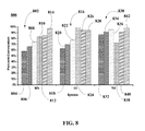
- FIG. 8 is a graphical representation illustrating a catalytic conversion efficiency comparison of NO X , CO, and THC conversions of an SPGM system resulting from isothermal oscillating testing of a third PGM loading of the standard PGM CCC as part of a plurality of SPGM catalyst configurations, according to an embodiment.
- FIG. 9 is a graphical representation illustrating lambda oscillation zones which characterize the catalytic conversion from conventional TWC systems and the disclosed SPGM TWC systems, according to an embodiment.
- Catalyst refers to one or more materials that may be of use in the conversion of one or more other materials.
- Platinum group metals refers to platinum, palladium, ruthenium, iridium, osmium, and rhodium.
- Zero PGM (ZPGM) catalyst refers to a catalyst completely or substantially free of platinum group metals.
- Synergized PGM (SPGM) catalyst refers to a PGM catalyst system which is synergized by a ZPGM compound under different configuration.
- Catalyst system refers to any system including a catalyst, such as, a PGM catalyst or a ZPGM catalyst of at least two layers comprising a substrate, a washcoat and/or an overcoat.
- Oxygen storage material refers to a material that absorbs oxygen from oxygen rich gas flows and further able to release oxygen into oxygen deficient gas flows.
- Synthesis method refers to a process by which chemical reactions occur to form a catalyst from different precursor materials.
- Three-Way Catalyst refers to a catalyst able to perform the three simultaneous tasks of reduction of nitrogen oxides to nitrogen and oxygen, oxidation of carbon monoxide to carbon dioxide, and oxidation of unburnt hydrocarbons to carbon dioxide and water.
- Spinel refers to any minerals of the general formulation AB 2 O 4 where the A ion and B ion are each selected from mineral oxides, such as, magnesium, iron, zinc, manganese, aluminum, chromium, or copper, amongst others.
- Close-coupled catalyst, or close-coupled catalytic converter, or pre-cat refers to a catalyst located in close proximity to the exhaust manifold of the engine and reduces cold-engine emissions by burning off hydrocarbons from the extra-rich mixture used to start a cold engine.
- Air/Fuel ratio or A/F ratio refers to the mass ratio of air to fuel present in a combustion process.
- R value refers to the value obtained by dividing the reducing potential of the catalyst by the oxidizing potential of the catalyst.
- Row condition refers to exhaust gas condition with an R value greater than 1.
- Lean condition refers to exhaust gas condition with an R value less than 1.
- “Lambda” refers to the ratio of (A) the ratio of the amount by weight of air divided by the amount by weight of fuel actually being fed to the engine at a point in time, to (B) the air/fuel stoichiometric ratio.
- Conversion refers to the chemical alteration of at least one material into one or more other materials.
- Catalytic Conversion efficiency refers to the ratio of the rate of mass removal within the catalytic converter of the particular constituent of interest to the mass flow rate of that constituent into the catalytic converter.
- the present disclosure describes the components of a catalytic converter system for treating the exhaust gas of an engine.
- the catalytic converter system components include a synergized platinum group metals catalyst (SPGM) system configuration that optionally includes a PGM underfloor catalyst.
- SPGM synergized platinum group metals catalyst
- the SPGM system configuration further includes a front spinel zone and a standard PGM close-coupled catalyst (CCC).
- FIG. 2 is a block diagram illustrating a synergized platinum group metals catalyst (SPGM) Three Way Catalyst (TWC) system portion of an engine system that includes a front spinel zone and a standard PGM CCC having PGM and Ce-based oxygen storage and further including a PGM underfloor catalyst, according to an embodiment.
- engine system 200 includes engine 104 and SPGM TWC system 210 .
- SPGM TWC system 210 further includes SPGM system 220 and PGM underfloor catalyst 106 .
- SPGM system 220 includes standard PGM CCC 102 and front spinel zone 202 .
- engine system 200 can include more components, less components, or different components depending on desired goals.
- elements having identical element numbers from previous figures perform in a substantially similar manner.
- engine 104 is mechanically coupled to and in fluidic communication with SPGM TWC system 210 .
- SPGM system 220 is mechanically coupled to and in fluidic communication with PGM underfloor catalyst 106 .
- SPGM TWC system 210 is configured to receive exhaust gases from engine 104 , process the received gases into underfloor treated exhaust gases, and expel the underfloor treated exhaust gases into the atmosphere.
- SPGM system 220 within SPGM TWC system 210 is configured to receive exhaust gases from engine 104 , process the received gases into SPGM treated gases, and expel the SPGM treated gases into PGM underfloor catalyst 106 for additional processing.
- front spinel zone 202 configured to receive exhaust gases from engine 104 , process the received gases into spinel treated gases, and expel the spinel treated gases into standard PGM CCC 102 for further processing.
- front spinel zone 202 within SPGM system 220 comprises a mixture of metal oxides and functions as both an oxygen storage material as well as a standard pre-catalyst for standard PGM CCC 102 .
- front spinel zone 202 is manufactured using any conventional synthesis method.
- the front spinel zone can be formed comprising a plurality of binary spinel compositions. Examples of suitable materials that these spinel structures can contain are aluminum, magnesium, manganese, gallium, nickel, copper, silver, cobalt, iron, chromium, titanium, tin, or mixtures thereof.
- front spinel zone 202 comprises Cu—Mn spinel structures.
- front spinel zone 202 is formed using Cu and Mn of suitable loadings for a Cu—Mn spinel coating of about one or two inches.
- a standard PGM close-coupled catalyst such as, for example standard PGM CCC 102 .
- front spinel zone 202 attenuates the air to fuel (A/F) ratio oscillations within the exhaust gases received from engine 104 into low amplitude oscillations prior to reaching standard PGM CCC 102 .
- the attenuation of the A/F ratio oscillations has a synergistic effect upon standard PGM CCCC 102 because the catalytic conversion efficiency is significantly enhanced even for a standard PGM CCC containing low PGM loading.
- FIG. 3 is a block diagram illustrating a TWC system portion of an engine system that includes a front spinel zone and a standard PGM CCC having PGM and Ce-based oxygen storage, according to an embodiment.
- engine system 300 includes engine 104 and SPGM system 220 .
- SPGM system 220 includes standard PGM CCC 102 and front spinel zone 202 .
- engine system 300 can include more components, less components, or different components depending on desired goals.
- elements having identical element numbers from previous figures perform in a substantially similar manner.
- engine 104 is mechanically coupled to and in fluidic communication with SPGM system 220 .
- SPGM system 220 is configured to receive exhaust gases from engine 104 , process the received gases into SPGM treated gases, and expel the SPGM treated gases into the atmosphere.
- front spinel zone 202 within SPGM system 220 is configured to receive exhaust gases from engine 104 , process the received gases into spinel treated gases, and expel the spinel treated gases into standard PGM CCC 102 for further processing.
- front spinel zone 202 within SPGM system 220 functions as a pre-catalyst.
- front spinel zone 202 when implemented using a mass ratio of spinel within spinel zone 202 to PGM within standard PGM CCC 102 and a particular loading of PGM material within standard PGM CCC 102 , enhanced catalytic conversion efficiency is achieved which obviates the need for an underfloor catalyst as part of the TWC system.
- front spinel zone 202 attenuates the A/F ratio oscillations within the exhaust gases received from engine 104 into low amplitude oscillations prior to reaching standard PGM CCC 102 .
- FIGS. 4, 5A, and 5B The attenuation benefits of the A/F ratio oscillations within the exhaust gases received from engine are described further in FIGS. 4, 5A, and 5B , below.
- the mass ratio of spinel within spinel zone 202 to PGM within standard PGM CCC 102 in conjunction with particular loadings of PGM material within standard PGM CCC 102 are described in FIGS. 6-8 , below.
- FIG. 4 is a block diagram illustrating analysis points in a SPGM TWC system including a front spinel zone and a standard PGM CCC having PGM and Ce-based oxygen storage, according to an embodiment.
- engine system 400 includes engine 104 , SPGM system 220 , and analysis point Q 402 .
- SPGM system 220 includes standard PGM CCC 102 , front spinel zone 202 , and analysis point R 404 .
- engine system 400 can include more components, less components, or different components depending on desired goals.
- elements having identical element numbers from previous figures perform in a substantially similar manner.
- analysis point Q 402 is located at the inlet port of front spinel zone 202 and analysis point R 404 is located the junction of the spinel material layer of front spinel zone 202 and the PGM layer of standard PGM CCC 102 .
- A/F perturbations are generated when the initial lean interval of an A/F ratio is greater than the stoichiometric value.
- This initial lean interval is followed by a series of rich intervals of A/F ratio that are lower than the stoichiometric value.
- the series of rich intervals of A/F ratios alternate with lean intervals of A/F ratios because the engine control system is reacting to exhaust gas sensors (not shown) located prior to SPGM system 220 .
- an efficiency value for the catalytic conversion capability of SPGM system 220 can be determined on the basis of the number of the A/F perturbations following the initial lean interval.
- the A/F perturbations possess high amplitudes at low frequencies.
- the amplitude of the A/F perturbations are reduced due to the synergistic effects generated by front spinel zone 202 .
- the A/F perturbations are reduced because the metal oxides of front spinel zone 202 act as a highly effective pre-oxygen storage material. Therefore, the amplitude of A/F ratio lambda is reduced to a significantly lower value.
- FIGS. 5A and 5B illustrate lambda oscillation waveforms of the A/F perturbations of a SPGM TWC system at specific points prior to the exhaust gas emissions entering a front spinel zone and then after the exhaust gas emissions leave the front spinel zone before reaching the standard PGM CCC, according to an embodiment.
- FIGS. 5A and 5B illustrate the lambda oscillation waveforms 500 and 550 of the A/F perturbations at specific points prior to the exhaust gas emissions entering ( FIG. 5A ) a front spinel zone and then after the exhaust gas emissions leave the front spinel zone ( FIG. 5B ) before reaching the standard PGM CCC, according to an embodiment.
- FIG. 5A is a graphical representation illustrating lambda oscillation waveforms 502 of the A/F perturbations at point Q 402 of the exemplary SPGM TWC system of FIG. 4 prior to the exhaust gas emissions from engine 104 entering front spinel zone 202 , according to an embodiment.
- the y-axis represents the amplitude value of the lambda oscillation ( ⁇ Q ) normalized to a value of 1 at the origin and the x-axis represents the frequency of the lambda oscillation.
- FIG. 5B is a graphical representation illustrating lambda oscillation waveforms 504 of the A/F perturbations at point R 404 of the exemplary SPGM TWC system of FIG. 4 prior to the exhaust gas emissions from engine 104 entering front spinel zone 202 , according to an embodiment.
- the y-axis represents the amplitude value of the lambda oscillation ( ⁇ R ) normalized to a value of 1 at the origin and the x-axis represents the frequency of the lambda oscillation.
- ⁇ R is much lower than ⁇ Q , the catalytic conversion efficiency of the disclosed TWC system is enhanced when the A/F ratio oscillations caused by the perturbations are maintained at very low amplitude near the stoichiometric point during operation under lean and rich conditions.
- TWC systems such as, for example the TWC systems as described in FIGS. 2 and 3 vary based on the combination of the PGM loadings of the standard PGM CCC and the particular SPGM catalyst configuration.
- conventional chemical techniques, deposition methods, and treatment systems can be employed in order to form the disclosed TWC system samples.
- TWC system samples are produced using variations of PGM loadings for the standard PGM CCC as well as various SPGM catalyst configurations.
- the TWC system samples include combinations of PGM material compositions of palladium (Pd) and rhodium (Rh).
- the TWC system samples include combinations of PGM material compositions of Pd.
- the standard PGM CCC within the disclosed TWC systems can be configured to include at least a layer of PGM catalyst material overlying a Ce-based oxygen storage material substrate.
- the plurality of catalyst samples produced includes standard PGM CCC samples including loadings of about 6 g/ft 3 of Pd and of about 6 g/ft 3 of Rh; standard PGM CCC samples including loadings of about 12 g/ft 3 of Pd and of about 6 g/ft 3 of Rh; and standard PGM CCC samples including loading of about 20 g/ft 3 of Pd.
- the Cu—Mn spinel is coated on standard PGM CCC.
- TWC system samples are produced to include for each of the PGM loadings described above and used for the standard PGM CCC samples.
- weight ratios of 60% Cu—Mn spinel with 40% PGM CCC are used, herein referred to as SPGM systems Type 1A, Type 2A, and Type 3A, respectively.
- TWC system samples are produced to include for each of the PGM loadings described above and used for the standard PGM CCC samples. Further to these exemplary embodiments, weight ratios of 40% Cu—Mn spinel with 60% PGM CCC are used, herein referred to as SPGM systems Type 1B, Type 2B, and Type 3B, respectively.
- reference samples are produced for catalytic conversion comparisons and to ascertain the significant catalytic conversion efficiency of disclosed TWC system configurations.
- the reference samples produced include sample configurations of 60% by weight of a front zone having no spinel material (blank front zone) and 40% by weight of standard PGM CCC sample comprising the plurality of PGM loadings previously described. These samples are herein referred to as standard PGM CCC reference samples Type 1C, Type 2C, and Type 3C, respectively.
- the reference samples produced include sample configurations of 40% by weight of a blank front zone and 60% by weight of standard PGM CCC sample comprising the plurality of PGM loadings previously described. These samples are herein referred to as standard PGM CCC reference samples Type 1D, Type 2D, and Type 3D, respectively.
- the reference samples prepared include samples including 100% by weight of standard PGM CCC sample, comprising the plurality of PGM loadings previously described. These samples are herein referred to as standard PGM CCC reference samples Type 1E, Type 2E, and Type 3E, respectively.
- reference samples are produced to include a 100% Cu—Mn spinel, herein referred to as ZPGM reference samples.
- the synergistic effect of the front spinel zone and the catalytic performance of the disclosed catalyst systems can be tested and compared for all variations of the prepared samples.
- testing is conducted by performing a series of isothermal oscillating tests by employing a simulated TWC exhaust gas composition fed into a flow reactor at a selected isothermal temperature and frequency, using a suitable A/F ratio span and space velocity.
- the TWC isothermal oscillating testing is conducted employing a flow reactor.
- the temperature is increase from about 100° C. to about 500° C. at a rate of about 40° C./min.
- a gas composition of 8,000 ppm of CO, 400 ppm of C 3 H 6 , 100 ppm of C 3 H 8 , 1,000 ppm of NO R , 2,000 ppm of H 2 , 10% of CO 2 , 10% of H 2 O, and O 2 oscillating between about 0.3% to about 0.45% by volume is fed into the flow reactor.
- temperature within the flow reactor and the gas composition represent the three-way condition of the control loop in an exhaust system, where the air-fuel ratio (A/F) oscillates between rich and lean conditions of about four seconds each, respectively.
- the average R-value is about 1.05, at space velocity of about 40,000 h ⁇ 1 .
- the TWC isothermal oscillating test is conducted, under a frequency of about 0.125 Hz, with ⁇ 0.8 A/F ratio span, and at an inlet temperature of about 550° C.
- FIG. 6 is a graphical representation illustrating a catalytic conversion efficiency comparison of NO X , CO, and THC conversions of an SPGM system resulting from isothermal oscillating testing of a first PGM loading of the standard PGM CCC as part of a plurality of SPGM catalyst configurations, according to an embodiment.
- the plurality of system samples include SPGM system samples Type 1A and Type 1B, standard PGM CCC reference samples Type 1C, 1D, and 1E, and ZPGM reference samples, as detailed in Table 1 below.
- conversion comparison bar 602 illustrates NO X , CO, and THC conversions respectively, for the catalyst samples detailed in Table 1.
- the SPGM systems Type 1A and SPGM systems Type 1B exhibit significant levels of catalytic conversion efficiency.
- SPGM system Type 1A exhibits 99% NO X conversion (bar 612 ), 97% CO conversion (bar 626 ), and 92% THC conversion (bar 640 ).
- SPGM system Type 1B exhibits 98% NO X conversion (bar 614 ), 96% CO conversion (bar 628 ), and 97% THC conversion (bar 642 ).
- the standard PGM CCC reference samples Type 1E exhibit NO X conversion of 76%, CO conversion of 89%, and THC conversion of 94%, respectively, as illustrated in bar 608 , bar 622 , and bar 636 of FIG. 6 .
- FIG. 7 is a graphical representation illustrating a catalytic conversion efficiency comparison of NO X , CO, and THC conversions of an SPGM system resulting from isothermal oscillating testing of a second PGM loading of the standard PGM CCC as part of a plurality of SPGM catalyst configurations, according to an embodiment.
- the plurality of system samples includes SPGM system samples Type 2A and Type 2B, standard PGM CCC reference samples Type 2C, 2D, and 2E, and ZPGM reference samples, as detailed in Table 2 below.
- conversion comparison bar 702 illustrates NO X , CO, and THC conversions respectively, for the catalyst samples detailed in Table 2.
- the SPGM systems Type 2A and SPGM systems Type 2B exhibit significant levels of catalytic conversion efficiency.
- SPGM system Type 2A exhibits 99% NO X conversion (bar 712 ), 97% CO conversion (bar 726 ), and 93% THC conversion (bar 740 ).
- SPGM system Type 2B exhibits 98% NO X conversion (bar 714 ), 97% CO conversion (bar 728 ), and 98% THC conversion (bar 742 ).
- the standard PGM CCC reference samples Type 2E exhibit NO X conversion of 77%, CO conversion of 89%, and THC conversion of 95%, respectively, as illustrated in bar 708 , bar 722 , and bar 736 of FIG. 7 .
- FIG. 8 is a graphical representation illustrating a catalytic conversion efficiency comparison of NO X , CO, and THC conversions of an SPGM system resulting from isothermal oscillating testing of a third PGM loading of the standard PGM CCC as part of a plurality of SPGM catalyst configurations, according to an embodiment.
- the plurality of system samples includes SPGM system samples Type 3A and Type 3B, CCC reference samples Type 3C, 3D, and 3E, and ZPGM reference samples, as detailed in Table 3 below.
- conversion comparison bar 802 illustrates NO X , CO, and THC conversions respectively, for the catalyst samples detailed in Table 3.
- the SPGM systems Type 3A and SPGM systems Type 3B exhibit significant levels of catalytic conversion efficiency.
- SPGM system Type 3A exhibits 85% NO X conversion (bar 812 ), 94% CO conversion (bar 826 ), and 91% THC conversion (bar 840 ).
- SPGM system Type 3B exhibits 97% NO X conversion (bar 814 ), 94% CO conversion (bar 828 ), and 98% THC conversion (bar 842 ).
- the standard PGM CCC reference samples Type 3E exhibit NO X conversion of 74%, CO conversion of 77%, and THC conversion of 95%, respectively, as illustrated in bar 808 , bar 822 , and bar 836 of FIG. 8 .
- FIGS. 6-8 When all types of SPGM system samples are compared for catalytic conversion efficiency, in FIGS. 6-8 can be observed that the most significant system performance is provided by the SPGM systems Type 2A and Type 2B, followed by the SPGM systems Type 1A and Type 1B, and subsequently, the SPGM systems Type 3A and Type 3B.
- all the disclosed SPGM systems can be utilized for different TWC applications because of the significant conversion efficiencies that resulted from the TWC isothermal oscillating tests performed on the plurality of SPGM system samples.
- the underfloor or clean-up PGM-based catalyst can be included as a component of the intended exhaust system.
- the enhanced and significant catalytic conversion efficiency of the disclosed SPGM system configurations and the provided attenuation of the A/F perturbations enable the removal of the conventional underfloor or clean-up PGM-based catalyst used in current TWC systems.
- FIG. 9 is a graphical representation illustrating lambda oscillation zones which characterize the catalytic conversion from conventional TWC systems and disclosed SPGM TWC systems, according to an embodiment.
- conversion curve 902 represents NO X conversion
- conversion curve 904 represents for HC conversion
- conversion curve 906 represents CO conversion for a TWC system configuration, such as, for example the configuration of TWC system 100 , as described in FIG. 1 .
- the system operates within A/F ratio lambda zone 910 , where A/F perturbations are high as a result of the wide range of A/F ratio around the stoichiometric point marked by line 908 .
- A/F perturbations are high as a result of the wide range of A/F ratio around the stoichiometric point marked by line 908 .
- the catalytic performance in NO X conversion remains at about 100% conversion for lean conditions, at the R value range between about 0.96 and less than about 0.99.
- the NO X conversion declines to about 40% or less for rich conditions at R values greater than about 1.005 close to stoichiometric to R values less than about 1.03.
- A/F ratio lambda zone 920 indicates the operation of disclosed SPGM TWC system configurations, as described in FIGS. 2 and 3 .
- catalytic performance in NO X conversion, HC conversion, and CO conversion is significantly high and stable, at R values very close to the stoichiometric point for both lean and rich conditions.
- the range of R values for operation within this zone is greater than about 0.99 and less than about 1.005.
- the present disclosure confirms that PGM catalysts alone and ZPGM catalysts of binary spinel alone may not provide significantly high catalytic conversion efficiency as can be provided by the disclosed SPGM systems, which include a synergized standard PGM CCC with a front spinel zone.
- the disclosed SPGM systems for TWC applications are catalyst systems of significantly high catalytic conversion efficiency and attenuated A/F perturbations.
Abstract
Description
| TABLE 1 |
| % NOX, CO, and THC conversions for each of the samples tested |
| including PGM loadings of 6 g/ft3 Pd and 6 g/ft3 Rh. |
| % | Associated | ||
| Type of Sample | Pollutant | Conversion | Element |
| CCC reference sample Type 1C | NOX | 64 | 604 | |
| CCC reference sample | NO | X | 70 | 606 |
| CCC reference sample Type 1E | NOX | 76 | 608 | |
| ZPGM reference sample | NOX | 83 | 610 | |
| SPGM system Type 1A | NOX | 99 | 612 | |
| SPGM system Type 1B | NOX | 98 | 614 | |
| CCC reference sample Type 1C | CO | 81 | 618 | |
| CCC reference sample Type 1D | CO | 86 | 620 | |
| CCC reference sample Type 1E | CO | 89 | 622 | |
| ZPGM reference sample | CO | 98 | 624 | |
| SPGM system Type 1A | CO | 97 | 626 | |
| SPGM system Type 1B | CO | 96 | 628 | |
| CCC reference sample Type 1C | THC | 82 | 632 | |
| CCC reference sample Type 1D | THC | 89 | 634 | |
| CCC reference sample Type 1E | THC | 94 | 636 | |
| ZPGM reference sample | THC | 72 | 638 | |
| SPGM system Type 1A | THC | 92 | 640 | |
| SPGM system Type 1B | THC | 97 | 642 | |
| TABLE 2 |
| % NOX, CO, and THC conversions for each of the samples tested |
| including PGM loadings of 12 g/ft3 Pd and 6 g/ft3 Rh. |
| % | Associated | ||
| Type of Sample | Pollutant | Conversion | Element |
| CCC reference sample Type, 2C | NOX | 64 | 704 |
| CCC reference sample Type 2D | NOX | 69 | 706 |
| CCC reference sample Type 2E | NOX | 77 | 708 |
| ZPGM reference sample | NOX | 83 | 710 |
| SPGM system Type 2A | NOX | 99 | 712 |
| SPGM system Type 2B | NOX | 98 | 714 |
| CCC reference sample Type 2C | CO | 79 | 718 |
| CCC reference sample Type 2D | CO | 85 | 720 |
| CCC reference sample Type 2E | CO | 89 | 722 |
| ZPGM reference sample | CO | 98 | 724 |
| SPGM system Type 2A | CO | 97 | 726 |
| SPGM system Type 2B | CO | 97 | 728 |
| CCC reference sample Type 2C | THC | 85 | 732 |
| CCC reference sample Type 2D | THC | 91 | 734 |
| CCC reference sample Type 2E | THC | 95 | 736 |
| ZPGM reference sample | THC | 72 | 738 |
| SPGM system Type 2A | THC | 93 | 740 |
| SPGM system Type 2B | THC | 98 | 742 |
| TABLE 3 |
| % NOX, CO, and THC conversions for each of the samples tested |
| including PGM loadings of 20 g/ft3 Pd. |
| % | Associated | ||
| Type of Sample | Pollutant | Conversion | Element |
| CCC reference sample Type 3C | NOX | 58 | 804 | |
| CCC reference sample Type 3D | NOX | 66 | 806 | |
| CCC reference sample Type 3E | NOX | 74 | 808 | |
| ZPGM reference sample | NOX | 83 | 810 | |
| SPGM system Type 3A | NOX | 85 | 812 | |
| SPGM system Type 3B | NOX | 97 | 814 | |
| CCC reference sample Type 3C | CO | 62 | 818 | |
| CCC reference sample | CO | 70 | 820 | |
| CCC reference sample Type 3E | CO | 77 | 822 | |
| ZPGM reference sample | CO | 98 | 824 | |
| SPGM system Type 3A | CO | 94 | 826 | |
| SPGM system Type 3B | CO | 94 | 828 | |
| CCC reference sample Type 3C | THC | 87 | 832 | |
| CCC reference sample Type 3D | THC | 91 | 834 | |
| CCC reference sample Type 3E | THC | 95 | 836 | |
| ZPGM reference sample | THC | 72 | 838 | |
| SPGM system Type 3A | THC | 91 | 840 | |
| SPGM system Type 3B | THC | 98 | 842 | |
Claims (13)
Priority Applications (3)
| Application Number | Priority Date | Filing Date | Title |
|---|---|---|---|
| US14/657,842 US9700841B2 (en) | 2015-03-13 | 2015-03-13 | Synergized PGM close-coupled catalysts for TWC applications |
| PCT/IB2016/051416 WO2016147094A1 (en) | 2015-03-13 | 2016-03-11 | Synergized pgm close-coupled catalysts for twc applications |
| CN201680027248.4A CN107580651A (en) | 2015-03-13 | 2016-03-11 | PGM Close-coupled catalysts for the collaboration of TWC applications |
Applications Claiming Priority (1)
| Application Number | Priority Date | Filing Date | Title |
|---|---|---|---|
| US14/657,842 US9700841B2 (en) | 2015-03-13 | 2015-03-13 | Synergized PGM close-coupled catalysts for TWC applications |
Publications (2)
| Publication Number | Publication Date |
|---|---|
| US20160263526A1 US20160263526A1 (en) | 2016-09-15 |
| US9700841B2 true US9700841B2 (en) | 2017-07-11 |
Family
ID=55650610
Family Applications (1)
| Application Number | Title | Priority Date | Filing Date |
|---|---|---|---|
| US14/657,842 Expired - Fee Related US9700841B2 (en) | 2015-03-13 | 2015-03-13 | Synergized PGM close-coupled catalysts for TWC applications |
Country Status (3)
| Country | Link |
|---|---|
| US (1) | US9700841B2 (en) |
| CN (1) | CN107580651A (en) |
| WO (1) | WO2016147094A1 (en) |
Cited By (1)
| Publication number | Priority date | Publication date | Assignee | Title |
|---|---|---|---|---|
| US10738256B1 (en) | 2017-12-22 | 2020-08-11 | TerSol, LLC | Fuel additive systems, compositions, and methods |
Families Citing this family (8)
| Publication number | Priority date | Publication date | Assignee | Title |
|---|---|---|---|---|
| US9731279B2 (en) | 2014-10-30 | 2017-08-15 | Clean Diesel Technologies, Inc. | Thermal stability of copper-manganese spinel as Zero PGM catalyst for TWC application |
| US9700841B2 (en) | 2015-03-13 | 2017-07-11 | Byd Company Limited | Synergized PGM close-coupled catalysts for TWC applications |
| US9951706B2 (en) | 2015-04-21 | 2018-04-24 | Clean Diesel Technologies, Inc. | Calibration strategies to improve spinel mixed metal oxides catalytic converters |
| US10533472B2 (en) | 2016-05-12 | 2020-01-14 | Cdti Advanced Materials, Inc. | Application of synergized-PGM with ultra-low PGM loadings as close-coupled three-way catalysts for internal combustion engines |
| US9861964B1 (en) | 2016-12-13 | 2018-01-09 | Clean Diesel Technologies, Inc. | Enhanced catalytic activity at the stoichiometric condition of zero-PGM catalysts for TWC applications |
| US10265684B2 (en) | 2017-05-04 | 2019-04-23 | Cdti Advanced Materials, Inc. | Highly active and thermally stable coated gasoline particulate filters |
| GB2582614A (en) | 2019-03-28 | 2020-09-30 | Johnson Matthey Plc | An exhaust gas treatment system and the use thereof for the treatment of an exhaust gas |
| JP7136070B2 (en) * | 2019-11-29 | 2022-09-13 | トヨタ自動車株式会社 | Exhaust gas purification system |
Citations (166)
| Publication number | Priority date | Publication date | Assignee | Title |
|---|---|---|---|---|
| US4629472A (en) | 1985-06-19 | 1986-12-16 | Fuel Tech, Inc. | Method and apparatus for improving combustion, thermal efficiency and reducing emissions by treating fuel |
| US4891050A (en) | 1985-11-08 | 1990-01-02 | Fuel Tech, Inc. | Gasoline additives and gasoline containing soluble platinum group metal compounds and use in internal combustion engines |
| US4892562A (en) | 1984-12-04 | 1990-01-09 | Fuel Tech, Inc. | Diesel fuel additives and diesel fuels containing soluble platinum group metal compounds and use in diesel engines |
| WO1990007561A1 (en) | 1988-12-28 | 1990-07-12 | Fuel Tech, Inc. | Method for reducing emissions from or increasing the utilizable energy of fuel for powering internal combustion engines |
| US5034020A (en) | 1988-12-28 | 1991-07-23 | Platinum Plus, Inc. | Method for catalyzing fuel for powering internal combustion engines |
| US5168836A (en) | 1990-08-08 | 1992-12-08 | Catalytic Solutions, Inc. | Emission control system |
| US5203166A (en) | 1991-02-22 | 1993-04-20 | Miller John W | Method and apparatus for treating diesel exhaust gas to remove fine particulate matter |
| US5266083A (en) | 1988-12-28 | 1993-11-30 | Platinum Plus, Inc. | Method for reducing pollution emissions from a diesel engine |
| WO1994011467A1 (en) | 1992-11-10 | 1994-05-26 | Platinum Plus, Inc. | Method for reducing harmful emissions from a diesel engine equipped with a particulate trap |
| WO1995002655A1 (en) | 1993-07-12 | 1995-01-26 | Platinum Plus, Inc. | METHOD FOR REDUCING EMISSIONS OF NOx AND PARTICULATES FROM A DIESEL ENGINE |
| US5404841A (en) | 1993-08-30 | 1995-04-11 | Valentine; James M. | Reduction of nitrogen oxides emissions from diesel engines |
| US5501714A (en) | 1988-12-28 | 1996-03-26 | Platinum Plus, Inc. | Operation of diesel engines with reduced particulate emission by utilization of platinum group metal fuel additive and pass-through catalytic oxidizer |
| US5584894A (en) | 1992-07-22 | 1996-12-17 | Platinum Plus, Inc. | Reduction of nitrogen oxides emissions from vehicular diesel engines |
| WO1997004045A1 (en) | 1995-07-18 | 1997-02-06 | Clean Diesel Technologies, Inc. | Methods for reducing harmful emissions from a diesel engine |
| WO1997009523A1 (en) | 1995-09-01 | 1997-03-13 | Clean Diesel Technologies, Inc. | Methods for improving the operation of a catalyzed engine |
| EP0779095A1 (en) | 1995-12-13 | 1997-06-18 | Daimler-Benz Aktiengesellschaft | Process and device for catalytic gas purification |
| WO1997028358A1 (en) | 1996-01-31 | 1997-08-07 | Clean Diesel Technologies, Inc. | Method and apparatus for reducing harmful emissions from a diesel engine by post combustion catalyst injection |
| WO1997036676A1 (en) | 1996-04-02 | 1997-10-09 | Clean Diesel Technologies, Inc. | Method and apparatus for reducing harmful emissions from a diesel engine by urea injection scr |
| US5693106A (en) | 1992-07-22 | 1997-12-02 | Platinum Plus, Inc. | Platinum metal fuel additive for water-containing fuels |
| US5732548A (en) | 1994-10-07 | 1998-03-31 | Platinum Plus, Inc. | Method for reducing harmful emissions from two-stroke engines |
| US5743922A (en) | 1992-07-22 | 1998-04-28 | Nalco Fuel Tech | Enhanced lubricity diesel fuel emulsions for reduction of nitrogen oxides |
| US5749928A (en) | 1984-12-04 | 1998-05-12 | Platinum Plus, Inc. | Method for reducing emissions from or increasing the utilizable energy of fuel for powering internal combustion engines |
| WO1998022209A1 (en) | 1996-11-20 | 1998-05-28 | Clean Diesel Technologies, Inc. | SELECTIVE CATALYTIC NOx REDUCTION UTILIZING UREA WITHOUT CATALYST FOULING |
| WO1998028070A1 (en) | 1996-12-20 | 1998-07-02 | Clean Diesel Technologies, Inc. | Method and apparatus for reducing harmful emissions from a lean-burn engine by urea injection scr |
| US5809774A (en) | 1996-11-19 | 1998-09-22 | Clean Diesel Technologies, Inc. | System for fueling and feeding chemicals to internal combustion engines for NOx reduction |
| US5809775A (en) | 1997-04-02 | 1998-09-22 | Clean Diesel Technologies, Inc. | Reducing NOx emissions from an engine by selective catalytic reduction utilizing solid reagents |
| US5868421A (en) | 1995-11-02 | 1999-02-09 | Trw Occupant Restraint Systems Gmbh | Gas bag lateral impact protective device |
| US5921080A (en) | 1997-03-07 | 1999-07-13 | The Lubrizol Corporation | Oxidation catalytic converter system for small spark ignited engines |
| US5924280A (en) | 1997-04-04 | 1999-07-20 | Clean Diesel Technologies, Inc. | Reducing NOx emissions from an engine while maximizing fuel economy |
| US5939354A (en) | 1996-04-10 | 1999-08-17 | Catalytic Solutions, Inc. | Perovskite-type metal oxide compounds and method for preparing the compounds |
| EP0945177A2 (en) | 1998-03-25 | 1999-09-29 | Basf Aktiengesellschaft | Method for producing spinel extrudates |
| US5968464A (en) | 1997-05-12 | 1999-10-19 | Clean Diesel Technologies, Inc. | Urea pyrolysis chamber and process for reducing lean-burn engine NOx emissions by selective catalytic reduction |
| US5976475A (en) | 1997-04-02 | 1999-11-02 | Clean Diesel Technologies, Inc. | Reducing NOx emissions from an engine by temperature-controlled urea injection for selective catalytic reduction |
| US5977017A (en) | 1996-04-10 | 1999-11-02 | Catalytic Solutions, Inc. | Perovskite-type metal oxide compounds |
| US6003303A (en) | 1993-01-11 | 1999-12-21 | Clean Diesel Technologies, Inc. | Methods for reducing harmful emissions from a diesel engine |
| US6023928A (en) | 1997-04-17 | 2000-02-15 | Clean Diesel Technologies, Inc. | Method for reducing emissions from a diesel engine |
| US6051040A (en) | 1988-12-28 | 2000-04-18 | Clean Diesel Technologies, Inc. | Method for reducing emissions of NOx and particulates from a diesel engine |
| US6063350A (en) | 1997-04-02 | 2000-05-16 | Clean Diesel Technologies, Inc. | Reducing nox emissions from an engine by temperature-controlled urea injection for selective catalytic reduction |
| WO2000030739A1 (en) | 1998-11-24 | 2000-06-02 | Clean Diesel Technologies, Inc. | Catalyzed particulate oxidizer for reducing particulate emissions from a diesel engine and method |
| US6124130A (en) | 1998-08-10 | 2000-09-26 | Clean Diesel Technologies, Inc. | Microbial catalyst for desulfurization of fossil fuels |
| WO2000075643A1 (en) | 1999-06-09 | 2000-12-14 | Clean Diesel Technologies, Inc. | METHODS AND COMPOSITIONS FOR ASSURING REDUCTION OF NOx EMISSIONS FROM AN ENGINE BY SELECTIVE CATALYTIC REDUCTION |
| WO2001008587A1 (en) | 1999-07-28 | 2001-02-08 | 3M Innovative Properties Company | Orthodontic force module with fracture-resistant coupling |
| US20010001354A1 (en) | 1997-01-31 | 2001-05-24 | Peter-Hoblyn Jeremy D. | Method and composition for reducing emissions from a gasoline engine equipped with a three-way catalytic converter |
| US6279603B1 (en) | 1998-10-01 | 2001-08-28 | Ambac International | Fluid-cooled injector |
| US6361754B1 (en) | 1997-03-27 | 2002-03-26 | Clean Diesel Technologies, Inc. | Reducing no emissions from an engine by on-demand generation of ammonia for selective catalytic reduction |
| US20030109047A1 (en) | 2001-11-09 | 2003-06-12 | Valentine James M. | Continuously-variable control of pollution reducing chemicals for combustion sources |
| US20030126789A1 (en) | 2000-05-09 | 2003-07-10 | Valentine James M. | Low-emissions diesel fuel |
| US20030148235A1 (en) | 2002-02-04 | 2003-08-07 | Valentine James M. | Reduced-emissions combustion utilizing multiple-component metallic combustion catalyst |
| WO2003068363A1 (en) | 2002-02-12 | 2003-08-21 | Clean Diesel Technologies, Inc. | Multi-stage exhaust gas purifier |
| US20030185722A1 (en) | 2002-04-02 | 2003-10-02 | Tetsuro Toyoda | Carbon particle reducing apparatus |
| US20030198582A1 (en) | 1996-04-10 | 2003-10-23 | Catalytic Solutions, Inc. | Perovskite-type metal oxide compounds and methods of making and using thereof |
| US20040098905A1 (en) | 2000-09-28 | 2004-05-27 | Valentine James M. | Low-emissions diesel fuel emulsions |
| WO2004058641A1 (en) | 2002-12-17 | 2004-07-15 | Clean Diesel Technologies, Inc. | Nox control for ic engines |
| US20040172876A1 (en) | 2002-03-22 | 2004-09-09 | Sprague Barry N. | Catalytic metal additive concentrate and method of making and using |
| US20050132674A1 (en) | 2003-12-18 | 2005-06-23 | Tetsuro Toyoda | Particulate matter reducing apparatus |
| US20050160663A1 (en) | 2000-08-01 | 2005-07-28 | Valentine James M. | Cleaner burning diesel fuel |
| US20050164139A1 (en) | 2002-02-04 | 2005-07-28 | Valentine James M. | Reduced-emissions combustion utilizing multiple-component metallic combustion catalyst and lightly catalyzed diesel particulate filter |
| US20050160724A1 (en) | 2002-02-04 | 2005-07-28 | Valentine James M. | Reduced-emissions combustion utilizing multiple-component metallic combustion catalyst and lightly catalyzed diesel oxidation catalyst |
| US20050188605A1 (en) | 2000-08-01 | 2005-09-01 | Valentine James M. | Reduced-emissions combustion utilizing multiple-component metallic combustion catalyst |
| US20050217751A1 (en) | 2004-03-05 | 2005-10-06 | Valentine James M | Gravity feed ball-in-seat valve with extension unit for dosing fuel additives |
| US20060120936A1 (en) | 2004-10-14 | 2006-06-08 | Catalytic Solutions, Inc. | Platinum group metal-free catalysts for reducing the ignition temperature of particulates on a diesel particulate filter |
| US20060166816A1 (en) | 2004-06-23 | 2006-07-27 | Catalytic Solutions, Inc. | Catalysts and processes for selective hydrogenation of acetylene and dienes in light olefin feedstreams |
| US20060228283A1 (en) | 2005-02-28 | 2006-10-12 | Catalytic Solutions, Inc. | Catalyst and method for reducing nitrogen oxides in exhaust streams with hydrocarbons or alcohols |
| US20060254535A1 (en) | 2004-12-23 | 2006-11-16 | Clean Diesel Technologies, Inc. | Engine on pulsed fuel additive concentrate dosing system and controller |
| US20060260185A1 (en) | 2005-04-28 | 2006-11-23 | Clean Diesel Technologies, Inc. | Fuel Additive and Catalyst Treatment Process |
| US20070015656A1 (en) | 2005-07-18 | 2007-01-18 | Valentine James M | Fuel Additive and Fuel Treatment Process |
| US20070209272A1 (en) | 2000-08-01 | 2007-09-13 | Valentine James M | Low-emissions diesel fuel blend |
| US20070283681A1 (en) | 2006-05-18 | 2007-12-13 | Clean Diesel Technologies, Inc. | Diesel particulate control |
| US20080210184A1 (en) | 2004-07-01 | 2008-09-04 | Clean Diesel Technologies, Inc. | Fuel Additive Concentrate Dosing System |
| US20090004083A1 (en) | 2003-12-17 | 2009-01-01 | Valentine James M | NOx control for IC engines |
| US7527776B2 (en) | 2007-01-09 | 2009-05-05 | Catalytic Solutions, Inc. | Ammonia SCR catalyst and method of using the catalyst |
| WO2009139860A1 (en) | 2008-05-15 | 2009-11-19 | Catalytic Solutions, Inc. | Emission reduction system for use with a heat recovery steam generation system |
| US20090304566A1 (en) | 2007-01-09 | 2009-12-10 | Golden Stephen J | Ammonia scr catalyst and method of using the catalyst |
| US20090324468A1 (en) | 2008-06-27 | 2009-12-31 | Golden Stephen J | Zero platinum group metal catalysts |
| US20090324469A1 (en) | 2008-06-27 | 2009-12-31 | Golden Stephen J | Zero platinum group metal catalysts |
| US7641875B1 (en) | 2000-11-15 | 2010-01-05 | Catalytic Solutions, Inc. | Mixed-phase ceramic oxide three-way catalyst formulations and methods for preparing the catalysts |
| US20100316547A1 (en) | 2009-05-20 | 2010-12-16 | Rachelle Justice | Catalysts for lean burn engines |
| WO2011068509A1 (en) | 2009-12-02 | 2011-06-09 | Catalytic Solutions, Inc. | Mixed-phase ceramic oxide three-way catalyst formulations and methods for preparing the catalysts |
| US20120183447A1 (en) | 2008-04-30 | 2012-07-19 | Yul Kwan | Method of reducing nitrogen oxides in a gas stream with vaporized ammonia |
| US20130115144A1 (en) | 2011-08-10 | 2013-05-09 | Clean Diesel Technologies, Inc. | Catalyst with Lanthanide-Doped Zirconia and Methods of Making |
| US20130236380A1 (en) | 2011-08-10 | 2013-09-12 | Clean Diesel Technologies, Inc. | Palladium solid solution catayst and methods of making |
| US8802582B2 (en) | 2007-01-09 | 2014-08-12 | Catalytic Solutions, Inc. | High temperature ammonia SCR catalyst and method of using the catalyst |
| US20140274663A1 (en) | 2013-03-15 | 2014-09-18 | Cdti | Firing (Calcination) Process and Method Related to Metallic Substrates Coated with ZPGM Catalyst |
| US20140274677A1 (en) | 2013-03-15 | 2014-09-18 | Cdti | System and Method for Optimized Oxygen Storage Capacity and Stability of OSM Without Rare Metals |
| US20140271391A1 (en) | 2013-03-15 | 2014-09-18 | Cdti | ZPGM TWC Systems Compositions and Methods Thereof |
| US20140274675A1 (en) | 2013-03-15 | 2014-09-18 | Cdti | Oxidation Catalyst Systems Compositions and Methods Thereof |
| US20140271388A1 (en) * | 2013-03-15 | 2014-09-18 | Cdti | Formation and Stability of Cu-Mn Spinel Phase for ZPGM Catalyst Systems |
| US20140271393A1 (en) | 2013-03-15 | 2014-09-18 | Cdti | Methods for Variation of Support Oxide Materials for ZPGM Oxidation Catalysts and Systems Using Same |
| US20140274678A1 (en) | 2013-03-15 | 2014-09-18 | Cdti | Coating Process of Zero-PGM Catalysts and Methods Thereof |
| US20140271425A1 (en) | 2013-03-15 | 2014-09-18 | Cdti | Methods for Oxidation and Two-way and Three-way ZPGM Catalyst Systems and Apparatus Comprising Same |
| US20140271387A1 (en) | 2013-03-15 | 2014-09-18 | Cdti | Optimal Composition of Copper-Manganese Spinel in ZPGM Catalyst for TWC Applications |
| US20140271390A1 (en) | 2013-03-15 | 2014-09-18 | Cdti | ZPGM Catalyst Systems and Methods of Making Same |
| US20140271392A1 (en) | 2013-03-15 | 2014-09-18 | Cdti | System and Method for Two and Three Way ZPGM Catalyst |
| US20140274674A1 (en) | 2013-03-15 | 2014-09-18 | Cdti | Influence of Support Oxide Materials on Coating Processes of ZPGM Catalyst Materials for TWC Applications |
| US20140271384A1 (en) | 2013-03-15 | 2014-09-18 | Cdti | System and Methods for using Copper- Manganese- Iron Spinel as Zero PGM Catalyst for TWC Applications |
| US8845987B1 (en) | 2013-11-26 | 2014-09-30 | Clean Diesel Technologies Inc. (CDTI) | Method for improving lean performance of PGM catalyst systems: synergized PGM |
| US8853121B1 (en) | 2013-10-16 | 2014-10-07 | Clean Diesel Technology Inc. | Thermally stable compositions of OSM free of rare earth metals |
| US20140301906A1 (en) | 2013-04-04 | 2014-10-09 | Cdti | Three Way Catalyst Double Impregnation Composition and Method Thereof |
| US20140298714A1 (en) | 2013-04-04 | 2014-10-09 | Cdti | Fuel Borne Catalysts for Sulfur Rich Fuels |
| US20140301909A1 (en) | 2013-04-04 | 2014-10-09 | Cdti | System and Method for ZPGM Catalytic Converters |
| US20140301931A1 (en) | 2013-04-04 | 2014-10-09 | Cdti | System and Method for Two and Three Way Mixed Metal Oxide ZPGM Catalyst |
| US20140301926A1 (en) | 2013-04-04 | 2014-10-09 | Cdti | Systems and Methods for Diesel Oxidation Catalyst with Decreased SO3 Emissions |
| US20140302983A1 (en) | 2013-04-04 | 2014-10-09 | Cdti | System and Method for Two and Three Way NB-ZR Catalyst |
| US20140336044A1 (en) | 2013-05-10 | 2014-11-13 | Cdti | Copper-Manganese Spinel Catalysts and Methods of Making Same |
| US20140335626A1 (en) | 2013-05-10 | 2014-11-13 | Cdti | Test Bench Gas Flow Control System and Method |
| US20140334989A1 (en) | 2013-05-10 | 2014-11-13 | Cdti | ZPGM Diesel Oxidation Catalysts and Methods of Making and Using Same |
| US20140335625A1 (en) | 2013-05-10 | 2014-11-13 | Cdti | Temperature Control Method in a Laboratory Scale Reactor |
| US20140334990A1 (en) | 2013-05-10 | 2014-11-13 | Cdti | ZPGM Diesel Oxidation Catalyst Systems and Methods Thereof |
| US20140336045A1 (en) | 2013-05-10 | 2014-11-13 | Cdti | Perovskite and Mullite-like Structure Catalysts for Diesel Oxidation and Method of Making Same |
| US20140334978A1 (en) | 2013-05-10 | 2014-11-13 | Cdti | System and Apparatus for a Laboratory Scale Reactor |
| US20140336038A1 (en) | 2013-05-10 | 2014-11-13 | Cdti | ZPGM Catalytic Converters (TWC application) |
| US20140356243A1 (en) | 2013-05-29 | 2014-12-04 | Cdti | Systems and Methods for Providing ZPGM Perovskite Catalyst for Diesel Oxidation Applications |
| US20140357475A1 (en) | 2013-05-29 | 2014-12-04 | Cdti | Systems and Methods Using Cu-Mn Spinel Catalyst on Varying Carrier Material Oxides for TWC Applications |
| US20140357479A1 (en) | 2013-05-29 | 2014-12-04 | Cdti | Variations for Synthesizing Zero Platinum Group Metal Catalyst Systems |
| WO2014194101A1 (en) | 2013-05-29 | 2014-12-04 | Clean Diesel Technologies, Inc. | Zpgm diesel oxidation catalyst systems |
| US20140364303A1 (en) | 2013-06-06 | 2014-12-11 | Cdti | Systems and Methods for Using Pd1+ in a TWC |
| US20140360164A1 (en) | 2013-06-06 | 2014-12-11 | Cdti | Diesel Exhaust Treatment Systems and Methods |
| US20150004709A1 (en) | 2013-06-26 | 2015-01-01 | Cdti | Methods for Identification of Materials Causing Corrosion on Metallic Substrates within ZPGM Catalyst Systems |
| US20150005158A1 (en) | 2013-06-26 | 2015-01-01 | Cdti | Optimization of Washcoat Adhesion of Zero-PGM Catalyst on Metallic Substrates |
| US20150005159A1 (en) | 2013-06-26 | 2015-01-01 | Cdti | Optimization of Zero-PGM Metal Loading on Metallic Substrates |
| US20150005157A1 (en) | 2013-06-26 | 2015-01-01 | Cdti | Optimization of Zero-PGM Catalyst Systems on Metallic Substrates |
| US20150018203A1 (en) | 2013-07-12 | 2015-01-15 | Cdti | Optimization of Zero-PGM Washcoat and Overcoat Loadings on Metallic Substrate |
| US20150018205A1 (en) | 2013-07-12 | 2015-01-15 | Zahra Nazarpoor | Optimum Loading of Copper-Manganese Spinel on TWC Performance and Stability of ZPGM Catalyst Systems |
| US20150018202A1 (en) | 2013-07-12 | 2015-01-15 | Cdti | Variations of Loading of Zero-PGM Oxidation Catalyst on Metallic Substrate |
| US20150018204A1 (en) | 2013-07-12 | 2015-01-15 | Cdti | Minimizing Washcoat Adhesion Loss of Zero-PGM Catalyst Coated on Metallic Substrate |
| US20150017082A1 (en) | 2013-07-12 | 2015-01-15 | Cdti | Process for elimination of hexavalent chromium compounds on metallic substrates within zero-pgm catalyst systems |
| US20150031268A1 (en) | 2013-07-25 | 2015-01-29 | Nigel Waites | Toy vehicle with telemetrics and track system and method |
| US20150051067A1 (en) | 2013-08-19 | 2015-02-19 | Cdti | Oxygen storage material without rare earth metals |
| US20150050742A1 (en) | 2013-08-16 | 2015-02-19 | Cdti | Analysis of Occurrence of Corrosion Products with ZPGM and PGM Catalysts Coated on Metallic Substrates |
| US20150105243A1 (en) | 2013-03-22 | 2015-04-16 | Clean Diesel Technologies, Inc. | Systems and Methods for Zero-PGM Binary Catalyst Having Cu, Mn, and Fe for TWC Applications |
| US20150105245A1 (en) | 2013-10-16 | 2015-04-16 | Cdti | Zero-PGM Catalyst with Oxygen Storage Capacity for TWC Systems |
| US20150105247A1 (en) | 2013-03-22 | 2015-04-16 | Clean Diesel Technologies, Inc. | Methods and Processes of Coating Zero-PGM Catalysts including with Cu, Mn, Fe for TWC Applications |
| US20150105242A1 (en) | 2013-03-22 | 2015-04-16 | Clean Diesel Technologies, Inc. | Influence of Base Metal Loadings on TWC Performance of ZPGM Catalysts |
| US20150148216A1 (en) | 2013-11-26 | 2015-05-28 | Clean Diesel Technologies, Inc. | Spinel compositions and applications thereof |
| US20150148222A1 (en) | 2013-11-26 | 2015-05-28 | Clean Diesel Technologies Inc. (CDTI) | Effect of Support Oxides on Optimal Performance and Stability of ZPGM Catalyst Systems |
| US20150148224A1 (en) | 2013-11-26 | 2015-05-28 | Clean Diesel Technologies Inc. (CDTI) | Oxygen Storage Capacity and Thermal Stability of Synergized PGM Catalyst Systems |
| US20150147239A1 (en) | 2013-11-26 | 2015-05-28 | Clean Diesel Technologies Inc. (CDTI) | ZPGM Underfloor Catalyst for Hybrid Exhaust Treatment Systems |
| US20150148215A1 (en) | 2013-11-26 | 2015-05-28 | Clean Diesel Technologies Inc. (CDTI) | Methods for Selecting and Applying a Layer of Cu-Mn Spinel Phase to ZPGM Catalyst Systems for TWC Application |
| US20150148225A1 (en) | 2013-11-26 | 2015-05-28 | Clean Diesel Technologies Inc. (CDTI) | Systems and Methods for Managing a Synergistic Relationship Between PGM and Copper-Manganese in a Three Way Catalyst Systems |
| US20150148223A1 (en) | 2013-11-26 | 2015-05-28 | Clean Diesel Technologies Inc. (CDTI) | System and Methods for Using Synergized PGM as a Three-Way Catalyst |
| US20150182951A1 (en) | 2013-12-05 | 2015-07-02 | Clean Diesel Technologies, Inc. | Phase Stability of Copper-Manganese Spinel Oxide within a Mixture of Metal Oxides |
| US20150182954A1 (en) | 2013-06-06 | 2015-07-02 | Clean Diesel Technologies, Inc. | Phase Stability of Lanthanum-Manganese Perovskite in the Mixture of Metal Oxides |
| US20150258496A1 (en) | 2013-11-26 | 2015-09-17 | Clean Diesel Technologies, Inc. | Hybrid PGM-ZPGM TWC Exhaust Treatment Systems |
| US20150352533A1 (en) | 2014-06-06 | 2015-12-10 | Clean Diesel Technologies, Inc. | Base Metal Activated Rhodium Coatings for Catalysts in Three-Way Catalyst (TWC) Applications |
| US20150352529A1 (en) | 2014-06-05 | 2015-12-10 | Zahra Nazarpoor | Influence of Type of Support Oxide on Stability of Copper-Manganese Zero-PGM Catalyst |
| WO2015199688A1 (en) | 2014-06-26 | 2015-12-30 | Clean Diesel Technologies, Inc. | Optimization of washcoat adhesion of zero-pgm catalyst on metallic substrates |
| US20160023188A1 (en) | 2013-06-06 | 2016-01-28 | Clean Diesel Technologies, Inc. | Pseudo-brookite Compositions as Active Zero-PGM Catalysts for Diesel Oxidation Applications |
| US20160047751A1 (en) | 2014-08-14 | 2016-02-18 | Johnson Matthey Public Limited Company | Diagnostic system for exhaust system components |
| WO2016039747A1 (en) | 2014-09-11 | 2016-03-17 | Clean Diesel Technologies, Inc. | Methods for oxidation and two-way and three-way zpgm catalyst systems and apparatus comprising same |
| US20160121308A1 (en) | 2014-10-30 | 2016-05-05 | Clean Diesel Technologies, Inc. | Thermal Stability of Copper-Manganese Spinel as Zero PGM Catalyst for TWC Application |
| US20160121304A1 (en) | 2014-10-29 | 2016-05-05 | Cdti | Sulfur Resistance of Zero-PGM for Diesel Oxidation Application |
| US20160121309A1 (en) | 2014-10-30 | 2016-05-05 | Clean Diesel Technologies, Inc. | Thermally Stable Zero PGM Catalysts System for TWC Application |
| US20160136617A1 (en) | 2014-11-17 | 2016-05-19 | Clean Diesel Technologies, Inc. | Synergized PGM Catalyst with Low PGM Loading and High Sulfur Resistance for Diesel Oxidation Application |
| US20160136618A1 (en) | 2014-11-19 | 2016-05-19 | Clean Diesel Technologies, Inc. | Sulfur-Resistant Synergized PGM Catalysts for Diesel Oxidation Application |
| US20160136619A1 (en) | 2014-11-17 | 2016-05-19 | Clean Diesel Technologies, Inc. | Cobalt Containing Bimetallic Zero PGM Catalyst for TWC Applications |
| US20160136620A1 (en) | 2014-11-17 | 2016-05-19 | Clean Diesel Technologies, Inc. | Zero PGM Catalyst Including Cu-Co-Mn Ternary Spinel for TWC Applications |
| US20160136621A1 (en) | 2014-11-17 | 2016-05-19 | Clean Diesel Technologies, Inc. | Bimetallic Synergized PGM Catalyst Systems for TWC Application |
| US20160167024A1 (en) | 2014-12-16 | 2016-06-16 | Clean Diesel Technologies, Inc. | Synergized PGM Catalyst Systems Including Rhodium for TWC Application |
| US20160167023A1 (en) | 2014-12-11 | 2016-06-16 | Clean Diesel Technologies, Inc. | ZPGM Catalyst Including Co-Mn-Fe and Cu-Mn-Fe Materials for TWC Applications |
| US20160263561A1 (en) | 2015-03-13 | 2016-09-15 | Clean Diesel Technologies, Inc. | Cerium-Cobalt Spinel System as ZPGM Composition for DOC Applications |
| US20160263526A1 (en) | 2015-03-13 | 2016-09-15 | Clean Diesel Technologies, Inc. | Synergized PGM Close-Coupled Catalysts for TWC Applications |
| US20160312730A1 (en) | 2015-04-21 | 2016-10-27 | Clean Diesel Technologies, Inc. | Calibration Strategies to Improve Spinel Mixed Metal Oxides Catalytic Converters |
| US20160346765A1 (en) | 2015-06-01 | 2016-12-01 | Clean Diesel Technologies, Inc. | Combination of Pseudobrookite Oxide and Low Loading of PGM as High Sulfur-Resistant Catalyst for Diesel Oxidation Applications |
| US20160354765A1 (en) | 2015-06-05 | 2016-12-08 | Clean Diesel Technologies, Inc. | Nb-Zr-Al-Mixed Oxide Supports for Rh Layer use in TWC Converters |
| US20160361711A1 (en) | 2015-06-15 | 2016-12-15 | Clean Diesel Technologies, Inc. | Zero-PGM TWC with High Redox Reversibility |
| WO2016203371A1 (en) | 2015-06-15 | 2016-12-22 | Clean Diesel Technologies, Inc. | Performance improvement of copper and manganese containing ternary spinel as noble metal free three way catalysts |
Family Cites Families (1)
| Publication number | Priority date | Publication date | Assignee | Title |
|---|---|---|---|---|
| KR20140077937A (en) * | 2011-09-23 | 2014-06-24 | 슈빈 인코포레이티드 | Mixed phase oxide catalysts |
-
2015
- 2015-03-13 US US14/657,842 patent/US9700841B2/en not_active Expired - Fee Related
-
2016
- 2016-03-11 CN CN201680027248.4A patent/CN107580651A/en active Pending
- 2016-03-11 WO PCT/IB2016/051416 patent/WO2016147094A1/en active Application Filing
Patent Citations (202)
| Publication number | Priority date | Publication date | Assignee | Title |
|---|---|---|---|---|
| US5749928A (en) | 1984-12-04 | 1998-05-12 | Platinum Plus, Inc. | Method for reducing emissions from or increasing the utilizable energy of fuel for powering internal combustion engines |
| US4892562A (en) | 1984-12-04 | 1990-01-09 | Fuel Tech, Inc. | Diesel fuel additives and diesel fuels containing soluble platinum group metal compounds and use in diesel engines |
| US4629472A (en) | 1985-06-19 | 1986-12-16 | Fuel Tech, Inc. | Method and apparatus for improving combustion, thermal efficiency and reducing emissions by treating fuel |
| US4891050A (en) | 1985-11-08 | 1990-01-02 | Fuel Tech, Inc. | Gasoline additives and gasoline containing soluble platinum group metal compounds and use in internal combustion engines |
| WO1990007561A1 (en) | 1988-12-28 | 1990-07-12 | Fuel Tech, Inc. | Method for reducing emissions from or increasing the utilizable energy of fuel for powering internal combustion engines |
| US5034020A (en) | 1988-12-28 | 1991-07-23 | Platinum Plus, Inc. | Method for catalyzing fuel for powering internal combustion engines |
| US6051040A (en) | 1988-12-28 | 2000-04-18 | Clean Diesel Technologies, Inc. | Method for reducing emissions of NOx and particulates from a diesel engine |
| US5266083A (en) | 1988-12-28 | 1993-11-30 | Platinum Plus, Inc. | Method for reducing pollution emissions from a diesel engine |
| US5501714A (en) | 1988-12-28 | 1996-03-26 | Platinum Plus, Inc. | Operation of diesel engines with reduced particulate emission by utilization of platinum group metal fuel additive and pass-through catalytic oxidizer |
| US5168836A (en) | 1990-08-08 | 1992-12-08 | Catalytic Solutions, Inc. | Emission control system |
| US5203166A (en) | 1991-02-22 | 1993-04-20 | Miller John W | Method and apparatus for treating diesel exhaust gas to remove fine particulate matter |
| US5743922A (en) | 1992-07-22 | 1998-04-28 | Nalco Fuel Tech | Enhanced lubricity diesel fuel emulsions for reduction of nitrogen oxides |
| US5693106A (en) | 1992-07-22 | 1997-12-02 | Platinum Plus, Inc. | Platinum metal fuel additive for water-containing fuels |
| US5584894A (en) | 1992-07-22 | 1996-12-17 | Platinum Plus, Inc. | Reduction of nitrogen oxides emissions from vehicular diesel engines |
| WO1994011467A1 (en) | 1992-11-10 | 1994-05-26 | Platinum Plus, Inc. | Method for reducing harmful emissions from a diesel engine equipped with a particulate trap |
| US6003303A (en) | 1993-01-11 | 1999-12-21 | Clean Diesel Technologies, Inc. | Methods for reducing harmful emissions from a diesel engine |
| WO1995002655A1 (en) | 1993-07-12 | 1995-01-26 | Platinum Plus, Inc. | METHOD FOR REDUCING EMISSIONS OF NOx AND PARTICULATES FROM A DIESEL ENGINE |
| US5535708A (en) | 1993-08-30 | 1996-07-16 | Platinum Plus, Inc. | Reduction of nitrogen oxides emissions from diesel engines |
| US5404841A (en) | 1993-08-30 | 1995-04-11 | Valentine; James M. | Reduction of nitrogen oxides emissions from diesel engines |
| US5819529A (en) | 1994-10-07 | 1998-10-13 | Clean Diesel Technologies, Inc. | Method for reducing emissions from two-stroke engines |
| US5732548A (en) | 1994-10-07 | 1998-03-31 | Platinum Plus, Inc. | Method for reducing harmful emissions from two-stroke engines |
| WO1997004045A1 (en) | 1995-07-18 | 1997-02-06 | Clean Diesel Technologies, Inc. | Methods for reducing harmful emissions from a diesel engine |
| WO1997009523A1 (en) | 1995-09-01 | 1997-03-13 | Clean Diesel Technologies, Inc. | Methods for improving the operation of a catalyzed engine |
| US5868421A (en) | 1995-11-02 | 1999-02-09 | Trw Occupant Restraint Systems Gmbh | Gas bag lateral impact protective device |
| EP0779095A1 (en) | 1995-12-13 | 1997-06-18 | Daimler-Benz Aktiengesellschaft | Process and device for catalytic gas purification |
| WO1997028358A1 (en) | 1996-01-31 | 1997-08-07 | Clean Diesel Technologies, Inc. | Method and apparatus for reducing harmful emissions from a diesel engine by post combustion catalyst injection |
| WO1997036676A1 (en) | 1996-04-02 | 1997-10-09 | Clean Diesel Technologies, Inc. | Method and apparatus for reducing harmful emissions from a diesel engine by urea injection scr |
| US5939354A (en) | 1996-04-10 | 1999-08-17 | Catalytic Solutions, Inc. | Perovskite-type metal oxide compounds and method for preparing the compounds |
| US7014825B2 (en) | 1996-04-10 | 2006-03-21 | Catalytic Solutions, Inc. | Perovskite-type metal oxide compounds and methods of making and using thereof |
| US20030198582A1 (en) | 1996-04-10 | 2003-10-23 | Catalytic Solutions, Inc. | Perovskite-type metal oxide compounds and methods of making and using thereof |
| US6531425B2 (en) | 1996-04-10 | 2003-03-11 | Catalytic Solutions, Inc. | Catalytic converter comprising perovskite-type metal oxide catalyst |
| US6372686B1 (en) | 1996-04-10 | 2002-04-16 | Catalytic Solutions, Inc. | Perovskite-type metal oxide compounds and methods of making and using thereof |
| US20020042341A1 (en) | 1996-04-10 | 2002-04-11 | Catalytic Solutions, Inc. | Perovskite-type metal oxide compounds and methods of making and using thereof |
| US5977017A (en) | 1996-04-10 | 1999-11-02 | Catalytic Solutions, Inc. | Perovskite-type metal oxide compounds |
| US20060081922A1 (en) | 1996-04-10 | 2006-04-20 | Catalytic Solutions, Inc. | Method of controlling emissions from a diesel cycle internal combustion engine with perovskite-type metal oxide compounds |
| US6352955B1 (en) | 1996-04-10 | 2002-03-05 | Catalytic Solutions, Inc. | Perovskite-type metal oxide compounds |
| US5809774A (en) | 1996-11-19 | 1998-09-22 | Clean Diesel Technologies, Inc. | System for fueling and feeding chemicals to internal combustion engines for NOx reduction |
| WO1998022209A1 (en) | 1996-11-20 | 1998-05-28 | Clean Diesel Technologies, Inc. | SELECTIVE CATALYTIC NOx REDUCTION UTILIZING UREA WITHOUT CATALYST FOULING |
| WO1998028070A1 (en) | 1996-12-20 | 1998-07-02 | Clean Diesel Technologies, Inc. | Method and apparatus for reducing harmful emissions from a lean-burn engine by urea injection scr |
| US20010001354A1 (en) | 1997-01-31 | 2001-05-24 | Peter-Hoblyn Jeremy D. | Method and composition for reducing emissions from a gasoline engine equipped with a three-way catalytic converter |
| US5921080A (en) | 1997-03-07 | 1999-07-13 | The Lubrizol Corporation | Oxidation catalytic converter system for small spark ignited engines |
| US6361754B1 (en) | 1997-03-27 | 2002-03-26 | Clean Diesel Technologies, Inc. | Reducing no emissions from an engine by on-demand generation of ammonia for selective catalytic reduction |
| US5809775A (en) | 1997-04-02 | 1998-09-22 | Clean Diesel Technologies, Inc. | Reducing NOx emissions from an engine by selective catalytic reduction utilizing solid reagents |
| US6063350A (en) | 1997-04-02 | 2000-05-16 | Clean Diesel Technologies, Inc. | Reducing nox emissions from an engine by temperature-controlled urea injection for selective catalytic reduction |
| US5976475A (en) | 1997-04-02 | 1999-11-02 | Clean Diesel Technologies, Inc. | Reducing NOx emissions from an engine by temperature-controlled urea injection for selective catalytic reduction |
| US5924280A (en) | 1997-04-04 | 1999-07-20 | Clean Diesel Technologies, Inc. | Reducing NOx emissions from an engine while maximizing fuel economy |
| US6023928A (en) | 1997-04-17 | 2000-02-15 | Clean Diesel Technologies, Inc. | Method for reducing emissions from a diesel engine |
| US6203770B1 (en) | 1997-05-12 | 2001-03-20 | Clean Diesel Technologies, Inc. | Urea pyrolysis chamber and process for reducing lean-burn engine NOx emissions by selective catalytic reduction |
| US5968464A (en) | 1997-05-12 | 1999-10-19 | Clean Diesel Technologies, Inc. | Urea pyrolysis chamber and process for reducing lean-burn engine NOx emissions by selective catalytic reduction |
| EP0945177A2 (en) | 1998-03-25 | 1999-09-29 | Basf Aktiengesellschaft | Method for producing spinel extrudates |
| US6124130A (en) | 1998-08-10 | 2000-09-26 | Clean Diesel Technologies, Inc. | Microbial catalyst for desulfurization of fossil fuels |
| US20020001554A1 (en) | 1998-10-01 | 2002-01-03 | Czarnik Richard J. | Method of reducing NOx emissions using a fluid-cooled injector |
| US6279603B1 (en) | 1998-10-01 | 2001-08-28 | Ambac International | Fluid-cooled injector |
| WO2000030739A1 (en) | 1998-11-24 | 2000-06-02 | Clean Diesel Technologies, Inc. | Catalyzed particulate oxidizer for reducing particulate emissions from a diesel engine and method |
| WO2000075643A1 (en) | 1999-06-09 | 2000-12-14 | Clean Diesel Technologies, Inc. | METHODS AND COMPOSITIONS FOR ASSURING REDUCTION OF NOx EMISSIONS FROM AN ENGINE BY SELECTIVE CATALYTIC REDUCTION |
| WO2001008587A1 (en) | 1999-07-28 | 2001-02-08 | 3M Innovative Properties Company | Orthodontic force module with fracture-resistant coupling |
| US20030126789A1 (en) | 2000-05-09 | 2003-07-10 | Valentine James M. | Low-emissions diesel fuel |
| US20070209272A1 (en) | 2000-08-01 | 2007-09-13 | Valentine James M | Low-emissions diesel fuel blend |
| US20050160663A1 (en) | 2000-08-01 | 2005-07-28 | Valentine James M. | Cleaner burning diesel fuel |
| US20050188605A1 (en) | 2000-08-01 | 2005-09-01 | Valentine James M. | Reduced-emissions combustion utilizing multiple-component metallic combustion catalyst |
| US20040098905A1 (en) | 2000-09-28 | 2004-05-27 | Valentine James M. | Low-emissions diesel fuel emulsions |
| US7641875B1 (en) | 2000-11-15 | 2010-01-05 | Catalytic Solutions, Inc. | Mixed-phase ceramic oxide three-way catalyst formulations and methods for preparing the catalysts |
| US20030109047A1 (en) | 2001-11-09 | 2003-06-12 | Valentine James M. | Continuously-variable control of pollution reducing chemicals for combustion sources |
| US20050164139A1 (en) | 2002-02-04 | 2005-07-28 | Valentine James M. | Reduced-emissions combustion utilizing multiple-component metallic combustion catalyst and lightly catalyzed diesel particulate filter |
| US20050160724A1 (en) | 2002-02-04 | 2005-07-28 | Valentine James M. | Reduced-emissions combustion utilizing multiple-component metallic combustion catalyst and lightly catalyzed diesel oxidation catalyst |
| US6948926B2 (en) | 2002-02-04 | 2005-09-27 | Clean Diesel Technologies, Inc. | Reduced-emissions combustion utilizing multiple-component metallic combustion catalyst |
| US20030148235A1 (en) | 2002-02-04 | 2003-08-07 | Valentine James M. | Reduced-emissions combustion utilizing multiple-component metallic combustion catalyst |
| WO2003068363A1 (en) | 2002-02-12 | 2003-08-21 | Clean Diesel Technologies, Inc. | Multi-stage exhaust gas purifier |
| US20040172876A1 (en) | 2002-03-22 | 2004-09-09 | Sprague Barry N. | Catalytic metal additive concentrate and method of making and using |
| US20030185722A1 (en) | 2002-04-02 | 2003-10-02 | Tetsuro Toyoda | Carbon particle reducing apparatus |
| WO2004058641A1 (en) | 2002-12-17 | 2004-07-15 | Clean Diesel Technologies, Inc. | Nox control for ic engines |
| US20090004083A1 (en) | 2003-12-17 | 2009-01-01 | Valentine James M | NOx control for IC engines |
| US20050132674A1 (en) | 2003-12-18 | 2005-06-23 | Tetsuro Toyoda | Particulate matter reducing apparatus |
| US7473288B2 (en) | 2003-12-18 | 2009-01-06 | Clean Diesel Technologies, Inc. | Particulate matter reducing apparatus |
| US20050217751A1 (en) | 2004-03-05 | 2005-10-06 | Valentine James M | Gravity feed ball-in-seat valve with extension unit for dosing fuel additives |
| US20060166816A1 (en) | 2004-06-23 | 2006-07-27 | Catalytic Solutions, Inc. | Catalysts and processes for selective hydrogenation of acetylene and dienes in light olefin feedstreams |
| US20080210184A1 (en) | 2004-07-01 | 2008-09-04 | Clean Diesel Technologies, Inc. | Fuel Additive Concentrate Dosing System |
| US20100316545A1 (en) | 2004-10-14 | 2010-12-16 | Keshavaraja Alive | Platinum group metal-free catalysts for reducing the ignition temperature of particulates on a diesel particulate filter |
| US20060120936A1 (en) | 2004-10-14 | 2006-06-08 | Catalytic Solutions, Inc. | Platinum group metal-free catalysts for reducing the ignition temperature of particulates on a diesel particulate filter |
| US20080226524A1 (en) | 2004-10-14 | 2008-09-18 | Keshavaraja Alive | Platinum group metal-free catalysts for reducing the ignition temperature of particulates on a diesel particulate filter |
| US20060254535A1 (en) | 2004-12-23 | 2006-11-16 | Clean Diesel Technologies, Inc. | Engine on pulsed fuel additive concentrate dosing system and controller |
| US20060228283A1 (en) | 2005-02-28 | 2006-10-12 | Catalytic Solutions, Inc. | Catalyst and method for reducing nitrogen oxides in exhaust streams with hydrocarbons or alcohols |
| US20060260185A1 (en) | 2005-04-28 | 2006-11-23 | Clean Diesel Technologies, Inc. | Fuel Additive and Catalyst Treatment Process |
| US20070015656A1 (en) | 2005-07-18 | 2007-01-18 | Valentine James M | Fuel Additive and Fuel Treatment Process |
| US20070283681A1 (en) | 2006-05-18 | 2007-12-13 | Clean Diesel Technologies, Inc. | Diesel particulate control |
| US20110239626A1 (en) | 2006-05-18 | 2011-10-06 | Clean Diesel Technologies, Inc. | Diesel Particulate Control |
| US7527776B2 (en) | 2007-01-09 | 2009-05-05 | Catalytic Solutions, Inc. | Ammonia SCR catalyst and method of using the catalyst |
| US20090304566A1 (en) | 2007-01-09 | 2009-12-10 | Golden Stephen J | Ammonia scr catalyst and method of using the catalyst |
| US8802582B2 (en) | 2007-01-09 | 2014-08-12 | Catalytic Solutions, Inc. | High temperature ammonia SCR catalyst and method of using the catalyst |
| US20120183447A1 (en) | 2008-04-30 | 2012-07-19 | Yul Kwan | Method of reducing nitrogen oxides in a gas stream with vaporized ammonia |
| WO2009139860A1 (en) | 2008-05-15 | 2009-11-19 | Catalytic Solutions, Inc. | Emission reduction system for use with a heat recovery steam generation system |
| US20090324468A1 (en) | 2008-06-27 | 2009-12-31 | Golden Stephen J | Zero platinum group metal catalysts |
| US20100240525A1 (en) | 2008-06-27 | 2010-09-23 | Catalytic Solutions, Inc. | Zero Platinum Group Metal Catalysts |
| US20090324469A1 (en) | 2008-06-27 | 2009-12-31 | Golden Stephen J | Zero platinum group metal catalysts |
| US20100316547A1 (en) | 2009-05-20 | 2010-12-16 | Rachelle Justice | Catalysts for lean burn engines |
| US8323601B2 (en) | 2009-05-20 | 2012-12-04 | Catalytic Solutions, Inc. | Catalysts for lean burn engines |
| WO2011068509A1 (en) | 2009-12-02 | 2011-06-09 | Catalytic Solutions, Inc. | Mixed-phase ceramic oxide three-way catalyst formulations and methods for preparing the catalysts |
| US20130115144A1 (en) | 2011-08-10 | 2013-05-09 | Clean Diesel Technologies, Inc. | Catalyst with Lanthanide-Doped Zirconia and Methods of Making |
| US20130236380A1 (en) | 2011-08-10 | 2013-09-12 | Clean Diesel Technologies, Inc. | Palladium solid solution catayst and methods of making |
| US20150196902A1 (en) | 2011-08-10 | 2015-07-16 | Clean Diesel Technologies, Inc. | Palladium solid solution catayst and methods of making |
| US20140274677A1 (en) | 2013-03-15 | 2014-09-18 | Cdti | System and Method for Optimized Oxygen Storage Capacity and Stability of OSM Without Rare Metals |
| US20140271392A1 (en) | 2013-03-15 | 2014-09-18 | Cdti | System and Method for Two and Three Way ZPGM Catalyst |
| US20140274675A1 (en) | 2013-03-15 | 2014-09-18 | Cdti | Oxidation Catalyst Systems Compositions and Methods Thereof |
| US20140271388A1 (en) * | 2013-03-15 | 2014-09-18 | Cdti | Formation and Stability of Cu-Mn Spinel Phase for ZPGM Catalyst Systems |
| US20140271393A1 (en) | 2013-03-15 | 2014-09-18 | Cdti | Methods for Variation of Support Oxide Materials for ZPGM Oxidation Catalysts and Systems Using Same |
| US20140274678A1 (en) | 2013-03-15 | 2014-09-18 | Cdti | Coating Process of Zero-PGM Catalysts and Methods Thereof |
| US20140271425A1 (en) | 2013-03-15 | 2014-09-18 | Cdti | Methods for Oxidation and Two-way and Three-way ZPGM Catalyst Systems and Apparatus Comprising Same |
| US20140271387A1 (en) | 2013-03-15 | 2014-09-18 | Cdti | Optimal Composition of Copper-Manganese Spinel in ZPGM Catalyst for TWC Applications |
| US20140271390A1 (en) | 2013-03-15 | 2014-09-18 | Cdti | ZPGM Catalyst Systems and Methods of Making Same |
| US20140274663A1 (en) | 2013-03-15 | 2014-09-18 | Cdti | Firing (Calcination) Process and Method Related to Metallic Substrates Coated with ZPGM Catalyst |
| US20140274662A1 (en) | 2013-03-15 | 2014-09-18 | Cdti | Systems and Methods for Variations of ZPGM Oxidation Catalysts Compositions |
| US20140274674A1 (en) | 2013-03-15 | 2014-09-18 | Cdti | Influence of Support Oxide Materials on Coating Processes of ZPGM Catalyst Materials for TWC Applications |
| US20140271384A1 (en) | 2013-03-15 | 2014-09-18 | Cdti | System and Methods for using Copper- Manganese- Iron Spinel as Zero PGM Catalyst for TWC Applications |
| US20150290627A1 (en) | 2013-03-15 | 2015-10-15 | Clean Diesel Technologies Inc. (CDTI) | Systems and Methods for Using Copper-Manganese Spinel as Active Phase for Diesel Oxidation Applications |
| US20140271391A1 (en) | 2013-03-15 | 2014-09-18 | Cdti | ZPGM TWC Systems Compositions and Methods Thereof |
| US20150105247A1 (en) | 2013-03-22 | 2015-04-16 | Clean Diesel Technologies, Inc. | Methods and Processes of Coating Zero-PGM Catalysts including with Cu, Mn, Fe for TWC Applications |
| US20150105242A1 (en) | 2013-03-22 | 2015-04-16 | Clean Diesel Technologies, Inc. | Influence of Base Metal Loadings on TWC Performance of ZPGM Catalysts |
| US20150105243A1 (en) | 2013-03-22 | 2015-04-16 | Clean Diesel Technologies, Inc. | Systems and Methods for Zero-PGM Binary Catalyst Having Cu, Mn, and Fe for TWC Applications |
| US20160082422A1 (en) | 2013-03-22 | 2016-03-24 | Clean Diesel Technologies, Inc. | Systems and Methods for Zero-PGM Binary Catalyst Having Cu, Mn, and Fe For TWC Applications |
| US20140301909A1 (en) | 2013-04-04 | 2014-10-09 | Cdti | System and Method for ZPGM Catalytic Converters |
| US20140301926A1 (en) | 2013-04-04 | 2014-10-09 | Cdti | Systems and Methods for Diesel Oxidation Catalyst with Decreased SO3 Emissions |
| US20160030885A1 (en) | 2013-04-04 | 2016-02-04 | Clean Diesel Technologies, Inc. | Systems and methods for diesel oxidation catalyst with decreased so3 emissions |
| US20140301906A1 (en) | 2013-04-04 | 2014-10-09 | Cdti | Three Way Catalyst Double Impregnation Composition and Method Thereof |
| US20140302983A1 (en) | 2013-04-04 | 2014-10-09 | Cdti | System and Method for Two and Three Way NB-ZR Catalyst |
| US20140298714A1 (en) | 2013-04-04 | 2014-10-09 | Cdti | Fuel Borne Catalysts for Sulfur Rich Fuels |
| US20140301931A1 (en) | 2013-04-04 | 2014-10-09 | Cdti | System and Method for Two and Three Way Mixed Metal Oxide ZPGM Catalyst |
| US20140334989A1 (en) | 2013-05-10 | 2014-11-13 | Cdti | ZPGM Diesel Oxidation Catalysts and Methods of Making and Using Same |
| US20140334978A1 (en) | 2013-05-10 | 2014-11-13 | Cdti | System and Apparatus for a Laboratory Scale Reactor |
| US20140336038A1 (en) | 2013-05-10 | 2014-11-13 | Cdti | ZPGM Catalytic Converters (TWC application) |
| US20140336045A1 (en) | 2013-05-10 | 2014-11-13 | Cdti | Perovskite and Mullite-like Structure Catalysts for Diesel Oxidation and Method of Making Same |
| US20140334990A1 (en) | 2013-05-10 | 2014-11-13 | Cdti | ZPGM Diesel Oxidation Catalyst Systems and Methods Thereof |
| US20150316524A1 (en) | 2013-05-10 | 2015-11-05 | Clean Diesel Technologies, Inc. | System and Apparatus for a Laboratory Scale Reactor |
| US20140335625A1 (en) | 2013-05-10 | 2014-11-13 | Cdti | Temperature Control Method in a Laboratory Scale Reactor |
| US20140335626A1 (en) | 2013-05-10 | 2014-11-13 | Cdti | Test Bench Gas Flow Control System and Method |
| US20140336044A1 (en) | 2013-05-10 | 2014-11-13 | Cdti | Copper-Manganese Spinel Catalysts and Methods of Making Same |
| US20140356243A1 (en) | 2013-05-29 | 2014-12-04 | Cdti | Systems and Methods for Providing ZPGM Perovskite Catalyst for Diesel Oxidation Applications |
| WO2014194101A1 (en) | 2013-05-29 | 2014-12-04 | Clean Diesel Technologies, Inc. | Zpgm diesel oxidation catalyst systems |
| US20140357479A1 (en) | 2013-05-29 | 2014-12-04 | Cdti | Variations for Synthesizing Zero Platinum Group Metal Catalyst Systems |
| US20140357475A1 (en) | 2013-05-29 | 2014-12-04 | Cdti | Systems and Methods Using Cu-Mn Spinel Catalyst on Varying Carrier Material Oxides for TWC Applications |
| US20150182954A1 (en) | 2013-06-06 | 2015-07-02 | Clean Diesel Technologies, Inc. | Phase Stability of Lanthanum-Manganese Perovskite in the Mixture of Metal Oxides |
| US9216410B2 (en) | 2013-06-06 | 2015-12-22 | Clean Diesel Technologies, Inc. | Systems and methods for using Pd1+ in a TWC |
| US20140360164A1 (en) | 2013-06-06 | 2014-12-11 | Cdti | Diesel Exhaust Treatment Systems and Methods |
| US20140364303A1 (en) | 2013-06-06 | 2014-12-11 | Cdti | Systems and Methods for Using Pd1+ in a TWC |
| US20160023188A1 (en) | 2013-06-06 | 2016-01-28 | Clean Diesel Technologies, Inc. | Pseudo-brookite Compositions as Active Zero-PGM Catalysts for Diesel Oxidation Applications |
| US20150005157A1 (en) | 2013-06-26 | 2015-01-01 | Cdti | Optimization of Zero-PGM Catalyst Systems on Metallic Substrates |
| US20150005158A1 (en) | 2013-06-26 | 2015-01-01 | Cdti | Optimization of Washcoat Adhesion of Zero-PGM Catalyst on Metallic Substrates |
| US20150005159A1 (en) | 2013-06-26 | 2015-01-01 | Cdti | Optimization of Zero-PGM Metal Loading on Metallic Substrates |
| WO2015199687A1 (en) | 2013-06-26 | 2015-12-30 | Clean Diesel Technologies, Inc. | Optimization of zero-pgm metal loading on metallic substrate |
| US20150004709A1 (en) | 2013-06-26 | 2015-01-01 | Cdti | Methods for Identification of Materials Causing Corrosion on Metallic Substrates within ZPGM Catalyst Systems |
| US20150018202A1 (en) | 2013-07-12 | 2015-01-15 | Cdti | Variations of Loading of Zero-PGM Oxidation Catalyst on Metallic Substrate |
| US20150017082A1 (en) | 2013-07-12 | 2015-01-15 | Cdti | Process for elimination of hexavalent chromium compounds on metallic substrates within zero-pgm catalyst systems |
| US20150018204A1 (en) | 2013-07-12 | 2015-01-15 | Cdti | Minimizing Washcoat Adhesion Loss of Zero-PGM Catalyst Coated on Metallic Substrate |
| US20150018205A1 (en) | 2013-07-12 | 2015-01-15 | Zahra Nazarpoor | Optimum Loading of Copper-Manganese Spinel on TWC Performance and Stability of ZPGM Catalyst Systems |
| US20150018203A1 (en) | 2013-07-12 | 2015-01-15 | Cdti | Optimization of Zero-PGM Washcoat and Overcoat Loadings on Metallic Substrate |
| US20150148220A1 (en) | 2013-07-12 | 2015-05-28 | Cdti | Process for Elimination of Hexavalent Chromium Compounds on Metallic Substrates within Zero-PGM Catalyst Systems |
| US20150031268A1 (en) | 2013-07-25 | 2015-01-29 | Nigel Waites | Toy vehicle with telemetrics and track system and method |
| US20150050742A1 (en) | 2013-08-16 | 2015-02-19 | Cdti | Analysis of Occurrence of Corrosion Products with ZPGM and PGM Catalysts Coated on Metallic Substrates |
| US20150051067A1 (en) | 2013-08-19 | 2015-02-19 | Cdti | Oxygen storage material without rare earth metals |
| US20150105246A1 (en) | 2013-10-16 | 2015-04-16 | Clean Diesel Technologies, Inc. | Thermally Stable Compositions of OSM Free of Rare Earth Metals |
| US20150105245A1 (en) | 2013-10-16 | 2015-04-16 | Cdti | Zero-PGM Catalyst with Oxygen Storage Capacity for TWC Systems |
| US8853121B1 (en) | 2013-10-16 | 2014-10-07 | Clean Diesel Technology Inc. | Thermally stable compositions of OSM free of rare earth metals |
| US20150290630A1 (en) | 2013-11-26 | 2015-10-15 | Clean Diesel Technologies Inc. (CDTI) | Synergized PGM Catalyst Systems for Diesel Oxidation Catalyst Applications |
| US20150148224A1 (en) | 2013-11-26 | 2015-05-28 | Clean Diesel Technologies Inc. (CDTI) | Oxygen Storage Capacity and Thermal Stability of Synergized PGM Catalyst Systems |
| US20150148215A1 (en) | 2013-11-26 | 2015-05-28 | Clean Diesel Technologies Inc. (CDTI) | Methods for Selecting and Applying a Layer of Cu-Mn Spinel Phase to ZPGM Catalyst Systems for TWC Application |
| US20150238941A1 (en) | 2013-11-26 | 2015-08-27 | Clean Diesel Technologies Inc. (CDTI) | Synergized PGM Catalyst Systems Including Platinum for TWC Application |
| US20150238940A1 (en) | 2013-11-26 | 2015-08-27 | Clean Diesel Technologies Inc. (CDTI) | Synergized PGM Catalyst Systems Including Palladium for TWC Application |
| US8845987B1 (en) | 2013-11-26 | 2014-09-30 | Clean Diesel Technologies Inc. (CDTI) | Method for improving lean performance of PGM catalyst systems: synergized PGM |
| US20150258496A1 (en) | 2013-11-26 | 2015-09-17 | Clean Diesel Technologies, Inc. | Hybrid PGM-ZPGM TWC Exhaust Treatment Systems |
| US20150148216A1 (en) | 2013-11-26 | 2015-05-28 | Clean Diesel Technologies, Inc. | Spinel compositions and applications thereof |
| US20150148225A1 (en) | 2013-11-26 | 2015-05-28 | Clean Diesel Technologies Inc. (CDTI) | Systems and Methods for Managing a Synergistic Relationship Between PGM and Copper-Manganese in a Three Way Catalyst Systems |
| US20150148222A1 (en) | 2013-11-26 | 2015-05-28 | Clean Diesel Technologies Inc. (CDTI) | Effect of Support Oxides on Optimal Performance and Stability of ZPGM Catalyst Systems |
| US20150147239A1 (en) | 2013-11-26 | 2015-05-28 | Clean Diesel Technologies Inc. (CDTI) | ZPGM Underfloor Catalyst for Hybrid Exhaust Treatment Systems |
| US20150147251A1 (en) | 2013-11-26 | 2015-05-28 | Clean Diesel Technologies, Inc. | Method for Improving Lean Performance of PGM Catalyst Systems: Synergized PGM |
| WO2015081156A1 (en) | 2013-11-26 | 2015-06-04 | Clean Diesel Technologies, Inc. | System and methods for using synergized pgm as a three-way catalyst |
| US20150148223A1 (en) | 2013-11-26 | 2015-05-28 | Clean Diesel Technologies Inc. (CDTI) | System and Methods for Using Synergized PGM as a Three-Way Catalyst |
| US20150182951A1 (en) | 2013-12-05 | 2015-07-02 | Clean Diesel Technologies, Inc. | Phase Stability of Copper-Manganese Spinel Oxide within a Mixture of Metal Oxides |
| US20150352529A1 (en) | 2014-06-05 | 2015-12-10 | Zahra Nazarpoor | Influence of Type of Support Oxide on Stability of Copper-Manganese Zero-PGM Catalyst |
| US20150352531A1 (en) | 2014-06-06 | 2015-12-10 | Clean Diesel Technologies, Inc. | Rhodium-Iron Catalysts |
| US20150352494A1 (en) | 2014-06-06 | 2015-12-10 | Clean Diesel Technologies, Inc. | Three-way Catalyst Systems Including Nb-Zr-Al-Mixed Oxide Supports, Ba-Pd, and Rh-Fe Material Compositions |
| US20150352532A1 (en) | 2014-06-06 | 2015-12-10 | Clean Diesel Technologies, Inc. | Three-way Catalyst Systems Including Fe-activated Rh and Ba-Pd Material Compositions |
| US20150352533A1 (en) | 2014-06-06 | 2015-12-10 | Clean Diesel Technologies, Inc. | Base Metal Activated Rhodium Coatings for Catalysts in Three-Way Catalyst (TWC) Applications |
| WO2015199688A1 (en) | 2014-06-26 | 2015-12-30 | Clean Diesel Technologies, Inc. | Optimization of washcoat adhesion of zero-pgm catalyst on metallic substrates |
| US20160047751A1 (en) | 2014-08-14 | 2016-02-18 | Johnson Matthey Public Limited Company | Diagnostic system for exhaust system components |
| WO2016039747A1 (en) | 2014-09-11 | 2016-03-17 | Clean Diesel Technologies, Inc. | Methods for oxidation and two-way and three-way zpgm catalyst systems and apparatus comprising same |
| US20160121304A1 (en) | 2014-10-29 | 2016-05-05 | Cdti | Sulfur Resistance of Zero-PGM for Diesel Oxidation Application |
| US20160121308A1 (en) | 2014-10-30 | 2016-05-05 | Clean Diesel Technologies, Inc. | Thermal Stability of Copper-Manganese Spinel as Zero PGM Catalyst for TWC Application |
| US20160121309A1 (en) | 2014-10-30 | 2016-05-05 | Clean Diesel Technologies, Inc. | Thermally Stable Zero PGM Catalysts System for TWC Application |
| US20160136620A1 (en) | 2014-11-17 | 2016-05-19 | Clean Diesel Technologies, Inc. | Zero PGM Catalyst Including Cu-Co-Mn Ternary Spinel for TWC Applications |
| US20160136619A1 (en) | 2014-11-17 | 2016-05-19 | Clean Diesel Technologies, Inc. | Cobalt Containing Bimetallic Zero PGM Catalyst for TWC Applications |
| US20160136617A1 (en) | 2014-11-17 | 2016-05-19 | Clean Diesel Technologies, Inc. | Synergized PGM Catalyst with Low PGM Loading and High Sulfur Resistance for Diesel Oxidation Application |
| US20160136621A1 (en) | 2014-11-17 | 2016-05-19 | Clean Diesel Technologies, Inc. | Bimetallic Synergized PGM Catalyst Systems for TWC Application |
| US20160136618A1 (en) | 2014-11-19 | 2016-05-19 | Clean Diesel Technologies, Inc. | Sulfur-Resistant Synergized PGM Catalysts for Diesel Oxidation Application |
| US20160167023A1 (en) | 2014-12-11 | 2016-06-16 | Clean Diesel Technologies, Inc. | ZPGM Catalyst Including Co-Mn-Fe and Cu-Mn-Fe Materials for TWC Applications |
| US20160167024A1 (en) | 2014-12-16 | 2016-06-16 | Clean Diesel Technologies, Inc. | Synergized PGM Catalyst Systems Including Rhodium for TWC Application |
| US20160263561A1 (en) | 2015-03-13 | 2016-09-15 | Clean Diesel Technologies, Inc. | Cerium-Cobalt Spinel System as ZPGM Composition for DOC Applications |
| US20160263526A1 (en) | 2015-03-13 | 2016-09-15 | Clean Diesel Technologies, Inc. | Synergized PGM Close-Coupled Catalysts for TWC Applications |
| US20160312730A1 (en) | 2015-04-21 | 2016-10-27 | Clean Diesel Technologies, Inc. | Calibration Strategies to Improve Spinel Mixed Metal Oxides Catalytic Converters |
| US20160346765A1 (en) | 2015-06-01 | 2016-12-01 | Clean Diesel Technologies, Inc. | Combination of Pseudobrookite Oxide and Low Loading of PGM as High Sulfur-Resistant Catalyst for Diesel Oxidation Applications |
| US20160354765A1 (en) | 2015-06-05 | 2016-12-08 | Clean Diesel Technologies, Inc. | Nb-Zr-Al-Mixed Oxide Supports for Rh Layer use in TWC Converters |
| US20160361711A1 (en) | 2015-06-15 | 2016-12-15 | Clean Diesel Technologies, Inc. | Zero-PGM TWC with High Redox Reversibility |
| US20160361710A1 (en) | 2015-06-15 | 2016-12-15 | Clean Diesel Technologies, Inc. | Reversibility of Copper-Manganese Binary Spinel Structure under Reduction-Oxidation Conditions |
| WO2016203371A1 (en) | 2015-06-15 | 2016-12-22 | Clean Diesel Technologies, Inc. | Performance improvement of copper and manganese containing ternary spinel as noble metal free three way catalysts |
Non-Patent Citations (1)
| Title |
|---|
| International Search Report and Written Opinion for corresponding International Application No. PCT/IB2016/051416, dated May 13, 2016. |
Cited By (1)
| Publication number | Priority date | Publication date | Assignee | Title |
|---|---|---|---|---|
| US10738256B1 (en) | 2017-12-22 | 2020-08-11 | TerSol, LLC | Fuel additive systems, compositions, and methods |
Also Published As
| Publication number | Publication date |
|---|---|
| CN107580651A (en) | 2018-01-12 |
| WO2016147094A1 (en) | 2016-09-22 |
| US20160263526A1 (en) | 2016-09-15 |
Similar Documents
| Publication | Publication Date | Title |
|---|---|---|
| US9700841B2 (en) | Synergized PGM close-coupled catalysts for TWC applications | |
| US9475005B2 (en) | Three-way catalyst systems including Fe-activated Rh and Ba-Pd material compositions | |
| US20210229078A1 (en) | Combination of Pseudobrookite Oxide and Low Loading of PGM as High Sulfur-Resistant Catalyst for Diesel Oxidation Applications | |
| US9433930B2 (en) | Methods for selecting and applying a layer of Cu—Mn spinel phase to ZPGM catalyst systems for TWC application | |
| US20140336038A1 (en) | ZPGM Catalytic Converters (TWC application) | |
| KR102222867B1 (en) | Base metal catalyst composition and methods of treating exhaust from a motorcycle | |
| US9511350B2 (en) | ZPGM Diesel Oxidation Catalysts and methods of making and using same | |
| US8057767B1 (en) | Base metal oxides oxidation catalyst | |
| CA2899149C (en) | Method and catalyst for the simultaneous removal of carbon monoxide and nitrogen oxides from flue or exhaust gas | |
| US9555400B2 (en) | Synergized PGM catalyst systems including platinum for TWC application | |
| US20160121304A1 (en) | Sulfur Resistance of Zero-PGM for Diesel Oxidation Application | |
| US20140364303A1 (en) | Systems and Methods for Using Pd1+ in a TWC | |
| US20140271393A1 (en) | Methods for Variation of Support Oxide Materials for ZPGM Oxidation Catalysts and Systems Using Same | |
| WO2016081597A1 (en) | Sulfur-resistant synergized pgm catalysts for diesel oxidation application | |
| US9764286B2 (en) | Zoned catalyst system for reducing N2O emissions | |
| RU2018120715A (en) | DIESEL OXIDATION CATALYST, COMBINING METAL OF PLATINUM GROUP WITH MAIN METAL OXIDE | |
| RU2020120226A (en) | IMPROVED REDUCTION OF NH3 EMISSIONS WITH GREATER N2 SELECTIVITY | |
| US20180141031A1 (en) | Multi-zoned synergized-pgm catalysts for twc applications | |
| CN108472630A (en) | Oxidation catalyst for compressed natural gas combustion system exhaust | |
| US10634026B2 (en) | NOx storage reduction catalyst | |
| US20170095803A1 (en) | Effect of Type of Support Oxide on Sulfur Resistance of Synergized PGM as Diesel Oxidation Catalyst | |
| JPH11285644A (en) | Production of catalyst | |
| US20170095801A1 (en) | Thermally Stable Zero-PGM Three Way Catalyst with High Oxygen Storage Capacity | |
| Zhang et al. | Significant Reduction of the Formation of N2O and NH3 on an Efficient Three-Way PtRh Catalyst Modified by LaFeCu Perovskite | |
| JPWO2017200013A1 (en) | Exhaust gas purification catalyst for 2-stroke general-purpose engine |
Legal Events
| Date | Code | Title | Description |
|---|---|---|---|
| AS | Assignment |
Owner name: CLEAN DIESEL TECHNOLOGIES, INC., CALIFORNIA Free format text: ASSIGNMENT OF ASSIGNORS INTEREST;ASSIGNOR:GOLDEN, STEPHEN J.;REEL/FRAME:038908/0926 Effective date: 20160601 |
|
| STCF | Information on status: patent grant |
Free format text: PATENTED CASE |
|
| CC | Certificate of correction | ||
| FEPP | Fee payment procedure |
Free format text: MAINTENANCE FEE REMINDER MAILED (ORIGINAL EVENT CODE: REM.); ENTITY STATUS OF PATENT OWNER: SMALL ENTITY |
|
| LAPS | Lapse for failure to pay maintenance fees |
Free format text: PATENT EXPIRED FOR FAILURE TO PAY MAINTENANCE FEES (ORIGINAL EVENT CODE: EXP.); ENTITY STATUS OF PATENT OWNER: SMALL ENTITY |
|
| STCH | Information on status: patent discontinuation |
Free format text: PATENT EXPIRED DUE TO NONPAYMENT OF MAINTENANCE FEES UNDER 37 CFR 1.362 |
|
| FP | Lapsed due to failure to pay maintenance fee |
Effective date: 20210711 |