US9687295B2 - Methods of manufacturing a pair of jaw members of an end-effector assembly for a surgical instrument - Google Patents
Methods of manufacturing a pair of jaw members of an end-effector assembly for a surgical instrument Download PDFInfo
- Publication number
- US9687295B2 US9687295B2 US14/564,325 US201414564325A US9687295B2 US 9687295 B2 US9687295 B2 US 9687295B2 US 201414564325 A US201414564325 A US 201414564325A US 9687295 B2 US9687295 B2 US 9687295B2
- Authority
- US
- United States
- Prior art keywords
- jaw member
- jaw
- sealing plate
- insulator
- coupling
- Prior art date
- Legal status (The legal status is an assumption and is not a legal conclusion. Google has not performed a legal analysis and makes no representation as to the accuracy of the status listed.)
- Active, expires
Links
Images


Classifications
-
- A—HUMAN NECESSITIES
- A61—MEDICAL OR VETERINARY SCIENCE; HYGIENE
- A61B—DIAGNOSIS; SURGERY; IDENTIFICATION
- A61B18/00—Surgical instruments, devices or methods for transferring non-mechanical forms of energy to or from the body
- A61B18/04—Surgical instruments, devices or methods for transferring non-mechanical forms of energy to or from the body by heating
- A61B18/12—Surgical instruments, devices or methods for transferring non-mechanical forms of energy to or from the body by heating by passing a current through the tissue to be heated, e.g. high-frequency current
- A61B18/14—Probes or electrodes therefor
- A61B18/1442—Probes having pivoting end effectors, e.g. forceps
- A61B18/1445—Probes having pivoting end effectors, e.g. forceps at the distal end of a shaft, e.g. forceps or scissors at the end of a rigid rod
-
- A—HUMAN NECESSITIES
- A61—MEDICAL OR VETERINARY SCIENCE; HYGIENE
- A61B—DIAGNOSIS; SURGERY; IDENTIFICATION
- A61B17/00—Surgical instruments, devices or methods, e.g. tourniquets
- A61B2017/00526—Methods of manufacturing
-
- A—HUMAN NECESSITIES
- A61—MEDICAL OR VETERINARY SCIENCE; HYGIENE
- A61B—DIAGNOSIS; SURGERY; IDENTIFICATION
- A61B18/00—Surgical instruments, devices or methods for transferring non-mechanical forms of energy to or from the body
- A61B18/04—Surgical instruments, devices or methods for transferring non-mechanical forms of energy to or from the body by heating
- A61B18/12—Surgical instruments, devices or methods for transferring non-mechanical forms of energy to or from the body by heating by passing a current through the tissue to be heated, e.g. high-frequency current
- A61B18/14—Probes or electrodes therefor
- A61B18/1442—Probes having pivoting end effectors, e.g. forceps
- A61B2018/1452—Probes having pivoting end effectors, e.g. forceps including means for cutting
- A61B2018/1455—Probes having pivoting end effectors, e.g. forceps including means for cutting having a moving blade for cutting tissue grasped by the jaws
-
- Y—GENERAL TAGGING OF NEW TECHNOLOGICAL DEVELOPMENTS; GENERAL TAGGING OF CROSS-SECTIONAL TECHNOLOGIES SPANNING OVER SEVERAL SECTIONS OF THE IPC; TECHNICAL SUBJECTS COVERED BY FORMER USPC CROSS-REFERENCE ART COLLECTIONS [XRACs] AND DIGESTS
- Y10—TECHNICAL SUBJECTS COVERED BY FORMER USPC
- Y10T—TECHNICAL SUBJECTS COVERED BY FORMER US CLASSIFICATION
- Y10T29/00—Metal working
- Y10T29/49—Method of mechanical manufacture
- Y10T29/49826—Assembling or joining
- Y10T29/49895—Associating parts by use of aligning means [e.g., use of a drift pin or a "fixture"]
Definitions
- the present disclosure relates to surgical instruments. More particularly, the present disclosure relates to end-effector assemblies for use in surgical instruments and methods of manufacturing a pair of jaw members of an end-effector assembly.
- Bipolar electrosurgical forceps have an end-effector assembly with electrodes on the inner, opposing surfaces of pivotally movable jaw members.
- the electrodes are electrically coupled to an electrosurgical generator, with the electrode on one jaw member actively delivering electrosurgical energy and the electrode on the other jaw member functioning as a return, thereby creating an electrical circuit through tissue grasped by the jaw members.
- Tissue grasped by the jaw members can be treated to different degrees (e.g., cauterized, coagulated, desiccated or sealed) depending on the intensity, frequency and duration of the electrosurgical energy applied by the electrodes.
- the effectiveness of the electrosurgical energy on the tissue is affected by mechanical factors such as the pressure applied to the tissue when grasped by the jaw members and the gap distance between the electrodes.
- Predictability in such mechanical factors can be provided by meeting specific tolerance requirements when manufacturing the end-effector assembly of the electrosurgical forceps. It would be desirable to develop manufacturing methods for end-effector assemblies to meet tolerance requirements such as gap tolerances, alignment of the jaw members and the like.
- End-effector assemblies that meet design tolerance requirements are provided by the manufacturing processes described herein.
- a method of manufacturing a pair of opposing jaw members of an end-effector assembly includes assembling a first jaw member having a knife channel, assembling a second jaw member having a knife channel, setting a jaw gap and aligning a first sealing plate of the first jaw member and a second sealing plate of the second jaw member in relation to one another by bringing the first jaw member and the second jaw member into a clamped engagement with an alignment spacer.
- the alignment spacer is configured to engage the knife channel of the first jaw member and the knife channel of the second jaw member.
- the method also includes coupling the first jaw member to the second jaw member.
- a method of manufacturing a pair of opposing jaw members of an end-effector assembly includes the initial steps of assembling a first jaw member, including: coupling an electrical lead to a first sealing plate; overmolding a first insulator member onto the first sealing plate; and coupling a first support structure to the first insulator member; and assembling a second jaw member, including: overmolding a second insulator member onto a second sealing plate; and coupling a second support structure to the second insulator member.
- the method also includes setting a jaw gap and aligning the first sealing plate and the second sealing plate in relation to one another by bringing the first jaw member and the second jaw member into clamped engagement with an alignment spacer configured to engage a first knife channel defined by the first insulator member and a second knife channel defined by the second insulator member; and movably coupling the first jaw member to the second jaw member while in clamped engagement with the alignment spacer.
- the alignment spacer may be configured to set a tip bias of the first jaw member and the second jaw member.
- the method also includes releasing the alignment spacer from the pair of opposing jaw members.
- FIG. 1 is a perspective view of a surgical instrument in accordance with an embodiment of the present disclosure
- FIG. 2 is a perspective view of the indicated area of detail of FIG. 1 ;
- FIG. 3 is a perspective view of a cross-section of a matched pair of opposing jaw members in accordance with an embodiment of the present disclosure
- FIG. 4 is a perspective view of an alignment spacer for use in connection with the manufacture of a matched pair of opposing jaw members in accordance with an embodiment of the present disclosure
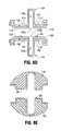
- FIG. 5 is a perspective view of another embodiment of an alignment spacer for use in connection with the manufacture of a matched pair of opposing jaw members in accordance with the present disclosure
- FIG. 6 is a perspective view of yet another embodiment of an alignment spacer for use in connection with the manufacture of a matched pair of opposing jaw members in accordance with the present disclosure
- FIG. 7 is a perspective view of still another embodiment of an alignment spacer for use in connection with the manufacture of a matched pair of opposing jaw members in accordance with the present disclosure
- FIGS. 8A through 8E show a schematic representation of a sequence of operations of a method of manufacturing a matched pair of opposing jaw members in accordance with an embodiment of the present disclosure
- FIGS. 9 and 10 are perspective views of portions of opposing jaw members, with parts separated, in accordance with an embodiment of the present disclosure.
- FIG. 11 is a perspective view of the matched pair of opposing jaw members of FIG. 3 , shown with the alignment spacer of FIG. 4 disposed in spaced relation therebetween, in accordance with an embodiment of the present disclosure
- FIG. 12 is a cross-sectional view of a matched pair of opposing jaw members disposed in a clamped engagement with the alignment spacer of FIG. 4 in accordance with an embodiment of the present disclosure
- FIG. 13 is a cross-sectional view of the matched pair of opposing jaw members of FIG. 12 shown with a bonding material disposed in bonding regions in accordance with an embodiment of the present disclosure.
- FIG. 14 is a cross-sectional view of the matched pair of opposing jaw members of FIG. 13 , shown without the alignment spacer, in accordance with an embodiment of the present disclosure.
- proximal refers to that portion of the apparatus, or component thereof, closer to the user and the term “distal” refers to that portion of the apparatus, or component thereof, farther from the user.
- Various embodiments of the present disclosure provide surgical instruments, e.g., surgical forceps, suitable for sealing, cauterizing, coagulating/desiccating and/or cutting vessels and vascular tissue.
- surgical instruments e.g., surgical forceps
- Embodiments of the presently-disclosed surgical instruments may be suitable for utilization in endoscopic surgical procedures and/or suitable for utilization in open surgical applications.
- Embodiments of the presently-disclosed end-effector assemblies include a pair of opposing jaw members.
- One or more of the jaw members include a support structure, an electrical lead, and a sealing plate coupled to the electrical lead.
- Embodiments of the presently-disclosed jaw members include an insulator member disposed between the support structure and the sealing plate.
- Embodiments of the present disclosure provide methods of manufacturing a matched pair of jaw members of an end-effector assembly.
- Embodiments of the presently-disclosed methods of manufacturing a matched pair of jaw members include setting a jaw gap and aligning the sealing plates in relation to one another.
- Various embodiments of the present disclosure provide an alignment spacer for use in connection with the manufacture of a matched pair of jaw members.
- Embodiments of the presently-disclosed alignment spacers are configured to align the sealing plates in relation to one another and also configured to set jaw gap and/or to set the tip bias of the jaw members.
- a surgical instrument generally identified as forceps 10 is shown for use in connection with endoscopic surgical procedures and includes a housing 20 , a handle assembly 30 , a rotatable assembly 80 , a trigger assembly 70 , and an end-effector assembly 100 including a pair of jaw members 110 and 120 .
- the jaw members 110 and 120 may be a matched pair.
- Forceps 10 may include additional, fewer, or different components than shown in FIG. 1 , depending upon a particular purpose or to achieve a desired result.
- Forceps 10 generally includes an elongated shaft 12 that defines a longitudinal axis “A-A”, and supports the end-effector assembly 100 .
- Shaft 12 defines a central lumen therethrough to facilitate translational movement of other components, e.g., to impart movement to the jaw members 110 and 120 .
- One or more components of the forceps 10 e.g., the housing 20 , the rotatable assembly 80 , the handle assembly 30 , the trigger assembly 70 , and/or the end-effector assembly 100 , may be adapted to mutually cooperate to grasp, seal and/or divide tissue, e.g., tubular vessels and vascular tissue.
- the end-effector assembly 100 is rotatable in either direction about the longitudinal axis “A-A” through rotation, either manually or otherwise, of the rotatable assembly 80 .
- a transverse axis “B-B” is shown in FIG. 2 .
- the transverse axis “B-B” is perpendicular or substantially perpendicular to the longitudinal axis “A-A”.
- End-effector assembly 100 may include any feature or combination of features of the jaw member embodiments disclosed herein.
- End-effector assembly 100 may be configured as a bilateral jaw assembly, i.e., both jaw members 110 and 120 move relative to one another.
- the forceps 10 may include a unilateral assembly, i.e., the end-effector assembly 100 may include a stationary jaw member, e.g., jaw member 120 , mounted in fixed relation to the shaft 12 and a pivoting jaw member, e.g., jaw member 110 , mounted about a pivot pin 103 coupled to the stationary jaw member.
- Jaw members 110 and 120 may be curved at various angles to facilitate manipulation of tissue and/or to provide enhanced line-of-sight for accessing targeted tissues.
- the shaft 12 has a distal end 16 configured to mechanically engage the end-effector assembly 100 .
- the proximal end 14 of the shaft 12 is received within the housing 20 or is otherwise engaged to the housing 20 , and connections relating thereto are disclosed in commonly-assigned U.S. Pat. No. 7,156,846 entitled “Vessel Sealer And Divider For Use With Small Trocars And Cannulas,” commonly-assigned U.S. Pat. No. 7,597,693 entitled “Vessel Sealer And Divider For Use With Small Trocars And Cannulas” and commonly-assigned U.S. Pat. No. 7,771,425 entitled “Vessel Sealer And Divider Having A Variable Jaw Clamping Mechanism.”
- Handle assembly 30 includes a fixed handle 50 and a movable handle 40 .
- Movable handle 40 of the handle assembly 30 is ultimately connected to a drive assembly (not shown).
- Applying force to move the movable handle 40 toward the fixed handle 50 pulls a drive sleeve or drive rod (not shown) proximally to impart movement to the jaw members 110 and 120 from an open position, wherein the jaw members 110 and 120 are disposed in spaced relation relative to one another, to a clamping or closed position, wherein the jaw members 110 and 120 cooperate to grasp tissue therebetween.
- Forceps 10 includes an electrosurgical cable 15 .
- Cable 15 may be formed from a suitable flexible, semi-rigid, or rigid cable, and may connect directly to a power generating source 28 .
- Cable 15 may be internally divided into one or more cable leads each of which transmits energy through their respective feed paths to the end-effector assembly 100 .
- Power generating source 28 may be any generator suitable for use with surgical devices, and may be configured to provide various frequencies of electromagnetic energy.
- Forceps 10 may alternatively be configured as a wireless device or battery-powered.
- jaw members 110 and 120 include an electrically-conductive tissue-engaging surface or sealing plate 112 and 122 , respectively, arranged in opposed relation relative to one another.
- Sealing plates 112 and 122 define longitudinally-extending elongated slots 125 a and 125 b , respectively.
- the shape and size of the sealing plates 112 and 122 may be varied from the configuration depicted in FIGS. 1 through 3 .
- Jaw member 120 includes a plurality of stop members 90 disposed on an inner-facing surface 123 of the sealing plate 122 .
- one or more stop members 90 may be disposed on an inner-facing surface 113 of the sealing plate 112 .
- Stop members 90 may be configured to facilitate and/or enhance the gripping and manipulation of tissue and/or configured to define the gap distance “G” ( FIG. 3 ) between the opposing jaw members 110 and 120 during the sealing of tissue.
- Stop members 90 may be disposed on or adjacent to one or both of the sealing plates 112 and 122 , and/or operatively associated with one or both jaw members 110 and 120 .
- Jaw members 110 and 120 include an outer housing 111 and 121 , respectively.
- Outer housings 111 and 121 may define a cavity (not shown) therein configured to at least partially encapsulate and/or securely engage the sealing plates 112 and 122 , respectively, and/or other jaw member components.
- the outer housings 111 and 121 may be made from an electrically and thermally insulating material, e.g., a temperature resistant plastic or a ceramic.
- Jaw members 110 and 120 include a support structure 118 and 119 , respectively, and an insulator member 134 and 144 , respectively.
- Support structures 118 and 119 may be formed from any suitable material or combination of materials, e.g., metallic material, plastic and the like, and may be formed by any suitable process, e.g., machining, stamping, electrical discharge machining (EDM), forging, casting, injection molding, metal injection molding (MIM), and/or fineblanking.
- metallic material that may be suitable include aluminum and alloys thereof, plated brass, stainless steel, stainless steel alloys, beryllium copper, etc.
- Insulator members 134 and 144 are disposed between the support structures 118 and 119 and the sealing plates 112 and 122 , respectively.
- Insulator members 134 and 144 generally include outer surfaces 107 and 109 , respectively.
- Insulator members 134 are configured to define knife channels 145 a and 145 b , respectively.
- the insulator members 134 and 144 include one or more boss members 117 and 127 , respectively, protruding from the outer surfaces 107 and 109 thereof, e.g., disposed on opposite sides of the knife channels 145 a and 145 b , respectively.
- the boss members 117 and 127 may be configured as single unitary structures.
- the boss members 117 and 127 may be configured as a plurality of separate, spaced-apart structures of any suitable configuration, e.g., a plurality of a regular or irregular geometric shape.
- the boss members 117 and 127 help to define bonding regions 116 and 126 , respectively, disposed between the insulator members 134 and 144 and the support structures 118 and 119 , respectively.
- a bonding material e.g., a high-temperature epoxy adhesive, is disposed in the bonding regions 116 and 126 .
- FIGS. 4 through 7 show embodiments of an alignment spacer for use in connection with the manufacture of a matched pair of jaw members 110 and 120 .
- Alignment spacer embodiments as described herein are configured for use to align the sealing plates 112 and 122 in relation with one another.
- the presently-disclosed alignment spacer is configured to facilitate aligning the slot 125 a and the knife channel 145 a of the first jaw member 110 and the slot 125 b and the knife channel 145 b of the second jaw member 120 in a direction along the longitudinal axis “A-A” of the end-effector assembly 100 and in a direction substantially transverse to the longitudinal axis “A-A”.
- FIG. 4 shows an alignment spacer 400 for use in connection with the manufacture of the matched pair of jaw members 110 and 120 .
- Alignment spacer 400 is configured to set the jaw gap (e.g., gap “G” disposed between the inner-facing surfaces of the jaw members 110 and 120 shown in FIGS. 3 and 14 ) and also configured to align the sealing plates 112 and 122 in relation to one another.
- Alignment spacer 400 may be formed from any suitable material or combination of materials, e.g., plastic, and may be formed by any suitable process, e.g., injection molding.
- Alignment spacer 400 generally includes a substrate 410 having a first surface 411 and a second surface 413 .
- the substrate 410 may have a generally rectangular shape.
- the substrate 410 depicted in FIG. 4 includes straight edges, other shapes including curves may be utilized.
- Substrate 410 may have any suitable height “H 1 ”.
- the alignment spacer 400 includes a plurality of alignment members 420 associated with the first surface 411 of the substrate 410 , and a plurality of alignment members 430 associated with the second surface 413 . Alignment members 420 and 430 may be configured to engage the knife channels 145 a and 145 b , respectively.
- FIG. 5 shows an alignment spacer 500 for use in connection with the manufacture of a matched pair of opposing jaw members in accordance with the present disclosure.
- Alignment spacer 500 is configured to set the tip bias of the jaw members 110 and 120 and also configured to align the sealing plates 112 and 122 in relation to one another.
- Alignment spacer 500 includes a substrate 510 having a first surface 511 and a second surface 513 . As shown in FIG. 5 , the substrate 510 has a first height “H 2 ” at its distal end 516 and a second height “H 3 ” at its proximal end 514 , resulting in a wedge-like shape, e.g., configured to set the tip bias of the jaw members 110 and 120 .
- FIG. 6 shows an alignment spacer 600 for use in connection with the manufacture of a matched pair of opposing jaw members in accordance with the present disclosure and includes a substrate 610 having a first surface 611 and a second surface 613 .
- Alignment spacer 600 is configured to set the jaw gap (e.g., gap “G” shown in FIGS. 3 and 14 ) and also configured to align the sealing plates 112 and 122 in relation to one another.
- Substrate 610 shown in FIG. 6 is similar to the substrate 410 of FIG. 4 , and further description thereof is omitted in the interests of brevity.
- a unitary alignment member 620 is associated with the first surface 611 of the substrate 610
- a unitary alignment member 630 is associated with the second surface 613 of the substrate 610 .
- This configuration may enhance the rigidity and/or durability of the alignment spacer 600 .
- the unitary alignment members 620 and 630 have an elongated bar-like shape, which may increase ease of manufacture and/or inspection, and which may improve usability, e.g., depending on the configuration of the knife channels 145 a and 145 b.
- an alignment spacer 700 for use in connection with the manufacture of a matched pair of opposing jaw members in accordance with the present disclosure is shown and includes a substrate 710 .
- an alignment member 720 is associated with a first surface 711 of the substrate 710
- an alignment member 730 is associated with a second surface 713 of the substrate 710 .
- Substrate 710 is similar to the substrate 410 shown in FIG. 4 , and further description thereof is omitted in the interests of brevity.
- Alignment members 720 and 730 shown in FIG. 7 are similar to the elongated bar-like shaped alignment members 620 and 630 of FIG. 7 , except for the curved, cutout portions 721 and 731 .
- FIGS. 8A through 8E schematically illustrates a series of operations according to a method of manufacturing a matched pair of opposing jaw members.
- One or more of the operations depicted in the illustrative embodiment of FIGS. 8A through 8E may be performed in combination and in a different order than presented herein without departing from the scope of the disclosure.
- the operations which are described in more detail below, generally involve the depositing of a plurality of stop members 90 onto the sealing plate 122 ( FIG. 8B ), the coupling of electrical leads 104 and 106 to the sealing plates 112 and 122 , respectively ( FIG. 8C ), the coupling of the insulator members 134 and 144 to the sealing plates 112 and 122 , respectively ( FIG. 8D ), and the placing of a bonding material 60 onto one or more surfaces of the inner side of the support structures 118 and 119 ( FIG. 8E ).
- Sealing plates 112 and 122 as shown in FIGS. 8A through 8C , have an inner-facing surface 113 and 123 , respectively, and an outer surface 114 and 124 , respectively.
- Sealing plates 112 and 122 may be formed from any suitable material or combination of materials, e.g., metallic material, and may be formed by any suitable process, e.g., machining, stamping, metal injection molding (MIM), and/or fineblanking.
- the shape and size of the sealing plates 112 and 122 may be varied from the configuration depicted in FIGS. 8A through 8C .
- a plurality of stop members 90 is deposited onto the inner-facing surface 123 of the sealing plate 122 .
- One or more stop members 90 may be deposited onto either one or both of the sealing plates 112 and 122 .
- a plurality of stop members 90 may be deposited onto one of the sealing plates (e.g., sealing plate 122 ) prior to the coupling of the insulator members 134 and 144 to the sealing plates 112 and 122 , respectively.
- Stop members 90 may be made from any suitable insulative material, e.g., peek, nylon and/or ceramic.
- stop member embodiments as well as various manufacturing and assembling processes for attaching and/or affixing the stop members 90 to the sealing plates 112 and 122 are described in commonly-assigned International Publication No. WO 2002/080796 filed on Apr. 6, 2001, entitled “Vessel Sealer And Divider With Non-Conductive Stop Members.”
- Electrical leads 104 and 106 are coupled to the outer surfaces 114 and 124 of the sealing plates 112 and 122 , respectively. Electrical leads 104 and 106 may be electrically-coupled to the sealing plates 112 and 122 by any suitable manner of electrical connection, e.g., soldering, welding, or laser welding. One or more electrical leads may be electrically-coupled by any suitable manner to either one or both of the sealing plates 112 and 122 .
- Insulator members 134 and 144 may include any of a variety of suitable non-electrically conductive materials such as polymeric materials, e.g., plastics, and/or other insulative materials, and may be formed by any suitable process.
- Longitudinally-extending knife channels 145 a and 145 b defined by the insulator members 134 and 144 may be configured to align with the longitudinally-extending slots 125 a and 125 b defined by the sealing plates 112 and 122 , respectively, to permit longitudinal reciprocation of a knife blade (not shown).
- Insulator members 134 and 144 may be coupled to one or more surfaces of the sealing plates 112 and 122 , respectively, by any suitable process. In some embodiments, the insulator members 134 and 144 are overmolded onto the sealing plates 112 and 122 , respectively. Alternatively, the insulator members 134 and 144 may be formed by injection molding, and may be adhesively-attached to the sealing plates 112 and 122 , respectively. A variety of different configurations of stop members 90 may be deposited onto either one or both of the sealing plates 112 and 122 , e.g., prior to and/or after the coupling of the insulator members 134 and 144 to the sealing plates 112 and 122 , respectively. In some embodiments, as shown for example in FIG.
- the insulator members 134 and 144 include one or more boss members 117 and 127 , respectively, protruding from the outer surfaces 107 and 109 , respectively.
- the boss members 117 and 127 help to define bonding regions 116 and 126 , respectively, disposed between the insulator members 134 and 144 and the support structures 118 and 119 , respectively.
- FIGS. 9 and 10 show the support structures 118 and 119 disposed in spaced relation to the insulator members 134 and 144 , respectively, and in an aligned configuration relative to one another.
- a bonding material 60 may be placed within the bonding regions 116 and 126 prior to the positioning of the support structures 118 and 119 into mating engagement with the insulator members 134 and 144 , respectively.
- the bonding material 60 may be placed on one or more inner-facing surfaces of the support structures 118 and 119 as shown in FIG. 8E . It is to be understood that the bonding material 60 may be deposited onto one or more surfaces of the support structures 118 and 119 and/or one or more surfaces of the insulator members 134 and 144 .
- the bonding material 60 may be placed (e.g., by injection) into the bonding regions 116 and 126 after the positioning of the support structures 118 and 119 into mating engagement with the insulator members 134 and 144 , respectively.
- FIG. 11 shows the opposing jaw members 110 and 120 with the alignment spacer 400 disposed in spaced relation therebetween.
- the plurality of alignment members 420 protruding from the first surface 411 of the substrate 410 of the alignment spacer 400 are configured to engage with the knife channel 145 a of the jaw member 110
- the alignment members 430 protruding from the second surface 413 of the substrate 410 are configured to engage with the knife channel 145 b of the jaw member 120 .
- the jaw members 110 and 120 may be coupled to one another in any suitable manner.
- the jaw members 110 and 120 may be pivotably mounted with respect to one another, e.g., mounted about a pivot pin 103 ( FIGS. 1 and 2 ).
- the support structures 118 and 119 may be positioned into mating engagement with the insulator members 134 and 144 , respectively, prior to the depositing of the bonding material 60 within the bonding regions 116 and 126 .
- a holding fixture (not shown) may be provided for retaining the support structures 118 and 119 in mating engagement with the insulator members 134 and 144 , respectively, e.g., during the placing of the bonding material 60 into the bonding regions 116 and 126 and/or the curing of the bonding material 60 , and/or to facilitate other operations, e.g., the coupling of the first jaw member 110 to the second jaw member 120 .
- FIG. 13 shows the support structures 118 and 119 disposed in mating engagement with the insulator members 134 and 144 , respectively, with the bonding material 60 disposed within the bonding regions 116 and 126 , and the sealing plates 112 and 122 disposed in a clamped engagement with the alignment spacer 400 .
- the support structures 118 and 119 , the insulator members 134 and 144 , and/or the sealing plates 112 and 122 may be at least partially encapsulated by outer insulative housings (e.g., outer housing 111 and 121 shown in FIG. 2 ) by way of a subsequent overmolding process.
- outer insulative housings e.g., outer housing 111 and 121 shown in FIG. 2
- FIG. 14 the matched pair of opposing jaw members 110 and 120 , assembled in accordance with the presently-disclosed methods of manufacturing a matched pair of opposing jaw members, is shown without the alignment spacer 400 of FIG. 14 .
- a method of manufacturing a matched pair of opposing jaw members 110 and 120 of an end-effector assembly 100 includes: assembling a first jaw member 110 having a knife channel 125 a , 145 a ; assembling a second jaw member 120 having a knife channel 145 b ; and setting a jaw gap “G” and aligning a sealing plate 112 of the first jaw member 110 and a sealing plate 122 of the second jaw member 120 in relation to one another by bringing the first jaw member 110 and the second jaw member 120 into clamped engagement with an alignment spacer 400 .
- the alignment spacer 400 is configured to engage the knife channel 145 a of the first jaw member 110 and the knife channel 145 b of the second jaw member 120 .
- the method also includes coupling the first jaw member 110 to the second jaw member 120 .
- aligning the sealing plates 112 and 122 in relation to one another includes aligning the knife channel 145 a of the first jaw member 110 and the knife channel 145 b of the second jaw member 120 in a direction along the longitudinal axis “A-A” of the end-effector assembly 100 and in a direction substantially transverse to the longitudinal axis “A-A”.
- assembling the first jaw member 110 includes electrically-coupling an electrical lead 104 to the first sealing plate 112 and overmolding a first insulator member 134 onto the first sealing plate 112 .
- assembling the first jaw member 110 may further include coupling a first support structure 118 to the first insulator member 134 .
- coupling the first support structure 118 to the first insulator member 134 includes depositing a bonding material 60 within a bonding region 116 disposed between the first insulator member 134 and the first support structure 118 .
- one or more boss members 117 associated with the first insulator member 134 and/or one or one or more boss members 127 associated with the second insulator member 144 may be configured to be crushable or collapsible or otherwise deformable to allow the alignment spacer 400 to set the jaw gap (e.g., gap “G” disposed between the inner-facing surfaces of the jaw members 110 and 120 shown in FIGS. 3 and 14 ).
- the height “H 4 ” of the bonding region 116 may vary depending on the deformation of one or more boss members 117
- the height “H 5 ” ( FIG. 11 ) of the bonding region 126 may vary depending on the deformation of one or more boss members 127 .
- a method of manufacturing a matched pair of opposing jaw members 110 and 120 of an end-effector assembly 100 includes assembling a first jaw member 110 , including coupling an electrical lead 104 to a first sealing plate 112 , coupling (e.g., overmolding) a first insulator member 134 onto the first sealing plate 112 , and coupling a first support structure 118 to the first insulator member 134 .
- the method includes assembling a second jaw member 120 , including coupling (e.g., overmolding) a second insulator member 144 onto a second sealing plate 122 , and coupling a second support structure 119 to the second insulator member 144 .
- the method also includes setting a jaw gap “G” and aligning the first sealing plate 112 and the second sealing plate 122 in relation to one another by bringing the first jaw member 110 and the second jaw member 120 into clamped engagement with an alignment spacer 400 , and movably coupling the first jaw member 110 to the second jaw member 120 while in clamped engagement with the alignment spacer 400 .
- the alignment spacer 400 is configured to engage a first knife channel 145 a defined by the first insulator member 134 and a second knife channel 145 b defined by the second insulator member 144 .
- aligning the first sealing plate 112 and the second sealing plate 122 in relation to one another includes aligning an elongated slot 125 a of the first sealing plate 112 and an elongated slot 125 b of the second sealing plate 122 in a direction along a longitudinal axis “A-A” of the end-effector assembly 100 and in a direction substantially transverse to the longitudinal axis “A-A”.
- bringing the first jaw member 110 and the second jaw member 120 into clamped engagement with the alignment spacer 400 aligns the slot 125 a and the knife channel 145 a of the first jaw member 110 and the slot 125 b and the knife channel 145 b of the second jaw member 120 in a direction along the longitudinal axis “A-A” of the end-effector assembly 100 and in a direction substantially transverse to the longitudinal axis “A-A”.
- a bonding material 60 may be placed on the first support structure 118 and/or the second support structure 119 .
- a bonding material 60 may be placed on a support structure (e.g., first support structure 118 ) and the support structure coupled to an insulator member (e.g., first insulator member 134 ), after which the alignment spacer 400 may be added with the other jaw member (e.g., second jaw member 120 ).
- the matched pair of opposing jaw members 110 and 120 may be pivotably mounted about a pin configured to permanently join the jaw members. In accordance with any one of the above-described methods, the matched pair of opposing jaw members 110 and 120 may be welded together.
- the above-described methods of manufacturing a pair of opposing jaw members of an end-effector assembly may also include releasing the alignment spacer 400 from a matched pair of opposing jaw members 110 and 120 , e.g., after releasing the matched pair of opposing jaw members 110 and 120 from a holding fixture.
- the alignment spacer 400 may be released and removed at any suitable point.
- jaw gap, tip bias, and seal-plate alignment may be set by the use of an alignment spacer in conjunction with the use of one or more (deformable) boss members associated with the first insulator member and/or one or more (deformable) boss members associated with the second insulator member.
- the above-described end-effector assembly embodiments including any combination of features of the above-described matched pair of opposing jaw members may utilize jaw member components of varied geometries, e.g., lengths and curvatures, such that variously-configured matched pairs of opposing jaw members may be fabricated and assembled into various end-effector configurations, e.g., depending upon design of specialized surgical instruments.
- the above-described surgical instrument embodiments may also be configured to work with robotic surgical systems and what is commonly referred to as “Telesurgery.”
- Such systems employ various robotic elements to assist the surgeon in the operating theater and allow remote operation (or partial remote operation) of surgical instrumentation.
- Various robotic arms, gears, cams, pulleys, electric and mechanical motors, etc. may be employed for this purpose and may be designed with a robotic surgical system to assist the surgeon during the course of an operation or treatment.
- Such robotic systems may include, remotely steerable systems, automatically flexible surgical systems, remotely flexible surgical systems, remotely articulating surgical systems, wireless surgical systems, modular or selectively configurable remotely operated surgical systems, etc.
- the robotic surgical systems may be employed with one or more consoles that are next to the operating theater or located in a remote location.
- one team of surgeons or nurses may prep the patient for surgery and configure the robotic surgical system with one or more of the instruments disclosed herein while another surgeon (or group of surgeons) remotely controls the instruments via the robotic surgical system.
- a highly skilled surgeon may perform multiple operations in multiple locations without leaving his/her remote console which can be both economically advantageous and a benefit to the patient or a series of patients.
- the robotic arms of the surgical system are typically coupled to a pair of master handles by a controller.
- the handles can be moved by the surgeon to produce a corresponding movement of the working ends of any type of surgical instrument (e.g., end effectors, graspers, knifes, scissors, etc.) which may complement the use of one or more of the embodiments described herein.
- the movement of the master handles may be scaled so that the working ends have a corresponding movement that is different, smaller or larger, than the movement performed by the operating hands of the surgeon.
- the scale factor or gearing ratio may be adjustable so that the operator can control the resolution of the working ends of the surgical instrument(s).
- the master handles may include various sensors to provide feedback to the surgeon relating to various tissue parameters or conditions, e.g., tissue resistance due to manipulation, cutting or otherwise treating, pressure by the instrument onto the tissue, tissue temperature, tissue impedance, etc. As can be appreciated, such sensors provide the surgeon with enhanced tactile feedback simulating actual operating conditions.
- the master handles may also include a variety of different actuators for delicate tissue manipulation or treatment further enhancing the surgeon's ability to mimic actual operating conditions.
Abstract
A method of manufacturing a matched pair of opposing jaw members of an end-effector assembly includes assembling a first jaw member having a knife channel, assembling a second jaw member having a knife channel, setting a jaw gap and aligning a first sealing plate of the first jaw member and a second sealing plate of the second jaw member in relation to one another by bringing the first jaw member and the second jaw member into clamped engagement with an alignment spacer. The alignment spacer is configured to engage the knife channel of the first jaw member and the knife channel of the second jaw member. The method also includes coupling the first jaw member to the second jaw member.
Description
The present application claims the benefit of and priority to U.S. Provisional Application Ser. No. 61/980,742, filed on Apr. 17, 2014, the entire contents of which are incorporated herein by reference.
1. Technical Field
The present disclosure relates to surgical instruments. More particularly, the present disclosure relates to end-effector assemblies for use in surgical instruments and methods of manufacturing a pair of jaw members of an end-effector assembly.
2. Discussion of Related Art
Bipolar electrosurgical forceps have an end-effector assembly with electrodes on the inner, opposing surfaces of pivotally movable jaw members. The electrodes are electrically coupled to an electrosurgical generator, with the electrode on one jaw member actively delivering electrosurgical energy and the electrode on the other jaw member functioning as a return, thereby creating an electrical circuit through tissue grasped by the jaw members.
Tissue grasped by the jaw members can be treated to different degrees (e.g., cauterized, coagulated, desiccated or sealed) depending on the intensity, frequency and duration of the electrosurgical energy applied by the electrodes. The effectiveness of the electrosurgical energy on the tissue is affected by mechanical factors such as the pressure applied to the tissue when grasped by the jaw members and the gap distance between the electrodes.
Predictability in such mechanical factors can be provided by meeting specific tolerance requirements when manufacturing the end-effector assembly of the electrosurgical forceps. It would be desirable to develop manufacturing methods for end-effector assemblies to meet tolerance requirements such as gap tolerances, alignment of the jaw members and the like.
End-effector assemblies that meet design tolerance requirements are provided by the manufacturing processes described herein.
According to an aspect of the present disclosure, a method of manufacturing a pair of opposing jaw members of an end-effector assembly includes assembling a first jaw member having a knife channel, assembling a second jaw member having a knife channel, setting a jaw gap and aligning a first sealing plate of the first jaw member and a second sealing plate of the second jaw member in relation to one another by bringing the first jaw member and the second jaw member into a clamped engagement with an alignment spacer. The alignment spacer is configured to engage the knife channel of the first jaw member and the knife channel of the second jaw member. The method also includes coupling the first jaw member to the second jaw member.
According to another aspect of the present disclosure, a method of manufacturing a pair of opposing jaw members of an end-effector assembly is provided. The method includes the initial steps of assembling a first jaw member, including: coupling an electrical lead to a first sealing plate; overmolding a first insulator member onto the first sealing plate; and coupling a first support structure to the first insulator member; and assembling a second jaw member, including: overmolding a second insulator member onto a second sealing plate; and coupling a second support structure to the second insulator member. The method also includes setting a jaw gap and aligning the first sealing plate and the second sealing plate in relation to one another by bringing the first jaw member and the second jaw member into clamped engagement with an alignment spacer configured to engage a first knife channel defined by the first insulator member and a second knife channel defined by the second insulator member; and movably coupling the first jaw member to the second jaw member while in clamped engagement with the alignment spacer.
In any one of the preceding aspects, the alignment spacer may be configured to set a tip bias of the first jaw member and the second jaw member.
In any one of the preceding aspects, the method also includes releasing the alignment spacer from the pair of opposing jaw members.
Objects and features of the end-effector assemblies for use in surgical instruments and methods of manufacturing a pair of jaw members of an end-effector assembly of the present disclosure will become apparent to those of ordinary skill in the art when descriptions of various embodiments thereof are read with reference to the accompanying drawings, of which:
Hereinafter, embodiments of end-effector assemblies for use in surgical instruments and methods of manufacturing a pair of jaw members of an end-effector assembly of the present disclosure are described with reference to the accompanying drawings. Like reference numerals may refer to similar or identical elements throughout the description of the figures. As shown in the drawings and as used in this description, and as is traditional when referring to relative positioning on an object, the term “proximal” refers to that portion of the apparatus, or component thereof, closer to the user and the term “distal” refers to that portion of the apparatus, or component thereof, farther from the user.
This description may use the phrases “in an embodiment,” “in embodiments,” “in some embodiments,” or “in other embodiments,” which may each refer to one or more of the same or different embodiments in accordance with the present disclosure.
Various embodiments of the present disclosure provide surgical instruments, e.g., surgical forceps, suitable for sealing, cauterizing, coagulating/desiccating and/or cutting vessels and vascular tissue. Embodiments of the presently-disclosed surgical instruments may be suitable for utilization in endoscopic surgical procedures and/or suitable for utilization in open surgical applications.
Various embodiments of the present disclosure provide end-effector assemblies for use in surgical instruments. Embodiments of the presently-disclosed end-effector assemblies include a pair of opposing jaw members. One or more of the jaw members include a support structure, an electrical lead, and a sealing plate coupled to the electrical lead. Embodiments of the presently-disclosed jaw members include an insulator member disposed between the support structure and the sealing plate.
Various embodiments of the present disclosure provide methods of manufacturing a matched pair of jaw members of an end-effector assembly. Embodiments of the presently-disclosed methods of manufacturing a matched pair of jaw members include setting a jaw gap and aligning the sealing plates in relation to one another.
Various embodiments of the present disclosure provide an alignment spacer for use in connection with the manufacture of a matched pair of jaw members. Embodiments of the presently-disclosed alignment spacers are configured to align the sealing plates in relation to one another and also configured to set jaw gap and/or to set the tip bias of the jaw members.
In FIG. 1 , a surgical instrument generally identified as forceps 10 is shown for use in connection with endoscopic surgical procedures and includes a housing 20, a handle assembly 30, a rotatable assembly 80, a trigger assembly 70, and an end-effector assembly 100 including a pair of jaw members 110 and 120. In one embodiment, the jaw members 110 and 120 may be a matched pair. Forceps 10 may include additional, fewer, or different components than shown in FIG. 1 , depending upon a particular purpose or to achieve a desired result. Forceps 10 generally includes an elongated shaft 12 that defines a longitudinal axis “A-A”, and supports the end-effector assembly 100. Shaft 12 defines a central lumen therethrough to facilitate translational movement of other components, e.g., to impart movement to the jaw members 110 and 120. One or more components of the forceps 10, e.g., the housing 20, the rotatable assembly 80, the handle assembly 30, the trigger assembly 70, and/or the end-effector assembly 100, may be adapted to mutually cooperate to grasp, seal and/or divide tissue, e.g., tubular vessels and vascular tissue.
As depicted in FIG. 1 , the end-effector assembly 100 is rotatable in either direction about the longitudinal axis “A-A” through rotation, either manually or otherwise, of the rotatable assembly 80. A transverse axis “B-B” is shown in FIG. 2 . The transverse axis “B-B” is perpendicular or substantially perpendicular to the longitudinal axis “A-A”. End-effector assembly 100 may include any feature or combination of features of the jaw member embodiments disclosed herein.
End-effector assembly 100 may be configured as a bilateral jaw assembly, i.e., both jaw members 110 and 120 move relative to one another. Alternatively, the forceps 10 may include a unilateral assembly, i.e., the end-effector assembly 100 may include a stationary jaw member, e.g., jaw member 120, mounted in fixed relation to the shaft 12 and a pivoting jaw member, e.g., jaw member 110, mounted about a pivot pin 103 coupled to the stationary jaw member. Jaw members 110 and 120 may be curved at various angles to facilitate manipulation of tissue and/or to provide enhanced line-of-sight for accessing targeted tissues.
As shown in FIG. 1 , the shaft 12 has a distal end 16 configured to mechanically engage the end-effector assembly 100. The proximal end 14 of the shaft 12 is received within the housing 20 or is otherwise engaged to the housing 20, and connections relating thereto are disclosed in commonly-assigned U.S. Pat. No. 7,156,846 entitled “Vessel Sealer And Divider For Use With Small Trocars And Cannulas,” commonly-assigned U.S. Pat. No. 7,597,693 entitled “Vessel Sealer And Divider For Use With Small Trocars And Cannulas” and commonly-assigned U.S. Pat. No. 7,771,425 entitled “Vessel Sealer And Divider Having A Variable Jaw Clamping Mechanism.”
Handle assembly 30 includes a fixed handle 50 and a movable handle 40. Movable handle 40 of the handle assembly 30 is ultimately connected to a drive assembly (not shown). Applying force to move the movable handle 40 toward the fixed handle 50 pulls a drive sleeve or drive rod (not shown) proximally to impart movement to the jaw members 110 and 120 from an open position, wherein the jaw members 110 and 120 are disposed in spaced relation relative to one another, to a clamping or closed position, wherein the jaw members 110 and 120 cooperate to grasp tissue therebetween.
As shown in FIGS. 1 through 3 , jaw members 110 and 120 include an electrically-conductive tissue-engaging surface or sealing plate 112 and 122, respectively, arranged in opposed relation relative to one another. Sealing plates 112 and 122 define longitudinally-extending elongated slots 125 a and 125 b, respectively. The shape and size of the sealing plates 112 and 122 may be varied from the configuration depicted in FIGS. 1 through 3 .
In some embodiments, the insulator members 134 and 144 include one or more boss members 117 and 127, respectively, protruding from the outer surfaces 107 and 109 thereof, e.g., disposed on opposite sides of the knife channels 145 a and 145 b, respectively. In some embodiments, as shown for example in FIG. 9 , the boss members 117 and 127 may be configured as single unitary structures. Alternatively, the boss members 117 and 127 may be configured as a plurality of separate, spaced-apart structures of any suitable configuration, e.g., a plurality of a regular or irregular geometric shape. The boss members 117 and 127 help to define bonding regions 116 and 126, respectively, disposed between the insulator members 134 and 144 and the support structures 118 and 119, respectively. As described later in this description, a bonding material, e.g., a high-temperature epoxy adhesive, is disposed in the bonding regions 116 and 126.
As shown in FIG. 6 , a unitary alignment member 620 is associated with the first surface 611 of the substrate 610, and a unitary alignment member 630 is associated with the second surface 613 of the substrate 610. This configuration may enhance the rigidity and/or durability of the alignment spacer 600. As shown in FIG. 6 , the unitary alignment members 620 and 630 have an elongated bar-like shape, which may increase ease of manufacture and/or inspection, and which may improve usability, e.g., depending on the configuration of the knife channels 145 a and 145 b.
In FIG. 7 , an alignment spacer 700 for use in connection with the manufacture of a matched pair of opposing jaw members in accordance with the present disclosure is shown and includes a substrate 710. As shown in FIG. 7 , an alignment member 720 is associated with a first surface 711 of the substrate 710, and an alignment member 730 is associated with a second surface 713 of the substrate 710. Substrate 710 is similar to the substrate 410 shown in FIG. 4 , and further description thereof is omitted in the interests of brevity. Alignment members 720 and 730 shown in FIG. 7 are similar to the elongated bar-like shaped alignment members 620 and 630 of FIG. 7 , except for the curved, cutout portions 721 and 731.
A plurality of stop members 90, as shown in FIG. 8B , is deposited onto the inner-facing surface 123 of the sealing plate 122. One or more stop members 90 may be deposited onto either one or both of the sealing plates 112 and 122. In some embodiments, a plurality of stop members 90 may be deposited onto one of the sealing plates (e.g., sealing plate 122) prior to the coupling of the insulator members 134 and 144 to the sealing plates 112 and 122, respectively. Stop members 90 may be made from any suitable insulative material, e.g., peek, nylon and/or ceramic. Examples of stop member embodiments as well as various manufacturing and assembling processes for attaching and/or affixing the stop members 90 to the sealing plates 112 and 122 are described in commonly-assigned International Publication No. WO 2002/080796 filed on Apr. 6, 2001, entitled “Vessel Sealer And Divider With Non-Conductive Stop Members.”
Electrical leads 104 and 106, as shown in FIG. 8C , are coupled to the outer surfaces 114 and 124 of the sealing plates 112 and 122, respectively. Electrical leads 104 and 106 may be electrically-coupled to the sealing plates 112 and 122 by any suitable manner of electrical connection, e.g., soldering, welding, or laser welding. One or more electrical leads may be electrically-coupled by any suitable manner to either one or both of the sealing plates 112 and 122.
In some embodiments, as shown in FIG. 12 , the support structures 118 and 119 may be positioned into mating engagement with the insulator members 134 and 144, respectively, prior to the depositing of the bonding material 60 within the bonding regions 116 and 126. A holding fixture (not shown) may be provided for retaining the support structures 118 and 119 in mating engagement with the insulator members 134 and 144, respectively, e.g., during the placing of the bonding material 60 into the bonding regions 116 and 126 and/or the curing of the bonding material 60, and/or to facilitate other operations, e.g., the coupling of the first jaw member 110 to the second jaw member 120.
In some embodiments, the support structures 118 and 119, the insulator members 134 and 144, and/or the sealing plates 112 and 122 may be at least partially encapsulated by outer insulative housings (e.g., outer housing 111 and 121 shown in FIG. 2 ) by way of a subsequent overmolding process.
In FIG. 14 , the matched pair of opposing jaw members 110 and 120, assembled in accordance with the presently-disclosed methods of manufacturing a matched pair of opposing jaw members, is shown without the alignment spacer 400 of FIG. 14 .
In accordance with an embodiment of the present disclosure, a method of manufacturing a matched pair of opposing jaw members 110 and 120 of an end-effector assembly 100 includes: assembling a first jaw member 110 having a knife channel 125 a, 145 a; assembling a second jaw member 120 having a knife channel 145 b; and setting a jaw gap “G” and aligning a sealing plate 112 of the first jaw member 110 and a sealing plate 122 of the second jaw member 120 in relation to one another by bringing the first jaw member 110 and the second jaw member 120 into clamped engagement with an alignment spacer 400. The alignment spacer 400 is configured to engage the knife channel 145 a of the first jaw member 110 and the knife channel 145 b of the second jaw member 120. The method also includes coupling the first jaw member 110 to the second jaw member 120.
In some embodiments of the above-described method of manufacturing a matched pair of opposing jaw members 110 and 120, aligning the sealing plates 112 and 122 in relation to one another includes aligning the knife channel 145 a of the first jaw member 110 and the knife channel 145 b of the second jaw member 120 in a direction along the longitudinal axis “A-A” of the end-effector assembly 100 and in a direction substantially transverse to the longitudinal axis “A-A”.
In some embodiments, assembling the first jaw member 110 includes electrically-coupling an electrical lead 104 to the first sealing plate 112 and overmolding a first insulator member 134 onto the first sealing plate 112. In some embodiments, assembling the first jaw member 110 may further include coupling a first support structure 118 to the first insulator member 134. In some embodiments, coupling the first support structure 118 to the first insulator member 134 includes depositing a bonding material 60 within a bonding region 116 disposed between the first insulator member 134 and the first support structure 118.
In some embodiments, one or more boss members 117 associated with the first insulator member 134 and/or one or one or more boss members 127 associated with the second insulator member 144 may be configured to be crushable or collapsible or otherwise deformable to allow the alignment spacer 400 to set the jaw gap (e.g., gap “G” disposed between the inner-facing surfaces of the jaw members 110 and 120 shown in FIGS. 3 and 14 ). In turn, the height “H4” of the bonding region 116 may vary depending on the deformation of one or more boss members 117, and/or the height “H5” (FIG. 11 ) of the bonding region 126 may vary depending on the deformation of one or more boss members 127.
In accordance with an embodiment of the present disclosure, a method of manufacturing a matched pair of opposing jaw members 110 and 120 of an end-effector assembly 100 includes assembling a first jaw member 110, including coupling an electrical lead 104 to a first sealing plate 112, coupling (e.g., overmolding) a first insulator member 134 onto the first sealing plate 112, and coupling a first support structure 118 to the first insulator member 134. The method includes assembling a second jaw member 120, including coupling (e.g., overmolding) a second insulator member 144 onto a second sealing plate 122, and coupling a second support structure 119 to the second insulator member 144. The method also includes setting a jaw gap “G” and aligning the first sealing plate 112 and the second sealing plate 122 in relation to one another by bringing the first jaw member 110 and the second jaw member 120 into clamped engagement with an alignment spacer 400, and movably coupling the first jaw member 110 to the second jaw member 120 while in clamped engagement with the alignment spacer 400. The alignment spacer 400 is configured to engage a first knife channel 145 a defined by the first insulator member 134 and a second knife channel 145 b defined by the second insulator member 144.
In accordance with embodiments of the above-described methods of manufacturing a matched pair of opposing jaw members 110 and 120, aligning the first sealing plate 112 and the second sealing plate 122 in relation to one another includes aligning an elongated slot 125 a of the first sealing plate 112 and an elongated slot 125 b of the second sealing plate 122 in a direction along a longitudinal axis “A-A” of the end-effector assembly 100 and in a direction substantially transverse to the longitudinal axis “A-A”. In some embodiments, bringing the first jaw member 110 and the second jaw member 120 into clamped engagement with the alignment spacer 400 aligns the slot 125 a and the knife channel 145 a of the first jaw member 110 and the slot 125 b and the knife channel 145 b of the second jaw member 120 in a direction along the longitudinal axis “A-A” of the end-effector assembly 100 and in a direction substantially transverse to the longitudinal axis “A-A”.
In accordance with any one of the above-described methods of manufacturing a matched pair of opposing jaw members 110 and 120 of an end-effector assembly 100, a bonding material 60 may be placed on the first support structure 118 and/or the second support structure 119. In some embodiments, a bonding material 60 may be placed on a support structure (e.g., first support structure 118) and the support structure coupled to an insulator member (e.g., first insulator member 134), after which the alignment spacer 400 may be added with the other jaw member (e.g., second jaw member 120). In accordance with any one of the above-described methods, the matched pair of opposing jaw members 110 and 120 may be pivotably mounted about a pin configured to permanently join the jaw members. In accordance with any one of the above-described methods, the matched pair of opposing jaw members 110 and 120 may be welded together.
The above-described methods of manufacturing a pair of opposing jaw members of an end-effector assembly may also include releasing the alignment spacer 400 from a matched pair of opposing jaw members 110 and 120, e.g., after releasing the matched pair of opposing jaw members 110 and 120 from a holding fixture. In accordance with any one of the above-described methods, the alignment spacer 400 may be released and removed at any suitable point.
The above-described methods of manufacturing a pair of opposing jaw members may utilize sealing plates and/or support structures fabricated with low manufacturing tolerances, thereby reducing costs, wherein jaw gap, tip bias, and seal-plate alignment may be set by the use of an alignment spacer in conjunction with the use of one or more (deformable) boss members associated with the first insulator member and/or one or more (deformable) boss members associated with the second insulator member.
The above-described end-effector assembly embodiments including any combination of features of the above-described matched pair of opposing jaw members may utilize jaw member components of varied geometries, e.g., lengths and curvatures, such that variously-configured matched pairs of opposing jaw members may be fabricated and assembled into various end-effector configurations, e.g., depending upon design of specialized surgical instruments.
The above-described surgical instrument embodiments may also be configured to work with robotic surgical systems and what is commonly referred to as “Telesurgery.” Such systems employ various robotic elements to assist the surgeon in the operating theater and allow remote operation (or partial remote operation) of surgical instrumentation. Various robotic arms, gears, cams, pulleys, electric and mechanical motors, etc. may be employed for this purpose and may be designed with a robotic surgical system to assist the surgeon during the course of an operation or treatment. Such robotic systems may include, remotely steerable systems, automatically flexible surgical systems, remotely flexible surgical systems, remotely articulating surgical systems, wireless surgical systems, modular or selectively configurable remotely operated surgical systems, etc.
The robotic surgical systems may be employed with one or more consoles that are next to the operating theater or located in a remote location. In this instance, one team of surgeons or nurses may prep the patient for surgery and configure the robotic surgical system with one or more of the instruments disclosed herein while another surgeon (or group of surgeons) remotely controls the instruments via the robotic surgical system. As can be appreciated, a highly skilled surgeon may perform multiple operations in multiple locations without leaving his/her remote console which can be both economically advantageous and a benefit to the patient or a series of patients.
The robotic arms of the surgical system are typically coupled to a pair of master handles by a controller. The handles can be moved by the surgeon to produce a corresponding movement of the working ends of any type of surgical instrument (e.g., end effectors, graspers, knifes, scissors, etc.) which may complement the use of one or more of the embodiments described herein. The movement of the master handles may be scaled so that the working ends have a corresponding movement that is different, smaller or larger, than the movement performed by the operating hands of the surgeon. The scale factor or gearing ratio may be adjustable so that the operator can control the resolution of the working ends of the surgical instrument(s).
The master handles may include various sensors to provide feedback to the surgeon relating to various tissue parameters or conditions, e.g., tissue resistance due to manipulation, cutting or otherwise treating, pressure by the instrument onto the tissue, tissue temperature, tissue impedance, etc. As can be appreciated, such sensors provide the surgeon with enhanced tactile feedback simulating actual operating conditions. The master handles may also include a variety of different actuators for delicate tissue manipulation or treatment further enhancing the surgeon's ability to mimic actual operating conditions.
Although embodiments have been described in detail with reference to the accompanying drawings for the purpose of illustration and description, it is to be understood that the disclosed processes and apparatus are not to be construed as limited thereby. It will be apparent to those of ordinary skill in the art that various modifications to the foregoing embodiments may be made without departing from the scope of the disclosure.
Claims (19)
1. A method of manufacturing a pair of opposing jaw members of an end-effector assembly, comprising:
assembling a first jaw member having a knife channel,
assembling a second jaw member having a knife channel,
setting a jaw gap and aligning a first sealing plate of the first jaw member and a second sealing plate of the second jaw member in relation to one another by bringing the first jaw member and the second jaw member into clamped engagement with an alignment spacer, the alignment spacer configured to engage the knife channel of the first jaw member and the knife channel of the second jaw member; and
coupling the first jaw member to the second jaw member.
2. The method of claim 1 , wherein aligning the first sealing plate of the first jaw member and the second sealing plate of the second jaw member in relation to one another includes aligning a first elongated slot defined by the first sealing plate and a second elongated slot defined by the second sealing plate in a direction along a longitudinal axis of the end-effector assembly.
3. The method of claim 1 , wherein bringing the first jaw member and the second jaw member into clamped engagement with the alignment spacer aligns the knife channel of the first jaw member and the knife channel of the second jaw member in a direction along a longitudinal axis of the end-effector assembly and in a direction substantially transverse to the longitudinal axis.
4. The method of claim 1 , wherein bringing the first jaw member and the second jaw member into clamped engagement with the alignment spacer sets a tip bias of the first jaw member and the second jaw member.
5. The method of claim 1 , wherein assembling the first jaw member includes electrically-coupling an electrical lead to the first sealing plate.
6. The method of claim 5 , wherein assembling the first jaw member further includes coupling a first insulator member to the first sealing plate.
7. The method of claim 6 , wherein coupling the first insulator member to the first sealing plate includes overmolding the first insulator member onto the first sealing plate.
8. The method of claim 7 , wherein assembling the first jaw member further includes coupling a first support structure to the first insulator member.
9. The method of claim 8 , wherein coupling the first support structure to the first insulator member includes depositing a bonding material within a bonding region disposed between the first insulator member and the first support structure.
10. The method of claim 1 , wherein assembling the second jaw member includes overmolding a second insulator member onto the second sealing plate.
11. The method of claim 1 , further comprising releasing the alignment spacer from the pair of opposing jaw members after coupling the first jaw member to the second jaw member.
12. A method of manufacturing a pair of opposing jaw members of an end-effector assembly, comprising:
assembling a first jaw member, including: coupling an electrical lead to a first sealing plate; coupling a first insulator member to the first sealing plate; and coupling a first support structure to the first insulator member;
assembling a second jaw member, including: coupling a second insulator member to a second sealing plate; and coupling a second support structure to the second insulator member;
setting a jaw gap and aligning the first sealing plate and the second sealing plate in relation to one another by bringing the first jaw member and the second jaw member into a clamped engagement with an alignment spacer configured to engage a first knife channel defined by the first insulator member and a second knife channel defined by the second insulator member; and
movably coupling the first jaw member to the second jaw member while in clamped engagement with the alignment spacer.
13. The method of claim 12 , wherein aligning the first sealing plate and the second sealing plate in relation to one another aligns a first elongated slot defined by the first sealing plate and a second elongated slot defined by the second sealing plate in a direction along a longitudinal axis of the end-effector assembly.
14. The method of claim 12 , wherein bringing the first jaw member and the second jaw member into clamped engagement with the alignment spacer aligns the first knife channel defined by the first insulator member and the second knife channel defined by the second insulator member in a direction along a longitudinal axis of the end-effector assembly and in a direction substantially transverse to the longitudinal axis.
15. The method of claim 12 , wherein coupling the first support structure to the first insulator member includes depositing a bonding material within a bonding region disposed between the first insulator member and the first support structure.
16. The method of claim 15 , wherein depositing the bonding material within the bonding region includes placing the bonding material by injection into the bonding region after positioning of the first support structure into mating engagement with the first insulator member.
17. The method of claim 15 , wherein depositing the bonding material within the bonding region includes placing the bonding material prior to positioning of the first support structure into mating engagement with the first insulator member.
18. The method of claim 17 , wherein placing the bonding material prior to positioning of the first support structure into mating engagement with the first insulator member includes placing the bonding material on at least one surface of an inner side of the first support structure.
19. The method of claim 18 , further comprising releasing the alignment spacer from the pair of opposing jaw members after curing of the bonding material.
Priority Applications (3)
| Application Number | Priority Date | Filing Date | Title |
|---|---|---|---|
| US14/564,325 US9687295B2 (en) | 2014-04-17 | 2014-12-09 | Methods of manufacturing a pair of jaw members of an end-effector assembly for a surgical instrument |
| US15/623,751 US10499979B2 (en) | 2014-04-17 | 2017-06-15 | Methods of manufacturing a pair of jaw members of an end-effector assembly for a surgical instrument |
| US16/674,948 US10820940B2 (en) | 2014-04-17 | 2019-11-05 | Methods of manufacturing a pair of jaw members of an end-effector assembly for a surgical instrument |
Applications Claiming Priority (2)
| Application Number | Priority Date | Filing Date | Title |
|---|---|---|---|
| US201461980742P | 2014-04-17 | 2014-04-17 | |
| US14/564,325 US9687295B2 (en) | 2014-04-17 | 2014-12-09 | Methods of manufacturing a pair of jaw members of an end-effector assembly for a surgical instrument |
Related Child Applications (1)
| Application Number | Title | Priority Date | Filing Date |
|---|---|---|---|
| US15/623,751 Continuation US10499979B2 (en) | 2014-04-17 | 2017-06-15 | Methods of manufacturing a pair of jaw members of an end-effector assembly for a surgical instrument |
Publications (2)
| Publication Number | Publication Date |
|---|---|
| US20150297288A1 US20150297288A1 (en) | 2015-10-22 |
| US9687295B2 true US9687295B2 (en) | 2017-06-27 |
Family
ID=54320973
Family Applications (3)
| Application Number | Title | Priority Date | Filing Date |
|---|---|---|---|
| US14/564,325 Active 2035-08-20 US9687295B2 (en) | 2014-04-17 | 2014-12-09 | Methods of manufacturing a pair of jaw members of an end-effector assembly for a surgical instrument |
| US15/623,751 Expired - Fee Related US10499979B2 (en) | 2014-04-17 | 2017-06-15 | Methods of manufacturing a pair of jaw members of an end-effector assembly for a surgical instrument |
| US16/674,948 Active US10820940B2 (en) | 2014-04-17 | 2019-11-05 | Methods of manufacturing a pair of jaw members of an end-effector assembly for a surgical instrument |
Family Applications After (2)
| Application Number | Title | Priority Date | Filing Date |
|---|---|---|---|
| US15/623,751 Expired - Fee Related US10499979B2 (en) | 2014-04-17 | 2017-06-15 | Methods of manufacturing a pair of jaw members of an end-effector assembly for a surgical instrument |
| US16/674,948 Active US10820940B2 (en) | 2014-04-17 | 2019-11-05 | Methods of manufacturing a pair of jaw members of an end-effector assembly for a surgical instrument |
Country Status (1)
| Country | Link |
|---|---|
| US (3) | US9687295B2 (en) |
Cited By (19)
| Publication number | Priority date | Publication date | Assignee | Title |
|---|---|---|---|---|
| US10172669B2 (en) | 2009-10-09 | 2019-01-08 | Ethicon Llc | Surgical instrument comprising an energy trigger lockout |
| US10314638B2 (en) | 2015-04-07 | 2019-06-11 | Ethicon Llc | Articulating radio frequency (RF) tissue seal with articulating state sensing |
| US10499979B2 (en) | 2014-04-17 | 2019-12-10 | Covidien Lp | Methods of manufacturing a pair of jaw members of an end-effector assembly for a surgical instrument |
| US10603117B2 (en) | 2017-06-28 | 2020-03-31 | Ethicon Llc | Articulation state detection mechanisms |
| US10751117B2 (en) | 2016-09-23 | 2020-08-25 | Ethicon Llc | Electrosurgical instrument with fluid diverter |
| US10751109B2 (en) | 2014-12-22 | 2020-08-25 | Ethicon Llc | High power battery powered RF amplifier topology |
| US10779876B2 (en) | 2011-10-24 | 2020-09-22 | Ethicon Llc | Battery powered surgical instrument |
| US10799284B2 (en) | 2017-03-15 | 2020-10-13 | Ethicon Llc | Electrosurgical instrument with textured jaws |
| USD904611S1 (en) | 2018-10-10 | 2020-12-08 | Bolder Surgical, Llc | Jaw design for a surgical instrument |
| US10959771B2 (en) | 2015-10-16 | 2021-03-30 | Ethicon Llc | Suction and irrigation sealing grasper |
| US10959806B2 (en) | 2015-12-30 | 2021-03-30 | Ethicon Llc | Energized medical device with reusable handle |
| US11033325B2 (en) | 2017-02-16 | 2021-06-15 | Cilag Gmbh International | Electrosurgical instrument with telescoping suction port and debris cleaner |
| US11033323B2 (en) | 2017-09-29 | 2021-06-15 | Cilag Gmbh International | Systems and methods for managing fluid and suction in electrosurgical systems |
| US11090103B2 (en) | 2010-05-21 | 2021-08-17 | Cilag Gmbh International | Medical device |
| USD934423S1 (en) | 2020-09-11 | 2021-10-26 | Bolder Surgical, Llc | End effector for a surgical device |
| US11484358B2 (en) | 2017-09-29 | 2022-11-01 | Cilag Gmbh International | Flexible electrosurgical instrument |
| US11490951B2 (en) | 2017-09-29 | 2022-11-08 | Cilag Gmbh International | Saline contact with electrodes |
| US11497546B2 (en) | 2017-03-31 | 2022-11-15 | Cilag Gmbh International | Area ratios of patterned coatings on RF electrodes to reduce sticking |
| US11957342B2 (en) | 2022-10-13 | 2024-04-16 | Cilag Gmbh International | Devices, systems, and methods for detecting tissue and foreign objects during a surgical operation |
Families Citing this family (6)
| Publication number | Priority date | Publication date | Assignee | Title |
|---|---|---|---|---|
| US10987156B2 (en) | 2016-04-29 | 2021-04-27 | Ethicon Llc | Electrosurgical instrument with electrically conductive gap setting member and electrically insulative tissue engaging members |
| US10856934B2 (en) | 2016-04-29 | 2020-12-08 | Ethicon Llc | Electrosurgical instrument with electrically conductive gap setting and tissue engaging members |
| US20210393317A1 (en) * | 2017-08-07 | 2021-12-23 | Covidien Lp | Vessel sealing and dissection with controlled gap |
| US11523861B2 (en) * | 2019-03-22 | 2022-12-13 | Covidien Lp | Methods for manufacturing a jaw assembly for an electrosurgical forceps |
| US20200305964A1 (en) * | 2019-03-29 | 2020-10-01 | Covidien Lp | Blade escape prevention feature for surgical instrument and method for preventing same |
| US11779386B2 (en) | 2020-04-16 | 2023-10-10 | Covidien Lp | Two-part seal plate for vessel sealer and method of manufacturing same |
Citations (159)
| Publication number | Priority date | Publication date | Assignee | Title |
|---|---|---|---|---|
| SU401367A1 (en) | 1971-10-05 | 1973-10-12 | Тернопольский государственный медицинский институт | BIAKTIVNYE ELECTRO SURGICAL INSTRUMENT |
| DE2415263A1 (en) | 1974-03-29 | 1975-10-02 | Aesculap Werke Ag | Surgical H.F. coagulation probe has electrode tongs - with exposed ends of insulated conductors forming tong-jaws |
| DE2514501A1 (en) | 1975-04-03 | 1976-10-21 | Karl Storz | Bipolar coagulation instrument for endoscopes - has two high frequency electrodes looped over central insulating piece |
| DE2627679A1 (en) | 1975-06-26 | 1977-01-13 | Marcel Lamidey | HEMATISTIC HIGH FREQUENCY EXTRACTOR FORCEPS |
| USD249549S (en) | 1976-10-22 | 1978-09-19 | Aspen Laboratories, Inc. | Electrosurgical handle |
| USD263020S (en) | 1980-01-22 | 1982-02-16 | Rau Iii David M | Retractable knife |
| JPS61501068A (en) | 1984-01-30 | 1986-05-29 | ハルコフスキイ ナウチノ−イススレドワテルスキイ インスチチユ−ト オブスチエイ イ ネオトロジノイ ヒルルギイ | bipolar electrosurgical instrument |
| DE3423356C2 (en) | 1984-06-25 | 1986-06-26 | Berchtold Medizin-Elektronik GmbH & Co, 7200 Tuttlingen | Electrosurgical high frequency cutting instrument |
| DE3612646A1 (en) | 1985-04-16 | 1987-04-30 | Ellman International | Electrosurgical handle piece for blades, needles and forceps |
| DE8712328U1 (en) | 1987-09-11 | 1988-02-18 | Jakoubek, Franz, 7201 Emmingen-Liptingen, De | |
| DE3627221A1 (en) | 1986-01-15 | 1988-02-18 | Siemens Ag | HF surgical instrument with performance control from the surgical handle |
| USD295893S (en) | 1985-09-25 | 1988-05-24 | Acme United Corporation | Disposable surgical clamp |
| USD295894S (en) | 1985-09-26 | 1988-05-24 | Acme United Corporation | Disposable surgical scissors |
| USD298353S (en) | 1986-05-06 | 1988-11-01 | Vitalmetrics, Inc. | Handle for surgical instrument |
| USD299413S (en) | 1985-07-17 | 1989-01-17 | The Stanley Works | Folding pocket saw handle |
| JPH055106A (en) | 1990-07-31 | 1993-01-14 | Matsushita Electric Works Ltd | Production of alloy sintered body |
| JPH0540112A (en) | 1991-02-08 | 1993-02-19 | Tokico Ltd | Analyzing apparatus of component of sample liquid |
| USD343453S (en) | 1993-05-05 | 1994-01-18 | Laparomed Corporation | Handle for laparoscopic surgical instrument |
| JPH0630945A (en) | 1992-05-19 | 1994-02-08 | Olympus Optical Co Ltd | Suturing apparatus |
| JPH06502328A (en) | 1990-10-17 | 1994-03-17 | ボストン サイエンティフィック コーポレイション | Surgical instruments and methods |
| JPH06121797A (en) | 1992-02-27 | 1994-05-06 | United States Surgical Corp | Equipment and method for performing intracutaneous stapling of body tissue |
| USD348930S (en) | 1991-10-11 | 1994-07-19 | Ethicon, Inc. | Endoscopic stapler |
| USD349341S (en) | 1992-10-28 | 1994-08-02 | Microsurge, Inc. | Endoscopic grasper |
| JPH06285078A (en) | 1993-04-05 | 1994-10-11 | Olympus Optical Co Ltd | Forceps |
| JPH06343644A (en) | 1993-05-04 | 1994-12-20 | Gyrus Medical Ltd | Surgical peritoneoscope equipment |
| JPH06511401A (en) | 1991-06-07 | 1994-12-22 | バイタル メディカル プロダクツ コーポレイション | Bipolar electrosurgical endoscopic instrument and its method of use |
| USD354564S (en) | 1993-06-25 | 1995-01-17 | Richard-Allan Medical Industries, Inc. | Surgical clip applier |
| DE4303882C2 (en) | 1993-02-10 | 1995-02-09 | Kernforschungsz Karlsruhe | Combination instrument for separation and coagulation for minimally invasive surgery |
| USD358887S (en) | 1993-12-02 | 1995-05-30 | Cobot Medical Corporation | Combined cutting and coagulating forceps |
| US5425743A (en) | 1992-04-06 | 1995-06-20 | United States Surgical Corporation | Surgical instrument locking mechanism |
| DE4403252A1 (en) | 1994-02-03 | 1995-08-10 | Michael Hauser | Instrument shaft for min. invasive surgery |
| JPH07265328A (en) | 1993-11-01 | 1995-10-17 | Gyrus Medical Ltd | Electrode assembly for electric surgery device and electric surgery device using it |
| JPH0856955A (en) | 1994-06-29 | 1996-03-05 | Gyrus Medical Ltd | Electric surgical apparatus |
| US5527313A (en) | 1992-09-23 | 1996-06-18 | United States Surgical Corporation | Bipolar surgical instruments |
| DE19515914C1 (en) | 1995-05-02 | 1996-07-25 | Aesculap Ag | Tong or scissor-shaped surgical instrument |
| DE19506363A1 (en) | 1995-02-24 | 1996-08-29 | Frost Lore Geb Haupt | Non-invasive thermometry in organs under hyperthermia and coagulation conditions |
| JPH08252263A (en) | 1994-12-21 | 1996-10-01 | Gyrus Medical Ltd | Electronic surgical incision apparatus and electronic surgical incision device using said apparatus |
| JPH08289895A (en) | 1995-04-21 | 1996-11-05 | Olympus Optical Co Ltd | Suture device |
| DE29616210U1 (en) | 1996-09-18 | 1996-11-14 | Winter & Ibe Olympus | Handle for surgical instruments |
| JPH08317934A (en) | 1995-04-12 | 1996-12-03 | Ethicon Endo Surgery Inc | Hemostatic device for electric surgery with adaptable electrode |
| JPH08317936A (en) | 1995-01-18 | 1996-12-03 | Ethicon Endo Surgery Inc | Hemostatic device for electric surgery provided with recessed type and/or crossed type electrode |
| JPH09538A (en) | 1995-06-21 | 1997-01-07 | Fuji Photo Optical Co Ltd | High-frequency medical treatment instrument |
| JPH0910223A (en) | 1995-06-23 | 1997-01-14 | Gyrus Medical Ltd | Generator and system for electric operation |
| DE19608716C1 (en) | 1996-03-06 | 1997-04-17 | Aesculap Ag | Bipolar surgical holding instrument |
| JPH09122138A (en) | 1995-10-20 | 1997-05-13 | Ethicon Endo Surgery Inc | Apparatus for operation |
| USD384413S (en) | 1994-10-07 | 1997-09-30 | United States Surgical Corporation | Endoscopic suturing instrument |
| JPH10195A (en) | 1996-03-05 | 1998-01-06 | Ethicon Endo Surgery Inc | Surgical suturing machine with fixing mechanism |
| JPH1024051A (en) | 1995-09-20 | 1998-01-27 | Olympus Optical Co Ltd | Coagulation forceps with separating function |
| DE19751106A1 (en) | 1996-11-27 | 1998-05-28 | Eastman Kodak Co | Laser printer with array of laser diodes |
| JPH10155798A (en) | 1996-12-04 | 1998-06-16 | Asahi Optical Co Ltd | Hot biopsy clamp for endoscope |
| USH1745H (en) | 1995-09-29 | 1998-08-04 | Paraschac; Joseph F. | Electrosurgical clamping device with insulation limited bipolar electrode |
| USD402028S (en) | 1997-10-10 | 1998-12-01 | Invasatec, Inc. | Hand controller for medical system |
| JPH1147149A (en) | 1997-08-04 | 1999-02-23 | Olympus Optical Co Ltd | Endoscopic surgery appliance |
| JPH1147150A (en) | 1997-08-06 | 1999-02-23 | Olympus Optical Co Ltd | Endoscopic surgery appliance |
| JPH1170124A (en) | 1997-05-14 | 1999-03-16 | Ethicon Endo Surgery Inc | Improved electrosurgical hemostatic apparatus having anvil |
| USD408018S (en) | 1996-03-12 | 1999-04-13 | Mcnaughton Patrick J | Switch guard |
| DE19751108A1 (en) | 1997-11-18 | 1999-05-20 | Beger Frank Michael Dipl Desig | Electrosurgical operation tool, especially for diathermy |
| JPH11169381A (en) | 1997-12-15 | 1999-06-29 | Olympus Optical Co Ltd | High frequency treating device |
| JPH11192238A (en) | 1997-10-10 | 1999-07-21 | Ethicon Endo Surgery Inc | Ultrasonic forceps coagulation device improved of pivot-attaching of forceps arm |
| JPH11244298A (en) | 1997-12-19 | 1999-09-14 | Gyrus Medical Ltd | Electric surgical instrument |
| USD416089S (en) | 1996-04-08 | 1999-11-02 | Richard-Allan Medical Industries, Inc. | Endoscopic linear stapling and dividing surgical instrument |
| JP2000102545A (en) | 1997-06-18 | 2000-04-11 | Eggers & Associates Inc | Electric tweezers for surgery |
| USD424694S (en) | 1998-10-23 | 2000-05-09 | Sherwood Services Ag | Forceps |
| JP2000135222A (en) | 1998-08-27 | 2000-05-16 | Olympus Optical Co Ltd | High frequency treatment device |
| USD425201S (en) | 1998-10-23 | 2000-05-16 | Sherwood Services Ag | Disposable electrode assembly |
| WO2000036986A1 (en) | 1998-12-18 | 2000-06-29 | Karl Storz Gmbh & Co. Kg | Bipolar medical instrument |
| USH1904H (en) | 1997-05-14 | 2000-10-03 | Ethicon Endo-Surgery, Inc. | Electrosurgical hemostatic method and device |
| WO2000059392A1 (en) | 1999-04-01 | 2000-10-12 | Erbe Elektromedizin | Surgical instrument |
| JP2000342599A (en) | 1999-05-21 | 2000-12-12 | Gyrus Medical Ltd | Generator for electrosurgical operation, electrosurgical operation system, method for operating this system and method for performing amputation and resection of tissue by electrosurgical operation |
| JP2000350732A (en) | 1999-05-21 | 2000-12-19 | Gyrus Medical Ltd | Electrosurgical system, generator for electrosurgery, and method for cutting or excising tissue by electrosurgery |
| JP2001003400A (en) | 1999-06-21 | 2001-01-09 | Sumitomo Constr Mach Co Ltd | Monitor device for hydraulic shovel |
| JP2001008944A (en) | 1999-05-28 | 2001-01-16 | Gyrus Medical Ltd | Electric surgical signal generator and electric surgical system |
| JP2001029356A (en) | 1999-06-11 | 2001-02-06 | Gyrus Medical Ltd | Electric and surgical signal generator |
| JP2001029355A (en) | 1999-07-21 | 2001-02-06 | Olympus Optical Co Ltd | Electric cautery device |
| WO2001015614A1 (en) | 1999-08-27 | 2001-03-08 | Karl Storz Gmbh & Co. Kg | Bipolar medical instrument |
| JP2001128990A (en) | 1999-05-28 | 2001-05-15 | Gyrus Medical Ltd | Electro surgical instrument and electrosurgical tool converter |
| DE19946527C1 (en) | 1999-09-28 | 2001-07-12 | Storz Karl Gmbh & Co Kg | Bipolar, e.g. laparoscopic surgery instrument, cuts electrically, cauterizes and grips using simple design with high frequency current-concentrating projections |
| JP2001190564A (en) | 2000-01-12 | 2001-07-17 | Olympus Optical Co Ltd | Medical treatment instrument |
| WO2001054604A1 (en) | 2000-01-25 | 2001-08-02 | Aesculap Ag & Co. Kg | Bipolar gripping device |
| USD449886S1 (en) | 1998-10-23 | 2001-10-30 | Sherwood Services Ag | Forceps with disposable electrode |
| EP1159926A2 (en) | 2000-06-03 | 2001-12-05 | Aesculap Ag | Scissor- or forceps-like surgical instrument |
| USD453923S1 (en) | 2000-11-16 | 2002-02-26 | Carling Technologies, Inc. | Electrical rocker switch guard |
| USD454951S1 (en) | 2001-02-27 | 2002-03-26 | Visionary Biomedical, Inc. | Steerable catheter |
| DE20121161U1 (en) | 2001-01-31 | 2002-04-04 | Winter & Ibe Olympus | Endoscopic instrument |
| JP2002136525A (en) | 2000-10-30 | 2002-05-14 | Olympus Optical Co Ltd | Surgical instrument |
| USD457958S1 (en) | 2001-04-06 | 2002-05-28 | Sherwood Services Ag | Vessel sealer and divider |
| USD457959S1 (en) | 2001-04-06 | 2002-05-28 | Sherwood Services Ag | Vessel sealer |
| WO2002045589A2 (en) | 2000-12-08 | 2002-06-13 | Gfd Gesellschaft Für Diamantprodukte Mbh | Instrument, which is provided for surgical applications and which comprises contact areas made of doped diamond, and method for cleaning the instrument |
| JP2002528166A (en) | 1998-10-23 | 2002-09-03 | シャーウッド サーヴィシス アクチェンゲゼルシャフト | Externally-opened vascular sealing forceps with disposable electrodes |
| DE10045375C2 (en) | 2000-09-14 | 2002-10-24 | Aesculap Ag & Co Kg | Medical instrument |
| USD465281S1 (en) | 1999-09-21 | 2002-11-05 | Karl Storz Gmbh & Co. Kg | Endoscopic medical instrument |
| USD466209S1 (en) | 2001-02-27 | 2002-11-26 | Visionary Biomedical, Inc. | Steerable catheter |
| EP1281878A1 (en) | 2001-08-02 | 2003-02-05 | Peugeot Citroen Automobiles | Pivot pin between two elements |
| JP2003116871A (en) | 2001-10-16 | 2003-04-22 | Olympus Optical Co Ltd | Surgical tool |
| JP2003175052A (en) | 2002-11-01 | 2003-06-24 | Olympus Optical Co Ltd | Coagulation treatment tool |
| JP2003245285A (en) | 2002-01-23 | 2003-09-02 | Ethicon Endo Surgery Inc | Feedback light apparatus and method for use with electrosurgical instrument |
| JP2004517668A (en) | 2000-10-20 | 2004-06-17 | オーナックス・メディカル・インコーポレーテッド | Surgical suturing instrument and method of use |
| USD493888S1 (en) | 2003-02-04 | 2004-08-03 | Sherwood Services Ag | Electrosurgical pencil with pistol grip |
| JP2004528869A (en) | 2001-01-26 | 2004-09-24 | エシコン・エンド−サージェリィ・インコーポレイテッド | Electrosurgical instruments for coagulation and cutting |
| USD496997S1 (en) | 2003-05-15 | 2004-10-05 | Sherwood Services Ag | Vessel sealer and divider |
| USD499181S1 (en) | 2003-05-15 | 2004-11-30 | Sherwood Services Ag | Handle for a vessel sealer and divider |
| USD502994S1 (en) | 2003-05-21 | 2005-03-15 | Blake, Iii Joseph W | Repeating multi-clip applier |
| JP2005152663A (en) | 2003-11-20 | 2005-06-16 | Sherwood Services Ag | Electrically conductive/insulative over-shoe for tissue fusion |
| USD509297S1 (en) | 2003-10-17 | 2005-09-06 | Tyco Healthcare Group, Lp | Surgical instrument |
| JP2005253789A (en) | 2004-03-12 | 2005-09-22 | Olympus Corp | Treatment instrument for operation |
| JP2005312807A (en) | 2004-04-30 | 2005-11-10 | Olympus Corp | Energy therapy device |
| WO2005110264A2 (en) | 2004-05-14 | 2005-11-24 | Erbe Elektromedizin Gmbh | Electrosurgical instrument |
| JP2006015078A (en) | 2004-07-05 | 2006-01-19 | Olympus Corp | Medical apparatus |
| JP2006501939A (en) | 2002-10-04 | 2006-01-19 | シャーウッド・サービシーズ・アクチェンゲゼルシャフト | Electrode assembly for sealing and cutting tissue and method for performing sealing and cutting tissue |
| WO2006021269A1 (en) | 2004-08-24 | 2006-03-02 | Erbe Elektromedizin Gmbh | Surgical instrument |
| JP2006095316A (en) | 2004-09-29 | 2006-04-13 | Sherwood Services Ag | Vessel sealer and divider having elongated knife stroke and safety for cutting mechanism |
| USD525361S1 (en) | 2004-10-06 | 2006-07-18 | Sherwood Services Ag | Hemostat style elongated dissecting and dividing instrument |
| USD531311S1 (en) | 2004-10-06 | 2006-10-31 | Sherwood Services Ag | Pistol grip style elongated dissecting and dividing instrument |
| USD533274S1 (en) | 2004-10-12 | 2006-12-05 | Allegiance Corporation | Handle for surgical suction-irrigation device |
| USD533942S1 (en) | 2004-06-30 | 2006-12-19 | Sherwood Services Ag | Open vessel sealer with mechanical cutter |
| USD535027S1 (en) | 2004-10-06 | 2007-01-09 | Sherwood Services Ag | Low profile vessel sealing and cutting mechanism |
| USD538932S1 (en) | 2005-06-30 | 2007-03-20 | Medical Action Industries Inc. | Surgical needle holder |
| US20070074807A1 (en) | 2005-09-30 | 2007-04-05 | Sherwood Services Ag | Method for manufacturing an end effector assembly |
| USD541418S1 (en) | 2004-10-06 | 2007-04-24 | Sherwood Services Ag | Lung sealing device |
| USD541611S1 (en) | 2006-01-26 | 2007-05-01 | Robert Bosch Gmbh | Cordless screwdriver |
| USD541938S1 (en) | 2004-04-09 | 2007-05-01 | Sherwood Services Ag | Open vessel sealer with mechanical cutter |
| USD545432S1 (en) | 2003-08-08 | 2007-06-26 | Olympus Corporation | Distal portion of hemostatic forceps for endoscope |
| USD547154S1 (en) | 2006-09-08 | 2007-07-24 | Winsource Industries Limited | Rotary driving tool |
| DE202007009317U1 (en) | 2007-06-26 | 2007-08-30 | Aesculap Ag & Co. Kg | Surgical instrument e.g. shear, for minimal invasive surgery, has tool unit connected with force transmission unit over flexible drive unit in sections for transmitting actuating force from force transmission unit to tool unit |
| DE202007009165U1 (en) | 2007-06-29 | 2007-08-30 | Kls Martin Gmbh + Co. Kg | Surgical instrument e.g. tube shaft, for use in e.g. high frequency coagulation instrument, has separator inserted through opening such that largest extension of opening transverse to moving direction corresponds to dimension of separator |
| DE202007009318U1 (en) | 2007-06-26 | 2007-08-30 | Aesculap Ag & Co. Kg | Surgical instrument |
| DE10031773B4 (en) | 2000-05-04 | 2007-11-29 | Erbe Elektromedizin Gmbh | Surgical gripping instrument, in particular tweezers or forceps |
| DE202007016233U1 (en) | 2007-11-20 | 2008-01-31 | Aesculap Ag & Co. Kg | Surgical forceps |
| JP2008054926A (en) | 2006-08-31 | 2008-03-13 | Shiga Univ Of Medical Science | Microwave surgical instrument |
| USD564662S1 (en) | 2004-10-13 | 2008-03-18 | Sherwood Services Ag | Hourglass-shaped knife for electrosurgical forceps |
| WO2008040483A1 (en) | 2006-10-05 | 2008-04-10 | Erbe Elektromedizin Gmbh | Tubular shaft instrument |
| USD567943S1 (en) | 2004-10-08 | 2008-04-29 | Sherwood Services Ag | Over-ratchet safety for a vessel sealing instrument |
| USD575395S1 (en) | 2007-02-15 | 2008-08-19 | Tyco Healthcare Group Lp | Hemostat style elongated dissecting and dividing instrument |
| USD575401S1 (en) | 2007-06-12 | 2008-08-19 | Tyco Healthcare Group Lp | Vessel sealer |
| USD582038S1 (en) | 2004-10-13 | 2008-12-02 | Medtronic, Inc. | Transurethral needle ablation device |
| DE19738457B4 (en) | 1997-09-03 | 2009-01-02 | Celon Ag Medical Instruments | Method and device for in vivo deep coagulation of biological tissue volumes while sparing the tissue surface with high frequency alternating current |
| DE102008018406B3 (en) | 2008-04-10 | 2009-07-23 | Bowa-Electronic Gmbh & Co. Kg | Electrosurgical device |
| CN201299462Y (en) | 2008-10-28 | 2009-09-02 | 宋洪海 | Multi-layer metal composite pot |
| USD617900S1 (en) | 2009-05-13 | 2010-06-15 | Tyco Healthcare Group Lp | End effector tip with undercut bottom jaw |
| USD617902S1 (en) | 2009-05-13 | 2010-06-15 | Tyco Healthcare Group Lp | End effector tip with undercut top jaw |
| USD617903S1 (en) | 2009-05-13 | 2010-06-15 | Tyco Healthcare Group Lp | End effector pointed tip |
| USD617901S1 (en) | 2009-05-13 | 2010-06-15 | Tyco Healthcare Group Lp | End effector chamfered tip |
| USD618798S1 (en) | 2009-05-13 | 2010-06-29 | Tyco Healthcare Group Lp | Vessel sealing jaw seal plate |
| USD621503S1 (en) | 2009-04-28 | 2010-08-10 | Tyco Healthcare Group Ip | Pistol grip laparoscopic sealing and dissection device |
| USD627462S1 (en) | 2009-09-09 | 2010-11-16 | Tyco Healthcare Group Lp | Knife channel of a jaw device |
| USD628289S1 (en) | 2009-11-30 | 2010-11-30 | Tyco Healthcare Group Lp | Surgical instrument handle |
| USD628290S1 (en) | 2009-11-30 | 2010-11-30 | Tyco Healthcare Group Lp | Surgical instrument handle |
| USD630324S1 (en) | 2009-08-05 | 2011-01-04 | Tyco Healthcare Group Lp | Dissecting surgical jaw |
| WO2011018154A1 (en) | 2009-08-14 | 2011-02-17 | Erbe Elektromedizin Gmbh | Electrosurgical instrument |
| JP2011125195A (en) | 2009-12-14 | 2011-06-23 | Chugoku Electric Power Co Inc:The | Supporter for indirect hot-line work |
| US20110190765A1 (en) | 2010-01-29 | 2011-08-04 | Tyco Healthcare Group Lp | Dielectric Jaw Insert For Electrosurgical End Effector |
| USD649249S1 (en) | 2007-02-15 | 2011-11-22 | Tyco Healthcare Group Lp | End effectors of an elongated dissecting and dividing instrument |
| USD649643S1 (en) | 2009-05-13 | 2011-11-29 | Tyco Healthcare Group Lp | End effector with a rounded tip |
| USD661394S1 (en) | 2011-02-24 | 2012-06-05 | Tyco Healthcare Group Lp | Device jaw |
| US8267935B2 (en) | 2007-04-04 | 2012-09-18 | Tyco Healthcare Group Lp | Electrosurgical instrument reducing current densities at an insulator conductor junction |
| USD670808S1 (en) | 2010-10-01 | 2012-11-13 | Tyco Healthcare Group Lp | Open vessel sealing forceps |
| USD680220S1 (en) | 2012-01-12 | 2013-04-16 | Coviden IP | Slider handle for laparoscopic device |
| US8491626B2 (en) | 2010-06-02 | 2013-07-23 | Covidien Lp | Apparatus for performing an electrosurgical procedure |
| US20130345701A1 (en) | 2012-06-26 | 2013-12-26 | Covidien Lp | Surgical instruments with structures to provide access for cleaning |
Family Cites Families (22)
| Publication number | Priority date | Publication date | Assignee | Title |
|---|---|---|---|---|
| JPS55106B1 (en) | 1975-04-03 | 1980-01-05 | ||
| JPS55106A (en) | 1978-05-01 | 1980-01-05 | Bii Uiriamusu Jiyun Kuraarensu | Kit for patient who artificial anus is formed |
| JPS5890474A (en) | 1981-11-18 | 1983-05-30 | 芝浦メカトロニクス株式会社 | Clamping method select type bolt clamping device |
| JPS6121797A (en) | 1984-07-09 | 1986-01-30 | Matsushita Electric Ind Co Ltd | Operation of methane fermentation tank |
| JPH0211401Y2 (en) | 1984-11-22 | 1990-03-22 | ||
| JPS6285078A (en) | 1985-10-08 | 1987-04-18 | 池泉織物株式会社 | Modification treatment of silk fabric |
| JPS6424051A (en) | 1987-07-16 | 1989-01-26 | Meisho Koki Kk | Sheet glass having transparency pattern and its production |
| JPH01147150A (en) | 1987-12-04 | 1989-06-08 | Hitachi Ltd | Variable venturi carburetor |
| JPH0813260B2 (en) | 1988-06-09 | 1996-02-14 | 株式会社上野製薬応用研究所 | How to store food |
| JPH0211401A (en) | 1988-06-28 | 1990-01-16 | Sky Alum Co Ltd | Manufacture of two-piece wheel rim having excellent gloss |
| JPH0630945B2 (en) | 1991-12-20 | 1994-04-27 | 株式会社サトー | Winding mechanism to prevent meandering of carbon ribbon |
| US7597693B2 (en) | 2003-06-13 | 2009-10-06 | Covidien Ag | Vessel sealer and divider for use with small trocars and cannulas |
| US7156846B2 (en) | 2003-06-13 | 2007-01-02 | Sherwood Services Ag | Vessel sealer and divider for use with small trocars and cannulas |
| US7686804B2 (en) * | 2005-01-14 | 2010-03-30 | Covidien Ag | Vessel sealer and divider with rotating sealer and cutter |
| US8266783B2 (en) * | 2009-09-28 | 2012-09-18 | Tyco Healthcare Group Lp | Method and system for manufacturing electrosurgical seal plates |
| US8756785B2 (en) * | 2011-09-29 | 2014-06-24 | Covidien Lp | Surgical instrument shafts and methods of manufacturing shafts for surgical instruments |
| JP6030945B2 (en) | 2012-12-20 | 2016-11-24 | 日本電信電話株式会社 | Viewer video display control device, viewer video display control method, and viewer video display control program |
| AU2014216112B2 (en) | 2013-02-15 | 2019-02-21 | Allergan, Inc. | Sustained drug delivery implant |
| JP6121797B2 (en) | 2013-05-21 | 2017-04-26 | 株式会社オーク製作所 | Protective cover device for lamp, lamp with cover device, and method of attaching lamp to lamp holder |
| FR3011095B1 (en) | 2013-09-26 | 2016-12-23 | Valeo Vision | ADAPTIVE OPTICAL FILTER FOR GLASSES OF GLASSES |
| US9687295B2 (en) | 2014-04-17 | 2017-06-27 | Covidien Lp | Methods of manufacturing a pair of jaw members of an end-effector assembly for a surgical instrument |
| CN104032737B (en) | 2014-05-21 | 2016-05-04 | 苏州市能工基础工程有限责任公司 | Construction method and the structure of pressure dispersing type enlarged footing anchor pole |
-
2014
- 2014-12-09 US US14/564,325 patent/US9687295B2/en active Active
-
2017
- 2017-06-15 US US15/623,751 patent/US10499979B2/en not_active Expired - Fee Related
-
2019
- 2019-11-05 US US16/674,948 patent/US10820940B2/en active Active
Patent Citations (162)
| Publication number | Priority date | Publication date | Assignee | Title |
|---|---|---|---|---|
| SU401367A1 (en) | 1971-10-05 | 1973-10-12 | Тернопольский государственный медицинский институт | BIAKTIVNYE ELECTRO SURGICAL INSTRUMENT |
| DE2415263A1 (en) | 1974-03-29 | 1975-10-02 | Aesculap Werke Ag | Surgical H.F. coagulation probe has electrode tongs - with exposed ends of insulated conductors forming tong-jaws |
| DE2514501A1 (en) | 1975-04-03 | 1976-10-21 | Karl Storz | Bipolar coagulation instrument for endoscopes - has two high frequency electrodes looped over central insulating piece |
| DE2627679A1 (en) | 1975-06-26 | 1977-01-13 | Marcel Lamidey | HEMATISTIC HIGH FREQUENCY EXTRACTOR FORCEPS |
| USD249549S (en) | 1976-10-22 | 1978-09-19 | Aspen Laboratories, Inc. | Electrosurgical handle |
| USD263020S (en) | 1980-01-22 | 1982-02-16 | Rau Iii David M | Retractable knife |
| JPS61501068A (en) | 1984-01-30 | 1986-05-29 | ハルコフスキイ ナウチノ−イススレドワテルスキイ インスチチユ−ト オブスチエイ イ ネオトロジノイ ヒルルギイ | bipolar electrosurgical instrument |
| DE3423356C2 (en) | 1984-06-25 | 1986-06-26 | Berchtold Medizin-Elektronik GmbH & Co, 7200 Tuttlingen | Electrosurgical high frequency cutting instrument |
| DE3612646A1 (en) | 1985-04-16 | 1987-04-30 | Ellman International | Electrosurgical handle piece for blades, needles and forceps |
| USD299413S (en) | 1985-07-17 | 1989-01-17 | The Stanley Works | Folding pocket saw handle |
| USD295893S (en) | 1985-09-25 | 1988-05-24 | Acme United Corporation | Disposable surgical clamp |
| USD295894S (en) | 1985-09-26 | 1988-05-24 | Acme United Corporation | Disposable surgical scissors |
| DE3627221A1 (en) | 1986-01-15 | 1988-02-18 | Siemens Ag | HF surgical instrument with performance control from the surgical handle |
| USD298353S (en) | 1986-05-06 | 1988-11-01 | Vitalmetrics, Inc. | Handle for surgical instrument |
| DE8712328U1 (en) | 1987-09-11 | 1988-02-18 | Jakoubek, Franz, 7201 Emmingen-Liptingen, De | |
| JPH055106A (en) | 1990-07-31 | 1993-01-14 | Matsushita Electric Works Ltd | Production of alloy sintered body |
| JPH06502328A (en) | 1990-10-17 | 1994-03-17 | ボストン サイエンティフィック コーポレイション | Surgical instruments and methods |
| JPH0540112A (en) | 1991-02-08 | 1993-02-19 | Tokico Ltd | Analyzing apparatus of component of sample liquid |
| JPH06511401A (en) | 1991-06-07 | 1994-12-22 | バイタル メディカル プロダクツ コーポレイション | Bipolar electrosurgical endoscopic instrument and its method of use |
| USD348930S (en) | 1991-10-11 | 1994-07-19 | Ethicon, Inc. | Endoscopic stapler |
| JPH06121797A (en) | 1992-02-27 | 1994-05-06 | United States Surgical Corp | Equipment and method for performing intracutaneous stapling of body tissue |
| US5425743A (en) | 1992-04-06 | 1995-06-20 | United States Surgical Corporation | Surgical instrument locking mechanism |
| JPH0630945A (en) | 1992-05-19 | 1994-02-08 | Olympus Optical Co Ltd | Suturing apparatus |
| US5527313A (en) | 1992-09-23 | 1996-06-18 | United States Surgical Corporation | Bipolar surgical instruments |
| USD349341S (en) | 1992-10-28 | 1994-08-02 | Microsurge, Inc. | Endoscopic grasper |
| DE4303882C2 (en) | 1993-02-10 | 1995-02-09 | Kernforschungsz Karlsruhe | Combination instrument for separation and coagulation for minimally invasive surgery |
| JPH06285078A (en) | 1993-04-05 | 1994-10-11 | Olympus Optical Co Ltd | Forceps |
| JPH06343644A (en) | 1993-05-04 | 1994-12-20 | Gyrus Medical Ltd | Surgical peritoneoscope equipment |
| USD343453S (en) | 1993-05-05 | 1994-01-18 | Laparomed Corporation | Handle for laparoscopic surgical instrument |
| USD354564S (en) | 1993-06-25 | 1995-01-17 | Richard-Allan Medical Industries, Inc. | Surgical clip applier |
| JPH07265328A (en) | 1993-11-01 | 1995-10-17 | Gyrus Medical Ltd | Electrode assembly for electric surgery device and electric surgery device using it |
| USD358887S (en) | 1993-12-02 | 1995-05-30 | Cobot Medical Corporation | Combined cutting and coagulating forceps |
| DE4403252A1 (en) | 1994-02-03 | 1995-08-10 | Michael Hauser | Instrument shaft for min. invasive surgery |
| JPH0856955A (en) | 1994-06-29 | 1996-03-05 | Gyrus Medical Ltd | Electric surgical apparatus |
| USD384413S (en) | 1994-10-07 | 1997-09-30 | United States Surgical Corporation | Endoscopic suturing instrument |
| JPH08252263A (en) | 1994-12-21 | 1996-10-01 | Gyrus Medical Ltd | Electronic surgical incision apparatus and electronic surgical incision device using said apparatus |
| JPH08317936A (en) | 1995-01-18 | 1996-12-03 | Ethicon Endo Surgery Inc | Hemostatic device for electric surgery provided with recessed type and/or crossed type electrode |
| DE19506363A1 (en) | 1995-02-24 | 1996-08-29 | Frost Lore Geb Haupt | Non-invasive thermometry in organs under hyperthermia and coagulation conditions |
| JPH08317934A (en) | 1995-04-12 | 1996-12-03 | Ethicon Endo Surgery Inc | Hemostatic device for electric surgery with adaptable electrode |
| JPH08289895A (en) | 1995-04-21 | 1996-11-05 | Olympus Optical Co Ltd | Suture device |
| DE19515914C1 (en) | 1995-05-02 | 1996-07-25 | Aesculap Ag | Tong or scissor-shaped surgical instrument |
| JPH09538A (en) | 1995-06-21 | 1997-01-07 | Fuji Photo Optical Co Ltd | High-frequency medical treatment instrument |
| JPH0910223A (en) | 1995-06-23 | 1997-01-14 | Gyrus Medical Ltd | Generator and system for electric operation |
| JPH1024051A (en) | 1995-09-20 | 1998-01-27 | Olympus Optical Co Ltd | Coagulation forceps with separating function |
| USH1745H (en) | 1995-09-29 | 1998-08-04 | Paraschac; Joseph F. | Electrosurgical clamping device with insulation limited bipolar electrode |
| JPH09122138A (en) | 1995-10-20 | 1997-05-13 | Ethicon Endo Surgery Inc | Apparatus for operation |
| JPH10195A (en) | 1996-03-05 | 1998-01-06 | Ethicon Endo Surgery Inc | Surgical suturing machine with fixing mechanism |
| DE19608716C1 (en) | 1996-03-06 | 1997-04-17 | Aesculap Ag | Bipolar surgical holding instrument |
| USD408018S (en) | 1996-03-12 | 1999-04-13 | Mcnaughton Patrick J | Switch guard |
| USD416089S (en) | 1996-04-08 | 1999-11-02 | Richard-Allan Medical Industries, Inc. | Endoscopic linear stapling and dividing surgical instrument |
| DE29616210U1 (en) | 1996-09-18 | 1996-11-14 | Winter & Ibe Olympus | Handle for surgical instruments |
| DE19751106A1 (en) | 1996-11-27 | 1998-05-28 | Eastman Kodak Co | Laser printer with array of laser diodes |
| JPH10155798A (en) | 1996-12-04 | 1998-06-16 | Asahi Optical Co Ltd | Hot biopsy clamp for endoscope |
| USH1904H (en) | 1997-05-14 | 2000-10-03 | Ethicon Endo-Surgery, Inc. | Electrosurgical hemostatic method and device |
| JPH1170124A (en) | 1997-05-14 | 1999-03-16 | Ethicon Endo Surgery Inc | Improved electrosurgical hemostatic apparatus having anvil |
| USH2037H1 (en) | 1997-05-14 | 2002-07-02 | David C. Yates | Electrosurgical hemostatic device including an anvil |
| JP2000102545A (en) | 1997-06-18 | 2000-04-11 | Eggers & Associates Inc | Electric tweezers for surgery |
| JPH1147149A (en) | 1997-08-04 | 1999-02-23 | Olympus Optical Co Ltd | Endoscopic surgery appliance |
| JPH1147150A (en) | 1997-08-06 | 1999-02-23 | Olympus Optical Co Ltd | Endoscopic surgery appliance |
| DE19738457B4 (en) | 1997-09-03 | 2009-01-02 | Celon Ag Medical Instruments | Method and device for in vivo deep coagulation of biological tissue volumes while sparing the tissue surface with high frequency alternating current |
| JPH11192238A (en) | 1997-10-10 | 1999-07-21 | Ethicon Endo Surgery Inc | Ultrasonic forceps coagulation device improved of pivot-attaching of forceps arm |
| USD402028S (en) | 1997-10-10 | 1998-12-01 | Invasatec, Inc. | Hand controller for medical system |
| DE19751108A1 (en) | 1997-11-18 | 1999-05-20 | Beger Frank Michael Dipl Desig | Electrosurgical operation tool, especially for diathermy |
| JPH11169381A (en) | 1997-12-15 | 1999-06-29 | Olympus Optical Co Ltd | High frequency treating device |
| JPH11244298A (en) | 1997-12-19 | 1999-09-14 | Gyrus Medical Ltd | Electric surgical instrument |
| JP2000135222A (en) | 1998-08-27 | 2000-05-16 | Olympus Optical Co Ltd | High frequency treatment device |
| USD425201S (en) | 1998-10-23 | 2000-05-16 | Sherwood Services Ag | Disposable electrode assembly |
| USD424694S (en) | 1998-10-23 | 2000-05-09 | Sherwood Services Ag | Forceps |
| JP2002528166A (en) | 1998-10-23 | 2002-09-03 | シャーウッド サーヴィシス アクチェンゲゼルシャフト | Externally-opened vascular sealing forceps with disposable electrodes |
| USD449886S1 (en) | 1998-10-23 | 2001-10-30 | Sherwood Services Ag | Forceps with disposable electrode |
| WO2000036986A1 (en) | 1998-12-18 | 2000-06-29 | Karl Storz Gmbh & Co. Kg | Bipolar medical instrument |
| WO2000059392A1 (en) | 1999-04-01 | 2000-10-12 | Erbe Elektromedizin | Surgical instrument |
| JP2000342599A (en) | 1999-05-21 | 2000-12-12 | Gyrus Medical Ltd | Generator for electrosurgical operation, electrosurgical operation system, method for operating this system and method for performing amputation and resection of tissue by electrosurgical operation |
| JP2000350732A (en) | 1999-05-21 | 2000-12-19 | Gyrus Medical Ltd | Electrosurgical system, generator for electrosurgery, and method for cutting or excising tissue by electrosurgery |
| JP2001128990A (en) | 1999-05-28 | 2001-05-15 | Gyrus Medical Ltd | Electro surgical instrument and electrosurgical tool converter |
| JP2001008944A (en) | 1999-05-28 | 2001-01-16 | Gyrus Medical Ltd | Electric surgical signal generator and electric surgical system |
| JP2001029356A (en) | 1999-06-11 | 2001-02-06 | Gyrus Medical Ltd | Electric and surgical signal generator |
| JP2001003400A (en) | 1999-06-21 | 2001-01-09 | Sumitomo Constr Mach Co Ltd | Monitor device for hydraulic shovel |
| JP2001029355A (en) | 1999-07-21 | 2001-02-06 | Olympus Optical Co Ltd | Electric cautery device |
| WO2001015614A1 (en) | 1999-08-27 | 2001-03-08 | Karl Storz Gmbh & Co. Kg | Bipolar medical instrument |
| USD465281S1 (en) | 1999-09-21 | 2002-11-05 | Karl Storz Gmbh & Co. Kg | Endoscopic medical instrument |
| DE19946527C1 (en) | 1999-09-28 | 2001-07-12 | Storz Karl Gmbh & Co Kg | Bipolar, e.g. laparoscopic surgery instrument, cuts electrically, cauterizes and grips using simple design with high frequency current-concentrating projections |
| JP2001190564A (en) | 2000-01-12 | 2001-07-17 | Olympus Optical Co Ltd | Medical treatment instrument |
| WO2001054604A1 (en) | 2000-01-25 | 2001-08-02 | Aesculap Ag & Co. Kg | Bipolar gripping device |
| DE10031773B4 (en) | 2000-05-04 | 2007-11-29 | Erbe Elektromedizin Gmbh | Surgical gripping instrument, in particular tweezers or forceps |
| EP1159926A2 (en) | 2000-06-03 | 2001-12-05 | Aesculap Ag | Scissor- or forceps-like surgical instrument |
| DE10045375C2 (en) | 2000-09-14 | 2002-10-24 | Aesculap Ag & Co Kg | Medical instrument |
| JP2004517668A (en) | 2000-10-20 | 2004-06-17 | オーナックス・メディカル・インコーポレーテッド | Surgical suturing instrument and method of use |
| JP2002136525A (en) | 2000-10-30 | 2002-05-14 | Olympus Optical Co Ltd | Surgical instrument |
| USD453923S1 (en) | 2000-11-16 | 2002-02-26 | Carling Technologies, Inc. | Electrical rocker switch guard |
| WO2002045589A2 (en) | 2000-12-08 | 2002-06-13 | Gfd Gesellschaft Für Diamantprodukte Mbh | Instrument, which is provided for surgical applications and which comprises contact areas made of doped diamond, and method for cleaning the instrument |
| JP2004528869A (en) | 2001-01-26 | 2004-09-24 | エシコン・エンド−サージェリィ・インコーポレイテッド | Electrosurgical instruments for coagulation and cutting |
| DE20121161U1 (en) | 2001-01-31 | 2002-04-04 | Winter & Ibe Olympus | Endoscopic instrument |
| USD466209S1 (en) | 2001-02-27 | 2002-11-26 | Visionary Biomedical, Inc. | Steerable catheter |
| USD454951S1 (en) | 2001-02-27 | 2002-03-26 | Visionary Biomedical, Inc. | Steerable catheter |
| USD457959S1 (en) | 2001-04-06 | 2002-05-28 | Sherwood Services Ag | Vessel sealer |
| USD457958S1 (en) | 2001-04-06 | 2002-05-28 | Sherwood Services Ag | Vessel sealer and divider |
| EP1281878A1 (en) | 2001-08-02 | 2003-02-05 | Peugeot Citroen Automobiles | Pivot pin between two elements |
| JP2003116871A (en) | 2001-10-16 | 2003-04-22 | Olympus Optical Co Ltd | Surgical tool |
| JP2003245285A (en) | 2002-01-23 | 2003-09-02 | Ethicon Endo Surgery Inc | Feedback light apparatus and method for use with electrosurgical instrument |
| JP2006501939A (en) | 2002-10-04 | 2006-01-19 | シャーウッド・サービシーズ・アクチェンゲゼルシャフト | Electrode assembly for sealing and cutting tissue and method for performing sealing and cutting tissue |
| JP2003175052A (en) | 2002-11-01 | 2003-06-24 | Olympus Optical Co Ltd | Coagulation treatment tool |
| USD493888S1 (en) | 2003-02-04 | 2004-08-03 | Sherwood Services Ag | Electrosurgical pencil with pistol grip |
| USD499181S1 (en) | 2003-05-15 | 2004-11-30 | Sherwood Services Ag | Handle for a vessel sealer and divider |
| USD496997S1 (en) | 2003-05-15 | 2004-10-05 | Sherwood Services Ag | Vessel sealer and divider |
| USD502994S1 (en) | 2003-05-21 | 2005-03-15 | Blake, Iii Joseph W | Repeating multi-clip applier |
| USD545432S1 (en) | 2003-08-08 | 2007-06-26 | Olympus Corporation | Distal portion of hemostatic forceps for endoscope |
| USD509297S1 (en) | 2003-10-17 | 2005-09-06 | Tyco Healthcare Group, Lp | Surgical instrument |
| JP2005152663A (en) | 2003-11-20 | 2005-06-16 | Sherwood Services Ag | Electrically conductive/insulative over-shoe for tissue fusion |
| JP2005253789A (en) | 2004-03-12 | 2005-09-22 | Olympus Corp | Treatment instrument for operation |
| USD541938S1 (en) | 2004-04-09 | 2007-05-01 | Sherwood Services Ag | Open vessel sealer with mechanical cutter |
| JP2005312807A (en) | 2004-04-30 | 2005-11-10 | Olympus Corp | Energy therapy device |
| DE102004026179B4 (en) | 2004-05-14 | 2009-01-22 | Erbe Elektromedizin Gmbh | Electrosurgical instrument |
| WO2005110264A2 (en) | 2004-05-14 | 2005-11-24 | Erbe Elektromedizin Gmbh | Electrosurgical instrument |
| USD533942S1 (en) | 2004-06-30 | 2006-12-19 | Sherwood Services Ag | Open vessel sealer with mechanical cutter |
| JP2006015078A (en) | 2004-07-05 | 2006-01-19 | Olympus Corp | Medical apparatus |
| WO2006021269A1 (en) | 2004-08-24 | 2006-03-02 | Erbe Elektromedizin Gmbh | Surgical instrument |
| JP2006095316A (en) | 2004-09-29 | 2006-04-13 | Sherwood Services Ag | Vessel sealer and divider having elongated knife stroke and safety for cutting mechanism |
| USD531311S1 (en) | 2004-10-06 | 2006-10-31 | Sherwood Services Ag | Pistol grip style elongated dissecting and dividing instrument |
| USD535027S1 (en) | 2004-10-06 | 2007-01-09 | Sherwood Services Ag | Low profile vessel sealing and cutting mechanism |
| USD541418S1 (en) | 2004-10-06 | 2007-04-24 | Sherwood Services Ag | Lung sealing device |
| USD525361S1 (en) | 2004-10-06 | 2006-07-18 | Sherwood Services Ag | Hemostat style elongated dissecting and dividing instrument |
| USD567943S1 (en) | 2004-10-08 | 2008-04-29 | Sherwood Services Ag | Over-ratchet safety for a vessel sealing instrument |
| USD533274S1 (en) | 2004-10-12 | 2006-12-05 | Allegiance Corporation | Handle for surgical suction-irrigation device |
| USD564662S1 (en) | 2004-10-13 | 2008-03-18 | Sherwood Services Ag | Hourglass-shaped knife for electrosurgical forceps |
| USD582038S1 (en) | 2004-10-13 | 2008-12-02 | Medtronic, Inc. | Transurethral needle ablation device |
| USD538932S1 (en) | 2005-06-30 | 2007-03-20 | Medical Action Industries Inc. | Surgical needle holder |
| US8197633B2 (en) | 2005-09-30 | 2012-06-12 | Covidien Ag | Method for manufacturing an end effector assembly |
| US20070074807A1 (en) | 2005-09-30 | 2007-04-05 | Sherwood Services Ag | Method for manufacturing an end effector assembly |
| USD541611S1 (en) | 2006-01-26 | 2007-05-01 | Robert Bosch Gmbh | Cordless screwdriver |
| JP2008054926A (en) | 2006-08-31 | 2008-03-13 | Shiga Univ Of Medical Science | Microwave surgical instrument |
| USD547154S1 (en) | 2006-09-08 | 2007-07-24 | Winsource Industries Limited | Rotary driving tool |
| WO2008040483A1 (en) | 2006-10-05 | 2008-04-10 | Erbe Elektromedizin Gmbh | Tubular shaft instrument |
| USD649249S1 (en) | 2007-02-15 | 2011-11-22 | Tyco Healthcare Group Lp | End effectors of an elongated dissecting and dividing instrument |
| USD575395S1 (en) | 2007-02-15 | 2008-08-19 | Tyco Healthcare Group Lp | Hemostat style elongated dissecting and dividing instrument |
| US8267935B2 (en) | 2007-04-04 | 2012-09-18 | Tyco Healthcare Group Lp | Electrosurgical instrument reducing current densities at an insulator conductor junction |
| USD575401S1 (en) | 2007-06-12 | 2008-08-19 | Tyco Healthcare Group Lp | Vessel sealer |
| DE202007009317U1 (en) | 2007-06-26 | 2007-08-30 | Aesculap Ag & Co. Kg | Surgical instrument e.g. shear, for minimal invasive surgery, has tool unit connected with force transmission unit over flexible drive unit in sections for transmitting actuating force from force transmission unit to tool unit |
| DE202007009318U1 (en) | 2007-06-26 | 2007-08-30 | Aesculap Ag & Co. Kg | Surgical instrument |
| DE202007009165U1 (en) | 2007-06-29 | 2007-08-30 | Kls Martin Gmbh + Co. Kg | Surgical instrument e.g. tube shaft, for use in e.g. high frequency coagulation instrument, has separator inserted through opening such that largest extension of opening transverse to moving direction corresponds to dimension of separator |
| DE202007016233U1 (en) | 2007-11-20 | 2008-01-31 | Aesculap Ag & Co. Kg | Surgical forceps |
| DE102008018406B3 (en) | 2008-04-10 | 2009-07-23 | Bowa-Electronic Gmbh & Co. Kg | Electrosurgical device |
| CN201299462Y (en) | 2008-10-28 | 2009-09-02 | 宋洪海 | Multi-layer metal composite pot |
| USD621503S1 (en) | 2009-04-28 | 2010-08-10 | Tyco Healthcare Group Ip | Pistol grip laparoscopic sealing and dissection device |
| USD618798S1 (en) | 2009-05-13 | 2010-06-29 | Tyco Healthcare Group Lp | Vessel sealing jaw seal plate |
| USD617900S1 (en) | 2009-05-13 | 2010-06-15 | Tyco Healthcare Group Lp | End effector tip with undercut bottom jaw |
| USD617901S1 (en) | 2009-05-13 | 2010-06-15 | Tyco Healthcare Group Lp | End effector chamfered tip |
| USD617902S1 (en) | 2009-05-13 | 2010-06-15 | Tyco Healthcare Group Lp | End effector tip with undercut top jaw |
| USD649643S1 (en) | 2009-05-13 | 2011-11-29 | Tyco Healthcare Group Lp | End effector with a rounded tip |
| USD617903S1 (en) | 2009-05-13 | 2010-06-15 | Tyco Healthcare Group Lp | End effector pointed tip |
| USD630324S1 (en) | 2009-08-05 | 2011-01-04 | Tyco Healthcare Group Lp | Dissecting surgical jaw |
| WO2011018154A1 (en) | 2009-08-14 | 2011-02-17 | Erbe Elektromedizin Gmbh | Electrosurgical instrument |
| USD627462S1 (en) | 2009-09-09 | 2010-11-16 | Tyco Healthcare Group Lp | Knife channel of a jaw device |
| USD628290S1 (en) | 2009-11-30 | 2010-11-30 | Tyco Healthcare Group Lp | Surgical instrument handle |
| USD628289S1 (en) | 2009-11-30 | 2010-11-30 | Tyco Healthcare Group Lp | Surgical instrument handle |
| JP2011125195A (en) | 2009-12-14 | 2011-06-23 | Chugoku Electric Power Co Inc:The | Supporter for indirect hot-line work |
| US20110190765A1 (en) | 2010-01-29 | 2011-08-04 | Tyco Healthcare Group Lp | Dielectric Jaw Insert For Electrosurgical End Effector |
| US8491626B2 (en) | 2010-06-02 | 2013-07-23 | Covidien Lp | Apparatus for performing an electrosurgical procedure |
| USD670808S1 (en) | 2010-10-01 | 2012-11-13 | Tyco Healthcare Group Lp | Open vessel sealing forceps |
| USD661394S1 (en) | 2011-02-24 | 2012-06-05 | Tyco Healthcare Group Lp | Device jaw |
| USD680220S1 (en) | 2012-01-12 | 2013-04-16 | Coviden IP | Slider handle for laparoscopic device |
| US20130345701A1 (en) | 2012-06-26 | 2013-12-26 | Covidien Lp | Surgical instruments with structures to provide access for cleaning |
Non-Patent Citations (87)
| Title |
|---|
| "Electrosurgery: A Historical Overview" Innovations in Electrosurgery; Sales/Product Literature; Dec. 31, 2000. (6 pages). |
| "Reducing Needlestick Injuries in the Operating Room" Sales/Product Literature 2001. (1 page). |
| Barbara Levy, "Use of a New Vessel Ligation Device During Vaginal Hysterectomy" FIGO 2000, Washington, D.C.. (1 page). |
| Benaron et al., "Optical Time-Of-Flight and Absorbance Imaging of Biologic Media", Science, American Association for the Advancement of Science, Washington, DC, vol. 259, Mar. 5, 1993, pp. 1463-1466. cited by applicant. |
| Bergdahl et al. "Studies on Coagulation and the Development of an Automatic Computerized Bipolar Coagulator" J. Neurosurg, vol. 75, Jul. 1991, pp. 148-151. |
| Burdette et al. "In Vivo Probe Measurement Technique for Determining Dielectric Properties At VHF Through Microwave Frequencies", IEEE Transactions on Microwave Theory and Techniques, vol. MTT-28, No. 4, Apr. 1980 pp. 414-427. |
| Carbonell et al., "Comparison of theGyrus PlasmaKinetic Sealer and the Valleylab LigaSure Device in the Hemostasis of Small, Medium, and Large-Sized Arteries" Carolinas Laparoscopic and Advanced Surgery Program, Carolinas Medical Center, Charlotte, NC; Date: Aug. 2003. (1 page). |
| Carus et al., "Initial Experience With The LigaSure Vessel Sealing System in Abdominal Surgery" Innovations That Work, Jun. 2002. (4 pages). |
| Chung et al., "Clinical Experience of Sutureless Closed Hemorrhoidectomy with LigaSure" Diseases of the Colon & Rectum vol. 46, No. 1 Jan. 2003, pp. 87-92. |
| Craig Johnson, "Use of the LigaSure Vessel Sealing System in Bloodless Hemorrhoidectomy" Innovations That Work, Mar. 2000. (4 pages). |
| Crawford et al. "Use of the LigaSure Vessel Sealing System in Urologic Cancer Surgery" Grand Rounds in Urology 1999 vol. 1 Issue 4 pp. 10-17. cited by applicant. |
| Crouch et al. "A Velocity-Dependent Model for Needle Insertion in Soft Tissue" MICCAI 2005; LNCS 3750 pp. 624-632, Dated: 2005. cited by applicant. |
| Dulemba et al. "Use of a Bipolar Electrothermal Vessel Sealer in Laparoscopically Assisted Vaginal Hysterectomy" Sales/Product Literature; Jan. 2004. (1 page). |
| E. David Crawford "Evaluation of a New Vessel Sealing Device in Urologic Cancer Surgery" Sales/Product Literature 2000. (1 page). |
| E. David Crawford "Use of a Novel Vessel Sealing Technology in Management of the Dorsal Veinous Complex" Sales/Product Literature 2000. (1 page). |
| Heniford et al. "Initial Research and Clinical Results with an Electrothermal Bipolar Vessel Sealer" Oct. 1999. (1 page). |
| Heniford et al. "Initial Results with an Electrothermal Bipolar Vessel Sealer" Surgical Endoscopy (2000) 15:799-801. (4 pages). |
| Herman et al., "Laparoscopic Intestinal Resection With the LigaSure Vessel Sealing System: A Case Report"; Innovations That Work, Feb. 2002. (4 pages). |
| Jarrett et al., "Use of the LigaSure Vessel Sealing System for Peri-Hilar Vessels in Laparoscopic Nephrectomy" Sales/Product Literature 2000. (1 page). |
| Johnson et al. "Evaluation of a Bipolar Electrothermal Vessel Sealing Device in Hemorrhoidectomy" Sales/Product Literature; Jan. 2004. (1 page). |
| Johnson et al. "Evaluation of the LigaSure Vessel Sealing System in Hemorrhoidectormy" American College of Surgeons (ACS) Clinicla Congress Poster (2000). (1 page). |
| Joseph Ortenberg "LigaSure System Used in Laparoscopic 1st and 2nd Stage Orchiopexy" Innovations That Work, Nov. 2002. (4 pages). |
| Kennedy et al. "High-burst-strength, feedback-controlled bipolar vessel sealing" Surgical Endoscopy (1998) 12: 876-878. |
| Koyle et al., "Laparoscopic Palomo Varicocele Ligation in Children and Adolescents" Pediatric Endosurgery & Innovative Techniques, vol. 6, No. 1, 2002, pp. 15-19. |
| Levy et al. "Randomized Trial of Suture Versus Electrosurgical Bipolar Vessel Sealing in Vaginal hysterectomy" Obstetrics & Gynecology, vol. 102, No. 1, Jul. 2003, pp. 147-151. |
| Levy et al. "Use of a New Energy-based Vessel Ligation Device During Vaginal Hysterectomy" Int'l Federation of Gynecology and Obstetrics (FIGO) World Congress 1999. (1 page). |
| Levy et al., "Update on Hysterectomy-New Technologies and Techniques" OBG Management, Feb. 2003. (15 pages.). |
| Levy et al., "Update on Hysterectomy—New Technologies and Techniques" OBG Management, Feb. 2003. (15 pages.). |
| LigaSure Vessel Sealing System, the Seal of Confidence in General, Gynecologic, Urologic, and Laparaoscopic Surgery; Sales/Product Literature; Apr. 2002. (8 pages). |
| McLellan et al. "Vessel Sealing for Hemostasis During Gynecologic Surgery" Sales/Product Literature 1999. (1 page). |
| McLellan et al. "Vessel Sealing for Hemostasis During Pelvic Surgery" Int'l Federation of Gynecology and Obstetrics FIGO World Congress 2000, Washington, D.C.. (1 page). |
| Michael Choti, "Abdominoperineal Resection with the LigaSure Vessel Sealing System and LigaSure Atlas 20 cm Open Instrument"; Innovations That Work, Jun. 2003. (4 pages). |
| Muller et al., "Extended Left Hemicolectomy Using the LigaSure Vessel Sealing System" Innovations That Work, Sep. 1999. (4 pages). |
| Olsson et al. "Radical Cystectomy in Females" Current Surgical Techniques in Urology, vol. 14, Issue 3, 2001. (8 pages). |
| Palazzo et al. "Randomized clinical trial of Ligasure versus open haemorrhoidectomy" British Journal of Surgery 2002, 89, 154-157. cited by applicant. |
| Paul G. Horgan, "A Novel Technique for Parenchymal Division During Hepatectomy" The American Journal of Surgery, vol. 181, No. 3, Apr. 2001 pp. 236-237. cited by applicant. |
| Peterson et al. "Comparison of Healing Process Following Ligation with Sutures and Bipolar Vessel Sealing" Surgical Technology International (2001). (8 pages). |
| Rothenberg et al. "Use of the LigaSure Vessel Sealing System in Minimally Invasive Surgery in Children" Int'l Pediatric Endosurgery Group (IPEG) 2000. (1 page). |
| Sampayan et al, "Multilayer Ultra-High Gradient Insulator Technology" Discharges and Electrical Insulation in Vacuum, 1998. Netherlands Aug. 17-21, 1998; vol. 2, pp. 740-743. cited by applicant. |
| Sayfan et al. "Sutureless Closed Hemorrhoidectomy: A New Technique" Annals of Surgery vol. 234 No. 1 Jul. 2001; pp. 21-24. cited by applicant. |
| Sengupta et al., "Use of a Computer-Controlled Bipolar Diathermy System in Radical Prostatectomies and Other Open Urological Surgery" ANZ Journal of Surgery (2001) 71.9 pp. 538-540. cited by applicant. |
| Sigel et al. "The Mechanism of Blood Vessel Closure by High Frequency Electrocoagulation" Surgery Gynecology & Obstetrics, Oct. 1965 pp. 823-831. cited by applicant. |
| Strasberg et al. "A Phase I Study of the LigaSure Vessel Sealing System in Hepatic Surgery" Section of HPB Surger, Washington University School of Medicine, St. Louis MO, Presented at AHPBA, Feb. 2001. (1 page). |
| Strasberg et al., "Use of a Bipolar Vessel-Sealing Device for Parenchymal Transection During Liver Surgery" Journal of Gastrointestinal Surgery, vol. 6, No. 4, Jul./Aug. 2002 pp. 569-574. cited by applicant. |
| Tinkcler L.F., "Combined Diathermy and Suction Forceps" , Feb. 6, 1967 (Feb. 6, 1965), British Medical Journal Feb. 6, 1976, vol. 1, nr. 5431 p. 361, ISSN: 0007-1447. cited by applicant. |
| U.S. Appl. No. 08/926,869, filed Sep. 10, 1997; inventor: James G. Chandler. |
| U.S. Appl. No. 09/177,950, filed Oct. 23, 1998; inventor: Randel A. Frazier. |
| U.S. Appl. No. 09/387,883, filed Sep. 1, 1999; inventor: Dale F. Schmaltz. |
| U.S. Appl. No. 09/591,328, filed Jun. 9, 2000; inventor: Thomas P. Ryan. |
| U.S. Appl. No. 12/336,970, filed Dec. 17, 2008; inventor: Paul R. Sremeich. |
| U.S. Appl. No. 14/065,644, filed Oct. 29, 2013; inventor: Reschke. |
| U.S. Appl. No. 14/098,953, filed Dec. 6, 2013; inventor: Cunningham. |
| U.S. Appl. No. 14/100,237, filed Dec. 9, 2013; inventor: Reschke. |
| U.S. Appl. No. 14/103,971, filed Dec. 12, 2013; inventor: Roy. |
| U.S. Appl. No. 14/105,374, filed Dec. 13, 2013; inventor: Moua. |
| U.S. Appl. No. 14/152,618, filed Jan. 10, 2014; inventor: Artale. |
| U.S. Appl. No. 14/152,690, filed Jan. 10, 2014; inventor: Hart. |
| U.S. Appl. No. 14/169,358, filed Jan. 31, 2014; inventor: Reschke. |
| U.S. Appl. No. 14/173,391, filed Feb. 5, 2014; inventor: Kharin. |
| U.S. Appl. No. 14/176,341, filed Feb. 10, 2014; inventor: Hart. |
| U.S. Appl. No. 14/177,812, filed Feb. 11, 2014; inventor: Dycus. |
| U.S. Appl. No. 14/182,894, filed Feb. 18, 2014; inventor: Hart. |
| U.S. Appl. No. 14/182,967, filed Feb. 18, 2014; inventor: Latimer. |
| U.S. Appl. No. 14/183,090, filed Feb. 18, 2014; inventor: Arts. |
| U.S. Appl. No. 14/196,066, filed Mar. 4, 2014; inventor: McCullough. |
| U.S. Appl. No. 14/250,180, filed Apr. 10, 2014; inventor: Guerra. |
| U.S. Appl. No. 14/253,017, filed Apr. 15, 2014; inventor: Orszulak. |
| U.S. Appl. No. 14/260,905, filed Apr. 24, 2014; inventor: Jensen. |
| U.S. Appl. No. 14/268,051, filed May 2, 2014; inventor: Hart. |
| U.S. Appl. No. 14/268,140, filed May 2, 2014; inventor: Twomey. |
| U.S. Appl. No. 14/273,350, filed May 8, 2014; inventor: Gilbert. |
| U.S. Appl. No. 14/274,445, filed May 9, 2014; inventor: Hixson. |
| U.S. Appl. No. 14/276,465, filed May 13, 2014; inventor: Kappus. |
| U.S. Appl. No. 14/282,738, filed May 20, 2014; inventor: Rachlin. |
| U.S. Appl. No. 14/284,618, filed May 22, 2014; inventor: Hempstead. |
| U.S. Appl. No. 14/286,105, filed May 23, 2014; inventor: Johnson. |
| U.S. Appl. No. 14/294,316, filed Jun. 3, 2014; inventor: Johnson. |
| U.S. Appl. No. 14/295,049, filed Jun. 3, 2014; inventor: Couture. |
| U.S. Appl. No. 14/295,730, filed Jun. 4, 2014; inventor: Sartor. |
| U.S. Appl. No. 14/295,757, filed Jun. 4, 2014; inventor: McKenna. |
| U.S. Appl. No. 14/297,316, filed Jun. 5, 2014; inventor: Ackley. |
| U.S. Appl. No. 14/297,404, filed Jun. 5, 2014; inventor: Allen. |
| U.S. Appl. No. 14/299,740, filed Jun. 9, 2014; inventor: Larson. |
| U.S. Appl. No. 14/319,869, filed Jun. 30, 2014; inventor: Cunningham. |
| U.S. Appl. No. 14/322,513, filed Jul. 2, 2014; inventor: Duffin. |
| U.S. Appl. No. 14/335,303, filed Jul. 18, 2014; inventor: Lee. |
| W. Scott Helton, "LigaSure Vessel Sealing System: Revolutionary Hemostasis Product for General Surgery"; Sales/Product Literature 1999. (1 page). |
Cited By (21)
| Publication number | Priority date | Publication date | Assignee | Title |
|---|---|---|---|---|
| US10172669B2 (en) | 2009-10-09 | 2019-01-08 | Ethicon Llc | Surgical instrument comprising an energy trigger lockout |
| US11090103B2 (en) | 2010-05-21 | 2021-08-17 | Cilag Gmbh International | Medical device |
| US10779876B2 (en) | 2011-10-24 | 2020-09-22 | Ethicon Llc | Battery powered surgical instrument |
| US10820940B2 (en) | 2014-04-17 | 2020-11-03 | Covidien Lp | Methods of manufacturing a pair of jaw members of an end-effector assembly for a surgical instrument |
| US10499979B2 (en) | 2014-04-17 | 2019-12-10 | Covidien Lp | Methods of manufacturing a pair of jaw members of an end-effector assembly for a surgical instrument |
| US10751109B2 (en) | 2014-12-22 | 2020-08-25 | Ethicon Llc | High power battery powered RF amplifier topology |
| US10314638B2 (en) | 2015-04-07 | 2019-06-11 | Ethicon Llc | Articulating radio frequency (RF) tissue seal with articulating state sensing |
| US10959771B2 (en) | 2015-10-16 | 2021-03-30 | Ethicon Llc | Suction and irrigation sealing grasper |
| US10959806B2 (en) | 2015-12-30 | 2021-03-30 | Ethicon Llc | Energized medical device with reusable handle |
| US11839422B2 (en) | 2016-09-23 | 2023-12-12 | Cilag Gmbh International | Electrosurgical instrument with fluid diverter |
| US10751117B2 (en) | 2016-09-23 | 2020-08-25 | Ethicon Llc | Electrosurgical instrument with fluid diverter |
| US11033325B2 (en) | 2017-02-16 | 2021-06-15 | Cilag Gmbh International | Electrosurgical instrument with telescoping suction port and debris cleaner |
| US10799284B2 (en) | 2017-03-15 | 2020-10-13 | Ethicon Llc | Electrosurgical instrument with textured jaws |
| US11497546B2 (en) | 2017-03-31 | 2022-11-15 | Cilag Gmbh International | Area ratios of patterned coatings on RF electrodes to reduce sticking |
| US10603117B2 (en) | 2017-06-28 | 2020-03-31 | Ethicon Llc | Articulation state detection mechanisms |
| US11484358B2 (en) | 2017-09-29 | 2022-11-01 | Cilag Gmbh International | Flexible electrosurgical instrument |
| US11490951B2 (en) | 2017-09-29 | 2022-11-08 | Cilag Gmbh International | Saline contact with electrodes |
| US11033323B2 (en) | 2017-09-29 | 2021-06-15 | Cilag Gmbh International | Systems and methods for managing fluid and suction in electrosurgical systems |
| USD904611S1 (en) | 2018-10-10 | 2020-12-08 | Bolder Surgical, Llc | Jaw design for a surgical instrument |
| USD934423S1 (en) | 2020-09-11 | 2021-10-26 | Bolder Surgical, Llc | End effector for a surgical device |
| US11957342B2 (en) | 2022-10-13 | 2024-04-16 | Cilag Gmbh International | Devices, systems, and methods for detecting tissue and foreign objects during a surgical operation |
Also Published As
| Publication number | Publication date |
|---|---|
| US20150297288A1 (en) | 2015-10-22 |
| US20200060753A1 (en) | 2020-02-27 |
| US10499979B2 (en) | 2019-12-10 |
| US10820940B2 (en) | 2020-11-03 |
| US20170281265A1 (en) | 2017-10-05 |
Similar Documents
| Publication | Publication Date | Title |
|---|---|---|
| US10820940B2 (en) | Methods of manufacturing a pair of jaw members of an end-effector assembly for a surgical instrument | |
| US11364068B2 (en) | Split electrode for use in a bipolar electrosurgical instrument | |
| EP3049006B1 (en) | Electrode for use in a bipolar electrosurgical instrument | |
| US11033320B2 (en) | Jaw assemblies for electrosurgical instruments and methods of manufacturing jaw assemblies | |
| US10342605B2 (en) | Method of forming a member of an end effector | |
| US10932844B2 (en) | Methods of manufacturing jaw members of surgical forceps | |
| US9445865B2 (en) | Electrosurgical instrument with end-effector assembly including electrically-conductive, tissue-engaging surfaces and switchable bipolar electrodes | |
| EP2901952A1 (en) | Tissue sealing instrument with tissue-dissecting electrode | |
| US20140100564A1 (en) | Jaw assemblies for electrosurgical instruments and methods of manufacturing jaw assemblies | |
| US9987075B2 (en) | Surgical instrument with end-effector assembly including three jaw members | |
| US20210038296A1 (en) | Single-handed operable surgical instrument including loop electrode with integrated pad electrode | |
| US9987071B2 (en) | Surgical instrument with end-effector assembly including three jaw members | |
| US10231777B2 (en) | Methods of manufacturing jaw members of an end-effector assembly for a surgical instrument | |
| US9987035B2 (en) | Surgical instrument with end-effector assembly including three jaw members and methods of cutting tissue using same | |
| US20150351828A1 (en) | Surgical instrument including re-usable portion | |
| US20200100833A1 (en) | Electrosurgical instrument and passively cooled jaw members thereof |
Legal Events
| Date | Code | Title | Description |
|---|---|---|---|
| AS | Assignment |
Owner name: COVIDIEN LP, MASSACHUSETTS Free format text: ASSIGNMENT OF ASSIGNORS INTEREST;ASSIGNOR:JOSEPH, DANIEL A.;REEL/FRAME:034435/0919 Effective date: 20141203 |
|
| STCF | Information on status: patent grant |
Free format text: PATENTED CASE |
|
| MAFP | Maintenance fee payment |
Free format text: PAYMENT OF MAINTENANCE FEE, 4TH YEAR, LARGE ENTITY (ORIGINAL EVENT CODE: M1551); ENTITY STATUS OF PATENT OWNER: LARGE ENTITY Year of fee payment: 4 |