US9650556B2 - Encapsulation of high temperature molten salts - Google Patents

Encapsulation of high temperature molten salts Download PDF

Info

Publication number
US9650556B2
US9650556B2 US13/749,446 US201313749446A US9650556B2 US 9650556 B2 US9650556 B2 US 9650556B2 US 201313749446 A US201313749446 A US 201313749446A US 9650556 B2 US9650556 B2 US 9650556B2
Authority
US
United States
Prior art keywords
binder
film former
coating
inorganic
inorganic filler
Prior art date
Legal status (The legal status is an assumption and is not a legal conclusion. Google has not performed a legal analysis and makes no representation as to the accuracy of the status listed.)
Active, expires
Application number
US13/749,446
Other versions
US20140202541A1 (en
Inventor
James D. OXLEY
Anoop Kumar Mathur
Current Assignee (The listed assignees may be inaccurate. Google has not performed a legal analysis and makes no representation or warranty as to the accuracy of the list.)
Southwest Research Institute SwRI
Terrafore Inc
Original Assignee
Southwest Research Institute SwRI
Priority date (The priority date is an assumption and is not a legal conclusion. Google has not performed a legal analysis and makes no representation as to the accuracy of the date listed.)
Filing date
Publication date
Application filed by Southwest Research Institute SwRI filed Critical Southwest Research Institute SwRI
Priority to US13/749,446 priority Critical patent/US9650556B2/en
Assigned to ENERGY, UNITED STATES DEPARTMENT OF reassignment ENERGY, UNITED STATES DEPARTMENT OF CONFIRMATORY LICENSE (SEE DOCUMENT FOR DETAILS). Assignors: SOUTHWEST RESEARCH INSTITUTE
Assigned to TERRAFORE, INC. reassignment TERRAFORE, INC. ASSIGNMENT OF ASSIGNORS INTEREST (SEE DOCUMENT FOR DETAILS). Assignors: MATHUR, ANOOP KUMAR
Assigned to SOUTHWEST RESEARCH INSTITUTE reassignment SOUTHWEST RESEARCH INSTITUTE ASSIGNMENT OF ASSIGNORS INTEREST (SEE DOCUMENT FOR DETAILS). Assignors: OXLEY, JAMES D.
Assigned to TERRAFORE, INC. reassignment TERRAFORE, INC. CORRECTIVE ASSIGNMENT TO CORRECT THE ADDRESS OF ASSIGNEE TO 100 SOUTH 5TH STREET, SUITE 1900, MINNEAPOLIS, MINNESOTA 55402 PREVIOUSLY RECORDED ON REEL 030700 FRAME 0155. ASSIGNOR(S) HEREBY CONFIRMS THE CHANGE OF ASSIGNEE'S ADDRESS IN THE ASSIGNMENT OF ASSIGNORS' INTEREST. Assignors: MATHUR, ANOOP KUMAR
Publication of US20140202541A1 publication Critical patent/US20140202541A1/en
Application granted granted Critical
Publication of US9650556B2 publication Critical patent/US9650556B2/en
Active legal-status Critical Current
Adjusted expiration legal-status Critical

Links

Images

Classifications

    • CCHEMISTRY; METALLURGY
    • C09DYES; PAINTS; POLISHES; NATURAL RESINS; ADHESIVES; COMPOSITIONS NOT OTHERWISE PROVIDED FOR; APPLICATIONS OF MATERIALS NOT OTHERWISE PROVIDED FOR
    • C09KMATERIALS FOR MISCELLANEOUS APPLICATIONS, NOT PROVIDED FOR ELSEWHERE
    • C09K5/00Heat-transfer, heat-exchange or heat-storage materials, e.g. refrigerants; Materials for the production of heat or cold by chemical reactions other than by combustion
    • C09K5/08Materials not undergoing a change of physical state when used
    • C09K5/10Liquid materials
    • C09K5/12Molten materials, i.e. materials solid at room temperature, e.g. metals or salts
    • CCHEMISTRY; METALLURGY
    • C09DYES; PAINTS; POLISHES; NATURAL RESINS; ADHESIVES; COMPOSITIONS NOT OTHERWISE PROVIDED FOR; APPLICATIONS OF MATERIALS NOT OTHERWISE PROVIDED FOR
    • C09KMATERIALS FOR MISCELLANEOUS APPLICATIONS, NOT PROVIDED FOR ELSEWHERE
    • C09K5/00Heat-transfer, heat-exchange or heat-storage materials, e.g. refrigerants; Materials for the production of heat or cold by chemical reactions other than by combustion
    • C09K5/02Materials undergoing a change of physical state when used
    • C09K5/06Materials undergoing a change of physical state when used the change of state being from liquid to solid or vice versa
    • C09K5/063Materials absorbing or liberating heat during crystallisation; Heat storage materials
    • FMECHANICAL ENGINEERING; LIGHTING; HEATING; WEAPONS; BLASTING
    • F28HEAT EXCHANGE IN GENERAL
    • F28DHEAT-EXCHANGE APPARATUS, NOT PROVIDED FOR IN ANOTHER SUBCLASS, IN WHICH THE HEAT-EXCHANGE MEDIA DO NOT COME INTO DIRECT CONTACT
    • F28D20/00Heat storage plants or apparatus in general; Regenerative heat-exchange apparatus not covered by groups F28D17/00 or F28D19/00
    • F28D20/02Heat storage plants or apparatus in general; Regenerative heat-exchange apparatus not covered by groups F28D17/00 or F28D19/00 using latent heat
    • F28D20/023Heat storage plants or apparatus in general; Regenerative heat-exchange apparatus not covered by groups F28D17/00 or F28D19/00 using latent heat the latent heat storage material being enclosed in granular particles or dispersed in a porous, fibrous or cellular structure
    • YGENERAL TAGGING OF NEW TECHNOLOGICAL DEVELOPMENTS; GENERAL TAGGING OF CROSS-SECTIONAL TECHNOLOGIES SPANNING OVER SEVERAL SECTIONS OF THE IPC; TECHNICAL SUBJECTS COVERED BY FORMER USPC CROSS-REFERENCE ART COLLECTIONS [XRACs] AND DIGESTS
    • Y02TECHNOLOGIES OR APPLICATIONS FOR MITIGATION OR ADAPTATION AGAINST CLIMATE CHANGE
    • Y02EREDUCTION OF GREENHOUSE GAS [GHG] EMISSIONS, RELATED TO ENERGY GENERATION, TRANSMISSION OR DISTRIBUTION
    • Y02E60/00Enabling technologies; Technologies with a potential or indirect contribution to GHG emissions mitigation
    • Y02E60/14Thermal energy storage
    • Y02E60/145
    • YGENERAL TAGGING OF NEW TECHNOLOGICAL DEVELOPMENTS; GENERAL TAGGING OF CROSS-SECTIONAL TECHNOLOGIES SPANNING OVER SEVERAL SECTIONS OF THE IPC; TECHNICAL SUBJECTS COVERED BY FORMER USPC CROSS-REFERENCE ART COLLECTIONS [XRACs] AND DIGESTS
    • Y02TECHNOLOGIES OR APPLICATIONS FOR MITIGATION OR ADAPTATION AGAINST CLIMATE CHANGE
    • Y02EREDUCTION OF GREENHOUSE GAS [GHG] EMISSIONS, RELATED TO ENERGY GENERATION, TRANSMISSION OR DISTRIBUTION
    • Y02E70/00Other energy conversion or management systems reducing GHG emissions
    • Y02E70/30Systems combining energy storage with energy generation of non-fossil origin
    • YGENERAL TAGGING OF NEW TECHNOLOGICAL DEVELOPMENTS; GENERAL TAGGING OF CROSS-SECTIONAL TECHNOLOGIES SPANNING OVER SEVERAL SECTIONS OF THE IPC; TECHNICAL SUBJECTS COVERED BY FORMER USPC CROSS-REFERENCE ART COLLECTIONS [XRACs] AND DIGESTS
    • Y10TECHNICAL SUBJECTS COVERED BY FORMER USPC
    • Y10TTECHNICAL SUBJECTS COVERED BY FORMER US CLASSIFICATION
    • Y10T137/00Fluid handling
    • Y10T137/0318Processes
    • YGENERAL TAGGING OF NEW TECHNOLOGICAL DEVELOPMENTS; GENERAL TAGGING OF CROSS-SECTIONAL TECHNOLOGIES SPANNING OVER SEVERAL SECTIONS OF THE IPC; TECHNICAL SUBJECTS COVERED BY FORMER USPC CROSS-REFERENCE ART COLLECTIONS [XRACs] AND DIGESTS
    • Y10TECHNICAL SUBJECTS COVERED BY FORMER USPC
    • Y10TTECHNICAL SUBJECTS COVERED BY FORMER US CLASSIFICATION
    • Y10T428/00Stock material or miscellaneous articles
    • Y10T428/29Coated or structually defined flake, particle, cell, strand, strand portion, rod, filament, macroscopic fiber or mass thereof
    • Y10T428/2982Particulate matter [e.g., sphere, flake, etc.]
    • Y10T428/2989Microcapsule with solid core [includes liposome]

Definitions

  • the present disclosure relates to a process for the encapsulation of relatively high temperature phase change materials and, in particular, the encapsulation of relatively high temperature molten salts having melting points in the range of 200° C. to 600° C.
  • PCM Phase change materials
  • PCM's may include inorganic salts, eutectic mixtures of inorganic salts, salt hydrates, fatty acids and esters, and various paraffins.
  • Applications for PCM's include thermal systems in buildings, vehicles and spacecraft, thermal energy storage including solar thermal energy storage, solar central particle receivers or concentrating solar collectors, textiles, cooling and heating of electrical engines, cooling of foods and beverages, hot/cold therapies, waste heat recovery, etc.
  • the present disclosure relates to a method of encapsulating phase change materials and the microcapsules so produced.
  • One may first supply a phase change material having a melting point in the range of 200° C. to 600° C. and a largest cross-sectional dimension of 0.5 mm to 100 mm.
  • a coating is then applied to the phase change material wherein the coating includes an inorganic binder, a film former comprising an organic polymer at a molecular weight (MW) of greater than or equal to 5000, and an inorganic filler at a particle size of less than or equal to 50 ⁇ m and wherein said coating has a thickness of 50 ⁇ m to 1000 ⁇ m.
  • MW molecular weight
  • the microcapsule may further include a sacrificial layer that is disposed between the particle and the coating layer wherein heating of the coating removes the sacrificial layer and provides a space between the coating layer and the particle.
  • Another aspect of the present disclosure again relates to a method of encapsulating a phase change material.
  • One may again supply a phase change material having a melting point of 200° C. to 600° C. and a largest cross-sectional dimension of 0.5 mm to 100 mm.
  • An inner coating is then applied to the phase change material wherein the inner coating includes an inorganic binder, a film former comprising an organic polymer at a MW of greater than or equal to 5000, and an inorganic filler at a particle size of less than or equal to 50 ⁇ m and wherein the inner coating has a thickness of 1.0 ⁇ m to 100 ⁇ m.
  • a sacrificial layer wherein the sacrificial layer has a thickness of 1.0 ⁇ m to 500 ⁇ m.
  • FIG. 1 is a schematic of an embodiment of a microencapsulated phase change material including a coating layer
  • FIG. 2 is a schematic of an embodiment of a microencapsulated phase change material including a coating layer and a sacrificial layer;
  • FIG. 3 is a schematic of an embodiment of a microencapsulated phase change material including a coating layer, a sacrificial layer and an inorganic layer;
  • FIG. 4 is a schematic of an air suspension bed for coating the phase change materials
  • FIG. 5 a is an optical micrograph of potassium nitrate prill before coating, wherein the scale is 2 mm;
  • FIG. 5 b is an optical micrograph of potassium nitrate prill after coating with zein and carbon black, wherein the scale is 2 mm;
  • FIG. 5 c is an optical micrograph of a cross-section of a potassium nitrate prill after coating with zein and carbon black, wherein the scale is 1 mm;
  • FIG. 5 d is an optical micrograph of a close up of the cross-section of the potassium nitrate prill after coating with zein and carbon black seen in FIG. 5 c , wherein the scale is 0.2 mm;
  • FIG. 6 a is an optical micrograph of a microencapsulated potassium nitrate prills coated as set forth in sample 33, wherein the scale is 2 mm;
  • FIG. 6 b is an optical micrograph of sample 33 microcapsules heat treated at 200° C., wherein the scale is 2 mm;
  • FIG. 6 c is an optical micrograph of sample 33 microcapsules heat treated at 275° C., wherein the scale is 2 mm;
  • FIG. 6 d is an optical micrograph of similarly prepared microcapsules as set forth in sample 31 heat treated at 275° C., wherein the scale is 2 mm;
  • FIG. 7 a illustrates microcapsules prepared according to sample 35 and heat treated at 200° C., wherein the scale is 2 mm;
  • FIG. 7 b illustrates microcapsules prepared according to sample 35 and heat treated at 250° C., wherein the scale is 2 mm;
  • FIG. 7 c illustrates microcapsules prepared according to sample 36 and heat treated at 200° C., wherein the scale is 2 mm;
  • FIG. 7 d illustrates microcapsules prepared according to sample 36 and heat treated at 250° C., wherein the scale is 2 mm;
  • FIG. 7 e illustrates microcapsules prepared according to sample 37 and heat treated at 200° C., wherein the scale is 2 mm;
  • FIG. 7 f illustrates microcapsules prepared according to sample 37 and heat treated at 250° C., wherein the scale is 2 mm;
  • FIG. 8 a is an optical micrograph of microcapsules prepared according to example 2 and heat treated at 375° C., wherein the scale is 2 mm;
  • FIG. 8 b is an optical micrograph of microcapsules prepared according to example 2 and heat treated at 495° C., wherein the scale is 2 mm;
  • FIG. 8 c is an optical micrograph of a cross-section of the microcapsules prepared according to example 2 and heat treated at 375° C., wherein the scale is 2 mm;
  • FIG. 8 d is an electron micrograph of a cross-section of the microcapsules prepared according to example 2 and heat treated at 495° C., wherein the scale is 200 ⁇ m;
  • FIG. 9 is a graph of time versus heat flow and time versus weight change for microcapsules prepared according to example 2 and measured using DSC and TGA;
  • FIG. 10 is an optical micrograph of glass beads, wherein the scale is 2 mm;
  • FIG. 11 is an optical micrograph of glass beads prepared with a single layer microcapsule shell, wherein the scale is 2 mm;
  • FIG. 12 is an optical micrograph of glass beads prepared with a sacrificial layer and a coating layer in the microcapsule shell, wherein the scale is 2 mm;
  • FIG. 13 is an optical micrograph of beads including a single layer microcapsule shell of FIG. 11 heat treated at over 600° C., wherein the scale is 2 mm;
  • FIG. 14 is an optical micrograph of a bead double layer microcapsule shell after heating at a temperature of 310° C., wherein the scale is 200 ⁇ m;
  • FIG. 15 is an optical micrograph of residual carbon, wherein the scale is 200 ⁇ m.
  • the present disclosure relates to a process for the encapsulation of relatively high temperature phase change materials and, in particular, the encapsulation of relatively high temperature molten salts (inorganic salts or mixtures of inorganic salts) having melting points in the range of 200° C. to 600° C.
  • the microcapsule shells remain intact or thermally stable (i.e., they do not crack or break apart) at elevated temperatures of up to 600° C.
  • the present disclosure also relates to microcapsules produced by the methods discussed herein as well as the use of the microcapsules in various systems, including thermal energy storage systems.
  • phase change materials As an initial matter, reference to high temperature phase change materials is understood herein as a reference to materials, such as molten salts, having a melting point in the range of 200° C. to 600° C. Furthermore, the phase change materials exhibit a latent heat of fusion that is equal to or greater than 1 kJ/mol, such as in the range of 0.5 kJ/mol to 3 kJ/mol, including all values and ranges therein.
  • Molten salts for use herein include, for example, nitrates, nitrites, hydroxides, carbonates, chlorides of sodium, potassium, calcium, lithium and combinations thereof.
  • the relatively high temperature phase change materials are in the form of particles that preferably exhibit a largest cross-sectional dimension in the range of 0.5 millimeter to 100 millimeters, including all values and ranges therein, such as 0.5 millimeters to 50 millimeters, 1 millimeter to 10 millimeters, 25 millimeters to 50 millimeters, etc.
  • the particles may be prills. Prills are understood as granules of material that are formed into droplets as a melted liquid and solidify at room temperature. The size of the droplets and the resulting prills may be adjusted by using various processing methods. For example, prill size may be adjusted using screens of various sizes to form the drops or atomization to form relatively small prills.
  • FIG. 1 illustrates a microencapsulated phase change composition, wherein one or more layers of a coating 12 are applied over the core particles 14 to form a microcapsule shell over the particle core.
  • the coating layer includes a binder, film former and inorganic filler as discussed further herein.
  • the coating may have a thickness in the range of 50 to 1000 microns, including all values and ranges therein, such as 50 microns to 500 microns.
  • FIG. 1 may be understood as a first embodiment where the particles include the coating layer 12 as illustrated and as described more fully herein.
  • a binder herein may preferably amount to an inorganic solvent based binder which at elevated temperature will cure and provide adhesive strength.
  • the solvents may be water (e.g. a particle based suspension) or an organic solvent based system.
  • an inorganic water based binder includes CERAMABINDTM 644 available from Aremco of Valley Cottage, N.H.
  • CERMABINDTM 644 is a colloidal alumina binder.
  • the binder may include an inorganic colloid including dispersed phase inorganic particles in a continuous phase (water) wherein the inorganic particles (e.g. Al) may be present at a size range of 1 nm to 1000 nm.
  • the film formers are utilized herein serve to augment the binder, thereby improving the initial continuity of the formed coating over the particle.
  • the film formers may preferably be naturally derived organic polymers and may include plant proteins (e.g. zein or prolamine protein), hydroxyl-propyl methyl cellulose (HPMC), ethyl cellulose and carboxy ethyl cellulose.
  • the film formers may also include organic polymers, such a poly(vinyl chloride).
  • Reference herein to film formers therefore include resins of relatively high MW (e.g., greater or equal to 5000) that are capable of initially forming a film in the coating formulations identified herein.
  • the film formers may be provided in a carrier including, for example, alcohol such as ethyl alcohol, water, or combinations thereof, in addition to a surfactant, such as sodium lauryl sulfate. As discussed more fully below, the film formers are preferably removed with heat treatment.
  • Inorganic fillers include, for example, clays (particles of mineral silicates), including functionalized clays (CLOSITETM 30B), montmorillonite clay (CLOSITETM NA+), silica and micronized stainless steel.
  • the aforementioned montmorillonite clay may be provided in natural form or be specifically functionalized with quaternary ammonium salts.
  • the inorganic fillers herein may be present at a particle size of less than or equal to 50 ⁇ m, such as in the range of 1 ⁇ m to 50 ⁇ m, including all values and ranges therein, such as 2 ⁇ m to 25 ⁇ m, 2 ⁇ m to 13 ⁇ m, etc.
  • the binder is to be present at a range of 5% to 30% by weight relative to the combination of the binder, film former and inorganic filler, including all values and ranges therein, and preferably 15% to 25% by weight.
  • the film former may preferably be present in the range of 1% to 10% by weight relative to the combination of the binder, film former and inorganic filler, including all values and ranges therein, such as from 2.0% to 5.0 and preferably 3.1%.
  • the inorganic filler may preferably be present in the range of 50% to 90% by weight relative to the combination of the binder, film former and inorganic filler, including all values and ranges therein, preferably from 70% to 90%, more preferably from 70% to 85% by weight, and more preferably 78.0% to 79.0%.
  • the coating specifically includes as the binder a colloidal alumina binder, ethyl cellulose as the film former, and montmorillonite clay as the inorganic filler.
  • the coating layer includes ethyl cellulose film former present in the range of 1% by weight to 10% by weight relative to the binder, film former and inorganic filler including all values and ranges therein and preferably 2% to 5% by weight; a colloidal alumina binder present in the range of 15% to 25% by weight relative to the binder, film former and inorganic filler, including all values and ranges therein and preferably 17% to 23% by weight; and unmodified montmorillonite clay inorganic filler present in the range of 70% to 85% by weight relative to the binder, film former and inorganic filler, including all values and ranges therein and preferably 75% by weight to 80% by weight.
  • coating layer may itself be include 10 applied layers of the coating material over the phase change material particle 14 .
  • the coating layer may be present in the range of 20% by weight to 60% by weight of the microencapsulated phase change composition (i.e. phase change particle and shell) including all values and increments therein, such as 25% to 55%, or 40%, etc.
  • the coating layer may have a thickness in the range of 50 ⁇ m to 500 ⁇ m.
  • the coating layer (binder, film former and inorganic filler) which forms the shell may be applied via the use of solvents.
  • a surfactant may be employed, such as sorbitan alkyl esters.
  • Preferred sorbitan alkyl esters include sorbitan monooleate, available as SPAN 80.
  • the surfactant when present, is present in the range of 0.5% by weight to 1% by weight, including all values and range therein, relative to the combination of the binder, film former, inorganic filler and the surfactant.
  • Solvents that may be employed include water, alcohol, acetone and tetrahydrofuran.
  • a sacrificial layer 26 in the microcapsule shell is optionally provided over the phase change particles 24 between the particle 24 and the coating layer 22 .
  • the sacrificial layer 26 is first applied to the phase change particle 24 and then the coating 22 is applied over the phase change particle 24 .
  • the sacrificial layer which is later removed by heating, ultimately provides a space that allows for or accommodates the thermal expansion of the phase change material.
  • the sacrificial layer 26 preferably includes an organic (carbon based) resin, such as a polymeric resin, that may be sacrificed (thermally degrade) upon exposure to heat.
  • the sacrificial layer may include any resin that will degrade upon exposure to heat at a selected temperature.
  • One may, e.g., utilize hydroxyl-propyl methyl cellulose, plant proteins (e.g. zein or prolamine protein), or ethyl cellulose.
  • the sacrificial layer may be present in the range of 1% to 40% by weight of the microencapsulated phase change composition (i.e. phase change particle and shell) including all values and increments therein, such as 1% to 5% by weight, 3% to 35% by weight, 3% by weight etc.
  • the sacrificial layer may have a thickness of 1.0 ⁇ m to 500 ⁇ m.
  • the coating layer again may preferably include a colloidal alumina binder, ethyl cellulose as a film former, a nanoclay as an inorganic filler, and hydroxypropyl methyl cellulose as a sacrificial layer (capable of thermal degradation).
  • the ethyl cellulose film former is present in the coating layer at a range of 1% by weight to 10% by weight, the colloidal alumina binder present in the coating layer at a range of 15% by weight to 25% by weight and montmorillonite clay inorganic filler present in the coating layer at a range of 70% by weight to 85% by weight and the hydroxypropyl methyl cellulose as the sacrificial layer may be in the range of 1% to 20% by weight.
  • the sacrificial layer may be applied to the particles, for example, as a mixture or solution.
  • the liquid phase includes, for example, water, alcohol such as ethyl alcohol, acetone, tetrahydrofuran or combinations thereof, such as ethyl alcohol and water.
  • ethyl cellulose is utilized as a film former in the coating and hydroxypropyl methyl cellulose capable of thermal degradation is used as the sacrificial layer.
  • FIG. 3 illustrates another embodiment where an inner coating 38 and outer coating 32 are disposed about particle 34 .
  • the coating layers may again be based upon the use of binder, film former and inorganic filler as noted herein.
  • the inner coating layer 38 is disposed between the particle 34 and the sacrificial layer 36 and may have a thickness of 1.0 ⁇ m to 100 ⁇ m.
  • the inner coating layer 38 so positioned may therefore serve to slow or prevent reaction of the particle 34 with the decomposing sacrificial layer 36 .
  • the outer coating layer may have a thickness of 1.0 ⁇ m to 500 ⁇ m.
  • the sacrificial layer 36 is now present between the inorganic layer 38 and coating layer 32 in the microcapsule shell and may have a thickness of 100 ⁇ m to 500 ⁇ m.
  • the sacrificial layer is again sourced from a polymer resin that is designed to decompose upon the application of heat.
  • the sacrificial layer may again include, consist of, or consist essentially of those polymer resins that may be used for the film former.
  • An example again includes hydroxypropyl methyl cellulose (HPMC).
  • the composition used for the sacrificial layer is preferably a different composition than the film former used in the coating and as noted, is also thermally degradable and capable of forming a space for expansion of the phase change material.
  • the film former used in the coating layer may be ethyl cellulose and the sacrificial layer may be formed of hydroxypropyl methyl cellulose.
  • the outer coating layer 32 is preferably present in the range of 20% by weight to 40% by weight including all values and increments therein of the encapsulated phase change composition, and preferably 25% by weight to 35% by weight, and more preferably 27% by weight to 31% by weight and more preferably, 29% by weight.
  • the inner coating layer 38 is present in the range of 1% to 20% by weight of the encapsulated phase change composition, including all values and ranges therein, and preferably 5% to 15% by weight, and more preferably 7% to 11% by weight, and more preferably 9%.
  • the sacrificial layer may be present in the range of 10% by weight to 30% by weight of the encapsulated phase change composition, including all values and increments therein, such as 15% to 25% by weight, 17% to 21% by weight, 19% by weight etc.
  • the microcapsule shell (inner coating layer, sacrificial layer and outer coating layer) may be present in the range of 22 wt % to 65 wt % of the microencapsulated phase change composition, including all values and ranges therein, such as 25% to 50%, 27% to 54%, 40%, 44%, 54%, etc.
  • the phase change composition may be present in the range of 35% to 78% by weight, including all values and ranges therein.
  • the average weight of the phase change particles may be in the range of 20 milligrams to 250 milligrams, including all values and ranges therein, such as 20 to 60 milligrams, 25 milligrams, 50 milligrams, etc.
  • the resulting coating (inner coating layer, sacrificial layer and outer coating layer) preferably has an overall thickness in the range of 50 ⁇ m to 1000 ⁇ m, including all values and ranges therein and preferably from 50 ⁇ m to 500 ⁇ m.
  • the average size of the microencapsulated particles is in the range of 100 ⁇ m to 50 mm, including all values and ranges therein.
  • microcapsule shells as described herein remain intact and thermally stable at temperatures of 200° C. or greater.
  • the microcapsules may remain thermally stable from 200° C. and up to 350° C., including all values and increments therein. In being thermally stable, it is understood that less than 5.0% of the microcapsule shells of a given sample rupture, including all values and ranges from 0% to 5.0%.
  • the shells remain intact and thermally stable at temperatures of 200° C. and up to 600° C., wherein less than 5% of the microcapsule shells rupture, including all values and ranges from 0% to 5%.
  • a method of encapsulating a phase change material includes suspending or fluidizing particles of a phase change material in a medium and applying the microcapsule shell over the particles.
  • Suspension or fluidizing as understood herein is the separation of the particles through a medium, such as by lifting of the particles apart from one another.
  • the suspension medium includes air.
  • gases including inert gases or liquids such as water or organic solvents may be used.
  • the shell layers are sprayed on the particles.
  • the phase change materials are suspended in a fluidized bed or an air suspension bed.
  • FIG. 4 illustrates an air suspension bed including a Wurster insert useful for providing the coatings discussed herein.
  • the air suspension bed 400 generally includes a containment vessel or a bowl 402 and a distribution plate at the base of the vessel 104 including a plurality of holes defined therein through which a suspension medium is supplied.
  • the fluidized bed is generally defined by the walls of the vessel and the distribution plate at the bottom of the vessel.
  • the suspension medium is fed into the vessel 402 through the plate and forced up through the particles 406 in the vessel.
  • a partition 408 such as a funnel, is placed in the bottom of the bed and, optionally, in the center of the bed, forming a high-velocity region 410 a of the fluidized bed.
  • a spray nozzle 412 is provided in the high-velocity region 410 a for applying the coating and other, optional layers over the particles.
  • the suspension medium M is forced through the distribution plate at a relatively high velocity, which forces the particles 406 at a relatively high velocity through the high-velocity region 410 a where the particles 406 are separated and coating is applied. While still suspended by the suspension medium in the vessel, the coating dries. The particles then slow down, i.e., the force of gravity overcomes the drag force suspending the particles, and fall into the low-velocity region 410 b of the vessel 402 .
  • the suspension medium M is forced through the distribution plate at a sufficient velocity, which is relatively less than the velocity to feed the particles into the high-velocity region 410 a , to allow the particles to circulate towards the bottom of the vessel, where the particles are drawn back into the partition 408 .
  • the particles are heat treated.
  • Such heat treatment may preferably be applied at temperatures of 400° C. or less.
  • the heat treatment serves to remove all or a portion of the film former noted herein. For example, 80% or more of the film former may be removed and preferably 90% or more of the film former is removed.
  • the sacrificial layer 26 if the sacrificial layer 26 is present, it too may be removed with such heat treatment. Accordingly, it may be appreciated that after heating, the coating may be described as a matrix of inorganic filler (e.g. clay) dispersed in a matrix of binder and film former residue.
  • inorganic filler e.g. clay
  • the above identified particles contribute to the formation herein of a system for thermal energy storage.
  • the microencapsulated phase change particles may be provided or packed in a storage stank.
  • Thermal energy may be accumulated from, e.g., an active solar collector, steam or other heat source.
  • a heat transfer fluid such as oil, molten salts, or water, may transfer the heat from the heat source to the microencapsulated phase change particles, which contact the heat transfer fluid.
  • the heat transfer fluid includes HITEC, a low melting molten salt mixture of inorganic nitrate salts. Upon melting, the particles absorb heat and upon cooling, the particles release their absorbed heat to a surrounding medium.
  • relatively high surface areas may be preferred to promote relatively rapid heat transfer between the microencapsulated phase change materials and surrounding environment.
  • Relatively high surface area containment may be achieved using microencapsulation where the beads of alkali salts herein are encapsulated within the identified protective shells.
  • Final capsule size can be adjusted to change the surface area and heat transfer rate, and the protective shell also prevents mixing with surrounding fluids.
  • Potassium nitrate prills were coated with various coating compositions described in Table 1 presented below.
  • Ceramabind 380 (referred to in the table as “380”) and Ceramabind 644A (referred to in the table as “644A”) were used.
  • Film formers included, zein, hydroxypropyl methyl cellulose (HMPC), ethyl cellulose (EC), carboxy methyl cellulose (CMC) and poly(vinyl chloride) (PVC).
  • Inorganic fillers included carbon black (carbon), montmorillonite clay functionalized with quaternary ammonium salts (Mod Clay), natural montmorillonite clay (Clay), and micronized stainless steel (Steel). Sorbitan monooleate was utilized as a surfactant (SPAN 80). Water and ethanol were used as solvents.
  • Samples 1 and 2 include prills coated with zein for both the film former and binder with carbon black (sample 1) and montmorillonite clay (sample 2) according to the formulations set forth in Table 1.
  • the resulting coating thickness was approximately 150 ⁇ m.
  • FIG. 5 a illustrates optical micrographs of the prills before coating
  • FIG. 5 b illustrates optical micrographs of the prills after coating
  • FIG. 5 c illustrates optical micrographs of a cross section of the prills. Upon exposure to heat at 200° C., the thermal stability of these capsules was found to be poor.
  • Thermal stability studies were then performed, the results of which are presented in Table 2.
  • the thermal treatments were performed at 200° C., 300° C., and 375° C.
  • Ramp rate to achieve the treatment temperatures were 0.1° C./min and for the fast run the capsules were placed into an oven preheated at 300° C. and the rate of temperature increase was understood to be 50° C./min.
  • Ramp rates were adjusted to lower values when gas is evolved from within the capsule. The final weight was determined before heating and after the addition of coatings.
  • FIG. 6 a illustrates optical micrographs of potassium nitrate beads with microcapsule shells including 32% Ceramabind, 5% wt ethyl cellulose, and 63% natural clay shells.
  • FIG. 6 b illustrates optical micrographs of those shells heat treated at 200° C. for 12 to 24 hours.
  • FIG. 6 c illustrates the same microcapsules heat treated at 275° C.
  • FIG. 6 d illustrates optical micrographs of similarly prepared shells with 32% Ceramabind, 2.5% wt ethyl cellulose, and 65% natural clay shells treated at 275° C. for 12 to 24 hours.
  • FIGS. 7 a , 7 b , 7 c , 7 d , 7 e and 7 f Optical micrographs of samples 35, 36 and 37, including sacrificial layers, are illustrated in FIGS. 7 a , 7 b , 7 c , 7 d , 7 e and 7 f after heat treatments at 200° C. and 250° C. for 12 to 24 hours.
  • coating sample 35 including hydroxypropyl methyl cellulose as a sacrificial layer and ethyl cellulose as the film former at 5% by wt remained intact at both heat treatment temperatures of 200° C. ( FIG. 7 a ) and at least 50% of the microcapsule shells remained intact and were thermally stable at 250° C. ( FIG. 7 b ).
  • sample 36 began to crack at 200° C. ( FIG. 7 c ) and completely deteriorate at 250° C. ( FIG. 7 d ).
  • microencapsulated phase change compositions including a coating layer, a sacrificial layer and an inorganic layer, such as those illustrated in FIG. 2 , began with the use of salt core prills of potassium nitrate (KNO 3 ) with a starting size in the range of 2 to 4 mm.
  • the coating layer and inorganic layer were prepared from the same composition according to the formulation set forth in Table 3.
  • the sacrificial layer was prepared from a solution of hydroxypropyl methyl cellulose in 90/10 ethanol/water. The concentration of the solution of 4% of HPMC in water/ethanol.
  • the HPMC was METHOCEL E6LV available from DOW, with 29% methoxyl content.
  • the layers were then applied to the prills utilizing the method described above, i.e. First the inorganic coated layer was applied, then the sacrificial layer was applied and then the coating layer was applied.
  • the salt core prills were present at 44% by weight of the final product, the inorganic layer was present at 9% by weight of the final product, the sacrificial layer was present at 19% by weight of the final product and the coating layer was present at 29% by weight of the final product.
  • the prepared microencapsulated phase change particles were then heat treated in to determine the stability of the capsules.
  • the heat treatment conditions were as set forth in Table 4. Heat treatments were successive with 1° C./min ramps in between.
  • FIGS. 8 a , 8 b , 8 c and 8 d show images of the treated capsules, which were treated at 375° C. and 495° C., respectively. Color change is caused by oxidation and removal of the carbon based sacrificial material.
  • FIGS. 8 c and 8 d show images of the treated capsules, which were treated at 375° C. and 495° C., respectively. Color change is caused by oxidation and removal of the carbon based sacrificial material.
  • FIGS. 8 c and 8 d for FIGS. 8 a and 8 b respectively, illustrate that upon cooling the salts contract and solidify inside the capsules, typically on the inner surface of the capsule shell leaving a void in the center of the capsule.
  • FIG. 9 illustrates the differential scanning calorimetry (DSC) curve and the thermogravimetric analysis (TGA) curve. As illustrated, the weight loss stabilizes over the 10 hour run.
  • DSC results also illustrate the melting and freezing during each thermal cycle, demonstrating that the microcapsules may be exposed to cyclic temperatures during thermal energy storage.
  • capsules were prepared with a glass core, which are illustrated in FIG. 10 .
  • Two glass bead samples were prepared; one with a clay shell illustrated in FIG. 11 and one with a double layer illustrated in FIG. 12 , i.e., sacrificial layer and coating layer shell of HPMC and clay, binder and film former.
  • the single layer samples were prepared using the composition described above for the inorganic and coating layers and the double layer samples were prepared using the compositions described above for the sacrificial layer and the coating layer.
  • FIG. 13 illustrates the single layer capsule heated at over 600° C. for 12 hrs. Such heating demonstrates the suitability of the coating compositions for relatively high temperature applications as the microcapsule shells remained intact and were thermally stable.
  • FIG. 14 illustrates a double layer capsule after heating at a temperature of 310° C. with residual carbon
  • FIG. 15 illustrates a piece of carbon sacrificial layer that did not completely burn away during the heat treatment process. The double layer capsule did rupture in most cases, indicated that the rupture problem is likely due to the evolution in gas, rather than due to the expansion of the KNO 3 core.

Abstract

The present disclosure relates to a method of encapsulating microcapsules containing relatively high temperature phase change materials and the microcapsules so produced. The microcapsules are coated with an inorganic binder, film former and an inorganic filler. The microcapsules may include a sacrificial layer that is disposed between the particle and the coating. The microcapsules may also include an inner coating layer, sacrificial layer and outer coating layer. The microcapsules are particularly useful for thermal energy storage in connection with, e.g., heat collected from concentrating solar collectors.

Description

GOVERNMENT SUPPORT CLAUSE
This invention was made with United States Government support under Contract No. DE-F0A0000104 awarded by the U.S. Department of Energy. The government has certain rights in the invention.
FIELD OF INVENTION
The present disclosure relates to a process for the encapsulation of relatively high temperature phase change materials and, in particular, the encapsulation of relatively high temperature molten salts having melting points in the range of 200° C. to 600° C.
BACKGROUND
Phase change materials (PCM) are substances with a relatively high heat-of-fusion or latent-heat capable of storing and releasing relatively large amounts of energy when they melt or solidify. PCM's may include inorganic salts, eutectic mixtures of inorganic salts, salt hydrates, fatty acids and esters, and various paraffins. Applications for PCM's include thermal systems in buildings, vehicles and spacecraft, thermal energy storage including solar thermal energy storage, solar central particle receivers or concentrating solar collectors, textiles, cooling and heating of electrical engines, cooling of foods and beverages, hot/cold therapies, waste heat recovery, etc.
SUMMARY
The present disclosure relates to a method of encapsulating phase change materials and the microcapsules so produced. One may first supply a phase change material having a melting point in the range of 200° C. to 600° C. and a largest cross-sectional dimension of 0.5 mm to 100 mm. A coating is then applied to the phase change material wherein the coating includes an inorganic binder, a film former comprising an organic polymer at a molecular weight (MW) of greater than or equal to 5000, and an inorganic filler at a particle size of less than or equal to 50 μm and wherein said coating has a thickness of 50 μm to 1000 μm. This may then be followed by heating the coating wherein at least a portion of the organic polymer of said film former is removed. In addition, the microcapsule may further include a sacrificial layer that is disposed between the particle and the coating layer wherein heating of the coating removes the sacrificial layer and provides a space between the coating layer and the particle.
Another aspect of the present disclosure again relates to a method of encapsulating a phase change material. One may again supply a phase change material having a melting point of 200° C. to 600° C. and a largest cross-sectional dimension of 0.5 mm to 100 mm. An inner coating is then applied to the phase change material wherein the inner coating includes an inorganic binder, a film former comprising an organic polymer at a MW of greater than or equal to 5000, and an inorganic filler at a particle size of less than or equal to 50 μm and wherein the inner coating has a thickness of 1.0 μm to 100 μm. This may again be followed by applying a sacrificial layer, wherein the sacrificial layer has a thickness of 1.0 μm to 500 μm. One may then apply an outer coating layer over the sacrificial layer wherein the outer coating includes an inorganic binder, a film former comprising an organic polymer at a MW of greater than or equal to 5000, and an inorganic filler at a particle size of less than or equal to 50 μm and wherein said outer coating has a thickness of 1.0 μm to 500 μm. Heating then results in removal of the sacrificial layer and at least a portion of the film former of both the inner and outer coatings.
BRIEF DESCRIPTION OF THE DRAWINGS
The above-mentioned and other features of this disclosure, and the manner of attaining them, may become more apparent and better understood by reference to the following description of embodiments described herein taken in conjunction with the accompanying drawings, wherein:
FIG. 1 is a schematic of an embodiment of a microencapsulated phase change material including a coating layer;
FIG. 2 is a schematic of an embodiment of a microencapsulated phase change material including a coating layer and a sacrificial layer;
FIG. 3 is a schematic of an embodiment of a microencapsulated phase change material including a coating layer, a sacrificial layer and an inorganic layer;
FIG. 4 is a schematic of an air suspension bed for coating the phase change materials;
FIG. 5a is an optical micrograph of potassium nitrate prill before coating, wherein the scale is 2 mm;
FIG. 5b is an optical micrograph of potassium nitrate prill after coating with zein and carbon black, wherein the scale is 2 mm;
FIG. 5c is an optical micrograph of a cross-section of a potassium nitrate prill after coating with zein and carbon black, wherein the scale is 1 mm;
FIG. 5d is an optical micrograph of a close up of the cross-section of the potassium nitrate prill after coating with zein and carbon black seen in FIG. 5c , wherein the scale is 0.2 mm;
FIG. 6a is an optical micrograph of a microencapsulated potassium nitrate prills coated as set forth in sample 33, wherein the scale is 2 mm;
FIG. 6b is an optical micrograph of sample 33 microcapsules heat treated at 200° C., wherein the scale is 2 mm;
FIG. 6c is an optical micrograph of sample 33 microcapsules heat treated at 275° C., wherein the scale is 2 mm;
FIG. 6d is an optical micrograph of similarly prepared microcapsules as set forth in sample 31 heat treated at 275° C., wherein the scale is 2 mm;
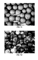
FIG. 7a illustrates microcapsules prepared according to sample 35 and heat treated at 200° C., wherein the scale is 2 mm;
FIG. 7b illustrates microcapsules prepared according to sample 35 and heat treated at 250° C., wherein the scale is 2 mm;
FIG. 7c illustrates microcapsules prepared according to sample 36 and heat treated at 200° C., wherein the scale is 2 mm;
FIG. 7d illustrates microcapsules prepared according to sample 36 and heat treated at 250° C., wherein the scale is 2 mm;
FIG. 7e illustrates microcapsules prepared according to sample 37 and heat treated at 200° C., wherein the scale is 2 mm; and
FIG. 7f illustrates microcapsules prepared according to sample 37 and heat treated at 250° C., wherein the scale is 2 mm;
FIG. 8a is an optical micrograph of microcapsules prepared according to example 2 and heat treated at 375° C., wherein the scale is 2 mm;
FIG. 8b is an optical micrograph of microcapsules prepared according to example 2 and heat treated at 495° C., wherein the scale is 2 mm;
FIG. 8c is an optical micrograph of a cross-section of the microcapsules prepared according to example 2 and heat treated at 375° C., wherein the scale is 2 mm;
FIG. 8d is an electron micrograph of a cross-section of the microcapsules prepared according to example 2 and heat treated at 495° C., wherein the scale is 200 μm;
FIG. 9 is a graph of time versus heat flow and time versus weight change for microcapsules prepared according to example 2 and measured using DSC and TGA;
FIG. 10 is an optical micrograph of glass beads, wherein the scale is 2 mm;
FIG. 11 is an optical micrograph of glass beads prepared with a single layer microcapsule shell, wherein the scale is 2 mm;
FIG. 12 is an optical micrograph of glass beads prepared with a sacrificial layer and a coating layer in the microcapsule shell, wherein the scale is 2 mm;
FIG. 13 is an optical micrograph of beads including a single layer microcapsule shell of FIG. 11 heat treated at over 600° C., wherein the scale is 2 mm;
FIG. 14 is an optical micrograph of a bead double layer microcapsule shell after heating at a temperature of 310° C., wherein the scale is 200 μm; and
FIG. 15 is an optical micrograph of residual carbon, wherein the scale is 200 μm.
DETAILED DESCRIPTION
The present disclosure relates to a process for the encapsulation of relatively high temperature phase change materials and, in particular, the encapsulation of relatively high temperature molten salts (inorganic salts or mixtures of inorganic salts) having melting points in the range of 200° C. to 600° C. The microcapsule shells remain intact or thermally stable (i.e., they do not crack or break apart) at elevated temperatures of up to 600° C. The present disclosure also relates to microcapsules produced by the methods discussed herein as well as the use of the microcapsules in various systems, including thermal energy storage systems.
As an initial matter, reference to high temperature phase change materials is understood herein as a reference to materials, such as molten salts, having a melting point in the range of 200° C. to 600° C. Furthermore, the phase change materials exhibit a latent heat of fusion that is equal to or greater than 1 kJ/mol, such as in the range of 0.5 kJ/mol to 3 kJ/mol, including all values and ranges therein. Molten salts for use herein include, for example, nitrates, nitrites, hydroxides, carbonates, chlorides of sodium, potassium, calcium, lithium and combinations thereof.
The relatively high temperature phase change materials are in the form of particles that preferably exhibit a largest cross-sectional dimension in the range of 0.5 millimeter to 100 millimeters, including all values and ranges therein, such as 0.5 millimeters to 50 millimeters, 1 millimeter to 10 millimeters, 25 millimeters to 50 millimeters, etc. In embodiments the particles may be prills. Prills are understood as granules of material that are formed into droplets as a melted liquid and solidify at room temperature. The size of the droplets and the resulting prills may be adjusted by using various processing methods. For example, prill size may be adjusted using screens of various sizes to form the drops or atomization to form relatively small prills.
FIG. 1 illustrates a microencapsulated phase change composition, wherein one or more layers of a coating 12 are applied over the core particles 14 to form a microcapsule shell over the particle core. The coating layer includes a binder, film former and inorganic filler as discussed further herein. The coating may have a thickness in the range of 50 to 1000 microns, including all values and ranges therein, such as 50 microns to 500 microns. FIG. 1 may be understood as a first embodiment where the particles include the coating layer 12 as illustrated and as described more fully herein.
A binder herein may preferably amount to an inorganic solvent based binder which at elevated temperature will cure and provide adhesive strength. The solvents may be water (e.g. a particle based suspension) or an organic solvent based system. One preferred example of such an inorganic water based binder includes CERAMABIND™ 644 available from Aremco of Valley Cottage, N.H. CERMABIND™ 644 is a colloidal alumina binder. Accordingly, the binder may include an inorganic colloid including dispersed phase inorganic particles in a continuous phase (water) wherein the inorganic particles (e.g. Al) may be present at a size range of 1 nm to 1000 nm.
The film formers are utilized herein serve to augment the binder, thereby improving the initial continuity of the formed coating over the particle. The film formers may preferably be naturally derived organic polymers and may include plant proteins (e.g. zein or prolamine protein), hydroxyl-propyl methyl cellulose (HPMC), ethyl cellulose and carboxy ethyl cellulose. The film formers may also include organic polymers, such a poly(vinyl chloride). Reference herein to film formers therefore include resins of relatively high MW (e.g., greater or equal to 5000) that are capable of initially forming a film in the coating formulations identified herein. The film formers may be provided in a carrier including, for example, alcohol such as ethyl alcohol, water, or combinations thereof, in addition to a surfactant, such as sodium lauryl sulfate. As discussed more fully below, the film formers are preferably removed with heat treatment.
Inorganic fillers include, for example, clays (particles of mineral silicates), including functionalized clays (CLOSITE™ 30B), montmorillonite clay (CLOSITE™ NA+), silica and micronized stainless steel. The aforementioned montmorillonite clay may be provided in natural form or be specifically functionalized with quaternary ammonium salts. The inorganic fillers herein may be present at a particle size of less than or equal to 50 μm, such as in the range of 1 μm to 50 μm, including all values and ranges therein, such as 2 μm to 25 μm, 2 μm to 13 μm, etc.
In preferable embodiments, the binder is to be present at a range of 5% to 30% by weight relative to the combination of the binder, film former and inorganic filler, including all values and ranges therein, and preferably 15% to 25% by weight. The film former may preferably be present in the range of 1% to 10% by weight relative to the combination of the binder, film former and inorganic filler, including all values and ranges therein, such as from 2.0% to 5.0 and preferably 3.1%. The inorganic filler may preferably be present in the range of 50% to 90% by weight relative to the combination of the binder, film former and inorganic filler, including all values and ranges therein, preferably from 70% to 90%, more preferably from 70% to 85% by weight, and more preferably 78.0% to 79.0%.
In more preferable embodiments, the coating specifically includes as the binder a colloidal alumina binder, ethyl cellulose as the film former, and montmorillonite clay as the inorganic filler. In particularly preferable embodiments, the coating layer includes ethyl cellulose film former present in the range of 1% by weight to 10% by weight relative to the binder, film former and inorganic filler including all values and ranges therein and preferably 2% to 5% by weight; a colloidal alumina binder present in the range of 15% to 25% by weight relative to the binder, film former and inorganic filler, including all values and ranges therein and preferably 17% to 23% by weight; and unmodified montmorillonite clay inorganic filler present in the range of 70% to 85% by weight relative to the binder, film former and inorganic filler, including all values and ranges therein and preferably 75% by weight to 80% by weight.
Referring again to FIG. 1, while one coating layer is illustrated, it is to be understood that such coating layer may itself be include 10 applied layers of the coating material over the phase change material particle 14. The coating layer may be present in the range of 20% by weight to 60% by weight of the microencapsulated phase change composition (i.e. phase change particle and shell) including all values and increments therein, such as 25% to 55%, or 40%, etc. The coating layer may have a thickness in the range of 50 μm to 500 μm.
The coating layer (binder, film former and inorganic filler) which forms the shell may be applied via the use of solvents. Accordingly, a surfactant may be employed, such as sorbitan alkyl esters. Preferred sorbitan alkyl esters include sorbitan monooleate, available as SPAN 80. The surfactant, when present, is present in the range of 0.5% by weight to 1% by weight, including all values and range therein, relative to the combination of the binder, film former, inorganic filler and the surfactant. Solvents that may be employed include water, alcohol, acetone and tetrahydrofuran.
In a further embodiment expanding upon FIG. 1 and as illustrated in FIG. 2, a sacrificial layer 26 in the microcapsule shell is optionally provided over the phase change particles 24 between the particle 24 and the coating layer 22. In forming the layers, the sacrificial layer 26 is first applied to the phase change particle 24 and then the coating 22 is applied over the phase change particle 24. The sacrificial layer, which is later removed by heating, ultimately provides a space that allows for or accommodates the thermal expansion of the phase change material.
The sacrificial layer 26 preferably includes an organic (carbon based) resin, such as a polymeric resin, that may be sacrificed (thermally degrade) upon exposure to heat. Accordingly, the sacrificial layer may include any resin that will degrade upon exposure to heat at a selected temperature. One may, e.g., utilize hydroxyl-propyl methyl cellulose, plant proteins (e.g. zein or prolamine protein), or ethyl cellulose. The sacrificial layer may be present in the range of 1% to 40% by weight of the microencapsulated phase change composition (i.e. phase change particle and shell) including all values and increments therein, such as 1% to 5% by weight, 3% to 35% by weight, 3% by weight etc. The sacrificial layer may have a thickness of 1.0 μm to 500 μm.
In preferable embodiments, where the microcapsule shells include, consist of, or consist essentially of a coating layer and a sacrificial layer, the coating layer again may preferably include a colloidal alumina binder, ethyl cellulose as a film former, a nanoclay as an inorganic filler, and hydroxypropyl methyl cellulose as a sacrificial layer (capable of thermal degradation). The ethyl cellulose film former is present in the coating layer at a range of 1% by weight to 10% by weight, the colloidal alumina binder present in the coating layer at a range of 15% by weight to 25% by weight and montmorillonite clay inorganic filler present in the coating layer at a range of 70% by weight to 85% by weight and the hydroxypropyl methyl cellulose as the sacrificial layer may be in the range of 1% to 20% by weight.
The sacrificial layer may be applied to the particles, for example, as a mixture or solution. The liquid phase includes, for example, water, alcohol such as ethyl alcohol, acetone, tetrahydrofuran or combinations thereof, such as ethyl alcohol and water. For example, in preferable embodiments, ethyl cellulose is utilized as a film former in the coating and hydroxypropyl methyl cellulose capable of thermal degradation is used as the sacrificial layer.
FIG. 3 illustrates another embodiment where an inner coating 38 and outer coating 32 are disposed about particle 34. The coating layers may again be based upon the use of binder, film former and inorganic filler as noted herein. As illustrated, the inner coating layer 38 is disposed between the particle 34 and the sacrificial layer 36 and may have a thickness of 1.0 μm to 100 μm. The inner coating layer 38 so positioned may therefore serve to slow or prevent reaction of the particle 34 with the decomposing sacrificial layer 36. The outer coating layer may have a thickness of 1.0 μm to 500 μm.
Furthermore, as described above, the sacrificial layer 36 is now present between the inorganic layer 38 and coating layer 32 in the microcapsule shell and may have a thickness of 100 μm to 500 μm. The sacrificial layer is again sourced from a polymer resin that is designed to decompose upon the application of heat. The sacrificial layer may again include, consist of, or consist essentially of those polymer resins that may be used for the film former. An example again includes hydroxypropyl methyl cellulose (HPMC). However, the composition used for the sacrificial layer is preferably a different composition than the film former used in the coating and as noted, is also thermally degradable and capable of forming a space for expansion of the phase change material. For example, the film former used in the coating layer may be ethyl cellulose and the sacrificial layer may be formed of hydroxypropyl methyl cellulose.
In such embodiments, where the microcapsule shells include, consist of or consist essentially of an inner coating layer 38, a sacrificial layer 36 and an outer coating layer 32, the outer coating layer 32 is preferably present in the range of 20% by weight to 40% by weight including all values and increments therein of the encapsulated phase change composition, and preferably 25% by weight to 35% by weight, and more preferably 27% by weight to 31% by weight and more preferably, 29% by weight. The inner coating layer 38 is present in the range of 1% to 20% by weight of the encapsulated phase change composition, including all values and ranges therein, and preferably 5% to 15% by weight, and more preferably 7% to 11% by weight, and more preferably 9%. The sacrificial layer may be present in the range of 10% by weight to 30% by weight of the encapsulated phase change composition, including all values and increments therein, such as 15% to 25% by weight, 17% to 21% by weight, 19% by weight etc.
The microcapsule shell (inner coating layer, sacrificial layer and outer coating layer) may be present in the range of 22 wt % to 65 wt % of the microencapsulated phase change composition, including all values and ranges therein, such as 25% to 50%, 27% to 54%, 40%, 44%, 54%, etc. Thus, the phase change composition may be present in the range of 35% to 78% by weight, including all values and ranges therein. Furthermore, the average weight of the phase change particles may be in the range of 20 milligrams to 250 milligrams, including all values and ranges therein, such as 20 to 60 milligrams, 25 milligrams, 50 milligrams, etc.
The resulting coating (inner coating layer, sacrificial layer and outer coating layer) preferably has an overall thickness in the range of 50 μm to 1000 μm, including all values and ranges therein and preferably from 50 μm to 500 μm. The average size of the microencapsulated particles is in the range of 100 μm to 50 mm, including all values and ranges therein.
The microcapsule shells as described herein remain intact and thermally stable at temperatures of 200° C. or greater. For example, the microcapsules may remain thermally stable from 200° C. and up to 350° C., including all values and increments therein. In being thermally stable, it is understood that less than 5.0% of the microcapsule shells of a given sample rupture, including all values and ranges from 0% to 5.0%.
Furthermore, in embodiments where the microcapsule shell includes an inner coating layer, a sacrificial layer and an outer coating layer, the shells remain intact and thermally stable at temperatures of 200° C. and up to 600° C., wherein less than 5% of the microcapsule shells rupture, including all values and ranges from 0% to 5%.
Also disclosed herein is a method of encapsulating a phase change material and includes suspending or fluidizing particles of a phase change material in a medium and applying the microcapsule shell over the particles. Suspension or fluidizing as understood herein is the separation of the particles through a medium, such as by lifting of the particles apart from one another. In embodiments, the suspension medium includes air. However, other fluids may be used as a suspension medium as an alternative to or in addition to the air. For example, gases including inert gases or liquids such as water or organic solvents may be used. In suspension, the shell layers are sprayed on the particles.
Preferably, the phase change materials are suspended in a fluidized bed or an air suspension bed. FIG. 4 illustrates an air suspension bed including a Wurster insert useful for providing the coatings discussed herein. The air suspension bed 400 generally includes a containment vessel or a bowl 402 and a distribution plate at the base of the vessel 104 including a plurality of holes defined therein through which a suspension medium is supplied. Thus, the fluidized bed is generally defined by the walls of the vessel and the distribution plate at the bottom of the vessel. The suspension medium is fed into the vessel 402 through the plate and forced up through the particles 406 in the vessel. A partition 408, such as a funnel, is placed in the bottom of the bed and, optionally, in the center of the bed, forming a high-velocity region 410 a of the fluidized bed. A spray nozzle 412 is provided in the high-velocity region 410 a for applying the coating and other, optional layers over the particles.
In the high-velocity region 410 a, the suspension medium M is forced through the distribution plate at a relatively high velocity, which forces the particles 406 at a relatively high velocity through the high-velocity region 410 a where the particles 406 are separated and coating is applied. While still suspended by the suspension medium in the vessel, the coating dries. The particles then slow down, i.e., the force of gravity overcomes the drag force suspending the particles, and fall into the low-velocity region 410 b of the vessel 402. In the low-velocity region 410 b of the vessel, the suspension medium M is forced through the distribution plate at a sufficient velocity, which is relatively less than the velocity to feed the particles into the high-velocity region 410 a, to allow the particles to circulate towards the bottom of the vessel, where the particles are drawn back into the partition 408.
After application of the coating layer 12 to the particles of phase change composition 14 (see again FIG. 1), the particles are heat treated. Such heat treatment may preferably be applied at temperatures of 400° C. or less. The heat treatment serves to remove all or a portion of the film former noted herein. For example, 80% or more of the film former may be removed and preferably 90% or more of the film former is removed. In addition, as illustrated in FIG. 2, if the sacrificial layer 26 is present, it too may be removed with such heat treatment. Accordingly, it may be appreciated that after heating, the coating may be described as a matrix of inorganic filler (e.g. clay) dispersed in a matrix of binder and film former residue.
The above identified particles contribute to the formation herein of a system for thermal energy storage. The microencapsulated phase change particles may be provided or packed in a storage stank. Thermal energy may be accumulated from, e.g., an active solar collector, steam or other heat source. A heat transfer fluid, such as oil, molten salts, or water, may transfer the heat from the heat source to the microencapsulated phase change particles, which contact the heat transfer fluid. In embodiments, the heat transfer fluid includes HITEC, a low melting molten salt mixture of inorganic nitrate salts. Upon melting, the particles absorb heat and upon cooling, the particles release their absorbed heat to a surrounding medium. It is therefore noted herein that a particular problem with solar collectors is that the temperatures that may be achieved can be relatively high, and in the range of 400° C. to 600° C. Accordingly, a need exists for phase change particles (alkali salts) that can be utilized in such temperature ranges. The coatings noted herein now provide a solution for this problem by way of their elevated temperature resistance.
Furthermore, relatively high surface areas may be preferred to promote relatively rapid heat transfer between the microencapsulated phase change materials and surrounding environment. Relatively high surface area containment may be achieved using microencapsulation where the beads of alkali salts herein are encapsulated within the identified protective shells. Final capsule size can be adjusted to change the surface area and heat transfer rate, and the protective shell also prevents mixing with surrounding fluids.
EXAMPLES Example 1
Potassium nitrate prills were coated with various coating compositions described in Table 1 presented below. For the binder, Ceramabind 380 (referred to in the table as “380”) and Ceramabind 644A (referred to in the table as “644A”) were used. Film formers included, zein, hydroxypropyl methyl cellulose (HMPC), ethyl cellulose (EC), carboxy methyl cellulose (CMC) and poly(vinyl chloride) (PVC). Inorganic fillers included carbon black (carbon), montmorillonite clay functionalized with quaternary ammonium salts (Mod Clay), natural montmorillonite clay (Clay), and micronized stainless steel (Steel). Sorbitan monooleate was utilized as a surfactant (SPAN 80). Water and ethanol were used as solvents.
TABLE 1
Coating Compositions
No. of Binder Film % Inorganic
Sample Coatings (B) % B Former (FF) FF (I) % I Surfactant
1 1
2 1
3 1
4 1 380 100
5 1 380 25 Carbon 75
6 1 380 25 Carbon 75
7 1 380 25 Mod Clay 75
8 1 644A 100
9 1 644A 75 HPMC 25
10 1 644A 30 HPMC 10 Carbon 60 SPAN80
11 1 644A 30 HPMC 10 Mod Clay 60 SPAN80
12 1 644A 30 HPMC 10 Steel 60 SPAN80
14 1 644A 30 HPMC 10 Silica 60 SPAN80
15 2 644A 30 HPMC 10 Mod Clay SPAN80
16 2 644A 30 HPMC 10 Steel 60 SPAN80
17 2 644A 30 HPMC 10 Mod Clay 60 SPAN80
18 4 644A 30 HPMC 10 Mod Clay 60 SPAN80
19 4 644A 86 HPMC 14 SPAN80
20 2 644A 32 HPMC 2.5 Steel 65 SPAN80
21 2 644A 30 HPMC 10 Clay 60 SPAN80
22 HPMC 100
23 2 644A 32 HPMC 2.5 Clay 65 SPAN80
26 EC 100
27 Zein 100
28 2 644A 75 EC 25 SPAN80
29 2 644A 30 EC 10 Clay 60 SPAN80
30 2 644A 27 EC 19 Clay 54 SPAN80
31 2 644A 32 EC 2.5 Clay 65 SPAN80
32 2 644A 32 EC 5 Clay 63 SPAN80
33 4 644A 32 EC 5 Clay 63 SPAN80
34 4 644A 32 EC 2.5 Clay 65 SPAN80
35 2 644A 32 EC 5 Clay 63 SPAN80
36 2 644A 32 EC 5 Clay 63 SPAN80
37 2 644A 32 EC 5 Clay 63 SPAN80
38 CMC 100
39 CMC 100
41 2 644A 32 EC 5 Steel 63 SPAN80
42 2 644A 32 EC 5 Clay 63 SPAN80
43 2 644A 30 EC 10 Steel 60 SPAN80
44 HPMC 100
45 2 644A 32 EC 5 Clay/ 32/ SPAN80
Steel 32
46 2 644A 32 EC 5 Clay/ 47/ SPAN80
Steel 16
47 644A PVC 100
Upon initial review, the following observations were made. Samples 1 and 2 include prills coated with zein for both the film former and binder with carbon black (sample 1) and montmorillonite clay (sample 2) according to the formulations set forth in Table 1. The resulting coating thickness was approximately 150 μm. FIG. 5a illustrates optical micrographs of the prills before coating, FIG. 5b illustrates optical micrographs of the prills after coating, and FIG. 5c illustrates optical micrographs of a cross section of the prills. Upon exposure to heat at 200° C., the thermal stability of these capsules was found to be poor.
In addition, a number of different combinations of film formers and binders were then tested with and without the addition of a inorganic filler. Without the use of a film former, (samples 4 through 7) the coatings including a binder and the inorganic filler, were rough and potentially porous.
Thermal stability studies were then performed, the results of which are presented in Table 2. The thermal treatments were performed at 200° C., 300° C., and 375° C. Ramp rate to achieve the treatment temperatures were 0.1° C./min and for the fast run the capsules were placed into an oven preheated at 300° C. and the rate of temperature increase was understood to be 50° C./min. Ramp rates were adjusted to lower values when gas is evolved from within the capsule. The final weight was determined before heating and after the addition of coatings.
300° C. 300° C. Start Final
Sample
200° C. Slow Fast 375° C. Wt. Wt. Final % Comments
1 X X 50
2 X X 50
3 X 50
4 X X 50
5 X 50
6 X X 50
7 X X 50
8 X X 50
9 X X X 50
10 X X 50
11 X X X 50 65 23.08
12 X X X 50
14 X X 50
15 X X X 50
16 X X 50 66.7 25.04
17 X X X 50
18 X X 50
19 X X 50
20 X X 50 61.8 19.09
21 X X 50 71.9 30.46
22 X 50 51.8 3.475
23 X X 50
26 X 50
27 X 50
28 X 50
29 X Y Y X 50
30 X X 50 82.5 39.39
31 Y Y X X 50 68.7 27.22
32 Y Y X X 50 70.8 28.38
33 Y Y Y X 50 108.3 53.83
34 X X X 50 112 55.36
35 Y Y Y X 50 77.3 35.32 Applied on
sample 22
capsules
36 X X X X 51 84 39.29 Applied on
sample 27
capsules
37 X X X X 49 72.8 32.69 Applied on
sample 26
capsules
38 X 50
39 X 50
41 X X X X 50
42 X X 42.6 73.3 41.88
43 X X 50
44 160 164.6 2.795
45 X X 50 58.7 14.82 Applied on
sample 44
capsules
46 X 50 77.2 35.23 Applied on
sample 44
capsules
47 50
Thermal treatment indicated that the coating compositions including 32% wt Ceramabind 644A as a binder, 5% wt ethyl cellulose as a film former, and 63% natural clay as an inorganic filler (samples 33 and 35), remained stable at temperatures of up to and including 300° C. FIG. 6a illustrates optical micrographs of potassium nitrate beads with microcapsule shells including 32% Ceramabind, 5% wt ethyl cellulose, and 63% natural clay shells. FIG. 6b illustrates optical micrographs of those shells heat treated at 200° C. for 12 to 24 hours. FIG. 6c illustrates the same microcapsules heat treated at 275° C. As illustrated the shells remained intact and were thermally stable at the elevated temperature. FIG. 6d illustrates optical micrographs of similarly prepared shells with 32% Ceramabind, 2.5% wt ethyl cellulose, and 65% natural clay shells treated at 275° C. for 12 to 24 hours.
Optical micrographs of samples 35, 36 and 37, including sacrificial layers, are illustrated in FIGS. 7a, 7b, 7c, 7d, 7e and 7f after heat treatments at 200° C. and 250° C. for 12 to 24 hours. As seen in the images, coating sample 35 including hydroxypropyl methyl cellulose as a sacrificial layer and ethyl cellulose as the film former at 5% by wt remained intact at both heat treatment temperatures of 200° C. (FIG. 7a ) and at least 50% of the microcapsule shells remained intact and were thermally stable at 250° C. (FIG. 7b ). Where as the sample including zein as a sacrificial layer, sample 36 began to crack at 200° C. (FIG. 7c ) and completely deteriorate at 250° C. (FIG. 7d ). The microcapsules of sample 37, including ethyl cellulose as a sacrificial layer, remained intact and were thermally stable when heat treated at temperatures of 200° C. and 250° C. (FIGS. 7e and 7f ).
Example 2
Preparation of microencapsulated phase change compositions including a coating layer, a sacrificial layer and an inorganic layer, such as those illustrated in FIG. 2, began with the use of salt core prills of potassium nitrate (KNO3) with a starting size in the range of 2 to 4 mm. The coating layer and inorganic layer were prepared from the same composition according to the formulation set forth in Table 3.
TABLE 3
Coating and Inorganic Layer Formulation
Component Amount (g)
Binder Alumina Binder - 6
Ceramabind 644A
Film Former Ethyl Cellulose - 1
Aquacoat
Inorganic Filler Montmorillonite Clay - 7.5
Cloisite Na+
Surfactant Sorbitan monooleate - 0.1
Span 80
Carrier Water 150
Ethanol 50
The sacrificial layer was prepared from a solution of hydroxypropyl methyl cellulose in 90/10 ethanol/water. The concentration of the solution of 4% of HPMC in water/ethanol. The HPMC was METHOCEL E6LV available from DOW, with 29% methoxyl content.
The layers were then applied to the prills utilizing the method described above, i.e. First the inorganic coated layer was applied, then the sacrificial layer was applied and then the coating layer was applied.
The salt core prills were present at 44% by weight of the final product, the inorganic layer was present at 9% by weight of the final product, the sacrificial layer was present at 19% by weight of the final product and the coating layer was present at 29% by weight of the final product.
The prepared microencapsulated phase change particles were then heat treated in to determine the stability of the capsules. The heat treatment conditions were as set forth in Table 4. Heat treatments were successive with 1° C./min ramps in between.
TABLE 4
Heat Treatment Conditions
Sample Temperature (° C.) Ramp Time (hours)
1 225 12
2 250 12
3 260 12
4 270 12
5 280 12
6 290 8
7 300 12
8 310 8
9 315 12
10 320 8
11 325 12
12 25° C. to 50° increments 4-8 hour ramp
The heat treated capsules are illustrated in FIGS. 8a, 8b, 8c and 8d . FIGS. 8a and 8b show images of the treated capsules, which were treated at 375° C. and 495° C., respectively. Color change is caused by oxidation and removal of the carbon based sacrificial material. The corresponding cross-sections illustrated in FIGS. 8c and 8d , for FIGS. 8a and 8b respectively, illustrate that upon cooling the salts contract and solidify inside the capsules, typically on the inner surface of the capsule shell leaving a void in the center of the capsule.
The microcapsules were also thermally cycled ten times between 250° C. and 400° C. to melt and freeze the salt within the capsules. FIG. 9 illustrates the differential scanning calorimetry (DSC) curve and the thermogravimetric analysis (TGA) curve. As illustrated, the weight loss stabilizes over the 10 hour run. The DSC results also illustrate the melting and freezing during each thermal cycle, demonstrating that the microcapsules may be exposed to cyclic temperatures during thermal energy storage.
To demonstrate the robustness of the microcapsules to relatively high temperature environments without the interference of potassium nitrate (KNO3) reactivity and volume expansion, capsules were prepared with a glass core, which are illustrated in FIG. 10. Two glass bead samples were prepared; one with a clay shell illustrated in FIG. 11 and one with a double layer illustrated in FIG. 12, i.e., sacrificial layer and coating layer shell of HPMC and clay, binder and film former. The single layer samples were prepared using the composition described above for the inorganic and coating layers and the double layer samples were prepared using the compositions described above for the sacrificial layer and the coating layer.
FIG. 13 illustrates the single layer capsule heated at over 600° C. for 12 hrs. Such heating demonstrates the suitability of the coating compositions for relatively high temperature applications as the microcapsule shells remained intact and were thermally stable. FIG. 14 illustrates a double layer capsule after heating at a temperature of 310° C. with residual carbon and FIG. 15 illustrates a piece of carbon sacrificial layer that did not completely burn away during the heat treatment process. The double layer capsule did rupture in most cases, indicated that the rupture problem is likely due to the evolution in gas, rather than due to the expansion of the KNO3 core.
The foregoing description of several methods and embodiments has been presented for purposes of illustration. It is not intended to be exhaustive or to limit the claims to the precise steps and/or forms disclosed, and obviously many modifications and variations are possible in light of the above teaching. It is intended that the scope of the invention be defined by the claims appended hereto.

Claims (12)

What is claimed is:
1. A method of encapsulating microcapsules containing phase change material, comprising:
supplying a phase change material comprising an inorganic salt selected from nitrates, nitrites, and hydroxides of potassium, lithium and combinations thereof, having a melting point of 200° C. to 600° C., and a largest cross-sectional dimension of 0.5 mm to 100 mm;
applying a coating to said phase change material wherein said coating includes an inorganic binder, a film former comprising an organic polymer at a MW of greater than or equal to 5000, and an inorganic filler at a particle size of less than or equal to 50 μm and wherein said coating has a thickness of 50 μm to 1000 μm; and
heating said coating at a temperature in the range 200° C. to 400° C. wherein at least a portion of said organic polymer of said film former is removed to form said microcapsules, wherein from 0% to 5% of said microcapsules rupture at temperatures of 200° C. to 600° C.
2. The method of claim 1 wherein said binder is present in the range of 5% to 30% by wt. relative to the combination of binder, film former and inorganic filler, said film former is present in the range of 1% to 10% by wt. relative to the combination of binder, film former and inorganic filler, and said inorganic filler is present in the range of 50% to 90% by wt. relative to the combination of binder, film former and inorganic filler.
3. The method of claim 1, wherein said binder comprises an inorganic aluminum colloid and is present in the range of 15% to 25% by wt. relative to the combination of binder, film former and inorganic filler, said film former comprises ethyl cellulose and is present in the range of 1% to 10% by wt. relative to the combination of binder, film former and inorganic filler, and said inorganic filler comprises mineral silicate and is present in the range of 70% to 85% by wt. relative to the combination of binder, film former and inorganic filler.
4. The method of claim 1 wherein 80% or more of the organic polymer of the film former is removed with heating.
5. The method of claim 1 wherein said inorganic binder comprises an inorganic solvent based binder applied to said phase change material comprising dispersed phase inorganic particles wherein said particles are present at a size of 1 nm to 1000 nm.
6. The method of claim 1 wherein said inorganic binder comprises dispersed aluminum particles.
7. The method of claim 1 wherein said inorganic filler comprises mineral silicates, clay, silica, and/or micronized stainless steel.
8. The method of claim 1, wherein said microcapsule shell further includes a sacrificial layer, wherein said sacrificial layer is disposed between said phase change material and said coating layer and wherein said heating of said coating removes said sacrificial layer and provides a space as between said coating layer and said phase change material.
9. The method of claim 8 wherein said sacrificial layer comprises an organic polymeric resin that thermally degrades upon exposure to heat.
10. The method of claim 8 wherein said sacrificial layer comprises hydroxyl-propyl methyl cellulose, plant protein or ethyl cellulose.
11. The method of claim 8 wherein said sacrificial layer has a thickness of 1.0 μm to 500 μm.
12. The method of claim 1 wherein said microcapsules are packed in a storage tank containing a heat transfer fluid.
US13/749,446 2013-01-24 2013-01-24 Encapsulation of high temperature molten salts Active 2033-06-07 US9650556B2 (en)

Priority Applications (1)

Application Number Priority Date Filing Date Title
US13/749,446 US9650556B2 (en) 2013-01-24 2013-01-24 Encapsulation of high temperature molten salts

Applications Claiming Priority (1)

Application Number Priority Date Filing Date Title
US13/749,446 US9650556B2 (en) 2013-01-24 2013-01-24 Encapsulation of high temperature molten salts

Publications (2)

Publication Number Publication Date
US20140202541A1 US20140202541A1 (en) 2014-07-24
US9650556B2 true US9650556B2 (en) 2017-05-16

Family

ID=51206768

Family Applications (1)

Application Number Title Priority Date Filing Date
US13/749,446 Active 2033-06-07 US9650556B2 (en) 2013-01-24 2013-01-24 Encapsulation of high temperature molten salts

Country Status (1)

Country Link
US (1) US9650556B2 (en)

Cited By (1)

* Cited by examiner, † Cited by third party
Publication number Priority date Publication date Assignee Title
EP3450010A1 (en) * 2017-08-30 2019-03-06 National Research-Development Institute for Non-ferrous and Rare Metals (IMNR) Inorganic phase change materials based on potassium nitrate micro encapsulation process in a nanostructured inorganic zinc oxide shell with application in thermal energy storage

Families Citing this family (7)

* Cited by examiner, † Cited by third party
Publication number Priority date Publication date Assignee Title
WO2015095271A1 (en) * 2013-12-17 2015-06-25 All Cell Technologies, Llc Flexible phase change material composite for thermal management systems
CN105855537B (en) * 2016-03-24 2018-01-19 中国科学院上海应用物理研究所 A kind of inorganic non-metallic involucrum high-temperature phase-change heat storage microcapsules and preparation method thereof
CN105810812B (en) * 2016-05-04 2018-03-06 中国科学院上海应用物理研究所 A kind of assemble method of spherical high-temperature phase transition heat storage element and the heat accumulation element being consequently formed
CN107461946A (en) * 2016-06-06 2017-12-12 中海阳能源集团股份有限公司 A kind of solar energy heat-collecting heat-storage medium and preparation method thereof
CN107473201A (en) * 2017-08-22 2017-12-15 邹远升 A kind of anti-corrosion fused salt material and its preparation method and application
CN110332738A (en) * 2019-07-10 2019-10-15 广东五星太阳能股份有限公司 A kind of composite phase-change material regenerator
CN114854376A (en) * 2022-05-25 2022-08-05 安徽理工大学 Phase change microcapsule encapsulated by composite coating and preparation method thereof

Citations (17)

* Cited by examiner, † Cited by third party
Publication number Priority date Publication date Assignee Title
US4219072A (en) 1978-02-10 1980-08-26 Barlow Donald W Sr Phase change material heat exchanger
US4505953A (en) 1983-02-16 1985-03-19 Pennwalt Corporation Method for preparing encapsulated phase change materials
US4513053A (en) 1983-06-13 1985-04-23 Pennwalt Corporation Encapsulated phase change thermal energy storage materials and process
US4512388A (en) 1981-06-19 1985-04-23 Institute Of Gas Technology High-temperature direct-contact thermal energy storage using phase-change media
US4777154A (en) 1978-08-28 1988-10-11 Torobin Leonard B Hollow microspheres made from dispersed particle compositions and their production
US4873038A (en) 1987-07-06 1989-10-10 Lanxide Technology Comapny, Lp Method for producing ceramic/metal heat storage media, and to the product thereof
US5007478A (en) 1989-05-26 1991-04-16 University Of Miami Microencapsulated phase change material slurry heat sinks
US5207268A (en) 1991-06-28 1993-05-04 Deutsche Forschungsanstalt Fuer Luft- Und Raumfahrt E.V. High-temperature heat storage system
US20020103074A1 (en) * 1999-01-27 2002-08-01 Wheelock Thomas D. Core-in-shell sorbent for hot coal gas desulfurization
US6652771B2 (en) 2001-07-11 2003-11-25 Ronald M. Carn Phase change material blend, method for making, and devices using same
US20050247906A1 (en) 2002-07-12 2005-11-10 Mark Neuschutz Heat-storage means
US20070148447A1 (en) * 2005-12-28 2007-06-28 Kimberly-Clark Worldwide, Inc. Wipes including microencapsulated delivery vehicles and phase change materials
US20080135245A1 (en) * 2005-02-04 2008-06-12 Oxane Materials, Inc. Composition and Method For Making a Proppant
US20100087115A1 (en) * 2008-10-08 2010-04-08 Microtek Laboratories, Inc. Microencapsulation of a phase change material with enhanced flame resistance
US20100230075A1 (en) 2009-03-11 2010-09-16 Terrafore, Inc. Thermal Storage System
US20120018116A1 (en) 2010-07-21 2012-01-26 Terrafore, Inc Thermal energy storage system comprising encapsulated phase change material
US9493695B2 (en) * 2011-07-18 2016-11-15 University Of South Florida Method of encapsulating a phase change material with a metal oxide

Patent Citations (17)

* Cited by examiner, † Cited by third party
Publication number Priority date Publication date Assignee Title
US4219072A (en) 1978-02-10 1980-08-26 Barlow Donald W Sr Phase change material heat exchanger
US4777154A (en) 1978-08-28 1988-10-11 Torobin Leonard B Hollow microspheres made from dispersed particle compositions and their production
US4512388A (en) 1981-06-19 1985-04-23 Institute Of Gas Technology High-temperature direct-contact thermal energy storage using phase-change media
US4505953A (en) 1983-02-16 1985-03-19 Pennwalt Corporation Method for preparing encapsulated phase change materials
US4513053A (en) 1983-06-13 1985-04-23 Pennwalt Corporation Encapsulated phase change thermal energy storage materials and process
US4873038A (en) 1987-07-06 1989-10-10 Lanxide Technology Comapny, Lp Method for producing ceramic/metal heat storage media, and to the product thereof
US5007478A (en) 1989-05-26 1991-04-16 University Of Miami Microencapsulated phase change material slurry heat sinks
US5207268A (en) 1991-06-28 1993-05-04 Deutsche Forschungsanstalt Fuer Luft- Und Raumfahrt E.V. High-temperature heat storage system
US20020103074A1 (en) * 1999-01-27 2002-08-01 Wheelock Thomas D. Core-in-shell sorbent for hot coal gas desulfurization
US6652771B2 (en) 2001-07-11 2003-11-25 Ronald M. Carn Phase change material blend, method for making, and devices using same
US20050247906A1 (en) 2002-07-12 2005-11-10 Mark Neuschutz Heat-storage means
US20080135245A1 (en) * 2005-02-04 2008-06-12 Oxane Materials, Inc. Composition and Method For Making a Proppant
US20070148447A1 (en) * 2005-12-28 2007-06-28 Kimberly-Clark Worldwide, Inc. Wipes including microencapsulated delivery vehicles and phase change materials
US20100087115A1 (en) * 2008-10-08 2010-04-08 Microtek Laboratories, Inc. Microencapsulation of a phase change material with enhanced flame resistance
US20100230075A1 (en) 2009-03-11 2010-09-16 Terrafore, Inc. Thermal Storage System
US20120018116A1 (en) 2010-07-21 2012-01-26 Terrafore, Inc Thermal energy storage system comprising encapsulated phase change material
US9493695B2 (en) * 2011-07-18 2016-11-15 University Of South Florida Method of encapsulating a phase change material with a metal oxide

Non-Patent Citations (10)

* Cited by examiner, † Cited by third party
Title
"Phase-Change Thermal Energy Storage" Final Subcontract Report on the Symposium held Oct. 19-20, 1988, Helendale, CA, Luz International Ltd., Solar Energy Research Institute, and CBY Associates, Inc.; Prepared under Subcontract No. HH-9-18108-1, for the US Dept. of Energy; Report No. SERI/STR-250-3516, US Category: 202 DE89009426; Nov. 1989 (151 pgs).
"Survey of Thermal Storage for Parabolic Trough Power Plants"; Pilkington Solar International GmbH; National Renewable Energy Laboratory (NREL) Subcontractor's Report NREL/SR-550-27925; for Period of Performance: Sep. 13, 1999-Jun. 12, 2000 (61 pgs).
Groenendaal, B.J.; Solar Thermal Power Technologies, Monograph in the Framework of the VLEEM Project, Jul. 2002, ECN-C-02-062 (50 pgs).
Kelly, B., et al; "Thermal Storage Commercial Plant Design Study for a 2-Tank Indirect Molten Salt System"; Final Report May 13, 2002-Dec. 31, 2004; National Renewable Energy Laboratory, Subcontract Rpt. NREL/SR-550-40166, Jul. 2006; prepared under Subcontact No. AAA-2-32432-01 (32 pgs).
Shin, Y., et al, "Development of Thermoregulating Textile Materials With Microencapsulated Phase Change Materials (PCM). IV. Performance Properties and Hand of Fabrics Treated with PCM Microcapsules"; Journal of Applied Polymer Science, Vo. 97, 2005, Thermoregulating Textile Material IV (pp. 910-915).
Su, J-F., et al; Preparation and Characterization of Polyurethane Microcapsules Containing n-Octadecane with Styrene-Maleic Anhydride as a Surfactant by Interfacial Polycondensation, Journal of Applied Polymer Science, vol. 102, 2006, (pp. 4996-5006).
Tamme, R., "Phase-Change Storage Systems"; Workshop on Thermal Storage for Trough Power Systems, Feb. 20-21, 2003, Golden CO. (21 pgs).
U.S. Office Action issued Apr. 23, 2015 in U.S. Appl. No. 13/187,398 (20 pgs).
U.S. Office Action issued Jan. 15, 2015 in U.S. Appl. No. 13/187,398 (18 pgs).
U.S. Office Action issued Mar. 22, 2016 in U.S. Appl. No. 13/187,398 (21 pgs).

Cited By (1)

* Cited by examiner, † Cited by third party
Publication number Priority date Publication date Assignee Title
EP3450010A1 (en) * 2017-08-30 2019-03-06 National Research-Development Institute for Non-ferrous and Rare Metals (IMNR) Inorganic phase change materials based on potassium nitrate micro encapsulation process in a nanostructured inorganic zinc oxide shell with application in thermal energy storage

Also Published As

Publication number Publication date
US20140202541A1 (en) 2014-07-24

Similar Documents

Publication Publication Date Title
US9650556B2 (en) Encapsulation of high temperature molten salts
WO2017173176A1 (en) Microencapsulated composite phase change materials
KR970008262B1 (en) Global shaped capsule of thermal energy storage material & process
Su et al. Development of microencapsulated phase change material for solar thermal energy storage
CN103370104B (en) Self-excitation hairdo fire-fighting agent
JP2008507605A (en) Microcapsule manufacturing method using latent heat storage material
Feczkó et al. Latent heat storage by silica-coated polymer beads containing organic phase change materials
CN103464066B (en) A kind of preparation method of phase-change material micro-capsule
WO2012177181A1 (en) Microencapsulated fire suppressant and method for producing same
RU2420350C2 (en) Microcapsules with water or water solution (versions) and method of their production (versions)
WO2017105352A1 (en) Synthesis of inorganic sio2 microcapsules containing phase change materials and applications therein
JPS604792A (en) Encapsulized phase change heat energy storage substance and method
US8822618B2 (en) Microcapsule and methods of making and using microcapsules
JP2631841B2 (en) Latent heat storage material microcapsules
CN109956860A (en) Preparation method of ibuprofen spherical crystal
CN103880569A (en) Surface modification and coating method for ammonium dinitramide
CN106590539A (en) Composite phase transition material using silica gel as matrix and preparation method thereof
JPH05117642A (en) Cold reserving material
Al-Shannaq et al. Methods for the synthesis of phase change material microcapsules with enhanced thermophysical properties—A state-of-the-art review
EP1950265A1 (en) Heat storage material microcapsule, heat storage material microcapsule dispersion and heat storage material microcapsule solidified product
JP2006063328A (en) Microencapsulated heat-accumulating solid material
US20230416544A1 (en) Polymer/phase change material composite ink for three-dimensional printing by direct ink writing
Singh et al. A novel strategy for temperature controlling of chocolates through 1-dodecanol embedded polyurea coated barium alginate beads
JP2007145943A (en) Heat storage material microcapsule, heat storage material microcapsule dispersion and heat storage material microcapsule solid matter
JP2006097000A (en) Heat storage material-microencapsulated solid material

Legal Events

Date Code Title Description
AS Assignment

Owner name: ENERGY, UNITED STATES DEPARTMENT OF, DISTRICT OF C

Free format text: CONFIRMATORY LICENSE;ASSIGNOR:SOUTHWEST RESEARCH INSTITUTE;REEL/FRAME:030082/0147

Effective date: 20130207

AS Assignment

Owner name: TERRAFORE, INC., CALIFORNIA

Free format text: ASSIGNMENT OF ASSIGNORS INTEREST;ASSIGNOR:MATHUR, ANOOP KUMAR;REEL/FRAME:030700/0155

Effective date: 20130614

AS Assignment

Owner name: SOUTHWEST RESEARCH INSTITUTE, TEXAS

Free format text: ASSIGNMENT OF ASSIGNORS INTEREST;ASSIGNOR:OXLEY, JAMES D.;REEL/FRAME:030921/0557

Effective date: 20130628

AS Assignment

Owner name: TERRAFORE, INC., MINNESOTA

Free format text: CORRECTIVE ASSIGNMENT TO CORRECT THE ADDRESS OF ASSIGNEE TO 100 SOUTH 5TH STREET, SUITE 1900, MINNEAPOLIS, MINNESOTA 55402 PREVIOUSLY RECORDED ON REEL 030700 FRAME 0155. ASSIGNOR(S) HEREBY CONFIRMS THE CHANGE OF ASSIGNEE'S ADDRESS IN THE ASSIGNMENT OF ASSIGNORS' INTEREST;ASSIGNOR:MATHUR, ANOOP KUMAR;REEL/FRAME:032091/0492

Effective date: 20130717

FEPP Fee payment procedure

Free format text: PAYOR NUMBER ASSIGNED (ORIGINAL EVENT CODE: ASPN); ENTITY STATUS OF PATENT OWNER: SMALL ENTITY

STCF Information on status: patent grant

Free format text: PATENTED CASE

FEPP Fee payment procedure

Free format text: MAINTENANCE FEE REMINDER MAILED (ORIGINAL EVENT CODE: REM.); ENTITY STATUS OF PATENT OWNER: SMALL ENTITY

FEPP Fee payment procedure

Free format text: SURCHARGE FOR LATE PAYMENT, SMALL ENTITY (ORIGINAL EVENT CODE: M2554); ENTITY STATUS OF PATENT OWNER: SMALL ENTITY

MAFP Maintenance fee payment

Free format text: PAYMENT OF MAINTENANCE FEE, 4TH YR, SMALL ENTITY (ORIGINAL EVENT CODE: M2551); ENTITY STATUS OF PATENT OWNER: SMALL ENTITY

Year of fee payment: 4